new technology to solve vibration and fabrication problems
TRANSCRIPT

New Technology to Solve Vibration and Fabrication Problems in U-Tube Bundles
Jonathan Breaux, Thermal Designer & Estimating Manager, Gulf Coast Exchanger
Russel Miller, Vice-President, Gulf Coast Exchanger
Amar Wanni, Ph.D. (Inventor)
Thomas Rudy, Ph.D.
1
Introducing Vibration Problems
Cause downtime due to unplanned
maintenance
Lead to loss of revenue
Path Forward:
Must be established quickly
Tube plugs are common fix
Tube plugging may lead to additional concerns
if caused by Flow-Induced Vibration2

Introducing Vibration Problems
Main Modes of Flow-Induced Vibration
Acoustic Vibration
‒ Intense noise, not known to cause tube damage
‒ Solution: install one or two axial deresonating baffles
Fluid-Elastic Instability
‒ Most common mode of failure
Vortex Shedding
‒ Tubes may shear quickly once a crack is initiated
3

Introducing Vibration Problems
Fluid-Elastic Instability
‒ Orbital motion of tubes causes
gradual removal of metal
‒ Failure could occur within hours,
years, or decades depending on
severity of vibration
‒ May not be revealed during
inspection
4
Baffle
Tube

Introducing Vibration Problems
Vortex Shedding
‒ Tube-on-Tube collisions at mid-span or stress
fractures near tubesheets or baffles
‒ Stress Fractures: Tubes may shear very quickly
once a crack is initiated
‒ Cracks may take years or decades to form based
on severity of vibration and resonance matching
‒ Difficult to detect during routine inspection
5

Introducing Vibration Problems
Vortex Shedding
‒ Tube-on-Tube
Collisions
‒ Fatigue Failure
6
Vortex Shedding: Tube-on-Tube Collision at Mid-Span
Vortex Shedding: Stress Fracture Adjacent to Tubesheet
Vortex Shedding: Stress Fracture Adjacent to Baffle
Baffle
Tubesheet
Baffle
Fatigue Failure -- Catastrophic(Undetectable During Inspection)

A Peace of Mind Solution
Corrugated Tube Support (CTS) Technology
Solves vibration problems by reducing unsupported
tube span and by stabilizing tubes
Ideal in:
‒ Any tube arrangement (in-line, staggered, finned, etc.)
‒ Any common metallurgy (stainless, Inconel, titanium)
‒ U-tube bundles
Heart of technology ensures positional integrity
Patented and proprietary7
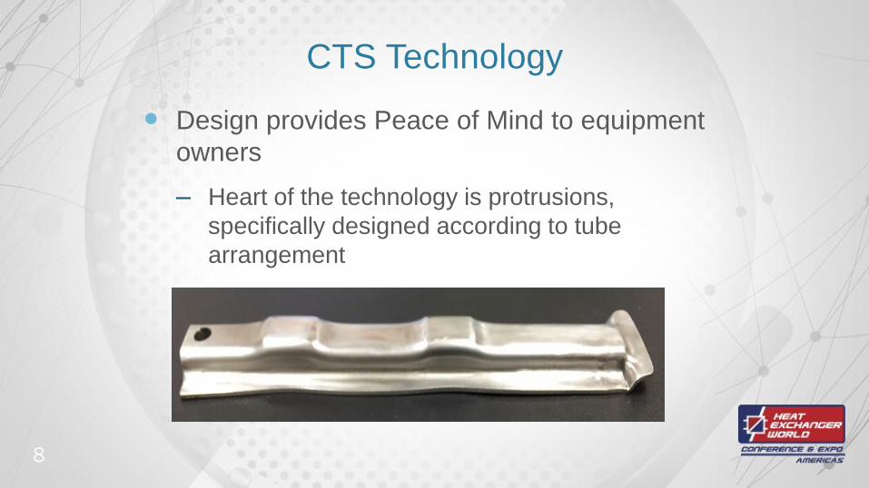
CTS Technology
Design provides Peace of Mind to equipment
owners
‒ Heart of the technology is protrusions,
specifically designed according to tube
arrangement
8

CTS Technology
Works with any tube
arrangement and
integrally finned tubes
In-Line
Arrangement
Staggered
Arrangement
9
Section A-A
Corrugation
Section B-B
ProtrusionA A
B
Protrusion
Tube 3
Tube 1
Tube 2
Tube 4
Tube 5
Original Position of Tube
B
A A
B BTube 3
Tube 1
Tube 2
Tube 4
Tube 5

CTS Technology - Installation
10
Most Vulnerable
Tube
CTS StakeWindow Region
Well-Supported
Region

CTS Technology in U-Bundles
Specially designed extension available for use in
u-tube bundles
‒ U-bend region is most vulnerable
‒ Tie Plates (current solution) only possible during
initial fabrication
‒ Bending tolerance leads to fabrication difficulties
11

Tie Plate Details
Plate(s) drilled with baffles
Cut into strips according to tube rows
Insert strips and secure during tube loading
Cut tubes at tubesheet face for uniform
projection
Oversizing holes would lead to vibration issues
12

Tie Plate Details
13
1. Plate Drilled and Cut Into Strips
Section A-A
Bent Tubes Usually Do Not Align
Properly with Hole Centers as Tube Bending Has a
Tolerance of About ± 1/16" On Radius
2. Each Strip Placed From Inside to
Outside as Tube Loading Takes Place; Strips are Welded to
Their Neighbors
Tie Plate
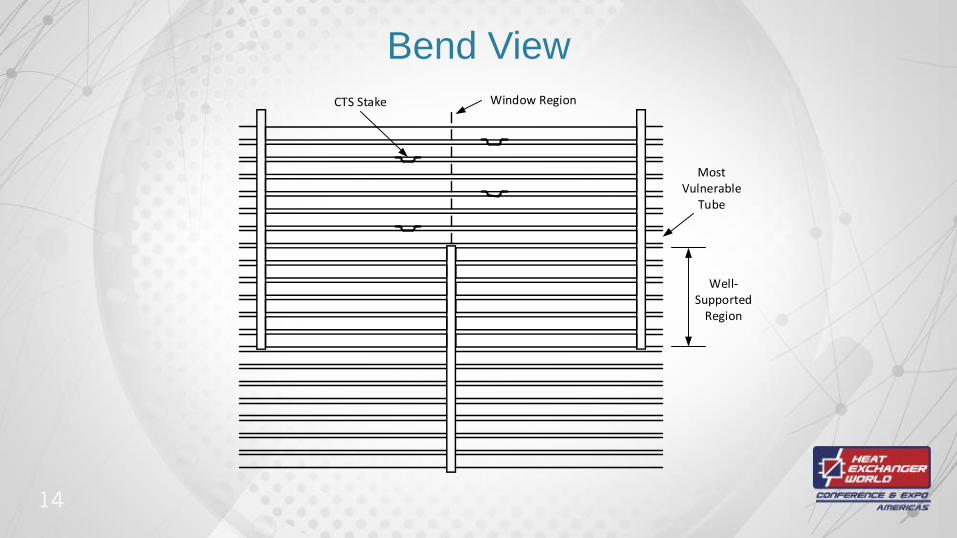
Bend View
14
Most Vulnerable
Tube
CTS Stake Window Region
Well-Supported
Region

CTS Technology in U-Bundles
15
Shown for Inline Tube
Arrangement
‒ Patent-Pending Design
‒ Clamps Squeeze Outermost
Tube to Ensure Positional
Integrity
‒ Reduced Thickness of “J-
Clamp” for Staggered Tube
Arrangement
L-Clamp
J-ClampModified CTS (Flat Area in
Outer Region)

Additional Applications
More Efficient Design for New Equipment
‒ Allows greater shellside velocity without vibration concern
‒ Unsupported tube length no longer a concern
Change in Metallurgy
‒ Decrease in corrosion allowance leads to thinner
tube wall
Capacity Creep
‒ Analyzed with HTRI Xist or Xvib
16

Conclusions
CTS technology offers a Peace-of-Mind Solution to
vibration problems
Protrusions are Heart of technology that ensure
positional integrity
Operations can improve with up-front design or
installation mid-life
Available in bend regions as improvement to industry
standard tie plate
17

Contact Information
Amar Wanni, Ph.D., Inventor
Russel Miller, P.E., Gulf Coast Exchanger
Vice-President
Jonathan Breaux, E.I.T., Gulf Coast Exchanger
Estimating Manager & Thermal Designer
‒ (+1)409.719.3895
18