new technologies robotic gmaw - matc.edu · ∕ minimum of welding spatter ... the built-in lsc...
TRANSCRIPT

New Technologies Robotic GMAW
Josh WilliamsonFronius USA LLC
Robotics Segment Manager

New GMAWTechnology
Low Spatter Control LSC Pulse Multi Control PMCTPSi Cold Metal Transfer CMT
2 Fronius International GmbH / SalesGuide 2017

3
NEW PROCESS: LSC – LOW SPATTER CONTROLEQUIPPED WITH THE NEW PENETRATION STABILIZER ASSISTANCE SYSTEM
Focus: less spatter & more
stability
∕ The result: A modified dip transfer arc process based
on the standard process, with an extremely high arc
stability for high-quality weld seams with minimal
spattering and increased deposition rate.
Less rework
∕ Optimal weld seam appearance –
perfect for visible weld seams
∕ Minimum of welding spatter
Characteristic packages
tailored to individual
needs
∕ LSC Root characteristics:
High arc pressure for better
root formation in forced weld layers
∕ LSC Universal characteristics:
For controlling the breaking of the
short circuit with gentler re-ignition
and fast adjustment responseConstant penetration
∕ Thanks to intelligent stabilizers

4 Fronius International GmbH / SalesGuide 2017
LSC Low Spatter Control

5
NEW PROCESS: LSC ADVANCED EQUIPPED WITH THE NEW PENETRATION STABILIZER ASSISTANCE SYSTEM
Focus: optimum weld properties and
process stability even with long
hosepacks
∕ The challenge: The longer the welding circuit (hosepack length),
the higher the inductivity generated, which affects the stability of
the welding process.
∕ The result: The built-in LSC Advanced module inside the power
source guarantees that the inductivity generated in the hosepack
is diverted. This ensures a more constant droplet detachment
less welding spatter.
No additional sensor line
needed
∕ Several welding operations can be
performed simultaneously on one
component
Maximum arc stability =
reproducible welding
results
∕ … thanks to intelligent stabilizers and
additional LSC Advanced module
∕ Own variant TPS 400i LSC Advanced
Even more stable

6 Fronius International GmbH / SalesGuide 2017
PMC Pulse Multi Control

Lower risk of burn-through
7

8
NEW PROCESS: PMC – PULSE MULTI CONTROLEQUIPPED WITH THE NEW PENETRATION & ARC LENGTH STABILIZER ASSISTANCE SYSTEMS
Focus: Penetration, heat input
& speed
∕ The result: A development based on the pulse process. The
high-speed data processing and precision detection of the
process status hugely improve droplet detachment. Perfect for
everyone who wants to weld even faster, yet stably and with a
constant penetration and less heat input.
Increased welding speed
∕ Reduced cycle time
∕ Increased productivity
Defined weave pattern
∕ Synchropulse – perfect for visible weld
seams
∕ Welding combinations of thin/thick sheets
9
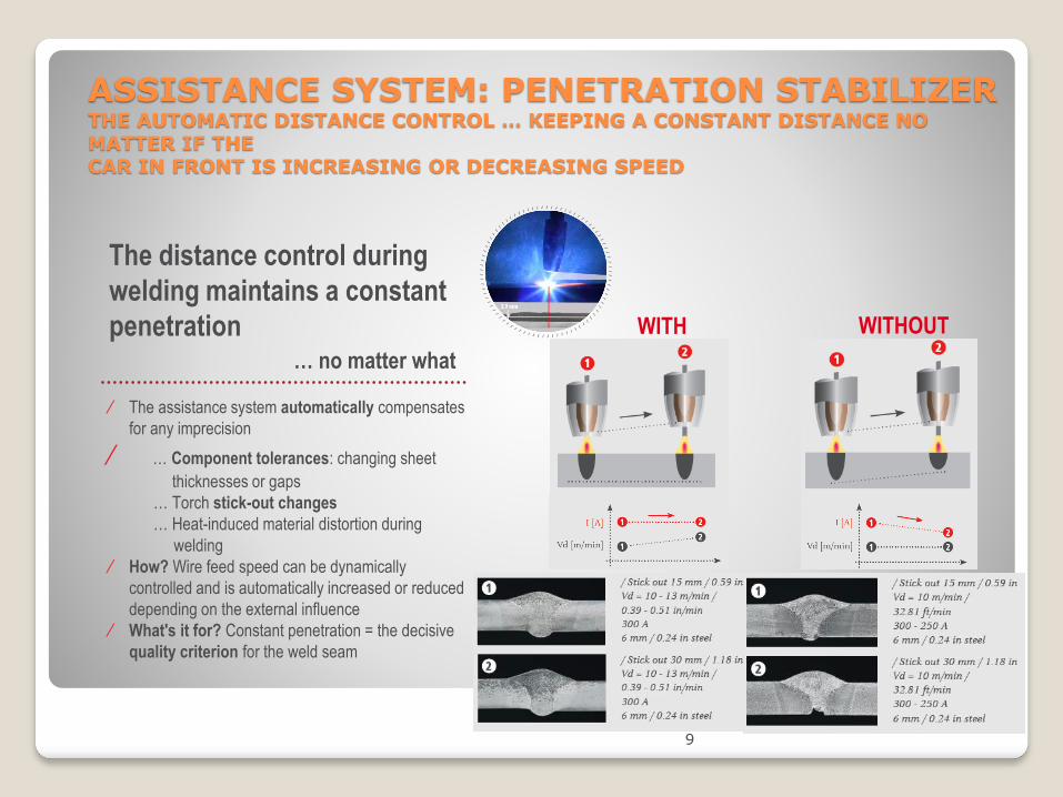
ASSISTANCE SYSTEM: PENETRATION STABILIZERTHE AUTOMATIC DISTANCE CONTROL … KEEPING A CONSTANT DISTANCE NO MATTER IF THE CAR IN FRONT IS INCREASING OR DECREASING SPEED
The distance control during
welding maintains a constant
penetration… no matter what
∕ The assistance system automatically compensates
for any imprecision
∕ … Component tolerances: changing sheet
thicknesses or gaps
… Torch stick-out changes
… Heat-induced material distortion during
welding
∕ How? Wire feed speed can be dynamically
controlled and is automatically increased or reduced
depending on the external influence
∕ What's it for? Constant penetration = the decisive
quality criterion for the weld seam
WITH WITHOUT

HIGHEST WELDING SPEED IN SHORT CIRCUIT
10

11
ASSISTANCE SYSTEM: ARC LENGTH STABILIZERTHE CRUISE CONTROL ASSISTANT ... KEEPING A CONSTANT SPEED BOTH UPHILL AND DOWN
The cruise control during welding
maintains a constant arc length,… no matter what
∕ The assistance system automatically compensates for any
imprecision
∕ … Dynamic, changing torch positions
… Component tolerances: changing sheet thicknesses or
gaps
… Uneven heat extraction
∕ How? The system keeps the arc at constant length
∕ What's it for? No need for the welding operation to be
interrupted or for manual readjustment of the arc length when
the torch position changes.
Quick parameter-finding focussed arc, faster welding
speed possible
WITH
WITHOUT

12
HIGHLIGHTS Exceptional weld
properties and maximum
precision
∕ TPS/i stands for perfect process stability and
the best welding performance, even under
changing external conditions.
∕ Highly dynamic real-time control for excellent
welding results
No more compromises: maximum
welding speeds can be combined
with a constant penetration, good
weld seam appearance and
excellent weld seam quality
Unimagined possibilities
joining complex materials
∕ The system can be updated at any time with
the latest Fronius developmentsAchieving reproducible quality
has never been easier
∕ Faster control reduces spatter and evens out
component tolerances to reduce rework,
reject rates and production downtimes to a
minimum
Rework can be reduced to a
minimum
∕ Increased productivity and lower costs

Principle pulsed arc
Arc length changes can appear during welding due to surface variations, increased travel speed
13
I/U

Principle PMC Arc + Arc length stabilizer
PMC adds dedicated short circuits to increase travel speed, penetration and arc stability.
14
I/U

Pulse vs Pmc using arc length stabilizer
15

16
Arc Length Stabilizer
/ Regardless of the welding position, the weld geometry or
interference, the properties of the controlled, faulted arc remain
the sameAL-Stab = 2AL-Stab = 0.5AL-Stab = 0

Arc length stabilizer set to 0.0
Arc length stabilizer settings
Arc length stabilizer set to 0.5
Arc length stabilizer set to 2.0
17
/ No dedicated short circuits
/ Good arc stability
/ Low travel speed
/ Applications:
- Cap passes
- 1F / PA position
- ……..
/ Low amount of dedicated short circuits
/ Increased arc stability
/ Increased travel speed
/ Applications:
- High deposition
- Fillet welds
- Out of position welds
- …….
/ Large amount of dedicated short
circuits
/ Increased arc stability
/ High travel speeds
/ Applications:
- Lap joints
- Vertical down welds
- ……..

18
COMBINATION: “AL-Stab” + “Penetration-Stabilizer”
12
PGM2851 / „Steel dynamic PMC“ / G3Si1 ø1,0mm / 82% Ar 18%CO2 / CTWD 10mm bis 20mm / Schweißgeschw. 100cm/min
/ Constant short arc + a constant
Penetration
/ Stabilizes the welding process when
disturbances occur, the welding seam
position or shape or the contact tube
distance changes
/ Example: Macro: G3Si1 ø1.0mm, 18%
CO2 Rest Ar
P-Stab = 5m/min, AL-Stab = 0.5
Pos.2: CTWD = 20mm Pos 1.: CTWD = 10 mm
vd = 23 m/min vd = 18 m/min
Penetration = 4.2mm Penetration = 4.2 mm

Galvanized steel with a chemical composite of either pure Zn (Zinc) or ZnFe (Zinc Iron) can be welded up to a Zinc coating thickness of ~15µm and a material thickness of 2 –3,5mm.
FUNDAMENTALS
19
Fronius USA LCC / Martin Willinger / PMC - Robotic Product Launch 2015 / April 2015 - v01

Pulsed arc vs Pulse multi control (PMC)
Conventional Pulsed Arc
◦ Travel speed: 1m/min (40ipm)
◦ WFS: 7m/min (275ipm)
◦ Gas: Ar + 10%CO2
PMC Universal
◦ Travel speed: 1m/min (40ipm)
◦ WFS: 7m/min (275ipm)
◦ Gas: Argon + 10%CO2
◦ Arc Length Stabilizer: 2.0
◦ Penetration Stabilizer: max.
20

Pulsed arc vs Pulse multi control (PMC)
Pulsed Arc
◦ Good outside seam appearance
◦ High amount of porosity
◦ Spatter ejection
◦ High heat input
PMC Universal
◦ Very good outside seam appearance
◦ Minimum porosity
◦ Low spatter ejection
◦ Less heat input
21

Shielding gas in comparison
Argon + 20% CO2
◦ More silicon islands
◦ Less wetting
◦ Increased porosity
◦ More spatter
Argon + 10% CO2
◦ Minimum silicon islands
◦ Nice wetting
◦ Low porosity
◦ Less spatter
22
Argon + 10% CO2
Argon + 20% CO2

PMC on galvanized steel
15µm thick galvanized steel plates. Vs: 1m/min (40ipm), Process; PMC + Arc Length Stabilizer and Penetration Stabilizer.
23

/ Flat position should be used to ensure
proper Zinc Oxide (ZnO) outgassing.
/ ZnO outgassing happens on the back
side of the weld.
Flat Position
Weld positions and behavior
/ Using a work angle of ~ 50º measured
from the top plate is recommended to
ensure proper ZnOoutgassing and good
wetting.
/ ZnO outgassing happens partly thru the
weld seam.
Horizontal Position
/ Maintaining a slight gap of ~ ¼ of the
material thickness helps the ZnO vapor to
escape.
/ If gaps are used they need to be
maintained consistent.
Gaps
24

Minimum porosity using pmc
Wire: 0.045” ER70S-3, Gas: Ar+ 5%CO2, Travel Speed 40ipm, Process: PMC Universal.
25

Seam appearance and macro using Pmc
Parameters
◦ Vs: 40ipm (1m/min)
◦ Wire Ø: 0.045“ (1,1mm)
◦ Wire alloy: ER70S-3 (~ G2Si1)
◦ Shielding gas: Ar + 10%CO2
◦ WFS: 275ipm (7m/min)
◦ Arc Length Stabilizer: 1.5 – 2.0
◦ Penetration Stabilizer: max. (395ipm / 10m/min)
◦ Material thickness: 2mm
26

CMT & CMT Mix

Technology
Cold Metal Transfer
With the CMT process, Fronius provides users with a highly dynamic welding process with the most stable arc in the world and minimal welding spatters. CMT is also no longer just “cold” but rather allows continuous regulation of heat input from cold to hot. This results in higher welding speeds and a broader range of applications with maximum welding quality.
28 Fronius International GmbH / SalesGuide 2017
TPS/i CMT PROCESS BENEFITS
◦ Highly dynamic wire control
◦ Extremely stable arc
◦ Wider process window – up to the end of the intermediate arc
◦ Most stable process with minimal spattering (up to 200 cm/min)
29

CMT Correction Parameter
30
CMT process parameter
The correction of the arc-length and the arc-
dynamic at the CMT process is generated by an
adjustment of the wire feed speed and the
welding current profile.

CMT arc length correction
31
Arc length correction
The length of the arc in the arc burning period is adjusted
by the time of the backward and forward movement. This
wire speed corrections in length and height are specific for
synergic line.
Unit -
Range -10 to + 10
Default 0
Application of the arc length correction
Positive correction causes a longer backward movement
period and a reduced forward feeding speed for the wire
electrode, what results in an extension of the arc within the
CMT process period.
Negative correction gives a shorter arc length by reducing
the time of the backward movement and increasing the
amount of the forward feeding speed of the wire electrode.

CMT arc length correction
32

CMT Dynamic correction
33
Dynamic Correction
This correction represents the dynamic or short-circuit behavior of
the CMT drop transfer. The current-level at the point of reigniting in
a CMT period and the acceleration ramp of the wire feeder after the
point when the short circuit occurs, are adjusted with this correction.
Unit -
Range -10 to + 10
Default 0
Application of the dynamic correction
The negative correction rises the current level at the point of
reigniting in a period and increases the acceleration ramp of the
wire feed speed. As a result the drop transfer time is shortened, the
process frequency is increased and CMT feels to be more intense.
The positive correction lowers the current level at reigniting and
gives a reduced acceleration ramp for the wire feeder. This results
in a longer duration of the drop transfer, the process frequency is
lowered and CMT feels to be smoother.

CMT Dynamic correction
34

CMT Dynamic Correction Heat Input
control
35

CMT Mix Correction & Parameter setting

CMT Mix
37
CMT Mix high power time correction
38

CMT Mix low power time correction
39

All information is without guarantee in spite of careful editing - liability excluded.
Intellectual property and copyright: all rights reserved. Copyright law and other laws protecting intellectual property apply to the not otherwise marked content of this presentation respectively documents (texts, pictures, graphics,
animations etc.). It is not permitted to use, copy or alter the content of this presentation for private or commercial purposes without express authorisation from Fronius.