new silent alert fire safe systemsilent-alert.co.uk/firesafe/download/sa3000 - fire safe -...
TRANSCRIPT

SILENT ALERT SA3000 FIRE SAFE MANUAL 06 June 2012
Designed & Manufactured by Clofield Limited Free Technical Helpline 0800-387-397 www.silent -alert.co.uk
1
New Silent Alert Fire Safe System
TECHNICAL MANUAL
This manual covers the
FSTX-2225-EU - Fire Alarm Interface PG3A-2204-EU - Pager Unit - Fire Safe Compatible
FSCH-2226-IN - Fire Safe Charger or CH3A-2205-IN – Alarm Clock Charger
The Fire Safe Interface Panel contains electrostatic discharge sensitive components. Observe antistatic precautions whilst ever the cover is removed.
SILENT ALERT SA3000 FIRE SAFE MANUAL 06 June 2012
Designed & Manufactured by Clofield Limited Free Technical Helpline 0800-387-397 www.silent -alert.co.uk
2
TECHNICAL SPECIFICATION
Introduction
The Silent Alert Fire Safe System alerts people who are deaf when a fire alarm is activated; it comprises a Fire Alarm Interface and one or more vibrating pager units. The Fire Alarm Interface links to a fire alarm panel via a volt free relay and incorporates a radio transmitter. When the fire alarm is activated the transmitter within the Fire Alarm Interface sends out a coded radio signal. When a Pager receives this signal it vibrates and lights a fire key on the pager display. The system is designed to comply with all relevant parts of BS5839-1 2002 & EN54-2 and MUST be installed by a competent person as defined in BS5839-1 2002.
Installation Training
Installation training is available; please call us on 01246-260045 for more details.
Fire Safe Interface Panel
Part Number: FSTX-2225-EU Dimensions: H300mm x W240mm x D100mm Weight: Without Battery 1.90 KG - With battery 4.5KG Material: Polycarbonate self-extinguishing enclosure. Protection: Water resistant Power Supply: 240v AC 50 Hz Battery back up: 12volt lead acid 7Ah (Yuasa Type NP7-12) Dimensions (H100mmxW150mmxD65mm) Alarm Panel feed to Fire Safe Panel: Normal condition 5-30 Volts DC this can be taken from the leads within the panel. Grounded in alarm mode via an integral OPTO isolated voltage fed relay. Fault signal to Fire Panel: Via an integral normally open or normally closed volt free relay. Fault conditions: Mains failure, battery removal or charge failure,
main PCB failure, radio failure Radio Compliance: In accordance with EN300 220-1. Radio Licence: Licence Exempt Range: Up to 1000m in open air
Pager Unit
Part Number: PG3A-2204-EU MKIII Dimensions: H63mm x W82mm x D26mm (Excluding belt clip) Weight: 74gms Material: Impact resistant ABS Power Supply: Integral NiMH 6Volt rechargeable battery pack. Charger: Intelligent boost, trickle and maintenance charging. Fault conditions: Low battery & radio failure. Radio Compliance: In accordance with EN300 220-1. Radio Licence: Licence Exempt. Range: Up to 1000m in open air. Other: Integral field strength / data validation meter for system commissioning.
SILENT ALERT SA3000 FIRE SAFE MANUAL 06 June 2012
Designed & Manufactured by Clofield Limited Free Technical Helpline 0800-387-397 www.silent -alert.co.uk
3
INSTALLATION
Preliminary Radio Coverage Test
A preliminary radio coverage test is normally conducted prior to installation to ensure total coverage throughout a building. It is recommended that a further radio coverage test is performed prior to permanently securing the Fire Safe Panel to a wall in case it needs to be relocated. The Fire Safe panel should be mounted temporarily to a wall at between 1.5 and 1.75 meters from the ground away from large metal objects and lift shafts. For best results locate the panel central to the building. In multi-storey buildings penetrations through steel re-enforced concrete floors may be poor. In these situations coverage would be improved if the panel is located one floor above ground level to provide coverage over three floors or two levels above ground level to cover four floors. In-building coverage will vary from building to building therefore it is essential that a full and thorough radio coverage test is conducted. The range test procedure detailed later under the heading Site Survey should be followed. If it is found that the coverage is inadequate then additional Fire Safe Interfaces may need to be added. In this case it will be necessary to change the signal patterns for each panel to ensure there are no standing wave problems. This aspect is covered in more detail under the heading The use of more than one Fire Safe Panel below.
Power Supply
It is necessary to supply the Interface panel with a dedicated mains supply (220-240v AC 50 Hz) via its own unswitchable fused spur. The mains terminal block is located at the bottom left hand side of the main PCB and is marked Earth (top) Neutral (middle) Live (bottom). The Panel will also require a 12 Volt lead acid 7Ah back-up battery (Yuasa Type NP7-12) Dimensions (H100mmxW150mmxD65mm). It is necessary to connect the battery to the two wires with crimped connectors, before connecting the mains to avoid a fault condition.
SILENT ALERT SA3000 FIRE SAFE MANUAL 06 June 2012
Designed & Manufactured by Clofield Limited Free Technical Helpline 0800-387-397 www.silent -alert.co.uk
4
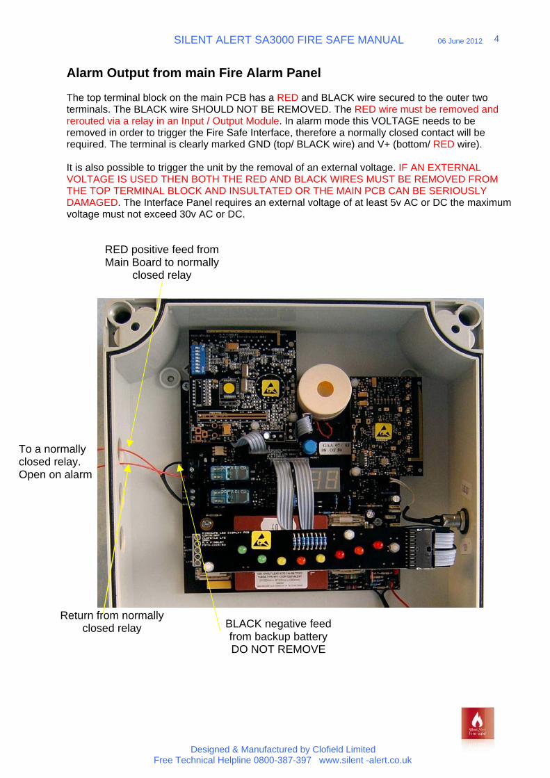
Alarm Output from main Fire Alarm Panel
The top terminal block on the main PCB has a RED and BLACK wire secured to the outer two terminals. The BLACK wire SHOULD NOT BE REMOVED. The RED wire must be removed and rerouted via a relay in an Input / Output Module. In alarm mode this VOLTAGE needs to be removed in order to trigger the Fire Safe Interface, therefore a normally closed contact will be required. The terminal is clearly marked GND (top/ BLACK wire) and V+ (bottom/ RED wire).
It is also possible to trigger the unit by the removal of an external voltage. IF AN EXTERNAL VOLTAGE IS USED THEN BOTH THE RED AND BLACK WIRES MUST BE REMOVED FROM THE TOP TERMINAL BLOCK AND INSULTATED OR THE MAIN PCB CAN BE SERIOUSLY DAMAGED. The Interface Panel requires an external voltage of at least 5v AC or DC the maximum voltage must not exceed 30v AC or DC.
Return from normally
closed relay
RED positive feed from Main Board to normally
closed relay
BLACK negative feed from backup battery DO NOT REMOVE
To a normally closed relay. Open on alarm
SILENT ALERT SA3000 FIRE SAFE MANUAL 06 June 2012
Designed & Manufactured by Clofield Limited Free Technical Helpline 0800-387-397 www.silent -alert.co.uk
5
Fault condition from Fire Safe Panel
The Fire Safe panel has a fault output to the main Fire Alarm Panel provided via the middle terminal block. A fault condition on the Fire Safe Panel will cause a relay to be closed that will create an open circuit between common and normally closed (N/C) and a closed circuit between normally open (N/O) and common.
A fault alarm will be given in the following conditions:
Mains failure Battery charge failure or removal Loss of radio signal Main PCB failure
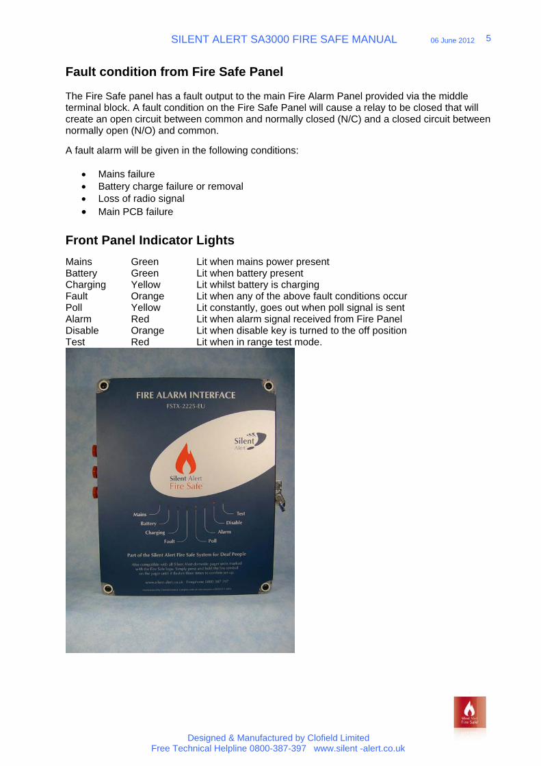
Front Panel Indicator Lights
Mains Green Lit when mains power present Battery Green Lit when battery present Charging Yellow Lit whilst battery is charging Fault Orange Lit when any of the above fault conditions occur Poll Yellow Lit constantly, goes out when poll signal is sent Alarm Red Lit when alarm signal received from Fire Panel Disable Orange Lit when disable key is turned to the off position Test Red Lit when in range test mode.
SILENT ALERT SA3000 FIRE SAFE MANUAL 06 June 2012
Designed & Manufactured by Clofield Limited Free Technical Helpline 0800-387-397 www.silent -alert.co.uk
6
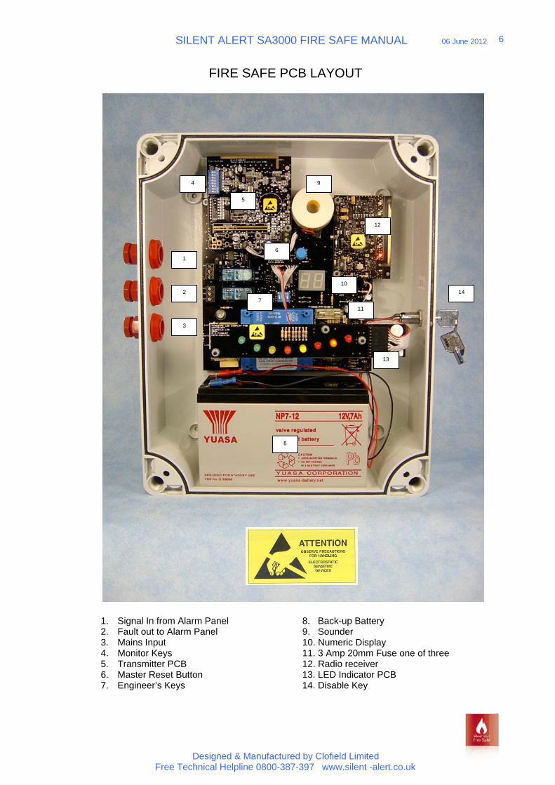
FIRE SAFE PCB LAYOUT
1. Signal In from Alarm Panel 8. Back-up Battery2. Fault out to Alarm Panel 9. Sounder3. Mains Input 10. Numeric Display4. Monitor Keys 11. 3 Amp 20mm Fuse one of three5. Transmitter PCB 12. Radio receiver6. Master Reset Button 13. LED Indicator PCB7. Engineer’s Keys 14. Disable Key
4
10
5
6
1
2
3
7
9
8
11
12
13
14

SILENT ALERT SA3000 FIRE SAFE MANUAL 06 June 2012
Designed & Manufactured by Clofield Limited Free Technical Helpline 0800-387-397 www.silent -alert.co.uk
7
OTHER COMPONENTS
Pager Unit (PG3A-2204-EU MKIII)
Pager front showing key pad Pager back showing key switches
Fire Safe Charger Unit (FSCH-2226-IN) with Power Supply (PS3A-2207-UK)
Alarm Clock Charger (CH3A-2205-IN) with Power Supply (PS3A-2207-UK)
SILENT ALERT SA3000 FIRE SAFE MANUAL 06 June 2012
Designed & Manufactured by Clofield Limited Free Technical Helpline 0800-387-397 www.silent -alert.co.uk
8
SYSTEM SETUP
Setup
Fire Safe Interface Panel
1. Remove the front cover using a flat bladed screwdriver by loosening the four capturedplastic screws in each corner.
2. The Interface contains a number of components that are susceptible to electrostaticdamage. Observe antistatic precautions whilst ever the front cover is removed and avoidtouching the surface of any of the PCB’s.
3. Locate the Interface panel next to the main fire alarm panel at 1.5m –1.75m from theground. Avoid locating the panel close to large metal objects and lift shafts.
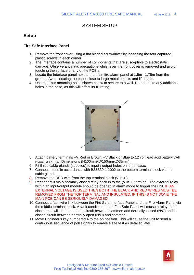
4. Use the Four mounting holes shown below to secure to a wall. Do not make any additionalholes in the case, as this will affect its IP rating.
5. Attach battery terminals +V Red or Brown, –V Black or Blue to 12 volt lead acid battery 7Ah(Yuasa Type NP7-12) Dimensions (H100mmxW150mmxD65mm).
6. Fit three cable glands (supplied) to input / output holes on left of case.7. Connect mains in accordance with BS5839-1 2002 to the bottom terminal block via the
cable gland.8. Remove the RED wire from the top terminal block (V in + ).9. Reconnect it via a normally closed relay back in to the (V in +) terminal. The external relay
within an input/output module should be opened in alarm mode to trigger the unit. IF ANEXTERNAL VOLTAGE IS USED THEN BOTH THE BLACK AND RED WIRES MUST BEREMOVED FROM THE TOP TERMINAL AND INSULATED. IF THIS IS NOT DONE THEMAIN PCB CAN BE SERIOUSLY DAMAGED.
10. Connect a fault wire link between the Fire Safe Interface Panel and the Fire Alarm Panel viathe middle terminal block. A fault condition on the Fire Safe Panel will cause a relay to beclosed that will create an open circuit between common and normally closed (N/C) and aclosed circuit between normally open (N/O) and common.
11. Move Engineer’s key numbered 4 to the on position. This will cause the unit to send acontinuous sequence of poll signals to enable a site test as detailed later.
SILENT ALERT SA3000 FIRE SAFE MANUAL 06 June 2012
Designed & Manufactured by Clofield Limited Free Technical Helpline 0800-387-397 www.silent -alert.co.uk
9
Pager Unit
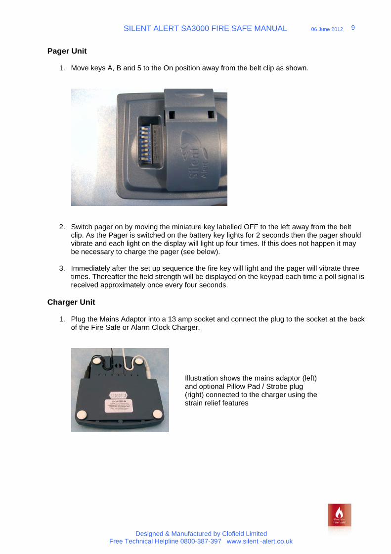
1. Move keys A, B and 5 to the On position away from the belt clip as shown.
2. Switch pager on by moving the miniature key labelled OFF to the left away from the beltclip. As the Pager is switched on the battery key lights for 2 seconds then the pager shouldvibrate and each light on the display will light up four times. If this does not happen it maybe necessary to charge the pager (see below).
3. Immediately after the set up sequence the fire key will light and the pager will vibrate threetimes. Thereafter the field strength will be displayed on the keypad each time a poll signal isreceived approximately once every four seconds.
Charger Unit
1. Plug the Mains Adaptor into a 13 amp socket and connect the plug to the socket at the backof the Fire Safe or Alarm Clock Charger.
Illustration shows the mains adaptor (left) and optional Pillow Pad / Strobe plug (right) connected to the charger using the strain relief features
SILENT ALERT SA3000 FIRE SAFE MANUAL 06 June 2012
Designed & Manufactured by Clofield Limited Free Technical Helpline 0800-387-397 www.silent -alert.co.uk
10
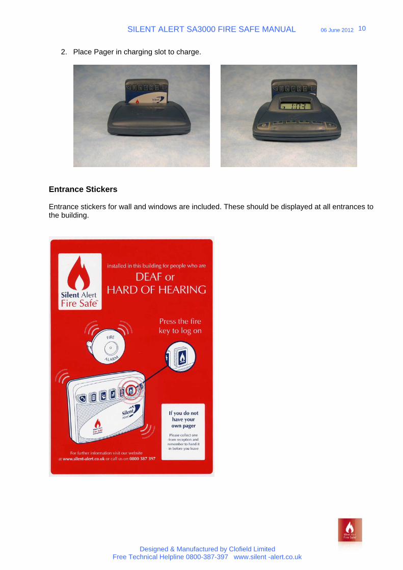
2. Place Pager in charging slot to charge.
Entrance Stickers
Entrance stickers for wall and windows are included. These should be displayed at all entrances to the building.
SILENT ALERT SA3000 FIRE SAFE MANUAL 06 June 2012
Designed & Manufactured by Clofield Limited Free Technical Helpline 0800-387-397 www.silent -alert.co.uk
11
Site Survey
Radio coverage test
1. Ensure the Fire Safe is in range test mode. Engineer’s key 4 in the on position.2. Ensure the Pager is charged and in range test mode, as above.3. Walk around the building with the pager. As the pager receives a poll signal, the keys on the
pager will light. The highest signal strength will light the telephone key the lowest the batterykey. It is essential that one of the keys lights up during each transmission, within the area tobe covered.
4. It is possible to add additional Interface Panels on larger sites.5. Switch Engineer’s Key 4 on the Fire Safe Interface to the OFF position.6. Switch the Pager off, move key B to the OFF position, switch the pager on again. The pager
will go through its normal start up routine.7. The fire key will flash and the pager will vibrate three times when the pager receives the first
poll signal from the Interface Panel, this can take up to 4 minutes 45 seconds.
The use of more than one Fire Safe Panel
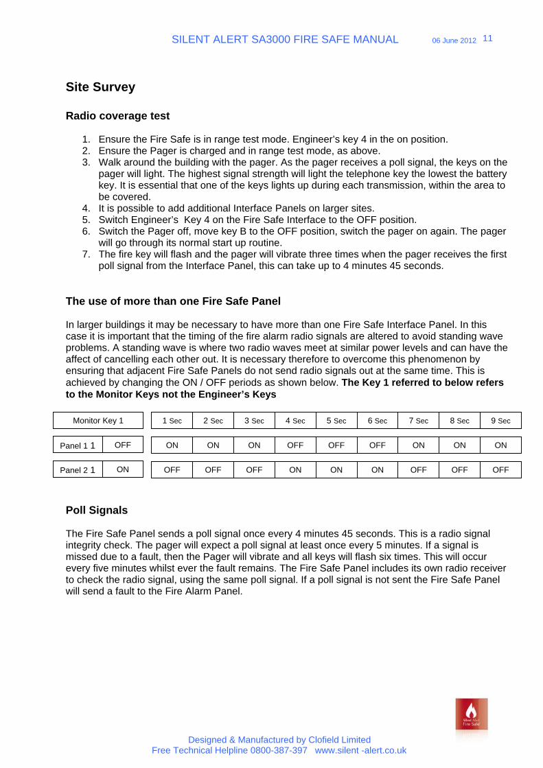
In larger buildings it may be necessary to have more than one Fire Safe Interface Panel. In this case it is important that the timing of the fire alarm radio signals are altered to avoid standing wave problems. A standing wave is where two radio waves meet at similar power levels and can have the affect of cancelling each other out. It is necessary therefore to overcome this phenomenon by ensuring that adjacent Fire Safe Panels do not send radio signals out at the same time. This is achieved by changing the ON / OFF periods as shown below. The Key 1 referred to below refers to the Monitor Keys not the Engineer’s Keys
Poll Signals
The Fire Safe Panel sends a poll signal once every 4 minutes 45 seconds. This is a radio signal integrity check. The pager will expect a poll signal at least once every 5 minutes. If a signal is missed due to a fault, then the Pager will vibrate and all keys will flash six times. This will occur every five minutes whilst ever the fault remains. The Fire Safe Panel includes its own radio receiver to check the radio signal, using the same poll signal. If a poll signal is not sent the Fire Safe Panel will send a fault to the Fire Alarm Panel.
Panel 2 1
Panel 1 1
1 Sec 2 Sec 3 Sec 4 Sec 5 Sec 6 Sec 7 Sec 8 Sec 9 SecMonitor Key 1
ON ON ON OFF OFF OFF ON ON ONOFF
OFF OFF OFF ON ON ON OFF OFF OFFON
SILENT ALERT SA3000 FIRE SAFE MANUAL 06 June 2012
Designed & Manufactured by Clofield Limited Free Technical Helpline 0800-387-397 www.silent -alert.co.uk
12
Daily Use
The Pager Unit can be placed at reception on charge permanently. Both the Fire Safe Charger and Alarm Clock Charger have intelligent charging circuits that ensure the Pager is not overcharged.
If a visitor leaves the building without returning the pager to reception the pager will vibrate and all lights will flash 6 times within 4 minutes 45 seconds to remind the user. This sequence will repeat whilst ever the pager is out of range of the system.
Visitors who have their own Silent Alert Fire Safe Compatible Pagers can log onto the system by pressing the fire key on their own pager as they enter the building.
Annual / Six Monthly Maintenance
1. The lead acid battery should be checked and replaced as necessary.
2. The site survey should be repeated with each Pager.
3. The Charger power supply should be PAT tested annually.
4. Check for obvious signs of wear and tear to the Pager/s, Charger/s and Fire Alarm InterfacePanel.
5. During the Fire Alarm system test check that the Fire Safe Panel goes into alarm mode,indicated by the red alarm light on the front panel and that a fire signal is received by allpagers.
6. Fault condition test should be carried out as follows:
- Remove mains from Fire Safe Panel – Observe green mains indicator goes out and that the orange fault light comes on.
- Reinstate mains power and disconnect battery lead – Observe green battery and yellow charging lights go out, sounder activates and the red fault light comes on.
Master Reset & Numeric Display Diagnostics
Master Reset
The System will recover from a fault condition when the fault has been rectified. This however can take a number of seconds. The Master Reset button can be used to clear fault conditions more quickly.
Numeric Display Diagnostics
SILENT ALERT SA3000 FIRE SAFE MANUAL 06 June 2012
Designed & Manufactured by Clofield Limited Free Technical Helpline 0800-387-397 www.silent -alert.co.uk
13
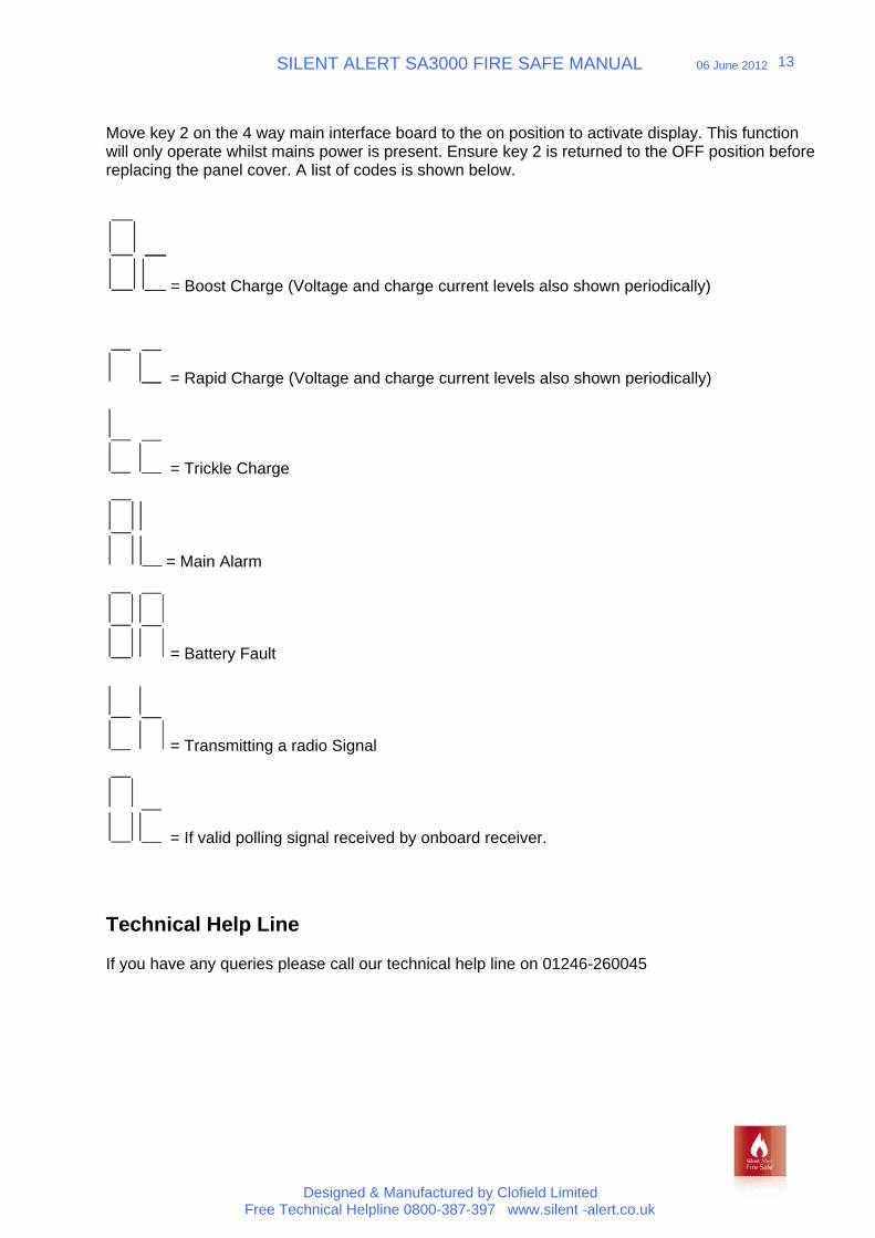
Move key 2 on the 4 way main interface board to the on position to activate display. This function will only operate whilst mains power is present. Ensure key 2 is returned to the OFF position before replacing the panel cover. A list of codes is shown below.
= Boost Charge (Voltage and charge current levels also shown periodically)
= Rapid Charge (Voltage and charge current levels also shown periodically)
= Trickle Charge
= Main Alarm
= Battery Fault
= Transmitting a radio Signal
= If valid polling signal received by onboard receiver.
Technical Help Line
If you have any queries please call our technical help line on 01246-260045