new limitation change to. 6. reception from 6 to 30 mhz on this 2-6 mhz antenna is also ......
TRANSCRIPT

UNCLASSIFIED
AD NUMBER
AD872808
NEW LIMITATION CHANGE
TOApproved for public release, distributionunlimited
FROMDistribution authorized to U.S. Gov't.agencies and their contractors;Administrative/Operational Use; Jun 1970.Other requests shall be referred to NavalElectronics Lab., San Diego, CA 92152.
AUTHORITY
Naval Electronics Lab. ltr, 22 Aug 1974
THIS PAGE IS UNCLASSIFIED
m
_ _ _ _ _ _ _
z
(60
ZI
00
SHIPBOARD HF RECEIVING ANTENNA SYSTEM:1 ESIGN CRITERIALL-i
'I.E. Gustafson and W.M. Chase • Research and Development • 2 June 1970
DDC
STAT•V.EMIT #2 UNCLASSIFIED
This document to sub.ect to sPecir!1 export controls and eachtransrmitt2l- to fc'roig:n go-:urawent-L or foreign nationals may be
NAVAL ELECTRONICS LABORATORY CENTERSAN DIEGO, CALIFORNIA 92152
iii
THIS DOCUMENT IS SUBJECT TO SPECIAL EXPORT CONTROLS ANDEACH TRANSMITTAL TO FOREIGN GOVERNMENTS OR FOREIGNNATIONALS MAY BE MADE ONLY WITH PRIOR APPROVAL OF THENAVAL ELECTRONICS LABORATORY CENTER, SAN DIEGO, CALIF.92152.
PROBLEM
Determine critical factors related to hf receiving-system design, suchas antenna coupling and efficiency, multicoupler performance, receiver over-load effects, transmitter noise, and atmospheric noise. Relate these factorsto arrive at a methodology for evaluation and optimization.
RESULTS
1. Acceptable system sensitivity with several receiving-antenna designsis compromised by the necessity for receiver protection from local trans-missions.
2. An R-1051D receiver fed through an AN/SRA-49 multicoupler froma 25-foot trussed whip meets or exceeds sensitivity requirements.
3. Receive-transmit minimum frequency spacing of 272 percent can-not be provided by this receiving system with an assumed 20 dB antennadecoupling.
4. Although practical isolations with broadband antennas probablypreclude 21/2 percent minimum frequency separation, comparison ofspecific antenna designs can be made by using the developed analytical model.
5. With slight increase in frequency-spacing requirements from thatwith separate antennas, a 2-6 MHz transmitting antenna can be used forreception by decoupling between the antenna bus and the AN/SRA-49multicoupler.
6. Reception from 6 to 30 MHz on this 2-6 MHz antenna is alsopossible if directivity and impedance are satisfactory.
7. Decoupling demands may not be consistent with adequate systemsensitivity above 6 MHz.
8. Because 5-percent minimum separation to other transmitter fre-quencies is stipulated, a transmit/receive switch at the transmitter outputwill also support the receive mode in simplex operation.
9. The best choice from several coupling options for simplex-casereception on the transmitting antenna is controlled decoupling at the trans-mitter output without additional filtering.
10. Since antenna diversity provides a 3/1 error-rate reduction in copy-ing multichannel broadcast, it is important that design options provide morethan one receiving antenna.
RECOMMENDATIONS
I. Use the results developed here as guidance in designing shipboard re-ceiving antennas and in evaluating proposed designs.
2. Use the results developed here to assess possible improvements inmulticouplers and receivers to eliminate deficiencies shown to be of impor-tance.
3. Continue design-feasibility studies at NELC to determine the poten-tial of the cc~n'bination antenna receive-transmit system (CARTS).
4. Conduct design studies of other common transmit/receive antennaapproaches discussed in the report, to determine their technical andoperational advantages for simplex operation.
S. Emphasize development and use of multiple receiving-antenna cap-abilities for antenna diversity applications.
ADMINISTRATIVE- INFORMATION
Work was performed under SF 14.222.004, Task 13950 (NELCB 164) by members of the Radio Technology Division. The report coverswork from October 1969 to April 1970, and was approved for publication2 June 1970.
r2

CONTENTS
INTRODUCTION . . . page 5
REQUIRED RECEIVING-SYSTEM CAPABILITY. . . 6
RECEIVING-SYSTEM LOSS BUDGET . . . 7
Receiver Sensitivity . . . 7Receiving Multicoupler Efficiency . . . 7Typical Receiving-Antenna Efficiency . 8System Loss Budget. . . 9
RECEIVING ON TRANSMITTING ANTENNA. . . 10
RECEIVER PROTECTION CONSIDERATIONS . . . 13
MINIATURE RECEIVING ANTENNAS. . . 17
DIVERSITY-RECEPTION CONSIDERATIONS. . . 17
CONCLUSIONS . . . 17
RECOMMENDATIONS . . . 19
REFERENCES . . . 20
TABLES
1 Quasi-minimum Atmospheric Noise Levels . . . 72 Electrical Characteristics of AN/SRA-38/39/40 and -49
Multicouplers . . . 83 Receiving-System Loss Budget. . . 94 Loss Budget for Receiver Coupled at Transmitter Output . . . 135 Receiver (R- 105 1 D) Cross-Modulation Parameters, Separate
Receiving Antenna . . . 146 Receiver (R- 105 1D) Cross-Modulation Parameters, Coupled
at Transmitter Terminals . . . 16
3
ILLUSTRATIONS
I Common transmit/receive antenna with decoupling at antennabus. 10
2 Common transmit/receive antenna with connection at-transmitteroutput . . 12
3 Receiver-transmitter spacing requirements based on cross-modulationlimitations for AN/SRA-49, R 1051 receiving system . . . 15
4

INTRODUCTION
Work has been underway at NELC to develop criteria for antennasystem design, for a guide in specific antenna developments. This reportcovers several aspects of receiving antenna subsystem design, the interdepen-dencies related to specific design choices, and applicable criteria for derivinga near-optimum subsystem design. This work is closely related to currentanalytical studies under the Shipboard Integrated Electronics System (SIES)program and some of the material used in the report was derived underTask E of the SIES study. The primary emphasis in the report is in the areaof antenna-related criteria, but there are several aspects of compatibilityinvolved in antenna and multicoupler design choices. These must be con-sidered when deriving antenna system criteria.
The shipboard environment imposes severe requirements on design ofradio frequency (rf) portions of the hf communications complex. The spacegenerally available for antennas is amidships and covers a length of onlyabout 200 to 300 feet. Design of the 2-32 MHz portion of the communica-tions suit (referred to as hf) must take into account that this very limitedarea is about one-half wavelength in extent at 2 MHz. Spacings from majorship structures that act as parasitic radiators are very small and this resultsin major coupling problems. Coupling between the numerous communica-tions antennas that must be placed in this small area is very high. This leadsto particularly difficult problems in receiving-system design because of thevery large voltages that exist on receiving antennas as a result of the nearbytransmitting antennas. Levels up to 100 volts can be expected and must beallowed for in protecting the receiving system from burnout and from otherdegrading phenomena such as overload desensitization, cross-modulation, andintermodulation.
Some idea of the design difficulty can be obtained from comparingthe normal receiving-system threshold to transmitter power levels. Typicaltransmitter power levels are 1 kW (30 dBW) while typical receiving thresholdis about 1 microvolt (-137 dBW). This leaves a differential of 167 dB. Thesmall area leads to a nominal transmit-to-receive antenna isolation of about20 dB.if care is taken to most effectively use the available space. Even withseparate antennas the power differential is 147 dB. The receiving systemmust operate with this very great power differential. Receiver parametersrelated to interfering signals are usually stated in terms of 0.1 to 1.0 voltwhile expected levels on the receiving antenna are 10 to 100 volts. Muchadditional filtering is required to reach a tenable design, and this is usuallyobtained in the receiving multicoupler.
There are other factors related to receiving-system design, such asintermodulation, expected atmospheric noise level, transmitter noise andspurious signal levels, and receiver spurious responses. All of these affectto some degree the design requirements for receiving antennas. It is thepurpose here to discuss receiving-antenna design approaches in relation to thecomplex dependencies of the above factors. The design compromises will bediscussed in quantitative terms in an attempt to provide design guidance forfuture development work and for antenna systems design. Transmitter noise
5

was not included, since there is a possibility of reducing this noise throughredesign or modification. It was considered unwise to allow this deficiencyto influence receiving subsystem optimization approaches at this time.
REQUIRED RECEIVING-SYSTEM SENSITIVITY
In hf systems design, atmospheric noise is normally the limiting fac-tor in receiving-system capability. This is not necessarily the case in ship-board systems but it is necessary to assess the magnitude of atmosphericnoise as one of the limiting factors. This source can then be compared toother potential interference sources to determine the critical one for anyspecific design approach. The field intensity of atmospheric noise varieswith geographical location, frequency, time of day, and season. Means ofpredicting noise values are contained in reference I (see list at end of report).
The large number of possible situations regarding atmospheric noiselevels precludes taking into account all of the variables for use in generalizedsystems design as treated in this report. A different approach is required toreduce the complexity to reasonable bounds. The two major points to beconsidered are: (I) that atmospheric noise should override receiver noise,i.e., receiving-equipment sensitivity should not be limiting; and (2) thatideally the locally generated interference level should be less than the atmos-pheric noise level so as not to place further restrictions on system sensitivity.In either case the most difficult situation is that for very low atmosphericnoise levels. However, to design for the lowest possible level expected at anytime and at any place results in extreme overdesign and probably cannot beachieved. Accordingly, a compromise position has been established in whichquasi-minimum atmospheric noise levels have been determined. Two sourcesof information were used to derive these values: (I) a comprehensive exami-nation of expected noise at many locations and for all seasons, using datafrom National Bureau of Standards noise-measurement program; 2 and (2)shipboard measurements in the San Diego area (a typically low-noise region)?'These quasi-minimum values are based on judgement rather than on specificcomputations and they represent typical low-noise periods in some of thelower noise regions but not in the Arctic. This does not assure that atmos-pheric noise will not at times drop below receiver noise. There are tworeasons for accepting this design compromise: (I) practical limits on receiver,nitlticoupler, and receiving-antenna noise factors will probably precludeappreciable improvements in system sensitivity: and (2) the fact that atmos-pheric noise drops lower at times will not compromise system performancefor ground-wave propagation and will actually enhance it most of the time.Table I lists the quasi-minimnum design levels for representative frequencies.It is clear that extreme sensitivity in the receiving system is not required,since a total noise figure of 20 dB at 30 MHz or 52 dB at 2 MHz is tolerable.As will be shown later, this does not mean that very poor receivers are
6

TABLE 1. QUASI-MINIMUM ATMOSPHERIC NOISELEVELS, dB ABOVE THERMAL (KTB)
2 MHz 4 MHz 10 MHz 30 MHz
52 dB 42 dB 32 dB 20 dB
acceptable, since filtering required to protect the receivers must use a goodportion of this allowable loss budget. Also there is normally insufficientroom aboard ship for fully efficient receiving antennas at the lower end ofthe hf spectrum and some of the loss budget is required to cover this deficiency.
RECEIVING-SYSTEM LOSS BUDGET
RECEIVER SENSITIVITY
It is possible to build hf receivers with a noise figure of 4 to 6 dBwhen this is the prime requirement. However, aboard ship this is generallynot possible because several other factors must be considered in the designand these affect noise figure. The primary factor is that of adjacent strongsignal rejection and most shipboard receivers are designed with two tunedstages ahead of the first rf amplifier. This adds loss to the system and resultsin a practical noise-figure limit of about 9 to 10 dB. When consideration isgiven to maintainability of good sensitivity in the field, a noise figure ofpractical design is about 12 dB. Well maintained R- 105 1 /URR receivers nowin use have a noise figure of about 12 dB. For purposes of further systemcomputations this value will be used as typical. If results show a significanttotal system deficiency, the problem of the receiver noise figure will be re-examined to determine the practicability of small improvements in this area.The noise figure as used above is deficient in comparison to that of a perfectreceiver operating at room temperature. In other words, a perfect receiverwould have a background noise equivalent to thermal noise (KTB).
RECEIVING MULTICOUPLER EFFICIENCY
Receiving multicouplers must provide a high rejection to the highvoltages induced by local transmitters. This requires several stages of filtering.and losses increase in proportion to the number of filter stages (assuming aconstant ratio of loaded to unloaded Q). It is possible to keep losses lowerby using a smaller number of stages and accepting a much Ilarger guard hand
7

between transmit and receive frequencies. Alternately, a much larger filter'oluinie will result in lower losses for a given guard band, since losses areinversely proportional to volume (to some power).T'he approach used in this design study was to use the current receiv-ing multicoupler series (SRA-38/39/40 and 49) as an example to determineprimary design trade-off options. Table 2 lists the insertion loss and off-frequency rejection of these equipments. The higher insertion loss and higherrejection at the lower frequencies reflects an earlier design choice in which it wasrecognized that some loss of efficiency at the lower frequencies isacceptablebecause of the generally higher noise as compared to higher frequencies. Also,greater rejection was needed because of more crowding of frequency assign-ments and greater antenna coupling. These design parameters will be used ina later section to determine possible deficiencies and necessary goals in im-proving receiving-system design.
TABLE 2. ELECTRICAL CHARACTERISTICS OFAN/SRA-38/39/40 AND -49 MULTICOUPLERS
Frequency Insertion Loss Off-Frequency Rejection (dB)(MHz) (dB) 2/2% Spacing 5% Spacing
2 15 56 80
4 12 49 73
8 9 43 6716 8 36 6030 6 30 54
TYPICAL RECEIVING-ANTENNA EFFICIENCY
Most shipboard antenna-system designs utilize the best space fortransm itting antennas, since loss of efficiency results in direct loss of cap-ability. As pointed out above, the receiving system can tolerate a certainamount of loss, and because of this the receiving antennas are generallyplaced in less favorable locations. In many cases this results in use of atrussed whip or twin whips placed on the stern. Weapons and other systemrequirements allow typical whip heights of only 25 to 35 feet.
To work out a framework for assessing the relative merit of receivingantenna approaches, the 25-foot trussed whip was chosen as an example. Inmany cases it is advantageous to use such a whip to cover the 2-30 MHz bandby using an AN/SRA-49 multicoupler. Model measurements were used todetermine efficiency of such an antenna. Loss due to mismatch was found toheas fo!lows: 2 Mtz. 24dB: 4MHz, 12 dB, 8 MHz, 2 dB: 16MHz, 2 dB;and 30 Nliz, 2 d1B.
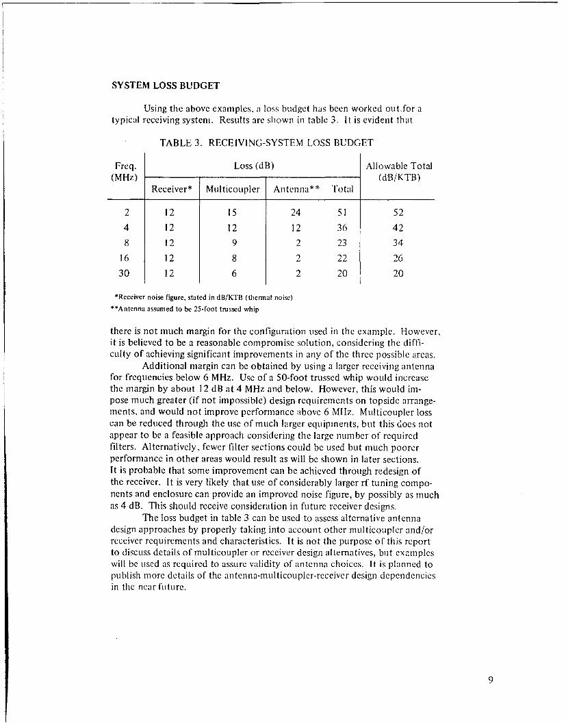
SYSTEM LOSS BUDGET
Using the above examples, a loss budget has been worked out.for atypical receiving system. Results are shown in table 3. It is evident that
TABLE 3. RECEIVING-SYSTEM LOSS BUDGET
Freq. Loss (dB) Allowable Total(MHz) (dB/KTB)
Receiver* Multicoupler Antenna** Total
2 12 15 24 51 52
4 12 12 12 36 42
8 12 9 2 23 34
16 12 8 2 22 26
30 12 6 2 20 20
*Receiver noise figure, stated in dB/KTB (thermal noise)
"**Antenna assumed to be 25-foot trussed whip
there is not much margin for the configuration used in the example. However,it is believed to be a reasonable compromise solution, considering the diffi-culty of achieving significant improvements in any of the three possible areas.
Additional margin can be obtained by using a larger receiving antennafor frequencies below 6 MHz. Use of a 50-foot trussed whip would increasethe margin by about 12 dB at 4 MHz and below. However, this would im-pose much greater (if not impossible) design requirements on topside arrange-ments, and would not improve performance above 6 MHz. Multicoupler losscan be reduced through the use of much larger equipments, but this does notappear to be a feasible approach considering the large number of requiredfilters. Alternatively, fewer filter sections could be used but much poorerperformance in other areas would result as will be shown in later sections.It is probable that some improvement can be achieved through redesign ofthe receiver. It is very likely that use of considerably larger rf tuning compo-nents and enclosure can provide an improved noise figure, by possibly as muchas 4 dB. This should receive consideration in future receiver designs.
The loss budget in table 3 can be used to assess alternative antennadesign approaches by properly taking into account other multicoupler and/orreceiver requirements and characteristics. It is not the purpose of this reportto discuss details of multicoupler or receiver design alternatives, but exampleswill be used as required to assure validity of antenna choices. It is planned topublish more details of the antenna-multicoupler-receiver design dependenciesin the near future.
9

RECEIVING ON TRANSMITTING ANTENNA
An alternative design approach is to use transmitting antennas forreceiving also. This can be accomplished by decoupling from the antennacoax and using the receiving multicouplers as in the above example (fig. 1).
DECOUPLINGNETWORK
IRECEIVE
MULTICOUPLER(AN/SRA-49)
IRECEIVER
Figure 1. Common transmit/receive antenna with decoupling at antenna bus.
There is a requirement that the decoupling network not appreciably affecttransmitting-antenna impedance. A separate study is underway at NELC todevelop a practical decoupling network and other related design details fora combination antenna receive-transmit system (CARTS). A report coveringthis work is planned for the near future. Discussions here will not includedetails of its design but will be limited to power budget and factors related to
compatibility when using the common antenna approach.A primary requirement for a decoupling network is that of assuring
sufficient total receiving-system sensitivity. Results of table 3 were used todetermine maximunm allowable decoupling from the antenna bus in order tojust achieve sensitivity goals. Losses in receiver and multicoupler were sub-tracted from illowable total loss in determining allowable decoupling. Re-stilts are as follows: 2 Mlz, 25 dBl 4 Mlz, 18 dB; 8 MHz, 13 dB: 16 MHz,0 d13: and 30 MHz, 2 dB. Results to date from the CARTS work indicatethat decoupling of 12 dB or more is probably required in order to avoid
10)

impedance changes in the transmitting antenna. This applies to the case forreceiving and transmitting in the same frequency band. In the case of receiv-ing outside the transmitting band, the primary requirement is that the .VSWRnot be appreciably changed within the transmitting band. From thesegeneral comments it appears that in the 2-6 MHz band it may be feasible touse the common-antenna approach. In the CARTS design, consideration isbeing given to using the 2-6 MHz transmitting antenna for 2-30 MHz recep-tion, and this probably can be accomplished by allowing a decrease in de-coupling above 6 MHz in a controlled manner. There may be a possibility ofusing a higher frequency antenna for receiving at lower frequencies with adecreased decoupling below its design band. However, it probably will notbe feasible to receive and transmit in the same band above about 6 MHz usingdecoupling at the antenna coax, because allowable decoupling is not greatenough.
Another approach for using a common transmit/receive antenna is tocouple the receiver to the line between transmitter and multicoupler by usinga transmit/receive switch. This is allowable only for simplex operation (trans-mit and receive alternately on the same frequency). There are a large numberof such circuit requirements at hf, particularly below 6 MHz. This is the partof the spectrum where the greatest crowding occurs and it typically presentsdesign problems. Therefore, consideration should be given to using thiscapability if probable compatibility can be shown. In this approach the lossbudget is considerably different, in that the receiving multicouplers may beoptional and direct coupling (through the T/R switch) is possible. Figure 2shows the options that are available.
When coupling at the transmitter, a large part of the off-frequencyrejection is achieved in the transmitting multicoupler, since it is tuned to thecommon transmit/receive frequency for transmitting. The transmitting multi-couplers have a typical rejection of about 28 dB at 21/-, percent spacing fromthe adjacent transmitting frequency and about 40 dB at 5 percent. This ismuch less than the rejection obtained in receiving multicouplers, particularlyat the lower frequencies. However, there are design requirements in the caseof transmitting multicouplers that preclude operation at frequency spacingsless than 5 percent. For this reason the receiver coupled to a transmittingantenna will always be spaced at least 5 percent from the nearest transmitterthat is on at the same time. More details of the required rejection will becovered in a later section of this report. In addition to this difference in re-jection, the transmitting multicouplers have a much lower insertion loss inthe operating passband. This is typically 2 dB instead of the 6 to 15 d1Bassociated with the receiving multicouplers as shown in table 2. Since thetransmitting antenna has a mismatch loss of only about 1 dB in its operatingband, it is clear that there is a large safety factor in the receiving loss budgetwhen only the transmitting multicoupler is used to protect the receiver.Table 4 shows the loss budget for option No. 3 discussed above. includingniargin for decoupling in case this is needed. Results show thla t both multi-con plers can be used in tandem up to ilear 30 NlIlz in case thiis is re(tiuiredto protcct the receiver. 1lowcvcr, as will be discw~scd I. tcr, thisiii% Tai henecessary or desirable in most cases. In case the rcckivi in maltice,, picr k
11

I TRANSMITTER I- I T/R , TRANSMIT OPTION 1SWITCH MULTICOUPLE R
RECEIVER
SWITCH MULTICOUPLER
NETWORK
WIT MULTICOUPLER
RECEIVEMULTICOUPLER
ORFILTER
EQUIVALENT
ISRECEIVER
Figure 2. Common transmit/receive antenna with connection at transmitter output.
not required. even more decoupling can be used since the receiving multi-coupler loss can be added to the margin. These results indicate that sensitivityshould not be a problem in using this approach, and protection of the receiveris the prime consideration.
12

"TABLE 4. LOSS BUDGET FOR RECEIVERCOUPLED AT TRANSMITTER OUTPUT
Transmitting ReceivingFreq. Allowable* Multi- Antenna Multicoupler/Filter Margin**(MHz) Total(dB) coupler(dB) (dB) (dB) (dB)
2 40 2 1 15 22
4 30 2 1 12 15
8 22 2 1 9 10
16 14 2 1 8 3
30 8 2 1 6 -1
*Allowable total from table 3 less 12 dB receiver loss
"**Margin for decoupling if both multicouplers are used in series
RECEIVER PROTECTION CONSIDERATIONS
There are several receiver characteristics that are closely related tostrong local transmitter interference. All of these are influenced by theamount of filtering placed ahead of the receiver and by the required spacingbetween receive frequencies and adjacent transmit frequencies. Four of theseare: (1) receiver cross-modulation caused by transferring modulation fromthe interfering signal to a signal on the receive frequency; (2) receiver over-load resulting from the receiver's being driven into its nonlinear region bythe interfering signal; (3) intermodulation caused by two interfering signalsmixing in receiver nonlinearities; and (4) receiver spurious responses. In eachcase sufficient filtering ahead of the receiver will eliminate the problem, pro-viding the attendant filter insertion loss can be tolerated. As shown in the pre-ceding sections (summarized in table 3), the AN/SRA-49 multicoupler providesa large degree of filtering with insertion loss that is acceptable but with noappreciable margin. It will be used as an example to determine the degreeof design difficulty associated with receiver protection. Of course the trans-mitting multicoupler will be used (w'th or without receiving multicoupler)for the case of coupling at the transmitter output.
Of the four receiver problem areas discussed above, unreported NELCtests have shown that cross-modulation is typically the most severe. Sincethis report is concerned with antenna design, discussion will be limited toexamination of cross-modulation under the assumption that the other receiverproblem areas will be resolved at the same time. This will be discussed inmore detail in a subsequent report under another problem. Measuremcntswere miade on receiver cross-nmodulation tinder a nother program at N[EL(' a 1d
13

results were used to assess filter requirements. A design goal of 21/2 percentspacing between transmit and receive frequencies was assumed. A decouplingfactor of 20 dB was assumed to account for the typical shipboard situationwithout taking into account the very complex decoupling actually existing.Assuming a radiated power level of I kW, the open-circuit voltage appearingon a good receiving antenna is expected to be 45 volts, which is 33 dB/l volt.The multicoupler rejection lowers this voltage by a large amount and expectedvoltage at the receiver terminals is shown in table 5. Figure 3 is a typical re-presentation of receiver cross-modulation and multicoupler rejection charac-teristics. The crossover points represent allowable minimum transmit/receivefrequency spacings for 1-kW radiated power and 20-dB decoupling. Also
TABLE5. RECEIVER (R-1051D) CROSS-MODULATIONPARAMETERS, SEPARATE RECEIVING ANTENNA
Allowable AllowableOpen-Ckt. SRA-49 Receiver Volt. at Recv. Frequency
Freq. Ant. Volt. Rejection Voltage (dB/l V at Deficiency Spacing(MHz) (dB/! V) (dB at 21/2%) (dB/l V) 21/2%) (dB) (%)
2 33 56 -23 -27 4 2.7
8 33 43 -10 -28 18 3.3
24 33 32 1 -29 30 4.1
shown are allowable levels at the receiver and allowable transmit/receivefrequency spacing if other than 212 percent. It is evident that the rejection ismarginal at 2 MHz and very inadequate at the higher frequencies. In theabsence of improved design it is necessary to increase the spacing from adja-cent transmitter frequencies. The SRA-49 has four tuned circuits and therejection increases rapidly with increased spacing. As a result the requiredspacing does not increase in proportion to the deficiency shown and the in-creased spacing may be an acceptable solution. It is apparent that a majorimprovement in decoupling would be required to meet design goals at 8 MHzand above if the only change made were that of decoupling. It may be possibleto improve receiver characteristics but this has not been determined. Noappreciable improvement in multicoupler rejection appears feasible since in-sertion loss is already approaching design limits. As discussed earlier in thisreport. insertion loss and rejection are interdependent.
The same consideration must be used in assessing feasibility of thecommon receive/transmit antenna approach. For the case of decoupling fromthe antenna bus (fig. I) it was determined that allowable decoupling is 25 dBmt 2 MliI. 18 dB at 4 Mlhz. and 13 dB at 8 MHz. For 2-6 MHz transmitteroperation, then, the allowable (decoupling will vary between 25 and about 15d1B. This is reasonably close to the nominal 20 dB used in the example forsepiralte receiving aniten nas, so this alpproach appears to be acceptable if anincrcase is ipacl ucan be tolera l (to about 3.3. percent) at 6 M0lz. It iscvidc.iit hlint opcration on higher-t reqivuvcy transmitting antennas would

|w
I-*
1000_
-J0>
zwI-z
-- 100
0
ZDz
10
0.95 0.96 0.97 0.98 0.99 1 1.01 1.02 1.03 1.04 1.05
f /f 0
* ALLOWABLE LINDESIRE DSIGNAL LEVEL FOR R-1051 (DESIRED SIGNAL,10pIV, 30% MODULATED AT 1000 Hz IN SERIES WITH 50-OHM ANTENNA)
SUNDESIRED SIGNAL 45 VOLTS IN SERIES WITH 50-OHM ANTENNA PLUSCOMPUTED AN/SRA-49 FILTER REJECTION (REFERRED TO RECEIVERINPUT TERMINALS)
Figure 3. Receiver-trainsmitter spacing requirements based on cross-modulationIlimitations for AN/SRA-49, R 1051 receiving system. Receiver tuned to 8 MHz.AN/SRA-49 rejection based on rejection at a tuned frequency of 7 MHz.
15

require even greater frequency spacings than for the separate receiving-anten-na case because of the small allowable decoupling. However, this was foundnot to be acceptable because of loss-budget problems anyway.
Consideration of the case for coupling in at the transmitter terminalsleads to different conclusions, principally because the simplex operation as-sumed limits spacing to 5 percent or greater. Under this situation the trans-mit-transmit spacing sets the minimum, which is typically 5 percent. In thiscase the first rejection is derived from the transmitting multicoupler and, at5 percent spacing, is about 40 dB over the 2-30 MHz band. Theequivalentopen-circuit voltage from the interfering transmitter radiating 1 kWis 4.5volts at the T/R switch point. Table 6 lists pertinent characteristics for cross-modulation when coupling at this point. Results indicate a major deficiency
TABLE 6. RECEIVER (R-11051 D) CROSS-MODULATIONPARAMETERS, COUPLED AT TRANSMITTER TERMINALS
SRA-56* Receiver Allowable Allowable Margin withFreq. Rejection Voltage Rec. Volt. Deficiency Decoupling Decoupling(MHz) (dB at 5%) (dB/l V) (dB/l V at 5%) (dB) (dB) (dB)
2 40 13 -6 19 38 19
8 40 13 -5 18 20 2
24 40 13 -4 17 9 -8
*SRA-56/57/58 series transmitting multicoupler
if no coupling is used and if no receiving multicoupler/filter is used. How-ever, use of a simple deccupling network without receiving multicoupler/fil-ter in series will provide adequate protection uIp to 8 MHz. (The use of theterm multicoupler/filter indicates that a single tunable filter serves each re-ceiver and this is assumed to be equivalent to one port of the SRA-49 receiv-ilig multicoupler.) Above 8 MHz the allowable decoupling gradually becomesinsufficient and acceptable performance must be obtained by increasing spac-ing beyond 5 percent or by using the receiving multicoupler/filter in series.As shown in a preceding section this is acceptable from a loss-budget stand-point. With only the allowable decoupling used, the required spacing wouldincrease from 5 percent at 8 MHz to 6 percent at 24 MHz. From these re-stilts it appears that, by accepting a small spacing penalty, simplex operationcan be used over most, if not all, of the 2-30 MHz range without the use ofadditional filtering. If transmit-transmit frequency spacings of less than 5percent were to be used, additional receive filtering would be required. Thisconclusion entails several other transmitting-system considerations and is notrecommended unless detailed analyses of special cases indicate the resultingperformance to be acceptable.
(0

MINIATURE RECEIVING ANTENNAS
Another approach to the receiving-antenna design problem is that oftunable miniature antennas. There are two such miniature antennas pre-sently available for use at hf: the AN/SRA-43 for 2-8 MHz operation, de-veloped at NELC, and the AN/SRA-51 for 2-16 MHz, developed by DECO-Westinghouse under Navy contract. Both antennas use short whips, approxi-mately 5 feet long, and are remotely tuned. Each serves only one receiverbecause of the necessity of tuning to achieve sufficient sensitivity. Analysisof the performance of these antennas is quite complex because their efficien-cy is greatly influenced by their locations on ship structures. It is not thepurpose of this report to assess their effectiveness in any detail, but thisgeneral information regarding them is included for completeness.
DIVERSITY-RECEPTION CONSIDERATIONS
A number of investigations have been conducted under other NELCprograms5' 6 to determine the merit of diversity reception at hf. These indi-cate that use of antenna diversity in addition to tone diversity (twinning) inthe multichannel broadcast or ship/shore system can provide a reduction of3/1 to 5/1 in error rate. Tentative results indicate that either polarizationdiversity or space diversity can provide these gains even within the dimensionsavailable aboard ship. Since the available equipmexts ashore and aboard shiphave this combining capability, it is expected that future ship-antenna designswill be required to address this problem. The alternative receiving-systemapproaches discussed in this report make it more likely that some diversitycapability is achievable. For instance, a stern-mounted, twin-whip antennacould be used in conjunction with a 2-6 MHz transmitting antenna (decoupledfor receiving) to provide a space diversity capability. There is an additionaldiversity action resulting from having noncorrelated azimuthal patternswhich should further improve receiving capability. These possibilities indi-cate the need for determining specific receiving-antenna design feasibility, toallow choices when developing antenna arrangement plans.
CONCLUSIONS
1. Several alternative receiving-antenna approaches provide capabilityof meeting system-sensitivity requirements. However, when required receiverprotection against strong local signa!s is taken into account, tentative designgoals can be met only partially for some options.
17

2. Use of a 25-foot trussed whip with an AN/SRA-49 receiving multi-coupler and an R- 105 ID receiver will just meet sensitivity requirements at 2MHz and at 30 MHz with some margin at midband.
3. With an assumed 20-dB decoupling between transmitting and receiv-ing antennas and with equipment listed in (2) above, the goal of 21/2 percentspacing between receive and trmnsmit frequencies cannot be met. Requiredspacing is 2.7, 3.3, and 4.1 percent at 2, 8, and 24 MHz, respectively.
4. It is not probable that the design goal of 27/2-percent spacing can bemet with broadband receiving antennas by space isolation. However, theanalytical model developed in this report will allow assessment of specificantenna designs for such determination.
5. Use of a 2-6 MHz transmitting antenna for receiving appears to befeasible through decoupling at the antenna bus to an AN/SRA-49 receivingmulticoupler. Sensitivity requirements can be met over the 2-6 MHz band,with frequency-spacing requirements'slightly worse than stated in (3) above.
6. It may be possible to also use the 2-6 MHz antenna for receiving be-tween 6 and 30 MHz providing the antenna has acceptable directivity andimpedance characteristics. Separate investigations are being conducted tofurther determine such feasibility.
7. Decoupling requirements (to achieve acceptable sensitivity) maypreclude using the above approach for transmitting antennas above 6 MHz.
8. Use of transmitting antennas for receiving i,- simplex operation(transmit and receive alternately on same frequency) can be accommodatedthrough coupling the receiver at the transmitter output with a transmit/receive(T/R) switch. In this case, spacing to the nearest other transmit frequency isrestricted to 5 percent or more because of transmitting-system requirements.
9. Several coupling options are available for the above simplex case andsensitivity goals can be met with any of them. Other considerations (com-plexity and frequency spacing) indicate that the probable best choice is thatof controlled decoupling without a receive multicoupler/filter in tandem.
10. The options available for receiving-system design are important inproviding more than one receiving antenna for use in antenna diversity schemes.Antenna diversity can probably provide at least a 3/1 reduction in error rate.
RECOMMENDATIONS
1. Use the results developed here as guidance in designing shipboard,receiving antennas and in evaluating proposed designs.
2. Use the results developed here to assess possible improvements inmulticouplers and receivers to eliminate deficiencies shown to be of impor-tance.
3. Continue design-feasibility studies at NELC to determine the potentialof the combination antenna receive-transmit system (CARTS).
4. Conduct design studies of other common transmit/receive antennaapproaches discussed in this report, to determine their technical and opera-tional advantages for simplex operation.
5. Emphasize development and use of multiple receiving-antenna cap-abilities for antenna diversity applications.
19
REFERENCES
I. International Radio Consultative Committee. 10th Plenary Assembly,Geneva, 1963 Report 3 22, World Distribution and Characteris'ticso• A tmospheric Radio Noise. International Telecommunication Union,1964.
2. National Bureau of Standards Technical Note 18-13, Quarterly RadioNoise Data -- December, January, February 1961-1962, 22 May 1962.
3. Chu Associates, Ambient Shipboard Noise Measurements AboardUSS RICHARD S. EDWARDS (DD-950) and USS HENRY B. WILSON(DDG-7). 21 October 1963.
4. ChU Associates, Ambient Shipboard Noise Measurements AboardLISS BUCK (DD- 76 1) and USS YORKTOWN (C VS-J O), 25 August1964.
5. Naval Electronics Laboratory Center Report 1620, Error Rate (,f High-Frequency Multi-Channel Fleet Broadcast System, by J. L. Heritage,27 March 1969.
6. Naval Electronics Laboratory Center Report 1634, Error Rate Observedon IlFMultichannel Fleet Broadcast System, by G. B. Johnson andG. P. Francis, 28 July 1969.
UNCLASSIFIEDSecurityt• C'lassification
DOCUMENT CONTROL DATA R & DSrt'c.rety ctabsItieIIOn of litle, hd, o, Ib• -ot a-d -deoira ,I otio t r.l,,I h, -ci-red7 I, e l .n,, .fl r. , 'I., ,I-d
ONI GNA TING AC I IVI T Y [Corporate a410hor,) 2. FI'ORT SI C . , 1L , 11( 1 10'
Naval Electronics Laboratory Center UNCLASSIFIED
San Diego, California 92152
3 REPORT TITLE
SHIPBOARD HF RECEIVING ANTENNA SYSTEM: DESIGN CRITERIA
SDESC RIP TIVE NOTES (Type t repo-t and inlsiee dates)
Research and Development, October 1969 - April 1970I AU THORIRI (Furst name, middte initial. tent name)
W. E. Gustafson and W. M. Chase
4 REPORT DATE 7S. TOTAL NO. OF PAGES 75. NO OF REFS
2 June 1970 22 6*0. CONTRACT OR GRANT NO. 9S. ORIGINATOR'S REPORT NuMPER(SI
b. PROJECT .O. SF 14.222.004, Task 13950 1712(NELC B 164)
C. 9b. OTHER REPORT NO(SI (Any ether numbers that may be asstgnedthia report)
d.
t0 DISTRI BUTION STATEMENT
This document is subject to special export controls and each transmittal to foreign governments orforeign nationals may be made only with prior approval of Naval Electronics Laboratory Center,San Diego, California 92152.
I. SUPPLEMENTARY NOTES 12. SPONSORING MILITARY ACTIVITY
Naval Ship Systems Command
13 ABSTRACT
A study of critical factors related to hf receiving-system design, such as antenna coupling andefficiency, multicoupler performance, receiver overload effects, transmitter noise, and atmosphericnoise.
DD 1ORM 1473 (PACE I) UNCLASSIFIED0' 0 (01- . 07- O lt(I., -'Iv ClaI.fj, alTOn
6

Security Classilication
K LINK A LINK 6 LINK C
ROLE WT ROLE WT ROLE WT
Design standards
High frequency antennas
Ship antennas
DD NO• 1473 (R&K(PAGF 2) Security Classification