new flute analysis - pudn.comread.pudn.com/downloads76/doc/comm/285290/new flute analysis.… ·...
TRANSCRIPT

Page 1 of 48
FLUTE Analysis
Page 2 of 48
Content 1 Introduction...............................................................................................................................3 2 Architecture...............................................................................................................................3
2.1 Layered Coding Transport.........................................................................................5 2.1.1 Introduction.......................................................................................................5 2.1.2 Rationale ...........................................................................................................5 2.1.3 Functionality .....................................................................................................6 2.1.4 Applicability......................................................................................................8 2.1.5 Packet Header Fields.........................................................................................9 2.1.6 Requirements from Other Building Blocks.....................................................15
2.2 File Delivery Table..................................................................................................16 2.2.1 Introduction.....................................................................................................16 2.2.2 File Delivery Table..........................................................................................16
2.3 Forward Error Correction........................................................................................23 2.3.1 Introduction.....................................................................................................23 2.3.2 FEC Information .............................................................................................24 2.3.3 FEC Codes ......................................................................................................26 2.3.4 Packet Header Fields.......................................................................................29 2.3.5 Delivering FEC OTI in FLUTE ......................................................................33
2.4 Multiple-rate Congestion Control ...........................................................................36 2.4.1 Introduction.....................................................................................................36 2.4.2 Formulation on Two Kinds of Congestion Control .........................................37 2.4.3 Multiple-rate Congestion Control for FLUTE ................................................37 2.4.4 Problem ...........................................................................................................38
2.5 Packet Authentication..............................................................................................38 2.5.1 Security Considerations ..................................................................................38 2.5.2 Motivations for Security Considerations.........................................................39 2.5.3 Relevant Solutions ..........................................................................................40
3 FLUTE Packet ........................................................................................................................41 3.1 Constructing FLUTE packets..................................................................................41 3.2 Overview of packet format......................................................................................42
4 Session Description.................................................................................................................43 4.1 File Delivery Session of FLUTE.............................................................................43 4.2 Describing file delivery sessions.............................................................................44
5 Sender & Receiver Operation .................................................................................................45 5.1 Sender Operation.....................................................................................................45 5.2 Receiver Operation..................................................................................................45
6 References...............................................................................................................................46

Page 3 of 48
1. Introduction
The File Delivery over Unidirectional Transport protocol (FLUTE) is a unidirectional reliable file delivery protocol.
FLUTE is built on top of Asynchronous Layered Coding protocol, or ALC protocol instance, which defines the transport of arbitrary binary objects. However, only ALC is not enough for reliable transport of files and the requirement of massive scalability. The receivers need to know what these objects represent. Therefore, FLUTE defines a mechanism for signaling and mapping the properties of files to concepts of ALC in a way that allows receivers to assign those parameters for received object.
FLUTE is designed mainly for the massive scalability. In this document, massive scalability means the number of concurrent receivers for an object is potentially in the millions, the aggregate size of objects to be delivered in a session ranges from hundreds of kilobytes to hundreds of gigabytes, each receiver can initiate reception of an object asynchronously, the reception rate of each receiver in the session is the maximum fair bandwidth available between that receiver and the sender, and all of this can be supported using a single sender.
FLUTE is applicable to the delivery of large and small files to many hosts, using delivery sessions of several seconds or more. For instance, FLUTE could be used for the delivery of large software updates to many hosts simultaneously. It could also be used for continuous, but segmented data such as time-lined text for subtitling - potentially leveraging its layering inheritance from ALC and LCT to scale the richness of the session to the congestion status of the network.
This document is structured as follows. Section 2 begins by describing the overall architecture of FLUTE. Following that it introduces every components of FLUTE in details. Section 3 first illustrates what a FLUTE packet is by means of a Figure, and then defines the format of packet, by which the file is carried. Section 4 concentrates on two very important conceptions in FLUTE – Session & Session Description. In this section, the specific content of session description is defined. The following section, section 5, describes the operations of sender and receiver step by step in a session.
2. Architecture
FLUTE is built on top of ALC. Besides ALC, the File Delivery Table is a new component in FLUTE. The File Delivery Table (FDT) provides a means to describe various attributes associated with files that are to be delivered within the file delivery session.
FLUTE uses the LCT building block [17] to provide the definition of packet format and in-band session management functionality. Meanwhile, FLUTE uses a multiple rate congestion control building block that is compliant with RFC 2357 [18] to provide congestion control that is feedback free. Receivers adjust their reception rates individually by joining and leaving channels associated with the session.
FLUTE uses the FEC building block [1] to provide reliability. The sender generates encoding

Page 4 of 48
symbols based on the object to be delivered using FEC codes and sends them in packets to channels associated with the session. Receivers simply wait for enough packets to arrive in order to reliably reconstruct the object. Thus, there is no request for retransmission of individual packets from receivers that miss packets in order to assure reliable reception of an object, and the packets and their rate of transmission out of the sender can be independent of the number and the individual reception experiences of the receivers.
For security considerations, FLUTE needs packets authentication to protect against the Denial-of-Service attacks. What’s more, content encoding could be added if necessary. Because of applicability problem, we don’t deal with the content encoding in this document.
Besides these building blocks mentioned above, session description is also a very important part for the whole protocol. But because of the core role it plays in FLUTE, we will discuss it specifically later in section 4.
The overall architecture of FLUTE can be illustrated as follows, in Figure 1.
Figure 1- Architecture of FLUTE
Page 5 of 48
2.1. Layered Coding Transport
2.1.1. Introduction
Layered Coding Transport (LCT) provides transport level support for reliable content delivery (e.g. FLUTE) and stream delivery protocols. It is specifically designed to support protocols using IP multicast, but also provides support to protocols that use unicast.
LCT could be considered as a general framework, which is compatible with congestion control that provides multiple rate delivery to receivers and is also compatible with coding techniques that provide reliable delivery of content, or is compatible with packet authentication schemes that provide secure transport guarantee. In other words, an integrated protocol instance might use LCT building block associated with other necessary functionality building blocks (e.g. Congestion Control building block, FEC building block, Packet Authentication building block etc.) to perform its natural action.
2.1.2. Rationale
2.1.2.1. Supports for Congestion Control
An LCT session comprises multiple channels originating at a single sender that are used for some periods of time to carry packets pertaining to the transmission of one or more objects that can be of interest to receivers. The logic behind defining a session as originating from a single sender is that this is the right granularity to regulate packet traffic via congestion control.
One rationale for using multiple channels within the same session is that there are massively scalable congestion control protocols that use multiple channels per session. These congestion control protocols are considered to be layered because a receiver joins and leaves channels in a layered order during its participation in the session. The use of layered channels is also useful for streaming applications. There are coding techniques that provide massively scalable reliability and asynchronous delivery which are compatible with both layered congestion control and with LCT. When all are combined the result is a massively scalable reliable asynchronous content delivery protocol that is network friendly. LCT also provides functionality that can be used for other applications as well, e.g., layered streaming applications. It’s noted that LCT avoids providing functionality that is not massively scalable. For example, LCT does not provide any mechanisms for sending information from receivers to senders, although this does not rule out protocols that both use LCT and do require sending information from receivers to senders. LCT includes general support for congestion control that must be used. It does not, however, specify which congestion control should be used. The rationale for this is that congestion control must be provided by any protocol that is network friendly, and yet the different applications that can use LCT will not have the same requirements for congestion control. For example, a content
Page 6 of 48
delivery protocol may strive to use all available bandwidth between receivers and the sender. It must, therefore, drastically back off its rate when there is competing traffic. On the other hand, a streaming delivery protocol may strive to maintain a constant rate instead of trying to use all available bandwidth, and it may not back off its rate as fast when there is competing traffic.
2.1.2.2. Supports for General Functionality
Beyond support for congestion control, LCT provides a number of fields and supports functionality commonly required by many protocols. For example, LCT provides a Transmission Session ID that can be used to identify which session each received packet belongs to. This is important because a receiver may be joined to many sessions concurrently, and thus it is very useful to be able to demultiplex packets as they arrive according to which session they belong to. As another example, LCT provides optional support for identifying which object each packet is carrying information about. Therefore, LCT provides many of the commonly used fields and support for functionality required by many protocols.
2.1.3. Functionality
2.1.3.1. Channel
An LCT session consists of a set of logically grouped LCT channels associated with a single sender carrying packets with LCT headers for one or more objects. An LCT channel is defined by the combination of a sender and an address associated with the channel by the sender. A receiver joins a channel to start receiving the data packets sent to the channel by the sender, and a receiver leaves a channel to stop receiving data packets from the channel.
2.1.3.2. Scalability
LCT is meant to be combined with other building blocks so that the resulting overall protocol is massively scalable. Scalability refers to the behavior of the protocol in relation to the number of receivers and network paths, their heterogeneity, and the ability to accommodate dynamically variable sets of receivers. Scalability limitations can come from memory or processing requirements, or from the amount of feedback control and redundant data packet traffic (generally data retransmissions) generated by the protocol. In turn, such limitations may be a consequence of the features that a complete reliable content delivery or stream delivery protocol is expected to provide.
2.1.3.3. Functionality Fields in LCT Header
The LCT header provides a number of fields that are useful for conveying in-band session information to receivers. One of the required fields is the Transmission Session ID (TSI), which allows the receiver of a session to uniquely identify received packets as part of the session.

Page 7 of 48
Another required field is the Congestion Control Information (CCI), which allows the receiver to perform the required congestion control on the packets received within the session. Other LCT fields provide optional but often very useful additional information for the session. For example, the Transport Object Identifier (TOI) identifies which object the packet contains data for. As other examples, the Sender Current Time (SCT) conveys the time when the packet was sent from the sender to the receiver, the Expected Residual Time (ERT) conveys the amount of time the session will be continued for, flags for indicating the close of the session and the close of sending packets for an object, and header extensions for fields that for example can be used for packet authentication.
2.1.3.4. Congestion Control
LCT provides support for congestion control. Congestion control must be used that conforms to RFC 2357 [18] between receivers and the sender for each LCT session. Congestion control refers to the ability to adapt throughput to the available bandwidth on the path from the sender to a receiver, and to share bandwidth fairly with competing flows such as TCP. Thus, the total flow of packets flowing to each receiver participating in an LCT session must not compete unfairly with existing flow adaptive protocols such as TCP. A multiple rate or a single rate congestion control protocol can be used with LCT. Please refer to congestion control section (Sec. 2.4) for more details.
2.1.3.5. Layered Coding
Layered coding refers to the ability to produce a coded stream of packets that can be partitioned into an ordered set of layers. The coding is meant to provide some form of reliability, and the layering is meant to allow the receiver experience (in terms of quality of playout, or overall transfer speed) to vary in a predictable way depending on how many consecutive layers of packets the receiver is receiving. The concept of layered coding was first introduced with reference to audio and video streams. For example, the information associated with a TV broadcast could be partitioned into three layers, corresponding to black and white, color, and HDTV quality. Receivers can experience different quality without the need for the sender to replicate information in the different layers. The concept of layered coding can be naturally extended to reliable content delivery protocols when Forward Error Correction (FEC) techniques are used for coding the data stream. Descriptions of this can be found in [19], [5], [20], [21] and [22]. By using FEC, the data stream is transformed in such a way that reconstruction of a data object does not depend on the reception of specific data packets, but only on the number of different packets received. As a result, by increasing the number of layers a receiver is receiving from, the receiver can reduce the transfer time accordingly. Using FEC to provide reliability can increase scalability dramatically in comparison to other methods for providing reliability. More details on the use of FEC for reliable content delivery can be found in [1].

Page 8 of 48
2.1.3.6. Reliability with Scalability Considerations
Reliable protocols aim at giving guarantees on the reliable delivery of data from the sender to the intended recipients. Guarantees vary from simple packet data integrity to reliable delivery of a precise copy of an object to all intended recipients. Several reliable content delivery protocols have been built on top of IP multicast using methods other than FEC, but scalability was not the primary design goal for many of them. Two of the key difficulties in scaling reliable content delivery using IP multicast are dealing with the amount of data that flows from receivers back to the sender, and the associated response (generally data retransmissions) from the sender. Protocols that avoid any such feedback, and minimize the amount of retransmissions, can be massively scalable. LCT can be used in conjunction with FEC codes or a layered codec to achieve reliability with little or no feedback.
Protocol instantiations may be built by combining the LCT framework with other components. A complete protocol instantiation that uses LCT must include a congestion control protocol that is compatible with LCT and that conforms to RFC 2357 [18]. A complete protocol instantiation that uses LCT may include a scalable reliability protocol that is compatible with LCT, it may include a session control protocol that is compatible with LCT, and it may also include other protocols such as security protocols.
2.1.4. Applicability
LCT is most applicable for delivery of objects or streams in a session of substantial length, i.e., objects or streams that range in aggregate length from hundreds of kilobytes to many gigabytes, and where the duration of the session is on the order of tens of seconds or more. Before joining a session, the receivers must obtain enough of the session description to start the session. This must include the relevant session parameters needed by a receiver to participate in the session, including all information relevant to congestion control. The session description is determined by the sender, and is typically communicated to the receivers out-of-band. In some cases, as described later, parts of the session description that are not required to initiate a session may be included in the LCT header or communicated to a receiver out-of-band after the receiver has joined the session.
2.1.4.1. Environmental Requirements and Considerations
LCT is intended for congestion controlled delivery of objects and streams (both reliable content delivery and streaming of multimedia information). LCT can be used with both multicast and unicast delivery. LCT requires connectivity between a sender and receivers but does not require connectivity from receivers to a sender. LCT inherently works with all types of networks, including LANs, WANs, Intranets, the Internet, asymmetric networks, wireless networks, and satellite networks. Thus, the inherent raw scalability of LCT is unlimited. However, when other specific applications are built on top of LCT, then these applications by their very nature may limit scalability. For example, if an application requires receivers to retrieve out of band information in order to join a session or an application allows receivers to send requests back to the sender to

Page 9 of 48
report reception statistics, then the scalability of the application is limited by the ability to send, receive, and process this additional data.
2.1.4.2. Delivery service models
LCT can support several different delivery service models. Two familiar models are briefly described here.
2.1.4.2.1. Push Service Model
One way a push service model can be used for reliable content delivery is to deliver a series of objects. For example, a receiver could join the session and dynamically adapt the number of LCT channels the receiver is joined to until enough packets have been received to reconstruct an object. After reconstructing the object the receiver may stay in the session and wait for the transmission of the next object. The push model is particularly attractive in satellite networks and wireless networks. In these cases, a session may consist of one fixed rate LCT channel.
2.1.4.2.2. On-demand Content Delivery Model
For an on-demand content delivery service model, senders typically transmit for some given time periods selected to be long enough to allow all the intended receivers to join the session and recover the object. In this case the receivers join the session, and dynamically adapt the number of LCT channels they subscribe to according to the available bandwidth. Receivers then drop from the session when they have received enough packets to recover the object.
2.1.4.2.3. Other Service Models
There are many other delivery service models that LCT can be used for that are not covered above, such as a live streaming or an on-demand archival content streaming service model.
2.1.5. Packet Header Fields
Packets sent to an LCT session must include an “LCT header”. The LCT header format described below is the default format, and this is the format that is recommended for use by protocol instantiations to ensure a uniform format across different protocol instantiations. Moreover, other LCT header formats may be used by some specific protocol instantiations. Other building blocks included in a protocol instance may describe some of the same fields as described for the LCT header. It is better that protocol instantiations using multiple building blocks include shared fields at most once in each packet.
Page 10 of 48
2.1.5.1. Default LCT header format
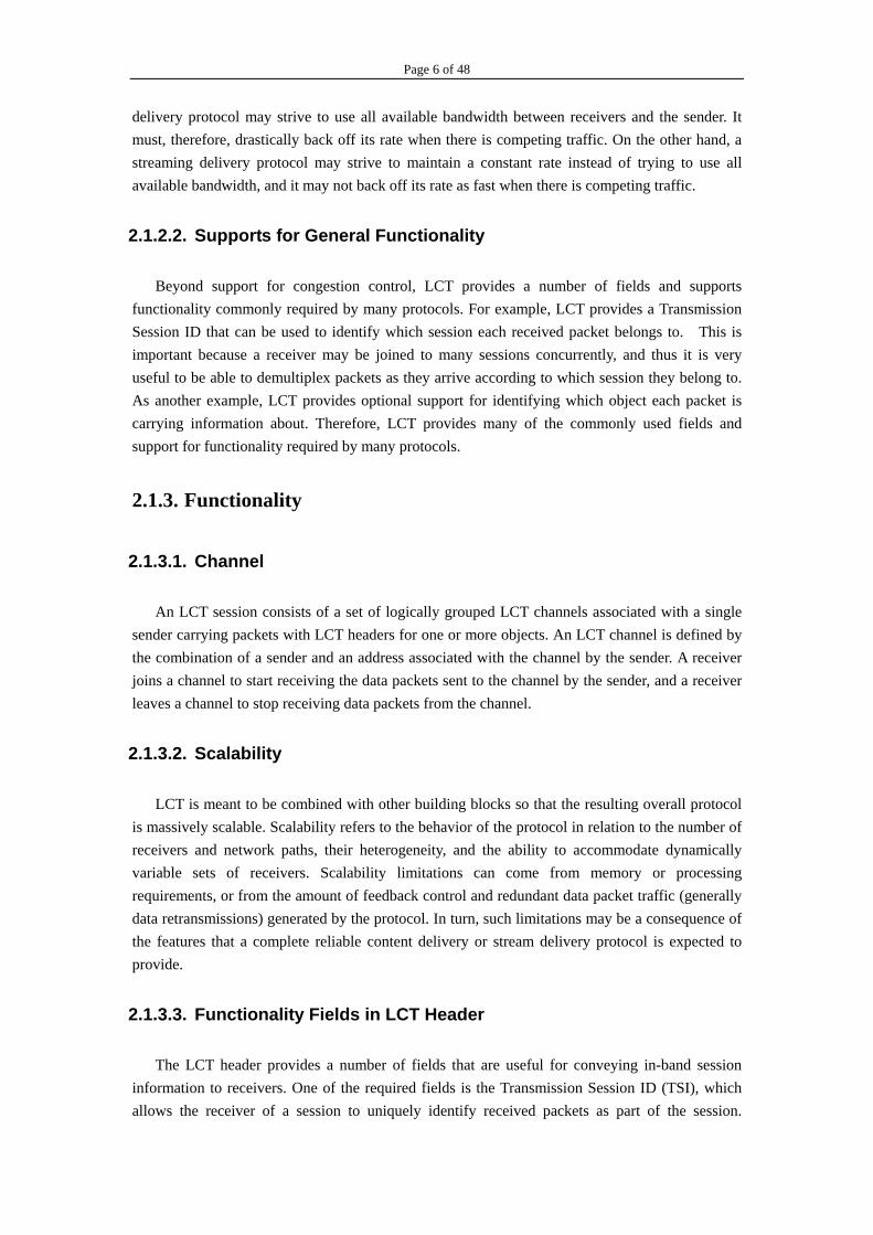
The default LCT header is of variable size, which is specified by a length field in the third byte of the header. In the LCT header, all integer fields are carried in "big-endian" or "network order" format, that is, most significant byte (octet) first. Bits designated as "padding" or "reserved" (r) must by set to 0 by senders and ignored by receivers. Unless otherwise noted, numeric constants in this specification are in decimal (base 10). The format of the default LCT header is depicted in Figure 2.
Figure 2- Default LCT header format
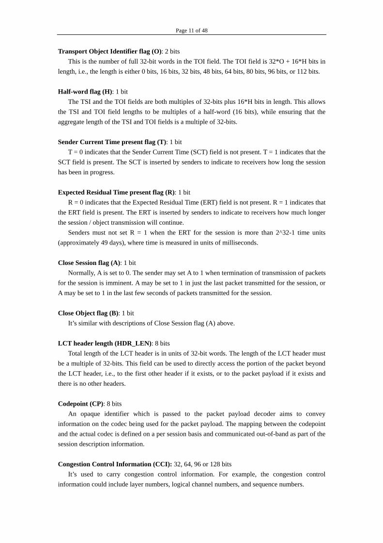
LCT version number (V): 4 bits
Indicate the LCT version number. The LCT version number for this specification is 1. Congestion control flag (C): 2 bits C=0 indicates the 32-bit CCI field format is to be used. C=1 indicates the 64-bit CCI field format is to be used. C=2 indicates the 96-bit CCI field format is to be used. C=3 indicates the 128-bit CCI field format is to be used. Reserved (r): 2 bits
It’s reserved for future use. A sender must set these bits to zero and a receiver must ignore these bits.
Transport Session Identifier flag (S): 1 bit
This is the number of full 32-bit words in the TSI field. The TSI field is 32*S + 16*H bits in length, i.e. the length is either 0 bits, 16 bits, 32 bits, or 48 bits.
Page 11 of 48
Transport Object Identifier flag (O): 2 bits This is the number of full 32-bit words in the TOI field. The TOI field is 32*O + 16*H bits in
length, i.e., the length is either 0 bits, 16 bits, 32 bits, 48 bits, 64 bits, 80 bits, 96 bits, or 112 bits.
Half-word flag (H): 1 bit The TSI and the TOI fields are both multiples of 32-bits plus 16*H bits in length. This allows
the TSI and TOI field lengths to be multiples of a half-word (16 bits), while ensuring that the aggregate length of the TSI and TOI fields is a multiple of 32-bits. Sender Current Time present flag (T): 1 bit
T = 0 indicates that the Sender Current Time (SCT) field is not present. T = 1 indicates that the SCT field is present. The SCT is inserted by senders to indicate to receivers how long the session has been in progress. Expected Residual Time present flag (R): 1 bit
R = 0 indicates that the Expected Residual Time (ERT) field is not present. R = 1 indicates that the ERT field is present. The ERT is inserted by senders to indicate to receivers how much longer the session / object transmission will continue.
Senders must not set R = 1 when the ERT for the session is more than 2^32-1 time units (approximately 49 days), where time is measured in units of milliseconds. Close Session flag (A): 1 bit
Normally, A is set to 0. The sender may set A to 1 when termination of transmission of packets for the session is imminent. A may be set to 1 in just the last packet transmitted for the session, or A may be set to 1 in the last few seconds of packets transmitted for the session. Close Object flag (B): 1 bit It’s similar with descriptions of Close Session flag (A) above. LCT header length (HDR_LEN): 8 bits
Total length of the LCT header is in units of 32-bit words. The length of the LCT header must be a multiple of 32-bits. This field can be used to directly access the portion of the packet beyond the LCT header, i.e., to the first other header if it exists, or to the packet payload if it exists and there is no other headers. Codepoint (CP): 8 bits
An opaque identifier which is passed to the packet payload decoder aims to convey information on the codec being used for the packet payload. The mapping between the codepoint and the actual codec is defined on a per session basis and communicated out-of-band as part of the session description information. Congestion Control Information (CCI): 32, 64, 96 or 128 bits
It’s used to carry congestion control information. For example, the congestion control information could include layer numbers, logical channel numbers, and sequence numbers.

Page 12 of 48
This field must be 32 bits if C=0. This field must be 64 bits if C=1. This field must be 96 bits if C=2. This field must be 128 bits if C=3. Transport Session Identifier (TSI): 0, 16, 32 or 48 bits The TSI uniquely identifies a session among all sessions from a particular sender. The TSI is scoped by the IP address of the sender, and thus the IP address of the sender and the TSI together uniquely identify the session. The length of the TSI field is 32*S + 16*H bits. Transport Object Identifier (TOI): 0, 16, 32, 48, 64, 80, 96 or 112 bits. This field indicates which object within the session this packet pertains to. The length of the TOI field is 32*O + 16*H bits. Sender Current Time (SCT): 0 or 32 bits
This field represents the current clock at the sender and at the time this packet was transmitted, measured in units of 1ms and computed modulo 2^32 units from the start of the session. This field must not be present if T=0 and must be present if T=1. Expected Residual Time (ERT): 0 or 32 bits
This field represents the sender expected residual transmission time for the current session or for the transmission of the current object, measured in units of 1ms. If the packet containing the ERT field also contains the TOI field, then ERT refers to the object corresponding to the TOI field, otherwise it refers to the session. This field must not be present if R=0 and must be present if R=1.
2.1.5.2. Header-Extension Fields
2.1.5.2.1. General LCT Header Extension
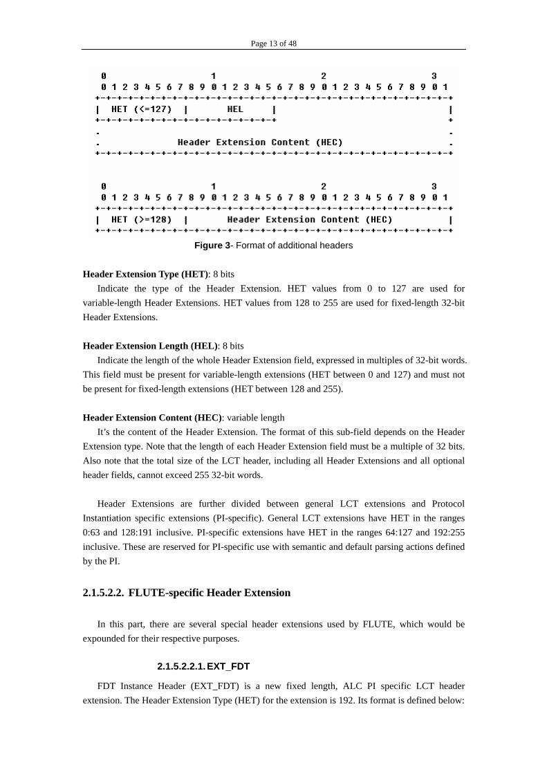
Header Extensions are used in LCT to accommodate optional header fields that are not always used or have variable size. The presence of Header Extensions can be inferred by the LCT header length (HDR_LEN): if HDR_LEN is larger than the length of the standard header then the remaining header space is taken by Header Extension fields. FLUTE protocol properly includes several Header Extension fields for its specific uses. There are two formats for Header Extension fields, as depicted below. The first format is used for variable-length extensions, with Header Extension Type (HET) values between 0 and 127. The second format is used for fixed length (one 32-bit word) extensions, using HET values from 127 to 255. The explanation of each sub-field is the following:
Page 13 of 48
Figure 3- Format of additional headers
Header Extension Type (HET): 8 bits
Indicate the type of the Header Extension. HET values from 0 to 127 are used for variable-length Header Extensions. HET values from 128 to 255 are used for fixed-length 32-bit Header Extensions. Header Extension Length (HEL): 8 bits
Indicate the length of the whole Header Extension field, expressed in multiples of 32-bit words. This field must be present for variable-length extensions (HET between 0 and 127) and must not be present for fixed-length extensions (HET between 128 and 255). Header Extension Content (HEC): variable length
It’s the content of the Header Extension. The format of this sub-field depends on the Header Extension type. Note that the length of each Header Extension field must be a multiple of 32 bits. Also note that the total size of the LCT header, including all Header Extensions and all optional header fields, cannot exceed 255 32-bit words.
Header Extensions are further divided between general LCT extensions and Protocol Instantiation specific extensions (PI-specific). General LCT extensions have HET in the ranges 0:63 and 128:191 inclusive. PI-specific extensions have HET in the ranges 64:127 and 192:255 inclusive. These are reserved for PI-specific use with semantic and default parsing actions defined by the PI.
2.1.5.2.2. FLUTE-specific Header Extension
In this part, there are several special header extensions used by FLUTE, which would be expounded for their respective purposes.
2.1.5.2.2.1. EXT_FDT
FDT Instance Header (EXT_FDT) is a new fixed length, ALC PI specific LCT header extension. The Header Extension Type (HET) for the extension is 192. Its format is defined below:

Page 14 of 48
Figure 4 - Format of EXT_FDT Version of FLUTE (V), 4 bits:
It specifies FLUTE version ‘1’ at the present time. FDT Instance ID, 20 bits: For each file delivery session the numbering of FDT Instances starts from '0' and is incremented by one for each subsequent FDT Instance. After reaching the maximum value (2^20-1), the numbering starts again from '0'. When wraparound from 2^20-1 to 0 occurs, 0 is considered higher than 2^20-1. A new FDT Instance reusing a previous FDT Instance ID number, due to wraparound, may not implicitly expire the previous FDT Instance with the same ID. It would be reasonable for FLUTE Senders to only construct and deliver FDT Instances with wraparound IDs after the previous FDT Instance using the same ID has expired.
2.1.5.2.2.2. EXT_CENC
Before encapsulated to be a FLUTE packet, a source data symbol may be content encoded, for example compressed. Here defines Content Encoding Header (EXT_CENC). EXT_CENC is a new fixed length, FLUTE PI specific LCT header extension. The Header Extension Type (HET) for the extension is 193.
If a packet payload is content encoded, the EXT_CENC must be used to signal the content encoding type. The format of EXT_CENC is defined below:
Figure 5- Format of EXT_CENC
Content Encoding Algorithm (CENC), 8 bits: This field signals the content encoding algorithm used in the packet payload. Applicable
content encoding algorithms include, for example, GZIP [23], ZLIB [24] and DEFLATE [25]. Reserved, 16 bits:
This field must be set to all '0'.
2.1.5.2.2.3. EXT_FTI
The EXT_FTI header extension is intended to carry the FEC Object Transmission Information for an object in-band. It is left up to individual implementations to decide how frequently and in

Page 15 of 48
which FLUTE packets the EXT_FTI header extension is included. In environments with higher packet loss rate, the EXT_FTI might need to be included more frequently in FLUTE packets than in environments with low error probability. The EXT_FTI must be included in at least one sent FLUTE packet for each FDT Instance. The early ALC specification does not define the format or the processing of the EXT_FTI header extension. The following sections specify EXT_FTI when used in FLUTE. In FLUTE, the FEC Encoding ID (8 bits) is carried in the Codepoint field of the ALC/LCT header.
Figure 6 - Format of General EXT_FTI
The general EXT_FTI format specifies the structure and those attributes of FEC Object Transmission Information that are applicable to any FEC Encoding ID. More details about EXT_FTI could be found in section 2.3.
2.1.6. Requirements from Other Building Blocks
As described in RFC 3048 [26], LCT is a building block that is intended to be used, in conjunction with other building blocks, to help specify a protocol instantiation. A congestion control building block that uses the Congestion Control information field within the LCT header must be used by any protocol instantiation that uses LCT, and other building blocks must also be used, such as a reliability building block. Moreover, it is also recommended that a protocol instance using LCT adopts some packet authentication schemes to protect the protocol from attacks. An example of a possibly suitable scheme called TESLA is described in [27].
FLUTE protocol accordingly comprises of some necessary building blocks as well as LCT, in order to ensure the proper implementation itself. There is a Congestion Control building block, FEC building block (A more in-depth description of the use of FEC is given in section 2.3) and Packet Authentication building block included in FLUTE protocol instance, although the particular FEC codecs and congestion control protocols used with LCT may have an impact on the performance and applicability of LCT, e.g. some FEC codecs are inherently limited in the size of the object they can encode. LCT also requires receivers to obtain a session description, as described in section 4. The session description could be in a form such as SDP as defined in RFC 2327 [28], or XML metadata as defined in RFC 3023 [29], or HTTP/Mime headers as defined in RFC 2068 [30], and distributed with SAP as defined in RFC 2974 [31], using HTTP, or in other ways.

Page 16 of 48
2.2. File Delivery Table
2.2.1. Introduction
Before illustrating FDT building block, ALC (Asynchronous Layered Coding) protocol instance should be mentioned at first. ALC [1] is a protocol designed for delivery of arbitrary binary objects. It is especially suitable for massively scalable, unidirectional, multicast distribution. ALC provides the basic transport for FLUTE, and thus FLUTE inherits the requirements of ALC.
But how to deliver file-relevant information and transfer-relevant information to receivers remains a problem which wasn’t resolved by ALC. At the present, FLUTE is designed for the delivery of files. The core of FLUTE is to define how the properties of the files are carried in-band together with the delivered files by means of FDT (File Delivery Table).
As an example, let us consider a 2008 byte file referred to by "http://www.wti.edu.cn/file.txt". Using the example, the following properties describe the properties that need to be conveyed by the file delivery protocol.
Identifier of the file, expressed as a URI. This identifier may be globally unique. The identifier may also provide a location for the file. In the above example, the URI is: "http://www.wti.edu.cn/file.txt".
File name (usually, this can be concluded from the URI). In the above example: "file.txt". File type, expressed as MIME media type (usually, this can also be concluded from the
extension of the file name). In the above example: "text/plain". If an explicit value for the MIME type is provided separately from the file extension and does not match the MIME type of the file extension then the explicitly provided value must be used as the MIME type.
File size, expressed in bytes. In the above example: "2008". If the file is content encoded then this is the file size before content encoding.
Content encoding of the file, within transport. In the above example, the file could be encoded using GZIP [3]. In this case the size of the transport object carrying the file would probably differ from the file size. The transport object size is delivered to receivers as part of the FLUTE protocol.
Security properties of the file such as digital signatures, message digests, etc. For example, one could use S/MIME [18] as the content encoding type for files with this authentication wrapper, and one could use XML-DSIG [19] to digitally sign an FDT Instance.
2.2.2. File Delivery Table
2.2.2.1. File Attributes
The File Delivery Table (FDT) provides a means to describe various attributes associated with files that are to be delivered within the file delivery session. The following lists are examples of such attributes, and are not intended to be mutually exclusive nor exhaustive.
Page 17 of 48
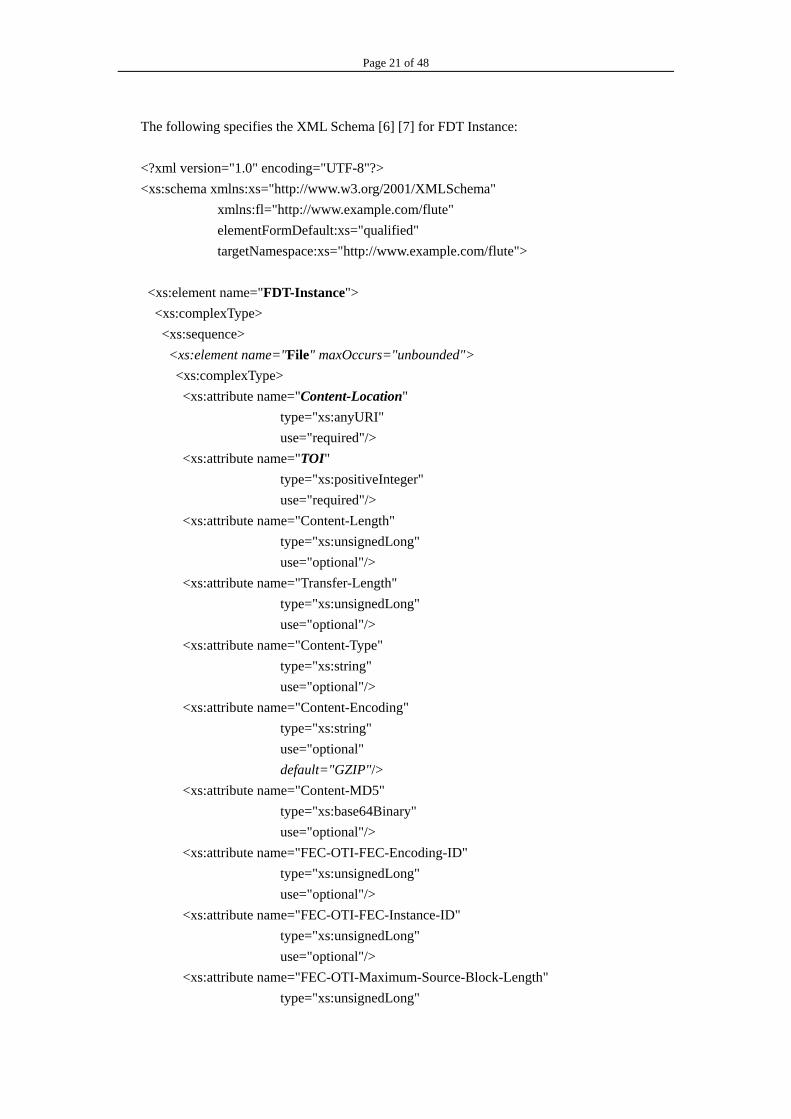
Attributes related to the delivery of file: TOI value that represents the file; FEC Object Transmission Information (including the FEC Encoding ID and, if relevant,
the FEC Instance ID); Size of the transport object carrying the file; Aggregate rate of sending packets to all channels
Attributes related to the file itself:
Name, Identification and Location of file (specified by the URI); MIME media type of file; Size of file; Encoding of file; Message digest of file
Some of these attributes must be included in the file description entry for a file; others are optional, as defined in section 2.2.2.4.2.
2.2.2.2. Outline of FDT
Logically, the FDT is a set of file description entries for files to be delivered in the session. Each file description entry must include the TOI for the file that it describes and the URI identifying the file. The TOI is included in each ALC/LCT data packet during the delivery of the file, and thus the TOI carried in the file description entry is how the receiver determines which ALC/LCT data packets contain information about which file. Each file description entry may also contain one or more descriptors that map the above-mentioned attributes to the file. Each file delivery session must have an FDT that is local to the given session. The FDT must
provide a file description entry mapped to a TOI for each file appearing within the session. An object that is delivered within the ALC session, but not described in the FDT, is not considered a 'file' belonging to the file delivery session. Handling of these unmapped TOIs (TOIs that are not resolved by the FDT) might be to discard this kind of packets.
Within the file delivery session the FDT is delivered as FDT Instances. An FDT Instance contains one or more file description entries of the FDT. Any FDT Instance can be equal to, a subset of, a superset of, or complement any other FDT Instance. A certain FDT Instance may be repeated several times during a session, even after subsequent FDT Instances (with higher FDT Instance ID numbers) have been transmitted. Each FDT Instance contains at least a single file description entry and at most the complete FDT of the file delivery session. A receiver of the file delivery session keeps an FDT database for received file description entries. The receiver maintains the database, for example, upon reception of FDT Instances. Thus, at any given time the contents of the FDT database represent the receiver's current view of the FDT of the file delivery session. Since each receiver behaves independently of other receivers, it should not be assumed that the contents of the FDT database are the same for all the receivers of a given file delivery session.

Page 18 of 48
2.2.2.3. Dynamics of FDT Instances within file delivery session
The following rules define the dynamics of the FDT Instances within a file delivery session: For every file delivered within a file delivery session there must be a file description entry
included in at least one FDT Instance sent within the session. A file description entry contains at a minimum the mapping between the TOI and the URI.
An FDT Instance may appear in any part of the file delivery session and packets for an FDT Instance may be interleaved with packets for other files or other FDT Instances within a session.
The TOI value of '0' must be reserved for delivery of FDT Instances. FDT Instance is identified by the use of a new fixed length LCT Header Extension
EXT_FDT (defined later in this section). Each FDT Instance is uniquely identified within the file delivery session by its FDT Instance ID. Any ALC/LCT packet carrying FDT Instance (indicated by TOI = 0) must include EXT_FDT.
It is recommended that FDT Instance that contains the file description entry for a file is sent prior to the sending of the described file within a file delivery session.
Within a file delivery session, any TOI > 0 MAY be described more than once. An example: previous FDT Instance 0 describes TOI of value '3'. Now, subsequent FDT Instances can either keep TOI '3' unmodified on the table, not include it, or complement the description. However, subsequent FDT Instances must not change the parameters already described for a specific TOI.
An FDT Instance is valid until its expiration time. The expiration time is expressed within the FDT Instance payload as a 32 bit data field. The value of the data field represents the 32 most significant bits of a 64 bit Network Time Protocol (NTP) [4] time value. These 32 bits provide an unsigned integer representing the time in seconds relative to 0 hours 1 January 1900.
The receiver should not use a received FDT Instance to interpret packets received beyond the expiration time of the FDT Instance.
A sender MUST use an expiry time in the future upon creation of an FDT Instance relative to its Sender Current Time (SCT).
Any FEC Encoding ID MAY be used for the sending of FDT Instances. The default is to use FEC Encoding ID 0 for the sending of FDT Instances. (Note that since FEC Encoding ID 0 is the default for FLUTE, this implies that Source Block Number and Encoding Symbol ID lengths both default to 16 bits each.)
Generally, a receiver needs to receive an FDT Instance describing a file before it is able to recover the file itself. In this sense FDT Instances are of higher priority than files. Thus, it is recommended that FDT Instances describing a file be sent with at least as much reliability within a session (more often or with more FEC protection) as the files they describe. In particular, if FDT Instances are longer than one packet payload in length it is recommended that an FEC code that provides protection against loss be used for delivering FDT Instances. How often the description of a file is sent in an FDT Instance or how much FEC protection is provided for each FDT Instance (if the FDT Instance is longer than one packet payload) may be dependent on the particular applications.

Page 19 of 48
2.2.2.4. Structure of FDT Instance packets
FDT Instances are carried in FLUTE packets with TOI = 0 and with an additional required LCT Header extension called the FDT Instance Header. The FDT Instance Header (EXT_FDT) contains the FDT Instance ID that uniquely identifies FDT Instances within a file delivery session. The FDT Instance Header is placed in the same way as any other LCT extension header. There may be other LCT extension headers in use. The LCT extension headers are followed by the FEC Payload ID, and finally the Encoding Symbols for the FDT Instance which contains one or more file description entries. A FDT Instance MAY span several FLUTE packets - the number of FLUTE packets is a function of the file attributes associated with the FDT Instance. The FDT Instance Header is carried in each FLUTE packet carrying the FDT Instance. The FDT Instance Header is identical for all ALC/LCT packets for a particular FDT Instance.
2.2.2.4.1. Format of FDT Instance Header
FDT Instance Header (EXT_FDT) is a new fixed length, ALC PI specific LCT header extension. The Header Extension Type (HET) for the extension is 192. Its format is defined below:
Figure 7 - Format of EXT_FDT Version of FLUTE (V), 4 bits:
It specifies FLUTE version ‘1’ at the present time. FDT Instance ID, 20 bits: For each file delivery session the numbering of FDT Instances starts from '0' and is incremented by one for each subsequent FDT Instance. After reaching the maximum value (2^20-1), the numbering starts again from '0'. When wraparound from 2^20-1 to 0 occurs, 0 is considered higher than 2^20-1. A new FDT Instance reusing a previous FDT Instance ID number, due to wraparound, may not implicitly expire the previous FDT Instance with the same ID. It would be reasonable for FLUTE Senders to only construct and deliver FDT Instances with wraparound IDs after the previous FDT Instance using the same ID has expired.
2.2.2.4.2. Syntax of FDT Instance
The FDT Instance contains file description entries that provide the mapping functionality described in 2.2 above.
The FDT Instance is an XML structure that has a single root element "FDT-Instance". The

Page 20 of 48
"FDT-Instance" element must contain "Expires" attribute, which tells the expiry time of the FDT Instance. In addition, the "FDT-Instance" element may contain the "Complete" attribute (Boolean), which, when TRUE, signals that no new data will be provided in future FDT Instances within this session (i.e., that either FDT Instances with higher ID numbers will not be used or if they are used, will only provide identical file parameters to those already given in this and previous FDT Instances). For example, this may be used to provide a complete list of files in an entire FLUTE session (a "complete FDT"). The "FDT-Instance" element may contain attributes that give common parameters for all files of an FDT Instance. These attributes may also be provided for individual files in the "File" element. Where the same attribute appears in both the "FDT-Instance" and the "File" elements, the value of the attribute provided in the "File" element takes precedence. For each file to be declared in the given FDT Instance there is a single file description entry in the FDT Instance. Each entry is represented by element "File" which is a child element of the FDT Instance structure. The attributes of "File" element in the XML structure represent the attributes given to the file that is delivered in the file delivery session. The value of the XML attribute name corresponds to MIME field name and the XML attribute value corresponds to the value of the MIME field body. Each "File" element must contain at least two attributes "TOI" and "Content-Location". "TOI" must be assigned a valid TOI value as described in section 2.3 above. "Content-Location" must be assigned a valid URI as defined in [5].
In addition to mandatory attributes, the "FDT-Instance" element and the "File" element may contain other attributes of which the following are specifically pointed out.
Where the MIME type is described, the attribute "Content-Type" must be used for the purpose as defined in [5].
Where the length is described, the attribute "Content-Length" must be used for the purpose as defined in [5]. The transfer length is defined to be the length of the object transported in bytes. It is often important to convey the transfer length to receivers, because the source block structure needs to be known for the FEC decoder to be applied to recover source blocks of the file, and the transfer length is often needed to properly determine the source block structure of the file. There generally will be a difference between the length of the original file and the transfer length if content encoding is applied to the file before transport, and thus the "Content-Encoding" attribute is used. If the file is not content encoded before transport (and thus the "Content-Encoding" attribute is not used) then the transfer length is the length of the original file, and in this case the "Content-Length" is also the transfer length. However, if the file is content encoded before transport (and thus the "Content-Encoding" attribute is used), e.g., if compression is applied before transport to reduce the number of bytes that need to be transferred, then the transfer length is generally different than the length of the original file, and in this case the attribute "Transfer-Length" may be used to carry the transfer length.
Where the content encoding scheme is described, the attribute "Content-Encoding" MUST be used for the purpose as defined in [5].
Where the MD5 message digest is described, the attribute "Content-MD5" MUST be used for the purpose as defined in [5].
The FEC Object Transmission Information attributes as described in section 2.3.
Page 21 of 48
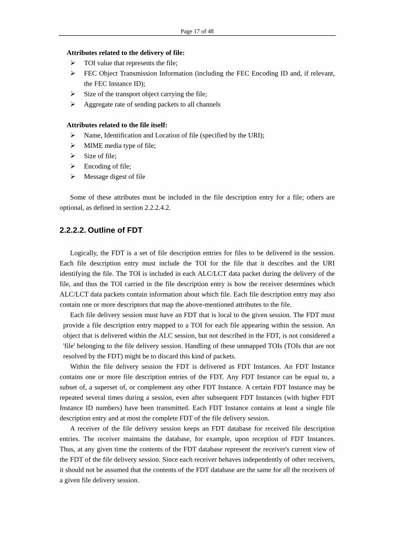
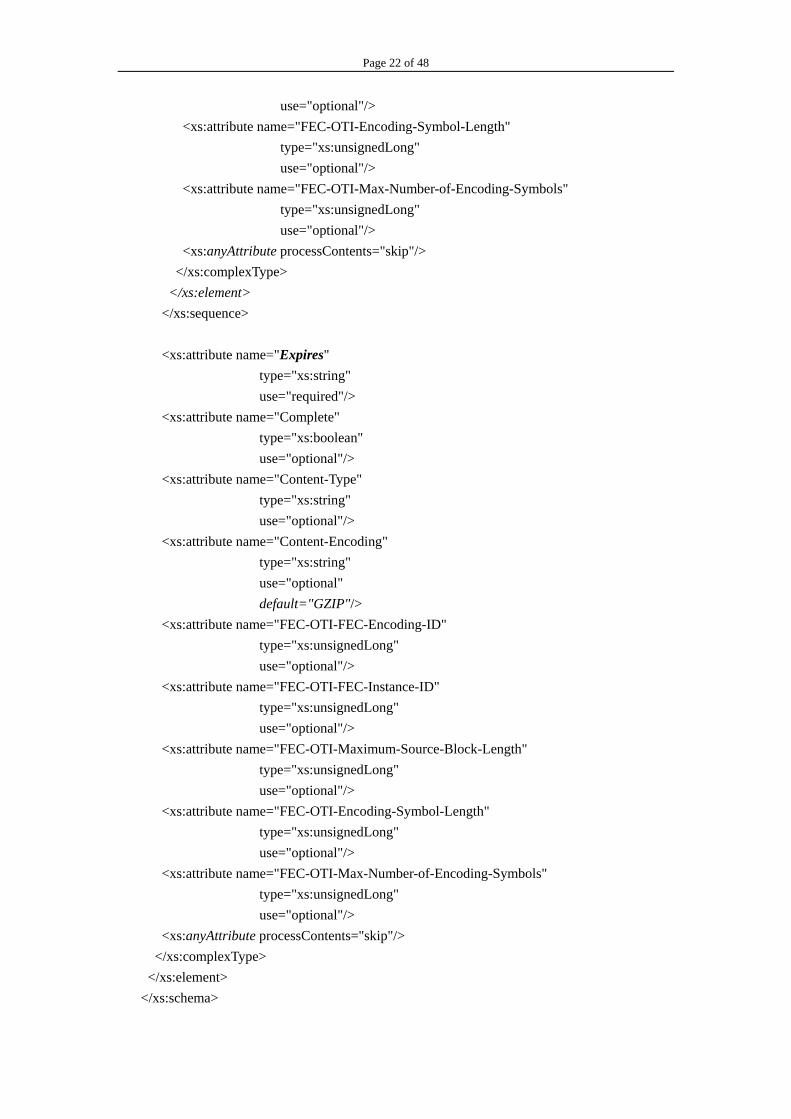
The following specifies the XML Schema [6] [7] for FDT Instance: <?xml version="1.0" encoding="UTF-8"?> <xs:schema xmlns:xs="http://www.w3.org/2001/XMLSchema" xmlns:fl="http://www.example.com/flute" elementFormDefault:xs="qualified" targetNamespace:xs="http://www.example.com/flute">
<xs:element name="FDT-Instance"> <xs:complexType> <xs:sequence> <xs:element name="File" maxOccurs="unbounded"> <xs:complexType> <xs:attribute name="Content-Location" type="xs:anyURI" use="required"/> <xs:attribute name="TOI" type="xs:positiveInteger" use="required"/> <xs:attribute name="Content-Length" type="xs:unsignedLong" use="optional"/> <xs:attribute name="Transfer-Length" type="xs:unsignedLong" use="optional"/> <xs:attribute name="Content-Type" type="xs:string" use="optional"/> <xs:attribute name="Content-Encoding" type="xs:string" use="optional"
default="GZIP"/> <xs:attribute name="Content-MD5" type="xs:base64Binary" use="optional"/> <xs:attribute name="FEC-OTI-FEC-Encoding-ID" type="xs:unsignedLong" use="optional"/> <xs:attribute name="FEC-OTI-FEC-Instance-ID" type="xs:unsignedLong" use="optional"/> <xs:attribute name="FEC-OTI-Maximum-Source-Block-Length" type="xs:unsignedLong"
Page 22 of 48
use="optional"/> <xs:attribute name="FEC-OTI-Encoding-Symbol-Length" type="xs:unsignedLong" use="optional"/> <xs:attribute name="FEC-OTI-Max-Number-of-Encoding-Symbols" type="xs:unsignedLong" use="optional"/> <xs:anyAttribute processContents="skip"/> </xs:complexType> </xs:element> </xs:sequence> <xs:attribute name="Expires" type="xs:string" use="required"/> <xs:attribute name="Complete" type="xs:boolean" use="optional"/> <xs:attribute name="Content-Type" type="xs:string" use="optional"/> <xs:attribute name="Content-Encoding" type="xs:string" use="optional"
default="GZIP"/> <xs:attribute name="FEC-OTI-FEC-Encoding-ID" type="xs:unsignedLong" use="optional"/> <xs:attribute name="FEC-OTI-FEC-Instance-ID" type="xs:unsignedLong" use="optional"/> <xs:attribute name="FEC-OTI-Maximum-Source-Block-Length" type="xs:unsignedLong" use="optional"/> <xs:attribute name="FEC-OTI-Encoding-Symbol-Length" type="xs:unsignedLong" use="optional"/> <xs:attribute name="FEC-OTI-Max-Number-of-Encoding-Symbols" type="xs:unsignedLong" use="optional"/> <xs:anyAttribute processContents="skip"/> </xs:complexType> </xs:element> </xs:schema>
Page 23 of 48
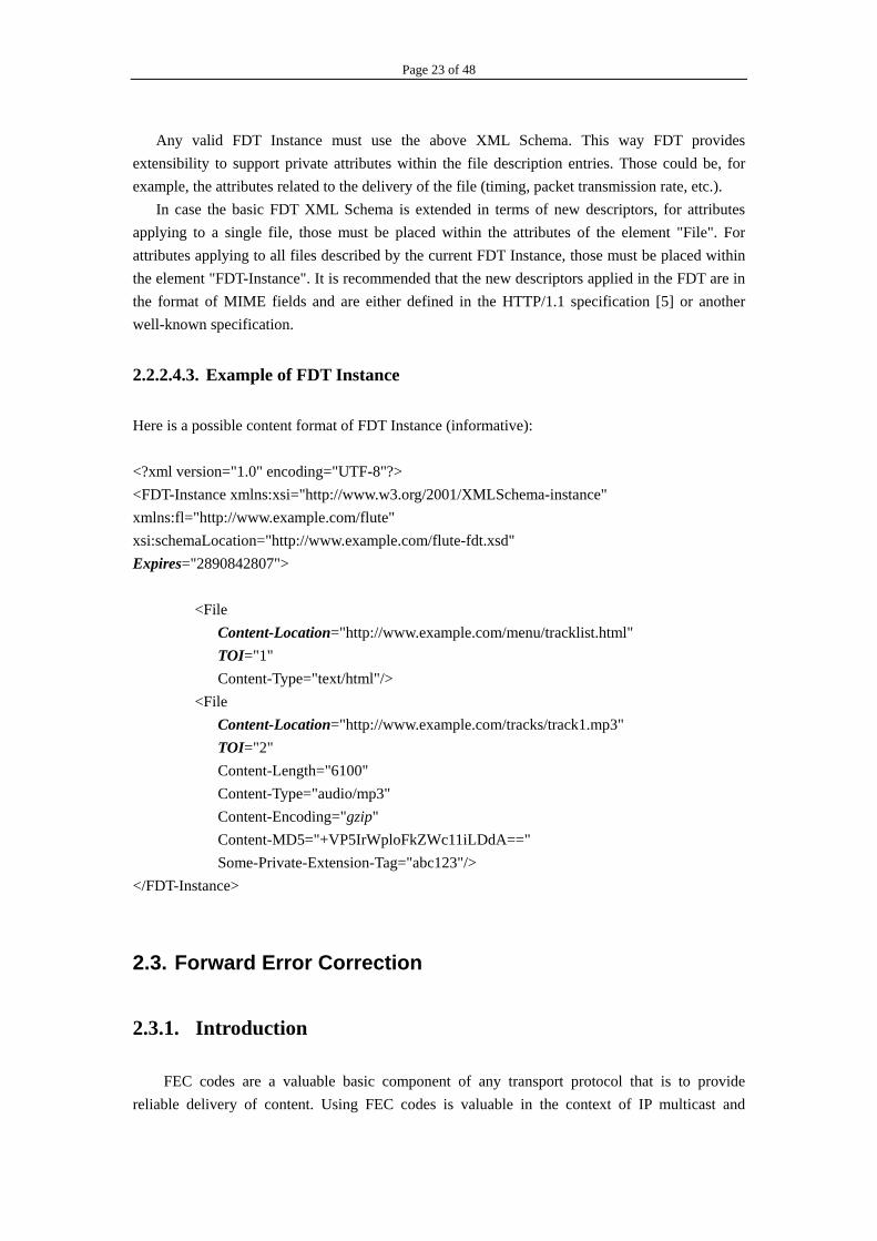
Any valid FDT Instance must use the above XML Schema. This way FDT provides extensibility to support private attributes within the file description entries. Those could be, for example, the attributes related to the delivery of the file (timing, packet transmission rate, etc.). In case the basic FDT XML Schema is extended in terms of new descriptors, for attributes applying to a single file, those must be placed within the attributes of the element "File". For attributes applying to all files described by the current FDT Instance, those must be placed within the element "FDT-Instance". It is recommended that the new descriptors applied in the FDT are in the format of MIME fields and are either defined in the HTTP/1.1 specification [5] or another well-known specification.
2.2.2.4.3. Example of FDT Instance
Here is a possible content format of FDT Instance (informative): <?xml version="1.0" encoding="UTF-8"?> <FDT-Instance xmlns:xsi="http://www.w3.org/2001/XMLSchema-instance" xmlns:fl="http://www.example.com/flute" xsi:schemaLocation="http://www.example.com/flute-fdt.xsd" Expires="2890842807"> <File Content-Location="http://www.example.com/menu/tracklist.html" TOI="1" Content-Type="text/html"/> <File Content-Location="http://www.example.com/tracks/track1.mp3" TOI="2" Content-Length="6100" Content-Type="audio/mp3" Content-Encoding="gzip" Content-MD5="+VP5IrWploFkZWc11iLDdA==" Some-Private-Extension-Tag="abc123"/> </FDT-Instance>
2.3. Forward Error Correction
2.3.1. Introduction
FEC codes are a valuable basic component of any transport protocol that is to provide reliable delivery of content. Using FEC codes is valuable in the context of IP multicast and
Page 24 of 48
reliable delivery because FEC encoding symbols can be useful to all receivers for reconstructing content even when the receivers have received different encoding symbols. Furthermore, FEC codes can ameliorate or even eliminate the need for feedback from receivers to senders to request retransmission of lost packets, which is quite suitable for FLUTE, a unidirectional file delivery protocol.
To use FEC codes in FLUTE, we must make it clear what information is needed for FEC codes, i.e. FEC Information. Besides, the content of FEC Information, packets in which this information is carried, formats of these packets, as well as the coding schemes that can be used, are all in our consideration.
When it comes to FLUTE, how the FEC Payload ID and FEC Object Transmission Information should be communicated between senders and receivers is a major concern. The FEC Payload ID is carried in the header of each FLUTE packet. The format of FEC Payload ID for each code schemes is defined in section 4. In order to delivery the FEC Object Transmission Information in band with other ordinary information, there are two methods: use of ALC specific LCT extension header EXT_FTI [16] and the use of FDT.
Generally speaking, using FDT is an easy way to delivery FEC Object Transmission Information in band. However, in case the packets which carry FDT instances are also encoded, the use of ALC specific LCT extension header EXT_FTI [16] is the only way to convey the required information in band.
In the following sections, we will discuss these factors in details.
2.3.2. FEC Information
This section describes FEC information that is either to be sent out-of-band or in packets. The FEC information is associated with transmission of data about a particular object. There are three classes of packets that may contain FEC information: data packets, session-control packets and feedback packets. They generally contain different kinds of FEC information. Note that FLUTE does not use feedback packets. Data packets may sometimes serve as session-control packets as well; both data and session-control packets generally travel downstream from the sender towards receivers and are sent to a multicast channel or to a specific receiver using unicast.
This section specifies the FEC information that must be carried in data packets and the other FEC information that must be communicated either out-of-band or in data packets. This section does not specify out-of-band methods nor does it specify the way out-of-band FEC information is associated with FEC information carried in data packets. These methods must be specified in a complete protocol instantiation that uses the FEC building block. FEC information is classified as follows:
1) FEC Encoding ID Identifies the FEC encoder being used and allows receivers to select the appropriate FEC
decoder. The value of the FEC Encoding ID MUST be the same for all transmission of data related to a particular object, but MAY vary across different transmissions of data about different objects, even if transmitted to the same set of multicast channels and/or using a single upper-layer session. The FEC Encoding ID is subject to IANA registration.
2) FEC Instance ID

Page 25 of 48
Provides a more specific identification of the FEC encoder being used for an Under-Specified FEC scheme. This value is not used for Fully-Specified FEC schemes. (See section 2.3.2.1&2.3.2.2 for the definition of Under-Specified and Fully-Specified FEC schemes.) The FEC Instance ID is scoped by the FEC Encoding ID, and is subject to IANA registration.
3) FEC Payload ID Identifies the encoding symbol(s) in the payload of the packet. The types and lengths of the
fields in the FEC Payload ID, i.e., the format of the FEC Payload ID, are determined by the FEC Encoding ID. The full specification of each field MUST be uniquely determined by the FEC Encoding ID for Fully-Specified FEC schemes, and MUST be uniquely determined by the combination of the FEC Encoding ID and the FEC Instance ID for Under-Specified FEC schemes. As an example, for the Under-Specified FEC scheme with FEC Encoding ID 129 defined in section 2.3.4.2, the fields in the FEC Payload ID are a 32-bit Source Block Number followed by a 32-bit Encoding Symbol ID, where the full specification of both of these fields depends on the FEC Instance ID.
4) FEC Object Transmission Information This is information regarding the encoding of a specific object needed by the FEC decoder.
As an example, for the Under-Specified FEC scheme with FEC Encoding ID 129 defined in section 2.3.2.2, this information might include the lengths of the different source blocks that make up the object and the overall object length. This might also include specific parameters of the FEC encoder.
2.3.2.1. Fully-Specified FEC Schemes
An FEC scheme is a Fully-Specified FEC scheme if the encoding scheme is formally and fully specified, in a way that independent implementors can implement both encoder and decoder from a specification that is an IETF RFC. The FEC Encoding ID uniquely identifies a Fully-Specified FEC scheme. Companion documents of this specification may specify Fully-Specified FEC schemes and associate them with FEC Encoding ID values.
These documents MUST also specify a format for the FEC Payload ID and specify the information in the FEC Object Transmission Information.
The range 0-127 for the values of FEC Encoding IDs is reserved for Fully-Specified FEC schemes.
2.3.2.2. Under-Specified FEC Schemes
It is possible that a FEC scheme may not be a Fully-Specified FEC scheme, because either a specification is simply not available or a party exists that owns the encoding scheme and is not willing to disclose the algorithm or specification. We refer to such an FEC encoding schemes as an Under-Specified FEC scheme. The following holds for an Under-Specified FEC scheme:
The fields and their formats of the FEC Payload ID and the specific information in the FEC Object Transmission Information MUST be defined for the Under-Specified FEC scheme.
A value for the FEC Encoding ID MUST be reserved and associated with the fields and their formats of the FEC Payload ID and the specific information in the FEC Object

Page 26 of 48
Transmission Information. An already reserved FEC Encoding ID value MUST be reused if the associated FEC Payload ID has the same fields and formats and the FEC Object Transmission Information has same information as the ones needed for the new Under-Specified FEC scheme.
A value for the FEC Instance ID MUST be reserved. An Under-Specified FEC scheme is fully identified by the tuple (FEC Encoding ID, FEC
Instance ID). The tuple MUST identify a single scheme that has at least one implementation. The party that owns this tuple MUST be able to provide information on how to obtain the Under-Specified FEC scheme identified by the tuple, e.g., a pointer to a publicly available reference-implementation or the name and contacts of a company that sells it, either separately or embedded in another product.
Different Under-Specified FEC schemes that share the same FEC Encoding ID -- but have different FEC Instance IDs -- also share the same fields and corresponding formats of the FEC Payload ID and specify the same information in the FEC Object Transmission Information.
The range 128-255 for the values of FEC Encoding IDs is reserved for Under-Specified FEC schemes.
2.3.3. FEC Codes
2.3.3.1. Overview
In the general literature, FEC refers to the ability to overcome both erasures (losses) and bit-level corruption. However, in the case of an IP multicast protocol, the network layers will detect corrupted packets and discard them or the transport layers can use packet authentication to discard corrupted packets. Therefore the primary application of FEC codes to IP multicast protocols is as an erasure code. The payloads are generated and processed using an FEC erasure encoder and objects are reassembled from reception of packets containing the generated encoding using the corresponding FEC erasure decoder.
The input to an FEC encoder is some number k of equal length source symbols. The FEC encoder generates some number of encoding symbols that are of the same length as the source symbols. The chosen length of the symbols can vary upon each application of the FEC encoder, or it can be fixed. These encoding symbols are placed into packets for transmission. The number of encoding symbols placed into each packet can vary on a per packet basis, or a fixed number of symbols (often one) can be placed into each packet. Also, in each packet is placed enough information to identify the particular encoding symbols carried in that packet. Upon receipt of packets containing encoding symbols, the receiver feeds these encoding symbols into the corresponding FEC decoder to recreate an exact copy of the k source symbols. Ideally, the FEC decoder can recreate an exact copy from any k of the encoding symbols.
2.3.3.2. Simple codes
There are some very simple codes that are effective for repairing packet loss under very low loss conditions. For example, to provide protection from a single loss is to partition the object into

Page 27 of 48
fixed size source symbols and then add a redundant symbol that is the parity (XOR) of all the source symbols. The size of a source symbol is chosen so that it fits perfectly into the payload of a packet, i.e. if the packet payload is 512 bytes then each source symbol is 512 bytes. The header of each packet contains enough information to identify the payload.
Slightly more sophisticated ways of adding redundant symbols using parity can also be used. For example, one can group a block consisting of k source symbols in an object into a p x p square matrix, where p = sqrt(k). Then, for each row a redundant symbol is added that is the parity of all the source symbols in the row. Similarly, for each column a redundant symbol is added that is the parity of all the source symbols in the column. Then, any row of the matrix can be recovered from any p of the p+1 symbols in the row, and similarly for any column. Higher dimensional product codes using this technique can also be used. However, one must be wary of using these constructions without some thought towards the possible loss patterns of symbols. Ideally, the property that one would like to obtain is that if k source symbols are encoded into n encoding symbols (the encoding symbols consist of the source symbols and the redundant symbols) then the k source symbols can be recovered from any k of the n encoding symbols. Using the simple constructions described above does not yield codes that come close to obtaining this ideal behavior.
2.3.3.3. Small block FEC codes
Reliable IP multicast protocols may use a block (n, k) FEC code [3]. For such codes, k source symbols are encoded into n > k encoding symbols, such that any k of the encoding symbols can be used to reassemble the original k source symbols. Thus, these codes have no reception overhead when used to encode the entire object directly. Block codes are usually systematic, which means that the n encoding symbols consist of the k source symbols and n-k redundant symbols generated from these k source symbols, where the size of a redundant symbol is the same as that for a source symbol. For example, the first simple code (XOR) described in the previous subsection is a (k+1, k) code. In general, the freedom to choose n larger than k+1 is desirable, as this can provide much better protection against losses. A popular example of these types of codes is a class of Reed-Solomon codes, which are based on algebraic methods using finite fields. Implementations of (n, k) FEC erasure codes are efficient enough to be used by personal computers [4]. For example, [5] describes an implementation where the encoding and decoding speeds decay as C/j, where the constant C is on the order of 10 to 80 Mbytes/second for Pentium class machines of various vintages and j is upper bounded by min(k, n-k).
In practice, the values of k and n must be small (for example below 256) for such FEC codes as large values make encoding and decoding prohibitively expensive. As many objects are longer than k symbols for reasonable values of k and the symbol length (e.g. larger than 16 kilobyte for k = 16 using 1 kilobyte symbols), they can be divided into a number of source blocks. Each source block consists of some number k of source symbols, where k may vary between different source blocks.
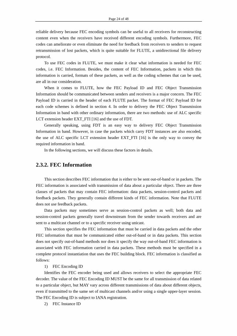
The FEC encoder is used to encode a k source symbol source block into an encoding symbol encoding block, where the number n of encoding symbols in the encoding block may vary for each source block. For a receiver to completely recover the object, for each source block consisting of k source symbols, k distinct encoding symbols (i.e., with different encoding symbol
Page 28 of 48
IDs) must be received from the corresponding encoding block. For some encoding blocks, more encoding symbols may be received than there are source symbols in the corresponding source block, in which case the excess encoding symbols are discarded. An example encoding structure is shown in Figure 8.
Figure 8- The encoding structure for an object divided into two source blocks consisting of 8 source symbols each, and the FEC encoder is used to generate 2 additional redundant symbols (10 encoding symbols in total) for each of the two source blocks.
2.3.3.4. Large block FEC codes
Tornado codes [6], [7], [8], [9], [10] are large block FEC codes that provide an alternative to small block FEC codes. An (n, k) Tornado code requires slightly more than k out of n encoding symbols to recover k source symbols, i.e., there is a small reception overhead. The benefit of the small cost of non-zero reception overhead is that the value of k may be on the order of tens of thousands and still the encoding and decoding are efficient. Because of memory considerations, in practice the value of n is restricted to be a small multiple of k, e.g., n = 2k. For example, [11] describes an implementation of Tornado codes where the encoding and decoding speeds are tens of megabytes per second for Pentium class machines of various vintages when k is in the tens of thousands and n = 2k. The reception overhead for such values of k and n is in the 5-10% range. Tornado codes require a large amount of out of band information to be communicated to all senders and receivers for each different object length, and require an amount of memory on the encoder and decoder which is proportional to the object length times 2n/k.
Tornado codes are designed to have low reception overhead on average with respect to
Page 29 of 48
reception of a random portion of the encoding packets. Thus, to ensure that a receiver can reassemble the object with low reception overhead, the packets are permuted into a random order before transmission.
2.3.3.5. Expandable block FEC codes
All of the FEC codes described up to this point are block codes. There is a different type of FEC codes that we call expandable FEC codes. Like block codes, an expandable FEC encoder operates on an object of known size that is partitioned into equal length source symbols. Unlike block codes, there is no predetermined number of encoding symbols that can be generated for expandable FEC codes. Instead, an expandable FEC encoder can generate as few or as many unique encoding symbols as required on demand.
LT codes [12], [13], [14], [15] are an example of large expandable FEC codes with a small reception overhead. An LT encoder uses randomization to generate each encoding symbol randomly and independently of all other encoding symbols. Like Tornado codes, the number of source symbols k may be very large for LT codes, i.e., on the order of tens to hundreds of thousands, and the encoder and decoder run efficiently in software. For example the encoding and decoding speeds for LT codes are in the range 3-20 megabytes per second for Pentium class machines of various vintages when k is in the high tens of thousands. An LT encoder can generate as few or as many encoding symbols as required on demand. When a new encoding symbol is to be generated by an LT encoder, it is based on a randomly chosen encoding symbol ID that uniquely describes how the encoding symbol is to be generated from the source symbols. In general, each encoding symbol ID value corresponds to a unique encoding symbol, and thus the space of possible encoding symbols is approximately four billion if for example the encoding symbol ID is 4 bytes. Thus, the chance that a particular encoding symbol is the same as any other particular encoding symbol is inversely proportional to the number of possible encoding symbol IDs. An LT decoder has the property that with very high probability the receipt of any set of slightly more than k randomly and independently generated encoding symbols is sufficient to reassemble the k source symbols. For example, when k is on the order of tens to hundreds of thousands the reception overhead is less than 5% with no failures in hundreds of millions of trials under any loss conditions.
Because encoding symbols are randomly and independently generated by choosing random encoding symbol IDs, LT codes have the property that encoding symbols for the same k source symbols can be generated and transmitted from multiple senders and received by a receiver and the reception overhead and the decoding time is the same as if though all the encoding symbols were generated by a single sender. The only requirement is that the senders choose their encoding symbol IDs randomly and independently of one another.
2.3.4. Packet Header Fields
This section specifies the FEC Encoding ID, the associated FEC Payload ID format, and the specific information in the FEC Object Transmission Information for a number of known

Page 30 of 48
Under-Specified FEC schemes. Under-Specified FEC schemes that use the same FEC Payload ID fields, formats, and specific information in the FEC Object Transmission Information (as for one of the FEC Encoding IDs specified in this section) MUST use the corresponding FEC Encoding ID. Other FEC Encoding IDs may be specified for other Under- Specified FEC schemes in companion documents.
2.3.4.1. Small Block, Large Block and Expandable FEC Codes
This subsection reserves the FEC Encoding ID value 128 for the Under-Specified FEC schemes described in [1] that are called Small Block FEC codes, Large Block FEC codes and Expandable FEC codes.
The FEC Payload ID is composed of a Source Block Number and an Encoding Symbol ID structured as follows:
Figure 9- Format of FEC Payload ID 128
The Source Block Number identifies from which source block of the object the encoding
symbol(s) in the payload are generated. These blocks are numbered consecutively from 0 to N-1, where N is the number of source blocks in the object.
The Encoding Symbol ID identifies which specific encoding symbol(s) generated from the source block are carried in the packet payload. The exact details of the correspondence between Encoding Symbol IDs and the encoding symbol(s) in the packet payload are dependent on the particular encoding algorithm used as identified by the FEC Encoding ID and by the FEC Instance ID, and these details may be proprietary.
The FEC Object Transmission Information has the following specific information: The FEC Encoding ID 128. The FEC Instance ID associated with the FEC Encoding ID 128 to be used. The total length of the object in bytes. The number of source blocks that the object is partitioned into, and the length of each
source block in bytes.
2.3.4.2. Small Block Systematic FEC Codes
This subsection reserves the FEC Encoding ID value 129 for the Under-Specified FEC schemes described in [4] that are called Small Block Systematic FEC codes. For Small Block Systematic FEC codes, each source block is of length at most 65536 source symbols.
Although these codes can generally be accommodated by the FEC Encoding ID described in section 2.3.2, a specific FEC Encoding ID is defined for Small Block Systematic FEC codes to allow more flexibility and to retain header compactness. The small source block length and small
Page 31 of 48
expansion factor that often characterize systematic codes may require the data source to frequently change the source block length. To allow the dynamic variation of the source block length and to communicate it to the receivers with low overhead, the block length is included in the FEC Payload ID.
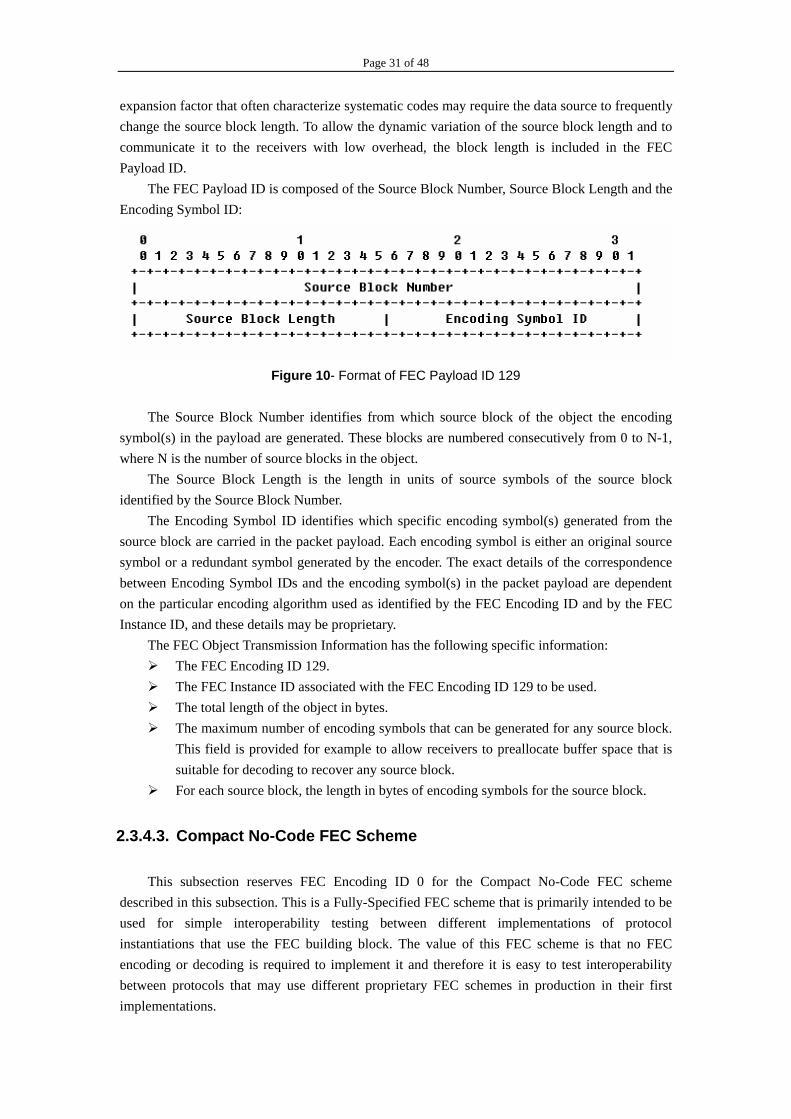
The FEC Payload ID is composed of the Source Block Number, Source Block Length and the Encoding Symbol ID:
Figure 10- Format of FEC Payload ID 129
The Source Block Number identifies from which source block of the object the encoding symbol(s) in the payload are generated. These blocks are numbered consecutively from 0 to N-1, where N is the number of source blocks in the object. The Source Block Length is the length in units of source symbols of the source block identified by the Source Block Number.
The Encoding Symbol ID identifies which specific encoding symbol(s) generated from the source block are carried in the packet payload. Each encoding symbol is either an original source symbol or a redundant symbol generated by the encoder. The exact details of the correspondence between Encoding Symbol IDs and the encoding symbol(s) in the packet payload are dependent on the particular encoding algorithm used as identified by the FEC Encoding ID and by the FEC Instance ID, and these details may be proprietary.
The FEC Object Transmission Information has the following specific information: The FEC Encoding ID 129. The FEC Instance ID associated with the FEC Encoding ID 129 to be used. The total length of the object in bytes. The maximum number of encoding symbols that can be generated for any source block.
This field is provided for example to allow receivers to preallocate buffer space that is suitable for decoding to recover any source block.
For each source block, the length in bytes of encoding symbols for the source block.
2.3.4.3. Compact No-Code FEC Scheme
This subsection reserves FEC Encoding ID 0 for the Compact No-Code FEC scheme described in this subsection. This is a Fully-Specified FEC scheme that is primarily intended to be used for simple interoperability testing between different implementations of protocol instantiations that use the FEC building block. The value of this FEC scheme is that no FEC encoding or decoding is required to implement it and therefore it is easy to test interoperability between protocols that may use different proprietary FEC schemes in production in their first implementations.

Page 32 of 48
The FEC Payload ID format for FEC Encoding ID 0 is described as follows:
Figure 11- Format of FEC Payload ID 0 & 130
The 16-bit Source Block Number is used to identify from which source block of the object the encoding symbol in the payload of the packet is generated. There are two possible modes: In the unique SBN mode each source block within the object has a unique Source Block Number associated with it, and in the non-unique SBN mode the same Source Block Number may be used for more than one source block within the object. Which mode is being used for an object is outside the scope of this document and MUST be communicated, either explicitly or implicitly, out-of-band to receivers. The FEC Object Transmission Information has the following specific information:
The FEC Encoding ID 0. For each source block of the object, the length in bytes of the encoding symbol carried
in the packet payload. This length MUST be the same for all packets sent for the same source block, but MAY be different for different source blocks in the same object.
For each source block of the object, the length of the source block in bytes. Typically, each source block for the object has the same length and thus only one length common to all source blocks need be communicated, but this is not a requirement. For convenience, the source block length MAY be a multiple of the length of the encoding symbol carried in one packet payload.
2.3.4.4. Compact FEC Scheme
This subsection reserves FEC Encoding ID 130 for the Compact FEC scheme that is described in this subsection. This is an Under-Specified FEC scheme. This FEC scheme is similar in spirit to the Compact No-Code FEC scheme, except that a non-trivial FEC encoding (that is Under-Specified) may be used to generate encoding symbol(s) placed in the payload of each packet and a corresponding FEC decoder may be used to produce the source block from received packets.
The FEC Payload ID format for FEC Encoding ID 130 is the same as described in subsection 2.3.4.3. The FEC Object Transmission Information has the following specific information:
The FEC Encoding ID 130. The FEC Instance ID associated with the FEC Encoding ID 130 to be used. For each source block of the object, the aggregate length of the encoding symbol(s)
carried in one packet payload. This length MUST be the same for all packets sent for the same source block, but MAY be different for different source blocks in the same object.
For each source block of the object, the length of the source block in bytes. Typically, each source block for the object has the same length and thus only one length common to all source blocks need to be communicated, but this is not a requirement. For
Page 33 of 48
convenience, the source block length MAY be a multiple of the aggregate length of the encoding symbol(s) carried in one packet payload.
2.3.5. Delivering FEC OTI in FLUTE
FLUTE inherits the use of FEC building block [1] from ALC. When using FLUTE for file delivery over ALC the FEC Object Transmission Information (OTI) MUST be delivered in-band within the file delivery session. In this section, two methods are specified for FLUTE for this purpose: the use of ALC specific LCT extension header EXT_FTI [16] and the use of FDT.
The receiver of file delivery session MUST support delivery of FEC Object Transmission Information using the EXT_FTI for the FDT Instances carried using TOI value 0. For the TOI values other than 0 the receiver MUST support both methods: the use of EXT_FTI and the use of FDT.
The FEC Object Transmission Information that needs to be delivered to receivers MUST be exactly the same whether it is delivered using EXT_FTI or using FDT (or both). section 2.3.5.1 describes the required FEC Object Transmission Information that MUST be delivered to receivers for various FEC Encoding IDs. In addition, it describes the delivery using EXT_FTI. Section 2.3.5.2 describes the delivery using FDT.
The FEC Object Transmission Information regarding a given TOI may be available from several sources. In this case, it is RECOMMENDED that the receiver of the file delivery session prioritizes the sources in the following way (in the order of decreasing priority).
1. FEC Object Transmission Information that is available in EXT_FTI. 2. FEC Object Transmission Information that is available in the FDT.
2.3.5.1. Use of EXT_FTI for delivery of FEC OTI
As specified in [16], the EXT_FTI header extension is intended to carry the FEC Object Transmission Information for an object in-band. It is left up to individual implementations to decide how frequently and in which FLUTE packets the EXT_FTI header extension is included. In environments with higher packet loss rate, the EXT_FTI might need to be included more frequently in FLUTE packets than in environments with low error probability. The EXT_FTI MUST be included in at least one sent FLUTE packet for each FDT Instance.
The ALC specification does not define the format or the processing of the EXT_FTI header extension. The following sections specify EXT_FTI when used in FLUTE.
In FLUTE, the FEC Encoding ID (8 bits) is carried in the Codepoint field of the ALC/LCT header.
2.3.5.1.1. General EXT_FTI format
The general EXT_FTI format specifies the structure and those attributes of FEC Object Transmission Information that are applicable to any FEC Encoding ID.
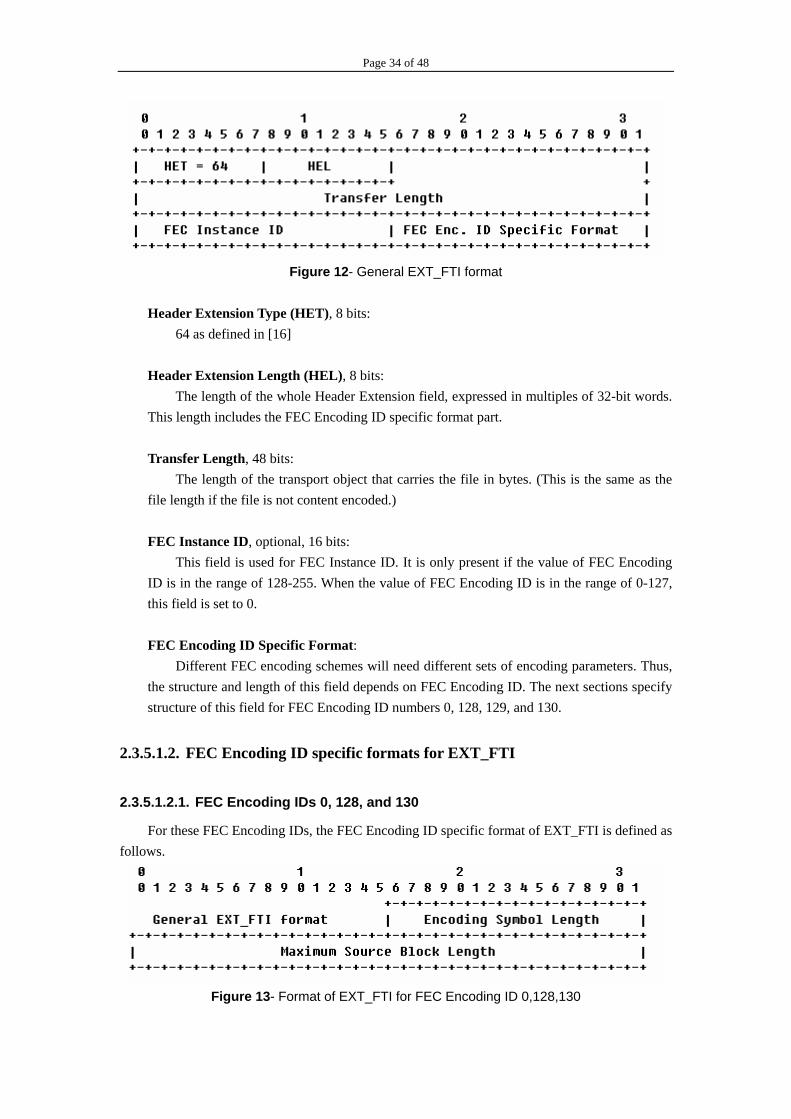
Page 34 of 48
Figure 12- General EXT_FTI format
Header Extension Type (HET), 8 bits:
64 as defined in [16]
Header Extension Length (HEL), 8 bits: The length of the whole Header Extension field, expressed in multiples of 32-bit words.
This length includes the FEC Encoding ID specific format part. Transfer Length, 48 bits:
The length of the transport object that carries the file in bytes. (This is the same as the file length if the file is not content encoded.)
FEC Instance ID, optional, 16 bits:
This field is used for FEC Instance ID. It is only present if the value of FEC Encoding ID is in the range of 128-255. When the value of FEC Encoding ID is in the range of 0-127, this field is set to 0.
FEC Encoding ID Specific Format:
Different FEC encoding schemes will need different sets of encoding parameters. Thus, the structure and length of this field depends on FEC Encoding ID. The next sections specify structure of this field for FEC Encoding ID numbers 0, 128, 129, and 130.
2.3.5.1.2. FEC Encoding ID specific formats for EXT_FTI
2.3.5.1.2.1. FEC Encoding IDs 0, 128, and 130
For these FEC Encoding IDs, the FEC Encoding ID specific format of EXT_FTI is defined as follows.
Figure 13- Format of EXT_FTI for FEC Encoding ID 0,128,130

Page 35 of 48
Encoding Symbol Length, 16 bits:
Length of Encoding Symbol in bytes. All Encoding Symbols of a transport object MUST be equal to this length, with the optional
exception of the last source symbol of the last source block (so that redundant padding is not mandatory in this last symbol). This last source symbol MUST be logically padded out with zeroes when another Encoding Symbol is computed based on this source symbol to ensure the same interpretation of this Encoding Symbol value by the sender and receiver. However, this padding does not actually need to be sent with the data of the last source symbol. Maximum Source Block Length, 32 bits:
The maximum number of source symbols per source block. This EXT_FTI specification requires that an algorithm is known to both sender and receivers
for determining the size of all source blocks of the transport object that carries the file identified by the TOI (or within the FDT Instance identified by the TOI and the FDT Instance ID). The algorithm SHOULD be the same for all files using the same FEC Encoding ID within a session.
2.3.5.1.2.2. FEC Encoding ID 129
Small Block Systematic FEC (Under-Specified): The FEC Encoding ID specific format of EXT_FTI is defined as follows.
Figure 14- Format of EXT_FTI for FEC Encoding ID 129
Encoding Symbol Length, 16 bits:
Length of Encoding Symbol in bytes. All Encoding Symbols of a transport object MUST be equal to this length, with the
optional exception of the last source symbol of the last source block (so that redundant padding is not mandatory in this last symbol). This last source symbol MUST be logically padded out with zeroes when another Encoding Symbol is computed based on this source symbol to ensure the same interpretation of this Encoding Symbol value by the sender and receiver. However, this padding need not be actually sent with the data of the last source symbol.
Maximum Source Block Length, 16 bits:
The maximum number of source symbols per source block.
Maximum Number of Encoding Symbols, 16 bits: Maximum number of Encoding Symbols that can be generated for a source block.
Page 36 of 48
This EXT_FTI specification requires that an algorithm is known to both sender and receivers for determining the size of all source blocks of the transport object that carries the file identified by the TOI (or within the FDT Instance identified by the TOI and the FDT Instance ID). The algorithm SHOULD be the same for all files using the same FEC Encoding ID within a session.
2.3.5.2. Use of FDT for delivery of FEC OTI
The FDT delivers FEC Object Transmission Information (OTI) for each file using an appropriate attribute within the "FDT-Instance" or the "File" element of the FDT structure. For future FEC Encoding IDs, if the attributes listed below do not fulfill the needs of describing the FEC Object Transmission Information then additional new attributes MAY be used.
"Transfer-Length" is semantically equivalent with the field Transfer Length" of EXT_FTI.
"FEC-OTI-FEC-Encoding-ID" is semantically equivalent with the field "FEC Encoding ID" as carried in the Codepoint field of the ALC/LCT header.
"FEC-OTI-FEC-Instance-ID" is semantically equivalent with the field "FEC Instance ID" of EXT_FTI.
"FEC-OTI-Maximum-Source-Block-Length" is semantically equivalent with the field "Maximum Source Block Length" of EXT_FTI for FEC Encoding IDs 0, 128 and 130, and semantically equivalent with the field "Maximum Source Block Length" of EXT_FTI for FEC Encoding ID 129.
"FEC-OTI-Encoding-Symbol-Length" is semantically equivalent with he field "Encoding Symbol Length" of EXT_FTI for FEC Encoding IDs 0, 128, 129 and 130.
"FEC-OTI-Max-Number-of-Encoding-Symbols" is semantically equivalent with the field "Maximum Number of Encoding Symbols" of EXT_FTI for FEC Encoding ID 129.
2.4. Multiple-rate Congestion Control
2.4.1. Introduction
Within today's information society, widespread use of Internet makes the economy of multicast transport attractive. Important applications exist for a reliable multicast service. The current Internet multicast model offers best-effort many-to-many delivery service and offers no guarantees. One-to-many and few-to-few services, which apply to FLUTE application protocol, may become more important in the future.
Different multicast applications have widely different requirements for reliability. For example, some applications require that message delivery obey a total ordering while others (e.g. FLUTE) do not. Some applications (e.g. supported by FLUTE) have partial or all the members sending data while others have only one data source. Some applications are restricted to small fixed-membership multicast groups, while other applications need to scale dynamically to
Page 37 of 48
thousands or tens of thousands of members (or possibly more, e.g. FLUTE). Some applications have stringent delay requirements, while others (e.g. FLUTE) do not. Some applications (e.g. File transfer application supported by FLUTE) are high-bandwidth, while other applications such as interactive collaboration tools are more likely to be bursty but use low bandwidth overall. In addition, reliable multicast applications do not necessarily have the natural time limitations typical of current unreliable multicast applications. For a file transfer application using underlying FLUTE protocol, for example, the data transfer might continue until all of the data is transferred to all of the intended receivers, resulting in a potentially-unlimited duration for an individual flow. These requirements each impact the design of reliable multicast protocols, as well as relevant reliability schemes in a different way.
In particular, in today's Internet, reliable multicast protocols could do great damage through causing congestion disasters if they are widely used and do not provide adequate congestion control. Therefore, reliable multicast transports must add delivery guarantees, such as congestion control, not necessarily like those of reliable unicast TCP, to the group-delivery model of multicast.
2.4.2. Formulation on Two Kinds of Congestion Control
From the data-rate point, there are two kinds of congestion control protocol including multiple-rate congestion control and single-rate congestion control.
For multiple rate protocols, a session typically consists of more than one channel and the sender sends packets to the channels in the session at rates that do not depend on the receivers. Each receiver adjusts its reception rate during its participation in the session by joining and leaving channels dynamically depending on the available bandwidth to the sender independent of all other receivers. Thus, for multiple rate protocols, the reception rate of each receiver may vary dynamically independent of the other receivers. For single rate protocols, a session typically consists of one channel and the sender sends packets to the channel at variable rates over time depending on feedback from receivers. Each receiver remains joined to the channel during its participation in the session. Thus, for single rate protocols, the reception rate of each receiver may vary dynamically but in coordination with all receivers.
Generally, a multiple rate protocol is preferable to a single rate protocol in a heterogeneous receiver environment, since generally it more easily achieves scalability to many receivers and provides higher throughput to each individual receiver. Some possible multiple rate congestion control protocols are described in [21], [32], and [33]. A possible single rate congestion control protocol is described in [34].
2.4.3. Multiple-rate Congestion Control for FLUTE
Multiple rate congestion control building block is needed by FLUTE protocol instance. Implementers of FLUTE must implement a multiple rate feedback-free congestion control
building block that is in accordance to RFC 2357 [18]. Congestion control MUST be applied to all packets within a session independently of which information about which object is carried in each
Page 38 of 48
packet. Multiple rate congestion control is specified because of its suitability to scale massively and
because of its suitability for reliable content delivery. The multiple rate congestion control building block must specify in-band Congestion Control Information (CCI) that must be carried in the CCI field of the LCT default header. The multiple rate congestion control building block may specify more than one format, but it must specify at most one format for each of the possible lengths 32, 64, 96 or 128 bits. The value of C in the LCT header that determines the length of the CCI field must correspond to one of the lengths for the CCI defined in the multiple rate congestion control building block, this length must be the same for all packets sent to a session, and the CCI format that corresponds to the length as specified in the multiple rate congestion control building block must be the format used for the CCI field in the LCT header.
When using a multiple rate congestion control building block a sender sends packets in the session to several channels at potentially different rates. Then, individual receivers adjust their reception rate within a session by adjusting which set of channels they are joined to at each point in time depending on the available bandwidth between the receiver and the sender, but independent of other receivers.
2.4.4. Problem
The specific congestion control protocol to be used for FLUTE sessions depends on the type of content to be delivered. While the general behavior of the congestion control protocol is to reduce the throughput rapidly in presence of congestion and gradually increase it in the absence of congestion, the actual dynamic behavior (e.g. response to single losses) can vary.
Due to the nature of the technical issues, a single commonly accepted technical solution that solves all the demands for reliable multicast is likely to be infeasible. So some possible congestion control protocols for reliable content delivery using or compatible with LCT are described in [21], [32], and [33].
Indeed, different delivery service models might require different congestion control protocols. But each of them is either receiver-driven or required to use some feedback information in round-trip mode. The most important problem seems that whether there is an available congestion control scheme used for unidirectional transport protocol. Maybe we should pay more attention to such congestion control schemes which are unidirectional and feedback-free, or more significantly it’s necessary for us to communicate and negotiate with FLUTE server-side developers in order to get their opinions about this question. We’d acquire much precious information from such mutual communications.
2.5. Packet Authentication
2.5.1. Security Considerations
The security considerations that apply to, and are described in ALC [16], LCT [17] and FEC
Page 39 of 48
[1] also apply to FLUTE. In addition, any security considerations that apply to any congestion control building block used in conjunction with FLUTE also apply to FLUTE.
2.5.2. Motivations for Security Considerations
2.5.2.1. Vulnerability on Denial-of-Service
2.5.2.1.1. Object Reconstruction Issue
Because of the use of FEC, FLUTE is especially vulnerable to denial-of-service attacks by attackers that try to send forged packets to the session which would prevent successful reconstruction or cause inaccurate reconstruction of large portions of the FDT or common file by receivers. Like ALC, FLUTE is particularly affected by such an attack because many receivers may receive the same forged packet. A malicious attacker may spoof file packets and cause incorrect recovery of a file.
Even more damaging, a malicious forger may spoof FDT Instance packets, for example sending packets with erroneous FDT-Instance fields. Many attacks can follow this approach. For instance a malicious attacker may alter the Content-Location field of TOI 'n', to make it point to a system file or a user configuration file. Then, the file corresponding to TOI 'n' can carry a Trojan Horse or some other types of virus. It is thus strongly recommended that the FLUTE delivery service at the receiver does not have write access to the system files or directories, or any other critical areas. Another example is generating a bad Content-MD5 sum, leading receivers to reject the associated file that will be declared corrupted. The Content-Encoding can also be modified, which also prevents the receivers to correctly handle the associated file. These examples show that the FDT information is critical to the FLUTE delivery service.
2.5.2.1.2. Congestion Control Issue
Denial-of-service attacks also try to confuse the congestion control mechanisms. Attackers can inject forged packets with incorrect congestion control information into the multicast stream, thereby potentially adversely affecting network elements and receivers downstream of the attack, and much less significantly the rest of the network and other receivers.
2.5.2.2. Vulnerability on Session Description
Another vulnerability of FLUTE is the potential of receivers obtaining an incorrect Session Description for the session. The consequences of this could be that legitimate receivers with the wrong Session Description are unable to correctly receive the session content, or that receivers inadvertently try to receive at a much higher rate than they are capable of, thereby disrupting traffic in portions of the network.
Page 40 of 48
2.5.3. Relevant Solutions
2.5.3.1. Security Policy towards Denial-of-Service
2.5.3.1.1.Application (Reconstructed Object) Level
At the application level, it is recommended that an integrity check on the entire received object be done once the object is reconstructed to ensure it is the same as the sent object, especially for objects that are FDT Instances. Moreover, in order to obtain strong cryptographic integrity protection a digital signature verifiable by the receiver should be used to provide this application level integrity check. However, if even one corrupted or forged packet is used to reconstruct the object, it is likely that the received object will be reconstructed incorrectly. This will appropriately cause the integrity check to fail and, in this case, the inaccurately reconstructed object should be discarded. Thus, the acceptance of a single forged packet can be an effective denial of service attack for distributing objects, but an object integrity check at least prevents inadvertent use of inaccurately reconstructed objects.
2.5.3.1.2.Packet Level
2.5.3.1.2.1. Packet Level Protection on Object Reconstruction
At the packet level, it is recommended that a packet level authentication be used to ensure that each received packet is an authentic and uncorrupted packet containing FEC data for the object arriving from the specified sender. Packet level authentication has the advantage that corrupt or forged packets can be discarded individually and the received authenticated packets can be used to accurately reconstruct the object. Thus, the effect of a denial of service attack that injects forged packets is proportional only to the number of forged packets, and not to the object size. Although there is currently no IETF standard that specifies how to do multicast packet level authentication, TESLA [5] is a known multicast packet authentication scheme that would work.
2.5.3.1.2.2. Packet Level Protection on Congestion Control
In addition to providing protection against reconstruction of inaccurate objects, packet level authentication can also provide some protection against denial of service attacks on the multiple rate congestion control. It is recommended that packet level authentication be used to protect against such attacks. TESLA [5] can also be used to some extent to limit the damage caused by such attacks. However, with TESLA a receiver can only determine if a packet is authentic several seconds after it is received and thus an attack against the congestion control protocol can be effective for several seconds before the receiver can react to slow down the session reception rate.
Moreover, a receiver with an incorrect or corrupted implementation of the multiple rate congestion control building block may affect health of the network in the path between the sender and the receiver, and may also affect the reception rates of other receivers joined to the session.

Page 41 of 48
It is therefore recommended that receivers be required to identify themselves as legitimate before they receive the Session Description needed to join the session.
2.5.3.1.2.3. Reverse Path Forwarding Check
Reverse Path Forwarding checks should be enabled in all network routers and switches along the path from the sender to receivers to limit the possibility of a bad agent injecting forged packets into the multicast tree data path.
2.5.3.2. Security Policy towards Session Description
The consequences of incorrect Session Description for the session could be severe as descriptions in section 2.5.2.2. To avoid these problems, it is recommended that measures be taken to prevent receivers from accepting incorrect Session Descriptions, e.g., by using source authentication to ensure that receivers only accept legitimate Session Descriptions from authorized senders.
3. FLUTE Packet
3.1. Constructing FLUTE packets
Figure 15-Construction of FLUTE packets
Figure 15 shows how a file is splitted into FLUTE packets. Assume that the user wants to send a file, which is the transport object for the FLUTE protocol. Based on the transport object length, the Encoding Symbol Length and the Maximum Source Block Length a FLUTE sender calculates the source block structure, i.e. the number of source blocks and their lengths. A Maximum Source Block Length is a maximum length of a source block that FLUTE’s algorithm for calculating the length of the source blocks gives for a source block. This algorithm generates at most two different lengths for the source blocks, and the lengths are as close to each other as possible. The user of the FLUTE sender configures both the Encoding Symbol Length and the Maximum Source Block Length.

Page 42 of 48
Each source block is then fragmented into source symbols according to the Encoding Symbol Length. If FEC is used, then parity symbol(s) are calculated based on the source symbols. Source symbols and parity symbols together comprise encoding symbols for the FLUTE protocol. Then a FLUTE packet is constructed from a FLUTE header and an encoding symbol. Finally the FLUTE packet is ready for UDP/IP/DVB-H delivery.
The sender communicates the transport object length, the Encoding Symbol Length and the Maximum Source Block Length to the receiver(s) either in the FLUTE header or using a special transport object, named File Delivery Table (FDT). Thus the FLUTE receiver(s) are able to calculate the source block structure in advance of receiving a file.
3.2. Overview of packet format
The packet format used by FLUTE is the UDP header followed by the default LCT header followed by the FEC Payload ID followed by the packet payload. The default LCT header is described in the LCT building block [17] and the FEC Payload ID is described in the FEC building block [1]. The Congestion Control Information field in the LCT header contains the REQUIRED Congestion Control Information that is described in the multiple rate congestion control building block used. The packet payload contains encoding symbols generated from an object. If more than one object is carried in the session then the Transmission Object ID (TOI) within the LCT header MUST be used to identify which object the encoding symbols are generated from. Within the scope of an object, encoding symbols carried in the payload of the packet are identified by the FEC Payload ID as described in the FEC building block.
The overall FLUTE packet format is depicted in Figure 16. The details of the default LCT header field is described in section 2.1.5 .The packet is an IP packet, either IPv4 or IPv6, and the IP header precedes the UDP header. The FLUTE packet format has no dependencies on the IP version number. The default LCT header MUST be used by FLUTE and this default is described in detail in the LCT building block [17].
Figure 16- Overall FLUTE packet format

Page 43 of 48
4. Session Description
4.1. File Delivery Session of FLUTE
FLUTE is a protocol instantiation of Layered Coding Transport building block (LCT) [17]. Thus FLUTE inherits the session concept of ALC/LCT. In this document we will use the concept ALC/LCT session to collectively denote the interchangeable terms ALC session and LCT session. An ALC/LCT session consists of a set of logically grouped ALC/LCT channels associated with a single sender sending packets with ALC/LCT headers for one or more objects. An ALC/LCT channel is defined by the combination of a sender and an address associated with the channel by the sender. A receiver joins a channel to start receiving the data packets sent to the channel by the sender, and a receiver leaves a channel to stop receiving data packets from the channel. One of the fields carried in the ALC/LCT header is the Transport Session Identifier (TSI). The TSI is scoped by the source IP address, and the (source IP address, TSI) pair uniquely identifies a session, i.e., the receiver uses this pair carried in each packet to uniquely identify from which session the packet was received. In case multiple objects are carried within a session, the Transport Object Identifier (TOI) field within the ALC/LCT header identifies from which object the data in the packet was generated. Note that each object is associated with a unique TOI within the scope of a session.
If the sender is not assigned a permanent IP address accessible to receivers, but instead, packets that can be received by receivers containing a temporary IP address for packets sent by the sender, then the TSI is scoped by this temporary IP address of the sender for the duration of the session. As an example, the sender may be behind a Network Address Translation (NAT) device that temporarily assigns an IP address for the sender that is accessible to receivers, and in this case the TSI is scoped by the temporary IP address assigned by the NAT that will appear in packets received by the receiver. As another example, the sender may send its original packets using IPv6, but some portions of the network may not be IPv6 capable and thus there may be an IPv6 to IPv4 translator that changes the IP address of the packets to a different IPv4 address. In this case, receivers in the IPv4 portion of the network will receive packets containing the IPv4 address, and thus the TSI for them is scoped by the IPv4 address.
When FLUTE is used for file delivery over ALC the following rules apply: The ALC/LCT session is called file delivery session. The ALC/LCT concept of 'object' denotes either a 'file' or a 'File Delivery Table Instance'
(Sec. 2.2). The TOI field MUST be included in FLUTE packets sent within a FLUTE session, with the
exception that FLUTE packets sent in a FLUTE session with the Close Session (A) flag set to 1 (signaling the end of the session) and that contain no payload (carrying no information for any file or FDT) shall not carry the TOI. See section 5.1 of RFC 3451 [17] for the LCT definition of the Close Session flag, and see section 4.2 of RFC 3450 [16] for an example of its use within an FLUTE packet.
The TOI value '0' is reserved for delivery of File Delivery Table Instances. Each File

Page 44 of 48
Delivery Table Instance is uniquely identified by an FDT Instance ID. Each file in a file delivery session must be associated with a TOI (>0) in the scope of that
session. Information carried in the headers and the payload of a packet is scoped by the source IP
address and the TSI. Information particular to the object carried in the headers and the payload of a packet is further scoped by the TOI for file objects, and is further scoped by both the TOI and the FDT Instance ID for FDT Instance objects.
4.2. Describing file delivery sessions
To start receiving a file delivery session, the receiver needs to know transport parameters associated with the session. Interpreting these parameters and starting the reception therefore represents the entry point from which thereafter the receiver operation falls into the scope of this specification. According to [16], the transport parameters of an ALC/LCT session that the receiver needs to know are:
The source IP address; The number of channels in the session; The source IP address and port number for each channel in the session; The Transport Session Identifier (TSI) of the session; An indication that the session is a FLUTE session. The need to demultiplex objects upon
reception is implicit in any use of FLUTE, and this fulfills the ALC requirement of an indication of whether or not a session carries packets for more than one object (all FLUTE sessions carry packets for more than one object).
Optionally, the following parameters MAY be associated with the session (Note, the list is not
exhaustive): The start time and end time of the session; FEC Encoding ID and FEC Instance ID when the default FEC Encoding ID 0 is not used for
the delivery of FDT; Content Encoding format if optional content encoding of FDT Instance is used, e.g.,
compression; Some information that tells receiver, in the first place, that the session contains files that are
of interest. It is envisioned that these parameters would be described according to some session description syntax (such as SDP [28] or XML based) and held in a file which would be acquired by the receiver before the FLUTE session begins by means of some transport protocol (such as Session Announcement Protocol [31], email, HTTP [30], SIP [35], manual pre-configuration, etc.).

Page 45 of 48
5. Sender & Receiver Operation
5.1. Sender Operation
A sender using FLUTE MUST make available the required Session Description. A sender also MUST make available the required FEC Object Transmission Information.
Within a session a sender transmits a sequence of packets to the channels associated with the session. The FLUTE sender MUST obey the rules for filling in the CCI field in the packet headers and MUST send packets at the appropriate rates to the channels associated with the session as dictated by the multiple rate congestion control building block.
The FLUTE sender MUST use the same TSI for all packets in the session. Several objects MAY be delivered within the same FLUTE session. If more than one object is to be delivered within a session then the sender MUST use the TOI field and each object MUST be identified by a unique TOI within the session, and the sender MUST use corresponding TOI for all packets pertaining to the same object. The FEC Payload ID MUST corresponds to the encoding symbol(s) for the object carried in the payload of the packet.
5.2. Receiver Operation
Upon receipt of each packet the receiver proceeds with the following steps in the order listed.
1. The receiver obtains the description of the file delivery session identified by the pair: (source IP address, Transport Session Identifier). The receiver also obtains the destination IP addresses and respective ports associated with the file delivery session.
2. The receiver joins the channels in order to receive packets associated with the file delivery session. The receiver may schedule this join operation utilizing the timing information contained in a possible description of the file delivery session.
3. The receiver receives ALC/LCT packets associated with the file delivery session. The receiver checks that the packets match the declared Transport Session Identifier. If not, packets are silently discarded.
4. While receiving, the receiver demultiplexes packets based on their TOI and stores the relevant packet information in an appropriate area for recovery of the corresponding file. Multiple files can be reconstructed concurrently.
5. Receiver recovers an object. An object can be recovered when an appropriate set of packets containing Encoding Symbols for the transport object have been received. An appropriate set of packets is dependent on the properties of the FEC Encoding ID and FEC Instance ID, and on other information contained in the FEC Object Transmission Information.
6. If the recovered object was an FDT Instance with FDT Instance ID 'N', the receiver parses the payload of the instance 'N' of FDT and updates its FDT database accordingly. The receiver identifies FDT Instances within a file delivery session by the EXT_FDT header

Page 46 of 48
extension. Any object that is delivered using EXT_FDT header extension is an FDT Instance, uniquely identified by the FDT Instance ID. Note that TOI '0' is exclusively reserved for FDT delivery.
7. If the object recovered is not an FDT Instance but a file, the receiver looks up its FDT database to get the properties described in the database, and assigns file with the given properties. The receiver also checks that received content length matches with the description in the database. Optionally, if MD5 checksum has been used, the receiver checks that calculated MD5 matches with the description in the FDT database.
8. The actions the receiver takes with imperfectly received files (missing data, mismatching digestive, etc.) is outside the scope of this specification. When a file is recovered before the associated file description entry is available, a possible behavior is to wait until an FDT Instance is received that includes the missing properties.
9. If the file delivery session end time has not been reached go back to 3. Otherwise end.
6. References
[1] Luby, M., Vicisano, L., Gemmell, J., Rizzo, L., Handley, M. and J. Crowcroft, "Forward Error Correction (FEC) Building Block", RFC 3452, December 2002.
[2] Luby, M., Vicisano, L., Gemmell, J., Rizzo, L., Handley, M. and J. Crowcroft, "The Use of Forward Error Correction (FEC) in Reliable Multicast", RFC 3453, December 2002.
[3] Blahut, R.E., "Theory and Practice of Error Control Codes", Addison Wesley, MA, 1984. [4] Rizzo, L., "On the Feasibility of Software FEC", DEIT Tech Report,
http://www.iet.unipi.it/~luigi/softfec.ps, Jan 1997. [5] Rizzo, L., "Effective Erasure Codes for Reliable Computer Communication Protocols", ACM
SIGCOMM Computer Communication Review, Vol.27, No.2, pp.24-36, Apr 1997. [6] Luby, M., Shokrollahi, A., Stemann, V., Mitzenmacher, M. and D. Spielman, "Loss resilient
decoding technique", U.S. Patent No. 6,073,250, June 6, 2000. [7] Luby, M., Shokrollahi, A., Stemann, V., Mitzenmacher, M. and D. Spielman, "Irregularly
graphed encoding technique", U.S. Patent No. 6,081,909, June 27, 2000. [8] Luby, M., Mitzenmacher, M., Shokrollahi, A., Spielman, D. and V. Stemann, "Message
encoding with irregular graphing", U.S. Patent No. 6,163,870, December 19, 2000. [9] Luby, M., Mitzenmacher, M., Shokrollahi, A. and D. Spielman, "Efficient Erasure Correcting
Codes", IEEE Transactions on Information Theory, Special Issue: Codes on Graphs and Iterative Algorithms, pp. 569-584, Vol. 47, No. 2, February 2001.
[10] Luby, M. and M. Mitzenmacher, "Loss resilient code with double heavy tailed series of redundant layers", U.S. Patent No. 6,195,777, February 27, 2001.
[11] Byers, J.W., Luby, M., Mitzenmacher, M. and A. Rege, "A Digital Fountain Approach to Reliable Distribution of Bulk Data", Proceedings ACM SIGCOMM '98, Vancouver, Canada, Sept 1998.
[12] Luby, M., "Information Additive Code Generator and Decoder for Communication Systems", U.S. Patent No. 6,307,487, October 23, 2001.
[13] Luby, M., "Information Additive Group Code Generator and Decoder for Communication Systems", U.S. Patent No. 6,320,520, November 20, 2001.
Page 47 of 48
[14] Luby, M., "Information Additive Code Generator and Decoder for Communication Systems", U.S. Patent No. 6,373,406, April 16, 2002.
[15] Haken, A., Luby, M., Horn, G., Hernek, D., Byers, J. and M. Mitzenmacher, "Generating high weight encoding symbols using a basis", U.S. Patent No. 6,411,223, June 25, 2002.
[16] Luby, M., Gemmell, J., Vicisano, L., Rizzo, L., and J.Crowcroft, "Asynchronous Layered Coding (ALC) Protocol Instantiation", RFC 3450, December 2002.
[17] Luby, M., Gemmell, J., Vicisano, L., Rizzo, L., Handley, M. and J. Crowcroft, "Layered Coding Transport (LCT) Building Block", RFC 3451 December 2002.
[18] Mankin, A., Romanow, A., Bradner, S. and V. Paxson, "IETF Criteria for Evaluating Reliable Multicast Transport and Application Protocols", RFC 2357, June 1998.
[19] Rizzo, L and L. Vicisano, "Reliable Multicast Data Distribution protocol based on software FEC techniques", Proceedings of the Fourth IEEES Workshop on the Architecture and Implementation of High Performance Communication Systems, HPCS'97, Chalkidiki Greece, June 1997.
[20] Gemmell, J., Schooler, E. and J. Gray, "FCAST Multicast File Distribution", IEEE Network, Vol. 14, No. 1, pp. 58-68, January 2000.
[21] Vicisano, L., Rizzo, L. and J. Crowcroft, "TCP-like Congestion Control for Layered Multicast Data Transfer", IEEE Infocom'98, San Francisco, CA, Mar.28-Apr.1 1998.
[22] Byers, J.W., Luby, M., Mitzenmacher, M. and A. Rege, "A Digital Fountain Approach to Reliable Distribution of Bulk Data", Proceedings ACM SIGCOMM'98, Vancouver, Canada, September 1998.
[23] Deutsch, P., "GZIP file format specification version 4.3", RFC 1952, May 1996. [24] Deutsch, P. and J-L. Gailly, "ZLIB Compressed Data Format Specification version 3.3", RFC
1950, May 1996. [25] Deutsch, P., "DEFLATE Compressed Data Format Specification version 1.3", RFC 1951,
May 1996. [26] Whetten, B., Vicisano, L., Kermode, R., Handley, M., Floyd, S. and M. Luby, "Reliable
Multicast Transport Building Blocks for One-to-Many Bulk-Data Transfer", RFC 3048, January 2001.
[27] Perrig, A., Canetti, R., Song, D. and J.D. Tygar, "Efficient and Secure Source Authentication for Multicast" (TESLA), Network and Distributed System Security Symposium, NDSS 2001, pp. 35-46, February 2001.
[28] Handley, M. and V. Jacobson, "SDP: Session Description Protocol", RFC 2327, April 1998. [29] Murata, M., St. Laurent, S. and D. Kohn, "XML Media Types", RFC 3023, January 2001. [30] Fielding, R., Gettys, J., Mogul, J., Frystyk, H. and T. Berners-Lee, "Hypertext Transfer
Protocol -- HTTP/1.1", RFC 2616, January 1997. [31] Handley, M., Perkins, C. and E. Whelan, "Session Announcement Protocol", RFC 2974,
October 2000. [32] Luby, M., Goyal V. K, Skaria S., Horn, G., "Wave and Equation Based Rate Control using
Multicast Round-trip Time", Proceedings of ACM SIGCOMM 2002, Pittsburgh PA, August, 2002.
[33] Byers, J.W., Frumin, M., Horn, G., Luby, M., Mitzenmacher, M., Roetter, A. and W. Shaver, "FLID-DL: Congestion Control for Layered Multicast", Proceedings of Second International Workshop on Networked Group Communications (NGC 2000), Palo Alto, CA, November

Page 48 of 48
2000. [34] Rizzo, L, "PGMCC: A TCP-friendly single-rate multicast congestion control scheme",
Proceedings of SIGCOMM 2000, Stockholm Sweden, August 2000. [35] Rosenberg, J., Schulzrinne, H., Camarillo, G., Johnston, A., Peterson, J., Sparks, R., Handley,
M., and E. Schooler, "SIP: session initiation protocol", RFC 3261, June 2002.