new criteria to qualify seismic stability of … foundation analysis group, ... slope in an...
TRANSCRIPT

13th World Conference on Earthquake Engineering Vancouver, B.C., Canada
August 1-6, 2004 Paper No. 3267
NEW CRITERIA TO QUALIFY SEISMIC STABILITY OF REINFORCED SLOPES
Harushige MURAKAMI1, Tetsuro KANEKO2, Hiroyuki KIMURA3, Soheil RAZAVI DARBAR4
SUMMARY A reinforcement method is introduced to stabilize soil slopes during an earthquake. This method consists of rock bolts and rope net forming a flexible structure to allow deformation without losing resistance. In order to investigate the resistant mechanism of the method, several shake table tests and non-linear dynamic analyses were conducted. The experimental results show the good performance of present method by reducing the deformation and failure possibility of the slope during seismic ground motions. Aiming to establish new criteria to qualify the seismic stability of slopes in a reinforcement design, a new conventional method is developed to calculate the shear strain of a reinforced slope based on principle of virtual work. The shear modulus of the soil is to be recalculated in an iterative procedure to conform to the nature of strain dependant behavior of the soil during a shake. This calculation method is in good agreement with both results of the shake tests and analyses. Since shear strain closely associates with slope failure, it is consequently suggested that shear strain would be an alternative to the factor of safety to qualify seismic stability in the displacement-based design. To specify an unstable zone in a slope, the limit equilibrium based multi-block stability analysis is adopted. For estimating an earthquake force in the static design, seismic coefficient can be determined using the attenuation equation with active fault data. The slope topographical effect is taken into account by means of a seismic amplification factor. Displacement curve, calculated for a reinforced slope, is utilized to evaluate the seismic stability of the slope during an earthquake. The results obtained from case studies of 2 collapsed slopes show the adoptability of the current design method.
INTRODUCTION The city of KOBE in JAPAN was severely damaged in 1995 earthquake. A part of these damages were land slides and slope failures. In a project funded by Forestry Agency, the HYOGO Prefecture investigated the stability of soil slopes during an earthquake using a new reinforcement method. In this
1 Land Conservation Division, Agriculture and Forestry Department, Hyogo Prefecture, JAPAN 2 Rokko Land Conservation Office, Hyogo Prefecture, JAPAN 3 Foundation Analysis Group, Geo-engineering Department, DIA Consultants Co., JAPAN. Email: [email protected] 4 Foundation Analysis Group, Geo-engineering Department, DIA Consultants Co., JAPAN. Email: [email protected]

reinforcement method, a combination of rock bolts and rope net is used as reinforcement to stabilize the slope in an earthquake. In order to investigate the mechanism of the current method, several shake table tests and non-linear dynamic analyses were conducted. Based on the results obtained from this study, the authors have developed a new design calculation method to estimate the shear strain of reinforced slope. In this method it is assumed that the shape of deformation is a parallelogram while the soil element keeps the balance of internal and external work. The seismic force coupled with gravity, acts as an external force in a shear mode deformation of soil element. Strain energy equivalent to the external work is created in the soil element at the same time. The variation of shear modulus G is modeled with a linear equivalent method. This method uses the updated shear modulus based on the variation of shear strain. In order to consider the non-linearity of shear modulus during calculation, an iterative procedure was adopted to calculate the updated shear modulus based on shear strain level. It is found that the new calculation method could be a tool to predict the shear deformation, fairly matching with shake table test and non-linear dynamic analysis results. Since the shear strain closely associates with slope failure, it is consequently suggested that shear strain would be an alternative to the factor of safety to qualify seismic slope stability in the new displacement-based design method. In order to specify a possible failure zone in a slope, the multi-block stability analysis is adopted. This method has a good performance for a shallow failure, combined with the handy penetration test that is specialized for soil investigation in mountainous areas. In a static design, the seismic force is estimated with the ratio of gravity force, which is equal to the design coefficient in calculation. The acceleration amplification factor due to the topographic condition of the slope is taken into account. Case studies were conducted to verify the design method.
OVERVIEW OF THE REINFORCEMENT SYSTEM Fig. 1 shows the rock bolts and rope net used to stabilize a natural slope in JAPAN. The rock bolts are embedded in the ground and rope net is directly connected to the head of rock bolts. As well as good structural stability, the current reinforcement method has some features in terms of ecology and economy. The construction cost of the current method is cheaper than the other methods and in order to set up and install the current reinforcement system, as shown in Fig, 1, it is not necessary to remove the vegetation and scrape the ground surface.
Fig. 1: Rock bolts and rope net used to stabilize a natural slope in JAPAN

The schematic map of the reinforced mechanism is shown in Fig. 2. The reinforcement, including rock bolts and rope net, is utilized to stabilize the natural slopes during ground motion. It is assumed that the axial force of the rock bolt withstands the deformation caused by lower ground motions while the axial force of rope net is considered to resist plastic deformation of the slope caused by relatively high ground motions. The compressive effect of surrounding ground block weight and the tensile effects of rock bolts along with rope net completes the force equilibrium of the system.
Fig. 2: Reinforcement mechanism
EXPERIMENTAL MODEL Several shake table tests were conducted to investigate the efficiency of the current reinforcement method and to find out the optimum configuration of rock bolts and rope net.
Fig. 3: Shake table used in the current experiment Fig. 4: Section view of a slope model Figures 3, 4 show a bird view of a pair of slope model with and without reinforcement on the shake table and the cross section of the reinforced model. The shake table has the capability to apply 3D motions with maximum acceleration of 2G. The dimensions of a slope model are: 45 slope angle, 1.5m wide, 1.5m high, and 3.4m long. The soil material is weathered granite with 10% natural water contents and unit weight of
Block weight
Rock
Rope net
Rope net axial force
Rock bolt axial force
600
20
600
100
45° 8
80
Rock bolt
3400
Ropenet
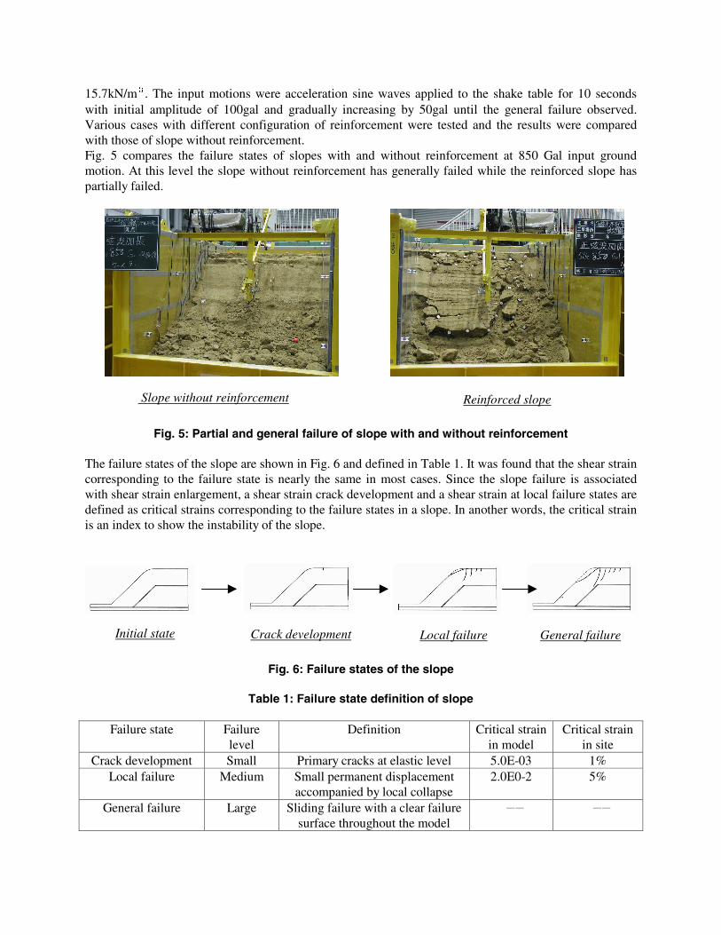
15.7kN/m3. The input motions were acceleration sine waves applied to the shake table for 10 seconds with initial amplitude of 100gal and gradually increasing by 50gal until the general failure observed. Various cases with different configuration of reinforcement were tested and the results were compared with those of slope without reinforcement. Fig. 5 compares the failure states of slopes with and without reinforcement at 850 Gal input ground motion. At this level the slope without reinforcement has generally failed while the reinforced slope has partially failed.
Fig. 5: Partial and general failure of slope with and without reinforcement
The failure states of the slope are shown in Fig. 6 and defined in Table 1. It was found that the shear strain corresponding to the failure state is nearly the same in most cases. Since the slope failure is associated with shear strain enlargement, a shear strain crack development and a shear strain at local failure states are defined as critical strains corresponding to the failure states in a slope. In another words, the critical strain is an index to show the instability of the slope.
Fig. 6: Failure states of the slope
Table 1: Failure state definition of slope
Failure state Failure
level Definition Critical strain
in model Critical strain
in site Crack development Small Primary cracks at elastic level 5.0E-03 1%
Local failure Medium Small permanent displacement accompanied by local collapse
2.0E0-2 5%
General failure Large Sliding failure with a clear failure surface throughout the model
- -
Initial state Crack development Local failure General failure
Slope without reinforcement Reinforced slope

The dynamic behavior and corresponding failure pattern of the slope at each stage are summarized below. - Initial stage: At initial stage with low seismic loading level, large deformation were not observed and no crack or failure were found. - Crack development: Increasing the acceleration level to the next stage, a primary crack developed in both models with and without reinforcement. - Local failure: At this level, the crest of the slope without reinforcement started to fail, while the reinforced model did not fail and remained stable. - General failure: At the final stage of seismic loading, the surface layer of the model without reinforcement entirely failed as a block. The reinforced slope, however, kept its shape while partially failed. The current reinforcement method prevented the slope from total collapse since the combination of rock bolts and rope net resist the slope deformation. Although the slope finally failed, it was observed that rope net would hold most of the loosened parts of the soil. Fig. 7 presents the measured displacement at crest of the slope and axial force of rock bolts.
Fig. 7: Acceleration vs. displacement and rock bolt axial force Reviewing the incremental behavior of the slope displacement, rock bolt axial force, and string tension of the rope net, shown in Fig. 7, the following conclusions can be made. - Slope displacement rapidly increases after crack development level. - Axial forces in rock bolts linearly increases until local failure level. - There is an increase in string axial tension force of rope net from crack development stage to local failure stage. As a result, it was found that reinforcement becomes more efficient as slope displacement increases. Authors developed a new idea based on displacement to judge the seismic stability of a slope, since displacement could be more reasonable than factor of safety to evaluate failures during large earthquakes.
0
5
10
15
0 200 400 600 800
Acceleration(gal)
Displacem
ent(m
m
)
0.00
0.01
0.02
0.03
0.04
0.05
0.06
0.07
0.08
0.09
0.10
Axial force(kN)
Displacem ent at the slope center
C rack initiation
Local failur
Axial force of a bolt
String tension of a rope

ESTABLISHMENT OF A DISPLACEMENT-BASED DESIGN METHOD Basic constitutive equation for estimating the shear strain of reinforced slope Based on shear deformation observed in slope models, authors developed a calculation method to estimate the shear strain of reinforced slope [1]. Fig. 8 shows the deformation of a soil block, surrounded by rock bolts and rope net, due to the seismic inertia force accompanied by a volumetric deformation with a Dilatancy angle of ν .
Fig. 8: Soil block and shear deformation The external virtual work of the system can be written in the combination of the work done by the seismic inertia force and the tensile force of the rope as
hAEBLhGW RBI22
2
1
2
1 εγ += (1)
The internal work of the system consisting of the work done by shear deformation of the soil block and the work done by normal strain in rock bolts are
hAEBLhGW RBI22
2
1
2
1 εγ += (2)
Equalizing the internal and external work of the system given in equations (1), (2) and solving for γ yields to the basic shear strain of reinforced slope as
( )0
84.tan4
4.tan4 223 =
−−⎥
⎦
⎤⎢⎣
⎡+++
RB
RNe
RB EA
TWk
EA
GBL γυγυγ (3)
in this equation,
BLhW e .γ= Weight of solid block
=eγ Density of soil
δ
TRN
γ
L
hy
dy dT
υ

=h Thickness of soil block (=length of rock bolt) =G Shear modulus of soil material =ek Acceleration in slope direction
=RNT Rope net axial force
=E Young modulus of rock bolt =RBA Cross sectional area of rock bolt
=υ Dilatancy angle In the absence of reinforcement, the basic equation for calculating the shear strain in slopes without reinforcement becomes
G
hk eeγγ = (4)
The stress-strain relationship of soil material can be considered linear only at very low stress levels. At relatively higher stress levels some microscopic cracks may occur accompanied by slippage between soil particles. This causes residual strain in soils and non-linear behavior of material. In the current calculation method, an iterative scheme is adopted to calculate the shear strain modulus based on equation (3) and the experimental stress-strain curve shown in Fig. 9.
Fig. 9: Stress-strain relationship obtained from cyclic triaxial test In this method, at each step, the initial modulus G0 is given and the initial shear strain is calculated using equation (3). A new shear modulus is obtained from the calculated shear strain and the experimental curve shown in Fig. 9. A new shear strain can be re-calculated using equation (3) and this iterative process
1E- 6 1 E- 5 1 E- 4 1E- 3 0.0 1
0 .0
0 .2
0 .4
0 .6
0 .8
1 .0
D at a: D at a3_G rat io
M odel : H ar r is
C h i^2 = 0.00016
G / G0=1/ (1+bγ
c
)
b 767 .99563
c 0 .76043
実 験 値
フィ ッ ト 曲 線
G/G
0
γ
ExperimenCurve fit

continues until the variation of the calculated shear strain converges. This process is repeated at each loading step and the shear modulus used in the computation is updated to match the non-linear behavior of the soil.
Fig. 10: Iterative scheme for stress-strain relationship of slope model Comparison with shake table test results In order to verify the efficiency of the new reinforcement method several shake table tests, with and without reinforcement, were conducted. Fig. 11 compares the calculated displacement and the axial forces of rock bolts and rope net with the values obtained from shake test. The calculated displacement results at low ground motions are in good agreement with experiment. At higher ground motions the experimental results become larger than the calculated one. However, the order of displacements for both methods, are still in agreement with each other. The axial forces of rock bolts and rope net for both methods matches and are acceptably close to each other. In general, based on the results obtained from shake table tests, it can be concluded that the results obtained from current method is accurate enough to estimate the shear deformation in reinforced slopes and to provide a basic tool to investigate the stability of slopes during earthquake. New design criteria to evaluate the stability of a slope Since shear strain closely associates with slope failure, it is consequently suggested that shear strain would be an alternative to the factor of safety combined with the conventional methodology to investigate and specify the unstable parts of a slope. The methods of soil investigation and evaluation of unstable parts are as following. - Soil investigation: As a basic method to investigate unstable parts in a slope, the handy penetration test is suitable in mountains since the equipment is portable and handy. The handy penetration test is a method to estimate soil consistency from the number (Nc) required to penetrate a standard cone of 10cm in depth from 50cm free falls of a hemmer with 5kgf weight. Okimura et al. [2] pointed out a number of failures observed in the layers with Nc less than 12 in Rokko Mountains. They called them collapsible layers. During the Hyogo earthquake most of the failures occurred in collapsible layers. Hence the handy penetration test could be a useful tool to locate the position of collapsible layers.

Fig. 11: Comparison between current calculation method and shake table test results Soil properties, strength and deformation for the design purpose are determined through laboratory tests on specimens taken from collapsible layers. Major necessary properties for design purpose and their importance are listed in Table 2.
Table 2: Properties for design and their importance
Test name Properties necessary for design Importance Density test Unit weight(γ ) ◎
Triaxial test Cohesion(C), internal friction angle(φ ) ◎
Borehole dilatometer Young modulus (E) ○ Down hope seismic Shear modulus(G0) ○ Cyclic triaxial test Strain dependant characteristic of shear
modulus(G/G0) ○
- Evaluation In order to specify the unstable parts in a slope, in the design method it is suggested to use the results of the multi-block stability analysis and results of the laboratory and handy penetration tests. In this analysis method, several blocks of slope are considered based on the topography and distribution of collapsible
0.0
1.0
2.0
3.0
4.0
5.0
6.0
7.0
8.0
9.0
10.0
0.0 0.2 0.4 0.6 0.8 1.0
Acceleration(g)
Displacement(mm)
0.000
0.005
0.010
0.015
0.020
0.025
0.030
0.035
0.040
0.045
0.050
Axial force(k
D isplacem ent (C urrent m ethod)
D isplacem ent (Experim ent)
Bolt axial force (C urrent m ethod)
Bolt axial force (Experim ent)
Rope net axial force (C urrent m ethod)
Rope net axial force (Experim ent)

layers and the factor of safety is calculated for each block. Among the calculated results, the minimum factor of safety represents the unstable part of the slope. In the next step, the reinforcement method is applied to the unstable parts and the displacement of the reinforced slope in an earthquake is estimated based on the design formula presented in previous section. To evaluate the stability of the reinforced slope, maximum allowable strains are determined considering the failure states observed in the shake tests and the importance of the objects in a slope failure as shown in Table 3.
Table 3: Maximum allowable strain
Importance of objects Failure state Critical strain Maximum limit High Crack development 1% Thickness of collapsible layer×1%
Ordinary Local failure 5% Thickness of collapsible layer×5% The stability of the reinforced slope is then evaluated based on the estimated displacement in a possible earthquake and the maximum allowable displacement defined for the slope. In this method, the maximum allowable strain is defined for the slope considering the importance of the objects and the failure state limit selected according to their value. In the case of strains more than allowable value, other reinforcement system should be substituted since the configuration of current reinforcement method is fixed. - Selecting the design earthquake In the design formula for calculating shear strain of reinforced slope, input ground motion is one of the important parameters that should be carefully selected based on the characteristics of an earthquake. Joyner & Boore [3] presented the attenuation equation (5) to estimate the maximum acceleration based on the magnitude of the active fault information and the distance of the site from active fault as, rrMA w 00255502490021 .log..)log( −−+−= (5)
Where 22 37.+= Dr and A is maximum acceleration (g), wM magnitude of earthquake, D is the horizontal distance of a site from epicenter in (Km). This equation gives the maximum value of the earthquake. In order to obtain the relationship between the peak acceleration of a real earthquake and sinusoidal wave, the shake table test gave the difference between the peaks of two waves. As shown in Table 5, this ratio varies from 0.56 to 0.62 depending on the failure state. It is assumed that the energy of a sinusoidal wave is equivalent to that of a static load. Referring to the concept of effective strain, which represents average strain in dynamic response, the ratio of 0.65 is taken for a conversion factor from the momentary peak to a static load. In order to consider the acceleration amplification due to the effects of topography and geological structure of the slope, 2D and 3D dynamic analyses were performed. Figure 12 shows the contour of acceleration in a 3D analysis model with 100.0m height. The amplitude of the acceleration at the top of the model is about 2.3 times of the base acceleration. Recurrent analysis is conducted for these response results with linear and 3rd order nonlinear polynomial approximation.
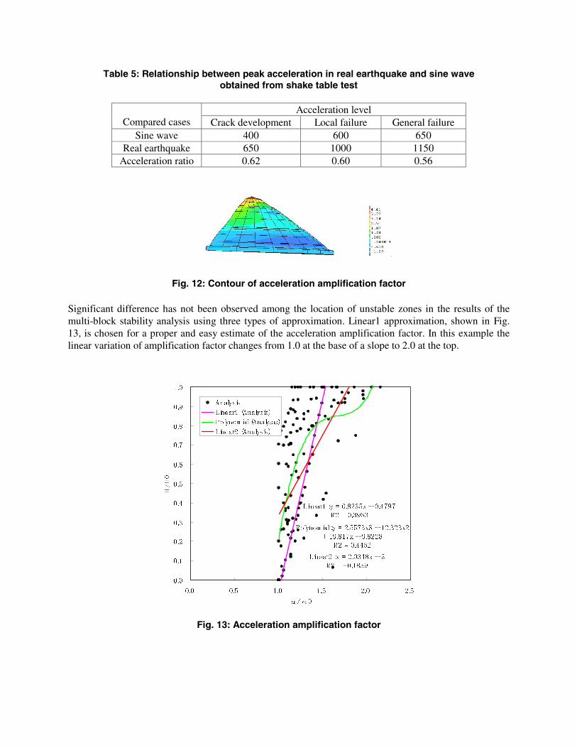
Table 5: Relationship between peak acceleration in real earthquake and sine wave obtained from shake table test
Acceleration level
Compared cases Crack development Local failure General failure Sine wave 400 600 650
Real earthquake 650 1000 1150 Acceleration ratio 0.62 0.60 0.56
Fig. 12: Contour of acceleration amplification factor Significant difference has not been observed among the location of unstable zones in the results of the multi-block stability analysis using three types of approximation. Linear1 approximation, shown in Fig. 13, is chosen for a proper and easy estimate of the acceleration amplification factor. In this example the linear variation of amplification factor changes from 1.0 at the base of a slope to 2.0 at the top.
Fig. 13: Acceleration amplification factor
Linear2:y = 2.0348x - 2
R2 = -0.1859
Polynom ial:y = 2.5573x3 - 12.323x2
+ 19.817x - 9.8228
R2 = 0.4452
Linear1:y = 0.8235x - 0.4797
R2 = 0.3953
0.0
0.1
0.2
0.3
0.4
0.5
0.6
0.7
0.8
0.9
1.0
0.0 0.5 1.0 1.5 2.0 2.5
α/α0
H
/H
0
Analysis
Linear1 (Analysis)
Polynom ial (Analysis)
Linear2 (Analysis)

CASE STUDY
Figures 14 and 15 show 2 slopes in a real site (named as case 1 and 2). Case 1 failed during an earthquake and the collapsed area is shown in Fig. 14. Case 2 was lightly damaged during earthquake but failed due to rainfall after earthquake (Fig. 15). Based on the multi-block analysis, the analytically collapsible areas are shown in the figures. The materials used for reinforcement are: rock bolts with young modulus of 2.0E08 KN/M2, diameter of 22.0mm, and rope net with 0.50x0.5m mesh size and 8mm diameter. The collapsible thickness of Case 1 and 2 are 2.7 and 0.62m respectively.
Fig. 14: collapsed area on case 1 Fig. 15: collapsed area on case 2
Fig. 16: Reinforced response of case 1 Fig. 17: Reinforced response of case 2 Figures 16 and 17 represent the response of the reinforced slopes. If the strain limit is set to 5%, case1 and 2 could withstand the maximum seismic ground motion of 0.25g and 1.15g, respectively. Since case1
0
50
100
150
200
250
300
350
400
450
500
0.0 0.2 0.4 0.6 0.8 1.0 1.2
Horizontal acceleration (g)
D
isplacem
ent(m
m
)
B
olt axial force(kN)
0.00
0.50
1.00
1.50
2.00
2.50
3.00
3.50
4.00
4.50
5.00
Rope net axial force(kN)
DisplacementBolt axi
Earthquake resistant limitRope axi
5% strain
0
5
10
15
20
25
30
35
40
45
50
0.0 0.2 0.4 0.6 0.8 1.0 1.2Horizontal acceleration (g)
D
isplacem
ent(m
m
)
B
olt axial force(kN
)
0.00
0.10
0.20
0.30
0.40
0.50
0.60
0.70
0.80
0.90
1.00
Rope net axial force(kN)
DisplacementBolt axi rEarthquake resistant limitRope axi
5% strain

failed during earthquake while case2 only received damage, the displacement curves show the difference between 2 cases and also to what extent the reinforced slopes would endure a possible earthquake.
SUMMARY A new reinforced method, including rock bolts and rope net, is developed to stabilize a natural slope during an earthquake. A design formula is introduced to estimate the shear strain of the reinforced slope based on principle of virtual work. The displacement calculated in this method is in good agreement with those obtained from shake table tests. To specify an unstable zone in a slope, the multi-block stability analysis is chosen. Design criteria, critical shear strain 1% and 5% are set for maximum allowable shear strain depending on the importance of the objects to be protected. The multi-block stability analysis is adopted to look for the unstable part of a slope to be reinforced. Estimating a seismic load is another important factor for design. Static design coefficient is derived using the attenuation equation, considering magnitude of the active fault, distance of the site from epicenter of active fault and the topographic amplification of the slope. In the case studies, the design procedure was examined. The results confirm the location of failure zones and the capability of the new reinforcement method. In conclusion, a displacement or shear strain can be a good index to show the dynamic behavior of a slope and the user can recognize the adoptability of the reinforcement method to each site and know to what extent the reinforcement is efficient.
ACKNOWLEDGEMENTS The authors gratefully acknowledge the member of advisory committee, Professor Okimura and Professor Tanaka in Kobe University, Professor Kusumi in Kansai University, Dr. Matsuura in Forestry and Forest Products Research Institute, Dr. Sugano in Port and Harbor Research Institute and Dr. Goto in National Disater Information Center for their expertise and valuable advises.
REFERENCES 1. H. Murakami, T. Kaneko, H. Kimura, S. Razavi Darbar. “A New Displacement based design
method for a new remedy of rope nets and rock bolts used to stabilize natural slopes” 3rd international conference in landslides, July 10-12, 2002, SINGAPORE
2. T. Okimura et al. “Research on Geological Structure and Failure Depth in Experimental Sites”, Journal of Japan Society of Erosion Control Engineering, JAPAN
3. W.B.Joyner and D.B.Boore, “Peak Horizontal Acceleration and Velocity from Strong Motion Records from the 1979 Imperial Valley, California, Earthquake” Bull. Seism. Soc. Am., Vol. 71, pp. 22011-2038, 1981, USA