new approach to multi-stage directional filter …altafrec/papers/2012_ims_2.pdfnew approach to...
TRANSCRIPT

New Approach to Multi-Stage Directional Filter Based on Band-Reject Filter Design
Jim S. Sun1, Humberto Lobato-Morales2, Alonso Corona-Chevaz2, Tatsuo Itoh1 1Electrical Engineering Department of UCLA
2Institute of Aerospace and Technology of Mexico
Abstract - A new structure for realizing multi-stage
directional filter is proposed in this paper. Instead of relying on one-stage directional filter as the building block, this approach relies on stand-alone band-reject filters. In this paper we investigate the viability of this idea by developing a three-stage directional filter prototype with elliptic response and 5.5% bandwidth. It is demonstrated that the final directional filter response is very close to the constituting band-reject filter, hence allows us to synthesize the directional filter with various kinds of responses in a more precise way based on the rich legacy from the filter community.
Index Terms - Directional filter, band-reject filter, elliptic function, multi-stage directional filter.
I. INTRODUCTION
Directional filter (DF) is a very useful component in wireless communication system for separating and combining channels [1], or in superheterodyne mixing to prevent unwanted reflection [2]. However, it has been difficult to realize a DF with response more than one-pole.
There are two main types of DF that have been popular, namely the traveling-wave loop type [3], and the strip-resonator type in Fig. 1(a) [4]. Until recently only the loop type DF could be successfully extended to multi-stage cases [5], [6]. However, this type of DF is difficult to build in practice, since the performance is very sensitive to any imperfection in the loop resonator. Hence, extensive tuning is needed, especially for filtering responses of more than two-pole type [5]. In recent years, investigation has been conducted on cascading two strip-resonator DFs in Fig. 1(a) together to achieve two-pole response [7], [8], [9]. Two transmission zeros appear at the two sides of the pass-band, which makes the cut-off rate sharper, and the response in the pass-band resembles maximally-flat function, which is flat rather than rounded as it is in the single-pole response. However, it seems that the ability to control the positions of the transmission zeros and the side-lobe level is very limited with this structure.
Here we investigate an alternative way to realize multi-stage DF based on the strip-resonator type structure. Instead of cascading two DFs, we cascade two identical differential band-reject filters (BRF). Since the response of the BRF can be specifically designed based on the rich research in the filter community [10], [11], this offers us an
alternative way to synthesize the DF response in a more precise way.
A DF prototype is developed in this paper to validate this approach. The DF is based on a BRF specifically designed with an elliptic response with -22dB matching and rejection ripples and 5.5% band-width centered at 1.5GHz. It is shown that the performance of the DF can be very closely predicted by the designed BRF, thus allows us to synthesize the DF with different responses more precisely.
II. CONCEPT OF MULTI-STAGE DIRECTIONAL FILTER STRUCTURE
In this section we describe the concept and the working mechanism of the DF structure proposed in this paper.
The basic strip-resonator type DF is shown in Fig. 1(a). It consists of two identical half-wavelength resonators coupled to the two main transmission lines (TL), and the 90o and 270o delay lines connecting in between. The coupled
Fig. 1 (a) One-pole strip-resonator type directional filter, and (b) the proposedmultiple-stage directional filter.
(a)
(b)
978-1-4673-1088-8/12/$31.00 ©2012 IEEE
half-wavelength resonator rejects the differential excitation between the two main TL at the resonance frequency fo, and passes the even excitation. The function of the 90o and 270o delay lines in the middle is to switch the excitation modes between the two main TL after the signal passes though it. Namely, switch to differential excitation when Port 1 and Port 4 are evenly excited, and vice versa. After doing the even and odd mode excitation analysis between Port 1 and Port 4, one obtains the conclusion that the response S41 is a single-pole band-pass response at fo, S21 is the band-reject response at fo complimentary to the S41 response, Port 3 is isolated from Port 1, and Port 1 is matched within a very wide band-width [9].
Since the half-wavelength resonator coupling into the main TL in Fig. 1(a) can be thought of as an one-stage BRF that is only excited under differential excitation, our attempt to the multi-stage DF design is to simply augment the single half-wavelength resonator to a multi-stage differential BRF. This proposed DF structure is shown in Fig. 1(b). The differential BRF used here should be designed so that it rejects differential excitation between the two main TL, and passes the even excitation, just like the half-wavelength resonator in Fig. 1(a) would. Since the underlying working mechanism of the DF just described is not disturbed, we should still obtain the directionality, but with higher-order filtering function.
In the following sections we describe the development of a three-stage elliptic function DF as the proof of concept.
III. ELLIPTIC BAND-REJECT FILTER
The core of the development of this DF prototype is the differential BRF. For the design of this BRF, we choose the natural prototype for elliptic function [10] since it allows the realization of the elliptic BRF without any complicated cross-coupling scheme.
The microstrip structure for this elliptic BRF is shown in Fig. 2. The design is based on elliptic function with -22dB ripple in both S11 and S21 with 5.5% band-width centered at 1.5GHz. We use the capacitively coupled step-impedance resonators to realize the three stages. The inter-digital capacitors are made of 0.5mm wide strips and 0.3mm gaps. The three resonators resonate at 1.535GHz, 1.5GHz and 1.465GHz respectively, and the normalized impedance slope
parameters (x/Zo) of the three resonators are 13.66, 7.6, and 13.04, respectively. Ideally, the delays between the resonators should be 102o and 79o, but the size of the inter-digital capacitors and their loading effect to the TL must be compensated [9]. So the delays between the resonators are shortened to about 44o and 24o. The resonators are only excited by the odd excitation between the two main transmission lines, so the even excitation is passed to the other end.
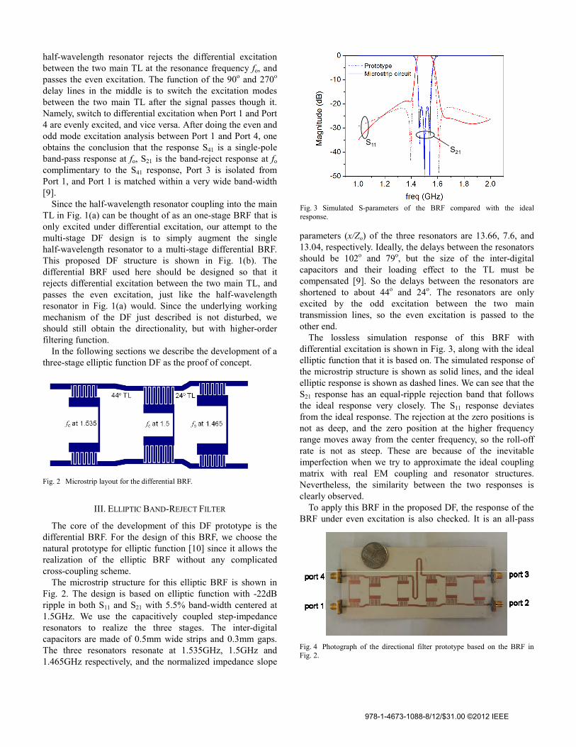
The lossless simulation response of this BRF with differential excitation is shown in Fig. 3, along with the ideal elliptic function that it is based on. The simulated response of the microstrip structure is shown as solid lines, and the ideal elliptic response is shown as dashed lines. We can see that the S21 response has an equal-ripple rejection band that follows the ideal response very closely. The S11 response deviates from the ideal response. The rejection at the zero positions is not as deep, and the zero position at the higher frequency range moves away from the center frequency, so the roll-off rate is not as steep. These are because of the inevitable imperfection when we try to approximate the ideal coupling matrix with real EM coupling and resonator structures. Nevertheless, the similarity between the two responses is clearly observed.
To apply this BRF in the proposed DF, the response of the BRF under even excitation is also checked. It is an all-pass
Fig. 2 Microstrip layout for the differential BRF.
Fig. 3 Simulated S-parameters of the BRF compared with the idealresponse.
Fig. 4 Photograph of the directional filter prototype based on the BRF in Fig. 2.
S11S21
978-1-4673-1088-8/12/$31.00 ©2012 IEEE

response in the frequency range of 0.5~2.5 GHz with matching level below -20dB, which satisfies the requirement to perform as a BRF in differential excitation and all-pass in even excitation.
IV. ELLIPTIC DIRECTIONAL FILTER PROTOTYPE
The 3-stage elliptic function DF is built by using the BRF introduced in Section III in the corresponding block in Fig. 1(b). The photograph of the realized DF is shown in Fig. 4. It is realized on Rogers RO3003 substrate with dielectric constant of 3 and thickness of 30 mil, and the size is about 14 cm long and 4.5 cm wide.
The simulated and measured responses are shown in Fig. 5 as dashed lines and solid lines respectively. Fig. 5(a) shows the S21 and S14 of the DF. The S21 response is a band-reject response centered around 1.5GHz, and there shows three rejection poles, which resembles the S21 response of the BRF in Fig. 3. The signal rejected by the S21 response is extracted to port 4. This is observed in the S41 response of the DF, which has a pass-band around 1.5GHz. Moreover, the S41 response resembles the S11 of the BRF in Fig. 3 closely, which has elliptic function characteristics. Further, there are two additional transmission zeros generated around 1.1 and
1.9 GHz in the S41 of the DF compared to the S11 of the BRF. This is due to the frequency dependence of the additional 180o phase delay in the upper main transmission line, and actually increases the rejection level in the stop-band.
Fig. 5(b) shows the S11 and S31 response of the DF prototype. We can observe that the structure is pretty well matched within the frequency range of 0.5~2.5GHz, and is below -12dB. Port 3 is isolated from Port 1. The S31 reaches -35dB at the center frequency of 1.5 GHz and levels around -17dB in the higher end of the frequency range.
V. CONCLUSION
In this paper we investigated a new methodology to the design of multi-stage DF. The DF connects two differential BRF together with proper delay lines. The prototype developed in this paper is based on the elliptic differential BRF with -22dB ripples and 5.5% band-width centered at 1.5GHz. With this prototype we verify that the band-pass and band-reject response of the resulting DF respectively resemble the S11 and S21 response of the constituting BRF. Based on the rich research in the filter synthesis, this allows us to synthesize multi-stage DF with different kinds of responses in a more precise manner.
VI. REFERENCE
[1] F. S. Coale, “Applications of directional filters for multiplexing systems,” IRE Trans., vol. 6, no. 4, pp. 450-453, October 1958.
[2] A. J. Catelino, “Directional filter for superheterodyne applications,” IEE Micro. Filters and Multiplexers Colloq., pp. 1-4, Nov. 1990.
[3] F. S. Coale, “A traveling-wave directional filter,” IRE Trans., vol. 4, no. 4, pp. 256-260, 1956.
[4] R. D. Wanselow, and L. P. Tuttle, “Practical design of strip-transmission-line half-wavelength resonator directional filters,” IRE Trans., vol. 7, no. 1, pp. 168-173, 1959.
[5] G. L. Matthaei, L. Young, and E. M. T. Jones, Microwave Filters, Impedance Matching Networks and Coupling Structures, New Tork: McGraw-Hill, 1964.
[6] Y. Cheng, W. Hong, and K. Wu, “Half-mode substrate integrated waveguide (HMSIW) directional filter,” IEEE Micowave and Wireless Components Letters, vol. 17, no. 7, pp. 504-506, 2007.
[7] S. R. Zinka, S. Nam, and J. P. Kim, “Multilayer directional filters with transmission zero characteristics,” Antenna and Propagation International Symposium, pp. 1-4, 2008.
[8] H. Lobato-Morales, A. Corona-Chavez, T. Itoh, and J. L. Olvera-Cervantes, “Dual-band multi-pole directional filter for microwave multiplexing applications,” Microwave and Wireless Component Letter, 2011, (viewable in IEEE Xplore).
[9] J. P. Kim, “Improved design of single-section and cascaded planar directional filters,” IEEE MTT-Trans., vol. 59, no. 9, pp. 2206-2213, Sep. 2011.
[10] J. D. Rhodes, “Waveguide bandstop elliptic function filters,” IEEE MTT-Trans., vol. 20, no. 11, pp. 715-718, Nov. 1972.
[11] R. J. Cameron, M. Yu, and Y. Wang, “Direct-coupled microwave filters with single and dual stopbands,” IEEE MTT Trans., vol. 53, no. 11, pp. 3288-3297, 2005.
(a)
(b) Fig. 5 Simulated and measured S-parameter of the directional filter in Fig.4.
S41
S21
S11
S31
978-1-4673-1088-8/12/$31.00 ©2012 IEEE