neutronic design on a small accelerator based li (p, n) neutron
TRANSCRIPT

1
Neutronic Design on a Small Accelerator based 7Li (p, n) Neutron Source for Neutron
Scattering Experiments
Fujio Hiraga, Takanori Okazaki and Yoshiaki KiyanagiHokkaido University
2010-08-16

2
Technical background• Small accelerator neutron sources with an intensity
more than 1012 s-1 are necessary to facilitate the application of cold neutron scattering experiments such as transmission measurements and small angle neutron scattering.
• A small proton linear accelerator with the proton energy of 2.5MeV has been put to practical use.
• The neutron intensity of 1012 s-1 is expected to be produced by a Li target and the small proton linear accelerator with the beam current of 1mA.

3
Neutronic advantages of the 7Li(p, n) source using 2.5 MeV protons
• The larger yield of neutrons than other methods with low energy protons around 3MeV.
• The smaller energies of neutrons (less than 800keV) than the evaporation neutrons.
• Higher efficiency for the neutron moderation at the 7Li source than a Bremsstrahlung (γ, n) source, and
• The decrease of the volume of the shield for neutrons around the sourceare expected.

4
The aim of this research• Examining the performance of models for the7Li (p, n) cold
neutron source.
• We study the neutronic performance using practical models where the neutron absorption in the structure materials and the neutron streaming in the channels around the moderator were taken into account, and make comparison of the performance with two different neutron production methods, 9Be(p, n) and Bremsstrahlung (γ, n).
• We next designed the shielding components for neutrons and γ- rays to reduce the volume and the weight of the shield around the source.

5
Part -1
The study on the neutronic performance, comparison of efficiency of neutron moderation
among three neutron production methods

6
Duct forprotons
Li target
Duct forneutrons
Moderator(22K CH4 )The length of methane in the direction of the initial protons : 2.5cm
Pre-moderator(polyethylene)
Reflector (Be)
Longitudinal section of the calculation model of the S-type cold neutron source
S-type: slab type

7
Duct forneutrons
Moderator(22K CH4 )The length of methane in the direction of the initial protons : 10cmLi target
Duct forprotons
Pre-moderator(polyethylene)
Reflector (Be)
Cross section of the calculation model of the L-type cold neutron source
L-type: lateral type

8
Li target :φ3×0.51
Cross section, unit:cm
Duct forprotons:6×6
Duct forneutrons:10×10
6
Pre-moderator(thickness: tp )
Moderator(thickness: tm )
Part of the reflector (thickness: tr )
Methane vessel(thickness: 0.5)
Thermal shield(thickness: 0.2)
Outer vessel(thickness: 0.6)
Detailed structure around the moderator for the L-type source
・The Li target: Li foil (t0.01) is installed on Cu can (t0.5).・We also examined the cases where the Li foil was replaced by the Be foil (9Be(p, n)) or the tungsten foil (Bremsstrahlung (γ, n) ).
9
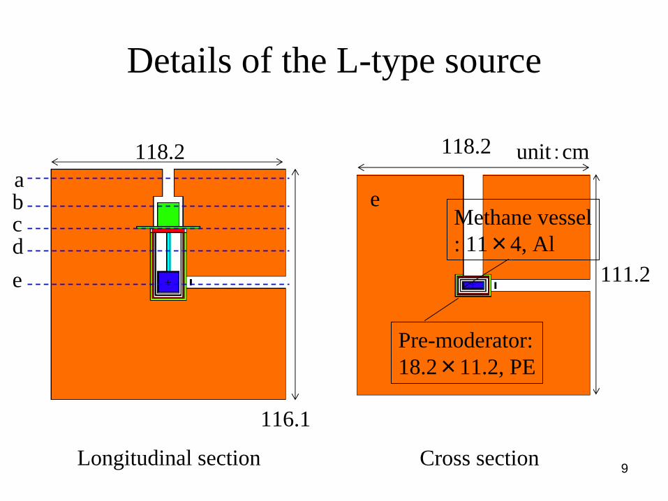
Details of the L-type source
Longitudinal section
abcde
Cross section
111.2
118.2
Channel: φ6×13.8
ab Channel:φ15×15
Refrigerator: φ11×12, Fe
c
Flange: φ32, Fe
d
Thermal shield: 13.2×6.2, Al
Outer vessel: 16.2×9.2, Al/Mg
116.1
118.2
e
Pre-moderator:18.2×11.2, PE
Methane vessel: 11×4, Al
unit:cm

10
10-10
10-9
10-8
10-7
10-6
10-5
0.0001
0.001 0.01 0.1 1 10 100
"7Li(p, n), Ep=2MeV""7Li(p, n), Ep=2.5MeV""9Be(p, n), Ep=11MeV""Brems (gamma, n), Ee=35MeV"
dY(E
)/dE
[1/c
m2 /M
eV/n
]
E [MeV]
Neutron energy spectra per produced neutron from various targets
The differential neutron yield:
7Li(p, n): C.L. Lee, X.-L. Zhou, LIYIELD,Nucl. Instr. Meth. B 152, 1 (1999)
9Be(p, n): S. Kamada, et al., Preprints 2006 Spring Meeting ofAt. Energy Soc. Jpn., K42, (2006)
(γ, n): J. F. Briesmeister (ed.),MCNPX, LA-12625, (1993)

11
Neutron angular distribution per produced neutron from various targets
0
1 10-5
2 10-5
3 10-5
4 10-5
5 10-5
6 10-5
7 10-5
8 10-5
0 50 100 150
"7Li(p, n), Ep=2MeV""7Li(p, n), Ep=2.5MeV""9Be(p, n), Ep=11MeV""Brems (gamma, n), Ee=35MeV"
dY(θ
)/dθ
[1/c
m2 /d
egre
e/n]
The direction of emission, θ[degree]

12
Type of source The moderator thickness [cm]
The pre-moderator thickness [cm]
The reflector thickness [cm]
7Li(p, n), Ep =2MeV S-type 2.5 1.5 40
L-type 3.0 1.0 507Li(p, n), Ep =2.5MeV S-type 2.5 1.5 40
L-type 3.0 1.0 509Be(p, n), Ep =11MeV S-type 2.5 1.5 50
L-type 2.5 1.0 50
Bremsstrahlung (γ, n), Ee =35MeV
S-type 2.5 1.0 50
L-type 2.5 1.0 60
Optimal dimensions of the moderator, pre- moderator and reflector for various cases of
cold neutron sourcesThe dimensions shown below were found by parametrical calculationsso that the intensity of cold neutrons (E<5meV) is maximized.

13
Comparison of neutron spectra per produced neutron between the S- and the L-type 7Li sources driven by
2.5MeV protons
The yield of neutrons from the Litarget peaks in the angle of 40 degree to the direction of the
initial protons and, moreover,
the configuration between the Li target and the methane
moderator for the L-type model differs from that of the S-type
model.
↓
The moderator of the L-type slows neutrons down more efficiently
than the S-type.
10-10
10-8
10-6
0.0001
0.01
1
10-10 10-8 10-6 0.0001 0.01 1
S-typeL-type6.063e-10/E
φ [
1/cm
2 /MeV
/n]
E [MeV]5 meV 0.5 eV

14
10-10
10-8
10-6
0.0001
0.01
1
10-10 10-8 10-6 0.0001 0.01 1
S-type 7LiL-type 7LiS-type evaporationL-type evaporation
φ [
1/cm
2 /MeV
/n]
E [MeV]
Comparison of neutron spectra per produced neutron between the 7Li and the Bremsstrahlung sources
A part of the high energy neutrons from the (γ, n) target passes
thorough the moderator. ↓
The intensity of cold neutrons with the energies less than 5meV for the
7Li sources are 1.4 timeslarger than that of the (γ, n) sources.
The difference in the angular distribution of neutrons between the
7Li and the (γ, n) targets. ↓
The difference in the inclination ofspectra above 0.5eV between the
7Li and the (γ, n) sources. 5 meV 0.5 eV

15
Type of source The fast neutron yield from the
target [1/s/mA]
The average energy of neutrons from the
target [MeV]
The cold neutron flux [1/cm2/nf ]
7Li(p, n), Ep =2MeV
1.10×10¹¹ 0.075 3.02×10⁻⁸
7Li(p, n), Ep =2.5MeV
8.80×10¹¹ 0.326 2.66×10⁻⁸
9Be(p, n), Ep =11MeV
2.15×10¹³ 2.04 2.07×10⁻⁸
Bremsstrahlung (γ, n),
Ee =35MeV
5.60×10¹³ 2.52 1.92×10⁻⁸
Fast neutron yield from the target, the average energy of neutrons from the target and the cold neutron flux per produced neutron for the L-type sources with various reactions

16
The calculation results show that• The 7Li source of 2.5KW (Ep =2.5MeV, I=1mA)
produces the intensity of cold neutrons of 2.34×10⁴
[1/cm2/s] at 5 m from the moderator, which corresponds to a typical Bremsstrahlung source of 0.77KW (Ee =35MeV, I=0.022mA).
• Higher efficiency for neutron moderation per beam power of the accelerator is obtained not by the 7Li source but by the Bremsstrahlung source; however, we have to study the shielding components around the source to achieve a compact neutron source.

17
Part-2
The design of the shielding components,comparison of the volume of the shield between
the 7Li source and the Bremsstrahlung source

18
The aim of designing the shielding components
• The reduction of the total surface dose of photons and neutrons on the shielding components down to 20 µSv/h,
since a 2.5 MeV proton linear accelerator having the surface radiation dose of less than 20 µSv/h on the shielding components is permitted to be used anywhere by the regulation in Japan.

19
Radiation sources used for the design of the shielding components
The Bremsstrahlung (γ, n) of 0.77KW (Ee = 35MeV, I = 0.022mA)Fast neutron yield: 1.23×10¹² s-1 (1.4 times larger than 7Li(p, n) of 2.5KW),Photon yield: 1.05×10¹⁶ s-1 (42,000 times larger than 7Li(p, γ) of 2.5KW), estimated by MCNPX.
7Li(p, n) of 2.5KW (Ep = 2.5MeV, I = 1mA)Fast neutron yield: 8.8×10¹¹ s-1, estimated by LIYIELD.
Reactions of photon production 7Li (p, nγ) 7Be 7Li (p, pγ) 7Li 7Li (p,αγ) 4He
Energy of photons [MeV] 0.429 0.478 14
Photon yield at the target [1/s]4.1×1010 † † 2.1×10¹¹ † 5.7×10⁶ ☆
†:
C.L. Lee, X.-L. Zhou, 1999,† † :A. Z. KISS et al, 1984, ☆:C. L. LEE et al, 2000.

20
Longitudinal section of the model for specifying the initial photon source that dominates the surface
photon dose of the 7Li cold neutron source
・We calculated the average spectrum of photons escaping from the surfaces of the reflector of the 7Li source of 2.5KW.
・We compared photons from the (n, γ) reactions in various components in the cold neutron source with those of the (p, γ) reactions in the lithium target.

21
Average spectrum of leakage photons from the (n, γ) reactions in various components in the L-type source and that of the (p, γ) reactions in the lithium target
1
10
100
1000
104
105
106
0.01 0.1 1 10
"(n,γ)""(p,γ)"
Phot
on fl
ux sp
ectru
m [1
/cm
2 /s]
E [MeV]
・The intensity of leakage photons is dominated not by the (p, γ) reactionsbut by the (n, γ) reactions.
・We adopted two layered shieldsconsisting of the inside boric acid resin slabs for neutrons and the outside lead slabs for photons to reduce the thickness of shields around the source.

22
Duct forneutrons
Duct forprotons
Reflector (Be)
Longitudinal section of the model for examining the thickness of the shield for neutrons around the
S-type source
・
The boric acid resin slabs (BAR) or the boron-enriched concrete slabs (BEC) are installed on the all surfaces of the reflector of the 7Li source of 2.5KWor the Bremsstrahlung source of 0.77KW.
・The neutron dose distributions on the slabs having various thickness were calculated.
Shield for neutrons (boric acid resin or boron-enriched concrete)

23
1
10
100
1000
20 30 40 50 60 70 80 90100 200
"Li(p, n), BAR""Li(p, n), BEC""Bremsstrahlung (γ, n), BAR""Bremsstrahlung (γ, n), BEC"
Max
imum
surf
ace
dose
[μSv
/h]
Thickness of neutron shield [cm]
Maximum neutron dose depending on the thickness of the slab
Abbreviation: BAR: boric acid resin, BEC: boron-enriched concrete
7Li of 2.5kW :36 cm thick BAR slab,50 cm thick BEC slab.
Bremsstrahlung of 0.77kW:140 cm thick BAR slab,150 cm thick BEC slab.
This is attributed to the neutrons with energies more than 800 keVemitted from the Bremsstrahlungtarget.

24
The necessary shielding components for neutrons around the 7Li source of 2.5MeV, 1mA
• The 36cm thick boric acid resin slabs (1.33g/cm3, H (4.71×1022 cm-3), B (9.04×1021 cm-3), etc.) : 6.7 tons weight
(89.8 tons for Bremsstrahlung of 35MeV, 0.022mA)
• The 50cm thick boron-enriched concrete slabs (2.2g/cm3, H (2.49×1022 cm-3), B (1.54×1021 cm-3), etc.) : 18.6 tons weight
(171.8 tons for Bremsstrahlung of 35MeV, 0.022mA)
• The use of the boric acid resin as a substitute for the boron-enriched concrete may make the construction cost for the shielding components decrease.

25
The 36 cm or 140 cm thick BAR slabs
Duct forprotons
Duct forneutrons
Reflector (Be)
Longitudinal section of the model for examining the thickness of the shield for γ-rays around the
S-type source
・The lead slabs or the iron slabs areinstalled on the 36 cm or 140 cmthick BAR slabs for the 7Li or theBremsstrahlung sources respectively.
・The photon dose distributions on the slabs having various thicknesswere calculated.
Shield for γ-rays (lead or iron )

26
Maximum photon dose depending on the thickness of the slab
7Li of 2.5KW:26 cm thick lead slab, 48 cm thick iron slab.
Bremsstrahlung of 0.77kW:36cm thick lead slab,70 cm thick iron slab.
This is caused by that the Bremsstrahlung source not onlyyields more photons but also containsthe more energetic photons than the 7Li source.
1
10
100
1000
20 30 40 50 60 70 80 90 100
"Li(p, n), Pb""Li(p, n), Fe""Bremsstrahlung (γ, n), Pb""Bremsstrahlung (γ, n), Fe"
Thickness of photon shield [cm]
Max
imum
surf
ace
dose
[μSv
/h]

27
The necessary shielding components for photons around the 7Li source of 2.5MeV, 1mA
• The 26cm thick lead slabs (11.35 g/cm3) :80.9 tons weight(492.3 tons for Bremsstrahlung of 35MeV, 0.022mA)
• The 48cm thick iron slabs (7.86 g/cm3) :126.9 tons weight (800.1 tons for Bremsstrahlung of 35MeV, 0.022mA)
• We should use the lead slab shields for the 7Li source of 2.5 KW from the weight point of view.

28
The calculation results show that
• The shielding components consisting of the inside boric acid resin slabs and the outside lead slabs are effective in dropping the weight and the volume of shields for the 7Li source of 2.5 KW.
• The 7Li source of 2.5 KW needs a much smaller volume of the shielding components than those of typical Bremsstrahlung sources of 0.77 KW.

29
Conclusion• The 7Li source of 2.5 KW allows flexibility for
installation in any facility with a low construction cost, since a 2.5MeV proton linear accelerator having the surface radiation dose of less than 20 µSv/h on the shielding components is permitted by the regulation in Japan to be used anywhere.

30
Calculations of the energy spectra and the angular distribution of neutrons from the target
• dY(E)/dE was estimated so that the target was placed in the center of a sphere with a radius of 100 cm and the neutron flux shape on the sphere per produced neutron was tallied by the MCNPX.
• dY(θ)/dθ was obtained by multiplying the neutron flux shape by 2πsinθterm from the solid angle differential element.