neutron imaging - paul scherrer institute · neutron imaging at the spallation ... industrial...
TRANSCRIPT

Neutron ImagingAt the spallation source SINQ
Information for potential users and customers

PSI in brief
The Paul Scherrer Institute (PSI) is a multi-disciplinary research centre for natural sciences and technology. PSI collaborates with national and international universities, other research institutions and industry in the areas of solid-state research and materials sciences, particle physics, life sciences, energy research and environmental research.
PSI concentrates on basic and applied research, particularly in those fields which are the leading edge of scientific knowlegde, but also contribute to the training of the next gen-eration and pave the way to sustainable devel-opment of society and economy. The Institute is actively involved in the transfer of new dis-coveries into industry, and offers, as an inter-national centre of competence, its services to external organisations.
PSI employs 1400 members of staff, making it the largest of the national research institu-tions – and the only one of its kind within Switzerland. It develops, builds and operates complex large-scale research facilities that impose particularly high requirements in terms of knowledge, experience and professionalism. PSI is one of the world’s leading user laborato-ries for the national and international scientific community.
ContactNIAG-Team:Dr. Eberhard H. LehmannTel.+41(0)563102963E-mail: [email protected]
NEUTRA Peter VontobelTel.+41(0)563103687E-mail: [email protected]
ICONDr. Anders KästnerTel. +41 (0)56 310 42 86E-mail: [email protected]
Industrial Applications:Dr. Christian GrünzweigTel. +41 (0)56 310 46 62E-mail: [email protected]
Communications Officer:Dagmar BarokeTel. +41 (0)56 310 29 16Fax +41 (0)56 310 27 17E-mail: [email protected]
Bro
sch
üre
Neu
tro
n Im
agin
g_N
utz
er_e
, 09.
2011
Picture: Luftwaffe Schweiz
Paul Scherrer Institut, 5232 Villigen PSI, Switzerland
tel. +41 (0)56 310 21 11, Fax +41 (0)56 310 21 99www.psi.ch, http://niag.web.psi.ch
Imprint
Concept/Editor
Neutron Imaging & Activation Group (NIAG)
Photography
NIAG, H.R. Bramaz
Layout
Irma Herzog, PSI
Druck und Fototechnik, PSI
Source details and specimen copy
requested for reprints.
Order from
Paul Scherrer Institut
Kommunikationsdienste
5232 Villigen PSI, Switzerland
Telephone +41 (0)56 310 42 61
Villigen PSI, June 2011
Battery research: distribu-
tion of the electrolyte
inside the battery,
visualized with neutrons.
Cover photo:
Placing a sample for radio-
graphic inspection at the cold
neutron imaging facility ICON.

Content
5 Neutron Imaging
5 Introduction 6 Nondestructive testing 7 Neutron transmission
11 Facilities
11 SINQ 12 NEUTRA Overview 14 ICON Overview 16 NEUTRA 17 ICON
19 Detectors & Methods
19 Principle of measurements 20 Detectors 22 Tomography 23 Time dependent neutron radio- and tomography 24 Energy-selective imaging 25 Phase contrast and dark-field microscopy with neutrons
27 Scientific use
31 Industrial applications
35 Outlook
35 Neutron imaging with polarized neutrons

The tomograph of a seashell describes exactly the 3 dimensional shell structure, allowing to extract
a numeric (wire frame) shell surface model.

This booklet presents information about “neu-tron imaging”, or as it is usually referred to, neutron radiography. Neutron radiography is in use at Paul Scherrer institute since 1997 and is still in further development, particularly with regard to new measurement methods and applications.
The following pages present information generally understandable by a broad audience, but targeted to potential users too. Fundamen-tals about neutron sources, area neutron detec-tors and the different measurement methods are explained. Selected results demonstrate the usefulness of neutron imaging for a wide range of applications.
Neutrons are – as their partners the protons – the building blocks of the atoms, of which matter is made. Free neutrons are produced solely by nuclear reactions. Besides their use for energy production in nuclear reactors, they are essential probes for materials research on atomic and molecular length scales. However they also can be used, like ordinary medical
X-rays, for radio graphy purposes on macro-scopic samples. In this booklet we concentrate on these latter, macroscopic, neutron imaging applications.
For neutron imaging, strong neutron sources are required in order to guarantee high quality radiography image. Paul Scherrer Institute oper-ated for many years the research nuclear reac-tor SAPHIR (commissioned 1957), which was replaced by the spallation neutron source SINQ in 1997.
Because high intensity neutron sources are not transportable, all neutron imaging investi-gations have to be performed on the site of the neutron source. The PSI spallation neutron source is driven by the large PSI proton accel-erator facility. Complementary to the neutron source, a large infrastructure allows investigat-ing selected samples, monitoring transport processes, or detecting structural material changes.
Neutron ImagingIntroduction
Photograph (right) and
transparent neutron
tomograph (left) of an old
camera. With neutron
tomography the inner
structure of the camera is
unveiled.
5

Nondestructive testing
Rendering an object transparent in order to directly detect cracks, hidden inner flaws or structural material changes is an engineer’s dream. Visible light, because reflected from or absorbed by the surface of most materials (except e.g. glass, water...), leaves us only with an opaque view of the object‘s outer surface. Nondestructive radiography technologies are used to detect material faults inaccessible to direct observation.
Nondestructive testing (NDT) methods are required if the functional capability has to be verified without object disassembly and/or if the sample integrity should not be affected by the investigation. Such methods are quite often mandatory, to guarantee the safe operation of a system or to check highly expensive or unique samples. NDT methods are therefore frequently applied in the aerospace and automobile indus-tries or in investigations of cultural artefacts.
Partial or full object transparency can be pro-vided by various physical modalities like X-ray, ultrasound, microwave, infrared radiation, etc. Since the discovery by Conrad Roentgen, X-ray is probably the best known radiation modality due to its widespread use in medicine and in industrial-scientific applications. The charac-teristics of the X-rays, i.e. wavelength and inten-sity, are chosen according to sample composi-tion and the aim of the investigation.
Like X-rays, neutrons penetrate matter. The Figure below shows the neutron radiography of a lock. Material composition and thickness yield different image contrasts, illuminating the individual components of the lock and detect-ing component flaws or possible assembly errors. Neutron imaging provides a complement to conventional X-ray investigations. Specific differences between the modalities are dis-cussed on page 9 of this brochure.
Neutron radiograph of
a steel lock, showing
individual metallic
components.
N E u T R O N I m A G I N G6

Neutron transmission
Neutrons act as probes for nondestructive test-ing because they can penetrate thick-walled samples. Due to the interactions of neutrons with matter, they provide an image of transmit-ted radiation i.e. a neutron radiograph. Since X-rays interact differently with matter, the two radiation modalities highlight complementary properties of an object‘s internal structure. A powerful neutron imaging facility requires a strong neutron source. The neutron beam should be well collimated and, to insure radia-tion safety, strongly shielded. For imaging purposes, neutrons are detected nowadays mainly using special area detectors, which provide digital images of high sensitivity and spatial resolution. Previously, X-ray films were used for this. Paul Scherrer Institut offers two state-of-the-art neutron imaging facilities, NEUTRA and ICON for thermal and cold neutron radiography, respectively. Several experimen-tal techniques are available for investigations in a wide range of scientific and industrial applications.
Neutron radiographyA radiograph is an image produced by radiation which passes through an object. Radiography is commonly known as the technique, providing radiographs on films or digital detectors, which relies on radiation transmission measurements. Medical X-ray is the application familiar to most people, due to its frequent use by physicians or dentists. In the hospital, X-ray computer tomography (CT), the three dimensional variant known for several decades, provides volumet-ric information about inner organs, bone frac-tures, cancer, … More and more, X-ray applica-tions spread into other scientific and technical fields, where they are tuned to special require-ments, e.g. sub micrometer resolution in syn-chrotron micro-tomography. Similarly, the use of ultrasound or nuclear magnetic resonance
techniques in science and industry is spread-ing. Neutron radiography however, although known a long time, is not yet widely used for nondestructive testing, because it is available only at a few places. Its complementarity to X-ray makes it an essential tool for NDT evalu-ations in cases for which ordinary X-ray fails e.g. transmission through heavy metal samples or detection of small amounts of hydrogen within a metallic base material. The principles of neutron and X-ray radiography measurements are the same, except for the different sources and interactions with matter of the radiation (see page 9).
The principle of a radiograph facility is shown in figure above. Neutrons are guided from the radiation source through an evacuated flight tube, the collimator, to the object. The neutron detector behind the sample first con-verts the transmitted radiation into another physical quantity, e.g. light, which is then meas-ured and recorded digitally. Each area detector element records the intensity of the neutron transmission in a pixel, an element of the image plane. The spatially varying neutron transmis-sion through the object is thereby mapped into
The principle of a neutron
radiographic facility. The
collimator selects a straight
neutron beam. A neutron area
detector behind the object
measures the transmitted beam.
N E u T R O N I m A G I N G 7

a plane radiography i.e. projection image. For tomographic neutron imaging, the sample has to be rotated in small angular steps around 180˚. Images of plane sections, perpendicular to the objects rotation axis, can then be math-ematically reconstructed from all projections and merged as a stack of slice images. Thus a volumetric, tomographic representation of its neutron attenuation characteristics is gener-ated (see page 22).
In reality a neutron imaging facility is more complex than sketched in figure on page 7. As mentioned above, a strong neutron source is an important prerequisite for high quality neu-tron imaging. For every radiation source, there are legal requirements regarding the safe oper-ation and radiation protection of the personnel. A neutron imaging facility is therefore located within a measuring room, constructed of thick concrete shielding walls, and accessible only through a labyrinth secured by a safety door (see pages 12 and 14).
Properties of the neutron…• Neutronsareneutralparticles(i.e.particles
without electric charge). Together with the positively charged protons, they are the building blocks of the atomic nucleus.
• Themassoftheneutronis1.67510-27 kg or 939.57 MeV/c2. (c representing the speed of
light, MeV is a physical energy unit. The two values relate to each other by Einstein’s famous formula E = mc2).
• Afreeneutronisnotstable,itisaradioactiveparticle. It decays after a mean lifetime of about 15 minutes into a proton, simultane-ously emitting an electron and an anti-neu-trino.
• Theinteractionofafreeneutronwithatomsis not influenced by their electron cloud. Therefore it can penetrate deeply into matter. The neutron reacts with the atomic nucleus in a manner which varies greatly with iso-topic composition and neutron energy. Some atomic nuclei, e.g. boron, lithium, cadmium, gadolinium, capture neutrons incident at low speed. This interaction process is termed neutron absorption. Materials containing such elements are well suited as shielding materials or for neutron detection. Other atomic nuclei, e.g. aluminium or lead, inter-act only weakly with neutrons; they are almost transparent for neutrons. Some nuclei induce rather a deviation of the neu-tron from a straight trajectory, producing neutron scattering reactions. Occurring in most isotopes, they are especially strong in hydrogenous materials.
• Like other elementary particles, neutronsact not only like massive particles but also like waves. The wave propagation formalism using the same laws of optics as applied to light(seephasecontrastonpage25and26),i.e. an index of refraction showing the effects of diffraction or interference, accurately describes some neutron interactions with matter.
• Aftertheircreationbyfissionorspallationreactions, free neutrons propagate at high speed. Their slowing down, termed neutron moderation, is determined by inelastic scat-tering processes with light elements e.g.
Comparison of
X-ray and thermal neutron
interaction probabilities
for selected elements.
1 5 6 8 22 26 28 82
Hydrogen Boron Carbon Oxygen Titanium Iron Nickel Lead
Atomic number
Neutrons
X-ray
N E u T R O N I m A G I N G8

hydrogen or deuterium in the moderator tank. For materials research, thermal or cold neutrons are of special relevance because their energy or wavelength is appropriate to elucidate the structure and dynamics of solid-state or soft matter. The dependence of the interaction probability of neutrons with matter on energy or wavelength can be used to produce variable image contrast in neutron radiography applications. Neutron detection reactions yield high probabilities at low neutron energies, a prerequisite for sufficient sensitivity and spatial resolution in neutron imaging.
… and differences with X-rayDiffering essentially from neutron radiation as described above, X-ray radiation is electromag-netic radiation which interacts with the elec-trons in the atomic shell of a nucleus. The atomic interaction probability correlates strongly with the number of electrons of an element, i.e. the atomic number Z. Heavy mate-rials induce strong X-ray attenuation, whereas light materials, like e.g. tissue, water, plastics … attenuate weakly. No such Z dependence exists for thermal or cold neutron matter inter-action. X-ray absorption (photoelectric effect) is the dominant reaction at low photon ener-gies, whereas X-ray scattering (Rayleigh-scat-tering and Compton-effect) prevails at higher energies. Figure on page 8 depicts the differing interaction probabilities of radiation with mat-ter for X-ray (yellow) and thermal neutrons (blue) for a range of materials from low Z (hydro-gen) to high Z (lead). The size of the circles indicates increasing interaction probability. The figure suggests that lead is an efficient shield-ing material for X-ray radiation, but not for neutrons, for which lead is almost transparent. An example is shown in the figure above: the neutron radiograph of a quite massive lead
container of unknown provenance. An empty plastic at its centre was easily identified by neu-tron radiography, since the hydrogen content of plastic material leads to strong neutron attenu-ation and thereby to a sufficient image con-trast. Thus, after neu-tron radiography, the lead container could be opened without risk to the personnel. Figure below presents comple-mentary images derived from X-ray and neutron radiography of a concrete sample embedded with steel fibres. The rendering of the neutron tomography volume in green shows clearly all components containing hydrogen e.g. cement, sand, but the embedded steel fibres are invis-ible. Displayed in blue, the X-ray CT of the same sample shows the embedded steel fibres. On the left in figure below, the X-ray and neutron radiograph of the concrete sample are shown in grey, illustrating that not as much detail about the sample composition can be derived from the ordinary radiographs as from three dimensional tomography.
Lead shielding container
made transparent by thermal
neutron radiography: side
view (left) and top view
(right). Inside,
a thin walled plastic can
becomes visible.
Transmission radiographs
(left) and tomographic views
(middle) made from a
concrete sample embedded
with steel fibres with X-ray
and neutrons.
9 cm13
.7 c
m
X-ray neutron X-ray neutron photograph
N E u T R O N I m A G I N G 9

Bird’s eye view of the spallation neutron source SINQ. The vertical proton beam impinges from below on
the heavily shielded target block in the middle. Neutron beams are extracted horizontally to several
instruments. The green area in the middle cover the NEuTRA imaging facility.
10 FA C I L I T I E S

To be used for neutron scattering or imaging, neutrons must be set free from the atomic nucleus. This can be achieved by nuclear reac-tions inducing fission or other types of nuclear transformation. The nucleus, or its fragments, reach thereby excited states, which de-excite by emission of secondary particles e.g. neu-trons and photons.
Nuclear fission and spallation are the two most important nuclear processes producing free neutrons. Nuclear fission is induced by the collision of thermal or fast neutrons with a neutron-rich, fissionable, heavy nucleus like uranium-235. There result, two radioactive, fission-product nuclei and 2–3 free neutrons. Under favourable conditions, one of the emitted free neutrons induces another fission reaction and sustains a chain reaction. This process drives nuclear reactors used for energy produc-tion or provides a neutron source for materials research. Most neutrons used for research purposes worldwide are generated by nuclear fission.
Nuclear spallation is induced by directing highly energetic charged particles, e.g. protons, onto metallic target nuclei. The charged parti-cles, produced by a particle accelerator at energies of several hundred MeV, collide with individual nucleons (i.e. neutrons or protons) of the target nucleus, which then are ejected or experience further collisions (intra nuclear cascade). This process yields a highly excited
residual nucleus, which de-excites by releasing further neutrons or protons (see figure below). Below energies of 15 MeV, no further nucleons are ejected and the residual is called a “spal-lation product” nucleus. This whole process, known as spallation reaction, may release 10–15 neutrons per incoming charged particle.
A spallation neutron source requires a pow-erful proton accelerator facility. The protons are confined and guided by magnets within evacu-ated tubes to the heavily shielded spallation neutron source (shown on page 10). The advan-tages of using a spallation source rather than a nuclear fission reactor are the much fewer nuclear safety concerns: no fissile material is needed, no chain reaction needs to be con-trolled, and less radioactive waste results. Neutrons generated either in a fission reactor or a spallation source are too energetic to be useful and must be slowed down by scattering processes to thermal energies (~2200 m/s) in a moderating medium, e.g. a heavy water tank. Cold neutrons are produced by scattering ther-mal neutrons on cold molecules e.g. liquid heavy hydrogen at –250 °C.
The spallation neutron source SINQ of Paul Scherrer Institute has been in operation since 1996(seefigurepage10).Thisbrochuregivesan overview of the two neutron imaging facili-ties NEUTRA (thermal neutrons) and ICON (cold neutrons), explaining available experimental methods and presenting selected neutron imag-ing applications.
FacilitiesSINQ
Neutrons produced by
spallation: high energy protons
hit a heavy atomic nucleus (e.g.
lead). The protons eject
nucleons from the target
nucleus, leaving a highly
excited residual, which yields
further nucleons.
11

12 FA C I L I T I E S
NeutrA
Position 3:radiography and tomography setup for large samples
13FA C I L I T I E S
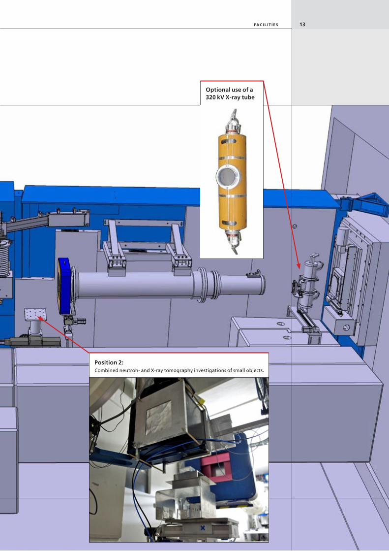
Position 2:Combined neutron- and X-ray tomography investigations of small objects.
Optional use of a 320 kV X-ray tube

14 FA C I L I T I E S
ICON
Position 3:Large and heavy objects, scanning.
Macro-tomography.
exit of flight tube, scintillation screen.
Neutron flight-tube

15FA C I L I T I E S
Position 1:Fail safe and experiment neutron shutter.
Options:
evacuated flight tube
Neutron velocity selector
time of flight chopper
Beryllium filter
Source grating for neutron interferometry
Position 2:Small objects
Micro tomography, scanning
Rotating drum with neutron apertures.

NEUTRA, the thermal neutron radiographic facil-ity, contains a convergent inner collimator tube section, guiding neutrons to a fixed size aper-ture 2 cm in diameter. From there, a divergent collimator section opens to a useful area of 15 cm diameter at the beam exit (measuring position 1) – 29 cm at position 2, and 40 cm at position 3. This permits neutron imaging of samples with dimensions ranging from a few cm to a maximum of 30 cm. Both radiography or neutron tomography experiments can be set up at the two measuring positions. The inves-tigation of highly radioactive samples is made possible by a special setup, NEURAP. In addi-tion, an X-ray tube may be positioned in the neutron beam path at position 1, thereby pro-viding almost identical imaging geometry for neutrons and X-rays, XTRA. Thus the comple-mentarity of X-ray and neutron attenuation may be fully exploited.
Highly radioactive objects are strong γ-sources, making nondestructive imaging by X-ray trans-mission impossible. However neutrons can be used for this purpose, if a special detector, sensitive only to neutrons, is employed. More-over, neutrons pass easily through the heavy metal components of nuclear power plants or neutron spallation sources. For radiation safety reasons, these samples must be transported and manipulated using shielding containers and remotely controlled equipment. The NEU-RAP setup, shown in figure below, permits positioning such samples in the neutron beam. Consisting of a heavily shielded steel cask with a built-in aluminium transport container which can be lowered into the radio graphy facility, it can be rotated about its vertical axis for tomog-raphy. Some results of investigation can be seen in the figure on page 30 (in the middle).
NEuRAP setup with shielding block (1) and trans -
port cask (2) containing the sample manipulator.
(1)
(2)
(1)
16 FA C I L I T I E S
NeutrA
(2)

The cold neutron imaging beamline, ICON, is a versatile beamline specialized on high resolu-tion and small samples. It has two experiment positions which are equipped with digital cam-era systems. Each position is equipped with motorized sample tables for exact sample posi-tioning and turn tables for tomography. The position closest to the source can use two different camera setups. They provide fields of view from 30 mm to 150 mm and pixel sizes from 13.5 μm to 150 μm. The other experimental position has a field of view of 300 mm and is more suited for large samples. The neutron aperture is variable in five steps from 1 mm to
80 mm, this can be used to balance the collima-tion ration versus the neutron intensity.
ICON provides equipment for advanced neu-tron imaging. An energy selector is mounted as a plug-in with short installation times. The selector can be used for material studies. Many materials have their major Bragg-edges in the cold spectrum. This material feature can be used to increase the image contrast of the sample. A setup for neutron grating interferom-etry is also available. This setup can be used for phase contrast and dark field imaging (see page25–26).
Comparison of NEUTRA and ICONThe flight tube of NEUTRA views the heavy water moderator tank at the position of maximal thermal neutron flux density. The end of the ICON flight tube inside the moderator tank is located near the cold source box, containing liquid heavy hydrogen at –250 °C. Distinct neutron wavelength spectra for the two facilities result, as shown in figure rigth, which induce different image contrasts.
The scattering of cold neutrons by thin layers of hydrogenous material is markedly enhanced relative to thermal neutrons, leading to greater hydrogen detection sensitivity. At longer neu-tron wavelengths, some materials show sharp edges in neutron interaction strengths. These Bragg edges are due to scattering phenomena of cold neutrons with the material’s lattice structure. Using neutron wavelength selectors, the Bragg edges may be used to enhance image contrast. More specific beamline characteristics are listed in table.
Comparison of NEuTRA with ICON.
0 1 2 3 4 5 6 7 8 9 100.0
0.2
0.4
0.6
0.8
1.0
wavelength [Å]
a. u
.
NEUTRAICON
1 Å = 10-10 m
NEUTRA ICONNeutron aperture D fix: ø 20 mm variable: ø 1 – 80 mmCollimation ratio L/D 200, 350 and 550 many steps: 90 – 12’000Neutron flux (n/cm2/s/mA) 7.5 106 5.8 106
(L = 7.1 m, D = 2 cm) γ filter, and filter for fast neutrons bismuth no filterTomography setup large samples additional micro-tomographyBeryllium filter none optionalNeutron energy selector none optionalCombined X-ray investigation XTRA noneHighly radioactive samples NEURAP weakly radioactive samples
Neutron wavelength
spectra of NEuTRA
(red) and ICON (blue).
17FA C I L I T I E S
ICON

18 m E T H O D S & D E T E C T O R S

Detectors & methodsPrinciple of measurements
Neutron detection is based mainly on the crea-tion of free electric charge carriers. Electrically neutral particles, i.e. neutrons produce such carriers by direct collisions with nuclei or neu-tron capture reactions that lead to the emission of charged particles (e.g. α-, β-particles, pro-tons, tritons, …). The most important elements for thermal or cold neutron detection exhibit very high neutron capture probabilities.
In a neutron imaging detector, the amount of electric charge produced by nuclear reactions is quite often not measured directly, but con-verted into another more observable physical entity such as light. In neutron scintillation screens, the charged particles stimulate light emission in zinc sulphide. The charged particles create electron-hole pairs which produce light when de-excited by laser stimulation via pho-tostimulated luminescence in neutron imaging plates known as storage phosphors. In X-ray films, the electromagnetic radiation produced by charged particles creates a latent image in the photoemulsion, which results in selective film blackening during chemical film-develop-ment.
In the past, neutron imaging relied exclu-sively on X-ray films, used together with a screen converting neutrons to X-rays or light. During the last several years, digital neutron detectors have gradually replaced the ana-logue, film-based detection schemes. The main advantages of digital systems are: chemical development is unnecessary, the digital images can easily be stored or copied and transferred quickly over long distances, and they can be post-processed. Additional important reasons favouring the use of digital detectors in neutron imaging are: the much reduced activation risk and the possibility of quantitative evaluation. Neutron irradiation of an object induces a – usually short-lived – activation. The shorter the
neutron exposure is, the smaller the induced activity. Digital neutron detectors are more sensitive than X-ray films by orders of magni-tude, permitting exposure times on the order of seconds rather than tens of minutes. In most cases the induced activity reaches safe levels within a few minutes. As described on pages 20 and 21, many digital neutron detection sys-tems covering a broad range of spatial- and time-resolution are available. They show a linear response over a wide range of neutron exposures permitting additional quantitative information about the shape/dimension or the composition of a sample under investigation to be derived. The requirements and aim of the investigation determine which system should be used. By their nature, digital images allow numerical processing. Statistical or systematic image distortions can be eliminated by meth-ods of digital image analysis e.g. noise filtering, contrast enhancement. Multiple images can easily be compared or transformed (e.g. divided) into new images. These methods are indispensable in analysing the images acquired with the elaborate techniques like tomography, time-resolved radiography or neutron phase imaging described in forthcoming sections.
19
Selected thermal neutron
detector materials and their
reactions.

Detectors
Neutron scintillation screen and CCD cameraThe cooled, light-sensitive CCD chip of the camera captures the light emitted from the neutron-sensitive scintillation screen. Opti-cal lenses fitted to the camera head capture variably sized fields-of-view from 4 to 40 cm. This detector is especially useful for neutron tomography.
Film based methodsX-ray films and special “track-etch foils” provide analogue images of high spatial resolution, but require long neutron exposures and film-development times.
CCD camera with light amplifierThe light intensity can be enhanced by an amplifier for very low light applications. The amplifier can be gated, i.e. trig-gered at exact time points, for short exposures, permitting in particular the analysis of fast, periodic movements.
20 D E T E C T O R S & m E T H O D S
Amorphous silicon flat panel detectorLight emitted from the neutron scintillation screen is captured by a narrow array of small photodiodes in direct contact with the screen. The diodes ac-cumulate charges, which can be read out at high frequency, permitting “real-time” neutron imaging.
10
1
0.1
0.01
0.0011.0E-04 1.0E-03 1.0E-02 1.0E-01 1.0E+00
exposure time [s]
spat
ial r
eso
luti
on
[m
m]
n-imagingplates
amorphous Si flat panel detector
slow scan CCD withscintillation screen
intensified CCD with scintillation screen

CMOS pixel detectorAn array of pixels collects the charg-es generated by neutron capture. Each pixel has its own amplifier and digital converter, permitting low-noise acquisition of multiple neu-tron events and fast detector read-out.
Imaging PlatesThese large-area, thin, plastic-like foils capture neutrons in a matrix containing gadolinium isotopes mixed with a barium, fluorine, euro-pium. Electron-hole pairs are generated, which, by laser irradiation, induce light emission. This pho-tostimulated lumines-cence can be recorded with high spatial resolu-tion using a laser scan-ning device.
Detector system Field of view Pixel size Dynamic Typical Read-out Read-out Special (typical) [mm] range exposure time time [s] rate prop. [greylevels] [s] [1/s]Film + converter 18 cm * 25 cm 0.02 100 approx. 1000 approx. 2000 not relevant Track-etch foil + B10 10 cm * 10 cm 0.02 100 approx. 2000 approx. 2000 not relevant CCD-camera + scintillator 25 cm * 25 cm 0.05–0.2 65536(16Bit) 1–90s 1–10s 0.1 – 0.5 intensified CCD + scintillator 25 cm * 25 cm 0.05–0.3 4096(12Bit) 0.001to1 1to5 0.1–0.5 triggern-sensitive imaging plate 20cm*40cm 0.05 65536(16Bit) approx.10 approx.300 notrelevant multipleuseamorph-Si flat panel 20 cm * 25 cm 0.127 4096(12Bit) 0.03to2 continuous 1to30Pixel-detector 3 cm * 8 cm 0.25 unlimited > 1 < 1
21D E T E C T O R S & m E T H O D S
1.0E+01 1.0E+02 1.0E+03 1.0E+04 1.0E+05
track etch foils withboron-10 converter
Gd converterwith X-ray film
CMOS pixel-detector

tomography
Tomography setup at position 3 of the NEuTRA radiographic facility.
Computed tomography is a method to acquire three dimensional information about the struc-ture inside a sample. The method applies to neutron as well as the more known X-ray imag-ing. It uses radiographic projection images from many views to reconstruct the distribution of materials in the sample. Mostly, the projections are acquired with equiangular steps over either 180°or360°tocoverthewholesample.Figurebelow shows an experiment setup used for neutron tomography. Here, the sample is rotated using a turntable in contrast to medical imaging where the beamline is rotated around the patient. The projection images are acquired using a combination of a scintillator to convert the neutrons to visible light and a CCD camera.
The transform of the projection data into a three dimensional image is a computationally intensive task handled by special reconstruc-tion software. During the reconstruction pro-cess, slices perpendicular to the rotation axis are produced. When these slices are stacked in a sequence they form a three-dimensional volume image of the sample.
The reconstructed volume data can be visu-alized using three-dimensional rendering graphics software. Using such tools, regions can be segmented based on their attenuation coefficients and geometry. This can be used to reveal the inside of the sample in three-dimen-sions as seen by the neutrons.
The 250 million year old skull of
the mammal-like reptile
Lystrosaurus. Top, a radiograph
of the skull reveals that the
structures provide sufficient
contrast for a tomography.
Bottom, a 3D rendering of the
CT-image with segmented
regions that show the restored
parts of the skull. The sample
was kindly provided by
Dr. R. Schoch, Staatliches
museum für Naturkunde
Stuttgart, Germany.
CT reconstructionProcessing time ~1 h
Data acquisition300–1200 projections Scan time 1–24 h
Data evaluationImage processing/analysis 3D VisualizationProcessing time hours or days
22 D E T E C T O R S & m E T H O D S

time dependent neutron radio- and tomography
Dynamic neutron radiography: running engine
Rapid periodic processes which can be found as an example in a running engine can be investigated by exact chronologically triggered exposures and therefore with short exposure times. The exposures of the identical cycle positions are summed up and merged into one image. This is shown as an example for a run-ning chain saw motor, running at idle speed with 3000 rpm. In total at 40 different crank-shaft positions neutron images of the interior ofthefullrotationof360degreewereacquired.The therewith obtained images can be put together to a movie. In this way the movie resembles a flip-book of the moving parts inside the motor. The current status of the measuring technology enables to take images with up 10000 rpm.
0° 90°
180°270°
Dynamic neutron radio-
graphy images of a running
two-stroke engine. The
images originate during idle
speed at 3000 rpm. Four
different crank shaft
positions out of 40 are
shown. The exposure time
for the triggered measure-
ment is 500 µs.
The corresponding movie
can be found:
http://neutra.web.psi.ch/
annual_reports.html.
23D E T E C T O R S & m E T H O D S
Setting up a real-time experiment (stroboscopic mode)
with a combustion engine driving a chain saw
(results below).

energy-selective imaging
Neutrons extracted from the NEUTRA or ICON flight tube have a wide range of velocities, or equivalently energy or wavelength. Images acquired with such polychromatic spectra are therefore energy averaged. Many polycristalline materials, notably metals, show steep steps in their neutron interaction probabilities at low
neutron energies. By means of energy selective imaging measurements, these Bragg edges can be used to enhance contrast or to elucidate changes in material properties. Narrow bands of neutron energies are selected by a spinning turbine wheel featuring lamellas which strongly absorb neutrons (see left figure). Only neutrons within a given velocity range pass through the wheel rotating at a selected frequency; the others are absorbed by the lamellas. Resulting wavelength spectra are shown in figure left.
Figure below displays the photograph (left) and three neutron images (right) of a thick steel weld acquired with three narrow energy spectra of most probable wavelength 3.4 Å, 4.0 Å and 4.4 Å. The inhomogeneity in the weld, visible differentially at the three energies , is due to variations in the crystal lattice properties of the material in the weld zone. Only energy-selective neutron radiography can reveal such changes.
Selecting a neutron energy range by a spinning turbine wheel set up in the
neutron flight path. The polychromatic spectrum is transformed into a narrow
energy band.
complete polychromatic
spectrum
selected narrow
energy band
24 D E T E C T O R S & m E T H O D S
Photograph (left) and three radiographs (right) of a thick steel weld taken with three narrow neutron energy bands at most probable
wavelengths 3.4 Å, 4.0 Å and 4.4 Å.

Phase contrast and dark-field microscopy with neutrons
Phase contrast and dark-field images with vis-ible light are indispensable tools for the mod-ern microscopy technology. PSI had succeeded to develop the corresponding imaging tech-niques for neutrons. Hereby quantum mechan-ical interaction of neutrons with matter can be made visible in two-dimensional and three-dimensional images.
Particle physicists consider neutrons as small particles; though due to wave-particle dualism neutrons can also be described by matter waves with a certain wavelength. Contrary to the con-ventional absorption contrast, where the con-trast differences arise from the different atten-uation of the materials, the image information in the phase contrast and dark-field images originate from a change in wavelength within the material.
In the case of the phase contrast method, one uses the fact that the waves which trans-verse an object have a different velocity to those which do not, and therefore have a different wavelength. The resulting displacement of the wave maxima leads to a change of the propaga-tion direction and therefore to an angular change. An example from classical geometrical optics clarifies how a phase sensitive image can be obtained. By considering a beam path through a collection lens, it follows from the law of refraction that initially parallel light rays are refracted towards the optical axis. In a wave-optical description this corresponds to a lens induced angular change of the light rays, and namely a spatially dependent phase shift of the wave front.
In order to obtain phase contrast imaging, we measure the local angular variation of the neutron beam caused by the object. The exper-imental difficulty is therefore to measure effi-ciently, for a variety of image points, such small diffraction angles, in the range of 10-4 degrees.
Therefore one uses two grids (G1 and G2) which are composed of lines with lattice constants of a few micrometers. Such a grating is shown in Figure on this side above. The gratings together with a spatially resolving neutron detector then form the so-called neutron grating interferom-eter, as depicted in the Figure below. The local angular change can be determined by pixel wise analysis of the measured intensity.
Measurements of the phase shift of neutrons in interferometry experiments have been used so far to experimentally verify quantum mechan-ical predictions. The work at PSI aims to com-bine the available information about the phase shift with a space-resolved imaging technique, in order to image the quantum mechanical interaction of neutrons with matter and to offer new contrast possibilities.
One of the gratings with fine
lines in the micrometer range
manufactured at PSI as used
in the neutrons grating
interferometer. The wafer
has a diameter of 100 mm.
The grid area is 64 x 64 mm2.
The rainbow is caused by the
refraction of light at the fine
structures of the grating.
Illustration showing the
setup of the neutron grating
interferometer, consisting of
a phase and an absorption
grating and an imaging
detector. With the help of
this setup neutrons can be
detected, which have been
deflected or scattered at an
angle of 10-4 degrees.
25D E T E C T O R S & m E T H O D S

Figure below shows the results obtained for test samples. The conventional neutron absorp-tion image (left) shows no measurable differ-ence in the attenuation behaviour of the two metals, Copper and Titanium. The image of the measured phase shift (right), however, clearly shows a difference. Particularly interesting is the opposite sign of the phase shift of Copper (black in the image against the gray back-ground) and Titanium (white to gray); this is a consequence of the different signs of the refrac-tive indices of the materials.
For the dark-field imaging method the scat-tering properties of the interior of the materials is considered, resulting in Neutrons being scat-
tered during their passage through the material; the passage through the material consists of interactions with materials of different refractive indices, resulting in a small angle change. This method can be used, for example, to visualize magnetic domains in ferromagnetic materials, as shown in Figure below. Neutrons are de- flect ed due to the interaction of the neutron spin with the local magnetic fields, since mag-netic domains with different orientations have different refractive indices. Therefore, neutrons are scattered in the transition from one domain to the next at the domain walls, seen in the dark-field image as white lines.
measured neutron images of a
magnetic sample (Silicon Iron)
in the form of a disk with a
thickness of 300 microns and
a 10 mm diameter.
Left: Conventional absorption
image; Right: Dark-field image.
The white lines which form a
rhombus are magnetic domain
walls.
measured neutron images of
two metallic rods with a 6 mm
diameter and made of Copper
and Titanium. (Left) Conven-
tional absorption image;
(right) phase contrast image.
26 D E T E C T O R S & m E T H O D S

Scientific use
Research into wood and soil: e.g. precise analyses of moisture
content in wood samples
Hydrology and geology: e.g. analyses of rock formation
or geological transport
processes
Nuclear technology: e.g. examination of fuel
elements and quality control
Archaeology and museum research: e.g. research into
bronze and iron objects or
paintings
Palaeontology: e.g. examination of fossils
materials research: e.g. investigations of alloys,
welds, etc.
Neutron Imaging
Wood- and soil-physics (Hydro-) geology
Nuclear technology
Archaeology and cultural heritagePalaeontology
Materials research
27

Soil structure and humidity transportDue to its high sensitivity to small amounts of hydrogenous compounds in a matrix, neutron radiography and tomography can be used to measure humidity transport in soil. The meas-urements are needed for the validation of simulation models used to analyze the mobility of nutrients, pesticides, contaminants … in soil. Typically, radiographic time series of repre-sentative soil agglomerates, as shown in fig-ure below, are used to quantify water transport. Volumetric tomography measurements can be acquired of quasi-stationary states.
Renaissance bronzesRenaissance bronzes from the Rijksmuseum Amsterdam were investigated by neutron tomo-graphy in order to study their casting. Old bronzes usually have a quite high lead content, which make them ideal candidates for nonde-structive analysis by neutron tomography. From
the tomographic volume, virtual slices can be generated, revealing the inside of the bronze as figure below shows. The shape and size of bronze hollows or additional filling materials yield conclusions about the casting process. Resins or varnish used for the conservation of sculptures appear with high contrast.
Tomographic views of a bronze sculpture: virtual slices and transparent views can be created without damaging this unique object.
Photo: rijksmuseum Amsterdam
Humidity transport in small
soil agglomerates (diameter
5 mm) as recorded by
radiographic snapshots taken
over several hours. The
moisture alone is revealed by
dividing the radiograph of the
wet state by the radiograph
of the initial dry state.
28 S C I E N T I F I C u S E
t=0 1 min. 10 min. 2 Std. 4 Std. 8 Std.
Humidity exchange rate
influenced by area of wet
surface

Fuel cell investigationsIn comparison to combustion engines, fuel cells are attractive, because they allow for a highly efficient conversion of chemical energy stored in a fuel into electricity. A major application of fuel cells is in the automotive industry, where they are considered as promising alternatives to the internal combustion engine. The charac-terisation and optimization of the physico-chemical processes taking place within the device are a main objective of fuel cell research and development, worldwide.
The electrochemical reaction of hydrogen with oxygen in a fuel cell produces water, an essential aspect of fuel cell operation. Neutrons can monitor water distribution within a working fuel cell non-invasively, because they penetrate the exterior holding plates easily and yield radiographs with sufficient spatial and time resolution. Used simultaneously with other advanced, spatially-resolved characterization methods of the cells‘ electrochemistry, neutron radiography provides important insight into fuel cell operation.
The changing water content
of the fuel cell membrane
affects fuel cell behavior.
Performance characteristics,
i.e. current density and cell
resistance, of a PEm fuel cell
are shown as a function of
channel length.
The increase of the moisture
content inside the fuel cell
at different the power
densities is clearly visible and
quantifiable by neutron
imaging techniques.
2
A ir
1 3 4 5 7 9
anode end plate
neutron radiographcathode flowstructure
segmented current collectors
6
100
250
0
30
60
wat
er c
onte
nt [m
l/m2 ]
R Ω
[m
Wcm
2 ]
1 5 10 segment
cath de e t collectors
r .h (H 2 /air) = 80%
T Cell = 70 °C
Mittlere Stromdichte i = 0.5 A/cm 2
1 5 10 300
600
segment
i [m
A/cm
2 ]
te
I Cell = 100A
de low lectors
r h = 80%
29S C I E N T I F I C u S E
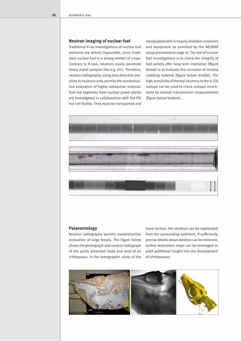
PalaeontologyNeutron radiography permits nondestructive evaluation of large fossils. The Figure below shows the photograph and neutron radiograph of the partly dissected head and neck of an ichthyosaur. In the tomographic study of the
head section, the skeleton can be segmented from the surrounding sediment. If sufficiently precise details about skeleton can be retrieved, further restoration steps can be envisaged to yield additional insight into the development of ichthyosaurs.
Neutron imaging of nuclear fuelTraditional X-ray investigations of nuclear fuel elements are almost impossible, since irradi-ated nuclear fuel is a strong emitter of γ-rays. Contrary to X-rays, neutrons easily penetrate heavy metal samples like e.g. UO2. Therefore, neutron radiography, using area detectors sen-sitive to neutrons only, permits the nondestruc-tive evaluation of highly radioactive material. Fuel rod segments from nuclear power plants are investigated in collaboration with the PSI hot cell facility. They must be transported and
manipulated with in heavily shielded containers and equipment as provided by the NEURAP setuppresentedonpage16.Theaimofnuclearfuel investigations is to check the integrity of fuel pellets after long term irradiation (figure below) or to evaluate the corrosion of zircaloy cladding material (figure below middle). The high sensitivity of thermal neutrons to the U-235 isotope can be used to check isotopic enrich-ment by neutron transmission measurements (figure below bottom).
Radiographic inspection of
nuclear power plant fuel rod
segments: single fuel pellets
show fractures and chips
(top), zirconium hydride
lenses due to cladding
corrosion (middle), or fresh
fuel pellets with varying
isotopic enrichment (lower).
Fossilised skeleton of an
ichthyosaur partially dissected
by u. Oberli, St Gallen.
Photograph (left), radiograph
(middle), and tomographic
view of head section (right).
30 S C I E N T I F I C u S E

Industrial applications
Welding, soldering & brazing: quality assurance and
tightness, integrity
Adhesive connections: glue
distribution, in particular behind
thick metal layers
Fuel cell performance: water
production rate and local
distribution
Structural integrity and performance: observation for
cracks, corrosion after operation
Two-phase flow: water
detection in metal pipes, time
dependent, e.g. refrigerator
Combustion engines: real
time studies of running devices,
Diesel particular filter perfor-
mance
Neutron Imaging
Combustion engines
Welding, solderingand brazing
Adhesive connections
Fuel cell propertiesStructural integrityand performance
Two-phase flow
31

Industrial ApplicationsNeutron Imaging is in use as a tool for non-destructive and non-invasive inspection of industrial components. The higher standards in safety issues, the permanent improvement of material properties and more complex struc-tures in industrial systems require more sophis-ticated techniques for diagnostics.
Here, neutron imaging fits in as a comple-mentary option in respect to the well-known X-ray techniques which are also under progres-
sive improvement. The example in figure on the right of an actuator shows impressively the difference in the image results of the two meth-ods – neutron and X-ray inspection. Whereas neutrons better identify plastics and sealing materials, the X-rays show metallic components while “ignoring” organic materials more or less.
Neutron imaging techniques can favorably be applied when larger metallic components have to be transmitted and small amounts of hydrogenous materials have to be visualized.
Study of a casted Al part from car industry where some shrinkage cavities filled with casting remains can be identified with the help of neutron tomography (left: the outer shape of the object; middle, right: semi-transpa-rent metal with the holes in colour).
Adhesive connection of a metallic car component (photo left) where neutron tomogra-phy allows a separation of the glue (red colored) from the metallic structure; the inhomogeneous distribution becomes obvious and might limit the solidity of the structure.
32 I N D u S T R I A L A P P L I C AT I O N S
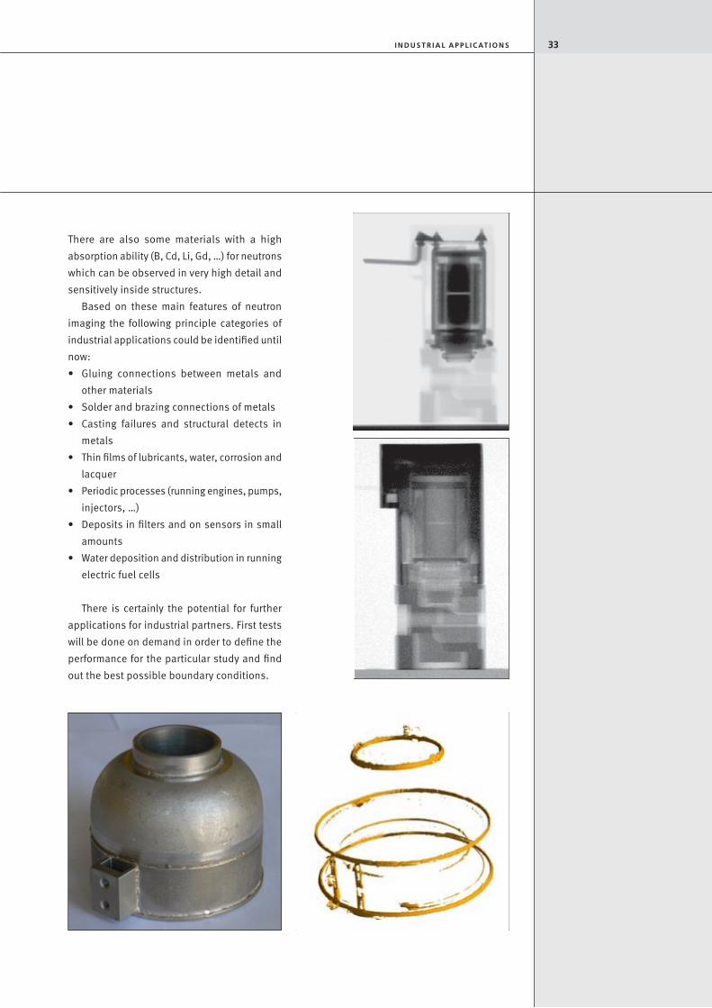
There are also some materials with a high absorption ability (B, Cd, Li, Gd, …) for neutrons which can be observed in very high detail and sensitively inside structures.
Based on these main features of neutron imaging the following principle categories of industrial applications could be identified until now:• Gluing connections between metals and
other materials• Solderandbrazingconnectionsofmetals• Casting failures and structural detects in
metals• Thinfilmsoflubricants,water,corrosionand
lacquer• Periodicprocesses(runningengines,pumps,
injectors, …)• Depositsinfiltersandonsensorsinsmall
amounts• Waterdepositionanddistributioninrunning
electric fuel cells
There is certainly the potential for further applications for industrial partners. First tests will be done on demand in order to define the performance for the particular study and find out the best possible boundary conditions.
X-ray (above) and neutron images (below) of an encapsulated initiator device showing complementary information about the inner structure and performance. While the X-rays show the metallic structures through the plastic cover in very detail, the organic materials (sealing rings, plastics, adhesives) becomes better visible with neutrons than the metal. In particular the fit and condition of the O-ring was highly relevant for the customer.
A non-invasive inspection tool for boron containing soldering connections is found in neutron imaging. A destructive inspection is not required when neutron tomography is applied to the object on the left. By suitable software tools the metal can be separated from the solder distribution show on the right.
33I N D u S T R I A L A P P L I C AT I O N S

A petrol station filler nozzle is prepared for investigation at the ICON neutron radiography
facility. The radiograph is shown on the right.
34 S C I E N T I F I C u S E

OutlookNeutron Imaging with polarized neutrons
It is well known that neutrons as elementary particles obey a spin which occurs in two states (up/down). A neutron beam extracted from a source contains both states in the same amount,
Polarized neutrons with only one spin state can only be obtained if the other state is sorted out by means of different filter options which absorb and suppress 50 % of all neutrons.
Neutrons also carry a magnetic moment which follows the spin orientation. In this way, neutrons can be considered to be small micro-scopic magnets. They can be arranged in a magnetic field and precise around the direction of the field.
This property of the polarized neutrons ena-bles to visualize directly magnetic structures, the distribution of magnetic fields and effects of magnetization in different materials.
For this purpose, a setup is needed as shown in Figure: after their polarization the neutrons hit the area with the magnetic relevant structure where a variation of the distribution of the polarized neutrons happens. This influence of the magnetic effects onto the distribution of the polarized neutrons can be measured by means of a neutron sensitive imaging detector arranged behind the analyzer of the polarized neutrons.
The principle of this kind of measurements has already been demonstrated [1]. At PSI we intend to establish and to improve the method by using the BOA beam line which already delivers a highly intense polarized beam in order to improve the spatial resolution and to reduce the acquisition time in the measure-ments. New magnetic materials and magnetic phenomena should be investigated and visual-ized on the macroscopic level.
Reference:
[1] N. Kardjilov et al., Nature Phys. 4 399-403 (2008)
Principle setup of experiments
with polarized neutrons for the
study and visualization of
magnetic phenomena
Visualization of the distribu-
tion of the magnetic field
around a magnet levitated
above a superconducting
sample of YBa2Cu3O7. This
measurement was done at the
CONRAD facility of the
Helmholtz Centre Berlin [1].
35