networked futures || new network architectures
TRANSCRIPT
New Network Architectures
DEFINING AN ARCHITECTURE
Architecture is primarily about how function (a place to live, a place of worship, a way of conveying speech over long distances) is repre- sented in a consistent overall form rather than as a listing of its detailed components - the bricks, the windows, the electromechanical relays. But it is nevertheless determined to a significant degree by the characteristics of these basic materials: a church built of wood is unlikely to have exactly the overall form of one built of brick, just as a telephone network based on radio links is unlikely to mirror exactly one that uses optical fibre.
There are always considerable arguments about what constitutes an architecture, even whether the term is a legitimate one to use for anything other than real buildings but if we simply use it as a way of making it easier to understand the most significant features of the net- works and their attachments, emphasising difficulties and require- ments to meet changing circumstances, then we can justify its use.
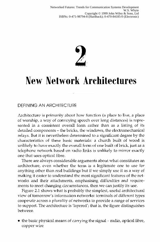
Figure 2.1 shows what is probably the simplest, useful architectural view of tomorrow’s information networks: terminals of different types cooperate across a plurality of networks to provide a range of services to support. The architecture is ’layered’; that is, the figure distinguishes between
0 the basic physical means of carrying the signal - radio, optical fibre, copper wire
Networked Futures: Trends for Communication Systems DevelopmentW.S. Whyte
Copyright © 1999 John Wiley & Sons, LtdISBNs: 0-471-98794-8 (Hardback); 0-470-84185-0 (Electronic)
NEW NETWORK ARCHITECTURES /I -1
Figure 2.1 A simple architecture for information networks
0 the way the connection is controlled, independent of the physical means - for example, is there something equivalent to a setting-up period preceding something like a telephone 'call' followed by a closing-down procedure?
0 the services - making a computer and a telephone interoperate, for example
0 the innumerable applications that run on top of all the above.
There are other architectural diagrams that use more or fewer levels, define them rather differently or even use extra dimensions at each layer. Architectural models are useful, conceptually, but seldom are real systems defined from a purely architectural viewpoint. In the discussions that follow, we necessarily jump between layers in the architecture - usually without warning - and that is why we have chosen what might be considered to be a lowest common denomin- ator that can be conveniently retained at the back of the mind.
INTEGRATION
The greatest challenge facing the coming generations of networks is that of integration: integration of the old legacy with the new, and integration of the locally optimum solutions for radio, computing, telephony and consumer electronics, because we wish our networks to carry out an integration of services (Figure 2.2):
1. We want to provide a truly global service 2. for people on the fixed (wired) network

30 NETWORKED FUTURES
3. 4. 5. 6. 7.
8. 9.
10. 11.
Figure 2.2 Integration of services
to talk to each other and people on the move with personal communicators, including mobile workstations/personal computers and those on a fixed network, and to allow computers to pass information to each other and to humans, and to involve entertainment and other consumer products, and also to enable many to communicate to many in a rich multimedia environment security and reliably at economic cost,
THE HISTORICAL LEGACIES
If the networks of the next decade are to meet the potential markets for communication of information and entertainment, providing them globally and on the moire, with rich multimedia environments, there will have to be some major changes in the ’network architecture’. Today, there are two competing architectural viewpoints, that of telecommunications and that of computer networks. Neither alone is sufficient and both will have to evolve to meet their individual needs. These needs will converge, and we shall explore how this con- vergence may come about, both by fairly orderly evolution and by the revolution brought about by the explosion of bandwidth made available by optical fibre. First, we need to look at the architectural heritage.
NEW NETWORK ARCHITECTURES 31
TELEPHONY TRANSMISSION ARCHITECTURE - THE ‘TAPERED STAR‘
Telephony naturally developed a centralised architecture as soon as it became desirable to connect a large range of people by means of individual pairs of wires (the only technological option at the time). If A wishes to connect to any of n people, then YZ possible connections are required; if B now wants to connect to any of the other, (n - 1) further connections are required (one less because B is already connected to A). For all the n customers to be connected to each other requires IZ + (n - 1) + ( n - 2) . . . + 2. -t 1 total connections; that is, a number of the order of n2. If all telephones in Great Britain were to be connected together by a dedicated pair f wires, we should require about one billion pairs of wires going into our houses. Thus, early on, it became obvious that the system could work only if the individual wires were taken to a central point, a telephone ’exchange’, where they could be selectively connected when required.
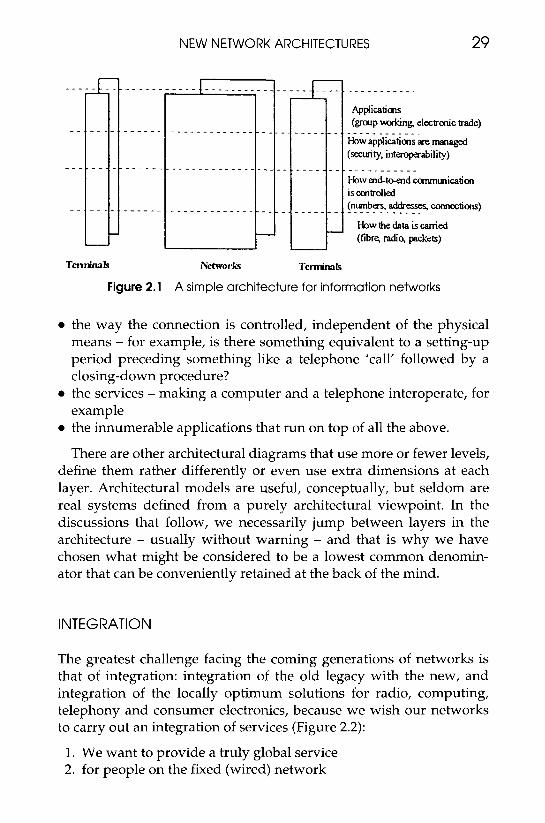
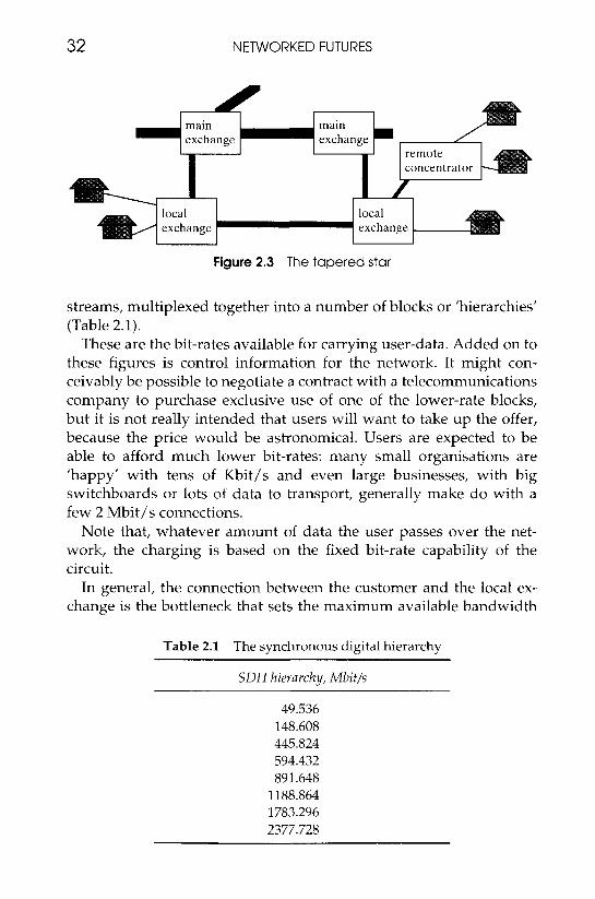
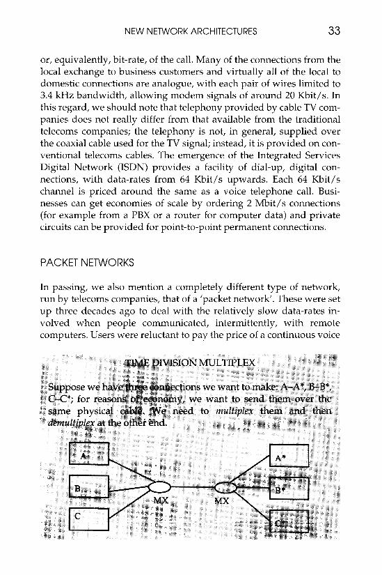
Reducing the number of direct connection points from several million customers to several thousand telephone exchanges meant that more money could be spent on each individual inter-exchange route. The cables could be ’better’, in terms of resistance to electrical noise or by having lower attenuation of the signal per mile. Most significantly, by deploying coaxial cable and modulation schemes such as time division multiplex (see frame, page 33), several hundred separate telephone calls could be carried on one cable. The telephone network therefore resembles a ‘tapered star’: each individual cus- tomer is provided with one pair of wires (per telephone ’line’) making the connection to the local exchange or, in some cases, a simpler ’remote concentrator’; at the local exchange or concentrator all the customers’ connections are electronically multiplexed onto the better, inter-exchange cables; long-distance calls may be switched onto even higher-capacity circuits that run between main exchanges (Figure 2.3).
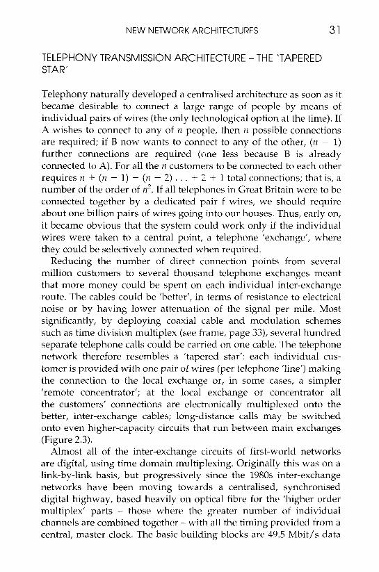
Almost all of the inter-exchange circuits of first-world networks are digital, using time domain multiplexing. Originally this was on a link-by-link basis, but progressively since the 1980s inter-exchange networks have been moving towards a centralised, synchronised digital highway, based heavily on optical fibre for the ’higher order multiplex’ parts - those where the greater number of individual channels are combined together - with all the timing provided from a central, master clock. The basic building blocks are 49.5 Mbit/s data
32 NETWORKED FUTURES
U
Figure 2.3 The tapered star
streams, multiplexed together into a number of blocks or 'hierarchies' (Table 2.1).
These are the bit-rates available for carrying user-data. Added on to these figures is control information for the network. It might con- ceivably be possible to negotiate a contract with a telecommunications company to purchase exclusive use of one of the lower-rate blocks, but it is not really intended that users will want to take up the offer, because the price would be astronomical. Users are expected to be able to afford much lower bit-rates: many small organisations are 'happy' with tens of Kbit/s and even large businesses, with big switchboards or lots of data to transport, generally make do with a few 2 Mbit/s connections.
Note that, whatever amount of data the user passes over the net- work, the charging is based on the fixed bit-rate capability of the circuit.
In general, the connection between the customer and the local ex- change is the bottleneck that sets the maximum available bandwidth
Table 2.1 The synchronous digital hierarchy
SDH hierarchy, Mbitls
49.536 148.608 445.824 594.432 891.648
1188.864 1783.296 2377.728
NEW NETWORK ARCHITECTURES 33
or, equivalently, bit-rate, of the call. Many of the connections from the local exchange to business customers and virtually all of the local to domestic connections are analogue, with each pair of wires limited to 3.4 kHz bandwidth, allowing modem signals of around 20 Kbit/s. In this regard, we should note that telephony provided by cable TV com- panies does not really differ from that available from the traditional telecoms companies; the telephony is not, in general, supplied over the coaxial cable used for the TV signal; instead, it is provided on con- ventional telecoms cables. The emergence of the Integrated Services Digital Network (ISDN) provides a facility of dial-up, digital con- nections, with data-rates from 64 Kbit/s upwards. Each 64 Kbit/s channel is priced around the same a s a voice telephone call. Busi- nesses can get economies of scale by ordering 2 Mbit/s connections (for example from a PBX or a router for computer data) and private circuits can be provided for point-to-point permanent connections.
PACKET NETWORKS
In passing, we also mention a completely different type of network, run by telecoms companies, that of a 'packet network'. These were set up three decades ago to deal with the relatively slow data-rates in- volved when people communicated, intermittently, with remote computers. Users were reluctant to pay the price of a continuous voice
34 NETWORKED FUTURES
connection and, as an alternative, they were offered a network which passed blocks of data ('packets') through a series of relays that stored data and then passed it on through network connections that were completely separate from the 'normal' telephone network. By storing the data and delaying it until a path was free, it was possible to make the system cheaper than a voice network - and the delay also ensured that it could not be used as a way of bypassing the telephone network! The service specification promised delivery of the packet in the correct order, with minimal chance of losing a packet, but without a tight specification on network delay. Charging could be based, at least in part, on the number of bits transmitted, rather than on 'call
NEW NETWORK ARCHITECTURES 35
duration’. Although packet switching never remained close to the centre of mainstream telecommunications thinking over its first 30 years, it promises to have great significance for the next, as we shall see in later sections.
TELEPHONY CALL CONTROL ARCHITECTURE - CENTRAL INTELLIGENCE
As well as transmitting calls across the network, it is necessary to route them between the correct points. Just as with the transmission architecture, call control follows a centralised model.
In the early days of telephony, when the telephone handset was lifted, a switch was closed resulting in a lamp lighting at the operator’s position. The operator then asked the caller for the number wanted and worked out the best way to switch the call across the network (Figure 2.4).
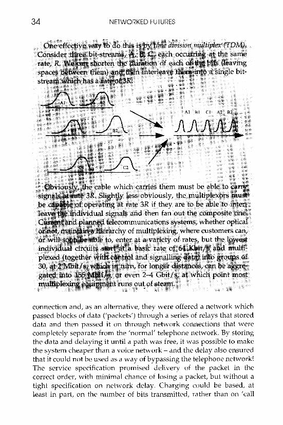
Figure 2.4 Manual operator switching
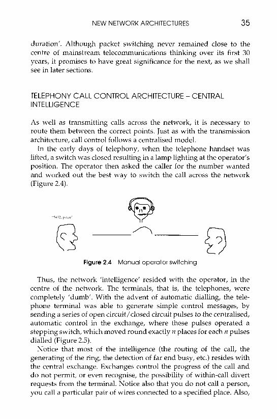
Thus, the network ’intelligence’ resided with the operator, in the centre of the network. The terminals, that is, the telephones, were completely ’dumb’. With the advent of automatic dialling, the tele- phone terminal was able to generate simple control messages, by sending a series of open circuit/closed circuit pulses to the centralised, automatic control in the exchange, where these pulses operated a stepping switch, which moved round exactly n places for each n pulses dialled (Figure 2.5).
Notice that most of the intelligence (the routing of the call, the generating of the ring, the detection of far end busy, etc.) resides with the central exchange. Exchanges control the progress of the call and do not permit, or even recognise, the possibility of within-call divert requests from the terminal. Notice also that you do not call a person, you call a particular pair of wires connected to a specified place. Also,
36 NETWORKED FUTURES
Figure 2.5 Automatic call routing
the connection is completely end-to-end and symmetrical, from a telephone to a telephone, with the expectation that two-way traffic will take place, with similar characteristics in both directions. Finally, during the call, the network is as transparent as possible, providing a fixed width (in terms of signal bandwidth), with minimum end-to-end delay. This is achieved by the operator, or the automatic equipment, establishing a guaranteed end-to-end route.
EVOLUTION OF TELEPHONY ARCHITECTURE - 1960s TO PRESENT DAY
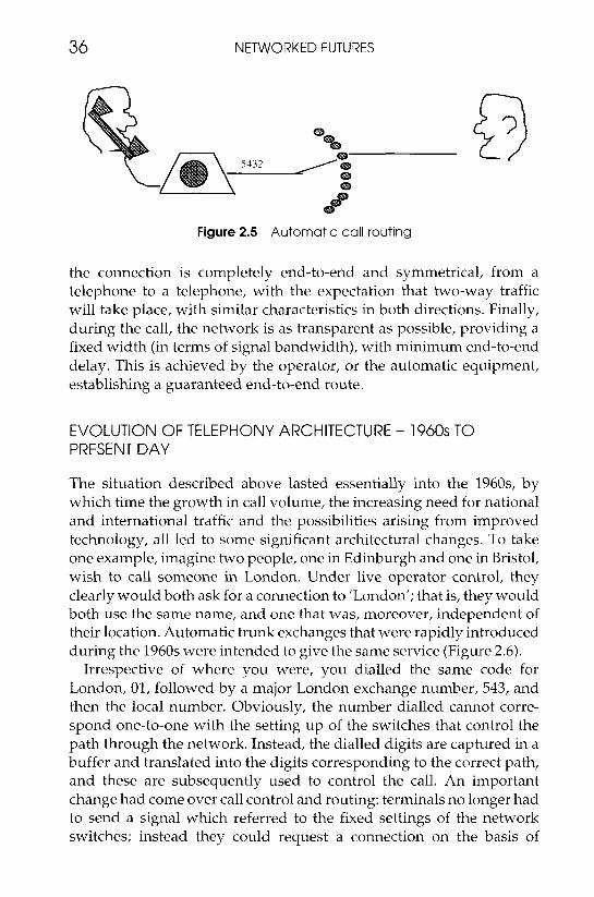
The situation described above lasted essentially into the 1960s, by which time the growth in call volume, the increasing need for national and international traffic and the possibilities arising from improved technology, all led to some significant architectural changes. To take one example, imagine two people, one in Edinburgh and one in Bristol, wish to call someone in London. Under live operator control, they clearly would both ask for a connection to 'London'; that is, they would both use the same name, and one that was, moreover, independent of their location. Automatic trunk exchanges that were rapidly introduced during the 1960s were intended to give the same service (Figure 2.6).
Irrespective of where you were, you dialled the same code for London, 01, followed by a major London exchange number, 543, and then the local number. Obviously, the number dialled cannot corre- spond one-to-one with the setting up of the switches that control the path through the network. Instead, the dialled digits are captured in a buffer and translated into the digits corresponding to the correct path, and these are subsequently used to control the call. An important change had come over call control and routing: terminals no longer had to send a signal which referred to the fixed settings of the network switches; instead they could request a connection on the basis of

NEW NETWORK ARCHITECTURES 37
‘01 543 6789’ London
Figure 2.6 Automatic trunk dialling
supplying a number which bore no fixed relation to the switch pattern. This ’call by name’ principle, as opposed to ’call by value’, to borrow a term in computer terminology, has quite important ramifications. One case is that of ’personal numbering’: you can be given a number which refers to you, rather than to the telephone line running into your house. Provided you have some way of indicating to the network that you have moved to another location, then the number dialled can, in principle, be translated to your new location. This is exactly what is done in the case of mobile networks, which maintain continually updated databases of the location of mobile terminals; see the selection on cellular networks for more details. The flexibility of number translation was an early example of software control, and the exchange switching equipment that deployed it was an example of a special- purpose computer. From the beginning of the 1970s there has been an ever-increasing interest in the introduction of computer processing into switching systems, in order to provide a cost-effective and flexible ’intelligent network’. The telecoms companies have had, until perhaps recently, a fairly well-defined and focused view of what they meant by an ’intelligent network’. Why there had recently been a partial loss of nerve we shall discuss later, but let us first look at their original vision.
INTELLIGENT NETWORKS: THE ‘TELECOMS VIEW’
The intention was that the intelligent network of the future was still to be predominantly a narrowband, voice network catering for telephony
38 NETWORKED FUTURES
rather than data or multimedia. Because the network was intelligent and built to respond to standardised commands, it would be possible to give a very wide, potentially global set of services offering maximum flexibility to customers (see frame).
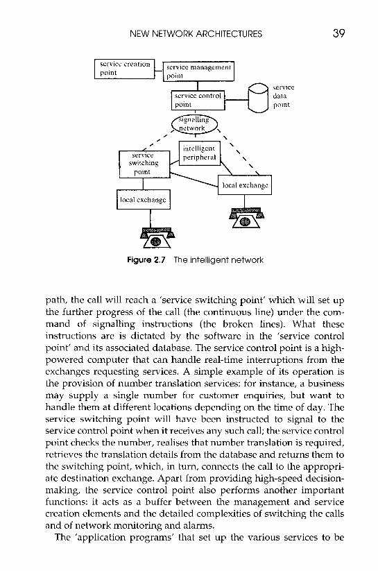
The technology to deliver these services is outlined in Figure 2.7. In this design, telephones are still connected to 'local exchanges', some of which will still be 'unintelligent'. However, at some point in the
NEW NETWORK ARCHITECTURES 39
service control - I point I 6 data service
point
, service
switching peripheral
point
local exc
1 local exchange I hange I
I
Figure 2.7 The intelligent network
path, the call will reach a 'service switching point' which will set up the further progress of the call (the continuous line) under the com- mand of signalling instructions (the broken lines). What these instructions are is dictated by the software in the 'service control point' and its associated database. The service control point is a high- powered computer that can handle real-time interruptions from the exchanges requesting services. A simple example of its operation is the provision of number translation services: for instance, a business may supply a single number for customer enquiries, but want to handle them at different locations depending on the time of day. The service switching point will have been instructed to signal to the service control point when it receives any such call; the service control point checks the number, realises that number translation is required, retrieves the translation details from the database and returns them to the switching point, which, in turn, connects the call to the appropri- ate destination exchange. Apart from providing high-speed decision- making, the service control point also performs another important functions: it acts as a buffer between the management and service creation elements and the detailed complexities of switching the calls and of network monitoring and alarms.
The 'application programs' that set up the various services to be
40 NETWORKED FUTURES
performed are written on the computers used for service management and service creation, in high-level scripts that do not require detailed understanding of the switching, etc. For example, we could imagine a programme called ’time of day routing’, which simply requested the business customer to complete a table of destination addresses against times of day.
Also shown in the diagram is the ’intelligent peripheral’. Callers and called parties can be connected to such a device, if it were, for example, providing a network answering service. A service could be created that, after normal business hours, switched all calls to the recording machine. In the morning, the business could call into the answering machine and retrieve the calls.
The intelligent network is a major departure from traditional telephony in a number of ways:
0 It replaces calls to fixed numbers by calls to flexible ‘names’. 0 It treats calls in two parts; in particular, a caller can be connected to
an intermediate platform such as an intelligent peripheral. 0 It allows flexible configuration of the network, to deliver a range of
customised services.
Nevertheless, events may have put into doubt some of the earlier certainties of the intelligent network. For instance, it is now realised that networks of the future may have much greater demands for bandwidth and for more complex services. Multimedia terminals are a case in point. The intelligent network will have to be expanded to cope with the flexible switching of circuits with data rates of several megabits, perhaps within an ATM ’packet’ network, rather than one consisting of fixed, switched circuits.
But perhaps the biggest impact on the intelligent network may come from the growth in the use of networked computers. We need to look at the parallel developments in the computing industry. We shall find a very different view and a set of attitudes which are in sharp contrast to the opinions held by telecoms professionals (see frame).
THE EVOLUTION OF COMPUTER NETWORKS
Initially, computing networks shared some of the centralised approaches so characteristic of telephone networks. The big computer sat at the centre of the system and access to it was either by physical
NEW NETWORK ARCHITECTURES 41
media (cards, tape) batch-loaded in a quiet period, or through dumb terminals. Notice, however, that the connection was never sym- metrical: it was from a terminal to a different type of device, usually a big machine which may have been serving a number of terminals; also, the terminals could not demand attention whenever they wanted it: the centre polled the terminals according to its own time-plan.
Many of the applications that were developed were not time-critical, at least within a second or so. Payroll and billing systems were early examples and, as performance improved, database query systems, for example on customer help desks, became widespread. Database sizes increased and, for performance and reliability reasons, it became necessary for these large machines to communicate with remote databases over private wires. Programmers and other users of these machines discovered that the networks thus set up provided a convenient means for sending electronic messages: e-mail was born.
The emergence of the low-cost workstation in the 1970s caused a major shift in the architecture of computer systems. ’Client-server’ working replaced the centralised, big-box model where most of the intelligence and control resided at the centre, with one where the terminals could request centralised service, such as access control, electronic mailbox management, storage and communication services, etc., from the central machine, but themselves possessed significant processing power and the ability to run applications locally. The network that connected the terminals and the servers was ’local’, usually to a building or campus. The data flowing between the terminals and between them and any central service was high speed, but ‘bursty’. Because the distances were short, the data-rate capacity of the connecting cable was not usually an issue, and there was no
42 NETWORKED FUTURES
intelligent clients and st'rvc'l-s
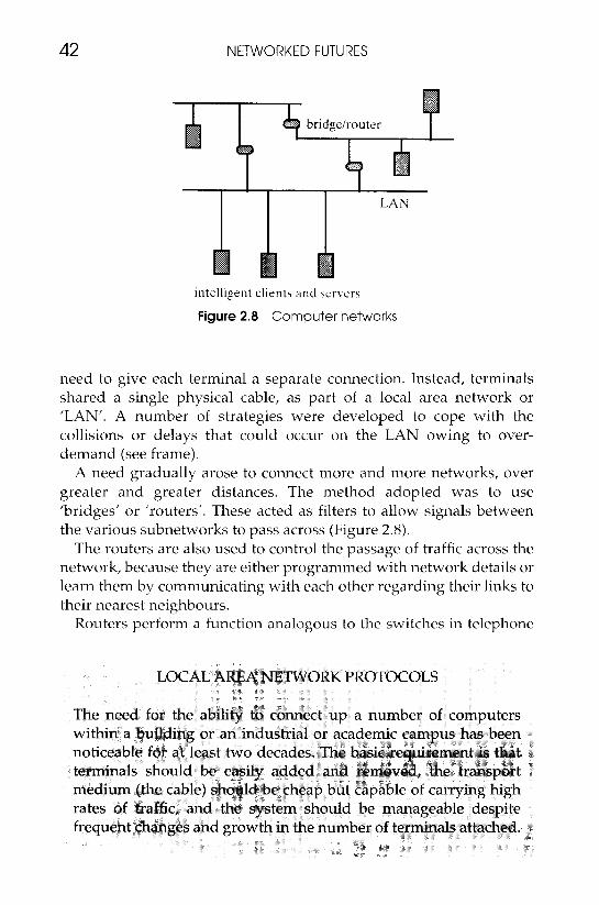
Figure 2.8 Computer networks
need to give each terminal a separate connection. Instead, terminals shared a single physical cable, as part of a local area network or 'LAN'. A number of strategies were developed to cope with the collisions or delays that could occur on the LAN owing to over- demand (see frame).
A need gradually arose to connect more and more networks, over greater and greater distances. The method adopted was to use 'bridges' or 'routers'. These acted as filters to allow signals between the various subnetworks to pass across (Figure 2.8).
The routers are also used to control the passage of traffic across the network, because they are either programmed with network details or learn them by communicating with each other regarding their links to their nearest neighbours.
Routers perform a function analogous to the switches in telephone

NEW NETWORK ARCHITECTURES 43
44 NETWORKED FUTURES
exchanges. However, there is a very distinct difference in the overall philosophy: computer networks have been built from the LAN out- wards into wide area networks; the routers (the 'switches') are essentially in the private, local domain of each subnetwork rather than in the public, wide area and they negotiate in a distributed, 'democratic' way with the other routers. In fact, they tend to treat the network as a 'dumb' resource. This makes them very good at finding ways across it, even when there have been path failures, but on the other hand it means that there is very little opportunity to provide a fully defined quality of service. The major deficiency in this respect is in the possibility of long end-to-end delay that cannot even be specified from one burst of data to the next.
WIDE AREA COMPUTER NETWORKS: THE INTERNET
The most significant development in the networking of computers is almost certainly the Internet. From small beginnings in the 1960s, it has become so globalised and grand in scale that it is not possible to put an accurate figure to the number of nodes connected together, or to the total traffic carried. Its phenomenal success, and its significant failings, are a result of the decentralised approach to network routing and 'best-efforts' behaviour rather than defined quality of service. The Internet is an aggregation of the technologies describes above, together with a set of protocols, TCP/IP, that ensure that blocks of data can arrive at the right place and in the right order, but it is more than that: it is an enabler of a number of highly useful services - e-mail, file transfer and interaction with information services - by means of standardised 'browsers', in the concept known as the 'World Wide Web'. As it stands today, however, the major deficiency of the Internet is that it is not possible to give any specification for quality of service, sufficient to meet the demands of services such as real-time multi- media.
In order to understand why, it is necessary to realise the origins of the Internet: it arose through the convergence of two distinctly differ- ent strands of thought regarding computer networks. One was the US Department of Defense initiative to develop solutions that would provide communications survivability in times of nuclear attack. The other was the commercial market which was seeking profitable solu- tions to the connection between local networks of a very heterogeneous nature.
NEW NETWORK ARCHITECTURES 45
SURVIVABILITY
The US military were concerned that conventional telephony networks, which involved hierarchical connection via centralised telephone ex- changes, were vulnerable to attack. It was therefore proposed that the data to be transmitted be broken up into small packets ('datagrams'), each packet labelled with its serial number, source and destination, and the packets fired off independently into the network. At each node in the network, the routing to pass each packet onwards to the next node would be calculated locally, on the basis of knowledge of what was happening near the node (for example, which route out of it was least busy). Packets would eventually get to their intended destination, provided a route existed at all, although they might arrive in any order and experience a significant amount of delay. It is important to realise that there is no intention to maintain a record of the 'best way', from end to end across the network; the idea of any semi-permanent best way was felt to be contrary to what would happen when the bombs began to fall; no route would be guaranteed to survive and the packets would need to find their way through a network whose nodes were constantly collapsing and being rebuilt.
MULTIPLE PROTOCOLS
As well as the military imperative to create survivable networks, there were a number of other market realities: computer networks grew up in a spirit of local service provision and within a fast-moving, com- petitive, non-standardised market. Consequently, it was inevitable that there would be a variety of communication protocols and little attempt to provide guaranteed quality of service outside the local domain. Nor does the data structure conform to identical layouts. There are a large number of ways that networks can vary, including:
0 addressing 0 maximum packet size 0 error handling 0 'congestion control' (what to do when input to a node exceeds its
0 acknowledgement of receipt of data
and many others. The problem of getting these various types of net- works to work together is called 'internetworking', hence the term 'Internet'.
capacity)
46 NETWORKED FUTURES
INTERNET PRINCIPLES
To meet this survivable requirement within the commercial realities outlined above, Internet communication involves breaking the data up into datagrams that are of variable length up to 64 Kbytes (although they are usually about 1000-2000 bytes, in practice). These packets of data are frequently broken up by the intervening networks into smaller ‘fragments’, to fit their maximum size restrictions. These fragments are not recombined until they reach their destination, and one of the complex tasks of the Internet protocols is in adding additional addressing and ordering information onto these fragments, so they can be delivered and reordered successfully. Every host (’com- puter’) and every router on the Internet has a unique address, called its ‘IP (Internet protocol) address’. This is a 32-bit address, which is attached to the datagrams to indicate the source and destination of the packet. The address consists of two parts: one part identifies the network to which the host belongs and the other part is a unique number within that network. Networks vary in size and complexity; some are ’private’, e.g. a university campus network, while others are provided by regional or national authorities. All networks obtain their IP address from a centralised body, the Network Information Centre. Networks and network addresses can also be split into ’subnetworks’, which help with system administration and allows the number range to be extended, rather in the manner that telephone numbers contain a local code, a regional code and a national code.
Suppose a packet arrives at a router. Routers hold tables containing information on some (but not all) of the other networks on the Internet and also some of the addresses to subnets and hosts on its own network. The router compares the packet’s destination address with the table and may be able to send it directly to the local LAN where the destination host resides. If the packet is for a remote network, then the router will send it on to the next router recom- mended in the table. Note that the router does not necessarily send the packet by the most direct route; it may simply send it to a default router which has a bigger set of tables.
Of course, the computers at either end of this route do not wish to know any of the details as to how the packets wend their way over the network. All that they want is reliable transport to be established between them. In order to do this, the two computers establish a ‘connection’, as shown in Figure 2.9.
The computer that will receive the data is first assumed to be

NEW NETWORK ARCHITECTURES 47
listening I7 connection required
connection agreed
it, send data
li- acknowledg data a
disconnect
Figure 2.9 An Internet ’connection’
listening in to the network for requests to set up a connection. One is sent from the other computer and it acknowledges it. Both computers are now setting up transmit and receive buffers, counters/timers and error checking. Then one computer transmits some data, hopefully the other host receives it and eventually transmits an ’acknowledge message’. Provided this comes within a specified period of time, the sender assumes that everything is OK and will transmit any further data in the same way.
All this activity is said to take place during a ‘connection’. While the connection is in place, the two hosts continually check the validity of the data, sending acknowledgements and retransmissions if there are problems. Interesting things can go wrong: for instance, data packets that have got lost within storage buffers used by a subnet may suddenly pop up after the sender has given up on them and retrans- mitted the data. Also, during the connection the performance of the route can be assessed and the flow of data adjusted in order to move it through at the maximum possible speed without overload. All of this, and a great deal more, is carried out by the Internet Transmission Control Protocol (TCP). With this protocol in place, it is true to say that the Internet can provide a number of service guarantees, but notably absent is any quality-of-service specification for end-to-end
48 NETWORKED FUTURES
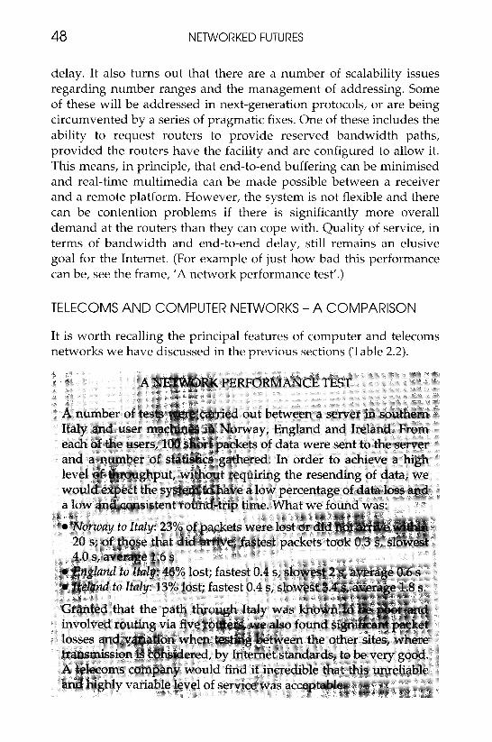
delay. It also turns out that there are a number of scalability issues regarding number ranges and the management of addressing. Some of these will be addressed in next-generation protocols, or are being circumvented by a series of pragmatic fixes. One of these includes the ability to request routers to provide reserved bandwidth paths, provided the routers have the facility and are configured to allow it. This means, in principle, that end-to-end buffering can be minimised and real-time multimedia can be made possible between a receiver and a remote platform. However, the system is not flexible and there can be contention problems if there is significantly more overall demand at the routers than they can cope with. Quality of service, in terms of bandwidth and end-to-end delay, still remains an elusive goal for the Internet. (For example of just how bad this performance can be, see the frame, 'A network performance test'.)
TELECOMS AND COMPUTER NETWORKS - A COMPARISON
It is worth recalling the principal features of computer and telecoms networks we have discussed in the previous sections (Table 2.2).
NEW NETWORK ARCHITECTURES 49
Table 2.2 Differences behveen telecom and computer networks
Feature Telecom network: Computer network
Bandwidth fixed, usually low bursty, with high capacity Multipoint capability poor good Remote access poor (but improving) good Location of intelligence in the centre in the terminal
Reliability very high poor Standardisation good poor
Bearing in mind that one of the major requirements for future networks will be to provide a fully satisfactory solution for multi- media communication, it turns out that neither of them is quite adequate. (But one possible early defector to 'computer networks' will be facsimile traffic: see the frame below, 'Facsimile, the forgotten service'.)
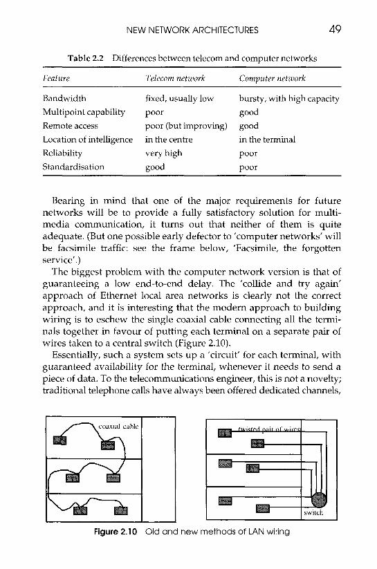
The biggest problem with the computer network version is that of guaranteeing a low end-to-end delay. The 'collide and try again' approach of Ethernet local area networks is clearly not the correct approach, and it is interesting that the modern approach to building wiring is to eschew the single coaxial cable connecting all the termi- nals together in favour of putting each terminal on a separate pair of wires taken to a central switch (Figure 2.10).
Essentially, such a system sets up a 'circuit' for each terminal, with guaranteed availability for the terminal, whenever it needs to send a piece of data. To the telecommunications engineer, this is not a novelty; traditional telephone calls have always been offered dedicated channels,
1 I I
Figure 2.10 Old and new methods of LAN wiring
50 NETWORKED FUTURES
of given bandwidth or bit-rate. In the early days each channel corres- ponded to a distinct pair of wires, although in more recent times the channels were combined onto the same physical medium by means of multiplexing techniques such as FDM, TDM and CDMA (see frames pages 100, 33 and 133, 'TDM, FDM,' CDMA). However, each of these channels had a specification which made them less than ideal for voice and almost unacceptable for today's data requirements. The problem with the specification was bandwidth, or, to be more accurate, the cost of it. The minimum acceptable bandwidth for speech is around 3 kHz, corresponding to a bit-rate of 10-60 Kbit/s (depending on how the speech is coded). It is reasonably accurate to say that this bandwidth is required most of the time the circuit is active.
Now, the market for voice telephony appears to be acceptable at the current costs of a few pence or cents for a minute or so of long- distance calling. However, a typical local area network operates at bursts of 10 Mbit/s or even more. This bandwidth is 1000 times greater than for telephony and it is unlikely that a market could be sustained for prices in this range, even allowing for bulk discounts! Remember, however, that we said that computer traffic was bursty and required this level of bandwidth only intermittently. If band-
NEW NETWORK ARCHITECTURES 51
width is going to remain relatively expensive (we shall look at the alternative scenario later), then the solution is obvious: we require to be able to create circuits whose bandwidth can change dynamically, in tune with the demands of the data.
CIRCUIT-SWITCHED AND PACKET-SWITCHED, CONNECTION- BASED AND CONNECTIONLESS
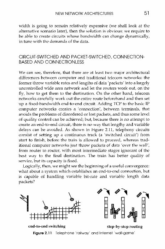
We can see, therefore, that there are at least two major architectural differences between computer and traditional telecom networks: the former throw variable rates and lengths of data ’packets’ into a largely uncontrolled wide area network and let the routers work out, on the fly, how to get them to the destination. On the other hand, telecom networks carefully work out the entire route beforehand and then set up a fixed-bandwidth end-to-end circuit. Adding TCP to the basic IP computer networks creates a ’connection’, between terminals, that avoids the problems of disordered or lost packets, and thus some level of quality control can be achieved; but, because there is no attempt to create an end-to-end circuit, there is no way that lengthy and variable delays can be avoided. As shown in Figure 2.11, telephony circuits consist of setting up a continuous track (a ‘switched circuit’) from start to finish, before the train is allowed to proceed, whereas trad- itional computer networks just throw packets of data ’over the wall’, from router to router, with most intermediate stages ignorant of the best way to the final destination. The train has better quality of service, but its capacity is fixed.
Logically, then, we might see the beginning of a useful convergence: what about a system which establishes an end-to-end connection, but is capable of handling variable bit-rate and variable length data packets?
end-to-end switching step-by-step routing
Figure 2.1 1 Telephone ‘railway’ and Internet ‘wall-game‘

52 NETWORKED FUTURES
ATM -TELECOMS’ ANSWER TO THE VARIABLE BANDWIDTH PROBLEM
The dominant architecture of telecommunications networks is, to this day, based on the concept of the fixed-bandwidth, semi-permanently switched circuit. The simplest example is the telephone call, where the local connection between the customer and the first switching point (e.g. a local exchange) has a fixed bandwidth (approximately 300-3000 Hz) for an analogue call, or 64 Kbit/s for a digital, ISDN call). Throughout the network path that continues on to the called party, the switching and the transmission equipment are all designed to pre- serve this constraint, which then impacts on the cost and price struc- ture to the operator and customer, respectively. Business customers may hire wider-band circuits, to connect their PABX’s or computers, but these two are constrained to a fixed bit-rate within well-defined digital hierarchies. Many of these circuits are permanently ’nailed up’ from origin to destination by infrequently changed data in exchange software, or even by real jumper-wires. The price is calculated as a fairly simple function of
0 fixed bit-rate 0 distance 0 duration of contract.
The true relationship between distance and cost to the network operator is becoming progressively much weaker and prices will eventually flatten accordingly, but costs for bit-rate and duration are much less flexible under the constraints of the current architectures. This is bad news for the bursty, intermittent signals from computer terminals. Network operators believe that the medium term (which could take us as far as 2020, in their planning terms) lies with Asynchronous Transfer Mode (ATM), which provides a way to set up and take down, very rapidly, circuits with variable bandwidth but also possessing low end-to-end delay.
ATM works on the principle of statistical multiplexing: the fact that combining a number of individually fluctuating channels results in the creation of a larger channel with lower percentage fluctuation which can thus be more heavily loaded without overloading (see frame). Suppose we have a number of individual channels, A, b, . . ., z , which will not, in general, contain data at a steady rate. We combine them through a ’multiplexor’ onto one transmission circuit, on the basis of allocating each channel a fixed-length chunk of data (called a

NEW NETWORK ARCHITECTURES 53
A
Figure 2.12 ATM multiplexing at one instant
A
Figure 2.13 ATM multiplexing at another instant
‘cell’), depending on need. So, if we monitored the output of the multiplexor, we might see at one instant (Figure 2.12) that source A is relatively busy. At a different time, which could be milliseconds or hours away, we might see the picture shown in Figure 2.13. This time, A has required only one-fifth of the previous data rate (and might expect to pay accordingly).
54 N E T W O R K E D FUTURES
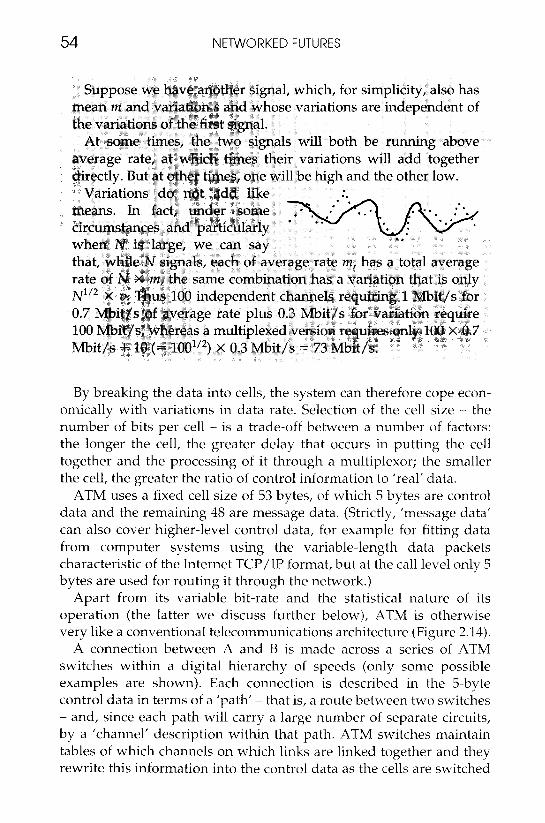
By breaking the data into cells, the system can therefore cope econ- omically with variations in data rate. Selection of the cell size - the number of bits per cell - is a trade-off between a number of factors: the longer the cell, the greater delay that occurs in putting the cell together and the processing of it through a multiplexor; the smaller the cell, the greater the ratio of control information to ’real’ data.
ATM uses a fixed cell size of 53 bytes, of which S bytes are control data and the remaining 48 are message data. (Strictly, ’message data’ can also cover higher-level control data, for example for fitting data from computer systems using the variable-length data packets characteristic of the Internet TCP/IP format, but a t the call level only 5 bytes are used for routing it through the network.)
Apart from its variable bit-rate and the statistical nature of its operation (the latter we discuss further below), ATM is otherwise very like a conventional telecommunications architecture (Figure 2.14).
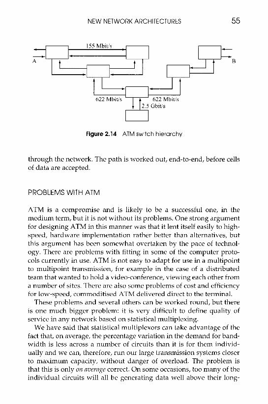
A connection between A and B is made across a series of ATM switches within a digital hierarchy of speeds (only some possible examples are shown). Each connection is described in the S-byte control data in terms of a ’path’ - that is, a route between two switches - and, since each path will carry a large number of separate circuits, by a ‘channel’ description within that path. ATM switches maintain tables of which channels on which links are linked together and they rewrite this information into the control data as the cells are switched
NEW NETWORK ARCHITECTURES 55
2.5 Gbit/s
Figure 2.14 ATM switch hierarchy
through the network. The path is worked out, end-to-end, before cells of data are accepted.
PROBLEMS WITH ATM
ATM is a compromise and is likely to be a successful one, in the medium term, but it is not without its problems. One strong argument for designing ATM in this manner was that it lent itself easily to high- speed, hardware implementation rather better than alternatives, but this argument has been somewhat overtaken by the pace of technol- ogy. There are problems with fitting in some of the computer proto- cols currently in use. ATM is not easy to adapt for use in a multipoint to multipoint transmission, for example in the case of a distributed team that wanted to hold a video-conference, viewing each other from a number of sites. There are also some problems of cost and efficiency for low-speed, commoditised ATM delivered direct to the terminal.
These problems and several others can be worked round, but there is one much bigger problem: it is very difficult to define quality of service in any network based on statistical multiplexing.
We have said that statistical multiplexors can take advantage of the fact that, on average, the percentage variation in the demand for band- width is less across a number of circuits than it is for them individ- ually and we can, therefore, run our large transmission systems closer to maximum capacity, without danger of overload. The problem is that this is only on average correct. On some occasions, too many of the individual circuits will all be generating data well above their long-
56 NETWORKED FUTURES
term average, and things are going to overflow. The statistics of the traffic cause enormous problems directly to the network provider, in terms of getting the transmission quality to an acceptable standard at an economic cost, and indirectly to the customers, who need know nothing about the solutions adopted but are critically interested in the price. Consider, for example, the ’simple’ case of customers who agree that they will never send data at rates higher than 100 Mbit/s. But do they mean one single 100 Mbit packet every second, or 1 Kbit every 10 microseconds? Clearly, the effects on the network will be different.
ATM FLOW CONTROL AND SERVICE POLICIES
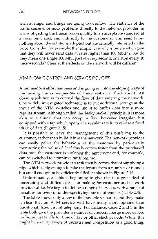
A tremendous effort has been and is going on into developing ways of minimising the consequences of these statistical fluctuations. An obvious solution is to control the flow of data entering the network. One widely investigated technique is to put additional storage at the input of the ATM switches and use it to buffer data into a more regular stream. Although called the ’leaky bucket’ principle, it is more akin to a funnel that can accept a flow however irregular, but equipped with a tap which opens at a regular rate R, to release a fixed ’drip’ of data (Figure 2.15).
It is possible to leave the management of this buffering to the customer, rather than build it into the network. The network provider can easily police the behaviour of the customer by periodically monitoring the value of R: if this becomes faster than the purchased data-rate, the customer is violating the agreement and, for example, can be switched to a punitive tariff regime.
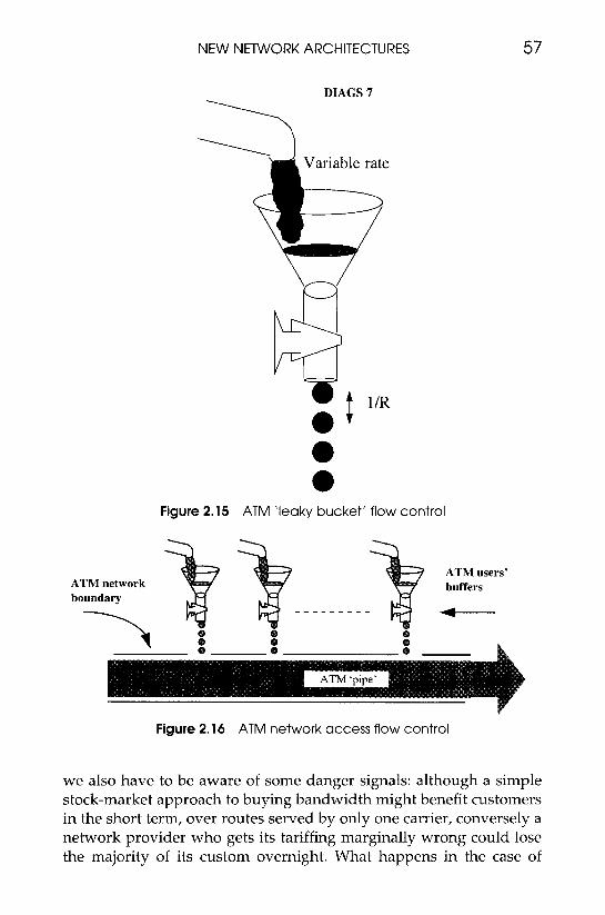
The ATM network provider’s task then becomes that of supplying a pipe which is big enough to take the inputs from a number of funnels but small enough to be efficiently filled, as shown in Figure 2.16.
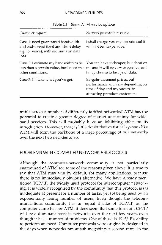
Unfortunately, all this is beginning to give rise to a great deal of uncertainty and difficult decision-making for customer and network provider alike. We begin to define a range of services, with a range of penalties for over- or under-specifying our requirements (Table 2.3).
The table shows only a few of the possible scenarios, but they make it clear that an ATM service will have many more options than traditional, fixed circuit telephony. For instance, cases 2 and 3 in the table both give the provider a number of choices: charge more or lose traffic, adjust tariffs for time of day or other slack periods. Whilst this might be seen by lovers of unrestrained competition as a good thing,
NEW NETWORK ARCHITECTURES 57
Figure 2.15 ATM ’leaky bucket’ flow control
Figure 2.16 ATM network access flow control
we also have to be aware of some danger signals: although a simple stock-market approach to buying bandwidth might benefit customers in the short term, over routes served by only one carrier, conversely a network provider who gets its tariffing marginally wrong could lose the majority of its custom overnight. What happens in the case of
58 NETWORKED FUTURES
Table 2.3 Some ATM service options
Customer require Netzuork provider’s response
Case 1: need guaranteed bandwidth and end-to-end fixed and short delay e.g. for voice), with set limits on data loss.
Case 2: I estimate my bandwidth to be less than a certain value, but I need the other conditions.
Case 3: 1/11 take what you‘ve got.
I shall charge you my top rate and it will not be inexpensive.
You can have it cheaper, but cheat on me and it will be very expensive, or I I may choose to lose your data.
Bargain-basement prices, but performance will vary depending on time of day and my success in attracting premium customers.
traffic across a number of differently tariffed networks? ATM has the potential to create a greater degree of market uncertainty for wide- band services. This will probably have an inhibiting effect on its introduction. However, there is little doubt that statistical systems like ATM will form the backbone of a large percentage of our networks over the next two decades or so.
PROBLEMS WITH COMPUTER NETWORK PROTOCOLS
Although the computer-network community is not particularly enamoured of ATM, for some of the reasons given above, it is true to say that ATM may win by default, for many applications, because there is no immediately obvious alternative. We have already men- tioned TCP/IP, the widely used protocol for intercomputer network- ing. It is widely recognised by the community that this protocol is (a) inadequate at present for a number of tasks, yet (b) being used by an exponentially rising number of users. Even though the telecom- munications community has an equal dislike of TCP/IP as the computer camp has for ATM, it does seem that some form of TCP/IP will be a dominant force in networks over the next few years, even though it has a number of problems. One of those is TCP/IP’s ability to perform at speed. Computer protocols were originally designed in the days when networks ran at sub-megabit per second rates. In the
NEW NETWORK ARCHITECTURES 59
chapter which follows, we are going to discuss the possibility of wide area transmission at gigabits per second. Not unnaturally, this is going to pose a problem for existing practices. A few pages back, we described how data packages were acknowledged by the receiving computer and, provided this acknowledgement got back to the sender within a certain time, then it did not need to resend data. In fact, this time limit was determined by the size of the sending computer’s output buffer. If the buffer emptied before the acknowledgement was returned, then the sender had to take appropriate action. Suppose the buffer is N bits long and the transmission rate is R. The buffer will empty in time N / R . This time must be at least as long as the time taken for the first bit of data to go from sender to receiver and for the receiver to acknowledge it. Suppose we have a 500 km line. Even if this is a single optical fibre, with no intervening switches or routers, the round-trip time will be of the order of 1/200 S. So:
N / R must be greater than 1/200
that is, N must be greater than R/200. This is no problem if the data- rate is, say, 2 Mbit/s. We can easily have a buffer of 10 kilobits. If the data-rate goes up to gigabit per second rates, then we begin to talk about quite large buffer sizes. There is another problem. Suppose we have an error in the data. This will not be relayed back to the sender until an enormous amount of data has been received. Currently, pro- tocols tend to retransmit multiple packets after an error is detected. This seriously limits transmission speeds, when we are delay-limited, rather than bit-rate-limited, by the transmission system.
There are other protocol issues that require changing, if computer systems are to make full use of ultra-hgh-speed networks. For instance, many of the current methods are heavily biased towards recovery after relatively frequent transmission errors. New transmission sys- tems based on fibre will greatly reduce the error rates encountered and this should be capitalised on. In general, computer protocol engineering needs to look beyond the relatively short-term gains to be achieved by modifications to TCP/IP and so on.
PROTOCOL CONVERGENCE?
Where therefore do we go from here in trying to reconcile the pro- tocols that were originally designed to meet different requirements at the time when bit rates were more modest and the requirement for

60 NETWORKED FUTURES
real-time multimedia was not considered significant? One possibility is out-and-out war between the end-to-end switchers and the hop-by- hop routers. This is a real possibility, albeit a rather frightening one, but it is perhaps better to concentrate on more hopeful outcomes. It is possible that some accommodation can be achieved.
In particular, we should remember that protocols achieve their greatest elaboration and least flexibility when they are trying to squeeze a quart into a pint pot. IP, the very simple datagram service, had to be enhanced by TCP, in order to achieve some level of quality of service, in the hostile, error-prone, bit-rate-limited, unregulated Internet. ATM, on the other hand, has a rather rigid structure, partly at least because of speed restrictions on the switching fabric. Optical fibre transmission, with its enormous bandwidth and very low error rates, may allow us to relax the strait-jacketed protocols. One possi- bility that is emerging is for IP packets to be run on top of an ATM- based network, with the routing being done using IP methods but ATM principles being used to control the flow of data into the network, using the leaky bucket principle. This is a bit of a 'bodge', but is, at least, a sensible compromise for some types of traffic, and could be the seeds of a new set of protocols. Some research teams have suggested that it is possible and desirable to integrate the data routing of IP and ATM into one scheme. They also suggest that this combined scheme should, however, offer two classes of service: one which does a best-efforts delivery and the other which promises to meet specified quality of service.
THE SPECIAL CASE OF THE LOCAL LOOP
The majority of the transmission cost in a telecommunications net- work is not in the long-haul routes, but in the cables to our homes and offices. Despite the radical changes in the long-haul - coaxial cable replacing pairs of wires and, more recently, the introduction of fibre optics and satellite - the vast majority of telephone connections are carried 'the last mile' in the local loop over copper pairs of wires. This is even true in the case of telephony delivered by CATV companies, who use coaxial cable for delivery of TV into the home, but run the telephony connection separately, on copper pairs. Only in the case of multiline business premises are optical fibre or radio links becoming the predominant technology. It is currently considered too expensive to rip out existing domestic cable and replace it with fibre, and the
NEW NETWORK ARCHITECTURES 61
optical transmitters and receivers are still too expensive on a single- line basis, if one is providing only telephony.
Coaxial Cable Solutions
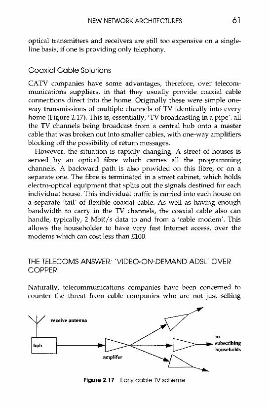
CATV companies have some advantages, therefore, over telecom- munications suppliers, in that they usually provide coaxial cable connections direct into the home. Originally these were simple one- way transmissions of multiple channels of TV identically into every home (Figure 2.17). This is, essentially, ’TV broadcasting in a pipe’, all the TV channels being broadcast from a central hub onto a master cable that was broken out into smaller cables, with one-way amplifiers blocking off the possibility of return messages.
However, the situation is rapidly changing. A street of houses is served by an optical fibre which carries all the programming channels. A backward path is also provided on this fibre, or on a separate one. The fibre is terminated in a street cabinet, which holds electro-optical equipment that splits out the signals destined for each individual house. This individual traffic is carried into each house on a separate ’tail’ of flexible coaxial cable. As well as having enough bandwidth to carry in the TV channels, the coaxial cable also can handle, typically, 2 Mbit/s data to and from a ’cable modem’. This allows the householder to have very fast Internet access, over the modems which can cost less than €100.
THE TELECOMS ANSWER: ‘VIDEO-ON-DEMAND ADSL’ OVER COPPER
Naturally, telecommunications companies have been concerned to counter the threat from cable companies who are not just selling
Y receive antenna
I to
hub subscribing households -
Figure 2.17 Early cable TV scheme
62 NETWORKED FUTURES
access to CATV, but also frequently packaging it with telephony. One solution, ’video-on-demand using asymmetric digital subscriber loop (ADSL)’ is a system for sending TV-quality images over the existing copper pairs of wires that carry domestic telephony.
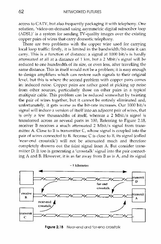
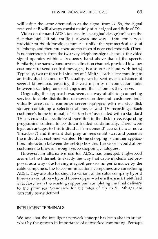
There are two problems with the copper wire used for carrying local loop traffic: firstly, it is limited in the bandwidth/bit-rate it can carry. This is a function of distance: a signal at 1000 bit/s is hardly attenuated at all at a distance of 1 km, but a 2 Mbit/s signal will be reduced to one hundredth of its size, or even less, after travelling the same distance. This in itself would not be a problem; it is easy enough to design amplifiers which can restore such signals to their original level, but this is where the second problem with copper pairs comes in: induced noise. Copper pairs are rather good at picking up noise from other sources, particularly those on other pairs in a typical multipair cable. This problem can be reduced somewhat by twisting the pair of wires together, but it cannot be entirely eliminated and, unfortunately, it gets worse as the bit-rate increases. Our 1000 bit/s signal will induce a version of itself into an adjacent pair of wires, that is only a few thousandths of itself, whereas a 2 Mbit/s signal is transferred across as several parts in 100, Referring to Figure 2.18, receiver B receives a much attenuated 2 Mbit/s signal from trans- mitter A. Close to B is transmitter C, whose signal is coupled into the pair of wires connected to B. Because C is close to B, its signal (called ’near-end crosstalk’) will not be attenuated much and therefore completely drowns out the faint signal from A. But consider trans- mitter D. It too is generating a ’crosstalk’ signal into the pair connect- ing A and B. However, it is as far away from B as is A, and its signal
- 1 kilometre
4 b
XY xx M XY m xx =- transmit
far-end crosstalk
D
receive . ransmit B
near-end crnsstalk
.ransmit c 7x XY
Figure 2.18 Near-end and far-end crosstalk
NEW NETWORK ARCHITECTURES 63
will suffer the same attenuation as the signal from A. So, the signal received at B will always consist mainly of A's signal and little of D's.
Video-on-demand ADSL (at least in its original design) relies on the fact that high bit-rate traffic is always one-way - from the service provider to the domestic customer - unlike the symmetrical case of telephony, and therefore there are no cases of near-end crosstalk. (There is no interference from the two-way telephony signal, because the video signal operates within a frequency band above that of the speech. Similarly, the narrowband reverse direction channel, provided to allow customers to send control messages, is also out of band with both.) Typically, two or three bit streams of 2 Mbit/s, each corresponding to an individual channel of TV quality, can be sent over a distance of several kilometres, covering the vast majority of connection links between local telephone exchanges and the customers they serve.
Originally, this approach was seen as a way of offering competing services to cable distribution of movies on demand: customers indi- vidually accessed a computer server equipped with massive disk storage containing a selection of movies and TV recordings. Each customer's home terminal, a "set-top box' associated with a standard TV set, created a specific read operation to the disk drive, requesting programme content to be down loaded continuously. There were legal advantages to this individual 'on-demand' access (it was not a 'broadcast') and it meant that programmes could start and pause as the individual customer wanted. Home shopping is another applica- tion: interaction between the set-top box and the server would allow customers to browse through video shopping catalogues.
However, an alternative use for ADSL has emerged: high-speed access to the Internet. In exactly the way that cable modems are pro- posed as a way of achieving megabit per second performance by the cable companies, the telecommunications companies are considering ADSL. They are also looking at a variant of the cable company hybrid fibre-coax solution - hybrid fibre-copper - where there is a street feed over fibre, with the existing copper pair completing the final delivery to the premises. Standards for bit rates of up to 51 Mbit/s are currently being defined.
INTELLIGENT TERMINALS
We said that the intelligent network concept has been shaken swne- what by the growth in importance of networked computing. Perhaps
64 NETWORKED FUTURES
the major impact will be from the existence of intelligence in the terminal. Even in the intelligent network, telephones are expected to be relatively ‘dumb’. It will be necessary for the telephone to interact with the service switching point, for example, to retrieve messages from an intelligent peripheral acting as a networked answering machine, but these interactions are assumed to be relatively un- complicated and could be evoked by using standard multi-frequency tones generated from a simple telephone’s keypad.
The tones are interpreted at the service switching point and con- verted into messages carried over the signalling channel, to the service control point. The telephone interacts with only one network; its signalling (tones) and traffic (speech) are, for at least part of the route, carried over the same path, and the intelligent processing is done by the central intelligence of the network.
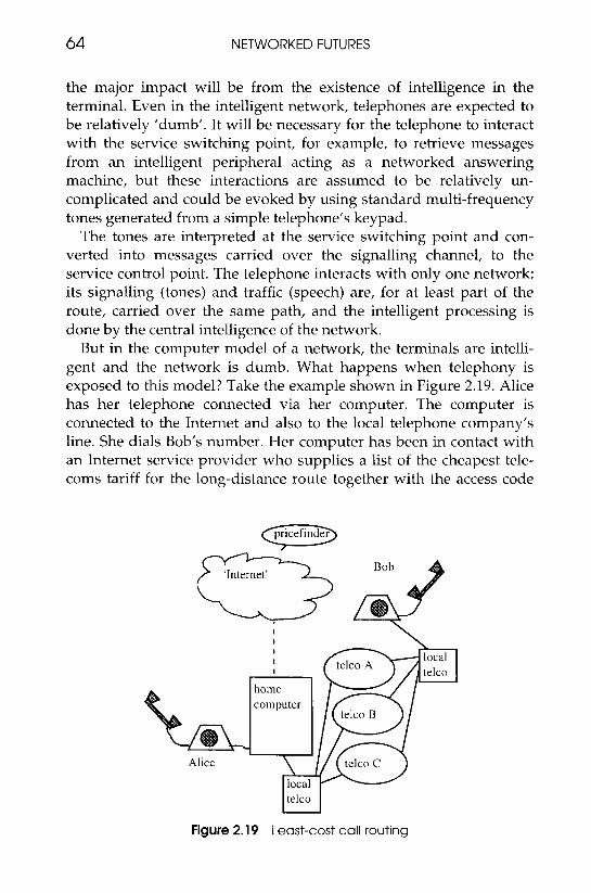
But in the computer model of a network, the terminals are intelli- gent and the network is dumb. What happens when telephony is exposed to this model? Take the example shown in Figure 2.19. Alice has her telephone connected via her computer. The computer is connected to the Internet and also to the local telephone company’s line. She dials Bob’s number. Her computer has been in contact with an Internet service provider who supplies a list of the cheapest tele- coms tariff for the long-distance route together with the access code
a pricefinder
l
Alice
. l I local I telco
home computer
I local lteico I
Figure 2.19 Least-cost call routing
NEW NETWORK ARCHITECTURES 65
that has to be dialled. Alice’s computer does a number translation from the number she dialled to that of the cheapest route and then dials that number. What Alice has done is to bypass the central control of the service creation environment, the service control point and, in fact, the entire architecture of the telecoms company’s intelli- gent network. (At the time this was first written, this scenario was considered to be only a theoretical possibility and rather discounted by traditionalists. It is now a reality.)
In the ultimate, the terminal could post a request for tender each time it wanted to make a call and could then sit back waiting for the best offer.
LOW-COST VIRTUAL PRIVATE NETWORKS
There are other services that can bypass some of the functions once expected to be the preserve of a centralised intelligent network. One further example is as follows. Imagine setting up a virtual private network, consisting of a telephone and data network, where people’s addresses and telephone numbers are logically assigned for the dura- tion of a project. With simple telephones as the only voice terminals this would require configuration of a network switch, the value- added contribution of the network provider, but if telephony is mediated by the workstation, then it can perform number translation and even hold call records for interdivisional charging. In the next few years the power of personal computers will be sufficiently great to allow them to carry out much of the control of the call, if a mechanism exists for mapping this intelligence onto the switching. If this is the case, ownership of the routing largely passes from the carrier to the customer.
How this will happen in detail is up for debate. In the examples given, the computer has carried out intelligent control independently of the telecoms network, in some cases making use of a parallel data network (the Internet). This is an extreme reaction to the earlier centralised model of control. An alternative might be a more co- operative regime where the local intelligence of the terminal interacted with the service control point of the intelligent network. A logical option might be to ask the user’s terminal to configure the features and requirements to meet individual needs at individual instances, for instance, to find the cheapest available provider of a video-conference, and use the central intelligence of the network for issues of scale, such
66 N E T W O R K E D FUTURES
as configuration of global number plans for a virtual private network, the centralised distribution of voice announcements, universal access between fixed and mobile services, and so on.
INFORMATION NETWORKS
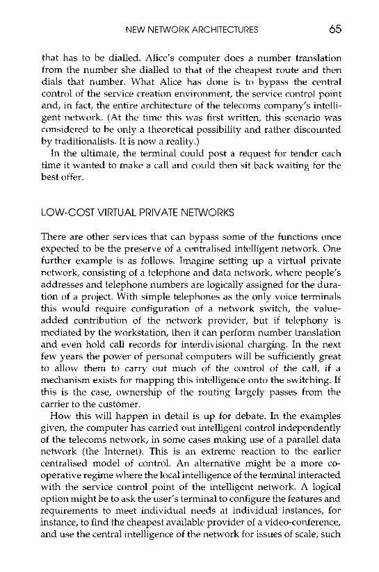
A further conceptual change required from telecommunications com- panies is in coming to terms with the fact that communications is not necessarily about people talking to each other or even for computers doing the same. In particular, it is not necessarily about a simple setting up and closing down of a connection, with symmetrical flows of data between the two parties. In many cases, the interaction will be highly unequal, between ’consumers’ of information and its ’suppliers’ (Figure 2.20).
There will be a large number of consumers, equipped with rel- atively cheap terminals - home computers, personal (mobile) organ- isers, multimedia telephones, digital TV sets - who will access a relatively small number of suppliers, typically larger computers that contain multimedia information or entertainment, that can be supplied to individual consumers, ‘on demand’. Data flows in such applica- tions are largely one-way: the consumer gives relatively simple, short, slow commands (by mouse or keyboard now, perhaps by voice in the future) to the supplier, who returns vast volumes of data at a very high rate - typically, perhaps 32 Kbit/s of requests (i.e. the capacity of one voice-grade telephone line) against at least 2 Mbit/s from the supplier (for TV-quality video and sound).
A number of changes to the way telecommunications companies
‘The network’
Figure 2.20 Information network

NEW NETWORK ARCHITECTURES 67
need look at standards arise from this movement away from real-time voice: the needs of entertainment and information services are very different from that of interactive voice and videophone. Consider the last: the video image has to be captured, coded and decoded equally at both ends of the call, and with as little delay as possible. This is not true in entertainment services; because there are fewer suppliers (who encode the material) than receivers (who decode it), it is advan- tageous to use expensive coding equipment for the former, and inexpensive decoders. Also, there is no pressing need to encode without delay; the exchange is not real-time interactive.
’Information services’, by which we mean extensions to the content and services currently available on the Internet, raise another com- plication: what protocols will we use for delivering the signals to our home computers and set-top boxes? The current favourite is to use Internet protocols. These, as we have seen, however, are still some- what deficient in terms of quality of service. There are likely to be significant developments in this area over the next decade, before the issue is finally resolved.
MOBILE CODE AND NETWORK ‘AGENTS’
Despite the significant difference between current computer and tele- communications architectures, they both tend to localise their methods of control. Telecommunications networks, as we have seen, have guarded very jealously the authority of the centre to possess the intelligence and the power to control things. Computer networks allow more autonomy to the ’peripherals’ (the computers at the ends of the network) but the control possessed by the terminals is strictly over their own domains. When computers cooperate on a task, they tend to do so by passing each other data, i.e. ‘data’ in the sense that it is used as such by the remote processor, not as ’code’. The machine receiving the data is still completely in control of its local processes.
Recently there have been interesting developments in approaches to communication across networks, and also in network management, that have employed a rather different approach to communication and control architectures, one that employs mobile software agents - pieces of executable code -that traverse the network and execute their instructions on its control elements and the computers and other terminals at the ends.
At this point, a warning: there is considerable discussion about
68 NETWORKED FUTURES
precisely what is meant by an ’intelligent agent’ - the term is used in many ways and in order to follow fashion, overuse has tended to devalue its meaning. ‘Agent’ is more of a phenomenalistic and anthropomorphic term than a description of the interior workings; ’agents’ are thought of in terms of artificial intelligence entities that in some way behave like human ’agents’ - as autonomous individuals that negotiate and communicate and move about. The metaphor is striking and useful, but must not be overdone. Instead, we shall look at some applications.
The ‘Singing Telegram’
This very simple example is possible today, using programming languages such as Java (see the frame on ’Portable code’): Alice wants to send a birthday message to Bob, to appear on Bob’s computer terminal. She connects to a World Wide Web site on the Internet that specialises in greeting cards. She chooses one that she likes and fills in an online form that will personalise the greeting. When Bob next accesses his terminal, the greeting card will have been sent in the form of a small portion of code and data. When Bob activates the greeting, probably within a Net Browser, the code will be automatically trans- lated on his machine and will be executed: perhaps a dancing bottle will move across the screen, singing.
’To the birthday boy within his palace, Let me take you for a chalice, Of wine at Rizi’s, Love from Alice’.
(Unfortunately technology does not automatically guarantee taste or talent.) Bob can then click on the ‘yes, let’s!’ button that goes with the greeting, to automatically return an acknowledgement.
Agents for Mobile Users
The above example demonstrated that terminals could operate as pairs of distributed computing engines, with one terminal running code supplied by another. In that example, the network was involved only for transporting the code. Now consider the case of a business executive on the move: she wants to arrange a new venue for a meeting with a client and also plan travel and accommodation to coincide with the meeting. The problem is, she is shortly going to

NEW NETWORK ARCHITECTURES 69
board an aeroplane inside which communication will not be possible. There is enough time to use a personal communicator to fire off an agent into the network, bearing a set of instructions: the agent has to communicate with the client’s electronic diary to find a meeting date, then contact a travel office to book flights, hotels, etc., and possibly transfer securely payment from the executive’s bank. Once this is done (or, alternatively, when it is discovered that alternative arrange- ments are required), the executive must be contacted to give confirmation. Much of the processing will again have been carried out at the periphery, but there will be a need to locate the various services (bank, travel agent, etc.) using ‘Yellow Pages’ directory services and there will need to be quite a complex call redirection service. There is considerable potential for the ’intelligent network’ concept to find an application here.
70 NETWORKED FUTURES
Agents Within the Network
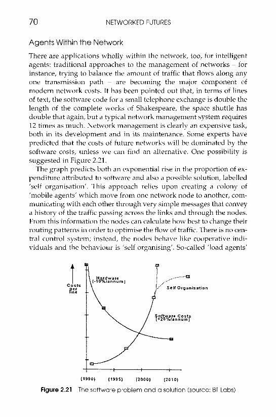
There are applications wholly within the network, too, for intelligent agents: traditional approaches to the management of networks - for instance, trying to balance the amount of traffic that flows along any one transmission path - are becoming the major component of modern network costs. It has been pointed out that, in terms of lines of text, the software code for a small telephone exchange is double the length of the complete works of Shakespeare, the space shuttle has double that again, but a typical network management system requires 12 times as much. Network management is clearly an expensive task, both in its development and in its maintenance. Some experts have predicted that the costs of future networks will be dominated by the software costs, unless we can find an alternative. One possibility is suggested in Figure 2.21.
The graph predicts both an exponential rise in the proportion of ex- penditure attributed to software and also a possible solution, labelled ’self organisation’. This approach relies upon creating a colony of ’mobile agents’ which move from one network node to another, com- municating with each other through very simple messages that convey a history of the traffic passing across the links and through the nodes. From this information the nodes can calculate how best to change their routing patterns in order to optimise the flow of traffic. There is no cen- tral control system; instead, the nodes behave like cooperative indi- viduals and the behaviour is ’self organising’. So-called ’load agents’
(1990) ( 1 9 9 5 ) ( Z O O O l ( 2 0 1 0 )
Figure 2.21 The software problem and a solution (source: BT Labs)
NEW NETWORK ARCHITECTURES 71
are sent to each of these nodes, by ’parent agents’ who have been wandering at random around the network, collecting information on how much traffic is arriving at the nodes and the node capacity. When a load agent arrives on a node, it updates the route from that node to all the other nodes by modifying appropriate routing tables through- out the network. Once it has visited a node and made the appropriate modifications, then it moves to another node and repeats the calcula- tion. The agent has acted ’autonomously’ and has communicated with other agents only via the changes it has made to the routing table.
On its travels, the parent agent may find ’crashed agents’ - agents whose time-stamp to complete the task has exceeded a threshold. It will remove these agents, reset the records and launch another agent. Thus nodes may have several agents working on their routing tables at once. Parents also require to be managed. On some nodes reside static processes which hold a preset figure for the number of parents they will try to maintain in the network. Whenever a parent visits a node, the process reads its name and when it started. If there are many parents on the network, some measure of culling is required. Usually it will be the youngest agents that are removed, since their historical records are least valuable. Sometimes, however, analysis of the visiting patterns of agents revealed that they are ‘crashed’. In this case, irrespective of age, they will be removed.
This design is very robust and can handle many process errors, link and node failures and need not be equipped with accurate network statistics at initiation time. The code required to implement it is rel- atively compact and highly scaleable - all that is required is to replicate more agents.
POSITIVE ASPECTS OF DISTRIBUTED AGENTS
We can see from the examples above that there are a number of very positive reasons for the introduction of agents into distributed networks:
e They are relatively small units of code that communicate with other agents and processes through simple, well-defined messages - thus their operations are individually easier to verify than those of monolithic programs.
e This also makes them suitable for designing applications that run across a variety of platforms from a plurality of service providers.

72 NETWORKED FUTURES
0 Mobile agents can be injected into a network from terminals that are not continuously in reliable contact with the network (e.g. from mobile units).
0 The agents are distributed across the network and its terminals; thus, inherently they mimic the network’s resilience and redundancy.
MOBILE AGENTS - UNRESOLVED ISSUES
There are, however, a number of question marks still hanging over the wholesale use of mobile agents. Firstly, there is the question of security: a piece of mobile code sent to you by someone else, that runs on your computer, is perilously close to being a computer virus. How do you know that what you have permitted to run on your machine is what you think it is? How do you protect yourself from it doing damage to your files or, perhaps more serious because it is not so obvious, how do you stop it sending details from them, back over the network to the sender?
It is the flexibility of computer designs that allow them to take advantage of the potential for the running of remote code, but this flexibility is also a security weakness. As it stands today, there are risks created by mobile code running on today’s machines. Some of these will be removed in time, but mobile code will always provide a relatively equal battleground for the hacker and the security guard.
Secondly, there is the issue of guaranteeing performance: in many cases it is possible to give examples of agent-based design producing solutions that are more cost-effective than traditional methods. But these are on a case-by-case basis. It is extremely difficult to give a reasonably rigorous proof that the agent solution will be ’generally’ better, or indeed reliable. The problem is that the more intelligent, cooperative agents that are required for realistically sized problems possess adaptive structures and exhibit ’emergent behaviour’ - that is, behaviour whose properties are not easily deducible before they are set loose and self-trained on the real data. There will have to be some very impressive demonstrations of cost-saving and performance before the relatively conservative network operators will carry out sizeable, live trials of agent-based software, on critical tasks in the network management domain.

NEW NETWORK AFCHITECTURES 73
DISTRIBUTED COMPUTING ARCHITECTURES
The creation of 'virtual organisations' - business enterprises where different trading partners, perhaps on other continents, combine together to create the end-to-end val.ue chains necessary to market a new product or service - will demand a concerted approach to the creation of distributed computing environments to support the enter- prise. There must be a degree of cooperation between the applications that run on computers on the different sites (some of which may belong to other companies and employ equipment from different manufacturers), there will be 'resource sharing' of powerful com- puters, storage or peripherals, and all of this must be as transparent as possible to the user and be capable of fail-safe operation in the event of a link or machine fault.
Quite a large amount of distributed computing goes on at present, of course: computers in different companies communicate automatic- ally with each other in the form of e-mails or electronic data inter- change (EDI) transactions (see frame). The interfaces between the
74 NETWORKED FUTURES
computers are, however, restricted to the passing of messages, that is, ’data’, without the power to control processes, i.e. ’programs’, running on the other machine.
There are also large networks of computers that operate between widely separated sites of individual companies, and these can initiate processes on remote machines, but under highly controlled circum- stances and only on machines of compatible design.
Some degree of cooperative computing occurs over the Internet; at least two examples are worth noting in this context. Users who access remote ’Web servers’ by typing in a URL can, provided the server permits them to do so, send parameters to the server that will start processes running on the server, using a message described in a standard format, the ’Common Gateway Interface’ (CGI) protocol. The second example is in the translation of the URLs themselves; URLs are names, not addresses. To be of use in connecting between a client computer requesting the service and a server offering it, the server’s URL must be converted to an address (which is then used by the network routers in order to work out the correct network paths to follow). Domain Name Servers are provided in a number of the subnetworks that comprise the Internet to perform this function. Software in the individual client terminals can store some name to address information, but, when a new URL is used, the client contacts the Domain Name Server for the translation. We shall see later how the principles of translation services such as this play an important part in distributed computing design.
ADVANCED DESIGNS FOR DISTRIBUTED COMPUTING
Within the last decade, a considerable amount of research has gone on into the best way to represent the architectural issues of distributed computing and also into the implementation of purist and pragmatic solutions. It is true to say that the final, definitive play-off between these solutions has not been resolved (and will probably be as much a marketing as a technical superiority result). However, it is also true to say that the different solutions appear to be migrating towards a high degree of consensus, or at least interoperability. Bearing these points in mind, we shall look briefly at one of the leading contenders, which embodies well the current thinking.
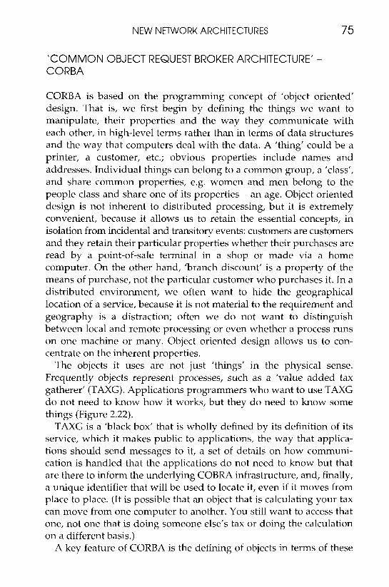
NEW NETWORK ARCHITECTURES 75
‘COMMON OBJECT REQUEST BROKER ARCHITECTURE‘ - CORBA
CORBA is based on the programming concept of ’object oriented’ design. That is, we first begin by defining the things we want to manipulate, their properties and the way they communicate with each other, in high-level terms rather than in terms of data structures and the way that computers deal with the data. A ’thing’ could be a printer, a customer, etc.; obvious properties include names and addresses. Individual things can belong to a common group, a ’class’, and share common properties, e.g. women and men belong to the people class and share one of its properties - an age. Object oriented design is not inherent to distributed processing, but it is extremely convenient, because it allows us to retain the essential concepts, in isolation from incidental and transitory events: customers are customers and they retain their particular properties whether their purchases are read by a point-of-sale terminal in a shop or made via a home computer. On the other hand, ’branch discount’ is a property of the means of purchase, not the particular customer who purchases it. In a distributed environment, we often want to hide the geographical location of a service, because it is not material to the requirement and geography is a distraction; often we do not want to distinguish between local and remote processing or even whether a process runs on one machine or many. Object oriented design allows us to con- centrate on the inherent properties.
The objects it uses are not just ’things’ in the physical sense. Frequently objects represent processes, such as a ’value added tax gatherer’ (TAXG). Applications programmers who want to use TAXG do not need to know how it works, but they do need to know some things (Figure 2.22).
TAXG is a ’black box’ that is wholly defined by its definition of its service, which it makes public to applications, the way that applica- tions should send messages to it, a set of details on how communi- cation is handled that the applications do not need to know but that are there to inform the underlying COBRA infrastructure, and, finally, a unique identifier that will be used to locate it, even if it moves from place to place. (It is possible that an object that is calculating your tax can move from one computer to another. You still want to access that one, not one that is doing someone else’s tax or doing the calculation on a different basis.)
A key feature of CORBA is the defining of objects in terms of these
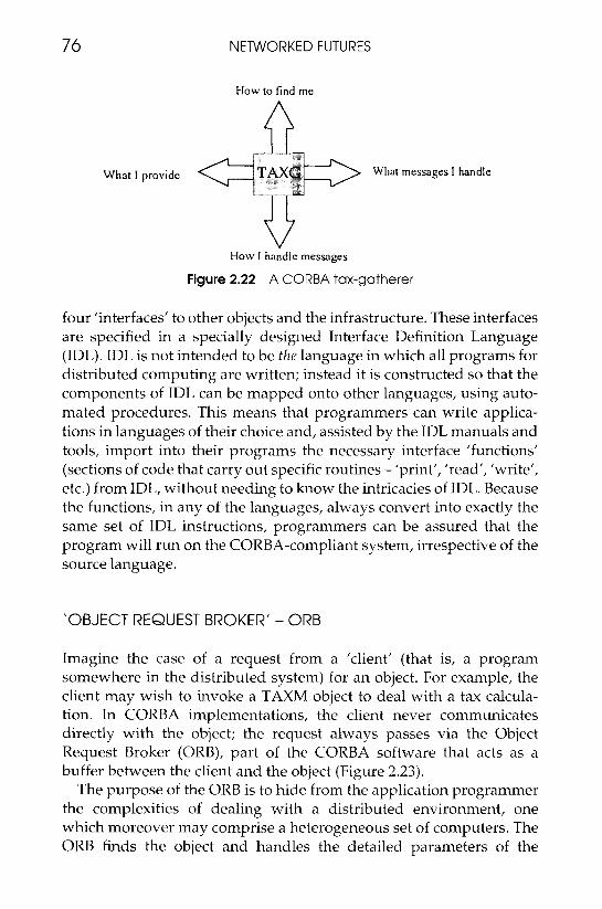
76 N E T W O R K E D FUTURES
How to find me
V How I handle messages
Figure 2.22 A CORBA tax-gatherer
four ’interfaces’ to other objects and the infrastructure. These interfaces are specified in a specially designed Interface Definition Language (IDL). IDL is not intended to be the language in which all programs for distributed computing are written; instead it is constructed so that the components of IDL can be mapped onto other languages, using auto- mated procedures. This means that programmers can write applica- tions in languages of their choice and, assisted by the IDL manuals and tools, import into their programs the necessary interface ’functions’ (sections of code that carry out specific routines - ’print’, ’read’, ’write’, etc.) from IDL, without needing to know the intricacies of IDL. Because the functions, in any of the languages, always convert into exactly the same set of IDL instructions, programmers can be assured that the program will run on the CORBA-compliant system, irrespective of the source language.
‘OBJECT REQUEST BROKER’ - O R B
Imagine the case of a request from a ’client’ (that is, a program somewhere in the distributed system) for an object. For example, the client may wish to invoke a TAXM object to deal with a tax calcula- tion. In CORBA implementations, the client never communicates directly with the object; the request always passes via the Object Request Broker (ORB), part of the CORBA software that acts as a buffer between the client and the object (Figure 2.23).
The purpose of the ORB is to hide from the application programmer the complexities of dealing with a distributed environment, one which moreover may comprise a heterogeneous set of computers. The ORB finds the object and handles the detailed parameters of the
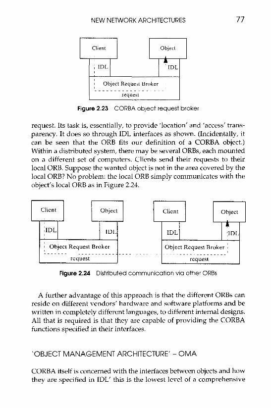
NEW NETWORK ARCHITECTURES
Client
: IDL
I Object Request Broker 1 ~I
77
Figure 2.23 CORBA object request broker
request. Its task is, essentially, to provide ’location’ and ’access’ trans- parency. It does so through IDL interfaces as shown. (Incidentally, it can be seen that the ORB fits our definition of a CORBA object.) Within a distributed system, there may be several ORBs, each mounted on a different set of computers. Clients send their requests to their local ORB. Suppose the wanted object is not in the area covered by the local ORB? No problem: the local ORB simply communicates with the object’s local ORB as in Figure 2.24.
Client Object Client Object
I
~ I D L A
IDL :IDL IDL
I Object Request Broker Object Request Broker I I
--------------------____________________-----------.--
request
Figure 2.24 Distributed communication via other ORBS
request 1
A further advantage of this approach is that the different ORBs can reside on different vendors’ hardware and software platforms and be written in completely different languages, to different internal designs. All that is required is that they are capable of providing the CORBA functions specified in their interfaces.
‘OBJECT MANAGEMENT ARCHITECTURE’ - OMA
CORBA itself is concerned with the interfaces between objects and how they are specified in IDL’ this is the lowest level of a comprehensive
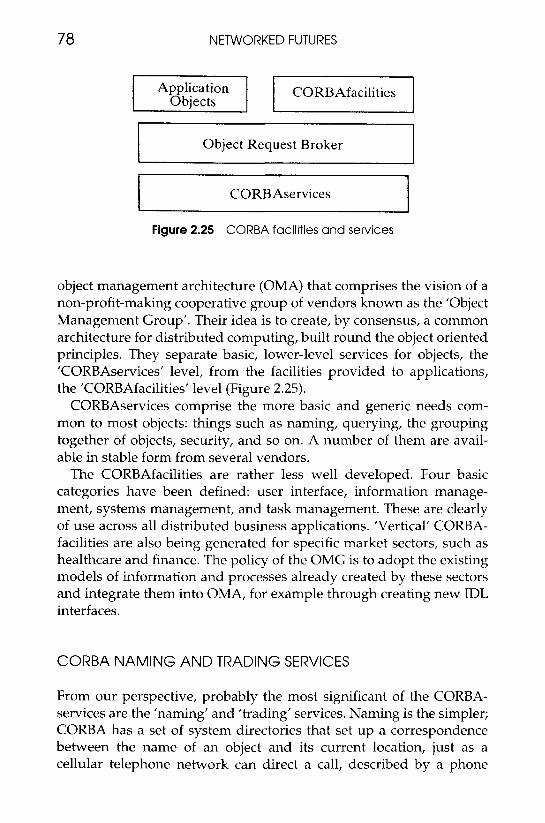
78 NETWORKED FUTURES
Application CORBAfacilities
~~~~~
Object Request Broker i
CORBAservices
Figure 2.25 CORBA facilities and services
object management architecture (OMA) that comprises the vision of a non-profit-making cooperative group of vendors known as the ‘Object Management Group’. Their idea is to create, by consensus, a common architecture for distributed computing, built round the object oriented principles. They separate basic, lower-level services for objects, the ’CORBAservices’ level, from the facilities provided to applications, the ‘CORBAfacilities’ level (Figure 2.25).
CORBAservices comprise the more basic and generic needs com- mon to most objects: things such as naming, querying, the grouping together of objects, security, and so on. A number of them are avail- able in stable form from several vendors.
The CORBAfacilities are rather less well developed. Four basic categories have been defined: user interface, information manage- ment, systems management, and task management. These are clearly of use across all distributed business applications. ’Vertical’ CORBA- facilities are also being generated for specific market sectors, such as healthcare and finance. The policy of the OMG is to adopt the existing models of information and processes already created by these sectors and integrate them into OMA, for example through creating new IDL interfaces.
CORBA NAMING AND TRADING SERVICES
From our perspective, probably the most significant of the CORBA- services are the ’naming’ and ’trading’ services. Naming is the simpler; CORBA has a set of system directories that set up a correspondence between the name of an object and its current location, just as a cellular telephone network can direct a call, described by a phone
NEW NETWORK ARCHITECTURES 79
number, to a specific aerial serving the cell in which the called party is currently present. (You simply use the name; the CORBA service maintains the path to the object.)
But that assumes you know who you want to call (and also, possibly, for what purpose and on what terms). Suppose you want to find out who can sell you a particular type of car, at what price and how soon. You need to look at a Yellow Pages directory that lists companies under the services you offer, and obtain a contact number. That is part of what a Trader service will do. It will allow you to identify sources of objects you require; these may, in the early days, be simple services such as an application to securely 'watermark' your data against copyright theft, but, in principle, it should be able to find you a list of virtual organisations that can remotely run human resource management software for your organisation, for example.
The Trader not only gives you the names of the suitable objects; it also gives you details of the services they offer - speed, cost, security policy and so on.
At this point it has to be said that some of the Trader properties have still to be defined by the OMG and most of the benefits of Trader services can only be postulated. Nevertheless, the basic concepts are widely known and CORBA is becoming widely used as a platform for advanced services.
CORBA LIMITATIONS AND ALTERNATIVES
CORBA is not the only solution proposed for distributed computing. Others such as the Distributed Computing Environment (DCE) from the Open Software Foundation approach the problem from slightly different angles. DCE, for instance, has a client-server approach. However, CORBA and the credible alternatives probably have a reasonably smooth migration path towards a common solution, given industry willingness. The issues that the computing industry tends to concentrate on are those of increasing functionality without incurring equivalent costs in application software development or complexity, and in meeting the need to operate across a heterogeneous collection of hardware and software. This is a rational approach, given that these are major problem areas, but there is always a danger that other important issues may not be addressed. For instance, CORBA does not yet really support the management of multimedia data streams, and relatively little consideration is given by the various architectures
80 NETWORKED FUTURES
to the role of low latency (end-to-end delay). The control of data across the network is, in general, very ’peripheral-centric’. Perform- ance and quality of service are not yet the primary concerns of the computer industry’s approach to distributed computing.
TELECOMMUNICATIONS ‘SERVICE’ ARCHITECTURES - TINA
Telecommunications organisations, on the other hand, whilst frequently criticised for their ponderous decision-making and the slowness of the rollout of new systems, can justifiably be proud of their comparative excellence in commitment to service quality and performance. Thus it is no surprise that they are concerned to con- struct network architectures from a basis of ’service’. The latest approach is a ’Telecommunications Networking Information Archi- tecture’ (TINA), driven by a consortium of telecommunications operators and equipment vendors (known as TINA-C). TINA is wider than the Intelligent Network concept described earlier; in particular, it recognises that the end-user and network-centred services can no longer be easily separated, nor can the network expect to control the specification and supply of peripheral equipment. Furthermore, with the ever-increasing complexity of services demanded of the network, it is not possible to decouple network and service management. For instance, if bit-rates can be purchased on demand, is this something that needs to be handled by a commercial, ’service-management’ system that bills for it immediately it commences, or an issue for a ’network management’ computer that enables the bit-rate provision? Clearly, it is an issue for them both.
TINA therefore recognises the need to consider things in terms of three different but interrelated architectures (Figure 2.26).
The approach is object-oriented, based heavily on the theoretical work of the International Organisation for Standardisation’s Refer- ence Model for Open Distributed Processing (ISO/RM-ODP), which also had a major influence on CORBA. The computational domain of the TINA architecture chooses to use the OMG IDL specification language, in common with CORBA. However, TINA lays much more emphasis on the ’stream interfaces’ that handle ’isochronous’ (that is, really real-time) flows of multimedia signals.
TINA is also much more detailed on the specification of network (that is, telecommunication network) resources and defines common classes of objects used by network services such as basic telephony,
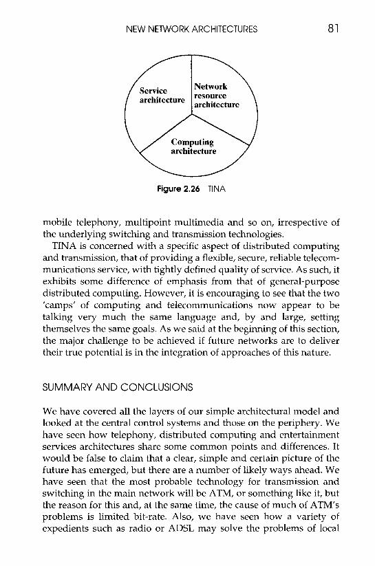
NEW NETWORK ARCHITECTURES 81
architecture
Figure 2.26 TINA
mobile telephony, multipoint multimedia and so on, irrespective of the underlying switching and transmission technologies.
TINA is concerned with a specific aspect of distributed computing and transmission, that of providing a flexible, secure, reliable telecom- munications service, with tightly defined quality of service. As such, it exhibits some difference of emphasis from that of general-purpose distributed computing. However, it is encouraging to see that the two ’camps’ of computing and telecommunications now appear to be talking very much the same language and, by and large, setting themselves the same goals. As we said at the beginning of this section, the major challenge to be achieved if future networks are to deliver their true potential is in the integration of approaches of this nature.
SUMMARY AND CONCLUSIONS
We have covered all the layers of our simple architectural model and looked at the central control systems and those on the periphery. We have seen how telephony, distributed computing and entertainment services architectures share some common points and differences. It would be false to claim that a clear, simple and certain picture of the future has emerged, but there are a number of likely ways ahead. We have seen that the most probable technology for transmission and switching in the main network will be ATM, or something like it, but the reason for this and, at the same time, the cause of much of ATM’s problems is limited bit-rate. Also, we have seen how a variety of expedients such as radio or ADSL may solve the problems of local
82 NETWORKED FUTURES
loop performance, at least for one-way traffic. In the next chapter we shall look at how optical fibre may alleviate the problem considerably. If this is so, and we no longer need to compromise on real-time operation versus cost, then many of the opposing viewpoints of the telecommunications and computing industries will disappear too. We note encouraging signs that the two industries are sharing a common outlook on higher-layer architectures for distributed information services. This is particularly important for the control-intensive services such as mobile telephony, which we cover later. A further trend is the significant redistribution of control from the centre to the periphery, brought about by the exponential growth in computing power.