network layer4-1 reti di calcolatori e sicurezza -- network layer --- part of these slides are...
TRANSCRIPT

Network Layer 4-1
Reti di calcolatori e Sicurezza-- Network Layer ---
Part of these slides are adapted from the slides of the book:Computer Networking: A Top Down Approach Featuring the Internet,
2nd edition. Jim Kurose, Keith Ross
Addison-Wesley, July 2002. (copyright 1996-2002
J.F Kurose and K.W. Ross, All Rights Reserved)

Network Layer 4-2
Chapter 4: Network LayerChapter goals: understand principles
behind network layer services: routing (path
selection) dealing with scale how a router works advanced topics: IPv6,
mobility instantiation and
implementation in the Internet
Overview: network layer services routing principles: path
selection (seminario) hierarchical routing
(seminario) IP Internet routing protocols
reliable transfer (seminario) intra-domain inter-domain
what’s inside a router? IPv6 (seminario) Mobility (seminario)

Network Layer 4-3
Chapter 4 roadmap
4.1 Introduction and Network Service Models4.2 Routing Principles4.3 Hierarchical Routing4.4 The Internet (IP) Protocol4.5 Routing in the Internet4.6 What’s Inside a Router4.7 IPv64.8 Multicast Routing4.9 Mobility

Network Layer 4-4
Network: Funzionalità
Trasportare pacchetti (datagram) dal sender al receiver
I protocolli del livello network “girano” sia sugli host che sui router
Funzionalità principali: Determinazione del percorso
dei pacchetti:. Routing Switching: funzione che
definisce le modalità di input/output dei pacchetti in un router
Call setup: attività di inizializzazione del percorso (solo in alcune architteture) (NO IP! .. Ma con QoS?)
networkdata linkphysical
networkdata linkphysical
networkdata linkphysical
networkdata linkphysical
networkdata linkphysical
networkdata linkphysical
networkdata linkphysical
networkdata linkphysical
application
transportnetworkdata linkphysical
application
transportnetworkdata linkphysical

Network Layer 4-5
Il modello del servizio
Quale è il modello di servizio offerto dal livello network?
Viene assicurata una determinata banda di trasmissione?
loss-free delivery? in-order delivery? congestion feedback?
? ??virtual circuit
-- datagram
Due risposte possibili
Serv
izi di re
te

Network Layer 4-6
Circuiti Virtuali
call setup: per ogni attivazione del circuto prima di poter trasmettere dati
Ogni pacchetto trasmesso deve avere un tag di identificazione del circuito (non importa l’indirizzo di destinazione)
“il cammino che viene stabilito tra il sender ed il receiver fornisce un comporta di tipo telefonico (a commutazione di circuito)”
Network Layer 4-7
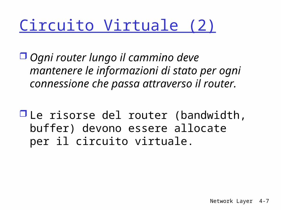
Circuito Virtuale (2)
Ogni router lungo il cammino deve mantenere le informazioni di stato per ogni connessione che passa attraverso il router.
Le risorse del router (bandwidth, buffer) devono essere allocate per il circuito virtuale.

Network Layer 4-8
Circuito Virtuale (3)
Comportamento ideale di un circuto virtuale
application
transportnetworkdata linkphysical
application
transportnetworkdata linkphysical
1. Initiate call 2. incoming call
3. Accept call4. Call connected5. Data flow begins 6. Receive data

Network Layer 4-9
Circuito Virtuale (conclusioni)
Utilizzato in particolari applicazioni (ad esempio quando si vogliono avere dei collegamenti dedicati tra intranet aziendali)
ATM, frame-relay, X.25 utilizzano questo modello di servizio
Internet: no!!

Network Layer 4-10
Reti Datagram: Internet Nessuna azione di attivazione (call set up) router: non mantengono informazioni di stato sulle
connessioni Network: non esiste la nozione di “connessione”
I pacchetti sono caratterizzati dall’indirizzo di destinazione (pacchetti di una connessione possono seguire un percorso differente)
application
transportnetworkdata linkphysical
application
transportnetworkdata linkphysical
1. Send data 2. Receive data

Network Layer 4-11
Network:
NetworkArchitecture
Internet
ATM
ATM
ATM
ATM
ServiceModel
best effort
CBR
VBR
ABR
UBR
Bandwidth
none
constantrateguaranteedrateguaranteed minimumnone
Loss
no
yes
yes
no
no
Order
no
yes
yes
yes
yes
Timing
no
yes
yes
no
no
Congestionfeedback
no (inferredvia loss)nocongestionnocongestionyes
no
Guarantees ?

Network Layer 4-12
Datagram vs VC
Internet Scambio dei dati tra le
applicazioni Servizi “elastic” rispetto
ai requisiti temporali Host (computers)
Possono implementare politiche per il controllo della congestione, etc
Rete semplice ma applicazioni evolute
Eterogeneità: difficile prevedere una nozione uniforme di servizio
ATM Origine nella telefonia
Richiesta di affidabilità e grossi vincoli temporali
Host:terminali telefonici La rete è di fatto
complessa

Network Layer 4-13
Chapter 4 roadmap4.1 Introduction and Network Service Models4.2 Routing Principles
Link state routing Distance vector routing
4.3 Hierarchical Routing4.4 The Internet (IP) Protocol4.5 Routing in the Internet4.6 What’s Inside a Router4.7 IPv64.8 Multicast Routing4.9 Mobility

Network Layer 4-14
Routing
Graph abstraction for routing algorithms:
graph nodes are routers
graph edges are physical links link cost: delay, $
cost, or congestion level
Goal: determine “good” path
(sequence of routers) thru network from source to
dest.
Routing protocol
A
ED
CB
F
2
2
13
1
1
2
53
5
“good” path: typically means
minimum cost path other def’s possible

Network Layer 4-15
Caratteristiche del routing Switching vs Routing
Switching: attività che seleziona una porta del router in base alle informazioni della tabella di routing
routing: attività di costruzione della tabella di routing
Network Layer 4-16
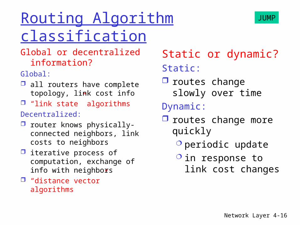
Routing Algorithm classification
Global or decentralized information?
Global: all routers have complete
topology, link cost info “link state” algorithmsDecentralized: router knows physically-
connected neighbors, link costs to neighbors
iterative process of computation, exchange of info with neighbors
“distance vector” algorithms
Static or dynamic?Static: routes change slowly
over timeDynamic: routes change more
quickly periodic update in response to link
cost changes
JUMP

Network Layer 4-17
A Link-State Routing Algorithm
Dijkstra’s algorithm net topology, link costs
known to all nodes accomplished via “link
state broadcast” all nodes have same
info computes least cost paths
from one node (‘source”) to all other nodes gives routing table for
that node iterative: after k iterations,
know least cost path to k dest.’s
Notation: c(i,j): link cost from node
i to j. cost infinite if not direct neighbors
D(v): current value of cost of path from source to dest. V
p(v): predecessor node along path from source to v, that is next v
N: set of nodes whose least cost path definitively known
Network Layer 4-18
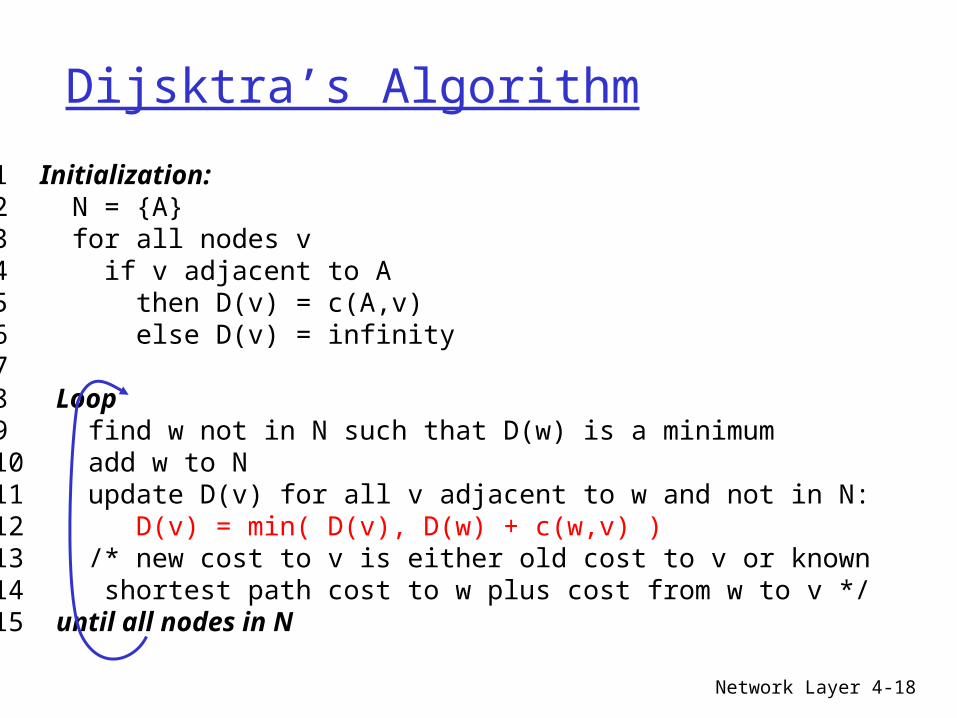
Dijsktra’s Algorithm
1 Initialization: 2 N = {A} 3 for all nodes v 4 if v adjacent to A 5 then D(v) = c(A,v) 6 else D(v) = infinity 7 8 Loop 9 find w not in N such that D(w) is a minimum 10 add w to N 11 update D(v) for all v adjacent to w and not in N: 12 D(v) = min( D(v), D(w) + c(w,v) ) 13 /* new cost to v is either old cost to v or known 14 shortest path cost to w plus cost from w to v */ 15 until all nodes in N

Network Layer 4-19
Dijkstra’s algorithm: example
Step012345
start NA
ADADE
ADEBADEBC
ADEBCF
D(B),p(B)2,A2,A2,A
D(C),p(C)5,A4,D3,E3,E
D(D),p(D)1,A
D(E),p(E)infinity
2,D
D(F),p(F)infinityinfinity
4,E4,E4,E
A
ED
CB
F
2
2
13
1
1
2
53
5

Network Layer 4-20
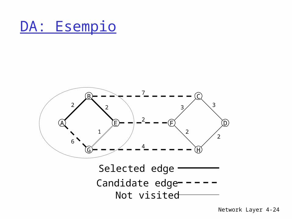
DA: Esempio
A
B
G
E F
C
H
D
7
4
2
2
4
1
2 3
2
3
2
Selected edge
Candidate edgeNot visited

Network Layer 4-21
DA: Esempio
A
B
G
E F
C
H
D
7
4
2
2
6
1
2 3
2
3
2
Selected edge
Candidate edgeNot visited

Network Layer 4-22
DA: Esempio
A
B
G
E F
C
H
D
7
4
2
2
6
1
2 3
2
3
2
Selected edge
Candidate edgeNot visited

Network Layer 4-23
DA: Esempio
A
B
G
E F
C
H
D
7
4
2
2
6
1
2 3
2
3
2
Selected edge
Candidate edgeNot visited
Network Layer 4-24
DA: Esempio
A
B
G
E F
C
H
D
7
4
2
2
6
1
2 3
2
3
2
Selected edge
Candidate edgeNot visited

Network Layer 4-25
Dijkstra’s algorithm, discussionAlgorithm complexity: n nodes each iteration: need to check all nodes, w, not in N n*(n+1)/2 comparisons: O(n**2) more efficient implementations possible: O(nlogn)
Oscillations possible: e.g., link cost = amount of carried traffic
A
D
C
B1 1+e
e0
e
1 1
0 0
A
D
C
B2+e 0
001+e1
A
D
C
B0 2+e
1+e10 0
A
D
C
B2+e 0
e01+e1
initially… recompute
routing… recompute … recompute

Network Layer 4-26
Distance Vector Routing Algorithm
iterative: continues until no
nodes exchange info. self-terminating: no
“signal” to stop
asynchronous: nodes need not
exchange info/iterate in lock step!
distributed: each node
communicates only with directly-attached neighbors
Distance Table data structure each node has its own row for each possible destination column for each directly-
attached neighbor to node example: in node X, for dest. Y
via neighbor Z:
D (Y,Z)X
distance from X toY, via Z as next hop
c(X,Z) + min {D (Y,w)}Z
w
=
=

Network Layer 4-27
Distance Table: example
A
E D
CB7
8
1
2
1
2
D ()
A
B
C
D
A
1
7
6
4
B
14
8
9
11
D
5
5
4
2
Ecost to destination via
dest
inat
ion
D (C,D)E
c(E,D) + min {D (C,w)}D
w== 2+2 = 4
D (A,D)E
c(E,D) + min {D (A,w)}D
w== 2+3 = 5
D (A,B)E
c(E,B) + min {D (A,w)}B
w== 8+6 = 14
loop!
loop!
Network Layer 4-28
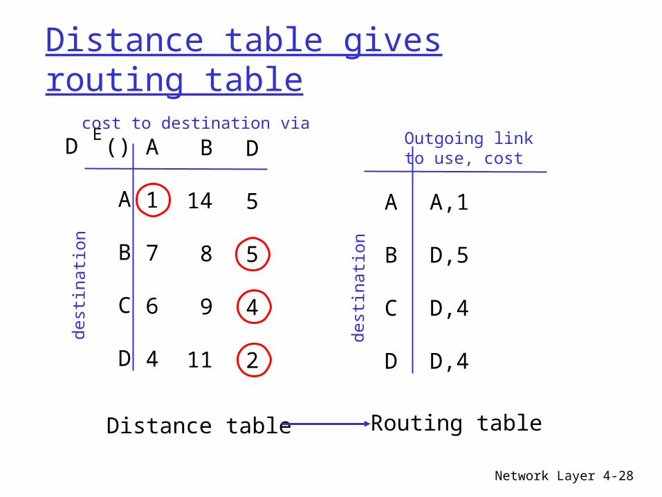
Distance table gives routing table
D ()
A
B
C
D
A
1
7
6
4
B
14
8
9
11
D
5
5
4
2
Ecost to destination via
dest
inat
ion
A
B
C
D
A,1
D,5
D,4
D,4
Outgoing link to use, cost
dest
inat
ion
Distance table Routing table

Network Layer 4-29
Routing: distribuito e asincrono
Algoritmo di Bellmann-Ford: vettore delle distanze (distance vector)

Network Layer 4-30
Distance Vector Routing: overview
Iterative, asynchronous: each local iteration caused by:
local link cost change message from neighbor:
its least cost path change from neighbor
Distributed: each node notifies
neighbors only when its least cost path to any destination changes neighbors then notify
their neighbors if necessary
wait for (change in local link cost of msg from neighbor)
recompute distance table
if least cost path to any dest
has changed, notify neighbors
Each node:

Network Layer 4-31
Distance Vector Algorithm:
1 Initialization: 2 for all adjacent nodes v: 3 D (*,v) = infinity /* the * operator means "for all rows" */ 4 D (v,v) = c(X,v) 5 for all destinations, y 6 send min D (y,w) to each neighbor /* w over all X's neighbors */
XX
Xw
At all nodes, X:

Network Layer 4-32
Distance Vector Algorithm (cont.):8 loop 9 wait (until I see a link cost change to neighbor V 10 or until I receive update from neighbor V) 11 12 if (c(X,V) changes by d) 13 /* change cost to all dest's via neighbor v by d */ 14 /* note: d could be positive or negative */ 15 for all destinations y: D (y,V) = D (y,V) + d 16 17 else if (update received from V wrt destination Y) 18 /* shortest path from V to some Y has changed */ 19 /* V has sent a new value for its min DV(Y,w) */ 20 /* call this received new value is "newval" */ 21 for the single destination y: D (Y,V) = c(X,V) + newval 22 23 if we have a new min D (Y,w)for any destination Y 24 send new value of min D (Y,w) to all neighbors 25 26 forever
w
XX
XX
X
w
w
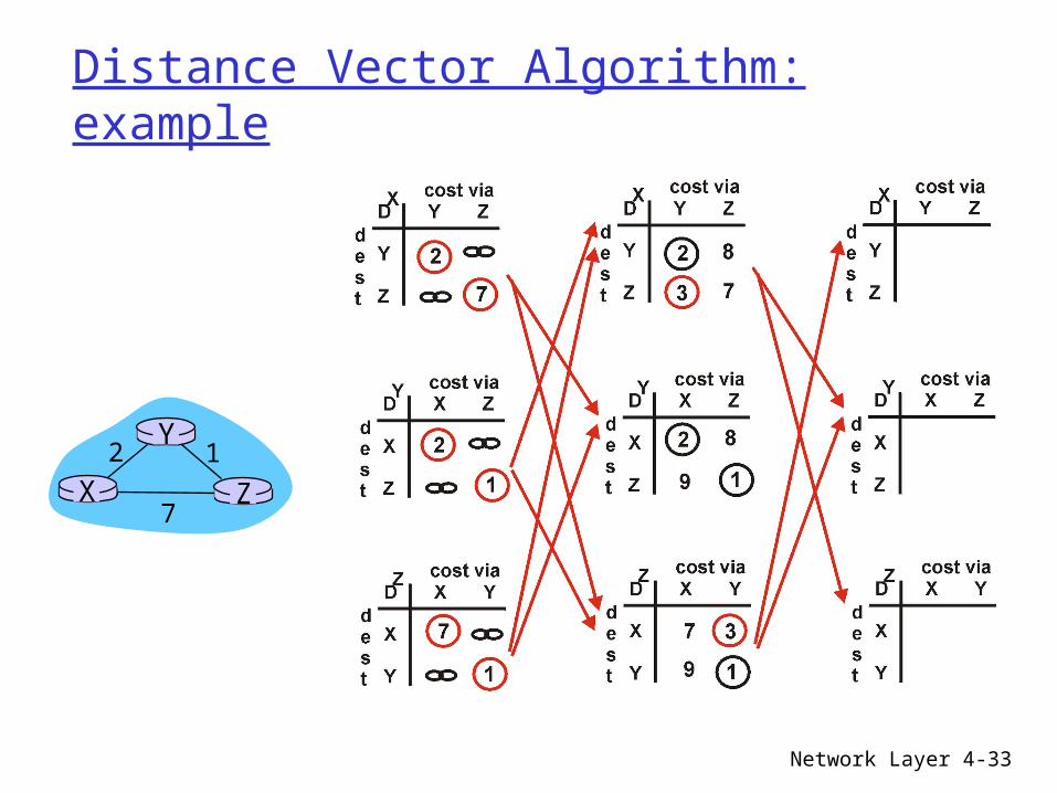
Network Layer 4-33
Distance Vector Algorithm: example
X Z12
7
Y

Network Layer 4-34
Distance Vector Algorithm: example
X Z12
7
Y
D (Y,Z)X
c(X,Z) + min {D (Y,w)}w=
= 7+1 = 8
Z
D (Z,Y)X
c(X,Y) + min {D (Z,w)}w=
= 2+1 = 3
Y

Network Layer 4-35
Distance Vector: link cost changes
Link cost changes: node detects local link cost
change updates distance table (line 15) if cost change in least cost path,
notify neighbors (lines 23,24)
X Z14
50
Y1
algorithmterminates“good
news travelsfast”
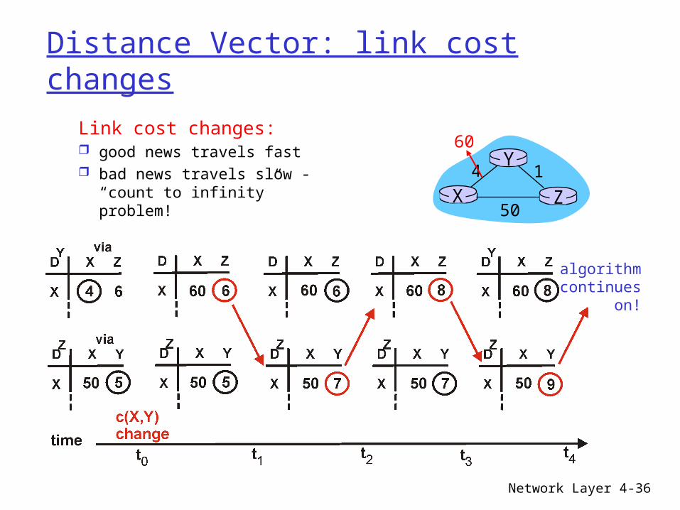
Network Layer 4-36
Distance Vector: link cost changes
Link cost changes: good news travels fast bad news travels slow -
“count to infinity” problem! X Z14
50
Y60
algorithmcontinues
on!

Network Layer 4-37
Distance Vector: poisoned reverse
If Z routes through Y to get to X : Z tells Y its (Z’s) distance to X is infinite (so
Y won’t route to X via Z) will this completely solve count to infinity
problem? X Z
14
50
Y60
algorithmterminates

Network Layer 4-38
Comparison of LS and DV algorithms
Message complexity LS: with n nodes, E links,
O(nE) msgs sent each DV: exchange between
neighbors only convergence time varies
Speed of Convergence LS: O(n2) algorithm requires
O(nE) msgs may have oscillations
DV: convergence time varies may be routing loops count-to-infinity problem
Robustness: what happens if router malfunctions?
LS: node can advertise
incorrect link cost each node computes only
its own table
DV: DV node can advertise
incorrect path cost each node’s table used by
others • error propagate thru
network

Network Layer 4-39
Chapter 4 roadmap
4.1 Introduction and Network Service Models4.2 Routing Principles4.3 Hierarchical Routing4.4 The Internet (IP) Protocol4.5 Routing in the Internet4.6 What’s Inside a Router4.7 IPv64.8 Multicast Routing4.9 Mobility

Network Layer 4-40
Routing
I meccanismi di routing che abbiamo studiato sono neccanismi ideali Rete è piatta Tutti i router sono identici
Buona astrazione ma … irrealistica!!!

Network Layer 4-41
InternetPassato recente
NSFNET backboneStanford
BARRNETregional
BerkeleyPARC
NCAR
UA
UNM
Westnetregional
UNL KU
ISU
MidNetregional…

Network Layer 4-42
Internet
Oggi
Backbone service provider
Peeringpoint
Peeringpoint
Large corporation
Large corporation
Smallcorporation
“Consumer ” ISP
“Consumer” ISP
“ Consumer” ISP

Network Layer 4-43
Internet
scalabilità: 50 milioni di possibili host:
Non possono memorizzare tutte le possibili destinazioni nella tabella di routing!
Messaggi per la modifica delle tabelle di routing avrebbero un costo troppo elevato!
Domini Amministrativi:
internet = rete di reti Ogni rete ha una sua
autorità (network admin) che ha il controllo complete sul proprio dominio

Network Layer 4-44
Routing Gerarchico
I router vengono aggregati in regioni: “autonomous systems” (AS)
I routers nella stessa AS eseguono lo stesso protocollo di routing “intra-AS” routing Router in regioni
differenti possono eseguire un protocollo diverso dal protocollo intra-AS routing
Router speciali in una AS
Eseguono il protocollo intra-AS routing con tutti gli altri router nella AS
Inoltre sono I responsabili del routing verso l’esterno della AS Eseguono un
protocollo inter-AS routing con gli altri gateway
gateway router

Network Layer 4-45
Intra-AS vs Inter-AS routing
Gateway:• inter-AS routing•intra-AS routing
inter-AS, intra-AS routing nel
gateway A.c
network layer
link layer
physical layer
a
b
b
aaC
A
Bd
A.a
A.c
C.bB.a
cb
c

Network Layer 4-46
Intra-AS vs Inter-AS routing
Host h2
a
b
b
aaC
A
Bd c
A.a
A.c
C.bB.a
cb
Hosth1
Intra-AS routingwithin AS A
Inter-AS routingbetween A and B
Intra-AS routingwithin AS B
Network Layer 4-47
Routing Gerarchico Rete viene suddivisa in regioni Router di una regione hanno informazione
completa su quella regione Analogia: Prefissi telefonici

Network Layer 4-48
Routing Gerarchico
Network Layer 4-49
Chapter 4 roadmap4.1 Introduction and Network Service Models4.2 Routing Principles4.3 Hierarchical Routing4.4 The Internet (IP) Protocol
4.4.1 IPv4 addressing 4.4.2 Moving a datagram from source to destination 4.4.3 Datagram format 4.4.4 IP fragmentation 4.4.5 ICMP: Internet Control Message Protocol 4.4.6 DHCP: Dynamic Host Configuration Protocol 4.4.7 NAT: Network Address Translation
4.5 Routing in the Internet4.6 What’s Inside a Router4.7 IPv64.8 Multicast Routing4.9 Mobility

Network Layer 4-50
The Internet Network layer
forwardingtable
Host, router network layer functions:
Routing protocols•path selection•RIP, OSPF, BGP
IP protocol•addressing conventions•datagram format•packet handling conventions
ICMP protocol•error reporting•router “signaling”
Transport layer: TCP, UDP
Link layer
physical layer
Networklayer

Network Layer 4-51
IP Addressing: introduction IP address: 32-bit
identifier for host, router interface
interface: connection between host/router and physical link router’s typically have
multiple interfaces host may have
multiple interfaces IP addresses
associated with each interface
223.1.1.1
223.1.1.2
223.1.1.3
223.1.1.4 223.1.2.9
223.1.2.2
223.1.2.1
223.1.3.2223.1.3.1
223.1.3.27
223.1.1.1 = 11011111 00000001 00000001 00000001
223 1 11

Network Layer 4-52
IP Addressing IP address:
network part (high order bits)
host part (low order bits)
What’s a network ? (from IP address perspective) device interfaces with
same network part of IP address
can physically reach each other without intervening router
223.1.1.1
223.1.1.2
223.1.1.3
223.1.1.4 223.1.2.9
223.1.2.2
223.1.2.1
223.1.3.2223.1.3.1
223.1.3.27
network consisting of 3 IP networks(for IP addresses starting with 223, first 24 bits are network address)
LAN

Network Layer 4-53
IP AddressingHow to find the
networks? Detach each
interface from router, host
create “islands of isolated networks
223.1.1.1
223.1.1.3
223.1.1.4
223.1.2.2223.1.2.1
223.1.2.6
223.1.3.2223.1.3.1
223.1.3.27
223.1.1.2
223.1.7.0
223.1.7.1223.1.8.0223.1.8.1
223.1.9.1
223.1.9.2
Interconnected system consisting
of six networks

Network Layer 4-54
IP Address Classes
Class A: For very large organizations 16 million hosts allowed
Class B: For large organizations 65 thousand hosts allowed
Class C For small organizations 255 hosts allowed
Class D Multicast addresses No network/host hierarchy

Network Layer 4-55
Indirizzamento per classe Proprietà
unico gerarchico: network + host
Dot Notation 10.3.2.4 128.96.33.81 192.12.69.77
Network Host
7 24
0A:
Network Host
14 16
1 0B:
Network Host
21 8
1 1 0C:

Network Layer 4-56
IP addressing: CIDR Indirizzamento via classi:
Uso poco efficiente dello spazio degli indirizzi: la classe B alloca indirizzi per 65K host anche se la rete ne richiede solamente 2k
CIDR: Classless InterDomain Routing Reti IP hanno indirizzi di lunghezza arbitraria formato: a.b.c.d/x, dove x è # di bit nella porzione
dell’indirizzo che definisce la rete.
11001000 00010111 00010000 00000000
networkpart
hostpart
200.23.16.0/23

Network Layer 4-57
Cammino di un datagram
IP datagram:
223.1.1.1
223.1.1.2
223.1.1.3
223.1.1.4 223.1.2.9
223.1.2.2
223.1.2.1
223.1.3.2223.1.3.1
223.1.3.27
A
BE
miscfields
sourceIP addr
destIP addr data
Datagram non viene modificato durante il percorso
Ruolo basilare degli indirizzi IP
Dest. Net. next router Nhops
223.1.1 1223.1.2 223.1.1.4 2223.1.3 223.1.1.4 2
RoutingTable@A

Network Layer 4-58
Cammino di un datagram
A::send IP-datagram @ B: lookup(IP(B)) nella tabella di
routing di A B è sulla stessa sottorete di A Call link.services
B e A sono connessi direttamente
Dest. Net. next router Nhops
223.1.1 1223.1.2 223.1.1.4 2223.1.3 223.1.1.4 2
miscfields223.1.1.1223.1.1.3data
223.1.1.1
223.1.1.2
223.1.1.3
223.1.1.4 223.1.2.9
223.1.2.2
223.1.2.1
223.1.3.2223.1.3.1
223.1.3.27
A
BE
RoutingTable@A

Network Layer 4-59
Cammino di un datagram
Dest. Net. next router Nhops
223.1.1 1223.1.2 223.1.1.4 2223.1.3 223.1.1.4 2
A:: send(datagram)@E: [email protected](E) E è un host di una rete
differente [email protected](
E) = 223.1.1.4 link invia il datagram al
router 223.1.1.4 datagram arriva @
223.1.1.4 …..
miscfields223.1.1.1223.1.2.3 data
223.1.1.1
223.1.1.2
223.1.1.3
223.1.1.4 223.1.2.9
223.1.2.2
223.1.2.1
223.1.3.2223.1.3.1
223.1.3.27
A
BE
RoutingTable@A
Network Layer 4-60
Cammino di un datagram
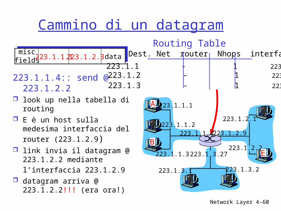
223.1.1.4:: send @ 223.1.2.2
look up nella tabella di routing
E è un host sulla medesima interfaccia del router (223.1.2.9)
link invia il datagram @ 223.1.2.2 mediante l’interfaccia 223.1.2.9
datagram arriva @ 223.1.2.2!!! (era ora!)
miscfields223.1.1.1223.1.2.3 data Dest. Net router Nhops interface
223.1.1 - 1 223.1.1.4 223.1.2 - 1 223.1.2.9
223.1.3 - 1 223.1.3.27
223.1.1.1
223.1.1.2
223.1.1.3
223.1.1.4 223.1.2.9
223.1.2.2
223.1.2.1
223.1.3.2223.1.3.1
223.1.3.27
A
BE
Routing Table

Network Layer 4-61
IP datagram format
ver length
32 bits
data (variable length,typically a TCP
or UDP segment)
16-bit identifier
Internet checksum
time tolive
32 bit source IP address
IP protocol versionnumber
header length (bytes)
max numberremaining hops
(decremented at each router)
forfragmentation/reassembly
total datagramlength (bytes)
upper layer protocolto deliver payload to
head.len
type ofservice
“type” of data flgsfragment
offsetupper layer
32 bit destination IP address
Options (if any) E.g. timestamp,record routetaken, specifylist of routers to visit.
how much overhead with TCP?
20 bytes of TCP 20 bytes of IP = 40 bytes + app
layer overhead

Network Layer 4-62
IPv4
Tipo del servizio: Differenza tra datagram di controllo e
datagram dei dati Router usano questo campo per
differenziare i livelli di servizio offerti TTL = 0 allora il datagram deve essere
abbandonato Protocol (simile al numero di porta del
trasporto) 6 => TCP 17 => UDP

Network Layer 4-63
Checksum
Perchè la suite TCP/IP (IPv4) prevede checksum sia al livello del trasporto che al livello della rete? Router non è richiesto fare questo calcolo TCP potrebbe basarsi su di un livello di
trasporto differente (esempio ATM)

Network Layer 4-64
MTU
Quantità di dati che può trasportare un protocollo del livello link è denominata MTU (max.transfer size): Link differenti possono avere, MTU distinte
• Ethernet MTU = 1500 bytes• WAN MTU = 576 bytes
Datagram è incapsulato all’interno di un pacchetto del link MTU limite alla dimensione del datagram

Network Layer 4-65
Problema
In un percorso sulla rete un datagram può passare lungo link che hanno una differente struttura del MTU
Soluzione: Frammentare i dati del datagram in piu’ datagram
Network Layer 4-66
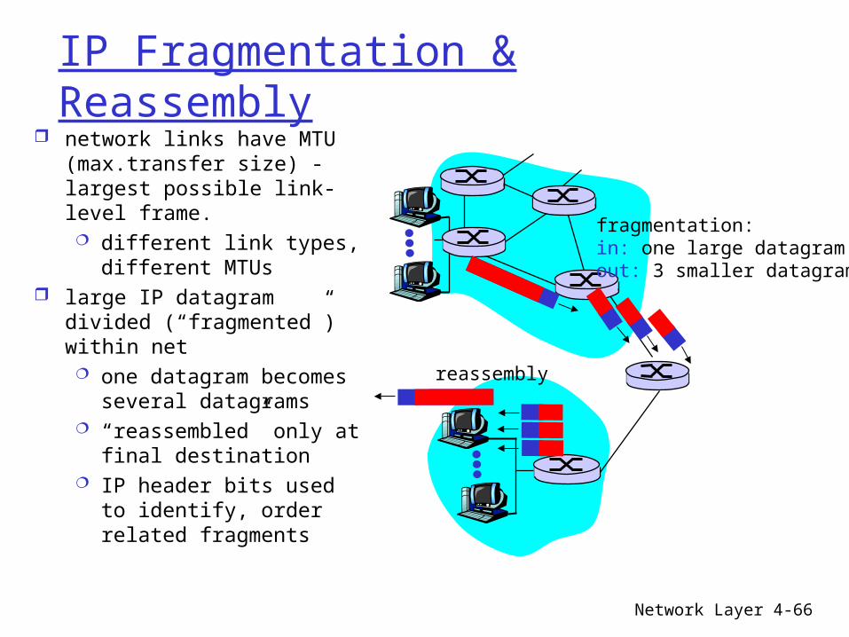
IP Fragmentation & Reassembly network links have MTU
(max.transfer size) - largest possible link-level frame. different link types,
different MTUs large IP datagram divided
(“fragmented”) within net one datagram becomes
several datagrams “reassembled” only at
final destination IP header bits used to
identify, order related fragments
fragmentation: in: one large datagramout: 3 smaller datagrams
reassembly

Network Layer 4-67
IP Fragmentation and Reassembly
ID=x
offset=0
fragflag=0
length=4000
ID=x
offset=0
fragflag=1
length=1500
ID=x
offset=1480
fragflag=1
length=1500
ID=x
offset=2960
fragflag=0
length=1040
One large datagram becomesseveral smaller datagrams
Example 4000 byte
datagram MTU = 1500 bytes

Network Layer 4-68
IP: Frammentazione & Riassemblaggio
F&R: Carico di lavoro sui router Piccola frammentazione
MTU almeno 576 bytes• MSS 536 bytes• 20 bytes = header del segmento• 20 bytes = header del datagram

Network Layer 4-69
Network ProtocolsICMP,
Network Layer 4-70
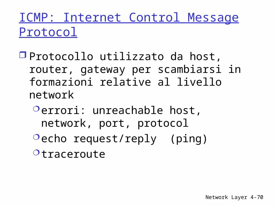
ICMP: Internet Control Message Protocol
Protocollo utilizzato da host, router, gateway per scambiarsi in formazioni relative al livello network errori: unreachable host, network,
port, protocolecho request/reply (ping)traceroute

Network Layer 4-71
ICMP: Internet Control Message Protocol
ICMP livello sopra IP: ICMP msgs sono
incapsulati in datagram IP
ICMP struttura dei messaggi: Campo type, Campo code Contengono inoltre
i primi 8 bytes del datagram IP che ha causato l’errore.
Type Code description0 0 echo reply (ping)3 0 dest. network unreachable3 1 dest host unreachable3 2 dest protocol unreachable3 3 dest port unreachable3 6 dest network unknown3 7 dest host unknown4 0 source quench (congestion control - not used)8 0 echo request (ping)9 0 route advertisement10 0 router discovery11 0 TTL expired12 0 bad IP header

Network Layer 4-72
ICMP: esempi di uso
Echo request reply Controllo se un host è ancora “vivo”
Address mask request/reply determinara subnet mask
Destination unreachable Indirizzo non valido
TTL expired … troppo lontano
Network Layer 4-73
Ping
ICMP echo request/reply Source sends ICMP echo request message to the
destination address Echo request packet contains sequence number and
timestamp Destination replies with an ICMP echo reply message
containing the data in the original echo request message
Source can calculate round trip time (RTT) of packets If no echo reply comes back then the destination is
unreachable

Network Layer 4-74
Ping (2)
R1 R2 R3A B
Tim
e
Echo request
Echo reply

Network Layer 4-75
Traceroute
Traceroute records the route that packets take A clever use of the TTL field When a router receives a packet, it decrements TTL If TTL=0, it sends an ICMP time exceeded message back
to the sender To determine the route, progressively increase TTL
Every time an ICMP time exceeded message is received, record the sender’s (router’s) address
Repeat until the destination host is reached or an error message occurs

Network Layer 4-76
Traceroute (2)
R1 R2 R3A B
TTL=1, Dest = B, port = invalid
TTL=2, Dest = B
TTL=3, Dest = B
TTL=4, Dest = B
Te (R1)
Te (R2)
Te (R3)
Pu (B)
Tim
e
Te = Time exceededPu = Port unreachable

Network Layer 4-77
Come si ottiene l’indirizzo IP?
Hosts File di configurazione
• Win: control-panel->network->configuration->tcp/ip->properties• Linux: /etc/rc.config
DHCP: Dynamic Host Configuration Protocol: ottiene l’indirizzo in modo dinamico: “plug-and-play”
• host broadcast “DHCP discover” msg• DHCP server risponde “DHCP offer” msg
– host invia la richiesta per IP address: “DHCP request” msg
• DHCP server invia l’indirizzo: “DHCP ack” msg

Network Layer 4-78
DHCP: Dynamic Host Configuration Protocol
Goal: allow host to dynamically obtain its IP address from network server when it joins networkCan renew its lease on address in use
Allows reuse of addresses (only hold address while connected an “on”
Support for mobile users who want to join network (more shortly)
DHCP overview: host broadcasts “DHCP discover” msg DHCP server responds with “DHCP offer” msg host requests IP address: “DHCP request” msg DHCP server sends address: “DHCP ack” msg

Network Layer 4-79
DHCP client-server scenario
223.1.1.1
223.1.1.2
223.1.1.3
223.1.1.4 223.1.2.9
223.1.2.2
223.1.2.1
223.1.3.2223.1.3.1
223.1.3.27
A
BE
DHCP server
arriving DHCP client needsaddress in thisnetwork

Network Layer 4-80
DHCP client-server scenarioDHCP server: 223.1.2.5 arriving
client
time
DHCP discover
src : 0.0.0.0, 68 dest.: 255.255.255.255,67yiaddr: 0.0.0.0transaction ID: 654
DHCP offer
src: 223.1.2.5, 67 dest: 255.255.255.255, 68yiaddrr: 223.1.2.4transaction ID: 654Lifetime: 3600 secs
DHCP request
src: 0.0.0.0, 68 dest:: 255.255.255.255, 67yiaddrr: 223.1.2.4transaction ID: 655Lifetime: 3600 secs
DHCP ACK
src: 223.1.2.5, 67 dest: 255.255.255.255, 68yiaddrr: 223.1.2.4transaction ID: 655Lifetime: 3600 secs

Network Layer 4-81
NAT: Network Address Translation
10.0.0.1
10.0.0.2
10.0.0.3
10.0.0.4
138.76.29.7
local network(e.g., home network)
10.0.0/24
rest ofInternet
Datagrams with source or destination in this networkhave 10.0.0/24 address for
source, destination (as usual)
All datagrams leaving localnetwork have same single source
NAT IP address: 138.76.29.7,different source port numbers

Network Layer 4-82
NAT: Network Address Translation
Motivation: local network uses just one IP address as far as outside word is concerned: no need to be allocated range of addresses from
ISP: - just one IP address is used for all devices can change addresses of devices in local network
without notifying outside world can change ISP without changing addresses of
devices in local network devices inside local net not explicitly
addressable, visible by outside world (a security plus).

Network Layer 4-83
NAT: Network Address Translation
Implementation: NAT router must:
outgoing datagrams: replace (source IP address, port #) of every outgoing datagram to (NAT IP address, new port #). . . remote clients/servers will respond using (NAT IP
address, new port #) as destination addr.
remember (in NAT translation table) every (source IP address, port #) to (NAT IP address, new port #) translation pair
incoming datagrams: replace (NAT IP address, new port #) in dest fields of every incoming datagram with corresponding (source IP address, port #) stored in NAT table
Network Layer 4-84
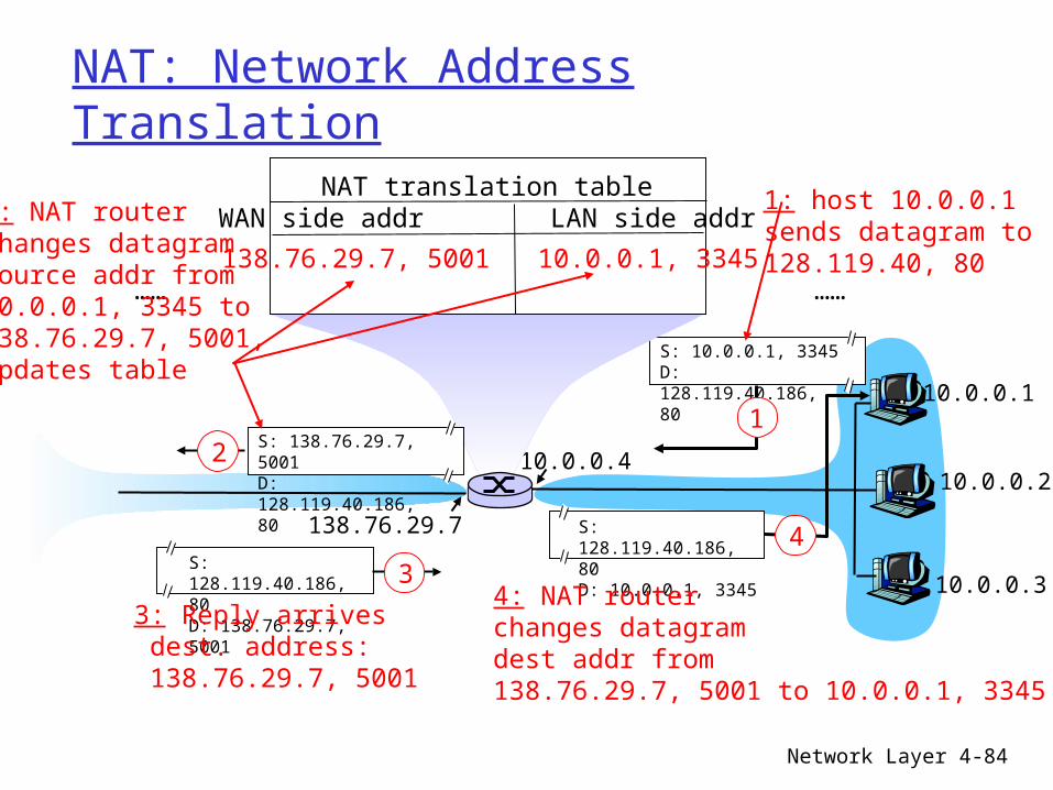
NAT: Network Address Translation
10.0.0.1
10.0.0.2
10.0.0.3
S: 10.0.0.1, 3345D: 128.119.40.186, 80
1
10.0.0.4
138.76.29.7
1: host 10.0.0.1 sends datagram to 128.119.40, 80
NAT translation tableWAN side addr LAN side addr
138.76.29.7, 5001 10.0.0.1, 3345…… ……
S: 128.119.40.186, 80 D: 10.0.0.1, 3345
4
S: 138.76.29.7, 5001D: 128.119.40.186, 80
2
2: NAT routerchanges datagramsource addr from10.0.0.1, 3345 to138.76.29.7, 5001,updates table
S: 128.119.40.186, 80 D: 138.76.29.7, 5001
3
3: Reply arrives dest. address: 138.76.29.7, 5001
4: NAT routerchanges datagramdest addr from138.76.29.7, 5001 to 10.0.0.1, 3345

Network Layer 4-85
NAT: Network Address Translation
16-bit port-number field: 60,000 simultaneous connections with a
single LAN-side address! NAT is controversial:
routers should only process up to layer 3 violates end-to-end argument
• NAT possibility must be taken into account by app designers, eg, P2P applications
address shortage should instead be solved by IPv6

Network Layer 4-86
Hierarchical addressing: route aggregation
“Send me anythingwith addresses beginning 200.23.16.0/20”
200.23.16.0/23
200.23.18.0/23
200.23.30.0/23
Fly-By-Night-ISP
Organization 0
Organization 7Internet
Organization 1
ISPs-R-Us“Send me anythingwith addresses beginning 199.31.0.0/16”
200.23.20.0/23Organization 2
...
...
Hierarchical addressing allows efficient advertisement of routing information:

Network Layer 4-87
Hierarchical addressing: more specific routes
ISPs-R-Us has a more specific route to Organization 1
“Send me anythingwith addresses beginning 200.23.16.0/20”
200.23.16.0/23
200.23.18.0/23
200.23.30.0/23
Fly-By-Night-ISP
Organization 0
Organization 7Internet
Organization 1
ISPs-R-Us“Send me anythingwith addresses beginning 199.31.0.0/16or 200.23.18.0/23”
200.23.20.0/23Organization 2
...
...
Network Layer 4-88
Chapter 4 roadmap4.1 Introduction and Network Service Models4.2 Routing Principles4.3 Hierarchical Routing4.4 The Internet (IP) Protocol4.5 Routing in the Internet
4.5.1 Intra-AS routing: RIP and OSPF 4.5.2 Inter-AS routing: BGP
4.6 What’s Inside a Router?4.7 IPv64.8 Multicast Routing4.9 Mobility
Network Layer 4-89
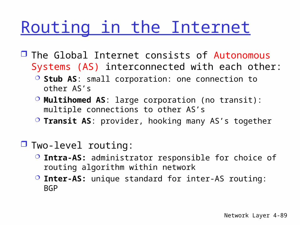
Routing in the Internet The Global Internet consists of Autonomous
Systems (AS) interconnected with each other: Stub AS: small corporation: one connection to other
AS’s Multihomed AS: large corporation (no transit): multiple
connections to other AS’s Transit AS: provider, hooking many AS’s together
Two-level routing: Intra-AS: administrator responsible for choice of routing
algorithm within network Inter-AS: unique standard for inter-AS routing: BGP

Network Layer 4-90
Internet AS HierarchyIntra-AS border (exterior gateway) routers
Inter-AS interior (gateway) routers

Network Layer 4-91
Intra-AS Routing
Also known as Interior Gateway Protocols (IGP) Most common Intra-AS routing protocols:
RIP: Routing Information Protocol
OSPF: Open Shortest Path First
IGRP: Interior Gateway Routing Protocol (Cisco proprietary)

Network Layer 4-92
RIP ( Routing Information Protocol)
Distance vector algorithm Included in BSD-UNIX Distribution in 1982 Distance metric: # of hops (max = 15 hops)
Can you guess why?
Distance vectors: exchanged among neighbors every 30 sec via Response Message (also called advertisement)
Each advertisement: list of up to 25 destination nets within AS
Network Layer 4-93
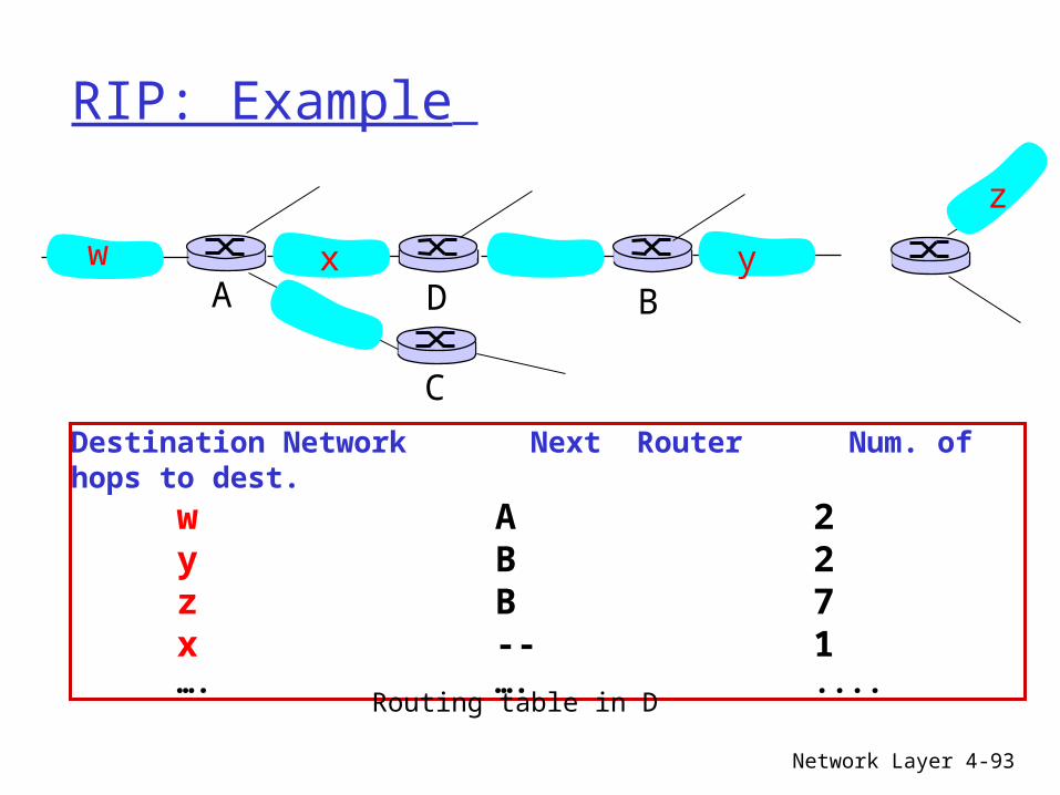
RIP: Example
Destination Network Next Router Num. of hops to dest. w A 2
y B 2 z B 7
x -- 1…. …. ....
w x y
z
A
C
D B
Routing table in D

Network Layer 4-94
RIP: Example
Destination Network Next Router Num. of hops to dest. w A 2
y B 2 z B A 7 5
x -- 1…. …. ....Routing table in D
w x y
z
A
C
D B
Dest Next hops w - - x - - z C 4 …. … ...
Advertisementfrom A to D

Network Layer 4-95
RIP: Link Failure and Recovery If no advertisement heard after 180 sec -->
neighbor/link declared dead routes via neighbor invalidated new advertisements sent to neighbors neighbors in turn send out new advertisements
(if tables changed) link failure info quickly propagates to entire net poison reverse used to prevent ping-pong
loops (infinite distance = 16 hops)

Network Layer 4-96
RIP Table processing
RIP routing tables managed by application-level process called route-d (daemon)
advertisements sent in UDP packets, periodically repeated
physical
link
network forwarding (IP) table
Transprt (UDP)
routed
physical
link
network (IP)
Transprt (UDP)
routed
forwardingtable

Network Layer 4-97
RIP Table example (continued)
Router: giroflee.eurocom.fr
Three attached class C networks (LANs) Router only knows routes to attached LANs Default router used to “go up” Route multicast address: 224.0.0.0 Loopback interface (for debugging)
Destination Gateway Flags Ref Use Interface -------------------- -------------------- ----- ----- ------ --------- 127.0.0.1 127.0.0.1 UH 0 26492 lo0 192.168.2. 192.168.2.5 U 2 13 fa0 193.55.114. 193.55.114.6 U 3 58503 le0 192.168.3. 192.168.3.5 U 2 25 qaa0 224.0.0.0 193.55.114.6 U 3 0 le0 default 193.55.114.129 UG 0 143454

Network Layer 4-98
OSPF (Open Shortest Path First)
“open”: publicly available Uses Link State algorithm
LS packet dissemination Topology map at each node Route computation using Dijkstra’s algorithm
OSPF advertisement carries one entry per neighbor router
Advertisements disseminated to entire AS (via flooding) Carried in OSPF messages directly over IP (rather than
TCP or UDP

Network Layer 4-99
OSPF “advanced” features (not in RIP)
Security: all OSPF messages authenticated (to prevent malicious intrusion)
Multiple same-cost paths allowed (only one path in RIP)
For each link, multiple cost metrics for different TOS (e.g., satellite link cost set “low” for best effort; high for real time)
Integrated uni- and multicast support: Multicast OSPF (MOSPF) uses same topology
data base as OSPF Hierarchical OSPF in large domains.

Network Layer 4-100
Hierarchical OSPF

Network Layer 4-101
Hierarchical OSPF
Two-level hierarchy: local area, backbone. Link-state advertisements only in area each nodes has detailed area topology; only know
direction (shortest path) to nets in other areas. Area border routers: “summarize” distances to
nets in own area, advertise to other Area Border routers.
Backbone routers: run OSPF routing limited to backbone.
Boundary routers: connect to other AS’s.

Network Layer 4-102
Inter-AS routing in the Internet: BGP
Figure 4.5.2-new2: BGP use for inter-domain routing
AS2 (OSPF
intra-AS routing)
AS1 (RI P intra-AS
routing) BGP
AS3 (OSPF intra-AS
routing)
BGP
R1 R2
R3
R4
R5

Network Layer 4-103
Internet inter-AS routing: BGP
BGP (Border Gateway Protocol): the de facto standard
Path Vector protocol: similar to Distance Vector protocol each Border Gateway broadcast to
neighbors (peers) entire path (i.e., sequence of AS’s) to destination
BGP routes to networks (ASs), not individual hosts
E.g., Gateway X may send its path to dest. Z:
Path (X,Z) = X,Y1,Y2,Y3,…,Z

Network Layer 4-104
Internet inter-AS routing: BGP
Suppose: gateway X send its path to peer gateway W W may or may not select path offered by X
cost, policy (don’t route via competitors AS), loop prevention reasons.
If W selects path advertised by X, then:Path (W,Z) = w, Path (X,Z)
Note: X can control incoming traffic by controlling it route advertisements to peers: e.g., don’t want to route traffic to Z -> don’t advertise any routes to
Z

Network Layer 4-105
BGP: controlling who routes to you
Figure 4.5-BGPnew: a simple BGP scenario
A
B
C
W X
Y
legend:
customer network:
provider network
A,B,C are provider networks X,W,Y are customer (of provider networks) X is dual-homed: attached to two networks
X does not want to route from B via X to C .. so X will not advertise to B a route to C

Network Layer 4-106
BGP: controlling who routes to you
Figure 4.5-BGPnew: a simple BGP scenario
A
B
C
W X
Y
legend:
customer network:
provider network
A advertises to B the path AW B advertises to W the path BAW Should B advertise to C the path BAW?
No way! B gets no “revenue” for routing CBAW since neither W nor C are B’s customers
B wants to force C to route to w via A B wants to route only to/from its customers!

Network Layer 4-107
BGP operation
Q: What does a BGP router do? Receiving and filtering route advertisements
from directly attached neighbor(s). Route selection.
To route to destination X, which path )of several advertised) will be taken?
Sending route advertisements to neighbors.

Network Layer 4-108
BGP messages
BGP messages exchanged using TCP. BGP messages:
OPEN: opens TCP connection to peer and authenticates sender
UPDATE: advertises new path (or withdraws old)
KEEPALIVE keeps connection alive in absence of UPDATES; also ACKs OPEN request
NOTIFICATION: reports errors in previous msg; also used to close connection

Network Layer 4-109
Why different Intra- and Inter-AS routing ?
Policy: Inter-AS: admin wants control over how its traffic
routed, who routes through its net. Intra-AS: single admin, so no policy decisions
needed
Scale: hierarchical routing saves table size, reduced
update trafficPerformance: Intra-AS: can focus on performance Inter-AS: policy may dominate over performance

Network Layer 4-110
Chapter 4 roadmap
4.1 Introduction and Network Service Models
4.2 Routing Principles4.3 Hierarchical Routing4.4 The Internet (IP) Protocol4.5 Routing in the Internet4.6 What’s Inside a Router?4.7 IPv64.8 Multicast Routing4.9 Mobility

Network Layer 4-111
Router Architecture Overview
Two key router functions: run routing algorithms/protocol (RIP, OSPF, BGP) switching datagrams from incoming to outgoing link
Network Layer 4-112
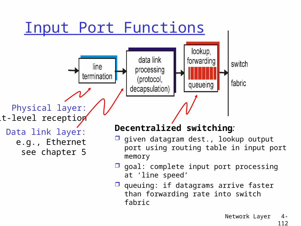
Input Port Functions
Decentralized switching: given datagram dest., lookup output
port using routing table in input port memory
goal: complete input port processing at ‘line speed’
queuing: if datagrams arrive faster than forwarding rate into switch fabric
Physical layer:bit-level reception
Data link layer:e.g., Ethernetsee chapter 5

Network Layer 4-113
Input Port Queuing
Fabric slower that input ports combined -> queueing may occur at input queues
Head-of-the-Line (HOL) blocking: queued datagram at front of queue prevents others in queue from moving forward
queueing delay and loss due to input buffer overflow!

Network Layer 4-114
Three types of switching fabrics
Network Layer 4-115
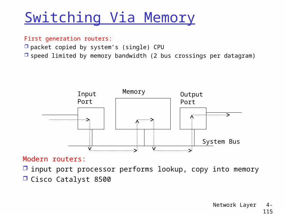
Switching Via MemoryFirst generation routers: packet copied by system’s (single) CPU speed limited by memory bandwidth (2 bus crossings per datagram)
InputPort
OutputPort
Memory
System Bus
Modern routers: input port processor performs lookup, copy into memory Cisco Catalyst 8500

Network Layer 4-116
Switching Via a Bus
datagram from input port memory
to output port memory via a shared bus
bus contention: switching speed limited by bus bandwidth
1 Gbps bus, Cisco 1900: sufficient speed for access and enterprise routers (not regional or backbone)

Network Layer 4-117
Switching Via An Interconnection Network
overcome bus bandwidth limitations Banyan networks, other interconnection nets
initially developed to connect processors in multiprocessor
Advanced design: fragmenting datagram into fixed length cells, switch cells through the fabric.
Cisco 12000: switches Gbps through the interconnection network

Network Layer 4-118
Output Ports
Buffering required when datagrams arrive from fabric faster than the transmission rate
Scheduling discipline chooses among queued datagrams for transmission

Network Layer 4-119
Output port queueing
buffering when arrival rate via switch exceeds output line speed
queueing (delay) and loss due to output port buffer overflow!

Network Layer 4-120
Chapter 4 roadmap
4.1 Introduction and Network Service Models
4.2 Routing Principles4.3 Hierarchical Routing4.4 The Internet (IP) Protocol4.5 Routing in the Internet4.6 What’s Inside a Router?4.7 IPv64.8 Multicast Routing4.9 Mobility

Network Layer 4-121
IPv6 Initial motivation: 32-bit address space
completely allocated by 2008. Additional motivation:
header format helps speed processing/forwarding
header changes to facilitate QoS new “anycast” address: route to “best” of
several replicated servers IPv6 datagram format:
fixed-length 40 byte header no fragmentation allowed
Network Layer 4-122
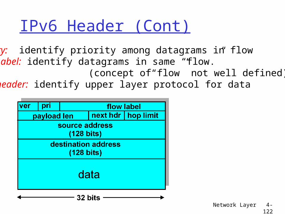
IPv6 Header (Cont)Priority: identify priority among datagrams in flowFlow Label: identify datagrams in same “flow.” (concept of“flow” not well defined).Next header: identify upper layer protocol for data

Network Layer 4-123
Other Changes from IPv4
Checksum: removed entirely to reduce processing time at each hop
Options: allowed, but outside of header, indicated by “Next Header” field
ICMPv6: new version of ICMP additional message types, e.g. “Packet Too
Big” multicast group management functions

Network Layer 4-124
Transition From IPv4 To IPv6
Not all routers can be upgraded simultaneous no “flag days” How will the network operate with mixed IPv4
and IPv6 routers? Two proposed approaches:
Dual Stack: some routers with dual stack (v6, v4) can “translate” between formats
Tunneling: IPv6 carried as payload in IPv4 datagram among IPv4 routers

Network Layer 4-125
Dual Stack Approach
A B E F
IPv6 IPv6 IPv6 IPv6
C D
IPv4 IPv4
Flow: XSrc: ADest: F
data
Flow: ??Src: ADest: F
data
Src:ADest: F
data
A-to-B:IPv6
Src:ADest: F
data
B-to-C:IPv4
B-to-C:IPv4
B-to-C:IPv6

Network Layer 4-126
TunnelingA B E F
IPv6 IPv6 IPv6 IPv6
tunnelLogical view:
Physical view:A B E F
IPv6 IPv6 IPv6 IPv6
C D
IPv4 IPv4
Flow: XSrc: ADest: F
data
Flow: XSrc: ADest: F
data
Flow: XSrc: ADest: F
data
Src:BDest: E
Flow: XSrc: ADest: F
data
Src:BDest: E
A-to-B:IPv6
E-to-F:IPv6
B-to-C:IPv6 inside
IPv4
B-to-C:IPv6 inside
IPv4

Network Layer 4-127
Chapter 4 roadmap
4.1 Introduction and Network Service Models
4.2 Routing Principles4.3 Hierarchical Routing4.4 The Internet (IP) Protocol4.5 Routing in the Internet4.6 What’s Inside a Router?4.7 IPv64.8 Multicast Routing4.9 Mobility

Network Layer 4-128
Multicast: one sender to many receivers Multicast: act of sending datagram to multiple
receivers with single “transmit” operation analogy: one teacher to many students
Question: how to achieve multicast
Multicast via unicast source sends N unicast
datagrams, one addressed to each of N receivers
multicast receiver (red)
not a multicast receiver (red)
routersforward unicastdatagrams

Network Layer 4-129
Multicast: one sender to many receivers Multicast: act of sending datagram to multiple
receivers with single “transmit” operation analogy: one teacher to many students
Question: how to achieve multicast
Network multicast Router actively participate in
multicast, making copies of packets as needed and forwarding towards multicast receivers
Multicastrouters (red) duplicate and forward multicast datagrams

Network Layer 4-130
Multicast: one sender to many receivers Multicast: act of sending datagram to multiple
receivers with single “transmit” operation analogy: one teacher to many students
Question: how to achieve multicast
Application-layer multicast end systems involved in
multicast copy and forward unicast datagrams among themselves

Network Layer 4-131
Internet Multicast Service Model
multicast group concept: use of indirection hosts addresses IP datagram to multicast group routers forward multicast datagrams to hosts
that have “joined” that multicast group
128.119.40.186
128.59.16.12
128.34.108.63
128.34.108.60
multicast group
226.17.30.197

Network Layer 4-132
Multicast groups class D Internet addresses reserved for multicast:
host group semantics:o anyone can “join” (receive) multicast groupo anyone can send to multicast groupo no network-layer identification to hosts of
members needed: infrastructure to deliver mcast-addressed
datagrams to all hosts that have joined that multicast group

Network Layer 4-133
Joining a mcast group: two-step process
local: host informs local mcast router of desire to join group: IGMP (Internet Group Management Protocol)
wide area: local router interacts with other routers to receive mcast datagram flow many protocols (e.g., DVMRP, MOSPF, PIM)
IGMPIGMP
IGMP
wide-areamulticast
routing

Network Layer 4-134
IGMP: Internet Group Management Protocol host: sends IGMP report when application joins
mcast group IP_ADD_MEMBERSHIP socket option host need not explicitly “unjoin” group when
leaving router: sends IGMP query at regular intervals
host belonging to a mcast group must reply to query
query report

Network Layer 4-135
IGMPIGMP version 1 router: Host
Membership Query msg broadcast on LAN to all hosts
host: Host Membership Report msg to indicate group membership randomized delay
before responding implicit leave via no
reply to Query
RFC 1112
IGMP v2: additions include
group-specific Query Leave Group msg
last host replying to Query can send explicit Leave Group msg
router performs group-specific query to see if any hosts left in group
RFC 2236
IGMP v3: under development as Internet draft

Multicast Routing: Problem Statement Goal: find a tree (or trees) connecting
routers having local mcast group members tree: not all paths between routers used source-based: different tree from each sender to rcvrs shared-tree: same tree used by all group members
Shared tree Source-based trees

Approaches for building mcast treesApproaches: source-based tree: one tree per source
shortest path trees reverse path forwarding
group-shared tree: group uses one tree minimal spanning (Steiner) center-based trees
…we first look at basic approaches, then specific protocols adopting these approaches

Shortest Path Tree
mcast forwarding tree: tree of shortest path routes from source to all receivers Dijkstra’s algorithm
R1
R2
R3
R4
R5
R6 R7
21
6
3 4
5
i
router with attachedgroup member
router with no attachedgroup member
link used for forwarding,i indicates order linkadded by algorithm
LEGENDS: source

Reverse Path Forwarding
if (mcast datagram received on incoming link on shortest path back to center)
then flood datagram onto all outgoing links else ignore datagram
rely on router’s knowledge of unicast shortest path from it to sender
each router has simple forwarding behavior:

Reverse Path Forwarding: example
• result is a source-specific reverse SPT– may be a bad choice with asymmetric links
R1
R2
R3
R4
R5
R6 R7
router with attachedgroup member
router with no attachedgroup member
datagram will be forwarded
LEGENDS: source
datagram will not be forwarded

Reverse Path Forwarding: pruning forwarding tree contains subtrees with no mcast
group members no need to forward datagrams down subtree “prune” msgs sent upstream by router with
no downstream group members
R1
R2
R3
R4
R5
R6 R7
router with attachedgroup member
router with no attachedgroup member
prune message
LEGENDS: source
links with multicastforwarding
P
P
P

Shared-Tree: Steiner Tree
Steiner Tree: minimum cost tree connecting all routers with attached group members
problem is NP-complete excellent heuristics exists not used in practice:
computational complexity information about entire network needed monolithic: rerun whenever a router needs
to join/leave
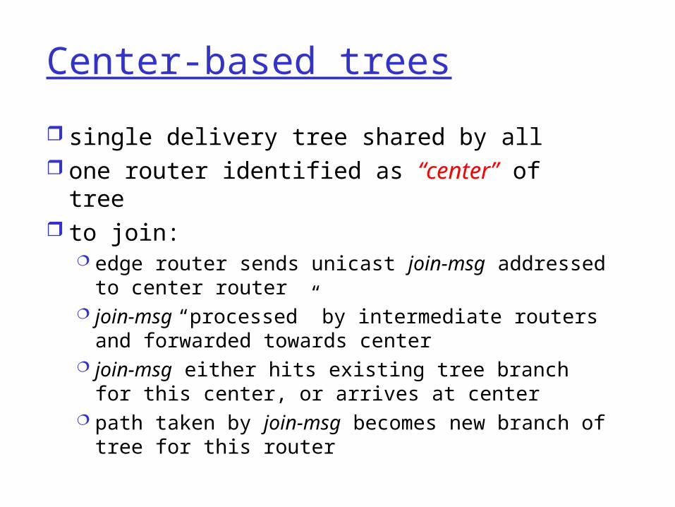
Center-based trees
single delivery tree shared by all one router identified as “center” of tree to join:
edge router sends unicast join-msg addressed to center router
join-msg “processed” by intermediate routers and forwarded towards center
join-msg either hits existing tree branch for this center, or arrives at center
path taken by join-msg becomes new branch of tree for this router
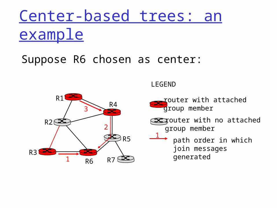
Center-based trees: an example
Suppose R6 chosen as center:
R1
R2
R3
R4
R5
R6 R7
router with attachedgroup member
router with no attachedgroup member
path order in which join messages generated
LEGEND
21
3
1

Internet Multicasting Routing: DVMRP
DVMRP: distance vector multicast routing protocol, RFC1075
flood and prune: reverse path forwarding, source-based tree RPF tree based on DVMRP’s own routing tables
constructed by communicating DVMRP routers no assumptions about underlying unicast initial datagram to mcast group flooded
everywhere via RPF routers not wanting group: send upstream
prune msgs

DVMRP: continued…
soft state: DVMRP router periodically (1 min.) “forgets” branches are pruned: mcast data again flows down unpruned branch downstream router: reprune or else continue
to receive data routers can quickly regraft to tree
following IGMP join at leaf odds and ends
commonly implemented in commercial routers Mbone routing done using DVMRP

Tunneling
Q: How to connect “islands” of multicast routers in a “sea” of unicast routers?
mcast datagram encapsulated inside “normal” (non-multicast-addressed) datagram
normal IP datagram sent thru “tunnel” via regular IP unicast to receiving mcast router
receiving mcast router unencapsulates to get mcast datagram
physical topology logical topology

PIM: Protocol Independent Multicast
not dependent on any specific underlying unicast routing algorithm (works with all)
two different multicast distribution scenarios :
Dense: group members
densely packed, in “close” proximity.
bandwidth more plentiful
Sparse: # networks with group
members small wrt # interconnected networks
group members “widely dispersed”
bandwidth not plentiful
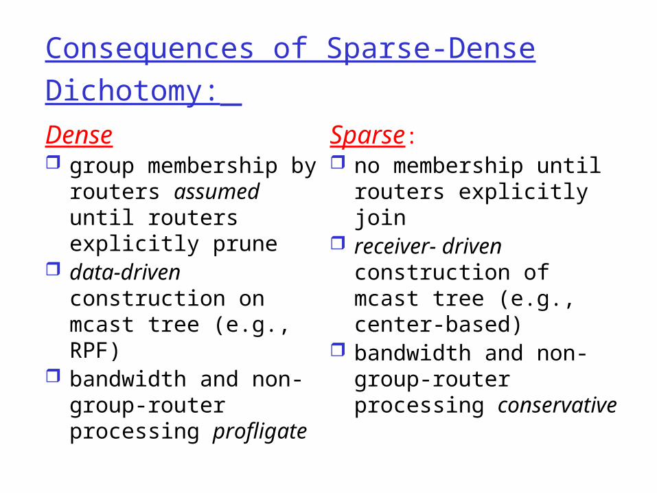
Consequences of Sparse-Dense Dichotomy: Dense group membership by
routers assumed until routers explicitly prune
data-driven construction on mcast tree (e.g., RPF)
bandwidth and non-group-router processing profligate
Sparse: no membership until
routers explicitly join receiver- driven
construction of mcast tree (e.g., center-based)
bandwidth and non-group-router processing conservative

PIM- Dense Mode
flood-and-prune RPF, similar to DVMRP but
underlying unicast protocol provides RPF info for incoming datagram
less complicated (less efficient) downstream flood than DVMRP reduces reliance on underlying routing algorithm
has protocol mechanism for router to detect it is a leaf-node router

PIM - Sparse Mode
center-based approach router sends join msg
to rendezvous point (RP) intermediate routers
update state and forward join
after joining via RP, router can switch to source-specific tree increased performance:
less concentration, shorter paths
R1
R2
R3
R4
R5
R6R7
join
join
join
all data multicastfrom rendezvouspoint
rendezvouspoint

PIM - Sparse Mode
sender(s): unicast data to RP,
which distributes down RP-rooted tree
RP can extend mcast tree upstream to source
RP can send stop msg if no attached receivers “no one is listening!”
R1
R2
R3
R4
R5
R6R7
join
join
join
all data multicastfrom rendezvouspoint
rendezvouspoint

Network Layer 4-153
Chapter 4 roadmap
4.1 Introduction and Network Service Models
4.2 Routing Principles4.3 Hierarchical Routing4.4 The Internet (IP) Protocol4.5 Routing in the Internet4.6 What’s Inside a Router?4.7 IPv64.8 Multicast Routing4.9 Mobility

Network Layer 4-154
What is mobility?
spectrum of mobility, from the network perspective:
no mobility high mobility
mobile user, usingsame access point
mobile user, passing through multiple access point while maintaining ongoing connections (like cell phone)
mobile user, connecting/ disconnecting from network using DHCP.

Network Layer 4-155
Mobility: Vocabularyhome network: permanent “home” of mobile(e.g., 128.119.40/24)
Permanent address: address in home network, can always be used to reach mobilee.g., 128.119.40.186
home agent: entity that will perform mobility functions on behalf of mobile, when mobile is remote
wide area network
correspondent

Network Layer 4-156
Mobility: more vocabulary
Care-of-address: address in visited network.(e.g., 79,129.13.2)
wide area network
visited network: network in which mobile currently resides (e.g., 79.129.13/24)
Permanent address: remains constant (e.g., 128.119.40.186)
home agent: entity in visited network that performs mobility functions on behalf of mobile.
correspondent: wants to communicate with mobile
Network Layer 4-157
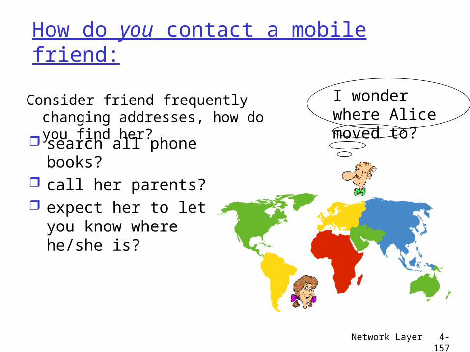
How do you contact a mobile friend:
search all phone books?
call her parents? expect her to let you
know where he/she is?
I wonder where Alice moved to?
Consider friend frequently changing addresses, how do you find her?

Network Layer 4-158
Mobility: approaches
Let routing handle it: routers advertise permanent address of mobile-nodes-in-residence via usual routing table exchange. routing tables indicate where each mobile
located no changes to end-systems
Let end-systems handle it: indirect routing: communication from
correspondent to mobile goes through home agent, then forwarded to remote
direct routing: correspondent gets foreign address of mobile, sends directly to mobile

Network Layer 4-159
Mobility: approaches
Let routing handle it: routers advertise permanent address of mobile-nodes-in-residence via usual routing table exchange. routing tables indicate where each mobile
located no changes to end-systems
let end-systems handle it: indirect routing: communication from
correspondent to mobile goes through home agent, then forwarded to remote
direct routing: correspondent gets foreign address of mobile, sends directly to mobile
not scalable
to millions of mobiles

Network Layer 4-160
Mobility: registration
End result: Foreign agent knows about mobile Home agent knows location of mobile
wide area network
home network
visited network
1
mobile contacts foreign agent on entering visited network
2
foreign agent contacts home agent home: “this mobile is resident in my network”

Network Layer 4-161
Mobility via Indirect Routing
wide area network
homenetwork
visitednetwork
3
2
41
correspondent addresses packets using home address of mobile
home agent intercepts packets, forwards to foreign agent
foreign agent receives packets, forwards to mobile
mobile replies directly to correspondent

Network Layer 4-162
Indirect Routing: comments Mobile uses two addresses:
permanent address: used by correspondent (hence mobile location is transparent to correspondent)
care-of-address: used by home agent to forward datagrams to mobile
foreign agent functions may be done by mobile itself triangle routing: correspondent-home-network-
mobile inefficient when correspondent, mobile are in same network

Network Layer 4-163
Forwarding datagrams to remote mobile
Permanent address: 128.119.40.186
Care-of address: 79.129.13.2
dest: 128.119.40.186
packet sent by correspondent
dest: 79.129.13.2 dest: 128.119.40.186
packet sent by home agent to foreign agent: a packet within a packet
dest: 128.119.40.186
foreign-agent-to-mobile packet
Network Layer 4-164
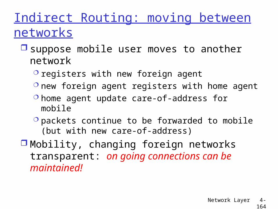
Indirect Routing: moving between networks suppose mobile user moves to another
network registers with new foreign agent new foreign agent registers with home agent home agent update care-of-address for mobile packets continue to be forwarded to mobile
(but with new care-of-address) Mobility, changing foreign networks
transparent: on going connections can be maintained!

Network Layer 4-165
Mobility via Direct Routing
wide area network
homenetwork
visitednetwork
4
2
41correspondent requests, receives foreign address of mobile
correspondent forwards to foreign agent
foreign agent receives packets, forwards to mobile
mobile replies directly to correspondent
3

Network Layer 4-166
Mobility via Direct Routing: comments
overcome triangle routing problem non-transparent to correspondent:
correspondent must get care-of-address from home agent What happens if mobile changes networks?

Network Layer 4-167
Mobile IP
RFC 3220 has many features we’ve seen:
home agents, foreign agents, foreign-agent registration, care-of-addresses, encapsulation (packet-within-a-packet)
three components to standard: agent discovery registration with home agent indirect routing of datagrams

Network Layer 4-168
Mobile IP: agent discovery agent advertisement: foreign/home agents
advertise service by broadcasting ICMP messages (typefield = 9)
RBHFMGV bits reserved
type = 16
type = 9 code = 0 = 9
checksum = 9
router address
standard ICMP fields
mobility agent advertisement
extension
length sequence #
registration lifetime
0 or more care-of-addresses
0 8 16 24
R bit: registration required
H,F bits: home and/or foreign agent
Network Layer 4-169
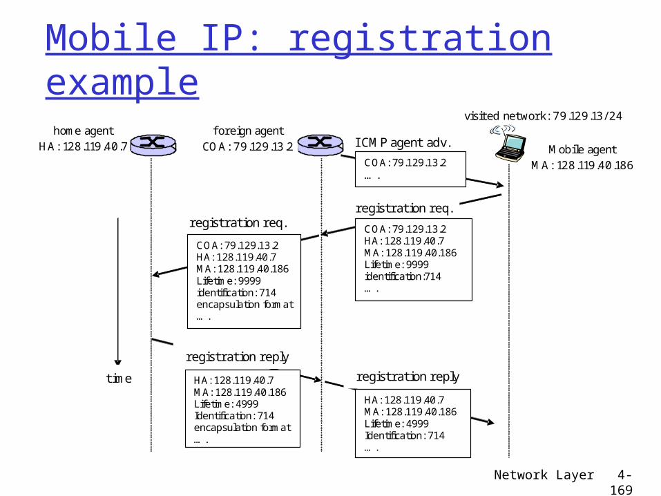
Mobile IP: registration example
visited network: 79.129.13/ 24 home agent
HA: 128.119.40.7 f oreign agent
COA: 79.129.13.2 COA: 79.129.13.2
….
I CMP agent adv. Mobile agent MA: 128.119.40.186
registration req.
COA: 79.129.13.2 HA: 128.119.40.7 MA: 128.119.40.186 Lifetime: 9999 identification:714 ….
registration req.
COA: 79.129.13.2 HA: 128.119.40.7 MA: 128.119.40.186 Lifetime: 9999 identification: 714 encapsulation format ….
registration reply
HA: 128.119.40.7 MA: 128.119.40.186 Lifetime: 4999 Identification: 714 encapsulation format ….
registration reply
HA: 128.119.40.7 MA: 128.119.40.186 Lifetime: 4999 Identification: 714 ….
time

Network Layer 4-170
Network Layer: summary
Next stop: the Data
link layer!
What we’ve covered: network layer services routing principles: link state
and distance vector hierarchical routing IP Internet routing protocols RIP,
OSPF, BGP what’s inside a router? IPv6 mobility