network features - cisco.com · † itu-t recommendation e.164, the international public...
TRANSCRIPT

Cisco BTS 10200 Softswitch NetworkOL-15337-11
C H A P T E R 1
Network FeaturesRevised: March 24, 2011, OL-15337-11
IntroductionThe Cisco BTS 10200 Softswitch supports network features as described in the following sections:
• Interoperability
• Numbering Plans and Dialing Procedures (includes information on digit manipulation, E.164 dialing plan, casual dialing (dial around), dial 1 options, directory services, easily recognizable codes, Information service calls (900 and 976), n11 support (211, 311, 411, 511, 611, 711, 811). and NRUF reporting)
• Emergency Services (911)
• Operator Services (includes information on Busy Line Verification and Operator Interrupt)
• SIP Triggers
• 8XX (Toll-Free Calling)
• Active Call Information Display
• Alerting Notification to Third-Party Feature Server
• Calling Party Number Options for Outbound SETUP Messages
• Dialing Parity (IntraLATA Toll Presubscription)
• Local Number Portability (LNP)
• Trunk and Line Testing
• Sh Interface
In general, BTS 10200 features delivered by gateway clients behave identically to their public switched telephone network (PSTN) counterparts.
Note For information on the hostage negotiation (HN) feature, see the “Hostage Negotiation” section on page 3-66.
1-1 and Subscriber Feature Descriptions, Release 6.0.x

Chapter 1 Network FeaturesInteroperability
Note For lawful intercept and CALEA, see Chapter 2, “Lawful Intercept and Enhanced CALEA Features.” For subscriber features, see Chapter 3, “Subscriber Features.” For outgoing call restrictions see Chapter 4, “Class of Service Restrictions and Outgoing Call Barring Features.”
Some features can be accessed and controlled by the subscriber using a handset and vertical service codes (VSCs). VSCs are provisionable by the service provider, and the customary values are country specific. The VSC values used throughout this chapter are for illustration purposes. For convenience, some VSC values are preprovisioned in the BTS 10200. The valid formats for VSC ASCII strings are listed in the VSC table in the Cisco BTS 10200 Softswitch CLI Database. To view the current VSC values provisioned on your system, use the show vsc CLI command. To provision VSCs, see the VSC provisioning procedure in the Provisioning Guide.
Typically, the system responds to user handset actions by providing an appropriate announcement. However, if an announcement is not provisioned or cannot be played, an alternate tone (for example, a reorder tone) is played. Announcements are listed in the Provisioning Guide, and tones are listed in the Operations and Maintenance Guide.
InteroperabilityThe BTS 10200 interworks with a wide range of network elements (NEs), but there are certain limitations. we recommend that you keep the following caution in mind as you prepare to purchase and use NEs for your network.
Caution Some features involve the use of other network elements (NEs) deployed in the service provider network, for example, gateways, media servers, announcement servers, eMTAs, and SIP phones. See the “Component Interoperability” section of the Release Notes for a complete list of the specific peripheral platforms, functions, and software loads that have been used in system testing for interoperability with the BTS 10200 Release 6.0.1 software. Earlier or later releases of platform software might be interoperable, and it might be possible to use other functions on these platforms. The list in the Release Notes certifies only that the required interoperation of these platforms, the functions listed, and the protocols listed have been successfully tested with the BTS 10200.
Numbering Plans and Dialing ProceduresThe BTS 10200 supports the numbering plans and dialing procedures listed in Table 1-1. These features are described in the sections that follow.
Note For additional details on the rules used in the numbering plans and dialing procedures, see the Routing and Dial Plan Guide.
1-2Cisco BTS 10200 Softswitch Network and Subscriber Feature Descriptions, Release 6.0.x
OL-15337-11

Chapter 1 Network FeaturesNumbering Plans and Dialing Procedures
Digit ManipulationThe digit manipulation (DIGMAN) feature allows you to modify both calling number and called number for both incoming and outgoing calls within the BTS 10200.
Tip The calling party number is also known as ANI (automatic number identification). The called party number is also known as DNIS (dialed number identification service).
You can use the DIGMAN feature to modify the nature of address (NOA) of ANI and/or DNIS numbers. This feature provides the following benefits in the service provider network:
• Dial plans for both North American Numbering Plan (NANP) and ITU-T E.164 numbering plan
• Flexible call processing
• ANI- or DNIS-based routing
For additional standards information, see the following industry sources:
• NANP—See http://www.nanpa.com
• ITU-T Recommendation E.164, The International Public Telecommunication Numbering Plan
The BTS 10200 performs digit manipulation by matching and replacing digits in the digit string that is being processed.
E.164 Dialing Plan ImplementationThe BTS 10200 implements a dialing plan based on ITU-T Recommendation E.164, The International Public Telecommunication Numbering Plan, a standard for numbering and routing. This dialing plan uses a generic numbering scheme for number evaluation. The BTS 10200 performs digit manipulation on ANI data of the calling party, and on DNIS data of the called party.
Table 1-1 Support for Numbering Plans and Dialing Procedures
Feature Description Reference
Digit Manipulation —
E.164 Dialing Plan Implementation ITU-T Recommendation E.164
Casual Dialing (Dial Around) —
Dial 1 Options for Local, Toll, and InterLATA Calls —
Directory Services (411, 555-1212, and 0+ Listing Services) GR-532-COREFSD-30-17-0000
Easily Recognizable Codes GR-2892-CORESR-2275, Sec. 3.3
Information Service Calls (900 and 976) —
n11 support (211, 311, 411, 511, 611, 711, 811) GR-532-COREFSD-30-16-0000
NRUF Reporting for NANPA Audit Support —
1-3Cisco BTS 10200 Softswitch Network and Subscriber Feature Descriptions, Release 6.0.x
OL-15337-11
Chapter 1 Network FeaturesNumbering Plans and Dialing Procedures
National Number
In the E.164 numbering scheme, there are three parts to any national number (number that terminates within the country):
• National destination code (NDC)—Identifies a region of the country (1 to 6 digits, typically 3). Provisioning of the NDC is optional. Some countries do not use NDCs in the national number.
• Exchange code (EC)—Identifies an area served by a single central office (CO) switching facility (1 to 6 digits, typically 4).
• Dialing number (DN)—Identifies a subscriber line (1 to 4 digits, typically 4).
The combination [EC + DN] is called the subscriber number (SN).The combination [NDC + EC + DN], or [NDC + SN], is called the national number (NN).
[NDC + EC + DN] is interpreted as [NPA + NXX + XXXX] in NANP, where NPA (numbering plan area) = 200 to 999, NXX (office code) = 200 to 999, and XXXX = 0000 to 9999. The BTS 10200 applies the NANP interpretation if the NANP-DIAL-PLAN flag is set to Y (yes) in the DIAL-PLAN-PROFILE table.
A subscriber originates a call by dialing as follows:
• To place a call to a phone in the same EC (served by the same CO), dial the SN. In most cases, this is considered a local call.
• To place a call to a phone in another EC, but within the same region (same NDC), dial the SN. In most cases, this is considered a local toll call.
• To place a call to a phone in another region (different NDC), dial the national (trunk) prefix and the NN. The national prefix varies from country to country. In most cases, this type of call is considered a national toll call.
Examples of national prefixes include:
– 0 in China
– 1 and 0 within NANP
– 9 in Finland and Spain
– 16 in France
For countries that do not use NDCs, it is not necessary to provision any value for the NDC parameter in the BTS 10200.
International Number
The international number is the number dialed in one country to reach a subscriber in another. Each country is assigned a country code (CC). The international number is the combination [CC + NN], or [CC + NCD + EC + DN]. Table 1-2 lists several examples.
1-4Cisco BTS 10200 Softswitch Network and Subscriber Feature Descriptions, Release 6.0.x
OL-15337-11

Chapter 1 Network FeaturesNumbering Plans and Dialing Procedures
To place a call to a phone in another country, the caller must dial an international prefix and then the international number. Thus, the complete digit string to dial is [international prefix + CC + NN]. The international prefix varies from country to country. Examples of international prefixes include:
• 00 in China
Example of a call from China to Montreal: 00-1-514-870-xxxx
• 011, 01 in NANP
Example of a call from the United States to Bruxelles: 011-32-02-123-xxxx
In some countries, two or more international prefixes might be used
• To reach different groups of countries
• To reach countries within a group
Casual Dialing (Dial Around)Casual dialing, also known as dial around, is a feature that allows subscribers to make 101XXXX calls. In the BTS 10200 implementation, the digit map CLI command tokens provide the digit pattern. The digit pattern specifies all possible acceptable patterns. An example of a casual digit pattern is 1010321 or 1010220. The digit map table tells the media gateway (MGW) how to collect and report dialed digits to the Call Agent (CA). Subscribers can prefix their toll, interLATA, or international calls with 101XXXX. Casual dialing supports the following casual calls:
• 101XXXX + 0/1 + NPA + NXX-XXXX
• 101XXXX + 0/00
• 101XXXX + 011/01 + CC + NN
Dial 1 Options for Local, Toll, and InterLATA CallsThe service provider can provision the system to control the use of prefix 1 for specific types of calls and for specific subscribers. Local, toll, and interLATA call types can each be independently provisioned in the subscriber-profile table as follows:
• Require that the subscriber dials the number with a prefix 1—If the system is provisioned this way, and the caller attempts to dial the number without using a prefix 1, the system rejects the call and provides an appropriate announcement (Release Code 10).
Table 1-2 Examples of International Numbers
Country City CC NDC EC DN Group
Complete International Number
Belgium Bruxelles 32 02 123 xxxx 32-02-123-xxxx
China Chengdu 86 28 8293 xxxx 86-28-8293-xxxx
Germany Dusseldorf 49 211 12 xxxx 49-211-12-xxxx
Canada Montreal 1 514 870 xxxx 1-514-870-xxxx
United Kingdom
London 44 71 248 xxxx 44-71-248-xxxx
1-5Cisco BTS 10200 Softswitch Network and Subscriber Feature Descriptions, Release 6.0.x
OL-15337-11
Chapter 1 Network FeaturesNumbering Plans and Dialing Procedures
• Require that the subscriber dials the number without a prefix 1—If the system is provisioned this way, and the caller attempts to dial the number using a prefix 1, the system rejects the call and provides an appropriate announcement (Release Code 9).
• Allows the subscriber to dial the number with or without a prefix 1—Allow call processing to proceed whether a prefix 1 is dialed on not.
For service access code (SAC) calls such as 500, 700, 800, and 900, the user must dial the prefix 1. The flags LOCAL-PFX1-OPT, INTERLATA-PFX1-OPT, and TOLL-PFX1-OPT in the Subscriber table do not affect these types of calls.
For a list of the specific provisioning parameters, see the Subscriber Profile table in the Cisco BTS 10200 Softswitch CLI Database. For a complete list of release cause codes, see the appendix of the Provisioning Guide.
Directory Services (411, 555-1212, and 0+ Listing Services)The BTS 10200 supports the directory services access feature as specified in Telcordia document GR-532-CORE, LSSGR: Interface To Directory Assistance System (FSD 30-17-0000).
Directory services allows a subscriber to obtain the listed telephone number for a given name and address. The caller dials a specific service number to reach directory services, also referred to as directory assistance (DA). When a subscriber dials one of the following digit patterns, the BTS 10200 routes the call to the applicable directory services in the PSTN:
• 411 or 555-1212 (DA)
• 1+411, 1+555-1212 (toll DA)
• 1-NPA-555-1212 (mostly for out-of-town/state numbers)
• 1-8XX-555-1212 (toll-free numbers)
• 0+ listing services
The service to the caller can be provided manually by a live operator, automated by a voice or dual tone multifrequency (DTMF) recognition system, or by a combination of these. The volume level from an automated voice-response unit, however, should be comparable to that of a live operator. Different network operators can employ different systems in providing directory services.
A typical directory services request requires that the caller first give the name of the town and city. The caller then provides the name of the person or business that the caller wants to call, including the spelling of unusual names. Finally, the caller states if the request is for residence or business. Additional services include handling multiple requests made during the same call and automatic connection to the person (or business) the caller wants to call.
Easily Recognizable CodesThe BTS 10200 supports selected easily recognizable codes (ERCs), as described in document SR-2275, Telcordia Notes on the Network, Section 3.3. The supported ERCs are:
• 500 personal communications services (PCS)—See the Alliance for Telecommunications Industry Solutions (ATIS) document INC-95-0407-009, Personal Communication Services N00NXX. Code Assignment Guidelines, for a PCS description.
• 700 service access calls (SAC)—Range of codes used by interexchange carriers (IXCs) to provide services on the network.
1-6Cisco BTS 10200 Softswitch Network and Subscriber Feature Descriptions, Release 6.0.x
OL-15337-11

Chapter 1 Network FeaturesNumbering Plans and Dialing Procedures
• Toll-free service call features (8XX)—See the “8XX (Toll-Free Calling)” section on page 1-33 for a description.
• 900/976 information service calls—See the “Information Service Calls (900 and 976)” section on page 1-7 for a description.
Other Telcordia reference documents include:
• SR-2275, Telcordia Notes on the Network
• GR-2892-CORE, Switching and Signaling Generic Requirements for Toll-Free Service Using AIN
Information Service Calls (900 and 976)Information service calls (ISCs) provide a variety of announcement-related services on a national or local basis. There are two general categories of this service:
• Public announcement services (PAS)—Weather, sports, horoscope, and so forth
• Media-stimulated calling (MSC)—Telephone voting, radio station call-ins, and so forth
National calls are dialed as 1-900-xxx-xxxx and local calls are dialed as NPA-976-xxxx.
n11 support (211, 311, 411, 511, 611, 711, 811)
Note 911 service is covered in the “Emergency Services (911)” section on page 1-9.
This section describes BTS 10200 support for n11 services. The typical relationship between the n11 codes and the nature of dial (NOD) values is as follows.
For a complete list of NOD values, see the Nature of Dial command in the Cisco BTS 10200 Softswitch CLI Database. To view the current NOD values provisioned on your system, use the show nod CLI command.
For additional information on n11 calling, see the following industry documents:
• Telcordia document GR-352-CORE, LSSGR: Service Codes N11 (FSD 30-16-000)
• The NANPA web site, http://www.nanpa.com/number_resource_info
n11 Code NOD Value
211 INFO
311 NON-EMG
411 DA
511 TRAFFIC
611 REPAIR
711 RELAY
811 BUSINESS
1-7Cisco BTS 10200 Softswitch Network and Subscriber Feature Descriptions, Release 6.0.x
OL-15337-11

Chapter 1 Network FeaturesNumbering Plans and Dialing Procedures
Community Information and Referral Services (211)
The 211 service provides access to information from government service agencies and certain public charity groups.
Nonemergency Services (311)
Some city governments offer 311 service to provide nonemergency information to the community. The caller dials 311 and the Call Agent translates this to the closest nonemergency access office.
The BTS 10200 supports nonemergency services (311) for routing calls to a specified route type and identification. Routes for all nonemergencies (311) are allocated through the destination table by defining the call type (call-type=NON-EMG) and the routing information for the dialed digits.
Directory Assistance (411)
The 411 service provides directory assistance. See the “Directory Services (411, 555-1212, and 0+ Listing Services)” section on page 1-6.
Traffic and Transportation Information (511)
The 511 service provides access to information about local traffic conditions.
Repair Service (611)
The 611 service connects to the local telephone repair service (if the service provider offers this service).
Telecommunications Relay Services (711)
The 711 service provides access to telecommunications relay services (TRS).
Local Billing Services (811)
The 811 service connects to the local telephone billing office.
NRUF Reporting for NANPA Audit SupportNumbering Resource Utilization and Forecast (NRUF) reporting provides NANPA audit data based on provisioned values in the dn2subscriber table. For FCC-required NANPA audit compliance, the report input is NPANXX. In markets outside of NANPA, the input can be based on either the combination of the NDC and the EC, or just the EC.
The data for NRUF reporting is generated based on either the NDC or the EC. The service provider can use the report dn-summary command to generate the following reports:
• Report on all DNs belonging to a specific NDC and EC
• Report on a thousands group within a specific NDC and EC
1-8Cisco BTS 10200 Softswitch Network and Subscriber Feature Descriptions, Release 6.0.x
OL-15337-11

Chapter 1 Network FeaturesEmergency Services (911)
Emergency Services (911)The BTS 10200 supports emergency services (911) as specified in Telcordia document GR-529-CORE, LSSGR: Basic 911 Emergency Service (FSD 15-01-0000).
Other Telcordia reference documents include
• SR-4163, E9-1-1 Service Description
• GR-350-CORE, E911 Public Safety Answering Point: Interface Between a 1/1A ESS Switch and Customer Premises Equipment
Note For information on the hostage negotiation feature, see the “Hostage Negotiation” section on page 3-66.
This section covers the following topics:
• “Description” section on page 1-9
• “Important Provisioning Requirements” section on page 1-10
• “Feature Interactions” section on page 1-10
• “911 Overflow Announcement” section on page 1-11
• “Emergency 911 Trunk Connection Loss Alarm” section on page 1-11
• “Emergency Call Display” section on page 1-12
• “Emergency Callback” section on page 1-12
• “911 Ring Back” section on page 1-14
• “Feature Provisioning Commands” section on page 1-16
DescriptionThe digit string 911 is typically used in the United States. Other digit strings are used elsewhere in the world.
Emergency service is a public safety feature providing emergency call routing to a designated Emergency Service Bureau (ESB), normally called the public safety answering point (PSAP) in the United States. The 3-digit 911 number is assigned for public use in many areas of the United States and Canada for reporting an emergency and requesting emergency assistance. Depending on municipal requirements and procedures, an ESB attendant can transfer the call to the proper agency, collect and relay emergency information to the agency, or dispatch emergency aid directly for one or more participating agencies.
911 calls are location dependent and must be selectively routed to the appropriate PSAP depending on where the call originates. The routing process is part of the Enhanced 911 (E911) feature set and works as follows:
1. In the PSTN, the local serving end office routes the call to the designated E911 tandem for that serving area.
2. The E911 tandem then routes the call to the proper PSAP.
Once the caller is connected to the PSAP attendant, the PSAP system typically displays the caller’s directory number to the PSAP attendant. Additional data (such as the subscriber’s name, address and closest emergency response units) may also be retrieved from the local carrier automatic location identification (ALI) database and displayed to the PSAP attendant.
1-9Cisco BTS 10200 Softswitch Network and Subscriber Feature Descriptions, Release 6.0.x
OL-15337-11

Chapter 1 Network FeaturesEmergency Services (911)
The service provider can provision a flag for each subscriber to specify which number to send with emergency calls—the subscriber directory number or the subscriber billing number.
Special emergency functions can be provided via a channel-associated signaling (CAS) trunking gateway (TGW) that supports ESB trunks or emergency service line (ESL) trunks with MF signaling. Examples of special emergency functions include:
• Operator callback—Allows the PSAP to automatically ring back the caller.
• End-to-end called-party hold—The BTS 10200 keeps the connection active even if the caller goes on hook.
• Operator disconnect—Allows the PSAP to terminate the call even though the caller has not gone on hook.
For additional details on these functions see the “911 Ring Back” section on page 1-14.
Important Provisioning RequirementsService providers in the United States typically provision the Destination table with call-type=EMG for the digit string 911, and call-subtype=NONE (default), because 911 is a central dispatch point for all emergency, ambulance, fire, and police calls.
Caution On the BTS 10200, for a call to be considered an emergency, it must be provisioned as call-type EMG. If you are using separate DNs for ambulance, fire, and police service (typically applies to networks outside the United States), we strongly recommend that you provision these as call-type EMG and call-subtype <AMBULANCE or FIRE or POLICE> in the Destination table. This is the only way to be sure that they will be given all the treatment of the EMG call-type.
Depending on the region of the world, the provisionable timers might require different values, or might not be needed, and they can be turned off. The called-party control feature, typically used in the United States, can also be turned off. All other functions of the emergency number are the same as for the 911 feature.
You can make the emergency service feature available to all subscriber lines connected to a BTS 10200 by means of the default office service ID, or to all subscribers in a specific POP by means of the office service ID. See the “Office Service ID and Default Office Service ID” section on page 3-166 for a general description of this provisionable service.
Feature InteractionsThe following feature interactions apply to emergency calls (call-type=EMG):
• During a 911 call from a subscriber line, the call waiting (CW) and three-way calling (TWC) features are automatically disabled for the subscriber line.
• The following interactions occur when a Centrex subscriber invokes call hold (CHD) and places a call to an emergency number:
– When the emergency operator answers the call, a two-party call is active between the subscriber and the emergency operator. The on-hold party remains on hold.
– When the subscriber presses the Flash button or hookswitch, a three-way call is established among the subscriber, the emergency operator, and the previously on-hold party.
– It is not possible to place the emergency operator on hold.
1-10Cisco BTS 10200 Softswitch Network and Subscriber Feature Descriptions, Release 6.0.x
OL-15337-11
Chapter 1 Network FeaturesEmergency Services (911)
911 Overflow AnnouncementThe system plays an announcement when all circuits to the emergency center are busy and the emergency call cannot be completed to the emergency center. An example of an announcement for this feature is, “We are experiencing 911 difficulties. Please hang up and dial 0 to reach an operator for emergency assistance.” The announcement is applied when the announcement resource is available and applicable. For the specific cause code and announcement ID, see the “Release Cause Codes and Announcement IDs” section in the Provisioning Guide.
Emergency ANIA service provider can provision a flag for a subscriber to specify which caller ID number to send with emergency calls—the subscriber DN or the billing DN.
The Emergency ANI feature allows the service provider to provision Enhanced 911 (E911) specific number for subscribers, which may be different from subscriber directory number (DN) or the billing DN.
A 911 call is directed to a Public Safety Answering Point (PSAP), the specific PSAP being dependent on the location where the call originates. The routing process is part of the E911 feature set. For more information on the routing process and the E911 feature set, see the “Emergency Services” section of the Cisco BTS 10200 Softswitch Network and Subscriber Feature Descriptions Guide, Release 6.0.1.
When subscribers move between different rate centers but keep the same number, the address of the subscriber changes. Emergency calls made by the subscriber might not be supported by the current PSAP. This leads to incorrect PSAP call routing, and incorrect or non-existing address lookups. Therefore, any modification of the current subscriber numbers and flags associated with outbound caller ID in the subscriber table might result in incorrect routing of emergency calls.
Provisioning a separate emergency ANI-specific number ensures that the outbound caller ID number of the subscriber does not change when the subscriber moves to a different rate center. This also ensures that the call is routed to the correct PSAP and correct address of the subscriber is looked up.
For information on provisioning this feature, see the Cisco BTS 10200 Softswitch Provisioning Guide.
Emergency 911 Trunk Connection Loss AlarmThe BTS 10200 is capable of generating a critical alarm of when an emergency trunk resource becomes remotely or locally blocked. This alarm will be raised when any of the following events occurs:
• The gateway becomes unreachable.
• The emergency trunk termination is administratively made OOS through CLI commands on the BTS 10200.
• The emergency trunk termination is remotely or locally blocked.
This feature is applicable only to emergency trunks of type CAS, SS7 and ISDN. The EMERGENCY-TRUNK-GROUP token in the applicable trunk group table must be provisioned to support this feature. For CAS trunk groups, the E911 / EMERGENCY-TRUNK token must also be provisioned.
1-11Cisco BTS 10200 Softswitch Network and Subscriber Feature Descriptions, Release 6.0.x
OL-15337-11

Chapter 1 Network FeaturesEmergency Services (911)
Emergency Call DisplayThe Display Emergency Calls feature will provide a command line interface (CLI) command to display the count of all on-going emergency calls based on the call-type and trunk group. A query call-count command will display count of 911 on-going calls in the Cisco BTS 10200 system, based on call type and trunk groups designated as 911 trunk groups. The query call-count command is defined as follows:
query call-count call-type=emergency [emergency|police|ambulance|fire|all-emergency|all]; [tgn-id=xxxx]; [tg=an alphanumeric description of TG]
The call-type token is mandatory and can take values emergency, police, ambulance, fire, all-emergency, and all. The tgn-id and tg tokens are optional and if specified the call-count will be provided for the specified trunk group (TG) only. When the tgn-id and tg tokens are provided as part of command, they should be consistent for the same trunk group. If they are inconsistent, a failure message is displayed as output. When the tgn-id and tg is specified, the call count will include both in-bound and out-bound calls on the specified TG for the specified call-type.
Note In the call counts, the Cisco BTS 10200 includes all calls regardless of whether a call is answered or in the setup phase (transient or active).
The call-type emergency is defined as a 911 call in the United States. The call-types police, fire, and ambulance may not be applicable in United States, but the command has these options and output report will support these call types.
In a query call-count command execution, when emergency is specified in call-type field, the command response will display count for only call-type as emergency (EMG). In a query call-count command execution, when all-emergency is specified in call-type field, the command response will display counts for all emergency calls (emergency (911), police, fire and ambulance). In a query call-count command execution, when all is specified in call-type field, the command response will display counts for all active calls in the system. In a query call-count command execution, if tgn-id and tg (optional parameters) are also specified along with call type, then the call-count will be provided for that TG only in the command response. In a query call-count command execution, if the tgn-id and tg that are specified are invalid or inconsistent, the following error message will be displayed:
Invalid TGN ID: xxxxInvalid TG: [an alphanumeric description of TG]
In overload conditions, the query call-count command will be blocked.
Emergency Callback The Emergency Callback (ECB) feature allows public safety answering point (PSAP) numbers to call back a subscriber provisioned on the Cisco BTS 10200 Softswitch. The BTS 10200 treats these callbacks as special high-priority calls so that for the subscriber with an active PSAP call, all terminating features are disabled except Call Waiting (CW) and Call Forwarding Busy (CFB). The advantage of the ECB feature is that the BTS 10200 blocks all terminating services that could potentially interrupt a call from a PSAP line.
ECB is an office-based feature. The BTS 10200 provides ECB to any subscriber associated with an office service that has ECB.
ECB is available when you assign it to the office service ID, then add the PSAP line directory number (DN) to the emergency_number_list table per the instructions for the Emergency Number List table in the Cisco BTS 10200 CLI Database. The BTS 10200 then determines which incoming calls should be
1-12Cisco BTS 10200 Softswitch Network and Subscriber Feature Descriptions, Release 6.0.x
OL-15337-11
Chapter 1 Network FeaturesEmergency Services (911)
classified as ECB. The BTS 10200 first checks the list of DNs specified in the emergency number list to determine if the calling DN is a PSAP number. If the DN is in the list, the BTS 10200 treats the call as ECB, blocking all terminating services except CW and CFB.
For additional information about the interaction between ECB and the CW and CFB features, refer to Feature Interactions.
Feature Interactions
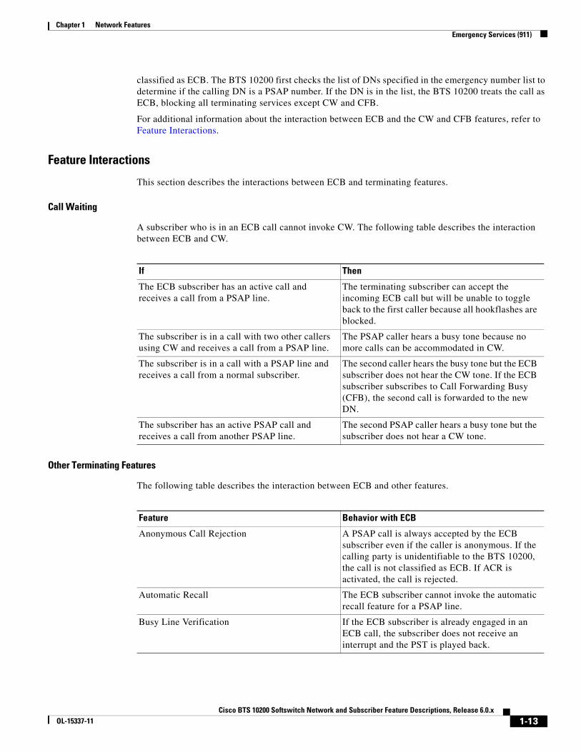
This section describes the interactions between ECB and terminating features.
Call Waiting
A subscriber who is in an ECB call cannot invoke CW. The following table describes the interaction between ECB and CW.
Other Terminating Features
The following table describes the interaction between ECB and other features.
If Then
The ECB subscriber has an active call and receives a call from a PSAP line.
The terminating subscriber can accept the incoming ECB call but will be unable to toggle back to the first caller because all hookflashes are blocked.
The subscriber is in a call with two other callers using CW and receives a call from a PSAP line.
The PSAP caller hears a busy tone because no more calls can be accommodated in CW.
The subscriber is in a call with a PSAP line and receives a call from a normal subscriber.
The second caller hears the busy tone but the ECB subscriber does not hear the CW tone. If the ECB subscriber subscribes to Call Forwarding Busy (CFB), the second call is forwarded to the new DN.
The subscriber has an active PSAP call and receives a call from another PSAP line.
The second PSAP caller hears a busy tone but the subscriber does not hear a CW tone.
Feature Behavior with ECB
Anonymous Call Rejection A PSAP call is always accepted by the ECB subscriber even if the caller is anonymous. If the calling party is unidentifiable to the BTS 10200, the call is not classified as ECB. If ACR is activated, the call is rejected.
Automatic Recall The ECB subscriber cannot invoke the automatic recall feature for a PSAP line.
Busy Line Verification If the ECB subscriber is already engaged in an ECB call, the subscriber does not receive an interrupt and the PST is played back.
1-13Cisco BTS 10200 Softswitch Network and Subscriber Feature Descriptions, Release 6.0.x
OL-15337-11

Chapter 1 Network FeaturesEmergency Services (911)
For information on provisioning this feature, see Cisco BTS 10200 Softswitch Provisioning Guide.
911 Ring Back911 ring back describes a scenario wherein a Public Safety Answering Point (PSAP) operator is communicating with someone who has dialed 911 and the caller hangs up before the PSAP operator has all of the information that the operator needs. The operator commands the terminating switch to ring back the caller.
Note There are two different types of 911 service: Basic 911 (B911) and Enhanced 911 (E911). In B911 it is absolutely necessary that the switch (BTS 10200) retains the call and connection when a caller hangs up. (Because E911 gets location information through ANI, it is unnecessary for the operator to request further information and therefore the local switch can disconnect the call if the caller hangs up.)
CALEA Communications Assistance for Law Enforcement Act (CALEA) is supported for ECB exactly as it is with normal calls.
Call Forwarding Busy If the ECB subscriber is in a call, the PSAP caller hears a busy tone but the call is not forwarded.
Call Forwarding No Answer If the subscriber does not pick up the call, it is not forwarded to the forwarding DN. The CFNA timer is not started and the phone continues to ring.
Call Forwarding Unconditional The subscriber receives the PSAP call even if CFU is activated.
Call Hold/Call Park/Call Transfer/Three Way These services are inhibited during a PSAP call.
Calling Number Delivery/Calling Name Delivery The PSAP calling name and number are not displayed to the subscriber.
Call Waiting Refer to Call Waiting for a description of ECB interaction with CW.
Do Not Disturb The subscriber receives PSAP calls even if DND is activated.
Directed Call Pickup No other subscribers can pick up PSAP calls.
Distinctive Ringing Distinctive ringing is not available.
Multi-Line Hunt Group There is no special handling for MLHG. MLHG behaves the same for ECB and non-ECB calls.
Seasonal Suspend A subscriber who has the seasonal suspend feature enabled can receive calls.
Selective Call Acceptance The PSAP call is not checked against the SCA list, so the call is not blocked.
Selective Call Rejection The PSAP call is not checked against the SCR list, so the call is not blocked.
Temporary Disconnect Temporary disconnect subscribers do not receive ECB calls.
Feature Behavior with ECB
1-14Cisco BTS 10200 Softswitch Network and Subscriber Feature Descriptions, Release 6.0.x
OL-15337-11

Chapter 1 Network FeaturesEmergency Services (911)
When the caller and the PSAP are both on the same BTS 10200, the BTS 10200 retains the call and connection if the B911 caller hangs up. If the caller and the PSAP are on separate BTS 10200 nodes, the connection between the two BTS 10200 nodes is maintained over a SIP trunk.
Sequence of Events for 911 Ring Back
The example shown in Figure 1-1 is a typical sequence of events for the 911 ring back over SIP trunk. In this example, there is a cable subscriber that dials 911 and the call is connected to a PSAP operator. After the connection is established, the cable subscriber hangs up before the operator has gathered all of the necessary information. Upon request from the operator, the BTS 10200 rings back the cable subscriber’s phone so that the conversation with the PSAP operator can continue. Figure 1-1 illustrates the following sequence of events:
1. A subscriber with an emergency situation on BTS2 (BTS2_sub) dials 911.
2. The dial plan is set up to route this call to a SIP trunk. BTS2 sends the SIP INVITE (with the number set to 911) to BTS1.
3. BTS1 receives the SIP INVITE (911) and routes the call to the 911 operator PSAP CAS trunk.
4. The normal SIP trunk call sequence between BTS1 and BTS2 occurs to complete the 911 call.
5. After the connection is established between BTS2_sub and the operator, BTS2_sub hangs up. BTS2 does not release the call because it is a 911 call.
6. When the 911 operator connected to BTS1 detects that BTS2_sub has hung up, the operator applies a hook flash, which generates an MGCP NTFY (operator ring back) from the CAS gateway to BTS1.
7. BTS1 sends a SIP UPDATE with OSPS RING indicator over the SIP trunk towards BTS2.
8. When BTS2 receives the SIP UPDATE with OSPS RING indicator, it sends an MGCP RQNT (ring) to the residential gateway and causes the BTS2_sub phone to ring.
Figure 1-1 Network Diagram for B911 Operator Ring Back
Note The network diagram for E911 is similar to the B911 diagram except that there is always one or more E911 tandem switches between the TG-t and the PSAP.
1913
81
Cisco BTS 10200Softswitch
1
SCP
Routed off-net
Routed on-net
SCP queryif required
Outbound8XX call
3
4Externalnetwork
2
1-15Cisco BTS 10200 Softswitch Network and Subscriber Feature Descriptions, Release 6.0.x
OL-15337-11

Chapter 1 Network FeaturesOperator Services
SIP Trunk Provisioning
The SIP trunk between the two BTS 10200 nodes is provisioned through the softsw-tg-profile table. When you provision the 911 feature, you must provision this table for any SIP trunks between the BTS 10200 nodes. The ENABLE_P_DCS_OSPS_HEADER token in this table has a default value of N; you must set it to Y for this SIP trunk. When this token is set to Y and an OSPS-related request is made, the BTS 10200 includes a P-DCS OSPS header in the outgoing INVITE or UPDATE messages as defined in RFC-3603. If this token is set to N, the system does not send outgoing SIP requests or accept incoming SIP requests that are OSPS related.
Feature Provisioning CommandsTo provision this feature, see the 911 provisioning procedure in the Provisioning Guide.
Operator ServicesThe BTS 10200 supports the operator services specified in Telcordia Requirement FR-271, Operator Services Systems Generic Requirements (OSSGR).
Operator services is a call-processing function that enables callers to access either a live operator or an automated function to complete calls or gain access to information. The service provider can supply this feature or outsource it to a third-party vendor. Some additional functions accomplished by operator services include automatic call distribution, billing detail recording, and information retrieval.
This section includes the following additional topics:
• Numbers Used to Access Operator Services, page 1-16
• Types of Services, page 1-16
• Busy Line Verification (BLV) and Operator Interrupt (OI) Services, page 1-17
Numbers Used to Access Operator ServicesThe following numbers are commonly used to access operator services:
• 0—Local operator support
• 00—Operator support outside the local calling area, by means of a presubscribed interexchange carrier (PIC)
• 0+ area code and number—Operator support when the destination number is known (that is, for collect calls, calling card calls, person-to-person calls, and so forth), using PIC
• CAC+0+—Operator services, using a dialed carrier access code (CAC)
• 01+CC+NN—International operator services, using PIC
• CAC+01+CC+NN—International operator services, using a dialed CAC
Types of ServicesOperator services provided to callers typically include:
1-16Cisco BTS 10200 Softswitch Network and Subscriber Feature Descriptions, Release 6.0.x
OL-15337-11

Chapter 1 Network FeaturesOperator Services
• Assistance
• General information
• Directory assistance
• Dialing instructions
• Rate information
• Credit recording
• Trouble reporting
• Call completion
• Alternate billing services (ABS)
• Calling card calls
• Collect calls
• Third-number calls
• Handling options
• Person-to-person calls
• Conference calls
• Call transfer
• Real-time rating
• Rate quotes
• Time and charges
• Notify
Busy Line Verification (BLV) and Operator Interrupt (OI) ServicesThis section describes busy line verification (BLV) and operator interrupt (OI) services. OI is also referred to as emergency interrupt (EI). BLV and OI services are based on GR-1176 (FSD 80-01-0300), Busy Line Verification, part of Telcordia OSSGR requirements (FR-271).
Description and Operation
BLV service permits the user to obtain operator assistance to determine if a called line is in use. The user dials 0, waits for the operator to pick up the line, and requests BLV service. OI service permits the operator to speak directly with the busy party. The service provider can deny BLV service to any subscriber by setting type=denied for fname=BLV in the subscriber-feature-data table (see the BLV provisioning link listed below). Note that denying BLV also denies OI.
BLV and OI services work as follows:
1. The user calls the operator and requests BLV service regarding a specific called line.
2. The operator provides the BLV service.
3. For OI, the operator interrupts the conversation in progress and relays a message.
4. If the interrupted party at the called line is willing to hang up, he or she does so.
5. The user can originate a new call to the called DN.
1-17Cisco BTS 10200 Softswitch Network and Subscriber Feature Descriptions, Release 6.0.x
OL-15337-11

Chapter 1 Network FeaturesOperator Services
Note At the user’s request, the operator can directly connect the user to the called line.
The BLV feature can be made available to all subscriber lines connected to a BTS 10200 by use of the default office service ID, or to all subscribers in a specific POP using the office service ID. See the “Office Service ID and Default Office Service ID” section on page 3-166 for a general description of this provisionable service.
Feature Interactions
The following feature interactions are applicable to the BLV and OI services:
• When the operator attempts BLV, if the verified party is engaged in a call and has features currently invoked, the operator might receive a busy tone and might not be able to perform an interrupt on the call. In this section, “currently invoked” means that another feature has already been triggered in the call. There are a few exceptions, such as Cancel Call Waiting (CCW) and Do Not Disturb (DND); for example, BLV can be successfully performed even if CCW or DND is currently invoked on the call.
• If the verified party (terminating subscriber) has call forwarding unconditional (CFU) activated, the operator receives a busy tone and cannot perform an interrupt on the call.
BLV/OI over SIP Trunk between BTS 10200 Nodes
When the caller and the operator service position system (OSPS) are on separate BTS 10200 nodes, the connection between the two BTS 10200 nodes is provided by a SIP trunk.
Figure 1-2 shows a typical sequence of events that occur for BLV/OI over the SIP trunk. The sequence deals with the case in which a busy party is involved.
1. A person (the customer) is trying to call a BTS 10200 subscriber (the busy party), but is unable to get through.
2. The customer asks the operator to verify whether or not the busy party is in a phone conversation with another party (the 3rd party).
3. The operator puts the customer on hold and calls the busy party over a BLV (no-test) trunk that is connected to BTS1.
4. BTS1 receives the incoming BLV call and determines that the called party number should be routed out a SIP trunk that is connected to BTS2. It sends a SIP INVITE with BLV indicator to BTS2.
5. BTS2 receives the incoming SIP INVITE with BLV indicator and determines the call should be routed to a cable subscriber (the busy party). When BTS2 determines that the cable subscriber is already connected to the 3rd party, it first creates a connection between the operator and the busy party. Next it conferences this connection with a preexisting connection between the busy part and third party to form a three-way connection between the operator, the busy party, and the 3rd party.
6. The operator now listens to the busy party and 3rd party conversation through special circuitry that garbles their voices to protect their privacy. At this point the operator’s voice is muted by the OSPS.
7. The operator reports back to the customer that the busy party is in a conversation.
8. The customer requests that the operator break into the conversation and ask if the busy party is willing to hang up and take a call from the customers.
1-18Cisco BTS 10200 Softswitch Network and Subscriber Feature Descriptions, Release 6.0.x
OL-15337-11

Chapter 1 Network FeaturesOperator Services
9. The operator puts the customer back on hold and presses an emergency interrupt button on the console which deactivates the garbling circuitry, un-mutes the microphone, and sends an emergency (operator) interrupt tone over the line, so that the busy party and the 3rd party know that the operator is interrupting into their conversation.
10. The Trunking Gateway recognizes the operator interrupt tone and sends a NTFY event to BTS1. BTS1 translates NTFY event into an outgoing SIP UPDATE (operator interrupt) message that is sent towards BTS2. BTS2 responds to the UPDATE with a 200OK (but does not act on it).
11. The operator explains to the busy party that another caller (the customer) would like to speak with the busy party and asks if the busy party is willing to hang up and accept the call. The operator then releases the connection to them and reports back to the customer that is on hold.
12. If the busy party agrees to hang up, the customer has the option of redialing the number or completing the call as an operator-assisted call.
In Figure 1-2, the customer and 3rd party are shown to be in the PSTN (SS7) network, but they could be elsewhere.
Figure 1-2 Network Diagram for BLV/OI
The SIP trunk between the two BTS 10200 nodes is provisioned through the softsw-tg-profile table. When you provision the BLV feature, you must provision this table for any SIP trunks between the BTS 10200 nodes. The ENABLE_P_DCS_OSPS_HEADER token in this table has a default value of N;
1911
69
BTS 102001
Cable Modem/MTA
TG-t
OSPSOSPS
operator
ITP
BLV CAS trunk
MGCP NCS
SIP
BTS 102002
MGCP Sigtran
PSTNswitch
TG-t
RTP
Customer
Thirdparty
RTP
Announcementserver
RTPCMTS/trunkinggateway
Busyparty
SS7
TDM
OSPS overSIP components
RTP
1-19Cisco BTS 10200 Softswitch Network and Subscriber Feature Descriptions, Release 6.0.x
OL-15337-11

Chapter 1 Network FeaturesSIP Triggers
you must set it to Y for this SIP trunk. When this token is set to Y and an OSPS-related request is made, the BTS 10200 includes a P-DCS OSPS header in the outgoing INVITE or UPDATE messages as defined in RFC-3603. If this token is set to N, the system does not send outgoing SIP requests or accept incoming SIP requests that are OSPS related.
Feature Provisioning Commands
To provision this feature, see the BLV provisioning procedure in the Provisioning Guide.
SIP TriggersThis section describes the SIP triggers feature. Also refer to the “BTS 10200 CALEA Interaction with SIP Triggers Feature” section on page 2-9.
Feature LimitationSIP triggers are not supported for Centrex subscribers.
Technical Description of SIP TriggersThe SIP Triggers feature uses the SIP protocol, with some extensions, to enable the BTS 10200 to interoperate with third-party application servers so that Multi-Service Operators (MSOs) can provide customers with enhanced features and services. The triggers can be used by the third-party servers to provide originating services (such as voice dial) when a subscriber places a call, and enhanced terminating services (such as TV caller ID and custom ringback) when a subscriber receives a call. This section describes the triggers that enable this interoperation with the third-party application servers.
The BTS 10200 supports multiple application servers. Application servers are provisioned per subscriber origination and subscriber termination. You can provision SIP triggers on an individual subscriber level on the BTS 10200.
From the perspective of the BTS 10200, a SIP subscriber appears as a SIP user agent (UA); this is true whether the subscriber’s device is a SIP eMTA, ATA, or PAP2. At the customer premises, the subscriber’s device performs the role of the UA, and might perform other operational functions as well.
Figure 1-3 shows a typical network architecture for SIP triggers, including the connection between the BTS 10200 and the third-party application server.
1-20Cisco BTS 10200 Softswitch Network and Subscriber Feature Descriptions, Release 6.0.x
OL-15337-11

Chapter 1 Network FeaturesSIP Triggers
Figure 1-3 Typical Network Architecture for SIP Triggers
Acronyms for Figure 1-3
CALEA—Communications Assistance for Law Enforcement Act
NCS—Network-based call signaling
SBC—Session border controller
CMTS—Cable modem termination system
IVR—Interactive voice response
Terminology Used in this SectionThe following terminology is used in this section:
• TAT_1 and TAT_2—Termination attempt triggers, collectively referred to as TAT in this document. These triggers occur at different points in the call; TAT_1 occurs before TAT_2, and can be used by an external application server to provide specific services at specific points in the call. These triggers are provisioned as fname=TAT_1 and fname=TAT_2.
• OHD—Off-hook trigger with provisionable delay. The OHD trigger for each subscriber can be designated as off-hook immediate (OHI) or off-hook delayed (OHD). For MGCP and NCS subscribers. you provision the specific trigger type through the offhook-trigger-type parameter in the Subscriber table:
– OHD occurs when a provisionable timer (ohd-timer) runs out after the caller goes off-hook.
– OHI occurs immediately after the caller goes off-hook.
250111
SBC
Third-party networkelements
IP
BTS 10200
SIP Phone
CALEAdelivery function
CMTSMTA
Catalystswitch
Announcementserver
Voice-mailserver
Applicationserver
Call content
NCS
SIP
MGCP
SIP
IVR
Call content Call data
SIP
1-21Cisco BTS 10200 Softswitch Network and Subscriber Feature Descriptions, Release 6.0.x
OL-15337-11

Chapter 1 Network FeaturesSIP Triggers
Off-Hook Trigger (Delayed and Immediate)The BTS 10200 responds to the OHD trigger differently for MGCP/NCS subscribers than for SIP subscribers.
There is an OHD trigger provisioned as fname=OHD in the Feature table, and there is a delayed or immediate designation provisioned as offhook-trigger-type=OHD or OHI in the Subscriber table. The ohd_timer parameter is also provisioned in the Subscriber table.
Note The BTS 10200 does not invoke the ohd-timer for SIP subscribers.
OHD Treatment for MGCP/NCS Subscribers
The OHD trigger occurs either immediately after the user goes off-hook (if offhook-trigger-type in the Subscriber table is set to OHI) or after a delay set through a configurable timer (if offhook-trigger-type=OHD).
• If off-hook immediate is provisioned, the BTS_10200 establishes a connection to the external application server provisioned for that combination of subscriber and trigger, and sends the call to the server immediately after the caller goes off-hook.
• If off-hook delayed is provisioned and the user goes off-hook, dial tone is provided to the subscriber for the configured number of seconds. When the delay timer expires, dial tone is stopped and the BTS 10200 establishes a connection to the external application server provisioned for that combination of subscriber and trigger, and sends the call to the server. If the user starts dialing before the delay timer expires, the BTS 10200 allows digit collection to be completed before establishing the connection to the application server. Depending on the service invoked (for example, dial by name), the application server determines the desired called party and sends the call back to the BTS 10200 to continue originating processing.
OHD Treatment for SIP Subscribers
When the BTS 10200 receives an INVITE message from the SIP subscriber (that is, from the UA), it takes actions based on the content of the incoming INVITE and the parameters provisioned in the BTS 10200 database.
This section contains the following topics:
• OHD Associated with a Vertical Service Code, page 1-22
• OHD Assigned to the Subscriber, page 1-23
• OHD Call Flow Diagrams, page 1-23
OHD Associated with a Vertical Service Code
You can associate the OHD feature with a specific vertical service code (VSC), for example fname=OHD and digit_string=*40. In this case, if the BTS 10200 receives ad INVITE from the UA, it takes the following action:
• If the incoming INVITE To header begins with *40, the BTS 10200 strips off all digits and sends the INVITE to the application server. Here are examples of this process:
INVITE(*40) ->BTS 10200-> INVITE( )INVITE(*40 + 10DIGITS) ->BTS 10200-> INVITE( )
1-22Cisco BTS 10200 Softswitch Network and Subscriber Feature Descriptions, Release 6.0.x
OL-15337-11

Chapter 1 Network FeaturesSIP Triggers
• If the incoming INVITE To header does not begin with the provisioned VSC digit string for the OHD feature (*40 in this example), the BTS 10200 processes the call locally without sending it to the application server.
OHD Assigned to the Subscriber
You can assign the OHD feature to a subscriber, and designate the value of the offhook_trigger_type (in the Subscriber table) as OHD or OHI. In this case, when the BTS 10200 receives an INVITE from the UA, it takes the following action:
• If offhook_trigger_type is set to OHI, the BTS 10200 sends an INVITE (without any VSC or digits) to the application server. Here are examples of this process:
INVITE(*92 + 10DIGITS) ->BTS 10200-> INVITE( )INVITE(*40 + 10DIGITS) ->BTS 10200-> INVITE( )
• If offhook_trigger_type is set to OHD, and the incoming INVITE To header begins with any VSC, the BTS 10200 sends the INVITE (including the original VSC and any digits received) to the application server. Here are examples of this process:
INVITE(*92 + 10DIGITS) ->BTS 10200-> INVITE(*92 + 10DIGITS)INVITE(*40 + 10DIGITS) ->BTS 10200-> INVITE(*40 + 10DIGITS)
• If offhook_trigger_type is set to OHD, and the incoming INVITE To header contains dialed digits (but no VSC), the BTS 10200 proceeds as follows:
– If the dialed digits match a DN that is provisioned in the BTS 10200 with call_type=EMG (an emergency call such as 911), the BTS 10200 checks the value provisioned for EMG-ROUTE-TO-AS in the ca_config table. If it is set to N (default), the BTS 10200 processes the emergency call locally without sending it to the application server.
– If the dialed digits are for an EMG call and EMG-ROUTE-TO-AS is set to Y, the BTS 10200 sends the INVITE (including the dialed digits) to the application server. Here are examples of this process:
INVITE(911) ->BTS 10200-> INVITE(911)INVITE(110) ->BTS 10200-> INVITE(110)
– If the dialed digits are for a regular (nonemergency) DN, the BTS 10200 checks the value provisioned for ROUTE-CALLS-TO-AS-WITH-DIGITS in the ca_config table. If it is set to N, the BTS 10200 processes the call locally without sending it to the application server.
– If the dialed digits are for a regular (nonemergency) DN and ROUTE-CALLS-TO-AS-WITH-DIGITS is set to Y (default), the BTS 10200 sends the INVITE (including the dialed digits) to the application server. Here is an example of this process:
INVITE(3925550123) ->BTS 10200-> INVITE(3925550123)
When the SIP trigger is not sent successfully to the application server due to a sever or network connectivity problem due to any problem, the BTS 10200 connects the call to an IVR server to enable digit collection and call completion. However, if the IVR connection is unsuccessful, the call fails.
OHD Call Flow Diagrams
The diagrams in this section show examples of OHD call flows for SIP subscribers
The OHI scenario is shown in Figure 1-4.
1-23Cisco BTS 10200 Softswitch Network and Subscriber Feature Descriptions, Release 6.0.x
OL-15337-11

Chapter 1 Network FeaturesSIP Triggers
Figure 1-4 Offhook_trigger_type set to OHI
The OHD scenario is shown in Figure 1-5.
Figure 1-5 Offhook_trigger_type set to OHD
SUBoffhook
INVITE (AS VSC)sent by SIP UA
to BTS
INVITE ()Sent from BTS
to AS
2809
27
SUBoffhook
INVITE (AS VSC)sent by SIP UA
to BTS
INVITE ()Sent from BTS
to AS
2809
28
SUB dialsbefore UA timer
expires?
Did userdial AS VSC
ROUTECALLS-TO-AS-
WITH-DIGITS=
INVITE (user dialeddigits) sent bySIP UA to BTS
No
Yes
No
Yes
Yes
Yes
Call Type=EMG
EMG-ROUTE-TO-AS=
INVITE (EMG DN)Sent from BTS
to AS
INVITE ()Sent from BTS to AS
(AS VSC is stripped off)
Process Call locally(no AS involvement)
Yes
No
INVITE (user dialed digits)
Sent from BTS to ASNo
Process EMG Calllocally (no ASinvolvement)
No
1-24Cisco BTS 10200 Softswitch Network and Subscriber Feature Descriptions, Release 6.0.x
OL-15337-11

Chapter 1 Network FeaturesSIP Triggers
The usage-sensitive scenario is shown in Figure 1-6.
Figure 1-6 Usage-Sensitive OHD Scenario
Route Headers for OHD
The BTS 10200 inserts two route headers in the INVITE that is sent to the application server:
• Topmost route header—Intended for the application server to identify the logic to be executed on the application server and can be either provisioned at the BTS 10200 per subscriber, or set with a default for all Off-Hook Delay subscribers.
• Return route header—Intended to identify the necessary call session and processing information when the INVITE is returned to the BTS 10200. This route header must be returned unchanged to the BTS 10200 in the INVITE that is sent from the application server to the BTS 10200.
SUBoffhook
2809
29
Did userdial AS VSC
Are theremore digits
following theAS VSC?
INVITE (user dialeddigits) sent bySIP UA to BTS
Yes
Yes
Yes
Yes
Call Type=EMG
EMG-ROUTE-TO-AS=
INVITE (EMG DN)Sent from BTS
to AS
INVITE ()Sent from BTS to AS
(AS VSC is stripped off)
Process Call locally(no AS involvement)
No
INVITE (user dialed digits)
Sent from BTS to AS(AS VSC is stripped off)
No
No
Process EMG Calllocally (no ASinvolvement)
No
1-25Cisco BTS 10200 Softswitch Network and Subscriber Feature Descriptions, Release 6.0.x
OL-15337-11

Chapter 1 Network FeaturesSIP Triggers
Termination Attempt Triggers (TAT_1 and TAT_2)This trigger occurs when a call terminates to a BTS 10200 subscriber that has one or both TAT triggers (TAT_1 and TAT_2) enabled. The BTS 10200 sends the terminating call to the external application server before ringing the subscriber. The application server may provide services such as screening or custom ringback. If the application server determines that the call should be offered to the subscriber, it sends the call back to the BTS 10200 to continue termination processing.
The TAT triggers operate as follows:
• The TAT_1 trigger takes precedence over all other BTS 10200 terminating features at the TERMINATION_ATTEMPT_AUTHORIZED trigger detection point. However, if the CNAM TCAP query is provisioned for a subscriber, it is performed before the TAT_1 trigger and the name is provided to the application server. The BTS 10200 honors the calling name it receives from the application server and does not launch a CNAM query again if the name is present in the INVITE received back from the application server.
• The TAT_2 trigger is the last feature invoked at the TERMINATION_ATTEMPT_AUTHORIZED trigger detection point.
A TAT trigger is not disabled even if the user is in an Emergency call. However, a return INVITE from the application server fails at the BTS 10200 if the user is in an Emergency call.
As it processes a TAT, the BTS 10200 manages the following scenarios:
• Successful application server invocation
• Unsuccessful application server invocation
• Application server terminates call
• Application server sends call back to the BTS 10200 for termination processing
The system populates two Route headers in the INVITE it sends to the application server. The contents of the Route headers are controlled by provisioning. The provisioning of the first Route header is determined by the requirements of the application server and that of the second is determined by the requirements of the BTS 10200. The following examples illustrate the format of the Route field, with both the first Route header and return Route header shown in the example:
Examples—Route header in the INVITE Message:Route: <topmost route>,<return route>;service-ref=SCM0579081256
Route: <sip:TAT_1-app@APP_SERVER1.serviceprovider.com;lr>, <sip:[email protected];lr>;service-ref=SCM0579081256
Route: <sip:TAT_2-app@APP_SERVER1.serviceprovider.com;lr>, <sip:[email protected];lr>;service-ref=SCM0537491333
Note The meaning of lr in the route header is loose routing. See RFC 3261 for a description.
Subscriber FeaturesThe following are examples of services that could be offered in conjunction with the TAT and OHD triggers if there ia an appropriate application server in the network.
• Voice Menu (Off-Hook Delay Trigger)
1-26Cisco BTS 10200 Softswitch Network and Subscriber Feature Descriptions, Release 6.0.x
OL-15337-11

Chapter 1 Network FeaturesSIP Triggers
• Voice Dialing (Off-Hook Delay Trigger)
• Multi-party Voice Dialing (Off-Hook Delay Trigger)
• TV-Caller ID: with or without Picture (Terminating Trigger)
• Custom Ring-back Tone (Terminating Trigger)
• Enhanced Voicemail UI (Off-Hook Delay Trigger)
• Message Status (Off-Hook Delay Trigger)
• Missed Call Status (Off-Hook Delay Trigger)
• Voicemail Screening (Specific Digit String (vertical service code))
• Smart Call Forward (Terminating Trigger)
• Smart Call Return (Off-Hook Delay Trigger)
• Dialpad Sound Effects (Off-Hook Delay Trigger)
• Multi-Ring Call Forward (Terminating Trigger)
• Click to Dial (3PCC mechanisms)
Note Support of subscriber features is not limited to those identified in the preceding list.
Failover BehaviorDuring transitions (for example, while the call to the application server is being placed or while the call from the application server is placed to the destination), a failover of the call agent or feature server is likely to cause the call to be dropped.
If a call is connected to the application server, or if a call is connected end to end, a failover of the call agent or feature server does not disrupt the call.
Feature Interactions for OHD TriggerThe OHD trigger is supported for MGCP, NCS, and SIP subscribers. Features that are provided by the application server interwork with the features provided by the BTS 10200. Table 1-3 describes the feature interactions for the OHD trigger.
1-27Cisco BTS 10200 Softswitch Network and Subscriber Feature Descriptions, Release 6.0.x
OL-15337-11

Chapter 1 Network FeaturesSIP Triggers
Table 1-3 Feature Interactions for OHD Trigger
Feature Abbreviation Feature Interaction
Vertical Service Codes (VSCs):
• Activation, deactivation, and interrogation features, including the use of VSCs, for example AC_ACT, AC_DEACT, CBLK, CCW, CFUA, CFBI, CNAB, CNDB, COT, DND_ACT, and DND_DEACT.
• VSCs dialed to access feature management functions, for example PS_MANAGE, PS_O, CIDSD, CIDSS, VM_ACCESS.
• Initial VSCs entered by the handset user to invoke AC and AR.
(various) If the user dials the VSC during the dial tone, the BTS 10200 collects the VSC digits and then forwards the call to the application server. If the user dials the VSC after the BTS 10200 establishes the call to the application server, the application server collects the VSC digits.
The application server is configured to send the REFER back to the BTS 10200 with the VSC if it is not capable of handling this VSC. When the REFER is received by the BTS 10200, the BTS 10200 provides origination processing. During origination processing, if more digits must be collected, the BTS 10200 does so by playing appropriate tones directly at the endpoint.
After the process (activation, deactivation, interrogation, or feature management) is complete, the BTS 10200 does not invoke SIP triggers to the application server again.
Toll Free 8xx OHD Trigger takes precedence.
Emergency Service 911 Emergency calls are routed to the application server if the BTS 10200 Call Agent Configuration table is provisioned to do so:
add ca-config type=EMG-ROUTE-TO-AS;datatype=BOOLEAN; VALUE=Y;
If EMG-ROUTE-TO-AS is set to N (default), the BTS 10200 processes the call locally and does not invoke the application server.
If EMG-ROUTE-TO-AS is set to Y and the dialed digits match the digit string provisioned in the emergency-number-list table, the BTS 10200 has the capability to route the call to the application server. The actual treatment of the call is as follows:
• If the user dials the emergency number before the call is connected to the application server, the BTS 10200 processes the call locally and does not invoke the application server.
• If the user dials the emergency number after the call is connected to the application server, the application server is expected to collect the digits and send a REFER or return INVITE to the BTS 10200. When the BTS 10200 receives the REFER or return INVITE, it makes the call to the emergency number.
Automatic Callback AC When the subscriber enters the VSC on the handset, the BTS 10200 invokes the OHD trigger.
When the BTS 10200 calls back the subscriber, the callback does not invoke OHD.
When the BTS 10200 sets up the final call to the remote phone, it treats this as a new call and invokes the OHD trigger to the application server.
1-28Cisco BTS 10200 Softswitch Network and Subscriber Feature Descriptions, Release 6.0.x
OL-15337-11

Chapter 1 Network FeaturesSIP Triggers
Automatic Recall AR Same as AC.
Class of Service COS OHD takes precedence and COS screening is applied after the return INVITE from the application server is received at the BTS 10200.
Authorization Code and Account Code features are already being supported using IVR. Therefore, these features, if needed, can be configured on the BTS 10200 to be supported using IVR.
Call Transfer CT A second origination attempt also goes through the application server.
Hotline HOTLINE If HOTLINE and OHD are active, the hotline number is expanded and the number is included in the request URI user part sent to the application server.
Hotline Variable HOTV Same as Hotline.
Limited Call Duration LCD OHD takes precedence and the process of checking the prepaid server occurs after the return INVITE is received from the feature server.
Local Number Portability LNP OHD takes precedence and a local number portability query is invoked after the return INVITE is received from the feature server.
Outgoing Call Barring OCB OHD takes precedence and OCB is applied after the application server sends the call back to the BTS 10200.
Speed Call - 1 /2 digit SC1D
SC2D
Call is routed to the application server with the speed-dial digits. When the return INVITE is received from the application server, the BTS 10200 provides the speed call functionality.
Three Way Call TWC The second origination attempt goes to the application server.
Three Way Call Deluxe TWCD Same as TWC.
Usage Sensitive Three Way Call USTWC Same as TWC.
Warmline WARMLINE If warm line and OHD are provisioned, the warmline number is included in the INVITE message (user part of request URI) to the application server.
Note If a subscriber is provisioned for both warmline and OHD, the delay for OHD should not be used. Either the subscriber dials before the warmline timeout and the dialed number is provided to the application server, or the warmline timeout occurs, and the warmline number is provided to the application server. The application server will not collect digits. Off Hook Immediate is not available. Speak to Dial is not available.
Similarly, the offhook delay timer for OHD is not used if hotline is also active. If both OHD and hotline are active, the BTS 10200 will immediately send an INVITE to the application server that includes the provisioned hotline number. The user will not receive an initial dial tone.
Table 1-3 Feature Interactions for OHD Trigger (continued)
Feature Abbreviation Feature Interaction
1-29Cisco BTS 10200 Softswitch Network and Subscriber Feature Descriptions, Release 6.0.x
OL-15337-11
Chapter 1 Network FeaturesSIP Triggers
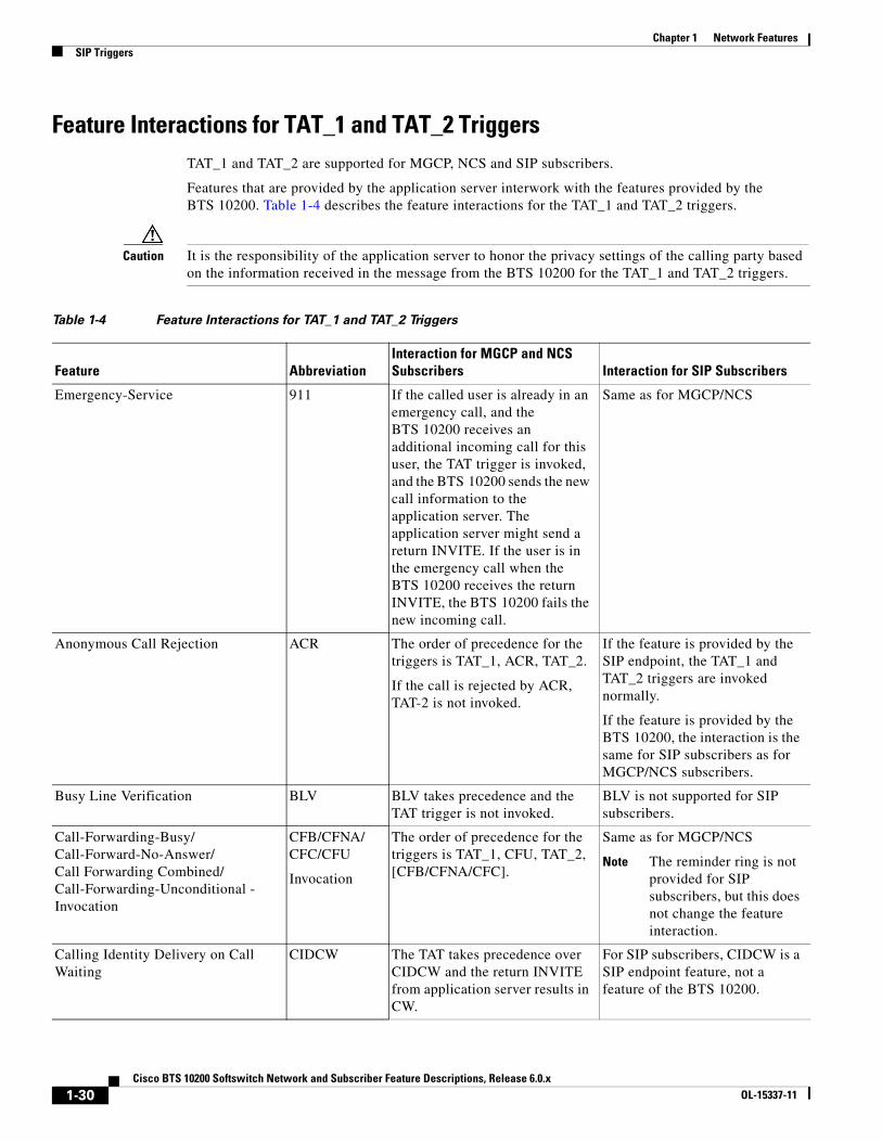
Feature Interactions for TAT_1 and TAT_2 TriggersTAT_1 and TAT_2 are supported for MGCP, NCS and SIP subscribers.
Features that are provided by the application server interwork with the features provided by the BTS 10200. Table 1-4 describes the feature interactions for the TAT_1 and TAT_2 triggers.
Caution It is the responsibility of the application server to honor the privacy settings of the calling party based on the information received in the message from the BTS 10200 for the TAT_1 and TAT_2 triggers.
Table 1-4 Feature Interactions for TAT_1 and TAT_2 Triggers
Feature Abbreviation Interaction for MGCP and NCS Subscribers Interaction for SIP Subscribers
Emergency-Service 911 If the called user is already in an emergency call, and the BTS 10200 receives an additional incoming call for this user, the TAT trigger is invoked, and the BTS 10200 sends the new call information to the application server. The application server might send a return INVITE. If the user is in the emergency call when the BTS 10200 receives the return INVITE, the BTS 10200 fails the new incoming call.
Same as for MGCP/NCS
Anonymous Call Rejection ACR The order of precedence for the triggers is TAT_1, ACR, TAT_2.
If the call is rejected by ACR, TAT-2 is not invoked.
If the feature is provided by the SIP endpoint, the TAT_1 and TAT_2 triggers are invoked normally.
If the feature is provided by the BTS 10200, the interaction is the same for SIP subscribers as for MGCP/NCS subscribers.
Busy Line Verification BLV BLV takes precedence and the TAT trigger is not invoked.
BLV is not supported for SIP subscribers.
Call-Forwarding-Busy/Call-Forward-No-Answer/Call Forwarding Combined/Call-Forwarding-Unconditional - Invocation
CFB/CFNA/CFC/CFU
Invocation
The order of precedence for the triggers is TAT_1, CFU, TAT_2, [CFB/CFNA/CFC].
Same as for MGCP/NCS
Note The reminder ring is not provided for SIP subscribers, but this does not change the feature interaction.
Calling Identity Delivery on Call Waiting
CIDCW The TAT takes precedence over CIDCW and the return INVITE from application server results in CW.
For SIP subscribers, CIDCW is a SIP endpoint feature, not a feature of the BTS 10200.
1-30Cisco BTS 10200 Softswitch Network and Subscriber Feature Descriptions, Release 6.0.x
OL-15337-11

Chapter 1 Network FeaturesSIP Triggers
Provisioning CommandsTo provision this feature, see the “SIP Triggers” provisioning procedure in the Provisioning Guide.
Calling Name Delivery CNAM The CNAM query is performed before the TAT is invoked.
Same as for MGCP/NCS
Calling Number Delivery CND The application server is a trusted entity; therefore, the calling number is always delivered to the application server.
Same as for MGCP/NCS
Call Waiting CW The TAT takes precedence over CW and the return INVITE from application server results in CW.
For SIP subscribers, CW is a SIP endpoint feature, not a feature of the BTS 10200.
Call Waiting Deluxe CWD Same as CW. Same as CW.
Do Not Disturb DND TAT-1 takes precedence and DND is invoked after receiving the return INVITE from the application server.
Note DND takes precedence over TAT-2.
If the feature is provided by the SIP endpoint, the TAT_1 and TAT_2 triggers are invoked normally.
If the feature is provided by the BTS 10200, the interaction is the same for SIP subscribers as for MGCP/NCS subscribers.
Distinctive Ringing Call Waiting DRCW The order of precedence for the triggers is TAT_1, TAT_2, DRCW.
Same as for MGCP/NCS
No Solicitation Announcement NSA The order of precedence for the triggers is TAT_1, NSA, TAT_2.
Same as for MGCP/NCS
Privacy Screening PS The order of precedence for the triggers is TAT_1, PS, TAT_2.
Same as for MGCP/NCS
Remote Call Forwarding RCF The TAT-1 trigger takes precedence over RCF.
Same as for MGCP/NCS
Selective Call Acceptance/Selective Call Forwarding/Selective Call Rejection
SCA/SCF/SCR TAT-1 takes precedence and SCA/SCF/SCR is invoked after receiving the return INVITE from the application server. SCA/SCF/SCR takes precedence over TAT-2.
Same as for MGCP/NCS
Voicemail VM The order of precedence for the triggers is TAT_1, VM, TAT_2.
Same as for MGCP/NCS
Voicemail Always VMA The TAT-1 trigger takes precedence over VMA.
Same as for MGCP/NCS
Table 1-4 Feature Interactions for TAT_1 and TAT_2 Triggers (continued)
Feature Abbreviation Interaction for MGCP and NCS Subscribers Interaction for SIP Subscribers
1-31Cisco BTS 10200 Softswitch Network and Subscriber Feature Descriptions, Release 6.0.x
OL-15337-11

Chapter 1 Network FeaturesSIP Triggers
Error HandlingThis section describes how the BTS 10200 operates when it receives 4xx, 5xx, and 6xx responses over the IP Multimedia Subsystem (IMS) Service Control (ISC) interface from the application server.
Table 1-5 lists the response codes and indicates how the BTS 10200 operates when it receives 4xx, 5xx, and 6xx responses over the ISC/application server interface.
Table 1-5 uses the following terms:
• Continue—Indicates that the BTS 10200 processes the call locally. In the case of the OHI or OHD trigger with no digits, the BTS 10200 prompts the user, collects the address digits, and then processes the call locally.
• Error Treatment—Indicates that the BTS 10200 connects the user to a configured tone or announcement and then disconnects the call.
Table 1-5 BTS 10200 Management of Error Response Codes
Response Code OHI or OHD with No Digits OHD with Digits, TAT
400—Bad Request Continue Continue
401—Unauthorized Continue Continue
402—Payment Required Continue Continue
403—Forbidden Continue Error Treatment
404—Not Found1 Continue Continue
405—Method Not Allowed Continue Continue
406—Not Acceptable Continue Continue
407—Proxy Authentication Required Continue Continue
408—Request Timeout Continue Continue
410—Gone Continue Error Treatment
413—Request Entity Too Large Continue Continue
414—Request URI Too Large Continue Continue
415—Unsupported Media Type Continue Continue
416—Unsupported URI Scheme Continue Continue
420—Bad Extension Continue Continue
421—Extension Required Continue Continue
423—Interval Too Brief Continue Continue
480—Temporarily Unavailable Continue Continue
481—Call/Transaction Does Not Exist Continue Continue
482—Loop Detected Continue Error Treatment
483—Too Many Hops Continue Continue
484—Address Incomplete Continue Error Treatment
485—Ambiguous Continue Continue
486—Busy Here Continue Error Treatment
487—Request Terminated Continue Error Treatment
1-32Cisco BTS 10200 Softswitch Network and Subscriber Feature Descriptions, Release 6.0.x
OL-15337-11

Chapter 1 Network Features8XX (Toll-Free Calling)
8XX (Toll-Free Calling)The toll-free feature enables the called party, rather than the calling party, to be charged for a call. These calls are prefixed with the 1+8XX service access codes. The seven digits following the 8XX codes are used for routing the call. For an inbound or outbound 8XX call, the BTS 10200 checks the local toll-free database first. If the corresponding DN is not found in the local toll-free database, the system sends a query to the service control point (SCP) to request the corresponding DN.
All aspects of toll-free calling are transparent to the caller. A caller expects to dial 1-8XX-NXX-XXXX to reach the desired destination. The company that translates the number to a specific DN and the company that routes the call must appear transparent to callers. Most callers are not aware that their dialed 8XX number is changed into a specific DN. What matters to the callers is that they reach what they perceive to be the called number, and they are not billed for the call.
Note The toll-free (8XX) feature can be made available to all subscriber lines connected to a BTS 10200 using the default office service ID, or to all subscribers in a specific POP using the office service ID. See the “Office Service ID and Default Office Service ID” section on page 3-166 for a general description of this provisionable service.
Reference: SR-2275, Sec. 14.6.
488—Not Acceptable Here Continue Continue
491—Request Pending Continue Continue
493—Undecipherable Continue Continue
500—Server Internal Error Continue Continue
501—Not Implemented Continue Continue
502—Bad Gateway Continue Error Treatment
503—Service Unavailable Continue Continue
504—Server Timeout Continue Continue
505—Version Not Supported Continue Continue
513—Message Too Large Continue Continue
600—Busy Everywhere Continue Error Treatment
603—Decline Continue Error Treatment
604—Does Not Exist Anywhere Continue Error Treatment
606—Not Acceptable Continue Error Treatment
1. The application server might send a 404 or 305 response code if the user is not subscribed to the requested service (feature). If a 305 is returned, the FQDN of the contact header received in the 305 must be of the receiving BTS 10200. Receiving the 305 prompts the BTS 10200 to continue to process the call locally without reengaging the application server. If the BTS 10200 receives a 404 response code, it continues to process the call locally. The 404 also might be generated by a downstream node; but, the BTS 10200 is not able to differentiate if the 404 is generated by the application server or the downstream node. Therefore, attempting to process the call locally might fail again. The number of times that the BTS 10200 reattempts this “failed call” can depend on the number of triggers executed before the 404 error is encountered. In the worse case, if a user is configured with OHD, TAT_1, and TAT_2, the BTS 10200 can reattempt the call four times before the caller is connected to error treatment.
Table 1-5 BTS 10200 Management of Error Response Codes (continued)
Response Code OHI or OHD with No Digits OHD with Digits, TAT
1-33Cisco BTS 10200 Softswitch Network and Subscriber Feature Descriptions, Release 6.0.x
OL-15337-11

Chapter 1 Network Features8XX (Toll-Free Calling)
8XX Call ProcessingThe system processes outbound 8XX calls as follows:
1. The CA signals the AIN FS to perform an 8XX query.
2. The AIN FS performs an internal database query.
3. If an internal record is found for the 8XX number, the AIN FS provides the routing information to the CA and the call is attempted.
Note For an incoming 8XX call that has a network-specific NOA (based on GR-317), when the system finds the record in the internal database, it assigns the value 2 (TOLL_FREE_LOCAL) to the Database Query Type1 field in the resulting call detail record (CDR).
4. If no internal record is found, the next action depends on how the NOA token is provisioned in the dial plan table. If NOA is provisioned as NATIONAL (the default value), the AIN FS performs an external service control point (SCP) query. If a route is found, the CA completes the call. Otherwise the call is released.
Note For an incoming 8XX call that has a network-specific NOA, the system does not attempt an external query. The call is released with release cause No Route to Destination.
Figure 1-7 shows the processing of an outbound 8XX call placed by a subscriber.
Figure 1-7 Processing of an Outbound 8XX Call
Notes for Figure 1-7
1. A subscriber dials an 8XX call.
2. The system attempts to translate the 8XX call to a DN in its local database.
3. If there is no record in the local database, the system sends a query to the SCP and receives a translated DN.
4. The system routes the call to the appropriate subscriber (on-net call) or external network (off-net call).
Figure 1-8 shows the processing of an 8XX call received from the network with a network-specific NOA.
1913
81
Cisco BTS 10200Softswitch
1
SCP
Routed off-net
Routed on-net
SCP queryif required
Outbound8XX call
3
4Externalnetwork
2
1-34Cisco BTS 10200 Softswitch Network and Subscriber Feature Descriptions, Release 6.0.x
OL-15337-11

Chapter 1 Network Features8XX (Toll-Free Calling)
Figure 1-8 Processing of an 8XX Call with a Network-Specific NOA
Notes for Figure 1-8
1. The system receives an incoming SS7 call with a toll-free (8XX) dialed DN and with NOA=network-specific.
2. The system attempts to translate the 8XX call to a DN in its local database.
3. The system routes the call to the appropriate subscriber (on-net call) or external network (off-net call).
Local Toll-Free DatabaseThis section explains how the system uses information from the local toll-free database.
The BTS 10200 translates inbound and outbound 8XX numbers at the Feature Server (FS) using a local 8XX database. The 8XX service supports the following features:
• Origin-dependent routing
• Time-of-day routing
• Percentage-based routing
• Information digit-based screening
• Black/white list screening
The BTS 10200 also supports optional DNIS service. In an 8XX DNIS service, when a call is terminated to a PBX (call center), 4 digits are outpulsed to the PBX to identify the originally dialed 8XX number. In case of custom DNIS, up to 22 digits can be outpulsed with additional information such as:
• Original 8XX number dialed
• Automatic number identification (ANI)
• Originating line information of the calling party
When a translated number (for an original 8XX call) is received, the Analyzed Info DP triggers the FS. The BTS 10200 looks up the DNIS and TG information for the call. The DNIS information is then outpulsed to the PBX. If an overflow condition is encountered, the call is routed to the overflow trunk. The overflow trunk can be a PSTN trunk.
See SR-2275, Telcordia Notes on the Network, Section 14.6, for additional information on toll-free database services.
1913
82
Cisco BTS 10200Softswitch
1
Routed off-net
Routed on-net3
Externalnetwork
2
Incoming SS7 call (dialed as 8XX)and NOA = network-specific
1-35Cisco BTS 10200 Softswitch Network and Subscriber Feature Descriptions, Release 6.0.x
OL-15337-11
Chapter 1 Network FeaturesActive Call Information Display
SCP-Based Toll-Free ServicesThis section explains how the system uses information from the external toll-free database.
The BTS 10200 communicates with an SCP-based database called the toll-free database service, which contains information for routing the call. The database service provides information about the network service provider selected to complete the call and information for translating the toll-free number to a specific 10-digit directory number (DN). The routing of the call can vary depending on the arrangements made between the toll-free subscriber and the network service provider. These arrangements can include selective routing based on the time of day, day of week, and location from which the call originates.
Direct Calls to C-numbersCertain directory numbers such as 7XX, 8XX, or 9XX numbers, when dialed get translated into a specific DN. These specific DNs, also known as C-numbers, cannot be directly dialed by a subscriber and can be reached by using 7XX, 8XX, or 9XX numbers.
C-numbers are set as dialable in the OFFICE-CODE table. See the Cisco BTS 10200 Softswitch CLI Database for information on this table. When the DIALABLE token is set as N, the number cannot be reached through user dialing.
The CALL-OFFERING-ALLOWED token in the CPC table enables the service provider to override the value set for DIALABLE token in the OFFICE-CODE table.
When a call is received and its calling party category is provisioned in the CPC table, BTS 10200 overrides DIALABLE=N set for the called office code number when CALL-OFFERING-ALLOWED is Y in the CPC table. This setting allows the call to directly terminate to the translated number.
To support this feature, "translated number" with value 246 is added for "Calling Party Category" CDB field in the billing record.
See the Cisco BTS 10200 Softswitch CLI Database for information on using the CPC table.
Provisioning CommandsTo provision this feature, see the 8XX (Toll-Free Calling) provisioning procedure in the Provisioning Guide.
Active Call Information DisplayThe BTS 10200 provides a CLI command that allows the service provider to display information about an active (in-progress) call (originating or terminating). The implementation is based on Telcordia document GR-529-CORE, Call Tracing (FSD 15-03-000).
The input parameter can be any subscriber-specific or trunk-specific information including:
• Subscriber-specific information:
– DN
– TSAP address of the residential gateway (RGW)
– MLHG ID and terminal
– Centrex group ID and extension
1-36Cisco BTS 10200 Softswitch Network and Subscriber Feature Descriptions, Release 6.0.x
OL-15337-11
Chapter 1 Network FeaturesAlerting Notification to Third-Party Feature Server
– Termination ID
• Trunk-specific information:
– SIP call ID
– H.323 call ID
– Trunk group ID and trunk ID (for SS7, ISDN or CAS)
The system output (display) includes available information about the calling and called parties (for example, calling number, called number, call state, trunk type, call ID, charge number, and redirected number). The system supports both brief and verbose display modes.
For additional information about required inputs and available outputs, see the “Viewing Active Calls” information in the Operations and Maintenance Guide.
Alerting Notification to Third-Party Feature ServerThe BTS 10200 can be provisioned to deliver alerting notification (notification of power ringing or call-waiting tone on the subscriber line) and call data to a third-party feature server (3PTYFS). This feature is available for both off-net-to-on-net calls and on-net-to-on-net calls. It can be assigned globally (for all subscribers on the switch), on a per-POP basis, or for individual subscribers. The feature supports advertising of an externally addressable FQDN to an external third-party feature server when necessary. The service provider can use appropriately designed and configured feature servers to make use of this notification and data to provide value-added services to subscribers; for example, delivery of caller ID on a subscriber television or computer screen.
Note Throughout this document, this feature (alerting notification to 3PTYFS) is referred to as Alerting Notification.
This document does not describe the messaging interface specifications or call-data fields provided by the BTS 10200. Developers of applications for the 3PTYFS who are interested in the interface specifications should contact their Cisco account team.
Call FlowThe call flow works as follows:
1. The BTS 10200 receives signaling for an incoming call and sets up the call to the subscriber line.
2. At the CALL_ACCEPTED trigger detection point (TDP) in the call, the BTS 10200 generates a CALL_ACCEPTED_NOTIFY trigger and sends a SIP Invite message directed to a 3PTYFS. The SIP Invite message includes a Feature Control Protocol (FCP) attachment containing the call data.
3. The 3PTYFS receives the SIP message and executes any actions that have been programmed into it.
Alerting Notification has no impact on the setup or progress of the call. The BTS 10200 continues with normal call processing regardless of any response from the 3PTYFS.
1-37Cisco BTS 10200 Softswitch Network and Subscriber Feature Descriptions, Release 6.0.x
OL-15337-11

Chapter 1 Network FeaturesAlerting Notification to Third-Party Feature Server
PrerequisitesThe BTS 10200 locates the 3PTYFS through a TSAP address that is provisioned in the BTS 10200 database. If the TSAP address is a domain name, the domain name must also be configured in the service provider domain name system (DNS) server.
The BTS 10200 advertises its own TSAP address to the 3PTYFS. There are specific requirements for entering this information during initial software installation. For details, see the “Installation Considerations” section on page 1-38.
The 3PTYFS should be provisioned to support this feature in accordance with the applicable product documentation. The BTS 10200 does not send any provisioning or status/control commands to the 3PTYFS.
Caution The data in the FCP attachment generated by the BTS 10200 is plain ASCII text and is not encrypted. The security of the connection between the BTS 10200 and the 3PTYFS is the responsibility of the service provider. It is the responsibility of the 3PTYFS to honor the presentation privacy restrictions and to control any usage or display of this information based on those restrictions.
Restrictions and LimitationsCALL_ACCEPTED_NOTIFY Trigger Sent for Incoming Calls to Subscribers OnlyThe system sends the CALL_ACCEPTED_NOTIFY trigger to the 3PTYFS only if the called party is a subscriber on the BTS 10200. This is true even if the feature is provisioned globally (at the office level) on the BTS 10200.
Limitations when Calling Party Is Using Certain SIP and H.323 DevicesSome calling-party devices (certain SIP- and H.323-based endpoints) might not send an explicit alerting indication (180 Ringing for SIP and Alerting for H.323). In these cases, the Call Agent does not report the CALL_ACCEPTED_NOTIFY trigger to the 3PTYFS.
Subsequent TriggersThe BTS 10200 does not send updated information to the 3PTYFS based on subsequent triggers in the call (following the CALL_ACCEPTED TDP). For example, if a user hangs up while another call is on hold (in call-waiting mode) and the phone is rung again, the BTS 10200 does not report a trigger and does not send any data.
NAPTER and SRV Record Lookup Not SupportedThis feature does not support the use of the Naming Authority Pointer (NAPTR) or DNS services (SRV) records for lookup of the 3PTYFS domain name. The DNS server must be populated with the address (A) record for the fully qualified domain name (FQDN) specified in the TSAP address of the 3PTYFS.
Status and Control CommandsThe status feature-server command reports the status of feature server components internal to the BTS 10200. However, the BTS 10200 does not send any status or control commands to the 3PTYFS.
Installation ConsiderationsFor Alerting Notification to function correctly, specific data must be entered into the opticall.cfg file at the time of initial BTS 10200 software installation. The choice of data depends on whether the 3PTYFS is to be deployed in the same private (internal) management network as the BTS 10200 or in a public network.
1-38Cisco BTS 10200 Softswitch Network and Subscriber Feature Descriptions, Release 6.0.x
OL-15337-11

Chapter 1 Network FeaturesCalling Party Number Options for Outbound SETUP Messages
• If the 3PTYFS is deployed in the same private (internal) management network as the BTS 10200, the 3PTYFS can obtain the IP address of the BTS 10200 from the DNS server. That DNS entry resolves correctly to the private IP address.
• If the 3PTYFS is deployed in a public network (outside the private management network of the BTS 10200), the 3PTYFS must reach the BTS 10200 by using an external IP address. In this case, you must populate opticall.cfg and the DNS server with the external IP address for the BTS 10200.
This installation data also affects the provisioning requirements for the 3PTYFS in the Feature Server table:
• If the 3PTYFS is deployed in the private management network, the EXTERNAL-FEATURE-SERVER parameter must be set to N.
• If the 3PTYFS is deployed in a public network, the EXTERNAL-FEATURE-SERVER parameter must be set to Y.
Note Installation of the 3PTYFS and peripheral devices is outside the scope of this document. Those devices and software should be installed according to the applicable product documentation.
Feature Provisioning CommandsFor provisioning steps, see the Alerting Notification provisioning procedure in the Provisioning Guide.
Calling Party Number Options for Outbound SETUP MessagesThe BTS 10200 provides options for controlling the calling party number (CPN) data sent in the outbound SETUP message on calls outbound or redirected from the BTS 10200 to the PSTN.
Note Additional details on the CLI tables and tokens described in this section are available in the Cisco BTS 10200 Softswitch CLI Database.
Option to Send Billing DN as CPN for Outbound CallsThe system has a provisionable option for sending a subscriber billing DN (or main DN of a PBX subscriber) as the CPN in outbound SETUP messages on outbound nonemergency calls. This is provisionable by means of the SEND-BDN-AS-CPN token in the Subscriber table.
• If SEND-BDN-AS-CPN is set to Y, the system sends the billing DN of the subscriber as the CPN in the outbound SETUP message. If the billing DN is not provisioned, the system sends the value of the subscriber directory number (DN1).
• If SEND-BDN-AS-CPN is set to N, the system sends the subscriber DN1 as the CPN in the outgoing SETUP message. For PBX, the system sends the individual subscriber DN (received in the SETUP message) as the CPN in the outbound SETUP message.
The sending of the subscriber name and number is subject to the provisioning of the PRIVACY token in the Subscriber table.
1-39Cisco BTS 10200 Softswitch Network and Subscriber Feature Descriptions, Release 6.0.x
OL-15337-11

Chapter 1 Network FeaturesCalling Party Number Options for Outbound SETUP Messages
Option to Send Billing DN as CPN for Emergency CallsThe system has a provisionable option for sending a subscriber billing DN (or main DN of a PBX subscriber) as the CPN in outbound SETUP messages on outbound emergency calls. This is provisionable in CLI commands by means of the SEND-BDN-FOR-EMG token in the Subscriber table.
Note In this document, emergency calls are calls to DNs that are provisioned as call-type=EMG in the Destination table.
• If SEND-BDN-FOR-EMG is set to Y, the system sends the billing DN of the subscriber as the CPN in the outbound SETUP message. If the billing DN is not provisioned, the system sends the value of the subscriber directory number (DN1).
• If SEND-BDN-FOR-EMG is set to N, the system sends the subscriber DN1 as the CPN in the outbound SETUP message. For PBX, the system sends the individual subscriber DN (received in the SETUP message) as the CPN in the outbound SETUP message.
The system sends the main subscriber number, if it is provisioned, according to the following rules:
• If an ISDN PBX has main-sub-id provisioned with send-bdn-for-emg=N, send-bdn-as-cpn=N, and it is an EMG call, then the DN1 of the main-sub-id is sent as the calling party number.
• If an ISDN PBX has main-sub-id provisioned with send-bdn-for-emg=Y, send-bdn-as-cpn=N, and it is an EMG call, then the billing-dn of the main-sub-id is sent as the calling party number.
Option to Send Redirecting Number as CPN for Redirected CallsThis feature allows the service provider to control the CPN data sent in the outbound SETUP message on redirected calls outbound from the BTS 10200 to the PSTN.
The CPN option is provisionable (via CLI commands) using the SEND-RDN-AS-CPN token in the TRUNK-GRP table:
• If this token is set to Y (yes), the system overwrites the existing CPN with the redirecting number (RDN) and includes the new value in the outbound SETUP message.
• If this token is set to N (no), the system does not change the existing CPN data. N is the default value.
This feature is applicable to the following scenarios:
• Redirection by a Subscriber Phone, page 1-40
• Redirection of a Basic or Tandem Call, page 1-41
Redirection by a Subscriber Phone
Figure 1-9 shows an example of the networks and phones involved in redirection by a subscriber phone. Table 1-6 explains how to provision the SEND-RDN-AS-CPN token for various call-redirection scenarios and results.
1-40Cisco BTS 10200 Softswitch Network and Subscriber Feature Descriptions, Release 6.0.x
OL-15337-11

Chapter 1 Network FeaturesCalling Party Number Options for Outbound SETUP Messages
Figure 1-9 General Network View for Redirection by a Subscriber Phone
Redirection of a Basic or Tandem Call
Figure 1-10 illustrates the redirection of a basic or Tandem call.
CiscoBTS 10200Softswitch
1193
73
IncomingSETUP message
(applicable to inboundoff-net calls only)
OutgoingSETUP message
Localnetwork
Subscriber A(972-555-1111)
Subscriber C(972-555-3333)
Subscriber B(972-555-2222)
PSTN
214-555-7777
817-555-8888
Phones inother networks
Table 1-6 Provisioning SEND-RDN-AS-CPN in TRUNK-GRP Table for Redirection by a Subscriber Phone
Scenario (See Figure 1-9)
Existing CPN and RDNData(Example)
Value Provisioned for SEND-RDN-AS-CPN
Effect on Outbound SETUP Message
Content of Outbound SETUP Data (Example)
On-net-to-off-net call (either of the following):
A -> B -> fwd -> C -> fwd -> off-net
A -> C -> fwd -> off-net
CPN=972-555-1111
RDN=972-555-3333
Y Overwrite CPN with RDN
CPN=972-555-3333
RDN=972-555-3333
N Do not change CPN CPN=972-555-1111
RDN=972-555-3333
Off-net-to-on-net to off-net call:
Inbound off-net call -> B -> fwd -> off-net
Note In this example, the existing RDN (from the incoming SETUP message)is 817-555-8888. The new RDN is the DN of the forwarding phone, Subscriber B—972-555-2222.
CPN=214-555-7777
RDN=817-555-8888
(from incoming SETUP message)
Y Overwrite CPN with RDN
CPN=972-555-2222
RDN=972-555-2222
N Do not change CPN CPN=214-555-7777
RDN=972-555-2222
1-41Cisco BTS 10200 Softswitch Network and Subscriber Feature Descriptions, Release 6.0.x
OL-15337-11

Chapter 1 Network FeaturesCalling Party Number Options for Outbound SETUP Messages
Figure 1-10 Example of Redirection of Basic or Tandem Call
Notes for Figure 1-10
• CPN = calling party number
• OCN = original called number
• RDN = redirecting number
• CLD = called number
• In this scenario, The SETUP message for the incoming call has a CLD (called number) 512-555-4444. If this number does not correspond to a subscriber, the BTS 10200 routes the call back to the PSTN according to provisioning in the dial plan. By default, the data in the outbound SETUP message (the message sent from the BTS 10200 to the PSTN) is the same as the data in the incoming SETUP message. However, if the SEND-RDN-AS-CPN parameter in the TRUNK-GRP table is set to Y, and the RDN is available in the incoming SETUP message, the system replaces the CPN value with the RDN value. Table 1-7 explains how to provision the SEND-RDN-AS-CPN token for call redirection.
BTS 10200
Incoming SETUP messageCPN: 214-555-7777OCN: 817-555-6666RDN: 972-555-5555CLD: 512-555-4444
Outbound SETUP messageCPN: (see notes)OCN: 817-555-6666RDN: 972-555-5555CLD: 512-555-4444
PSTN
2808
52
Table 1-7 Provisioning SEND-RDN-AS-CPN in TRUNK-GRP Table for Redirection of Basic/Tandem Call
Scenario (See Figure 1-10)
Content of Incoming SETUP Data (Example)
Value Provisioned for SEND-RDN-AS-CPN(Default = N)
Effect On Outbound SETUP Message
Content of Outbound SETUP Data (Example)
Basic or Tandem call with RDN available in the incoming SETUP message
CPN=214-555-7777
RDN=972-555-5555
Y Overwrite CPN with RDN
CPN= 972-555-5555
RDN= 972-555-5555
N Do not change CPN CPN= 214-555-7777
RDN= 972-555-5555
Basic or Tandem call with RDN not available in the incoming SETUP message
CPN=214-555-7777
RDN not available
Y Do not change CPN CPN= 214-555-7777
RDN not available
N Do not change CPN CPN= 214-555-7777
RDN not available
1-42Cisco BTS 10200 Softswitch Network and Subscriber Feature Descriptions, Release 6.0.x
OL-15337-11

Chapter 1 Network FeaturesDialing Parity (IntraLATA Toll Presubscription)
Dialing Parity (IntraLATA Toll Presubscription)The BTS 10200 supports this feature in accordance with Telcordia document GR-693-CORE, LSSGR: Presubscription Indication (FSD 20-24-0000).
Dialing parity—also known as intraLATA toll presubscription—allows subscribers to select a telecommunications company for intraLATA calls (local toll calls) in the same way they select a long-distance provider. With dialing parity, subscribers are able to dial the number they want and have a preselected carrier—a competitive local exchange carrier (CLEC), incumbent local exchange carrier (ILEC), or a long-distance carrier—automatically handle the call if it is a local (intraLATA) toll call. Preselecting a local toll carrier eliminates the need for dial-around service for local toll calls (101XXXX numbers). Prior to implementation of dialing parity, long-distance carriers provided intraLATA service by dialing around an ILEC or CLEC by means of 101XXXX numbers (carrier access codes—CACs).
Local access and transport areas (LATAs) were created after the breakup of the AT&T system. LATAs are also known as called service areas or local toll calling areas. CLECs and ILECs provide two types of calls to their subscribers within the LATA:
• Local calls
• Local toll calls
Local toll calls are typically calls to places more than 16 miles from the subscriber location in urban areas and more than 13 miles in rural areas. Local toll calls do not qualify as either local or long distance—they are between the two and are subject to different rates.
Local Number Portability (LNP)The BTS 10200 supports local number portability (LNP) for North American and ITU-based systems. For general information, see Number Portability Switching Systems, T1.TRQ-02-2001., which provides unofficial agreement within T1S1. T1S1 is the ATIS accredited body for signaling. This document is available at http://www.atis.org.
LNP permits subscribers who change their local phone company to keep their existing telephone numbers. An FCC order requires this feature in the 100 top metropolitan service areas in the United States. LNP permits calls to be routed to the subscriber’s new local switch without any particular per-call action required of either the calling or called party. Each switch contains a database of the office codes (NPA-NXXs) associated with subscriber numbers that have been ported in or ported out.
Note The LNP feature can be made available to all subscribers lines connected to a BTS 10200 using the default office service ID, or to all subscribers in a specific POP using the office service ID. See the “Office Service ID and Default Office Service ID” section on page 3-166 for a general description of this provisionable service.
The BTS 10200 supports the LNP function as follows:
• Ranges or blocks of ported numbers are provisionable in the BTS 10200, with block size granularity from 100 to 10,000 DNs per block.
• During call processing, if the dialed digits/destined digits match 3 to 10 contiguous digits of a ported NPA-NXX-XXXX at the Info_Analyzed/ Collected_Info trigger detection point (TDP), a query is initiated to an external database using the AIN Info_Analyzed message. This LNP trigger is also known as the public office dialing plan (PODP) trigger.
1-43Cisco BTS 10200 Softswitch Network and Subscriber Feature Descriptions, Release 6.0.x
OL-15337-11
Chapter 1 Network FeaturesDTMF Relay Based on RFC 2833—Call Agent Controlled Mode
• The BTS 10200 processes the received response (Analyze_Route) from the TCAP query and determines whether the dialed digits have been translated to a location routing number (LRN):
– If the CalledPartyID received from the Analyze_Route differs from the dialed digits (that is, if the LRN comes back), the call is routed based on the received CalledPartyID as the ISUP IAM CalledPartyNumber and sets the ForwardCallIndicator parameter to “Number translated.” The ISUP IAM also includes the ISUP Generic Address Parameter (GAP) set to the dialed digits.
– If the CalledPartyID received from the Analyze_Route is the same as the dialed digits (that is, if no LRN comes back), the call is routed based on the received CalledPartyID as the ISUP IAM CalledPartyNumber and sets the ISUP ForwardCallIndicator (FCI) parameter to “Number translated.”
– When the LNP query results in an error, the call is routed based on the dialed digits or destination digits, and does not include the ISUP GAP. The FCI is set to “Number not translated.”
For a comprehensive description of LNP functions and provisionable parameters, see the Routing and Dial Plan Guide.
To provision LNP options, select the appropriate procedures in the Provisioning Guide:
• Local Number Portability (LNP) for ANSI/North America
• Local Number Portability (LNP) ITU Local BTS Database Query
• SS7 Provisioning
DTMF Relay Based on RFC 2833—Call Agent Controlled ModeThe system supports Call Agent (CA) controlled mode for dual tone multifrequency (DTMF) relay based on RFC 2833. During call setup, the CA (the BTS 10200) can authorize an embedded multimedia terminal adapter (eMTA) or media gateway (MGW) to invoke RFC 2833 DTMF relay procedures.
This feature affects MGCP, NCS, TGCP, SIP, and H.323 gateways and endpoints connected to the BTS 10200. The implementation is compliant with the following requirements from industry standards:
• Section 7.1.1 of PKT-SP-NCS1.5-I01-050128
• Section 7.1.1 of PKT-SP-TGCP1.5-I01-050128
InterfacesThe following interfaces are supported for this feature:
• NCS-based eMTA subscribers
• MGCP-based and TGCP-based TGWs (SS7, ISDN, CAS)
• MGCP-based subscribers
Protocol InterworkingThis feature can be invoked on the following types of calls:
• MGCP(subscribers and trunks) <-> NCS(subscribers)
• MGCP(subscribers and trunks) <-> H.323(endpoints and trunks)
1-44Cisco BTS 10200 Softswitch Network and Subscriber Feature Descriptions, Release 6.0.x
OL-15337-11

Chapter 1 Network FeaturesDTMF Relay Based on RFC 2833—Call Agent Controlled Mode
• NCS(subscribers) <-> H.323(endpoints and trunks)
• MGCP(subscribers and trunks) <-> SIP(subscribers and trunks)
• NCS(subscribers) <-> SIP(subscribers and trunks)
• SIP(subscribers and trunks) <-> H.323(endpoints and trunks)
• MGCP(subscribers and trunks) <-> MGCP(subscribers and trunks)
• H.323(endpoints and trunks) <-> H.323(endpoints and trunks)
• SIP(subscribers and trunks) <-> SIP(subscribers and trunks)
• NCS(subscribers) <-> NCS(subscribers)
The BTS 10200 sends the RFC 2833 DTMF relay parameters to the MGW or endpoint when setting up the initial call and also when setting up features involved in the call, for example forwarded calls.
In addition to configuring the BTS 10200, you must also configure the gateways and endpoints appropriately for the desired features.
1-45Cisco BTS 10200 Softswitch Network and Subscriber Feature Descriptions, Release 6.0.x
OL-15337-11

Chapter 1 Network FeaturesDTMF Relay Based on RFC 2833—Call Agent Controlled Mode
Availability of Legacy BehaviorAn endpoint can send RFC 2833 DTMF parameters in the Session Description Protocol (SDP) message based on the configuration in the endpoint and without control of the CA. This legacy behavior can be preserved by accepting the default values of the following parameters in the BTS 10200 database:
• In the qos table, dtmf-telephone-event-enabled defaults to N.
• In the h323-tg-profile and h323-term-profile tables, rfc2833-payload defaults to 98.
• In the mgw-profile table, dtmf-telephone-event-supp defaults to AUTO.
LimitationsThis section discusses limitations on the implementation of this feature.
Limitations Based on Interactions with Out-Of-Band Digit Transmission
The BTS 10200 assigns a higher priority to the authorization of RFC 2833 DTMF relay than to the authorization of out of band (OOB) digits. If both RFC 2833 and OOB support are enabled in the qos and mgw-profile tables, the system sends RFC 2833 authorization but not OOB authorization. However, the actual implementation of RFC 2833 or OOB implementation depends on the configuration of the two endpoints in the call. If an endpoint specifically requests the use of OOB digits (for example, a SIP subscribe/notify case), the BTS 10200 requests OOB digits also.
Limitations on CA Control
The implementation of RFC 2833 DTMF relay in a specific call depends on payload negotiation by the two endpoints in the call. The following two cases illustrate the limitations on the control exercised by the CA:
• If the BTS 10200 sends authorization during call setup, but the two endpoints cannot successfully negotiate payload parameters, RFC 2833 DTMF relay is not performed.
For MGCP, NCS, and SIP endpoints, payload negotiation is done through SDP exchange. For H.323 endpoints it is done through H.245 messages.
• If the BTS 10200 does not send RFC 2833 DTMF relay authorization during call setup, but one of the endpoints sends SDP messages containing RFC 2833 attributes, the BTS 10200 passes the attributes through to the other endpoint. In such a case. the two endpoints might negotiate payload parameters, and RFC 2833 DTMF relay could be performed.
Limitations on Interoperability with Other NEs
The BTS 10200 interworks with a wide range of network elements (NEs), but there are certain limitations. We recommend that you keep the following caution in mind as you prepare to purchase and use NEs for your network.
Conditions for Sending LCO for RFC 2833 Telephone-EventsThe following conditions apply to BTS 10200 messaging for RFC 2833 telephone-events to the originating and terminating sides in the call. The implementation of these capabilities depends upon the provisioning of certain parameters in the database.
1-46Cisco BTS 10200 Softswitch Network and Subscriber Feature Descriptions, Release 6.0.x
OL-15337-11

Chapter 1 Network FeaturesSplit-NPA
• If the originating side does not support RFC 2833, the BTS 10200 does not send telephone-events to the terminating side even if the terminating side supports RFC 2833.
• If the originating side supports RFC 2833, the BTS 10200 sends telephone-events to the terminating side before checking whether the terminating side supports RFC 2833.
• If the originating side supports RFC 2833, but the DTMF flag in the mgw-profile table is set to N, the BTS 10200 does not send telephone-events to either side.
If the originating endpoint is NCS, MGCP, or TGCP based, the BTS 10200 sends a create-connection (CRCX) message containing the local connection option (LCO) for RFC 2833 telephone-events if the originating endpoint is provisioned in the BTS 10200 with:
• qos table—dtmf-telephone-event-enabled=y
• mgw-profile table—One of the following is true: (1) dtmf-telephone-event-supp=y, or (2) dtmf-telephone-event-supp=auto and the endpoint reports the telephone-event codec in the AUEP ACK message.
The system can also send a CRCX message containing the LCO for RFC 2833 telephone-events if the terminating and originating endpoints are both MGCP based, or if both endpoints are NCS or TGCP based, and the following parameters are provisioned in the BTS 10200:
• Both endpoints are provisioned with codec-neg-supp=y in the mgw-profile table.
• The terminating endpoint is provisioned with:
– qos table—dtmf-telephone-event-enabled=y
– mgw-profile table—One of the following is true: (1) dtmf-telephone-event-supp=y, or (2) dtmf-telephone-event-supp=auto and the endpoint reports the telephone-event codec in the AUEP ACK message.
Split-NPAWhen DNs are exhausted within an NPA, an additional NPA is assigned to the region. The new NPA can be allocated as an overlay over the existing NPA, in which case there is no major impact on the BTS 10200. However, when the new NPA is assigned based on a geographical split of the region, there are significant impacts. The assignment of the new NPA based on a geographical split is referred to as split-NPA.
The split-NPA impacts both provisioning (EMS) and call processing subsystems in the BTS 10200. Several provisioning tasks must be performed to introduce a new NPA into a region, including:
• Duplicate records (tasks to be performed before permissive period)
• Update ANI records (tasks to be performed during permissive period)
• Cleanup (tasks to be performed after permissive period)
Note The permissive period is the time frame during which both the old NPA and the new NPA can be dialed to reach the subscribers affected by the split.
Before the permissive period begins, subscribers affected by the split-NPA can be reached only via the old NPA. Duplicate records for both old and new NPAs are created before the permissive period begins.
During the permissive period, both old and new NPAs can be dialed (10-digit dialing is required). The subscriber (ANI) and subscriber feature data records are updated to the new NPA during the permissive period.
1-47Cisco BTS 10200 Softswitch Network and Subscriber Feature Descriptions, Release 6.0.x
OL-15337-11

Chapter 1 Network FeaturesT.38 Fax Relay, Modem, and TDD Handling
Once the permissive period ends, subscribers affected by the split-NPA can be reached only via the new NPA. This is referred to as the mandatory dialing period for the new NPA. The duplicate records created before the permissive period are cleaned up after the mandatory period begins.
For additional information on split-NPA, see the ATIS document INC97-0404-016, NPA Code Relief Planning & Notification Guidelines.
Note To provision this feature, see the Split NPA provisioning procedure in the Provisioning Guide.
T.38 Fax Relay, Modem, and TDD HandlingThis section describes the BTS 10200 fax, modem, and Telecommunications Devices for the Deaf (TDD) handling feature.
The Cisco BTS 10200 Softswitch supports ITU-T T.38 procedures on the following interfaces:
• NCS MTA subscribers
• MGCP subscribers
• MGCP (or TGCP) trunking gateways (SS7, ISDN)
• H.323 trunks
T.38 fax is supported for the following H.323 configurations:
– H.323 trunk using fast connect procedure (fast start)
– H.323 trunk using non-fast connect procedure (slow start)
– H.323 trunk using gatekeeper (H.225 RAS messaging)
– H.323 trunk not using gatekeeper (direct trunks)
– H.323 trunk with and without H.245 tunneling enabled
• SIP trunks
• RFC 3261-compliant SIP endpoints
Following is a list of industry references for T.38 fax relay:
• ITU-T Recommendation T.38 (06/98), Procedures for Real-Time Group 3 Facsimile Communication Over IP Networks
• ITU-T Recommendation T.38 Annex D, SIP/SDP Call Establishment Procedures
• F. Andreasen, draft-andreasen-mgcp-fax-04.txt, August 2004, FXR: MGCP Fax Package
• H.323 Specification, Annex D, Version 2 (also incorporated into H.323 Version 4)
This section covers the following topics:
• Understanding the Fax, Modem, and TDD Handling Feature
• MGCP/NCS Interface
• SDP Attributes Support for T.38 Fax Relay
• MTA DQOS Support for T.38 Fax Relay
• Fallback to Audio Media when T.38 Negotiation Fails
• Audio Restore After Successful T.38 Fax Transmission
• T.38 Glare Handling
1-48Cisco BTS 10200 Softswitch Network and Subscriber Feature Descriptions, Release 6.0.x
OL-15337-11
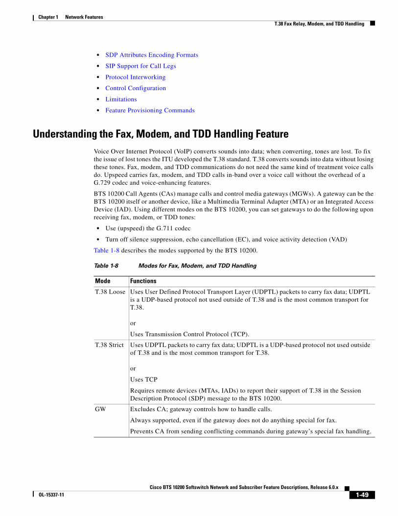
Chapter 1 Network FeaturesT.38 Fax Relay, Modem, and TDD Handling
• SDP Attributes Encoding Formats
• SIP Support for Call Legs
• Protocol Interworking
• Control Configuration
• Limitations
• Feature Provisioning Commands
Understanding the Fax, Modem, and TDD Handling FeatureVoice Over Internet Protocol (VoIP) converts sounds into data; when converting, tones are lost. To fix the issue of lost tones the ITU developed the T.38 standard. T.38 converts sounds into data without losing these tones. Fax, modem, and TDD communications do not need the same kind of treatment voice calls do. Upspeed carries fax, modem, and TDD calls in-band over a voice call without the overhead of a G.729 codec and voice-enhancing features.
BTS 10200 Call Agents (CAs) manage calls and control media gateways (MGWs). A gateway can be the BTS 10200 itself or another device, like a Multimedia Terminal Adapter (MTA) or an Integrated Access Device (IAD). Using different modes on the BTS 10200, you can set gateways to do the following upon receiving fax, modem, or TDD tones:
• Use (upspeed) the G.711 codec
• Turn off silence suppression, echo cancellation (EC), and voice activity detection (VAD)
Table 1-8 describes the modes supported by the BTS 10200.
Table 1-8 Modes for Fax, Modem, and TDD Handling
Mode Functions
T.38 Loose Uses User Defined Protocol Transport Layer (UDPTL) packets to carry fax data; UDPTL is a UDP-based protocol not used outside of T.38 and is the most common transport for T.38.
or
Uses Transmission Control Protocol (TCP).
T.38 Strict Uses UDPTL packets to carry fax data; UDPTL is a UDP-based protocol not used outside of T.38 and is the most common transport for T.38.
or
Uses TCP
Requires remote devices (MTAs, IADs) to report their support of T.38 in the Session Description Protocol (SDP) message to the BTS 10200.
GW Excludes CA; gateway controls how to handle calls.
Always supported, even if the gateway does not do anything special for fax.
Prevents CA from sending conflicting commands during gateway’s special fax handling.
1-49Cisco BTS 10200 Softswitch Network and Subscriber Feature Descriptions, Release 6.0.x
OL-15337-11

Chapter 1 Network FeaturesT.38 Fax Relay, Modem, and TDD Handling
MGCP/NCS InterfaceThe system supports the following fax procedures from the MGCP or NCS endpoint:
• T.38 loose mode (as defined by the FXR package).
• Cisco-proprietary gateway mode (not using the FXR package).
• Fax using existing audio media (fax pass-through)—The system does not support audio codec upspeeding in this case.
SDP Attributes Support for T.38 Fax RelayThe system supports the exchange of media path (SDP or H.245) attributes between the BTS 10200 managed end devices that support T.38. These attributes are:
• Capabilities attributes defined in RFC-3407 (which indicate the endpoint is T.38 capable)
• T.38 attributes defined in ITU-T T.38 Annex D. (These attributes negotiate T.38 properties between endpoints)
MTA DQOS Support for T.38 Fax RelayThere are DQOS considerations for NCS MTA subscribers when the call switches between audio and T.38 codec. The BTS 10200 follows the DQOS flow characteristics for T.38 sessions described in the PacketCable specification “pkt-sp-codec.”
For DQOS, the BTS 10200 creates new gates for the T.38 codec when the call switches to T.38 media, because endpoints can change their media IP and ports when switching between audio and T.38.
Fallback to Audio Media when T.38 Negotiation FailsThe system supports audio fallback on all interfaces supporting T.38 fax. Failure to negotiate T.38 media occurs when the non-fax detecting endpoint fails a request to modify the connection (MDCX) to T.38, and the MDCX contained a T.38 remote connection descriptor (SDP) from the fax-detecting end. When this occurs, a counter increments to track the event occurrences. Any other T.38 procedure fail scenarios do not trigger the fallback procedure. Instead, the call is cleared by the endpoint.
Audio fallback on T.38 negotiation failure requires collaboration by the endpoints. The MGCP/NCS endpoint requirements are:
• Non-Fax Detecting Endpoint
• Fax Detecting Endpoint
Non-Fax Detecting Endpoint
When the non-fax detecting endpoint fails the MDCX request to modify the connection to T.38, and this MDCX contained a T.38 remote connection descriptor (SDP) from the fax-detecting end, then the non-fax detecting endpoint continues with its current audio media settings.
1-50Cisco BTS 10200 Softswitch Network and Subscriber Feature Descriptions, Release 6.0.x
OL-15337-11

Chapter 1 Network FeaturesT.38 Fax Relay, Modem, and TDD Handling
Fax Detecting Endpoint
When the non-fax detecting endpoint fails a switch to T.38, the fax-detecting endpoint is still in T.38 media mode. The BTS 10200 sends an MDCX to the fax detecting endpoint to abort T.38 procedures and revert to previous audio media. The fax detecting endpoint responds with an audio SDP, and the BTS 10200 exchanges this SDP with the remote end.
The BTS 10200 applies the following recommendation, forecast as an update, to the MGCP FXR package. However, it does not send the “off” Fax LCO to abort T.38 procedures. Instead, it sends an “L:<previous codec>” LCO.
If a remote SIP endpoint or gateway sends a Re-Invite with T.38 SDP to switch to T.38 media, and receives a fail response, it should fall back to previous SDP settings.
For H.323 calls, if the non-H.323 endpoint fails to switch to T.38 fax while the H.323 side is already switched to T.38 fax, the H.323 side reapplies the H.245 procedure and returns to audio codec.
Audio Restore After Successful T.38 Fax TransmissionThe BTS 10200 can restore audio media after successful T.38 fax transmission. However, this feature is beyond the scope of the FXR package and requires collaborative support by the endpoints.
For the BTS 10200 to provide this feature, the MGCP/NCS endpoints must complete the following:
• Once the Cisco BTS 10200 Softswitch is notified of the completion of T.38 fax transmission, it sends an MDCX to the notifying endpoint to revert to previous audio media. The notifying endpoint responds with an audio SDP, and the BTS 10200 exchanges this SDP with the remote end.
• Remote SIP endpoints or gateways must send a Re-Invite message containing audio media SDP to restore audio.
T.38 Glare HandlingThe BTS 10200 applies a Call Agent-controlled switch to T.38 fax media when initiated by either the originating or terminating endpoint. This includes the scenario in which both endpoints initiate the switch, causing a glare condition at the BTS 10200.
For details about glare handling, contact your Cisco support representative.
SDP Attributes Encoding FormatsSDP capability attributes can be formatted either of the following two ways when the BTS 10200 sends the attribute information out of the network by means of MGCP, NCS and SIP protocols.
• RFC 3407 based encoding method. In this method, SDP is encoded:
a=sqn: 0 a=cdsc: 1 audio RTP/AVP 0 18 96a=cpar: a=fmtp:96 0-16,32-35 a=cdsc: 2 image udptl t38
• Cisco proprietary method. In this method, SDP is encoded:
a=X-sqn:0a=X-cap: 1 audio 0 18 96a=X-cpar: a=fmtp:96 0-16,32-35
1-51Cisco BTS 10200 Softswitch Network and Subscriber Feature Descriptions, Release 6.0.x
OL-15337-11

Chapter 1 Network FeaturesT.38 Fax Relay, Modem, and TDD Handling
a=X-cap: 2 image udptl t38
The BTS 10200 selects the encoding method based on the following guidelines:
• For the SIP interface, the BTS 10200 always performs encoding using the RFC 3407-based encoding method.
• For MGCP/NCS endpoints, the BTS 10200 uses a provisionable field to choose between the encoding methods.
• The H.323 interface does not use SDP, so this section is not applicable to H.323.
SIP Support for Call LegsThe system supports T.38 fax relay Call Agent-controlled mode to SIP lines and trunks where one or both call legs are SIP. In addition to passing the SDP advertisement of T.38 fax codec, the BTS 10200 issues a re-invite or similar SIP method to change the codec of an established session to a T.38 fax relay codec session once the fax event is detected (such as operating in a Call Agent-controlled mode).
This has a dependency on SIP CPEs and media gateways. We recommend that the T.38 session be initiated by the terminating endpoint.
For more information, refer to ITU T.38 03/2002.
Protocol InterworkingThe BTS 10200 supports T.38 for both SIP lines and SIP trunks, and interworking with the following protocols as either terminating or originating:
• MGCP line and trunk
• NCS (for cable)
• H.323 trunk
After the fax is done, the call falls back to a voice call.
The detailed protocol interworking matrix is shown in Table 1-9.
.
Figure 1-11 shows an example of MGCP and SIP interworking.
Table 1-9 Protocol Interworking Matrix
Protocol H.323 TrunkMGCP line (eMTA Using NCS) and Trunk SIP Line and Trunk
H.323 trunk X X X
MGCP line (eMTA using NCS) X X X
SIP line and trunk X X X
1-52Cisco BTS 10200 Softswitch Network and Subscriber Feature Descriptions, Release 6.0.x
OL-15337-11
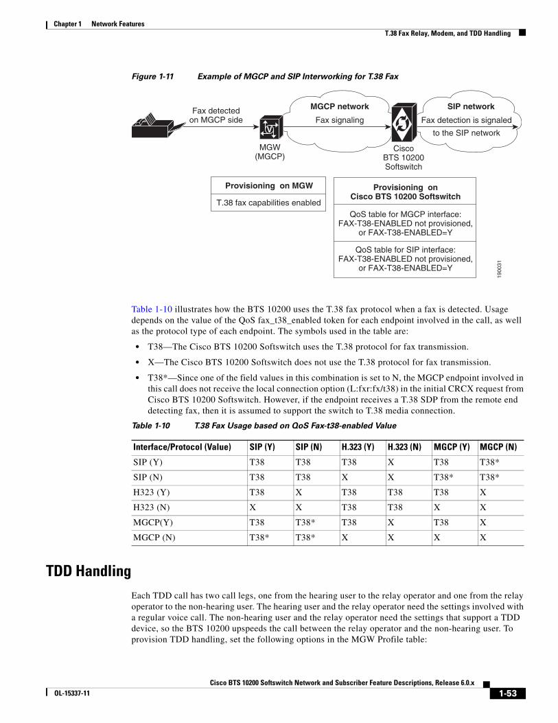
Chapter 1 Network FeaturesT.38 Fax Relay, Modem, and TDD Handling
Figure 1-11 Example of MGCP and SIP Interworking for T.38 Fax
Table 1-10 illustrates how the BTS 10200 uses the T.38 fax protocol when a fax is detected. Usage depends on the value of the QoS fax_t38_enabled token for each endpoint involved in the call, as well as the protocol type of each endpoint. The symbols used in the table are:
• T38—The Cisco BTS 10200 Softswitch uses the T.38 protocol for fax transmission.
• X—The Cisco BTS 10200 Softswitch does not use the T.38 protocol for fax transmission.
• T38*—Since one of the field values in this combination is set to N, the MGCP endpoint involved in this call does not receive the local connection option (L:fxr:fx/t38) in the initial CRCX request from Cisco BTS 10200 Softswitch. However, if the endpoint receives a T.38 SDP from the remote end detecting fax, then it is assumed to support the switch to T.38 media connection.
TDD HandlingEach TDD call has two call legs, one from the hearing user to the relay operator and one from the relay operator to the non-hearing user. The hearing user and the relay operator need the settings involved with a regular voice call. The non-hearing user and the relay operator need the settings that support a TDD device, so the BTS 10200 upspeeds the call between the relay operator and the non-hearing user. To provision TDD handling, set the following options in the MGW Profile table:
MGW(MGCP)
CiscoBTS 10200Softswitch
1900
31
SIP network
Fax detection is signaled
to the SIP network
MGCP network
Fax signalingFax detected
on MGCP sideV
Provisioning on MGW
T.38 fax capabilities enabled
Provisioning onCisco BTS 10200 Softswitch
QoS table for MGCP interface:FAX-T38-ENABLED not provisioned,
or FAX-T38-ENABLED=Y
QoS table for SIP interface:FAX-T38-ENABLED not provisioned,
or FAX-T38-ENABLED=Y
Table 1-10 T.38 Fax Usage based on QoS Fax-t38-enabled Value
Interface/Protocol (Value) SIP (Y) SIP (N) H.323 (Y) H.323 (N) MGCP (Y) MGCP (N)
SIP (Y) T38 T38 T38 X T38 T38*
SIP (N) T38 T38 X X T38* T38*
H323 (Y) T38 X T38 T38 T38 X
H323 (N) X X T38 T38 X X
MGCP(Y) T38 T38* T38 X T38 X
MGCP (N) T38* T38* X X X X
1-53Cisco BTS 10200 Softswitch Network and Subscriber Feature Descriptions, Release 6.0.x
OL-15337-11

Chapter 1 Network FeaturesT.38 Fax Relay, Modem, and TDD Handling
• TDD_TONE_SUPP to Y
• MODEM_TONE_SUPP to Y
• FAX_INBAND_METHOD to FT_UPSPEED
Control ConfigurationThe BTS 10200 can be configured with either Call Agent-controlled T.38 mode or gateway controlled T.38 mode.
LimitationsT.38 fax relay has the following limitations:
• BTS 10200 Unsupported T.38 Fax Transport Methods
• BTS 10200 Unsupported T.38 Interface
• MGCP/NCS Interface—T.38 Fax Modes Unsupported
• Call Waiting and Three Way Calling Limitations
• Limitations on End-to-End SDP Exchange for T.38 Media and the H.323 Interface
• Internet Fax Terminal Endpoint Types—Not Supported
• Limitations on BTS 10200 Handling of T.38 Failure Event Notification from an MGCP or NCS Endpoint
BTS 10200 Unsupported T.38 Fax Transport Methods
The BTS 10200 does not support the following T.38 fax transport methods from ITU-T T.38:
• TCP
• Fax over RTP
BTS 10200 Unsupported T.38 Interface
Support for ITU-T T.38 procedures is not provided on the following interfaces managed by the BTS 10200 (including the interworking between supported and unsupported interfaces):
• H.323 subscriber lines.
• CAS trunks.
MGCP/NCS Interface—T.38 Fax Modes Unsupported
The Cisco BTS 10200 Softswitch does not support the following MGCP FXR package defined T.38 fax modes from the MGCP/NCS endpoint:
• Gateway mode (though the Cisco-proprietary Gateway mode is supported)
• Off mode
1-54Cisco BTS 10200 Softswitch Network and Subscriber Feature Descriptions, Release 6.0.x
OL-15337-11

Chapter 1 Network FeaturesT.38 Fax Relay, Modem, and TDD Handling
If the BTS 10200 does not signal any FXR fax mode in the Local Connection Options, including “Off” mode, the gateway can engage in Gateway mode. If this occurs, the BTS 10200 does not receive any Gateway mode notification events from the endpoint because it does not request them. The BTS 10200 is not notified of the gateway mode activity. The BTS 10200 honors the FXR package requirements during gateway mode by not interfering with the gateway procedures in this case.
Call Waiting and Three Way Calling Limitations
We recommend that BTS 10200 subscribers disable the Call Waiting feature before making a call for fax transmission. This protects against any interruptions during fax transmission.
In certain multi-party call feature scenarios, such as three-way calling where a user has engaged the three-way call feature on the BTS 10200 and one party attempts a switch to T.38 fax, the endpoint fails to switch the call to T.38. The party can be either disconnected or switched back to audio depending on the endpoint capabilities.
The BTS 10200 makes no distinction with respect to call features between calls using audio and calls using fax transmission.
Limitations on End-to-End SDP Exchange for T.38 Media and the H.323 Interface
The H.323 protocol must negotiate T.38 fax connection attributes (example: bit rate, maximum buffer size) during the voice call establishment using Terminal Capability Set (TCS) messages. However, for SIP and MGCP, the endpoint does not report T.38 fax connection attributes until the fax actually starts. When this occurs from an interworking H.323 endpoint and a SIP/MGCP interface, and the H.323 endpoint is ready to send a TCS message during the voice call establishment phase, the T.38 fax attributes are not available from the SIP/MGCP interface.
To overcome this interworking limitation, all Cisco IOS gateways take on the defaults for these attributes while exchanging TCS messages. The BTS 10200 follows the same philosophy for H.323 to/from MGCP/NCS and H.323 to/from SIP calls. The BTS 10200 assumes the following defaults:
• Maximum Bit Rate = 14.4 kbps. This can be configured in the T38_MAX_BIT_RATE field in the CA_CONFIG table.
• Fill Bit Removal = false.
• MMR Transcoding = false.
• JBIG Transcoding = false.
• Data Rate Management Method = transferredTCF.
• Maximum Buffer Size = 200. This can be configured in T38_MAX_BUFFER_SIZE field in CA_CONFIG table.
• Maximum Datagram Size = 72. This can be configured in T38_MAX_DATAGRAM_SIZE field in the CA_CONFIG table.
• Error Correction = t38UDPRedundancy.
To overcome other interworking limitations with SIP, IOS H.323 gateways send the fax UDP port in H.245 Open Logical Channel (OLC) messages. A provisioning field (REMOTE_FAX_PORT_ RETRIEVAL_MSG) is added in h323-tg-profile and h323-term-profile, enabling the H.323 interface to read a remote endpoint’s fax UDP port either from OLC message or from OLC Ack message. (This does not apply to T.38 fax transmissions across H.323-to-H.323 calls on the BTS 10200. In this case, the H.245 messages are exchanged directly through the BTS 10200.)
1-55Cisco BTS 10200 Softswitch Network and Subscriber Feature Descriptions, Release 6.0.x
OL-15337-11

Chapter 1 Network FeaturesTrunk and Line Testing
Internet Fax Terminal Endpoint Types—Not Supported
The BTS 10200 does not support endpoints that negotiate for T.38 media on initial call setup. These endpoints include internet fax terminals or internet-aware fax devices, and internet telephony gateways that only support T.38 real-time fax communications (by design or by configuration), or are statically configured to support T.38 fax calls only.
Limitations on BTS 10200 Handling of T.38 Failure Event Notification from an MGCP or NCS Endpoint
The BTS 10200 releases the call if the MGCP or NCS fax-detecting endpoint issues a “t38(failure)” event. This event is sent by the endpoint when it encounters a problem with the T.38 fax relay procedure, as stated in the MGCP FXR package.
Feature Provisioning Commands
To provision this feature, see the T.38 Fax Relay provisioning procedure in the Provisioning Guide.
Trunk and Line TestingThis section describes trunk and line testing features, and includes the following topics:
• Trunk Testing, page 1-56
• Testing Capability for 911 FGD-OS Trunks, page 1-58
• Network Loopback Test for NCS/MGCP Subscriber Endpoints, page 1-59
• Network Loopback Test for ISDN PRI Trunks, page 1-59
For general troubleshooting procedures, see the Troubleshooting Guide.
Trunk TestingTrunk testing is used to evaluate the transmission quality of the shared trunks that interconnect switching systems. Trunk testing is extremely important in monitoring system health, because it is the only practical way to objectively evaluate the performance of individual trunks.
Trunk testing requires the following equipment and test lines. (Some additional types of equipment and lines can also be used.) A basic system setup is shown in Figure 1-12.
• Test controller
• Test set(s)
• Originating test line (OTL)
• Terminating test line (TTL)
1-56Cisco BTS 10200 Softswitch Network and Subscriber Feature Descriptions, Release 6.0.x
OL-15337-11

Chapter 1 Network FeaturesTrunk and Line Testing
Figure 1-12 Trunk Testing Setup
Near End Test Origination Test Calls
The BTS 10200 supports calls used to test individual trunks that connect a local gateway with a gateway or PSTN switch at a remote office. The BTS 10200 supports OTL and TTL capability. User-provided test equipment and, optionally, test controllers can be connected to the test lines. Proper selection of test equipment and test functions helps to ensure interoperability between different carriers.
The processes described in this section are applicable to the BTS 10200. The processes might work differently on other switches.
The process for testing a BTS 10200 OTL is as follows:
1. The user verifies that the remote CO has the desired 1xx test line available.
2. The user sets up a test device on a CAS TGW that is connected to the local BTS 10200.
3. The user provisions the CAS-TG-PROFILE table, setting TEST-LINE = YES. (Provisioning commands are described in the Cisco BTS 10200 Softswitch CLI Database.)
4. On the test device at the CAS TGW side, the user enters digits representing the circuit to be tested and the test to be performed:
– TG, for example 0003
– Trunk number, for example 0018
The complete trunk address in this example is 00030018.
– Test type (10x), for example 104
The technician dials KP-00030018-104-ST.
5. The BTS 10200 automatically inserts either 9581 or 9591 in front of the test type digits to create a dialing string.
The complete test string in this example is PREFIX | 00030018 | 9581104 | END.
Note Alternatively, with the BTS 10200, the user can dial the test type with the 9581 or 9591 included: KP-00030018-9581104-ST.
6. The BTS 10200 selects the trunk to be tested based on the user-defined trunk address.
7. The TGW outpulses the digits to the remote switch over the designated trunk.
Test controller
Test setOTL
Selection link(optional)
Near endswitch
TTLTest set
Trunk under test
Controllink
Trunk group
Far endswitch
7616
9
1-57Cisco BTS 10200 Softswitch Network and Subscriber Feature Descriptions, Release 6.0.x
OL-15337-11
Chapter 1 Network FeaturesTrunk and Line Testing
1xx Test Line Support
When the BTS 10200 is the near-end switch, the following process takes place at the remote switch:
1. The remote switch recognizes the trunk test prefix (9581 or 9591) on the incoming signal, and it uses the test type to route the test to the appropriate test line.
2. The appropriate tests are performed on the test set.
3. Additional test processes may be used, depending on the specific test configuration.
When the BTS 10200 is supporting the TTL capability (test call originated at another switch), the BTS 10200 receives the 958 or 959 call, recognizes the 958 or 959 type, and routes the test to the appropriate test line.
The BTS 10200 enables a TDM-based testing device to perform continuity testing over an MF CAS TDM trunk interface. An MGCP-based trunking gateway must be present in the test path. The TDM test type is the traditional 1xx test type, with an additional enhancement—the ability to route the test call to a specified DN on a given trunk circuit.
T108 Test Line Support
The T108 test line feature determines the performance of trunks connecting digital exchange switches, including voice over packet (VoP) softswitches. BTS 10200 incoming trunks requesting other 1xx-type test lines are routed to shared test lines for the requested tests, regardless of which gateway terminates the trunk or which gateway/IAD terminates the test line. The T108 test line feature requests a test to be performed within the same gateway where the trunk under test (TUT) is terminated, and provides a digital loopback within the gateway. The T108 test line feature supports manual and automated testing.
The T108 test line sequence is as follows:
1. The near-end switch originates the test sequence by placing a test call, identifying the trunk to be selected, and the test line number. A digital test pattern generator is used in the test setup shown in Figure 1-12.
2. The near-end switch uses the trunk identifier to override normal call processing and select only the requested trunk.
3. The far-end switch responds to the destination number and connects to the T108 test line. The T108 test line enables a digital loopback.
4. When the near-end switch receives answer supervision, it conducts digital test sequences to ascertain trunk performance.
5. Once the test sequences are completed, the near-end switch releases the test call and both switches release the trunk connection.
6. The far-end switch can detect if the test connection exceeds a preset time and releases the test connection if the preset time is exceeded.
The T108 test line is also used for trunk redirection (wholesale dial) for Internet services where the carrier modem termination is integrated into the trunk gateway. In this case, the integral digital stored program (DSP) normally supports modem-only transmissions.
Testing Capability for 911 FGD-OS TrunksWhen turning up 911 Feature Group D Operator Services (FGD-OS) trunks, there is an exchange of off-hook/on-hook signaling and the passing of tone back and forth without a complete call setup. Signaling for this function is based on the MGCP MO package.
1-58Cisco BTS 10200 Softswitch Network and Subscriber Feature Descriptions, Release 6.0.x
OL-15337-11

Chapter 1 Network FeaturesTrunk and Line Testing
Upon receiving a CLI command or Test Access request, the BTS 10200 sends the request to the gateway by means of MGCP signaling to trigger the test capability on the 911 trunk at the gateway (not part of a call setup sequence). The BTS 10200 reports the result to the operator upon receiving the notification from the gateway (for example, receiving off-hook or on-hook notification). Once this gateway test capability on a 911 trunk is in place, it can be invoked remotely across the MGCP interface associated with the BTS 10200.
Note In order to support this function, the gateway itself must be able to provide the test capability to send and monitor the reception of the signaling and passing tone without a call setup involvement.
Network Loopback Test for NCS/MGCP Subscriber EndpointsThis feature enables a testing device to perform network loopback tests from any line-side NCS/MGCP Residential Gateway or MTA. The loopback tests can be initiated from designated test endpoints (subscribers) controlled by the BTS 10200. The procedure for setting up the test includes configuring the test lines as subscriber terminations and provisioning the MGW parameters. The system allows NCS/MGCP endpoints in a trunk group to be provisioned as a test trunk group with specific test attributes.
Restrictions and Limitations
The following restrictions and limitations apply:
• The testing and tested devices must be configured on the same Call Agent. The system cannot perform network loopback test calls that originate from another switch.
• The system does not provide the ability to perform network loopback testing across H.323 or SIP networks.
• You cannot perform the Network Loopback Test if the status of the subscriber to be tested is unequipped (UEQP) or operational-out-of-service (OOS).
• Although you can test this feature using a regular MTA as the testing device by configuring the endpoints as subscriber terminations in the BTS 10200, you need appropriate test equipment to perform voice-quality testing.
Configuring and Operating
The procedures for configuring the lines and gateways and the procedure for performing the tests are described in the “Network Loopback Test” section of the Troubleshooting Guide.
Network Loopback Test for ISDN PRI TrunksThis feature allows operators to conduct network loopback testing originating from shared ISDN PRI trunks. The shared test trunk group accepts both normal and test calls. Test calls are identified by provisioning the call-type and call-subtype tokens in the Destination table.
For detailed requirements and procedures for running this type of trunk test, see the “ISDN Network Loopback Test” section in the Troubleshooting Guide.
1-59Cisco BTS 10200 Softswitch Network and Subscriber Feature Descriptions, Release 6.0.x
OL-15337-11

Chapter 1 Network FeaturesSh Interface
Sh InterfaceThis section describes the Sh interface between the Cisco BTS 10200 Softswitch acting as a Telephony Application Server (TAS) and a Home Subscriber Server (HSS). This document applies to BTS 10200 Release 6.0 MR1. It includes the following topics:
• Understanding the Sh Interface
• Limitations
Understanding the Sh InterfaceHSS is an external database that stores BTS 10200 TAS subscriber profiles. HSS does not handle calls, but supports IP Multimedia Subsystem (IMS) network entities (like BTS 10200 and other switches) that do. HSS uses the subscriber profiles to locate subscribers. The BTS 10200 and HSS interact as follows:
1. An operator provisions TAS subscriber profiles on the BTS 10200.
2. The BTS 10200 stores the TAS subscriber profiles in its own databases on the Element Management System (EMS) and Call Agent (CA) or Feature Server (FS). These are the database tables:
– Emergency ANI
– HSS Public ID
– Screen List Editing (SLE)
– Single Number Reach (SNR)
– SIP Trigger Profile
– Speed Call: 1-Digit (SC1D)
– Speed Call: 2-Digit (SC2D)
– Subscriber
– Subscriber Feature Data
– Subscriber Service Profile
– Subscriber Time-Of-Day Schedule
3. The BTS 10200 pushes updated subscriber data to the HSS when either of the following occurs:
– An operator enters commands to retrieve, add, change, or delete subscriber data.
– A TAS subscriber uses their handset to control their calling features.
The BTS 10200 is the master database for subscribers. Provisioned subscriber data is saved in the BTS10200 first, then pushed to HSS for storage.
When the HSS is unreachable, you can still provision on the BTS 10200. The BTS 10200 queues transactions and when HSS becomes available, the BTS 10200 pushes the queued data to the HSS.
Table 1-11 describes the kind of subscriber data Sh requests by the BTS 10200 return.
Table 1-11 Subscriber Data from Sh Requests
Name Description
Repository data Transparent service data
Public identifiers Subscriber’s Public User Identities (PUIs)
1-60Cisco BTS 10200 Softswitch Network and Subscriber Feature Descriptions, Release 6.0.x
OL-15337-11

Chapter 1 Network FeaturesSh Interface
BTS 10200 and HSS CommunicationsThe HSS and BTS 10200 communicate using the Sh interface over the Diameter protocol. Diameter is a peer-to-peer protocol. The HSS and BTS 10200 communicate about subscriber data as follows:
• BTS 10200 queries subscriber profiles stored on the HSS.
• BTS 10200 registers/deregisters for subscriber profile updates.
• BTS 10200 updates subscriber profiles stored on the HSS.
• HSS notifies BTS 10200 when subscriber profiles change on the HSS.
The BTS 10200 generates and responds to Diameter command codes. Diameter uses these command codes to identify its message types.
The BTS 10200 connects to more than one HSS as a Diameter peer:
• Priority based—Primary and secondary HSSs mean all Diameter requests go to the primary. If the primary goes down, all requests go to the secondary.
• Round Robin—BTS 10200 sends Diameter requests evenly between operational HSSs.
Sh Interface CommandsThe Sh interface operates in data handling mode or subscription/notification mode.
• Data handling is performed by a:
– Sh Pull request (Sh-Pull)—Retrieves data from the HSS
– Sh Update request (Sh-Update)—Sends data to the HSS
• Subscription/Notification (Sh-SubNotif) subscribes the BTS 10200 to get notified by the HSS when subscriber data updates.
• Notification (Sh-Notif) notifies the BTS 10200 when subscriber data is updated on the HSS by other network entities.
Each time the BTS 10200 requests access to subscriber data, the HSS uses a list to verify it has permission. HSS manages permissions using Sh-Pull, Sh-Update, and Sh-SubNotif. For example, the BTS 10200 may have permission to perform Sh-Pull, but not Sh-Update.
Table 1-12 describes Sh interface commands used to manage subscribers between the BTS 10200 and HSS.
IMS User State not supported in current release
S-CSCF Name not supported in current release
Initial Filter Criteria not supported in current release
Location Information not supported in current release
User State not supported in current release
Charging information not supported in current release
MSISDN not supported in current release
Name Description
1-61Cisco BTS 10200 Softswitch Network and Subscriber Feature Descriptions, Release 6.0.x
OL-15337-11

Chapter 1 Network FeaturesSh Interface
Table 1-12 Sh Interface Commands by Pair
BTS 10200 ClusteringClustering (grouping) BTS 10200s improves service availability and allows you to be flexible in provisioning subscribers and features. In a cluster, each BTS 10200 serves its own subscribers. Clustering requires no special provisioning, it is simply a matter of how you organize your network.
You can move some or all of these subscribers to another BTS 10200 in the cluster during a planned migration or disaster recovery. Because each BTS 10200 stores its subscriber data in the HSS, during migration or disaster recovery, the destination BTS 10200 pulls subscriber data from the HSS.
See Moving Subscriber Groups from BTS 10200 to BTS 10200 section in the Cisco BTS 10200 Softswitch Provisioning Guide for more information.
Each BTS 10200 has its own BTS-id. This BTS-id is checked against the subscriber group owner to determine whether that BTS 10200 owns the subscriber. To update a subscriber’s data, make changes on the BTS 10200 that owns the subscriber’s public-ID. Other BTS 10200s have read-only access to each other’s subscribers. However, a subscriber with the handset provisioning feature can update their data via any BTS 10200 in the cluster.
Command Originator Description Response
User-Data-Request (UDR)
BTS 10200 This command requests data for a subscriber. UDA
User-Data-Answer (UDA)
HSS This command is a response to UDR. N/A
Command Originator Description Response
Profile-Update-Request (PUR)
BTS 10200 This command updates subscriber data. PUA
Profile-Update-Answer (PUA)
HSS This command is a response to PUA. N/A
Command Originator Description Response
Subscribe-Notifications-Request (SNR)
BTS 10200 This command subscribes/unsubscribes for notifications when a subscriber's information changes.
SNA
Subscribe-Notification-Answer (SNA)
HSS This command is a response to SNR. N/A
Command Originator Description Response
Push-Notification-Request (PNR)
HSS This command sends subscriber data changes to the BTS 10200.
PNA
Push-Notification-Answer (PNA)
BTS 10200 This command is a response to PNR. N/A
1-62Cisco BTS 10200 Softswitch Network and Subscriber Feature Descriptions, Release 6.0.x
OL-15337-11

Chapter 1 Network FeaturesTelephony Application Server
Limitations Release 6.0 MR1 of the BTS 10200 only supports HSS interaction for TAS subscribers; it does not support the following subscriber types:
• Cable (MTA)
• Centrex Group
• H.323
• ISDN
• IVR’s access DN for IVR
• MGCP (IAD)
• MLHG
• NCS
• PBX
• Remote Call Forwarding’s (RCF’s) virtual subscribers
• Remote Activation of Call Forwarding’s (RACF’s) access DN
• SIP (non-TAS)
Note The transaction queue HDM process must be fully initialized before the CLI/CPM/CPI processes can write HSS requests into TRANSACTION_QUEUE table for BTS-to-HSS requests. In case when platform has just started or re-started, if the user requests some BTS-to-HSS commands, the commands will fail in the time elapse when the HDM process is not fully initialized. The HDM process takes some time to fully initialize.
For information on measurements of this feature, see the Cisco BTS 10200 Softswitch Operation and Maintenance Guide.
For information on provisioning this feature, see the Cisco BTS 10200 Softswitch Provisioning Guide.
For troubleshooting information, see the Cisco BTS 10200 Softswitch Troubleshooting Guide.
Telephony Application ServerThe Telephony Application Server (TAS) TAS application allows the BTS 10200 to communicate with serving call session control function (S-CSCF) servers over an IP multimedia service control (ISC) interface to provide subscriber calling features. The TAS can perform origination processing and termination processing; it can also route calls if requested by the originating S-CSCF. The TAS and the S-CSCF are both SIP-based applications. (The S-CSCF is external to the BTS 10200.)
1-63Cisco BTS 10200 Softswitch Network and Subscriber Feature Descriptions, Release 6.0.x
OL-15337-11
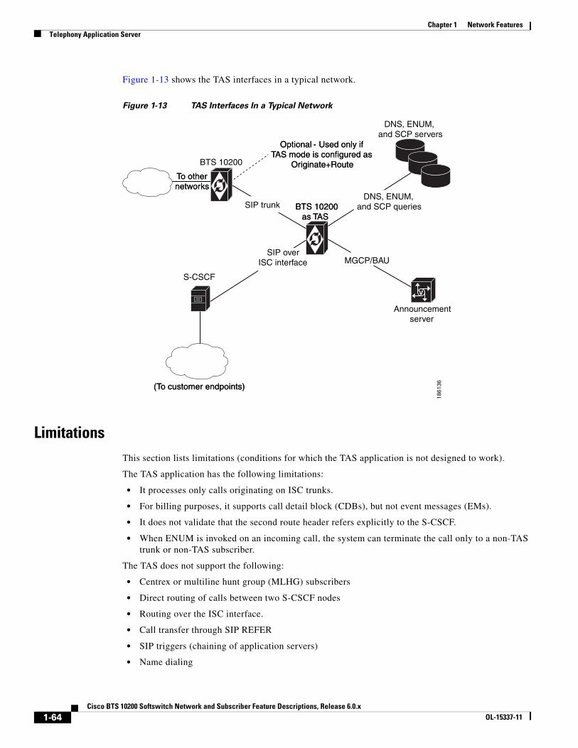
Chapter 1 Network FeaturesTelephony Application Server
Figure 1-13 shows the TAS interfaces in a typical network.
Figure 1-13 TAS Interfaces In a Typical Network
LimitationsThis section lists limitations (conditions for which the TAS application is not designed to work).
The TAS application has the following limitations:
• It processes only calls originating on ISC trunks.
• For billing purposes, it supports call detail block (CDBs), but not event messages (EMs).
• It does not validate that the second route header refers explicitly to the S-CSCF.
• When ENUM is invoked on an incoming call, the system can terminate the call only to a non-TAS trunk or non-TAS subscriber.
The TAS does not support the following:
• Centrex or multiline hunt group (MLHG) subscribers
• Direct routing of calls between two S-CSCF nodes
• Routing over the ISC interface.
• Call transfer through SIP REFER
• SIP triggers (chaining of application servers)
• Name dialing
(To customer endpoints)
SIP over ISC interface
Announcementserver
MGCP/BAU
SIP trunk
To othernetworks
BTS 10200as TAS
Optional - Used only if TAS mode is configured as
Originate+Route
(To customer endpoints)
S-CSCF
SIP over ISC interface MGCP/BAU
SIP trunk
To othernetworks
BTS 10200as TAS
DNS, ENUM, and SCP servers
Optional - Used only if TAS mode is configured as
Originate+RouteBTS 10200
DNS, ENUM, and SCP queries
V
1861
36
1-64Cisco BTS 10200 Softswitch Network and Subscriber Feature Descriptions, Release 6.0.x
OL-15337-11

Chapter 1 Network FeaturesTelephony Application Server
• Operator and emergency services—Busy line verification (BLV), operator interrupt (OI) and 911 callback
• The following REQ-URI features: E.164 formatting, dial-around indicator, calling party category, nature of address, and carrier identification code)
• P-Called-Party header
Origination ProcessingThe TAS application provides origination processing (also called origination services) based on a request it receives from the S-CSCF over the ISC interface. The TAS application processes the origination request from the S-CSCF and then returns the call to the S-CSCF. The S-CSCF determines whether the call requires further processing by the TAS and can send a new request to the TAS.
Figure 1-14 shows an example of how the TAS responds to an S-CSCF origination request, in this case an origination request with a toll-free dialed DN.
Figure 1-14 Example of Origination Request—Origination of Toll-Free Call
The process shown in Figure 1-14 is as follows:
1. The S-CSCF sends the origination request to the TAS, including the public ID of the caller and the dialed DN. The Invite message contains the following routing headers:
– Route: sip:orig@tas;lr
– Route: sip:scscf@scscf:5210;lr
2. The TAS matches the public ID of the caller to a subscriber ID in the BTS 10200 internal database. In addition, the TAS translates the dialed DN digits according to the dial plan provisioned for the originating subscriber and determines the type of call. (The TAS includes the call type in the billing record for the call.)
3. If necessary, the TAS queries the local Domain Name System (DNS) server or external ENUM server in the process of translating the public ID. In addition, the TAS queries the external Service Control Point (SCP) in the process of translating the toll-free DN.
BTS 10200as TAS
SIP over ISC interface
DNSserver
External ENUMserverBTS 10200
as TAS
SIP over ISC interface
ExternalSCP
Originating line18
6137
321
5
4S-CSCF
1-65Cisco BTS 10200 Softswitch Network and Subscriber Feature Descriptions, Release 6.0.x
OL-15337-11

Chapter 1 Network FeaturesTelephony Application Server
4. The TAS performs class of service (COS) screening to determine whether this subscriber is allowed to initiate this type of call.
– The TAS returns the call, along with the translated digits and COS screening results, to the S-CSCF. The Invite message contains the routing header Route: sip:scscf@scscf:5210;lr.
(The S-CSCF is responsible for continuing with routing and call setup.)
Note The S-CSCF can use the TAS to provide origination processing even if the call does not invoke any specific calling features from the TAS. For example, the S-CSCF might require digit translation for a dialed DN, but no other processing from the TAS.
Table 1-3 describes the level of support provided to TAS subscribers on originating calls that the BTS 10200 receives on the ISC interface.
Table 1-13 Support for TAS Subscribers On Originating Calls
Originating Feature Abbreviation Support for TAS Subscribers
Vertical Service Codes (VSCs):
• Activation, deactivation, and interrogation features, including the use of VSCs, for example CBLK, CFUA, CFBI, CNAB, CNDB, DND_ACT, and DND_DEACT.
• VSCs dialed to access feature management functions, for example PS_MANAGE, PS_O, CIDSD, CIDSS, VM_ACCESS.
(various) For MGCP and NCS endpoints, the system collects digits in two stages.
For SIP-based endpoints (including TAS subscribers), the VSC and any additional digits (such as a forward-to DN) are collected by the S-CSCF. The S-CSCF aggregates the VSC and all of the additional collected digits, and then presents them to the TAS at a single event during call setup.
Toll Free 8xx Origination processing is supported for TAS subscribers.
Emergency Service 911 Only E911 support (without called-party control) is provided. Basic 911 with suspend procedure is not supported.
Automatic Callback AC Not supported for TAS subscribers.
Automatic Recall AR Not supported for TAS subscribers.
Class of Service COS Origination processing is supported for TAS subscribers. However account and authorization code functions are not supported.
Customer Originated Trace COT Not supported for TAS subscribers.
Call Transfer CT This is a SIP endpoint feature, not a feature of TAS.
Hotline HOTLINE Not supported for TAS subscribers.
Hotline Variable HOTV Not supported for TAS subscribers.
Limited Call Duration LCD Not supported for TAS subscribers.
Outgoing Call Barring OCB Origination processing is supported for TAS subscribers.
Speed Call - 1 /2 digit SC1D
SC2D
Not supported for TAS subscribers.
1-66Cisco BTS 10200 Softswitch Network and Subscriber Feature Descriptions, Release 6.0.x
OL-15337-11

Chapter 1 Network FeaturesTelephony Application Server
Termination ProcessingThe TAS application provides termination processing (also called termination services) based on a request it receives from the S-CSCF over the ISC interface. The TAS application processes each termination request from the S-CSCF and then returns the call to the S-CSCF. The S-CSCF determines whether the call requires further processing by the TAS and can send a new request to the TAS
If a terminating subscriber has a call-forwarding feature (for example, CFU, CFB, CFNA, or CFC) active on the subscriber line, the TAS application does not automatically attempt to route the call to the forward-to DN. Instead, the TAS returns the subscriber termination information (including the call-forwarding data) to the S-CSCF for processing. Subsequently, the S-CSCF has the option of sending a new origination request to the TAS based on the forward-to DN.
Figure 1-15 shows an example of how the TAS responds to an S-CSCF termination request, in this case the termination of an incoming call to a busy line with CFB assigned and active.
Figure 1-15 Example of Termination Request—Termination of Incoming Call to Busy Line
The process shown in Figure 1-15 is as follows:
1. The S-CSCF sends the termination request to TAS, including the public ID of the called party (the terminating subscriber line). The Invite message contains the routing header Route: sip:scscf@scscf:5210;lr.
Three Way Call TWC This is a SIP endpoint feature, not a feature of TAS.
Three Way Call Deluxe TWCD This is a SIP endpoint feature, not a feature of TAS.
Usage Sensitive Three Way Call USTWC This is a SIP endpoint feature, not a feature of TAS.
Warmline WARMLINE Not supported for TAS subscribers.
Table 1-13 Support for TAS Subscribers On Originating Calls (continued)
Originating Feature Abbreviation Support for TAS Subscribers
BTS 10200as TAS
SIP over ISC interface
DNSserver
External ENUMserverSIP over
ISC interface
Terminating line(CFB active, line is busy)
1861
38
3
2
1
6
85
4
7
S-CSCF
1-67Cisco BTS 10200 Softswitch Network and Subscriber Feature Descriptions, Release 6.0.x
OL-15337-11

Chapter 1 Network FeaturesTelephony Application Server
2. The TAS matches the public ID of the called party to a subscriber ID in the BTS 10200 internal database.
3. If necessary, the TAS queries the local DNS server or external ENUM server in the process of translating the public ID.
4. The TAS returns the call to the S-CSCF with the public ID unchanged.
5. The S-CSCF attempts to terminate the call to the called party. However, the called party is busy, and the call cannot be completed.
6. The S-CSCF sends a 486 message (Busy Here) to the TAS.
7. The TAS determines that the subscriber has CFB assigned and active to a specific forward-to DN, and looks up the public ID associated with the forward-to DN.
8. The TAS sends the call back to the S-CSCF with this new public ID. The TAS also sends the original SIP headers that were part of the incoming call.
The S-CSCF is responsible for continuing with routing and call setup. For example, the S-CSCF might return the call to the TAS as a new originating request directed to the forward-to DN.
The TAS includes an acknowledgement of the CFB treatment in the billing record for the call.
Note The S-CSCF can use the TAS to provide termination processing even if the call does not invoke any specific calling features from the TAS.
Table 1-4 describes the level of support provided to TAS subscribers on terminating calls.
Table 1-14 Support for TAS Subscribers On Terminating Calls
Terminating Feature Abbreviation Support for TAS Subscribers
Anonymous Call Rejection ACR Termination processing is supported for TAS subscribers.
Busy Line Verification BLV Not supported for TAS subscribers.
Call-Forwarding-Busy/Call-Forward-No-Answer/Call Forwarding Combined/Call-Forwarding-Unconditional - Invocation
CFB/CFNA/CFC/CFU
Invocation
Termination processing is supported for TAS subscribers.
Calling Identity Delivery on Call Waiting
CIDCW This is a SIP endpoint feature, not a feature of TAS.
Calling Name Delivery CNAM Termination processing is supported for TAS subscribers. 1
Calling Number Delivery CND The the calling number is always delivered to the application server, even if the CND feature is disabled for the subscriber; this treatment is provided because the application server is a trusted entity. However, if CNAM is disabled for the subscriber, the system does not send the calling name nor the calling number.
Call Waiting CW This is a SIP endpoint feature, not a feature of TAS.2
Call Waiting Deluxe CWD This is a SIP endpoint feature, not a feature of TAS.2
Distinctive Alerting Call Waiting Indication
DACWI This is a SIP endpoint feature, not a feature of TAS.2
Do Not Disturb DND Termination processing is supported for TAS subscribers.
1-68Cisco BTS 10200 Softswitch Network and Subscriber Feature Descriptions, Release 6.0.x
OL-15337-11

Chapter 1 Network FeaturesTelephony Application Server
The CNAM rules for calls terminating to TAS subscribers are shown in Table 1-15. In this table, TAS action refers to the SIP headers that appear in the incoming and outgoing INVITE. Pass through means that the values are preserved from the incoming to the outgoing INVITEs.
Distinctive Ringing Call Waiting DRCW Termination processing of the ringing part is supported for TAS subscribers. The TAS sends a unique alerting indication to the SIP endpoint. The endpoint plays the ring tone if it is capable of interpreting the alerting indication from the TAS.
For the call-waiting scenario, the TAS processes the alerting request. Some SIP endpoints are capable of delivering the distinctive call-waiting tone, and others are not.
Local Number Portability LNP Termination processing is supported for TAS subscribers. The TAS performs an LNP query if the dialed number matches a digit string provisioned in the ported_office_code table.
Multiple Directory Number MDN Termination processing of the ringing part is supported for TAS subscribers. The TAS informs the S-CSCF of the specific ring type to apply. You provision the ring types in the bts-public-id table.
Call waiting is not applicable to TAS.
No Solicitation Announcement NSA Not supported for TAS subscribers.
Privacy Screening PS Not supported for TAS subscribers.
Remote Activation of Call Forwarding
RACF Termination processing is supported for TAS subscribers. You must provision a UAN domain name for this feature in the feature_config table.
Remote Call Forwarding RCF Not supported for TAS subscribers.
Selective Call Acceptance/Selective Call Forwarding/Selective Call Rejection
SCA/SCF/SCR Termination processing is supported for TAS subscribers.
1. See the CNAM rules in Table 1-15.
2. Call waiting function is not supported for TAS calls.
Table 1-14 Support for TAS Subscribers On Terminating Calls (continued)
Terminating Feature Abbreviation Support for TAS Subscribers
Table 1-15 CNAM Rules for Terminating Calls
TAS Mode Name Available TAS Action
Orig or Orig+Route N Pass through the From and PAID1 headers.
1. PAID = P-Asserted Identity
Orig or Orig+Route Y Pass through the From and PAID headers.
Term N Mark From hostname as anonymous, delete From user part, display name and PAID header in their entirety.
Term N (but forwarding has occurred)
Pass through the user name and PAID header in their entirety.
Term Y Pass through user name and host on the From and PAID headers. Set Display name on From and PAID based on the CNAM feature.
1-69Cisco BTS 10200 Softswitch Network and Subscriber Feature Descriptions, Release 6.0.x
OL-15337-11

Chapter 1 Network FeaturesTelephony Application Server
Origination + Routing ProcessingIf the S-CSCF requests the TAS to perform origination + routing processing, the TAS provides origination processing, then routes the call according to the dial plan provisioned for the originating line.
Figure 1-16 shows how the TAS responds to an S-CSCF origination + routing request, in this case an origination + routing request with OCB screening.
Figure 1-16 Example of Origination + Routing Request—Call with OCB Screening
The process shown in Figure 1-16 is as follows. Note that Steps 1 through 3 are the same as Steps 1 through 3 in the “Origination Processing” section on page 1-65.
1. The S-CSCF sends the origination request to the TAS, including the public ID of the caller and the dialed DN.
2. The TAS matches the public ID of the caller to a subscriber ID in the BTS 10200 internal database. In addition, the TAS translates the dialed DN digits according to the dial plan provisioned for the originating subscriber and determines the type of call. (The TAS includes the call type in the billing record for the call.)
3. If necessary, the TAS queries the local Domain Name System (DNS) server or external ENUM server in the process of translating the public ID. In addition, the TAS queries the external Service Control Point (SCP) in the process of translating the toll-free DN.
4. The TAS performs COS and OCB screening to determine whether this subscriber is allowed to initiate this type of call.
5. The TAS routes the call according to the dial plan provisioned for the originating line. Examples are shown in Figure 1-16 for
– Path labeled 5A—If the terminating party is served by the same S-CSCF as the originating line, the TAS routes the call over the ISC interface to the S-CSCF.
– Path labeled 5B—If the terminating party is on another network, the TAS routes the call over a SIP trunk connected to an external media gateway controller (MGC) component or a call management server (CMS) component. The MGC and/or CMS can run on a separate BTS 10200 system.
BTS 10200as TAS
SIP over ISC interface
DNSserver
External ENUMserverBTS 10200
as TAS
ExternalSCP
S-CSCF
Originating line
1861
39
31
5A
5B
SIP over
To othernetwoks
ISC interface
BTS 10200as MGC/CMS
24
1-70Cisco BTS 10200 Softswitch Network and Subscriber Feature Descriptions, Release 6.0.x
OL-15337-11

Chapter 1 Network FeaturesTelephony Application Server
Certain SIP messaging takes place when the TAS routes a call. The TAS operates as a B2BUA. It receives the call from the S-CSCF on the ISC interface. The top-most Route header must correspond to the TAS and there must be one other Route header (corresponding to the next entity to which the S-CSCF requests the call to be routed). If these headers are not present, the TAS fails the call with 403 Forbidden.
Figure 1-17 shows an alternate (optional) configuration in which the routing request is handled internally in the BTS 10200. This method can be used if the CMS and MGC applications are located on the same BTS 10200 hardware as the TAS application.
Figure 1-17 Routing Internal to BTS 10200—TAS, CMS, and MGC Collocated (Optional)
To provision TAS interface and subscribers, see the Cisco BTS 10200 Softswitch Provisioning Guide.
ISC interfaceTAS
MGC
CMS
BTS 10200
To trunkinggateways
To endpointsand residential
gateways
2803
81
1-71Cisco BTS 10200 Softswitch Network and Subscriber Feature Descriptions, Release 6.0.x
OL-15337-11

Chapter 1 Network FeaturesTelephony Application Server
1-72Cisco BTS 10200 Softswitch Network and Subscriber Feature Descriptions, Release 6.0.x
OL-15337-11