network control module 300 series technical bulletin
TRANSCRIPT
Technical Bulletin
Issue Date October 20, 2004
Network Control Module 300 Series
Network Control Module 300 Series ....................................................3
Introduction......................................................................................................... 3
Key Concepts...................................................................................................... 7
NCM .................................................................................................................................. 7
ISA Bus Cards................................................................................................................. 10
Installation Considerations .............................................................................................. 17
Design Considerations .................................................................................................... 19
NCM Cable Guidelines.................................................................................................... 29
Software Setup................................................................................................................ 44
Commissioning................................................................................................................ 47
Setting the N2 End-of-Line Switches .............................................................................. 48
Setting the Memory Switches.......................................................................................... 49
NCSETUP for Windows Operating System (WNCSETUP)............................................. 49
NCM Idle Time ................................................................................................................ 52
Specifications and Order Codes ..................................................................................... 53
Detailed Procedures......................................................................................... 55
Replacing an NCM401 with an NCM300 ........................................................................ 55
Troubleshooting ............................................................................................... 56
Troubleshooting the NCM ............................................................................................... 56
Communications ............................................................................................................. 56
Related Commissioning Problems ................................................................................... 63
Short Haul Modems (Line Drivers) .................................................................................. 66
NCM Power-Up LEDs ..................................................................................................... 67
NCM Module Field Checks ............................................................................................. 71
NCM300/350 Troubleshooting ........................................................................................ 72
Appendix A: Fire-Net NCM............................................................................... 74
© 2004 Johnson Controls, Inc. www.johnsoncontrols.com Code No. LIT-6360251 Software Release 12.00

Network Control Module 300 Series Technical Bulletin 2
Related Documentation................................................................................................... 74
System Configuration...................................................................................................... 75
Hardware......................................................................................................................... 76
Interface Boards.............................................................................................................. 77
Mounting ......................................................................................................................... 81
Wiring .............................................................................................................................. 81
Downloading a Fire-Net NCM ......................................................................................... 86
Error Messages............................................................................................................... 86
Order Numbers ............................................................................................................... 87
Appendix B: NCM Maintenance....................................................................... 88
Introduction ..................................................................................................................... 88
NCM Maintenance Flowcharts ........................................................................................ 88
Maintenance Quick Check .............................................................................................. 92
Field Inspection ...............................................................................................................92
System Inspection.......................................................................................................... 92
Appendix C: NCM100 Power Supply Troubleshooting ............................... 105
Introduction ...................................................................................................................105
Products Affected.......................................................................................................... 105
Recommended Action................................................................................................... 105
Preventive Action .......................................................................................................... 106

Network Control Module 300 Series Technical Bulletin 3
Network Control Module 300 Series
Introduction The Network Control Module 300 Series (NCM300) is the main processing module in the Metasys® Network. Fully programmable, the NCM coordinates and supervises the control activities for all objects and control loops connected to it via Network Expansion Units (NEUs) and Application Specific Controllers (ASCs). Table 1 shows the models available for the NCM300 Series.
This document also shows how to replace an NCM401 with an NCM300.

Network Control Module 300 Series Technical Bulletin 4
Table 1: NCM300 Series NCMs Model Description NCM300 (NU-NCM300-0, -1) The NCM300 is connected to the Metasys network via the
N1 ARCNET® Local Area Network (LAN). NCM311 (NU-NCM311-1) The NCM311 is the European version of the NCM300. Construction
and operation are similar to the NCM300; however, there are minor modifications that are required to conform with European Safety and Emission standards that apply in all European Union countries.
NCM350 (NU-NCM350-1) The NCM350 is functionally the same as the NCM300; however, it can connect to either an ARCNET or Ethernet LAN. You can upgrade from an NCM300 either by swapping the NU-NCM300-0 for an NCM350, or by upgrading an NU-NCM300-1 at Rev. B or later using the NU-NCM300-1 to NU-NCM350-1 Upgrade Kit (NU-ROM150). Instructions come with the upgrade kit. Note: Do not attempt to upgrade NU-NCM300-1s at Rev. A hardware or any revisions of NU-NCM300-0s to NCM350s. If you have already tried to upgrade one of these models, choose one of the following options: Replace the ROM SIMM with an NU-ROM101. The NCM is now an NCM300 suitable for ARCNET applications only. Return the NCM to the repair center for upgrade to NU-NCM350-1. Go to the Products Focus tab and click on Repair Center > NCM3n0Upgrade on The Advisor for details. The physical difference between the NCM300 and the NCM350 is a Flash chip in place of the ROM chip. This Flash chip contains everything that is in the ROM, along with configuration data. The Flash chip also contains information about the ISA drivers, and the user can download additional information to the Flash chip.
NCM350-8 Updated version of the NCM350. Contains 8 MB total memory. Replaces all previous versions of NCM300s and NCM350s. Meets UL 864 UUKL for smoke control applications.
NCM361 (NU-NCM361-1) The NCM361 is the European version of the NCM350. You can purchase the NCM361 new, or you can upgrade an NCM311 either by swapping the NU-NCM311-0 for an NCM361 or by upgrading the NU-NCM311-1 using the NU-NCM311-1 to NU-NCM361-1 Upgrade Kit (NU-ROM150). Instructions come with the upgrade kit. Construction and operation are the same as the NCM350; however, there are minor modifications that are required to conform with European Safety and Emission standards that apply in all European Union countries.
NCM361-8 Updated version of the NCM361. Contains 8 MB total memory. Replaces all previous versions of NCM311s and NCM361s.
Fire-Net NCM (NU-NCM300-FIRE/NU-NCMFIRE-1) The Fire-Net NCM is connected to the Metasys Intelligent Fire Network. It is physically the same as the NCM300; however, it is UL 864 UOJZ Listed for fire alarm use. The NCM300-FIRE comes with a preinstalled ARCNET board, 2 MB additional memory, and a special power supply. The NU-NCMFIRE-1 is the same as the NU-NCM300-FIRE, except that it has 8 MB of memory. For information on the Fire-Net NCM, refer to the Metasys Intelligent Fire Network Technical Bulletin (LIT-448196).
Smoke Control NCM (NU-NCM300-2, replaced by NU-NCM350-8) The Smoke Control NCM is physically similar to the NCM300; however, it is UL 864 UUKL Listed. For information on the Smoke Control NCM, refer to the Smoke Control Technical Bulletin (LIT-636330).

Network Control Module 300 Series Technical Bulletin 5
Unless otherwise specified, the information in this technical bulletin refers to all NCM models in the NCM300 Series.
NCMs described in Table 1 require Metasys Release 8.0 software or later except for the NU-NCM300-0, which requires Release 6.0 or later, and the NU-NCM350-8, which requires Release 9.01 or later to use all 8 MB of memory. When using Release 10.0 or later, the WINCSETUP Information view shows the NCM350-8 with 6 MB RAM before a download and 8 MB RAM after download. The problem occurs within the flash memory program code; the NCM350-8 is not faulty (maintains 8 MB memory throughout download).
An NCM, via the N1 LAN, also has the ability to control activities for objects located in other NCMs. An example of exchanged control would be objects shed or restored by the Demand Limiting/Load Rolling feature.
Different program sets download to an NCM to support a variety of devices on its local bus. The program sets are of two types: Standard Functionality and Migration Functionality. The Standard Functionality supports one of the following applications:
• Standard NCM software supports: NEU devices (XMs, DCM), Heating, Ventilating, and Air Conditioning (HVAC) devices such as Air Handling Units (AHUs), Variable Air Volume (VAV) controllers, Variable Air Volume Modular Assemblies (VMAs), Unitary (UNT) controllers, Lab and Central Plant (LCP) controllers, DX-9100s, Intelligent Fire Controller (IFC) panel, Extension Modules (XTM), Generic Vendor Devices (VNDs), Metasys Integrator® units, and lighting application specific controllers. For details, see NCM Software Options Technical Bulletin (LIT-636023).
• Fire Management software integrates the fire alarm system IFC panel (IFC-2020 or IFC-1010) to the Metasys network, as well as supporting XMs and HVAC devices (listed above) on the N2 Bus. In this configuration, the IFC panel operates as a stand-alone fire alarm system, the NCM is part of the Metasys Intelligent Fire Network, and is not UL Listed for fire alarm (UOJZ) or for smoke control (UUKL) applications. The NCM connected to the IFC panel serves as an ancillary annunciation link between the IFC panel and the Metasys system.
Note: If you are using the Fire-Net NCM on the Metasys Intelligent Fire Network, refer to Appendix A: Fire-Net NCM in this document for details on the software used with the Fire-Net NCM.

Network Control Module 300 Series Technical Bulletin 6
• Intelligent Access Controller software integrates the IAC-600 access controller to the Metasys network, as well as supporting XMs and HVAC ASCs (listed above) on the N2 Bus.
• As an alternative to the portable Network Terminal (NT), Operator Terminal software connects a VT100 (or a Personal Computer with VT100 emulation software) to the NCM. An NCM with an Operator Terminal connected also supports NEUs, Intelligent Lighting Controllers (ILCs), and HVAC Application Specific Controllers (ASCs) (listed above).
In addition, an Operator Terminal connected to one NCM on the N1 network can display, schedule, and control Fire, Access, or S2 applications connected to other NCMs on the network.
The Migration Functionality builds pathways from the NCM to other systems. While it can support any of the Standard Functionality program sets described above, the advantage to Migration Functionality is that it connects one of the following applications to the Metasys system:
• S2 Migration software brings JC/85® field gear, object information, and control directly into the Metasys system from the JC/85 trunks.
• JC/85 Gateway allows Metasys object information to integrate with the JC/85 Central Processing Unit (CPU). In the Gateway application, the NCM serves as a high-level protocol translator, making Metasys object information available to a JC/85 headend.
• The Network Port software lets you monitor and control the Metasys system from a third-party host. The host computer can be any of the many types that can communicate with an ALLEN-BRADLEY® PLC-5® Programmable Logic Controller (PLC-5 Family). The host, in turn, communicates with the Network Port, which emulates some features of a PLC-5 controller.
For complete information on the Network Port, refer to the Network Port Technical Bulletin (LIT-6295050).

Network Control Module 300 Series Technical Bulletin 7
Key Concepts NCM
The NCM is a microprocessor-based intelligent node in the Metasys network. It integrates three streams of information:
• system and database information
• application programs
• data and Input/Output (I/O) information arriving from the communication ports
Figure 1 illustrates the basic components and functions of the NCM, including callouts referenced throughout this document.
Note: NCM350-8s do not have Single Inline Memory Module (SIMM) banks on the circuit board. They are delivered from the factory with their maximum 8 MB of RAM.
12
6
2
RS-232Port 4
NTPort 4
ReloadButton
1SIMMs
Nc3_1
Clock/Calendar
Battery Pack
Connector
J1J2J3J4
Power SupplyConnection
XMITRECVLEDs
RS-232Port 3
RS-232Port 2
Battery PackR
EFN
2N
2
-+
Power andBatteryLEDs
MemoryConfiguration
and EOLSwitches
XMITRECVLEDs
XMITRECVLEDs
XMITRECVLEDs
N2Port 1
4
3
5
7
8
9
10
11
PAL
Bank 1Bank 2
Figure 1: Block Diagram of the NCM

Network Control Module 300 Series Technical Bulletin 8
Memory Each system has different memory requirements in terms of database size and capabilities for processing information. Dynamic Random Access Memory (DRAM) memory expansion is available through industry standard SIMMs. The NCM is delivered from the factory with 2 MB of on board memory. This provides 580 KB of database memory (which is approximately equivalent to an NCM200 with an NIM204).
Note: The NCM350-8 comes from the factory with 8 MB of memory. Metasys Release 6.0 through Metasys Release 9.0 only recognize it as having 6 MB of memory. Metasys Release 9.01 recognizes the full 8 MB of memory. SW1 and SW2 are not used on the NCM350-8.
For the -0, -1, and -2 versions of the NCM300/350, Johnson Controls provides four DRAM memory configurations: 2 (default), 4, 6, and 10 MB. The SIMMs (Item 1 in Figure 1) are located under the battery pack. DIP switches on the board (Figure 1: Callout 2) set the memory configuration that has been installed.
Note: Disconnect and remove the battery pack before servicing the DRAM SIMMs.
Table 2: NCM Memory Configuration Options Total Memory
Database Memory
SIMM Type/Qty
Where Installed
DIP Switch Setting
2 MB 580 KB None On board SW1 = up SW2 = up
1 2 3 4 5 6 7 8 EOL
4 MB 2 MB 1 MB SIMMs (2)
Bank 1 (J3, J4)
SW1 = down SW2 = up
1 2 3 4 5 6 7 8 EOL
6 MB 4 MB 1 MB SIMMs (4)
Bank 1 and 2 (J1, J2, J3, J4)
SW1 = up SW2 = down
1 2 3 4 5 6 7 8 EOL
8 MB (NCM350-8)
6 MB None On board SW1 = Not used SW2 = Not used
1 2 3 4 5 6 7 8 EOL
10 MB 8 MB 4 MB SIMMs (2)
Bank 1 (J3, J4)
SW1 = down SW2 = down
1 2 3 4 5 6 7 8 EOL
Notes: 1 or 4 MB SIMMs should be 9 bits wide on a 30-pin SIMM with a speed rating of 100 nS or faster. Three-chip SIMMs use less power than 9-chip SIMMs (this can extend your battery backup time). See Table 6 in this document. Memory is always upgraded in pairs (banks) of SIMMs. Memory switches are not used in the NCM350-8. The NCM350-8 comes with 8 MB memory.

Network Control Module 300 Series Technical Bulletin 9
Microprocessor The microprocessor applies the various supervisory programs to the combined data, and exercises control over the modules and devices that connect to the NCM via a local bus.
This supervision and control operate in the same manner when any of the Standard Functionality program sets (Standard, Fire Management, Intelligent Access Control, or Operator Terminal) are downloaded.
For Migration Functionality, the microprocessor translates data from the field gear into compatible code for the target system:
• For S2 Migration, the microprocessor integrates the incoming S2 data into the Metasys system and extends NCM supervisory and control functions over the objects on the S2 trunk.
• For JC/85 Gateway, the NCM microprocessor:
- executes commands from the JC/85 headend to objects on the Metasys software side
- provides attribute information for all objects on the Metasys software side
- translates and sends Metasys software reports to the JC/85 devices
• In Network Port applications, the microprocessor:
- translates the host-generated requests to Metasys software commands
- applies the various supervisory programs to the combined data, supporting those functions that relate to the mapping of data objects to the host computer (mapped analog data and binary data objects)
All the software applications and supervisory routines take place inside the NCM; database exceptions and historical files are uploaded to the Operator Workstation (OWS) for reporting and archival purposes.
80-Pin SIMM Board This circuit board (Figure 1: Callout 3) provides Read-Only Memory (ROM) to the NCM. (For the NCM350 or NCM361, Flash memory replaces the ROM.)
Communications The I/O subsystem supports a multi-user environment consisting of network connections (N1, integrated N2, and N2E) and direct I/O communication (NT or Operator Terminal [OT], and RS-232 ports).

Network Control Module 300 Series Technical Bulletin 10
Local Bus: N2 (Port 1) The N2 Bus communications also are provided by a built-in interface (Figure 1: Callout 6). Devices on the N2 Bus constitute a local network, controlled by the NCM. The NCM polls the devices according to a user-set priority level, which is set at each device’s Definition window.
The N2 connects in a daisy-chain fashion and provides the transmission medium for modules installed within the base frame (for example, a Digital Control Module or Point Multiplex Module), as well as the external devices (application specific controllers including the AHU, UNT, VAV, VMA, LCP, DX-9100, IFC-1010/IFC-2020 Intelligent Fire Controller, and IAC-600 Intelligent Access Controller).
For information on setting N2 End-of-Line (EOL) switches, see Setting the N2 End-of-Line Switches in this document.
ISA Bus Cards The NCM is equipped with two ISA slots. These slots can hold 16 bit ISA cards (Figure 1: Callouts 4 and 5). These slots allow for the use of off-the-shelf communication cards (either 8 or 16 bit). Metasys Release 8.0 and later support the following communication cards in the NCM ISA slots:
• ARCNET card (Slot 1 only)
• Ethernet card (NCM350 and NCM361 only [Slot 1 only])
• LONWORKS® interface card; Slot 2 only (Figure 1: Callout 5)
• Non Plug and Play (PnP) serial cards (if downloading is desired, use the NCM350 or NCM361)
• Media Interface Board (MIB-OWS) must be placed in Slot 2 (Figure 1: Callout 5) (NU-NCM300-FIRE or NU-NCMFIRE-1)
PnP modems and devices are not compatible with NCMs unless the PnP feature can be disabled. Most new internal modems are designed to be PnP compatible. Note that the Information Technology-Acquisition Services (ITAS) Personal Computer (PC) price list (pcprices.doc) on The Advisor contains an updated list of recommended modems. Please check the list prior to purchasing an internal modem. You can find the list by searching for the file name, pcprices.doc, on The Advisor.

Network Control Module 300 Series Technical Bulletin 11
N1 Local Area Network The N1 LAN allows communication with both OWSs and other NCMs.
Whether you are using ARCNET card or Ethernet, each NCM and OWS on the system contains a Node Manager task, whose responsibilities include:
• broadcast once per minute that it is still online
• listen to other node managers to track on and offline trunks
• issue a time stamp for every global database in its memory
• compare the time stamps of its own databases to the received time stamps of other node managers’ databases, and update the current database if necessary
• monitor the printer for online or offline status
The node with the lowest address number on the network issues time and date information once per day to ensure system synchronization. A clock/calendar chip backs up time and date information. This Node Manager also monitors broadcasts and issues online/offline advisories.
In the event of a severed N1 network, each separated LAN forms an independent network.

Network Control Module 300 Series Technical Bulletin 12
Table 3: N1 LAN Cards Card Description ARCNET Card
ARCNET LAN communication is provided by a standard ARCNET card (Ordered separately. See Specifications and Order Codes for more information.) connected into ISA Bus Slot 1 (Figure 1: Callout 4).
Ethernet Card
An Ethernet card (Ordered separately. See Specifications and Order Codes for more information.) connected into ISA Bus Slot 1 (Figure 1: Callout 4) of the NCM350 allows you to connect the Metasys system directly to an Ethernet network. This allows you to communicate with other devices on the Ethernet LAN, without the use of an Ethernet Router. Metasys system functionality is the same on both the Ethernet and ARCNET LANs. Note: You can use either an Ethernet or an ARCNET card in a single NCM350. If you wish to have both ARCNET and Ethernet connections, you must use the ARCNET LAN and connect to Ethernet using the Ethernet Router. For details, refer to the Metasys Ethernet Router Technical Bulletin (LIT-6295035). You cannot do smoke control on an Ethernet network where UL 864 is required. See the Smoke Control Restrictions section of the Smoke Control Technical Bulletin (LIT-636330).
LONWORKS Network
The LONWORKS network allows communication between the Metasys network and LONWORKS compatible devices using the LONWORKS compatible interface cards as follows: NU-NET201-0 DX-9120 controllers on N2E Bus (N2E-TP78) NU-NET202-0 DX-9121 controllers on N2E Bus (N2E-FTT10) NU-NET203-0 LONWORKS compatible devices (requires Metasys Release 10.0 or later software) (LON-FTT10) NU-NET203-1 LONWORKS compatible devices (requires Metasys Release 11.00 or later software) (LON-FTT10) The LONWORKS interface card must be inserted in Slot 2 (Figure 1, Callout 5) of the NCM. The LONWORKS network carries all communication between the NCM and the DX-912x or LONWORKS compatible devices and between the devices themselves. The types of data that are transferred across the network include: commands from the NCM to the devices automatic reporting of alarms and change-of-logic states from the DX-912x to the NCM (N2E Bus only) responses from the devices to the NCM, including identification and requested data values complete databases for the DX-912x controllers (N2E Bus only) time synchronization message from the NCM analog and binary point data shared between devices To meet FCC and CE standards for the N2E Bus installation, install ferrite clamps and beads. For detailed information, refer to the LONWORKS N2E Bus Technical Bulletin (LIT-6364100).
Media Interface Board
The Media Interface Board (MIB-OWS) is a communication card that allows the Fire-Net NCM to be connected to the Metasys Intelligent Fire Network. Insert the MIB-OWS in the second ISA slot (Figure 1: Callout 5). Detailed information on setting up the NCM as a Fire-Net NCM can be found in Appendix A: Fire-Net NCM of this document.
Serial Card A non PnP serial card can be placed in either ISA slot to allow direct connection of a printer or OWS. See Table 11 for details. Note: The serial card for Port 5 or Port 6 must be a 16-character FIFO (First-In, First-Out) serial card. The serial card must use a 16550AF UART or equivalent. An example of a 16550AF serial card is the SIIG Model IO-1809. The card cannot be a PnP device.
Internal modems are not recommended for use with NCM300s unless the PnP feature can be disabled. Most new internal modems are PnP, which is not compatible with NCM300s.

Network Control Module 300 Series Technical Bulletin 13
Applications requiring a modem with an NCM300 Series device should use an external, stand-alone modem. Keep the following in mind when using an external modem with an NCM300:
• The maximum speed of a device connected to Port 2 or Port 3 is 19.2 K.
• Connect the external modem directly to either Port 2 or Port 3. However, if the modem is connected to Port 3, that port is no longer available for direct connect diagnostics.
• An external modem can be used in Port 5 or Port 6 (ISA slots) if a non-PnP serial adapter board is installed. The serial adapter board must be a 16-character First-In, First-Out (FIFO) card. The serial card must use a 16550 UART chip or equivalent.
• Modems connected to the ISA slots via serial adapter boards support higher baud rates than modems connected to Ports 2 or 3.
• Do not connect an external modem to Port 4.
• Only one dial-up OWS or Operator Terminal (OT) can be connected to the NCM.
• Set a dial-up printer to its highest baud rate (that is, 9600).
Refer to Port Configurations: Standard Functionality under Design Considerations in this document for a list of valid baud rates.
Note: You can download from an OWS to an NCM though a serial card or external modem connected to an ISA slot if you are using an NCM350 with Metasys Release 8.0 or later software. If you are using an NCM300, you must download through Port 2 or 3.

Network Control Module 300 Series Technical Bulletin 14
RS-232 Ports (Ports 2, 3, and 4) Table 4 shows the three RS-232 ports (see Figure 1: Callout 7, 8, 9, 10), each connecting to communications options (the port applications are described more fully in Table 5.
Table 4: RS-232 Ports Port Description Port 2 (See Figure 1: Callout 7)
an external modem, either Plain Old Telephone Service (POTS) or ISDN, which can connect to remote operator devices such as a printer or OWS a printer (direct or dial-up connection) OWS (direct or dial-up connection) Operator Terminal (direct or dial-up connection) S2 Migration Trunk JC/85 Trunk Network Port communications a second N2 Bus, via an MM-CVT101
Port 3 (See Figure 1: Callout 8) printer (direct or dial-up connection) OWS (direct or dial-up connection) Operator Terminal (direct or dial-up connection)
Port 4 (See Figure 1: Callout 9 and 10) Only one Port connection is allowed, to either the 9-pin RS-232 connector (Figure 1: Callout 9) or the RJ-12 connector (Figure 1: Callout 10). Operator Terminal (directly connected) Network Terminal or NT Emulator
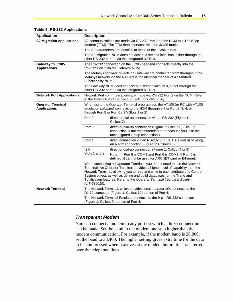
Network Control Module 300 Series Technical Bulletin 15
Table 5: RS-232 Applications Application Description S2 Migration Applications S2 communications are made via RS-232 Port 2 on the NCM to a TableTop
Modem (TTM). The TTM then interfaces with the JC/85 trunk. The S2 parameters are identical to those of the JC/85 trunks. The S2 Migration NCM does not accept a second local bus, either through the other RS-232 port or via the integrated N2 Bus.
Gateway to JC/85 Applications
The RS-232 connection on the JC/85 headend connects directly into the RS-232 Port 2 on the Gateway NCM. The Metasys software objects on Gateway are connected from throughout the Metasys network via the N1 LAN in the identical manner of a Standard Functionality NCM. The Gateway NCM does not accept a second local bus, either through the other RS-232 port or via the integrated N2 Bus.
Network Port Applications Network Port communications are made via RS-232 Port 2 on the NCM. Refer to the Network Port Technical Bulletin (LIT-6295050). When using the Operator Terminal program set, the VT100 (or PC with VT100 emulation software) connects to the NCM through either Port 2, 3, 4, or through Port 5 or Port 6 (ISA Slots 1 or 2). Port 2 direct or dial-up connection via an RS-232 (Figure 1:
Callout 7) Port 3 direct or dial-up connection (Figure 1: Callout 8) (Dial-up
connection is not recommended here because you lose the unconfigured laptop connection.)
Port 4 direct connection via an RS-232 (Figure 1: Callout 9) or using an RJ-12 connection (Figure 1: Callout 10)
ISA Slots 1 and 2
direct or dial-up connection (Figure 1: Callout 4 or 5) Note: Port 5 is COM1 and Port 6 is COM2. If Port 5 is defined, it cannot be used for ARCNET card or Ethernet.
Operator Terminal Applications
When connecting an Operator Terminal, you do not need to use the Network Terminal. An Operator Terminal provides a higher level of capability than the Network Terminal, allowing you to read and write to each attribute of a Control System object, as well as define and build databases for the Trend and Totalization features. Refer to the Operator Terminal Technical Bulletin (LIT-636015).
Network Terminal The Network Terminal, which provides local operator I/O, connects to the RJ-12 connector (Figure 1: Callout 10) portion of Port 4. The Network Terminal Emulator connects to the 9-pin RS-232 connector (Figure 1: Callout 9) portion of Port 4.
Transparent Modem You can connect a modem to any port on which a direct connection can be made. Set the baud to the modem one step higher than the modem communication. For example, if the modem baud is 28,800, set the baud to 38,400. The higher setting gives extra time for the data to be compressed when it arrives at the modem before it is transferred over the telephone lines.

Network Control Module 300 Series Technical Bulletin 16
Battery Pack The battery pack (Figure 1: Callout 11) is secured to a cover and fits over the SIMMs. It automatically recharges from the NCM and maintains the operating system and databases in RAM for up to a 72-hour power failure. Refer to Table 6 for backup times according to memory configuration. You can check on the battery’s status in three ways: a Light-Emitting Diode (LED) indicator, under NCM Diagnostics (NCM Misc Data), or by using WNCSETUP and choosing the Command: Information option (good, bad, not installed).
The NCM arrives from the factory with the battery pack unconnected. Connect the battery last when installing the NCM.
Table 6: Battery Backup Times Memory Configuration Backup Time (Hours) No SIMMs (base memory)* 72 With two 1 MB (3 chip) SIMMs 72 With two 1 MB (9 chip) SIMMs 50 With four 1 MB (3 chip) SIMMs 58 With four 1 MB (9 chip) SIMMs 34 With two 4 MB (3 chip) SIMMs 72 With two 4 MB (9 chip) SIMMs 50 * Standard for the NCM350-8
You must install the battery and power up the NCM for at least 12 hours to ensure the backup times listed in Table 6. As a guideline, if you have an NCM with no additional SIMMs, you get about 10 hours of backup time for each hour of charge time.
Power Up Conditions The Network Control Module powers up in either a cold-start or a warm-start condition. In the cold-start condition, the NCM automatically requests the OWS to download the code and database information into the NCM’s memory. Refer to the Operator Workstation User’s Manual. In a warm-start condition, the code and database are stored in memory, and the NCM is fully operational following the initial diagnostic tests.
By retaining memory during a power cycle, the battery backup provides a warm-start condition when power returns to the NCM. If a Power Fail occurs and the battery is good, a Power Fail message is entered into the NCM error log (NCM3xx and Metasys Release 11.00 or later).

Network Control Module 300 Series Technical Bulletin 17
A System Reload button (Figure 1: Callout 12) resets the NCM, generating a request for a code and data download from the NC archive node address. Table 7 describes power up terminology.
Table 7: NCM300/350 Power Up Terminology Term Description Notes Cold Start Power up restart condition. Runs diagnostics
and clears memory. Downloads code and data files from OWS. Not affected by hardware changes made while power is off.
Start up from no power condition with battery disconnected or dead. Clears all memory, runs diagnostics and reloads all information.
Warm Start Power outage restart. Runs diagnostics but does not clear memory or reload code and data. Resets program counter to program start address after testing unit integrity. It is assumed that no hardware changes are made while the power is off.
Start from power off condition with battery connected and fully charged. Does not clear memory, but does run diagnostics.
Software Reset Already powered up restart. Runs diagnostics but does not clear memory or reload code and data. Resets program counter to program start address after testing unit integrity.
Start from power on condition with battery connected and fully charged. Does not clear memory, but does run diagnostics.
Software Reload Already powered up restart. Runs diagnostics, clears memory, reloads code and data.
Start from power on condition with battery connected and fully charged. Clears all memory, runs diagnostics, and reloads all information.
Reload Button When the Reload button is depressed, the NCM requests a Software Reload. This causes it to restart, run diagnostics, clear the memory, and reload code and data.
Start from power on condition with battery connected and fully charged. Clears all memory, runs diagnostics, and reloads all information.
! IMPORTANT: Install the NU-ROM101 or NU-ROM150 before applying power to the NCM. If either the NU-ROM101 or NU-ROM150 is not installed when power is applied to the NCM, the NCM DRAM and NOVRAM may be corrupted. If the NOVRAM is corrupted, replace the NCM.
Installation Considerations When installing the NCM, note the following:
• Fasten all field ground wires under the top-most screw. This screw contacts the ground plate of the EWC enclosure.
• Connect the battery as the last step in the installation.
• Cycling power before the battery is connected ensures that memory is cleared. Not clearing the memory can cause problems during commissioning, such as rebooting of the NCM.
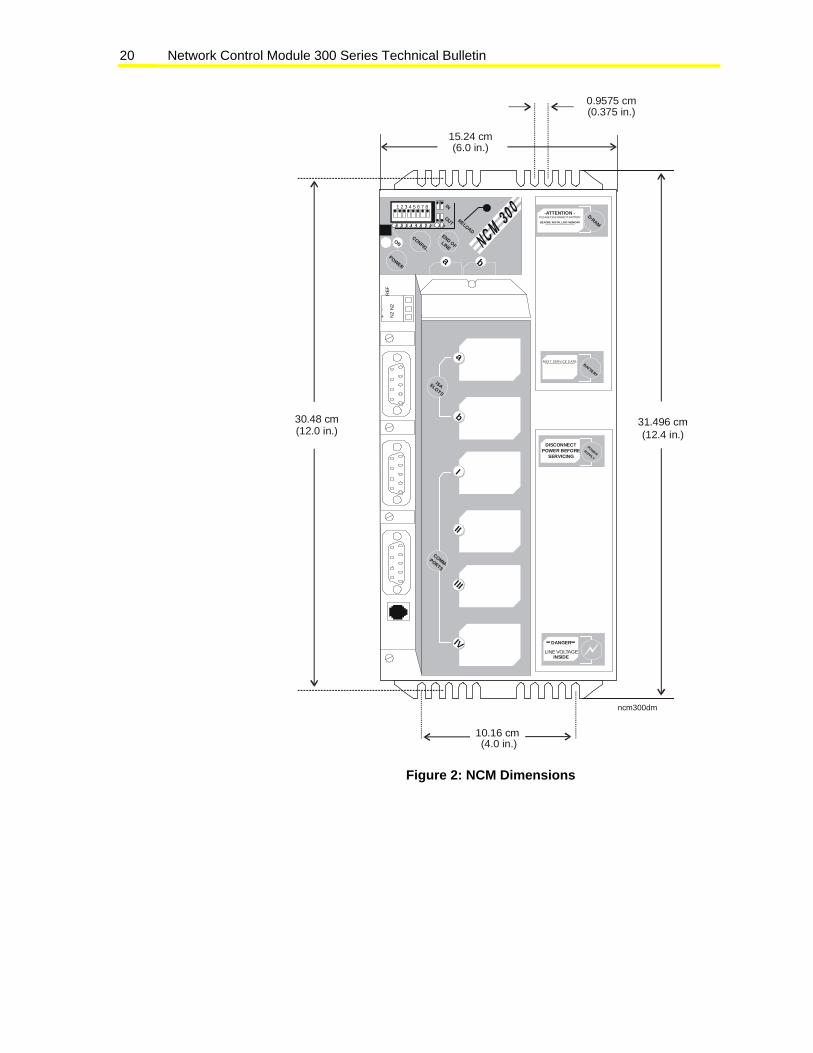
Space and Load-Bearing You must mount the NCM in an enclosure to meet local code requirements. NCM (unmounted) dimensions and weight are: 15 W x 32 H x 14 cm D, 1.7 kg (6 x 12.4 x 5.5 in., 3.8 lb).

Network Control Module 300 Series Technical Bulletin 18
Select a wall space or area with sufficient room to mount the enclosure that contains the NCM. The load-bearing capacity of the wall also must be able to support the unit. Table 8 indicates the dimensions of the Universal Packaging Module (UPM), as well as the fully loaded configuration weight of an NCM with enclosure.
Table 8: UPM Dimensions Enclosure Dimensions EN-EWC22-0 41 W x 41 H x 19 cm D, 5.0 kg (16 x 16 x 7.5 in., 11 lb) EN-EWC35-0 41 W x 59 H x 19 cm D, 7.8 kg (16 x 23 x 7.5 in., 17 lb) EN-EWC45-0 41 W x 77 H x 19 cm D, 9.7 kg (16 x 30 x 7.5 in., 21 lb)
Environment The environment where you mount the NCM must have the following characteristics:
• Ambient temperature limits for the NCM (0 to 50°C, 32 to 122°F) based on convection cooling, as normally installed. Lower temperatures can be accommodated by means of field-installed enclosure heaters. Higher temperatures can be tolerated with some additional forced cooling.
• Ambient humidity must range within 10-90% RH (noncondensing).
• The environment must be free of conductive contaminants such as normal cooking vapors and carbon dust.
IMPORTANT: Do not install the NCM in areas that contain conductive contaminants. Conductive contaminants can result in damage to the NCM.
• Shielded cables are required for RS-232 connections.
• Shielded cables are required for the N1 and N2 networks only when the NCM is mounted in close proximity to radio frequency transmitters (500 to 1000 watts or larger), airport control towers, and hospital nuclear or electronic imaging equipment (for example, operating room, imaging lab).
• The NCM can operate while withstanding vibrations of 5 to 60 Hz of up to 0.5G, and shocks of up to 2G lasting 10 ms. Nonetheless, mount the unit on as stable a surface as possible.

Network Control Module 300 Series Technical Bulletin 19
Power
! IMPORTANT: Install the NU-ROM101 or NU-ROM150 before applying power to the NCM. If either the NU-ROM101 or NU-ROM150 is not installed when power is applied to the NCM, the NCM DRAM and NOVRAM may be corrupted. If the NOVRAM is corrupted, replace the NCM.
Consider the following power requirements for the NCM:
• The NCM requires between 90 and 230 VAC, 500 mA at 50/60 Hz from a single-phase circuit. No switch settings or rewiring are necessary to change from the 120 VAC to 230 VAC.
• Select a power circuit free of heavy equipment loads (for example, large multiphase induction motors).
• The NCM must be referenced (grounded) to a green-wire earth ground.
• Built in AC surge protection circuitry on the NCM is rated to withstand surges of up to 6 kV @ 3 kA (IEEE 587 standard). External surge protection is unnecessary, except in high-voltage environments or in cases of extreme lightning.
• Do not use a Spade Bit to make a hole in the EWC for the power conduit, or the NCM’s grounding strip will be damaged. Use a Step-Bit or Greenlee Tool to make a hole for the conduit.
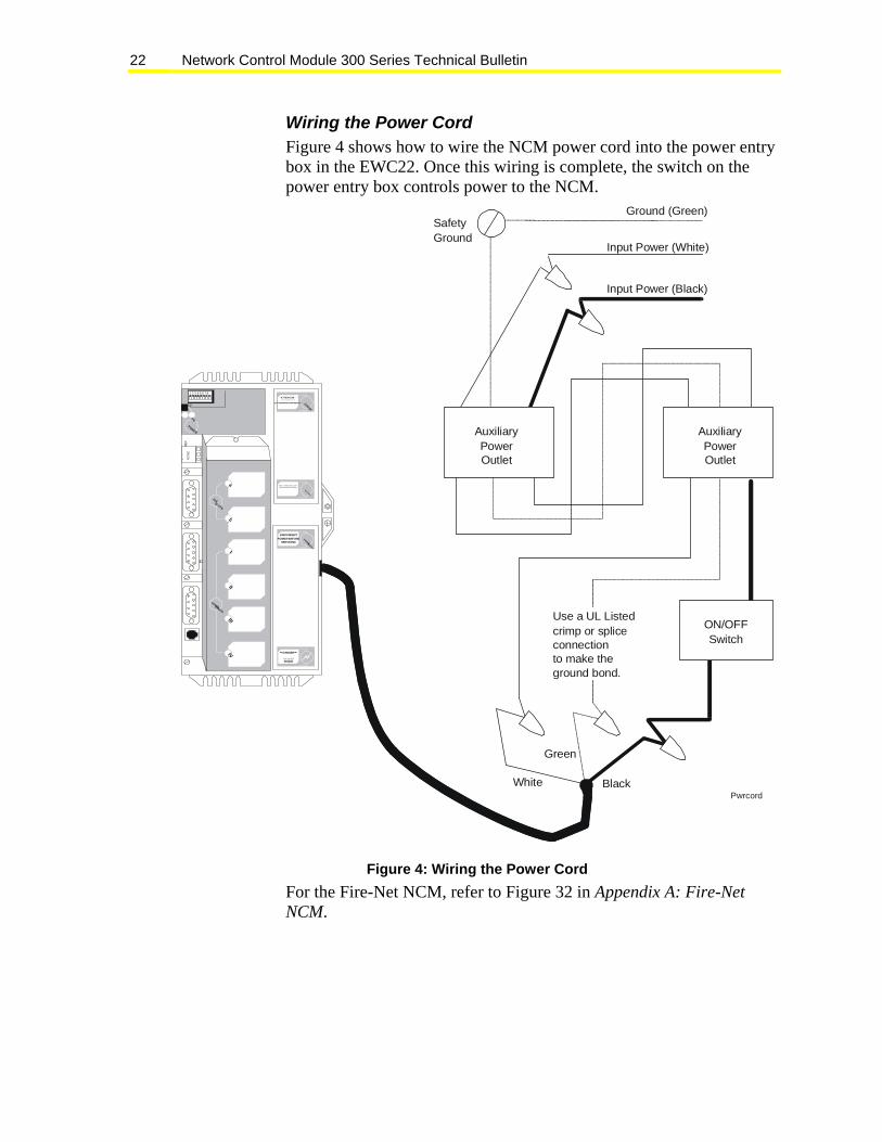
• Figure 4 shows how to wire the NCM power cord into the power entry box in the EWC22. Once this wiring is complete, the switch on the power entry box controls power to the NCM.
• Figure 5 shows how to wire the power connection into the NCM311 or NCM361.
Design Considerations Mounting Mount the NCM in a suitable enclosure near its line voltage connections. The unit is designed to fit into a variety of enclosures. Figure 2 shows the overall mounting dimensions. Figure 3 shows the NCM mounted in an EWC22. Figure 4 shows how to wire the NCM power cord into the power entry box in the EWC22. For more information on the EWC22, see the Universal Packaging Module Technical Bulletin (LIT-6363070).
Network Control Module 300 Series Technical Bulletin 20
ncm300dm
1 2 3 4 5 6 7 8
1 2 3 4 5 6 7 8
IN
OUT RELOAD
POWER
ONCONFIG.
END OFLINE
a b
D-RAM
-ATTENTION -PLEASE DISCONNEDT BATTERY
BEFORE INSTALLING MEMORY
BATTERY
N EXT SERVICE D ATE:
REF
N2
-
N2
+
a
b
ISASLOTS
I
II
IV
COMM-PORTS
III
POWERSUPPLY
DISCONNECTPOWER BEFORE
SERVICING
DANGER
LINE VOLTAGEINSIDE
31.496 cm30.48 cm
10.16 cm
15.24 cm(6.0 in.)
(0.375 in.)0.9575 cm
(12.4 in.)
(4.0 in.)
(12.0 in.)
Figure 2: NCM Dimensions

Network Control Module 300 Series Technical Bulletin 21
REF
N2
-
N2
+
nc3upm
Figure 3: NCM Mounted into an EN-EWC22-0
Network Control Module 300 Series Technical Bulletin 22
Wiring the Power Cord Figure 4 shows how to wire the NCM power cord into the power entry box in the EWC22. Once this wiring is complete, the switch on the power entry box controls power to the NCM.
1 2 3 4 5 6 7 8
1
2 3 4 5 6 7 8
IN
OUTRELOAD
7 8
POWER
ON
CONFIG.
END OFLINEa b
D-RAM
-ATTENTION -P LE A SE D IS C ON N ED T BA TT E RY
B EFO R E IN S TA LLI N G ME MO R Y
BA TTE RY
N EX T S ER VI CE D ATE :
RE
FN
2
-
N2
+
a
b
ISASLOTS
I
II
IV
COMM-PORTS
III
POWERSUPPLY
DISCONNECTPOWER BEFORE
SERVICING
DANGER
LI NE VOLTAGE
INSIDE
Ground (Green)SafetyGround
Input Power (White)
Input Power (Black)
ON/OFFSwitch
Black
Green
White
AuxiliaryPowerOutlet
AuxiliaryPowerOutlet
Use a UL Listedcrimp or spliceconnectionto make theground bond.
Pwrcord
Figure 4: Wiring the Power Cord For the Fire-Net NCM, refer to Figure 32 in Appendix A: Fire-Net NCM.

Network Control Module 300 Series Technical Bulletin 23
Figure 5 shows how to wire the power connection into the NCM311 and NCM361.
1 2 3 4 5 6 7 8
1 2 3 4 5 6 7 8
IN
OUT RELOAD7 8
POWER
ONCONFIG.
END OFLINE
a b
RE
FN
2+N
2-
a
b
ISASLOTS
I
II
IV
COMM-PORTS
III
POWER
SUPPLY
DISCONNECTPOWER BEFORE
SERVICING
DANGER
LINE VOLTAGE
INS IDE
D-RAM
-ATTENTION -PLE AS E DI SC ON N ED T BATT ER Y
BEFORE INSTALLING MEMO RY
BATTERY
NEXT SERVICE DATE:
Line (brown)
Neutral (blue)
Ground (green/yellow)
Gray
Green/Yellow
Ground (green/yellow)
Neutral(blue)
Line(brown)
ON/OFFSwitch
CORD-311
Figure 5: Wiring to Power Terminals of the NCM311 and NCM361

Network Control Module 300 Series Technical Bulletin 24
Replacing an NCM401 with an NCM300 Because Port 1 of the NCM300 is always the built-in N2, you must move the S2 trunk from Port 1 on an NCM401 to Port 2 on the NCM300.
For applications combining dial-up and S2, the NCM350 running Metasys Release 8.0 or later software supports modems on Port 5 or 6. Internal modems are not recommended. See the ISA Bus Cards section of this document. See Replacing an NCM401 with an NCM300 in Detailed Procedures for replacement steps.
Software Configurations The NCM300 requires Release 6.0 or later of Metasys software. The NCM350 requires Release 8.0 or later of Metasys software. The NCM350-8 requires Release 9.01 or later of Metasys software to get the full use of the 8 MB of memory. Metasys software Release 8.0 through Release 9.0 only recognize an NCM350-8 as having 6 MB of memory because there was no 8 MB option at those releases.
The NCM Software Options Technical Bulletin (LIT-636023) indicates the software configurations that can be downloaded into each NCM base hardware option, and which Metasys hardware devices can be connected to the specific NCM configurations.
For information on the Fire-Net NCM, refer to Appendix A: Fire-Net NCM in this document.
NCM Capacity The allocated memory is the database memory. The acquired memory is temporary memory. Table 9 shows the amounts of allocated and acquired memory are available on the NCM, according to the four levels of available DRAM. Table 10 describes NCM functionality.
Table 9: NCM Memory Capacity DRAM Size Allocated
(Database Memory) Acquired (Temporary Memory)
2 MB 580 KB 150 KB 4 MB 2 MB 300 KB 6 MB 4 MB 300 KB 8 MB 6 MB 300 KB 10 MB 8 MB 300 KB Note: Only the 8 MB option applies to NCM350-8.
Network Control Module 300 Series Technical Bulletin 25
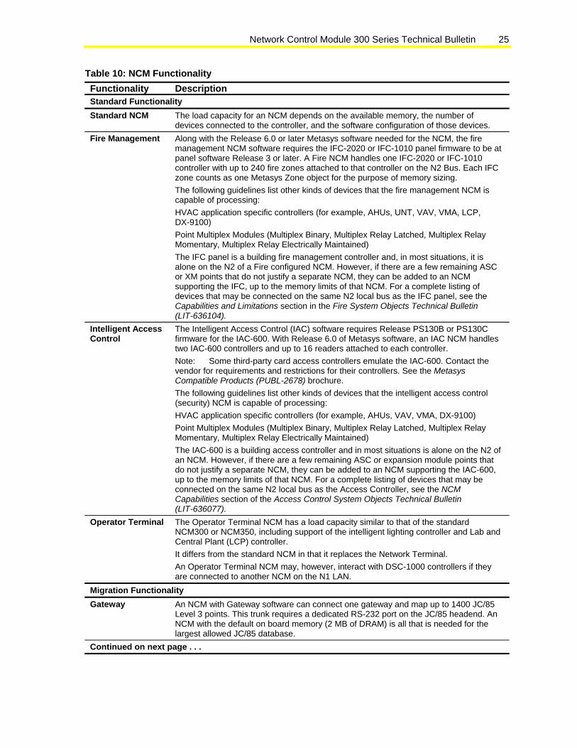
Table 10: NCM Functionality Functionality Description Standard Functionality Standard NCM The load capacity for an NCM depends on the available memory, the number of
devices connected to the controller, and the software configuration of those devices. Fire Management Along with the Release 6.0 or later Metasys software needed for the NCM, the fire
management NCM software requires the IFC-2020 or IFC-1010 panel firmware to be at panel software Release 3 or later. A Fire NCM handles one IFC-2020 or IFC-1010 controller with up to 240 fire zones attached to that controller on the N2 Bus. Each IFC zone counts as one Metasys Zone object for the purpose of memory sizing. The following guidelines list other kinds of devices that the fire management NCM is capable of processing: HVAC application specific controllers (for example, AHUs, UNT, VAV, VMA, LCP, DX-9100) Point Multiplex Modules (Multiplex Binary, Multiplex Relay Latched, Multiplex Relay Momentary, Multiplex Relay Electrically Maintained) The IFC panel is a building fire management controller and, in most situations, it is alone on the N2 of a Fire configured NCM. However, if there are a few remaining ASC or XM points that do not justify a separate NCM, they can be added to an NCM supporting the IFC, up to the memory limits of that NCM. For a complete listing of devices that may be connected on the same N2 local bus as the IFC panel, see the Capabilities and Limitations section in the Fire System Objects Technical Bulletin (LIT-636104).
Intelligent Access Control
The Intelligent Access Control (IAC) software requires Release PS130B or PS130C firmware for the IAC-600. With Release 6.0 of Metasys software, an IAC NCM handles two IAC-600 controllers and up to 16 readers attached to each controller. Note: Some third-party card access controllers emulate the IAC-600. Contact the vendor for requirements and restrictions for their controllers. See the Metasys Compatible Products (PUBL-2678) brochure. The following guidelines list other kinds of devices that the intelligent access control (security) NCM is capable of processing: HVAC application specific controllers (for example, AHUs, VAV, VMA, DX-9100) Point Multiplex Modules (Multiplex Binary, Multiplex Relay Latched, Multiplex Relay Momentary, Multiplex Relay Electrically Maintained) The IAC-600 is a building access controller and in most situations is alone on the N2 of an NCM. However, if there are a few remaining ASC or expansion module points that do not justify a separate NCM, they can be added to an NCM supporting the IAC-600, up to the memory limits of that NCM. For a complete listing of devices that may be connected on the same N2 local bus as the Access Controller, see the NCM Capabilities section of the Access Control System Objects Technical Bulletin (LIT-636077).
Operator Terminal The Operator Terminal NCM has a load capacity similar to that of the standard NCM300 or NCM350, including support of the intelligent lighting controller and Lab and Central Plant (LCP) controller. It differs from the standard NCM in that it replaces the Network Terminal. An Operator Terminal NCM may, however, interact with DSC-1000 controllers if they are connected to another NCM on the N1 LAN.
Migration Functionality Gateway An NCM with Gateway software can connect one gateway and map up to 1400 JC/85
Level 3 points. This trunk requires a dedicated RS-232 port on the JC/85 headend. An NCM with the default on board memory (2 MB of DRAM) is all that is needed for the largest allowed JC/85 database.
Continued on next page . . .

Network Control Module 300 Series Technical Bulletin 26
Functionality (Cont.)
Description
Network Port Application
See the Network Port Technical Bulletin (LIT-6295050).
S2 Migration An NCM with S2 software can connect one JC/85 trunk through one TableTop Modem (for example, if four trunks originally connected to the JC/85 headend, four NCMs are required unless the trunks can be reconfigured). The database size of each trunk determines how much DRAM is required. An NCM with 2 MB of DRAM typically processes 250-350 objects. Estimating considerations follow. Countable JC/85 objects: FPU device FPU hardware points (the SST101 counts as two objects) DSC-8500 device DSC-8500 hardware points DSC-8500 data points DSC-8500 status variables In addition to the memory required by the object count and Metasys software standard features, also calculate additional memory used for written programs of Graphic Programming Language (GPL) equivalents to JC/85 features. See How to Use the Metasys GPL HVAC Library Technical Bulletin (LIT-636121). Applications of interest to JC/85 users are: interlocks computed points chiller sequencing Among the considerations about adapting JC/85 code to the Metasys system, here are two that may adjust the memory requirements: Auto Shutdown When converting the JC/85 Auto Shutdown feature, write an equivalent GPL process for the Metasys system and add the file object size to the NCM’s memory usage. ESO (Enthalpy Switch Over) When converting the JC/85 ESO feature, you must choose one of the four economizer features utilized in the Metasys system. ECONEN Comparison Enthalpy Economizer ECONOE Outdoor Air Enthalpy Economizer ECONDB Outdoor Air Dry Bulb Economizer ECONRA Differential Temperature Economizer Details and specifications about each of these programs are listed in How to Use the Metasys GPL HVAC Library (LIT-636121).
Port Configurations: Standard Functionality Table 11 shows applications and port restrictions when downloading one of the Standard Functionality software sets (Standard, Fire Management, Intelligent Access Control, Operator Terminal). Table 12 shows device restrictions for each port.

Network Control Module 300 Series Technical Bulletin 27
Table 11: Standard Functionality Serial Port Configurations Connection Maximum
Concurrent Connections5
Port 1 (RS-485)
Port 2 (Dial)6,
9
Port 3 (Laptop)2
Port 4 (NT)11, 12
Port 5 (ISA 1) (COM1)
Port 6 (ISA 2) (COM2)
N2 2 L21 1 S21 1 JC/85 Gateway 1 Network Port 1 OWS-Direct (Configured8)
2 ,3 ,3
OWS-Dial7 1 ,3 ,3 ,3 OWS (Unconfigured10)
1 ,15 ,15
NT 1 NT-Emulator 1 OT4,16 1 OT-Dial4, 7,16 1 NC Printer 2 NC Printer-Dial7 1 N1 – ARCNET Ethernet LONWORKS 1 Media Interface Board14
Maximum Speed -- 19.2 K 19.2 K 19.2 K 19.2 K 57.6 K13 57.6 K13
1. The L2 and S2 Bus connections require additional hardware. 2. Direct connection is recommended on Port 3 for the OWS. This allows connection to systems locally. 3. Download from remote OWS is only available on the NCM350/361. 4. Use of the Operator Terminal (OT) replaces the Network Terminal and disables the NT port. 5. The maximum number of connections of that type on the NCM. For example, there can be two N2
connections on the NCM, on Ports 1 and/or 2 and one OWS dial connection on the NCM, on Port 2, 3, 5, or 6.
6. All devices connect to the integrated RS-232 port via RS-232 cable. Connections at the integrated ports are independent of each other; for example, a printer can be connected to both ports at the same time.
7. Dial-up printer, OWS, or OT connected to phone line via a modem. 8. A configured OWS is an OWS that is defined in the database. 9. N2 Bus can connect to this port via an RS-232 to RS-485 converter. 10. An unconfigured OWS is not defined in the database (for example, a laptop computer). Use it to run logs
and summaries, or to download a database. They cannot be connected directly to the Ethernet LAN. 11. Either an NT or an OT directly connects to the RJ-12 port via the NT Emulator cable. 12. Either an OT or a PC with NT Emulator software directly connects to the RS-232 port via RS-232 cable. 13. For modem connection, the baud can be 33.6 K (however, the baud should be set to 38.4). For direct
connect and ISDN, the maximum baud is 57.6 K. LONWORKS bus communicates at 78 K baud. Ethernet communicates at 10 megabits per second (Mbps). ARCNET communicates at 2.5 Mbps.
14. Only use Media Interface Board (MIB-OWS) on the Fire-Net NCM (NU-NCM300-FIRE or NU-NCMFIRE-1).15. You can connect an unconfigured OWS to Ports 5 and 6 if there is a configured device defined on the port. 16. You cannot have both a direct and a dial OT on the same NCM.

Network Control Module 300 Series Technical Bulletin 28
Table 12: Port Restrictions Port Application
(Ports must be configured via system software for appropriate application.)N2 (Port 1) N2 Bus (RS-485) Connections Integrated RS-232 Port (Port 2)
All devices connect to the integrated RS-232 port via RS-232 cable. Connections at the integrated ports are independent of each other; for example, it is possible to have a printer connected to both ports at the same time.
Local Printer Dial-Up Printer, OWS, or Operator Terminal, connected to phone line via an external
modem. (Dial-Up Operator Terminal disables the NT Port.) Configured OWS (defined in the database) Operator Terminal (disables NT Port) N2 Bus can connect to this port via an RS-232 to RS-485 converter. Integrated RS-232 Port (Port 3)
Configured OWS or Direct or Dial-up* (defined in the database)
Printer, Direct or Dial-up* Unconfigured OWS (not defined in the database): An example is a laptop computer used
to run logs and summaries, or to download a database. Direct or Dial-up OT NT Port (Port 4) Network Terminal directly connects to the RJ-12 port via the NT cable
Or Operator Terminal directly connects to the RJ-12 port via the NT Emulator cable.
Operator Terminal directly connects to the RS-232 port via RS-232 cable. Or PC Running NT Emulator software directly connects to the RS-232 port via RS-232 cable.(Operator terminal not used during Network Terminal applications.)
ISA Slots Configured OWS, Direct or Dial-up (defined in the database) Printer, Direct or Dial-up Direct or Dial-Up OT LONWORKS devices (Port 6 only) connected using LONWORKS network connected to the
LONWORKS interface card in Slot 2. MIB-OWS must be placed in Slot 2 (Port 6) NU-NCM300-FIRE only. N1 LAN (either Ethernet or ARCNET may be used, but not both.) * Defining a dial-up OWS/printer prevents a direct connection to either a configured or an unconfigured OWS/printer.

Network Control Module 300 Series Technical Bulletin 29
Port Configurations: Migration Functionality Table 13 illustrates applications and port restrictions when downloading one of the Migration Functionality software sets; for the Network Port application, see the Network Port Technical Bulletin (LIT-6295050).
Table 13: Migration Functionality Serial Port Configurations Port Application
(Ports must be configured via system software for appropriate application.)
N2 (Port 1) N2 Bus (RS-485) connections Integrated RS-232 Port (Port 2)
All devices connect to the integrated RS-232 port via RS-232 cable.
S2 Migration, connected via RS-232 to JC/85 trunk via TableTop Modem. JC/85 Gateway, connected via RS-232 to JC/85 headend. (Connection may
alternately be via a high-speed modem over a dedicated phone line.) Integrated RS-232 Port (Port 3)
Configured OWS (defined in the database)
Printer Unconfigured OWS (not defined in the database): An example is a laptop computer
used to run logs and summaries, or to download a database. NT Port (Port 4) Network Terminal directly connects to the RJ-12 port via the NT cable. ISA Slots Configured OWS, Direct or Dial-up (defined in the database) Printer, Direct or Dial-up Direct or Dial-Up OT LONWORKS devices (Slot B only) connected using LONWORKS network connected to
the LONWORKS interface card. MIB-OWS must be placed in Slot B, NU-NCM300-FIRE/NU-NCMFIRE-1 only. N1 LAN (must be placed in Slot A, either Ethernet or ARCNET may be used, but
not both.) Notes: JC/85 Gateway: To send the NCM print file to the JC/85 printer, define the printer as Port 2, the same port definition assigned to Gateway. To print to a printer connected directly to the NCM, connect the printer into an available port, such as Port 3 integrated RS-232 port. Operator Terminal: To send a Change-of-State (COS) to the Operator Terminal, a printer must be defined on Port 0. (Prior to Release 8.0, Port 3 was used for this purpose.)
NCM Cable Guidelines This section describes and illustrates the network connections.
This section also describes and illustrates cable connections to Ports 2, 3, and 4 by device (such as by OWS, printer), and by migration type (Gateway or S2).
N2 Bus (Port 1) This three-wire termination accepts RS-485 signals via the N2 Bus (see Figure 6). For further details about making N2 Bus connections, refer to the N2 Communications Bus Technical Bulletin (LIT-636018). To add a second N2, make connections to Port 2 of the NCM using a MM-CVT101 (RS-485 to RS-232 converter).

Network Control Module 300 Series Technical Bulletin 30
12
3
4
5
6
7
8
9
DCD
RXD
TXD
DTR
GND
DSR
RTS
CTS
NC
NCM300
9-pin Female
1
2
3
4
5
6
7
8
9
CVT10125-pin Male
NCM300Port 1 - N2 Bus
RE
F N2- N
2+
nc3fig5
Port 2
Figure 6: N2 Bus Connections
NCM N1 LAN Connection The instructions provided here are for ARCNET. If you are using Ethernet, refer to Setting Up the Metasys Network on Ethernet in the N1 Ethernet/IP Network Technical Bulletin (LIT-6360175).
The standard ISA connection (Slot 1) can accept an ARCNET card to transmit and receive N1 LAN communications. When one of the slots is occupied by an ARCNET card, the remaining slot can contain a serial card; however, another standard ARCNET card or Ethernet card is not allowed.
Johnson Controls stocks an ARCNET card (NU-NET101-0). See the Operator Workstation Technical Bulletin (LIT-636013) for information on other supported cards.
Table 14 shows the configuration values for the ARCNET card.
Table 14: ARCNET Card Configuration Values Configuration Value I/O Base Address 300H Memory Base Address C0000H Interrupt (IRQ) IRQ 4 Bus or Star Configuration This depends on your application, typically a bus configuration.
Enhanced/Compatible Mode Compatible
Notes: The Bus or Star Configuration and Enhanced/Compatible mode values are not used with the CCSI ARCNET PCA66-CXB adapter card. Make sure the compatible mode is selected and that all other configuration values are correct, or the board does not work. Consult the configuration guide supplied with the board for detailed instructions on how to set these values.

Network Control Module 300 Series Technical Bulletin 31
Figure 7 shows how to make the N1 connection on the ARCNET card. In the Troubleshooting Procedures section of this document, Related Commissioning Problems lists some N1 End-of-Line (EOL) termination notes regarding N1 cabling and termination.
Note: Make sure metallic portions of N1 Network connectors are not contacting ground. Wrap them with insulating tape if contact is possible.
ncm3005
1 2 3 4 5 6 7 8
1 2 3 4 5 6 7 8
IN
OUT7 8
POWER
ONCONFIG.
END OFLINE
REF
N2-N
2+
a b
RELOAD
POWERSUPPLY
DISCONNECTPOWER BEFORE
SERVICING
DANGER
LINE VOLTAGE
INSIDE
D-RAM
-ATTENTION -PLEASE DISCONNEDT BATTERY
BEFORE INSTALLING MEMORY
IV
III
II
I
Tee
EOL Termination (93 ohm)
BATT ERY
NEXT SERVICE DATE:a
b
ISASLOTS
I
II
IV
COMM-PORTS
III
Figure 7: N1 LAN Connection
LONWORKS Connection A LONWORKS ISA card (NU-NET201-0, NU-NET202-0, NU-NET203-0, or NU-NET203-1) is required in an NCM in order to connect it to a LONWORKS network. Install the card into ISA Slot 2 of the NCM. An end-of-line termination must be installed at each end of the bus to balance the LONWORKS communications signal.
Refer to detailed instructions in the LONWORKS N2E Bus Technical Bulletin (LIT-6364100) or the LONWORKS Network Layout Technical Bulletin (LIT-1162150).

Network Control Module 300 Series Technical Bulletin 32
RS-232 Ports (2 and 3) The RS-232C ports provide input/output at standard RS-232C levels using the DTE protocol.
The user connects a cable with a DB9 Female connector onto the NCM (detailed pinouts follow for each device).
All RS-232 connections to third-party equipment must be made with shielded cable.
As a condition for meeting European Emissions requirements, and being able to apply the CE Mark, we are required to use a ferrite clamp (supplied with every NCM311) if an RS232 cable is used on Serial Port 2. Figure 8 shows how to attach the ferrite clamp.
Mount the ferrite clamp on the serial cable as closely as possible to the 9-pin IBM® serial port connector. It can be held in place by a cable tie mounted directly behind the ferrite clamp.

Network Control Module 300 Series Technical Bulletin 33
RE
FN
2-N
2+
1 2 3 4 5 6 7 8
1 2 3 4 5 6 7 8
IN
OUT7 8
POWER
ONC ONF IG.
END OFLINE
a b
RELOAD
POWERSUPPLY
DIS CONNECTPO WER BEFO RE
SE RV ICING
DANG ER
LINE VOLTAGE
INSIDE
D-RAM
-ATTENTIO N -PLEASE DISCONNEDT BATTERY
BEFORE INSTALLING MEMORY
IV
III
I
BATTERY
NEXT SERVICE DATE:a
b
ISASLOTS
I
II
IV
COMM-PORTS
III
Cable Tie
FerriteClamp
IBM Serial Port9-pin Female
Connector
clamp
Figure 8: Attaching the Ferrite Clamp on the NCM311 or NCM361

Network Control Module 300 Series Technical Bulletin 34
Standard Cables Table 15 provides an overview of cables used with the NCM.
Table 15: Standard Cables Description of Connectors (Gender and Pin No.)
Commonly Used Names
NCM Device
Applies to Figures
IBM AT to Null Modem (DTE-DTE)
Female DB9 Female DB9 9, 10, 16, 18
IBM AT to Modem (Straight-through) (DTE-DCE)
Female DB9 Male DB25 6, 11, 15, 21
IBM AT to Printer (DTE-DCE)
Female DB9 Male DB25 12
IBM AT to Null Modem (DTE-DTE)
Female DB9 Male DB25 w/ gender changer (Female to Female)
9, 17, 18
Notes: Figure 13, Figure 18, and Figure 19 are special cases requiring custom cables. The NCM, Companion, and DX9100 RS232 ports have identical pinouts. Standard null modem cables do not normally have a jumper from DCD to DSR. At Metasys Release 8.0 and later, this jumper is required for proper operation.
OWS Cabling Figure 9 illustrates the NCM connections to either the 25-pin or 9-pin OWS.
1
2
3
4
5
6
7
8
9
DCD
RD
TD
DTR
SG
DSR
RTS
CTS
NC
NCM9-pin Female
1
2
3
4
5
6
7
8
20
PC Serial Port25-pin Female
1
2
3
4
5
6
7
8
9
DCD
RD
TD
DTR
SG
DSR
RTS
CTS
NC
NCM9-pin Female
1
2
3
4
5
6
7
8
9
PC Serial Port9-pin Female
nc3fig7
Shell Shell Shell
DCD
RD
TD
DTR
SG
DSR
RTS
CTS
FG
TD
RD
RTS
CTS
DSR
SG
DCD
DTR
Figure 9: PC Serial Port of OWS Connected
Network Control Module 300 Series Technical Bulletin 35
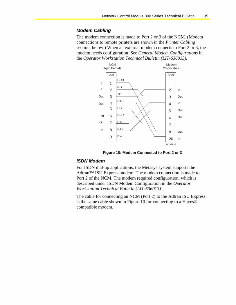
Modem Cabling The modem connection is made to Port 2 or 3 of the NCM. (Modem connections to remote printers are shown in the Printer Cabling section, below.) When an external modem connects to Port 2 or 3, the modem needs configuration. See General Modem Configurations in the Operator Workstation Technical Bulletin (LIT-636013).
1
2
3
45
6
7
8
9
DCD
RD
TD
DTR
SG
DSR
RTS
CTS
NC
NCM9-pin Female
2
3
4
5
6
7
8
20
Modem
Shell
NC3FIG9
Shell
In
In
Out
Out
In
Out
In
In
Out
In
Out
Out
Out
In
25-pin Male
Figure 10: Modem Connected to Port 2 or 3
ISDN Modem For ISDN dial-up applications, the Metasys system supports the Adtran™ ISU Express modem. The modem connection is made to Port 2 of the NCM. The modem required configuration, which is described under ISDN Modem Configuration in the Operator Workstation Technical Bulletin (LIT-636013).
The cable for connecting an NCM (Port 2) to the Adtran ISU Express is the same cable shown in Figure 10 for connecting to a Hayes® compatible modem.

Network Control Module 300 Series Technical Bulletin 36
Printer Cabling Printers are not a component of the NCM. However, acceptable printers are those you can configure to a Lexmark® Proprinter® emulation mode and have either an available serial connection option or the ability to connect to the NCM through an RS-232 serial to a parallel converter.
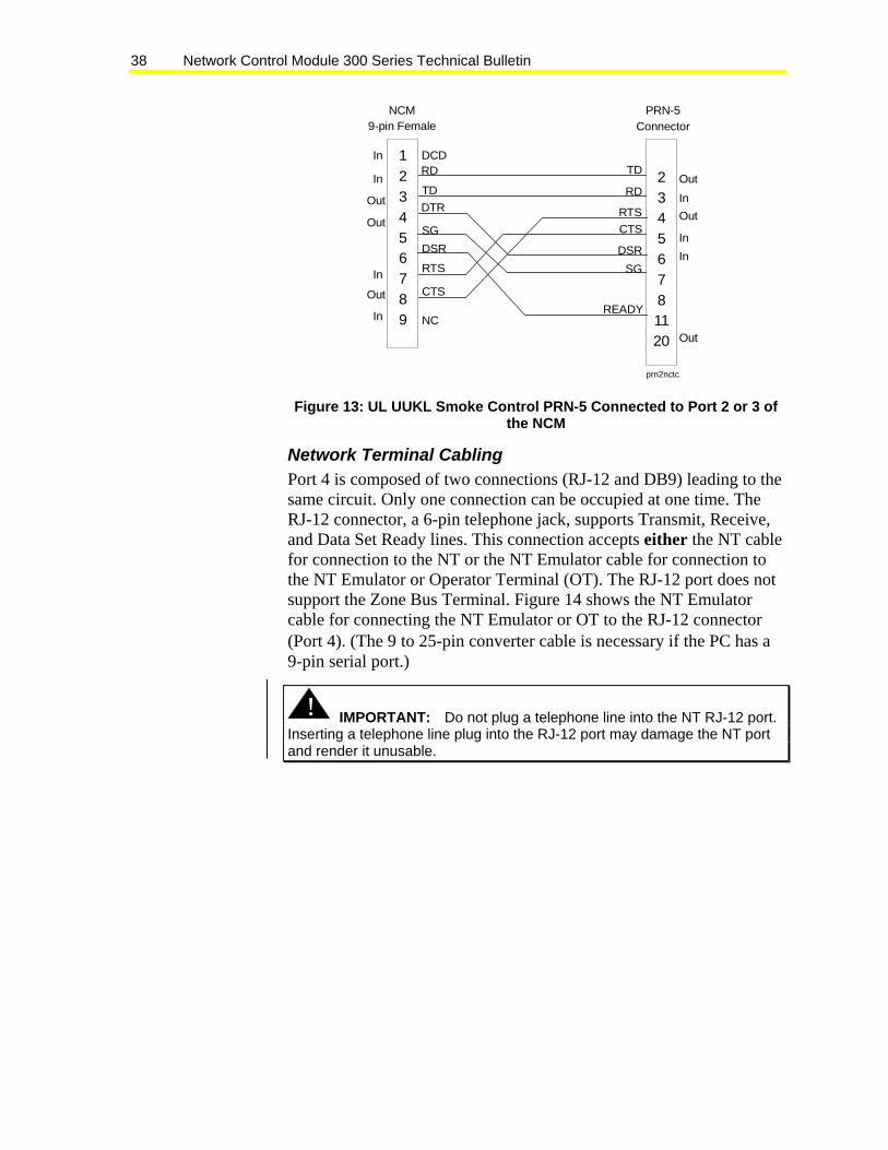
Notes: Smoke control applications require a printer connection to the NCM. In this case, use the same Mannesmann Tally PRN-5 that connects to the IFC. Switch settings are described below; Figure 13 shows the pinout connections to either Port 2 or Port 3. For the smoke control application, the baud must be 1200 or lower. (A higher baud may cause the printer to go offline if the printer buffer overflows.)
If you are using the Color Printing feature for printing alarms, do not connect the color printer to the NCM. The printer must be connected to the OWS for color printing to work. Refer to the Operator Workstation Technical Bulletin (LIT-636013) for details.
The following printer cable diagrams are typical but may not be exact for your interface.
To properly configure the printer for the NCM, use the individual printer instructions as a guide to set the mode and DIP switches to the configurations shown in Table 16.
Table 16: DIP Switch Configuration Configuration Value Card Serial Interface Mode RS-232 Polarity No reverse polarity (Typically this setting could change,
depending on the individual computer system and cabling.) Baud Set to the rate established in DDL. The default is 9600. For
smoke control applications using the Mannesmann Tally PRN-5, the baud must be 1200.
Data Bits 8 Parity No Stop Bits 1 Protocol XON/XOFF Operation Normal

Network Control Module 300 Series Technical Bulletin 37
A Lexmark Proprinter III printer connects to either Port 2 or 3 of the NCM, or to a remote Hayes compatible modem. Figure 11 shows the printer connections to Ports 2 and 3; Figure 12 shows connections to the modem. Cable connections for the Lexmark Model 2380 (using Proprinter emulation) are the same as shown for the Lexmark Proprinter III. Figure 13 shows the Mannesmann Tally PRN-5 connections to the NCM for UL UUKL Smoke Control applications.
1
2
3
4
5
6
7
8
9
DCD
RD
TD
DTR
SG
DSR
RTS
CTS
NC
2
3
4
5
6
7
8
20
IBM Proprinter III25-pin Male
NCM9-pin Female
Shell Shell
nc3fig10
Out
In
Out
In
Out
In
Out
In
In
SG
Out
Out
In
Figure 11: Lexmark Proprinter III Connected to NCM Port 2 or 3 In Proprinter III dial-up applications, refer to Figure 10 for the pin connections from the NCM to the local modem. Figure 12 shows the connections between the remote modem and Lexmark Proprinter III.
Out
Out
Out
Out
Out
Out
Out
In
In
In
In
In
In
In
FG123456781820
Shell
2345678
1820
IBM Proprinter III(Male; NU-CBL101-0)
Modem(Male; MHK101)
Black
Brown
Red
Orange
Yellow
Green
Blue
Violet
White
200tc15
Figure 12: Lexmark Proprinter III Connected to Modem
Network Control Module 300 Series Technical Bulletin 38
DCD123456789
23456781120
NCM9-pin Female
PRN-5Connector
RD
NC
prn2nctc
In
In
In
In
Out
Out
Out
InOut
Out
Out
InIn
TD
TD RDDTR
DSR
SG
SG
DSR
READY
CTS
RTS
CTS
RTS
Figure 13: UL UUKL Smoke Control PRN-5 Connected to Port 2 or 3 of the NCM
Network Terminal Cabling Port 4 is composed of two connections (RJ-12 and DB9) leading to the same circuit. Only one connection can be occupied at one time. The RJ-12 connector, a 6-pin telephone jack, supports Transmit, Receive, and Data Set Ready lines. This connection accepts either the NT cable for connection to the NT or the NT Emulator cable for connection to the NT Emulator or Operator Terminal (OT). The RJ-12 port does not support the Zone Bus Terminal. Figure 14 shows the NT Emulator cable for connecting the NT Emulator or OT to the RJ-12 connector (Port 4). (The 9 to 25-pin converter cable is necessary if the PC has a 9-pin serial port.)
! IMPORTANT: Do not plug a telephone line into the NT RJ-12 port. Inserting a telephone line plug into the RJ-12 port may damage the NT port and render it unusable.

Network Control Module 300 Series Technical Bulletin 39
+5V
NCM300RJ-12
OT or PC25-pin Female
FGDSR
TD
RD
SG
DTR
TD
RD
RTS
CTS
DSR
DCD
SG
2345678
20
25-pinMale
2345678
ntemucab
PC9-pin Female
Shell Shell
NT Emulator Cable 9 to 25-pin Converter Cable
DCD
RD
TD
DTRSG
DSR
CTS
RTS
1234567
8
20
123456
Figure 14: NT Emulator Cable for Connecting NT Emulator or OT to RJ-12 Connector (Port 4) Figure 15 shows the alternative cable you can use if either your RJ-12 connector or NT Emulator cable is damaged. This cable connects the NT Emulator to the DB9 connector (Port 4).
1
2
3
4
5
6
7
8
9
DCD
RXD
TXD
DTR
GND
DSR
RTS
CTS
NC
NCM9-pin Female
2
3
4
5
6
7
8
20
IBM Serial Port25-pin Female
1
2
3
4
5
6
7
8
9
DCD
RXD
TXD
DTR
GND
DSR
RTS
CTS
NC
NCM9-pin Female
1
2
3
4
5
6
7
8
9
IBM Serial Port9-pin Female
nc3ntemu
Figure 15: Cable for Connecting NT Emulator to DB9 Connector (Port 4)
Network Control Module 300 Series Technical Bulletin 40
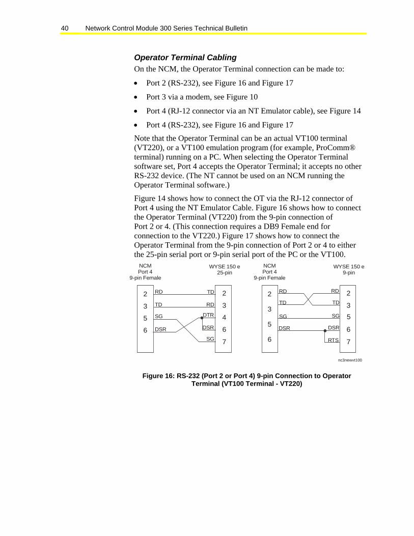
Operator Terminal Cabling On the NCM, the Operator Terminal connection can be made to:
• Port 2 (RS-232), see Figure 16 and Figure 17
• Port 3 via a modem, see Figure 10
• Port 4 (RJ-12 connector via an NT Emulator cable), see Figure 14
• Port 4 (RS-232), see Figure 16 and Figure 17
Note that the Operator Terminal can be an actual VT100 terminal (VT220), or a VT100 emulation program (for example, ProComm® terminal) running on a PC. When selecting the Operator Terminal software set, Port 4 accepts the Operator Terminal; it accepts no other RS-232 device. (The NT cannot be used on an NCM running the Operator Terminal software.)
Figure 14 shows how to connect the OT via the RJ-12 connector of Port 4 using the NT Emulator Cable. Figure 16 shows how to connect the Operator Terminal (VT220) from the 9-pin connection of Port 2 or 4. (This connection requires a DB9 Female end for connection to the VT220.) Figure 17 shows how to connect the Operator Terminal from the 9-pin connection of Port 2 or 4 to either the 25-pin serial port or 9-pin serial port of the PC or the VT100.
NCMPort 4
9-pin Female
WYSE 150 e25-pin
2
3
5
6
2
3
7
4
6
NCMPort 4
9-pin Female
WYSE 150 e9-pin
2
3
5
6
2
3
7
6
5
RD
TD
SG
DSR
RD
TD
SG
DSR
DTR
RD
TD
SG
DSR
RD
TD
SG
DSR
RTS
nc3newvt100
Figure 16: RS-232 (Port 2 or Port 4) 9-pin Connection to Operator Terminal (VT100 Terminal - VT220)

Network Control Module 300 Series Technical Bulletin 41
1
2
3
4
5
6
7
8
9
DCD
RD
TD
DTR
SG
DSR
RTS
CTS
NC
NCM9-pin Female
1
2
3
4
5
6
7
8
20
PC Serial Port25-pin Female
1
2
3
4
5
6
7
8
9
DCD
RD
TD
DTR
SG
DSR
RTS
CTS
NC
NCM9-pin Female
1
2
3
4
5
6
7
8
9
9-pin Female
nc3o
tpc
Shell
DCD
RD
TD
DTR
SG
DSR
RTS
CTS
FG
TD
RD
RTS
CTS
DSR
SG
DCD
DTR
PC Serial Port
Shell Shell
Figure 17: RS-232 (Port 2 or Port 4) 9-pin Connections to Operator Terminal (PC)
Network Control Module 300 Series Technical Bulletin 42
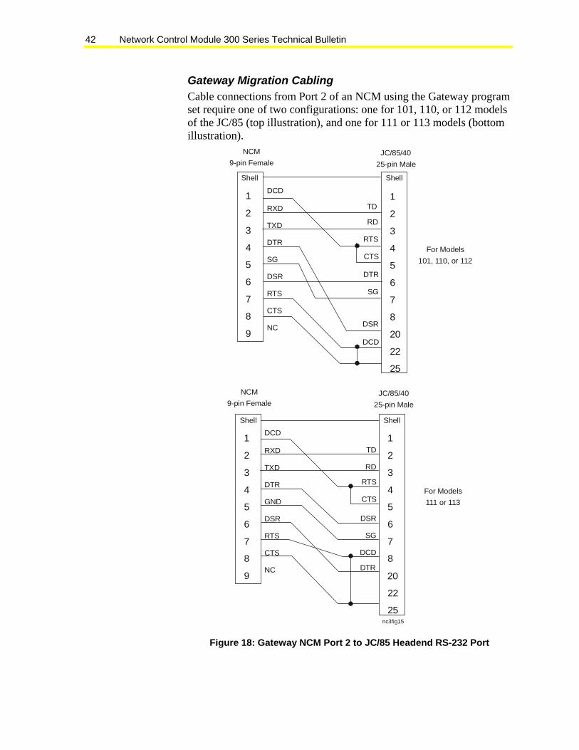
Gateway Migration Cabling Cable connections from Port 2 of an NCM using the Gateway program set require one of two configurations: one for 101, 110, or 112 models of the JC/85 (top illustration), and one for 111 or 113 models (bottom illustration).
1
2
3
4
5
6
7
8
9
DCD
RXD
TXD
DTR
SG
DSR
RTS
CTS
NC
NCM9-pin Female
1
2
3
4
5
6
7
8
20
22
25
JC/85/4025-pin Male
For Models101, 110, or 112
1
2
3
4
5
6
7
8
9
DCD
RXD
TXD
DTR
GND
DSR
RTS
CTS
NC
NCM9-pin Female
1
2
3
4
5
6
7
8
20
22
25
JC/85/4025-pin Male
For Models111 or 113
nc3fig15
Shell
TD
RD
RTS
CTS
DTR
SG
DSR
DCD
TD
RD
RTS
CTS
DSR
SG
DCD
DTR
Shell
Shell Shell
Figure 18: Gateway NCM Port 2 to JC/85 Headend RS-232 Port
Network Control Module 300 Series Technical Bulletin 43
S2 Migration: Table Top Modem The TTM-10n TableTop Modem provides an interface between the RS-232 Port 2 on the S2 Migration NCM and one JC/85 communications trunk. A TTM-10n modem consists of an external power supply, a circuit board with enclosure, and one master modem card. Three models of the TTM-10n are available:
• TTM-101: Provides the interface necessary to communicate to an 18 AWG proprietary, shielded, twisted-pair trunk. A TRM-101 comes mounted to the printed circuit card and is available for single trunk applications only.
• TTM-102: Provides the interface necessary to communicate to a dedicated leased type 3002 phone line. A DPM-101 comes mounted to the printed circuit card.
• TTM-103: Provides the interface necessary to communicate on a JC/LINK Generic Bridge. The Rolm® bridge version is not available.
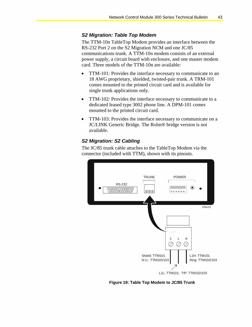
S2 Migration: S2 Cabling The JC/85 trunk cable attaches to the TableTop Modem via the connector (included with TTM), shown with its pinouts.
S L H
TRUNK POWER
RS-232
Shield: TTM101N.U.: TTM102/103
L1H: TTM101Ring: TTM102/103
L1L: TTM101; TIP: TTM102/103
200tc20
Figure 19: Table Top Modem to JC/85 Trunk

Network Control Module 300 Series Technical Bulletin 44
Cable connections from the TTM101, TTM102, and TTM103 to the S2 NCM Port 2 require the following cable:
1
2
3
4
5
6
7
8
9
DCD
RXD
TXD
DTR
GND
DSR
RTS
CTS
NC
NCM9-pin Female
2
3
4
5
6
7
8
20
S2 (TTM)25-pin Male
Shell Shell
In
In
In
In
Out
Out
Out
In
In
Out
Out
Out
In
Out
nc3fig17
Figure 20: Table Top Modems to Port 2 of the S2 NCM
Software Setup Several components integrate software and hardware into a system.
• The Software Architecture Technical Bulletin (LIT-636010) provides an overall guide to objects and attributes.
• NCSETUP for Windows operating system, described in the NCSETUP for Windows Technical Bulletin (LIT-6360251d), establishes the NCM’s configuration and parameters in the non-volatile RAM. This information sets the archive data path, the port designations and values, the program set downloaded to the NCM, dial-up phone numbers when applicable, and other parameters.
• The NCM Definition window (Figure 21) identifies the NCM to the system. The process also correlates non-volatile RAM parameters, maps, associated graphics, and help screens to the defined NCM. The Operator Workstation User’s Manual describes how to define hardware objects.

Network Control Module 300 Series Technical Bulletin 45
Definition Window Identify the NCM to the system by entering data into the attribute fields on the Definition window. The figure below shows the window as seen on the OWS; a description of each attribute follows.
If the Definition window is brought up from an existing object, then all of the fields are filled in with the data from that object.
Fields that allow the data to be modified have the field value boxed in. When a field entry is modified, the new value is immediately verified when the field is exited.
For information on how to define the NCM with Graphic Programming Language (GPL) or JC-BASIC, refer to the Graphic Programming Language Programmer’s Manual and JC-BASIC Programmer’s Manual.
Item Edit View Action Go To Accessory Help
Graphic Symbol #
Operating Instr. #
0
0
HDQTRS
NCM Definition
DEVICES DEVICES
Object NameExpanded IDNC Language
NCM-1NCM-1 IN MECH ROOMENG
HardwareNC Subnet AddressNC Node AddressPort 1 TypePort 2 TypeNT Baud Rate
13
N2
9600
Port 1 Baud RatePort 2 Baud Rate
200tc22
Figure 21: NCM Definition Window

Network Control Module 300 Series Technical Bulletin 46
Table 17 describes the fields in the NCM Definition window.
Table 17: NC Definition Window Fields Field Description Object Name Enter any valid 1-8 character string. The object name must not presently exist under the
system name. Expanded ID Enter any valid 0-24 character string. NC Language
Enter the first three letters of the language from which to draw the text file that appears on screen; ENGlish, DEUtsch, FRAncais, ESPanol, ITAlian.
Graphic Symbol #
If a graphic symbol has been composed to associate with this object, enter the number of the graphic symbol (1-32767). Zero means no graphic symbol is associated with this object.
Operating Instr. #
When Help is selected for this object, a notepad appears containing user-modifiable operator instructions. Enter the number (1-32767) to reference the desired notepad. Zero means no operator instructions are associated with this object.
NC Subnet Address
This is the subnet containing the NCM being set up. This field is also known as the Gate. Valid options are 1-254. However, enter a 1 except when using a Metasys Ethernet Router, or when connecting to the Ethernet LAN directly. For Ethernet Router details, see the Metasys Ethernet Router Technical Bulletin (LIT-6295035). For details on Ethernet LAN, refer to the N1 Ethernet/IP Network Technical Bulletin (LIT-6360175). The factory default is 1.
NC Node Address
This field shows the NCM’s node address on the N1 LAN (1-254). If an ARCNET card is installed, this address is automatically configured on power up to agree with the hardware address switches on the ARCNET card. If the hardware address is changed, the NCM must be reset to recognize the new settings. Do not use NCSETUP for Windows operating systems to enter an address that is different from the ARCNET card switch address. WNCSETUP can temporarily override the hardware address setting, but the address is reset to the ARCNET card switch address if the NCM is reset. Note: The Fire-Net NCM (NU-NCM300-FIRE or NU-NCMFIRE-1) must use Node Addresses 70 through 79. When this NC Type is used on a network, no other Node type should use this range of node addresses. When using NCSETUP for Windows operating systems to set up an Ethernet/IP NC, only the tool configures the Gate and Node addresses. The switches on the Network Interface Card (NIC) set no information.
Port 1 Type For the NCM300/350, Port 1 is the integrated N2 circuit. Accept the default value of N2. The NCM Definition window allows other options. However, Port 1 refers to the integrated N2 connection. You must enter N2 for the port to function. No internal check is made to ensure that N2 was selected.
Port 2 Type (N2, L2, S2, JC85, Allen-Bradley Data Highway [ABDH], N2E, or blank) If you enter S2 as the Port 2 type, a Baud Rate field appears with a valid range of 4800 or 9600. If you enter JC85 as the Port 2 type, a Baud Rate field appears with a range of 1200 to 19,200 in the standard baud increments. The best performance is achieved at 9600 baud. ABDH can be either 9600 baud or 19,200 baud. For devices that connect to this RS-232 port, designate this port type as Blank. For the Operator Terminal program set, designate this port type as Blank. To define the device that connects into the RS-232 port, it is necessary to call that particular device’s Definition window (for example, a directly connected OWS’s Definition window).
NT Baud Rate
(1200, 2400, 4800, 9600) Default is 9600. The Network Terminal transmits at the default 9600 baud. NT Port options are provided to accommodate NT Emulator connections. The Emulator connects to either the NT port via the NT jack or to the DB9 connection on Port 4. It can transmit at different baud depending on which external modem is being used. This also sets the Operator Terminal baud if an OT is connected rather than an NT. For more information, refer to Using the NT Emulator section in the Network Terminal User’s Manual.

Network Control Module 300 Series Technical Bulletin 47
Commissioning Overview Commissioning a Network Control Module begins after these conditions have been met:
• You installed the NCM into a mounted enclosure.
• You inspected all field wiring.
• You defined software objects for all the modules.
Refer to the Key Concepts section of this document and the Universal Packaging Module Technical Bulletin (LIT-6363070) for information on the above steps.
The general commissioning tasks are:
1. Set N2 End-of-Line (EOL) switches, DRAM memory switches (if applicable), and make the cable connections as necessary.
2. Configure the non-volatile RAM (NOVRAM) file with NCSETUP for the Windows operating system. Refer to the NCSETUP for Windows Technical Bulletin (LIT-6360251d).
3. Confirm proper operation via self-diagnostic tests (indicated by LED lights) and correct responses from the field devices.
No special tools are necessary for commissioning an NCM. To set up NOVRAM, use NCSETUP for the Windows operating system. This requires Metasys software running on an OWS.
Cautionary Notes When commissioning the NCM:
• fasten all field ground wires under the topmost screw. This contacts the ground plate of the EWC enclosure.
• disconnect the battery and cycle power prior to making any changes to the current configuration to ensure the changes take effect. (Cycling power with the battery disconnected clears the memory.)
• disconnect the battery power connector prior to installing any SIMM cards or damage may occur to both the SIMMs and the NCM board
• use a ground strap when working on the NCM ISA cards or SIMMs
• if possible, use three chip SIMMs when expanding the NCM memory. Three chip SIMMs draw less current, extending battery backup time.

Network Control Module 300 Series Technical Bulletin 48
• after installing additional SIMMs, change the memory switch settings to allow the NCM to use the additional memory. See Setting the Memory Switches in this document.
• set the EOL switches both the same, Up or Down, as required for N2 termination or N2 errors may occur
• set the configuration values for the ARCNET or Ethernet card to those shown in this document under NCM Cable Guidelines, NCM N1 LAN Connection. See the configuration guide supplied with the card for details on setting these values.
• after installation is complete, use NCSETUP for the Windows operating system to configure the NCM NOVRAM. If you are using an ARCNET card, the node address of the NCM needs to match the node address on the card. (Addresses used for Fire-Net NCMs are limited. Refer to Appendix A: Fire-Net NCM in this document for information on the Fire-Net NCM.)
• connect the battery as the last step in the installation. The battery should be connected last after installing SIMMs, ARCNET, or Ethernet cards. If the battery is not the last item installed, memory is not cleared and problems can occur during commissioning. (The battery must be connected for battery backup.)
Setting the N2 End-of-Line Switches The End-of-Line (EOL) switches are Switches 7 and 8 (rightmost) of the DIP switch bank located near the power LED (at the top of the board). Switches 7 and 8 must both be in the same position, otherwise errors occur on the N2 Bus. If Switches 7 and 8 are up (in), the NCM is an EOL device. If Switches 7 and 8 are down (out), the NCM is not an EOL device (other modules are daisy-chained both upline and downline of the NCM). Factory default is up (in), which means the NCM is at the end-of-line (as shown in Figure 22).
7 and 8 are EOL switches(EOL shown in).
1 and 2 arememory
configurationswitches
(4 MBconfiguration
shown).
nc3swtch
2 3 4 6 7 8
Figure 22: N2 End-of-Line and Memory Configuration Switches

Network Control Module 300 Series Technical Bulletin 49
Setting the Memory Switches The memory configuration is set by Switches 1 and 2 (leftmost) of the DIP switch bank shown in Figure 22. The four memory switch settings (2, 4, 6, 8, and 10 MB of DRAM) are shown in Table 18. Figure 22 shows a 4 MB memory configuration (Switch 1=down, Switch 2=up).
Table 18: Memory DIP Switch Settings* Total Memory Database
Memory DIP Switch Setting
2 MB 580 KB SW1 = up SW2 = up
1 2 3 4 5 6 7 8 EOL
4 MB 2 MB SW1 = down SW2 = up
1 2 3 4 5 6 7 8 EOL
6 MB 4 MB SW1 = up SW2 = down
1 2 3 4 5 6 7 8 EOL
8 MB (NCM350-8)
6 MB SW1 = Not used SW2 = Not used 1 2 3 4 5 6 7 8 EOL
10 MB 8 MB SW1 = down SW2 = down
1 2 3 4 5 6 7 8 EOL
If the memory configuration is different from the actual SIMMs installed, an LED error may be indicated during the power on self tests. See Troubleshooting in this document. * Memory switches are not used in the NCM350-8. The NCM350-8 comes with 8 MB memory.
NCSETUP for Windows Operating System (WNCSETUP) NCSETUP for Windows operating system (WNCSETUP) is a software utility that sets up and modifies the non-volatile RAM (NOVRAM) configuration. It replaces the DOS version of NCSETUP. WNCSETUP provides several status and diagnostic functions in addition to storing the system paths by which a restarted NCM can call data and applications from archive files.
WNCSETUP is also the utility that establishes to the system what type of NCM (what program set - standard, security, S2 Migration) you are commissioning.
You must have the Metasys system running on the OWS in order to use WNCSETUP. For complete information on WNCSETUP, see the NCSETUP for Windows Technical Bulletin (LIT-6360251d).

Network Control Module 300 Series Technical Bulletin 50
NOVRAM Defaults Table 19 shows the NOVRAM factory defaults for the NCM.
Table 19: NOVRAM Defaults (NCM) Gate Node Port Node Address 1 99 n/a Archive Address 0 0 0 Network Name (blank) Port 3 Baud 19200
Table 20 shows the NOVRAM defaults for the Fire-Net NCM.
Table 20: NOVRAM Defaults (Fire-Net NCM) Gate Node Port Node Address 1 70 n/a Archive Address 1 150 0 Network Name (blank) Port 3 Baud n/a
NOVRAM defaults are downloaded into the NCM during factory testing.
Network Control Module 300 Series Technical Bulletin 51
Hardware Requirements WNCSETUP requires the following hardware to run:
• PC or laptop
• cabling - if the utility is run via the:
- RS-232 Port 2 or 3 on the NCM, the cable could be 9-pin female or 25-pin female on the PC end, based on the type of PC or laptop used. The NCM connection is 9-pin female. See NCM Cable Guidelines in this document.
- N1, then the N1 coax cable is required to connect the PC or laptop to the NCM.
• floppy drive or hard disk
Software Requirements Running WNCSETUP on the NCM requires the following software:
• Metasys software Release 8.0 or later
• Microsoft® Windows® software
Power On Sequence The following LED light sequence occurs when you turn on power to the NCM. (The self-diagnostic LEDs are more fully explained in the Troubleshooting section of this document.)
! IMPORTANT: Install the NU-ROM101 or NU-ROM150 before applying power to the NCM. If either the NU-ROM101 or NU-ROM150 is not installed when power is applied to the NCM, the NCM DRAM and NOVRAM may be corrupted. If the NOVRAM is corrupted, replace the NCM.
1. After applying power, the LEDs may sometimes randomly light during initialization (for approximately 1 second), responding to commanded positions.
2. An LED (LED 1 through 8) flashes as an indication of the firmware revision (for example, LED 1 for Revision 1 of the NCM300 and NCM311, or LED 8 for Revision 1 of the NCM350 and NCM361).
3. Then all LEDs flash simultaneously, followed by each LED flashing in sequence, starting with the LED closest to the top of the board (by the N2 connector).
4. The software then executes tests for EPROM checksum and DRAM read/write, followed by other startup diagnostics. LED 8 is on during this test.

Network Control Module 300 Series Technical Bulletin 52
5. If no errors occur, the LEDs remain off (except Power). If errors occur, they are displayed. Refer to Appendix B: NCM Maintenance in this document for more information. Failure of Test 1 or 2 causes that LED to flash until power is cycled; the remaining error LEDs are displayed only momentarily. (If necessary, use the LOGFILE Command on WNCSETUP to view the startup errors.)
6. After successfully completing the startup tests, all the LEDs light for about 5 seconds for the NCM300 and NCM311, or about 22 seconds for the NCM350 and NCM361.
7. The NCM’s node address (decimal) is then indicated as a binary number using LEDs 1 through 8. Bit 0 corresponds to the least significant digit (LED 1), Bit 7 to LED 8. The address remains lit for 5 seconds. (Example: LED 1, 2, and 6 On indicates a node address of 35.)
8. For an NCM350, the node address, network name, and IP address are displayed on Port 4 if a VT100 emulator is connected at 9600 baud when the NCM350 starts up requiring a download.
9. If the NCM has been previously downloaded, with the battery connected, it begins in its operational state. If no download has been performed, the NCM requests a download. LED operation is switched to hardware use for RECV/XMIT status of the serial channels.
NCM Idle Time Idle Time Percent Calculation The NCM calculates NCM idle time percent with the following equation every 5 seconds:
Idle Time % = Last Idle Time % + (Change in Idle Time % * 0.04)
where Change in Idle Time = last idle time percent subtracted from the present idle time percent
Even when there are large changes in idle time, there is a delay before the Idle Time % reflects these changes. For example, if the last idle time percent was 100 and the present idle time percent is 0 the equation would be:
Idle Time % = 100 +[(0 – 100) * 0.04]
Idle Time % = 100 + (-100 * 0.04)
Idle Time % = 100 + -4
Idle Time % = 96
Almost 100 seconds after the idle time goes from 100 to 0 (and stays 0), the Idle Time % reaches fifty percent.

Network Control Module 300 Series Technical Bulletin 53
Idle Time in the Task Utilization Tool The idle time displayed in the Task Utilization tool does not have the same value as the NCM Idle Time. The NCM Idle Time is a filtered value (see the Idle Time Percent Calculation section). The Task Utilization tool displays the idle time average over a 15-second span.
Specifications and Order Codes Table 21: Specifications
Feature Specification Supply Voltage 90 to 240 VAC, 670 to 250 mA, 50-60 Hz Power Consumption 60 VA (maximum), 25 VA (typical) at 50-60 Hz Ambient Operating Conditions
0 to 50°C (32 to 122°F) 10 to 90% RH noncondensing
Ambient Storage Conditions 0 to 50°C (32 to 122°F) 10 to 90% RH
Internal Batteries Shelf life (disconnected): 10 years Typical working life, with power: 5 years Maintains RAM programs/data for up to a 72-hour power failure Automatically recharges from NCM
Serial Interfaces One optically isolated RS-485 interface for N2 connection; 9600 baud pluggable, 3-position connector Three RS-232-C ports (300 through 19200 baud): two DB9 male connection one DB9 male/RJ-12 connection
Processor 80386 @ 16 MHz Memory Options Total Memory Database Memory SIMM Type/Quantity 2 MB 580 KB none
4 MB 2 MB 1 MB SIMM (2) 6 MB 4 MB 1 MB SIMM (4) 8 MB 6 MB none 10 MB 8 MB 4 MB SIMM (2)
- 1 or 4 MB SIMMs should be 9 bits wide on a 30-pin SIMM with a speed rating of 100 nS or faster. - 3 chip SIMMs use less power than 9 chip SIMMs (that is, this extends your battery backup time). See Table 6, in the ISA Bus Cards, Battery Pack section of this document. - Memory is always upgraded in pairs (banks) of SIMMs.
Dimensions (L x W x H)
32 x 15 x 14 cm (12.4 x 6.0 x 5.5 in.)
Shipping Weight 1.9 kg (4.2 lb) Agency Listings NCM300/350 UL 916 Listed
CSA C22.2 Certified FCC Class A UL 864 Listed
NCM311/361 Meets EMC directive 89/336/EEC FCC Class A
Note: The NCM350-8 does not have memory options. The supplied memory is: Total Memory = 8 MB; Database memory = 6 MB; SIMM type/quantity = none.

Network Control Module 300 Series Technical Bulletin 54
Table 22: Order Codes Description Product Code
Number Network Control Module 350-8 NU-NCM350-8 Network Control Module 350-8 (Repair) NU-NCM350-708 Network Control Module 361-8 NU-NCM361-8 Network Control Module 361-8 (Repair) NU-NCM361-708 Network Control Module 300 (Repair) NU-NCM300-701 Network Control Module 311 (Repair) NU-NCM311-701 Network Control Module 350 (Repair) NU-NCM350-701 Network Control Module 361 (Repair) NU-NCM361-701 NCM300 to NCM350 Upgrade Kit (Requires NU-NCM300-1, Rev. B or Later) NU-ROM150 NCM311 to NCM361 Upgrade Kit (Requires NU-NCM311-1) NU-ROM150 TableTop Modem (Johnson Controls Proprietary Line) TTM101-0 TableTop Modem (Leased Line) TTM102-0 TableTop Modem (JC/LINK Generic Bridge) TTM103-0 N1 LAN Card for NCM300 NU-NET101-0 LONWORKS Interface Card (N2E-TP78) NU-NET201-0 LONWORKS Interface Card (N2E-FTT10) NU-NET202-0 LONWORKS Interface Card (LON-FTT10) NU-NET203-0 or
NU-NET203-1 Ethernet Card for NCM350 NU-NET301-0 Replacement Power Supply NU-PWR300-0 Replacement Battery Pack NU-BAT300-1 Battery Tester (ordered from vendor. See the System Inspection, Ordering and Using the Battery Tester section in Appendix B for details.)
NU-BATTST-0
Replacement Cable for Battery Tester (ordered from vendor. See the System Inspection, Ordering and Using the Battery Tester section in Appendix B for details.)
NU-BATCBL-0
RS-232 to RS-485 Converter MM-CVT101-0 L2 Bus Repeater Y500A-701 NCM300 SIMM Upgrade NU-ROM101-1 Note: If you return the NCM for repair, include the battery pack with the return shipment. For further information on returning a defective NCM, refer to the Warranty section of the Standard Terms page in your current Cost Schedule. For specification and ordering information for the Fire-Net NCM, refer to the Appendix A: Fire-Net NCM section of this document.

Network Control Module 300 Series Technical Bulletin 55
Detailed Procedures Replacing an NCM401 with an NCM300
If objects have been added online, they are lost if the NC file is recompiled. To avoid losing these objects, first perform an NC upload, then a decompile (using UNDDL), and finally make the port changes to the decompiled file.
To replace an NCM401 with an NCM300:
1. Remove any configured devices from Port 2 in the Global DDL file.
2. Move the S2 trunk from Port 1 to Port 2 in the Global DDL file.
3. Specify 2 for the S2 trunk number parameter for migration devices (DSC8500, FPU) in the NC file.
4. After recompiling the Global DDL and NC files, all GPL and JC-BASIC processes must be translated.

Network Control Module 300 Series Technical Bulletin 56
Troubleshooting Troubleshooting the NCM
This section provides basic troubleshooting information. Additional NCM maintenance and hardware troubleshooting information is located in Appendix B: NCM Maintenance in this document.
If you cannot resolve your problem after checking or performing the procedures in this section and in the Appendix B: NCM Maintenance section, contact the Field Support Center prior to submitting a Return Materials Authorization (RMA). For information on the NCM100 power supply, see Appendix C: NCM100 Power Supply Troubleshooting in this document.
The following tips can help when troubleshooting the NCM300/350:
• When installing the new NU-ROM150, be careful not to touch the edge connector with your fingers. Touching the edge connector can leave behind oils or corrosive residues that can cause damage to the connector.
• Do not clean the edge connectors of NU-ROM101 or NU-ROM150 cards.
• If necessary, use contact cleaning wipes to clean the edge connectors of ISA cards or SIMMs. Do not use erasers to clean edge connectors.
Communications If you are using the Ethernet/IP N1 LAN, refer to the N1 Ethernet/IP Network Technical Bulletin (LIT-6360175) for details.
NCM Resets or Shows Error Codes when Using Ethernet If you are using Ethernet boards and the NCM resets and/or shows error codes for packet drivers, try using the NE2000 generic packet driver (NE2000AT.FLH). This driver may be referred to as the CRYNWR driver and is included with the NCM350 since January 1997. Use NCSETUP for Windows operating systems to make changes to the NCM.

Network Control Module 300 Series Technical Bulletin 57
NCM350-8 Resets or Malfunctions Due to Circuit Shorting The Erasable Programmable Read-Only Memory (EPROM) covering on NCM350-8s is conductive to shield electromagnetic signals from the NCM. The ROM150 cover may come in contact with the NCM motherboard or the card installed in the first ISA option slot. If this happens, some portion of either circuit can become shorted and cause the NCM to reset or exhibit other signs of malfunction.
Note: Newer NCM350-8 ROM150 covers have factory-installed insulation that prevents shorting. Before proceeding with the following steps, check to see if your NCM350-8 has factory-installed insulation.
1. Before applying power to the NCM, check the top edge of the ROM150 cover to make sure it is not hooked under one or more of the component solder trails from the board being inserted. If the cover is hooked, remove and reinsert the board while holding the cover away from the bottom of the board.
2. Check that the ROM150 cover is not bending to touch one end of the motherboard. Move the cover away from the motherboard before applying power to the NCM.
Note: Inspection and proper insulation of ISA boards and enclosure prevent most shorting instances. To ensure shorting does not occur, apply electrical tape to the top and lower edges of the ROM150 cover. Remove the cover and measure the three edges (one on top and two on the bottom). Cut tape to those lengths and apply to the cover so each piece of tape straddles the edges. Half of the tape should be on either side of the surrounding edge.
If You Cannot Communicate at All with the NCM Note: The following section applies only if you are using an NCM on the ARCNET N1 LAN.
Unless the NCM has worked previously, or only one NCM on the N1 is not communicating, this symptom points to an error in the software configuration, ARCNET card setup, or cabling.
1. Ensure that the NCM is correctly addressed on the OWS (the NCM address must match what the OWS thinks it is, and the NCM archive address must point to the appropriate archive PC).
2. If the N1 transmit LED (at the top of the ARCNET card) blinks frequently while yielding intermittent or no communication, the N1 is constantly reconfiguring. This is a clue that there are duplicate addresses on the LAN or that there is a problem with the N1 wiring. Make sure that the N1 connectors do not short to the NCM enclosure or other metal grounds.

Network Control Module 300 Series Technical Bulletin 58
3. If using a Thomas-Conrad ARCNET board, ensure that the operating mode switch setting is set to compatible.
4. Ensure that the physical configuration of the system is within guidelines. These include cable lengths, type, integrity, end-of-line terminators, N1 and N2 connections, the number of devices on each trunk, and the proper selection of the ARCNET bus/star configuration. Related Commissioning Problems, at the end of this section, includes notes on cabling and EOL terminations. In addition, refer to: N1 ARCNET Local Area Network Technical Bulletin (LIT-636017), and N2 Communications Bus Technical Bulletin (LIT-636018).
• Configurations marginally outside specification have occasional failed bootups, such as one in five. A different NCM may increase or decrease the failure rate of a marginal configuration.
• If, in the NCM Diagnostics N1 Statistics window, the RECONS value remains steady, and there are no duplicate addresses, the N1 wiring is probably good.
5. Inspect the error logs (both in the NCM and the OWS) for the source of the problem.
• For the NCM, use WNCSETUP - LOGFILE command
Note: If the NCM continuously reboots - and erases the Error Log-run WNCSETUP and answer No to the Reboot on Error prompt. Make sure to reset the prompt to Yes when the problem is resolved.
• For the OWS, read the ERRORLOG.TXT file - NC Task/Error Log; Troubleshooting Guide Technical Bulletin (LIT-636328).
6. Attempt a direct connect communication to the NCM.
If You Can Communicate with the NCM but Cannot Download Properly You can download from an OWS to an NCM though a serial card or internal modem in an ISA slot if you are using an NCM350 or NCM361 with Metasys Release 8.0 or later software. If you are using an NCM300 or NCM311, you must download before the OWS can communicate to the ISA slot. Fire-Net NCMs can be downloaded only from an Underwriters Laboratories®, Inc. (UL) (Fire) OWS.
If you are having problems downloading through Port 2, 3, 5 or 6:
1. Test the download procedure with a known, good NCM.
2. Test the download procedure with a known, good OWS.

Network Control Module 300 Series Technical Bulletin 59
3. Test the download procedure with a known, good cable (particularly check the N1 connections) and a known, good ARCNET card.
4. Inspect the error logs (see Step 4, in previous section).
5. There may be software issues preventing the download. Here are some things to consider:
• If the database is one that previously uploaded, but does not now download, an UNDDL of the database provides a small amount of cross-checking and can determine if any of the object databases (but not most feature databases) is flawed. UNDDL also determines if a database even exists for the NCM (for example, the user uploaded to a different OWS and the current one does not have a database). If UNDDL finds an error, edit the .UND file; renaming and recompiling it may fix the database.
• If the database was modified after an upload (DDL incremental or Graphic Programming Language [GPL]), a heavily loaded NCM may fail due to lack of memory.
• If DDL or GPL was aborted (CNTRL C, PC reboot) during execution, the database is corrupted and a recompile is necessary to create a good database.
• A DDL recompile necessitates retranslating of GPL processes and a recompile of JC-BASIC.
• If using CS objects, the correct model files must exist on the OWS.
Network-Related Field Checks Follow these steps for network-related field checks:
1. After confirming the proper node address, test the NCM’s ability to communicate over the N1 LAN. Transmit (XMIT) and Receive (RECV) LEDs should respond to activity. (Also see N1 End-of-Line Termination Notes in the Related Commissioning Problems section.)
2. Next, for a Standard Functionality NCM, verify that the device is being polled on the N2 Bus. This is evident if the XMIT LED lights, which indicates that the NCM is sending a poll.
Notes: The S2 Migration and JC/85 Gateway networks connect to a Metasys system via the RS-232 port. For those networks, see the field checks in the Troubleshooting section.

Network Control Module 300 Series Technical Bulletin 60
If you are using an internal modem on Port 5 or Port 6, there are no LEDs. It might be helpful to turn on the speakers to check for operation.
• If the RECV and XMIT LEDs respond irregularly, and the Focus Windows list all the devices on the N2 trunk for the NCM as being Offline, the polarity of the N2 wire connection may be reversed. Inspect the N2 wiring to ensure that the same color wire exits at the TBC terminal as at the originating end of the N2 trunk. For further information, refer to N2 Communications Bus Technical Bulletin (LIT-636018).
• If the XMIT LED never lights, check the green RECV LED.
• If the RECV LED does not light, the NCM is not connected to the N2 Bus. Follow Steps 3-5 (below) to troubleshoot the N2, or refer to the N2 Communications Bus Technical Bulletin (LIT-636018).
• If the RECV LED does light without the XMIT LED ever responding, perhaps no messages are being addressed to the NCM.
• Ensure that the system is configured to poll the NCM by checking the address via WNCSETUP.
3. Check the EOL switches. If, by accident, more than two EOL switches are set on a heavily loaded network, normal communication could be disrupted (erratic or non-functional). Also, if Switch 7 is not in the same position as Switch 8, N2 communication is impaired.
4. Attempt to isolate the N2 device nearest the panel. Establishing communication to that device indicates that the N2 interface is operating correctly, and the problem lies in the field wiring.
5. Cycle power to the NCM. Check the self-diagnostics LEDs for indications of a failure: A faulty N2 connection is one reason that LED 4 lights.
Port Field Check: RS-232 Port Follow these steps to field check ports:
1. If not communicating via the RS-232 port, check for the proper cable configuration and connections. Review the cable diagrams in the NCM Cable Guidelines section of this document.
2. Verify that baud is compatible with the device. Use the WNCSETUP routine to monitor and change the baud, if necessary.

Network Control Module 300 Series Technical Bulletin 61
3. Cycle power to the NCM. An LED 4 error indicates that a port is failing. Use WNCSETUP menu INFORMATION command to find out which port is failing.
Additional Field Checks: S2 Migration Connections 1. Check that the TableTop Modem LEDs are blinking (not steady
On or steady Off) before investigating problems with the RS-232 port.
2. Check that the S2 software was downloaded (WNCSETUP menu NOVRAM command).
For problems that occur with the S2 Migration network, refer to:
• S2 hardware: Using Diagnostics chapter (LIT-120159) of the Operator Workstation User’s Manual
• S2 software:
- Using Diagnostics chapter (LIT-120159) of the Operator Workstation User’s Manual
- Diagnostics Feature, S2 Statistics
Additional Field Checks: JC/85 Gateway Connections 1. Because the JC/85 polls the Gateway NCM, the RECV LED
should light before the XMIT. If the XMIT LED lights first, ensure that the cable between the JC/85 and RS-232 port is not backwards.
2. Check that the JC/85 software was downloaded (WNCSETUP menu NOVRAM command).
For problems that occur with the JC/85 Gateway network, refer to:
• JC/85 hardware: JC/85 Gateway Application Note (LIT-6363147)
• JC/85 software: JC/85 Gateway Application Note (LIT-6363147)
Additional Field Checks: RS-232 Remote Modem Applications • (For 2400 baud modems, and above) Ensure that the NOVRAM
parameters are correctly loaded.
• (For Multi Tech® modem) Ensure that the remote modem switch settings are correct. Refer to switch settings in the Leased Line Modem Application Note (LIT-6363141).
Network Terminal Upon power up, the NCM’s diagnostic LEDs indicate internal errors. An LED 4 error indicates that a port is not functioning. Use WNCSETUP Information command to find out which port is failing.

Network Control Module 300 Series Technical Bulletin 62
If Port 4 has failed, see the Network Terminal Technical Bulletin (LIT-636012) for further troubleshooting.
WNCSETUP Field Checks One reason that an NCM appears not to function properly is that the NCSETUP for Windows software version used to configure it is not appropriate to the version of Metasys software loaded in the NCM.
An NCM300 requires Metasys Release 6.0 (or later) software. An NCM350 requires Metasys Release 8.0 or later. NCSETUP for Windows is contained within the Metasys Person-Machine Interface (PMI) software. On the Help menu of NCSETUP for Windows, click About for version and copyright information.
Failing to use corresponding WNCSETUP and Metasys software versions may result in these symptoms:
• Files do not download from the configuring PC to the NCM.
• Files do not upload from the NCM to the PC.
• The NCM does not talk on the N1 LAN.
• The NCM runs out of acquired memory.
• The NCM continuously reboots or reboots on its own.
If these symptoms appear, rerun WNCSETUP after ensuring that the correct Metasys release software (including its corresponding WNCSETUP version) has been loaded onto the hard disk, and that no other version of WNCSETUP is accessed. Refer to the NCSETUP for Windows Technical Bulletin (LIT-6360251d).
Downloading NCMs across Ethernet/Ethernet to ARCNET Network with a Router NCMs with firmware prior to 8.02 flash ROM running on an Ethernet or Ethernet to ARCNET network may experience download failures. During download, NCM response messages are lost over the Ethernet. The OWS concludes that the NCM is not receiving data, tries to download two more times, then fails the download.
Workarounds include the following:
• If you have an Ethernet to ARCNET network, leave the archive OWS on the ARCNET side of the network.
• Disconnect or segment your Ethernet nodes from the customer’s network (the load on the customer’s network brings the problem to the surface).

Network Control Module 300 Series Technical Bulletin 63
Solutions are the following:
• Contact the Field Support Center (FSC) and ask for the NCM Download Patch. Install the patch and add EADnldTimer and EADnldWindows to the Metasys INI file. See the Optional METASYS.INI File Parameters section of the Metasys Initialization Parameters Technical Bulletin (LIT-636345).
• Replace or upgrade your problem NCMs per Table 23.
Table 23: NCM Solutions Current Problem NCM Replace or Upgrade Action NCM101 Replace with NCM350-8 (8.02 flash ROM). NCM200 Replace with NCM350-8 (8.02 flash ROM). NCM300 Upgrade to NCM350-8 (8.02 flash ROM). NCM350-1 (prior to 8.02 flash ROM)
Update the flash ROM to 8.02.
Related Commissioning Problems The following problems are also related to commissioning.
RS-232 Port Cable Failed downloads can result from incorrect cabling between the configuring PC and the NCM port. Recheck cable configurations, as shown in the NCM Cable Guidelines section of this document.
RS-232 Baud Failed downloads also can result from incompatible baud between the configuring PC and the NCM Port. The RS-232 port defaults to a baud of 19200. After the NCM has been successfully configured, you can change the baud within the ranges of 300 to 19200. However, if the NCM RS-232 port is changed from the default of 19200 and WNCSETUP must be performed again, the new baud must be used or WNCSETUP fails.

Network Control Module 300 Series Technical Bulletin 64
N1 Statistics Diagnostics System representatives have assumed their NCM was faulty due to the appearance of error counts during the N1 Statistics Diagnostics. See the Using Diagnostics chapter (LIT-120159) of the Operator Workstation User’s Manual. Some error counts are typically generated when running the diagnostics. Determining when the normal range of errors has been exceeded is somewhat difficult because of site and configuration variables.
If, when running the diagnostics, you believe there is an excessive number of errors, regard the errors as a warning to test the functionality of the NCM. Assume that a properly functioning NCM is good, and there is no need to return it. A rule of thumb is that NCMs typically keep diagnostic errors around 0.1% or less.
Remember, in situations where diagnostic errors are greater than 0.1%, there can be causes other than the NCM. If the errors increase as fast as the number of transmits and receives process, something is likely wrong.
N1 End-of-Line Termination Notes Keep the following items in mind for N1 End-of-Line Termination:
• Use 93-ohm terminators and RG-62 type cable for the ARCNET N1 LAN. Do not use RG-62 type cable for Ethernet networks.
• The OWS ARCNET card may contain an internal EOL termination resistor.
- To prevent adding a third resistor to the network, determine whether your OWS ARCNET card has an internal EOL resistor. Refer to your ARCNET card manual.
- If the ARCNET card has an internal resistor, make sure that it is removed or disabled. Refer to your ARCNET card manual. Ensure this either by positioning the OWS at the end of the line, or jumper the board to disengage the EOL resistor, and adding a resistor at the proper position.
- Always use an External 93-ohm terminator and a coax tee connector to terminate at the end of the lines.
Notes: On the approved active hubs, the cables are terminated internally. On the approved active links, external terminators are required for each EOL connection.

Network Control Module 300 Series Technical Bulletin 65
• Use these methods to check the termination LAN resistance:
- If the Network consists of NCM101/401/200 series controllers and high DC resistance ARCNET cards, power down the network and, with the LAN cables connected, insert a T-connector and measure the conductor-to-shield resistance. The value should nominally be 46.5 ohms, with an acceptable range of 46 to 54 ohms. If properly terminated, it does not matter how many NCMs are online. Readings less than 46.5 ohms indicate that more than two terminations are on the LAN. A reading of 93 ohms indicates that only one termination is on the LAN. N1 LAN confidence-level tests are found in the Network Communications, JC/80 Coax on N1 LAN Application Note (LIT-6363142).
- If the network contains low DC resistance ARCNET cards such as the NET101, then these nodes must be disconnected prior to making the resistance measurement indicated above, or the value measured is lower (1 to 54 ohms).
- If available, use a time-domain reflectometer to estimate where a problem or discontinuity exists.
- As a general N1 termination check, the outside conductor must be isolated from the earth ground for proper operation. Test N1 connections (including barrel connectors) for possible shorts from the outside conductor shield to ground. The resistance should be in the Mega-ohm range.
VMA14x0 Controllers Cycle Online and Offline VMA14x0 controllers cycle online and offline when remotely connected to an NCM via an S.I. Tech™ 2110 Optical Asynchronous Mini Bit-Driver® modem with a serial number lower than 044301. This problem is specific to the AP-VMA14x0 controllers. Devices communicating via N1 are not affected. To solve the problem, order a replacement with serial number 044301 or higher from S.I. Tech at www.sitech-bitdriver.com. If you received an old style S.I. Tech Bit-Driver as part of a new construction order, contact Johnson Controls for possible credit.

Network Control Module 300 Series Technical Bulletin 66
Short Haul Modems (Line Drivers) A short haul modem has electronic drivers for two dedicated twisted pair Electronic Industries Alliance (EIA) interface devices (for example, NCM to Remote Terminal) where no telephone line exists. Some of the ways in which these modems are used result in noise being picked up by the NCM. For example, if the remote terminal is a portable PC that is removed after use, then the open terminal can be a source of noise to the NCM. Alternatively, if the modem is used in a printer application, the unused receive terminals on the NCM end may pick up noise.
Short haul modems may not be reliable for mission critical applications. Do not use them in applications that cannot tolerate any downtime, such as hospital, pharmaceutical, or other critical industrial applications.
Short haul modem pairs must be identical to communicate. If you replace one modem, make sure your replacement is identical to the remaining modem or replace them both.
Precautions When Using Short Haul Modems (Line Drivers) Any short haul modem used in Metasys System operation must have DC electrical isolation between the two output pairs and the RS-232 port built within the modem. This is not the same thing as noise or transient suppression. While transient suppression is acceptable, only models of modems having the electrical isolation are allowed.
Conventional trunk noise reduction wiring goes a long way toward preventing this problem. Shielded twisted pair wires with proper noise grounding techniques cure most problems before they can occur. For example, earth ground the shield on the NCM side in applications where a remote terminal is used. Consider using a soft ground with a 560 pf capacitor between the remote end of the shield and earth.
In cases where the trunk is set up for multi-drop use, such as a portable remote terminal, attach an end-of-line resistor at the farthest termination from the master device. A 220-ohm 1/4-watt carbon film resistor should be sufficient. One resistor should be attached to each twisted pair, receive and transmit circuits. These resistors, and the internal impedance of the master device, prevent a high-impedance antenna effect from bringing unwanted noise into the system.
In extremely noisy conditions, connect a Johnson Controls line conditioning device/noise limiting capacitor (ACC-22-0) between the two receive wires at the NCM side of the modem. If the modem is used as an out-going signal only, such as in a printer application, the unused receive terminals on the NCM end should be shorted together to prevent noise pickup.

Network Control Module 300 Series Technical Bulletin 67
NCM Power-up LEDs IMPORTANT: Install the NU-ROM101 or NU-ROM150 before applying power to the NCM. If either the NU-ROM101 or NU-ROM150 is not installed when power is applied to the NCM, the NCM DRAM and NOVRAM may be corrupted. If the NOVRAM is corrupted, replace the NCM.
LED indicators supply evidence of the module’s condition. There are ten LED indicators on an NCM (as shown in Figure 23): Power, Battery Status, and four sets of transmit (XMIT) and receive (RECV) LEDs:
• N2 Bus circuit (LEDs 1 and 2)
• Port 2 (LEDs 3 and 4)
• Port 3 (LEDs 5 and 6)
• NTU Port 4 (LEDs 7 and 8)
During startup, LEDs 1-8 function as error indicators for self-diagnostics. Transmit and receive LEDs may also be provided for the N1 LAN and are located on the ARCNET board.

Network Control Module 300 Series Technical Bulletin 68
ncmblwup
POWER
CONFIG.
END OFLINE
ISASLOTS
I
III
a
b
ON
1 2 3 4 5 6 7 8
IN
OUT7 8
1 2 3 4 5 6 7 8
COMM-PORTS
DS3
DS4
DS5
DS6
DS7
DS8
DS9
DS10
II
III
IV
I
LED 1LED 2
LED 3LED 4
LED 5LED 6
LED 7LED 8
Power LED
BatteryStatus LED
BAT.FAULT
Figure 23: LED Indicators on the NCM

Network Control Module 300 Series Technical Bulletin 69
Self Diagnostics: Microprocessor Indicators and Troubleshooting NCM power up self-diagnostics follows this sequence:
1. After applying power, the LEDs randomly light during initialization (for approximately 1 second), responding to commanded positions.
2. An LED (LED 1 through 8) flashes as an indication of the NCM’s firmware revision (for example, LED 1 for Revision 1 of the NCM300 or NCM311, or LED 8 for Revision 1 of the NCM350 or NCM361).
3. All LEDs flash simultaneously, followed by each LED flashing in sequence, starting with the LED closest to the top of the board (by the N2 connector).
4. The software executes tests for EPROM checksum and DRAM read/write, followed by other startup diagnostics. LED 8 is on during this test.
5. If no errors occur, the LEDs remain off (except Power). If errors occur, they are displayed as shown in Table 24. Failure of Test 1 or 2 causes that LED to flash until power is cycled; the remaining error LEDs appear only momentarily.
(If necessary, use the NCM miscellaneous diagnostic tests on NCSETUP to view the startup errors.)
6. After successfully completing the startup tests, all the LEDs light for about five seconds.
7. The NCM’s node address (decimal) is then indicated as a binary number using LEDs 1 through 8. Bit 0 corresponds to the least significant digit (LED 1); Bit 7 to LED 8. The address remains lit for 5 seconds. (Example: LEDs 1, 2, and 6 On indicate a NOVRAM node address of 35.)
8. If the NCM has been previously downloaded, with the battery connected, it begins with its operational state. If no download has been performed, the NCM requests a download. LED operation is switched to hardware use for RECV/XMIT status of the serial channels.

Network Control Module 300 Series Technical Bulletin 70
Table 24: Diagnostic LEDs, Descriptions, and Remedies Error LED Description Action LED 1 (flashing) EPROM checksum error Power down, reseat ROM SIMM
(NU-ROM101 or NU-ROM150), and power back up.
LED 2 (flashing) DRAM read/write error If an LED 2 DRAM read/write error occurs, it is followed immediately by a second LED indicator corresponding to the source of the DRAM error. If there is no second LED, there is an on board DRAM error.
Power down. Check the memory switch settings, and reseat the affected DRAM SIMM. Then cycle power.
LED 2 Alone On board DRAM error LED 2 with LED 3 SIMM Slot J4 LED 2 with LED 4 SIMM Slot J3 LED 2 with LED 5 SIMM Slot J2 LED 2 with LED 6 SIMM Slot J1 LED 2 with LED 7 Parity error LED 3 NOVRAM error Power down, reseat NU-ROM101 or
NU-ROM150 ROM SIMM, and power back up.
LED 4 Serial communication error Cycle power. Review the startup results using NCSETUP. If any of the internal loopback tests failed, replace the NCM.
LED 5 ARCNET error (or ARCNET card not installed)
Check the address for the I/O base and memory base. Check the interrupt settings. Reseat the ARCNET board and cycle power on the NCM. (Ignore if ARCNET card is not being used.) If the NCM is a Fire-Net NCM (NU-NCM300-FIRE), both the ARCNET base I/O address and the ISA Slot 1 base I/O address must be set to 2E0 (factory setting).
LED 6 Sanity error The NCM may continue to operate but at a degraded level of reliability. (Time-of-day also may be affected if the sanity test fails.)
LED 7 Clock/calendar error The NCM may not keep accurate time during a power down; replace the NCM.
LED 7 Flashing and Processor Halted
DRAM Parity
LED 8 Battery error Make sure the battery is properly installed. Replace the battery if necessary (see the battery testing procedures).
LED 1 and LED 2 (NCM350 and NCM361 only)
MINIBIOS, ROMDOS, or ROMDISK Checksum error
Replace NU-ROM101 or NU-ROM150 SIMM or update flash.

Network Control Module 300 Series Technical Bulletin 71
NCM Module Field Checks To field check NCM modules:
1. Cycle power to run self-diagnostics. This may clear any internal errors.
2. If an error is indicated by the LEDs, determine whether to replace the module. Possible errors are:
• incorrect node address for the NCM. Check the node address set on the ARCNET card. You can also verify this by viewing the display following the self-diagnostics. If the node number assigned duplicates that of another device’s node number (on either the N1 or N2), a communication error occurs, resulting in erratic (or no) communications transmitted. Reassign a unique node number via NCSETUP.
• 50-60 Hz line frequency is not present. This is one of the conditions checked by the sanity testing and is indicated with an LED 6 error.
• if the power LED turns off (and there is power present at the cable), either the LED is defective (in which case the board still functions properly), or there is a malfunction in the power supply section of the NCM. Turn the power supply off and double check the connections to the power cable. For more information on power supply troubleshooting, see Appendix B: NCM Maintenance.

Network Control Module 300 Series Technical Bulletin 72
NCM300/350 Troubleshooting Refer to Table 25 for general NCM300/350 troubleshooting information.
Table 25: NCM300/350 Troubleshooting Guide Error/Condition Problem Solution NCM300/350 resets continually when any 16-bit adapter card is installed in either ISA slot.
The problem is usually caused by improper installation of ISA boards (for example, installing while power is on). If the device operates normally when an 8-bit adapter card is installed, then the cause of the problem is probably due to the failure of a component used to operate the 16-bit feature.
Use a working 8-bit adapter card if you have one or replace the NCM. Note: If the problem card is an ARCNET adapter card, remember that the current ARCNET adapter card in NU-NET101-0, the CCSI PCA66-CSB, may be set to 8- or 16-bit operation. If experiencing continuous resets with the card set to 16-bit operation, try setting it for 8-bit operation.
NCM300/350 resets. Conflicts on the I/O Bus indicating a wrong device address, memory segment, or IRQ level on the ISA adapter card.
Check and correct the device address, memory segment, and IRQ level settings.
Improper installation of RAM due to wrong switch settings, installation in wrong sockets, or SIMMs have not been seated correctly in the sockets.
Check and correct RAM address switch settings per the Setting the Memory Switches section in the Network Control Module 300 Series Technical Bulletin (LIT-6360251). Check for proper socket installation. With the battery disconnected, reseat the SIMM cards.
NCM300/350 with an AT-2000 Plus installed resets every 2-3 minutes. Resets when the N1 is connected and operating.
The AT-2000 Plus card may generate excessive noise.
Replace the AT-2000 Plus with a new NU-NET301-0.
Switching from NC Direct to N1 Direct configurations or trying to download the NCM via the N1 archive device causes resets.
Failed to clear the memory prior to download.
Battery must be disconnected for a reconfiguration. Reconnect the battery last during the servicing or commissioning process.
Metasys system time or day is incorrect.
Line input power to NCM is noisy. Line input power must be noise free. This is accomplished with a line filter or Uninterruptible Power Supply (UPS). Note: Use only sine wave output uninterruptible power supplies and battery backup units. Be sure they are correctly sized.
The NCM logs an error #449 arg #12 in the NC Task Errorlog.
Faulty power supply Replace power supply.
Continued on next page . . .

Network Control Module 300 Series Technical Bulletin 73
Error/Condition (Cont.)
Problem Solution
NCM300/350 periodically fails and locks up during global download in the NC Direct mode.
Wrong cable configuration causing problems with certain signals between the modem and PC. The requirements changed at Metasys Release 8.0.
Use the appropriate OWS to NCM RS232 Port cables from the figures in the NCM Cable Guidelines section of this document rather than standard null modem cables.
Unable to communicate to NCM through Port 3.
The baud has changed. This can be caused by NCM reset or operator intervention.
Use NCSETUP for Windows via N1 to reset the baud. Metasys Release 9.0 contains an automatic baud detection feature, which eliminates this problem. This feature is enabled in the Metasys.ini file as described in the Running NCSETUP Direct Connect without Knowing the Network Name section of the NCSETUP for Windows Technical Bulletin (LIT-6360251d).
Pressing Reload button does not reload code and data.
Situation can occur at Release 8.0 if an Ethernet card is used as an N1 interface.
Disconnect battery and cycle power to cause a Cold Start reset. Reconnect battery when download is complete.
Unrecoverable NCM resets
May be caused by problems in the software application code.
Analyze the NCM error log for software error messages.
May be caused by hardware component failures, power supply failures, solder joint, and/or connection problems.
If all other corrections in this document have failed, unit must be returned to the factory.
May be caused by noise or remote NT or DT lines.
Add EOL resistors.
NCM fails after power cycle and will not come online.
NOVRAM failure, LED3 (DS5) blinks, or NCSETUP Error 199
Replace SIMM, or use WNCSETUP to update flash, or upgrade SIMM to flash.
Random NCM ARCNET reboots, NCM Error 3
Intermittent TC6245 ARCNET card Replace ARCNET card.

Network Control Module 300 Series Technical Bulletin 74
Appendix A: Fire-Net NCM The Fire-Net Network Control Module (Fire-Net NCM) is a fire network controller connected to the Metasys Intelligent Fire Network (MIFN). It is an NCM300 that is listed under UL 864 UOJZ and meets the requirements of National Fire Protection Association (NFPA) 72 as part of a Local Protective Signaling System and/or a Proprietary Protective Signaling System.
To comply with UL 864 UOJZ, the Fire-Net NCM communicates fire alarm signals to a Proprietary Supervising Station, namely the Fire Operator Workstation (Fire OWS). At least two operators, one of whom is permitted to be a runner, must be in attendance at a Fire OWS at all times to respond to those signals if the fire alarm system is configured and operated as a Proprietary Protective Signaling System. Optionally, an automatic alarm sent to the fire department can replace one of the operators.
A Fire-Net NCM can communicate with up to a maximum of 10 IFC-1010/1020 panels. If more than 10 IFC panels are connected to the Metasys Intelligent Fire Network, additional Fire-Net NCMs are needed.
Note: UL 864 UOJZ requires that each qualified fire system have established procedures for operators to follow in the event of a Fire Alarm System Report.
Related Documentation Table 26 shows a list of the MIFN documentation.
Table 26: Related Documents Document Name Document Number Metasys Intelligent Fire Network Product Bulletin LIT-447032 Metasys Intelligent Fire Network Media Options Product Bulletin LIT-447034 Fire Operator Workstation (OWS) Product Bulletin LIT-447036 Intelligent Network Annunciator (INA) Product Bulletin LIT-447038 Metasys Intelligent Fire Network Technical Bulletin LIT-448196 Fire Operator Workstation (Fire OWS) Technical Bulletin LIT-636014 Network Control Module 300 Series Technical Bulletin LIT-6360251 Fire System Objects Technical Bulletin LIT-636104 Serial Interface Board (SIB-NET) Technical Bulletin LIT-448190 Intelligent Network Annunciator (INA) Technical Bulletin LIT-448193 Repeaters Technical Bulletin LIT-448197

Network Control Module 300 Series Technical Bulletin 75
System Configuration To meet the UL 864 UOJZ listing, the Fire-Net NCM has requirements and restrictions that differ from requirements of the standard NCM300. This section details the changes in hardware, wiring, configuration, and downloading that allow the Fire-Net NCM to meet the UL Listing.
ME TASYS
ME TASYS
CRT
Printer
)
IN TE LL IG EN T FI RE D ET EC T ION A N D A L AR M SY ST E M
mifnsys
)
IN TE LL IG EN T FI RE D ET EC T ION A N D A L AR M SY ST E M
)
IN TELLIG ENT FIR E DE TECTI ON AND ALAR M S YSTEMIN TE LL IG EN T NE T WO R K AN NU N CI AT OR
A CKS TE P S IGN A LS ILE N CE S YS TE MR ES ET A CT IV AT ES IGN A LS L AM PT ES T
P RO G
S PL F UN CT
A LP HAE NT ER
P RIO R
N EX TA UT OS TE P
E NT ER L AM PT ES T
A CT IV AT ES IGN A LS
B AC KS PA CE
S YS TE M R ES ET
M N O P Q R
S ( T ) U V W
X Y Z S P
7 8 9
0
AR EA DS TA TU S A CKS TE P
B C D E F
1 2 3A LT ERS TA TU S
S IGN A LS ILE N CE
G H I J K L
4 5 6
P OWE R
F IREA LA RM
S EC UR IT Y
A LA RMS UP ER VI SO R Y
S YS TE M
T RO UB LES IGN A LSS ILE NC E DC PU F AIL UR E
IFC Panel
IFC Panel
IntelligentNetwork
Annunciator
Metasys Intelligent Fire Network (FN)
Fire OWS
1 2 3 4 5 6 7 8
1 2 3 4 5 6 7 8
IN
OU TRELOAD7 8
PO WE R
ONCONFIG.
END OFLINE
a b
RE
F
N2-
N2+
a
b
ISASLO TS
I
II
IV
COMM-PORTS
III
POWERSUPPLY
DI SCONNECT
POWER BEFORE
SERVICING
DANGERL
INE VO
LTAGE
INSIDE
D- RAM
-ATTENTI ON -
PLEA SE
DIS CO
NNED
T BA TT
ERY
BEF O
R E IN
ST ALL I
NG ME
MORY
BATTERY
NE X
T SER V
IC E DA
T E:
Fire-Net NCM Fire OWS
N1
OWS OWS
1 2 3 4 5 6 7 8
1 2 3 4 5 6 7 8
IN
OU TRELOAD7 8
PO W ER
ONCONFIG.
END OFLINE
a b
RE
F
N2-
N2+
a
b
IS ASLO TS
I
II
IV
COMM-PORTS
III
POW ERSUPPLY
DISCONNECT
POWER BEFORE
SERVICING
DANGERLIN E
VOLT A
GE
INSIDE
D-RAM
- ATTENTI ON -
PLE
ASE DI
SCONN
EDT B
ATTER
Y
BEF O
R E IN
ST ALL I
NG M E
M ORY
BATTERY
NE X
T SE RV
I CE DA
T E:
NCM
1 2 3 4 5 6 7 8
1 2 3 4 5 6 7 8
I N
O UTRELOAD7 8
P OW ER
O NCONFI G.
END OFLI NE
a b
RE
F
N2-
N2+
a
b
I SAS LOTS
I
II
IV
COMM-PORTS
III
POWERSUPPLY
DISCONNECT
POWER BEFORE
SERVICI NG
DANGERLIN E
V OL TA
G E
INSIDE
D-RAM
- ATTENTION -
PL E
AS E D I
SC ON N
E DT B
AT TER
Y
BE FO
RE IN
S TAL LI
N G M E
M OR Y
BATTERY
NEX
T SERV
ICE DA
TE:
NCM
UNT
VAV
N2
)
IN TE LL IG EN T FI RE D ET EC T ION A N D A L AR M SY ST E M
IFC Panel
)
IN TELLIG ENT FIR E DE TECTI ON AND ALAR M S YSTEMIN TE LL IG EN T NE T WO R K AN NU N CI AT OR
A CKS TE P S IGN A LS ILE N CE S YS TE MR ES ET A CT IV AT ES IGN A LS L AM PT ES T
P RO G
S PL F UN CT
A LP HAE NT ER
P RIO R
N EX T A UT OS TE P E NT ER L AM PT ES T
A CT IV AT ES IGN A LS
B AC KS PA CE
S YS TE M R ES ET
M N O P Q R
S ( T ) U V W
X Y Z S P
7 8 9
0
AR EA DS TA TU S
A CKS TE P
B C D E F
1 2 3A LT ERS TA TU S S IGN A LS ILE N CEG H I J K L4 5 6
P OWE R
F IRE
A LA RMS EC UR IT Y
A LA RMS UP ER VI SO R Y
S YS TE M
T RO UB LES IGN A LS
S ILE NC E DC PU F AIL UR E
IntelligentNetwork
Annunciator
)
IN TE LL IG EN T FI RE D ET EC T ION A N D A L AR M SY ST E M
IFC Panel
N2
DedicatedPrinter
Dedicated Printer
Watchdog Enclosure
Watchdog Enclosure
Figure 24: MIFN Style 7 Ring Topology
Network Control Module 300 Series Technical Bulletin 76
Hardware The Fire-Net NCM is available as NU-NCM300-FIRE or NU-NCMFIRE-1 and includes the Fire-Net NCM, a special, preinstalled ARCNET controller board (NU-ARC101-0) to connect to the Metasys N1 LAN, and 2 MB memory modules. A power cord, rather than wires, connects the Fire-Net NCM to a Fire Watchdog Enclosure (WD-TIMER) or a UPM power outlet.
A field-installable Media Interface Board (MIB-OWS) is needed to connect the Fire-Net NCM to the Metasys Intelligent Fire Network (MIFN) Communication circuit. See the Order Numbers section of this appendix for a complete list of the components required for the Fire-Net NCM.
Note: Do not use a standard NCM300, standard ARCNET boards (NU-NET101-0), or other equipment not mentioned in the Fire Network literature. The MIFN is not UL Listed if any substitutions are used.
Power Supply A UL Listed power supply is shipped with the Fire-Net NCM. The power consumption requirements of the NU-NCM300-FIRE and NU-NCMFIRE-1 are the same as the standard NCM300. See the Installation Considerations section of this technical bulletin for the power requirements of the NCM300.
To comply with the UL Listing, a UPS must supply power to the Fire-Net NCM. The UPS must have capacity to provide operating power for the time specified in applicable fire alarm building codes, typically 24 to 60 hours. For more information on UPS system requirements, see the Metasys Intelligent Fire Network Technical Bulletin (LIT-448196).

Network Control Module 300 Series Technical Bulletin 77
Interface Boards The N1 ARCNET board comes preinstalled on the Fire-Net NCM and provides the connection to the N1 LAN. The MIB-OWS is field installed and connects the Fire-Net NCM to the MIFN.
After connecting the Fire-Net NCM to the N1 LAN and MIFN, the N1 LAN ARCNET board and the MIB-OWS require commissioning. The N1 LAN ARCNET board comes factory installed with the settings shown below.
Table 27: N1 LAN ARCNET Board Settings Setting Value I/O Base Address 2E0H Memory Base Address C0000H Interrupt (IRQ) 4 Bus or Star Configuration This depends on your application, typically a Bus
configuration (from factory). (The NU-ARC101-0 is Bus Only.)
Enhanced/Compatible Mode
Compatible
JP2-PROM Enable Disabled
Table 28: Switch Settings for the N1 ARCNET Board Switch Setting S1 Position Number
8 7 6 5 4 3 2 1 On On On On On On Off On
S2 Restricted to 70-79 for Fire-Net NCM. Must be field selected. Factory default = 70
Network Control Module 300 Series Technical Bulletin 78
Node Numbers All network nodes connected to either the N1 LAN or the MIFN must have a node number to identify it on either one or both of the networks. Intelligent Fire Controller (IFC) panels, Intelligent Network Annunciators (INAs), Fire-Net NCMs, and Fire OWSs are all examples of MIFN nodes. The IFC panels and INAs are connected only to the MIFN, while the Fire-Net NCM and Fire OWS are connected to both the N1 LAN and the MIFN.
Because they connect to two networks, certain restrictions apply to the Fire-Net NCM and Fire OWS node numbers. The node numbers for the Fire OWS and Fire-Net NCM must:
• be within the range specified below
• be the same number on both the N1 LAN and the MIFN
IMPORTANT: The Fire-Net NCM must have network node numbers between 70-79. A Fire OWS must have network node numbers between 150-159.
Only Fire-Net NCMs and Fire OWSs can have node numbers in the ranges listed above (70-79 and 150-159). None of the other OWSs, IFC panels, NCMs, or INAs can use these node numbers. However, nodes that are exclusive to either the N1 LAN or the Metasys Intelligent Fire Network (MIFN) can use the same node numbers. For example, an IFC panel on the MIFN only can use the same node number as an NCM that is connected to the N1 LAN only.
If you already have network nodes that are within the designated ranges for the Fire-Net NCM and Fire OWS, you may need to change their node numbers. Refer to the appropriate technical bulletin for how to change that node’s number.
To set the node number of the Fire-Net NCM, use the settings on the switches of the N1 LAN ARCNET board. Because the N1 LAN ARCNET board is preinstalled in the Fire-Net NCM, it is most convenient to set the switches when you are installing the MIB-OWS board into the Fire-Net NCM. See the Installing the MIB-OWS Board section for details on setting the S2 switches.
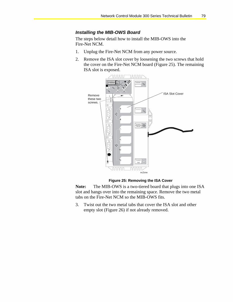
Network Control Module 300 Series Technical Bulletin 79
Installing the MIB-OWS Board The steps below detail how to install the MIB-OWS into the Fire-Net NCM.
1. Unplug the Fire-Net NCM from any power source.
2. Remove the ISA slot cover by loosening the two screws that hold the cover on the Fire-Net NCM board (Figure 25). The remaining ISA slot is exposed.
nc2srw
ISA Slot Cover
1 2 3 4 5 6 7 8
1 2 3 4 5 6 7 8
IN
OUT RELOAD7 8
POWER
ONCONFIG.
END OFLINE
A B
D-RAM
-ATTENTION -P L E A S E D I S C ON N E D T B A T T E R Y
B EFO R E IN S TA LLI NG ME MO R Y
BATTERY
N EX T S ER VI CE D ATE :R
EF
N2-
N2+
POWERSUPPLY
DISCONNECTPOWER BEFORE
SERVICING
DANGER
LIN E VOLTAGE
INSIDE
Removethese twoscrews.
A
B
ISASLOTS
I
II
IV
PORTS
III
Figure 25: Removing the ISA Cover Note: The MIB-OWS is a two-tiered board that plugs into one ISA slot and hangs over into the remaining space. Remove the two metal tabs on the Fire-Net NCM so the MIB-OWS fits.
3. Twist out the two metal tabs that cover the ISA slot and other empty slot (Figure 26) if not already removed.

Network Control Module 300 Series Technical Bulletin 80
Remove
Top View
Battery Power Supply
Fire-Net NCMBase
N1 LAN ARCNET Card
Twist Off
topview
Figure 26: Removing the ISA Tabs
Note: Because you now have easy access to the N1 ARCNET board, set the N1 network node address on the switches. Refer to the manual that came with the N1 ARCNET board for specifics on how to set the switches. Figure 27 shows an example of a node number within the required range for a Fire-Net NCM.
OPEN (or OFF)
1 2 3 4 5 6 7 8nn72
Figure 27: Network Node Address of 72

Network Control Module 300 Series Technical Bulletin 81
4. Make sure the MIB-OWS interrupt selector jumper is set to IRQ3 and plug the MIB-OWS board into the available ISA slot, fitting the ends into the ISA and empty slot.
5. Replace the two screws on the top of the ISA slot and empty slot and screw down.
6. Place the ISA slot cover back on and fasten with two screws.
Mounting Mount the Fire-Net NCM in either a Fire Watchdog Enclosure or a standard UPM enclosure. For information on mounting and wiring the Fire-Net NCM to the Fire Watchdog Enclosure, see Fire Watchdog Enclosure in the Application Details section of the Fire Operator Workstation (Fire OWS) Technical Bulletin (LIT-636014). If you are using a standard UPM, see the Design Considerations section of this document.
Wiring The MIFN works in conjunction with the Metasys N1 LAN to provide complete fire alarm, security alarm, and HVAC control. The Fire OWSs and Fire-Net NCMs are connected to both the MIFN and N1 LAN. The MIFN is the fire system communication path; however, if path resources are available on the N1 LAN, fire system communication may use the N1 LAN.
When the fire system requires commissioning and/or maintenance, communication uses the N1 LAN. In addition, the N1 LAN provides the interface between the fire alarm, energy management, and smoke control systems.
Media Options: N1 LAN For details on the N1 LAN media options, see the N1 ARCNET Local Area Network Technical Bulletin (LIT-636017).
Note: Use fiber-optic cable when connecting network nodes between buildings or, if you are using twisted pair, wire it in an underground conduit separate from all power wiring.
Media Options: MIFN Use twisted pair copper wire, fiber-optic cable, or a combination of the two to provide communication between the nodes of the MIFN. There are MIB-OWS models available with each of these cable options.
Note: To comply with UL Requirements, use fiber-optic cable when connecting fire network nodes between buildings or if you are using twisted pair, wire it in an underground conduit separate from all power wiring.
Network Control Module 300 Series Technical Bulletin 82
Making the N1 LAN Connection Follow the steps below to connect the Fire-Net NCM to the N1 LAN.
1. Install a T-connector into the port of the Fire-Net NCM N1 LAN ARCNET board.
2. Connect the N1 LAN cable to one end of the T-connector. If the NCM is at the end of line, connect a 93-ohm terminator cap to the other end of the T-connector. If the Fire-Net NCM is not at the end of line, connect the other segment of N1 LAN cable (that goes to the next N1 node) to the T-connector.
Refer to Figure 7 in the NCM Cable Guidelines, NCM N1 LAN Connection section of this document. If you have not set the Fire-Net NCM node number, see the Interface Boards, Installing the MIB-OWS Board section of this appendix for details.
Making the MIFN Connection: Copper Wire If you have not already installed the MIB-OWS board, see the Interface Boards, Installing the MIB-OWS Board section in this appendix to install it now. Once the board is installed, follow the steps below.
To make the MIFN connection using copper wire:
1. Install each end of the twisted pair wire into the terminal block of the MIB-OWS board, starting at the far left (Figure 28 and Figure 29).
Note: If the Fire-Net NCM is at the end of line, use the first two terminals from the left. If the Fire-Net NCM is not at the end of line, connect the twisted pair that goes to the next MIFN node into the next two terminals.

Network Control Module 300 Series Technical Bulletin 83
Top View
Battery Power Supply
Fire-Net NCMBase
N1 LAN ARCNET Boardtopview2
Use the last terminalfor an earth ground.
MIB-OWS-W-0
Figure 28: Orientation of the MIB-OWS Terminal Block
ncterm
Use the last terminalfor an earth ground.
Viewed above the Fire-Net NCM with
the connectorinstalled.
If the Fire-NET NCM is at theend of the line,use the firsttwo terminalsfrom the left toconnect to the FN.
Figure 29: Installing the Twisted Pair into the MIB-OWS Terminal Block 2. Earth ground the terminal block using the far right terminal
(Figure 28).

Network Control Module 300 Series Technical Bulletin 84
Making the MIFN Connection: Fiber-Optic Cable To install fiber optic cable into the MIB-OWS, use a cable terminated with an ST connector. The ST connector has a bayonet locking system connected using the steps below:
1. Line up the peg on the fiber optic cable connector with the slot on the top of the MIB-OWS receptacle (Figure 31).
2. Twist the spring-loaded fiber-optic cable collar to line up the slots with the two pegs on the receptacle.
3. Push the fiber-optic cable into the MIB-OWS receptacle and twist the spring collar so the receptacle pegs lock into place.
Top View
Battery Power Supply
Fire-Net NCMBoard
N1 LAN ARCNET Board fiber
MIB-OWS-F-0
Connect Fiber OpticCable Here
Figure 30: Fiber-Optic Cable Ports on MIB-OWS

Network Control Module 300 Series Technical Bulletin 85
fibercbl
Step 1: Line up the peg on the cable with the slot on the MIB-OWS.
Step 3: Push forward and twist to lock in place.
Push
Twist
MIB-OWS-F-0
Step 2: Twist the collar on the cable to line up with the peg on the MIB-OWS.
Collar
Peg
Twist
Figure 31: Connecting Fiber Optic Cable to MIB-OWS
Power Connection Plug the Fire-Net NCM into the power outlet at the top of either the Fire Watchdog Enclosure or the standard UPM. There are two screws and wire ties provided with the Fire-Net NCM to fasten the cord inside the enclosure or UPM. Run the cord along the right hand side of either enclosure and choose convenient locations to mount the ties.

Network Control Module 300 Series Technical Bulletin 86
G 0 8 5 S
ncmpwr
1 2 3 4 5 6 7 8
1 2 3 4 5 6 7 8
I N
O U T
R E L O A D7 8
P O WE R
O NC ON F IG .
E ND OFLIN E
a b
RE
FN
2-
N2
+
a
b
I SASL O TS
I
II
IV
C O M M -P O RT S
I II
PO WE RSU PP LY
D IS C ON N EC TP O WER BE FO R ES ER V IC I NG
DA N GE RLI NE VOLTAGE
IN S ID E
D - RA M
- AT TE NT I ON -PL EASE D
ISC ONN ED
T B ATTE RY
BEFOR E IN STA LLI NG MEMORY
BATTERY
NEXT SERVI CE D ATE:
Figure 32: Plugging the Power Cord into the Watchdog Enclosure For details on how to connect the Watchdog Enclosure to UPS power, see the Universal Packaging Module Technical Bulletin (LIT-6363070). The Watchdog Enclosure is an EN-EWC35.
Downloading a Fire-Net NCM Before you perform the download procedure on a Fire-Net NCM, make sure you follow the steps below:
1. Verify that the N1 LAN connection is good. NC code download data does not transfer over the MIFN. If you perform a download without the N1 LAN, the download fails and the Fire-Net NCM does not operate until a download is successful.
2. Verify that the MIFN connection is good. If you transfer data over the N1 LAN and the MIFN is offline, the fire system may not function properly.
Error Messages For information on error numbers that can occur with Fire-Net NCMs on the MIFN, see the Troubleshooting Guide (LIT-636328).
Some of the occurrences that cause errors are kept as counters in the MIFN Stats program. Refer to Metasys Intelligent Fire Network Technical Bulletin (LIT-448196), FN Stats Program section for details on how to diagnose the MIFN.

Network Control Module 300 Series Technical Bulletin 87
Order Numbers Table 29: Hardware Code Number Description NU-NCM300-FIRE/ NU-NCMFIRE-1
Metasys Fire-Net NCM with Power Supply
Choose from the following: MIB-OWS-F-0 MIB-OWS-WF-0 MIB-OWS-W-0
MIB Fiber Optic Transceiver MIB Fiber Optic/Copper Transceiver MIB Copper Wire Transceiver
NU-ARC101-0 Repair ARCNET Card. NU-BAT300-1 Replacement Battery for the Fire-Net NCM NU-NCM300-F700/ NU-NCMFIRE-701
Replacement Fire-Net NCM. Includes the same components as the NU-NCM300-FIRE.

Network Control Module 300 Series Technical Bulletin 88
Appendix B: NCM Maintenance Introduction
We recommend regular maintenance to help keep older NCMs from failing. Mission critical NCMs need the most attention. This section contains simple flowcharts, maintenance check procedures, and troubleshooting information to assist you in keeping NCMs running at peak performance.
NCM Maintenance Flowcharts Use the following flowcharts as guidelines for NCM maintenance.
Any MissionCricital NCMs
NoDone
Time for NCMMaintenance
Yes
No
NCM FieldInspection?
YesA
NCM PowerFail Test? B
Yes
No1
NCMDiagnostics
Defined
2 No
Yes
CYes
Done
No
Start
Figure 33: General NCM Maintenance Flowchart

Network Control Module 300 Series Technical Bulletin 89
A
RunningMetasys
Release 9.01Cor Later?
NCM Field Inspection
Yes
NCM 350Latest Flash
Installed?Download Flash
into NCM350No
Yes
NCM300Latest SIMM
InstalledOrder and Install
Latest SIMMs
Yes
No
Perform BatteryTest Bad Battery?
Yes ReplaceBattery
Yes
No
Doyou have a
battery tester?
No
Yes
No
No
Inspect PowerSupply?
Yes Bad PowerSupply
Yes Replace PowerSupply
1
No No
Order BatteryTester
PerformBattery Test?
Figure 34: NCM Field Inspection Flowchart

Network Control Module 300 Series Technical Bulletin 90
B
Clear NCM ErrorLog
NCM Power Fail Test
Perform NCMPower Fail Test
Collect Error LogData
NCMRecover?
FlashingLED 7?
NoReplace Battery
Yes
Bad PowerSupply
No
Yes
2
Replace PowerSupply
No
Yes
Yes
Figure 35: NCM Power Fail Test Flowchart

Network Control Module 300 Series Technical Bulletin 91
CNCM Diagnostics
MetasysRelease 9.01 orLater Installed?
NoReturn
Data Collected Map AD Objects toNCM Diagnostics
No
Idle Time >70%?
Take CorrectiveAction
AcquiredMemory
Depleted?
Take CorrectiveAction
JCB TIME >12%
Take CorrectiveAction
Return
Yes
Yes
Yes
Yes
Yes
No
No
No
Figure 36: NCM Diagnostics Flowchart

Network Control Module 300 Series Technical Bulletin 92
Maintenance Quick Check Follow this quick checklist to help maintain NCMs:
All NCMs running Metasys Release 9.01C or later
All NCM350s running latest flash
All NCM300s have latest SIMMs installed
Battery test completed
Power supply inspected, all NCM types (replaced NU-PWR101-0 and NU-PWR101-700)
NCM Power Fail test completed
NCM Performance Diagnostics defined (optional)
Field Inspection Scheduled visits to the NCM location are required as part of the total NCM Maintenance program. The following table shows operations required while inspecting an NCM.
Table 30: Field Inspection Inspection Type NCM Battery Power Supply Visual Touch Smell SIMM Version
(NCM300)
Battery Test Power Fail Test
System Inspection On jobs running older Metasys software, inspect NCM systems for all problems listed in this section.
NCM System Problems Fixed with Metasys Software, Release 9.01 or Later NCM Reboots - Some Metasys ARCNET jobs experience random NCM reboots. The symptoms indicate a repeating series of messages in the NCM error log file culminating in a reboot due to lack of acquired memory. Metasys Release 9.01 or later eliminates this problem without replacing all the Thomas-Conrad ARCNET cards with CCSI cards.

Network Control Module 300 Series Technical Bulletin 93
Running Metasys Database Programs with an Active PMI - Serious ARCNET N1 network corruption can occur if Windows 95 or Windows 98 operating systems configures the PC hardware. Windows 95 and Windows 98 operating systems include an additional ARCNET driver that becomes active with a Metasys DOS database application such as UNDDL. Metasys Release 9.01 or later prevents the NCM from crashing if this situation occurs. Make sure the Windows 95 or Windows 98 operating systems provided ARCNET driver is not present on the OWS.
NCM NOVRAM Mirroring - After reviewing NCM problems encountered at customer sites, we enhanced the reliability of NCMs during power cycles. Changes were made in both EPROM and flash downloads. A CRC (checksum) is now implemented on NOVRAM and DRAM.
If the NOVRAM CRC passes during power up, the NCM powers up normally. If the NOVRAM CRC fails power up, the DRAM is CRC checked. If correct, the DRAM is copied to NOVRAM and the NCM boots up normally. If both the NOVRAM and DRAM fail CRC checks, the factory default settings are written to NOVRAM and the NCM does not boot.
All new NCM350s shipped starting August 1, 1998 have the mirroring built in. Metasys Release 9.01 or later is required to gain the full benefit of mirroring.
Upgrade all mission-critical NCM300s previously installed by ordering and replacing the on-board SIMM module. Metasys Release 9.01 or later is required to gain the full benefit of mirroring. Upgrade all critical NCM350s by installing Metasys Release 9.01 or later and perform the flash download using NCSETUP. No hardware upgrade is required.
NCM Diagnostics Metasys Release 9.01 or later allows the mapping of Analog Data (AD) software objects to NCM operating system attributes. Table 31 shows the reserved attributes are entered in the associated hardware attribute field. The Associated System/Object fields are left blank. The reserved word attributes are:

Network Control Module 300 Series Technical Bulletin 94
Table 31: Hardware Attribute Values Value Description IDLE This number represents the exponential weighted average of the NCM CPU idle time. A
value of 70% and higher yields the best performance. FREEMEM This is the Acquired Memory parameter. This value fluctuates over time but should never
gradually go to zero. N1RX This value represents the received message rate per minute. N1TX This value represents the transmitted message rate per minute. JCBTIME This value is the % Central Processing Unit (CPU) time used running the JCB Interpreter, a
measure of amount of GPL processes running. A value greater than 10% is considered excessive.
N1RXERR This value displays the counter for discarded corrupted N1 ARCNET messages. The counter is reset on download.
IPRXERR This value displays the counter for N1 Ethernet messages. The counter is reset on download. STBYSTAT This number represents the status of the Standby NCM. 1 = responding; 2 = not responding. N2APPS This NCM diagnostic data value displays the polls per second for the first N2 trunk supported
by the NCM. This diagnostic is supported at Metasys Release 10.01 and later. N2ACPS This NCM diagnostic data value displays the commands per second for the first N2 trunk
supported by the NCM. This diagnostic is supported at Metasys Release 10.01 and later. N2BPPS This NCM diagnostic data value displays the polls per second for the second N2 trunk
supported by the NCM. This diagnostic is supported at Metasys Release 10.01 and later. N2BCPS This NCM diagnostic data value displays the commands per second for the second N2 trunk
supported by the NCM. This diagnostic is supported at Metasys Release 10.01 and later.
These values can be alarmed and trended. DDL, UNDDL, and GPL support these AD objects.
NCM Inspection Perform the following inspections to help determine if the unit is able to continue operating at peak performance:
NCM – SIMM – NCM300s - Inspect the SIMM boards to ensure they are still securely fastened in the sockets. It is possible that they are not completely seated.
Metasys Release 9.01 and later performs NOVRAM mirroring, which prevents NOVRAM corruption during a Power Fail. Order and install NCM300 SIMM Version 6.02, part number NU-ROM101-1 to take full advantage of the NOVRAM mirroring feature.
If the NCM is to be powered down for power supply inspection, the SIMM boards may be considered for connector/socket cleaning. To clean SIMM edge connectors, use contact cleaning wipes. Do not use erasers to clean edge connectors.
NCM – Power Fail Test - Test ability to recover from power failures by following the procedure described in the NCM Power Fail Test section of this document.

Network Control Module 300 Series Technical Bulletin 95
NCM Battery Visual Inspection Refer to Figure 37 for battery and power supply location.
nc3power
Battery Cover
Power Supply Mounting Screw
Power Cord to Main AC .
Power Supply
Power conditioning board isunder sheet metal at this end.
ISA Slot Cover
1 2 3 4 5 6 7 8
1 2 3 4 5 6 7 8
IN
OUT RELOAD7 8
POWER
ONCONFIG.
END OFLINE
a b
D-RAM
-ATTENTION -PLEASE DI SCONNEDT BATTERY
BEFORE INSTALLING MEMO RY
BATTERY
NEXT SERVICE DATE:
RE
F
N2-
N2+
a
b
ISASLOTS
I
II
IV
COMM-PORTS
III
POWERSUPPLY
DISCONNECTPOWER BEFORE
SERVICING
DANGER
LINE VOLTAGE
INSIDE
Battery Fault(LED)
Figure 37: NCM Battery and Power Supply
NCM Battery Status When the battery status LED is off, the battery and battery charging circuit are operating properly. You can check on the battery status in three ways:
• Light-Emitting Diode (LED) indicator
• NCM Diagnostics (“NCM Misc Data”) from Network map
• NCSETUP for Windows or, NCSETUP (DOS version, choose the Read NC Type option [good, bad, not installed])
Notes: The LED may light for several seconds when a discharged battery has been installed. If this condition persists for more than one minute, replace the battery.
The Battery Fault LED indicates whether a battery is installed. It does not indicate the charge level or operational status of the battery.
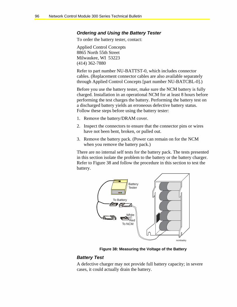
Network Control Module 300 Series Technical Bulletin 96
Ordering and Using the Battery Tester To order the battery tester, contact:
Applied Control Concepts 8865 North 55th Street Milwaukee, WI 53223 (414) 362-7880
Refer to part number NU-BATTST-0, which includes connector cables. (Replacement connector cables are also available separately through Applied Control Concepts [part number NU-BATCBL-0].)
Before you use the battery tester, make sure the NCM battery is fully charged. Installation in an operational NCM for at least 8 hours before performing the test charges the battery. Performing the battery test on a discharged battery yields an erroneous defective battery status. Follow these steps before using the battery tester:
1. Remove the battery/DRAM cover.
2. Inspect the connectors to ensure that the connector pins or wires have not been bent, broken, or pulled out.
3. Remove the battery pack. (Power can remain on for the NCM when you remove the battery pack.)
There are no internal self tests for the battery pack. The tests presented in this section isolate the problem to the battery or the battery charger. Refer to Figure 38 and follow the procedure in this section to test the battery.
ncmbattry
To Battery
To NCM
White
Red
BatteryTester
Figure 38: Measuring the Voltage of the Battery
Battery Test A defective charger may not provide full battery capacity; in severe cases, it could actually drain the battery.

Network Control Module 300 Series Technical Bulletin 97
Follow these steps to perform a test of the charger and battery:
1. Open the battery case and disconnect the battery from the charger.
2. Connect the tester to the battery charger cable.
- If charger voltage is above 6.0 VDC, the charger is working properly and the green LED illuminates.
- If charger voltage is above 8.0 VDC, the charger is producing excessive voltage and the yellow LED flashes.
3. Connect the tester to the battery.
4. Wait 30 seconds for the tester to sense the battery voltage.
5. Stop the battery test if the battery has less than 5.5 VDC, and the red LED illuminates.
6. Begin the battery load test if the battery voltage is above 5.5 VDC. The yellow LED illuminates when the test is in progress.
7. Wait 30 minutes with the load connected to the battery while continuing to monitor the battery voltage. If the battery voltage ever drops below 5.5 VDC, the red LED flashes and you should stop the test. If after 30 minutes the battery is still above 5.5 VDC, the green LED flashes, which means the battery is good.
! CAUTION: Risk of Personal Injury. Avoid contact with the outer surface of the battery tester. The battery tester becomes hot to the touch during testing and could cause a burn upon contact.
The green, yellow, and red LEDs on the battery tester show the status of the test the charger is performing. Table 32 summarizes the different LED color combinations and what each combination indicates regarding the test.
Table 32: LED Summary Indication Green LED Yellow LED Red LED Circuit Test when Power is First Applied (This repeats when battery is connected first.)
On On On
Charger Defective Off Off Off Charger Operational On Off Off Charger Voltage Excessive On Flashing Off No Battery Connect or Shorted Battery On Off On Battery Test in Progress On On Off Defective Battery On Off Flashing Test Complete, Battery and Charger Operational Flashing Off Off
Network Control Module 300 Series Technical Bulletin 98
Replacing the Battery Pack To replace the battery pack:
1. Remove the battery/Dynamic Random Access Memory (DRAM) cover.
2. Disconnect the battery and firmly pull on the battery cable. (This dislodges the battery pack from the cover.)
3. Place the new battery pack in the cover so that the fastener material is aligned.
4. Press the battery pack down firmly.
5. Reconnect the cable and press the battery connector against the small patch of fastener material on the side of the cover.
6. Replace the cover.
The battery pack (Figure 1: Callout 11) is secured to a cover and fits over the SIMMs. It automatically recharges from the NCM and maintains the operating system and databases in RAM for up to a 72-hour power failure. (See Table 6 for backup times according to memory configuration.)
The NCM arrives from the factory with the battery pack unconnected. Connect the battery last when installing the NCM.
Battery Power Fail Test Refer to the NCM Maintenance Flowcharts section of this document for instructions on performing the battery Power Fail test.
Test for Recoverability A critical aspect of a Metasys network is for NCMs to recover from expected or unexpected Power Fail. A significant aspect of NCM maintenance is to perform routine Power Fail tests. There are certain conditions, which prevent NCMs from recovering from a Power Fail. Bad batteries can cause a DRAM memory parity error during the power up portion of a Power Fail. Also, if a job has not been retrofitted with the latest SIMM (NCM300) or flash code, a Power Fail can cause NOVRAM corruption on power up.
Routine Power Fails could possibly catch the power up problem prior to experiencing an actual Power Fail and causing the NCM to be nonfunctioning.
Use the Power Fail Test Worksheet (PFTWS) to test each NCM for recoverability.

Network Control Module 300 Series Technical Bulletin 99
Power Fail Test Worksheet (PFTWS) Complete the worksheet in Figure 39 for each NCM. Note that the NCM error log must be cleared prior to each series of tests. Make copies of the worksheet as necessary.
NCM NCM Error Log
Good Battery Connected Bad Battery (or non-Connected)
NCM ______ NCM Type ____________
[ ] Clear – good battery [ ] Clear – bad battery
Verify Battery Connected Check Battery Fault Light Status (Off/On)_____ Remove Main Power Reconnect Main Power
Verify Battery Not Connected Check Battery Fault Light Status (Off/On)_____ Remove Main Power Reconnect Main Power
Record Contents of NCM Error Log Record Contents of NCM Error Log
[ ]__________________________ _____________________ [ ]__________________________ _____________________ [ ]__________________________ _____________________ [ ]__________________________ _____________________ [ ]__________________________ _____________________ Record Time to completely return online ________minutes
[ ]__________________________ _____________________ [ ]__________________________ _____________________ [ ]__________________________ _____________________ [ ]__________________________ _____________________ [ ]__________________________ _____________________ Record Time to completely return online ________minutes
Perform Software Reset (optional) Perform Software Reset (optional) NCM ______ NCM Type _______________
Clear Verify Battery Connected Check Battery Fault Light Status (Off/On)_____ Perform Software Reset
Verify Battery Connected Check Battery Fault Light Status (Off/On)_____ Perform Software Reset
Record Contents of NCM Error Log Record Contents of NCM Error Log
[ ]_______________________ ______________________ [ ]_______________________ ______________________ [ ]_______________________ ______________________ [ ]_______________________ ______________________ [ ]_______________________ ______________________ Record Time to completely return online_____minutes
[ ]________________________ _______________________ [ ]________________________ _______________________ [ ]________________________ _______________________ [ ]________________________ _______________________ [ ]________________________ _______________________ Record Time to completely return online _____minutes
Figure 39: Power Fail Test Worksheet Table 33 shows the expected results of having performed the Power Fail tests, using the PFTWS form. The notes in Table 33 offer an analysis of the test results. If the respective NCM’s error logs do not show the listed sequence for the 181 entry, other problems are present.

Network Control Module 300 Series Technical Bulletin 100
Table 33: Power Fail Test Results Model NCM300-1 -2 NCM30
0 Notes NCM350-1 -2 -8 NCM350
Notes Memory EPROM / SIMM 6.00 (-1)
EPROM / SIMM 6.02 (-2) 1 FLASH 8.01
SIMM 8.02 1
Battery Status (LED)
Not Installed – LED on Good–LED – off Bad–LED on
2 Not Installed – LED on Good – LED – off Bad – LED on
2
Power Fail (Good Battery)
181 2 Power Fail** 3 181 2 Power Fail** 4
Power Fail (Bad Battery)
181 0 Coldstart* 181 1 Warmstart*
5 181 0 Coldstart* 181 1 Warmstart*
6
Power Fail (No Battery)
181 0 Coldstart* 181 1 Warmstart*
7 181 0 Coldstart* 181 1 Warmstart*
8
Software Reset
181 3 Software Reset*
9 181 3 Software Reset* 10
DRAM (Battery Backed)
Expand to 10 MBs using SIMMs 2,4,6,10
Expand to 10 MBs using SIMMs 2,4,6,10 Since 12/98: NCM350-8:
Notes: * Error log entries in the NCM error log ** New error log entries for Metasys Release 11.00 1. Verify latest EPROM revision. 2. Check the same data used by NCSETUP: good, bad, or missing. If the LED is lit, the battery is missing.
Verify using WNCSETUP information. 3. NCM300: power fail sequence: 181 2–means Power Fail with good battery, check battery status. After a
Power Fail, the NCM error log should contain the entry listed above. Other entries must be analyzed. 4. NCM350: Power Fail sequence: 181 2–means Power Fail with good battery, check battery status. After a
Power Fail, the NCM error log should contain the entry listed above. Other entries must be analyzed. 5. NCM300: Power Fail sequence: 181 0, 181 1–means Power Fail with bad or missing battery, check
battery status. After a Power Fail, the NCM error log should contain the sequence listed above. The 0 entry indicates a request for ‘data’ download because the DRAM is determined to be bad. Other entries must be analyzed.
6. NCM350: Power Fail sequence: 181 0, 181 1–means Power Fail with bad or missing battery, check battery status. After a Power Fail, the NCM error log should contain the sequence listed above. The 0 entry indicates a request for ‘data’ download because the DRAM is determined to be bad. Other entries must be analyzed.
7. NCM300: Power Fail sequence: 181 0, 181 1–means Power Fail with bad or missing battery, check battery status. After a Power Fail, the NCM error log should contain the sequence listed above. The 0 entry indicates a request for data download because the DRAM is determined to be bad. Other entries must be analyzed.
8. NCM350: Power Fail sequence: 181 0, 181 1–means Power Fail with bad or missing battery, check battery status. After a Power Fail, the NCM error log should contain the sequence listed above. The 0 entry indicates a request for data download because the DRAM is determined to be bad. Other entries must be analyzed.
9. NCM300, manual reset: 181 3–After a manual reset, the NCM error log should contain the sequence listed above. The 3 entry indicates a manual reset.
10. NCM350, manual reset: 181 3–After a manual reset, the NCM error log should contain the sequence listed above. The 3 entry indicates a manual reset.

Network Control Module 300 Series Technical Bulletin 101
Power Supply (NCM3XX) Periodic inspection is required to ensure the NCM power supplies are performing at their peak. This section describes routine power supply inspection.
Remove the power supply cover to complete the inspection. Replace the power supply if any of the following conditions are detected:
• Power Supply Visual Inspection - The Metal Oxide Varistors (MOVs) are discolored. The MOVs
are the power line transient suppressors (located on the power conditioning board) - large red discs about the size of a nickel. If the MOVs are discolored and not bright red, the supply must be replaced. If the MOVs are discolored, future transient suppression may not happen.
- The power supply printed wiring board has any discoloration spots or brown areas.
• Power Supply Touch The power supply should be cool/warm to the touch.
• Power Supply Smell Replace the power supply if it smells burnt.
Determining the Status of the Power Supply This procedure is optional. It can help determine whether the power supply is defective.
! IMPORTANT: When probing the ISA slots, avoid short circuiting the power pins to the adjacent ISA pins (3, 5, 7, and 9). Short circuiting the pins may damage the main board.
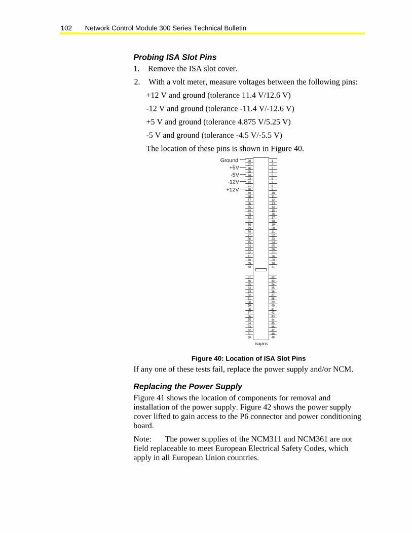
Network Control Module 300 Series Technical Bulletin 102
Probing ISA Slot Pins 1. Remove the ISA slot cover.
2. With a volt meter, measure voltages between the following pins:
+12 V and ground (tolerance 11.4 V/12.6 V)
-12 V and ground (tolerance -11.4 V/-12.6 V)
+5 V and ground (tolerance 4.875 V/5.25 V)
-5 V and ground (tolerance -4.5 V/-5.5 V)
The location of these pins is shown in Figure 40. 98979695949392919089888786858483828180797877767574737271706968
12345678910111213141516171819202122232425262728293031
676665646362616059585756555453525150
323334353637383940414243444546474849
Ground+5V-5V
-12V+12V
isapins
Figure 40: Location of ISA Slot Pins If any one of these tests fail, replace the power supply and/or NCM.
Replacing the Power Supply Figure 41 shows the location of components for removal and installation of the power supply. Figure 42 shows the power supply cover lifted to gain access to the P6 connector and power conditioning board.
Note: The power supplies of the NCM311 and NCM361 are not field replaceable to meet European Electrical Safety Codes, which apply in all European Union countries.

Network Control Module 300 Series Technical Bulletin 103
nc3power
Battery Cover
Power Supply Mounting Screw
Power Cord to Main AC .
Power Supply
Power conditioning board isunder sheet metal at this end.
ISA Slot Cover
1 2 3 4 5 6 7 8
1 2 3 4 5 6 7 8
IN
OUT RELOAD7 8
POWER
ONCONFIG.
END OFLINE
a b
D-RAM
-ATTENTION -PLEASE DI SCONNEDT BATTERY
BEFORE INSTALLING MEMO RY
BATTERY
NEXT SERVICE DATE:
RE
F
N2-
N2+
a
b
ISASLOTS
I
II
IV
COMM-PORTS
III
POWERSUPPLY
DISCONNECTPOWER BEFORE
SERVICING
DANGER
LINE VOLTAGE
INSIDE
Battery Fault(LED)
Figure 41: Location of Power Supply Components
Removal of Power Supply It may be easier to remove the power supply when the ISA slot cover is removed.
To remove the power supply:
1. Turn off main AC power.
2. Disconnect the NCM AC cord from the power box (not from the NCM end).
3. Remove the power supply mounting screw from the NCM base.
4. Slide the power supply assembly down (away from the battery cover) approximately 1/4 inch to disengage it from the NCM base.
5. Lift power supply up approximately one inch to gain access to the power conditioning board. See Figure 42.
6. Disconnect the power conditioning board from the P6 connector on the NCM board by pulling up firmly on its outer edges.

Network Control Module 300 Series Technical Bulletin 104
1 2 3 4 5 6 7 8
1 2 3 4 5 6 7 8
IN
OUT7 8
POWER
CONFIG.
END OFLINE
D-RAM
-ATTENTION -P L E A S E D IS C ON N E D T B A T T E R Y
BEFORE INSTALLING MEMORY
BATTERY
NEXT SERVICE DATE:a
b
ISASLOTS
I
II
IV
COMM-PORTS
III
POWERSUPPLY
DISCONNECTPOWER BEFORE
SERVICING
DANGER
LINE VOLTAGE
INSIDE
Remove screw,slide down.
Lift Up
p6conctr
BATT ERY
NEXT SERVICE DATE:
Power
P6Connector
PowerConditioning
Board
Figure 42: P6 Connector and Power Conditioning Board
Installation of Power Supply To install the power supply:
1. Connect the power conditioning board to the P6 connector on the NCM board. See Figure 42.
2. Line up the power supply sheet metal in slots in the NCM base sheet metal and engage by sliding up toward the battery cover.
Note: Be careful not to pinch any wires.
3. Install the power supply mounting screw.
4. Reconnect the AC cord to the power box.
5. Turn on main AC.

Network Control Module 300 Series Technical Bulletin 105
Appendix C: NCM100 Power Supply Troubleshooting Introduction
Some NU-PWR101-0 power supplies shipped prior to the end of 1995 experience random failures that become evident only after cycling the line power. After restoring line power, the power supply is dead with no output. The problem is due to component aging, and the likelihood of its occurring increases with time. Older power supplies operating at high ambient temperatures aggravate the problem.
These power supplies may fail one at a time in a seemingly random pattern, or they may fail in large numbers, all at once, particularly after events such as building power outage or standby power testing. Note that these power supply failures are a function of component aging and will likely occur after many years (7-10) of service.
Products Affected Some NU-PWR101-0 and NU-PWR101-700 power supplies (at Revision A through F) are affected. These power supplies have a manufacturing date code 9522 or earlier. The power supply at Revision G or later, regardless of date code, is redesigned to further extend the life.
The revision level of installed boards can be verified only by powering down the NU-PWR101 and examining the label on the side of the assembly. Make sure a replacement NU-PWR101 is readily available in case of failure during verification of the revision level.
Recommended Action You and your customers should assess the risk and plan appropriate action. It is important to address those customers who have mission critical jobs or a large number of affected NU-PWR101 power supplies. Strongly encourage those customers to take preventive action to minimize the possibility of a disruption to the operation of their systems.

Network Control Module 300 Series Technical Bulletin 106
Preventive Action Consider job site expansion and maintenance strategy and the options suggested below to decide what update or upgrade plans might best fit this customer’s overall operation.
Consider the following risks and options for your customers:
• Advise the customer of a potential problem when line power is cycled to the NU-PWR101 power supply. We are dedicated to maintaining a good customer relationship and are proactive in notifying customers of the potential for a problem. Early notification allows the customer to budget for preventive measures and to implement them in an organized manner.
• Caution the customer to avoid cycling line power to a large number of units simultaneously as is done during standby power testing.
SolutionSuggest updating the existing NU-PWR101 power supplies to NU-PWR101-7MNT power supplies. The Repair and Return procedure is an effective and inexpensive method to address this situation.
The Repair Center schedules a swap and upgrade timetable for the units on your job based on availability of ship-ahead power supplies to get your swapout started.
The success of this program depends on installing these updated units according to the schedule and returning the replaced units immediately.
The Repair and Return procedure is as follows:
1. Place a separate order for each job requiring replacement NU-PWR101-7MNT. Only replacements ordered by the NU-PWR101-7MNT code number are available at this lower price option. You are billed at full price and a credit is issued upon return of the replaced units.
2. Specify the total quantity of power supplies required for the job.
3. Specify the want date or dock date for shipment. This makes it easy to schedule multiple shipments as determined during the initial call to the Repair Center. No other items can be on the same order. Identify all the jobs requiring attention, and schedule replacement at a reasonable rate and timetable to allow the Repair Center to plan the resources needed to meet the requirements.
Network Control Module 300 Series Technical Bulletin 107
4. Receive and replace units. When replacing, verify that the revision level on the label on the side of the original unit is prior to Revision G.
5. Return the replaced units to the Repair Center on a regular RMA. The RMA is used to track returns, collect failure data, and issue credit.
6. Send a completed RMA with each shipment containing the information listed in Steps 8-11.
7. The Branch Number, Name, Job name, Originator, and Credit To Account are the same as the original factory order.
8. In the Reason for Return section, check the Trade-in box.
9. In the Quote Authorization section, enter PWR101 Maintenance Program.
10. Enter the Quantity shipped (use Code Number NU-PWR101-7MNT) for the item being returned.
11. Include this RMA with the return shipment to expedite your credit and handling. Keep a copy for your records.
You can find additional instructions for completing a Return Material Authorization (RMA) Form 11014.
The success of this program is, in a large part, dependent on your ability to quickly replace and return the affected power supplies. The returned units are updated and sent back to you; the faster you respond, the quicker the job is completed. Complete the replacement in a timely manner to minimize the number of power supplies in the branch waiting for installation or in transit.
Inform the customer that scheduled preventive action helps avoid unexpected problems and results in lowest overall cost, along with significant increased system reliability and peace of mind. These units have provided years of service and failure to take appropriate action could impact the long-term reliability of the system.
Controls Group 507 E. Michigan Street P.O. Box 423 www.johnsoncontrols.comMilwaukee, WI 53201 Published in U.S.A.