netvu observer user guide - dedicatedmicros-support.com · dedicated micros netvu observer video...
TRANSCRIPT

NetVu ObserVerUser Guide

Dedicated Micros ©20112
Net
Vu O
bser
Ver
Contents
Introduction ....................................................... 3
Installing NetVu ObserVer Software ................. 6
Configuring NetVu ObserVer Software ............. 7
NetVu ObserVer Controls................................ 21
Alarm Receiving Functionality ......................... 43
EDP Report Generator .................................... 51
Additional Functionality ................................... 57
Appendix A ...................................................... 63
Appendix B ...................................................... 64
Notes ............................................................... 66
Index ............................................................... 67

Dedicated Micros ©2011 3
Net
Vu O
bser
Ver
IntroductionDedicated Micros NetVu ObserVer video management software allows users to seamlessly view distributed images from any “NetVu Connected” product, such as SD Advanced, EcoSense, CamVu IP Cameras or the DV-IP Range.
MULTIPLE SITE MANAGEMENT
Its site tree facility allows servers and individual cameras to be accessed quickly, and the inclusion to view multiple sites simultaneously makes the management of any CCTV installation more efficient and responses to events even quicker.
RVRC SUPPORT
NetVu ObserVer also includes features that make it capable of supporting RVRC (Remote Video Response Centre) operation. These include auto event distribution to multiple user stations, event closure characterisation, session management to enable multiple events from a single site to be handled as a single alarm session, and report generation capabilities to enable both billing and maintenance management.
SIMULTANEOUS VIEWING STREAMS
Built-in MPEG-4 support provides simultaneous viewing of both JPEG and MPEG-4 video streams, allowing the user to optimise bandwidth usage on constrained networks. A straight forward drag and drop GUI, together with saved screen views provide the user with an easy to use viewing solution, offering a seamless single user interface to all NetVu Connected products.
NetVu ObserVer is available as a download from the Dedicated Micros website and is included with all NetVu Connected products. Visit http://www.dedicatedmicros.com/uk/netVu_observer or contact customer services in your region for more information.
■ Controls all NetVu Connected video servers and devices■ Multiscreen layouts in both 4:3 and 16:9 formats■ Export video to AVI and MPEG-2 formats■ Simple drag and drop selection of cameras■ Automatic detection and switching between MultiMode MPEG-4 / JPEG live and
playback streams■ Saveable views made up of multiple sites■ Incident Finder to simplify the process of finding incident related video■ On-screen map display for quick selection of sites and cameras■ Control of remote functions including bidirectional audio and telemetry■ Reference images assignable to specific cameras■ Telemetry control, including PTZ and telemetry presets■ Text display allows information from systems such as POS and ATM machines to be
viewed, in association with captured video, via a dedicated window■ Google Earth integration for TransVu applications■ Create PDF reports with images, data and comments
ENGLISH
Whilst every attempt is made to ensure these manuals are accurate and current, Dedicated Micros reserve the right to alter or modify the specification described herein without prejudice.
NO V1.18.27 JV 1.6.0_23

Dedicated Micros ©20114
Net
Vu O
bser
Ver
Features and FunctionsNetVu ObserVer software is a dedicated application that offers single-site and multi-site control allowing an Operator to simultaneously monitor and control video from one image server or from several distributed sites.
The single-site functionality allows multiple cameras from the same image server to be viewed, in a multiscreen format, in Live or playback mode. This ensures the Operator is aware of all potential events that may occur within the ‘site’ they are responsible for monitoring. This functionality can be compared to an installation using analogue monitors and a keyboard but with the advantage of locating the monitoring station anywhere on the network, therefore removing the limitations of a conventional wired system, i.e. maximum distances.
The software includes the necessary control functions for monitoring a video surveillance system for controlling PTZ cameras, establishing audio connections, camera switching, etc. It also allows a set of cameras to be saved as a display preset. These presets can then be programmed to sequence automatically at a pre-programmed time interval.
To enhance NetVu ObserVer software, additional functionality includes multi-site monitoring capabilities. This is an ideal feature for central monitoring stations where video from multiple sites is routed across a network connection to a centralised location. This provides for Live and Recorded images from numerous sites (up to thirty-six) that can be viewed and controlled at a single location.
The software provides all the necessary controls required for a Central Monitoring application and with the introduction of ‘drag and drop’, the application now becomes even more intuitive, allowing Operators to access cameras with a single key command.
Each event that comes in from a site opens an alarm session, if subsequent events come in from that site before it is closed they join that session. Sessions are automatically served to operators logged into the Event Distribution Point. Operators can view replay and live images from the site quickly to be able to respond to activities on the site. All the events are logged in an SQL database, and video from each session is linked to the alarm log, providing a clear audit trail.
Users are then required to close and characterise the events prior to closing the session, thereby enabling a compliant BS8418 audit trail.
Reports from the database can be created using standard database tools to enable bespoke solutions for customer management.
NetVu ObserVer enables access to the event lists that are stored on the image server. These files are where all logged alarms, VMD incidents and system changes are stored allowing the Operator quick and easy access to any event video recordings that are saved on the image server.
The following diagram shows how NetVu ObserVer software can be integrated in a Central Monitoring system, with access and control to any of the image servers that are part of the NetVu Connected product range.
Dedicated Micros has also taken the complete system integration one step further to allow new and existing systems to be monitored from a central monitoring station. NetVu ObserVer supports the ability to view and control the following Dedicated Micros products:
Note: The functionality available to the Operator will vary depending on which of the above (NetVu Connected or existing) is being controlled, refer to the Operational Controls section of this manual for details.

Dedicated Micros ©2011 5
Net
Vu O
bser
Ver
• NetVu Connected Video Servers, cameras and DVR’s.• Existing DVR’s with upgraded software for CGI support, inc Eco, DS2A, DS2P, BX2
The image servers and DVR’s support the necessary network protocols to allow NetVu ObserVer to be the Operator interface for any installation using the above DM products.
How this Manual is ConstructedThe Manual is divided into five sections:
• Installing NetVu ObserVer software• Configuration of the application (customising the installed viewer)• Operational controls• Alarm Receiving Functionality• Additional functionality
Acronyms used in this document:• EDP Event Distribution Point• RVRC Remote Video Response Centre• DVR Digital Video Recorder• ARC Alarm Receiving Centre
ENGLISH
NetVu ObserVer software can be accessed from:• Directly off the CD ROM supplied with the unit• Downloaded from the Dedicated Micros website (www.dedicatedmicros.com)• Downloaded from the unit via the webpage menus
ENGLISH

Dedicated Micros ©20116
Net
Vu O
bser
Ver
Installing NetVu ObserVer SoftwareNetVu ObserVer software is supplied on CD with the NetVu Connected device or alternatively can be downloaded from Dedicated Micros website.
The installation process described here works with either of these options.
Note: It is necessary to install the appropriate JRE file for the PC operating system the software is to be installed on. The JRE files can be found on the supplied CD ROM. If this file is not installed the application will not work.
PC Specifications
Minimum RecommendedOperating System Window XP Pro Windows XP ProProcessor 1GHz Intel Pentium 3 2GHz Intel Pentium 4 or equivalent or equivalentSystem RAM 512MB 1024MBScreen Resolution 800 x 600* 1024 x 768 or higher*Colour Depth 24bit* 24bit or 32bit*
ENGLISH
Installing the JRE (Java runtime environment) file1. Find the JRE file on the CD. The latest JRE is also available from java.com.2. Run the exe file.3. Use the installation wizard and follow the screen prompts to install the file.4. Once the JRE file has been installed NetVu ObserVer can be installed.
ENGLISH
Installing NetVu ObserVer application1. Find the exe file from either the CD or the web download. The software can also be
downloaded from a Dedicated Micros DVR or camera, by clicking the download link on the splash page.
2. Run the exe file.3. Using the installation wizard follow the on screen prompts.4. Select ‘Next’.5. You may enter an install location or use the default setting. Selecting browse will allow
you to search the drives available to you on your PC and the network.6. Select ‘Next’ and the software installation process will commence.7. Select ‘Finish’ to end the installation process. A short cut to launch DM NetVu ObserVer
will be automatically created on your desktop (unless this is disabled). The software can also be launched from Start -> Programs -> DM NetVu ObserVer.
8. Select ‘Close’ to complete the file installation.9. You will now be able to launch NetVu ObserVer application from the Start option or via
the shortcut on the desktop.Note: If you are replacing a version of NetVu ObserVer earlier than 1.9.xx, the installation
procedure may leave some artefacts from the older installation including desktop links to the old exe. If this happens, call Technical Support in your region for advice on removing the old file.
ENGLISH

Dedicated Micros ©2011 7
Net
Vu O
bser
Ver
Configuring NetVu ObserVer SoftwareEach install of NetVu ObserVer software can be configured to provide ‘customisation’ for specific Operator workstations.
This section details the settings that can be configured for each install of the ObserVer application. This includes; the behaviour and appearance of the application and configuration options for each image server accessible by the Operator.
Tools MenuThe Tools option provides access to configuration screens for the behaviour and appearance of the application.
Select Tools -> Options, the following configuration screen will be displayed.ENGLISH
BehaviourThis determines how the application will function, network settings and how the database will store and display information.
Set Image Server Tree Options Cameras within NetVu ObserVer are selected via a site tree folder; This option allows previously configured sites to be selected.
Set Event Database Options The image servers store specific events within a database, NetVu ObserVer can access the event database of the unit it is connected to. This option enables the operation of this feature to be configured and determines how the application will function when selecting an event i.e. pause the video. Note: This is not the RVRC database.
Set number of Events per pageControls how many events are displayed when the event button is clicked, selectable between 10-100, default: 30.

Dedicated Micros ©20118
Net
Vu O
bser
Ver
Set Event Pre-Alarm Time (in seconds) Controls the amount of time prior to an event is played when an
event is played back from the event list, selectable between 0-120 seconds, default: 0 seconds.
Set Event Search Timeout (in Seconds) Controls how long the remote server is given to return the event
list before being stopped. Selectable between 0-60 seconds, default: 10 seconds. If the number of events per page is a large number, this value should be increased.
Choose action to be taken on Event Selection Determines what ObserVer will do with the video data when an
Event is selected. The options are Play, Pause, Fast Forward or Rewind.
Embedded Data Settings This option allows the download statistics with the camera name, camera number, activity detectors, time and date to be displayed in the embedded data window (View->Embedded Data). Retail or ATM applications will also display text data.
Camera Change Options Show blanking image on camera change will insure against flicker when switching between camera views.
Display Preset on start-up NetVu ObserVer offers the option to save an arrangement of servers and camera feeds and positions into a preset view arrangement, refer to ‘Save/Load display preset’. This preset can then be selected to load automatically when the software starts up.
Google Earth Options The Google Earth software package can be used with a TransVu unit (integrated with a GPS system). This will enable a vehicle’s position to be displayed and tracked via the Google Earth interface. To link Google Earth to the NetVu ObserVer, select the PC folder where the obserVer.kml file is held, typically ‘Program Files\DM NetVu ObserVer’. The Google Earth program must be linked to this file, refer to the Google Earth Integration section for further details.
Note: Google Earth can be downloaded from www.earth.google.comAutomatically play video from new drives When enabled, NetVu ObserVer will automatically play
downloaded video on a newly detected drive (if not being used to view footage).
ENGLISH

Dedicated Micros ©2011 9
Net
Vu O
bser
Ver
Network Options
Set Network Options The ‘Network Options’ section determines the behaviour of the network connection between the PC running ObserVer and the image servers.
Set Network Timeout This is the time in seconds that the application will wait to receive a response from an image server. If a response is not received within this time period, the time out image will be displayed identifying to the Operator that communication with the requested image server has not been successful.
Play with Frame Drop? NetVu Connected devices will transmit recorded images (across the network) in real time. Where the remote network connection is limited, it is possible to instruct the image server to drop playback images to accommodate the speed on the network link. This option allows the system to maintain a real time display by not transmitting every image.
Include MPEG4 P_Frames MPEG format uses I frames to encode a complete frame of video, in Fast Forward? then a number of P frames that record the difference between
the previous frame and the current one. This cuts the amount storage required. By default, the server will not send P Frames to ObserVer when fast forwarding.
HTTP Proxy Details A proxy server acts as an intermediary between clients and other servers, validating and filtering the requests before either passing them to the relevant server or serving cached information back to the requestor. It can also be used to maintain anonymity, log and audit usage, and scan content for malware or data leakage. A proxy server that does not filter or validate requests acts as a gateway.
Transcode Profiles Transcoding allows a remote viewer connecting via a slow link to set a lower playback resolution to achieve higher frame rates, or to minimise bandwidth use. New Transcode profiles can be added using the plus (+) button at the bottom of the panel.

Dedicated Micros ©201110
Net
Vu O
bser
Ver
Important: A new installation of NetVu ObserVer does not have any Transcode profiles. Profiles can be created using the parameter string ‘format=<mp4 or jpeg>&res=<high, med or low>.
ENGLISH
RVRC Options
Set RVRC options This allows the operator to enter the RVRC details for the Event Distribution point software.
Choose Video Log Folder Select the folder that will be used to store all alarm images. All recorded alarm images received from the EDP will be saved in this location. It is important that the images are archived and removed regularly.
Enter IP address of EDP Use this text box to enter the Event Distribution point server address. This will enable reception of alarms.
Enter Port Number of EDP This is set to the default port number, do not edit it unless it has been changed on the EDP.
Set Action on Remote Alarm Use this text box to determine what ObserVer will do with the video data when an alarm is received. The options are Play, Pause, Fast Forward or Rewind.
ENGLISH
Note: It is possible to change the appearance of the installation of NetVu ObserVer application, this screen gives access to the options available to change the appearance of the install.
Dedicated Micros ©2011 11
Net
Vu O
bser
Ver
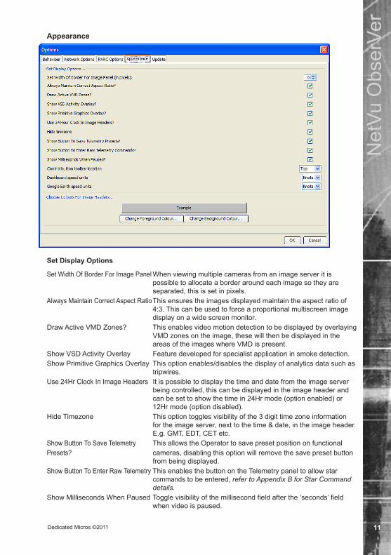
Appearance
ENGLISH
Set Display Options
Set Width Of Border For Image Panel When viewing multiple cameras from an image server it is possible to allocate a border around each image so they are separated, this is set in pixels.
Always Maintain Correct Aspect Ratio This ensures the images displayed maintain the aspect ratio of 4:3. This can be used to force a proportional multiscreen image display on a wide screen monitor.
Draw Active VMD Zones? This enables video motion detection to be displayed by overlaying VMD zones on the image, these will then be displayed in the areas of the images where VMD is present.
Show VSD Activity Overlay Feature developed for specialist application in smoke detection.Show Primitive Graphics Overlay This option enables/disables the display of analytics data such as
tripwires.Use 24Hr Clock In Image Headers It is possible to display the time and date from the image server
being controlled, this can be displayed in the image header and can be set to show the time in 24Hr mode (option enabled) or 12Hr mode (option disabled).
Hide Timezone This option toggles visibility of the 3 digit time zone information for the image server, next to the time & date, in the image header. E.g. GMT, EDT, CET etc.
Show Button To Save Telemetry This allows the Operator to save preset position on functional Presets? cameras, disabling this option will remove the save preset button
from being displayed.Show Button To Enter Raw Telemetry This enables the button on the Telemetry panel to allow star
commands to be entered, refer to Appendix B for Star Command details.
Show Milliseconds When Paused Toggle visibility of the millisecond field after the ‘seconds’ field when video is paused.

Dedicated Micros ©201112
Net
Vu O
bser
Ver
Control button toolbar location This option enables the tool bar options to be placed either at the top, bottom, left or right of the screen.
Dashboard speed units The Dashboard view is only used in conjunction with a TransVu unit. The Dashboard display includes a speedometer showing the estimated speed of the vehicle containing the TransVu. This speedometer can display the speed in MPH, KPH and Knots.
Google Earth speed units NetVu ObserVer can display the GPS positioning information on a dynamic map display. Google Earth uses this setting to display the data correctly.ENGLISH
Choose Colours For Image Headers
Change Foreground Colour It is possible to change the colour of the image header where the camera number, camera name and time and date are displayed. This option allows the text colour to be selected.
Change Background Colour The background colour can also be changed to best display the text colour selected.
Update
Update Site NetVu ObserVer can be configured to automatically update when a new version is released. The Update link will automatically populate with the correct address. To disable this feature, click the ‘Disable’ button.
Report errors automatically To aid in the development and improvement of this software, this feature will automatically send information of any errors or software problems experienced to Dedicated Micros, no personal data will be transferred.
ENGLISH

Dedicated Micros ©2011 13
Net
Vu O
bser
Ver
Structuring the site treeNetVu ObserVer provides a site tree to allow folders, image servers and cameras to be easily selected. The site tree will display all image servers that the Operator can access, this information will be provided either by using an existing site tree created with previous versions of NetVu ObserVer or by manually adding (and configuring) image servers to the tree.
An existing site tree can be accessed via the ‘Choose Site Folder’ option in Tools -> Options -> Behaviour menu.
ENGLISH
Adding a FolderFolders can be added to the site tree allowing related image servers to be grouped together within one area ensuring the site tree is ‘User friendly’ for the Operator.
To add a new folder to the tree structure of NetVu ObserVer, right click on the folder that will hold the new connection and select ‘New Folder’.
1. Highlight the Stored Image Servers Folder, or if a sub-folder (a folder within a folder) is required highlight the top level folder.
2. Click the right mouse button and select the Create New Folder option. The following prompt will be displayed.:
ENGLISH
3. Enter the name that will be given to the new folder and click OK, a folder will be added to the site tree. The folder name should be of relevance to the area being monitored, e.g. Main Office Building, High Street, Town Centre.
Image Servers and Decoders can now be added to the folder, or a sub folder can be created if required.
4. Highlighting the new folder, clicking the right mouse button will provide the Operator with the following options:
Create New Folder Will allow the quick creation of a folder in the current mouse position in the site tree
Add Image Server/Decoder Will launch the Image Server properties window in the Basic view described below.
Refresh Refreshes the site tree.Note: F5 on PC keyboard will perform the same action.
ENGLISH

Dedicated Micros ©201114
Net
Vu O
bser
Ver
Adding an Image Server to a FolderAn image server can be added to a folder to allow the Operator to easily select the unit and cameras for viewing and control. To add an image server to the site tree, right click on the folder to hold the new connection and select ‘Add Image Server’.
Basic Image Server Properties Menu
Required InformationName Enter a suitable name of the image server that will be displayed in
the site tree (for display only, this does not effect connectivity).IP Address or Domain Name Enter the IP address or URL of the image server. This will allow
a connection to be automatically established between the PC running the ObserVer application and the image server when selected from the site tree.
Additional Information The Additional Information is optional data that can be added to
the server being configured and can used by the Operator.Site ID This MUST match the ‘Alarm server ref. ID’ as defined in the
‘Remote Reporting’ section of the image servers settings. This parameter is used when the site sends alarms into the RVRC.
Site Plan Image File It is possible to allocate a site plan to each server, this can be accessed by the Operator and can be used to identify where the image server is installed and where cameras are located, which will appear as a tab, next to the Live video, when connected to the site. Using the ‘Browse’ button locate the site plan and select ‘Open’.
Note: This is a diagram and is not interactive, formats supported are GIF, JPG, PNG or BMP.Site Info Text File It is possible to supply site information to the Operator in a text
format, this information could be the contact details of the main key holder, etc. which will appear as a tab, next to the Live video, when connected to the site. Using the ‘Browse’ button locate the text file and select ‘Open’.

Dedicated Micros ©2011 15
Net
Vu O
bser
Ver
Note: Formats supported are RTF & TXT.Security SettingsUsername and Password The image server can be password protected. ‘Remote Viewer’
username and password, as set on the server, can be saved here to allow automatic connection to that server.
FTP Username and Password A password can be configured on the image server to ensure only authorised users can establish an FTP connection with the unit, which enables remote archiving of video data only, using the raw archive facility. The username and password can be saved here.
Display SettingsShow Disconnected Cameras in Tree When making a connection to the image server it is possible to
display the enabled cameras only or all cameras on the server. Enabling this option will show all camera inputs.
Note: If this option is enabled, the disabled cameras (as configured on the image server) will be ‘greyed’ out and will not be active in the application.
ENGLISH
Show Telemetry Controls for All Cameras Telemetry controls are only displayed when a camera has been enabled for telemetry on the image server. This option can force telemetry controls to be displayed at all times.
Advanced Image Server Properties MenuENGLISH
1. Select the Advanced tab, enter the relevant information into the Advanced configuration screen and click OK. The image server will now be added to the site structure.

Dedicated Micros ©201116
Net
Vu O
bser
Ver
Network SettingsLimit Bandwidth When the Operators workstation is located remotely from the
image server or a limitation has been imposed to bandwidth available for video, it is possible to set the speed of network transmission which will ensure the data is transmitted at the limited speed. The options available are:
Unlimited Default setting when the image server is connected to the same
LAN as the PC running the ObserVer application. These settings would be used in applications where the bandwidth available for the video images is not restricted.
512, 256, 128, 64, 32, 16 or 8KB/s These settings can be used to limit the speed of the network
connection, this is useful in applications where bandwidth is an issue.
Connect using WAN Mode Identifies the number of images that are buffered in the image server. The normal setting is 3, selecting WAN will automatically change this to 1. This is more suitable when viewing images across a slow speed link and will mean that when switching between cameras, images from the new camera will not need to wait for the buffer to empty before sending new video images.
Initial Connection Settings It is possible to select parameters that will be applied when making an initial connection to the image server.
Start on Camera This identifies the first display camera, i.e. if a single display is selected this is the camera that will be viewed. If a multi-screen display is selected, this is the first camera that will be displayed and all consecutive (enabled) cameras will be displayed in the remaining multi-screen segments.
Use Layout This option identifies the screen display mode that will used when this server is selected from the site tree. The options are Single, Four Way, Nine Way and Sixteen Way.
Resolution (Single, Quad, Other) Identifies the resolution of the images that will be transmitted to the application from the image server in Live and Playback mode. This uses the ‘Live Transmission Profiles’ setting on the image server. This setting should take into account the network connection available between the image server and the monitoring location, by default this should be; Single Resolution: High. Quad Resolution: Medium. Resolution Of Other Layouts: Low. The Live Transmission Profile is on a per camera basis.
Request Image format NetVu Connected devices support JPEG and MPEG-4 compression (default setting - MPEG-4). This setting selects the transmission format that a site will use by default.
Note: By using conditional image updating, MPEG-4 provides high quality images at a lower bit rate and would be more appropriate for systems where the network connection between the image server and ObserVer application is limited. JPEG uses full frame update and provides the best evidential integrity.
Transcode Settings This allows you to set the Transcoding that will be applied to the image stream from this server, using the Transcoding profiles available in Options->Network Options-> Transcoding Profiles.
Request Appendices This is an advanced configuration and allows text to be appended to image requests. This is used in retail applications where displayed text data is from tills or ATM’s and is appended to the text stream.
ENGLISHENGLISH

Dedicated Micros ©2011 17
Net
Vu O
bser
Ver
Adding an Decoder to a FolderA decoder can be added to a folder to allow the Operator to easily select the unit and cameras for viewing and control. To add a decoder to the site tree, right click on the folder to contain the new connection and select ‘Add Decoder’.
1. Enter the IP Address or DnDS name if the encoder and click OK. NetVu Observer will connect to it and display the first connected camera.
Configure Image Server via BrowserThis option is within the Tools menu and allows the Operator to access Web Configuration pages of the selected image server.
Note: This option will only be available when connected to an image server.When selected, a web browser (Explorer, Netscape, etc) will automatically be launched and the highlighted unit’s web pages will be displayed.
ENGLISH
View MenuThe View menu is used to show or hide sections of the controls.
ENGLISH
Image Server TreeDisabling this option would remove the site tree from the viewed window, this would remove the ability to select an image server, therefore making the workstation using this instance of NetVu ObserVer a viewer only unit. Links to hidden servers would still be accessible via any configured embedded map.
This option is enabled by default.
Activity Log, Embedded Data and RelaysThese are covered in the Additional Functionality section of this manual.
ENGLISH
Remote EventsThis enables the window that allows the User to login to the Event Distribution Point software. Please refer to the Alarm Receiving Functionality section of this document for further details.ENGLISH

Dedicated Micros ©201118
Net
Vu O
bser
Ver
OpenStreetMapThis feature is used with mobile servers (TransVu, PatrolVu) and displays the GPS positioning information on a dynamic map display. It can be used in Live and Playback modes. The pin symbol (bottom right) locks the map above any other windows, even when focus is changed.
Interactive MapThis allows any configured interactive map to be displayed or hidden. Interactive maps can be created using the freely downloadable software from the Dedicated Micros Website.
Note: Refer to “Using the Interactive Map Feature” section for further details.““
KeyboardThe keyboard controls can be hidden from the application when a server is selected, which means an Operator would not be able to control the cameras being viewed, providing a monitoring only station. This would be used where only fixed cameras will be used.
This option is enabled by default.
Note: NetVu ObserVer must be connected to an image server for this option to be available.ENGLISH
Dynamic Vehicle Data DisplaysThe Dynamic Vehicle Data Displays option allows vehicle information to be displayed within the ObserVer application. This is functional when used in conjunction with Dedicated Micros mobile video products such as the TransVu.
This can be enabled or disabled depending on the requirements of the application.ENGLISH
Dedicated Micros ©2011 19
Net
Vu O
bser
Ver
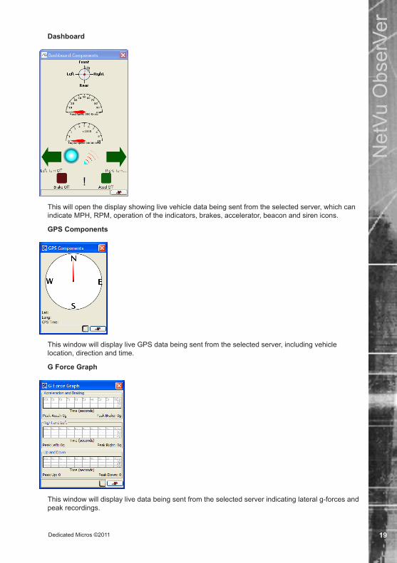
Dashboard
This will open the display showing live vehicle data being sent from the selected server, which can indicate MPH, RPM, operation of the indicators, brakes, accelerator, beacon and siren icons.
GPS Components
This window will display live GPS data being sent from the selected server, including vehicle location, direction and time.
G Force Graph
This window will display live data being sent from the selected server indicating lateral g-forces and peak recordings.ENGLISH
Dedicated Micros ©201120
Net
Vu O
bser
Ver
Help MenuThe Help menu provides a link to the Dedicated Micros Website, which can be used to check the latest version of software is running on the PC.
The ‘Gather Log Files’ option will collect all the log files into a single zip file, useful for archiving or sending to Technical Support at Dedicated Micros.
There is also a link to the about screen providing information about the version and release dates of the NetVu ObserVer software.ENGLISH

Dedicated Micros ©2011 21
Net
Vu O
bser
Ver
NetVu ObserVer ControlsNetVu ObserVer is the Operator interface which provides access and control of the functionality supported on NetVu Connected devices. The software allows connection to be made to a single or multiple devices offering central monitoring capabilities for one or several remote locations.
The Operator controls supported by the Viewer are described within this section and are separated into:
• Connecting to image servers for viewing and control. • Common controls - controls available in both Live and Playback mode. • Controls available in Live mode only. • Controls available in Playback mode only. • Miscellaneous - additional functions that are not related to the operating mode.
Note: Reference will be made to functionality that is not available when controlling non NetVu Connected DVR’s.
ENGLISH
ENGLISH
Connecting to an Image ServerThere are a number of ways to connect to an image server. Each will be described separately.
Temporary Image ServersTo connect to a temporary image server:
1. Type the IP address or Domain name of the unit into the edit box at the base of the site tree panel. NetVu ObserVer will also display any NDNS servers available on the network within this drop down.
ENGLISH
2. Select the Add button and the image server will be added to the site tree within the Temporary Image Server. The image from the first enabled input will then be displayed in the viewer window.
3. Temporary Image Servers can be moved to the site tree. Disconnect from the Image Server, then drag the it into the ‘Stored Image Server’ folder or subfolder.
ENGLISH
ENGLISH
Stored Image ServersTo connect to a stored image server:
1. If the folder entries are not visible, double click the folder name or click on the + to the left of the folder name to expand the tree view. Select the folder which contains the image server.
2. Highlight the image server to display the first enabled camera.ENGLISH

Dedicated Micros ©201122
Net
Vu O
bser
Ver
ENGLISH
Existing SitetreeTo open an existing site tree:
1. Select Tools -> Option.ENGLISH
2. Select the Browse option alongside the Choose Root Folder and locate the database file (default location C:\Documents and Settings\<username>\Application Data\ObserVer\sites).
3. Select Open, this will add the database image servers to the site tree.4. Open the folder that contains the image server to be viewed. Double click on the image
server, this will display the first enabled camera.ENGLISH
Disconnecting from an Image ServerIt is possible to disconnect all connections within NetVu ObserVer application, disconnect from a specific image server or drop the connection to a camera only.
Disconnect From AllThe Disconnect From All button will drop all connections between NetVu ObserVer and any image servers being controlled.
ENGLISH
Disconnect From an Image ServerTo disconnect from a specific image server, highlight the unit in the site tree and press the right mouse button to display a set of options.
Disconnect From This Image Server This option to drop the connection with the selected image server.Disconnect From All This option will drop all connections between the application and any
selected image servers.Delete This will permanently delete the selected image server from the site
tree.Properties This will provide access to the configuration parameters for the
selected image server, refer to Adding an Image Server to a Folder section for full configuration details.
ENGLISH
Disconnect From a CameraIt is possible to select an individual camera on any of the image servers and drop the connection between the ObserVer and that camera only.

Dedicated Micros ©2011 23
Net
Vu O
bser
Ver
To disconnect from a camera, highlight the camera within the site tree and press the right mouse button, this will display the following options.
Disconnect All Instances This will drop all connections with that camera, therefore whether a of This Camera camera is being viewed in one or more segments of a multi-screen,
the camera will be disconnected.Disconnect From This Image Server This will drop the connection between the ObserVer and the image server.
All cameras on this server will be removed from the display.Disconnect From All This option will drop all connections between the application and
connected image servers.
Using the Interactive Map FeatureThis software incorporates the ability to create and view Interactive maps.
Maps are created for each site using the map editor feature. Maps should be created as part of the installation procedure.
Creating / ENGLISHEditing the Interactive MapsTo edit the map, select View -> Edit Interactive Map.
A map can be created for each server with cameras attached. If a server nested within another folder has no map attached, the map for the parent folder will be displayed. If there is no map within the tree, the blank canvas will be displayed.
One main map can be created for every server shown. This map will be displayed when connection is made to the site. Up to six sub-levels can be added to each map. Each sub level can have cameras attached to it.
There are two methods of organising the viewing structure within the map editor.
For operator convenience, a single top level map can be created, with sub-maps that link all servers under the operator’s control. This suits applications where multiple servers are monitored by a single operator, and would result in quicker navigation and easier operator access. However, this method will not automatically display the map when an alarm is received.
Alternatively, maps can be created for each server. This means the operator will have to use the site tree to navigate between different sites, but the operator benefits as the relevant map is displayed when an alarm is raised. This facility will help operators quickly familiarise themselves with the layout of a site when an alarm activation occurs.
These methods are not exclusive and can be combined.

Dedicated Micros ©201124
Net
Vu O
bser
Ver
Highlight a folder in the server tree and select View -> Edit Interactive Map to begin creating a Map. The background area displays the ‘Under Construction’ symbol to show the edit feature is enabled.
Right click the working area to open the edit menu.
Select ‘Edit top level map’ to add the main map. The navigation box that appears allows the selection of the image to be used as the main map.
Important: Copy all the maps to be used into the NetVu Observer folder local hard drive and link them from this location.
Give the map a relevant name of your choice (or leave it empty) and then navigate to the image to be used as the background map. Click “Ok” to insert this file. The screen will display the background on the canvas area
Adding a layerThe software supports the creation of multi-layer maps. Additional maps can be added to show, for example, cameras within buildings.
Right click on the background map and select ‘Add new map’. Enter a suitable name for the map being created. The ‘Map filename’ refers to the next image that will be opened on screen (ie the floor plan).

Dedicated Micros ©2011 25
Net
Vu O
bser
Ver
The ‘Icon filename’ dialog box can contain a standard icon, or it can duplicate the entry in Map filename. If the Map filename is duplicated, the software will generate a small version of the map image as an icon. If ‘Icon filename’ is left empty, the software will generate an invisible ‘hot-spot’ on the background map, the title box of the icon will locate the hot-spot. The cursor will change from an arrow to a finger when over the hot-spot.
Press “Ok” to create the new layer to the map.
Adding CamerasIndividual cameras can be added in one of two ways.
a) NetVu Connected cameras can be ‘drag and dropped’ onto the map. A default icon will be used to mark the camera location. Right click on the icon to open the camera dialog box and edit the name of the camera or the icon used. The icon size can be altered via the dialog box, or by positioning the icon on the edge of the icon (until the cursor changes to a diagonal arrow) and dragging the icon on screen. The icon can be repositioned by moving the cursor to the centre of the icon (until the cursor changes to a four-way arrow) and then dragging it.
b) If not connected to NetVu servers, right click on the background image and select “Add camera” from the pop up menu. This will launch a dialog box. Data added to the ‘Name’ dialog will be displayed underneath the camera icon on screen. The ‘IP address’ dialog should be populated with the address of the image server, and the ‘Camera’ dialog is the camera number on that server. The ‘Resolution’ option gives you the option to select the default resolution to be displayed. The ‘Image filename’ enables the selection of one of thirteen standard camera icons, and offers the ability to upload a custom icon (using jpg for an opaque icon, or png or gif file format if transparency is required). The icon size, as a percentage of the original, can be set via this dialog, or it can be adjusted dynamically once it is displayed on the main edit screen by dragging. Click ‘Ok’ to accept these settings.
Right click on the canvas to add another layer. Up to six layers of maps can be nested within the top level in this way, depending on the complexity of the site. Add the floor plan for the building to this level.
Double click to open the sub map. Cameras can be added to the nested map at any level by right clicking on the image or dragging from the list on the left hand side and editing the placed icon.
Click ‘Edit’ to come out of editing mode.
The file is automatically saved as it is edited. Because it is saved in the common area shared with NetVu ObserVer, it will be available under the ‘View’ option in the ObserVer software.
Viewing the Interactive MapsTo view a map, select View -> Interactive Map.
The top level map associated with this site will be displayed.
Note: The controls within NetVu ObserVer remain the same when using the map facility. It provides quick and easy navigation for Operators.
ENGLISH

Dedicated Micros ©201126
Net
Vu O
bser
Ver
Click on one of the sites to open the submapENGLISH
Double click on one of the cameras to display it in the selected segment in the ObserVer software. Alternatively, the camera icon can be dragged and dropped into a segment to display it.
Navigate back to the top level of the map by right clicking on the map. In Multisite mode, it is possible to select another site from the top level.
Cameras from one image server can be displayed alongside images from different servers. When cameras from different servers are shown on-screen, the map will automatically navigate back to the top level.

Dedicated Micros ©2011 27
Net
Vu O
bser
Ver
Common ControlsThis section outlines the functionality that is common to both Live and Playback operating modes and explains how the functionality corresponds to the buttons within NetVu ObserVer.
Camera SelectionSelecting a camera is achieved using the site tree, the site tree displays the Image Servers that are currently being controlled as well as the enabled camera inputs on each server. Depending on whether the application is in single-site mode or multi-site mode the following will apply:
ENGLISH
To select a camera or cameras;Single-site mode Clicking the mouse on the image server will result in input 1
of the unit being displayed (default), as long as it is connected and functional. Selecting a multiscreen display will result in the consecutive images on the server being cascaded in the multiscreen display - the number of consecutive cameras will depend on the cameras enabled and the display format selected.
Note: If a multiscreen display has been selected in the Properties option, when selecting the image server, the application will display the multiscreen and cascade the cameras starting from input 1.
ENGLISH
Single and Multi-site Mode Highlight the required camera and ‘drag’ this to the position on the screen where the camera is to be displayed, the camera will be displayed in the full or multiscreen segment selected,
or; Select a monitor position (if multiscreen is displayed) and then
double click the mouse on the camera, the images from the camera will be displayed.
Note: If the image server has been configured to identify camera failure, a ‘Camera Fail’ Image will be displayed on the relevant input (displayed as a NetVu Connected Logo with a Camera Fail symbol in the bottom right of the screen) if the camera input is not available or faulty.
ENGLISH
Duplicating an ImageWhen a camera is displayed in a multiscreen display it is also possible to create a ‘duplicate’ of that camera. Select the segment where the camera is displayed and ‘drag and drop’ the camera to the new position that you want the camera to be shown, the image will be displayed in both segments.
Swapping cameras in a segment. Select the camera to be swapped in the multiscreen display and drag it into the new position. The cameras will swap positions.
ENGLISH

Dedicated Micros ©201128
Net
Vu O
bser
Ver
Display ModeNetVu ObserVer supports multiscreen viewing to allow numerous video images to be viewed simultaneously, this can be from any number of different image servers.
Note: Refer to the Appendix for full details of the display options available.ENGLISH
The display option can be selected from the drop down list.
The multiscreen formats are available in Live and Playback mode.
The following details the image format groups supported in NetVu ObserVer application.
Single A single screen of the selected camera will be displayed in live or playback mode. When selected the last camera being controlled will be displayed.
Quad A quad display with the selected camera and the next three sequential (enabled) video inputs, e.g. cameras 4, 5, 6, 7 will be displayed. If the sequential video inputs are not enabled then a blank screen will be displayed in live or playback mode.
ENGLISH
Instead of displaying sequential images it is possible to select which camera is to be viewed in each segment. Click on a segment to highlight it and press the corresponding camera button to be displayed.
Picture in Picture It is possible to display a picture as an overlay of the main picture, the overlay can be a single or quad display. When a picture in picture display is selected the main window will display the last selected camera and the next (enabled) sequential image(s) will be displayed in the overlay section.
ENGLISH
Instead of displaying sequential images it is possible to select which camera is to be viewed in each segment. Click on a segment and press the corresponding camera button to be displayed.
Multiscreen Up to a 36 Way view can be selected in a number of variations, allowing up to thirty-six separate sites to be viewed using NetVu ObserVer at any one time.
ENGLISH
It is possible to identify where video inputs are to be viewed within the multiscreen.
Select the relevant segment (click on the segment) and select the camera from the site tree for the live or recorded image to be displayed in that segment.
It is possible to select a segment within the display, when a segment is selected a coloured box will appear around the segment to indicate control. Double clicking on a segment will toggle the display between full screen and multiscreen views. When in Full Screen view it is not possible to use the Display mode button to change it back to multiscreen, only full screen is displayed. Double click the full screen image to return back to the previous multiscreen display.
ENGLISH

Dedicated Micros ©2011 29
Net
Vu O
bser
Ver
Resolution Selection
Although the resolution of the video from an image server can be configured with the Properties option (refer to Adding an Image Server ) the ObserVer application also provides the ability to select the resolution of the images being viewed in Live and Playback mode.
This feature is useful when a slow speed link is being utilised for remote monitoring, reducing the resolution will reduce the amount of information that is being transmitted from the image server, and can provide faster image update providing easier control of telemetry cameras or more coherent viewing.
A resolution request is sent from NetVu ObserVer application to the image server, the unit will then apply the resolution settings stored within it’s configuration to the images being transmitted to the viewer. The resolution settings are defined in the ‘Live Transmission Profile’ settings on the image server. These are MJPEG/MPEG, Filesize/Rate, PPS and MPEG4 type, quality and I frame Ratio. See the image server installation guide for further details.
Note: The selected viewing resolution (high, medium, low) applies to all cameras being viewed.Note: Image servers are able to re-compress, or transcode, recorded images during the playback
process; this will reduce the size of the video image when using a slow remote link.ENGLISH
High resolution is the optimum video image that will have a set resolution and files size associated – Live and Playback mode.
ENGLISH
Medium is a lower quality video stream that is sending less information with a reduced file size – Live and Playback mode.
ENGLISH
Low is the lowest video quality and has a low file size allocated.
Note: If the Live web page of the image server is used for viewing it is possible for multiple Operators to make connections to the unit and view the same camera at different resolutions.
ENGLISH
Audio Control
Image servers support bi-directional audio communication.
The audio controls in NetVu ObserVer allow audio connections to be established between the application and an image server allowing live audio to be transmitted and received.
These controls can also be used in playback mode if audio has been recorded alongside the video. The Operator can then select the speaker buttons to hear the audio while reviewing the video images.
The audio buttons are latched and allow the Operator to switch the audio on (establish audio connection) or off (drop audio connection).
Speaker 1 Speaker 1 enables the operator to listen to the associated audio from the site. This channel will always play audio input 1 with camera 1 and audio input 2 with camera 2, in live or playback.
Speaker 2 Speaker 2 enables the operator to listen to the audio from ObserVer which has been transmitted to the site. This only operates in playback and can be used to check what an operator has broadcast to a remote site’s external loudspeakers.
Mic 1 Enables the transmission from a microphone on the monitoring station to loudspeakers on site. This is to enable operators to challenge people on site or issue warnings.
ENGLISH

Dedicated Micros ©201130
Net
Vu O
bser
Ver
Freeze on a Single ImageIt is possible to use the VCR pause button in live mode to freeze the images that are being displayed. This allows an Operator to view in more detail the frozen image to determine if an incident is occurring. Freezing the live video will not affect the recorded images.
The pause button operates in the same way when in playback mode, pressing the pause button will pause the video being reviewed.
ENGLISH
Display PresetsNetVu ObserVer supports the ability to save a Display Preset.
The application remembers the image servers being controlled, the cameras inputs being viewed and the position in which the images are displayed when a display preset is saved.
Note: This does not apply to any Temporary image servers that are selected for view, it will only recall the Stored image servers and corresponding cameras.
This view can then be selected at any time and the software will automatically re-establish the connections to the relevant image servers and display the correct camera inputs in the correct location.
Select File -> Save Display Preset;ENGLISH
Enter a relevant name for the display for easy selection.
Dedicated Micros ©2011 31
Net
Vu O
bser
Ver
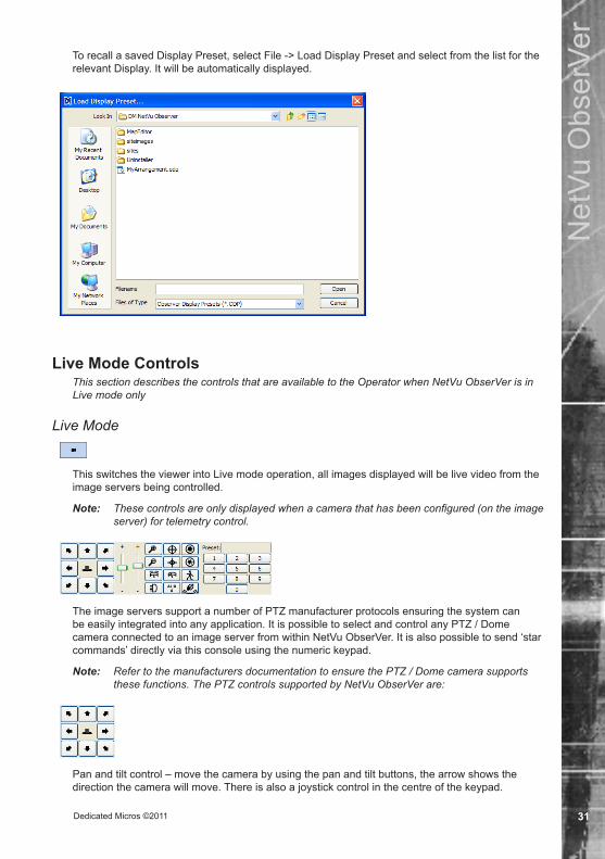
To recall a saved Display Preset, select File -> Load Display Preset and select from the list for the relevant Display. It will be automatically displayed.
ENGLISH
ENGLISH
ENGLISH
Live Mode ControlsThis section describes the controls that are available to the Operator when NetVu ObserVer is in Live mode only
Live Mode
This switches the viewer into Live mode operation, all images displayed will be live video from the image servers being controlled.
Note: These controls are only displayed when a camera that has been configured (on the image server) for telemetry control.
ENGLISH
The image servers support a number of PTZ manufacturer protocols ensuring the system can be easily integrated into any application. It is possible to select and control any PTZ / Dome camera connected to an image server from within NetVu ObserVer. It is also possible to send ‘star commands’ directly via this console using the numeric keypad.
Note: Refer to the manufacturers documentation to ensure the PTZ / Dome camera supports these functions. The PTZ controls supported by NetVu ObserVer are:
ENGLISH
Pan and tilt control – move the camera by using the pan and tilt buttons, the arrow shows the direction the camera will move. There is also a joystick control in the centre of the keypad.
ENGLISH
Dedicated Micros ©201132
Net
Vu O
bser
Ver
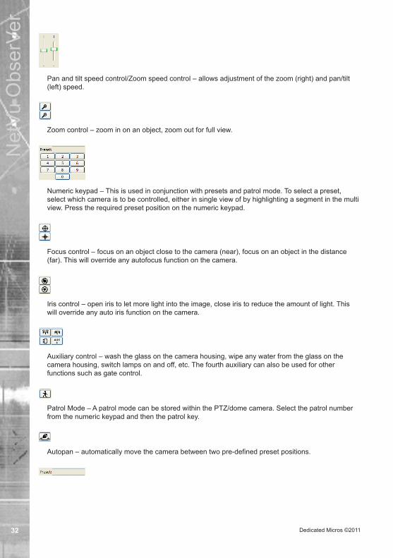
Pan and tilt speed control/Zoom speed control – allows adjustment of the zoom (right) and pan/tilt (left) speed.
Zoom control – zoom in on an object, zoom out for full view.ENGLISH
Numeric keypad – This is used in conjunction with presets and patrol mode. To select a preset, select which camera is to be controlled, either in single view of by highlighting a segment in the multi view. Press the required preset position on the numeric keypad.
ENGLISH
Focus control – focus on an object close to the camera (near), focus on an object in the distance (far). This will override any autofocus function on the camera.
ENGLISH
Iris control – open iris to let more light into the image, close iris to reduce the amount of light. This will override any auto iris function on the camera.
ENGLISH
Auxiliary control – wash the glass on the camera housing, wipe any water from the glass on the camera housing, switch lamps on and off, etc. The fourth auxiliary can also be used for other functions such as gate control.
ENGLISH
Patrol Mode – A patrol mode can be stored within the PTZ/dome camera. Select the patrol number from the numeric keypad and then the patrol key.
ENGLISH
Autopan – automatically move the camera between two pre-defined preset positions.ENGLISH

Dedicated Micros ©2011 33
Net
Vu O
bser
Ver
Direct Telemetry Control –Allows star commands to be sent directly to the camera. The Preset window above the telemetry keypad changes to a command input window. Commands are input via the numeric keypad, refer to Appendix for a selection of commands available. Star commands are entered via the numeric keypad ON THE COMPUTER KEYBOARD. Click the star key on the keypad, then enter the command via the computer keyboard and press the Enter key on the computer keyboard. This will send the command to the camera.
Save preset–allows the operator to save preset positions for functional cameras. This will only be active if enabled in the application.
ENGLISH
Important InformationIt is possible to use VMD (Video Motion Detection) on moveable cameras that are connected to NetVu Connected image servers (this feature does not apply to non NetVu Connected DVR’s).
Ensure that the camera has been configured correctly on the server so that, if VMD is active, the camera is set up to have VMD inhibited when it is moving.ENGLISH
MPEG4/MJPEG
In Live mode, MJPEG or MPEG 4 video can be selected for viewing. Using MPEG4 reduces the bandwidth required to view remote scenes, and when configured on the server, it can provide more fluid moving video over reduced bandwidth connections.
NetVu Connected servers can playback TransCoded video from the site.
In Playback mode, if the video has been recorded in MJPEG then it can be either viewed as the recorded MJPEG or TransCoded to MPEG4 for viewing over reduced bandwidth links with improved image update rates, eg if a high definition MJPEG stream, or real time D1 stream was recorded on a channel representing 1-2 Mbits per channel, and was viewed remotely over a link that only supports 256k data rates. If the server is using MultiMode recording (MJPEG and MPEG4 recording) the operator can either view recordings in the recorded format (MPEG4/ MJPEG) by selecting the MJPEG option, or Transcode them to MPEG4 by selecting the MPEG4 button, refer to Tools->Options->Network Options->Transcode Profiles for details on configuring Transcoding profiles.
Note: It is not possible to TransCode from recorded MPEG4 to MJPEG for transmissionNote: This is an application level command and will change ALL images being displayed within
NetVu ObserVer. It does not just apply to the image currently being viewed.ENGLISH
Note: This option is not available on non NetVu Connected DVR’s (previous versions of Eco, DS2 and BX2), these units transmit MJPEG images only.
Dedicated Micros ©201134
Net
Vu O
bser
Ver
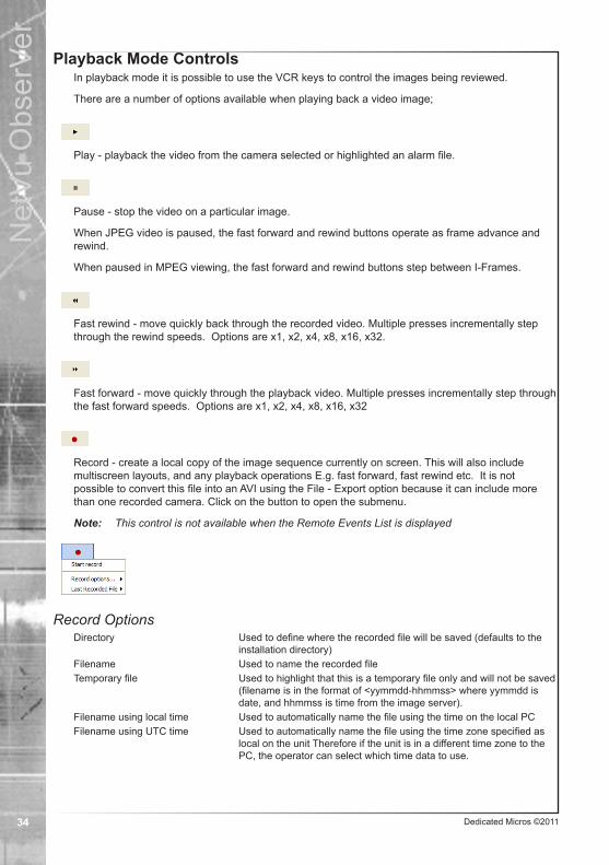
Playback Mode ControlsIn playback mode it is possible to use the VCR keys to control the images being reviewed.
There are a number of options available when playing back a video image;ENGLISH
Play - playback the video from the camera selected or highlighted an alarm file.ENGLISH
Pause - stop the video on a particular image.
When JPEG video is paused, the fast forward and rewind buttons operate as frame advance and rewind.
When paused in MPEG viewing, the fast forward and rewind buttons step between I-Frames.ENGLISH
Fast rewind - move quickly back through the recorded video. Multiple presses incrementally step through the rewind speeds. Options are x1, x2, x4, x8, x16, x32.
ENGLISH
Fast forward - move quickly through the playback video. Multiple presses incrementally step through the fast forward speeds. Options are x1, x2, x4, x8, x16, x32
ENGLISH
Record - create a local copy of the image sequence currently on screen. This will also include multiscreen layouts, and any playback operations E.g. fast forward, fast rewind etc. It is not possible to convert this file into an AVI using the File - Export option because it can include more than one recorded camera. Click on the button to open the submenu.
Note: This control is not available when the Remote Events List is displayedENGLISH
Record OptionsDirectory Used to define where the recorded file will be saved (defaults to the
installation directory)Filename Used to name the recorded fileTemporary file Used to highlight that this is a temporary file only and will not be saved
(filename is in the format of <yymmdd-hhmmss> where yymmdd is date, and hhmmss is time from the image server).
Filename using local time Used to automatically name the file using the time on the local PCFilename using UTC time Used to automatically name the file using the time zone specified as
local on the unit Therefore if the unit is in a different time zone to the PC, the operator can select which time data to use.

Dedicated Micros ©2011 35
Net
Vu O
bser
Ver
Last Recorded FileBrowse to File Will open the folder containing the last saved recording.Replay last recorded file Will directly open the last saved recording.
ENGLISH
Increase/Decrease Playback SpeedsIt is possible to increase/ decrease the speed of video in playback mode. The drop down menu shown below is displayed when the arrow adjacent to the fast forward and rewind button is pressed.
By selecting one of the displayed options, the video can be played back at speeds ranging from a 1/4 of the normal rate to 64 times normal speed. The N mode will transmit video at the fastest possible rate without dropping or skipping pictures. The transmission speed, used in this mode will vary dependant on record rate and network transmission speed.
ENGLISH
Mousekey SubfunctionsRight clicking on a playing camera, or on a live camera view in the viewer will open the menu, allowing the User to alter the zoom level to 100%, 200%, 400% or 800%.
Right clicking on a paused image will enable additional functionality.
Save This will allow a jpg or a pdf in a User specified location (defaults to the installation directory). The jpg will have an accompanying text file of the same name which contains the entered text. The pdf will have the text embedded below the image in a single file. Default filename: <Server name-Camera Number-dd-mm-yy-hhmmss-ms> Available file types are JPEG, PDF or RTF. User Comment text are additional comments to be included in the saved text file or PDF.

Dedicated Micros ©201136
Net
Vu O
bser
Ver
Save as Reference This allows a camera reference image to be saved for future comparison. This image can then be used for visual comparison to check camera positioning, or when visibility is poor (fog, night) to identify features. The reference image is shown by right clicking on the camera in the site tree and selecting ‘View Reference Image’. It is possible to save multiple reference images for each camera. The reference image is saved in the site directory.
Copy to Clipboard This option allows an image to be saved to the Microsoft Office clipboard function. This image can then be incorporated in other PC based applications.
Print Page Setup This option allows print settings to be established prior to printing the image.
Print This sends the paused image to the printer.
Go To Time and DateIt is possible to review a specific video recording by selecting the time and date. Select the down arrow next to the date window to display a calendar where the time and date can be selected.

Dedicated Micros ©2011 37
Net
Vu O
bser
Ver
Enter the date and time required, ensuring the Time/Date drop down matches the time zone relevant to the search ie if the DVR is in a different Time Zone to NetVu ObserVer, set the drop down to the time zone of the DVR and select the Local (DVR) time to search. Press OK, any available video from the specified time and date will play.
ENGLISH
Event ListThe image server logs every event (as configured in the web configuration pages) to an event database. NetVu ObserVer can be used as the interface to access this database and allow the Operator to review the event list and any video recordings associated with the event.
When the Event List button is clicked, the event list for the image server will be displayed. An additional tab will also be added in the display window to allow the Operator to switch between the event list and live viewing.
ENGLISH
Note: The event list button is a latched button, when selected the event database for the server will be displayed, selecting again will switch the application back to view mode and remove the Event tab.
ENGLISH
Selecting Refresh will refresh the event list.ENGLISH
Previous EventENGLISH
Next Event

Dedicated Micros ©201138
Net
Vu O
bser
Ver
If an event has associated video recordings, highlighting and double clicking that event will display the recorded images. Alarm text will be displayed in the title header of the image.
When the images are being reviewed the Live tab will be renamed as Replay so the Operator can tell the mode of operation. Click on the Events tab to return to the list of events.
The number of events shown on a single page is configured in the Tools -> Options menu of NetVu ObserVer.
ENGLISH
Previous PageENGLISH
Next Page
Using the Previous and Next buttons allows you to step through the pages of events.ENGLISH
Highlighting an event and selecting right mouse button will also allow the Operator to:
• Refresh the Event List.• Get Previous 10, 50 or 100 Events.• Get Next 10, 50 or 100 Events.• Filter events by date, camera or alarm type.
ENGLISH
Dedicated Micros ©2011 39
Net
Vu O
bser
Ver
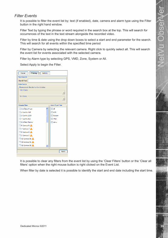
Filter EventsIt is possible to filter the event list by; text (if enabled), date, camera and alarm type using the Filter button in the right hand window.
Filter Text by typing the phrase or word required in the search box at the top. This will search for occurrences of the text in the text stream alongside the recorded video.
Filter by time & date using the drop down boxes to select a start and end parameter for the search. This will search for all events within the specified time period
Filter by Camera by selecting the relevant camera. Right click to quickly select all. This will search the event list for events associated with the selected camera.
Filter by Alarm type by selecting GPS, VMD, Zone, System or All.
Select Apply to begin the Filter.
It is possible to clear any filters from the event list by using the ‘Clear Filters’ button or the ‘Clear all filters’ option when the right mouse button is right clicked on the Event List.
When filter by date is selected it is possible to identify the start and end date including the start time.ENGLISH

Dedicated Micros ©201140
Net
Vu O
bser
Ver
ActivityThe unit provides the option to search the stored images for activity within defined areas, even if Activity detection was not enabled on the unit. Select the activity button on the Event screen to open the Activity filter.
A reference image is shown with a search grid superimposed on it.
Activity SettingsThe drop down options allow specific areas of the image to be used for activity detection. The top left, top right, bottom left and bottom right quadrants can be selected. An option also exists to create an activity detection block by clicking the mouse button within the reference image and dragging the mouse to create the block. Individual squares can also be selected via the final option.
The Activity Settings options also allows the Operator to specify whether the search is for ACT on, ACT off or ACT both.
ACT on Will search for when Activity startsACT off Will search for when Activity endsACT both Will search for when Activity starts and ends
The Camera Dwell time is the amount of time the camera is static during a patrol.
Camera FilterThe Camera Filter options allows the Operator to select which relevant camera they want to include in the activity search.
Please select the start and end datesEnter the start and end dates/times for the activity search.
ENGLISHThe Activity Parameters are used to define which camera will be searched and the Camera Dwell Time. The Camera Dwell time is the amount of time the camera is static during a patrol.
ENGLISH
ENGLISH
ENGLISH

Dedicated Micros ©2011 41
Net
Vu O
bser
Ver
Download Images
It is possible to download all associated recorded images from the hard drive of the image server to the local PC (or a networked PC) from a specified time and date. These files can then be played back using NetVu ObserVer software, refer to Additional Features, Replay Server section for details on how this feature operates.
Note: Although this option can be selected when controlling non NetVu Connected DVR’s (Eco, DS2 and BX2) this functionality is not supported and images can not be downloaded from these units.
To create an evidence CD1. Ensure there is a blank DVD or CD in the local PC drive and that it is writeable.2. If there are multiple Video Servers configured in NetVu ObserVer, ensure the correct
video server is selected in the Image Server Tree panel.3. Click on the Download icon to open the download dialog box.4. Select Raw or Filtered download. Raw will download all the data from all cameras
between the selected times (next step), Filtered allows camera selection.5. Set the period to be downloaded to disk by setting start and end date and time.6. If Filtered download has been selected, pick which cameras are to be downloaded in
the Camera Filter panel.7. Select which associated audio sources that are to to be downloaded with the video.8. Select if the download is to be as an Evidence CD/DVD or as an AVI file. If AVI is
selected, use the Browse button to select a location to export to.9. If the bandwidth is limited, use ‘pause video during download’ to speed up the download.9. Click on Start Download. Files will be downloaded to the connected computer. The
computer will be scanned for a suitable CD/DVD burning device to use and the CD or DVD will be created.
ENGLISH
There are two types of downloads;
Filtered Download

Dedicated Micros ©201142
Net
Vu O
bser
Ver
The filtered download page allows selection of the cameras to download along with a start and end time.
● Camera audio and challenge audio, just challenge audio can be added, or audio can be ignored.
● It is possible to format the export as an Evidence CD/DVD (which will include an embedded player), an AVI file (to be replayed on a computer) or as a DVD-Video file, for playing on a standard DVD player.
● Pause video during download will halt video playback during the download.
Raw Download
The raw download page also requires a Start and End time for the download, but will download all the data from all cameras between those times.
● It is possible to format the export as an Evidence CD/DVD (which will include an embedded player), an AVI file (to be replayed on a computer) or as a DVD-Video file, for playing on a standard DVD player.
● Pause video during download will halt video playback during the download.Select Download to download the images. This process may take a some time depending on the size of the video segment selected and the network connection to the unit.
ENGLISH

Dedicated Micros ©2011 43
Net
Vu O
bser
Ver
Alarm Receiving FunctionalityNetVu ObserVer can receive alarm notifications from NetVu Connected devices. These alarms can then be managed by the Operator for verification and acknowledgement.
The NetVu Connected installation for central monitoring stations consists of the NetVu ObserVer viewer and the Event Distribution Point software.
The EDP receives an alarm from a NetVu Connected device, logs it in a full SQL database and then serves it to one of the available NetVu ObserVer’s connected and logged on to the EDP. This is done according to a ‘rulebase’ which ensures that all alarms are answered according to their arrival order. The operator is then required to respond and close the alarm event providing a classification of the alarm, along with a comment if necessary. The EDP will serve further events from the NetVu Connected device during the same open session to that operator until the session is closed.
It is also possible for the monitoring station to then interrogate the EDP database to generate reports for billing or site maintenance purposes.
The EDP is designed to fully comply with BS8418.ENGLISH
Configuring the System for Alarm ReceivingNetVu Connected DevicesThe IP address of the EDP Server (the PC running the software) must be configured within the ‘Alarm/VMD Reporting’ option of all NetVu Connected devices that will report alarms to it, so that any alarm that is sent to it can then forwarded to the NetVu ObserVer. Applications where the alarm will be sent externally to the network via a router must enter the external IP address of that router. Port and data forwarding should then be configured on the router to direct the data to a specific internal LAN PC.
Important: Ensure all routers or switches between the EDP and the PC’s running NetVu ObserVer are UDP capable and that the protocol has been enabled. Disabling UDP can stop the EDP communicating with NetVu ObserVer.
The unit must also be configured to send alarm reports for specific conditions (alarms, activity, restart, etc.).
To receive alarms correctly, NetVu ObserVer needs to monitor the network for alarm messages from the EDP. To do this, NetVu ObserVer must be logged on to an Event Distribution Point server using a valid username and password. These are set up in the EDP software.
ENGLISH
If not already open, click on View->Remote Event List to open the Remote Events window to open the login window. The Username and Password are case sensitive. The EDP will distribute all alarms it receives between the logged on NetVu ObserVer users. Logging in with a valid password and using the EDP are explained in the section ‘Using the EDP from within NetVu ObserVer’.
Event Distribution Point SoftwareNetVu ObserVer can receive alarm notification from NetVu Connected devices. These alarms can be managed by the Event Distribution Point software.
The EDP receives an alarm, logs it and serves it to one of the available NetVu ObserVer’s connected and logged on to the EDP. The operator is then required to respond and close the alarm event providing a classification of the alarm, along with a comment if necessary. The EDP will serve further events from the same image server to the same open session with that operator until the session is closed.
Note: The EDP and NetVu ObserVer use UDP protocol and multicasting to communicate across the network. Ensure all switches and routers between the EDP and NetVu ObserVer are UDP capable.
Note: Ensure the text string used for Site ID (Image Server Properties : NetVu ObserVer) and for Unit alarm name (Network Options->Remote Reporting : On the unit) are the same.
Dedicated Micros ©201144
Net
Vu O
bser
Ver
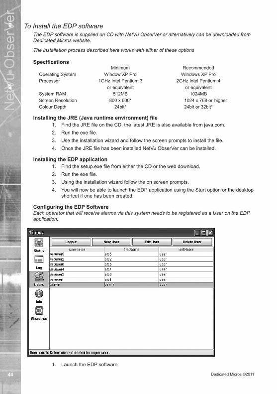
To Install the EDP softwareThe EDP software is supplied on CD with NetVu ObserVer or alternatively can be downloaded from Dedicated Micros website.
The installation process described here works with either of these options
Specifications Minimum RecommendedOperating System Window XP Pro Windows XP ProProcessor 1GHz Intel Pentium 3 2GHz Intel Pentium 4 or equivalent or equivalentSystem RAM 512MB 1024MBScreen Resolution 800 x 600* 1024 x 768 or higherColour Depth 24bit* 24bit or 32bit*
ENGLISH
Installing the JRE (Java runtime environment) file1. Find the JRE file on the CD, the latest JRE is also available from java.com.2. Run the exe file.3. Use the installation wizard and follow the screen prompts to install the file.4. Once the JRE file has been installed NetVu ObserVer can be installed.
ENGLISH
Installing the EDP application1. Find the setup.exe file from either the CD or the web download.2. Run the exe file.3. Using the installation wizard follow the on screen prompts.4. You will now be able to launch the EDP application using the Start option or the desktop
shortcut if one has been created.ENGLISH
Configuring the EDP SoftwareEach operator that will receive alarms via this system needs to be registered as a User on the EDP application.
1. Launch the EDP software.ENGLISH

Dedicated Micros ©2011 45
Net
Vu O
bser
Ver
There are four information panes available, labelled Users, Status, Log and Info.
Status Displays the current operation mode of the softwareLog This page will detail a database showing all received information from
connected units in SQL format.Users Allows administration of User accounts including creation, editing and
deletion and modifying passwordsInfo This page is used when contacting Dedicated Micros Technical
Support. It displays information on the different services being used by the database.
Shutdown Following confirmation of Username and Password, exit the EDP software via this option.
ENGLISH
Administering User Accounts
1. The first time the application is launched it will display the Users window with two accounts preloaded. The software requires an administrator to log in to add new User or admin accounts. The default username and password are admin and password respectively. These should be changed as soon as possible to maintain security. Click the Login button at the top of the pane and enter the administrator username and password.
ENGLISH
2. Once successfully logged in, the administrator will be able to Create, Edit and Delete Users, as well as change the password on any account.
ENGLISH
To create a new User;

Dedicated Micros ©201146
Net
Vu O
bser
Ver
1. Click on the ‘New User’ button. A dialog box will open.ENGLISH
2. Add information to all the required fields and click the ‘Add User’ button, or click ‘Cancel’ to abandon the operation.
ENGLISH
To edit a users details;
1. Highlight the User account to be edited and click on the ‘Edit User’ button. A dialog box will open.
ENGLISH
2. Change the information and click the ‘Edit User’ button, or click ‘Cancel’ to abandon the operation.
ENGLISH
To change a Password;
1. Highlight the User account and click ‘Change Password’. The dialog box will openENGLISH
2. Enter the original password in the correct box. Enter the new password, and repeat it in the second field. Click on ‘Change Password’ to confirm the change, or ‘Cancel’ to abandon the operation.
ENGLISH
To delete a User;1. Highlight the User account and click the ‘Delete User’ button. The account will be
immediately deleted. Ensure you select the correct account to delete as there is no confirmation stage.
ENGLISH
Using the EDP from within NetVu ObserVerThe EDP will distribute the alarms to connected NetVu ObserVer operators. An operator will need to log on from within ObserVer to use this facility.
To log into the EDP;Ensure that the settings for the EDP have been configured correctly. Click on ‘Tools->Behaviour’ and verify the settings in the panel named ‘Set ARC Options…’ are correct for the EDP server.
1. Open the EDP login window by clicking View -> Remote Event List.ENGLISH

Dedicated Micros ©2011 47
Net
Vu O
bser
Ver

Dedicated Micros ©201148
Net
Vu O
bser
Ver
2. Enter a username and password for a valid registered User on the EDP.ENGLISH
3. The system will display any forwarded alarms from the EDP in the Remote Events window.
ENGLISH
Adding Temporary Image ServerIt is possible to add an image server to the site tree on a temporary basis.
To add a temporary image server to the site tree:1. Type the IP address or domain name of the image server into the edit box at the base
of the site tree.ENGLISH
Event List - NetVu ObserVer will display all events within the event list, this will detail; the unit name, time & date, the camera input and the type of alarm.
ENGLISH
ENGLISH
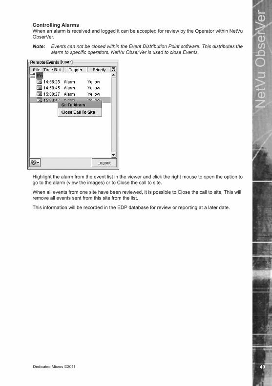
Dedicated Micros ©2011 49
Net
Vu O
bser
Ver
Controlling AlarmsWhen an alarm is received and logged it can be accepted for review by the Operator within NetVu ObserVer.
Note: Events can not be closed within the Event Distribution Point software. This distributes the alarm to specific operators. NetVu ObserVer is used to close Events.
Highlight the alarm from the event list in the viewer and click the right mouse to open the option to go to the alarm (view the images) or to Close the call to site.
When all events from one site have been reviewed, it is possible to Close the call to site. This will remove all events sent from this site from the list.
This information will be recorded in the EDP database for review or reporting at a later date.ENGLISH

Dedicated Micros ©201150
Net
Vu O
bser
Ver
Additional Alarm Information
It is possible to obtain more detailed information on any of the events within the Event List.
Move the mouse over the event until an event window pops up which contains more detailed information.
ENGLISH
The Heart logo at the bottom of the panel enables the operator to force ObserVer to check the connection to the EDP.

Dedicated Micros ©2011 51
Net
Vu O
bser
Ver
EDP Report GeneratorThe EDP Report Generator enables an RVRC to generate reports from information collated by the EDP. Typical report options are provided pre-configured with the software. It is however possible for an advanced user to create and establish specific reports according to their own chosen criteria.
To access the Report Generator;1. Ensure the EDP software is running and the NetVu Observer is logged on using a
correct username and password. 2. Launch the browser and navigate to http://127.0.0.1:8080/Reports
Note: If the EDP is not being run on the local machine, replace 127.0.0.1 with the IP address of the remote server.
The following opening menu will be displayed:
The default log-on details are:
username: admin
password: password
It is strongly recommended that the username and password be changed from these defaults at the earliest opportunity. Once login is complete, select a group from the Groups list. This option allows similar reports to be grouped together. For example; all fault report information could be collated under a ‘Technical Users’ heading. The EDP software is pre-configured with six report options. These options can be accessed via the Reports tab and then the Groups list, see below for detailed descriptions.
Generating ReportsAll reports require search parameters.
Client Activity Report1. Enter Start and End dates. Click ‘OK’.2. Choose an RVRC ID from the accompanying drop down list. Click ‘OK’.

Dedicated Micros ©201152
Net
Vu O
bser
Ver
3. The report can be displayed in any of the following formats: PDF, HTML, CSV, XLS, RTF, Text, Excel or as an Image. Select a format using the drop down box and click ‘Run’.
A report similar to that detailed below will then be displayed:
This Client Activity Report provides a full detailed alarm list for the site with specific reference to the times of the alarms.
Time Raised Details the time the alarm was initially raised.
Time Arrived The time that the EDP software received the alarm.
Time Accepted The time that the alarm was accepted by the EDP.
Time Closed The time the alarm was actioned and closed.
Note: The times detailed under the ‘Time Raised’ heading are based on the time settings of the Server (details are taken from the incoming alarm packet data). The other fields base their times on the settings of the EDP.
Operator Performance Report1. Enter Start and End dates. Click ‘OK’.
2. Select the data display format. When the required format has been selected, click Run.
The displayed report will detail individual Operator alarm response times; the amount of sessions handled, the Maximum (total) session time, and the average time the Operator has spent in each session. The average and maximum time the Operator has taken to respond to an incident will also be shown.
RVRC Activity Report1. Enter Start and End dates. Click ‘OK’.2. Choose an RVRC ID from the accompanying drop down list. Click ‘OK’.3. The report can be displayed in any of the following formats: PDF, HTML, CSV, XLS,
RTF, Text, Excel or as an Image. Select a format using the drop down box and click ‘Run’.
The displayed report can be used to filter alarm information for the specific site.
Please note that only those alarms that have been closed under the following criteria will be displayed; PCA - Possible Criminal Activity and CCA - Confirmed Criminal Activity.

Dedicated Micros ©2011 53
Net
Vu O
bser
Ver
RVRC Fault ReportEnter a Start and End date range and an RVRC ID, then select Ok. The data can be displayed in a variety of formats. When the required format has been selected, left-click Run.
The RVRC Fault Report can be used to filter fault related information for the specific site.
Note: Only those alarms which have been closed under the following criteria will be displayed; NVC - No Visible Cause, EFA - Environmental False Alarms, UVL - Unable To Verify/Lighting, VVW - Visually Verified/Widlife, UVO-Unable To Verify/Other and OVC-Other Visible Cause.
RVRC Performance Report1. Enter Start and End dates. Click ‘OK’.2. The four additional options then allow a User to establish a report based on a criteria of
upper and lower response time targets and actual response values.
Please supply the lower time percent Enter a lower percentage target for alarms to be responded to (within the lower time limit).
Please supply the upper time limit Enter an upper time limit for alarm responses (in seconds).Please supply the lower time limit Enter a lower time limit for alarm responses (in seconds).Please supply the upper time percent Enter an upper percentage target for alarms to be
responded to (within the upper time limit).3. The report can be displayed in any of the following formats: PDF, HTML, CSV, XLS,
RTF, Text, Excel or as an Image. Select a format using the drop down box and click ‘Run’. A report similar to that detailed below will then be displayed:

Dedicated Micros ©201154
Net
Vu O
bser
Ver
Top 20 Sites Report1. Enter Start and End dates. Click ‘OK’.2. The report can be displayed in any of the following formats: PDF, HTML, CSV, XLS,
RTF, Text, Excel or as an Image. Select a format using the drop down box and click ‘Run’.
The displayed report will then detail a list of the top 20 sites (ordered by total session time). The session time is calculated from the EDP time of the first arrived alarm, to the time the User closes the session (and provides a reason for closure). All alarms within this time frame are treated as a single session.
Scheduled ReportsThe Scheduled Reports option allows any of the established report sequences to be auto-run and mailed to selected email recipients according to a variety of selectable time parameters e.g. once, hourly, daily, weekly. To establish a schedule report;
1. Choose the required report via the Reports option. 2. Enter a date range and any other required parameters, then select the Schedule option.
The displayed menu should then be utilised to enter date and time parameters, plus the recipient of the report.
Note: The Cron Expression text box refers to the Cron automated program scheduler. It will automatically execute commands according to the specified schedule.

Dedicated Micros ©2011 55
Net
Vu O
bser
Ver
3. When all required variables have been entered, exit the menu via the Schedule button. The created schedule will then be listed under the Scheduled Reports heading where it can be accessed and modified if required.
Administration FunctionThe Administration menu is split into three sub-menus; Report Administration, Security Administration and General administration.
Report AdministrationThe Report Administration feature can be utilised by an experienced User to create new and edit existing reports. EDP data source info can also be deleted if required.
The Reports sub-option should be utilised to edit or create new reports. Either navigate to the report that requires editing, or select the ‘Add Report’ tab. The following menu will be displayed:
Enter a Name/Description for the report and choose a Data Source i.e. EDP. Under the Query heading, enter the SQL query for use with QueryReports or a JXLS template. Select an accompanying chart from the drop down Chart menu if required.
From the Report File option, select the report file template (please note that this is not required for QueryReports or JasperReports). If the report is not to be shown to the end User, select the Hide Report check box. Select the Use Virtualization checkbox to enable virtualization for JasperReports. Finally, select the file type(s) options which are to be offered to the User when exporting the created report i.e. pdf, html, csv etc.
Use the Report Parameters sub-option to add parameters to the report, i.e. From_Date, SiteID etc. or arrange the step order of these parameters as required. Utilise the JasperReports Export Option to again select file type(s) options which are to be offered to the User when exporting JasperReports i.e. pdf, html, csv etc.
The Parameters sub-menu can be utilised to edit or create new report parameters i.e. From_Date or SiteID. Either navigate to the parameter which requires editing, or select the Add Report Parameter tab. The following menu will be displayed:

Dedicated Micros ©201156
Net
Vu O
bser
Ver
1. Enter a Name/Description for the parameter.2. Select a class from the accompany drop-down menu (this is the Java class of the
parameter and is used for validation). 3. From the ‘Type’ menu select either; Query, List, Date or Boolean. 4. Check the Multiple Select option, if the parameter is to allow multiple selections (please
note that this function is only valid if used with Query and List parameters). 5. In the Data text box, enter the SQL for Query parameters, or a ‘pipe’ separated index of
values for List parameters. 6. Select a DataSource for the query i.e. EDP. The DataSources sub-menu allows for
available datasource details to be edited and deleted if required.The Chart sub-menu allows for report information to be displayed in chart format. To create a new chart, left click the Add Chart tab and enter the required details.
Security AdministrationThe Security Administration function can be used to add/remove reports to/from specific groups via the Groups sub-menu. Select the relevant Report Group and check/uncheck reports to add/remove. To add new Report Groups, use the ‘Add Report Group’ option. Individual Users’ details can also be permanently deleted via the Users sub-option.
General AdministrationGeneral Administration enables an experienced User to change the general settings i.e. Date Format or maximum number of returns per report query. It is also possible to remove stored images from the EDP software’s temporary files if required. Additionally, System Logs can be viewed and return results filtered by either; Status, Report or User.
PreferencesThe Preferences option allows the User to edit their log-on details (user name and password). The User’s email address can also be entered here. Please note that an email address must be entered if the Schedule Report feature is to be utilised.
LogOffLeft-click the LogOff option tab to exist the Open Report function.
ENGLISH

Dedicated Micros ©2011 57
Net
Vu O
bser
Ver
Additional FunctionalityReplay Server
NetVu ObserVer can be used as a replay server to view recorded images that have been downloaded from a NetVu Connected image server, it also allows removable hard drives from TransVu products to be interrogated.
Select File -> Open Video, the following menu will then be displayed:
To add downloaded video files, press the Add button.
The following screen will be displayed, this will allow selection of a PAR (filtered download).
Note: Multiple video files can be imported to the replay server facility
Note: The PAR files replace the previous mode of MJP download seen in other DV-IP Viewers.ENGLISH
When all required video images have been added, press OK, the images will then be imported to the application.

Dedicated Micros ©201158
Net
Vu O
bser
Ver
Press the Done button, the imported images will automatically be displayed in the application.
The cameras that have associated video will be displayed in the site tree allowing each to be individually selected for review. The replay server can also display a multiscreen of all recorded cameras.
The VCR controls perform in the same way as they do in Playback mode. There is additionally a shuttle bar, enabling the Operator to easily navigate to a specific point in the recorded video
View Menu Additional Functions
Embedded DataWithin NetVu ObserVer it is possible to display the embedded data for the cameras being viewed, this information gives details on camera name, camera number, activity detectors, time and date.
This information can be useful when evaluating the system or when contacting Dedicated Micros Technical Support.

Dedicated Micros ©2011 59
Net
Vu O
bser
Ver
Note: The number of pictures per second for the selected camera is also displayed in the bottom left of the embedded data panel. The content shown in this panel will depend on the preferences set in ‘Tools -> Options -> Behaviour -> ‘Show Download Statistics With Embedded Data’.
ENGLISH
Embedded TextNetVu ObserVer offers the option to monitor the text stream passing from a server used in a POS or ATM application. This Window will display any text being sent by the selected server.
ENGLISH
Activity logThis window contains information commands sent to the video server as the viewer controls the device.
Note: It is possible to configure the activity log to show different levels of messages, if you experience difficulties using the program Technical Support may ask you to select debug mode for all messages to be visible.
ENGLISH
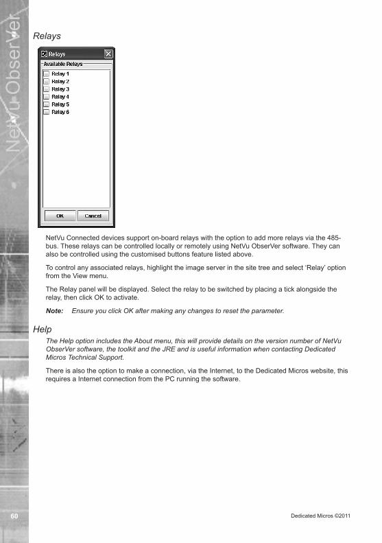
Dedicated Micros ©201160
Net
Vu O
bser
Ver
Relays
NetVu Connected devices support on-board relays with the option to add more relays via the 485-bus. These relays can be controlled locally or remotely using NetVu ObserVer software. They can also be controlled using the customised buttons feature listed above.
To control any associated relays, highlight the image server in the site tree and select ‘Relay’ option from the View menu.
The Relay panel will be displayed. Select the relay to be switched by placing a tick alongside the relay, then click OK to activate.
Note: Ensure you click OK after making any changes to reset the parameter.ENGLISH
HelpThe Help option includes the About menu, this will provide details on the version number of NetVu ObserVer software, the toolkit and the JRE and is useful information when contacting Dedicated Micros Technical Support.
There is also the option to make a connection, via the Internet, to the Dedicated Micros website, this requires a Internet connection from the PC running the software.

Dedicated Micros ©2011 61
Net
Vu O
bser
Ver
Google Earth IntegrationGoogle Earth software can be used in conjunction with NetVu ObserVer and a TransVu unit integrated with a GPS system. This will enable a vehicle’s position to be displayed and tracked via the Google Earth interface.
Note: The Google Earth software application can be downloaded from www.earth.google.comTo link Google Earth to NetVu ObserVer, open the Google Earth application and follow the instructions below:
Navigate to the ‘Add’ tool bar and select the ‘Network Link’ option. Select the ‘Refresh’ tab and complete the options as shown below:
1. Enter a connection name.2. Use the ‘Browse’ button to navigate to the ObserVer installation directory Program
Files\NetVu ObserVer. Locate the ObserVer.kml data file. The ObserVer.kml file contains downloaded data from the GPS unit linked to the connected TransVu.
3. Set the Time-Based Refresh option to: ‘Periodically‘ and ‘1 second’. 4. Click ‘OK’.
The link between Google Earth and NetVu ObserVer is now established. The Google Earth ‘Places’ option will include a reference to the newly created link:

Dedicated Micros ©201162
Net
Vu O
bser
Ver
PAN
A Double click on the link will result in a map being displayed. An icon will show the position of the TransVu device.
Please refer to the Google Earth website, www.earth.google.com; for details on map display options i.e. road layouts, terrain, borders etc.

Dedicated Micros ©2011 63
Net
Vu O
bser
Ver
Appendix ADisplay Options
There are a number of screen displays supported within the viewer, any of these can be selected from the drop down list
The following shows the screen displays along with the default camera positions when the associated display option is selected.
Single image 4 Way 9 Way
16 Way 4 (TL) plus 3 4 (TR) plus 3
4 (BL) plus 3 4 (BR) plus 3 8 Plus 2 (TL/TR)
8 Plus 2 (BL/BR) 8 Plus 2 (TL/BL) 8 Plus 2 (TR/BR)
12 Plus 1 (TL) 12 Plus 1 (TR) 12 Plus 1 (BL)
12 Plus 1 (BR) P in P (TL) P in P (TR)
P in P (BL) P in P (BR) 4 Way P in P (TL)
4 Way P in P (TR) 4 Way P in P (BL) 4 Way P in P (BR)
Twenty-five Way Thirty-six WayENGLISH
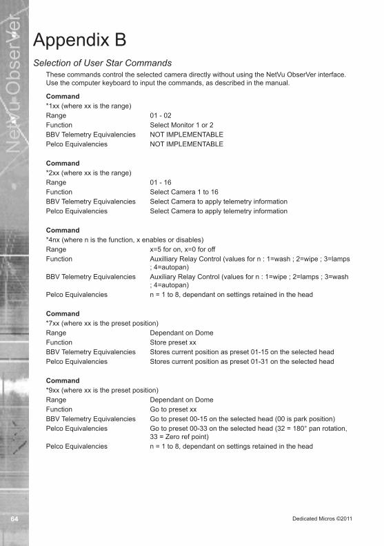
Dedicated Micros ©201164
Net
Vu O
bser
Ver
Appendix BSelection of User Star Commands
These commands control the selected camera directly without using the NetVu ObserVer interface. Use the computer keyboard to input the commands, as described in the manual.
Command*1xx (where xx is the range)Range 01 - 02Function Select Monitor 1 or 2BBV Telemetry Equivalencies NOT IMPLEMENTABLEPelco Equivalencies NOT IMPLEMENTABLE
Command*2xx (where xx is the range)Range 01 - 16Function Select Camera 1 to 16BBV Telemetry Equivalencies Select Camera to apply telemetry informationPelco Equivalencies Select Camera to apply telemetry information
Command*4nx (where n is the function, x enables or disables)Range x=5 for on, x=0 for offFunction Auxilliary Relay Control (values for n : 1=wash ; 2=wipe ; 3=lamps
; 4=autopan) BBV Telemetry Equivalencies Auxiliary Relay Control (values for n : 1=wipe ; 2=lamps ; 3=wash
; 4=autopan)Pelco Equivalencies n = 1 to 8, dependant on settings retained in the head
Command*7xx (where xx is the preset position)Range Dependant on DomeFunction Store preset xxBBV Telemetry Equivalencies Stores current position as preset 01-15 on the selected headPelco Equivalencies Stores current position as preset 01-31 on the selected head
Command*9xx (where xx is the preset position)Range Dependant on DomeFunction Go to preset xxBBV Telemetry Equivalencies Go to preset 00-15 on the selected head (00 is park position)Pelco Equivalencies Go to preset 00-33 on the selected head (32 = 180° pan rotation,
33 = Zero ref point)Pelco Equivalencies n = 1 to 8, dependant on settings retained in the head

Dedicated Micros ©2011 65
Net
Vu O
bser
Ver
Command*854xxx (where xxx is the setting)Range 000-001Function 000 = Patrol mode off, 001 = Patrol mode on BBV Telemetry Equivalencies ImplementedPelco Equivalencies Not Implemented
Command858xxx (where xxx is the setting)Range 000-001Function 000 = Turn Auto Pan off, 001 = Turn Auto Pan on BBV Telemetry Equivalencies Selects Autopan in frame 3, turned off my left or right movement,
or *858000Pelco Equivalencies Not Implemented
ENGLISH

Dedicated Micros ©201166
Net
Vu O
bser
Ver
Notes

Dedicated Micros ©2011 67
Net
Vu O
bser
Ver
IndexNetVu ObserVer ............................................................. 1User Guide ..................................................................... 1Introduction .................................................................... 3Features and Functions ................................................. 4How this Manual is Constructed .................................... 5The Manual is divided into five sections: ....................... 5Acronyms used in this document: .................................. 5NetVu ObserVer software can be accessed from: ......... 5Installing NetVu ObserVer Software ............................... 6Installing the JRE (Java runtime environment) file ......... 6Installing NetVu ObserVer application ............................ 6Configuring NetVu ObserVer Software .......................... 7Tools Menu ..................................................................... 7Behaviour ....................................................................... 7Network Options ............................................................ 9RVRC Options.............................................................. 10Appearance .................................................................. 11Update ........................................................................ 12Structuring the site tree ................................................ 13Adding a Folder ............................................................ 13Adding an Image Server to a Folder ............................ 14Advanced Image Server Properties Menu ................... 15Adding an Decoder to a Folder .................................... 17Configure Image Server via Browser ........................... 17View Menu ................................................................... 17Image Server Tree ....................................................... 17Activity Log, Embedded Data and Relays .................... 17Remote Events ............................................................ 17OpenStreetMap ............................................................ 18Interactive Map ............................................................ 18Keyboard ...................................................................... 18Dynamic Vehicle Data Displays ................................... 18Help Menu .................................................................... 20NetVu ObserVer Controls ............................................. 21Connecting to an Image Server ................................... 21Temporary Image Servers ............................................ 21Stored Image Servers .................................................. 21To connect to a stored image server: ........................... 21Existing Sitetree ........................................................... 22Disconnecting from an Image Server ........................... 22Disconnect From All ..................................................... 22Disconnect From an Image Server .............................. 22Disconnect From a Camera ......................................... 22Using the Interactive Map Feature ............................... 23Creating / ENGLISHEditing the Interactive Maps ........................ 23Adding a layer .............................................................. 24Adding Cameras .......................................................... 25Viewing the Interactive Maps ....................................... 25Common Controls ........................................................ 27Camera Selection ........................................................ 27To select a camera or cameras; ................................... 27Duplicating an Image ................................................... 27Swapping cameras in a segment. .............................. 27Display Mode ............................................................... 28Resolution Selection .................................................... 29Audio Control ............................................................... 29Freeze on a Single Image ............................................ 30Display Presets ............................................................ 30Live Mode Controls ...................................................... 31Live Mode .................................................................... 31Important Information ................................................... 33MPEG4/MJPEG ........................................................... 33Playback Mode Controls .............................................. 34
Record Options ............................................................ 34Last Recorded File ....................................................... 35Increase/Decrease Playback Speeds .......................... 35Mousekey Subfunctions ............................................... 35Go To Time and Date ................................................... 36Event List ..................................................................... 37Filter Events ................................................................. 39Activity .......................................................................... 40Activity Settings ............................................................ 40Camera Filter ............................................................... 40Please select the start and end dates .......................... 40Download Images ........................................................ 41To create an evidence CD ............................................ 41Filtered Download ....................................................... 41Raw Download ............................................................. 42Alarm Receiving Functionality ...................................... 43Configuring the System for Alarm Receiving ............... 43NetVu Connected Devices ........................................... 43Event Distribution Point Software ................................ 43To Install the EDP software .......................................... 44Specifications ............................................................... 44Installing the JRE (Java runtime environment) file ....... 44Installing the EDP application ...................................... 44Configuring the EDP Software ..................................... 44Administering User Accounts ....................................... 45To create a new User; .................................................. 45To edit a users details; ................................................. 46To change a Password; ................................................ 46To delete a User; .......................................................... 46Using the EDP from within NetVu ObserVer ................ 46To log into the EDP; ..................................................... 46Adding Temporary Image Server ................................. 48To add a temporary image server to the site tree: ....... 48Controlling Alarms ........................................................ 49Additional Alarm Information ........................................ 50EDP Report Generator ................................................. 51To access the Report Generator; ................................. 51Generating Reports ...................................................... 51Client Activity Report .................................................... 51Operator Performance Report ..................................... 52RVRC Activity Report ................................................... 52RVRC Fault Report ...................................................... 53RVRC Performance Report.......................................... 53Top 20 Sites Report ..................................................... 54Scheduled Reports ...................................................... 54Administration Function ............................................... 55Report Administration ................................................... 55Security Administration ................................................ 56General Administration ................................................. 56Preferences .................................................................. 56LogOff .......................................................................... 56Additional Functionality ................................................ 57Replay Server .............................................................. 57View Menu Additional Functions .................................. 58Embedded Data ........................................................... 58Embedded Text ............................................................ 59Activity log .................................................................... 59Relays .......................................................................... 60Help .............................................................................. 60Google Earth Integration .............................................. 61Appendix A ................................................................... 63Display Options ............................................................ 63Appendix B ................................................................... 64Selection of User Star Commands ............................... 64

Dedicated Micros France9-13 rue du Moulinet75013 Paris, France
Dedicated Micros SloveniaDelavska cesta 26,
4208 Sencure, Slovenia
Dedicated Micros BeneluxJoseph Chantraineplantsoen 1,
3070 Kortenberg, Belgium
Dedicated Micros USA.14434 Albemarle Point Place, Suite 100,
Chantilly, Virginia 20151 USA
Dedicated Micros USA.23456 Hawthorne Blvd.
Suite 100, Torrance, CA 90505, USA
Dedicated Micros, Australia PTY.5/3 Packard Avenue, Castle Hill,
NSW 2154, Australia
Dedicated Micros, Asia PTY16 New Industrial Road,
#03-03 Hudson Techno Centre,Singapore 536204
Dedicated Micros Middle EastBuilding 12, Suite 302, P.O. Box 500291, Dubai Internet
City, Dubai, United Arab Emirates
Dedicated Micros (Malta) Ltd.BLB017, Bulebel Industrial Estate,
Zejtun, ZTN2000, Malta
Dedicated Micros Ltd.1200 Daresbury Park, Daresbury,
Cheshire, WA4 4HS, UK
MI-I-NOB1827/E1-0