netaxis product overview. netaxis equipment description netaxis link configurations netaxis key...
TRANSCRIPT

NetAxisNetAxis Product Overview Product Overview

• NetAxis Equipment Description• NetAxis Link Configurations• NetAxis Key Features• Network Management Software
Agenda

NetAxisNetAxisEquipment DescriptionEquipment Description

Point-to-Point Microwave Radio SystemPoint-to-Point Microwave Radio System
NetAxis IDU4NetAxis IDU4
Enhanced Modular IDUEnhanced Modular IDU
NetAxis IDU2NetAxis IDU2
Compact IDUCompact IDU
ODU from 6 GHz to 38 GHz ODU from 6 GHz to 38 GHz
NetAxis Units

Max Throughput Capacity (per Modem) Up to 400 Mbit/s ( gross)
Traffic Interfaces
• E1• 10/100/1000 Ethernet
Modulation (user configurable through the NM) • QPSK /16QAM up to 256QAM
Channel Size Selection 7/14/28/56 MHz
Operating Frequency 6 GHz to 38 GHz
QoS
• per ETH Port• per VLAN• per p-bit• DSCP
Bridging Mode C-VLAN / S-VLAN
Topology 1+0,1+1,2+0,3+0,2+2,4+0,FD/SD/HSB
ATPC
ACM
XPIC
RLA
FEC
Loopback Capability
• ODU Front End• Line Interface
NMS
Features
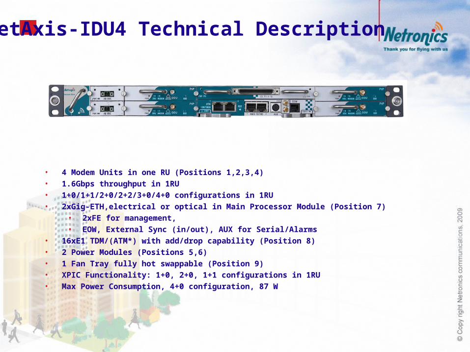
• 4 Modem Units in one RU (Positions 1,2,3,4)
• 1.6Gbps throughput in 1RU
• 1+0/1+1/2+0/2+2/3+0/4+0 configurations in 1RU
• 2xGig-ETH,electrical or optical in Main Processor Module (Position 7)
• 2xFE for management,
• EOW, External Sync (in/out), AUX for Serial/Alarms
• 16xE1 TDM/(ATM*) with add/drop capability (Position 8)
• 2 Power Modules (Positions 5,6)
• 1 Fan Tray fully hot swappable (Position 9)
• XPIC Functionality: 1+0, 2+0, 1+1 configurations in 1RU
• Max Power Consumption, 4+0 configuration, 87 W
NetAxis-IDU4 Technical Description

NetAxis-IDU2 Technical Description
• 2 Modem Units in one RU (Positions 1,2)
• 800 Mbps in 1RU
• 1+0/1+1/2+0 configurations in 1RU
• Main Control Module (Position 3)
• 1xGig-ETH, electrical or optical and 4xFE
• 8xE1 TDM/(ATM*)
• 2 FE for management,
• EOW, External Sync (in) AUX for Serial/Alarms
• Embedded Power Module
• Max Power Consumption, 2+0 configuration, 46 W
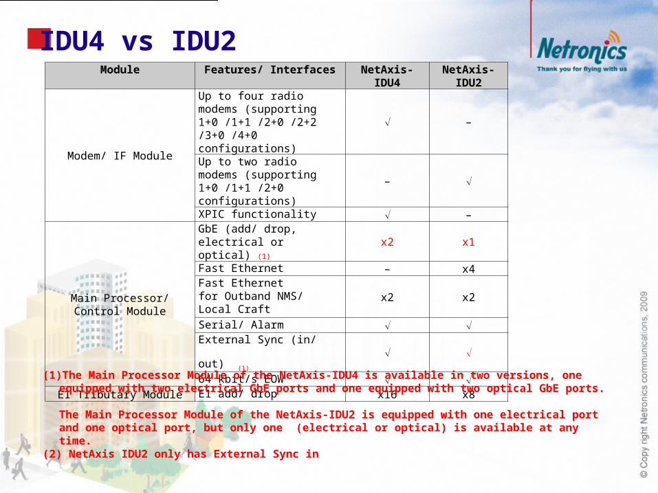
Module Features/ Interfaces NetAxis-IDU4 NetAxis-IDU2
Modem/ IF Module
Up to four radio modems (supporting 1+0 /1+1 /2+0 /2+2 /3+0 /4+0 configurations)
–
Up to two radio modems (supporting 1+0 /1+1 /2+0 configurations)
–
XPIC functionality –
Main Processor/ Control Module
GbE (add/ drop, electrical or optical) (1)
x2 x1
Fast Ethernet – x4Fast Ethernet for Outband NMS/ Local Craft
x2 x2
Serial/ Alarm
External Sync (in/ out) (1)
64 kbit/s EOW E1 Tributary Module E1 add/ drop x16 x8
IDU4 vs IDU2
(1) The Main Processor Module of the NetAxis-IDU4 is available in two versions, one equipped with two electrical GbE ports and one equipped with two optical GbE ports. The Main Processor Module of the NetAxis-IDU2 is equipped with one electrical port and one optical port, but only one (electrical or optical) is available at any time.
(2) NetAxis IDU2 only has External Sync in

NetAxis ODU Technical Description
Common ODU irrespective of channel BW and modulation
Supported frequencies: 6 to 38 GHz
Modulations QPSK to 256QAM
3.5MHz to 56MHz channel BW, SW defined
Outstanding radio performance
125.6dB System Gain for 4QAM and 7 MHz channel @ 6GHz
79.3dB System Gain for 256QAM and 56 MHz channel @ 38 GHz
Compact Design
Weight ~ 4Kg
Easy to install
Integrated Antennas & Protection
0.3, 0.6, 1.2, 1.8m Integrated Antennas
Symmetrical & Asymmetrical couplers
Power Consumption (Typical):
34 W (6,7,8 GHz), 26 W (11, 13 GHz), 23 W (15, 18, 23, 26,38 GHz)

Specification Description
Output Power Accuracy (max.)
± 1.5 dB (+25 C)
± 2 dB (-33 C to +55 C)
RSSI (RSL) Accuracy (typ.)
± 2 dB (+25 C)
± 3 dB (-33 C to +55 C)Max. Rx Level (No Damage)
10 dBm
Frequency Stability (max.)
± 7 ppm
Frequency Resolution
250 kHz
Input Voltage (*) -48 V (-40 V to –60 V)Safety EN 60950EMC ETSI EN 301489-1, ETSI EN 301489-4RoHS 2002/ 95/ EC
Specification DescriptionOperating Temperature
-33 C to +55 C (ETSI EN 300 V2.1.2, Class 4.1) / Operational at -50 C
Transportation & Storage Temperature
-40 C to +70 C (ETSI EN 300 V2.1.2, Class 2.3)
Relative Humidity (at 30 ºC)
90% to 100% (condensation), 93% (steady state)
(ETSI EN 300 V2.1.2, Class 4.1)
SpecificationODU-CF
6 /7/ 8 GHz 11/ 3/15/18/ 23/38 GHzDimensions (H x W x D) (mm)
250 x 247 x 106 237 x 247 x 89
Weight (kg) < 6 < 4
Input FlangeUBR70
UBR84 UBR120 UBR140 UBR220 UBR320
NetAxis ODU Specifications• Electrical
• Environmental
• Mechanical

NetAxisNetAxisLink ConfigurationsLink Configurations

Standard Configurations 1+0 Configuration
1+1 Configuration
Eth/E1Eth/E1NetAxis IDU2/IDU4NetAxis IDU2/IDU4
Eth/E1Eth/E1NetAxis IDU2/IDU4NetAxis IDU2/IDU4
Corporate Access
Corporate Access
Backbone Network
Backbone Network

Repeater Configuration 2+0 Configuration
2+2 Configuration
Cost effective by using single IDU per site.
Eth/E1Eth/E1
NetAxis IDU2/IDU4NetAxis IDU2/IDU4 NetAxis IDU2/IDU4
Repeater Configuration - Unprotected
Cost effective by using single IDU per site.
Eth/E1Eth/E1
Repeater Configuration - Protected
NetAxis IDU2/IDU4 NetAxis IDU4 NetAxis IDU2/IDU4
Backbone Network
Backbone Network
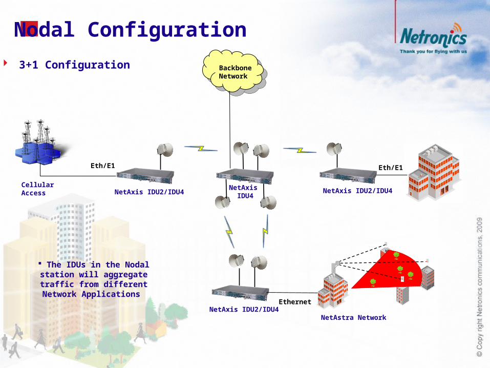
Nodal Configuration
The IDUs in the Nodal station will aggregate traffic from
different Network Applications
3+1 Configuration
Ethernet
Cellular Access
Eth/E1Eth/E1
NetAxis IDU2/IDU4NetAxis
IDU4NetAxis IDU2/IDU4
NetAxis IDU2/IDU4NetAstra Network
Backbone Network

Nodal Configuration 4+0 Configuration
The IDUs in the Nodal station will aggregate traffic
from different Network Applications
Ethernet
Cellular Access
Eth/E1Eth/E1
NetAxis IDU2/IDU4NetAxis
IDU4NetAxis IDU2/IDU4
NetAxis IDU2/IDU4NetAstra Network
Backbone Network
Cellular Access
Eth/E1
NetAxis IDU2/IDU4

Ring Configuration
Protection and recovery switching within 50 ms Efficient bandwidth utilization of ring traffic Automatic reversion mechanism upon fault recovery Frame duplication and reorder prevention mechanisms Loop prevention mechanisms Use of different timers (WTR timer, Hold-off timers) to avoid race conditions and unnecessary switching operations Ring Protection with XPIC functionality (only with NetAxis-IDU4)
NetAxis IDU2/IDU4
NetAxis IDU2/IDU4NetAxis
IDU2/IDU4
NetAxis IDU2/IDU4
NetAxis IDU2/IDU4
Backbone Network
Cellular Access
NetAxis IDU2/IDU4
Eth/E1
Eth/E1

NetAxis Deployment Examples
• Mobile Backhaul

NetAxis Deployment Examples
WiMAX Backhaul
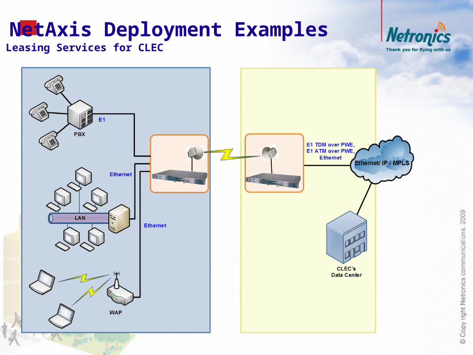
NetAxis Deployment Examples Leasing Services for CLEC

NetAxis Deployment Examples Resilient Network infrastructures

NetAxisNetAxisKey FeaturesKey Features

PDH / SDHPDH / SDHngSDHngSDH
2G3G
3G/HSPAWiMAX
LTETDM
Ba
sed
Pack
et
Base
d
Eth / PWE3 / MPLSEth / PWE3 / MPLS
2G3G
3G/HSPAWiMAX
LTE
Hyb
rid
PDH / SDHPDH / SDHngSDHngSDH
2G3G
3G/HSPAWiMAX
LTEEth / MPLSEth / MPLS
NetAxis All IP Evolution

NetAxis features a powerful network processor for advanced ETH functionality Advanced traffic handling and QoS per ETH port/VLAN/pbit
IEEE 802.1Q and 802.1p (CoS) IEEE 802.1ad (QinQ - Provider bridging) DSCP mapping to p-bits 8 QoS Priority Queues
ETH Ring (G.8032) and IEEE 802.1w (RSTP) Pseudowires (Circuit Emulation over ETH) based on MEF 8
Structure agnostic emulation Structure aware emulation (nx64kbps) for Abis optimization
ATM PWE (RFC4717) (Roadmap) Synchronization:
Based on E1 Synchronous ETH IEEE 1588v2
NetAxis Network Functionality
Ensuring proper QoS of various traffic flows

NetAxis ETH Functionality
BTS(E1 TDM)
Bridge
Bridge
NodeB(ETH)
Bridge
NodeB(E1 ATM)
Bridge
NodeB(ETH)
Bridge
NodeB(ETH)
Bridge
C-VLAN = xC-VLAN = z
C-VLAN = y
Bridge
C-VLAN = k C-VLAN = l
Bridge
C-VLANs = k,lC-VLANs = x,y,z
Metro EthernetNetwork (MEN)
C-VLANs = x,y,z,k,l
ETH Switch(Q-in-Q)
RNC
C-VLANs =x,y,z,k,l
BSC C-VLAN
Used solely for Network backhaul applicationsAll L2 ports within the wireless network are programmed for C-VLAN modeL2 ports can accept :
Untagged Ethernet frames Single tagged Ethernet frames.

NetAxis ETH Functionality
Used for concurrent Network backhaul applicationsAll L2 ports within the wireless network are programmed for S-VLAN provider modeL2 ports can accept the following Ethernet frames:
Untagged Ethernet frames Single tagged Ethernet frames.Double tagged Ethernet frames
Bridge
NodeB #2(C-VLAN = 2)
Bridge Bridge
NodeB #1(C-VLAN = 1)
Bridge
NodeB #3(C-VLAN = 4)
Bridge
S-VLAN = 100
S-VLANs = 100, 101, 103
Metro EthernetNetwork – MEN
(Q-in-Q)
RNC
C-VLANs = 1,2,4
S-VLAN = 101
S-VLAN = 103
Bridge
Business B #1VLAN Switch
(C-VLANs = 2,8,4)
S-VLAN = 103
S-VLAN = 102
S-VLAN = 104
S-VLANs = 102, 103, 104
S-VLANs = 100,101,102, 104
Bridge
Bridge Bridge
ProviderQ-in-Q Switch
ProviderQ-in-Q Switch
ProviderQ-in-QSwitch
S-VLAN transparent L2 port
S-VLAN provider L2 port
S-VLANs =100,101,102
S-VLANs = 104
C-VLANs = 2,8,4
Business A #1VLAN Switch
(C-VLANs = 2,8,16)
Business A #2VLAN Switch
(C-VLANs = 2,8,16)
Business B #2VLAN Switch
(C-VLANs = 2,8,4)
S-VLAN

NetAxis Adaptive Coding & Modulation (ACM)
256QAM
QPSK
16QAM
32QAM
64QAM
128QAM
256QAM
Capacity(Mbit/s)
Time
99.90%
99.95%
99.99%
99.995%
99.999%GSM/R99
256QAM
16QAM
32QAM
64QAM
128QAM
QPSK99.999%
HSDPA
High-Priority Traffic (Voice, Real-Time Video)
Low-Priority Traffic (Internet services, etc.)
Ensuring maximum bandwidth under all weather conditions
With QoS guaranteed critical services all the time
Increasing capacity
Extending reach with lower availability
ACM with QoS

RRC: ACM is optimally combined with Automatic Transmit Power Control (ATPC) RRC achieves the perfect balance according to user selection between
Maximizing at any time the available link capacity Minimizing at any time interference
ATPC operational modes ATPC emitting the maximum available power per ACM mode ATPC emitting the optimum power per ACM mode for the remote receiver Manual power selection is also possible
RRC algorithm for each link direction is controlled by the transmitter CPU independently Communication channel will exchange info on remote RX level, BER figures, C/N
Maximum Bandwidth with minimum power consumption
NetAxis Adaptive Coding & Modulation (ACM) Radio Resource Control (RRC)
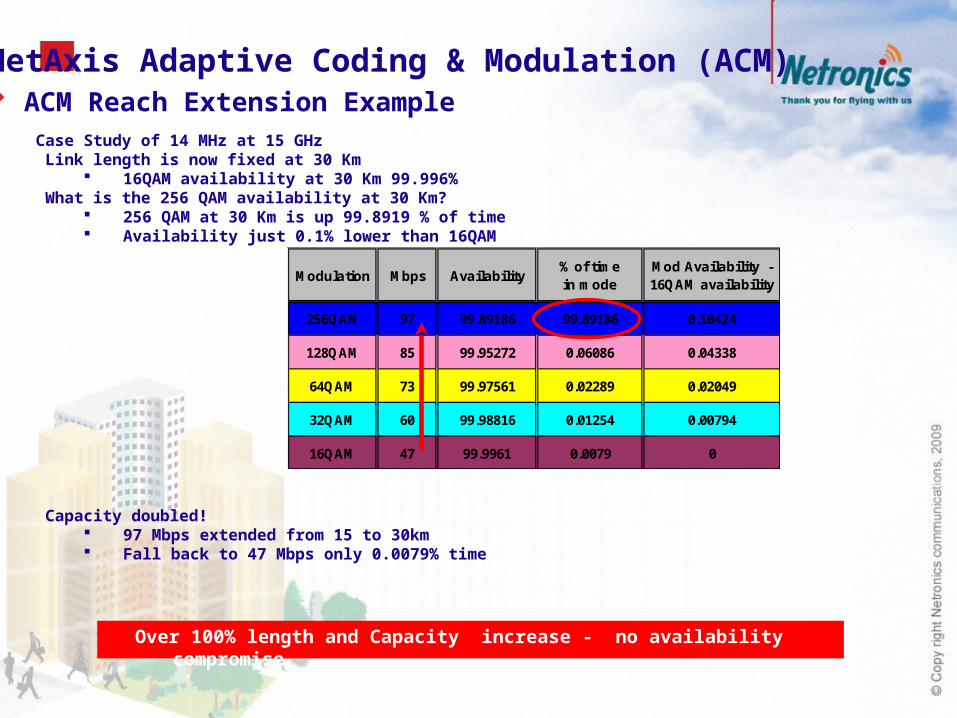
NetAxis Adaptive Coding & Modulation (ACM) ACM Reach Extension ExampleCase Study of 14 MHz at 15 GHz Link length is now fixed at 30 Km
16QAM availability at 30 Km 99.996% What is the 256 QAM availability at 30 Km?
256 QAM at 30 Km is up 99.8919 % of time Availability just 0.1% lower than 16QAM
Capacity doubled! 97 Mbps extended from 15 to 30km Fall back to 47 Mbps only 0.0079% time
Modulation Mbps Availability% of time in mode
Mod Availability - 16QAM availability
256QAM 97 99.89186 99.89186 0.10424
128QAM 85 99.95272 0.06086 0.04338
64QAM 73 99.97561 0.02289 0.02049
32QAM 60 99.98816 0.01254 0.00794
16QAM 47 99.9961 0.0079 0
Over 100% length and Capacity increase - no availability compromise

Max. Gain (Robustness)
Normal (Optimized
Robustness/Capacity)
Max. Capacity
(Throughput)
Symbol Rate Min. Intermediate Max.FEC overhead Max. Intermediate Min.
Adaptive modulation
switching margins Max. Intermediate Min.
Radio Maximum transmit power applications .
Normal system gain and capacity applications
Maximum capacity applications
Sensitivity Max., due to the highest FEC overhead).
Normal, due to the intermediate FEC overhead.
Min., due to the lowest FEC overhead.
Immunity in variable channel
conditions Increased Normal Smaller
NetAxis System Configuration Scenarios
Modem Profiles

NetAxis System Configuration Scenarios (Example)
Case Study: 15 GHz, Bandwidth 14 MHz, 1+0, Location: Athens -Greece, Antenna type 1.2m SP UHP, Polarization V, R001 Rain Rate Data Source ITU-R Rec. P.837-5 (47.55 mm/hr), Method of Calculation ITU-R Rec. P530-12
Performance Target: Minimum Availability 99.995% Operational mode ranges per modulation for min 99.995% availability
0 10 20 30 40 50
Range (Km)
256QAM
128QAM
64QAM
32QAM
16QAM
4QAM_0.9
4QAM_0.75
+5Km
Extend link span by 5 Km with no link availability deterioration
Flexible Operational Modes

Modulation
Value per Channel Size (Mbit/s)
56 MHz 28 MHz 14 MHz 7 MHz
256 QAM 357.88 195.01 96.81 47.70
128 QAM 315.61 171.93 85.28 42.05
64 QAM 270.49 147.29 73.01 35.87
32 QAM 219.85 119.62 59.46 28.81
16 QAM 175.75 95.54 47.23 22.98
8 PSK 115.12 62.42 30.67 14.80
4 QAM (Low FEC) 87.46 47.31 23.16 11.03
4 QAM (High FEC) 69.76 37.65 18.31 8.64
NetAxis System Configuration Scenarios (Example)
Maximum Capacity Configuration
Throughput

NetAxis XPIC & Radio Link Aggregation (RLA) –(Roadmap)
XPIC doubles air throughput over same Channel Bandwidth E.g., 1x28 MHz, XPIC, max 375 Mbps net traffic 1+1 XPIC in 1RU unit
RLA combines 2 or more air links into one logical link E.g., 2+0 can achieve gross capacity 800 Mbps Link speeds may be different
Benefits: Higher total capacity of logical link Load balancing among air links Increased availability: When a link fails its traffic will be forwarded to the other link and in case of congestion priority will be given to the high-priority ETH frames
Combining RLA and XPIC enables the most efficient and resilient air link utilization
XPIC saves CAPEX - 100% less frequency bandwidth allocation

NetAxis Statistical Multiplexing
Statistical Multiplexing
of packet traffic at Aggregation Point
Reduced bandwidth requirement in the aggregation / core network
BSC/RNCTransport Network
2G/3G Networ
k
2G/3G
2G/3G
More Connections Enabled per Link Lower Cost per Connection

Ring Configuration using a single unit with 2/4 radios Native ETH Ring Protection (G.8032)
Protection and recovery switching within 50 ms Ring Protection with XPIC functionality – just one NetAxis-IDU4 per site
NetAxis Ring Protection
NetAxis IDU2/IDU4
NetAxis IDU2/IDU4
NetAxis IDU2/IDU4
NetAxis IDU2/IDU4
NetAxis IDU2/IDU4
Backbone Network
Cellular Access
NetAxis IDU2/IDU4
Eth/E1
Eth/E1

Direct correlation between interface and transmission
Additional Ethernet switches overlaying mandatory TDM matrix
No possibility to differentiate TDM services with different QoS requirements
No aggregation, no overbooking on services using TDM connectivity.
Inefficient solution in case of full Ethernet traffic (WiMAX, LTE); could require external switches
MW Hybrid
Service-oriented transmission with no correlation between interface and transmission
Dynamic capacity allocation between TDM, ATM and ETH services
Services are treated according to their QoS requirements even on TDM
Service Overbooking in a multi-technology environment: TDM, ATM, Ethernet
All services over a common layer, any kind of traffic can share a common radio pipe. Radio bandwidth is utilized at 100%
NetAxis
Less cost per bit - Ability to overbook available capacity
NetAxis Advantages over Hybrid Radios

NetAxis NetAxis Network Management SoftwareNetwork Management Software

NetAxis ME
Selecting the Element Select the IP
1. Link Summary Tab In the Tabular Pane click the Link Summary tab
NOTENetAxis IDU4 will have info for 4 Modems
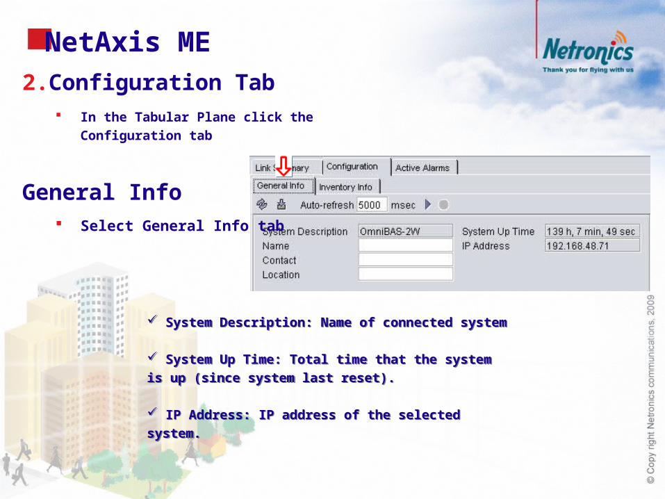
2. Configuration Tab In the Tabular Plane click the
Configuration tab
General Info Select General Info tab
System Description: Name of connected system
System Up Time: Total time that the system is up (since
system last reset).
IP Address: IP address of the selected system.
System Description: Name of connected system
System Up Time: Total time that the system is up (since
system last reset).
IP Address: IP address of the selected system.
NetAxis ME

Inventory Information Select Inventory Info tab
NetAxis ME

NetAxis Control Card
Selecting the Control Card Select the card (don’t click on ports)
1. Configuration Tab
In the Tabular Plane click the Configuration tab
Temperature Info
Select Temperature Info tab
Through the Current Temperature field, you can view the current temperature inside the Control card.
In case you want to change the high temperature threshold of the Control Card, type the new one in the High Temperature Threshold text box.
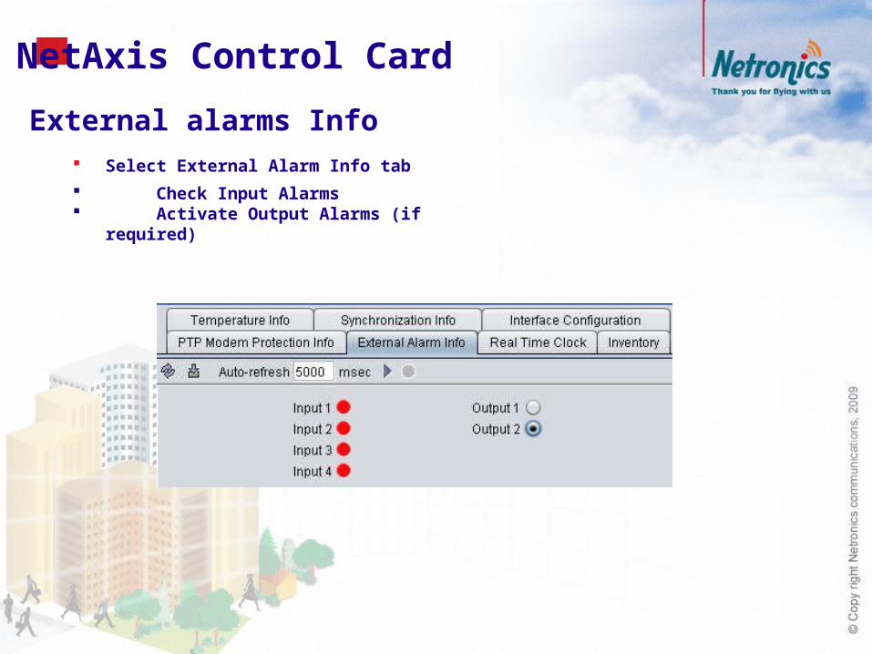
External alarms Info Select External Alarm Info tab
Check Input Alarms Activate Output Alarms (if required)
NetAxis Control Card

Inventory Select the Inventory tab
Check Controllers info
Interface Configuration Select the Interface
Configuration tab.
Check the PWE Src MAC
Address.
NetAxis Control Card
NetAxis Control Card
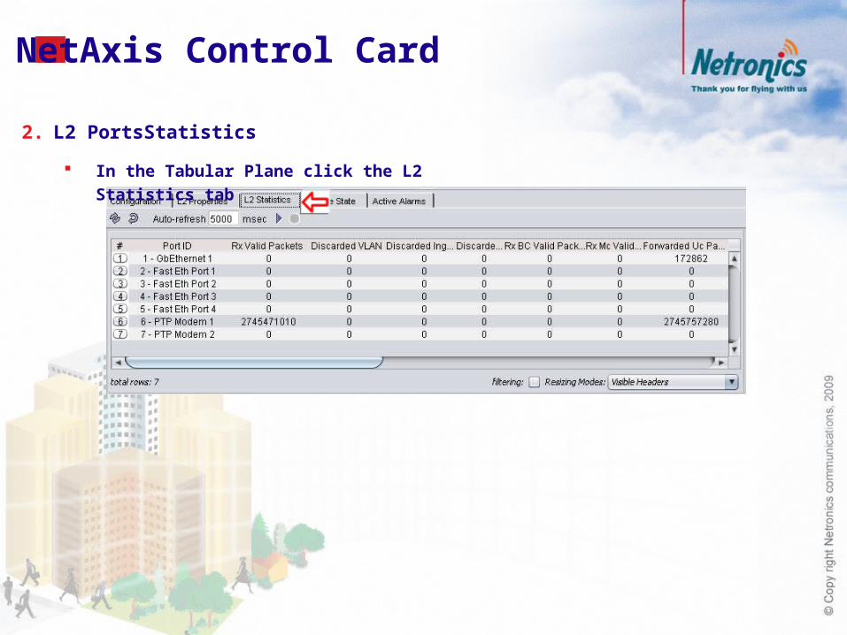
2. L2 PortsStatistics
In the Tabular Plane click the L2 Statistics tab

NetAxis Modem Card
Modem Card Select the Modem Card
1. In the Tabular Pane click the Configuration tab
Inventory Info Select Inventory Info tab
Check Modem Info

NetAxis Modem CardStatus
Select Status tab
Check Modems Status

Fan Tray Info (Only with IDU2) Select Fan Tray Info tab
Check Fan Status
NetAxis Modem Card
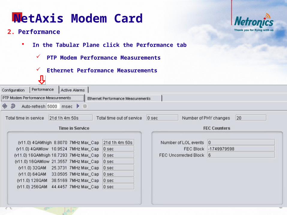
2. Performance
In the Tabular Plane click the Performance tab
PTP Modem Performance Measurements
Ethernet Performance Measurements
NetAxis Modem Card

Select Ethernet Performance Measurements tab
Tx (Air to Net)
NetAxis Modem Card

Rx (Net to Air)
NetAxis Modem Card

Rate
To monitor the bytes rate (in Mbps) in the Rx and Tx
directions of the modem
NetAxis Modem Card
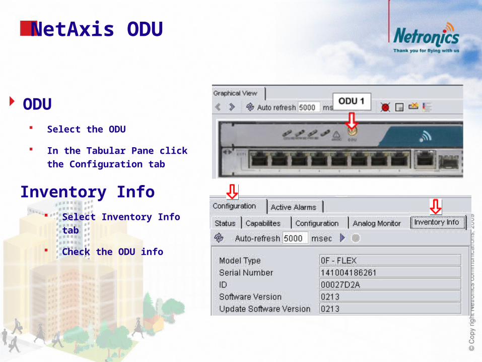
Inventory Info Select Inventory Info tab
Check the ODU info
NetAxis ODU
ODU Select the ODU
In the Tabular Pane click the
Configuration tab

Status Select Status tab
Check the ODU Status
NetAxis ODU

Analog Monitor Select Analog Monitor tab
Check the ODUs Analog real
time measurements.
NetAxis ODU

NetAxis ODU
Capabilities Select Capabilities tab
Check the selected ODUs
capabilities.

NetAxis ETH Ports ETH Port
Select one of the ETH Ports
1. In the Tabular Pane click the Configuration tab
System will detect Type:
Electrical
Optical
Check Port Status

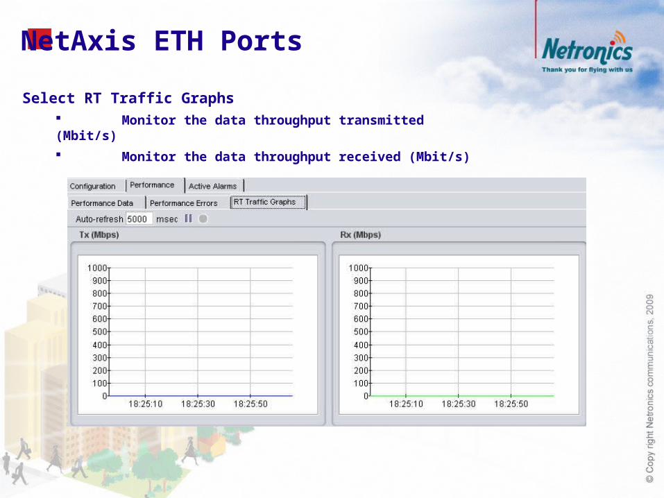
2. Performance (Only GbE)
In the Tabular Plane click the Performance tab
Performance Data
Performance Errors
RT Traffic Graphs
NetAxis ETH Ports
Select Performance Data tab

NetAxis ETH PortsSelect Performance Errors tab
NetAxis ETH Ports
Select RT Traffic Graphs Monitor the data throughput transmitted (Mbit/s)
Monitor the data throughput received (Mbit/s)

NetAxis E1 Ports E1 Port
Select one of the E1 Ports
In the Tabular Pane click the
Configuration tab
E1Type:
Unstructured
Structured
• Double Frame
• Multiframe (CRC)

NetAxis All E1 Lines Selecting the Control Card
Select the card (don’t click on ports)
1. E1 Line State
In the Tabular Plane click the E1 Line State tab
Check the Status of all E1

NetAxis All E1 Lines2. Performance Measurment
In the Tabular Plane click the L2 Properties tab
Click the TDM tab
Select E1
Right Click & Select Performance Measurements

NetAxis All E1 Lines
The Performance Measurements window appears, displaying the statistics for the selected PWE TDM connection.

NetAxis Active Alarms
Active Alarms Properties In the Tabular Plane of each module click the Active Alarms tab

NetAxis Real Time Events
Real Time Events In the NetAxis Node Manager window, click the Real Time Events perspective

Service Provisioning (examples)
Create the VLAN you want in the local NetAxis ME (e.g. VLAN with ID=20).
Create a PWE TDM connection within the selected NetAxis ME. [1].
Associate the VLAN with a wireless L2 port of the local NetAxis ME (e.g. PTP Modem 2) [2].
Create the same VLAN in the remote NetAxis ME of the link.
Create a PWE TDM connection within the selected remote NetAxis ME. [3].
Associate the VLAN with a wireless L2 port of the remote NetAxis ME (e.g. PTP Modem 2) [4].
PWE TDM service provisioning

Thank youThank you
www.netronics-networks.comwww.netronics-networks.com