netaquatm user manual roslen eco-networking productscache.smarthome.com/manuals/31530-man.pdf ·...
TRANSCRIPT

netAquaTM USER MANUAL Roslen Eco-Networking Products
v1.0.03 © 2014 by Roslen Eco-Networking Products. All rights reserved Page 1 of 59
Roslen netAQUATM 9D USER MANUAL

netAquaTM USER MANUAL Roslen Eco-Networking Products
v1.0.03 © 2014 by Roslen Eco-Networking Products. All rights reserved Page 2 of 59
User Notes…

netAquaTM USER MANUAL Roslen Eco-Networking Products
v1.0.03 © 2014 by Roslen Eco-Networking Products. All rights reserved Page 3 of 59
TABLE OF CONTENTS
1. NETAQUATM 9D NETWORK- ENABLED IRRIGATION CONTROLLER .............. 9
1.1. Terminology 9
2. HOW TO’S ........................................................................................................... 10
2.1. Connect the netAQUA to Power 10 2.1.1. Connecting the netAQUA Using the Supplied Transformer 10 2.1.2. Connecting the netAQUA to an Existing 24 VAC Source 10
2.2. Connect the netAQUA to Your Computer Network 11 2.2.1. Device IP Address on the LCD 13 2.2.2. Type the Name of Your netAQUA into the Browser Address Bar 15 2.2.3. Use the netFINDER Application 16 2.2.4. Connect the netAQUA to your WiFi Network 16
2.3. Connect the netAQUA to the Irrigation Valves 19 2.4. Program a Basic Watering Plan 20 2.5. Manually Launch Watering 23 2.6. Access the netAQUA from Outside 24
2.6.1. Setting up Port Forwarding 24 2.6.2. Setting-up Access Security on the netAQUA 26 2.6.3. Setting-up a Static IP Address on the netAQUA 26 2.6.4. Setting-up a DDNS Service 28 2.6.5. A Summary of Accessing Your netAQUA from the Internet 29
2.7. Access the netAQUA Directly 29 2.8. Update the Software in the netAQUA 33 2.9. Manually Start a Zone Using the LCD/Pushbutton Interface 35
3. FUNCTIONS AND FEATURES ............................................................................ 37
3.1. Valve Solenoid Outputs Control 37 3.2. Timer Control 37 3.3. Manual Override of Timer Control 37 3.4. Manual Watering Disable 37 3.5. LEDs 37
3.5.1. Status LED 37 3.5.1.1. Status Indication 37
3.5.2. WiFi LED 38 3.6. Monitoring 38
3.6.1. Local Temperature 38 3.6.2. Local Rainfall 38 3.6.3. Internet Temperature and Humidity 38 3.6.4. Water Flow 38 3.6.5. Threshold Response 39 3.6.6. Monitoring Input Threshold Crossing Notification 39
3.7. Ethernet Interfaces 39 3.8. netAQUA Browser Interface 39
3.8.1. Tabbed Navigation 40 3.8.1.1. Status Page 40 3.8.1.2. Watering Settings Page 41
3.8.1.2.1. Global Watering Settings ........................................................................................... 41 3.8.1.2.2. Watering Cycles ........................................................................................................ 42 3.8.1.2.3. Manual Operation ...................................................................................................... 42
3.8.1.2.3.1. Abort .................................................................................................................... 42

netAquaTM USER MANUAL Roslen Eco-Networking Products
v1.0.03 © 2014 by Roslen Eco-Networking Products. All rights reserved Page 4 of 59
3.8.1.3. System Settings Page 42 3.8.1.4. Software Page 44
3.8.2. Accessibility 44 3.9. LCD/Pushbutton Interface 44
3.9.1. Basic Pushbutton Operation 44 3.9.1.1. LCD Wakeup 45
3.9.2. Basic Programming Operation 45 3.9.2.1. Special Case – Global Watering Enable/Disable 45
3.9.3. Top Level LCD Pages 45 3.9.3.1. Main Control Page 45 3.9.3.2. Watering Status Page 46 3.9.3.3. System Status Page 46 3.9.3.4. Automatic Watering Settings Page 47 3.9.3.5. Manual Watering Operation Page 47
3.9.4. Watering Cycles LCD Pages 48 3.9.4.1. Watering Cycles Programming 48 3.9.4.2. Watering Cycles Help in Status Mode 49 3.9.4.3. Watering Cycles Help in Programming Mode 49
3.9.5. Manual Operation Control Level LCD Page 50 3.9.5.1. Manual Watering Programming 51 3.9.5.2. Manual Watering Help in Status Mode 51 3.9.5.3. Manual Watering Help in Programming Mode 51
3.9.6. User Programming Details 52 3.9.6.1. Special Case – Global Watering Enable/Disable 52
3.10. Programmable Field Details for Watering 52 3.10.1. Programmable Fields for Automatic Watering Cycles 52
3.10.1.1. Watering Cycle Enable 53 3.10.1.2. Watering Cycle Start Time 53 3.10.1.3. Watering Frequency 53
3.10.1.3.1. Set Days of Week .................................................................................................... 53 3.10.1.4. Zone Duration 53
3.10.2. Programmable Fields for Manual Watering Operation Control 53 3.10.3. Programming Conflicts 54
3.11. Factory Default Configuration 54 3.11.1. Reset to Factory Default 54
3.12. System Restart 55 3.13. Operation Recovery without Current Time Data 55 3.14. Freezing Temperature Protection 55 3.15. No Internet Access 55 3.16. Browser Interface/LCD Differences 55
4. PHYSICAL INTERFACES .................................................................................... 56
4.1. AC Input 56 4.2. Valve Solenoid Control Outlets 56 4.3. Ethernet 56 4.4. WiFi 56 4.5. Expansion Module 56 4.6. Power LED 56 4.7. WiFi LED 56 4.8. Pushbutton Switches 56 4.9. Local Rainfall Sensor 56 4.10. Local Temperature Sensor 56 4.11. Water Flow Sensor 56 4.12. EM Power 56

netAquaTM USER MANUAL Roslen Eco-Networking Products
v1.0.03 © 2014 by Roslen Eco-Networking Products. All rights reserved Page 5 of 59
5. TROUBLESHOOTING GUIDE ............................................................................. 57
5.1. WiFi connection problem 57 5.2. Technical Support 57
6. SPECIFICATIONS ................................................................................................ 58
6.1. Specifications table 58
7. FCC NOTICE ........................................................................................................ 59

netAquaTM USER MANUAL Roslen Eco-Networking Products
v1.0.03 © 2014 by Roslen Eco-Networking Products. All rights reserved Page 6 of 59
TABLE OF FIGURES Figure 1: Power Cable Connection to Transformer ................................................................................... 10
Figure 2: Ethernet Cable Connection to the netAQUA .............................................................................. 11
Figure 3: Webbed Grommet for Cable Entry ............................................................................................. 12
Figure 4: Ethernet LAN Ports on Back of Router ....................................................................................... 12
Figure 5: Status LED (top), WiFi LED (bottom), Control Pushbuttons ....................................................... 13
Figure 6: LED and Control Pushbutton Labelling ....................................................................................... 13
Figure 7: System Status Page ................................................................................................................... 14
Figure 8: Browser Interface Status Page ................................................................................................... 14
Figure 9: Browser Interface Access Through NetBIOS ............................................................................. 15
Figure 10: Browser Interface Access Through NetBIOS with Chrome Browser ........................................ 15
Figure 11: Network Settings in Browser Interface ..................................................................................... 17
Figure 12: WiFi Interface Settings .............................................................................................................. 18
Figure 13: Webbed Grommet for Cable Entry ........................................................................................... 19
Figure 14: Irrigation Zones Wired at the netAQUA .................................................................................... 20
Figure 15: Master Valve Enable ................................................................................................................. 20
Figure 16: Main Watering Plan Settings .................................................................................................... 21
Figure 17: Cycle Programming .................................................................................................................. 22
Figure 18: Status of Upcoming Watering ................................................................................................... 22
Figure 19: Manual Watering Options ......................................................................................................... 23
Figure 20: Netgear WNR3500L Port Forwarding Set-up Example ............................................................ 25
Figure 21: Security Settings ....................................................................................................................... 26
Figure 22: Security Credentials Entry ........................................................................................................ 26
Figure 23: Static IP Address Configuration ................................................................................................ 27
Figure 24: Router DHCP Range ................................................................................................................ 28
Figure 25: System Status LCD Screen with Default IP Address ............................................................... 30
Figure 26: Control Panel ............................................................................................................................ 30
Figure 27: Network and Internet Settings Group ....................................................................................... 31
Figure 28: Network Connections ................................................................................................................ 31
Figure 29: Network Connections Listing .................................................................................................... 31
Figure 30: Select Properties for IPv4 ......................................................................................................... 32
Figure 31: Manual IP Address Settings ..................................................................................................... 33
Figure 32: Software Tab ............................................................................................................................. 34
Figure 33: Update File Selection ................................................................................................................ 34
Figure 34: Main Control Page .................................................................................................................... 46
Figure 35: Watering Status Page ............................................................................................................... 46
Figure 36: System Status Page ................................................................................................................. 47

netAquaTM USER MANUAL Roslen Eco-Networking Products
v1.0.03 © 2014 by Roslen Eco-Networking Products. All rights reserved Page 7 of 59
Figure 37: Automatic Watering Settings Page ........................................................................................... 47
Figure 38: Manual Watering Operation Page ............................................................................................ 48
Figure 39: Watering Cycle .......................................................................................................................... 48
Figure 40: Watering Cycle Days of the Week Programming ..................................................................... 49
Figure 41: Watering Cycle Status Mode Help Page .................................................................................. 49
Figure 42: Watering Cycle Programming Mode Help Page ....................................................................... 50
Figure 43: Manual Operation Control Page ............................................................................................... 50
Figure 44: Manual Watering Operation Control Status Help Page ............................................................ 51
Figure 45: Manual Watering Operation Control Programming Mode Help Page ...................................... 52

netAquaTM USER MANUAL Roslen Eco-Networking Products
v1.0.03 © 2014 by Roslen Eco-Networking Products. All rights reserved Page 8 of 59
TABLE OF TABLES Table 1: Valve Output Current Carrying Requirements ............................................................................. 37
Table 2: Browser Interface/LCD Differences ............................................................................................. 55
Table 3: Specifications ............................................................................................................................... 58

netAquaTM USER MANUAL Roslen Eco-Networking Products
v1.0.03 © 2014 by Roslen Eco-Networking Products. All rights reserved Page 9 of 59
1. netAQUATM 9D NETWORK- ENABLED IRRIGATION CONTROLLER
Thank you for your purchase of the netAQUA network-enabled irrigation controller. We are confident that the netAQUA will fulfill your automated watering needs, and we welcome your comments and feedback at any time.
This document is divided into the following sections:
• How To’s: In this section, the main processes that you may encounter while using the netAQUA are described in step-by-step instructions.
• Functions and Features: In this section, functions and features of the netAQUA are described in specific detail.
• Troubleshooting: In this section, most common troubleshooting tasks are described. • Specifications: The Specifications section outlines the key characteristics of the netAQUA
Please check the our website (roslen.com) for any updates to this manual.
The netAQUA 9D is available in two versions, with and without the WiFi networking interface. Other than the provision of the additional networking interface, the netAQUA 9D WIFI is functionally identical to the netAQUA 9D. Sections of this document that pertain to the WiFi interface are not applicable to the netAQUA 9D.
1.1. Terminology A few words about terminology used in this document. The netAQUA Browser Interface refers to the netAQUA point and click user interface that appears in a browser (Internet Explorer, Firefox, Chrome, Safari, etc.) on your computer, notepad or smartphone . The term tab refers to the top-level Browser Interface organization; the tabs, located along the top of the Browser Interface page shown in the browser, select among the four main topics:
• Status, where the current conditions of the netAQUA are shown • Watering Settings, where all watering plan programming takes place • System Settings, where all system configuration options are located • Software, where a new software file can be selected for update.
The term section as used in this manual refers to the menu sections listed along the left side of each Browser Interface page. Clicking one of these links will move the page down to the appropriate area, or will bring up different, but related, content.
The term group as used in this manual refers to content outlined in rectangles, along the middle column of information on each Browser Interface page. Each group includes a topical heading at the top of the rectangle.

netAquaTM USER MANUAL Roslen Eco-Networking Products
v1.0.03 © 2014 by Roslen Eco-Networking Products. All rights reserved Page 10 of 59
2. HOW TO’S The How To’s section of the manual describes the most frequent tasks that you might do while interacting with the netAQUA. It is designed to get you started easily and quickly in using the device. So, let’s begin…
2.1. Connect the netAQUA to Power Depending on your purchase option, your netAQUA may include a transformer, and, if not, you will need to connect it to an existing 24 VAC source.
2.1.1. Connecting the netAQUA Using the Supplied Transformer The netAQUA power cable has three leads:
• White: 24 VAC input • Black: 24 VAC input • Green: Ground
The green lead must be connected to the center terminal on the transformer. The white and black leads need to be connected to the outer terminals; it does not matter which color AC lead is connected to which one of the outer terminals.
INSERT PICTURE OF THE CONNECTED TRANSFORMER
To power up the netAQUA, insert the transformer to a 110 VAC wall outlet.
2.1.2. Connecting the netAQUA to an Existing 24 VAC Source If you are replacing an older irrigation controller with the netAQUA, you may already have a source of 24 VAC power available. In this case, you can connect the netAQUA directly to that source, without the need for the transformer. The white 24 VAC lead should connect to a terminal marked as 24 VAC on your existing source, and the black 24 VAC lead should connect to a second terminal marked as 24 VAC. The green lead, GND needs to connect to a ground terminal in your existing installation.
Figure 1: Power Cable Connection to Transformer
As soon as you connect the power leads to the power and ground terminals of your existing installation, the netAQUA will power up.

netAquaTM USER MANUAL Roslen Eco-Networking Products
v1.0.03 © 2014 by Roslen Eco-Networking Products. All rights reserved Page 11 of 59
2.2. Connect the netAQUA to Your Computer Network The netAQUA is a network-enabled device, so although the fundamental watering plan programming steps can be accomplished using the local LCD/pushbutton interface, you will access a host of additional features and configuration options by opening the netAQUA Browser Interface in your favorite web browser. To do this, you’ll need to connect the netAQUA to your computer network.
Also, if you wish to use the netAQUA with your WiFi network (netAQUA 9D WIFI only), you’ll need to first connect to the network using the cable interface in order to configure the device to work on your WiFi network.
The best way to do that is to locate the netAQUA near your router or near a network switch. This will allow you to easily connect the device to your wired network for further configuration. If you’re going to do this step only to configure the WiFi interface, or some other part of the wired network interface, it’s simplest just to take the cover off the netAQUA and place one end of the included Ethernet cable directly into the connector marked Ethernet. For a permanent installation, you may wish to pass the Ethernet cable through the webbed grommet at the bottom of the netAQUA.
Figure 2: Ethernet Cable Connection to the netAQUA

netAquaTM USER MANUAL Roslen Eco-Networking Products
v1.0.03 © 2014 by Roslen Eco-Networking Products. All rights reserved Page 12 of 59
Figure 3: Webbed Grommet for Cable Entry
The other end of the Ethernet cable should be inserted into one of the ports marked LAN or Ethernet on your router, or network switch.
Next, power-up the netAQUA. You can watch the start-up progress on the LCD. Alternatively, the Status LED, which is the one closer to the front of the device, will flash progressively faster as the start-up proceeds. Once the device is fully up and running, the netAQUA Main Control page will be displayed on the LCD, and the Status LED will be on green.
Note that the LEDs and the four control pushbuttons at the bottom of the netAQUA are labeled on the shield that is inside the device, in the location above the buttons.
Figure 4: Ethernet LAN Ports on Back of Router

netAquaTM USER MANUAL Roslen Eco-Networking Products
v1.0.03 © 2014 by Roslen Eco-Networking Products. All rights reserved Page 13 of 59
Figure 5: Status LED (top), WiFi LED (bottom), Control Pushbuttons
Figure 6: LED and Control Pushbutton Labelling
At this point, there are three ways to proceed with identifying the network address (IP address) of the netAQUA and connecting to the Browser Interface:
• Check the device IP address on the LCD display • Type the name of the device in your browser address bar • Use the netFINDER application to find the netAQUA on your network.
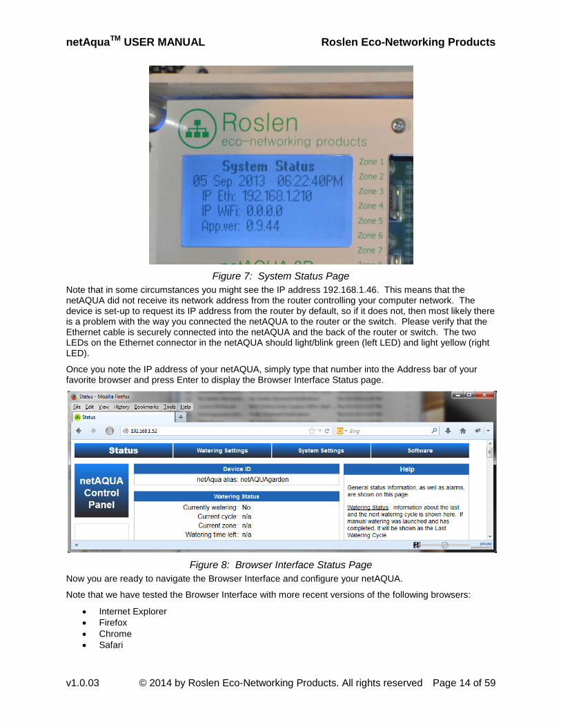
2.2.1. Device IP Address on the LCD Push either the Scroll Up or the Scroll Down button to change the LCD to the System Status page. The IP address of your netAQUA will be identified on the line starting with IP Eth, and will look something like the example shown in the image below.
netAquaTM USER MANUAL Roslen Eco-Networking Products
v1.0.03 © 2014 by Roslen Eco-Networking Products. All rights reserved Page 14 of 59
Figure 7: System Status Page
Note that in some circumstances you might see the IP address 192.168.1.46. This means that the netAQUA did not receive its network address from the router controlling your computer network. The device is set-up to request its IP address from the router by default, so if it does not, then most likely there is a problem with the way you connected the netAQUA to the router or the switch. Please verify that the Ethernet cable is securely connected into the netAQUA and the back of the router or switch. The two LEDs on the Ethernet connector in the netAQUA should light/blink green (left LED) and light yellow (right LED).
Once you note the IP address of your netAQUA, simply type that number into the Address bar of your favorite browser and press Enter to display the Browser Interface Status page.
Figure 8: Browser Interface Status Page
Now you are ready to navigate the Browser Interface and configure your netAQUA.
Note that we have tested the Browser Interface with more recent versions of the following browsers:
• Internet Explorer • Firefox • Chrome • Safari

netAquaTM USER MANUAL Roslen Eco-Networking Products
v1.0.03 © 2014 by Roslen Eco-Networking Products. All rights reserved Page 15 of 59
• Opera.
In some cases, you may need to select the Compatibility View option in Internet Explorer to properly show Browser Interface pages. You select this option by clicking on the little broken page marker to the left of the address bar in Internet Explorer.
2.2.2. Type the Name of Your netAQUA into the Browser Address Bar The netAQUA supports the NetBIOS protocol, which is build into most Microsoft Windows-based computers. To connect to the netAQUA simply type it’s name into the address bar of your favorite browser and press Enter. In the examples below, the device is called netAQUAgarden, but the default name in all new units shipped to customers is netAQUA. This is what you would type in the address bar; the name netAQUA is not case sensitive, so typing in NETaqua or netAQUA or netaqua will yield the same result.
Figure 9: Browser Interface Access Through NetBIOS
A few caveats related to NetBIOS. First, this is a Windows only feature, not available on MAC computers.
Next, you may have to precede the name of the device with the text http:// as in the following example using the Chrome browser.
Figure 10: Browser Interface Access Through NetBIOS with Chrome Browser
And finally, the NetBIOS functionality may be disabled on your Windows computer. If you type the name of the device as shown above and you do not see the Status page, NetBIOS may simply be turned off. In this case search the internet for information on how to enable this feature in Windows. Each version of Windows is a little different in this respect, and so this topic is outside the scope of the netAQUA manual.

netAquaTM USER MANUAL Roslen Eco-Networking Products
v1.0.03 © 2014 by Roslen Eco-Networking Products. All rights reserved Page 16 of 59
2.2.3. Use the netFINDER Application The Resource CD that came with your netAQUA contains a folder named netFINDER. This is a Windows application that locates all netAQUA devices on your computer network. This program can be a very convenient way to access one or more netAQUA controllers on your network. Simply copy the folder, or its contents, to any location on your hard disc. There is no installation required, but you must copy all three files contained in that folder to the same folder/directory on a computer that has access to your network.
Once the application and the two related files are copied, simply launch netFINDER by double clicking it. netFINDER will locate all netAQUAs on your network and will show them in a table. You can refresh the search results by selecting View/Refresh, or pressing the F5 key on your computer keyboard. When the netFINDER finds your device(s), all you need to do is double click the name of the device, which will open the Browser Interface in your default browser.
The netFINDER is a Windows application, which has been tested on Windows XP, Vista, 7, and 8.
2.2.4. Connect the netAQUA to your WiFi Network If you purchased the WiFi version of the netAQUA, you may want to connect it to your WiFi network. In order to do this, you first need to have an established connection over Ethernet to the netAQUA Browser Interface, which is covered in the earlier sections.
Once you have access to the Browser Interface, select the System Settings tab, which will open to the Network Settings section. The group of settings that define the netAQUA’s WiFi operation are labeled WiFi Port.
netAquaTM USER MANUAL Roslen Eco-Networking Products
v1.0.03 © 2014 by Roslen Eco-Networking Products. All rights reserved Page 17 of 59
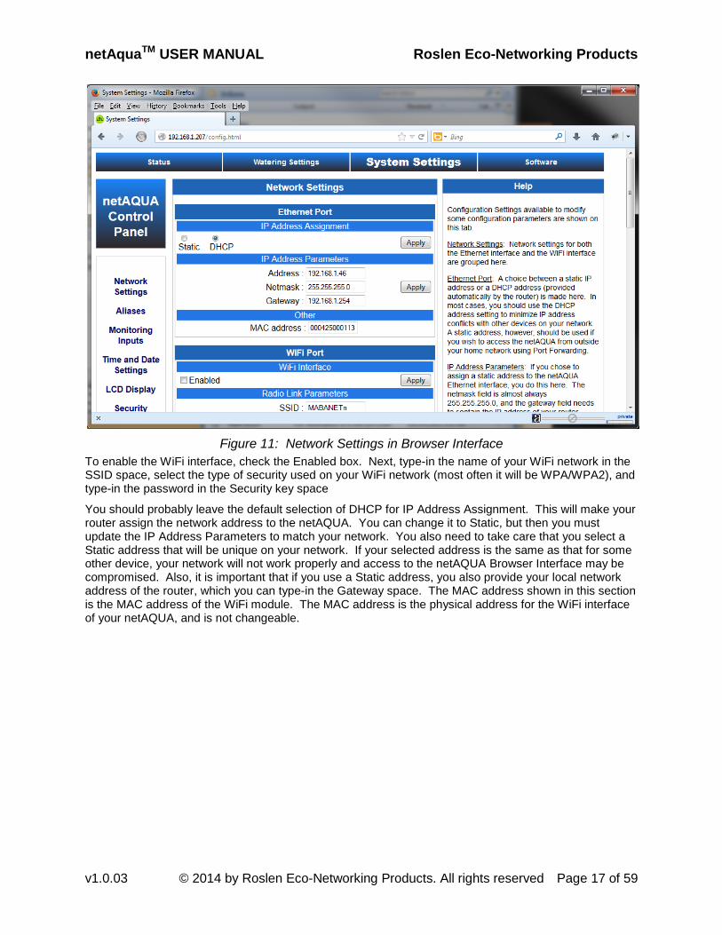
Figure 11: Network Settings in Browser Interface
To enable the WiFi interface, check the Enabled box. Next, type-in the name of your WiFi network in the SSID space, select the type of security used on your WiFi network (most often it will be WPA/WPA2), and type-in the password in the Security key space
You should probably leave the default selection of DHCP for IP Address Assignment. This will make your router assign the network address to the netAQUA. You can change it to Static, but then you must update the IP Address Parameters to match your network. You also need to take care that you select a Static address that will be unique on your network. If your selected address is the same as that for some other device, your network will not work properly and access to the netAQUA Browser Interface may be compromised. Also, it is important that if you use a Static address, you also provide your local network address of the router, which you can type-in the Gateway space. The MAC address shown in this section is the MAC address of the WiFi module. The MAC address is the physical address for the WiFi interface of your netAQUA, and is not changeable.

netAquaTM USER MANUAL Roslen Eco-Networking Products
v1.0.03 © 2014 by Roslen Eco-Networking Products. All rights reserved Page 18 of 59
Figure 12: WiFi Interface Settings
When all of these settings changes are made, you’ll be prompted to restart the device. You many do so by one of three methods:
• Go to the System Restart/Restore section of the System Settings tab, check the Confirmation box in the Restart System group of settings, and click Apply. After clicking OK on the pop-up window, the netAQUA will restart.
• Press the Enter button at the bottom of the device for more than 10 seconds, but less than 30 seconds. When you reach the 10 second mark, the Status LED will start to flash quickly, indicating that you can release the Enter button; the netAQUA will then restart.
• Simply power down the netAQUA and power it back up.
Note that it is not necessary to press Apply after each step. You can make all changes to your selected settings parameters and then press Apply. Pressing Apply multiple times does not have any adverse effects. Also, if you press Apply after each of the WiFi configuration settings changes, the netAQUA will prompt you to restart the device. You should click OK each time, but you do not have to restart the netAQUA until you’re done with all settings changes.
You should check if the netAQUA connects to your WiFi network before you install the device in its permanent location. During this test, disconnect the Ethernet cable from the netAQUA before restarting
2.2
, to make sure that the connection is via the WiFi interface. And place the device near the router to ensure a strong signal. Once the netAQUA restarts and completes the start-up process, you should see the WiFi LED flash red while the device attempts to connect to your WiFi network. After a time less than approximately 15 seconds, the netAQUA will connect and the LED will turn solid green. At this time, you have the three options described in Section to access the Browser Interface:
• Check the netAQUA IP address on the LCD; it will be different than that for the Ethernet interface. For reference, see Section 2.2.1 above.
• Type the name of the netAQUA in the address bar of your browser. However, in this case, you need to add the letter “w” at the end of the device name to distinguish access via WiFi from that through the Ethernet cable. For reference, see Section 2.2.2 above.
• Use the netFINDER application to locate the netAQUA on your network. You’ll see the device listed by name with the letter W added at the end to identify that it is connected via WiFi. For reference, see Section 2.2.3 above.
Operation of the Browser Interface over WiFi is identical to operation over the Ethernet cable interface.

netAquaTM USER MANUAL Roslen Eco-Networking Products
v1.0.03 © 2014 by Roslen Eco-Networking Products. All rights reserved Page 19 of 59
2.3. Connect the netAQUA to the Irrigation Valves Connecting the irrigation valves to your netAQUA is similar to the way these connections are made to traditional sprinkler controllers. First, you thread the control wire bundle through the bottom of the netAQUA, through the webbed grommet.
Figure 13: Webbed Grommet for Cable Entry
These cable bundles are typically five or seven wire, with each wire a different color. Once the cable bundle is brought inside the netAQUA, the insulation on each wire needs to be stripped about ½ inch (this can also be done before you insert the cable bundle into the netAQUA). At this point, you need to attach each zone wire to the appropriate zone terminal, as marked on the shield to the left of the green zone terminals. Finally, the common wire needs to be attached to one of the terminals labeled Common. That’s pretty much it.
Note that there are nine zone terminals available in the netAQUA. The ninth zone terminal is marked Master/Zone 9. As configured when the netAQUA is shipped from the factory that terminal is set-up as Zone 9, which operates the same as all of the other valve outputs. If you have a master valve, which opens-up watering to all of the other valves, or if you have a pump that needs to be turned on to provide the flow rate for the irrigation heads, you’ll need to connect these to the terminal marked Master/Zone 9. In addition, you will need to configure that terminal as the Master valve terminal. To do this, select the System Settings tab in the Browser Interface and then the Master Valve section. Next, check the Enabled box in the Master Valve setting group, and click the Apply button. You now have the Master/Zone 9 valve terminal set-up to power the master valve or a pump each time any of the other eight zones are powered.

netAquaTM USER MANUAL Roslen Eco-Networking Products
v1.0.03 © 2014 by Roslen Eco-Networking Products. All rights reserved Page 20 of 59
Figure 14: Irrigation Zones Wired at the netAQUA
Figure 15: Master Valve Enable
2.4. Program a Basic Watering Plan Now that your netAQUA is connected to your home computer network and to your irrigation valves, you can program the device to control your watering. You will find all of the main control settings for programming your watering plan on the Watering Settings tab. The Watering Global Options section will be the first one that you’ll see when you open the Watering Settings tab.

netAquaTM USER MANUAL Roslen Eco-Networking Products
v1.0.03 © 2014 by Roslen Eco-Networking Products. All rights reserved Page 21 of 59
Figure 16: Main Watering Plan Settings
To get started, globally enable watering by selecting the Enable radio button in the System Master Watering Control setting group, and clicking the Apply button. The remaining global watering options, such as Slope/Clay Settings, are described in other sections of this manual.
Next, proceed to program a Watering Cycle, by selecting one of the Watering Cycle sections. Our example shows Watering Cycle 1 morning. The names of the watering cycles, zones, and the device itself can be configured in the Aliases section of the System Settings tab.
Each cycle has to be independently enabled by selecting the Yes radio button and clicking Apply. The Timer Settings configuration group is where you select the frequency, start times, and zone watering durations for each connected zone. Once the selections are made using the drop-down menus, you’ll need to click the Apply button to make the changes permanent.
You can repeat this procedure for all other cycles that you plan to program for your watering plan.
Once the programming is complete, you can check when the next watering will begin on the Status tab.

netAquaTM USER MANUAL Roslen Eco-Networking Products
v1.0.03 © 2014 by Roslen Eco-Networking Products. All rights reserved Page 22 of 59
Figure 17: Cycle Programming
Figure 18: Status of Upcoming Watering

netAquaTM USER MANUAL Roslen Eco-Networking Products
v1.0.03 © 2014 by Roslen Eco-Networking Products. All rights reserved Page 23 of 59
2.5. Manually Launch Watering There may be occasions when you’ll wish to manually run a programmed cycle, or run a single zone for a defined period of time. This is done in the Manual Operations section of the Watering Settings tab
In the Start Trigger Settings group you can select the Cycle that you wish to run at any time. Just choose it from the drop-down menu and click Apply. The cycle will start immediately.
Similarly, you can select the Zone that you wish to run at any time, as well as the duration of watering. Clicking the Apply button will start watering the selected zone and duration.
Figure 19: Manual Watering Options
A few things to consider… First, manual controls will override any currently running automated cycles. So, if you choose to launch cycle 1 manually during the time that cycle 2 is scheduled to run, cycle 2 will stop execution and cycle 1 will begin immediately. Cycle 2 will not run until its scheduled time will come around again. The same holds true for manual starts of a zone. If any automated cycle is running and you launch a zone manually, that automated cycle will stop and the manually launched zone will run. The aborted cycle will run again at its normally programmed time.
You can also abort any manually started cycle or zone, or any automatic cycle during its execution time. Simply check the Yes box in the Abort Confirmation group and click Apply. Watering will stop immediately.
Note that you don’t have to manually abort a cycle or zone that has been started manually, if you wish to move on to another cycle or zone. Simply select the new cycle or zone to start manually and click the Apply button. Any previously manually started cycle or zone will stop and the newly started cycle or zone will begin watering.

netAquaTM USER MANUAL Roslen Eco-Networking Products
v1.0.03 © 2014 by Roslen Eco-Networking Products. All rights reserved Page 24 of 59
2.6. Access the netAQUA from Outside In order to access the netAQUA and control it from outside your home network, you will need to set-up Port Forwarding in your router. In most cases, you will also have to set-up a Dynamic Domain Name System (DDNS) account with one of many DDNS services available on the internet. First, let’s discuss Port Forwarding through your browser.
2.6.1. Setting up Port Forwarding Home and small business routers do not allow access to your home network from a device on the internet, unless a device within your home network requests the connection. This is so the computers on your home network and the data that they contain are not compromised. You can allow access from the internet through your home router and to the netAQUA by setting-up a Port Forwarding path. This will enable you to access the device from any Internet-connected device with a web browser, such as a computer at work, a tablet, or a smartphone. Port Forwarding has been around since the advent of home networks, and is a well established way to provide remote access to a device on your network. Each router manufacturer uses different terminology and provides differing settings to set-up a Port Forwarding path, so you need to request information about your specific router from its manufacturer. We will provide an example of Port Forwarding set-up in a Netgear WNR3500L router. All Netgear routers follow a similar pattern for setting-up Port Forwarding, and, again, other manufacturers’ routers approaches differ to one degree or another.
Port Forwarding settings on the Netgear WNR3500L are located in the Advanced section, under Port Forwarding/Port Triggering. To begin, you’ll need to click the Add Custom Service button, making sure that the Port Forwarding radio button is selected in the “Please select the service type.” Settings group. Once the Ports – Custom Services settings group opens up, you begin by typing in the Service Name. This can be anything you wish, so we can type netAQUA as the Service Name. The netAQUA only responds to TCP network data when access from the internet, you can leave the Service Type set to TCP/UDP, or change it to TCP. For the External Starting Port, you can select a number in the 50 thousands range, as these are allocated to custom, unregistered ports. Or, for something more manageable, you can select a port in the thousands, if it’s not already set-up for your network. It doesn’t really matter what port number you select, as long as:
• It is not used for some other device/service/function on your network, or • It is not port 80. Port 80 is used for HTTP traffic, which is the backbone of browser data. While
the netAQUA transfers HTTP data between it and the browser, we need to specifically allow external access only for the netAQUA Browser Interface, and nothing else. Selecting port 80 would direct all HTTP browser traffic to the netAQUA, making your browser sessions on other home computers not work at all.
The External Starting Port and the External Ending Port should be the same number, as you only need to set-up one port to access the netAQUA. So, the External port is what you’ll have to type-in to a browser on a device connected to the internet that you wish to use to access the netAQUA Browser Interface.
Once you choose the External port, you’ll need to choose the Internal Starting and Ending ports. Again, then can be the same port. With the Netgear WNR3500L router you have two choices:
• Check the “Use the same port range for Internal port,” in which case the external and internal port numbers will be the same, or
• Select a different Internal port (same number for Internal Starting Port and Internal Ending Port).
The Internal port identifies the port on a device connected to your home network, to which all data coming from the internet to the router addressed to the External port will be send to that device. You’ll notice on the netAQUA System Settings tab, Network Settings section, Network Services group that port 80 is shown there as default. This means that the netAQUA expects its HTTP traffic coming to port 80 (which is the standard port for HTTP traffic). So, for our example, let’s type-in 80 for the Internal Starting Port number. Since we only specified a single port through a unique definition of external ports, the Netgear router only allows us to set-up a single internal port.

netAquaTM USER MANUAL Roslen Eco-Networking Products
v1.0.03 © 2014 by Roslen Eco-Networking Products. All rights reserved Page 25 of 59
The last thing to do is to type-in the Internal IP Address information. This is the IP address of the netAQUA on your home network. It can be read from the LCD, on the Status tab of the Browser Interface, or using the netFINDER application. Unfortunately, unless you have a few devices connected to your home network and don’t turn them or the router off, the IP Address assigned by the router to the netAQUA is likely to change. So whatever you type-in for the Internal IP Address will most likely expire within a few hours or days and you will have to update the address. For this reason, it’s best to select a static address for your netAQUA, so that it is the same all the time. Details of how to set-up a static address for the netAQUA are provided in Section 2.6.3 below.
Figure 20: Netgear WNR3500L Port Forwarding Set-up Example
Once you click the Apply button, Port Forwarding for the netAQUA will be set-up in your router. That’s all that needs to happen with this function.
Now, you need to know the external address of your router. This can be checked in one of two ways:
• Your router will have a tab, or a page, or a section of it’s configuration interface called Router Status, or something similar. You can find the external address there, labeled as Internet Port IP Address, or something similar.
• You can open your browser and go to a website that will identify your external address. One such service is www.whatismyip.com, and there are others.
When you know the external address of your router, you have everything that you’ll need to access the netAQUA from the internet… with one caveat. That is, your Internet Service Provider (ISP) can change the external address assigned to your router at anytime, and will likely do that if you power down your router and power it back up again. This is why you need a DDNS service, which is described in Section 2.6.4 below. Or… you don’t have to worry about your ISP changing the external address of your router if you purchased the option to maintain a fixed external address. If you’re lucky enough to have a fixed address, then that’s all you need; no DDNS is required.
If you have a fixed external address for your router, or you just wish to try remote access before the ISP changes the external address, you can type the external address plus :external port that you configured for Port Forwarding in any internet-connected device outside of your home, and you’ll connect to the Browser Interface. An example of that address is, using our example above
107.144.172.56:4567
Or, for some browsers, you might need to type:
http://107.144.172.56:4567

netAquaTM USER MANUAL Roslen Eco-Networking Products
v1.0.03 © 2014 by Roslen Eco-Networking Products. All rights reserved Page 26 of 59
This will open the Browser Interface to the Status tab. Of course, in this case anybody who happens to come upon this address combination will access your netAQUA, so we strongly recommend that you set-up access control to your netAQUA Browser Interface, as described in the Section 2.6.2 below.
2.6.2. Setting-up Access Security on the netAQUA When enabled, access security will allow use of the Browser Interface only after you provide the User ID and Password combination. To enable it, go to the Security section of the System Settings tab. There, check the Enabled box and type-in your preferred credentials. Clicking Apply saves the settings.
Figure 21: Security Settings
You will have to enter your credentials whether you access the Browser Interface from within your home computer network, or from an internet connected device.
Figure 22: Security Credentials Entry
2.6.3. Setting-up a Static IP Address on the netAQUA In some cases, it may be best to operate the netAQUA with a fixed, static IP address. As mentioned in the Port Forwarding section (2.6.1) you pretty much have to use a static network address for Port Forwarding to work reliably. To set-up a static IP address for the netAQUA, select the System Settings tab. The Network Settings section opens up by default on this tab. In the Ethernet Port configuration group, select the Static radio button and type in the address that you wish to assign to the netAQUA in the Address field.
You can leave the Netmask field the way it is; it is almost always 255.255.255.0 for a typical home computer network.
You need to also provide the Gateway IP address for the netAQUA to work reliably with a static IP address. The Gateway IP address is the LAN IP Address of your router. LAN stands for Local Area Network, so this is the network address that your router has on your network.
Click the Apply button and the netAQUA will prompt you to restart the device to make the settings take effect.
Similar settings changes can be made for either the wired Ethernet port on your netAQUA or the WiFi port.

netAquaTM USER MANUAL Roslen Eco-Networking Products
v1.0.03 © 2014 by Roslen Eco-Networking Products. All rights reserved Page 27 of 59
Figure 23: Static IP Address Configuration
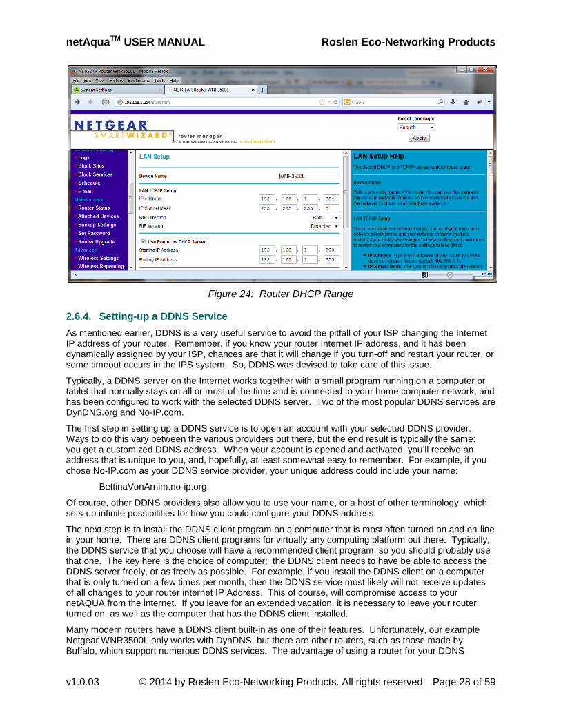
One thing that you have to ensure is that the static address that you select for the netAQUA must be unique on your network. There are as many ways to do that as there are router designs, so you might have to consult your router manufacturer for a detailed explanation. In our example case, the Netgear WNR3500L is set-up to assign network addresses in the range of 192.168.1.200 to 192.168.1.253. This can be seen in the “User Router as DHCP Server” group of settings in Figure 24: Router DHCP Range below. For clarity, DHCP stands for Dynamic Host Configuration Protocol, which is a fancy way of saying that the router is assigning network addresses to devices on the network.
netAquaTM USER MANUAL Roslen Eco-Networking Products
v1.0.03 © 2014 by Roslen Eco-Networking Products. All rights reserved Page 28 of 59
Figure 24: Router DHCP Range
2.6.4. Setting-up a DDNS Service As mentioned earlier, DDNS is a very useful service to avoid the pitfall of your ISP changing the Internet IP address of your router. Remember, if you know your router Internet IP address, and it has been dynamically assigned by your ISP, chances are that it will change if you turn-off and restart your router, or some timeout occurs in the IPS system. So, DDNS was devised to take care of this issue.
Typically, a DDNS server on the Internet works together with a small program running on a computer or tablet that normally stays on all or most of the time and is connected to your home computer network, and has been configured to work with the selected DDNS server. Two of the most popular DDNS services are DynDNS.org and No-IP.com.
The first step in setting up a DDNS service is to open an account with your selected DDNS provider. Ways to do this vary between the various providers out there, but the end result is typically the same: you get a customized DDNS address. When your account is opened and activated, you’ll receive an address that is unique to you, and, hopefully, at least somewhat easy to remember. For example, if you chose No-IP.com as your DDNS service provider, your unique address could include your name:
BettinaVonArnim.no-ip.org
Of course, other DDNS providers also allow you to use your name, or a host of other terminology, which sets-up infinite possibilities for how you could configure your DDNS address.
The next step is to install the DDNS client program on a computer that is most often turned on and on-line in your home. There are DDNS client programs for virtually any computing platform out there. Typically, the DDNS service that you choose will have a recommended client program, so you should probably use that one. The key here is the choice of computer; the DDNS client needs to have be able to access the DDNS server freely, or as freely as possible. For example, if you install the DDNS client on a computer that is only turned on a few times per month, then the DDNS service most likely will not receive updates of all changes to your router internet IP Address. This of course, will compromise access to your netAQUA from the internet. If you leave for an extended vacation, it is necessary to leave your router turned on, as well as the computer that has the DDNS client installed.
Many modern routers have a DDNS client built-in as one of their features. Unfortunately, our example Netgear WNR3500L only works with DynDNS, but there are other routers, such as those made by Buffalo, which support numerous DDNS services. The advantage of using a router for your DDNS

netAquaTM USER MANUAL Roslen Eco-Networking Products
v1.0.03 © 2014 by Roslen Eco-Networking Products. All rights reserved Page 29 of 59
updates is that you don’t have to install anything on any other computer. Also, the router in any home computer network tends to stay turned-on all the time, even if all other computers are turned off.
Once you set-up the account with a DDNS service provider and install the DDNS client on a computer or tablet connected to your network, you’re finally done. You will access your netAQUA from the internet using your unique DDNS address followed by :PortAddress that you set-up as part of Port Forwarding (Section 2.6.1). For our example, that would be:
BettinaVonArnim.no-ip.org:4567
So, what are the costs involved in setting-up and using a DDNS service? Fortunately, there are many options that are free, and those that carry a subscription fee are not costly. The key is that there are many adequate solutions that don’t cost anything, so you should first start there, with a provider that does not charge anything for a basic DDNS service. And, typically, the DDNS clients are free as well.
2.6.5. A Summary of Accessing Your netAQUA from the Internet Even though setting-up Port Forwarding might sound daunting at first, it ends-up being relatively straight forward if you follow these steps described in detail above:
1. Section 2.6.1, where we discuss setting up Port Forwarding through your router 2. Section 2.6.2, where we describe how to set-up Access Security on the netAQUA 3. Section 2.6.3, to see how to set-up a Static IP Address on the netAQUA 4. Section 2.6.4, to set-up a DDNS Service to maintain reliable access to the netAQUA from the
Internet.
Access to a device on your home network through Port Forwarding techniques has been an established method for many years, since home networking became widespread in the 1990’s. It works very reliably, and although the many router manufacturers propose different ways to set this up through their routers, in all cases the results are stable and secure.
2.7. Access the netAQUA Directly There may be cases when you need to access the netAQUA directly from your computer, without connecting it first to your home computer network. For example, if you change your router and set-up a new WiFi network, but it’s too far to run an Ethernet cable to the netAQUA, and you need to change the device WiFi settings to make it work on the new network.
To connect without a router, first turn off the netAQUA. Next, place your laptop near the netAQUA and insert one end of the Ethernet cable into your computer and the other end into the device Ethernet port. When your computer is fully powered-up, turn on the netAQUA and wait for it to completely start-up. Once it is ready, use the Scroll Up or Scroll Down buttons to navigate to the System Settings screen. Initially, the IP Eth field will show 0.0.0.0, but after about 30 seconds you should see the device set-up to operate on its fixed Ethernet address, whatever has been programmed into the Static IP field of the Network Setting section of the System Settings tab. In our example, the static address is 192.168.1.46. Once that static address is indicated on the LCD System Settings screen, the netAQUA is ready to connect directly to your computer.

netAquaTM USER MANUAL Roslen Eco-Networking Products
v1.0.03 © 2014 by Roslen Eco-Networking Products. All rights reserved Page 30 of 59
Figure 25: System Status LCD Screen with Default IP Address
At this point, you’ll need to configure your computer to connect to the netAQUA. Each operating system has a little bit different procedure to accomplish that, and we will show you the steps for a Windows 7 Home Premium PC. First, click the Start button and select the Control Panel to open up the selection of options to adjust your computer’s settings.
Figure 26: Control Panel
Click Network and Internet to open up this settings group.

netAquaTM USER MANUAL Roslen Eco-Networking Products
v1.0.03 © 2014 by Roslen Eco-Networking Products. All rights reserved Page 31 of 59
Figure 27: Network and Internet Settings Group
Click the Network and Sharing Center to open up this settings group.
Figure 28: Network Connections
Click Change adapter settings in the upper left corner.
Figure 29: Network Connections Listing

netAquaTM USER MANUAL Roslen Eco-Networking Products
v1.0.03 © 2014 by Roslen Eco-Networking Products. All rights reserved Page 32 of 59
Right click on the network interface that you would like to change and select properties on the pop-up menu. On the new menu that opens, select Internet Protocol Version 4 (TCP/IPv4) and click the Properties button.
Figure 30: Select Properties for IPv4
Select the “Use the following IP address” radio button to configure the computer’s IP address manually. Next, you’ll need to select and provide an IP address for your computer that is in the same subnet as the netAQUA. In our example, the netAQUA is 192.168.1.46, and the computer address can be anything from 192.168.1.0 to 192.168.1.255, except for 192.168.1.46. Let’s choose 192.168.1.1, with the mask left at the default value of 255.255.255.0.

netAquaTM USER MANUAL Roslen Eco-Networking Products
v1.0.03 © 2014 by Roslen Eco-Networking Products. All rights reserved Page 33 of 59
Figure 31: Manual IP Address Settings
Once these settings are made, you’re ready. Simply open a browser on your computer and in the address bar type in the netAQUA IP address, 192.168.1.46, and the Status page of the Browser Interface will open. From then on, you can make any changes that you need to any of the settings available on the Browser Interface.
When you’re done, you’ll need to return the computer to the settings needed for it to work on your network. Typically, all that you’ll need to do is to change the IP address configuration to select the “Obtain an IP address automatically” radio button. Then you can close all of the Control Panel related windows and that should be it. In some cases, you might wish to restart your computer for it to properly rest the network settings.
2.8. Update the Software in the netAQUA It is always best to keep the software in your netAQUA updated to the most recent version available. Please check the roslen.com website for any available software updates. The current software version running on your netAQUA is shown at the bottom of the Status tab, or on the Software tab. The current bootloader version is also shown on the Software tab. The bootloader is the base software that loads the main program on start-up.

netAquaTM USER MANUAL Roslen Eco-Networking Products
v1.0.03 © 2014 by Roslen Eco-Networking Products. All rights reserved Page 34 of 59
Figure 32: Software Tab
To start the update process, click the Browse button. This will open a dialog box where you’ll navigate to the folder where the update file is located, and select that file.
Figure 33: Update File Selection
Once the update file is selected, click the Upload button to begin the update process. The update process is divided into three steps:
• Upload, which is the process of transferring the update file from your computer to the netAQUA. • Validate, which is the process of checking the update file for errors. • Upgrade, which is the process of programming the new version of the software into the netAQUA
memory.
At each step, a status banner will be displayed above the Software Versions group on the Software tab, showing you the progress of the update. All three steps must complete for the update to be successful. At the end of a successful update, you will be prompted to restart the netAQUA, which you can do by one of these three methods:
• Navigate to the System Restart/Restore section of the System Settings tab, and check the Confirmation box in the Restart System group, followed by clicking Apply.

netAquaTM USER MANUAL Roslen Eco-Networking Products
v1.0.03 © 2014 by Roslen Eco-Networking Products. All rights reserved Page 35 of 59
• Press the Enter button at the bottom of the netAQUA for more than 10 seconds and less than 30 seconds. When the 10 second timeout is reached, the Status LED will start flashing to indicate that the system is ready to restart, which will happen once your release the button.
• Power cycle the netAQUA.
Once the system restarts it will be running the latest version of software.
Note that the bootloader will rarely be updated. The bootloader is the base software that loads the main program. If there is a bootloader software update, however, please take special care when performing that update to make sure that the update process is not interrupted by turning off the device. If this happens, you may render the device unusable, and it might have to be sent to us for repair. This is also important while updating the netAQUA software. While there are protections built into the system to prevent system failure during software update, these do not cover all possible scenarios, so please ensure that the device is powered-up during the update process for software as well as the bootloader.
2.9. Manually Start a Zone Using the LCD/Pushbutton Interface There is no doubt that the Browser Interface Control Panel is the easiest way to control the netAQUA but there are times when it is not practical or convenient to get on a networked device like a computer or smartphone. The LCD interface is made for those times when you or a caretaker are near the netAQUA and want to just turn a zone on and off or maybe run a full cycle. The interface may seem a bit confusing at the beginning, but once you see the logic, it will become straight forward. For the most part, the button rules are consistent throughout the interface.
The four pushbuttons are PROG, SCROLL DOWN, SCROLL UP, and ENTER. They allow you to go between pages and to program most of the watering related items in the Browser Interface. For each button you can either press it or hold it. Press means a momentary button push. Hold means pushing the button for 2 seconds or a bit more. The function of each is:
• Press SCROLL DOWN or SCROLL UP1. moves you between pages on same level, or
2. moves highlighting cursor between items on a programming page, or 3. changes the values of the highlighted items when selected to program.
• Hold SCROLL DOWN or SCROLL UP•
moves you vertically up and down between subpages Hold PROG
• puts page into programming mode.
Press PROG•
puts highlighted item into programming mode. Press ENTER
• is like “select” or “accept”.
Hold •
ENTER is like “apply change”. Hold SCROLL DOWN and SCROLL UP
will open Help pages if there is a flashing “?”.
To help you along the way, many pages have simple instructions on them, and there are contextual Help Pages as well. Anyway, to turn on a zone, this is what you do. If the LCD is off, touch any button to turn it on. You can enable continuous operation, but that is another story. You probably have noticed that after a couple of minutes of inaction on the buttons the page will revert to the Main Control Page. Starting on that page, press SCROLL UP. That will take you directly to the Manual Watering Operation page. Follow the direction on the page, that is, hold PROG to run. That will take you to the Manual Operation page. You will see a flashing “P” in the lower right which shows that you are in a programming mode, and a flashing “?” in the upper right which says that there is a Help page. You can get to the Help page by holding both SCROLL DOWN and SCROLL UP together. You also see a highlight square by “Cycle Number”. Since we want to turn on a zone you want to move the highlight to “Zone” so you press SCROLL DOWN once. Now you want to set the zone number that you want to turn on so you press PROG. The highlight starts to flash so it’s ready to be set. Press SCROLL UP or DOWN until you get the zone you want and press ENTER to accept. The duration is at one minute so if you want to change that press SCROLL DOWN to move the highlight to “Time” and repeat the sequence you used for the zone. Press PROG, Press SCROLL UP until you reach the number of minutes that you want, press ENTER. To activate the zone,

netAquaTM USER MANUAL Roslen Eco-Networking Products
v1.0.03 © 2014 by Roslen Eco-Networking Products. All rights reserved Page 36 of 59
hold ENTER to accept the page settings that you have set. That’s it. You can stay in manual mode to set other zones or exit by holding SCROLL UP. So, to repeat just the button pushes from the Manual Operations Settings page:
• Hold PROG to set page in program mode • Press SCROLL DOWN to highlight zone number • Press PROG to put zone number into program mode • Press SCROLL DOWN to change zone number • Press ENTER to accept zone number • Press SCROLL DOWN to highlight time • Press PROG to put time into program mode • Press SCROLL UP to change time • Press ENTER to accept time • Hold ENTER to apply page settings

netAquaTM USER MANUAL Roslen Eco-Networking Products
v1.0.03 © 2014 by Roslen Eco-Networking Products. All rights reserved Page 37 of 59
3. FUNCTIONS AND FEATURES The netAQUA is a full featured network-enabled irrigation controller. The various functions and features of the netAQUA are described in this section of the manual
3.1. Valve Solenoid Outputs Control The irrigation valve solenoid outputs are controlled in the same basic way as the standard consumer or commercial grade timer-based sprinkler controllers available from numerous manufacturers.
Current carrying requirements for the valve outputs for typical valve products are:
Table 1: Valve Output Current Carrying Requirements DEVICE INRUSH (A) HOLDING (A)
Hunter pump relay 2.33 .29
Rainbird ASVF valve .3 .19
Rainbird GB valve .41 .28
Rainbird HV-SS valve .25 .14
3.2. Timer Control A programmable timer control function is provided in all versions of the netAQUA, and includes four programmable timer watering control cycles. Details of the timer control programming and implementation are provided in a later section.
3.3. Manual Override of Timer Control Under most circumstances, the netAQUA operates under timer control. However, an option is provided to manually turn on either a specific valve, or one of the four cycles. Details of the manual override are provided in a later section.
3.4. Manual Watering Disable A manual watering disable function is provided using pushbutton switches available to the user. Details of the manual watering disable function are provided in a later section.
3.5. LEDs Two LEDs are provided, the Status LED and the WiFi LED. In units without WiFi, the WiFi LED is installed but not used.
3.5.1. Status LED A dual-color Status LED is provided to the outside of the netAQUA enclosure, at the bottom, to the left of the four control pushbuttons.
3.5.1.1. Status Indication
The Status LED is illuminated steady green when the netAQUA is plugged-in to AC power and is operating normally, and watering is globally enabled.
The Status LED blinks green-red when the netAQUA is operating normally, and watering is globally disabled.
The Status LED fast blinks green when the netAQUA is executing any watering process.

netAquaTM USER MANUAL Roslen Eco-Networking Products
v1.0.03 © 2014 by Roslen Eco-Networking Products. All rights reserved Page 38 of 59
The Status LED is illuminated steady red when an alarm condition is detected (further details are provided later in the document).
The Status LED blinks green when the processor is booting. The LED is controlled to blink green by the software, as early as possible during the boot sequence. The green blink rate during booting increases as the booting process proceeds towards completion until the Status LED is lit steady green, when the netAQUA transitions from the boot sequence to operation.
3.5.2. WiFi LED A dual-color WiFi LED is provided to the outside of the netAQUA enclosure, at the bottom, to the left of the four control pushbuttons.
The WiFi LED is Off when the WiFi interface is not enabled in the Browser Interface.
The WiFi LED blinks red when the WiFi interface is enabled, but there is no WiFi connection.
The WiFi LED is steady green when the WiFi interface is connected.
The WiFi LED is steady red when there is a WiFi failure.
On the non-WiFi versions of the netAQUA, the WiFi LED is not operational.
3.6. Monitoring The netAQUA includes functions to check local temperature, local rainfall, Internet temperature and humidity, and water flow.
3.6.1. Local Temperature A hardware interface is provided on the netAQUA to attach a temperature sensor. The user can enable extended watering times via the Browser Interface, when a temperature threshold is crossed.
Detection of temperature sensor failure or unintended removal is provided. When the temperature sensor is detected failed or removed, any extra watering settings are disabled and watering follows the timer control settings.
3.6.2. Local Rainfall A hardware interface is provided on the netAQUA to attach a standard, off-the-shelf rainfall sensor. The user can disable watering via the Browser Interface, when a rainfall threshold is crossed. The rainfall sensor supported by the netAQUA is of the Normally Open type, meaning that detected rainfall creates a contact closure that is then checked by the netAQUA.
3.6.3. Internet Temperature and Humidity A software interface is provided on the netAQUA to enable localized temperature and humidity verification from the Weather Underground Internet weather service. The user can extend watering times via the Browser Interface, when a temperature threshold is crossed, or shorten watering when a humidity threshold is crossed.
Location can be input via a city/state combination, zip code, latitude/longitude data, or weather station ID.
3.6.4. Water Flow A hardware interface is provided on the netAQUA to attach an accurate, high quality water flow sensor. The flow sensor averages the flow rate over a number of cycles, once a cycle has been programmed. If enabled an alarm will be issued, if the flow rate exceeds the average by an amount specified by the user. Conversely, an alarm will also be issued if the flow rate settles below the average by an amount specified

netAquaTM USER MANUAL Roslen Eco-Networking Products
v1.0.03 © 2014 by Roslen Eco-Networking Products. All rights reserved Page 39 of 59
by the user. Water flow rate processing applies only to programmed and enabled cycles. Once a cycle has been reprogrammed, water flow rate processing begins anew with the averaging of the flow rate.
3.6.5. Threshold Response Monitoring inputs threshold check is made immediately before the beginning of each programmed cycle.
When the temperature threshold is crossed, and extended watering is enabled, the netAQUA extends the cycle duration by the programmed amount.
When the humidity threshold is crossed, and shortened watering is enabled, the netAQUA shortens the cycle duration by the programmed amount.
When rainfall is detected and rainfall sensor processing is enabled, all automatic watering is cancelled for the duration of rainfall sensor active output. When rainfall is detected while a programmed cycle is running, the cycle is aborted.
3.6.6. Monitoring Input Threshold Crossing Notification Monitoring input threshold crossing indication is provided on the Status page of the Browser Interface, in the Notifications section, for all enabled and functioning (not in alarm) monitoring inputs. Information that is displayed depends on the Monitoring input threshold that has been crossed, and all crossed thresholds are displayed. The possible messages are:
- Local high temperature threshold crossed - Local low temperature threshold crossed - Internet high temperature threshold crossed - Internet low temperature threshold crossed - Internet high humidity threshold crossed - Rain detected.
In addition, a summary message is provided about the status of the upcoming next watering cycle, which can be modified as a result of a monitoring input threshold crossing. The possible status messages are:
- Scheduled to run as programmed - May be extended due to high temperature - May be shortened due to high humidity - May be cancelled due to low temperature - May be cancelled due to rain delay.
Only the overriding status message is shown. For example if both the Internet high humidity threshold is crossed and rain detected conditions exist, the only status message that is shown is “May be cancelled due to rain delay.”
3.7. Ethernet Interfaces There are two Ethernet interfaces provided in the netAQUA:
1. Ethernet interface A, a 10/100 BaseT via an RJ-45 connector
2. Ethernet interface B, an 802.11b/g/n WiFi via an on-board circuit.
On the non-WiFi version of the netAQUA, only Ethernet interface A is provided.
3.8. netAQUA Browser Interface The netAQUA Browser Interface is provided that can be viewed and driven via a standard web browser, such a Microsoft Internet Explorer or Firefox.

netAquaTM USER MANUAL Roslen Eco-Networking Products
v1.0.03 © 2014 by Roslen Eco-Networking Products. All rights reserved Page 40 of 59
3.8.1. Tabbed Navigation The Browser Interface has four pages. The top level, home page includes the status interface, the second page includes the watering settings interface, the third page includes the system settings interface, and the fourth page provides the software download interface. Each page includes a help column that contains a description of the status, functions, and settings that can be seen/controlled on that page. The pages are arranged in tabbed format.
The Browser Interface can be user ID/password protected, with a default user ID/password combination available before first use or after reset to factory defaults. The user ID/password protection is provided for all pages. The default user ID/password Admin/Password. The user ID/password protected access enable control is provided on the Configuration page. The user ID/password combination is case sensitive, so Admin is different from admin.
3.8.1.1. Status Page
Status information is provided on the home page of the Browser Interface. The Status information includes:
1. Watering Status:
o Currently watering: Yes, No
o Current cycle: n/a, cycle number
o Current zone: n/a, zone number
o Watering time left: n/a, time left to water for cycle and zone
o Last watering cycle: days, hours, minutes
o Next watering cycle: days, hours, minutes.
2. Monitoring:
o System temperature: degrees F or C
o Local temperature: not enabled, degrees F or C
o Local rainfall: not enabled, rain delay, no rain delay
o Internet weather: not enabled, enabled
o Water flow sensor: cumulative gallons used, instantaneous gallons per minute.
3. Notifications and Network Information:
o Temperature sensor failure
o LCD display failure
o Internet temperature and humidity not available, if enabled
o Monitoring threshold(s) crossing(s) for all enabled monitoring inputs.
4. Internet Weather Forecast:
o Weather forecast for the programmed location, if enabled, as read from the weather underground server.
5. Network Information:
o Ethernet interface IP address
o WiFi interface IP address
o WiFi security, signal strength or not connected
o WiFi access point name.

netAquaTM USER MANUAL Roslen Eco-Networking Products
v1.0.03 © 2014 by Roslen Eco-Networking Products. All rights reserved Page 41 of 59
6. Time and Date:
o Time: hour, minute, second, in AM/PM or 24 hour format
o Date: month, day, year
7. Uptime: days, hours, minutes, seconds since last device power-up
8. netAQUA model, serial number, software application version, software bootloader version information.
The Last Watering indication and the Next Watering indication are not shown while a cycle is active. These update when the current watering cycle ends.
3.8.1.2. Watering Settings Page
The Watering Settings page includes all watering control settings for the netAQUA.
3.8.1.2.1. Global Watering Settings
The global controls provided for watering control include:
1. System Master Watering Control: Enable, Disable
2. Slope:
a. Enable (check)
b. Watering breaks: number (1 to 5)
c. Break duration: minutes (1 to 120).
3. Local temperature:
a. Enable (check)
b. Threshold: degrees F (60 to 120 in one degree increments), or degrees C (15 to 50 in one degree increments)
c. Extra watering for each zone: percentage (5 to 70 in 5 percent increments).
4. Local rainfall:
a. Enable (check)
5. Internet temperature and humidity:
a. Enable internet temperature (check)
b. Temperature threshold: degrees F (60 to 120 in one degree increments), or degrees C (15 to 50 in one degree increments)
c. Extra watering for each zone: percentage (5 to 70 in 5 percent increments).
d. Enable internet humidity (check)
e. Humidity threshold: percentage (60 to 100 in one percentage increment)
f. Reduced watering for each zone: percentage (5 to 70 in 5 percent increments).
6. Freezing temperature protection:
a. Enable (check)
b. Threshold temperature below which watering is automatically disabled (degrees F from 14 to 50, or degrees C from -10 to 10).
The Slope, Local temperature, Local rainfall, and Internet temperature and humidity controls are only provided in the Browser Interface. The Enable watering cycle and Watering timer controls are

netAquaTM USER MANUAL Roslen Eco-Networking Products
v1.0.03 © 2014 by Roslen Eco-Networking Products. All rights reserved Page 42 of 59
synchronized between the Browser Interface settings and at device settings configured via the LCD/pushbutton switches.
The order of precedence for temperature, rainfall, and humidity controls is:
1. Local rain 2. Internet rain 3. Local temperature 4. Internet temperature 5. Internet humidity
Either local or internet thresholds can trigger watering modifications. For example, if the local rain sensor is not active but internet weather indicates rain, watering will not occur.
Humidity threshold, if enabled, decreases automated watering if no temperature thresholds are crossed. If either temperature threshold is crossed, the humidity threshold is disregarded.
3.8.1.2.2. Watering Cycles
The controls provided for each watering cycle include:
7. Enable watering cycle: Yes, No
8. Watering timer:
a. Frequency: Daily, Select Days, Even Days, Odd Days, Every Two Days, Every Three Days
b. Start time: hour, minute
c. Duration for each of the nine zones: minutes (OFF, 1 to 120 minutes)
3.8.1.2.3. Manual Operation
The controls provided for manual starts include:
1. Cycle number (1 through 4) 2. Zone number (1 through 9 (or 8 if Master Valve is enabled)) 3. Duration for specified zone: minutes (0 to 120).
When a manual start is initiated, it executes immediately. Only one manual start is possible concurrently. Manual start vs. timer control conflicts are discussed in Section 3.10.3.
3.8.1.2.3.1. Abort A control is provided to abort watering. When this is selected during an active watering cycle, the cycle aborts. When this is selected during an active manual start, the manual start aborts.
3.8.1.3. System Settings Page
The System Settings inputs are divided into sections, with each section including:
1. Network settings:
a. Ethernet port:
i. Static or DHCP IP address assignment
ii. IP address (used for Static address)
iii. Network mask of the connected network
iv. Gateway IP address (must be provided when Static address is used).
v. MAC address, provided for reference and not editable.
b. WiFi port:

netAquaTM USER MANUAL Roslen Eco-Networking Products
v1.0.03 © 2014 by Roslen Eco-Networking Products. All rights reserved Page 43 of 59
i. WiFi interface enabled (check)
ii. SSID
iii. Security
1. Type
2. Key
iv. Static or DHCP IP address assignment
v. IP address (used for Static address)
vi. Network mask of the connected network
vii. Gateway IP address (must be provided when Static address is used).
viii. MAC address, provided for reference and not editable.
c. HTTP port number (typically set to 80).
2. Aliases:
a. netAQUA alias
b. Cycle alias for each watering cycle
c. Zone alias for each zone valve.
3. Monitoring inputs:
a. Local temperature sensor installed (check)
b. Local rainfall sensor installed (check)
c. Internet temperature and humidity enabled (check)
d. Internet temperature and humidity location:
i. State, city
ii. Zip code
iii. Latitude, longitude
iv. Weather Underground Station ID
e. Degrees F or degrees C selection.
4. Time and Date settings:
a. Localization for time zone
b. Month, day, and year drop down menus
5. Clock settings:
a. AM/PM or 24 hour type clock selection
b. Hour and minute drop down menus
6. Enable Network Time Protocol to obtain date and time from an Internet server (check)
7. LCD display:
a. Continuous operation enable (check)
8. Security (Browser Interface access protection):
a. User ID (case sensitive)
b. Password (case sensitive)

netAquaTM USER MANUAL Roslen Eco-Networking Products
v1.0.03 © 2014 by Roslen Eco-Networking Products. All rights reserved Page 44 of 59
9. Selection to use a Master Valve, or to control a ninth watering Zone.
10. Selection to restart the netAQUA with default configuration settings.
11. Selection to restart the netAQUA.
3.8.1.4. Software Page
The creation date and version of the current software operating on the netAQUA is shown on the Software page, for both the Application and the Bootloader. The application is the main software and the bootloader is the base software that loads the application.
Software update is possible for both netAQUA software elements, the bootloader, and application.
Software update is done by the user selecting a single download image stored on the host PC. A host PC is defined as the computer which initiates the web browser session. An update status countdown is shown indicated the expected wait until completion of the update, in percentage complete.
There are three distinct stages to the software update process:
• Upload, which is the process of transferring the update file from your computer to the netAQUA. • Validate, which is the process of checking the update file for errors. • Upgrade, which is the process of programming the new version of the software into the netAQUA
memory.
All three stages must complete successfully for the update. Finally, once the update is complete, it is necessary to restart the netAQUA for the new software version to take effect.
3.8.2. Accessibility The Browser Interface is accessible from a standard web browser on the LAN (Local Area Network) and anywhere on the Internet; the tested browsers include:
• Microsoft Internet Explorer • Mozilla Firefox • Apple Safari • Opera • Google Chrome.
3.9. LCD/Pushbutton Interface The Deluxe versions of the netAQUA include an LCD display and 4 pushbuttons on the bottom of the enclosure. The display is used to show various configuration settings of the device, as well as to allow programming of the watering control timer system operation locally. The user interface consisting of LCD “pages” and the pushbutton controls allow the user to switch between the pages following a hierarchical structure.
3.9.1. Basic Pushbutton Operation The four pushbuttons are PROG, SCROLL DOWN, SCROLL UP, and ENTER. They allow you to go between pages and to program most of the watering related items in the Browser Interface. For each button you can either press it or hold it. Press means a momentary button push. Hold means pushing the button for 2 seconds or a bit more. The function of each is:
• Press SCROLL DOWN or SCROLL UP1. moves you between pages on same level, or
2. moves highlighting cursor between items on a programming page, or 3. changes the values of the highlighted items when selected to program.
• Hold SCROLL DOWN or SCROLL UP•
moves you vertically up and down between subpages Hold PROG
• puts page into programming mode.
Press PROG puts highlighted item into programming mode.

netAquaTM USER MANUAL Roslen Eco-Networking Products
v1.0.03 © 2014 by Roslen Eco-Networking Products. All rights reserved Page 45 of 59
• Press ENTER•
is like “select” or “accept”. Hold
• ENTER is like “apply change”.
Hold SCROLL DOWN and SCROLL UP
3.9.1.1. LCD Wakeup
will open Help pages if there is a flashing “?”.
The LCD can be set in the Browser Interface under System Settings>LCD Display for continuous operation or intermittent operation for power saving. If continuous operation of the LCD and backlight is disabled in the Browser Interface, the LCD is enabled for 2 minutes when any of the pushbuttons is momentarily pressed. If at any time prior to the end of the 2 minute period any of the buttons is pressed, the LCD and backlight continues to operate for 2 minutes. If the LCD is off and you press a button, the first press simply activates the LCD and the second press will cause the button to provide its programmed function.
3.9.2. Basic Programming Operation The start of programming is possible on any of the Watering Cycle or Manual Watering Operation pages. Programming mode is entered when the PROG pushbutton switch is pressed for at least two seconds (hold). At all times when the programming mode is in effect, the letter “P” flashes in the lower right corner of the screen.
When the programming mode is entered, the first programmable field is highlighted. When the SCROLL DOWN or SCROLL UP button is pressed, the highlight advances to the next programmable field. When the last (or first) programmable field is reached in the given direction (down or up) on the current screen, the first (or last) programmable field is highlighted.
When the PROG pushbutton is pressed while a programmable field is highlighted, that programmable field begins to flash. While the field is flashing, successive presses of the SCROLL DOWN or SCROLL UP buttons cycles through the possible values. When the ENTER pushbutton is held, the currently selected value becomes stored for that programmable field, and that programmable field stops flashing and becomes only highlighted.
3.9.2.1. Special Case – Global Watering Enable/Disable
A special case for user programming exists on the Main Control page. When the LCD interface is at this page, you can hold the ENTER pushbutton to toggle the Global Watering Enabled condition. This single button operation is intended to make it easy for a local user to quickly override automatic programming and shut off watering. The system can be re-enabled with this control as well.
3.9.3. Top Level LCD Pages There are 5 top level pages that can be seen by pressing the SCROLL DOWN/UP buttons on the bottom of the enclosure. The pages are, in the order of SCROLL DOWN presses:
• Main Control Page • Watering Status • System Status • Automatic Watering Settings • Manual Watering Operation.
Pressing SCROLL UP takes you in the opposite direction between the pages so that you can go directly from the Main Control Page to Manual Watering Operation.
3.9.3.1. Main Control Page
The first page is the Main Control page and shows the overall watering status of the netAQUA and allows a local user to quickly override automatic watering and shut the watering off or, of course, enable the system to run normally. The Main Control page contains the following information:
• Global Watering: Enabled or Disabled

netAquaTM USER MANUAL Roslen Eco-Networking Products
v1.0.03 © 2014 by Roslen Eco-Networking Products. All rights reserved Page 46 of 59
• Hold ENTER to change.
The general arrangement of the Main Control page data follows the concept shown in Figure 34.
Main Control Page
Hold ENTER to changeGlobal Watering: Enabled
Figure 34: Main Control Page
The Hold ENTER to change function is a special case of programming. When the user holds the ENTER pushbutton switch for two seconds, the Global Watering enable status toggles between Enabled and Disabled.
When there is no user pushbutton switch activity for 2 minutes after the user has navigated to a page different from the Main Control page, the LCD reverts to the Main Control page.
3.9.3.2. Watering Status Page
The Watering Status page contains the following information:
• Currently Watering status: Yes or No • Currently watering cycle and zone, plus active or break phase for slope control • Last Cycle: days, hours, minutes • Next Cycle: days, hours, minutes.
The time is displayed in either AM/PM or 24-hour designations, depending on the time format setting in the Browser Interface.
The general arrangement of the Watering Status page data follows the concept shown in Figure 35.
Watering Status
Last Cycle: 00d, 01h, 02mNext Cycle: 01d, 22h, 58m
Currently Watering: NO
Figure 35: Watering Status Page
3.9.3.3. System Status Page
The System Status page contains select system level configuration information:
• Date: Day, Month, Year Time: HH:MM • IP Address of the Ethernet interface • IP Address of the WiFi interface • Software version
The time is displayed in either AM/PM or 24-hour designations, depending on the time format setting in the Browser Interface.
The general arrangement of the System Status page data follows the concept shown in Figure 36.

netAquaTM USER MANUAL Roslen Eco-Networking Products
v1.0.03 © 2014 by Roslen Eco-Networking Products. All rights reserved Page 47 of 59
Software: v1.00
System Status
IP WiFi: 192.168.1.199
16 Jul 2012 04:32:42PMIP Eth: 0.0.0.0
Figure 36: System Status Page
3.9.3.4. Automatic Watering Settings Page
The Automatic Watering Settings page is the top level of the Automatic Watering Settings hierarchy in the LCD interface.
The Automatic Watering Settings page contains the following information:
• Hold SCROLL DOWN to view/edit.
When the SCROLL DOWN pushbutton switch is held for two seconds, the interface descends to the watering cycles level of hierarchy.
The general arrangement of the Automatic Watering Settings page data follows the concept shown in Figure 37.
Automatic Watering
Hold SCROLL DOWNto view/edit
SettingsAutomatic Watering
Hold SCROLL DOWNto view/edit
Settings
Figure 37: Automatic Watering Settings Page
3.9.3.5. Manual Watering Operation Page
The Manual Watering Operation page is the top level of the Manual Watering Operation hierarchy in the LCD interface.
The Manual Watering Settings page contains the following information:
• Hold PROGRAM to run.
When the PROG pushbutton switch is held for two seconds, the interface descends to the manual watering programming level of hierarchy.
The general arrangement of the Manual Watering Operation page data follows the concept shown in Figure 38.

netAquaTM USER MANUAL Roslen Eco-Networking Products
v1.0.03 © 2014 by Roslen Eco-Networking Products. All rights reserved Page 48 of 59
Manual WateringOperation
Hold PROGRAM to run
Figure 38: Manual Watering Operation Page
3.9.4. Watering Cycles LCD Pages As mentioned, the user can descend to Watering Cycles level from the top level Automatic Watering Settings page by holding SCROLL DOWN. The Watering Cycles level contains four LCD pages where the user can view the four watering cycle settings and can enter the programming mode to change these by holding the PROG pushbutton switch.
There are four Watering Cycle pages, one for each of the four available cycles. Each Watering Cycle page contains the following data:
• Cycle: Enabled or Disabled Start time: HH:MM ? • Frequency: Daily, or M Tu W Th F Sa Su, or Every Odd Day, or Every Even Day, or Every
Second Day, or Every Third Day • Zone 1 watering time: minutes or OFF • Zone 2 watering time: minutes or OFF • Zone 3 watering time: minutes or OFF • Zone 4 watering time: minutes or OFF • Zone 5 watering time: minutes or OFF • Zone 6 watering time: minutes or OFF • Zone 7 watering time: minutes or OFF • Zone 8 watering time: minutes or OFF • Zone 9 watering time: minutes or OFF (unless Zone 9 has been configured for Master Valve
control).
The time is displayed in either AM/PM or 24-hour designations, depending on the time format setting in the Browser Interface.
The ? character in the upper right corner of the display indicates that a help page is available for the Watering Cycle page. Hold the SCROLL UP and SCROLL DOWN buttons together for two seconds to descend to the help page.
The general arrangement of a Watering Cycle page data follows the concept shown in Figure 39.
Cycle 1: Enabled 12:00PM ?
Z4:OFF Z5:OFF Z6:OFFZ7:OFF Z8:OFF
Frequency: DailyZ1:OFF Z2:OFF Z3:OFF
Figure 39: Watering Cycle
The Watering Cycle pages for all four watering cycles follows the same format.
3.9.4.1. Watering Cycles Programming
When the PROG pushbutton switch is held for two seconds, the interface descends to the automatic watering programming level of hierarchy.

netAquaTM USER MANUAL Roslen Eco-Networking Products
v1.0.03 © 2014 by Roslen Eco-Networking Products. All rights reserved Page 49 of 59
When the programming level for a watering cycle is reached, the first programmable field is highlighted. Press the SCROLL UP or SCROLL DOWN buttons to select the field to edit. Press the PROG button to edit the selected variable.
The current selected programmable field is highlighted and blinking. Press the SCROLL UP or SCROLL DOWN buttons to change the selected programmable field. Press the ENTER button to accept the change.
At any point while in the programming mode, when a programming field is not flashing, hold the ENTER button for two seconds to accept the programmed values and exit the programming mode.
The possible values for each programmable field are specified later in Section Error! Reference source not found.. A special case exists when you wish to program the watering cycle frequency. One of the possible values is “Select Days” or after it is programmed it will show the days previously programmed like “MoWeFr”. When you choose this value, and it is highlighted and flashing, you press the PROG switch again and a page to select the days of the week is presented. When the program days of the week page is reached, the first programmable field is highlighted. Just like on other programming pages, press the SCROLL UP or SCROLL DOWN buttons to select the field to edit and press the PROG button to edit the selected variable. As before, the current selected programmable field is highlighted and blinking. Press the SCROLL UP or SCROLL DOWN buttons to change the selected programmable field. Press the ENTER button to stop editing the selected value, and hold the ENTER button for two seconds to accept the change. Hold the SCROLL UP button for at least two seconds, to return the LCD interface to the Watering Cycle page that is in the programming mode.
The general arrangement of a watering frequency program page data follows the concept shown in Figure 40.
Mon: enable Tue: enable
Sun: enableHold ENTER when done
Wed: enable Thu: enableFri: enable Sat: enable
Figure 40: Watering Cycle Days of the Week Programming
3.9.4.2. Watering Cycles Help in Status Mode
The ? character blinks in the upper right corner of each Watering Cycle page while these are in Status mode, that is programming mode has not been entered. When you hold both the SCROLL UP and SCROLL DOWN buttons together for two seconds, the help page shown in Figure 41 is displayed.
Cycles Help: p1 of 1
- Hold SCROLL UP to exit- Hold PROG to edit page
- Press SCROLL DOWNfor next page
Figure 41: Watering Cycle Status Mode Help Page
Holding SCROLL UP returns the interface to the Watering Cycle page in Status mode.
3.9.4.3. Watering Cycles Help in Programming Mode
The ? character blinks in the upper right corner of each Watering Cycle page while these are in Programming mode. When you hold both the SCROLL UP and SCROLL DOWN buttons together for two seconds, the help pages shown in Figure 42 are displayed.

netAquaTM USER MANUAL Roslen Eco-Networking Products
v1.0.03 © 2014 by Roslen Eco-Networking Products. All rights reserved Page 50 of 59
Program Help: p1 of 2
- Press PROG to edit item- SCROLL UP/DN to change
- SCROLL UP/DN tohighlight item to set
Program Help: p2 of 2
programming mode
- Press ENTER to accept- Hold ENTER to exit
SDSU
Figure 42: Watering Cycle Programming Mode Help Page
Successive presses of the SCROLL DOWN or SCROLL UP pushbutton switches cycle through these two help pages. Holding SCROLL UP returns the interface to the Watering Cycle page in Programming mode.
3.9.5. Manual Operation Control Level LCD Page The Manual Operation Control level contains one LCD page where you can manually launch a complete watering cycle or an individual zone. From the Manual Watering Operation page the user can enter the programming mode by holding the PROG pushbutton switch. (See Figure 43: Manual Watering Operation Page).
While in the manual watering programming mode, you can set a cycle or zone and the desired time.
The Manual Operation page contains the following data settings:
• Cycle: 1 through 4 • Zone: 1 through 9 (or 8 if Zone 9 is configured for Master Valve control) • Time: minutes • Abort: YES or NO
The ? character in the upper right corner of the display indicates that a help page is available for the Manual Operation page. Hold the SCROLL DOWN and SCROLL UP buttons together for two seconds to descend to the help page.
The general arrangement of a Manual Operation page data follows the concept shown in Figure 43.
Manual Operation
Zone: ---- Time: 00Abort: NO
Cycle: ----
?
Figure 43: Manual Operation Control Page
If a cycle is currently watering, it’s corresponding indication indicates the current zone and number of minutes left. If a different cycle is desired for manual launch, the current cycle is automatically aborted when the new one is programmed. Only one manual watering cycle can be ON at any one time.
If a zone is currently watering, it’s corresponding indication indicates number of minutes left. In this case, when only a zone is running that is not part of a cycle, it must have been launched manually. A selection

netAquaTM USER MANUAL Roslen Eco-Networking Products
v1.0.03 © 2014 by Roslen Eco-Networking Products. All rights reserved Page 51 of 59
of another manual start zone then is possible without first aborting the currently watering zone. However, only one manual watering zone can be ON at any one time, so the currently watering zone will automatically abort.
3.9.5.1. Manual Watering Programming
When the programming level for a manual watering control is reached, the first programmable field is highlighted. Press the SCROLL UP or SCROLL DOWN buttons to select the field to edit. Press the PROG button to edit the selected variable.
The current selected programmable field is highlighted and blinking. Press the SCROLL UP or SCROLL DOWN buttons to change the selected programmable field. Press the ENTER button to finish editing the selected value.
At any point while in the programming mode, when a programming field is not selected, hold the ENTER button for two seconds to accept the changed value and execute manual watering.
The possible values for each programmable field are specified later in Section Error! Reference source not found..
3.9.5.2. Manual Watering Help in Status Mode
The ? character blinks in the upper right corner of the Manual Watering Operation page while it is in Status mode, that is programming mode has not been entered. If you hold both the SCROLL DOWN and SCROLL UP buttons together for two seconds, the help page shown in Figure 44 is displayed.
Cycles Help: p1 of 1
- Hold SCROLL UP to exit- Hold PROG to edit page
- Press SCROLL DOWNfor next page
Figure 44: Manual Watering Operation Control Status Help Page
Holding SCROLL UP returns the interface to the Manual Watering Operation Control page in Status mode.
3.9.5.3. Manual Watering Help in Programming Mode
The ? character blinks in the upper right corner of the Manual Watering Operation Control page while it is in the Programming mode. If you hold both the SCROLL UP and SCROLL DOWN buttons together for two seconds, the help pages shown in Figure 45 are displayed.

netAquaTM USER MANUAL Roslen Eco-Networking Products
v1.0.03 © 2014 by Roslen Eco-Networking Products. All rights reserved Page 52 of 59
Program Help: p1 of 2
- Press PROG to edit item- SCROLL UP/DN to change
- SCROLL UP/DN tohighlight item to set
Program Help: p2 of 2
programming mode
- Press ENTER to accept- Hold ENTER to exit
pSDpSU
Figure 45: Manual Watering Operation Control Programming Mode Help Page
Successive presses of the SCROLL DOWN or SCROLL UP pushbutton switches cycle through these two help pages. Holding SCROLL UP returns the user to the Manual Watering Operation Control page in Programming mode.
3.9.6. User Programming Details The start of programming is possible on any of the Watering Cycle or Manual Watering Operation pages. Programming mode is entered when the PROG pushbutton switch is pressed for at least two seconds (hold). At all times when the programming mode is in effect, the letter “P” flashes in the lower right corner of the screen.
When the programming mode is entered, the first programmable field is highlighted. When the SCROLL DOWN or SCROLL UP button is pressed, the highlight advances to the next programmable field. When the last (or first) programmable field is reached in the given direction (down or up) on the current screen, the first (or last) programmable field is highlighted.
When the PROG pushbutton is pressed while a programmable field is highlighted, that programmable field begins to flash. While the field is flashing, successive presses of the SCROLL DOWN or SCROLL UP buttons cycles through the possible values. When the ENTER pushbutton is held, the currently selected value becomes stored for that programmable field, and that programmable field stops flashing and becomes only highlighted.
3.9.6.1. Special Case – Global Watering Enable/Disable
A special case for user programming exists on the Main Control page. When the LCD interface is at this page, you can hold the ENTER pushbutton to toggle the Global Watering Enabled condition. This single button operation is intended to make it easy for a local user to quickly override automatic programming and shut off watering. The system can be re-enabled with this control as well.
3.10. Programmable Field Details for Watering
3.10.1. Programmable Fields for Automatic Watering Cycles The programmable fields for each of the Watering Cycles are:
• Enable • Start time • Frequency • Zone 1 duration

netAquaTM USER MANUAL Roslen Eco-Networking Products
v1.0.03 © 2014 by Roslen Eco-Networking Products. All rights reserved Page 53 of 59
• Zone 2 duration • Zone 3 duration • Zone 4 duration • Zone 5 duration • Zone 6 duration • Zone 7 duration • Zone 8 duration • Zone 9 duration (unless Zone 9 has been configured for Master Valve control).
3.10.1.1. Watering Cycle Enable
Possible values for the Watering Cycle enable are:
a. Enabled: the cycle starts watering at the programmed Start Time. b. Disabled: the cycle will not water.
3.10.1.2. Watering Cycle Start Time
Possible values for the Watering Cycle Start Time are:
a. Hour: Possible values for the Hour field are 1 through 24, or 1 AM through 12 AM and 1 PM through 12 PM, depending on the time format setting in the Browser Interface.
b. Minute: Possible values for the Minute field are 0 through 59. c. Half of day: Possible values are AM or PM, if enabled in the Browser Interface. If Browser
Interface is set for 24 hour time, then neither AM nor PM is displayed.
3.10.1.3. Watering Frequency
Possible values for Watering Frequency are:
a. Daily: the Watering Cycle operates every day. b. Every Second Day: the Watering Cycle operates every second day. When this selection is
made, the Watering Cycle will first operate not later than 24 hours from the moment that the selection was made.
c. Every Third Day: the Watering Cycle operates every third day. When this selection is made, the Watering Cycle will first operate not later than 24 hours from the moment that the selection was made.
d. Odd Days: the Watering Cycle will operate on every odd day of the month. e. Even Days: the Watering Cycle will operate on every even day of the month. f. Press ENTER to Set Days of Week: this value is selected to choose individual days of operation.
3.10.1.3.1. Set Days of Week
For each day of the week, the possible values are:
a. Enabled: the Watering Cycle will operate on the selected day. b. Disabled: the Watering Cycle will not operate on the selected day.
3.10.1.4. Zone Duration
Possible values for Zone Duration are OFF, 1, through 120 minutes.
3.10.2. Programmable Fields for Manual Watering Operation Control The programmable fields for the Manual Watering Operation Control page are:
• Cycle: 1, 2, 3, or 4 • Zone: 1, 2, 3, 4, 5, 6, 7, 8, or 9 (unless Zone 9 is configured for Master Valve control) • Time: OFF or minutes, 1 through 120 • Abort: YES or NO.

netAquaTM USER MANUAL Roslen Eco-Networking Products
v1.0.03 © 2014 by Roslen Eco-Networking Products. All rights reserved Page 54 of 59
When the value ON is programmed for the Abort field, the previously entered Watering Cycle or Zone will stop watering.
The Time value will be accepted and changeable only if a Zone number is programmed.
3.10.3. Programming Conflicts If programmed watering cycles interfere in any way, the watering cycle with the lower number will have precedence. For example, if watering cycle 1 is scheduled to start before the completion of watering cycle 3, then watering cycle 3 will abort at the moment when watering cycle 1 starts. If watering cycle 4 is scheduled to start before the completion of watering cycle 2, then watering cycle 2 will complete, and watering cycle 4 will begin at the point in its sequence when watering cycle 2 ends.
Manual cycle starts have precedence over any programmed watering cycles. For example, if watering cycle 3 is currently executing and a manual start is programmed for watering cycle 1, then watering cycle 3 will be automatically aborted and the manually started cycle 1 will start. Likewise, manual zone starts have precedence over any programmed watering cycles. For example, if a manual start is programmed for a single zone, then any ongoing watering cycle will be aborted automatically.
3.11. Factory Default Configuration The default settings are:
• User ID: Admin
• Password: Password
• DHCP: enabled
• IP Address: 192.168.1.44 cable, 192.168.1.45 WiFi
• Net Mask: 255.255.255.0
• Gateway Address: 192.168.1.1
• WiFi interface (if provided): disabled
• WiFi interface settings: cleared
• Zone solenoid valve control outlets (relays): Off
• Global watering: disabled
• Watering timer control: disabled
• Watering timer programming: cleared
• Network Time Protocol: enabled
• LCD and backlight: disabled for continuous operation (120s timeout)
• Monitoring: disabled.
3.11.1. Reset to Factory Default A return to default configuration settings will occur when the ENTER button is held for more than 30 and less than 60 seconds. The reset with return to the default configuration will initiate after the ENTER button is released in the qualifying window.
An alternative method to restore the default configuration is provided in the Browser Interface, in the System Settings tab.

netAquaTM USER MANUAL Roslen Eco-Networking Products
v1.0.03 © 2014 by Roslen Eco-Networking Products. All rights reserved Page 55 of 59
3.12. System Restart A system restart will occur when the ENTER button is held for more than 10 seconds and less than 20 seconds.
An alternative method to perform a system restart is provided in the Browser Interface, under the System Settings tab.
3.13. Operation Recovery without Current Time Data A special condition arises when the netAQUA starts-up and determines that date and time information is not available. This can occur when there is no Internet access or when the NTP feature is not enabled, and when the netAQUA has been turned off for a long period of time, so that the Real Time Clock (RTC) device has stopped maintaining the date and time. Under these circumstances, the date and time is programmed to Sunday, 00:00:01 (12:00:01 AM). All programmed watering cycles will execute based on this start time.
3.14. Freezing Temperature Protection If the netAQUA determines that the local temperature sensor is installed and enabled by the user, and with the Freezing Temperature Protection is enabled, any programmed cycles will execute, but only if the local temperature sensor indicates a temperature above the configured threshold.
If local temperature is not enabled, or the local temperature sensor is not installed or fails, all programmed cycle(s) will execute regardless of temperature. In this case, you must ensure that watering does not take place in freezing conditions.
3.15. No Internet Access Some of the netAQUA features rely on internet access to function properly. This includes processing of internet temperature and humidity. If these stimuli for cycle duration calculations are enabled, there will be an attempt to obtain them prior to the start of any programmed cycle. When this data is not available after three attempts to retrieve it, the netAQUA will calculate cycle duration without considering these stimuli. An alarm is provided in the Browser Interface indicating that the most recent completed cycle did not include the internet temperature and humidity information, only if this feature is enabled. The start of the next programmed cycle will reset this alarm.
3.16. Browser Interface/LCD Differences Functionality provided through the LCD interface is a subset of that provided in the Browser Interface. Table 2 provides a summary of which features are included in the Browser Interface only, or in both interfaces.
Table 2: Browser Interface/LCD Differences Feature Browser Interface and
LCD Browser Interface Only
Watering status Yes
Alarm status Yes
Cycle programming Yes
Manual operation Yes
Configuration programming
Yes
Firmware update Yes
Failure condition Yes (LCD only)

netAquaTM USER MANUAL Roslen Eco-Networking Products
v1.0.03 © 2014 by Roslen Eco-Networking Products. All rights reserved Page 56 of 59
4. Physical Interfaces The following physical interfaces are provided on the netAQUA. All cables that connect to the netAQUA are routed through a cable grommet at the bottom of the enclosure.
4.1. AC Input The 24 VAC power input interface is via a standard, top entry terminal block.
4.2. Valve Solenoid Control Outlets A top entry terminal block outlet is provided for each of the nine valve solenoid controls. The ninth terminal block outlet is configurable for either Zone 9 control or for Master Valve control.
Thee terminal block outlets are provided for the common wiring back from the solenoids.
4.3. Ethernet One RJ-45 Ethernet port is provided. The RJ-45 port includes standard Ethernet traffic LEDs.
4.4. WiFi A standard 802.11b/g/n WiFi interface is provided on the WiFi version of the netAQUA.
4.5. Expansion Module A six pin RJ-11 port is provided to attach an Expansion Module.
4.6. Power LED A dual-color Power LED is provided that is seen on the outside of the enclosure, along the bottom side.
4.7. WiFi LED A dual-color WiFi LED is provided that is seen on the outside of the enclosure, along the bottom side.
4.8. Pushbutton Switches Four tactile pushbutton switches are provided, which are accessible from the outside of the enclosure. These are the PROG, SCROLL DOWN, SCROLL UP, and ENTER pushbuttons.
4.9. Local Rainfall Sensor A top entry terminal block is provided for a contact closure input from a standard, off-the-shelf, normally open rainfall sensor.
4.10. Local Temperature Sensor A top entry terminal block is provided for a temperature sensor connection.
4.11. Water Flow Sensor A top entry terminal block is provided for a water flow sensor pulse input.
4.12. EM Power Three top entry terminal blocks are provided for a power and ground leads to the Expansion Module.
netAquaTM USER MANUAL Roslen Eco-Networking Products
v1.0.03 © 2014 by Roslen Eco-Networking Products. All rights reserved Page 57 of 59
5. TROUBLESHOOTING GUIDE
5.1. WiFi connection problem If the Wifi does not connect or connects intermittently there probably is a signal strength problem. In general, if another WiFi appliance like a smartphone or laptop will connect, so will the netAQUA. If the signal strength is weak there are 3 options:
Wifi signal power is reduced by intervening objects and walls. Metal walls are obviously worse than wood construction and stucco exterior walls are built with a metal mesh that also impedes radio waves substantially. The options, like for any WiFi appliance are:
Improve the path between the WiFi router/access point and the netAQUA by moving them closer or with fewer impediments.
Increase the power with a more powerful or advance design router/access point.
Add a Wifi repeater or range extender to your network.
5.2. Technical Support For technical support, please contact us via e-mail at [email protected], or call us at 530-885-0262.

netAquaTM USER MANUAL Roslen Eco-Networking Products
v1.0.03 © 2014 by Roslen Eco-Networking Products. All rights reserved Page 58 of 59
6. SPECIFICATIONS
6.1. Specifications table Table 3: Specifications
Input power 24 VAC with earth ground, 1.67A
Number of irrigation zones 9 zones or 8 with master valve/pump zone, expandable in 9/18 zone increments
Sensor inputs Temperature
Rain
Flow
Network connections 10/100 Ethernet RJ45
WiFi 802.11 bgn (optional)
Operating environment 0⁰ to 122⁰ F, -18⁰ to 50⁰ C

netAquaTM USER MANUAL Roslen Eco-Networking Products
v1.0.03 © 2014 by Roslen Eco-Networking Products. All rights reserved Page 59 of 59
7. FCC Notice This controller generates radio frequency energy and may cause interference to radio and television reception. It has been type tested and found to comply with the limits for a Class B computing device in accordance with Part 15 of FCC Rules. These limits are designed to provide reasonable protection against such interference in a residential installation. However, there is no guarantee that interference will not occur in a particular installation. If this equipment does cause interference to radio or television reception, which can be determined by turning the equipment off and on, the user is encouraged to try to correct the interference by one or more of the following measures:
• Reorient or relocate the receiving antenna
• Move the controller away from the receiver
• Plug the controller into a different outlet so that controller and receiver are on different branch circuits
If necessary, the user should consult the dealer or an experienced radio/television technician for additional suggestions. The user may find the following booklet prepared by the Federal Communications Commission helpful: “How to Identify and Resolve Radio-TV Interference Problems.” This booklet is available from the U.S. Government Printing Office, Washington, D.C., Stock No. 004-000-00345-4