netafim™ metal valve series - drip irrigation system netafim metal valves.pdf · low flows with...
TRANSCRIPT
NETAFIM™ METALVALVE SERIES

3
CONTENT
Features & Benefits 4
Technical Information 5
Pressure Reducing Valve 7
Pressure Sustaining/Relief Valve 8
Pressure Reducing/Sustaining Valve 9
Quick Pressure Relief Valve 10
Hydraulic/Electric Control Valve 11
Hydraulic Remote Control Valve 12
Standard Valves 13
Specialty Valves 14

4
FEATURES & BENEFITS
Reliable trouble free valve operation; controlled, smooth and accurate closing and opening at low flows with drip-tight sealing.
Extremely stable and accurate control during shut-off and regulation; provides versatile rangeability and low flow control.
High flow capacity and very low head loss resulting from the innovatively designed body and flow path.
Positive drip-tight sealing is guaranteed by the oval diaphragm’s design and its resilient sealing surface.
Easy inline maintenance is provided by top entry design.
Rugged, high quality construction meets applicable engineering standards.
Proven pressure, flow and level regulation pilots, electric solenoids and control accessories.
Design based on simplicity. Engineered to perform under the most demanding conditions.
Each valve assures a controlled close, which minimizes water hammer and absorbs the pressure shock caused by system shut-off.
The flow path is wide and clear of obstructions for superior hydraulic performance and lower pressure loss.
Netafim valves are capable of reducing pressures at extremely low flow rates, as well as high flow rates, due to the multi-functional oval diaphragm. The same diaphragm can open, close and reduce pressures down to 0.4 Bar.
The interior and exterior of the valve are treated with a pliable electrostatic spray polyester
coating that will not chip, is rust resistant, and stands up to sun, salt and other corrosive elements. The coating process includes pre-treatment blasting, electrostatic spraying of polyester, and oven-heated curing to bond the coating.
Netafim valves require minimal maintenance. The valve never needs to be removed from the line. The bonnet is easily removed revealing the diaphragm and spring that may require upkeep.
Netafim offers a complete line of multi-purpose pilots and accessories. By combining Netafim valves with precise hydraulic accessories, solutions to both common and more complex valve requirements are readily attained. The plastic pilot in particular, has new innovative features not available in similar type products; such as larger passages for quick reaction time and non-breakable directional assembly.
All Netafim valves can be controlled by 3-way pilots or 2-way control loops.
Standard valves can be controlled manually or by Electric, Pressure Reducing, PressureSustaining/Relief, Hydraulic Relay, and Quick Reacting Pressure Relief.
Additional valve control features include Surge Anticipating-Quick Relief, Pump Control, FlowRate Control, Two Stage Opening, Float Control, and Check Valve options.
CONSISTENT PERFORMANCE
DEPENDABLE CONTROL
EASY MAINTENANCE
PRESSURE REDUCTION OVER A WIDE FLOW RANGE
PROTECTIVE CLOTHING
HIGH EFFICIENCY - LOW HEAD LOSS
HYDRAULIC ACCESSORIES
■
■
■
■
■■■
5
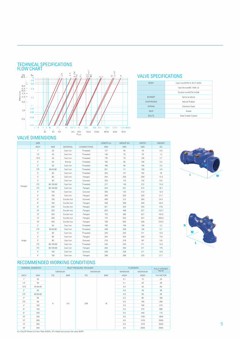
TECHNICAL SPECIFICATIONSFLOW CHART
VALVE SPECIFICATIONSBODY Cast Iron/ASTM A 45 CI S25A
Cast Bronze/BS 1400 LG
Ductile Iron/ASTM A-536
BONNET Same as above
DIAPHRAGM Natural Rubber
SPRING Stainless Steel
SEAT Acetal
BOLTS Steel Cobalt Coated
SIZE LENGTH (L) HEIGHT (H) WIDTH WEIGHT
INCH MM MATERIAL CONNECTIONS MM MM MM KG
Straight
1" 25 Cast Iron Threaded 127 55 78 0.9
1.5" 40 Cast Iron Threaded 140 70 78 1.2
1.5"S 40 Cast Iron Threaded 176 79 126 2.7
2" 50 Bronze Threaded 180 85 126 3.0
2" 50 Cast iron Threaded 186 84 126 3.0
3"R 80-50-80 Cast Iron Threaded 251 111 126 4.9
3" 80 Cast Iron Threaded 254 127 162 7.6
3" 80 Cast Iron Flanged 254 200 200 13.3
3" 80 Cast Iron Grooved 254 115 132 5.9
3"S 80-100-80 Cast Iron Threaded 317 146 212 12.9
3"S 80-100-80 Cast Iron Flanged 254 201 212 16.7
4" 100 Cast Iron Grooved 305 143 212 12.0
4" 100 Cast Iron Flanged 305 220 220 21.7
6" 150 Ductile Iron Grooved 436 212 300 24.2
6" 150 Ductile Iron Flanged 406 289 300 40.0
8" 200 Ductile Iron Flanged 521 345 345 47.5
10" 250 Ductile Iron Flanged 633 406 527 133.7
12" 300 Ductile Iron Flanged 753 480 527 161.8
14" 350 Ductile Iron Flanged 774 533 527 200.0
16" 400 Ductile Iron Flanged 756 620 526 318.2
Angle
2" 50 Cast Iron Threaded 156 156 126 3.2
3"R 80-50-80 Cast Iron Threaded 208 208 126 5.7
3" 80 Cast Iron Threaded 245 245 211 13.5
3" 80 Cast Iron Flanged 254 254 200 17.5
3" 80 Cast Iron Grooved 219 218 161 5.8
3"S 80-100-80 Cast Iron Threaded 245 245 211 13.5
3"S 80-100-80 Cast Iron Flanged 264 264 211 17.5
4" 100 Cast Iron Grooved 238 238 211 12.6
4" 100 Cast Iron Flanged 286 286 220 21.7
VALVE DIMENSIONS
NOMINAL DIAMETER INLET PRESSURE, PSI & BAR FLOWRATE FULLY OPENED VALVEMINIMUM MAXIMUM MINIMUM MAXIMUM
INCH MM PSI BAR PSI BAR M3/H M3/H *KV FACTOR
1" 25
6 0.4 228 16
0.1 15 24
1.5" 40 0.1 25 28
1.5"S 40-50-40 0.5 35 60
2" 50 0.5 40 95
3"R 80-50-80 0.5 55 95
3" 80 0.5 80 160
3"S 80 0.5 105 260
4" 100 0.5 165 270
6" 150 0.5 370 680
8" 200 0.5 440 710
10" 250 0.5 1100 1800
12" 300 0.5 1470 2000
14" 350 0.5 1470 2000
16" 400 0.5 2500 3500
RECOMMENDED WORKING CONDITIONS
Kv=Q/√ΔP Where Q=Flow Rate (M3/h), ΔP=Head loss across the valve (BAR)

6
P-21 2-way Pressure Reducing metal pilot. 7-230 psi (0.5 - 16 Bar)
P-22 2-way Pressure Sustaining metal pilot. 7-230 psi (0.5 - 16 Bar)
P-23 2-way Quick Relief metal pilot. 7-230 psi (0.5 - 16 Bar)
P-24 Altitude metal pilot. 7-230 psi (0.5 - 16 Bar)
P-31 3-way Pressure Reducing/Sustaining plastic pilot. 7-145 psi (0.5 - 10 Bar)
P-32 3-way differential pressure plastic pilot. 7-145 psi (0.5 - 10 Bar)
P-33 3-way Pressure Reducing/Sustaining Metal pilot. 7-230 psi (0.5 - 16 Bar)
P-36 3-way differential pressure metal pilot. 7-145 psi (0.5 - 10 Bar)
PILOT SPECIFICATIONS
PRINCIPAL OPERATION 3-WAY PRESSURE REDUCING
PRINCIPAL OPERATION 2-WAY PRESSURE REDUCING
PORT PRESSURE REDUCING
PRESSURE SUSTAINING
1 Sensing / Downstream
Sensing / Upstream
2 Vent Pressure / Upstream
3 Control Chamber
Control Chamber
4 Pressure / Upstream Vent
PORT PRESSURE REDUCING
1 Sensing / Downstream
2 Pressure / Upstream
3 Control Chamber

7
PRESSURE REDUCING VALVE
Netafim reducing configurations for general water supply systems with medium pressure rating. The plastic pilot model is best for irrigation and low-pressure applications. The plastic materials and straightforward design provide high corrosion resistance and cost-effective prices. The 2-way pilot configuration, together with the unique diaphragm, enables smooth and precise pressure control. Use Netafim valve for domestic, water works, and filtration networks.
Netafim valves are piloted hydraulic valves activated by line pressure. The pilot valve has a spring-loaded diaphragm that is sensitive to downstream pressure. The pilot’s spring is preset to the desired reduced pressure. The pilot valve maintains a constant downstream pressure by gradually opening and closing the Netafim valves at any flow rate.
3-way Pressure Reducing Valve for sizes 2”- 8” with pressure ratings up to 145 psi (10 Bar).
2 and 3-way Pressure Reducing Valve with pressure rating up to 232 psi (16 Bar).
Manual: Use the three-way selector to close or open the valve by turning the handle to C (closed) or O (open) positions. Automatic: Position the three-way selector handle to A (automatic). When the downstream pressure is lower than that of the pilot spring, the valve’s control chamber drains via ports 3 and 2 of the pilot to open the valve. When the downstream pressure is too high, the pilot diaphragm moves upward allowing ports 3 and 4 to connect, thus permitting line pressure to close the valve.
In three-way configurations, the control chamber drains out to atmosphere, permitting the valve to open entirely.
Adjust the reduced pressure set point with the adjusting screw on the pilot.
The Netafim Pressure Reducing Valve is activated by line pressure and controlled by the pilot valve. The pilot includes a spring-loaded diaphragm that is exposed to the downstream pressure. The displacement of the membrane due to downstream fluctuation defines the flow direction inside the pilot. When the downstream pressure is lower than desired, the valve is automatically directed to open. In the reverse case, it is automatically directed to close. When line pressure is inserted into the control chamber of the valve (above its diaphragm) the valve closes. When the control chamber drains, the valve opens as a result of the line pressure from below its diaphragm. In two-way configurations, the control chamber drains downstream, enabling faster reaction time and gradual opening without water discharge.
Manual: To open the Netafim valve, open isolation valves 1 and 2. To close the Netafim valve, close the downstream isolation valve. Automatic: When the downstream pressure is lower than that of the pilot spring, the control chamber drains downstream and the valve opens. In this case, there is a connection between port 3 (inlet upstream), port 1 or 2 (outlet downstream) and the control chamber. When the downstream pressure rises above the preset spring load, the pilot’s diaphragm is forced upward, closing port 1 or 2. The valve then begins closing and downstream pressure decreases.
APPLICATIONS
DESCRIPTION
AVAILABLE MODELS
CONTROL MODE - 3-WAY PLASTIC / METAL PILOT
ADJUSTMENT
FUNCTION
CONTROL MODE - 2-WAY PILOT
■
■

8
PRESSURE SUSTAINING / RELIEFVALVE
Use the pressure sustaining/relief valve to maintain constant upstream pressure and to avoid undesirable high-pressure situations. This protection is required for most irrigation systems, domestic and industrial utilities, and for general water supply systems. The 3-way plastic pilot model provides high resistance to corrosion at a cost effective price. It is best for irrigation, filtration manifolds, water treatment circulation and low-pressure domestic applications. The 2-way pilot command provides smooth and precise pressure control.
The pilot valve has a spring-loaded diaphragm that is exposed to upstream pressure. The valve is normally closed. With Pressure Relief Valves, only when the line pressure rises above a preset point does the valve open to reduce the excessive upstream pressure. The excess pressure is released off-line. Pressure Sustaining Valves reduce the excessive downstream pressure without causing surge hazards. When the line pressure drops beneath the desired point, the valve closes.
3-way plastic piloted pressure sustaining/relief valve for sizes 2”- 8” with pressure rating up to 145 psi (10 Bar)
2 and 3-way Pressure Sustaining/Relief Valve with pressure rating up to 232 psi (16 Bar).
Manual: To open the valve, open isolation valves 1 and 2. To close the valve, close the downstream isolation valve. The upstream isolation valve should remain open. Automatic: When the upstream pressure is lower than that of the sustained pressure set point, the valve’s control chamber is connected to the line. This connection occurs through ports 1 or 2 (inlet upstream) and port 3. The valve closes until the desired upstream pressure is achieved. When the upstream pressure rises above the set point, the pilot’s diaphragm is forced upward. Port 5 (outlet downstream) opens and the control chamber of the Netafim valve drains downstream, alleviating the excess pressure.
Adjust the sustained pressure with the adjustment screw on the pilot.
The Pressure Sustaining/ Relief Valve is activated by the line pressure and controlled by a pilot valve. A sustained pressure is preset by adjusting the pilot retaining spring. The pilot is connected to line pressure (upstream). The displacement of the pilot’s spring-loaded diaphragm due to upstream pressure defines the flow direction inside the pilot. When the upstream pressure is higher than the set point, the valve is piloted to open. Otherwise the valve remains closed, maintaining the upstream pressure. The excess line pressure is relieved downstream. In 3-way pilot configurations, the valve control chamber drains out, enabling the valve to open fully. In 2-way pilot configurations, the control chamber drains downstream, enabling faster reaction time and gradual closure without water discharge.
Manual: Use the three-way selector to close or open the valve by turning the handle to C (closed) or O (open) positions. Automatic: Position the three-way selector handle to A (automatic). When the upstream pressure is low, the pilot’s diaphragm is in its lowest position. The valve’s control chamber is exposed to line pressure through ports 2-3 of the pilot. The valve closes to sustain the upstream pressure. When the upstream pressure is higher than preset, the pressure overcomes the pilot’s spring and forces the pilot’s diaphragm to move upward. The connection between ports 3-4 opens and port 2 closes. The control chamber drains and the valve opens to relieve the excessive pressure downstream. In 3-way configurations, the control chamber drains out to atmosphere, permitting the valve to fully open.
APPLICATIONS
DESCRIPTION
AVAILABLE MODELS
CONTROL MODE - 2-WAY PILOT
ADJUSTMENT
FUNCTION
CONTROL MODE - 3-WAY PLASTIC / METAL PILOT
■
■

9
ADJUSTMENT
FUNCTION
CONTROL MODE - 3-WAY PLASTIC / METAL PILOT
PRESSURE REDUCING/ SUSTAININGVALVE
Use the pressure reducing/sustaining valve to define two pressure zones along a supply line. Typically, this occurs along a downhill flow.
Pressure Reducing/Sustaining valves are piloted hydraulic valves activated by line pressure and controlled by pilots. Both pilots have spring-loaded diaphragms. One pilot is responsive to upstream pressure and the other to downstream pressure. The combined operation of the two pilot valves sustains the preset minimum upstream pressure of the valve, and at the same time, reduces the downstream pressure to a preset maximum pressure. The valve opens or closes gradually to maintain both required pressures simultaneously.
3-way plastic piloted Pressure Reducing/Sustaining valve. Plastic pilot is used for 2" - 8" sizes with pressure rating up to 145 psi (10 Bar).
2 and 3-way pressure Reducing/Sustaining valve with pressure rating up to 232 psi (16 Bar).
Manual: Use the three-way selector to close or open the valve by turning the handle to C (closed) or O (open) positions. Automatic: Position the three-way selector handle to A (automatic). When the upstream pressure is low, the line pressure flows through ports 2-3 of the sustaining pilot and flows into the valve’s control chamber. The valve closes to sustain upstream pressure. When the upstream pressure reaches the set point, the diaphragm of the reducing pilot moves upward and connects ports 2-3. The control chamber drains through the sustaining pilot and exits port 2 of the reducing pilot. The valve then opens to the preset downstream pressure. When the downstream pressure is greater then the desired level, the reducing pilot’s diaphragm moves up, allowing water to flow into the control chamber through ports 4-3 of the sustaining pilot.
Adjust the pressure set points with the adjusting screws on the pilots.
The Pressure Reducing/Sustaining valve is activated by the line pressure and controlled by two pilot valves. Both pilots include spring-loaded diaphragms. The sustaining pilot is preset to sustain the upstream pressure at a preset point. The reducing pilot reduces the downstream pressure and maintains it at a lower preset level. Under normal flow conditions, the valve is partly open to sustain the upstream pressure and reduce the downstream pressure. It partly closes when the downstream pressure rises above the lower set point or when the line pressure drops below the upper set point. It opens again when the upstream pressure rises. In 3-way pilot configurations, the control chamber of the valve drains out to atmosphere, enabling the valve to fully open. In 2-way pilot configurations the control chamber drains downstream, enabling faster reaction time and gradual opening without water discharge.
Manual: To open the valve, open isolation valves 1 and 2. To close the valve close the downstream isolation valve. The upstream isolation valve should remain open. Automatic: When the upstream pressure is low, the control chamber is connected through the 2-way sustaining pilot to the line pressure and the valve closes. When the line pressure rises and overcomes the spring of the sustaining pilot, the pilot’s diaphragm moves upward to open port 5 (outlet downstream). The control chamber then drains downstream through the 2-way reducing pilot. The valve then opens and reduces the upstream pressure. As the line pressure is reduced, the sustaining pilot closes, as does the valve. If the downstream pressure is greater than the set point of the reducing pilot, the reducing pilot’s diaphragm moves upward and closes port 1 or 2 (outlet downstream). The control chamber is connected to the upstream pressure and the valve closes.
APPLICATIONS
DESCRIPTION
AVAILABLE MODELS
CONTROL MODE - 3-WAY PLASTIC / METAL PILOT
ADJUSTMENT
FUNCTION
CONTROL MODE - 2-WAY PILOT
■
■

10
QUICK PRESSURERELIEF VALVE
A Quick Pressure Relief Valve (QPR) protects water systems from rapidly increasing excess pressure. It is recommended to install the Netafim QPR valve at the start of the system near the main supply line or booster pump.
The Pressure Relief Valve is a piloted hydraulic valve activated by line pressure. The 2-way pilot has a spring-loaded diaphragm that is sensitive to upstream pressure. The valve is normally closed. As the line pressure rises above the preset level, the valve opens quickly to relieve the excess pressure.
The valve is a general application 2-way piloted Pressure Relief Valve with a pressure rating up to 232 psi (16 Bar).
The Pressure Relief Valve is activated by line pressure. The displacement of the diaphragm in the pilot is due to a rise in line pressure against the spring force. As the pressure increases above the set point, the water flow inside the pilot is directed so that the valve quickly opens.
Automatic: When the line pressure is low, the quick relief pilot and the valve are closed by line pressure. The valve remains closed until the line pressure is higher than the set point of the pilot. As pressure increases above the set point, the diaphragm moves upward under the line pressure and port 5 (outlet downstream) of the pilot opens, allowing the control chamber to drain through the vent. The Netafim valve opens in a few seconds relieving the excess pressure.
APPLICATIONS
DESCRIPTION
AVAILABLE MODELS
ADJUSTMENT
FUNCTION

11
ADJUSTMENT
HYDRAULIC/ELECTRICCONTROL VALVE
On/Off electric valves are used for remote control of hydraulic valves. Normally open or normally closed configurations are available.
The valve opens or closes by electric command through a selection of either 2-way or 3-way solenoid valves. The solenoid opens or closes the valve when energized by an electric signal. The electric signal originates with a controller, timer, sensor or remote control device.
Three-way normally closed and 3-way normally open electric control valve. Two-way normally closed and 2-way normally open electric control valve.
2-way configuration: The valves control chamber drains downstream, enabling faster and gradual opening without water discharge. 3-way configuration: The valve control chamber drains to atmosphere, allowing the valve to open fully.
Normally Closed Mode: The line pressure is connected to the Netafim valve’s control chamber above its diaphragm via port P (pressure) and port C (common). The diaphragm is pressed downward against the valve seat closing the valve. As an electric signal energizes the normally open (NO) solenoid, its plunger changes position and the control chamber drains out through port V (vent). The diaphragm is forced upward by the line pressure and the valve fully opens. Normally Open Mode: The valve’s control chamber is connected to port C (common) of the solenoid. The valve’s diaphragm is pressed upward by line pressure keeping the valve in the open position. As the normally closed (NC) solenoid is energized by an electric signal, its plunger changes position and the vent closes. The control chamber of the valve becomes connected to the pressure source via port P (pressure) and port C (common) and the valve closes.
APPLICATIONS
DESCRIPTION
AVAILABLE MODELS
FUNCTION
CONTROL MODE

12
HYDRAULIC/REMOTECONTROL VALVE
Use this valve with a hydraulic remote control in those situations where the command pressure is lower or higher then the working pressure, or in situations where there are topographic differences between the command source and the line water pressure at the valve. The hydraulic remote control is also used where the use of wires is not feasible.
On/Off hydraulic remote control valves are used for the remote control of hydraulic valves. In normally closed (NC) configurations, the valve remains closed until the hydraulic relay receives a hydraulic command. In the normally open (NO) model, the valve is open until the hydraulic relay receives a hydraulic command to close.
Normally open and normally closed configurations are available. Operating pressure is up to 145 psi (10 Bar). A pressure regulating or pressure sustaining pilot may be used in conjunction with the hydraulic relay.
The basic valve can be operated manually through the use of a 3-way selector. Selector options are: Closed: Upstream pressure or pressure from an external source is applied to the control chamber. The diaphragm is pressed down to close the valve drip-tight. Open: Discharging the water or air pressure to the atmosphere from the control chamber causing the valve to open. Automatic: The automatic port of the 3-way selector is connected to a solenoid, hydraulic relay or pilot which controls the valve. The common port of the 3-way selector connects the control chamber to either A (automatic), O (open) or C (closed), depending on the direction the selector is pointed.
The valve is activated by line pressure and controlled by the hydraulic relay. The relay includes a spring-loaded diaphragm that determines the pressure required to activate the command. In the normally closed operation (NC), the line pressure is connected to the valve’s control chamber keeping the valve closed. In the reverse case (NO), the valve remains in the open position.
Normally Closed Mode: In normally closed applications, when the command is received by way of port 1, the line pressure port 2 is prevented from entering the control chamber through the connection between port 2-4 and the water in the control chamber drains through port 3, causing the valve to open. Normally Open Mode: In normally open applications, port 3 connects to the upstream line pressure and water is prevented from entering the bonnet chamber. When the command is received by way of port 1, port 3 connects to port 4 and the valve closes.
APPLICATIONS
DESCRIPTION
AVAILABLE MODELS
FUNCTION
CONTROL MODE
BASIC VALVE
13
FUNCTION
CONTROL MODE
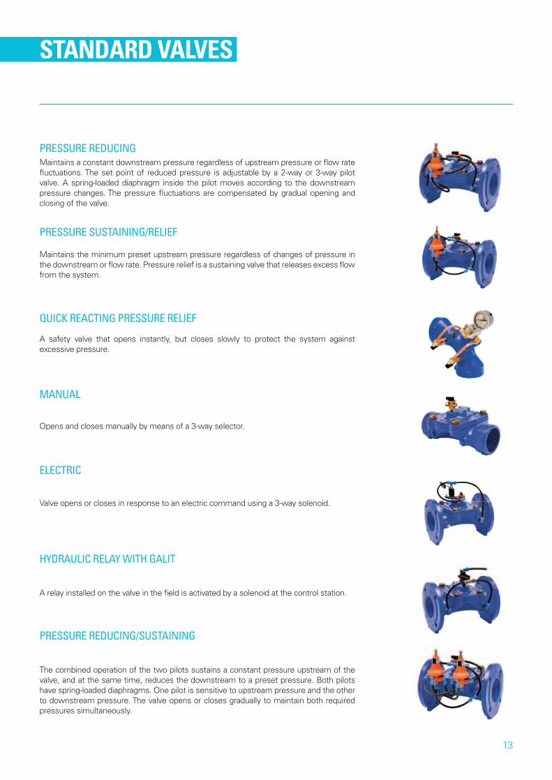
STANDARD VALVES
Maintains a constant downstream pressure regardless of upstream pressure or flow rate fluctuations. The set point of reduced pressure is adjustable by a 2-way or 3-way pilot valve. A spring-loaded diaphragm inside the pilot moves according to the downstream pressure changes. The pressure fluctuations are compensated by gradual opening and closing of the valve.
Maintains the minimum preset upstream pressure regardless of changes of pressure in the downstream or flow rate. Pressure relief is a sustaining valve that releases excess flow from the system.
A safety valve that opens instantly, but closes slowly to protect the system against excessive pressure.
Opens and closes manually by means of a 3-way selector.
Valve opens or closes in response to an electric command using a 3-way solenoid.
A relay installed on the valve in the field is activated by a solenoid at the control station.
The combined operation of the two pilots sustains a constant pressure upstream of the valve, and at the same time, reduces the downstream to a preset pressure. Both pilots have spring-loaded diaphragms. One pilot is sensitive to upstream pressure and the other to downstream pressure. The valve opens or closes gradually to maintain both required pressures simultaneously.
PRESSURE REDUCING
PRESSURE SUSTAINING/RELIEF
QUICK REACTING PRESSURE RELIEF
MANUAL
ELECTRIC
HYDRAULIC RELAY WITH GALIT
PRESSURE REDUCING/SUSTAINING

14
SPECIALTY VALVES
Used to maintain a preset water level in a reservoir or water tank. The valve is activated by line pressure according to the hydrostatic pressure. The valve stays open as long as the water level of the reservoir is below a preset level. As the water level rises, the valve gradually closes.
The valve is a normally closed electric float control valve. A float hanging over the water surface at the desired height switches the electric circuit. When the water level drops below the float, the electric circuit is switched on and opens the valve through a solenoid valve. As the rising water reaches the float level, the circuit is disconnected and the valve closes.
The flow rate through the valve is determined indirectly using an orifice plate. Normally the valve is partially open to allow a preset constant flow rate. The pressure loss across the orifice is proportional to the actual flow rate. Upon increasing pressure loss, the valve is automatically piloted to close. When the pressure drops, the valve opens and the flow rate is maintained in spite of the line pressure fluctuations or the downstream demand.
Used to maintain a preset water level in a reservoir or water tank. The line pressure activates the valve. The valve stays open as long as the water level in the reservoir is below a preset level. As the water level rises and floats the pilot’s arm, the valve gradually closes.
ALTITUDE CONTROL VALVE
ELECTRIC FLOAT CONTROL VALVE
FLOW RATE CONTROL VALVE
FLOAT LEVEL CONTROL VALVE
15
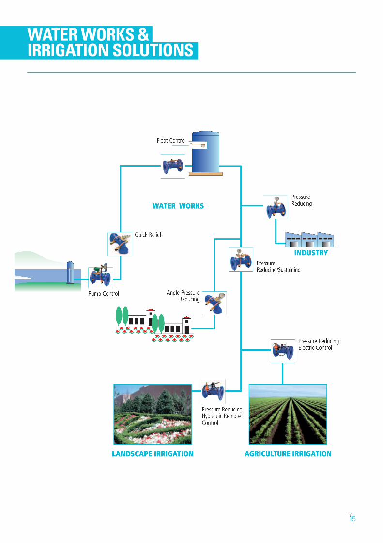
WATER WORKS & IRRIGATION SOLUTIONS

GROW MORE WITH LESS
213-217 FITZGERALD ROAD | LAVERTON VIC 3026T 03 8331 6500 | F 03 9636 3865 | E [email protected]
WWW.NETAFIM.COM.AU