neri cutting machine - welcome to nerigroup,. flame cutting machine system automatic manual editor...
TRANSCRIPT
1
Portable Plasma / Flame CNC Cutting
Machine
USER MANUAL
SNR-BD
Neri Machine Tools Pvt Ltd.
www.nerigroup.in
2
WE THANK YOU VERY MUCH FOR YOUR INTEREST SHOWN
IN OUR PRODUCT.
Before using this machine, please read the instruction carefully.
1. Open the package, please check the center unit, make sure it is not be
broken, and make sure the packing list conform to the article.
2. Please make the voltage is(AC220V±10%, and use the isolation
transformer or other isolation voltage regulator device to make sure
the system work stably. The machine must be grounded reliably when
it is working.
3. Clean up dust on a regular basis to ensure the rail and rack clean.
4. The display screen of CNC system is easily broken, pay attention to
protect it.
5. This machine should be operated by professional, with some operation
and safety train information.
6. If there is something unclear, please contact with the local dealer or
call the manufactures.
Content
1 Machinery part--------------------------------------------------------------------3
2 CNC control system part---------------------------------------------------------8
3
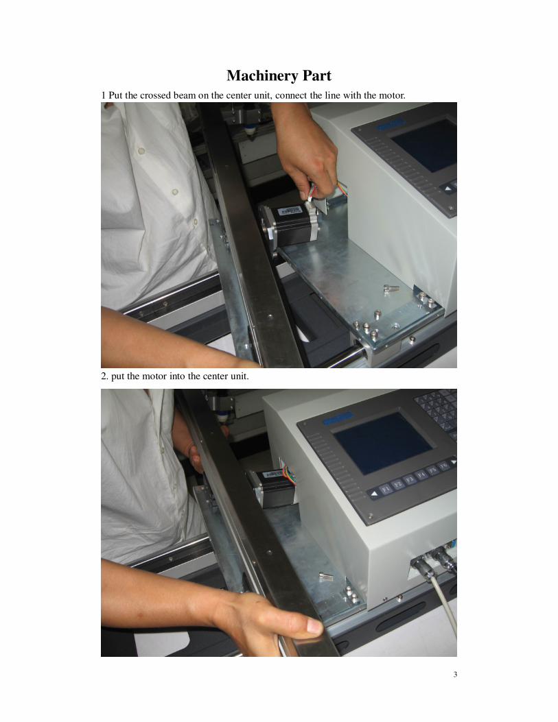
Machinery Part
1 Put the crossed beam on the center unit, connect the line with the motor.
2. put the motor into the center unit.
4
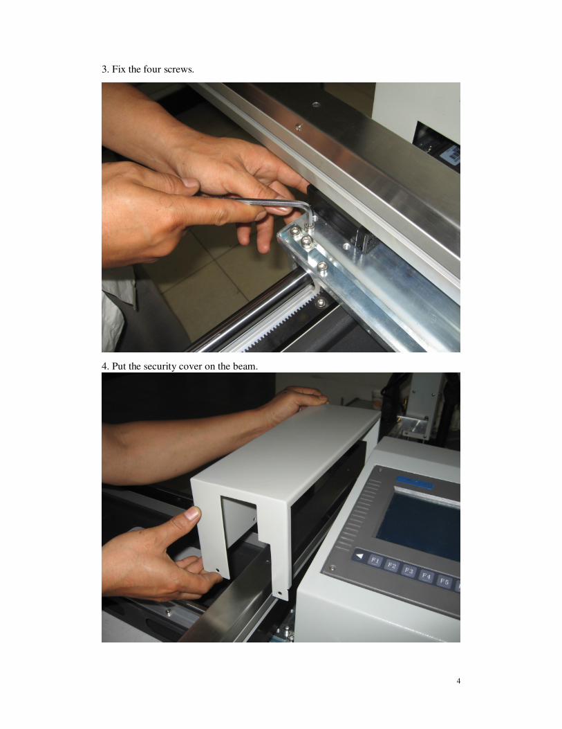
3. Fix the four screws.
4. Put the security cover on the beam.
5
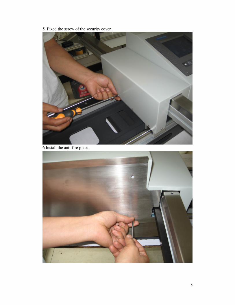
5. Fixed the screw of the security cover.
6.Install the anti-fire plate.
6
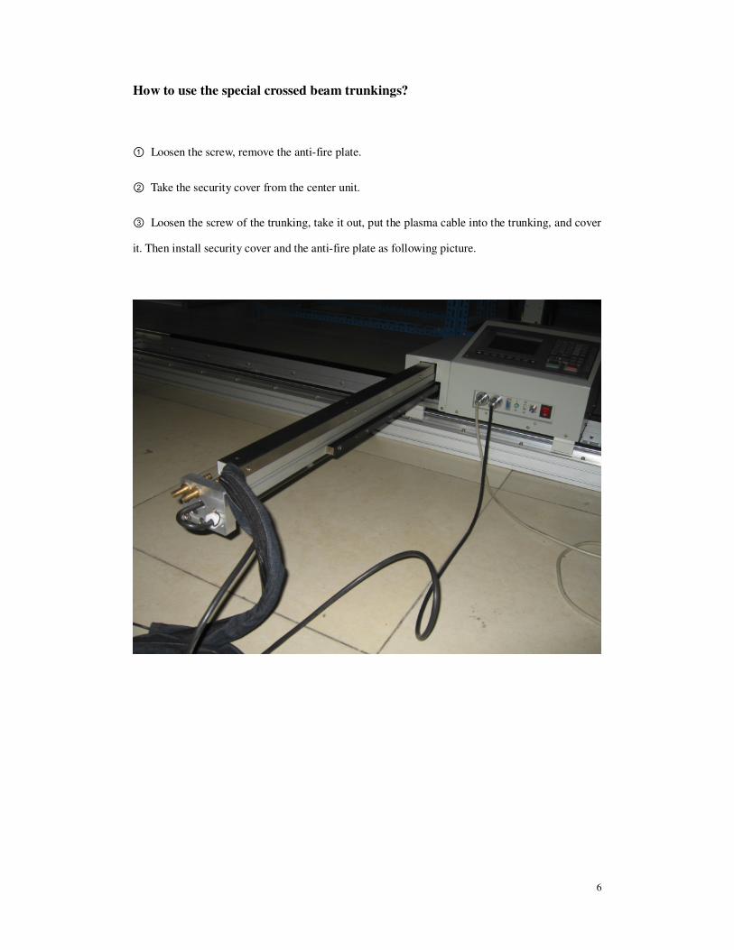
How to use the special crossed beam trunkings?
① Loosen the screw, remove the anti-fire plate.
② Take the security cover from the center unit.
③ Loosen the screw of the trunking, take it out, put the plasma cable into the trunking, and cover
it. Then install security cover and the anti-fire plate as following picture.
7
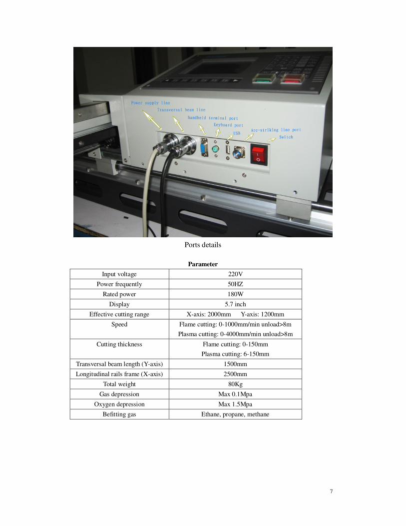
Ports details
Parameter
Input voltage 220V
Power frequently 50HZ
Rated power 180W
Display 5.7 inch
Effective cutting range X-axis: 2000mm Y-axis: 1200mm
Speed Flame cutting: 0-1000mm/min unload>8m
Plasma cutting: 0-4000mm/min unload>8m
Cutting thickness Flame cutting: 0-150mm
Plasma cutting: 6-150mm
Transversal beam length (Y-axis) 1500mm
Longitudinal rails frame (X-axis) 2500mm
Total weight 80Kg
Gas depression Max 0.1Mpa
Oxygen depression Max 1.5Mpa
Befitting gas Ethane, propane, methane

8
CNC system part
Chapter One Summarize
1.1 System features
1) 5.7 high-definition lattice LCD, Small volume, Structure compact.
2) Processing graphics dynamic/static display.
3) High speed 16-bit and 8-bit single-chip microcomputer and hardware interpolator
control. High speed running by 0.5μ equivalent 6 meters/minute.
4) Step motor high subdivision control the driver,move smoothly, low noise, the quality
improved clearly.
5) You can set begin speed and the time of rising/falling arbitrarily.
6) Supplying multiple constant loops to program simply.
7) Directly diagnose all input information of system, Convenience for you to check.
8) Multi-settings of parameter, can suit different requires.
1.2 Technology norm
1) Pulse equivalent: X-axis 0.5μ(diameter) Z-axis 1μ(or X axis 0.25μdiameter)
Z-axis 0.5μ)
2) G00 Max-speed: ≥ 6 meter/minute(X-axis 0.25μ(diameter) Z-axis 0.5μ)
3) Number of connected shaft:2 axis
4) Input coordinate scope: +/- 9999。999mm
5) Maximum lines of user program: 540 line
6) User program space: 60K
7) Number of user program: 64
8) Dimension: 300*200*85

9
Chapter Two System Operation and Function
2222.1 Operate panel keyboard illustration
`
【F1】-【F6】 Function keys: Under different operate mode, they have different definition.
【 】,【 】Triangle sign Give up and quit:Definition of the left and right key is
same.
6
3 T
。
7 8 9 U
4
V
5 I
1
J
2 M
—
S
0
G
X
Y
F
R
H
N L D
-
INS
DEL
S↓
Pgup
Pgdn
S↑

10
【INS】:Insert key under program state. Under others, it is used for increasing LCD brightness.
【DEL】:Delete key under program state. Under others, it is used for decreasing LCD brightness.
【Pgup/ S↑】:Page-up key under program state. Under automatic and manual function, it is used
for adjust cutting-gun, when press/loosen the key, cutting-gun rising/stopping.
【Pgdn/ S↓】: Page-down key under program state. Under automatic and manual function, it is used
for adjust cutting-gun, when press/loosen the key, cutting-gun falling/stopping.
【Shift】∶Space key. It is used for distinguish between upper case and lower case under program
editing state.
【 】:Enter/Effective key
【F↑】:It is used for increase speed under automatic and manual control state, increase 1%/press once
【F↓】:It is used for decrease speed under automatic and manual control state, decrease 1%/press once
Strong current control :
Ignition automatically key under manual control state.
Strong current control :
Preheat oxygen key under manual control state
Strong current control :
Acetylene open key under manual control state
Strong current control :
Cutting oxygen key under manual control state
Strong current control :
Perforation key under manual control state
Strong current control :
Close all states under automatic and manual control state
Acetylene
opened
Ignition
Preheat
oxygen
Cutting
oxygen
Perforation
General
switches
11
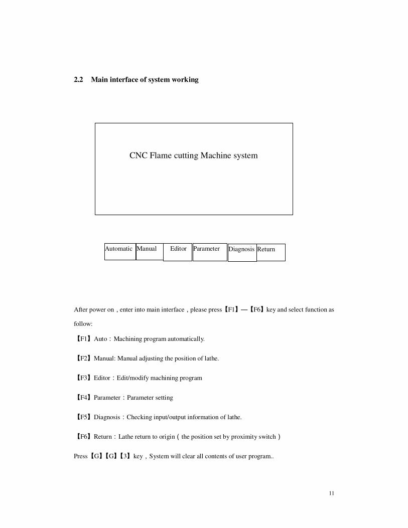
2.2 Main interface of system working
After power on,enter into main interface,please press【F1】—【F6】key and select function as
follow:
【F1】Auto:Machining program automatically.
【F2】Manual: Manual adjusting the position of lathe.
【F3】Editor:Edit/modify machining program
【F4】Parameter:Parameter setting
【F5】Diagnosis:Checking input/output information of lathe.
【F6】Return:Lathe return to origin(the position set by proximity switch)
Press【G】【G】【3】key,System will clear all contents of user program..
CNC Flame cutting Machine system
Automatic Manual Editor Parameter Diagnosis Return
12
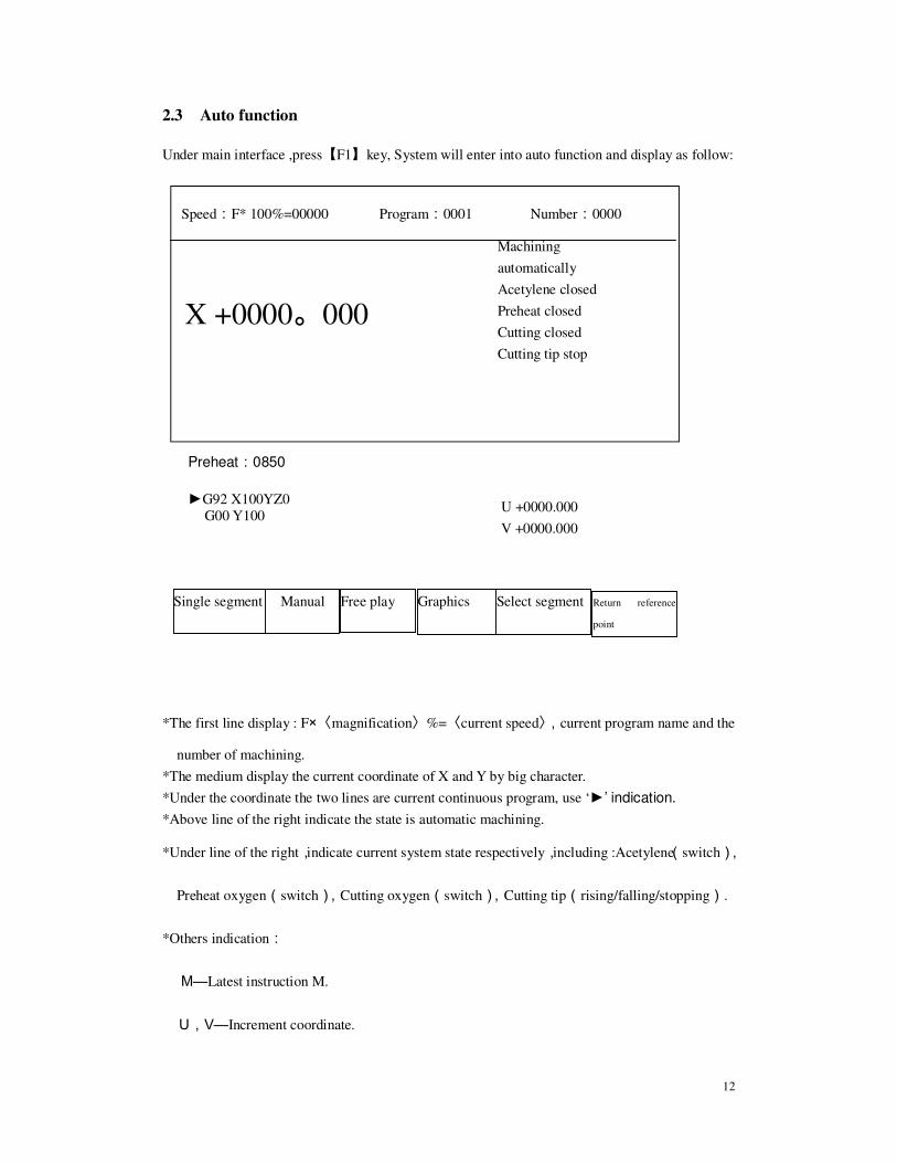
2.3 Auto function
Under main interface ,press【F1】key, System will enter into auto function and display as follow:
*The first line display : F×〈magnification〉%=〈current speed〉,current program name and the
number of machining.
*The medium display the current coordinate of X and Y by big character.
*Under the coordinate the two lines are current continuous program, use ‘►’ indication.
*Above line of the right indicate the state is automatic machining.
*Under line of the right,indicate current system state respectively,including :Acetylene(switch),
Preheat oxygen(switch),Cutting oxygen(switch),Cutting tip(rising/falling/stopping).
*Others indication:
M—Latest instruction M.
U,V—Increment coordinate.
Speed:F* 100%=00000 Program:0001 Number:0000
Single segment Manual Free play Graphics Select segment Return reference
point
X +0000。000
U +0000.000
V +0000.000
Preheat:0850
►G92 X100YZ0
G00 Y100
Machining
automatically
Acetylene closed
Preheat closed
Cutting closed
Cutting tip stop
13
Operate under automatic function
1. Press【F1】,System select single segment machining,Press 【F1】again, give up. Under
this state, Press【Startup】key once,System will run one instruction. Press【Quit】key,
give up this function.
2. Press【F2】,System enter into manual state, concrete function refer manual function section.
3. Press【F3】,System enter into free play state,Press【Startup】system working, display the
moving trace of cutting tip, But the operation of driver and I/O all closed to check whether
program is correct.
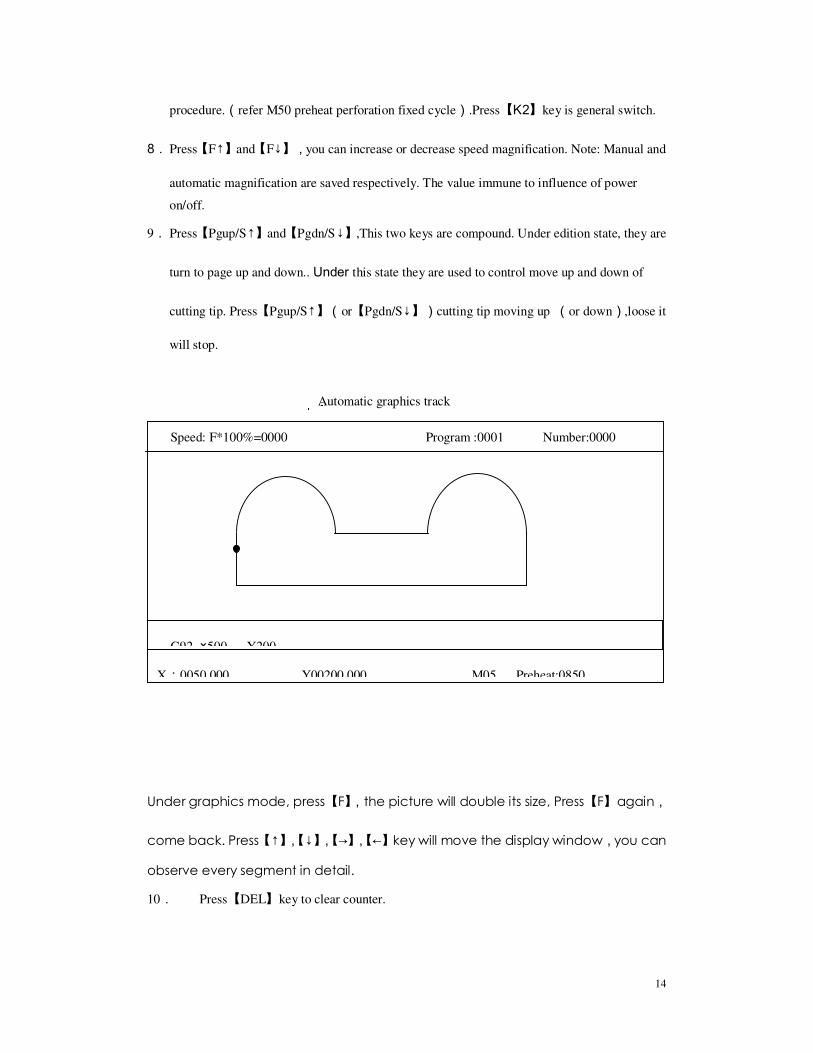
4. Press【F4】,System enter into graphics machining tracking state. (referring the picture below)
5. Press【F5】,System select arbitrary segment to machining,’►’ represent the first line
program that current running. Press【↑】and【↓】key ,you can select orderly the current
program. Press【Startup】,System will run from the selected program. Press【Quit】
will give up select segment machining. Attention: Under select segment machining state,
firstly, you should aim the cutting-gun to initiation position of program (easy aim). Press
【Startup】begin to select segment machining. When appear ‘Pause’ sign, you can manual
control the strong current switch to finish the prepare working, then press【Startup】,System
will begin to run from the selected segment.
6. Press【F6】,System will return automatically to reference point.
7. When lathes are not running, you can select strong current key to control Ignition, Acetylene
opened/closed,Preheat oxygen opened/closed, Cutting oxygen opened/closed and Cutting
tip rising/falling/stopping. Under normal machining state, the strong current keys are locked.
Attention: Press ignition key,if acetylene key is not open,please open acetylene valve
firstly ,then open ignition switch, after one ignition delay(refer Parameter----Control----
Ignition delay), close ignition switch. Press【K1】 key will run a preheat perforation
14
procedure.(refer M50 preheat perforation fixed cycle).Press【K2】key is general switch.
8. Press【F↑】and【F↓】,you can increase or decrease speed magnification. Note: Manual and
automatic magnification are saved respectively. The value immune to influence of power
on/off.
9. Press【Pgup/S↑】and【Pgdn/S↓】,This two keys are compound. Under edition state, they are
turn to page up and down.. Under this state they are used to control move up and down of
cutting tip. Press【Pgup/S↑】(or【Pgdn/S↓】)cutting tip moving up (or down),loose it
will stop.
Automatic graphics track
Under graphics mode, press【F】,the picture will double its size, Press【F】again,
come back. Press【↑】,【↓】,【→】,【←】key will move the display window,you can
observe every segment in detail.
10. Press【DEL】key to clear counter.
Speed: F*100%=0000 Program :0001 Number:0000
G92 ×500 Y200
X:0050.000 Y00200.000 M05 Preheat:0850

15
Reference point under automatic machining
Reference point is initial point of machining program(set by G92).One program run once
(include free play), Reference point will be saved automatically(Also set by parameter).
Once reference point is set, orientation of reference point is very easy, as follows:
1)Please aim the knifepoint to special position of steel plate that waiting for cut(know
coordinate), set the current coordinate.
2)Under automatic or manual mode, if select return reference point function, system will
automatically return to reference point.
Startup under automatic machining
After all prepare work is ok, there are two means to startup the automatic machining program.
1.Press【Startup】.
2.Press outside“startup”button.(refer chapter 6.1 “outside input interface”)
Control and error compensate under automatic machining
After automatic machining beginning, only these keys are effect:
1.【Pause】: Press this , system will decrease speed till stop. Execute instruction M according to
the set of G61 to keep the current display contents. If press【Startup】, system will keep on running.
Under pause state, if find deviation of dimension, you can press【F2】key to enter into manual state
(in inch state automatically, increment is 0.01mm),Operator press direction key to adjust the
position of knifepoint, its move be considered compensation. Adjustment finished, press【Startup】
system will neglect compensation movement and keep on running according to before adjustment.
If press 【Quit】, system will return to main picture.
Error compensation under pause state is reference point’s compensation in fact.
2.【F↑】,【F↓】Moving axis adjust speed key: Increase or decrease speed magnification, change
1% once.

16
3.【Pgup/S↑】,【Pgdn/S↓】Control cutting gun rising or falling ,Press key, cutting gun rising
or falling, loose it will stop.
4.【Stop】::::Outside button(refer chapter 6.1 “outside input interface”),Signal can derive
from input port. All stop when this key is effect.
Return and renew machining according to original track
During machining, because of cutting incompletely, need return and renew machining, You
can deal with as follow:
1.Press【Pause】, system will decrease speed till stop and display"pause"sign. Prompt
(Graphics mode)"F2manual F6return",Press【F2】can enter into manual compensation
function(refer below),press【F6】can enter into return and renew machining function.
If select【F6】, System will hint:
Return<-<-<-<- ->->->->forward
Indication: Press【←】, System will return along original trace. Press【→】, System will forward
along original trace base of return. During return, if reach position that want to return, You can
press【Pause】again, repeat the above-mentioned procedure, select again keep on returning or
forward.
2.You may press【Pause】 again when system get to the return position,After system stop
Steady, you can press the strong current key correspondingly(like Preheat perforation, open
cutting oxygen etc.),Press【→】again, and select machining forward.
3.Above-mentioned operate can run repeatedly till get the satisfactory effect.
Break recover and power cut disposal
When system pause by man-made, it will save automatically the current working trace
(cutting tip’s position) as a break. This break will be saved forever, regardless power off. Power on
again or enter into automatic mode, if only the current program is not changed you can press【G】
key to resume break. When find the break, system will hint "pause"state, You can press the
strong current function key correspondingly (such as preheat perforation, open cutting oxygen
etc.), Press【Startup】again, system will keep on running from break’s position.
17
After machining pause, if you want to quit automatic state and enter into manual state to
move cutting tip(whatever how much),When press【G】key to begin resuming break, system will
move the cutting tip to the position of break firstly, then resume break. Of course, if you changed
the current coordinates by hand, the break will not be resumed normally.
If during machining, you encounter failure of electricity, you can enter into
automatic mode firstly after get back electric power. Press【F3】 key will set the current
coordinate as break and recover like above-mentioned. Attention: This moment you must not move
the cutting tip or set the current coordinate.
Only pause operation can generate break.
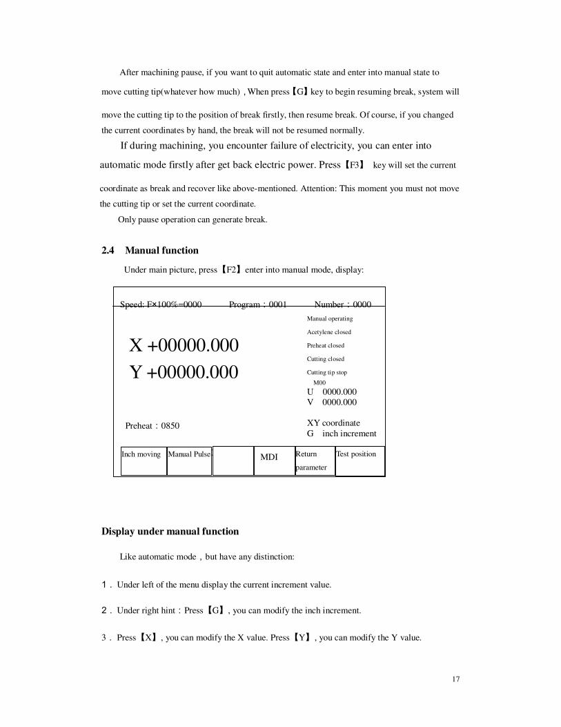
2.4 Manual function
Under main picture, press【F2】enter into manual mode, display:
Display under manual function
Like automatic mode,but have any distinction:
1. Under left of the menu display the current increment value.
2. Under right hint:Press【G】, you can modify the inch increment.
3. Press【X】, you can modify the X value. Press【Y】, you can modify the Y value.
Speed: F×100%=0000 Program:0001 Number:0000
Preheat:0850
Inch increment:0001.000
Inch moving Manual Pulse
MDI
Return
parameter
Test position
X +00000.000
Y +00000.000
Manual operating
Acetylene closed
Preheat closed
Cutting closed
Cutting tip stop
M00
U 0000.000
V 0000.000
XY coordinate
G inch increment
18
Operate under manual function
1. Press【↑】and【↓】to adjust the position of X axis,Press direction- key correspondingly. The
X axis will run by speed the maximum speed limitthe maximum speed limitthe maximum speed limitthe maximum speed limit* Manual magnification. Press【→】and
【←】to adjust the position of Y axis. Press direction-key correspondingly, The Y axis will
run by speed the maximum speed limitthe maximum speed limitthe maximum speed limitthe maximum speed limit* Manual magnification.
2. Press【F1】, system will enter into inch moving state, Press the direction-key once, Motor will
move one inch increment correspondingly. Press【F1】again, return to continue state. Press
【G】key can change the inch increment.
3. Press【F2】,system will enter into manual pulse mode, display as follow:
4.Press【F4】,system will select MDI function,Under this mode,You can directly input single
segment program, such as:
G01 X100 Y200
After input one line, press【Enter】key to run at once. Press【Quit】key to cancel. MDI MDI MDI MDI
mode supports various G、M、S instructions. Note: The MDI instruction inputted will
be saved till modified or power off.
Speed:F×100%=0000 Program:0001 Number:0000
X axis Y axis
1.00
0.10
0.01
0.002
X +00000.000
Y +00000.000
Manual operating
Acetylene closed
Preheat closed
Cutting closed
Cutting tip stop
M05
U 0000.000
V 0000.000
XY coordinate
Enter into manual pulse mode,
Press【F1】and【F2】 to select
X or Y axis.
Select valid weight:
【F3】- 1.00mm / pulse
【F4】- 0.10mm / pulse
【F5】- 0.01mm / pulse
【 】
19
5.Press【F5】,System will control cutting tip return to reference point.
6.Press【G】will change the value of inch increment, hint: input increment value, then press enter
key, this value will be saved till changed or power off.
7.Press【X】key to change value of X .hint: input coordinate of X(Y)axis, then press enter key,
the coordinate of X and Y are changed at once; Press【Y】key to change value of Y .hint: input
coordinate of Y axis, then press enter key, the coordinate of Y are changed at once
8.Press【F6】key,system enters into test-position function. Test-position is testing the precision
distance from the current position of cutting tip to the origin of machine tool. Concrete usage:
Firstly, You should aim the cutting tip to a special point(such as reference point),test the
current coordinate and modified(press“X/Y”),Press【F6】key, cutting tip begin to return to
origin of machine tool and save it as machine’s origin of parameter. Return-position is same to
test-position from shape, but their results are not same: Return-position is that send the origin
value of machine tool to current coordinates , but test-position is that send the current
coordinate to origin of machine tool.
9.Press【F↑】and【F↓】,you can adjust the manual magnification. Note: Manual and automatic
magnification are saved respectively till changed and the value immune to influence of power
off.
10.Press【Pgup/S↑】,【Pgdn/S↓】and strong-current key ,their usage is same to
auto mode.
2.5 Parameter set
Under main working picture, Press【F4】can enter into parameter set function.
Displaying:
Parameter set
Speed Adjustment Control System Save

20
Every function item save parameter as follow:
Speed---- Start speed, Adjust time,Max speed.
Adjustment---- Software limit position,Origin,reverse clearance,reference point
ControlControlControlControl----Machining speed limit, Ignition delay, Preheat delay, Cutting gun rising delay,
Cutting gun falling delay, Perforation cutting gun rising delay, Perforation cutting gun falling
delay. System----Each axis’s electric gear, Driver’s subdivision. Save----Save the changed parameters to parameter area.
2.5.1 Speed parameter
Press【F2】 and select (refer picture below)
2.5.2 Adjust parameter
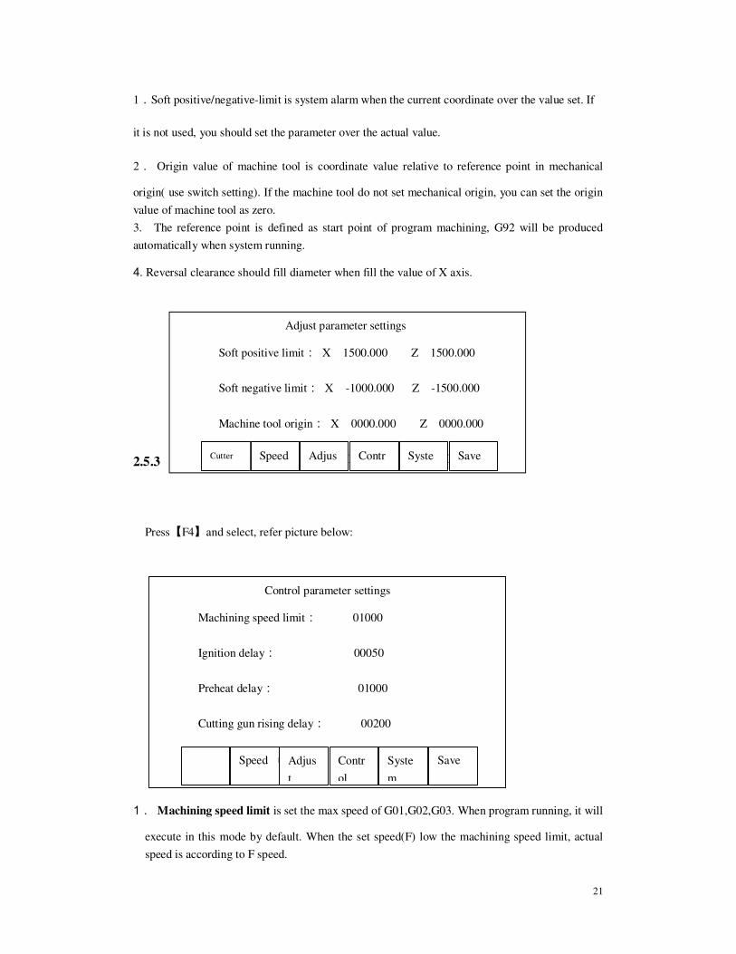
Press【F3】 and select adjust parameters(refer picture below),Among these :
Speed parameter setting
Start speed: X 00250 Y 00250
Adjust time: X 00040 Y 00040
Max speed limit: X 05000 Y 05000
Note:time’s unit is one percent second
Cutter Speed Adjust Control System Save
Speed
Tim
e
Start speed
Adjust time Adjust time
Max speed
Start speed
Means of each parameter refer left
picture:
Start speed and max speed ‘s unit
is mm/minute
time’s unit is one percent second
00040 express 0.4 second.
The max speed limit regulate the
max speed of by-hand and G00。
21
1.Soft positive/negative-limit is system alarm when the current coordinate over the value set. If
it is not used, you should set the parameter over the actual value.
2. Origin value of machine tool is coordinate value relative to reference point in mechanical
origin( use switch setting). If the machine tool do not set mechanical origin, you can set the origin
value of machine tool as zero. 3. The reference point is defined as start point of program machining, G92 will be produced
automatically when system running.
4. Reversal clearance should fill diameter when fill the value of X axis.
2.5.3 Control parameter
Press【F4】and select, refer picture below:
1. Machining speed limit is set the max speed of G01,G02,G03. When program running, it will
execute in this mode by default. When the set speed(F) low the machining speed limit, actual
speed is according to F speed.
Adjust parameter settings
Soft positive limit: X 1500.000 Z 1500.000
Soft negative limit: X -1000.000 Z -1500.000
Machine tool origin: X 0000.000 Z 0000.000
Reversal clearance: X 0000.000 Z 0000.000 Cutter Speed Adjus Contr Syste Save
Control parameter settings
Machining speed limit: 01000
Ignition delay: 00050
Preheat delay: 01000
Cutting gun rising delay: 00200
Cutting gun falling delay: 00180 Speed Adjus
t
Contr
ol
Syste
m
Save

22
2. Ignition delay----Keep up the electrified time of high-voltage ignition.
3. Preheat delay----It is the preheat time when steel plate perforation, preheat time is adjustable.
When preheat perforation, press【Pause】key, can delay automatically 150 seconds. Press【Startup】
will stop preheating and save the actual preheat time to parameter.
4. Cutting gun rising delay----It is used usually before G00 transfer .The cutting gun rise to
suitable height in order to avoid knocking between cutting gun and steel plate.
5.Cutting gun falling delay----Contrary to the above item, the cutting gun fall to suitable height.
After transfer the G00,you should down the cutting gun before machining. Because of gravity, the
time of falling is shorter than rising.
6.Perforation cutting gun rising——Under fixed cycle of preheat perforation, cutting gun rising
rapidly and perforation cutting gun rising delay. This moment open cutting oxygen and cutting gun
begin falling and perforation cutting gun falling delay. Cutting gun rising before open cutting
oxygen in order to avoid jamming the cutting gun’s gate when open cutting oxygen.
7.Perforation cutting gun falling——Its usage refer the above item. Under fixed cycle of
preheat perforation, it will finished after cutting gun falling and perforation cutting gun falling
delay. Because of gravity, the time of falling is shorter than rising.
2.5.4 System parameter2.5.4 System parameter2.5.4 System parameter2.5.4 System parameter
Press【F5】and select, refer picture below:
Electric gear formulaElectric gear formulaElectric gear formulaElectric gear formula:
N/M=Micrometer thread pitch *1000/(360*subdivision/Stepping
angle*Transmission ratio)
Explaining:N—Numerator after simplified.
System parameter settings
Electric gear: X N 00000 M 00000
Electric gear: Z N 00000 M 00000
Subdivision: X 0040 Z 00040
Cutter Speed Adjus
t
Contr
ol
Syste
m
Save
23
M—Denominator after simplified.
Micrometer thread pitch’s unit:mm;
Stepping angle unit:angel;
Transmission=Z1/Z2=Motor’s rotate speed/spindle rotate speed.
Formula can also be written:
N / M = Pulse equivalent weight = Micrometer thread pitch*1000/Pulse number of
step motor that spindle rotate one circle
2.6 Program editing
This system program edit have two districts: Machining program and user program, refer
picture below. There are battery to protect data from missing.
Machining program edit area : Current working program area ,only one current program.
Once machining program be added from user program area to machining area(or new program),
Regardless of new or modification executed in edit area and need not save program by saving
means. Only when need change new program, the current program is saved to user program area
by【【【【F3】】】】,New or add new machining program【【【【F2】】】】 from user program area.
Program space: 64K bites.
Number of user program: Save 64 user programs at best, but affected by the space of user
program, When the user’s program is long, the number of user program are saved will reduce
relatively. When the user’s program is short, the number of user program are not over 64, even
though there have space.
Length of machining program: The max line is 540 that system supported.
Under main menu,press【F3】,you can enter into edit function, refer the picture below:
001: G92 X0 Y100
002: G00 X-20
003: G01 X100 Y30
004: M03
005: G04 L100
006:M02
Mach
inin
g area
Machinin
g program
edit area
User
program
area

24
There are 6 items after enter into program edit state, function as follow:
1) 【【【【FFFF1111】】】】-------- New program,Clear the area of program edit and start editing new machining
program.
2) 【【【【F2F2F2F2】】】】-------- Call program,Call the existent program to the area of machining program edit
and you can modify it.
3) 【【【【F3F3F3F3】】】】-------- Save the program of machining edit area to user’s program area.
4) 【【【【F4F4F4F4】】】】-------- Delete existent program from user’s program area.
5) 【【【【F5F5F5F5】】】】--------Delete the line of current edit program.
6) 【【【【F6F6F6F6】】】】-------- You can receive or send user program to computer or CNC system.
2.6.1 Edit2.6.1 Edit2.6.1 Edit2.6.1 Edit
Enter into edit function, the current machining program will be displayed. You should pay
attention to the several items as follow: 1) The faceplate keys have double kinds. One is compound key, the other is single function
key. Usually press the compound key is the value of lower case, if you firstly press
【Shift】,then press compound key is the value of upper case, this function is effect only
under program editing state.
2) Cursor move up and down: When cursor move up and down, the cursor will lie in the first
line automatically. The cursor will move one line each press. When the cursor move out
the first line of screen, if the front have program again, the screen will roll one line; When
cursor move out the last line, if the last have program, the screen will roll one line
backward.
3) Cursor move left and right: The cursor will move one character each press. When move
to the first line, still press left is not effect. When move to the last, still press right is not
effect.
4) Press【F↓】,Cursor will move right to last line.
5)Turn page up and down: Press【Pagup / S↑】or【Pagdn / S↓】,the screen will turn page
forward or backward.
New Add Save Delete Delete line Transfer

25
6) During machining program, the number is generated automatically.
7) Note of machining program: The note have important effect on add sub-program and
transfer sentence when source program editing. When the line’s first character is”—“or“。”,
show this line is note.
8) This system’s minimum resolution is 0.001mm。
2.6.22.6.22.6.22.6.2 NewNewNewNew
Press【F1】,select New.2
System hint: Are you continue?
If press【Enter】,Clear the current editing area; if press【Quit】,give up producing new program.
2.6.3 2.6.3 2.6.3 2.6.3 Call program
Press【F2】and select the program that be called user’s program area. The system will listed the
existent program’s name, and the cursor will stay the current name of program. Move the
cursor , you can select various program. After press【Enter】,The selected program will be called
into editing area; If press【Quit】,it will give up the function of calling.
2.6.4 Save program2.6.4 Save program2.6.4 Save program2.6.4 Save program
Press【F3】select save function, the system will hint:
Program name:0001
The system display the current program name, you can modify it. If press【Enter】,it will save
the program of machining edit area to the user’s program area by the selected name. If press
【Quit】,it will give up the function of saving. Note: The document name is only four bits number.

26
2.6.5 Delete program2.6.5 Delete program2.6.5 Delete program2.6.5 Delete program
Press【F4】and select deleting the program of user program area. The system will listed the
existent program’s name, and the cursor will stay the current name of program. Move the cursor,
you can select various program. After press【Enter】, The selected program will be deleted from
user editing area; If press【Quit】,it will give up the function of deleting.
2.6.6 2.6.6 2.6.6 2.6.6 Transport program
Press【F6】and select transport function. The system supports RS-232 communication. The
program that transported is managed in machining edit area. Step as follow:
1. Connect well two machines that will transport program by cable.
2.Ensure the receive machine have no documents (if have, please first save it) that you want to
reserve in machining edit area. Select again the function of transport—receive. The receiver
should is receiving state.
3.On the program transporter, Call the program that will be sent out to machining editing area,
then select Edit————Transport————Send out。
4.When transporting finished,Save the received programs.
Chapter three Instruction system
3.13.13.13.1 Programming symbol explanation
Every action of CNC machining should run according to regulated program. Every
machining program is composed of some instruction-segment, Every instruction-segment is
composed of some function-word. Every function-word must start by character, followed by
parameter.
27
The definition of function-word::::
N The number of instruction-segment
G Prepare function
M Auxiliary function
S Principal axis
L Cycle frequency
X X axis (diameter) definitely coordinates
Y Y axis definitely coordinates
U The increment of X axis relatively current position
V The increment of Y axis relatively current position
I when machining arc, Value of coordinates that the center of a circle subtract
the value of start point that X axis.
J When machining arc, Value of coordinates that the center of a circle subtract
the value of start point that X axis.
R Specify arc radius
F Specify machining speed, use for G01、G02、G03
Note 1::::Underneath explanation, Appointment as follows:
X[U]n -- It represent X or U, n represent value, but only appear once.
Y[V]n --It represent Y or V, n represent value, but only appear once too.
PPn -- Random axis combination, include one axis at least, it also can include
two-axis.
Note 2::::Executing order, the up line will be executed first than next (except Jump and Call
sub-program instruction),In the same program, M, S and T is executed first than G.
3.2 Coordinates system
This system adopt standard coordinates system, that is right hand Descartes coordinates
system, as follows:

28
3.3 G((((Basic prepare instruction))))
1) G92 reference point setting
When you set the program running, you must put the coordinate value of machining start
(reference point)to the start of program, and set use definitely coordinates.
Format: G92 Xn Yn
If the content of X and Y don’t follow G92, Current coordinates of X and Y be regarded as
reference point. When use the origin of machining tool to locate, the content of X and Z don’t
follow G92.
2) G00 dot moving
This instruction can carry out getting to specify position quickly. When two axis all have
displacement, System will move straight from the start to destination by the most limited speed
multiply magnification. When G00 exerting,it will be affected by speed magnification.
Format:::: G00 X[U]n Z[W]n
or G00 PPn
+
Y
+X
+Y
+280
+120
+X Position of current cutting-gun
Position of anticipate cutting-gun
Example:
G92 X0 Y0
G00 X120 Y280
(or G00 U120 V280)
M02

29
3) G01 Cutting along straight line
This instruction can carry out cutter get to straight specify position, As cutting instruction,
Single axis or double axes can move along straight interpolation. the speed of process is specified
by F instruction.
Format:::: G01 X[U]n Z[W]n [Fn]
or G01 PPn [Fn]
4) G02/G03 Arc cut
This instruction use for arc interpolation, it is divided into sequence arc G02(anticlockwise),
inverse arc 03(clockwise). For the setting of direction refer the picture below:
Format:G02[03] X[U]n Y[V]n In Jn [Fn] or::::G02[03] X[U]n Y[V]n Rn [Fn]
G02[03]PPn In Kn [Fn] or:::: G02[03] PPn Rn [Fn]
+
+23
5
+95
+8 +200
+
Example:G92 X0 Y0
G00 X200 Y95
G01 X80 Y235
(or G01 U-120 V145)
M02
The current position of
cutting-gun
The anticipative position
of cutting-gun

30
Illustration:
� The value of I and J is increment that relative to start point of X and Y direction
center.(Center subtract start point).
� R is radius.(R is positive value, When arc≤180°, you can use R to represent radius.
� If you specified I,J, no R. If you specified R, no I and J.
5) G04 Pause / delay instruction
This instruction can be used for set time delay, When program run this instruction, The program
will delay according to the L defined. Unit is second.
Format: G04 Ln
Example:G04 L2.4 (delay 2.4 second)
When during run G04, Press【Start】key, it will stop delay, continue to run program that behind
G04.Press【Quit】key, it will stop the run of current program.
6) G26,G27,G28 return to reference point
Implement this instruction, Cutter can return to reference point automatically.
Format: G26 XXXX axis return to reference point
G27 ZZZZ axis return to reference point
G28 XXXX and Z axis return to reference point simultaneously
7
50
+100 O +40 +16
+
+X
G0
O’
Example(G02):
G92 X0 Y0
G00 X40 Y50
G02 X160 V0 I60 J20
G28
M02
Example(G03):
G92 X0 Y0
G00 X40 Y50
G03 X160 V0 I60 J20
(or G03 X160 V0 R63.25)
G28
G0
The position of current
cutting-gun.
The position of anticipative
cutting-gun.

31
Example: G28 (X and Z axis return to reference point simultaneously, equal to G00)
7) G97 Jump sentence
This instruction can make program jump automatically to specified section running.
Format: G97 Nn
Example: N000 G92 X100 Y100
N001 G00 X70 Y80
N002 G01 W-30
。。。。
N151 G28
N152 G97 N1 (jump to instruction that No N001 running)
M02
The above program is a endless loop, usually it is used for check the stability of system
and mechanism.
8)))) G98/G99 Call sub-program
The use of G98 and G99 need cooperating, G98 is call instruction and G99 is return
instruction.
Symbol:::: G98 Nn ((((N is the first segment number of subprogram that will
be called))))
G99
Example: N001 G92 X100 Y100
N002 G00 X50 Y80
N003 G98 N20 - Call first subprogram
N004 G01 W-10
N005 G98 N25 - Call secondly subprogram
。。。。
N019 M02 - Program finished
N020 G02 U0 V-20 R10 - The first subprogram
N021 G03 U0 V-20 R10
N022 G99 - The first subprogram return
N023 * - Two note lines, adjust the position of subprogram
N024 *
N025 G01 U2 V-1 - The second subprogram
N026 G01 V-5
N027 G98 N20 - Subprogram nesting, call subprogram one.
32
N028 G01 V-5
N029 G99 - Subprogram two return.
Note: Subprogram can call subprogram(named nesting), System permit subprogram that have five
nesting.
8) G22/G80 Cycle sentence
This instruction can be used to run program cycle, G22 is the start that cycle body, and specified
the cycle times L. G80 is the finished sign of cycle body. This instruction can nesting cycle, but
don’t allow over five. G22 and G80 make up a cycle body.
Format: G22 Ln_ ((((L is the specified times))))
Cycle body
G80 ((((Sign of cycle body finish))))
Example: N000 G92 X100 Y100
N001 G00 X60 Y80
N002 G22 L5 - First layer cycle starting
N003 G00 V50 U-25
N004 G22 L5 - Twice layer cycle starting
N005 G01 U5 V-10
N006 G80 - Twice layer cycle finish
N007 G80 - First layer cycle finish
N008 G28
N009 M02
9) G81 Machining piece add one
This instruction can make the machining piece add one.
Format: G81
3.4 M function and configuration files
1) M function
M00 Program pause instruction, Press【【【【Start】】】】, program will continue running.
M02 Program finish instruction, program is waiting state after run this.
M30 Same to M02
M10/M11 Acetylene valve on-off,M10(On),M11(Off)
M12/M13 Cutting oxygen valve on-off,M12(On),M13(Off)
M14/M15 Cutting-gun rising on-off,M14(On),M15(Off)

33
M16/M17 Cutting-gun descending on-off,M16(On),M17(Off)
M24/M25 Preheat oxygen valve on-off,M24(On),M25(Off)
M20/M21 Ignition on-off M20(on),M21(off)
M50 Preheat perforation fixed circle, operate order as follow:
1.If acetylene valve isn’t opened, turn on acetylene ignition;
2.Cutting-gun descending(Cutting-gun descending delay, referM71);
3.Open preheat oxygen valve, start preheat delay. If the time of preheat is not
enough, you can press【【【【Pause】】】】, the preheat time will delay automatically 150 seconds.
If preheat is ok, you can press【【【【Start】】】】to finish preheat delay, and the pre-heat time will
be saved automatically to preheat delay parameter.
4.Cutting-gun rising (perforation cutting gun rising delay)
5.Open cutting oxygen valve, at the same time cutting-gun descending(perforation
cutting-gun delay) and start to run the latter program.
M51 Close cutting fixed cycle, opposite to M50. Operate order as follow:
1.Colse cutting oxygen valve(M13);
2.Cutting-gun rising (Cutting-gun rising delay, refer M70).
M51 is often used before G00, put up cutting-gun to shift position and avoid
colliding with steel plates.
M52 Ignition fixed cycle, operate order: open acetylene valve(M10) and high-voltage
ignition(M20), delay “ignition delay”, close high-voltage ignition(M21).
M70 Cutting-gun rising fixed cycle, operate order: open cutting-gun rising
on-off(M14),delay “cutting-gun rising delay”, close cutting-gun rising on-off(M15).
M71 Cutting-gun descending fixed cycle, operate order: open cutting-gun descending
on-off (M16), delay “cutting-gun descending delay”, close cutting-gun descending
on-off (M17).
M80 General switch, after execute M80, all outputs will be closed.
M16/M17 Control output 4# on-off,M16(on),M17(off)
M18/M19 Control output 6# on-off,M18(on),M19(off)
M22/M23 Control output 7# on-off,M22(on),M23(off)
M40/M41 Control output 9# on-off,M40(on),M41(off)
M26/M27 Control output 10# on-off,M26(on),M27(off)
M28/M29 Control output 11# on-off,M28(on),M29(off)
M32/M33 Control output 12# on-off,M32(on),M33(off)
M34/M35 Control output 13# on-off,M34(on),M35(off)
M36/M37 Control output 14# on-off,M36(on),M37(off)
M38/M39 Control output 15# on-off,M38(on),M39(off)
M42/M43 Control output 16# on-off,M42(on),M43(off)
34
2) Output configuration files
In order to adapt for different user’s request of output form, This system adapt configuration
files to confirm:
1. Specified M function after G60, it will output pulse signal. At the same time D parameter
will specify pulse width. If G60 is not specified M function, it will output electric level
form..
2. M function that behind G61 instruction is need executed after carry out the Pause
instruction.
3) Output configuration files sentence contents:
1.G60 ::::Specified M instruction that followed is pulse output.
Format: G60 Mn。。。 Dn
Mn – M function( You can specify eight M function at most or none.)
Dn – Delay time(uniform delay time of above specified M function), unit: second, default
value: 0.13 second.
Example: G60 M03 M04 M05 M10 M11 M12 M08 M09 D0.23
Explain: Specified M03 M04 M05 M08 M09 M10 M11 M12. Output is pulse signal that 0.23
second.
2.G61 ::::Specified the followed M instruction be used after Pause.
Format: G61 Mn。。。。。。。。。。。。
Mn – M function(You can specify eight M function at most or none).
Example: G61 M05 M12 M22 M04 M09 M78
Explain: After system execute pause operation, requiring execute M05 M12 M22 M04 M09 output.
M78 express resuming automatically pause’s output state when start again after pause.
4)The usage of output configuration files:
(Only execute once, if not amend the output form, it is not need to execute again.)
1.Enter program editing function.
2.Compile configuration files that include G60 and G61, named file again and save. 3.Entering automatic function, execute configuration files.

35
Chapter Four System diagnosis
Under main function menu, Press【F5】and enter System diagnosis function, refer
picture below:
System diagnosis display the opened hardware resource of current system. Under the
pictudre of system diagnosis, you can check the interface that followed:
1. Output checking: Cursor move to random position of 16 dots photo-electricity isolation
output. Use “0 and1” to change output state of electric level. 1 express set-bit, 0 express
cancel. The definition of other output ports, please refer to 6.2 chapter.(output ports
definition).
2. Input checking: Display the input state of current 16 dots photo-electricity isolation. ‘1’
express set-bit. ‘0’ express this port have no set-bit. The definition of other input ports, please
refer to 6.1 chapter.( input ports definition).
3. Keyboard checking: Press random key of 44 keyboard and display the value.
4. Coder checking: Turn coder, the screen display coding angle signal cumulate value, rotate
signal and checking thread No.
5.... Hand-pulse generator checking: Turn hand-pulse ,display direction electric level and the
number of input pulse.
Output: M10 M12 M14 M16 M20 M18 M22
M24
0 0 0 0 0 0 0
0
M40 M26 M28 M32 M34 M36 M38
M42
0 0 0 0 0 0 0
0
Input: >X+ X-< >Y+ Y-< HAD STP PAU
STA
1 1 1 1 1 1 1
1

36
Chapter five System inside connectSystem inside connectSystem inside connectSystem inside connect
5.1 System inside structure picture
5.2 System power supply
Double SCM circuit
LCD control circuit
Keyboard receiving
Hardware interpolation machine
Battery circuit
Photo-electricity
isolation input/output
CNC main-board
+24Vpower
LCD power
LCD be in a
poor light
Signal
shifting
Shifting
board
LCD
Keyboard Output
Input
Coder
Motor
Hand-pulse
RS232
communication
Transformer
On-off power
source
On-off power source
7A / 5V
7824
+24V
Connect shifting board
Connect CNC main board
+5V
LCD high-level inverse converter Connect LCD be in poor
light
LCD power source
DC / DC
LCD brightness
adjust
AC220V
AC22V
AC380V
Digital
potentiometer
+ -
37
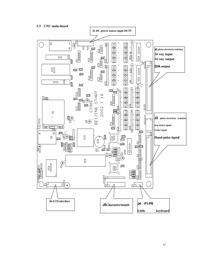
5.3 CNC main-board
J1 DC power source input DC5V
J2 J2 J2 J2 photo-electricity isolation
16 way input
16 way output
D/AD/AD/AD/A output
J3 J3 J3 J3 photo-electricity isolation
step motor signal
Coder signal
Hand-pulse signallll
RS232 RS232 RS232 RS232
J4 F1J4 F1J4 F1J4 F1----F6F6F6F6
Little keyboard
J5J5J5J5Character/numb
er
J6 LCD interface

38
5.4 Signal shifting board
J7 LCD inverter
interface

39
Chapter six System outside connect 6.1 Outside input interface
1)1)1)1) Urgent stop / / / / Start ////Pause signal input
Urgent stop/Stop/Pause commonly use mechanical on-off, in order to avoid interfere, we
usually use normally off contact of mechanical on-off, according to the followed picture to
connect.
Attention:::: System require urgent stop, start ,pause and the logic of margin is uniform, this is all
connect to normally on or normally off (in common use). After system start, it will check the
state of start bit automatically and as control base. So, if don’t connect external start on-off,
the corresponding start-bit should be connected to 24V ground (simple to connect to normally
off contact) or connect none(simple to connect to normally on contact).
2) Margin / origin signal input
Margin/origin usually use mechanical on-of or double thread magnet on-off and NPN, PNP
Hall on-off. Toward use mechanical on-off or double thread magnet on-off , you can connect
according to as the above item 1). If use NPN or PNP model Hall on-off, you can connect
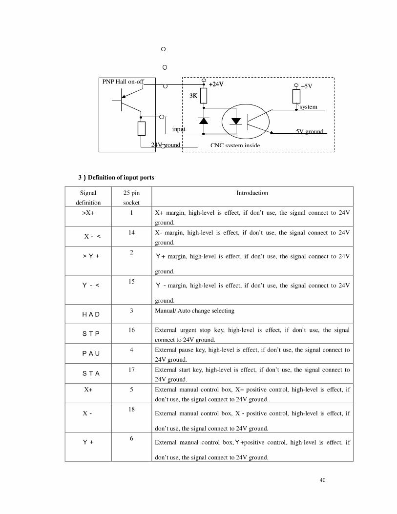
according to the picture below.。
+24V
Input
3K
5Vground
`System input
CNC system
Normally off contact
24Vground
+5V
+24V
input
3K
5Vground
`system input
CNC system inside 24Vground
+5V
3K
NPN Hall on-off
40
3))))Definition of input ports
Signal
definition
25 pin
socket
Introduction
>X+ 1 X+ margin, high-level is effect, if don’t use, the signal connect to 24V
ground.
X-< 14 X- margin, high-level is effect, if don’t use, the signal connect to 24V
ground.
>Y+ 2 Y+ margin, high-level is effect, if don’t use, the signal connect to 24V
ground.
Y-< 15 Y-margin, high-level is effect, if don’t use, the signal connect to 24V
ground.
HAD 3 Manual/ Auto change selecting
STP 16 External urgent stop key, high-level is effect, if don’t use, the signal
connect to 24V ground.
PAU 4 External pause key, high-level is effect, if don’t use, the signal connect to
24V ground.
STA 17 External start key, high-level is effect, if don’t use, the signal connect to
24V ground.
X+ 5 External manual control box, X+ positive control, high-level is effect, if
don’t use, the signal connect to 24V ground.
X- 18
External manual control box, X-positive control, high-level is effect, if
don’t use, the signal connect to 24V ground.
Y+ 6
External manual control box,Y+positive control, high-level is effect, if
don’t use, the signal connect to 24V ground.
+24V
input
3K
5V ground
`system
CNC system inside 24Vground
+5V +24V
3K
PNP Hall on-off
41
Y- 19
External manual control box,Y-positive control, high-level is effect, if
don’t use, the signal connect to 24V ground.
SP+ 7 External manual control box’s speedup control key, high-level is effect, if
don’t use, the signal connect to 24V ground.
SP- 20 External manual control box’s speed-down control key, high-level is effect,
if don’t use, the signal connect to 24V ground.
UP 8 External manual control box’s cutting-gun rising control key, high-level is
effect, if don’t use, the signal connect to 24V ground.
DOW 21 External manual control box’s cutting-gun descending key, high-level is
effect, if don’t use, the signal connect to 24V ground.
24V 12,24 +24V/1A power source
24Vground 13,25 24V power source ground
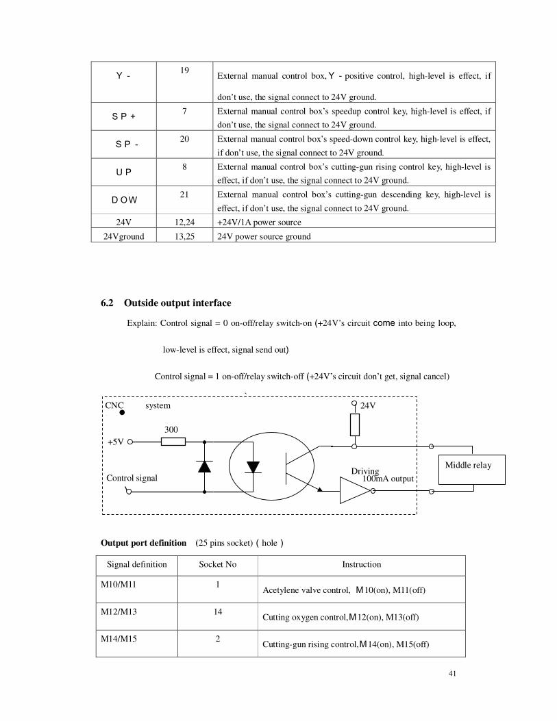
6.2 Outside output interface
Explain: Control signal = 0 on-off/relay switch-on (+24V’s circuit come into being loop,
low-level is effect, signal send out)
Control signal = 1 on-off/relay switch-off (+24V’s circuit don’t get, signal cancel)
`
�
Output port definition (25 pins socket)(hole)
Signal definition Socket No Instruction
M10/M11 1 Acetylene valve control, M10(on), M11(off)
M12/M13 14 Cutting oxygen control,M12(on), M13(off)
M14/M15 2 Cutting-gun rising control,M14(on), M15(off)
300
24V
+5V
Driving 100mA output
Middle relay
CNC system
inside
Control signal
42
M16/M17 15 Cutting-gun descending control,M16(on), M17(off)
M20/M21 3 Ignition control,M20(on), M21(off)
M18/M19 16 Output port 6# control,M18(on), M19(off)
M22/M23 4 Output port 7# control,M22(on), M23(off)
M24/M25 17 Preheat oxygen valve control,M24(on), M25(off)
M40/M41 5 Output port 9# control,M40(on), M41(off)
M26/M27 18 Output port10# control,M26(on), M27(off)
M28/M29 6 Output port 11# control,M28(on), M29(off)
M32/M33 19 Output port 12# control,M32(on), M33(off)
M34/M35 7 Output port 13# control,M34(on), M35(off)
M36/M37 20 Output port 14# control,M36(on), M37(off)
M38/M39 8 Output port 15# control,M38(on), M39(off)
M42/M43 21 Output port 16# control,M42(on), M43(off)
0-10V 9,22
0-10V Voltage output
24V 12,24 +24V / 1A Power source
24V ground 13,25 24V ground
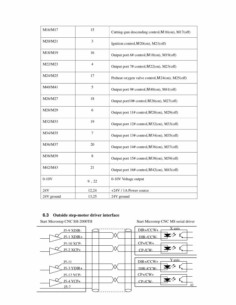
6.3 Outside step-motor driver interface
J5-9 XDIR-
J5-1 XDIR+
J5-10 XCP-
J5-2 XCP+
J5-11
J5-3 YDIR+
J5-12 YCP-
J5-4 YCP+
DIR+/CCW+
DIR-/CCW-
CP+/CW+
CP-/CW-
DIR+/CCW+
DIR-/CCW-
CP+/CW+
CP-/CW-
Start Microstep CNC SH-2000TH
X axis
Y axis
Start Microstep CNC MS serial driver
J5-7
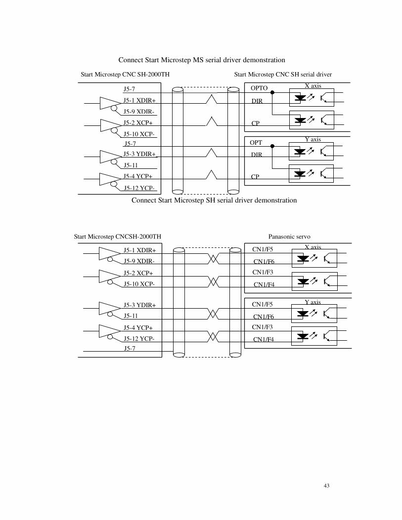
43
J5-1 XDIR+
J5-10 XCP-
J5-2 XCP+
J5-11
J5-3 YDIR+
J5-12 YCP-
J5-4 YCP+
OPTO
DIR
CP
OPT
DIR
CP
Start Microstep CNC SH-2000TH
X axis
Y axis
Start Microstep CNC SH serial driver
J5-7
Connect Start Microstep SH serial driver demonstration
J5-9 XDIR-
J5-7
J5-1 XDIR+
J5-9 XDIR-
J5-2 XCP+
J5-10 XCP-
J5-3 YDIR+
J5-11
J5-4 YCP+
J5-12 YCP-
CN1/F5
CN1/F6
CN1/F3
CN1/F4
CN1/F5
CN1/F6
CN1/F3
CN1/F4
Start Microstep CNCSH-2000TH
X axis
Y axis
Panasonic servo
J5-7
Connect Start Microstep MS serial driver demonstration
44
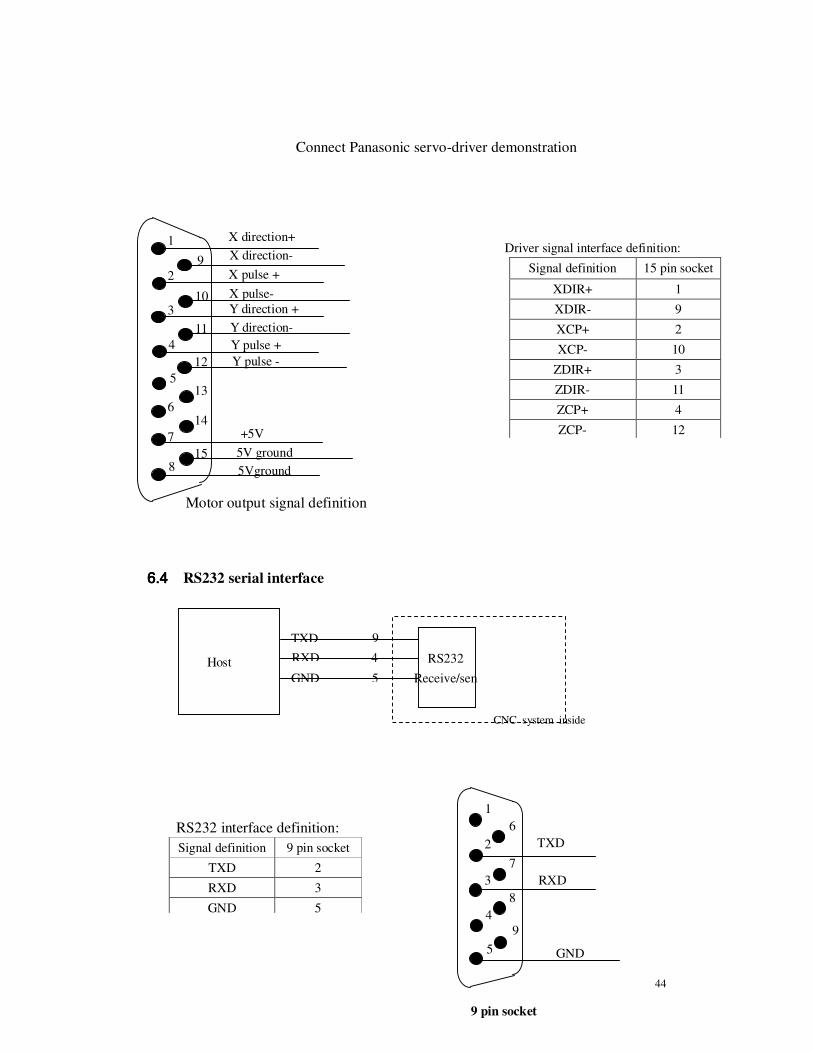
6.4 6.4 6.4 6.4 RS232 serial interface
RS232 interface definition:
Signal definition 9 pin socket
TXD 2
RXD 3
GND 5
Host
computer
TXD
RXD
GND
RS232
Receive/sen
CNC system inside
4
9
5
Connect Panasonic servo-driver demonstration
X direction- 1
6
2
3
4
5
10
11
12
X direction+
+5V
Driver signal interface definition:
Signal definition 15 pin socket
XDIR+ 1
XDIR- 9
XCP+ 2
XCP- 10
ZDIR+ 3
ZDIR- 11
ZCP+ 4
ZCP- 12 7
8
9 X pulse +
X pulse-
Y direction +
Y direction-
Y pulse +
Y pulse -
13
14
15 5V ground
5Vground
Motor output signal definition
1
6
2
3
4
5
7
8
9
GND
RXD
TXD
9 pin socket
45
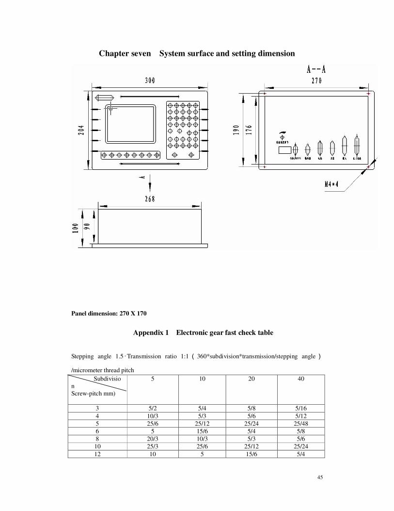
Chapter seven System surface and setting dimension
Panel dimension: 270 X 170
Appendix 1 Electronic gear fast check table
Stepping angle 1.5 · Transmission ratio 1:1 ( 360*subdivision*transmission/stepping angle)
/micrometer thread pitch
Subdivisio
n
Screw-pitch mm)
5 10 20 40
3 5/2 5/4 5/8 5/16
4 10/3 5/3 5/6 5/12
5 25/6 25/12 25/24 25/48
6 5 15/6 5/4 5/8
8 20/3 10/3 5/3 5/6
10 25/3 25/6 25/12 25/24
12 10 5 15/6 5/4

46
Stepping angle0.75· Transmission ratio 1:1(360*subdivision*transmission/stepping angle)
/micrometer thread pitch
Subdivisio
n
Screw-pitch(mm)
5 10 20 40
3 5/4 5/8 5/16 5/32
4 5/3 5/6 5/12 5/24
5 25/12 25/24 25/48 25/96
6 5/2 5/4 5/8 5/16
8 10/3 5/3 5/6 5/12
10 25/6 25/12 25/24 25/48
12 5 5/2 5/4 5/8
Stepping angle 0.6 · Transmission ratio 1:1 ( 360*subdivision*transmission/stepping angle)
/micrometer thread pitch
Subdivisio
n
Screw-pitch (mm)
5 10 20 40
3 1 1/2 1/4 1/8
4 4/3 2/3 1/3 1/6
5 5/3 5/6 5/12 5/24
6 2 1 1/2 1/4
8 8/3 4/3 2/3 1/3
10 10/3 5/3 5/6 5/12
12 4 2 1 1/2
Stepping angle 1.8·Transmission ratio 1:1(360*subdivision*transmission/stepping angle)/micrometer thread pitch
Subdivisio
n
Screw-pitch(mm)
5 10 20 40
3 3 3/2 3/4 3/8
4 4 2 1 1/2
5 5 5/2 5/4 5/8
6 6 3 3/2 3/4
8 8 4 2 1
10 10 5 5/2 5/4
12 12 6 3 3/2

47
Appendix 2 Error information table
Error code Error contents
40H ‘urgent stop’ key press
41H X axis positive margin
42H X axis negative margin
43H Y axis positive margin
44H Y axis negative margin
45H Software coordinates negative margin
46H Software coordinates positive margin
01H When programming, there are unwanted or illegal character
20H Division overflow
21H Arc(G02,G03)Start point or end point have error
22H Arc(G02,G03)radius have error.
24H Arc(G02,G03)term have error.
34H Executing illegal operation
Neri Machine Tools Pvt Ltd.
Plot No. 92/93, 7th
Main, 3rd
Phase, Peenya Industrial Area, Bangalore – 560 058 (India)
Phone: +91 80 28374885, Fax: +91 80 28397834, E-mail: [email protected]
Website: www.nerigroup.in