nerctranslate this page filings and orders...%pdf-1.6 %âãÏÓ 4780 0 obj > endobj xref 4780 26...
TRANSCRIPT

May 5, 2009
VIA ELECTRONIC FILING Claudine Dutil-Berry, Secretary of the Board National Energy Board 444 Seventh Avenue SW Calgary, Alberta T2P 0X8 Re: North American Electric Reliability Corporation Dear Ms. Dutil-Berry:
The North American Electric Reliability Corporation (“NERC”) hereby submits
this petition seeking approval for interpretations of requirements in three NERC
Reliability Standards that are contained in Exhibits A-1 and B-1 to this petition:
− BAL-001-0 — Real Power Balancing Control Performance, Requirement R1
− BAL-003-0 — Frequency Response and Bias, Requirement R3, and
− VAR-002-1 — Generator Operation for Maintaining Network Voltage
Schedules, Requirements R1 and R2.
The formal interpretations have been approved by the NERC Board of Trustees. NERC
requests these interpretations be made effective immediately after approval.
NERC’s petition consists the following: • This transmittal letter; • A table of contents for the entire petition; • A narrative description explaining how the formal interpretations meet the
reliability goal of the standards involved; • Formal interpretations submitted for approval (Exhibits A-1 an B-1);

• Affected Reliability Standards that include the appended interpretations (Exhibits A-2 an B-2); and
• The complete development record of the formal interpretations (Exhibits A-3 and B-3).
Please contact the undersigned if you have any questions. Respectfully submitted,
/s/ Rebecca J. Michael
Rebecca J. Michael
Attorney for North American Electric Reliability Corporation

BEFORE THE NATIONAL ENERGY BOARD
NORTH AMERICAN ELECTRIC ) RELIABILITY CORPORATION )
PETITION OF THE NORTH AMERICAN ELECTRIC RELIABILITY CORPORATION
FOR APPROVAL OF FORMAL INTERPRETATIONS TO RELIABILITY STANDARDS
Rick Sergel President and Chief Executive Officer David N. Cook Vice President and General Counsel North American Electric Reliability Corporation 116-390 Village Boulevard Princeton, NJ 08540-5721 (609) 452-8060 (609) 452-9550 – facsimile [email protected]
Rebecca J. Michael Attorney North American Electric Reliability
Corporation 1120 G Street, N.W. Suite 990 Washington, D.C. 20005-3801 (202) 393-3998 (202) 393-3955 – facsimile [email protected]
May 5, 2009

TABLE OF CONTENTS
I. Introduction...........................................................................................................1
II. Notices and Communications…………………………….……………………..2
III. Background:..........................................................................................................3
a. Reliability Standards Development Procedure .......................................... 4
IV. BAL-001-0 — Real Power Balancing Control Performance, Requirement R1 and BAL-003-0 — Frequency Response and Bias, Requirement R3 ..................5
a. Justification for Approval of Formal Interpretation……………………….6
b. Summary of the Reliability Standard Development Proceedings………..11
V. VAR-002-1 — Generator Operation for Maintaining Network Voltage Schedules, Requirements R1 and R2…………………………………………..18
a. Justification for Approval of Formal Interpretation……………………...19
b. Summary of the Reliability Standard Development Proceedings………..22
VI. Conclusion .........................................................................................................24
Exhibit A-1 – Interpretations of Reliability Standards BAL-001-0, Requirement R1 and BAL-003-0, Requirement R3 Proposed for Approval
Exhibit A-2 – Reliability Standards BAL-001-0a and BAL-003-0a Exhibit A-3 – Record of Development of Formal Interpretations for BAL-001-0,
Requirement R1 and BAL-003-0, Requirement R3 Exhibit B-1 – Interpretation of Reliability Standard VAR-002-1, Requirements R1
and R2 Proposed for Approval
Exhibit B-2 – Reliability Standard VAR-002-1a
Exhibit B-3 – Record of Development of Formal Interpretations for VAR-002-1, Requirements R1 and R2
Page 1
I. INTRODUCTION
The North American Electric Reliability Corporation (“NERC”) hereby requests
approval of interpretations to requirements of three NERC Reliability Standards:
− BAL-001-0 — Real Power Balancing Control Performance, Requirement R1
− BAL-003-0 — Frequency Response and Bias, Requirement R3, and
− VAR-002-1 — Generator Operation for Maintaining Network Voltage
Schedules, Requirements R1 and R2.
This petition is the first request by NERC for approval of these formal
interpretations to requirements of existing NERC Reliability Standards. No
modifications to the language contained in these specific requirements are being
proposed. However, NERC has included for information the approved Reliability
Standards to which the proposed interpretations are appended.
The NERC Board of Trustees approved the formal interpretation to VAR-002-1
— Generator Operation for Maintaining Network Voltage Schedules, Requirements R1
and R2 on August 1, 2007; and, BAL-001-0 — Real Power Balancing Control
Performance, Requirement R1 and BAL-003-0 — Frequency Response and Bias,
Requirement R3 on October 23, 2007. NERC requests approval of these formal
interpretations, to be made effective immediately after approval. Exhibits A-1 and B-1 to
this filing set forth the formal interpretations. Exhibits A-2 and B-2 contain the affected
Reliability Standards containing the appended interpretations. Exhibits A-3 and B-3
contain the complete development records of the formal interpretations to the Reliability
Standard requirements.

Page 2
NERC filed these formal interpretations with the Federal Energy Regulatory
Commission (“FERC”) and is filing them with the other applicable governmental
authorities in Canada.
II. NOTICES AND COMMUNICATIONS
Notices and communications with respect to this filing may be addressed to the
following:
Rick Sergel President and Chief Executive Officer David N. Cook Vice President and General Counsel North American Electric Reliability Corporation 116-390 Village Boulevard Princeton, NJ 08540-5721 (609) 452-8060 (609) 452-9550 – facsimile [email protected]
Rebecca J. Michael Attorney North American Electric Reliability
Corporation 1120 G Street, N.W. Suite 990 Washington, D.C. 20005-3801 (202) 393-3998 (202) 393-3955 – facsimile [email protected]
III. BACKGROUND
a. Reliability Standards Development Procedure
NERC develops reliability standards in accordance with Section 300 (Reliability
Standards Development) of its Rules of Procedure and the NERC Reliability Standards
Development Procedure, which is incorporated into the Rules of Procedure as Appendix
3A. NERC’s proposed rules provide for reasonable notice and opportunity for public
comment, due process, openness, and a balance of interests in developing reliability
standards and thus satisfies certain of the criteria for approving reliability standards.
The development process is open to any person or entity with a legitimate interest
in the reliability of the bulk power system. NERC considers the comments of all

Page 3
stakeholders and a vote of stakeholders and the NERC Board of Trustees is required to
approve a reliability standard for submission to the applicable governmental authorities.
Additionally, all persons who are directly or materially affected by the reliability
of the North American bulk power system are permitted to request an interpretation of the
reliability standard, as discussed in NERC’s Reliability Standards Development
Procedure. When requested, NERC will assemble a team with the relevant expertise to
address the interpretation request and, within 45 days, present a formal interpretation for
industry ballot. If approved by the ballot pool and the NERC Board of Trustees, the
interpretation is appended to the reliability standard and filed for approval by the
applicable governmental authorities to be made effective when approved. When the
affected reliability standard is next revised using the reliability standards development
process, the interpretation will then be incorporated into the reliability standard.
The formal interpretations set out in Exhibits A-1 and B-1have been developed
and approved by industry stakeholders using NERC’s Reliability Standards Development
Procedure, and they have been approved by the NERC Board of Trustees as outlined in
the Introduction section above.
IV. BAL-001-0 — Real Power Balancing Control Performance, Requirement R1 and BAL-003-0 — Frequency Response and Bias, Requirement R3
In Section IV(a), NERC explains the need for and development of the formal
interpretations of BAL-001-0 — Real Power Balancing Control Performance,
Requirement R1 and BAL-003-0 — Frequency Response and Bias, Requirement R3. In
addition, NERC demonstrates that the formal interpretation is consistent with the stated
reliability goal of the Reliability Standards and the requirements thereunder. Set forth
immediately below in Section IV(b) are the stakeholder ballot results and an explanation

Page 4
of how stakeholder comments were considered and addressed by the standard drafting
team assembled to provide the interpretation.
The complete development record for the formal interpretation is set forth in Exhibit
A-3. Exhibit A-3 includes the request for interpretation, the response to the request for
interpretation, the ballot pool and the final ballot results by registered ballot body
members, stakeholder comments received during the balloting and how those comments
were considered.
a. Justification for Approval of Formal Interpretation
The stated purpose of BAL-001-0 — Real Power Balancing Control Performance
(the “control performance standard” or “CPS”) is “to maintain interconnection steady-
state frequency within defined limits by balancing real power demand and supply in real-
time.” Requirement R1 of this Reliability Standard provides the definition of area control
error (“ACE”) and the limits established for control performance standard 1:
Requirement R1. Each Balancing Authority shall operate such that, on a rolling 12-month basis, the average of the clock-minute averages of the Balancing Authority’s Area Control Error (ACE) divided by 10B (B is the clock-minute average of the Balancing Authority Area’s Frequency Bias) times the corresponding clock-minute averages of the Interconnection’s Frequency Error is less than a specific limit. This limit ε12 is a constant derived from a targeted frequency bound (separately calculated for each Interconnection) that is reviewed and set as necessary by the NERC Operating Committee. The stated purpose of BAL-003-0 — Frequency Response and Bias is to “provide
a consistent method for calculating the Frequency Bias component of ACE.”
Requirement R3 of this Reliability Standard addresses the use of tie-line frequency bias
as the normal mode of automatic generation control used by balancing authorities:

Page 5
Requirement R3. Each Balancing Authority shall operate its Automatic Generation Control (AGC) on Tie Line Frequency Bias, unless such operation is adverse to system or Interconnection reliability.
On June 1, 2007, the Western Electricity Coordinating Council (“WECC”)
requested that NERC provide a formal interpretation of Requirements R1 and R3 of the
BAL-001-0 and BAL-003-0 Reliability Standards, respectively. Specifically, WECC
asked if the use of the WECC’s existing Automatic Time Error Correction (“WATEC”)
procedure, which is currently proposed to be a regional reliability standard, violates
Requirement R1 of BAL-001-0 or Requirement R3 of BAL-003-0.
WECC’s proposed regional reliability standard is based on the existing WATEC
procedure1 that makes the WATEC process mandatory for balancing authorities in the
Western Interconnection. (WECC submitted a regional reliability standard regarding
WATEC for NERC review in August 2007 and the proposed regional reliability standard
is being processed for approval through the NERC Reliability Standards Development
Procedure in accordance with NERC’s Rules of Procedure.) During the development of
the proposed regional reliability standard, however, members of WECC expressed some
concern that compliance with the existing WATEC process would result in non-
compliance with certain of the NERC’s Reliability Standards and would thus create a
conflict.
According to WECC, if WECC’s current WATEC approach is determined by
NERC and the applicable governmental authorities to be appropriate, then interim
clarification in the form of a formal interpretation would allow WECC users, owners, and
operators to continue to utilize WATEC as regional criteria until a WECC regional
reliability standard is formally approved by the applicable governmental authorities. The 1 http://www.wecc.biz/documents/library/procedures/Time_Error_Procedure_10-04-02.pdf

Page 6
first question posed by WECC is: “does the use of the [WATEC] procedure violate
Requirement R1 of BAL-001-0?” As explained below, the use of WATEC for control
does not result in a violation of BAL-001-0 Requirement R1, provided that (i) WECC’s
balancing authorities use the raw and unadjusted ACE for control performance reporting
purposes, and (ii) the raw unadjusted ACE complies with Requirement R1.
WECC proposed a second question in its request for interpretation: “does the use
of the [WATEC] procedure violate Requirement R3 of BAL-003-0”? Also, as explained
below, the use of the WATEC procedure does not violate Requirement R3 of BAL-003-
0, provided that (i) a balancing authority uses the tie-line frequency bias mode as the
underlying control mode, and (ii) Control Performance Standard (“CPS1”) (per BAL-
001-0 Requirement R1) is measured and reported on the associated ACE equation.
In order to provide the context for the formal interpretations, it is necessary to
explain the differences in the ACE calculation in the NERC Reliability Standard and the
existing WATEC procedures. NERC’s BAL-001-0 Reliability Standard includes the
following description for ACE:
ACE = (NIA − NIS) − 10B (FA − FS) − IME where • NIA is the algebraic sum of actual flows on all tie-lines. • NIS is the algebraic sum of scheduled flows on all tie-lines. • B is the Frequency Bias Setting (MW/0.1 Hz) for the balancing authority.
The constant factor 10 converts the frequency setting to MW/Hz. • FA is the actual frequency. • FS is the scheduled frequency. FS is normally 60 Hz but may be offset to
effect manual time error corrections. • IME is the meter error correction factor typically estimated from the
difference between the integrated hourly average of the net tie-line flows (NIA) and the hourly net interchange demand measurement (megawatt-hour). This term should normally be very small or zero.

Page 7
WATEC utilizes this basic ACE equation modified with an automatic time error
correction term and with T0b added:
ACE = (NIA − NIS) − 10B (FA − FS) −T0b + IME + {WECC Time Error Correction Term}2
The automatic time error correction component is based on a balancing
authority’s accumulated primary inadvertent interchange. In addition, WECC includes
another inadvertent interchange offset term in the ACE equation, T0b, to bilaterally
correct inadvertent interchange accumulations. In part 1.a.3. of the WECC procedure for
time error control, WECC clearly states that the time error bias term shall not be used in
ACE when determining CPS compliance but shall be used for control only. Likewise, the
WECC description of the ACE calculation3 also states that this term is not to be included
for NERC performance reporting. This direction is important relative to the formal
interpretation.
Pursuant to the Reliability Standards Development Procedure, NERC selected the
Resources Subcommittee of the NERC Operating Committee as its subject matter expert
to consider the two questions and develop the interpretation responses.
Does the use of the WATEC procedure violate Requirement R1 of BAL-001-0? The use of WATEC does not violate Requirement R1 of BAL-001-0. Control
performance is measured using the ACE equation and is determined to be satisfactory if a
balancing authority remains within established limits as defined in Requirement R1. The
WATEC procedure requires balancing authorities to maintain a raw ACE that is not
layered with other control objectives (such as automatic time error correction or manual
2 For the purposes of this discussion, the WECC time error correction term does not need to be detailed. 3 http://www.wecc.biz/documents/library/procedures/ACE_Description_Final_4-21-06.pdf

Page 8
inadvertent interchange payback) for control performance reporting to NERC. WECC’s
balancing authorities control their balancing authority areas using the WATEC-adjusted
ACE.
The use of WATEC for control does not result in a violation of BAL-001-0
Requirement R1, provided that (i) WECC’s balancing authorities use the raw and
unadjusted ACE for control performance reporting purposes and (ii) provided the raw
unadjusted ACE complies with Requirement R1. However, compliance with the
WATEC procedure does not necessarily result in compliance with NERC CPS1 as
required by Requirement R1. By using the raw, unadjusted ACE values, NERC is able to
measure WECC’s balancing authorities’ performance on a consistent basis with other
balancing authorities across North America. In this regard, the formal interpretation
supports the objective for BAL-001-0: to maintain interconnection steady-state
frequency within defined limits by balancing real power demand and supply in real-time.
Does the use of the WATEC procedure violate Requirement R3 of BAL-003-0? The use of the WATEC procedure does not violate Requirement R3 of BAL-003-
0. Requirement R3 requires each balancing authority to operate its AGC in the tie-line
frequency bias mode. Tie-line frequency bias is one of the three foundational control
modes available in a balancing authority’s energy management system. The other two
are flat-tie and flat-frequency modes.
Many balancing authorities layer other control objectives on their basic control
mode, such as automatic inadvertent payback, control performance standard optimization,
time control (in single balancing area interconnections), for example. Provided that a
balancing authority uses the tie-line frequency bias mode as the underlying control mode

Page 9
and CPS1 (per BAL-001-0 Requirement R1) is measured and reported on the associated
ACE equation, there is no violation of BAL-003-0 Requirement R3. This formal
interpretation of R3 of BAL-003-0 reinforces the expectation that tie-line frequency
control is the preferred control mode for balancing authorities in North America and
thereby supports the purpose of the Reliability Standard: to provide a consistent method
for calculating the frequency bias component of the ACE equation.
b. Summary of the Reliability Standard Development Proceedings On June 1, 2007, WECC requested that NERC provide formal interpretations of
Requirements R1 and R3 of the BAL-001-0 and BAL-003-0 Reliability Standards,
respectively. In accordance with its Reliability Standard Development Procedure, NERC
posted its response to the request for interpretation for a 30-day pre-ballot period that
took place from July 9, 2007 – August 7, 2007. NERC conducted an initial ballot from
August 7, 2007 – August 16, 2007, but a negative vote was received with associated
comments. This triggered the need to conduct a recirculation ballot after the
interpretation team responded to the comments. Accordingly, a recirculation ballot was
conducted from August 23, 2007 – September 1, 2007. The formal interpretations were
approved by the ballot pool with a weighted segment average of 97.2 %, with 96.3 % of
the ballot pool voting.
Four sets of comments were received during the ballot process, with only one tied
to a negative ballot. Supporting comments from Duke Energy and the California Energy
Commission highlighted how the distinctions in the interpretation do not adversely
impact any party in other interconnections and allows the interconnections that want to
use automatic time error correction the ability to do so. This procedure requires that raw

Page 10
ACE used for reporting of CPS compliance per the BAL-001-0 Reliability Standard and
disturbance control standard performance per BAL-002-0 does not include the WATEC
modified time error correction term. Duke Energy suggested that balancing authorities in
WECC should provide certain assurances to WECC that the raw ACE is being calculated
in accordance with the NERC Reliability Standard BAL-001-0 for compliance purposes.
NERC agrees with this comment but offers that the validation of such important
information should occur in the domain of normal compliance audits, not in standards
development.
NERC did receive one comment associated with a negative vote. Xcel Energy
stated that the interpretation appears to creates a disconnect between the way one Region
implements the ACE calculation compared to the NERC ACE, under which all
compliance will be determined. NERC responded that many balancing authorities are
permitted to, and employ, a modified control ACE for a variety of reasons. As set forth
above, provided the balancing authorities calculate and report their performance using
raw ACE, their conformance to the requirements is measured in a comparable manner,
which is the overall goal.
Energy Mark, Inc. abstained during the vote but commented that the proposed
WECC procedure does not have a compliance measure established today. The purpose of
this interpretation is not to discuss the merits of the proposed WECC procedure nor the
compliance expectations for it. Generally, from a procedural standpoint, an interpretation
of a NERC Reliability Standard is not the mechanism to add or modify elements of the
Reliability Standard.
Page 11
V. VAR-002-1 — Generator Operation for Maintaining Network Voltage Schedules, Requirements R1 and R2
In Section VI(a), NERC explains the need for and development of the formal
interpretations of VAR-002-1 — Generator Operation for Maintaining Network Voltage
Schedules, Requirements R1 and R2. In addition, NERC demonstrates that the formal
interpretations are consistent with the stated reliability goal of the Reliability Standard
and the requirements thereunder. Set forth immediately below in Section VI(b) are the
stakeholder ballot results and how stakeholder comments were considered and addressed
by the team assembled to provide the interpretations.
The complete development record for the formal interpretations is set forth in
Exhibit C-3. Exhibit C-3 includes the request for interpretations, the response to the
request for interpretations, the ballot pool and the final ballot results by registered ballot
body members, stakeholder comments received during the balloting and how those
comments were considered.
a. Justification for Approval of Formal Interpretation
The stated purpose of VAR-002-1 — Generator Operation for Maintaining
Network Voltage Schedules is to ensure generators provide reactive and voltage control
necessary to ensure voltage levels, reactive flows, and reactive resources are maintained
within applicable facility ratings to protect equipment and the reliable operation of the
interconnection. Requirements R1 and R2 of this standard state:
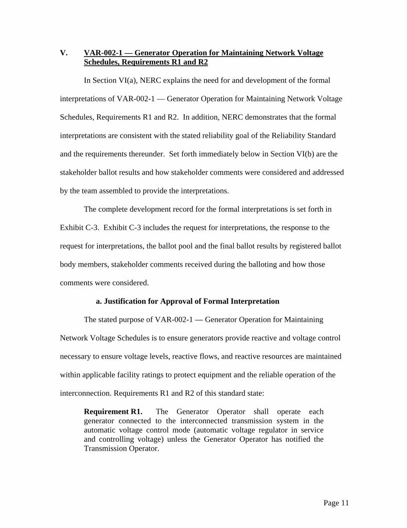
Requirement R1. The Generator Operator shall operate each generator connected to the interconnected transmission system in the automatic voltage control mode (automatic voltage regulator in service and controlling voltage) unless the Generator Operator has notified the Transmission Operator.

Page 12
Requirement R2. Unless exempted by the Transmission Operator, each Generator Operator shall maintain the generator voltage or Reactive Power output (within applicable Facility Ratings4) as directed by the Transmission Operator. On January 24, 2007, NERC received a request to provide a formal interpretation
of Requirements R1 and R2. Specifically, the requester asked the following questions:
“First, does AVR (automatic voltage regulator) operation in the constant PF (power factor) or constant Mvar modes comply with [Requirement] R1?” “Second, does Requirement R2 give the Transmission Operator the option of directing the Generation Owner to operate the AVR in the constant pf or constant Mvar modes rather than the constant voltage mode? In accordance with its Reliability Standards Development Procedure, NERC
selected the Phase III/IV Planning Standards Drafting Team as its subject matter expert to
consider the questions and develop the formal interpretations. This standard drafting
team originally drafted the VAR-002-1 Reliability Standard that was approved by the
NERC Board of Trustees in 2006. On March 5, 2007, the team provided its
interpretations as requested by NERC.
In response to the first question, “does AVR operation in the constant PF or
constant Mvar modes comply with Requirement R1?” the following interpretation was
provided:
“No, only operation in constant voltage mode meets this requirement. This answer is predicated on the assumption that the generator has the physical equipment that will allow such operation and that the Transmission Operator has not directed the generator to run in a mode other than constant voltage.”
4 When a Generator is operating in manual control, reactive power capability may change based on stability considerations and this will lead to a change in the associated Facility Ratings.

Page 13
In response to the second question, “does [Requirement] R2 give the
Transmission Operator the option of directing the Generation Owner to operate the AVR
in the constant PF or constant Mvar modes rather than the constant voltage mode?” the
following interpretation was provided:
“Yes, if the Transmission Operator specifically directs a Generator Operator to operate the AVR in a mode other than constant voltage mode, then that directed mode of AVR operation is allowed.”
The team also supported its interpretation by including the following discussion in
its formal response:
“Requirement R1 of Standard VAR-002-1 states that Generation Operators shall operate each generator connected to the interconnected transmission system in the automatic voltage control mode (automatic voltage regulator in service and controlling voltage) unless the Generator Operator has notified the Transmission Operator. Requirement R1 clearly states controlling voltage. This can only be accomplished by using the automatic voltage control mode. Using the Power Factor (PF) or constant Mvar control is not a true method to control voltage even though they may have some effect on voltage. This is the baseline mode of operation that is clearly conditioned by “unless the Generator Operator has notified the Transmission Operator.” The following Requirement R2 introduces the possibility of an exemption to this baseline mode of operation discussed below. The above interpretation is further reinforced by reviewing the origin of the requirement. The current Requirement R1 is an evolution of the words in the associated source document, namely NERC Planning Standards Compliance Template for III.C.M1, “Operation of all synchronous generators in the automatic voltage control mode.” As stated in the original III.C.S1 Standard5:
“All synchronous generators connected to the interconnected transmission systems shall be operated with their excitation system
5 The NERC Planning Standards and NERC Operating Policies were the precursor to the comprehensive set of reliability standards that were approved by the NERC Board of Trustees in April 2005, known as Version 0. Until the Version 0 standards were approved, these operating policies and planning standards served as the core reliability guidance in the voluntary era of compliance that pre-dated the Energy Policy Act of 2005.

Page 14
in the automatic voltage control mode (automatic voltage regulator in service and controlling voltage) unless approved otherwise by the transmission system operator.”
Requirement R2 of Standard VAR-002-1 goes on to state that “Unless exempted by the Transmission Operator, each Generator Operator shall maintain the generator voltage or Reactive Power output (within applicable Facility Ratings) as directed by the Transmission Operator.” The purpose of this requirement is to give the Transmission Operator the ability to direct the Generator Operator to use another mode of operation. This ability may be necessary based on the Transmission Operator’s system studies and/or knowledge of system conditions. This ability also gives the Transmission Operator the latitude to work with the Generator Operator who has a generating unit that lacks the physical equipment to be able to run in the automatic voltage control mode or has contractual requirements to operate in a certain manner. Both Requirements R1 and R2 in VAR-002-1 were worded such that they
coordinate with Requirement R4 in VAR-001-1:
“Each Transmission Operator shall specify a voltage or Reactive Power schedule at the interconnection between the generator facility and the Transmission Owner's facilities to be maintained by each generator. The Transmission Operator shall provide the voltage or Reactive Power schedule to the associated Generator Operator and direct the Generator Operator to comply with the schedule in automatic voltage control mode (AVR in service and controlling voltage).”
Again this Requirement R4 reflects that the baseline mode of operation is to use the automatic voltage control mode with the option for the Transmission Operator to specify other modes of operation as dictated by system studies and needs to maintain system reliability.” NERC believes the formal interpretation and supporting discussion clearly state
that the voltage control mode is the preferred method of operating the AVR unless the
generator operator is expressly exempted by the transmission operator from operating in
this mode. Further, the interpretation reinforces that the transmission operator is
responsible to ensure voltage levels, reactive flows, and reactive resources are maintained
within applicable facility ratings to protect equipment and the reliable operation of the

Page 15
interconnection, which includes the provision of voltage and reactive support from
generators. Thus, these interpretations directly support the intent of the requirements and
the goal of the VAR-002-1 standard.
b. Summary of the Reliability Standard Development Proceedings On January 24, 2007, NERC received a request for formal interpretation of
Requirements R1 and R2 of the VAR-002-1 Reliability Standard. NERC selected
members of the Phase III/IV standard drafting team that authored the Reliability Standard
to prepare the interpretation. On March 5, 2007, the team provided the formal
interpretations discussed in the previous section.
NERC published the formal interpretations for a 30-day pre-ballot review that
started on March 15, 2007. The initial ballot was conducted from April 17, 2007 – April
26, 2007 and achieved a quorum and sufficient affirmative ballots for passage, but there
were four negative ballots cast with comments, necessitating a recirculation ballot.
- Three balloters from the same corporate family (Baltimore Gas and Electric, Constellation Energy, and Constellation Generation Group) suggested that the interpretation was not acceptable because they have equipment that could not meet the requirement to have generators in automatic voltage control mode to control voltage. The drafting team did not modify the interpretation in response to these comments because the standard does allow the transmission operator to exempt generators from compliance with the requirement.
- Tennessee Valley Authority indicated that the interpretation could be misleading when one considers the response to the first question is ‘no, unless exempted by the transmission operator.’ The drafting team did not modify the interpretation in response to this comment because the interpretation was not intended to re-write or improve the wording of the requirements. The interpretation must be considered in the context of all requirements in the standard, not with respect to individual requirements in isolation.

Page 16
NERC conducted the recirculation ballot from June 20, 2007 – June 29, 2007 and
the ballot results were released on July 3, 2007. The interpretations passed with a
quorum of 85.5 % and a weighted segment approval of 98.7 %.
VII. CONCLUSION
NERC requests approval of the formal interpretations to the following
requirements in the NERC Reliability Standards:
− BAL-001-0 — Real Power Balancing Control Performance, Requirement R1
− BAL-003-0 — Frequency Response and Bias, Requirement R3, and
− VAR-002-1 — Generator Operation for Maintaining Network Voltage Schedules, Requirements R1 and R2.
as set out in Exhibits A-1, B-1, and C-1. NERC requests that these interpretations be
made effective immediately upon issuance of the order in this proceeding.
Respectfully submitted,
Rick Sergel President and Chief Executive Officer David N. Cook Vice President and General Counsel North American Electric Reliability Corporation 116-390 Village Boulevard Princeton, NJ 08540-5721 (609) 452-8060 (609) 452-9550 – facsimile [email protected]
/s/ Rebecca J. Michael Rebecca J. Michael Attorney North American Electric Reliability
Corporation 1120 G Street, N.W. Suite 990 Washington, D.C. 20005-3801 (202) 393-3998 (202) 393-3955 – facsimile [email protected]

Exhibit A-1
Interpretations of Reliability Standards BAL-001-0, Requirement R1 and BAL-003-0,
Requirement R3 Proposed for Approval

Page 1 of 1 October 23, 2007
Approved by Stakeholders: September 1, 2007 Approved by NERC Board of Trustees: October 23, 2007
Interpretation of BAL-001-0 — Real Power Balancing Control Performance, Requirement 1 and BAL-003-0 — Frequency Response and Bias, Requirement 3
Request for Interpretation received from WECC on June 1, 2007: Does the WECC Automatic Time Error Control Procedure (WATEC) violate Requirement 1 of BAL-001-0 or Requirement 3 of BAL-003-0?
Interpretation provided by NERC Resources Subcommittee on July 6, 2007: Requirement 1 of BAL-001 — Real Power Balancing Control Performance, is the definition of the area control error (ACE) equation and the limits established for Control Performance Standard 1 (CPS1).
The WATEC procedural documents ask Balancing Authorities to maintain raw ACE for CPS
reporting and to control via WATEC-adjusted ACE.
As long as Balancing Authorities use raw (unadjusted for WATEC) ACE for CPS reporting purposes, the use of WATEC for control is not in violation of BAL-001 Requirement 1.
Requirement 3 of BAL-003-0 — Frequency Response and Bias deals with Balancing Authorities using Tie-Line Frequency Bias as the normal mode of automatic generation control.
Tie-Line Frequency Bias is one of the three foundational control modes available in a Balancing
Authority’s energy management system. (The other two are flat-tie and flat-frequency.) Many Balancing Authorities layer other control objectives on top of their basic control mode, such as automatic inadvertent payback, CPS optimization, time control (in single BA Interconnections).
As long as Tie-Line Frequency Bias is the underlying control mode and CPS1 is measured and reported on the associated ACE equation, there is no violation of BAL-003-0 Requirement 3:
ACE = (NIA− NIS) – 10B (FA − FS) − IME
BAL-001-0 R1. Each Balancing Authority shall operate such that, on a rolling 12-month basis, the average of the clock-minute averages of the Balancing Authority’s Area Control Error (ACE) divided by 10B (B is the clock-minute average of the Balancing Authority Area’s Frequency Bias) times the corresponding clock-minute averages of the Interconnection’s Frequency Error is less than a specific limit. This limit ε12 is a constant derived from a targeted frequency bound (separately calculated for each Interconnection) that is reviewed and set as necessary by the NERC Operating Committee.
BAL-003-0 R3. Each Balancing Authority shall operate its Automatic Generation Control (AGC) on Tie Line Frequency Bias, unless such operation is adverse to system or Interconnection reliability.

Exhibit A-2
Reliability Standards BAL-001-0a and BAL-003-0a

Standard BAL-001-0a — Real Power Balancing Control Performance
A. Introduction 1. Title: Real Power Balancing Control Performance
2. Number: BAL-001-0
3. Purpose: To maintain Interconnection steady-state frequency within defined limits by balancing real power demand and supply in real-time.
4. Applicability:
4.1. Balancing Authorities
5. Effective Date: Immediately after approval of applicable regulatory authorities
B. Requirements R1. Each Balancing Authority shall operate such that, on a rolling 12-month basis, the average of
the clock-minute averages of the Balancing Authority’s Area Control Error (ACE) divided by 10B (B is the clock-minute average of the Balancing Authority Area’s Frequency Bias) times the corresponding clock-minute averages of the Interconnection’s Frequency Error is less than a specific limit. This limit ε 2
1 is a constant derived from a targeted frequency bound (separately calculated for each Interconnection) that is reviewed and set as necessary by the NERC Operating Committee.
1
*10
*10 2
1
112
111
≤∈
⎥⎥⎦
⎤
⎢⎢⎣
⎡Δ⎟⎟
⎠
⎞⎜⎜⎝
⎛−
≤∈⎥⎥⎦
⎤
⎢⎢⎣
⎡Δ⎟⎟
⎠
⎞⎜⎜⎝
⎛−
FB
ACEAVG
orFB
ACEAVG i
iPeriod
i
iPeriod
The equation for ACE is:
Adopted by NERC Board of Trustees: October 23, 2007 1 of 7
ACE = (NIA − NIS) − 10B (FA − FS) − IME
where:
• NIA is the algebraic sum of actual flows on all tie lines.
• NIS is the algebraic sum of scheduled flows on all tie lines.
• B is the Frequency Bias Setting (MW/0.1 Hz) for the Balancing Authority. The constant factor 10 converts the frequency setting to MW/Hz.
• FA is the actual frequency.
• FS is the scheduled frequency. FS is normally 60 Hz but may be offset to effect manual time error corrections.
• IME is the meter error correction factor typically estimated from the difference between the integrated hourly average of the net tie line flows (NIA) and the hourly net interchange demand measurement (megawatt-hour). This term should normally be very small or zero.
R2. Each Balancing Authority shall operate such that its average ACE for at least 90% of clock-ten-minute periods (6 non-overlapping periods per hour) during a calendar month is within a specific limit, referred to as L10.
10minute10 )( LACEAVG i ≤−

Standard BAL-001-0a — Real Power Balancing Control Performance
where:
L )10)(10(65.1 10 si BB −−∈
Adopted by NERC Board of Trustees: October 23, 2007 2 of 7
10=
ε10 is a constant derived from the targeted frequency bound. It is the targeted root-mean-square (RMS) value of ten-minute average Frequency Error based on frequency performance over a given year. The bound, ε10, is the same for every Balancing Authority Area within an Interconnection, and Bs is the sum of the Frequency Bias Settings of the Balancing Authority Areas in the respective Interconnection. For Balancing Authority Areas with variable bias, this is equal to the sum of the minimum Frequency Bias Settings.
R3. Each Balancing Authority providing Overlap Regulation Service shall evaluate Requirement M1 (i.e., Control Performance Standard 1 or CPS1) and Requirement M2 (i.e., Control Performance Standard 2 or CPS2) using the characteristics of the combined ACE and combined Frequency Bias Settings.
R4. Any Balancing Authority receiving Overlap Regulation Service shall not have its control performance evaluated (i.e. from a control performance perspective, the Balancing Authority has shifted all control requirements to the Balancing Authority providing Overlap Regulation Service).
C. Measures M1. Each Balancing Authority shall achieve, as a minimum, Requirement 1 (CPS1) compliance of
100%.
CPS1 is calculated by converting a compliance ratio to a compliance percentage as follows:
CPS1 = (2 - CF) * 100%
The frequency-related compliance factor, CF, is a ratio of all one-minute compliance parameters accumulated over 12 months divided by the target frequency bound:
21 )(
month12
∈= −
CFCF
where: ε is defined in Requirement R1. 1
The rating index CF12-month is derived from 12 months of data. The basic unit of data comes from one-minute averages of ACE, Frequency Error and Frequency Bias Settings.
A clock-minute average is the average of the reporting Balancing Authority’s valid measured variable (i.e., for ACE and for Frequency Error) for each sampling cycle during a given clock-minute.
10B-10minute-clockin cycles sampling
minute-clockin cycles sampling
minute-clock
⎟⎟⎠
⎞⎜⎜⎝
⎛
=⎟⎠⎞
⎜⎝⎛
−
∑nACE
BACE
minute-clockin cycles sampling
minute-clockin cycles samplingminute-clock n
FF ∑ Δ
=Δ
The Balancing Authority’s clock-minute compliance factor (CF) becomes:

Standard BAL-001-0a — Real Power Balancing Control Performance
⎥⎦
⎤⎢⎣
⎡Δ⎟
⎠⎞
⎜⎝⎛
−= minute-clock
minute-clockminute-clock *
10F
BACECF
Normally, sixty (60) clock-minute averages of the reporting Balancing Authority’s ACE and of the respective Interconnection’s Frequency Error will be used to compute the respective hourly average compliance parameter.
hourin samples minute-clock
minute-clockhour-clock n
CFCF ∑=
The reporting Balancing Authority shall be able to recalculate and store each of the respective clock-hour averages (CF clock-hour average-month) as well as the respective number of samples for each of the twenty-four (24) hours (one for each clock-hour, i.e., hour-ending (HE) 0100, HE 0200, ..., HE 2400).
∑∑
=
monthin -dayshour-clockin samples minute-one
month-in-dayshour-clockin samples minute-onehour-clock
month-averagehour -clock ][
)])([(CFCF
n
n
∑∑
=
dayin -hoursaverageshour -clockin samples minute-one
day-in-hoursaverageshour -clockin samples minute-onemonth-averagehour -clock
month ][
)])([(CFCF
n
n
The 12-month compliance factor becomes:
( )
∑
∑
=
=−
= 12
1ii-month)in samples minute-one(
12
1iimonthin samples minute-onei-month
month-12
][
)])((CF
n
nCF
In order to ensure that the average ACE and Frequency Deviation calculated for any one-minute interval is representative of that one-minute interval, it is necessary that at least 50% of both ACE and Frequency Deviation samples during that one-minute interval be present. Should a sustained interruption in the recording of ACE or Frequency Deviation due to loss of telemetering or computer unavailability result in a one-minute interval not containing at least 50% of samples of both ACE and Frequency Deviation, that one-minute interval shall be excluded from the calculation of CPS1.
M2. Each Balancing Authority shall achieve, as a minimum, Requirement R2 (CPS2) compliance of 90%. CPS2 relates to a bound on the ten-minute average of ACE. A compliance percentage is calculated as follows:
( ) 100*Periods eUnavailablPeriods Total
Violations12
monthmonth
month⎥⎦
⎤⎢⎣
⎡−
−=CPS
The violations per month are a count of the number of periods that ACE clock-ten-minutes exceeded L10. ACE clock-ten-minutes is the sum of valid ACE samples within a clock-ten-minute period divided by the number of valid samples.
Adopted by NERC Board of Trustees: October 23, 2007 3 of 7

Standard BAL-001-0a — Real Power Balancing Control Performance
Violation clock-ten-minutes
= 0 if
10minutes-10in samples
Ln
ACE≤∑
= 1 if
10minutes-10in samples
Ln
ACE>∑
Each Balancing Authority shall report the total number of violations and unavailable periods for the month. L10 is defined in Requirement R2.
Since CPS2 requires that ACE be averaged over a discrete time period, the same factors that limit total periods per month will limit violations per month. The calculation of total periods per month and violations per month, therefore, must be discussed jointly.
A condition may arise which may impact the normal calculation of total periods per month and violations per month. This condition is a sustained interruption in the recording of ACE.
In order to ensure that the average ACE calculated for any ten-minute interval is representative of that ten-minute interval, it is necessary that at least half the ACE data samples are present for that interval. Should half or more of the ACE data be unavailable due to loss of telemetering or computer unavailability, that ten-minute interval shall be omitted from the calculation of CPS2.
D. Compliance 1. Compliance Monitoring Process
1.1. Compliance Monitoring Responsibility
Regional Reliability Organization.
1.2. Compliance Monitoring Period and Reset Timeframe
One calendar month.
1.3. Data Retention
The data that supports the calculation of CPS1 and CPS2 (Appendix 1-BAL-001-0) are to be retained in electronic form for at least a one-year period. If the CPS1 and CPS2 data for a Balancing Authority Area are undergoing a review to address a question that has been raised regarding the data, the data are to be saved beyond the normal retention period until the question is formally resolved. Each Balancing Authority shall retain for a rolling 12-month period the values of: one-minute average ACE (ACEi), one-minute average Frequency Error, and, if using variable bias, one-minute average Frequency Bias.
1.4. Additional Compliance Information
None.
2. Levels of Non-Compliance – CPS1
2.1. Level 1: The Balancing Authority Area’s value of CPS1 is less than 100% but greater than or equal to 95%.
2.2. Level 2: The Balancing Authority Area’s value of CPS1 is less than 95% but greater than or equal to 90%.
Adopted by NERC Board of Trustees: October 23, 2007 4 of 7

Standard BAL-001-0a — Real Power Balancing Control Performance
Adopted by NERC Board of Trustees: October 23, 2007 5 of 7
2.3. Level 3: The Balancing Authority Area’s value of CPS1 is less than 90% but greater than or equal to 85%.
2.4. Level 4: The Balancing Authority Area’s value of CPS1 is less than 85%.
3. Levels of Non-Compliance – CPS2
3.1. Level 1: The Balancing Authority Area’s value of CPS2 is less than 90% but greater than or equal to 85%.
3.2. Level 2: The Balancing Authority Area’s value of CPS2 is less than 85% but greater than or equal to 80%.
3.3. Level 3: The Balancing Authority Area’s value of CPS2 is less than 80% but greater than or equal to 75%.
3.4. Level 4: The Balancing Authority Area’s value of CPS2 is less than 75%.
E. Regional Differences
1. The ERCOT Control Performance Standard 2 Waiver approved November 21, 2002.
F. Associated Documents 2. Appendix 2 – Interpretation of Requirement R1 approved October 23, 2007.
Version History
Version Date Action Change Tracking 0 February 8, 2005 BOT Approval New
0 April 1, 2005 Effective Implementation Date New
0 August 8, 2005 Removed “Proposed” from Effective Date
Errata
0 July 24, 2007 Corrected R3 to reference M1 and M2 instead of R1 and R2.
Errata
0a December 19, 2007 Added Appendix 2 – Interpretation of R1 approved by BOT on October 23, 2007

Standard BAL-001-0a — Real Power Balancing Control Performance
Adopted by NERC Board of Trustees: October 23, 2007 6 of 7
Appendix 1-BAL-001-0 CPS1 and CPS2 Data
CPS1 DATA Description Retention Requirements
ε1 A constant derived from the targeted frequency bound. This number is the same for each Balancing Authority Area in the Interconnection.
Retain the value of ε1 used in CPS1 calculation.
ACEi The clock-minute average of ACE. Retain the 1-minute average values of ACE (525,600 values).
BBi The Frequency Bias of the Balancing Authority Area.
Retain the value(s) of Bi used in the CPS1 calculation.
FA The actual measured frequency. Retain the 1-minute average frequency values (525,600 values).
FS Scheduled frequency for the Interconnection. Retain the 1-minute average frequency values (525,600 values).
CPS2 DATA Description Retention Requirements
V Number of incidents per hour in which the absolute value of ACE clock-ten-minutes is greater than L10.
Retain the values of V used in CPS2 calculation.
ε10 A constant derived from the frequency bound. It is the same for each Balancing Authority Area within an Interconnection.
Retain the value of ε10 used in CPS2 calculation.
BBi The Frequency Bias of the Balancing Authority Area.
Retain the value of Bi used in the CPS2 calculation.
BBs The sum of Frequency Bias of the Balancing Authority Areas in the respective Interconnection. For systems with variable bias, this is equal to the sum of the minimum Frequency Bias Setting.
Retain the value of Bs used in the CPS2 calculation. Retain the 1-minute minimum bias value (525,600 values).
U Number of unavailable ten-minute periods per hour used in calculating CPS2.
Retain the number of 10-minute unavailable periods used in calculating CPS2 for the reporting period.
Standard BAL-001-0a — Real Power Balancing Control Performance
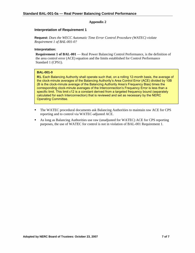
Appendix 2
Interpretation of Requirement 1
Request: Does the WECC Automatic Time Error Control Procedure (WATEC) violate Requirement 1 of BAL-001-0?
Interpretation: Requirement 1 of BAL-001 — Real Power Balancing Control Performance, is the definition of the area control error (ACE) equation and the limits established for Control Performance Standard 1 (CPS1).
Adopted by NERC Board of Trustees: October 23, 2007 7 of 7
BAL-001-0 R1. Each Balancing Authority shall operate such that, on a rolling 12-month basis, the average of the clock-minute averages of the Balancing Authority’s Area Control Error (ACE) divided by 10B (B is the clock-minute average of the Balancing Authority Area’s Frequency Bias) times the corresponding clock-minute averages of the Interconnection’s Frequency Error is less than a specific limit. This limit ε12 is a constant derived from a targeted frequency bound (separately calculated for each Interconnection) that is reviewed and set as necessary by the NERC Operating Committee.
The WATEC procedural documents ask Balancing Authorities to maintain raw ACE for CPS reporting and to control via WATEC-adjusted ACE.
As long as Balancing Authorities use raw (unadjusted for WATEC) ACE for CPS reporting purposes, the use of WATEC for control is not in violation of BAL-001 Requirement 1.

Standard BAL-001-0a — Real Power Balancing Control Performance
Adopted by NERC Board of Trustees: October 23, 2007 1 of 7
A. Introduction 1. Title: Real Power Balancing Control Performance
2. Number: BAL-001-0
3. Purpose: To maintain Interconnection steady-state frequency within defined limits by balancing real power demand and supply in real-time.
4. Applicability:
4.1. Balancing Authorities
5. Effective Date: Immediately after approval of applicable regulatory authorities
B. Requirements R1. Each Balancing Authority shall operate such that, on a rolling 12-month basis, the average of
the clock-minute averages of the Balancing Authority’s Area Control Error (ACE) divided by 10B (B is the clock-minute average of the Balancing Authority Area’s Frequency Bias) times the corresponding clock-minute averages of the Interconnection’s Frequency Error is less than a specific limit. This limit ε1
2 is a constant derived from a targeted frequency bound (separately calculated for each Interconnection) that is reviewed and set as necessary by the NERC Operating Committee.
The equation for ACE is:
ACE = (NIA − NIS) − 10B (FA − FS) − IME
where:
• NIA is the algebraic sum of actual flows on all tie lines.
• NIS is the algebraic sum of scheduled flows on all tie lines.
• B is the Frequency Bias Setting (MW/0.1 Hz) for the Balancing Authority. The constant factor 10 converts the frequency setting to MW/Hz.
• FA is the actual frequency.
• FS is the scheduled frequency. FS is normally 60 Hz but may be offset to effect manual time error corrections.
• IME is the meter error correction factor typically estimated from the difference between the integrated hourly average of the net tie line flows (NIA) and the hourly net interchange demand measurement (megawatt-hour). This term should normally be very small or zero.
R2. Each Balancing Authority shall operate such that its average ACE for at least 90% of clock-ten-minute periods (6 non-overlapping periods per hour) during a calendar month is within a specific limit, referred to as L10.
10minute10 )( LACEAVG i ≤−
1
*10
*10 2
1
112
111
≤∈
⎥⎥⎦
⎤
⎢⎢⎣
⎡Δ⎟⎟
⎠
⎞⎜⎜⎝
⎛−
≤∈⎥⎥⎦
⎤
⎢⎢⎣
⎡Δ⎟⎟
⎠
⎞⎜⎜⎝
⎛−
FB
ACEAVG
orFB
ACEAVG i
iPeriod
i
iPeriod
Formatted: Outline numbered +Level: 2 + Numbering Style: 1, 2, 3,… + Start at: 1 + Alignment: Left +Aligned at: 46.8 pt + Tab after: 72pt + Indent at: 72 pt
Formatted: Indent: Left: 67.7 pt,Bulleted + Level: 1 + Aligned at: 67.5 pt + Tab after: 85.5 pt +Indent at: 85.5 pt
Deleted: April 1, 2005
Deleted: February 8, 2005
Deleted: Effective Date: April 1, 2005

Standard BAL-001-0a — Real Power Balancing Control Performance
Adopted by NERC Board of Trustees: October 23, 2007 2 of 7
where:
L10= )10)(10(65.1 10 si BB −−∈
ε10 is a constant derived from the targeted frequency bound. It is the targeted root-mean-square (RMS) value of ten-minute average Frequency Error based on frequency performance over a given year. The bound, ε10, is the same for every Balancing Authority Area within an Interconnection, and Bs is the sum of the Frequency Bias Settings of the Balancing Authority Areas in the respective Interconnection. For Balancing Authority Areas with variable bias, this is equal to the sum of the minimum Frequency Bias Settings.
R3. Each Balancing Authority providing Overlap Regulation Service shall evaluate Requirement M1 (i.e., Control Performance Standard 1 or CPS1) and Requirement M2 (i.e., Control Performance Standard 2 or CPS2) using the characteristics of the combined ACE and combined Frequency Bias Settings.
R4. Any Balancing Authority receiving Overlap Regulation Service shall not have its control performance evaluated (i.e. from a control performance perspective, the Balancing Authority has shifted all control requirements to the Balancing Authority providing Overlap Regulation Service).
C. Measures M1. Each Balancing Authority shall achieve, as a minimum, Requirement 1 (CPS1) compliance of
100%.
CPS1 is calculated by converting a compliance ratio to a compliance percentage as follows:
CPS1 = (2 - CF) * 100%
The frequency-related compliance factor, CF, is a ratio of all one-minute compliance parameters accumulated over 12 months divided by the target frequency bound:
21 )(
month12
∈= −
CFCF
where: ε1 is defined in Requirement R1.
The rating index CF12-month is derived from 12 months of data. The basic unit of data comes from one-minute averages of ACE, Frequency Error and Frequency Bias Settings.
A clock-minute average is the average of the reporting Balancing Authority’s valid measured variable (i.e., for ACE and for Frequency Error) for each sampling cycle during a given clock-minute.
10B-10minute-clockin cycles sampling
minute-clockin cycles sampling
minute-clock
⎟⎟⎠
⎞⎜⎜⎝
⎛
=⎟⎠⎞
⎜⎝⎛
−
∑nACE
BACE
minute-clockin cycles sampling
minute-clockin cycles samplingminute-clock n
FF ∑ Δ
=Δ
The Balancing Authority’s clock-minute compliance factor (CF) becomes:
Deleted: February 8, 2005
Deleted: Effective Date: April 1, 2005

Standard BAL-001-0a — Real Power Balancing Control Performance
Adopted by NERC Board of Trustees: October 23, 2007 3 of 7
⎥⎦
⎤⎢⎣
⎡Δ⎟
⎠⎞
⎜⎝⎛
−= minute-clock
minute-clockminute-clock *
10F
BACECF
Normally, sixty (60) clock-minute averages of the reporting Balancing Authority’s ACE and of the respective Interconnection’s Frequency Error will be used to compute the respective hourly average compliance parameter.
hourin samples minute-clock
minute-clockhour-clock n
CFCF ∑=
The reporting Balancing Authority shall be able to recalculate and store each of the respective clock-hour averages (CF clock-hour average-month) as well as the respective number of samples for each of the twenty-four (24) hours (one for each clock-hour, i.e., hour-ending (HE) 0100, HE 0200, ..., HE 2400).
∑∑
=
monthin -dayshour-clockin samples minute-one
month-in-dayshour-clockin samples minute-onehour-clock
month-averagehour -clock ][
)])([(CFCF
n
n
∑∑
=
dayin -hoursaverageshour -clockin samples minute-one
day-in-hoursaverageshour -clockin samples minute-onemonth-averagehour -clock
month ][
)])([(CFCF
n
n
The 12-month compliance factor becomes:
( )
∑
∑
=
=−
= 12
1ii-month)in samples minute-one(
12
1iimonthin samples minute-onei-month
month-12
][
)])((CF
n
nCF
In order to ensure that the average ACE and Frequency Deviation calculated for any one-minute interval is representative of that one-minute interval, it is necessary that at least 50% of both ACE and Frequency Deviation samples during that one-minute interval be present. Should a sustained interruption in the recording of ACE or Frequency Deviation due to loss of telemetering or computer unavailability result in a one-minute interval not containing at least 50% of samples of both ACE and Frequency Deviation, that one-minute interval shall be excluded from the calculation of CPS1.
M2. Each Balancing Authority shall achieve, as a minimum, Requirement R2 (CPS2) compliance of 90%. CPS2 relates to a bound on the ten-minute average of ACE. A compliance percentage is calculated as follows:
( ) 100*Periods eUnavailablPeriods Total
Violations12
monthmonth
month⎥⎦
⎤⎢⎣
⎡−
−=CPS
The violations per month are a count of the number of periods that ACE clock-ten-minutes exceeded L10. ACE clock-ten-minutes is the sum of valid ACE samples within a clock-ten-minute period divided by the number of valid samples.
Deleted: February 8, 2005
Deleted: Effective Date: April 1, 2005

Standard BAL-001-0a — Real Power Balancing Control Performance
Adopted by NERC Board of Trustees: October 23, 2007 4 of 7
Violation clock-ten-minutes
= 0 if
10minutes-10in samples
Ln
ACE≤∑
= 1 if
10minutes-10in samples
Ln
ACE>∑
Each Balancing Authority shall report the total number of violations and unavailable periods for the month. L10 is defined in Requirement R2.
Since CPS2 requires that ACE be averaged over a discrete time period, the same factors that limit total periods per month will limit violations per month. The calculation of total periods per month and violations per month, therefore, must be discussed jointly.
A condition may arise which may impact the normal calculation of total periods per month and violations per month. This condition is a sustained interruption in the recording of ACE.
In order to ensure that the average ACE calculated for any ten-minute interval is representative of that ten-minute interval, it is necessary that at least half the ACE data samples are present for that interval. Should half or more of the ACE data be unavailable due to loss of telemetering or computer unavailability, that ten-minute interval shall be omitted from the calculation of CPS2.
D. Compliance 1. Compliance Monitoring Process
1.1. Compliance Monitoring Responsibility
Regional Reliability Organization.
1.2. Compliance Monitoring Period and Reset Timeframe
One calendar month.
1.3. Data Retention
The data that supports the calculation of CPS1 and CPS2 (Appendix 1-BAL-001-0) are to be retained in electronic form for at least a one-year period. If the CPS1 and CPS2 data for a Balancing Authority Area are undergoing a review to address a question that has been raised regarding the data, the data are to be saved beyond the normal retention period until the question is formally resolved. Each Balancing Authority shall retain for a rolling 12-month period the values of: one-minute average ACE (ACEi), one-minute average Frequency Error, and, if using variable bias, one-minute average Frequency Bias.
1.4. Additional Compliance Information
None.
2. Levels of Non-Compliance – CPS1
2.1. Level 1: The Balancing Authority Area’s value of CPS1 is less than 100% but greater than or equal to 95%.
2.2. Level 2: The Balancing Authority Area’s value of CPS1 is less than 95% but greater than or equal to 90%.
Formatted: Outline numbered +Level: 2 + Numbering Style: 1, 2, 3,… + Start at: 1 + Alignment: Left +Aligned at: 46.8 pt + Tab after: 72pt + Indent at: 72 pt
Formatted: Outline numbered +Level: 2 + Numbering Style: 1, 2, 3,… + Start at: 1 + Alignment: Left +Aligned at: 46.8 pt + Tab after: 72pt + Indent at: 72 pt
Formatted: Outline numbered +Level: 2 + Numbering Style: 1, 2, 3,… + Start at: 1 + Alignment: Left +Aligned at: 46.8 pt + Tab after: 72pt + Indent at: 72 pt
Formatted: Outline numbered +Level: 2 + Numbering Style: 1, 2, 3,… + Start at: 1 + Alignment: Left +Aligned at: 46.8 pt + Tab after: 72pt + Indent at: 72 pt
Formatted: Outline numbered +Level: 2 + Numbering Style: 1, 2, 3,… + Start at: 1 + Alignment: Left +Aligned at: 46.8 pt + Tab after: 72pt + Indent at: 72 pt
Deleted: Attachment
Deleted: February 8, 2005
Deleted: Effective Date: April 1, 2005

Standard BAL-001-0a — Real Power Balancing Control Performance
Adopted by NERC Board of Trustees: October 23, 2007 5 of 7
2.3. Level 3: The Balancing Authority Area’s value of CPS1 is less than 90% but greater than or equal to 85%.
2.4. Level 4: The Balancing Authority Area’s value of CPS1 is less than 85%.
3. Levels of Non-Compliance – CPS2
3.1. Level 1: The Balancing Authority Area’s value of CPS2 is less than 90% but greater than or equal to 85%.
3.2. Level 2: The Balancing Authority Area’s value of CPS2 is less than 85% but greater than or equal to 80%.
3.3. Level 3: The Balancing Authority Area’s value of CPS2 is less than 80% but greater than or equal to 75%.
3.4. Level 4: The Balancing Authority Area’s value of CPS2 is less than 75%.
E. Regional Differences
1. The ERCOT Control Performance Standard 2 Waiver approved November 21, 2002.
F. Associated Documents 2. Appendix 2 – Interpretation of Requirement R1 approved October 23, 2007.
Version History
Version Date Action Change Tracking 0 February 8, 2005 BOT Approval New
0 April 1, 2005 Effective Implementation Date New
0 August 8, 2005 Removed “Proposed” from Effective Date
Errata
0 July 24, 2007 Corrected R3 to reference M1 and M2 instead of R1 and R2.
Errata
0a December 19, 2007 Added Appendix 2 – Interpretation of R1 approved by BOT on October 23, 2007
Deleted: February 8, 2005
Deleted: Effective Date: April 1, 2005
Formatted: Outline numbered +Level: 2 + Numbering Style: 1, 2, 3,… + Start at: 1 + Alignment: Left +Aligned at: 46.8 pt + Tab after: 72pt + Indent at: 72 pt
Formatted: Bullets and Numbering

Standard BAL-001-0a — Real Power Balancing Control Performance
Adopted by NERC Board of Trustees: October 23, 2007 6 of 7
Appendix 1-BAL-001-0 CPS1 and CPS2 Data
CPS1 DATA Description Retention Requirements
ε1 A constant derived from the targeted frequency bound. This number is the same for each Balancing Authority Area in the Interconnection.
Retain the value of ε1 used in CPS1 calculation.
ACEi The clock-minute average of ACE. Retain the 1-minute average values of ACE (525,600 values).
Bi The Frequency Bias of the Balancing Authority Area.
Retain the value(s) of Bi used in the CPS1 calculation.
FA The actual measured frequency. Retain the 1-minute average frequency values (525,600 values).
FS Scheduled frequency for the Interconnection. Retain the 1-minute average frequency values (525,600 values).
CPS2 DATA Description Retention Requirements
V Number of incidents per hour in which the absolute value of ACE clock-ten-minutes is greater than L10.
Retain the values of V used in CPS2 calculation.
ε10 A constant derived from the frequency bound. It is the same for each Balancing Authority Area within an Interconnection.
Retain the value of ε10 used in CPS2 calculation.
Bi The Frequency Bias of the Balancing Authority Area.
Retain the value of Bi used in the CPS2 calculation.
Bs The sum of Frequency Bias of the Balancing Authority Areas in the respective Interconnection. For systems with variable bias, this is equal to the sum of the minimum Frequency Bias Setting.
Retain the value of Bs used in the CPS2 calculation. Retain the 1-minute minimum bias value (525,600 values).
U Number of unavailable ten-minute periods per hour used in calculating CPS2.
Retain the number of 10-minute unavailable periods used in calculating CPS2 for the reporting period.
Deleted: Attachment
Deleted: February 8, 2005
Deleted: Effective Date: April 1, 2005

Standard BAL-001-0a — Real Power Balancing Control Performance
Adopted by NERC Board of Trustees: October 23, 2007 7 of 7
Appendix 2
Interpretation of Requirement 1
Request: Does the WECC Automatic Time Error Control Procedure (WATEC) violate Requirement 1 of BAL-001-0?
Interpretation: Requirement 1 of BAL-001 — Real Power Balancing Control Performance, is the definition of the area control error (ACE) equation and the limits established for Control Performance Standard 1 (CPS1).
The WATEC procedural documents ask Balancing Authorities to maintain raw ACE for CPS reporting and to control via WATEC-adjusted ACE.
As long as Balancing Authorities use raw (unadjusted for WATEC) ACE for CPS reporting purposes, the use of WATEC for control is not in violation of BAL-001 Requirement 1.
BAL-001-0 R1. Each Balancing Authority shall operate such that, on a rolling 12-month basis, the average of the clock-minute averages of the Balancing Authority’s Area Control Error (ACE) divided by 10B (B is the clock-minute average of the Balancing Authority Area’s Frequency Bias) times the corresponding clock-minute averages of the Interconnection’s Frequency Error is less than a specific limit. This limit ε12 is a constant derived from a targeted frequency bound (separately calculated for each Interconnection) that is reviewed and set as necessary by the NERC Operating Committee.
Formatted: Indent: Left: 36 pt,Bulleted + Level: 1 + Aligned at: 18pt + Tab after: 36 pt + Indent at: 36 pt, Tabs: Not at 36 pt
Deleted: 
Deleted: February 8, 2005
Deleted: Effective Date: April 1, 2005

Standard BAL-003-0a — Frequency Response and Bias
Adopted by NERC Board of Trustees: October 23, 2007 1 of 3
A. Introduction 1. Title: Frequency Response and Bias
2. Number: BAL-003-0a
3. Purpose: This standard provides a consistent method for calculating the Frequency Bias component of ACE.
4. Applicability: 4.1. Balancing Authorities
5. Effective Date: Immediately after approval of applicable regulatory authorities
B. Requirements R1. Each Balancing Authority shall review its Frequency Bias Settings by January 1 of each year
and recalculate its setting to reflect any change in the Frequency Response of the Balancing Authority Area.
R1.1. The Balancing Authority may change its Frequency Bias Setting, and the method used to determine the setting, whenever any of the factors used to determine the current bias value change.
R1.2. Each Balancing Authority shall report its Frequency Bias Setting, and method for determining that setting, to the NERC Operating Committee.
R2. Each Balancing Authority shall establish and maintain a Frequency Bias Setting that is as close as practical to, or greater than, the Balancing Authority’s Frequency Response. Frequency Bias may be calculated several ways:
R2.1. The Balancing Authority may use a fixed Frequency Bias value which is based on a fixed, straight-line function of Tie Line deviation versus Frequency Deviation. The Balancing Authority shall determine the fixed value by observing and averaging the Frequency Response for several Disturbances during on-peak hours.
R2.2. The Balancing Authority may use a variable (linear or non-linear) bias value, which is based on a variable function of Tie Line deviation to Frequency Deviation. The Balancing Authority shall determine the variable frequency bias value by analyzing Frequency Response as it varies with factors such as load, generation, governor characteristics, and frequency.
R3. Each Balancing Authority shall operate its Automatic Generation Control (AGC) on Tie Line Frequency Bias, unless such operation is adverse to system or Interconnection reliability.
R4. Balancing Authorities that use Dynamic Scheduling or Pseudo-ties for jointly owned units shall reflect their respective share of the unit governor droop response in their respective Frequency Bias Setting.
R4.1. Fixed schedules for Jointly Owned Units mandate that Balancing Authority (A) that contains the Jointly Owned Unit must incorporate the respective share of the unit governor droop response for any Balancing Authorities that have fixed schedules (B and C). See the diagram below.

Standard BAL-003-0a — Frequency Response and Bias
Adopted by NERC Board of Trustees: October 23, 2007 2 of 3
R4.2. The Balancing Authorities that have a fixed schedule (B and C) but do not contain the Jointly Owned Unit shall not include their share of the governor droop response in their Frequency Bias Setting.
A
B C
Jointly Owned Unit
R5. Balancing Authorities that serve native load shall have a monthly average Frequency Bias Setting that is at least 1% of the Balancing Authority’s estimated yearly peak demand per 0.1 Hz change.
R5.1. Balancing Authorities that do not serve native load shall have a monthly average Frequency Bias Setting that is at least 1% of its estimated maximum generation level in the coming year per 0.1 Hz change.
R6. A Balancing Authority that is performing Overlap Regulation Service shall increase its Frequency Bias Setting to match the frequency response of the entire area being controlled. A Balancing Authority shall not change its Frequency Bias Setting when performing Supplemental Regulation Service.
C. Measures M1. Each Balancing Authority shall perform Frequency Response surveys when called for by the
Operating Committee to determine the Balancing Authority’s response to Interconnection Frequency Deviations.
D. Compliance Not Specified.
E. Regional Differences None identified.
F. Associated Documents Appendix 1 - Interpretation of Requirement R3 (October 23, 2007).
Version History
Version Date Action Change Tracking 0 April 1, 2005 Effective Date New
0 August 8, 2005 Removed "Proposed" from Effective Date Errata
0a December 19, 2007
Added Appendix 1 – Interpretation of R3 approved by BOT on October 23, 2007

Standard BAL-003-0a — Frequency Response and Bias
Adopted by NERC Board of Trustees: October 23, 2007 3 of 3
Appendix 1
Interpretation of Requirement 3
Request: Does the WECC Automatic Time Error Control Procedure (WATEC) violate Requirement 3 of BAL-003-0?
Interpretation:
Requirement 3 of BAL-003-0 — Frequency Response and Bias deals with Balancing Authorities using Tie-Line Frequency Bias as the normal mode of automatic generation control.
BAL-003-0 R3. Each Balancing Authority shall operate its Automatic Generation Control (AGC) on Tie Line Frequency Bias, unless such operation is adverse to system or Interconnection reliability.
Tie-Line Frequency Bias is one of the three foundational control modes available in a Balancing Authority’s energy management system. (The other two are flat-tie and flat-frequency.) Many Balancing Authorities layer other control objectives on top of their basic control mode, such as automatic inadvertent payback, CPS optimization, time control (in single BA Interconnections).
As long as Tie-Line Frequency Bias is the underlying control mode and CPS1 is measured and reported on the associated ACE equation, there is no violation of BAL-003-0 Requirement 3:
ACE = (NIA− NIS) – 10B (FA − FS) − IME

Standard BAL-003-0a — Frequency Response and Bias
Adopted by NERC Board of Trustees: October 23, 2007 1 of 3
A. Introduction 1. Title: Frequency Response and Bias
2. Number: BAL-003-0a
3. Purpose: This standard provides a consistent method for calculating the Frequency Bias component of ACE.
4. Applicability: 4.1. Balancing Authorities
5. Effective Date: Immediately after approval of applicable regulatory authorities
B. Requirements R1. Each Balancing Authority shall review its Frequency Bias Settings by January 1 of each year
and recalculate its setting to reflect any change in the Frequency Response of the Balancing Authority Area.
R1.1. The Balancing Authority may change its Frequency Bias Setting, and the method used to determine the setting, whenever any of the factors used to determine the current bias value change.
R1.2. Each Balancing Authority shall report its Frequency Bias Setting, and method for determining that setting, to the NERC Operating Committee.
R2. Each Balancing Authority shall establish and maintain a Frequency Bias Setting that is as close as practical to, or greater than, the Balancing Authority’s Frequency Response. Frequency Bias may be calculated several ways:
R2.1. The Balancing Authority may use a fixed Frequency Bias value which is based on a fixed, straight-line function of Tie Line deviation versus Frequency Deviation. The Balancing Authority shall determine the fixed value by observing and averaging the Frequency Response for several Disturbances during on-peak hours.
R2.2. The Balancing Authority may use a variable (linear or non-linear) bias value, which is based on a variable function of Tie Line deviation to Frequency Deviation. The Balancing Authority shall determine the variable frequency bias value by analyzing Frequency Response as it varies with factors such as load, generation, governor characteristics, and frequency.
R3. Each Balancing Authority shall operate its Automatic Generation Control (AGC) on Tie Line Frequency Bias, unless such operation is adverse to system or Interconnection reliability.
R4. Balancing Authorities that use Dynamic Scheduling or Pseudo-ties for jointly owned units shall reflect their respective share of the unit governor droop response in their respective Frequency Bias Setting.
R4.1. Fixed schedules for Jointly Owned Units mandate that Balancing Authority (A) that contains the Jointly Owned Unit must incorporate the respective share of the unit governor droop response for any Balancing Authorities that have fixed schedules (B and C). See the diagram below.
Deleted: April 1, 2005
Deleted: February 8, 2005
Deleted: Effective Date: April 1, 2005

Standard BAL-003-0a — Frequency Response and Bias
Adopted by NERC Board of Trustees: October 23, 2007 2 of 3
R4.2. The Balancing Authorities that have a fixed schedule (B and C) but do not contain the Jointly Owned Unit shall not include their share of the governor droop response in their Frequency Bias Setting.
R5. Balancing Authorities that serve native load shall have a monthly average Frequency Bias Setting that is at least 1% of the Balancing Authority’s estimated yearly peak demand per 0.1 Hz change.
R5.1. Balancing Authorities that do not serve native load shall have a monthly average Frequency Bias Setting that is at least 1% of its estimated maximum generation level in the coming year per 0.1 Hz change.
R6. A Balancing Authority that is performing Overlap Regulation Service shall increase its Frequency Bias Setting to match the frequency response of the entire area being controlled. A Balancing Authority shall not change its Frequency Bias Setting when performing Supplemental Regulation Service.
C. Measures M1. Each Balancing Authority shall perform Frequency Response surveys when called for by the
Operating Committee to determine the Balancing Authority’s response to Interconnection Frequency Deviations.
D. Compliance Not Specified.
E. Regional Differences None identified.
F. Associated Documents Appendix 1 - Interpretation of Requirement R3 (October 23, 2007).
Version History
Version Date Action Change Tracking 0 April 1, 2005 Effective Date New
0 August 8, 2005 Removed "Proposed" from Effective Date Errata
0a December 19, 2007
Added Appendix 1 – Interpretation of R3 approved by BOT on October 23, 2007
Deleted: February 8, 2005
Deleted: Effective Date: April 1, 2005
A
B C
Jointly Owned Unit
Formatted: Indent: Left: 27.35 pt,Space Before: 6 pt
Formatted: Bullets and Numbering

Standard BAL-003-0a — Frequency Response and Bias
Adopted by NERC Board of Trustees: October 23, 2007 3 of 3
Appendix 1
Interpretation of Requirement 3
Request: Does the WECC Automatic Time Error Control Procedure (WATEC) violate Requirement 3 of BAL-003-0?
Interpretation:
Requirement 3 of BAL-003-0 — Frequency Response and Bias deals with Balancing Authorities using Tie-Line Frequency Bias as the normal mode of automatic generation control.
Tie-Line Frequency Bias is one of the three foundational control modes available in a Balancing Authority’s energy management system. (The other two are flat-tie and flat-frequency.) Many Balancing Authorities layer other control objectives on top of their basic control mode, such as automatic inadvertent payback, CPS optimization, time control (in single BA Interconnections).
As long as Tie-Line Frequency Bias is the underlying control mode and CPS1 is measured and reported on the associated ACE equation, there is no violation of BAL-003-0 Requirement 3:
ACE = (NIA− NIS) – 10B (FA − FS) − IME
BAL-003-0 R3. Each Balancing Authority shall operate its Automatic Generation Control (AGC) on Tie Line Frequency Bias, unless such operation is adverse to system or Interconnection reliability.
Deleted: February 8, 2005
Deleted: Effective Date: April 1, 2005

Exhibit A-3
Record of Development of Formal Interpretations for BAL-001-0, Requirement R1 and BAL-003-0,
Requirement R3

| Regions | Committees | Meetings | Search Site Map | Contact Us | Home
Reliability Standards
Interpretation - BAL-001 and BAL-003
Registered Ballot Body | Reliability Standards Home Page | Drafting Team Rosters
Status The interpretation of BAL-001 R1 and BAL-003 R3 was approved by stakeholders and the NERC Board of Trustees and is pending regulatory filing.
Purpose/Industry Need The Western Electricity Coordinating Council (WECC) requests an interpretation applicable to the NERC standard requirements BAL-001-0, R1 and BAL-003-0, R3. Specifically, the WECC asks that NERC conclude and confirm that the WECC's Automatic Time Error Control Procedure (ATEC) does not violate NERC standards. This interpretation would permit the continued use of WECC's ATEC within the Western Interconnection
Proposed Standard Supporting Documents Comment Period
Comments Received
Response to Comments
Interpretation of BAL-001-0, R1 and BAL-003-0, R3 Approved for Adoption by Board of Trustees on October 23, 2007 BAL-001-0 and BAL-003 Interpretation (12)
08/23/07 - 09/01/07 (closed)
Announcement (10)
Recirculation Ballot Summary (11)
Announcement (9)
Interpretation of BAL-001-0, R1 and BAL-003-0, R3 Posted for 10-day Recirculation Ballot BAL-001-0 and BAL-003 Interpretation (8) (Same as #1)
Announcement (4)
Interpretation of BAL-001-0, R1 and
BAL-003-0, R3
08/07/07 - 08/16/07 (closed)
Announcement (5)
Initial Ballot

Supporting Comments Response Proposed Standard Received Documents Comment Period to Comments
Posted for 10-day Summary (6) Ballot Window
Consideration of Comments (7) BAL-001-0 and BAL-
003 Interpretation (same as #1)
Announcement (3)
Request for Interpretation
BAL-001-0, R1 and BAL-003-0, R3
Posted for 30-day Pre-ballot Review
BAL-001-0 and BAL-003 Interpretation (1)
WECC Request for
Interpretation BAL-001-0, R1 and BAL-003-
0, R3 (2)
07/09/07 - 08/07/07 (closed)
To download a file click on the file using your right mouse button, then save it to your computer in a directory of your choice.
Documents in the PDF format require use of the Adobe Reader® software. Free Adobe Reader® software allows anyone view and print Adobe Portable Document Format (PDF) files. For more information download the Adobe Reader User Guide.
All comments should be forwarded to [email protected].
Questions? Contact Barbara Bogenrief - [email protected] or 609-452-8060.

Page 1 of 1 July 9, 2007
Interpretation of BAL-001-0 — Real Power Balancing Control Performance, Requirement 1 and BAL-003-0 — Frequency Response and Bias, Requirement 3
Request for Interpretation received from WECC on June 1, 2007: Does the WECC Automatic Time Error Control Procedure (WATEC) violate Requirement 1 of BAL-001-0 or Requirement 3 of BAL-003-0?
Interpretation provided by NERC Resources Subcommittee on July 6, 2007: Requirement 1 of BAL-001 — Real Power Balancing Control Performance, is the definition of the area control error (ACE) equation and the limits established for Control Performance Standard 1 (CPS1).
The WATEC procedural documents ask Balancing Authorities to maintain raw ACE for CPS
reporting and to control via WATEC-adjusted ACE.
As long as Balancing Authorities use raw (unadjusted for WATEC) ACE for CPS reporting purposes, the use of WATEC for control is not in violation of BAL-001 Requirement 1.
Requirement 3 of BAL-003-0 — Frequency Response and Bias deals with Balancing Authorities using Tie-Line Frequency Bias as the normal mode of automatic generation control.
Tie-Line Frequency Bias is one of the three foundational control modes available in a Balancing
Authority’s energy management system. (The other two are flat-tie and flat-frequency.) Many Balancing Authorities layer other control objectives on top of their basic control mode, such as automatic inadvertent payback, CPS optimization, time control (in single BA Interconnections).
As long as Tie-Line Frequency Bias is the underlying control mode and CPS1 is measured and reported on the associated ACE equation, there is no violation of BAL-003-0 Requirement 3:
ACE = (NIA− NIS) – 10B (FA − FS) − IME
BAL-001-0 R1. Each Balancing Authority shall operate such that, on a rolling 12-month basis, the average of the clock-minute averages of the Balancing Authority’s Area Control Error (ACE) divided by 10B (B is the clock-minute average of the Balancing Authority Area’s Frequency Bias) times the corresponding clock-minute averages of the Interconnection’s Frequency Error is less than a specific limit. This limit ε12 is a constant derived from a targeted frequency bound (separately calculated for each Interconnection) that is reviewed and set as necessary by the NERC Operating Committee.
BAL-003-0 R3. Each Balancing Authority shall operate its Automatic Generation Control (AGC) on Tie Line Frequency Bias, unless such operation is adverse to system or Interconnection reliability.
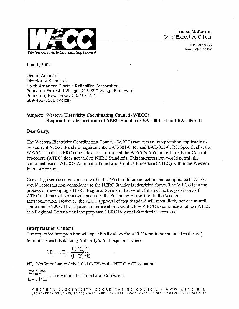


Maureen E. Long Standards Process Manager
July 9, 2007
TO: REGISTERED BALLOT BODY Ladies and Gentlemen: Announcement: Ballot Window for Withdrawal of WECC Waiver for INT-001 and INT-004;
Pre-ballot Window and Ballot Pool for Interpretation of BAL-001 and BAL-003 Open July 9, 2007
The Standards Committee (SC) announces the following:
Ballot Window for Withdrawal of ‘WECC Tagging Dynamic Schedules and Inadvertent Payback Waiver’ Open July 9–18, 2007 The FERC Order 693 did not include approval of the WECC Tagging Dynamic Schedules and Inadvertent Payback Waiver dated November 21, 2002, which is included in reliability standard INT-001-2 — Interchange Information and INT-004-1 — Dynamic Interchange Transaction Modifications. To remove this waiver as rapidly as possible, the Standards Committee authorized an Urgent Action SAR to Withdraw the WECC Waiver. The proposed modifications to INT-001 and INT-004 are limited to removal of the WECC waiver. The ballot will be open through 8 p.m. (EDT) on Wednesday, July18, 2007.
Pre-ballot Window and Ballot Pool for Interpretation of BAL-001-0, Requirement 1 and BAL-003-0, Requirement 3 both Open July 9, 2007 The Western Electricity Coordinating Council (WECC) submitted a Request for an Interpretation of BAL-001-0 — Real Power Balancing Control Performance and BAL-003-0 — Frequency Response and Bias. The request asked if the use of the WECC Automatic Time Error Correction (WATEC) procedure violates Requirement 1 of BAL-001-0 or Requirement 3 of BAL-003-0.
The Interpretation clarifies that use of the WATEC procedure does not violate either Requirement 1 of BAL-001-0 or Requirement 3 of BAL-003.
A new ballot pool to vote on this interpretation has been formed and will remain open up until 8 a.m. (EDT) Tuesday, August 7, 2007. During the pre-ballot window, members of the ballot pool may communicate with one another by using their “ballot pool list server.” The list server for this ballot pool is: [email protected]
The initial ballot for this interpretation will begin at 8 a.m. (EDT) on Tuesday, August 7, 2007.
Standards Development Process The Reliability Standards Development Procedure contains all the procedures governing the standards development process. The success of the NERC standards development process depends on stakeholder participation. We extend our thanks to all those who participate. If you have any questions, please contact me at 813-468-5998 or [email protected].
Sincerely,
Maureen E. Long cc: Registered Ballot Body Registered Users Standards Mailing List NERC Roster
116-390 Village Boulevard, Princeton, New Jersey 08540-5721
Phone: 609.452.8060 ▪ Fax: 609.452.9550 ▪ www.nerc.com

Maureen E. Long Standards Process Manager
August 27, 2007
TO: REGISTERED BALLOT BODY Ladies and Gentlemen:
Announcement: Initial Ballot Window Opens August 27, 2007
The Standards Committee (SC) announces the following standards action: Initial Ballot Window for Interpretation of BAL-003-0 Requirements R2, R2.2, R5, and R5.1 Opens August 27, 2007 The Electric Reliability Council of Texas (ERCOT) submitted a Request for an Interpretation of BAL-003-0 — Frequency Response and Bias Requirements 2, 2.2, 5, and 5.1. The request asked if there was a conflict between Requirement 2, which allows use of a variable bias setting and Requirement 5, which does not specifically address the use of a variable bias setting.
The Interpretation clarifies that in reliability standard BAL-003-0, Requirements 2 and 5 do not conflict with one another.
The initial ballot for this interpretation is open and will close at 8 p.m. (EDT) on Wednesday, September 5, 2007. Standards Development Process The Reliability Standards Development Procedure contains all the procedures governing the standards development process. The success of the NERC standards development process depends on stakeholder participation. We extend our thanks to all those who participate. If you have any questions, please contact me at 813-468-5998 or [email protected].
Sincerely,
Maureen E. Long cc: Registered Ballot Body Registered Users Standards Mailing List NERC Roster
116-390 Village Boulevard, Princeton, New Jersey 08540-5721
Phone: 609.452.8060 ▪ Fax: 609.452.9550 ▪ www.nerc.com

Maureen E. Long Standards Process Manager
August 17, 2007
TO: REGISTERED BALLOT BODY Ladies and Gentlemen:
Announcement of Initial Ballot Results
The Standards Committee (SC) announces the following:
Initial Ballot Results for Interpretation of BAL-001-0 R1 and BAL-003-0 R3 The initial ballot for the Interpretation of BAL-001-0 — Real Power Balancing Control Performance, Requirement 1 and BAL-003-0 — Frequency Response and Bias, Requirement 3 was conducted from August 7 through August 16, 2007.
The Interpretation answered the question, “Does the WECC Automatic Time Error Control (WATEC) Procedure violate Requirement 1 of BAL-001-0 or Requirement 3 of BAL-003-0?”
The ballot achieved a quorum; however, there was a negative ballot with a comment, initiating the need to undergo a re-circulation ballot. The drafting team will be reviewing comments submitted with the ballot and preparing its consideration of those comments. (Detailed Ballot Results)
Quorum: 92.68 % Approval: 97.91 %
Standards Development Process The Reliability Standards Development Procedure contains all the procedures governing the standards development process. The success of the NERC standards development process depends on stakeholder participation. We extend our thanks to all those who participate. If you have any questions, please contact me at 813-468-5998 or [email protected].
Sincerely,
Maureen E. Long cc: Registered Ballot Body Registered Users Standards Mailing List NERC Roster
116-390 Village Boulevard, Princeton, New Jersey 08540-5721
Phone: 609.452.8060 ▪ Fax: 609.452.9550 ▪ www.nerc.com

Regions | Committees | Meetings | Search | Site Map | Contact Us
Reliability Standards
User Name
Password
Log in
Register Reliability Standards HomeAnnouncements BOT Approved StandardsRegulatory Approved StandardsStandards Under DevelopmentBallot PoolsCurrent BallotsBallot ResultsRegistered Ballot BodyProxy VotersRegistration InstructionsRegional Reliability Standards NERC Home
Ballot Results
Ballot Name:Interpretation Request - BAL-001-0, R1 and BAL-003-0, R3_in
Ballot Period: 8/7/2007 - 8/16/2007
Ballot Type: Initial
Total # Votes: 152
Total Ballot Pool: 164
Quorum: 92.68 % The Quorum has been reached
Weighted Segment Vote:
97.91 %
Ballot Results: The standard will proceed to recirculation ballot.
Summary of Ballot Results
Segment Ballot Pool
Segment Weight
Affirmative Negative Abstain
No Vote
# Votes Fraction
# Votes Fraction
# Votes
1 - Segment 1. 49 1 37 0.974 1 0.026 5 62 - Segment 2. 9 0.8 8 0.8 0 0 0 13 - Segment 3. 34 1 32 1 0 0 2 04 - Segment 4. 8 0.8 8 0.8 0 0 0 05 - Segment 5. 24 1 17 0.944 1 0.056 6 06 - Segment 6. 20 1 15 0.938 1 0.063 3 17 - Segment 7. 1 0.1 1 0.1 0 0 0 08 - Segment 8. 5 0.2 2 0.2 0 0 2 19 - Segment 9. 8 0.6 6 0.6 0 0 0 210 - Segment 10. 6 0.4 4 0.4 0 0 1 1
Totals 164 6.9 130 6.756 3 0.145 19 12
Individual Ballot Pool Results
Segment Organization Member Ballot Comments
1AEP Service Corp. -- Transmission System AEP
Scott P. Moore Abstain
1 Ameren Services Company Kirit S Shah Affirmative 1 American Public Power Association E. Nick Henery Affirmative 1 Arizona Public Service Co. Cary B. Deise Affirmative 1 Avista Corp. Scott Kinney Affirmative 1 Basin Electric Power Cooperative David Rudolph Affirmative 1 Bonneville Power Administration Donald S. Watkins
1Consolidated Edison Co. of New York
Edwin E. Thompson PE
1 Duke Energy Doug Hils Affirmative View
Page 1 of 5Untitled Page
8/17/2007https://standards.nerc.net/BallotResults.aspx?BallotGUID=7fd9ac06-f3f4-4762-92a1-4af2...

1 East Kentucky Power Coop. George S. Carruba Affirmative 1 FirstEnergy Energy Delivery Robert Martinko Affirmative
1Florida Keys Electric Cooperative Assoc.
Dennis Minton
1 Florida Power & Light Co. C. Martin Mennes Affirmative 1 Gainesville Regional Utilities Luther E. Fair1 Great River Energy Gordon Pietsch
1Hoosier Energy Rural Electric Cooperative, Inc.
Damon Holladay Affirmative
1 Hydro One Networks, Inc. Ajay Garg Affirmative 1 Idaho Power Company Ronald D. Schellberg Affirmative 1 Kansas City Power & Light Co. Jim Useldinger Affirmative 1 Keyspan LIPA Richard J. Bolbrock Abstain 1 Lincoln Electric System Doug Bantam Affirmative 1 Minnesota Power, Inc. Carol Gerou Affirmative
1Municipal Electric Authority of Georgia
Jerry J Tang Affirmative
1New Brunswick Power Transmission Corporation
Wayne N. Snowdon Affirmative
1 New York Power Authority Ralph Rufrano Affirmative 1 Northeast Utilities David H. Boguslawski Abstain 1 Northern Indiana Public Service Co. Joseph Dobes Affirmative 1 Oncor Electric Delivery Charles W. Jenkins Affirmative 1 Otter Tail Power Company Lawrence R. Larson Affirmative 1 Pacific Gas and Electric Company Chifong L. Thomas Affirmative 1 PacifiCorp Robert Williams Affirmative 1 Potomac Electric Power Co. Richard J. Kafka Affirmative 1 PP&L, Inc. Ray Mammarella Abstain
1Public Service Company of New Mexico
Keith Nix Affirmative
1 Sacramento Municipal Utility District Dilip Mahendra Affirmative 1 Salt River Project Robert Kondziolka Affirmative 1 San Diego Gas & Electric Linda Brown Affirmative 1 Santee Cooper Terry L. Blackwell Affirmative 1 SaskPower Wayne Guttormson Abstain 1 Seattle City Light Christopher M. Turner Affirmative 1 Sierra Pacific Power Co. Richard Salgo Affirmative 1 Southern California Edison Co. Dana Cabbell Affirmative
1 Southern Company Services, Inc.Horace Stephen Williamson
Affirmative
1 Southwest Transmission Coop., Inc. Alan H. Wilkinson Affirmative
1Sunflower Electric Power Corporation
Noman Lee Williams
1 Tennessee Valley Authority Larry G. Akens Affirmative 1 Tri-State G & T Association Inc. Bruce A Sembrick Affirmative 1 Tucson Electric Power Co. Ronald P. Belval Affirmative 1 Xcel Energy, Inc. Gregory L. Pieper Negative 2 Alberta Electric System Operator Anita Lee Affirmative
2British Columbia Transmission Corporation
Phil Park Affirmative
2 California ISO David Hawkins Affirmative
2Independent Electricity System Operator
Don Tench Affirmative
2 ISO New England, Inc. Kathleen Goodman Affirmative 2 Midwest ISO, Inc. Terry Bilke Affirmative 2 New Brunswick System Operator Alden Briggs Affirmative
2New York Independent System Operator
Gregory Campoli
2 PJM Interconnection, L.L.C. Tom Bowe Affirmative
Page 2 of 5Untitled Page
8/17/2007https://standards.nerc.net/BallotResults.aspx?BallotGUID=7fd9ac06-f3f4-4762-92a1-4af2...

3 Alabama Power Company Robin Hurst Affirmative 3 Arizona Public Service Co. Thomas R. Glock Affirmative 3 Atlantic City Electric Company James V. Petrella Affirmative 3 Bonneville Power Administration Rebecca Berdahl Affirmative 3 City of Tallahassee Rusty S. Foster Affirmative 3 Consumers Energy Co. David A. Lapinski Affirmative 3 Delmarva Power & Light Co. Michael R. Mayer Affirmative 3 Dominion Resources, Inc. Jalal (John) Babik Affirmative 3 Duke Energy Henry Ernst-Jr Affirmative 3 Entergy Services, Inc. Matt Wolf Affirmative 3 Farmington Electric Utility System Alan Glazner Affirmative
3 FirstEnergy SolutionsJoanne Kathleen Borrell
Affirmative
3 Florida Municipal Power Agency Michael Alexander Affirmative 3 Florida Power Corporation Lee Schuster Affirmative 3 Georgia Power Company Leslie Sibert Affirmative 3 Gulf Power Company William F. Pope Affirmative 3 Hydro One Networks, Inc. Michael D. Penstone Affirmative 3 Lincoln Electric System Bruce Merrill Affirmative 3 Louisville Gas and Electric Co. Charles A. Freibert Affirmative 3 MidAmerican Energy Co. Thomas C. Mielnik Affirmative 3 Mississippi Power Don Horsley Affirmative
3 New York Power AuthorityChristopher Lawrence de Graffenried
Affirmative
3 Orlando Utilities Commission Ballard Keith Mutters Abstain 3 Platte River Power Authority Terry L Baker Affirmative 3 Potomac Electric Power Co. Robert Reuter Affirmative
3Public Utility District No. 1 of Chelan County
Kenneth R. Johnson Affirmative
3Public Utility District No. 2 of Grant County
Greg Lange Affirmative
3 Salt River Project John T. Underhill Affirmative 3 San Diego Gas & Electric Scott Peterson Affirmative 3 Santee Cooper Zack Dusenbury Affirmative 3 Seattle City Light Dana Wheelock Affirmative 3 Tennessee Valley Authority Cynthia Herron Affirmative 3 Tri-State G & T Association Inc. Dillwyn H. Ramsay Abstain 3 Wisconsin Electric Power Marketing James R. Keller Affirmative 4 Consumers Energy Co. David Frank Ronk Affirmative 4 Florida Municipal Power Agency William S. May Affirmative 4 Northern California Power Agency Fred E. Young Affirmative 4 Old Dominion Electric Coop. Mark Ringhausen Affirmative
4Public Utility District No. 2 of Grant County
Kevin J. Conway Affirmative
4 Seattle City Light Hao Li Affirmative 4 Seminole Electric Cooperative, Inc. Steven R. Wallace Affirmative 4 Wisconsin Energy Corp. Anthony Jankowski Affirmative 5 AEP Service Corp. Brock Ondayko Abstain 5 Alabama Electric Coop. Inc. Tim Hattaway Abstain 5 Avista Corp. Edward F. Groce Affirmative 5 BC Hydro and Power Authority Clement Ma Affirmative 5 Bonneville Power Administration Francis J. Halpin Affirmative 5 City of Tallahassee Alan Gale Affirmative
5City Water, Light & Power of Springfield
Karl E. Kohlrus Affirmative
5 Conectiv Energy Supply, Inc. Richard K Douglass Affirmative 5 Detroit Edison Company Ronald W. Bauer Affirmative 5 Entegra Power Group, LLC Kenneth Parker Affirmative
Page 3 of 5Untitled Page
8/17/2007https://standards.nerc.net/BallotResults.aspx?BallotGUID=7fd9ac06-f3f4-4762-92a1-4af2...

5 Florida Municipal Power Agency Douglas Keegan Affirmative 5 Lincoln Electric System Dennis Florom Affirmative 5 Louisville Gas and Electric Co. Charlie Martin Affirmative 5 New York Power Authority Richard J Ardolino Abstain 5 Oklahoma Gas and Electric Co. Kim Morphis Abstain 5 PPL Generation LLC Mark A. Heimbach Abstain 5 Reliant Energy Services Thomas J. Bradish Affirmative 5 Salt River Project Glen Reeves Affirmative 5 Seminole Electric Cooperative, Inc. Brenda K Atkins Abstain 5 Southern Company Services, Inc. Roger D. Green Affirmative 5 Tenaska, Inc. Scott M. Helyer Affirmative
5U.S. Army Corps of Engineers Northwestern Division
Karl Bryan Affirmative
5 Wisconsin Electric Power Co. Linda Horn Affirmative 5 Xcel Energy, Inc. Stephen J. Beuning Negative 6 AEP Service Corp. Dana E. Horton Abstain 6 Black Hills Power Larry Williamson Affirmative 6 Bonneville Power Administration Brenda S. Anderson Affirmative 6 Entergy Services, Inc. William Franklin Affirmative 6 First Energy Solutions Alfred G Roth Affirmative 6 Florida Municipal Power Agency Robert C. Williams Affirmative 6 Great River Energy Donna Stephenson Abstain 6 Lincoln Electric System Eric Ruskamp Affirmative 6 Louisville Gas and Electric Co. Daryn Barker Affirmative 6 Progress Energy Carolinas James Eckelkamp Abstain
6Public Utility District No. 1 of Chelan County
Hugh A. Owen Affirmative
6 Sacramento Municipal Utility DistrictRobert D. Schwermann
Affirmative
6 Salt River Project Mike Hummel Affirmative 6 Santee Cooper Suzanne Ritter Affirmative 6 Seminole Electric Cooperative, Inc. Trudy S. Novak Affirmative 6 South Carolina Electric & Gas Co. Matt Hammond Affirmative
6Southern Company Generation and Energy Marketing
J. Roman Carter Affirmative
6 Tampa Electric Co. Jose Benjamin Quintas
6Western Area Power Administration - UGP Marketing
John Stonebarger Affirmative
6 Xcel Energy, Inc. David F. Lemmons Negative View 7 Eastman Chemical Company Lloyd Webb Affirmative 8 Energy Mark, Inc. Howard F. Illian Abstain View 8 JDRJC Associates Jim D. Cyrulewski Affirmative
8North Carolina Utilities Commission Public Staff
Jack Floyd Affirmative
8 Other Michehl R. Gent8 Prague Power, LLC William Lohrman Abstain
9 California Energy CommissionWilliam Mitchell Chamberlain
Affirmative View
9 Colorado Public Utilities Commission Jeffrey (Jeff) Hein
9Commonwealth of Massachusetts Department of Public Utilities
Donald E. Nelson Affirmative
9National Association of Regulatory Utility Commissioners
Diane J. Barney Affirmative
9New York State Public Service Commission
James T. Gallagher Affirmative
9 North Carolina Utilities Commission Sam Watson Affirmative 9 Public Utilities Commission of Ohio Klaus Lambeck Affirmative
9Wyoming Public Service Commission
Kathleen A. Lewis
Page 4 of 5Untitled Page
8/17/2007https://standards.nerc.net/BallotResults.aspx?BallotGUID=7fd9ac06-f3f4-4762-92a1-4af2...
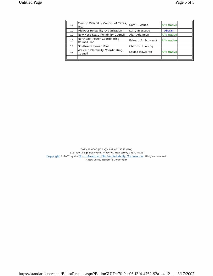
10Electric Reliability Council of Texas, Inc.
Sam R. Jones Affirmative
10 Midwest Reliability Organization Larry Brusseau Abstain 10 New York State Reliability Council Alan Adamson Affirmative
10Northeast Power Coordinating Council, Inc.
Edward A. Schwerdt Affirmative
10 Southwest Power Pool Charles H. Yeung
10Western Electricity Coordinating Council
Louise McCarren Affirmative
609.452.8060 (Voice) - 609.452.9550 (Fax)116-390 Village Boulevard, Princeton, New Jersey 08540-5721
Copyright © 2007 by the North American Electric Reliability Corporation. All rights reserved.A New Jersey Nonprofit Corporation
Page 5 of 5Untitled Page
8/17/2007https://standards.nerc.net/BallotResults.aspx?BallotGUID=7fd9ac06-f3f4-4762-92a1-4af2...

116-390 Village Boulevard, Princeton, New Jersey 08540-5721
Phone: 609.452.8060 ▪ Fax: 609.452.9550 ▪ www.nerc.com
Consideration of Comments on Initial Ballot of Interpretation for BAL-001-0 R1 and BAL-003-0 R3 Summary Consideration: The stakeholder comments submitted with initial ballots on the Interpretation of BAL-001-0 — Real Power Balancing Control Performance Requirement 1 and BAL-003-0 — Frequency Response and Bias Requirement 3 did not indicate a need to make any modifications to the interpretation and no changes were made. The Interpretation will proceed to a recirculation ballot.
Segment: 1
Organization: Duke Energy
Member: Doug Hils
Comment: Duke Energy agrees with the interpretation of the Resources Subcommittee which indicates that the WATEC procedure does not violate BAL-001-01 as long as raw ACE used for reporting of CPS compliance (and DCS) does not include the WATEC variable. To the extent that the interpretation requires the Balancing Authorities to calculate raw ACE differently than they had in the past, we would suggest that the WECC be provided some assurance by the WECC Balancing Authorities, perhaps a self-certification, that raw ACE is being calculated in accordance with the standards and the clarification provided in the interpretation.
Response: We agree that the calculation of all BA’s CPS and ACE should be validated. In this case, the WECC provided procedural information that showed BAs were instructed to report CPS via raw ACE and control to a WATEC-adjusted ACE. Validation of ACE and CPS should occur as part of normal compliance audits.
Segment: 6
Organization: Xcel Energy, Inc.
Member: David F. Lemmons
Comment: Xcel Energy is concerned with the interpretation in that it appears that one region will require an ACE calculation that differs from the NERC ACE while all compliance will be determined with the NERC ACE. This causes the potential to violate the NERC standard while operating to the WECC operating requirement. This is an unreasonable position to be put in by the standards organizations. Anytime standards are in conflict with each other, the organizations subject to these standards are put in an untenable position. Reporting of compliance with the standards should be on the basis of the required operating basis. In this exact instance, with WECC requiring operation using a different ACE calculation, WECC entities should be reporting compliance based on the WECC ACE used for operation, not the NERC ACE. If NERC feels that the WECC ACE is not sufficient for reliable operation in meeting CPS and DCS, the the WECC members should not be asked to operate using this method. If NERC is not concerned with this issue, WECC entities should report compliance with CPS and DCS using the WECC ACE.
Response: CPS (as calculated via raw ACE) measures a Balancing Authority’s impact on frequency. To measure CPS using another value, would misstate impact on reliability. There are many other similar situations where BAs operate with both a control ACE and a “CPS” ACE. Many BAs employ a different control ACE to pay back inadvertent, maximize CPS, do inadvertent payback when it makes financial sense, to minimize directional changes on generators, etc.. As long as impact on frequency is measured reported via raw ACE, all BAs are measured the same way to the same expectation. We understand WECC is going through the standards drafting process to formalize the WECC procedure as a NERC and FERC approved standard. Once this has occurred, the WATEC control ACE will also be the NERC reporting ACE.

Consideration of Comments on Initial Ballot of Interpretation of BAL-001 R1 and BAL-003 R3
Page 2 of 2 August 23, 2007
Segment: 8
Organization: Energy Mark, Inc.
Member: Howard F. Illian
Comment: My concern is with the possible interaction between the current NERC Standards (BAL-001) and the WECC Standard on ATEC. The WECC ATEC Standard does not have a compliance measure associated with it. Therefore, there is no way to insure that the standards will not conflict with each other. If WECC adds a compliance measure at a later date, it could result in a conflict that cannot be corrected without changing the WECC ATEC Standard. If this is necessary, this information should be made available now and considered as part of this interpretation.
Response: We view WATEC as a procedure (rather than a standard) that the WECC uses to achieve a comparability goal. WATEC reduces inadvertent balances and does payback when prices are generally the same. There is a measure associated with BAL-001, that being CPS. As long as BAs calculate and report their performance using raw ACE, their impact on reliability is measured. From a procedural standpoint, an interpretation of a standard is not the mechanism to add compliance elements. We recommend this suggestion be raised as the “Balancing Authority Controls (Project 2007-05)” goes through standard drafting. We understand WECC is going through the standards drafting process to formalize the WECC procedure as a NERC and FERC approved standard. Once this has occurred, the WATEC control ACE will also be the NERC reporting ACE.
Segment: 9
Organization: California Energy Commission
Member: William Mitchell Chamberlain
Comment: This interpretation is important to allow those Interconnections that wish to use automatic time error correction to do so without fear of being sanctioned. The interpretation does not adversely affect any party in other interconnections.
Response: We agree. Similarly, other Interconnections could develop alternative Time and Payback procedures that achieve their respective objectives. Thank you for your comment.

Maureen E. Long Standards Process Manager
August 23, 2007
TO: REGISTERED BALLOT BODY Ladies and Gentlemen:
Announcement: Recirculation Ballot Window Opens and Final Ballot Results
The Standards Committee (SC) announces the following:
Recirculation Ballot Window for Interpretation of BAL-001-0 Requirement 1 and BAL-003-0 Requirement 3 Opens August 23, 2007 The Western Electricity Coordinating Council (WECC) submitted a Request for an Interpretation of BAL-001-0 — Real Power Balancing Control Performance and BAL-003-0 — Frequency Response and Bias. The request asked if the use of the WECC Automatic Time Error Correction (WATEC) procedure violates Requirement 1 of BAL-001-0 or Requirement 3 of BAL-003-0. The Interpretation clarifies that use of the WATEC procedure does not violate either Requirement 1 of BAL-001-0 or Requirement 3 of BAL-003. The initial ballot for this interpretation was conducted from August 7–16, 2007 and achieved a quorum; however, there was a negative ballot with a comment, initiating the need for a recirculation ballot. The drafting team that developed the Interpretation has considered these comments and posted its responses. All members of the ballot pool are encouraged to review the comments submitted with the initial ballot and the responses to those comments.
The recirculation ballot is open through 8 p.m. (EDT) Saturday, September 1, 2007.
Members of the ballot pool may:
- Reconsider and change their vote from the first ballot.
- Vote in the second ballot even if they did not vote on the first ballot.
- Take no action if they do not want to change their original vote.
In the recirculation ballot, votes are counted by exception only — if members don’t indicate a revision to their original votes, the vote remains the same as in the first ballot. Final Ballot Results for Removal of WECC Waiver from INT-001 and INT-004 The recirculation ballot for the Urgent Action SAR to Withdraw the WECC Waiver (Tagging Dynamic Schedules and Inadvertent Payback Waiver) from INT-001 and INT-004 was conducted from August 13–22, 2007 and the ballot was approved. (Detailed Ballot Results)
Quorum: 78.57 % Approval: 99.17%
116-390 Village Boulevard, Princeton, New Jersey 08540-5721
Phone: 609.452.8060 ▪ Fax: 609.452.9550 ▪ www.nerc.com

REGISTERED BALLOT BODY August 23, 2007 Page Two Standards Development Process The Reliability Standards Development Procedure contains all the procedures governing the standards development process. The success of the NERC standards development process depends on stakeholder participation. We extend our thanks to all those who participate. If you have any questions, please contact me at 813-468-5998 or [email protected].
Sincerely,
Maureen E. Long cc: Registered Ballot Body Registered Users Standards Mailing List NERC Roster

Maureen E. Long Standards Process Manager
September 4, 2007
TO: REGISTERED BALLOT BODY Ladies and Gentlemen:
Announcement of Ballot Results
The Standards Committee (SC) announces the following:
Initial Ballot Results for IRO-006-4 — Reliability Coordination — Transmission Loading Relief The initial ballot for the first phase of modifications to IRO-006-4 — Reliability Coordination — Transmission Loading Relief was conducted from August 20 through August 29, 2007.
The first phase of revisions included working with NAESB to remove all business practices from IRO-006 and then to add measures and compliance elements to support the remaining reliability-related requirements. Future phases of the project will address a broader range of improvements.
The ballot achieved a quorum however there were some negative ballots with comments. The drafting team will review comments submitted with the ballot and will prepare its consideration of those comments. If the drafting team modifies the standard based on comments submitted with the initial ballot, the standard will be posted for an additional comment period; if the drafting team does not make any modifications to the standard, the standard will proceed to a recirculation ballot. (Detailed Ballot Results)
Quorum: 92.70 % Approval: 93.52 %
Final Ballot Results for Interpretation of BAL-001-0 R1 and BAL-003-0 R3 The recirculation ballot for the Interpretation of BAL-001-0 — Real Power Balancing Control Performance, Requirement 1 and BAL-003-0 — Frequency Response and Bias, Requirement 3 was conducted from August 23 through September 1, 2007 and the ballot was approved. (Detailed Ballot Results)
Quorum: 96.34 % Approval: 97.21 %
The Interpretation answered the question, “Does the WECC Automatic Time Error Control (WATEC) Procedure violate Requirement 1 of BAL-001-0 or Requirement 3 of BAL-003-0?”
Standards Development Process The Reliability Standards Development Procedure contains all the procedures governing the standards development process. The success of the NERC standards development process depends on stakeholder participation. We extend our thanks to all those who participate. If you have any questions, please contact me at 813-468-5998 or [email protected].
Sincerely,
Maureen E. Long cc: Registered Ballot Body Registered Users Standards Mailing List NERC Roster
116-390 Village Boulevard, Princeton, New Jersey 08540-5721
Phone: 609.452.8060 ▪ Fax: 609.452.9550 ▪ www.nerc.com

Regions | Committees | Meetings | Search | Site Map | Contact Us
Reliability Standards
User Name
Password
Log in
Register Reliability Standards HomeAnnouncements BOT Approved StandardsRegulatory Approved StandardsStandards Under DevelopmentBallot PoolsCurrent BallotsBallot ResultsRegistered Ballot BodyProxy VotersRegistration InstructionsRegional Reliability Standards NERC Home
Ballot Results
Ballot Name:Interpretation Request - BAL-001-0, R1 and BAL-003-0, R3_rc
Ballot Period: 8/23/2007 - 9/1/2007
Ballot Type: recirculation
Total # Votes: 158
Total Ballot Pool: 164
Quorum: 96.34 % The Quorum has been reached
Weighted Segment Vote:
97.21 %
Ballot Results: The Standard has Passed
Summary of Ballot Results
Segment Ballot Pool
Segment Weight
Affirmative Negative Abstain
No Vote
# Votes Fraction
# Votes Fraction
# Votes
1 - Segment 1. 49 1 40 0.976 1 0.024 5 32 - Segment 2. 9 0.8 8 0.8 0 0 0 13 - Segment 3. 34 1 32 1 0 0 2 04 - Segment 4. 8 0.8 8 0.8 0 0 0 05 - Segment 5. 24 1 17 0.944 1 0.056 6 06 - Segment 6. 20 1 15 0.882 2 0.118 3 07 - Segment 7. 1 0.1 1 0.1 0 0 0 08 - Segment 8. 5 0.3 3 0.3 0 0 2 09 - Segment 9. 8 0.6 6 0.6 0 0 0 210 - Segment 10. 6 0.5 5 0.5 0 0 1 0
Totals 164 7.1 135 6.902 4 0.198 19 6
Individual Ballot Pool Results
Segment Organization Member Ballot Comments
1AEP Service Corp. -- Transmission System AEP
Scott P. Moore Abstain
1 Ameren Services Company Kirit S Shah Affirmative 1 American Public Power Association E. Nick Henery Affirmative 1 Arizona Public Service Co. Cary B. Deise Affirmative 1 Avista Corp. Scott Kinney Affirmative 1 Basin Electric Power Cooperative David Rudolph Affirmative 1 Bonneville Power Administration Donald S. Watkins Affirmative
1Consolidated Edison Co. of New York
Edwin E. Thompson PE
1 Duke Energy Doug Hils Affirmative View
Page 1 of 5Untitled Page
9/4/2007https://standards.nerc.net/BallotResults.aspx?BallotGUID=3ae650b2-fcee-46b4-8f73-2c7ea...

1 East Kentucky Power Coop. George S. Carruba Affirmative 1 FirstEnergy Energy Delivery Robert Martinko Affirmative
1Florida Keys Electric Cooperative Assoc.
Dennis Minton Abstain
1 Florida Power & Light Co. C. Martin Mennes Affirmative 1 Gainesville Regional Utilities Luther E. Fair Affirmative 1 Great River Energy Gordon Pietsch
1Hoosier Energy Rural Electric Cooperative, Inc.
Damon Holladay Affirmative
1 Hydro One Networks, Inc. Ajay Garg Affirmative 1 Idaho Power Company Ronald D. Schellberg Affirmative 1 Kansas City Power & Light Co. Jim Useldinger Affirmative 1 Keyspan LIPA Richard J. Bolbrock Abstain 1 Lincoln Electric System Doug Bantam Affirmative 1 Minnesota Power, Inc. Carol Gerou Affirmative
1Municipal Electric Authority of Georgia
Jerry J Tang Affirmative
1New Brunswick Power Transmission Corporation
Wayne N. Snowdon Affirmative
1 New York Power Authority Ralph Rufrano Affirmative 1 Northeast Utilities David H. Boguslawski Affirmative 1 Northern Indiana Public Service Co. Joseph Dobes Affirmative 1 Oncor Electric Delivery Charles W. Jenkins Affirmative 1 Otter Tail Power Company Lawrence R. Larson Affirmative 1 Pacific Gas and Electric Company Chifong L. Thomas Affirmative 1 PacifiCorp Robert Williams Affirmative 1 Potomac Electric Power Co. Richard J. Kafka Affirmative 1 PP&L, Inc. Ray Mammarella Affirmative
1Public Service Company of New Mexico
Keith Nix Affirmative
1 Sacramento Municipal Utility District Dilip Mahendra Affirmative 1 Salt River Project Robert Kondziolka Affirmative 1 San Diego Gas & Electric Linda Brown Abstain 1 Santee Cooper Terry L. Blackwell Affirmative 1 SaskPower Wayne Guttormson Abstain 1 Seattle City Light Christopher M. Turner Affirmative 1 Sierra Pacific Power Co. Richard Salgo Affirmative 1 Southern California Edison Co. Dana Cabbell Affirmative
1 Southern Company Services, Inc.Horace Stephen Williamson
Affirmative
1 Southwest Transmission Coop., Inc. Alan H. Wilkinson Affirmative
1Sunflower Electric Power Corporation
Noman Lee Williams
1 Tennessee Valley Authority Larry G. Akens Affirmative 1 Tri-State G & T Association Inc. Bruce A Sembrick Affirmative 1 Tucson Electric Power Co. Ronald P. Belval Affirmative 1 Xcel Energy, Inc. Gregory L. Pieper Negative 2 Alberta Electric System Operator Anita Lee Affirmative
2British Columbia Transmission Corporation
Phil Park Affirmative
2 California ISO David Hawkins Affirmative
2Independent Electricity System Operator
Don Tench Affirmative
2 ISO New England, Inc. Kathleen Goodman Affirmative 2 Midwest ISO, Inc. Terry Bilke Affirmative 2 New Brunswick System Operator Alden Briggs Affirmative
2New York Independent System Operator
Gregory Campoli
2 PJM Interconnection, L.L.C. Tom Bowe Affirmative
Page 2 of 5Untitled Page
9/4/2007https://standards.nerc.net/BallotResults.aspx?BallotGUID=3ae650b2-fcee-46b4-8f73-2c7ea...

3 Alabama Power Company Robin Hurst Affirmative 3 Arizona Public Service Co. Thomas R. Glock Affirmative 3 Atlantic City Electric Company James V. Petrella Affirmative 3 Bonneville Power Administration Rebecca Berdahl Affirmative 3 City of Tallahassee Rusty S. Foster Affirmative 3 Consumers Energy Co. David A. Lapinski Affirmative 3 Delmarva Power & Light Co. Michael R. Mayer Affirmative 3 Dominion Resources, Inc. Jalal (John) Babik Affirmative 3 Duke Energy Henry Ernst-Jr Affirmative 3 Entergy Services, Inc. Matt Wolf Affirmative 3 Farmington Electric Utility System Alan Glazner Affirmative
3 FirstEnergy SolutionsJoanne Kathleen Borrell
Affirmative
3 Florida Municipal Power Agency Michael Alexander Affirmative 3 Florida Power Corporation Lee Schuster Affirmative 3 Georgia Power Company Leslie Sibert Affirmative 3 Gulf Power Company William F. Pope Affirmative 3 Hydro One Networks, Inc. Michael D. Penstone Affirmative 3 Lincoln Electric System Bruce Merrill Affirmative 3 Louisville Gas and Electric Co. Charles A. Freibert Affirmative 3 MidAmerican Energy Co. Thomas C. Mielnik Affirmative 3 Mississippi Power Don Horsley Affirmative
3 New York Power AuthorityChristopher Lawrence de Graffenried
Abstain
3 Orlando Utilities Commission Ballard Keith Mutters Affirmative 3 Platte River Power Authority Terry L Baker Affirmative 3 Potomac Electric Power Co. Robert Reuter Affirmative
3Public Utility District No. 1 of Chelan County
Kenneth R. Johnson Affirmative
3Public Utility District No. 2 of Grant County
Greg Lange Affirmative
3 Salt River Project John T. Underhill Affirmative 3 San Diego Gas & Electric Scott Peterson Affirmative 3 Santee Cooper Zack Dusenbury Affirmative 3 Seattle City Light Dana Wheelock Affirmative 3 Tennessee Valley Authority Cynthia Herron Affirmative 3 Tri-State G & T Association Inc. Dillwyn H. Ramsay Abstain 3 Wisconsin Electric Power Marketing James R. Keller Affirmative 4 Consumers Energy Co. David Frank Ronk Affirmative 4 Florida Municipal Power Agency William S. May Affirmative 4 Northern California Power Agency Fred E. Young Affirmative 4 Old Dominion Electric Coop. Mark Ringhausen Affirmative
4Public Utility District No. 2 of Grant County
Kevin J. Conway Affirmative
4 Seattle City Light Hao Li Affirmative 4 Seminole Electric Cooperative, Inc. Steven R. Wallace Affirmative 4 Wisconsin Energy Corp. Anthony Jankowski Affirmative 5 AEP Service Corp. Brock Ondayko Abstain 5 Alabama Electric Coop. Inc. Tim Hattaway Abstain 5 Avista Corp. Edward F. Groce Affirmative 5 BC Hydro and Power Authority Clement Ma Affirmative 5 Bonneville Power Administration Francis J. Halpin Affirmative 5 City of Tallahassee Alan Gale Affirmative
5City Water, Light & Power of Springfield
Karl E. Kohlrus Affirmative
5 Conectiv Energy Supply, Inc. Richard K Douglass Affirmative 5 Detroit Edison Company Ronald W. Bauer Affirmative 5 Entegra Power Group, LLC Kenneth Parker Affirmative
Page 3 of 5Untitled Page
9/4/2007https://standards.nerc.net/BallotResults.aspx?BallotGUID=3ae650b2-fcee-46b4-8f73-2c7ea...

5 Florida Municipal Power Agency Douglas Keegan Affirmative 5 Lincoln Electric System Dennis Florom Affirmative 5 Louisville Gas and Electric Co. Charlie Martin Affirmative 5 New York Power Authority Richard J Ardolino Affirmative 5 Oklahoma Gas and Electric Co. Kim Morphis Abstain 5 PPL Generation LLC Mark A. Heimbach Abstain 5 Reliant Energy Services Thomas J. Bradish Affirmative 5 Salt River Project Glen Reeves Affirmative 5 Seminole Electric Cooperative, Inc. Brenda K Atkins Abstain 5 Southern Company Services, Inc. Roger D. Green Affirmative 5 Tenaska, Inc. Scott M. Helyer Abstain
5U.S. Army Corps of Engineers Northwestern Division
Karl Bryan Affirmative
5 Wisconsin Electric Power Co. Linda Horn Affirmative 5 Xcel Energy, Inc. Stephen J. Beuning Negative 6 AEP Service Corp. Dana E. Horton Abstain 6 Black Hills Power Larry Williamson Affirmative 6 Bonneville Power Administration Brenda S. Anderson Affirmative 6 Entergy Services, Inc. William Franklin Affirmative 6 First Energy Solutions Alfred G. Roth Affirmative 6 Florida Municipal Power Agency Robert C. Williams Affirmative 6 Great River Energy Donna Stephenson Abstain 6 Lincoln Electric System Eric Ruskamp Affirmative 6 Louisville Gas and Electric Co. Daryn Barker Affirmative 6 Progress Energy Carolinas James Eckelkamp Abstain
6Public Utility District No. 1 of Chelan County
Hugh A. Owen Affirmative
6 Sacramento Municipal Utility DistrictRobert D. Schwermann
Affirmative
6 Salt River Project Mike Hummel Affirmative 6 Santee Cooper Suzanne Ritter Affirmative 6 Seminole Electric Cooperative, Inc. Trudy S. Novak Affirmative 6 South Carolina Electric & Gas Co. Matt Hammond Affirmative
6Southern Company Generation and Energy Marketing
J. Roman Carter Affirmative
6 Tampa Electric Co. Jose Benjamin Quintas Negative
6Western Area Power Administration - UGP Marketing
John Stonebarger Affirmative
6 Xcel Energy, Inc. David F. Lemmons Negative View 7 Eastman Chemical Company Lloyd Webb Affirmative 8 Energy Mark, Inc. Howard F. Illian Abstain View 8 JDRJC Associates Jim D. Cyrulewski Affirmative
8North Carolina Utilities Commission Public Staff
Jack Floyd Affirmative
8 Other Michehl R. Gent Affirmative 8 Prague Power, LLC William Lohrman Abstain
9 California Energy CommissionWilliam Mitchell Chamberlain
Affirmative View
9 Colorado Public Utilities Commission Jeffrey (Jeff) Hein
9Commonwealth of Massachusetts Department of Public Utilities
Donald E. Nelson Affirmative
9National Association of Regulatory Utility Commissioners
Diane J. Barney Affirmative
9New York State Public Service Commission
James T. Gallagher Affirmative
9 North Carolina Utilities Commission Sam Watson Affirmative 9 Public Utilities Commission of Ohio Klaus Lambeck Affirmative
9Wyoming Public Service Commission
Kathleen A. Lewis
Page 4 of 5Untitled Page
9/4/2007https://standards.nerc.net/BallotResults.aspx?BallotGUID=3ae650b2-fcee-46b4-8f73-2c7ea...

10Electric Reliability Council of Texas, Inc.
Sam R. Jones Affirmative
10 Midwest Reliability Organization Larry Brusseau Abstain 10 New York State Reliability Council Alan Adamson Affirmative
10Northeast Power Coordinating Council, Inc.
Edward A. Schwerdt Affirmative
10 Southwest Power Pool Charles H. Yeung Affirmative
10Western Electricity Coordinating Council
Louise McCarren Affirmative
609.452.8060 (Voice) - 609.452.9550 (Fax)116-390 Village Boulevard, Princeton, New Jersey 08540-5721
Copyright © 2007 by the North American Electric Reliability Corporation. All rights reserved.A New Jersey Nonprofit Corporation
Page 5 of 5Untitled Page
9/4/2007https://standards.nerc.net/BallotResults.aspx?BallotGUID=3ae650b2-fcee-46b4-8f73-2c7ea...

Page 1 of 1 October 23, 2007
Approved by Stakeholders: September 1, 2007 Approved by NERC Board of Trustees: October 23, 2007
Interpretation of BAL-001-0 — Real Power Balancing Control Performance, Requirement 1 and BAL-003-0 — Frequency Response and Bias, Requirement 3
Request for Interpretation received from WECC on June 1, 2007: Does the WECC Automatic Time Error Control Procedure (WATEC) violate Requirement 1 of BAL-001-0 or Requirement 3 of BAL-003-0?
Interpretation provided by NERC Resources Subcommittee on July 6, 2007: Requirement 1 of BAL-001 — Real Power Balancing Control Performance, is the definition of the area control error (ACE) equation and the limits established for Control Performance Standard 1 (CPS1).
The WATEC procedural documents ask Balancing Authorities to maintain raw ACE for CPS
reporting and to control via WATEC-adjusted ACE.
As long as Balancing Authorities use raw (unadjusted for WATEC) ACE for CPS reporting purposes, the use of WATEC for control is not in violation of BAL-001 Requirement 1.
Requirement 3 of BAL-003-0 — Frequency Response and Bias deals with Balancing Authorities using Tie-Line Frequency Bias as the normal mode of automatic generation control.
Tie-Line Frequency Bias is one of the three foundational control modes available in a Balancing
Authority’s energy management system. (The other two are flat-tie and flat-frequency.) Many Balancing Authorities layer other control objectives on top of their basic control mode, such as automatic inadvertent payback, CPS optimization, time control (in single BA Interconnections).
As long as Tie-Line Frequency Bias is the underlying control mode and CPS1 is measured and reported on the associated ACE equation, there is no violation of BAL-003-0 Requirement 3:
ACE = (NIA− NIS) – 10B (FA − FS) − IME
BAL-001-0 R1. Each Balancing Authority shall operate such that, on a rolling 12-month basis, the average of the clock-minute averages of the Balancing Authority’s Area Control Error (ACE) divided by 10B (B is the clock-minute average of the Balancing Authority Area’s Frequency Bias) times the corresponding clock-minute averages of the Interconnection’s Frequency Error is less than a specific limit. This limit ε12 is a constant derived from a targeted frequency bound (separately calculated for each Interconnection) that is reviewed and set as necessary by the NERC Operating Committee.
BAL-003-0 R3. Each Balancing Authority shall operate its Automatic Generation Control (AGC) on Tie Line Frequency Bias, unless such operation is adverse to system or Interconnection reliability.

Exhibit B-1
Interpretation of Reliability Standard VAR-002-1, Requirements R1 and R2 Proposed for Approval

- 1 -
Request for Interpretation of NERC Standard VAR-002-1 Dated January 24, 2007 John H. Stout Mariner Consulting Services, Inc. 1303 Lake Way Drive Taylor Lake Village, Texas 77586 Requirement R1 of Standard VAR-002-1 states that Generation Operators shall operate each generator connected to the interconnected transmission system in the automatic voltage control mode (automatic voltage regulator in service and controlling voltage) unless the Generator Operator has notified the Transmission Operator. Requirement R2 goes on to state that each Generation Operator shall maintain the generator voltage or Reactive Power output as directed by the Transmission Operator. The two underlined phrases are the reasons for this interpretation request. Most generation excitation controls include a device known as the Automatic Voltage Regulator, or AVR. This is the device which is referred to by the R1 requirement above. Most AVR’s have the option of being set in various operating modes, such as constant voltage, constant power factor, and constant Mvar. In the course of helping members of the WECC insure that they are in full compliance with NERC Reliability Standards, I have discovered both Transmission Operators and Generation Operators who have interpreted this standard to mean that AVR operation in the constant power factor or constant Mvar modes complies with the R1 and R2 requirements cited above. Their rational is as follows:
The AVR is clearly in service because it is operating in one of its operating modes The AVR is clearly controlling voltage because to maintain constant PF or constant Mvar, it
controls the generator terminal voltage R2 clearly gives the Transmission Operator the option of directing the Generation Operator
to maintain a constant reactive power output rather than a constant voltage. Other parties have interpreted this standard to require operation in the constant voltage mode only. Their rational stems from the belief that the purpose of the VAR-002-1 standard is to insure the automatic delivery of additional reactive to the system whenever a voltage decline begins to occur. The material impact of misinterpretation of these standards is twofold.
First, misinterpretation may result in reduced reactive response during system disturbances, which in turn may contribute to voltage collapse.
Second, misinterpretation may result in substantial financial penalties imposed on generation operators and transmission operators who believe that they are in full compliance with the standard.
In accordance with the NERC Reliability Standards Development Procedure, I am requesting that a formal interpretation of the VAR-002-1 standard be provided. Two specific questions need to be answered.

Request for Interpretation of NERC Standard VAR-002-1
- 2 -
First, does AVR operation in the constant PF or constant Mvar modes comply with R1? Second, does R2 give the Transmission Operator the option of directing the Generation
Owner to operate the AVR in the constant Pf or constant Mvar modes rather than the constant voltage mode?
Interpretation of NERC Standard VAR-002-1 Prepared by Phase 3&4 Standard Drafting Team Members Dated March 5, 2007 In response to February 2007 request from John H. Stout Mariner Consulting Services, Inc. 1303 Lake Way Drive Taylor Lake Village, Texas 77586 Questions and Answers The answers to the two questions posed by Mr. John H. Stout are:
1. Question: First, does AVR operation in the constant PF or constant Mvar modes comply with R1?
Answer: No, only operation in constant voltage mode meets this requirement. This answer is predicated on the assumption that the generator has the physical equipment that will allow such operation and that the Transmission Operator has not directed the generator to run in a mode other than constant voltage.
2. Question: Second, does R2 give the Transmission Operator the option of directing the Generation Owner (sic) to operate the AVR in the constant Pf or constant Mvar modes rather than the constant voltage mode?
Answer: Yes, if the Transmission Operator specifically directs a Generator Operator to operate the AVR in a mode other than constant voltage mode, then that directed mode of AVR operation is allowed.
Background and Discussion Requirement R1 of Standard VAR-002-1 states that Generation Operators shall operate each generator connected to the interconnected transmission system in the automatic voltage control mode (automatic voltage regulator in service and controlling voltage) unless the Generator Operator has notified the Transmission Operator. Requirement R1 clearly states controlling voltage. This can only be accomplished by using the automatic voltage control mode. Using the Power Factor (PF) or constant MVAR control is not a true method to control voltage even though they may have some effect on voltage. This is the baseline mode of operation that is clearly conditioned by “unless the Generator Operator has notified the Transmission Operator”. The following Requirement R2 introduces the possibility of an exemption to this baseline mode of operation discussed below.

Request for Interpretation of NERC Standard VAR-002-1
- 3 -
The above interpretation is further reinforced by reviewing the origin of the requirement. The current Requirement R1 is an evolution of the words in the associated source document, namely NERC Planning Standards Compliance Template for III.C.M1, “Operation of all synchronous generators in the automatic voltage control mode”. As stated in the original III.C.S1 Standard: “All synchronous generators connected to the interconnected transmission systems shall be operated with their excitation system in the automatic voltage control mode (automatic voltage regulator in service and controlling voltage) unless approved otherwise by the transmission system operator.” Requirement R2 of Standard VAR-002-1 goes on to state that “Unless exempted by the Transmission Operator, each Generator Operator shall maintain the generator voltage or Reactive Power output (within applicable Facility Ratings) as directed by the Transmission Operator.” The purpose of this requirement is to give the Transmission Operator the ability to direct the Generator Operator to use another mode of operation. This ability may be necessary based on the Transmission Operator’s system studies and/or knowledge of system conditions. This ability also gives the Transmission Operator the latitude to work with the Generator Operator who has a generating unit that lacks the physical equipment to be able to run in the automatic voltage control mode or has contractual requirements to operate in a certain manner.
Both Requirements R1 and R2 in VAR-002-1 were worded such that they coordinate with Requirement R4 in VAR-001-1:
“Each Transmission Operator shall specify a voltage or Reactive Power schedule at the interconnection between the generator facility and the Transmission Owner's facilities to be maintained by each generator. The Transmission Operator shall provide the voltage or Reactive Power schedule to the associated Generator Operator and direct the Generator Operator to comply with the schedule in automatic voltage control mode (AVR in service and controlling voltage). “
Again this Requirement R4 reflects that the baseline mode of operation is to use the automatic voltage control mode with the option for the Transmission Operator to specify other modes of operation as dictated by system studies and needs to maintain system reliability.

Exhibit B-2
Reliability Standard VAR-002-1a
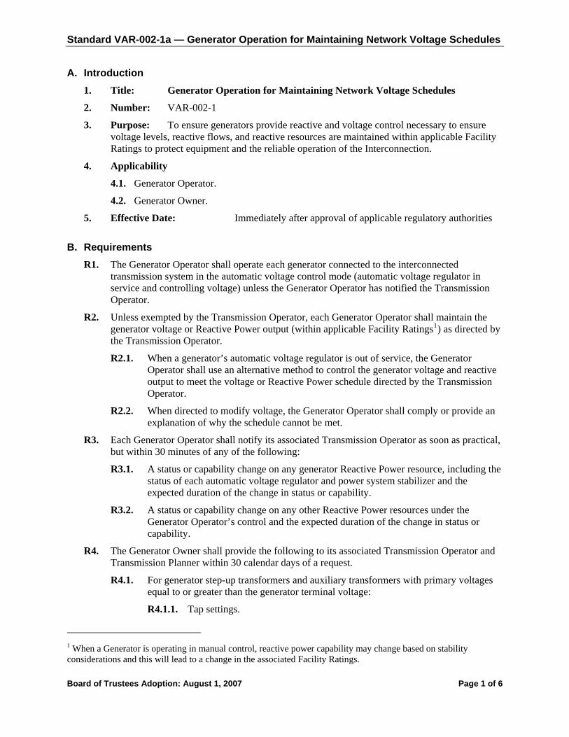
Standard VAR-002-1a — Generator Operation for Maintaining Network Voltage Schedules
A. Introduction 1. Title: Generator Operation for Maintaining Network Voltage Schedules
2. Number: VAR-002-1
3. Purpose: To ensure generators provide reactive and voltage control necessary to ensure voltage levels, reactive flows, and reactive resources are maintained within applicable Facility Ratings to protect equipment and the reliable operation of the Interconnection.
4. Applicability
4.1. Generator Operator.
4.2. Generator Owner.
5. Effective Date: Immediately after approval of applicable regulatory authorities
B. Requirements R1. The Generator Operator shall operate each generator connected to the interconnected
transmission system in the automatic voltage control mode (automatic voltage regulator in service and controlling voltage) unless the Generator Operator has notified the Transmission Operator.
R2. Unless exempted by the Transmission Operator, each Generator Operator shall maintain the generator voltage or Reactive Power output (within applicable Facility Ratings1) as directed by the Transmission Operator.
R2.1. When a generator’s automatic voltage regulator is out of service, the Generator Operator shall use an alternative method to control the generator voltage and reactive output to meet the voltage or Reactive Power schedule directed by the Transmission Operator.
R2.2. When directed to modify voltage, the Generator Operator shall comply or provide an explanation of why the schedule cannot be met.
R3. Each Generator Operator shall notify its associated Transmission Operator as soon as practical, but within 30 minutes of any of the following:
R3.1. A status or capability change on any generator Reactive Power resource, including the status of each automatic voltage regulator and power system stabilizer and the expected duration of the change in status or capability.
R3.2. A status or capability change on any other Reactive Power resources under the Generator Operator’s control and the expected duration of the change in status or capability.
R4. The Generator Owner shall provide the following to its associated Transmission Operator and Transmission Planner within 30 calendar days of a request.
R4.1. For generator step-up transformers and auxiliary transformers with primary voltages equal to or greater than the generator terminal voltage:
R4.1.1. Tap settings.
1 When a Generator is operating in manual control, reactive power capability may change based on stability considerations and this will lead to a change in the associated Facility Ratings.
Board of Trustees Adoption: August 1, 2007 Page 1 of 6

Standard VAR-002-1a — Generator Operation for Maintaining Network Voltage Schedules
R4.1.2. Available fixed tap ranges.
R4.1.3. Impedance data.
R4.1.4. The +/- voltage range with step-change in % for load-tap changing transformers.
R5. After consultation with the Transmission Operator regarding necessary step-up transformer tap changes, the Generator Owner shall ensure that transformer tap positions are changed according to the specifications provided by the Transmission Operator, unless such action would violate safety, an equipment rating, a regulatory requirement, or a statutory requirement.
R5.1. If the Generator Operator can’t comply with the Transmission Operator’s specifications, the Generator Operator shall notify the Transmission Operator and shall provide the technical justification.
C. Measures M1. The Generator Operator shall have evidence to show that it notified its associated Transmission
Operator any time it failed to operate a generator in the automatic voltage control mode as specified in Requirement 1.
M2. The Generator Operator shall have evidence to show that it controlled its generator voltage and reactive output to meet the voltage or Reactive Power schedule provided by its associated Transmission Operator as specified in Requirement 2.
M3. The Generator Operator shall have evidence to show that it responded to the Transmission Operator’s directives as identified in Requirement 2.1 and Requirement 2.2.
M4. The Generator Operator shall have evidence it notified its associated Transmission Operator within 30 minutes of any of the changes identified in Requirement 3.
M5. The Generator Owner shall have evidence it provided its associated Transmission Operator and Transmission Planner with information on its step-up transformers and auxiliary transformers as required in Requirements 4.1.1 through 4.1.4
M6. The Generator Owner shall have evidence that its step-up transformer taps were modified per the Transmission Operator’s documentation as identified in Requirement 5.
M7. The Generator Operator shall have evidence that it notified its associated Transmission Operator when it couldn’t comply with the Transmission Operator’s step-up transformer tap specifications as identified in Requirement 5.1.
D. Compliance 1. Compliance Monitoring Process
1.1. Compliance Monitoring Responsibility
Regional Reliability Organization.
1.2. Compliance Monitoring Period and Reset Time Frame
One calendar year.
1.3. Data Retention
The Generator Operator shall maintain evidence needed for Measure 1 through Measure 5 and Measure 7 for the current and previous calendar years.
The Generator Owner shall keep its latest version of documentation on its step-up and auxiliary transformers. (Measure 6)
Board of Trustees Adoption: August 1, 2007 Page 2 of 6

Standard VAR-002-1a — Generator Operation for Maintaining Network Voltage Schedules
The Compliance Monitor shall retain any audit data for three years.
1.4. Additional Compliance Information
The Generator Owner and Generator Operator shall each demonstrate compliance through self-certification or audit (periodic, as part of targeted monitoring or initiated by complaint or event), as determined by the Compliance Monitor.
2. Levels of Non-Compliance for Generator Operator
2.1. Level 1: There shall be a Level 1 non-compliance if any of the following conditions exist:
2.1.1 One incident of failing to notify the Transmission Operator as identified in , R3.1, R3.2 or R5.1.
2.1.2 One incident of failing to maintain a voltage or reactive power schedule (R2).
2.2. Level 2: There shall be a Level 2 non-compliance if any of the following conditions exist:
2.2.1 More than one but less than five incidents of failing to notify the Transmission as identified in R1, R3.1,R3.2 or R5.1.
2.2.2 More than one but less than five incidents of failing to maintain a voltage or reactive power schedule (R2).
2.3. Level 3: There shall be a Level 3 non-compliance if any of the following conditions exist:
2.3.1 More than five but less than ten incidents of failing to notify the Transmission Operator as identified in R1, R3.1, R3.2 or R5.1.
2.3.2 More than five but less than ten incidents of failing to maintain a voltage or reactive power schedule (R2).
2.4. Level 4: There shall be a Level 4 non-compliance if any of the following conditions exist:
2.4.1 Failed to comply with the Transmission Operator’s directives as identified in R2.
2.4.2 Ten or more incidents of failing to notify the Transmission Operator as identified in R1, R3.1, R3.2 or R5.1.
2.4.3 Ten or more incidents of failing to maintain a voltage or reactive power schedule (R2).
3. Levels of Non-Compliance for Generator Owner:
3.1.1 Level One: Not applicable.
3.1.2 Level Two: Documentation of generator step-up transformers and auxiliary transformers with primary voltages equal to or greater than the generator terminal voltage was missing two of the data types identified in R4.1.1 through R4.1.4.
3.1.3 Level Three: No documentation of generator step-up transformers and auxiliary transformers with primary voltages equal to or greater than the generator terminal voltage
3.1.4 Level Four: Did not ensure generating unit step-up transformer settings were changed in compliance with the specifications provided by the Transmission Operator as identified in R5.
Board of Trustees Adoption: August 1, 2007 Page 3 of 6
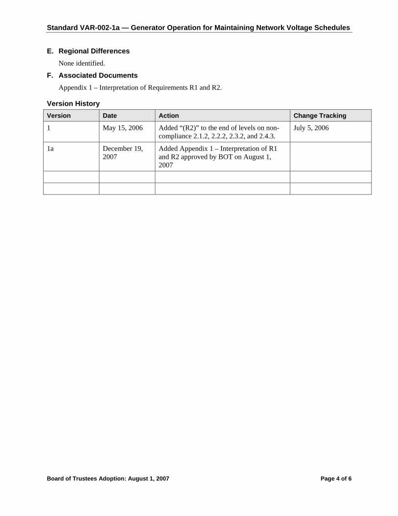
Standard VAR-002-1a — Generator Operation for Maintaining Network Voltage Schedules
E. Regional Differences None identified.
F. Associated Documents Appendix 1 – Interpretation of Requirements R1 and R2.
Version History Version Date Action Change Tracking
1 May 15, 2006 Added “(R2)” to the end of levels on non-compliance 2.1.2, 2.2.2, 2.3.2, and 2.4.3.
July 5, 2006
1a December 19, 2007
Added Appendix 1 – Interpretation of R1 and R2 approved by BOT on August 1, 2007
Board of Trustees Adoption: August 1, 2007 Page 4 of 6

Standard VAR-002-1a — Generator Operation for Maintaining Network Voltage Schedules
Appendix 1
Interpretation of Requirements R1 and R2 Request:
Requirement R1 of Standard VAR-002-1 states that Generation Operators shall operate each generator connected to the interconnected transmission system in the automatic voltage control mode (automatic voltage regulator in service and controlling voltage) unless the Generator Operator has notified the Transmission Operator.
Requirement R2 goes on to state that each Generation Operator shall maintain the generator voltage or Reactive Power output as directed by the Transmission Operator.
The two underlined phrases are the reasons for this interpretation request.
Most generation excitation controls include a device known as the Automatic Voltage Regulator, or AVR. This is the device which is referred to by the R1 requirement above. Most AVR’s have the option of being set in various operating modes, such as constant voltage, constant power factor, and constant Mvar.
In the course of helping members of the WECC insure that they are in full compliance with NERC Reliability Standards, I have discovered both Transmission Operators and Generation Operators who have interpreted this standard to mean that AVR operation in the constant power factor or constant Mvar modes complies with the R1 and R2 requirements cited above. Their rational is as follows:
The AVR is clearly in service because it is operating in one of its operating modes The AVR is clearly controlling voltage because to maintain constant PF or constant Mvar, it
controls the generator terminal voltage R2 clearly gives the Transmission Operator the option of directing the Generation Operator to
maintain a constant reactive power output rather than a constant voltage.
Other parties have interpreted this standard to require operation in the constant voltage mode only. Their rational stems from the belief that the purpose of the VAR-002-1 standard is to insure the automatic delivery of additional reactive to the system whenever a voltage decline begins to occur.
The material impact of misinterpretation of these standards is twofold.
First, misinterpretation may result in reduced reactive response during system disturbances, which in turn may contribute to voltage collapse.
Second, misinterpretation may result in substantial financial penalties imposed on generation operators and transmission operators who believe that they are in full compliance with the standard.
In accordance with the NERC Reliability Standards Development Procedure, I am requesting that a formal interpretation of the VAR-002-1 standard be provided. Two specific questions need to be answered.
First, does AVR operation in the constant PF or constant Mvar modes comply with R1? Second, does R2 give the Transmission Operator the option of directing the Generation Owner to
operate the AVR in the constant Pf or constant Mvar modes rather than the constant voltage mode?
Board of Trustees Adoption: August 1, 2007 Page 5 of 6

Standard VAR-002-1a — Generator Operation for Maintaining Network Voltage Schedules
Interpretation:
1. First, does AVR operation in the constant PF or constant Mvar modes comply with R1?
Interpretation: No, only operation in constant voltage mode meets this requirement. This answer is predicated on the assumption that the generator has the physical equipment that will allow such operation and that the Transmission Operator has not directed the generator to run in a mode other than constant voltage.
2. Second, does R2 give the Transmission Operator the option of directing the Generation Owner (sic) to operate the AVR in the constant Pf or constant Mvar modes rather than the constant voltage mode?
Interpretation: Yes, if the Transmission Operator specifically directs a Generator Operator to operate the AVR in a mode other than constant voltage mode, then that directed mode of AVR operation is allowed.
Board of Trustees Adoption: August 1, 2007 Page 6 of 6

Standard VAR-002-1a — Generator Operation for Maintaining Network Voltage Schedules
Board of Trustees Adoption: August 1, 2007 Page 1 of 6
A. Introduction 1. Title: Generator Operation for Maintaining Network Voltage Schedules
2. Number: VAR-002-1
3. Purpose: To ensure generators provide reactive and voltage control necessary to ensure voltage levels, reactive flows, and reactive resources are maintained within applicable Facility Ratings to protect equipment and the reliable operation of the Interconnection.
4. Applicability
4.1. Generator Operator.
4.2. Generator Owner.
5. Effective Date: Immediately after approval of applicable regulatory authorities
B. Requirements R1. The Generator Operator shall operate each generator connected to the interconnected
transmission system in the automatic voltage control mode (automatic voltage regulator in service and controlling voltage) unless the Generator Operator has notified the Transmission Operator.
R2. Unless exempted by the Transmission Operator, each Generator Operator shall maintain the generator voltage or Reactive Power output (within applicable Facility Ratings1) as directed by the Transmission Operator.
R2.1. When a generator’s automatic voltage regulator is out of service, the Generator Operator shall use an alternative method to control the generator voltage and reactive output to meet the voltage or Reactive Power schedule directed by the Transmission Operator.
R2.2. When directed to modify voltage, the Generator Operator shall comply or provide an explanation of why the schedule cannot be met.
R3. Each Generator Operator shall notify its associated Transmission Operator as soon as practical, but within 30 minutes of any of the following:
R3.1. A status or capability change on any generator Reactive Power resource, including the status of each automatic voltage regulator and power system stabilizer and the expected duration of the change in status or capability.
R3.2. A status or capability change on any other Reactive Power resources under the Generator Operator’s control and the expected duration of the change in status or capability.
R4. The Generator Owner shall provide the following to its associated Transmission Operator and Transmission Planner within 30 calendar days of a request.
R4.1. For generator step-up transformers and auxiliary transformers with primary voltages equal to or greater than the generator terminal voltage:
R4.1.1. Tap settings.
1 When a Generator is operating in manual control, reactive power capability may change based on stability considerations and this will lead to a change in the associated Facility Ratings.
Deleted: Six months after effective date of VAR-001-1.
Deleted: 2
Deleted: 2006
Deleted: Effective Date: Six months after effective date of VAR-001-1.
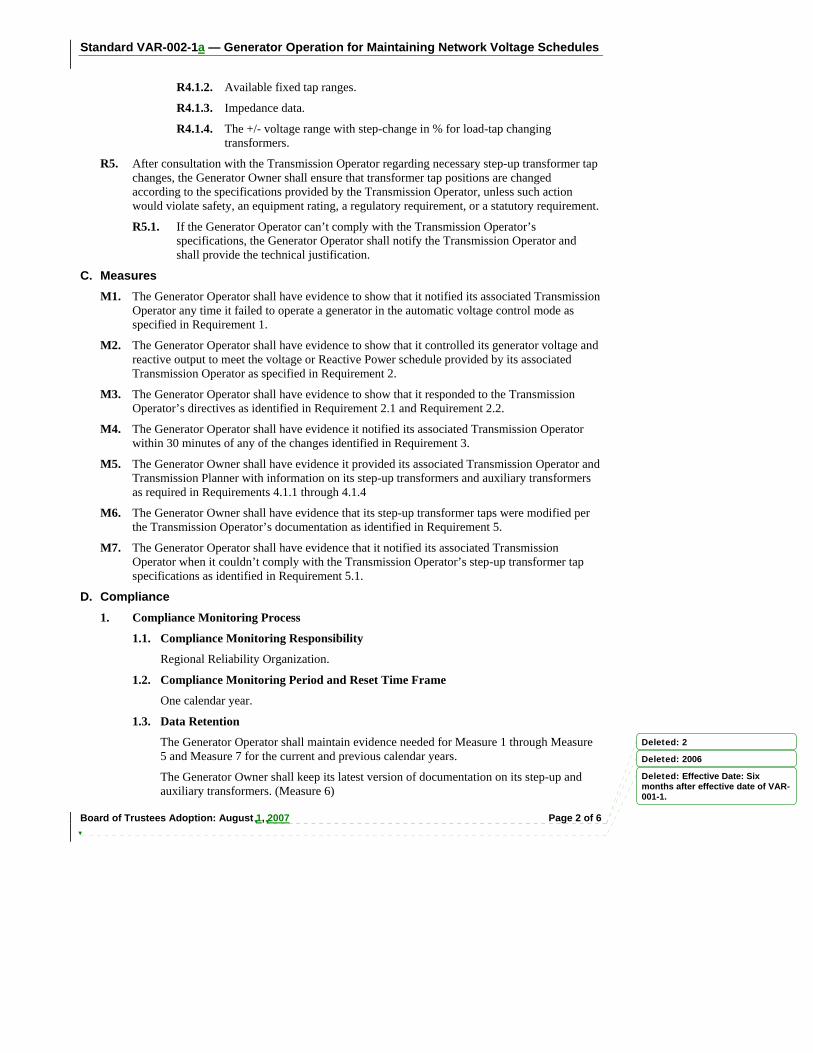
Standard VAR-002-1a — Generator Operation for Maintaining Network Voltage Schedules
Board of Trustees Adoption: August 1, 2007 Page 2 of 6
R4.1.2. Available fixed tap ranges.
R4.1.3. Impedance data.
R4.1.4. The +/- voltage range with step-change in % for load-tap changing transformers.
R5. After consultation with the Transmission Operator regarding necessary step-up transformer tap changes, the Generator Owner shall ensure that transformer tap positions are changed according to the specifications provided by the Transmission Operator, unless such action would violate safety, an equipment rating, a regulatory requirement, or a statutory requirement.
R5.1. If the Generator Operator can’t comply with the Transmission Operator’s specifications, the Generator Operator shall notify the Transmission Operator and shall provide the technical justification.
C. Measures M1. The Generator Operator shall have evidence to show that it notified its associated Transmission
Operator any time it failed to operate a generator in the automatic voltage control mode as specified in Requirement 1.
M2. The Generator Operator shall have evidence to show that it controlled its generator voltage and reactive output to meet the voltage or Reactive Power schedule provided by its associated Transmission Operator as specified in Requirement 2.
M3. The Generator Operator shall have evidence to show that it responded to the Transmission Operator’s directives as identified in Requirement 2.1 and Requirement 2.2.
M4. The Generator Operator shall have evidence it notified its associated Transmission Operator within 30 minutes of any of the changes identified in Requirement 3.
M5. The Generator Owner shall have evidence it provided its associated Transmission Operator and Transmission Planner with information on its step-up transformers and auxiliary transformers as required in Requirements 4.1.1 through 4.1.4
M6. The Generator Owner shall have evidence that its step-up transformer taps were modified per the Transmission Operator’s documentation as identified in Requirement 5.
M7. The Generator Operator shall have evidence that it notified its associated Transmission Operator when it couldn’t comply with the Transmission Operator’s step-up transformer tap specifications as identified in Requirement 5.1.
D. Compliance 1. Compliance Monitoring Process
1.1. Compliance Monitoring Responsibility
Regional Reliability Organization.
1.2. Compliance Monitoring Period and Reset Time Frame
One calendar year.
1.3. Data Retention
The Generator Operator shall maintain evidence needed for Measure 1 through Measure 5 and Measure 7 for the current and previous calendar years.
The Generator Owner shall keep its latest version of documentation on its step-up and auxiliary transformers. (Measure 6)
Deleted: 2
Deleted: 2006
Deleted: Effective Date: Six months after effective date of VAR-001-1.
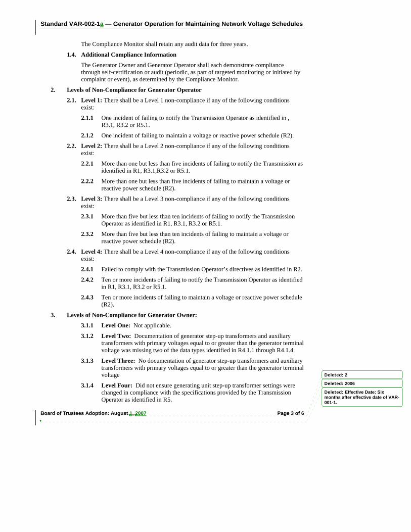
Standard VAR-002-1a — Generator Operation for Maintaining Network Voltage Schedules
Board of Trustees Adoption: August 1, 2007 Page 3 of 6
The Compliance Monitor shall retain any audit data for three years.
1.4. Additional Compliance Information
The Generator Owner and Generator Operator shall each demonstrate compliance through self-certification or audit (periodic, as part of targeted monitoring or initiated by complaint or event), as determined by the Compliance Monitor.
2. Levels of Non-Compliance for Generator Operator
2.1. Level 1: There shall be a Level 1 non-compliance if any of the following conditions exist:
2.1.1 One incident of failing to notify the Transmission Operator as identified in , R3.1, R3.2 or R5.1.
2.1.2 One incident of failing to maintain a voltage or reactive power schedule (R2).
2.2. Level 2: There shall be a Level 2 non-compliance if any of the following conditions exist:
2.2.1 More than one but less than five incidents of failing to notify the Transmission as identified in R1, R3.1,R3.2 or R5.1.
2.2.2 More than one but less than five incidents of failing to maintain a voltage or reactive power schedule (R2).
2.3. Level 3: There shall be a Level 3 non-compliance if any of the following conditions exist:
2.3.1 More than five but less than ten incidents of failing to notify the Transmission Operator as identified in R1, R3.1, R3.2 or R5.1.
2.3.2 More than five but less than ten incidents of failing to maintain a voltage or reactive power schedule (R2).
2.4. Level 4: There shall be a Level 4 non-compliance if any of the following conditions exist:
2.4.1 Failed to comply with the Transmission Operator’s directives as identified in R2.
2.4.2 Ten or more incidents of failing to notify the Transmission Operator as identified in R1, R3.1, R3.2 or R5.1.
2.4.3 Ten or more incidents of failing to maintain a voltage or reactive power schedule (R2).
3. Levels of Non-Compliance for Generator Owner:
3.1.1 Level One: Not applicable.
3.1.2 Level Two: Documentation of generator step-up transformers and auxiliary transformers with primary voltages equal to or greater than the generator terminal voltage was missing two of the data types identified in R4.1.1 through R4.1.4.
3.1.3 Level Three: No documentation of generator step-up transformers and auxiliary transformers with primary voltages equal to or greater than the generator terminal voltage
3.1.4 Level Four: Did not ensure generating unit step-up transformer settings were changed in compliance with the specifications provided by the Transmission Operator as identified in R5.
Deleted: 2
Deleted: 2006
Deleted: Effective Date: Six months after effective date of VAR-001-1.
Standard VAR-002-1a — Generator Operation for Maintaining Network Voltage Schedules
Board of Trustees Adoption: August 1, 2007 Page 4 of 6
E. Regional Differences None identified.
F. Associated Documents Appendix 1 – Interpretation of Requirements R1 and R2.
Version History Version Date Action Change Tracking
1 May 15, 2006 Added “(R2)” to the end of levels on non-compliance 2.1.2, 2.2.2, 2.3.2, and 2.4.3.
July 5, 2006
1a December 19, 2007
Added Appendix 1 – Interpretation of R1 and R2 approved by BOT on August 1, 2007
Deleted: 2
Deleted: 2006
Deleted: Effective Date: Six months after effective date of VAR-001-1.
Formatted: Bullets and Numbering
Formatted: Font: (Default) TimesNew Roman, 11 pt, Not Bold
Formatted: Font: (Default) TimesNew Roman, 11 pt, Not Bold
Formatted: Font: (Default) TimesNew Roman, 11 pt, Not Bold
Formatted: Font: (Default) TimesNew Roman, 11 pt, Not Bold
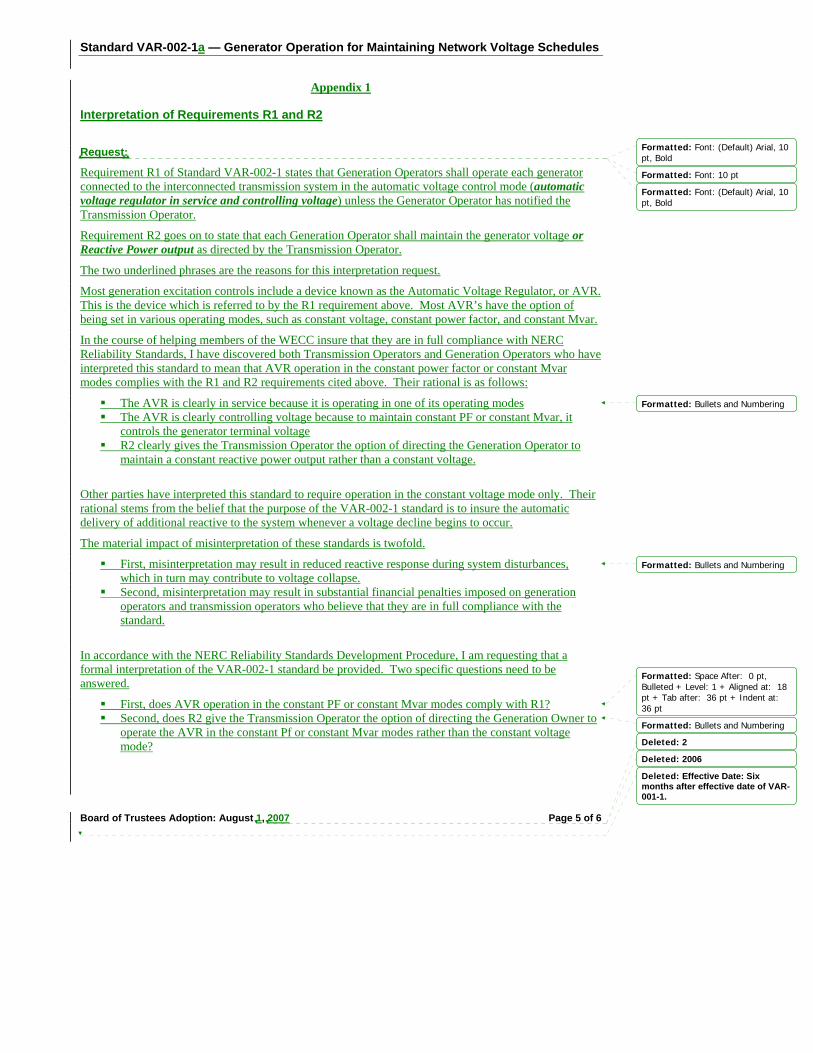
Standard VAR-002-1a — Generator Operation for Maintaining Network Voltage Schedules
Board of Trustees Adoption: August 1, 2007 Page 5 of 6
Appendix 1
Interpretation of Requirements R1 and R2 Request:
Requirement R1 of Standard VAR-002-1 states that Generation Operators shall operate each generator connected to the interconnected transmission system in the automatic voltage control mode (automatic voltage regulator in service and controlling voltage) unless the Generator Operator has notified the Transmission Operator.
Requirement R2 goes on to state that each Generation Operator shall maintain the generator voltage or Reactive Power output as directed by the Transmission Operator.
The two underlined phrases are the reasons for this interpretation request.
Most generation excitation controls include a device known as the Automatic Voltage Regulator, or AVR. This is the device which is referred to by the R1 requirement above. Most AVR’s have the option of being set in various operating modes, such as constant voltage, constant power factor, and constant Mvar.
In the course of helping members of the WECC insure that they are in full compliance with NERC Reliability Standards, I have discovered both Transmission Operators and Generation Operators who have interpreted this standard to mean that AVR operation in the constant power factor or constant Mvar modes complies with the R1 and R2 requirements cited above. Their rational is as follows:
The AVR is clearly in service because it is operating in one of its operating modes The AVR is clearly controlling voltage because to maintain constant PF or constant Mvar, it
controls the generator terminal voltage R2 clearly gives the Transmission Operator the option of directing the Generation Operator to
maintain a constant reactive power output rather than a constant voltage.
Other parties have interpreted this standard to require operation in the constant voltage mode only. Their rational stems from the belief that the purpose of the VAR-002-1 standard is to insure the automatic delivery of additional reactive to the system whenever a voltage decline begins to occur.
The material impact of misinterpretation of these standards is twofold.
First, misinterpretation may result in reduced reactive response during system disturbances, which in turn may contribute to voltage collapse.
Second, misinterpretation may result in substantial financial penalties imposed on generation operators and transmission operators who believe that they are in full compliance with the standard.
In accordance with the NERC Reliability Standards Development Procedure, I am requesting that a formal interpretation of the VAR-002-1 standard be provided. Two specific questions need to be answered.
First, does AVR operation in the constant PF or constant Mvar modes comply with R1? Second, does R2 give the Transmission Operator the option of directing the Generation Owner to
operate the AVR in the constant Pf or constant Mvar modes rather than the constant voltage mode?
Deleted: 2
Deleted: 2006
Deleted: Effective Date: Six months after effective date of VAR-001-1.
Formatted: Font: (Default) Arial, 10pt, Bold
Formatted: Font: (Default) Arial, 10pt, Bold
Formatted: Font: 10 pt
Formatted: Bullets and Numbering
Formatted: Bullets and Numbering
Formatted: Bullets and Numbering
Formatted: Space After: 0 pt,Bulleted + Level: 1 + Aligned at: 18pt + Tab after: 36 pt + Indent at: 36 pt

Standard VAR-002-1a — Generator Operation for Maintaining Network Voltage Schedules
Board of Trustees Adoption: August 1, 2007 Page 6 of 6
Interpretation:
1. First, does AVR operation in the constant PF or constant Mvar modes comply with R1?
Interpretation: No, only operation in constant voltage mode meets this requirement. This answer is predicated on the assumption that the generator has the physical equipment that will allow such operation and that the Transmission Operator has not directed the generator to run in a mode other than constant voltage.
2. Second, does R2 give the Transmission Operator the option of directing the Generation Owner (sic) to operate the AVR in the constant Pf or constant Mvar modes rather than the constant voltage mode?
Interpretation: Yes, if the Transmission Operator specifically directs a Generator Operator to operate the AVR in a mode other than constant voltage mode, then that directed mode of AVR operation is allowed.
Deleted: 2
Deleted: 2006
Deleted: Effective Date: Six months after effective date of VAR-001-1.
Formatted: Font: 11 pt, Bold
Formatted: Indent: Left: 18 pt
Formatted: Indent: Left: 0 pt,Tabs: 18 pt, List tab + Not at 36 pt
Formatted: Bullets and Numbering
Formatted: Indent: Left: 0 pt
Formatted: Indent: Left: 0 pt
Formatted: Indent: Left: 18 pt
Formatted: Font: 11 pt
Formatted: Indent: Left: 0 pt,Tabs: 18 pt, List tab + Not at 36 pt
Formatted: Bullets and Numbering

Exhibit B-3
Record of Development of Formal Interpretations for VAR-002-1, Requirements R1 and R2

Regions | Committees | Meetings | Search | Site Map | Contact Us | Home
Reliability Standards
Interpretation - VAR-002 - Generator Operation for Maintaining Network
Voltage Schedules
Registered Ballot Body | Reliability Standards Home Page
Status The interpretation for standard VAR-002-1, Requirements 1 and 2 was approved by stakeholders and is pending regulatory filing.
Purpose/Industry Need Mariner Consulting Services, Inc., requested a formal interpretation to VAR-002-1 — Generator Operation for Maintaining Network Voltage Schedules, Requirements 1 and 2. Members of the Phase III–IV Standards Drafting Team, working with NERC staff, developed the interpretation.
Proposed StandardSupporting Documents Comment Period
Comments Received
Response to Comments
Announcement (6)
Request for Interpretation VAR-002-1,
Requirements 1 and 2 - Generator Operation for
Maintaining Network Voltage Schedules Posted for 10-day Recirculation Ballot
Window June 20 through June
29, 2007
VAR-002-1 Interpretation (Same as 1)
06/30/07 - 06/29/07
10-day Recirculation Ballot Window
(closed)
Ballot Results (7)
Announcement
Request for Interpretation VAR-002-1,
Requirements 1 and 2 - Generator Operation for
Maintaining Network Voltage Schedules
04/17/07 - 04/26/07
10-day Initial Ballot Window Closed
Ballot Results (4)
Consideration of Comments (5)

Posted for 10-day Initial Ballot Window April 17 through April
26, 2007
VAR-002-1 Interpretation (Same as 1)
Announcement (3)
Request for Interpretation VAR-002-1,
Requirements 1 and 2 - Generator Operation for
Maintaining Network Voltage Schedules Posted for 30-day Pre-ballot Review March 15 through
April 13, 2007
VAR-002-1 Interpretation (1)
Mariner Consulting
Services, Inc.
Request for Interpretation
(2)
VAR-002-1, Requirements
1 and 2
03/15/07 - 04/16/06
30-day Pre-ballot Review
To download a file click on the file using your right mouse button, then save it to your computer in a directory of your choice.
Documents in the PDF format require use of the Adobe Reader® software. Free Adobe Reader® software allows anyone view and print Adobe Portable Document Format (PDF) files. For more information download the Adobe Reader User Guide.
All comments should be forwarded to [email protected].
Questions? Contact Barbara Bogenrief - [email protected] or 609-452-8060.

- 1 -
Request for Interpretation of NERC Standard VAR-002-1 Dated January 24, 2007 John H. Stout Mariner Consulting Services, Inc. 1303 Lake Way Drive Taylor Lake Village, Texas 77586 Requirement R1 of Standard VAR-002-1 states that Generation Operators shall operate each generator connected to the interconnected transmission system in the automatic voltage control mode (automatic voltage regulator in service and controlling voltage) unless the Generator Operator has notified the Transmission Operator. Requirement R2 goes on to state that each Generation Operator shall maintain the generator voltage or Reactive Power output as directed by the Transmission Operator. The two underlined phrases are the reasons for this interpretation request. Most generation excitation controls include a device known as the Automatic Voltage Regulator, or AVR. This is the device which is referred to by the R1 requirement above. Most AVR’s have the option of being set in various operating modes, such as constant voltage, constant power factor, and constant Mvar. In the course of helping members of the WECC insure that they are in full compliance with NERC Reliability Standards, I have discovered both Transmission Operators and Generation Operators who have interpreted this standard to mean that AVR operation in the constant power factor or constant Mvar modes complies with the R1 and R2 requirements cited above. Their rational is as follows:
The AVR is clearly in service because it is operating in one of its operating modes The AVR is clearly controlling voltage because to maintain constant PF or constant Mvar, it
controls the generator terminal voltage R2 clearly gives the Transmission Operator the option of directing the Generation Operator
to maintain a constant reactive power output rather than a constant voltage. Other parties have interpreted this standard to require operation in the constant voltage mode only. Their rational stems from the belief that the purpose of the VAR-002-1 standard is to insure the automatic delivery of additional reactive to the system whenever a voltage decline begins to occur. The material impact of misinterpretation of these standards is twofold.
First, misinterpretation may result in reduced reactive response during system disturbances, which in turn may contribute to voltage collapse.
Second, misinterpretation may result in substantial financial penalties imposed on generation operators and transmission operators who believe that they are in full compliance with the standard.
In accordance with the NERC Reliability Standards Development Procedure, I am requesting that a formal interpretation of the VAR-002-1 standard be provided. Two specific questions need to be answered.

Request for Interpretation of NERC Standard VAR-002-1
- 2 -
First, does AVR operation in the constant PF or constant Mvar modes comply with R1? Second, does R2 give the Transmission Operator the option of directing the Generation
Owner to operate the AVR in the constant Pf or constant Mvar modes rather than the constant voltage mode?
Interpretation of NERC Standard VAR-002-1 Prepared by Phase 3&4 Standard Drafting Team Members Dated March 5, 2007 In response to February 2007 request from John H. Stout Mariner Consulting Services, Inc. 1303 Lake Way Drive Taylor Lake Village, Texas 77586 Questions and Answers The answers to the two questions posed by Mr. John H. Stout are:
1. Question: First, does AVR operation in the constant PF or constant Mvar modes comply with R1?
Answer: No, only operation in constant voltage mode meets this requirement. This answer is predicated on the assumption that the generator has the physical equipment that will allow such operation and that the Transmission Operator has not directed the generator to run in a mode other than constant voltage.
2. Question: Second, does R2 give the Transmission Operator the option of directing the Generation Owner (sic) to operate the AVR in the constant Pf or constant Mvar modes rather than the constant voltage mode?
Answer: Yes, if the Transmission Operator specifically directs a Generator Operator to operate the AVR in a mode other than constant voltage mode, then that directed mode of AVR operation is allowed.
Background and Discussion Requirement R1 of Standard VAR-002-1 states that Generation Operators shall operate each generator connected to the interconnected transmission system in the automatic voltage control mode (automatic voltage regulator in service and controlling voltage) unless the Generator Operator has notified the Transmission Operator. Requirement R1 clearly states controlling voltage. This can only be accomplished by using the automatic voltage control mode. Using the Power Factor (PF) or constant MVAR control is not a true method to control voltage even though they may have some effect on voltage. This is the baseline mode of operation that is clearly conditioned by “unless the Generator Operator has notified the Transmission Operator”. The following Requirement R2 introduces the possibility of an exemption to this baseline mode of operation discussed below.

Request for Interpretation of NERC Standard VAR-002-1
- 3 -
The above interpretation is further reinforced by reviewing the origin of the requirement. The current Requirement R1 is an evolution of the words in the associated source document, namely NERC Planning Standards Compliance Template for III.C.M1, “Operation of all synchronous generators in the automatic voltage control mode”. As stated in the original III.C.S1 Standard: “All synchronous generators connected to the interconnected transmission systems shall be operated with their excitation system in the automatic voltage control mode (automatic voltage regulator in service and controlling voltage) unless approved otherwise by the transmission system operator.” Requirement R2 of Standard VAR-002-1 goes on to state that “Unless exempted by the Transmission Operator, each Generator Operator shall maintain the generator voltage or Reactive Power output (within applicable Facility Ratings) as directed by the Transmission Operator.” The purpose of this requirement is to give the Transmission Operator the ability to direct the Generator Operator to use another mode of operation. This ability may be necessary based on the Transmission Operator’s system studies and/or knowledge of system conditions. This ability also gives the Transmission Operator the latitude to work with the Generator Operator who has a generating unit that lacks the physical equipment to be able to run in the automatic voltage control mode or has contractual requirements to operate in a certain manner.
Both Requirements R1 and R2 in VAR-002-1 were worded such that they coordinate with Requirement R4 in VAR-001-1:
“Each Transmission Operator shall specify a voltage or Reactive Power schedule at the interconnection between the generator facility and the Transmission Owner's facilities to be maintained by each generator. The Transmission Operator shall provide the voltage or Reactive Power schedule to the associated Generator Operator and direct the Generator Operator to comply with the schedule in automatic voltage control mode (AVR in service and controlling voltage). “
Again this Requirement R4 reflects that the baseline mode of operation is to use the automatic voltage control mode with the option for the Transmission Operator to specify other modes of operation as dictated by system studies and needs to maintain system reliability.

Mariner Consulting Services, Inc. John H. Stout [email protected] 1303 Lake Way Drive Taylor Lake Village, Texas 77586 713-252-0535 January 24, 2007 Maureen E. Long Standards Process Manager North American Electric Reliability Council Princeton Forrestal Village 116-390 Village Boulevard Princeton, New Jersey 08540-5721 Request for Interpretation of NERC Standard VAR-002-1 Requirement R1 of Standard VAR-002-1 states that Generation Operators shall operate each generator connected to the interconnected transmission system in the automatic voltage control mode (automatic voltage regulator in service and controlling voltage) unless the Generator Operator has notified the Transmission Operator. Requirement R2 goes on to state that each Generation Operator shall maintain the generator voltage or Reactive Power output as directed by the Transmission Operator. The two underlined phrases are the reasons for this interpretation request. Most generation excitation controls include a device known as the Automatic Voltage Regulator, or AVR. This is the device which is referred to by the R1 requirement above. Most AVR’s have the option of being set in various operating modes, such as constant voltage, constant power factor, and constant Mvar. In the course of helping members of the WECC insure that they are in full compliance with NERC Reliability Standards, I have discovered both Transmission Operators and Generation Operators who have interpreted this standard to mean that AVR operation in the constant power factor or constant Mvar modes complies with the R1 and R2 requirements cited above. Their rational is as follows…
The AVR is clearly in service because it is operating in one of its operating modes The AVR is clearly controlling voltage because to maintain constant PF or constant
Mvar, it controls the generator terminal voltage R2 clearly gives the Transmission Operator the option of directing the Generation
Operator to maintain a constant reactive power output rather than a constant voltage. Other parties have interpreted this standard to require operation in the constant voltage mode only. Their rational stems from the belief that the purpose of the VAR-002-1 standard is to insure the automatic delivery of additional reactive to the system whenever a voltage decline begins to occur.

The material impact of misinterpretation of these standards is twofold.
First, misinterpretation may result in reduced reactive response during system disturbances, which in turn may contribute to voltage collapse.
Second, misinterpretation may result in substantial financial penalties imposed on generation operators and transmission operators who believe that they are in full compliance with the standard.
In accordance with the NERC Reliability Standards Development Procedure, I am requesting that a formal interpretation of the VAR-002-1 standard be provided. Two specific questions need to be answered.
First, does AVR operation in the constant PF or constant Mvar modes comply with R1? Second, does R2 give the Transmission Operator the option of directing the Generation
Owner to operate the AVR in the constant Pf or constant Mvar modes rather than the constant voltage mode?
Please let me know if any additional information is needed in order to provide the requested interpretation. Thank you for addressing this request,
John Stout
Maureen E. Long Standards Process Manager
March 15, 2007
TO: REGISTERED BALLOT BODY Ladies and Gentlemen:
Announcement:
Pre-ballot Window and Ballot Pool Open on March 15, 2007
The Standards Committee announces the following standards actions:
Pre-ballot Window and Ballot Pool Open on March 15, 2007 for Interpretation of VAR-002-1, Requirements 1 and 2
Mariner Consulting Services, Inc., requested a formal interpretation to VAR-002-1 — Generator Operation for Maintaining Network Voltage Schedules, Requirements 1 and 2. Members of the Phase III–IV Standards Drafting Team, working with NERC staff, developed the interpretation.
VAR-002-1, Requirements 1 and 2 states: R1. The Generator Operator shall operate each generator connected to the interconnected
transmission system in the automatic voltage control mode (automatic voltage regulator in service and controlling voltage) unless the Generator Operator has notified the Transmission Operator.
R2. Unless exempted by the Transmission Operator, each Generator Operator shall maintain the generator voltage or Reactive Power output (within applicable Facility Ratings1) as directed by the Transmission Operator.
R2.1. When a generator’s automatic voltage regulator is out of service, the Generator Operator shall use an alternative method to control the generator voltage and reactive output to meet the voltage or Reactive Power schedule directed by the Transmission Operator.
R2.2. When directed to modify voltage, the Generator Operator shall comply or provide an explanation of why the schedule cannot be met.
Two specific questions need to be answered. First, does AVR operation in the constant PF or constant Mvar modes comply with R1?
Answer: No, only operation in constant voltage mode meets this requirement. This answer is predicated on the assumption that the generator has the physical equipment that will allow such operation and that the Transmission Operator has not directed the generator to run in a mode other than constant voltage.
Second, does R2 give the Transmission Operator the option of directing the Generation
Owner to operate the AVR in the constant Pf or constant Mvar modes rather than the constant voltage mode?
116-390 Village Boulevard, Princeton, New Jersey 08540-5721
Phone: 609.452.8060 ▪ Fax: 609.452.9550 ▪ www.nerc.com
1 When a Generator is operating in manual control, reactive power capability may change based on stability considerations and this will lead to a change in the associated Facility Ratings.

REGISTERED BALLOT BODY March 15, 2007 Page Two
Yes, if the Transmission Operator specifically directs a Generator Operator to operate the AVR in a mode other than constant voltage mode, then that directed mode of AVR operation is allowed.
In accordance with the Reliability Standards Development Procedure, the interpretation must be posted for a 30-day, pre-ballot review, and then balloted. There is no public comment period for an interpretation. Balloting will be conducted following the same method used for balloting standards. If the interpretation is approved by its ballot pool, then the interpretation will be appended to the standard and will become effective when adopted by the NERC Board of Trustees and approved by the applicable regulatory authorities. The interpretation will remain appended to the standard until the standard is revised through the normal standards development process. When the standard is revised, the clarifications provided by the interpretation will be incorporated into the revised standard. The Interpretation of VAR-002-1, Requirements 1 and 2 is posted for a 30-day, pre-ballot review. A ballot pool to vote on the interpretation has been formed and will remain open through 8 a.m. (EDT) Friday, April 16, 2007. During the pre-ballot window, members of the ballot pool may communicate with one another by using their “ballot pool list server2.” The list server for this ballot pool is called: [email protected] Before joining the ballot pool, please make sure that you will be available during the ballot window to cast your ballot. The initial ballot for the interpretation to VAR-002-1 will be conducted from 8 a.m. (EDT) on Friday, April 16 through 8 p.m. (EDT) Monday, April 26, 2006. Standards Development Process The Reliability Standards Development Procedure contains all the procedures governing the standards development process. The success of the NERC standards development process depends on stakeholder participation. We extend our thanks to all those who participate. If you have any questions, please contact me at 813-468-5998 or [email protected].
Sincerely,
Maureen E. Long cc: Registered Ballot Body Registered Users Standards Mailing List NERC Roster
2 For assistance in using a list server, contact Barbara Bogenrief at 609-452-8060.

Regions | Committees | Meetings | Search | Site Map | Contact Us
Reliability Standards
User Name
Password
Log in
Register Reliability Standards HomeAnnouncements BOT Approved StandardsRegulatory Approved StandardsStandards Under DevelopmentBallot PoolsCurrent BallotsBallot ResultsRegistered Ballot BodyProxy VotersRegistration InstructionsRegional Reliability Standards NERC Home
Ballot Results
Ballot Name: Interpretation Request for Standard VAR-002-1_in
Ballot Period: 4/17/2007 - 4/26/2007
Ballot Type: Initial
Total # Votes: 187
Total Ballot Pool: 224
Quorum: 83.48 % The Quorum has been reached
Weighted Segment Vote:
97.23 %
Ballot Results: The standard will proceed to recirculation ballot.
Summary of Ballot Results
Segment Ballot Pool
Segment Weight
Affirmative Negative Abstain
No Vote
# Votes Fraction
# Votes Fraction
# Votes
1 - Segment 1. 67 1 53 0.964 2 0.036 0 122 - Segment 2. 9 0.7 7 0.7 0 0 0 23 - Segment 3. 53 1 41 0.953 2 0.047 1 94 - Segment 4. 10 0.9 9 0.9 0 0 0 15 - Segment 5. 43 1 32 0.889 4 0.111 0 76 - Segment 6. 25 1 21 1 0 0 1 37 - Segment 7. 0 0 0 0 0 0 0 08 - Segment 8. 4 0.4 4 0.4 0 0 0 09 - Segment 9. 5 0.5 5 0.5 0 0 0 010 - Segment 10. 8 0.5 5 0.5 0 0 0 3
Totals 224 7 177 6.806 8 0.194 2 37
Individual Ballot Pool Results
Segment Organization Member Ballot Comments
1AEP Service Corp. -- Transmission System AEP
Scott P. Moore Affirmative
1 Allegheny Power Rodney Phillips Affirmative 1 Alliant Energy Kenneth Goldsmith Affirmative 1 AltaLink Management Ltd. Rick Spyker Affirmative 1 Ameren Services Company Kirit S Shah Affirmative 1 American Public Power Association E. Nick Henery Affirmative 1 Avista Corp. Scott Kinney Affirmative 1 Baltimore Gas & Electric Company John J. Moraski Negative View 1 Bonneville Power Administration Donald S. Watkins Affirmative 1 CenterPoint Energy Paul Rocha Affirmative 1 Central Maine Power Company David Mark Conroy
Page 1 of 6Untitled Page
4/27/2007https://standards.nerc.net/BallotResults.aspx?BallotGUID=f23eeb20-ecad-444e-be78-bc85...

1Consolidated Edison Co. of New York
Edwin E. Thompson PE Affirmative
1 Dairyland Power Coop. Robert W. Roddy Affirmative 1 Dominion Virginia Power William L. Thompson1 Duke Energy Doug Hils Affirmative 1 East Kentucky Power Coop. George S. Carruba Affirmative 1 Empire District Electric Co. Ralph Frederick Meyer Affirmative 1 Entergy Corporation George R. Bartlett Affirmative 1 Exelon Energy John J. Blazekovich Affirmative 1 FirstEnergy Energy Delivery Robert Martinko Affirmative
1Florida Keys Electric Cooperative Assoc.
Dennis Minton
1 Florida Power & Light Co. C. Martin Mennes Affirmative 1 Great River Energy Gordon Pietsch Affirmative
1Hoosier Energy Rural Electric Cooperative, Inc.
Damon Holladay Affirmative
1 Hydro One Networks, Inc. Ajay Garg Affirmative 1 Hydro-Quebec TransEnergie Julien Gagnon Affirmative 1 ITC Transmission Brian F. Thumm1 JEA Ted E. Hobson Affirmative 1 Kansas City Power & Light Co. Jim Useldinger1 Keyspan LIPA Richard J. Bolbrock Affirmative 1 Manitoba Hydro Robert G. Coish Affirmative 1 Minnesota Power, Inc. Carol Gerou Affirmative 1 Montana-Dakota Utilities Co. Henry Ford
1Municipal Electric Authority of Georgia
Jerry J Tang Affirmative
1 National Grid USA Herbert Schrayshuen Affirmative
1New Brunswick Power Transmission Corporation
Wayne N. Snowdon Affirmative
1 New York Power Authority Ralph Rufrano1 Northeast Utilities David H Boguslawski1 Northern Indiana Public Service Co. Joseph Dobes Affirmative 1 Ohio Valley Electric Corp. Robert Mattey Affirmative 1 Oklahoma Gas and Electric Co. Melvin H. Perkins1 Oncor Charles W. Jenkins Affirmative 1 Otter Tail Power Company Lawrence R. Larson Affirmative 1 PacifiCorp Robert Williams1 Potomac Electric Power Co. Richard J. Kafka Affirmative 1 PP&L, Inc. Ray Mammarella Affirmative 1 Progress Energy Carolinas Verne B. Ingersoll Affirmative
1Public Service Company of New Mexico
Keith Nix Affirmative
1 Public Service Electric and Gas Co. Colin Loxley Affirmative 1 Sacramento Municipal Utility District Dilip Mahendra Affirmative 1 Salt River Project Robert Kondziolka Affirmative 1 San Diego Gas & Electric Linda Brown Negative 1 Santee Cooper Terry L. Blackwell Affirmative 1 SaskPower Wayne Guttormson Affirmative 1 Seattle City Light Christopher M. Turner Affirmative 1 Sierra Pacific Power Co. Richard Salgo Affirmative 1 Southern California Edison Co. Dana Cabbell Affirmative
1 Southern Company Services, Inc.Horace Stephen Williamson
Affirmative
1 Southern Illinois Power Coop. William G. Hutchison Affirmative 1 Southwest Transmission Coop., Inc. Alan H. Wilkinson Affirmative 1 Southwestern Power Administration Stanley Mason Affirmative 1 Tampa Electric Co. Paul Michael Davis
Page 2 of 6Untitled Page
4/27/2007https://standards.nerc.net/BallotResults.aspx?BallotGUID=f23eeb20-ecad-444e-be78-bc85...

1 Tri-State G & T Association Inc. Bruce A Sembrick1 Tucson Electric Power Co. Ronald P. Belval Affirmative 1 Westar Energy Allen Klassen Affirmative
1Western Area Power Administration - CM WACM
Mark E. Fidrych Affirmative
1 Xcel Energy, Inc. Gregory L. Pieper Affirmative 2 Alberta Electric System Operator Anita Lee Affirmative
2British Columbia Transmission Corporation
Phil Park
2 California ISO David Hawkins Affirmative
2Independent Electricity System Operator
Don Tench Affirmative
2 ISO New England, Inc. Kathleen Goodman2 Midwest ISO, Inc. Terry Bilke Affirmative 2 New Brunswick System Operator Alden Briggs Affirmative
2New York Independent System Operator
Gregory Campoli Affirmative
2 PJM Interconnection, L.L.C. Tom Bowe Affirmative 3 Alabama Power Company Robin Hurst Affirmative 3 Allegheny Power Bob Reeping Affirmative 3 Arizona Public Service Co. Thomas R. Glock Affirmative 3 Atlantic City Electric Company James V. Petrella Affirmative 3 Avista Corp. Robert Lafferty Affirmative 3 Basin Electric Power Cooperative Daniel Klempel Affirmative 3 Bonneville Power Administration Rebecca Berdahl Affirmative 3 City Public Service of San Antonio Edwin Les Barrow3 Commonwealth Edison Co. Stephen Lesniak Affirmative 3 Constellation Energy Carolyn Ingersoll Negative View 3 Consumers Energy Co. David A. Lapinski Affirmative 3 Delmarva Power & Light Co. Michael R. Mayer Affirmative 3 Dominion Resources, Inc. Jalal (John) Babik3 Duke Energy Henry Ernst-Jr Affirmative 3 Entergy Services, Inc. Matt Wolf Affirmative 3 Farmington Electric Utility System Alan Glazner Affirmative
3 FirstEnergy SolutionsJoanne Kathleen Borrell
Affirmative
3 Florida Municipal Power Agency Michael Alexander3 Florida Power & Light Co. W.R. Schoneck Affirmative 3 Florida Power Corporation Lee Schuster Affirmative 3 Georgia Power Company Leslie Sibert Affirmative 3 Great River Energy Sam Kokkinen Affirmative 3 Gulf Power Company William F. Pope Affirmative 3 Hydro One Networks, Inc. Michael D. Penstone Affirmative 3 JEA Garry Baker Affirmative
3 Kissimmee Utility AuthorityGregory David Woessner
3 Lincoln Electric System Bruce Merrill Affirmative 3 Louisville Gas and Electric Co. Charles A. Freibert Abstain 3 Manitoba Hydro Ronald Dacombe Affirmative 3 MidAmerican Energy Co. Thomas C. Mielnik3 Mississippi Power Don Horsley Affirmative
3National Rural Electric Cooperative Association
Patricia Metro
3 New York Power AuthorityChristopher Lawrence de Graffenried
Affirmative
3Niagara Mohawk (National Grid Company)
Michael Schiavone Affirmative
3 Oklahoma Gas and Electric Co. Gary Clear Affirmative 3 Orlando Utilities Commission Ballard Keith Mutters Affirmative
Page 3 of 6Untitled Page
4/27/2007https://standards.nerc.net/BallotResults.aspx?BallotGUID=f23eeb20-ecad-444e-be78-bc85...

3 PECO Energy an Exelon Co. John J McCawley Affirmative 3 Platte River Power Authority Terry L Baker Affirmative 3 Potomac Electric Power Co. Robert Reuter3 Progress Energy Carolinas Sam Waters Affirmative 3 Public Service Electric and Gas Co. Jeffrey Mueller Affirmative
3Public Utility District No. 1 of Chelan County
Kenneth R. Johnson Affirmative
3Public Utility District No. 2 of Grant County
Greg Lange
3 Reliant Energy Services John Meyer Affirmative 3 Salt River Project John T. Underhill Affirmative 3 San Diego Gas & Electric Scott Peterson Negative 3 Santee Cooper Zack Dusenbury Affirmative 3 SaskPower Jeff Gienow Affirmative 3 Seattle City Light Dana Wheelock Affirmative 3 Tampa Electric Co. Ronald L. Donahey3 Tennessee Valley Authority Cynthia Herron Affirmative 3 Wisconsin Electric Power Marketing James R. Keller Affirmative 3 Xcel Energy, Inc. Michael Ibold Affirmative 4 Alabama Electric Coop. Inc. Kenneth Skroback Affirmative 4 American Municipal Power - Ohio Chris Norton4 Consumers Energy Co. David Frank Ronk Affirmative 4 Florida Municipal Power Agency William S. May Affirmative
4Oklahoma Municipal Power Authority
Robin J. Morecroft Affirmative
4 Old Dominion Electric Coop. Mark Ringhausen Affirmative
4Public Utility District No. 2 of Grant County
Kevin J. Conway Affirmative
4 Seattle City Light Hao Li Affirmative 4 Seminole Electric Cooperative, Inc. Steven R. Wallace Affirmative 4 Wisconsin Energy Corp. Anthony Jankowski Affirmative 5 AEP Service Corp. Brock Ondayko Affirmative 5 Alabama Electric Coop. Inc. Tim Hattaway Affirmative
5Allegheny Energy Supply Company, LLC
Carol Krysevig Affirmative
5 Avista Corp. Edward F. Groce Affirmative 5 BC Hydro and Power Authority Clement Ma5 Black Hills Power Pamela Pahl Affirmative 5 Bonneville Power Administration Francis J. Halpin Affirmative 5 Calpine Corporation John Brent Hebert
5City Water, Light & Power of Springfield
Karl E. Kohlrus Affirmative
5 Conectiv Energy Supply, Inc. Richard K Douglass Affirmative 5 Constellation Generation Group Michael F. Gildea Negative View 5 Dairyland Power Coop. Warren Schaefer Affirmative 5 Detroit Edison Company Ronald W. Bauer Affirmative 5 Dynegy Greg A. Mason5 East Kentucky Power Coop. Gerard Bordes Affirmative 5 Entegra Power Group, LLC Kenneth Parker Negative 5 Exelon Corporation Jack Crowley Affirmative 5 FirstEnergy Solutions Kenneth Dresner5 Florida Municipal Power Agency Douglas Keegan5 Florida Power & Light Co. Robert A. Birch Affirmative 5 Gainesville Regional Utilities Mark L. Bennett Negative 5 Great River Energy Nathan Domyahn Affirmative 5 JEA Donald Gilbert Affirmative 5 Lincoln Electric System Dennis Florom Affirmative 5 Manitoba Hydro Mark Aikens Affirmative
Page 4 of 6Untitled Page
4/27/2007https://standards.nerc.net/BallotResults.aspx?BallotGUID=f23eeb20-ecad-444e-be78-bc85...

5 Oklahoma Gas and Electric Co. Kim Morphis Affirmative 5 Pacific Gas and Electric Company Richard Padilla5 PPL Generation LLC Mark A. Heimbach Affirmative 5 Progress Energy Carolinas Wayne Lewis Affirmative 5 PSEG Power LLC Thomas Piascik Affirmative 5 Reedy Creek Energy Services Bernie Budnik Affirmative 5 Reliant Energy Services Thomas Bradish Affirmative 5 Salt River Project Glen Reeves Affirmative 5 Seminole Electric Cooperative, Inc. Brenda K Atkins Affirmative 5 South Carolina Electric & Gas Co. Richard Jones Affirmative 5 Southeastern Power Administration Douglas Spencer Affirmative 5 Southern Company Services, Inc. Roger Green Affirmative 5 Tampa Electric Co. Bill Smotherman Affirmative 5 Tenaska, Inc. Scott M. Helyer Affirmative 5 Tennessee Valley Authority Mark Bowman Negative View
5U.S. Army Corps of Engineers Northwestern Division
Karl Bryan Affirmative
5 Wisconsin Electric Power Co. Linda Horn Affirmative 5 Xcel Energy, Inc. Stephen J. Beuning6 AEP Service Corp. Dana E. Horton Affirmative 6 Black Hills Power Larry Williamson Affirmative 6 Bonneville Power Administration Brenda S. Anderson Affirmative
6Consolidated Edison Co. of New York
Rebecca Adrienne Craft
6Constellation Energy Commodities Group
Donald Schopp Affirmative
6 Dominion Energy Marketing Lou Oberski Affirmative 6 Duke Energy Walter Yeager Affirmative 6 Entergy Services, Inc. William Franklin Affirmative 6 Exelon Power Team Pulin Shah Affirmative 6 FirstEnergy Solutions Edward C. Stein6 Florida Municipal Power Agency Robert C. Williams6 Great River Energy Donna Stephenson Affirmative 6 Lincoln Electric System Eric Ruskamp Affirmative 6 Manitoba Hydro Daniel Prowse Affirmative 6 Missouri River Energy Services Gerald A. Tielke Affirmative 6 PP&L, Inc. Thomas Hyzinski Abstain 6 Progress Energy Carolinas James Eckelkamp Affirmative
6Public Utility District No. 1 of Chelan County
Hugh A. Owen Affirmative
6 Santee Cooper Suzanne Ritter Affirmative 6 Seminole Electric Cooperative, Inc. Trudy S. Novak Affirmative 6 South Carolina Electric & Gas Co. Matt Hammond Affirmative
6Southern Company Generation and Energy Marketing
J. Roman Carter Affirmative
6 Tampa Electric Co. Jose Benjamin Quintas Affirmative
6Western Area Power Administration - UGP Marketing
John Stonebarger Affirmative
6 Xcel Energy, Inc. David F. Lemmons Affirmative 8 JDRJC Associates Jim D. Cyrulewski Affirmative 8 Missouri Office of Public Counsel Ryan Kind Affirmative
8North Carolina Utilities Commission Public Staff
Jack Floyd Affirmative
8 Other Michehl R. Gent Affirmative
9 California Energy CommissionWilliam Mitchell Chamberlain
Affirmative View
9National Association of Regulatory Utility Commissioners
Diane J. Barney Affirmative
New York State Public Service
Page 5 of 6Untitled Page
4/27/2007https://standards.nerc.net/BallotResults.aspx?BallotGUID=f23eeb20-ecad-444e-be78-bc85...

9 Commission James T. Gallagher Affirmative 9 North Carolina Utilities Commission Sam Watson Affirmative 9 Public Utilities Commission of Ohio Klaus Lambeck Affirmative
10Electric Reliability Council of Texas, Inc.
Sam R. Jones Affirmative
10Florida Reliability Coordinating Council
Linda Campbell
10 Midwest Reliability Organization Larry Brusseau Affirmative 10 New York State Reliability Council Alan Adamson Affirmative
10Northeast Power Coordinating Council, Inc.
Edward A. Schwerdt
10 ReliabilityFirst Corporation Timothy R. Gallagher10 SERC Reliability Corporation Gerry W Cauley Affirmative View 10 Southwest Power Pool Charles H. Yeung Affirmative
609.452.8060 (Voice) - 609.452.9550 (Fax)116-390 Village Boulevard, Princeton, New Jersey 08540-5721
Copyright © 2007 by the North American Electric Reliability Corporation. All rights reserved.A New Jersey Nonprofit Corporation
Page 6 of 6Untitled Page
4/27/2007https://standards.nerc.net/BallotResults.aspx?BallotGUID=f23eeb20-ecad-444e-be78-bc85...

116-390 Village Boulevard, Princeton, New Jersey 08540-5721
Phone: 609.452.8060 ▪ Fax: 609.452.9550 ▪ www.nerc.com
Consideration of Comments on Initial Ballot of Interpretation of VAR-002-1 Requirements 1 and 2 Summary Consideration: While commenters made suggestions to improve the overall wording of the interpretation, most stakeholders agreed with the interpretation and the drafting team did not make any modifications to the interpretation. There is a project in Reliability Standards Development Plan 2007-2009 that includes the revision of VAR-002-1. The suggestions for improvements to the language of the interpretation can be used when the requirements in VAR-002-1 are revised. Organization: Baltimore Gas & Electric Company
Member: John J. Moraski
Comment: NERC needs to be more specific in their definition of Automatic Operation. Some generators may have non-standard AVR configurations or other operating limitations that require them to operate in a specific mode that NERC may not recognize as “Automatic” (since automatic can mean different things)
Response: Requirement R4 of Standard VAR-002-1 states “Unless exempted by the Transmission Operator, each Generator Operator shall maintain the generator voltage or Reactive Power output (within applicable Facility Ratings1) as directed by the Transmission Operator.” The purpose of this requirement is to give the Transmission Operator the ability to direct the Generator Operator to use another mode of automatic control. This also gives the Transmission Operator the latitude to work with the Generator Operator who has a generating unit that lacks the voltage control mode for automatic operation.
Organization: Constellation Energy
Member: Carolyn Ingersoll
Comment: In response to question 1 [does AVR operation in the constant PF or constant Mvar modes comply with VAR-002-1, R1?] the interpretation state that only operation in constant voltage mode meets this requirement. The problem with the interpretation is that as indicated, the "answer is predicated on the assumption that the generator has the physical equipment that will allow such operation." The interpretation needs to clarify what is the appropriate mode of operation, which meets the VAR-002-1, R1, if this assumption is incorrect and the generator does not have the physical equipment that will allow such operation.
Response: Requirement R4 of Standard VAR-002-1 states “Unless exempted by the Transmission Operator, each Generator Operator shall maintain the generator voltage or Reactive Power output (within applicable Facility Ratings) as directed by the Transmission Operator.” The purpose of this requirement is to give the Transmission Operator the ability to direct the Generator Operator to use another mode of automatic control. This also gives the Transmission Operator the latitude to work with the Generator Operator who has a generating unit that lacks the voltage control mode for automatic operation.
Organization: Constellation Generation Group
Member: Michael F. Gildea
Comment: NERC's Interpretation is not possible for all our generation.
Response: This comment does not provide a specific reason why the interpretation is not possible.

Consideration of Comments on Initial Ballot of Interpretation of VAR-002-1 Requirements 1 and 2
Page 2 of 2 June 18, 2007
Organization: Tennessee Valley Authority
Member: Mark Bowman
Comment: The interpretation of question 1 is misleading since it uses the term "No", but in fact means "Maybe". The answer given equates to "No, except when it's allowed". This is equivalent to "sometimes", which is legally equivalent to "Yes", when considering how this will be enforced. A more appropriate answer would be "Yes, but you must always follow both requirements R1 and R2". So being in auto MVAR Control mode is allowed if the Transmission Operator has directed this.
Response: Although the wording of the interpretation could be improved, most entities agreed with the interpretation as presented and there is no consensus to modify the interpretation. Improvements to the wording of the requirements can be made when VAR-002 is modified as part of the Reliability Standards Development Plan 2007-2009.
Organization: California Energy Commission
Member: William Mitchell Chamberlain
Comment: The interpretation improves the standard by clarifying that generators may not unilaterally decide not to operate their AVRs in constant voltage mode by simply notifying their transmission operator. It still leaves to the discretion of transmission operators and generators the extent to which an entire Interconnection will be protected from voltage transients by having nearly all of the AVRs in this mode. WECC has a more protective standard that requires generators with AVR to operate in constant voltage mode with very limited exceptions that are clearly defined.
Response: Adopting the more restrictive language used within WECC may be appropriate when this standard is reviewed as part of the Reliability Standards Development Plan 2007-2009.
Organization: SERC Reliability Corporation
Member: Gerry W Cauley
Comment: Although agreeing with the intent of this interpretation, the response to Q1 may be confusing because of conflicting statements. The first statement "No, only operation in constant voltage mode meets this requirement." is stated in absolute terms, which contracticts the allowance for an exception that "the Transmission Operator has not directed the generator to run in a mode other than constant voltage." Suggest the statements be combined as: "No, the Generator Operator is required to operate in constant voltage mode unless the Transmission Operator has directed the generator to operate in another mode."
Response: Although the wording of the interpretation could be improved, most entities agreed with the interpretation as presented and there is no consensus to modify the interpretation. Improvements to the wording of the requirements can be made when VAR-002 is modified as part of the Reliability Standards Development Plan 2007-2009.

Maureen E. Long Standards Process Manager
April 17, 2007
TO: REGISTERED BALLOT BODY Ladies and Gentlemen:
Announcement: One Initial Ballot Window and Three Recirculation Ballot
Windows Open on April 17, 2007 The Standards Committee (SC) announces the following standards actions:
Initial Ballot Window Open April 17–26, 2007
Interpretation of VAR-002-1 Requirements 1 and 2 The initial ballot on the Interpretation of VAR-002-1 — Generator Operation for Maintaining Network Voltage Schedules, Requirements 1 and 2 will be conducted from 8 a.m. (EDT) on Tuesday, April 17 through 8 p.m. (EDT) Thursday, April 26, 2007. This interpretation clarifies the intent of the use of the phrase, “operation in the automatic voltage control mode” in Requirements 1 and 2.
Three Recirculation Ballot Windows Open April 17–26, 2007 Each of the following three recirculation ballots will be conducted from 8 a.m. (EDT) on Tuesday, April 17 through 8 p.m. (EDT) Thursday, April 26, 2007. All members of the associated ballot pools are encouraged to review the comments submitted with the initial ballots, and the associated drafting team’s responses to those comments.
Members of the ballot pools may:
- Reconsider and change their vote from the first ballot.
- Vote in the second ballot even if they did not vote on the first ballot.
- Take no action if they do not want to change their original vote.
In the recirculation ballot, votes are counted by exception only — if members don’t indicate a revision to their original votes, the vote remains the same as in the first ballot.
Balance Resources and Demand Standards The recirculation ballot for the following set of Balance Resources and Demand standards will be conducted from 8 a.m. (EDT) on Tuesday, April 17 through 8 p.m. (EDT) Thursday, April 26, 2007. All members of the ballot pool are encouraged to review the comments submitted with the initial ballot, and the drafting team’s responses to those comments.
BAL-007-1 — Balance of Resources and Demand BAL-008-1 — Frequency and Area Control Error BAL-009-1 — Actions to Return Frequency to within Frequency Trigger Limits BAL-010-1 — Frequency Bias Settings BAL-011-1 — Frequency Limits
116-390 Village Boulevard, Princeton, New Jersey 08540-5721
Phone: 609.452.8060 ▪ Fax: 609.452.9550 ▪ www.nerc.com

REGISTERED BALLOT BODY April 17, 2007 Page Two
These standards require entities to maintain interconnection scheduled frequency within a predefined frequency profile under all conditions (i.e., normal and abnormal), to prevent unwarranted load shedding and to prevent frequency-related cascading collapse of the interconnected grid. The ballot for the above set of standards also includes the Balance Resources and Demand Implementation Plan.
Nuclear Plant Interface Coordination Standard (NUC-001) The recirculation ballot for the Nuclear Plant Interface Coordination (NUC-001-1) standard will be conducted from 8 a.m. (EDT) on Tuesday, April 17, 2007 through 8 p.m. (EDT) Thursday, April 26, 2007. All members of the ballot pool are encouraged to review the comments submitted with the initial ballot, and the drafting team’s responses to those comments.
This standard requires coordination between nuclear plant generator operators and transmission entities to ensure safe operation and shutdown of nuclear plants. The ballot for this standard also includes the Nuclear Plant Interface Coordination Implementation Plan. Interpretation of BAL-005 — Automatic Generation Control Requirement 17 The recirculation ballot for the Interpretation of BAL-005-0 — Automatic Generation Control Requirement 17 will be conducted from 8 a.m. (EDT) on Tuesday, April 17, 2007 through 8 p.m. (EDT) Thursday, April 26, 2007. All members of the ballot pool are encouraged to review the comments submitted with the initial ballot, and the drafting team’s responses to those comments.
The interpretation clarifies that the Balancing Authority is required to check and calibrate its control room time error and frequency devices against a common reference at least annually, but the requirement to “annually check and calibrate” does not address any devices outside of the operations control room.
Standards Development Process The Reliability Standards Development Procedure contains all the procedures governing the standards development process. The success of the NERC standards development process depends on stakeholder participation. We extend our thanks to all those who participate. If you have any questions, please contact me at 813-468-5998 or [email protected].
Sincerely,
Maureen E. Long cc: Registered Ballot Body Registered Users Standards Mailing List NERC Roster

- 1 -
Request for Interpretation of NERC Standard VAR-002-1 Dated January 24, 2007 John H. Stout Mariner Consulting Services, Inc. 1303 Lake Way Drive Taylor Lake Village, Texas 77586 Requirement R1 of Standard VAR-002-1 states that Generation Operators shall operate each generator connected to the interconnected transmission system in the automatic voltage control mode (automatic voltage regulator in service and controlling voltage) unless the Generator Operator has notified the Transmission Operator. Requirement R2 goes on to state that each Generation Operator shall maintain the generator voltage or Reactive Power output as directed by the Transmission Operator. The two underlined phrases are the reasons for this interpretation request. Most generation excitation controls include a device known as the Automatic Voltage Regulator, or AVR. This is the device which is referred to by the R1 requirement above. Most AVR’s have the option of being set in various operating modes, such as constant voltage, constant power factor, and constant Mvar. In the course of helping members of the WECC insure that they are in full compliance with NERC Reliability Standards, I have discovered both Transmission Operators and Generation Operators who have interpreted this standard to mean that AVR operation in the constant power factor or constant Mvar modes complies with the R1 and R2 requirements cited above. Their rational is as follows:
The AVR is clearly in service because it is operating in one of its operating modes The AVR is clearly controlling voltage because to maintain constant PF or constant Mvar, it
controls the generator terminal voltage R2 clearly gives the Transmission Operator the option of directing the Generation Operator
to maintain a constant reactive power output rather than a constant voltage. Other parties have interpreted this standard to require operation in the constant voltage mode only. Their rational stems from the belief that the purpose of the VAR-002-1 standard is to insure the automatic delivery of additional reactive to the system whenever a voltage decline begins to occur. The material impact of misinterpretation of these standards is twofold.
First, misinterpretation may result in reduced reactive response during system disturbances, which in turn may contribute to voltage collapse.
Second, misinterpretation may result in substantial financial penalties imposed on generation operators and transmission operators who believe that they are in full compliance with the standard.
In accordance with the NERC Reliability Standards Development Procedure, I am requesting that a formal interpretation of the VAR-002-1 standard be provided. Two specific questions need to be answered.
Approved by Stakeholders: June 29, 2007

Request for Interpretation of NERC Standard VAR-002-1
- 2 -
First, does AVR operation in the constant PF or constant Mvar modes comply with R1? Second, does R2 give the Transmission Operator the option of directing the Generation
Owner to operate the AVR in the constant Pf or constant Mvar modes rather than the constant voltage mode?
Interpretation of NERC Standard VAR-002-1 Prepared by Phase 3&4 Standard Drafting Team Members Dated March 5, 2007 In response to February 2007 request from John H. Stout Mariner Consulting Services, Inc. 1303 Lake Way Drive Taylor Lake Village, Texas 77586 Questions and Answers The answers to the two questions posed by Mr. John H. Stout are:
1. Question: First, does AVR operation in the constant PF or constant Mvar modes comply with R1?
Answer: No, only operation in constant voltage mode meets this requirement. This answer is predicated on the assumption that the generator has the physical equipment that will allow such operation and that the Transmission Operator has not directed the generator to run in a mode other than constant voltage.
2. Question: Second, does R2 give the Transmission Operator the option of directing the Generation Owner (sic) to operate the AVR in the constant Pf or constant Mvar modes rather than the constant voltage mode?
Answer: Yes, if the Transmission Operator specifically directs a Generator Operator to operate the AVR in a mode other than constant voltage mode, then that directed mode of AVR operation is allowed.
Background and Discussion Requirement R1 of Standard VAR-002-1 states that Generation Operators shall operate each generator connected to the interconnected transmission system in the automatic voltage control mode (automatic voltage regulator in service and controlling voltage) unless the Generator Operator has notified the Transmission Operator. Requirement R1 clearly states controlling voltage. This can only be accomplished by using the automatic voltage control mode. Using the Power Factor (PF) or constant MVAR control is not a true method to control voltage even though they may have some effect on voltage. This is the baseline mode of operation that is clearly conditioned by “unless the Generator Operator has notified the Transmission Operator”. The following Requirement R2 introduces the possibility of an exemption to this baseline mode of operation discussed below.

Request for Interpretation of NERC Standard VAR-002-1
- 3 -
The above interpretation is further reinforced by reviewing the origin of the requirement. The current Requirement R1 is an evolution of the words in the associated source document, namely NERC Planning Standards Compliance Template for III.C.M1, “Operation of all synchronous generators in the automatic voltage control mode”. As stated in the original III.C.S1 Standard: “All synchronous generators connected to the interconnected transmission systems shall be operated with their excitation system in the automatic voltage control mode (automatic voltage regulator in service and controlling voltage) unless approved otherwise by the transmission system operator.” Requirement R2 of Standard VAR-002-1 goes on to state that “Unless exempted by the Transmission Operator, each Generator Operator shall maintain the generator voltage or Reactive Power output (within applicable Facility Ratings) as directed by the Transmission Operator.” The purpose of this requirement is to give the Transmission Operator the ability to direct the Generator Operator to use another mode of operation. This ability may be necessary based on the Transmission Operator’s system studies and/or knowledge of system conditions. This ability also gives the Transmission Operator the latitude to work with the Generator Operator who has a generating unit that lacks the physical equipment to be able to run in the automatic voltage control mode or has contractual requirements to operate in a certain manner.
Both Requirements R1 and R2 in VAR-002-1 were worded such that they coordinate with Requirement R4 in VAR-001-1:
“Each Transmission Operator shall specify a voltage or Reactive Power schedule at the interconnection between the generator facility and the Transmission Owner's facilities to be maintained by each generator. The Transmission Operator shall provide the voltage or Reactive Power schedule to the associated Generator Operator and direct the Generator Operator to comply with the schedule in automatic voltage control mode (AVR in service and controlling voltage). “
Again this Requirement R4 reflects that the baseline mode of operation is to use the automatic voltage control mode with the option for the Transmission Operator to specify other modes of operation as dictated by system studies and needs to maintain system reliability.

Standard VAR-002-1 — Generator Operation for Maintaining Network Voltage Schedules
A. Introduction 1. Title: Generator Operation for Maintaining Network Voltage Schedules
2. Number: VAR-002-1
3. Purpose: To ensure generators provide reactive and voltage control necessary to ensure voltage levels, reactive flows, and reactive resources are maintained within applicable Facility Ratings to protect equipment and the reliable operation of the Interconnection.
4. Applicability
4.1. Generator Operator.
4.2. Generator Owner.
5. Effective Date: Six months after effective date of VAR-001-1.
B. Requirements R1. The Generator Operator shall operate each generator connected to the interconnected
transmission system in the automatic voltage control mode (automatic voltage regulator in service and controlling voltage) unless the Generator Operator has notified the Transmission Operator..
R2. Unless exempted by the Transmission Operator, each Generator Operator shall maintain the generator voltage or Reactive Power output (within applicable Facility Ratings1) as directed by the Transmission Operator.
R2.1. When a generator’s automatic voltage regulator is out of service, the Generator Operator shall use an alternative method to control the generator voltage and reactive output to meet the voltage or Reactive Power schedule directed by the Transmission Operator.
R2.2. When directed to modify voltage, the Generator Operator shall comply or provide an explanation of why the schedule cannot be met.
R3. Each Generator Operator shall notify its associated Transmission Operator as soon as practical, but within 30 minutes of any of the following:
R3.1. A status or capability change on any generator Reactive Power resource, including the status of each automatic voltage regulator and power system stabilizer and the expected duration of the change in status or capability.
R3.2. A status or capability change on any other Reactive Power resources under the Generator Operator’s control and the expected duration of the change in status or capability.
R4. The Generator Owner shall provide the following to its associated Transmission Operator and Transmission Planner within 30 calendar days of a request.
R4.1. For generator step-up transformers and auxiliary transformers with primary voltages equal to or greater than the generator terminal voltage:
R4.1.1. Tap settings.
R4.1.2. Available fixed tap ranges.
1 When a Generator is operating in manual control, reactive power capability may change based on stability considerations and this will lead to a change in the associated Facility Ratings.
Board of Trustees Adoption: August 2, 2006 Page 1 of 4 Effective Date: Six months after effective date of VAR-001-1.

Standard VAR-002-1 — Generator Operation for Maintaining Network Voltage Schedules
R4.1.3. Impedance data.
R4.1.4. The +/- voltage range with step-change in % for load-tap changing transformers.
R5. After consultation with the Transmission Operator regarding necessary step-up transformer tap changes, the Generator Owner shall ensure that transformer tap positions are changed according to the specifications provided by the Transmission Operator, unless such action would violate safety, an equipment rating, a regulatory requirement, or a statutory requirement.
R5.1. If the Generator Operator can’t comply with the Transmission Operator’s specifications, the Generator Operator shall notify the Transmission Operator and shall provide the technical justification.
C. Measures M1. The Generator Operator shall have evidence to show that it notified its associated Transmission
Operator any time it failed to operate a generator in the automatic voltage control mode as specified in Requirement 1.
M2. The Generator Operator shall have evidence to show that it controlled its generator voltage and reactive output to meet the voltage or Reactive Power schedule provided by its associated Transmission Operator as specified in Requirement 2.
M3. The Generator Operator shall have evidence to show that it responded to the Transmission Operator’s directives as identified in Requirement 2.1 and Requirement 2.2.
M4. The Generator Operator shall have evidence it notified its associated Transmission Operator within 30 minutes of any of the changes identified in Requirement 3.
M5. The Generator Owner shall have evidence it provided its associated Transmission Operator and Transmission Planner with information on its step-up transformers and auxiliary transformers as required in Requirements 4.1.1 through 4.1.4
M6. The Generator Owner shall have evidence that its step-up transformer taps were modified per the Transmission Operator’s documentation as identified in Requirement 5.
M7. The Generator Operator shall have evidence that it notified its associated Transmission Operator when it couldn’t comply with the Transmission Operator’s step-up transformer tap specifications as identified in Requirement 5.1.
D. Compliance 1. Compliance Monitoring Process
1.1. Compliance Monitoring Responsibility
Regional Reliability Organization.
1.2. Compliance Monitoring Period and Reset Time Frame
One calendar year.
1.3. Data Retention
The Generator Operator shall maintain evidence needed for Measure 1 through Measure 5 and Measure 7 for the current and previous calendar years.
The Generator Owner shall keep its latest version of documentation on its step-up and auxiliary transformers. (Measure 6)
The Compliance Monitor shall retain any audit data for three years.
Board of Trustees Adoption: August 2, 2006 Page 2 of 4 Effective Date: Six months after effective date of VAR-001-1.

Standard VAR-002-1 — Generator Operation for Maintaining Network Voltage Schedules
1.4. Additional Compliance Information
The Generator Owner and Generator Operator shall each demonstrate compliance through self-certification or audit (periodic, as part of targeted monitoring or initiated by complaint or event), as determined by the Compliance Monitor.
2. Levels of Non-Compliance for Generator Operator
2.1. Level 1: There shall be a Level 1 non-compliance if any of the following conditions exist:
2.1.1 One incident of failing to notify the Transmission Operator as identified in , R3.1, R3.2 or R5.1.
2.1.2 One incident of failing to maintain a voltage or reactive power schedule (R2).
2.2. Level 2: There shall be a Level 2 non-compliance if any of the following conditions exist:
2.2.1 More than one but less than five incidents of failing to notify the Transmission as identified in R1, R3.1,R3.2 or R5.1.
2.2.2 More than one but less than five incidents of failing to maintain a voltage or reactive power schedule (R2).
2.3. Level 3: There shall be a Level 3 non-compliance if any of the following conditions exist:
2.3.1 More than five but less than ten incidents of failing to notify the Transmission Operator as identified in R1, R3.1, R3.2 or R5.1.
2.3.2 More than five but less than ten incidents of failing to maintain a voltage or reactive power schedule (R2).
2.4. Level 4: There shall be a Level 4 non-compliance if any of the following conditions exist:
2.4.1 Failed to comply with the Transmission Operator’s directives as identified in R2.
2.4.2 Ten or more incidents of failing to notify the Transmission Operator as identified in R1, R3.1, R3.2 or R5.1.
2.4.3 Ten or more incidents of failing to maintain a voltage or reactive power schedule (R2).
3. Levels of Non-Compliance for Generator Owner:
3.1.1 Level One: Not applicable.
3.1.2 Level Two: Documentation of generator step-up transformers and auxiliary transformers with primary voltages equal to or greater than the generator terminal voltage was missing two of the data types identified in R4.1.1 through R4.1.4.
3.1.3 Level Three: No documentation of generator step-up transformers and auxiliary transformers with primary voltages equal to or greater than the generator terminal voltage
3.1.4 Level Four: Did not ensure generating unit step-up transformer settings were changed in compliance with the specifications provided by the Transmission Operator as identified in R5.
Board of Trustees Adoption: August 2, 2006 Page 3 of 4 Effective Date: Six months after effective date of VAR-001-1.

Standard VAR-002-1 — Generator Operation for Maintaining Network Voltage Schedules
E. Regional Differences None identified.
Version History Version Date Action Change Tracking
1 May 15, 2006 Added “(R2)” to the end of levels on non-compliance 2.1.2, 2.2.2, 2.3.2, and 2.4.3.
July 5, 2006
Board of Trustees Adoption: August 2, 2006 Page 4 of 4 Effective Date: Six months after effective date of VAR-001-1.