nepal electricity authority electricity authority ... supply,installation and commissioning of...
TRANSCRIPT

NEPAL ELECTRICITY AUTHORITY
(An Undertaking of Government of Nepal)
Project Management Directorate
SASEC: Power System Expansion Project
KALIGANDAKI TRANSMISSION CORRIDOR PROJECT
BIDDING DOCUMENT
FOR
Procurement of Plant for Kusma – New Butwal 220 kV Transmission Line
(Design, Supply and Install)
Single-Stage, Two-Envelope
Bidding Procedure
Issued on:
Invitation for Bids No.: ICB-PMD-KGTCP–072/73-04
ICB No.: ICB-PMD-KGTCP-072/73-04
Employer: Nepal Electricity Authority
Country: Nepal
ADDENDUM-II
August 2016
Kaligandaki Transmission Corridor Project
Project Management Directorate
Satungal – Bauthali Chowk Marga,
Chandragiri Municipality, Matatirtha, Kathmandu, Nepal
Telephone: + 977-1- 5164099,5164091
Facsimile number: +977-1-5164091
Electronic mail address: [email protected] Telephone: +977-1-5164091, 5164099 Fax: +977-1-5164091


S.
No.
Clause of Reference for
the required
Clarification
Bidder's Request NEA Response
110
1. Type of Towers (Cl.
1.2.1 & Cl. 1.3.3, Section
IV, Volume II and Price
Schedules)
In Cl. 1.2.1, Section IV, Volume II, towers types have been specified. In this tower type DDE has
shown as dead end tower, whereas in Cl. 1.3.3, in table spans for all tower types have been specified. In
this there is no mention of Tower Type DDE. Instead Tower Type DDS has been shown. And also in
Price Schedule Tower Type DD Special has been mentioned. We understand Tower Type DDS /
Tower Type DDE / Tower Type DD Special is same
Pl. refer Addendum-II.
111Volume – 2 of Tender,
Section V B), Clause 2.1.2
In the case of composite core conductors, the tests specified under Clause 2.1.1 shall be carried out
before stranding on as manufactured samples.
Please clarify, does the clause refer to that "type test certificates has to be produced before the
manufacturing of conductor for supply.
Yes, the type tests certificates for
the offered size shall have to be
submitted along with the bid
Must have manufactured, tested and supplied at least 1000 km of HTLS conductor of the same
technology as that being offered in the bid as a main supplier over last five (5) years period as on date
of bid submission and 15% of the supplied quantity should have been in satisfactory operation in the
field for at least one year as on originally scheduled date of bid opening.
Please amend above as, Manufactured and tested at least 1000 Kms Cumulative supply of HTLS
technology product by main supplier over last 5 years period as on bid submission and 15% of supplied
quantity should have been in satisfactory operation in the field for at least one year as on originally
scheduled date of bid opening.
Manufacturer must possess skill base and personnel to assist in the field installation of the HTLS
conductors. The manufacturer complies with the specific handling requirements of the HTLS
conductors technology offered as specified in the standards and technical specifications.
Please Amend above as, Manufacturer must organize skill base personnel thru technology partner for
field installation of HTLS conductor.
Volume – 1 of Tender,
Section 3, Table 2.5 Item
No. 2 iii)
Volume – 1 of Tender,
Section 3, Table 2.5 Item
No. 2 v)
NEPAL ELECTRICITY AUTHORITY
PROJECT MANAGEMENT DIRECTORATE
KALIGANDAKI TRANSMISSION CORRIDOR PROJECT
ICB-PMD-KGTCP-072/073-04:Design, Supply,Installation and Commissioning of Kusma-New Butwal220 kV Transmission Line
Responses to Queries
112
Yes, the manufacturer must have
manufactured and tested at least
1000 kms cumulative supply of
HTLS technology products.
Yes your understanding is correct113
1 of 12
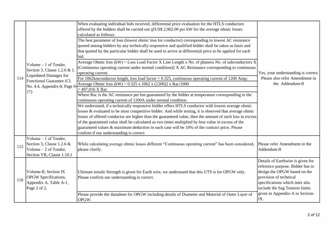
When evaluating individual bids received, differential price evaluation for the HTLS conductors
offered by the bidders shall be carried out @US$ 2,962.00 per kW for the average ohmic losses
calculated as follows:
The best parameter of loss (lowest ohmic loss for conductor) corresponding to lowest AC resistance
quoted among bidders by any technically responsive and qualified bidder shall be taken as basis and
that quoted by the particular bidder shall be used to arrive at differential price to be applied for each
bid.
Average Ohmic loss (kW) = Loss Load Factor X Line Length x No. of phasesx No. of subconductors X
(Continuous operating current under normal condition)2 X AC Resistance corresponding to continuous
operating current.
For 1062kmconductor length, loss load factor = 0.325, continuous operating current of 1200 Amp;
Average Ohmic loss (kW) = 0.325 x 1062 x (1200)2 x Rac/1000
= 497,016 X Rac
Where Rac is the AC resistance per km guaranteed by the bidder at temperature corresponding to the
continuous operating current of 1200A under normal condition.
We understand, if a technically responsive bidder offers HTLS conductor with lowest average ohmic
losses & evaluated to be most competitive bidder. And while testing, it is observed that average ohmic
losses of offered conductor are higher than the guaranteed value, then the amount of such loss in excess
of the guaranteed value shall be calculated as two times multiplied by loss value in excess of the
guaranteed values & maximum deduction in such case will be 10% of the contract price. Please
confirm if our understanding is correct.
115
Volume – 1 of Tender,
Section 3, Clause 1.2.6 &
Volume – 2 of Tender,
Section VB, Clause 1.10.1
While calculating average ohmic losses different “Continuous operating current” has been considered,
please clarify.
Please refer Amendment in the
Addendum-II
Ultimate tensile Strength is given for Earth wire, we understand that this UTS is for OPGW only.
Please confirm our understanding is correct.
Please provide the datasheet for OPGW including details of Diameter and Material of Outer Layer of
OPGW.
Volume – 1 of Tender,
Section 3, Clause 1.2.6 & 1.
Liquidated Damages for
Functional Guarantee (Cl.
No. 4.4, Appendix-8, Page 9-
17)
Volume-II, Section IX
OPGW Specifications,
Appendix A, Table A-1,
Page 2 of 2,
Details of Earthwire is given for
reference purpose. Bidder has to
design the OPGW based on the
provision of technical
specifications which inter alia
include the Sag Tension limits
given in Appendix-A to Section-
IX.
Yes, your understanding is correct.
Please also refer Amendment in
the Addendum-II
114
116
2 of 12
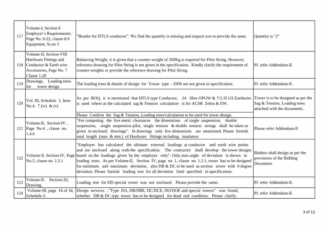
117
Volume-I, Section 6
Employer’s Requirements,
Page No. 6-22, clause 8.0
Equipment, Sr.no 5
“Bender for HTLS conductor”. We find the quantity is missing and request you to provide the same. Quantity is "2"
118
Volume-II, Section-VIII
Hardware Fittings and
Conductor & Earth wire
Accessories, Page No. 7
Clause 1.20
Balancing Weight, it is given that a counter-weight of 200Kg is required for Pilot String. However,
reference drawing for Pilot String is not given in the specification. Kindly clarify the requirement of
counter-weights or provide the reference drawing for Pilot String.
Pl. refer Addendum-II.
119Drawings, Loading trees
for tower designThe loading trees & details of design for Tower type - DDS are not given in specification. Pl. refer Addendum-II.
As per BOQ, it is mentioned that HTLS type Conductor, 24 fibre OPGW & 7/3.35 GS Earthwire
is used where as the calculated sag & Tension calculation is for ACSR Zebra & EW.
Please Confirm the Sag & Tension, Loading trees/calculation to be used for tower design.
121
Volume-II, Section-IV ,
Page No.4 , clause no.
1.4.6
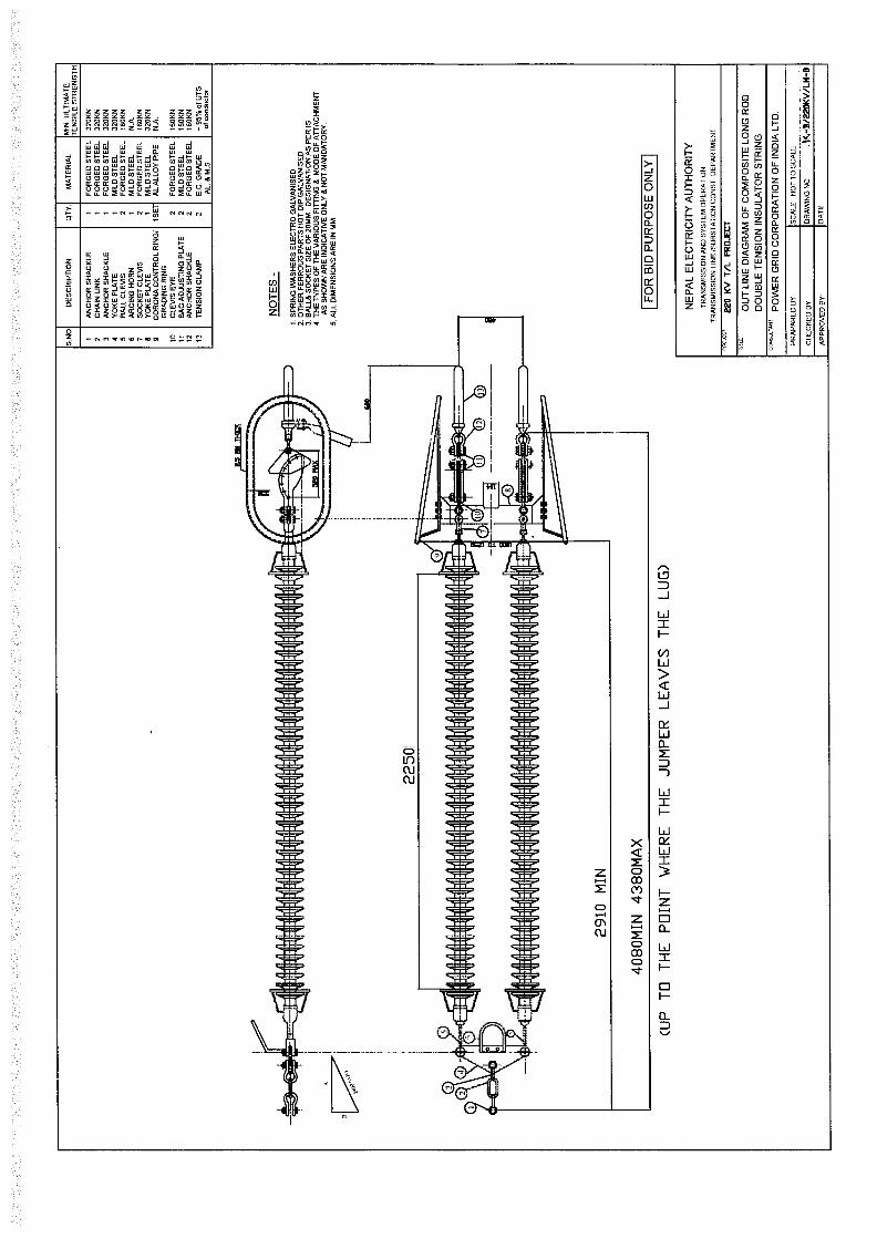
"For computing the live metal clearances the dimensions of single suspension, double
suspension, single suspension pilot, single tension & double tension strings shall be taken as
given in enclosed drawings". In drawings only few dimensions are mentioned. Please furnish
total length (max. & min.) of Hardware fittings including insulators
Please refer Addendum-II
122Volurne-ll, Section-IV, Page
No.5, clause no. 1.5.1
"Employer has calculated the ultimate external loadings at conductor and earth wire points
and are enclosed along with the specification. The contractor shall develop the tower designs
based on the loadings given by the employer only". Only max.angle of deviation is shown in
loading trees. As per Volume-Il, Section IV, page no. 1, clause no. 1.2.1, tower has to be designed
for minimum and maximum deviation, also DB & DC to be used as section tower with 0 degree
deviation. Please furnish loading tree for all deviation limit specified in spectficarton.
Bidders shall design as per the
provisions of the Bidding
Document.
123Volume-II. Section-XI,
Drawing,Loading tree for DD special tower was not enclosed. Please provide the same. Pl. refer Addendum-II.
124 Volume-III, page 16 of 34,
Schedule-3
Design services ,"Type DA, DB/DBE, DC/DCE, DO/DOE and special towers" was found,
whether DB & DC type tower has to be designed for dead end condition. Please clarify.Pl. refer Addendum-II.
120Vol. III, Schedule 2, Item
No.4. 7 (iv) & (v)
Tower is to be designed as per the
Sag & Tension, Loading trees
attached with the documents.
3 of 12

125
Volume-II, Section-IV,
Page No.2, clause no.
1.2.3.3
The towers shall be designed for providing unequal leg extensions with maximum difference
between the shortest and the longest leg of 3M for DA tower and 6M for DB, DC & DD towers.".
Please clarify how many levels of bench are allowed per tower and please furnish combinations
for leg extension per tower.
The tower has to be designed
for all possible leg extension
combinations as indicated in the
leg extension drawing. Pl. refer
amendment for drawing.
126Volume II Section-IV Page
No. 31, clause no. 2.6.1.2,
"The reactions on the footings shall be composed of the following type of loads for which these
shall be required to be checked:
a) Max. Tension or uplift along the leg slope.
b) Max. Compression or down-thrust along the leg slope.
c) Max. Horizontal shear or side thrust."
Whether foundation has to be designed for max. Uplift/down thrust case with corresponding
side thrust and checked for max.Side thrust case with its corresponding uplift/down thrust
forces. Please clarify
Bidder has to follow the
provision of the technical
specifications.
127Volume-III, page 31 of 34,
Schedule-4 Please specify with which extension tower has to be tested.
Pl. refer clause 1.14.1 of
Volume-II, Section IV.
"A Galvanized tower of each
type complete with 9 M
extension shall be subjected to
design and destruction tests … "
128Volume-I, Section 2, BDS,
ITB 21.1
It is mentioned that Bid securityshall be issued by a bank using the form included in bidding
form. If Security BG is It is mentioned that Bid securityshall be issued by a bank using the form
included in bidding form. If Security BG is issued by a bank outisde Nepal is it necessary to
counter guaranteed by any registered bank in Nepal.
No, it is not necessary to counter
guarantee the Bid Security issued
by a foreign bank by any bank in
Nepal.
129
Volume I, 2. Terms &
Procedures of Payment
(Appendix-1, Section-9)
a. The local currency payment will be made directly in contractor’s bank account by ADB or the same
will be paid by NEA. Please Confirm.
b. We understand that foreign currency payment of Advance amount, payment against completion
certificate and operational certificate will also be paid through Letter of Credit, in line with the foreign
currency payment procedure given in Appendix-1. Please confirm our understanding.
Local Currency, Advance amounts,
payment against completion
certificate and operational
certiricate shall be paid by
Withdrawal Application by the
ADB.
4 of 12

130For the standards adopted for the work of this project, shall we refer to Chinese standards? Or only
Indian standards/international standards shall be used?
Any internationally accepted
standards which ensure equal or
better performance than those
specified shall also be accepted,
subject to prior approval by the
Employer.
131The line route passes through forest. Will trees be cut off or retained to be crossed by the transmission
line?
Trees shall be cut where
clearances are not met in the ROW
as per the provision of the Bidding
Document
132The bidding document mentioned PLS-CADD and PLS-Tower software. Will other equivalent
software be accepted for the design work?No.
133The bidding document mentioned that the wind speed is 47m/s. What is the reference height and time
span for this wind speed?Please refer IS 802-1-1 (1995)
134 Please provide the single line diagram and weight of each steel tower.It is in the scope of the Bidder to
furnish them
135 Please provide the geological data along the line route.It is in the scope of the Bidder to
collect them
136
Clause no. 2.5 of Section 3
“Evaluation and
Qualification Criteria”, Item
No. 2 (ii)
It is mentioned that for HTLS Conductor the manufacturer Must have min 10 (ten) years manufacturing
experience of ACSR/ AAAC/ AACSR conductors of min 400 sq mm size in general and must have
manufacturing experience of HTLS conductors for the last 5 (five) years.
In context to above, please confirm what does ‘HTLS’ word means in above clause?
Please refer Addendum-II
137Vol I, Section 3, EQC,
2.5, 2 (ii)
HTLS Conductor the manufacturer Must have min 10 (ten) years manufacturing experience of
ACSR/ AAAC/ AACSR conductors of min 400 sq mm size in general and must have
manufacturing experience of HTLS conductors for the last 5 (five) years. Offered technology
means, can we offer any HTLS conductor apart from ACCC, Invar Conductor? In context to
above, please confirm what does ‘HTLS’ word means in above clause?
Please Confirm.
HTLS conductor shall mean any
HTLS conductor in general
5 of 12
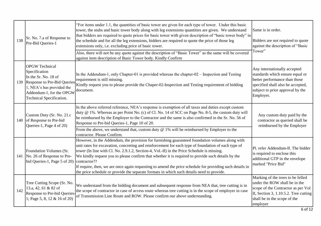
“For items under 1.1, the quantities of basic tower are given for each type of tower. Under this basic
tower, the stubs and basic tower body along with leg extensions quantities are given. We understand
that bidders are required to quote prices for basic tower with given description of “basic tower body” in
the schedule and for all the leg extensions, bidders are required to quote the price of those leg
extensions only, i.e. excluding price of basic tower.
Also, there will not be any quote against the description of “Basic Tower” as the same will be covered
against item description of Basic Tower body. Kindly Confirm
139
OPGW Technical
Specification
In the Sr. No. 18 of
Response to Pre-Bid Queries-
1, NEA’s has provided the
Addendum-1, for the OPGW
Technical Specification.
In the Addendum-1, only Chapter-01 is provided whereas the chapter-02 – Inspection and Testing
requirement is still missing.
Kindly request you to please provide the Chaper-02-Inspection and Testing requirement of bidding
document.
Any internationally accepted
standards which ensure equal or
better performance than those
specified shall also be accepted,
subject to prior approval by the
Employer.
In the above referred reference, NEA’s response is exemption of all taxes and duties except custom
duty @ 1%. Whereas as per Point No. (c) of Cl. No. 14 of SCC on Page No. 8-5, the custom duty will
be reimbursed by the Employer to the Contractor and the same is also confirmed in the Sr. No. 56 of
Response to Pre-bid Queries-1, Page 10 of 20.
From the above, we understand that, custom duty @ 1% will be reimbursed by Employer to the
contractor. Please Confirm.
141
Foundation Volumes (Sr.
No. 26 of Response to Pre-
bid Queries-1, Page 5 of 20)
However, in the Addendum, the provision for furnishing guaranteed foundation volumes along with
unit rates for excavation, concreting and reinforcement for each type of foundation of each type of
tower (In line with Cl. No. 2.9.1.2, Section-4, Vol.-II) in the Price Schedule is missing.
We kindly request you to please confirm that whether it is required to provide such details by the
contractor??
If require, then, we are once again requesting to amend the price schedule for providing such details in
the price schedule or provide the separate formats in which such details need to provide.
Pl. refer Addendum-II. The bidder
is required to enclose this
additional GTP in the envelope
marked "Price Bid"
142
Tree Cutting Scope (Sr. No.
13.a, 42, 61 & 82 of
Response to Pre-bid Queries-
1; Page 5, 8, 12 & 16 of 20)
We understand from the bidding document and subsequent response from NEA that, tree cutting is in
the scope of contractor in case of access route whereas tree cutting is in the scope of employer in case
of Transmission Line Route and ROW. Please confirm our above understanding.
Marking of the trees to be felled
under the ROW shall be in the
scope of the Contractor as per Vol
II, Section 3, 1.10.5.2. Tree cutting
shall be in the scope of the
employer
Same is in order.
Bidders are not required to quote
against the description of “Basic
Tower”
140
Custom Duty (Sr. No. 21.c
of Response to Pre-bid
Queries-1, Page 4 of 20)
Any custom duty paid by the
contractor as queried shall be
reimbursed by the Employer
138Sr. No. 7.a of Response to
Pre-Bid Queries-1
6 of 12

143
8. Sr. No. 76 of Response to
Pre-bid Queries-1; Page 15
of 20)
There is no response given in the above referred clarification. We are once again mentioning below the
clarification requested.
“While calculating average ohmic losses different “Continuous operating current” has been considered,
please clarify”. (Reference – Cl. 1.2.6, Section-3, Vol.-1 & Cl. 1.10.1, Section-VA, Vol.-II). Kindly
request you to please clarify the same.
Please refer Addendum II
2.(i) The offered conductor technology must have been in successful manufacturing and supply for at
least last ten years.
Offered technology means, can we offer any HTLS conductor apart from ACCC, Invar Conductor??
Please Confirm.
2.(iii) Must have manufactured, tested and supplied at least 1000 km of HTLS conductor of the same
technology as that being offered in the bid as a main supplier over last five (5) years period as on date
of bid submission and 15% of the supplied quantity should have been in satisfactory operation in the
field for at least one year as on originally scheduled date of bid opening.
Manufactured and tested at least 1000 kms Cumulative supply of HTLS technology product by main
supplier over last 5 ears period as on bid submission and 15% of supplied quantity should have been in
satisfactory operation in the field for at least one year as on originally scheduled date of bid opening.
Request to please amend accordingly.
It is mentioned as Material of LM-6 high strength Al. Alloy for stock-bridge Dampers.
If we propose Al. 356-T6 which has higher properties then LM-6 Al. alloy (as Per ASTM Standard)
Clamping Bolt shall be provide with Self Locking nuts.
In Case the design of Stockbridge Dampers does not have any nut in assemblies. Whether self-locking
nut required when we are going tightened into HTLS Conductor covered by Armor Rods
Damper clamp is required to be casted over the messenger cable and offer sufficient permanent grip.
We offer sufficient permanent grip, our clamp is not cast on the messenger cable, but crimped
146 Clause 2.4.3 (Page -15)Self Locking nuts shall be required
with Clamping Bolt only.
147As Per Tender Clause 2.4.6
(Page -16),
Bidders shall follow the provision
of technical specifications.
145As Per Tender Clause 2.4.3
(Page -15)
Pl. refer to note given below the
Table-1 on Page-12 of Section-
VIII, Volume-II in this regard.
144
HTLS Conductor (Cl. No.
2.5, Section-3, Vol.-1, Page
3-9)
Please refer Amendment of
Addendum II
7 of 12
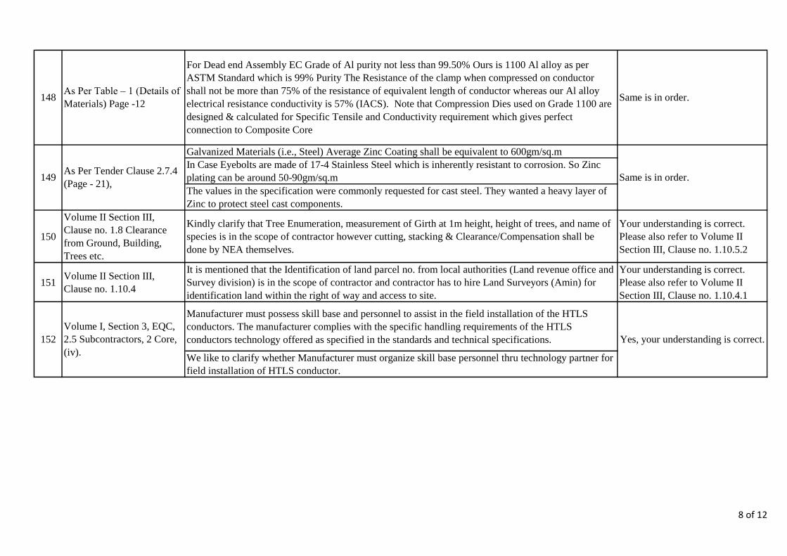
Galvanized Materials (i.e., Steel) Average Zinc Coating shall be equivalent to 600gm/sq.m
In Case Eyebolts are made of 17-4 Stainless Steel which is inherently resistant to corrosion. So Zinc
plating can be around 50-90gm/sq.m
The values in the specification were commonly requested for cast steel. They wanted a heavy layer of
Zinc to protect steel cast components.
150
Volume II Section III,
Clause no. 1.8 Clearance
from Ground, Building,
Trees etc.
Kindly clarify that Tree Enumeration, measurement of Girth at 1m height, height of trees, and name of
species is in the scope of contractor however cutting, stacking & Clearance/Compensation shall be
done by NEA themselves.
Your understanding is correct.
Please also refer to Volume II
Section III, Clause no. 1.10.5.2
151Volume II Section III,
Clause no. 1.10.4
It is mentioned that the Identification of land parcel no. from local authorities (Land revenue office and
Survey division) is in the scope of contractor and contractor has to hire Land Surveyors (Amin) for
identification land within the right of way and access to site.
Your understanding is correct.
Please also refer to Volume II
Section III, Clause no. 1.10.4.1
Manufacturer must possess skill base and personnel to assist in the field installation of the HTLS
conductors. The manufacturer complies with the specific handling requirements of the HTLS
conductors technology offered as specified in the standards and technical specifications.
We like to clarify whether Manufacturer must organize skill base personnel thru technology partner for
field installation of HTLS conductor.
148As Per Table – 1 (Details of
Materials) Page -12
152
Volume I, Section 3, EQC,
2.5 Subcontractors, 2 Core,
(iv).
Yes, your understanding is correct.
For Dead end Assembly EC Grade of Al purity not less than 99.50% Ours is 1100 Al alloy as per
ASTM Standard which is 99% Purity The Resistance of the clamp when compressed on conductor
shall not be more than 75% of the resistance of equivalent length of conductor whereas our Al alloy
electrical resistance conductivity is 57% (IACS).Note that Compression Dies used on Grade 1100 are
designed & calculated for Specific Tensile and Conductivity requirement which gives perfect
connection to Composite Core
Same is in order.
149As Per Tender Clause 2.7.4
(Page - 21),Same is in order.
8 of 12
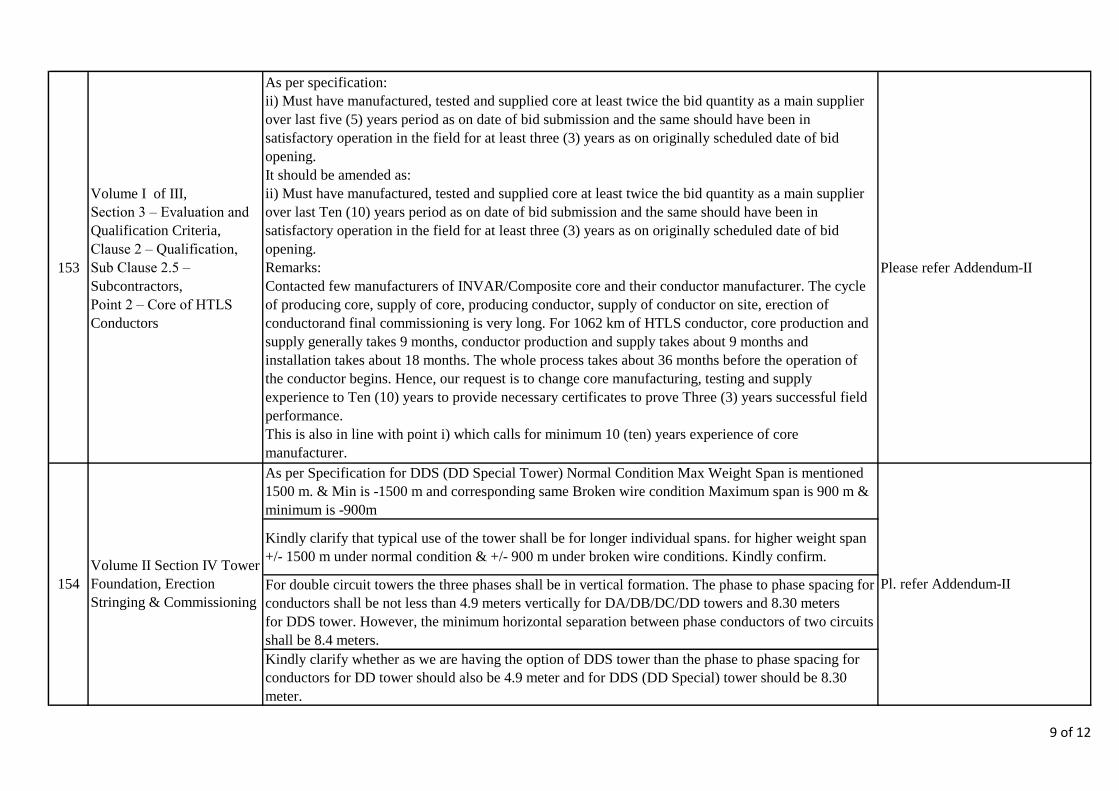
153
Volume I of III,
Section 3 – Evaluation and
Qualification Criteria,
Clause 2 – Qualification,
Sub Clause 2.5 –
Subcontractors,
Point 2 – Core of HTLS
Conductors
As per specification:
ii) Must have manufactured, tested and supplied core at least twice the bid quantity as a main supplier
over last five (5) years period as on date of bid submission and the same should have been in
satisfactory operation in the field for at least three (3) years as on originally scheduled date of bid
opening.
It should be amended as:
ii) Must have manufactured, tested and supplied core at least twice the bid quantity as a main supplier
over last Ten (10) years period as on date of bid submission and the same should have been in
satisfactory operation in the field for at least three (3) years as on originally scheduled date of bid
opening.
Remarks:
Contacted few manufacturers of INVAR/Composite core and their conductor manufacturer. The cycle
of producing core, supply of core, producing conductor, supply of conductor on site, erection of
conductorand final commissioning is very long. For 1062 km of HTLS conductor, core production and
supply generally takes 9 months, conductor production and supply takes about 9 months and
installation takes about 18 months. The whole process takes about 36 months before the operation of
the conductor begins. Hence, our request is to change core manufacturing, testing and supply
experience to Ten (10) years to provide necessary certificates to prove Three (3) years successful field
performance.
This is also in line with point i) which calls for minimum 10 (ten) years experience of core
manufacturer.
Please refer Addendum-II
As per Specification for DDS (DD Special Tower) Normal Condition Max Weight Span is mentioned
1500 m. & Min is -1500 m and corresponding same Broken wire condition Maximum span is 900 m &
minimum is -900m
Kindly clarify that typical use of the tower shall be for longer individual spans. for higher weight span
+/- 1500 m under normal condition & +/- 900 m under broken wire conditions. Kindly confirm.
For double circuit towers the three phases shall be in vertical formation. The phase to phase spacing for
conductors shall be not less than 4.9 meters vertically for DA/DB/DC/DD towers and 8.30 meters
for DDS tower. However, the minimum horizontal separation between phase conductors of two circuits
shall be 8.4 meters.
Kindly clarify whether as we are having the option of DDS tower than the phase to phase spacing for
conductors for DD tower should also be 4.9 meter and for DDS (DD Special) tower should be 8.30
meter.
154
Volume II Section IV Tower
Foundation, Erection
Stringing & Commissioning
Pl. refer Addendum-II
9 of 12

155
Volume III of III,
Schedule No.4 – Installation
Services,
Point No. 14
Cost for supervision works to be imparted by the principal Core Manufacturer during the installation of
HTLS conductor at site
Engineer – 180 MDays
Supervisor – 180 MDays
Our recommendation is to consider 180 man days of Supervisor and Engineer per crew. In-case there
are multiple crews on the site then each crew will have its own Engineer and Supervisor team for
effective supervision.
Yes, your understanding is correct
156
Volume II
Section VIII
Hardware Fittings and
Conductor & Earthwire
Accessories
For rigid spacer and vibration damper the conductor is twin bundled, the conductor is twin bundled, we
like to get confirmation that the qty in BOQ which means that one rigid spacer with one vibration
damper
Query is not clear.
157
Volume II
Section VIII
Hardware Fittings and
Conductor & Earthwire
Accessories
Drawings
As per drawings attached arcing gap is 2,400 mm from the calculation on given data for insulator, it is
not possible to reach required 2,400 mm please confirm whether 2,400 mm is just for reference and
actual if less from calculation is also acceptable to NEA.
Pl. refer Addendum-II.
"Reference drawing for leg extension arrangement is enclosed in the Bid Document".
The Leg extension arrangement drawing was not enclosed in bid document. We request you to
please provide the drawing.
159Kindly furnish following
documents also:-The sketch of tower showing arrangement of leg extensions. Pl. refer Addendum-II.
160
In the Bid Security Bank Guarantee, it is said ..... For the execution of (name of contratct). .. Under
Invitation for Bids No. ICB-PMD-KGTCP-072/73-04("the IFB"), can we specify the name of contract as "
Design, Supply, Installation and Commissioning of Kusma-New Butwal 220kV Transmission Line."
Yes, you may.
161
In Bidding Document Volume I-Section 8, for article 14.5.2, Import License, it is said "The Employer will
assist the Contractor to obtain necessary permits for import of such equipment and material into Nepal.
Import license fees or any other charges shall be at the cost of Contractor." What is the cost rate for Import
license fees or any other charges?
All such fees if any shall be borne
by the Contractor. Please refer
www.ird.gov.np
158
In Volume-Il, Section IV ,
page no. 2 ,clause no.
1.2.3.1
Pl. refer Addendum-II.
10 of 12

Whether Q235 and Q345 steel according to Chinese standard (of which the yield strength are respectively
235 MPa and 345 MPa) can be used instead of E250 and E350 grade of steel in the invitation for bid, which
as shown in the table. According to experience, using Chinese standard steel Q235 and Q345 can completely
guarantee the quality and safety of steel tower and the tower weighs almost the same.
Invitation for bid Chinese standard
steel grade yield strength (MPa) steel grade yield strength (MPa)
E250 250 Q235 235
E350 350 Q345 345
163
Whether bored piles of 800 mm diameter can be used in the project. In the design of transmission lines in
China, bored piles of 800 mm diameter have been large-scale used, which can fully guarantee the
engineering quality and safety.
This shall be as per the provisions
of the Bidding Document
Whether the foundation of other forms can be used. For example, when the foundation is located in the
mountain but the slope is steep, using the anchor foundation makes the excavated volume too big, therefore
we suggest using the rock embedded foundation. When the foundation is located in the hilly area, using the
PAD foundation makes the excavated volume too big, therefore we suggest using the excavating pile
foundation.
165
Should we close the road when crossing national highways? Should we cut off the power when crossing
power line? Should we close the river when crossing navigable river? If necessary, who is responsible for
handling procedures, whether other measures need to be monitored?
The employer shall facilitate
during such instances.
164
162This shall be as per the provisions
of the Bidding Document
This shall be as per the provisions
of the Bidding Document
11 of 12

166Response to Pre bid queries
- 1, Sl No. 34
Sag at maximum temperature for HTLS conductor is mentioned as 9.75m in technical specification As
per your response it is confirmed to use this sag for fixing tower height for other bidders inquiry. In
contrast in tender document you have furnished sag tension calculation with sag of 10.36m at 80 deg
temperature. please confirm which Sag is to be considered .
Please refer Addendum-II
167 Volume-II, Section-III,
Page No. 12, clause no.3.4.1
"CBIP Manual on transmission line towers, Chapter – 10 Foundations"
Please specify the publication no. 268 or 323 to be referred.
The latest publication to be
reffered. However, the provision of
technical specifications shall
prevail, in case, of any
descrepancy.
168
Custom Duty (Sr. No. 21.c
of Response to Pre-bid
Queries-1, Page 4 of 20)
In the above referred reference, NEA’s response is exemption of all taxes and duties except custom
duty @ 1%.
Whereas as per Point No. (c) of Cl. No. 14 of SCC on Page No. 8-5, the custom duty will be
reimbursed by the Employer to the Contractor and the same is also confirmed in the Sr. No. 56 of
Response to Pre-bid Queries-1, Page 10 of 20.
From the above, we understand that, custom duty @ 1% will be reimbursed by Employer to the
contractor.
Please Confirm.
Yes your understanding is correct
12 of 12

Page 1 of 5
Amendment-II to Bidding Documents, Volume-I
Clause No. Existing Amendment
Volume-I,
Section-3, Clause
no. 1.2.6
1.2.6 Specific additional criteria
When evaluating individual bids received, differential price
evaluation for the HTLS conductors offered by the bidders shall
be carried out @US$ 2,962.00 per kWfor the average ohmic
losses calculated as follows:
The best parameter of loss (lowest ohmic loss for conductor)
corresponding to lowest AC resistance quoted among bidders
by any technically response ve and qualified bidder shall be
taken as basis and that quoted by the particular bidder shall be
used to arrive at differential price to be applied for each bid.
Average Ohmic loss (kW) = Loss Load Factor X Line Length x
No. of phasesx No. of subconductors X (Continuous operating
current under normal condition)2 X AC Resistance
corresponding to continuous operating current.
For 1062km conductor length, loss load factor = 0.325,
continuous operating current of 1200 Amp;
Average Ohmic loss (kW) = 0.325 x 1062 x (1200)2 x
Rac/1000
= 497,016 X Rac
Where Rac is the AC resistance per km guaranteed by the
bidder at temperature corresponding to the continuous operating
current of 1200A under normal condition.
1.2.6 Specific additional criteria
When evaluating individual bids received, differential price
evaluation for the HTLS conductors offered by the bidders shall
be carried out @US$ 2,962.00 per kWfor the average ohmic
losses calculated as follows:
The best parameter of loss (lowest ohmic loss for conductor)
corresponding to lowest AC resistance quoted among bidders by
any technically responsive and qualified bidder shall be taken as
basis and that quoted by the particular bidder shall be used to
arrive at differential price to be applied for each bid.
Average Ohmic loss (kW) = Loss Load Factor X Line Length x
No. of phasesx No. of subconductors X (Continuous operating
current under normal condition)2 X AC Resistance
corresponding to continuous operating current.
For 1062km conductor length, loss load factor = 0.325,
continuous operating current of 615 Amp;
Average Ohmic loss (kW) = 0.325 x 1062 x (615)2 x Rac/1000
= 130544.36X Rac
Where Rac is the AC resistance per km guaranteed by the bidder
at temperature corresponding to the continuous operating current
of 615A under normal condition.
Volume – I
Section 3,
Sub Clause 2.5:
Subcontractor
Point 2 – Core
HTLS Conductor
Page (3 of 9)
"Must have manufactured, tested and supplied core at least
twice the bid quantity as a main supplier over last five (5) years
period as on date of bid submission and the same should have
been in satisfactory operation in the field for at least three (3)
years as on originally scheduled date of bid opening”.
"Must have manufactured, tested and supplied core at least twice
the bid quantity as a main supplier over last ten (10) years period
as on date of bid submission and the same should have been in
satisfactory operation in the field for at least three (3) years as on
originally scheduled date of bid opening”.

Page 2 of 5
Amendment-II to Bidding Documents, Volume-II
Clause No. Existing Amendment
Volume II,
Section VA 1.4.1 Particulars Limiting value
Tension at every day condition
(32°C, no wind)
Not exceeding
25% of UTS of
proposed
conductor
Sag at designed maximum
temperature (corresponding to 1200
amperes and ambient conditions
specified at 1.2.1)
≤9.75 meters
Tension at following wind pressure:-
i) Tension at 32 deg C, full wind
(166.8kg/m2)
≤ 6892kg & not
exceeding 70% of
UTS of proposed
conductor
Particulars Limiting value
Tension at every day condition
(32°C, no wind)
Not exceeding
25% of UTS of
proposed
conductor
Sag at designed maximum
temperature (corresponding to 1200
amperes and ambient conditions
specified at 1.2.1)
≤10.36 meters
Tension at following wind pressure:-
i) Tension at 32 deg C, full wind
(166.8kg/m2)
≤ 6892kg & not
exceeding 70% of
UTS of proposed
conductor
Volume-II,
Section-IV,
Clause 1.1.3
The towers shall be of the following types:
A) Double Circuit towers (DA, DB, DC & DD/DDE)
B) Special towers.
The towers shall be of the following types:
A) Double Circuit towers (DA, DB, DC & DD/DDE)
B) Special towers (DDS)

Page 3 of 5
Volume-II,
Section-IV,
Clause 1.2.1
The towers for 220 kV Lines are classified as given below:
The towers for 220 kV Lines are classified as given below: _________________________________________________
Type of Deviation Typical Use
Tower Limit
_________________________________________________
DDS 0 - 60 deg. a) Angle tower with tension insulator string used for very long spans.
b) Also to be used for uplift forces resulting from an uplift span up to 900m under broken wire condition.
c) Complete dead end. _______________________________________________
Note: The DDS tower shall also meet all the technical requirements specified for DD type tower, unless stated.
Volume-II,
Section-IV,
Clause 1.6.2
Conductor and Earthwire Configuration For double circuit towers the three phases shall be in vertical formation. The phase to phase spacing for conductors shall be not less than 4.9 meters vertically for DA/DB/DC towers and 8.30 meters for DD tower. However, the minimum horizontal separation between phase conductors of two circuits shall be 8.4 meters.
Conductor and Earthwire Configuration For double circuit towers, the three phases shall be in vertical formation. The phase to phase spacing for conductors shall be not less than 4.9 meters vertically for DA/DB/DC towers, 8.30 meters for DD tower and 11.80 meters for DDS tower. However, the minimum horizontal separation between phase conductors of two circuits shall be 8.4 meters.
Volume II,
Section IV, 3.1.1
The stringing equipment shall be of sufficient capacity to string simultaneously a bundle of TWIN ZEBRA Conductors.
The stringing equipment shall be of sufficient capacity to string simultaneously a bundle of TWIN HTLS Conductors.
Volume-II,
Drawings
Drawings
Insulator String Drawings
Drawings
Insulator String Drawings (Revised)
Page 4 of 5
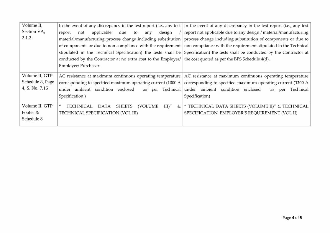
Volume II,
Section VA,
2.1.2
In the event of any discrepancy in the test report (i.e., any test
report not applicable due to any design /
material/manufacturing process change including substitution
of components or due to non compliance with the requirement
stipulated in the Technical Specification) the tests shall be
conducted by the Contractor at no extra cost to the Employer/
Employer/ Purchaser.
In the event of any discrepancy in the test report (i.e., any test
report not applicable due to any design / material/manufacturing
process change including substitution of components or due to
non compliance with the requirement stipulated in the Technical
Specification) the tests shall be conducted by the Contractor at
the cost quoted as per the BPS Schedule 4(d).
Volume II, GTP
Schedule 8, Page
4, S. No. 7.16
AC resistance at maximum continuous operating temperature
corresponding to specified maximum operating current (1000 A
under ambient condition enclosed as per Technical
Specification )
AC resistance at maximum continuous operating temperature
corresponding to specified maximum operating current (1200 A
under ambient condition enclosed as per Technical
Specification)
Volume II, GTP
Footer &
Schedule 8
“ TECHNICAL DATA SHEETS (VOLUME III)” &
TECHNICAL SPECIFICATION (VOL III)
“ TECHNICAL DATA SHEETS (VOLUME II)” & TECHNICAL
SPECIFICATION, EMPLOYER’S REQUIREMENT (VOL II)

Page 5 of 5
Amendment-II to Bidding Documents, Volume-III
Clause No. Existing Amendment
Volume III,
Schedule 4(a)
4.3 Tension Tower DC
b) Foundation for +1.5m, +3m, +4.5m +6m, +7.5m, +9m Extension
iii) Partially Submerged Foundation Nos. 2
v) Wet Black Cotton Nos. 3
4.3 Tension Tower DC
b) Foundation for +1.5m, +3m, +4.5m +6m, +7.5m, +9m Extension
iii) Partially Submerged Foundation Nos. 3
v) Wet Black Cotton Nos. 4
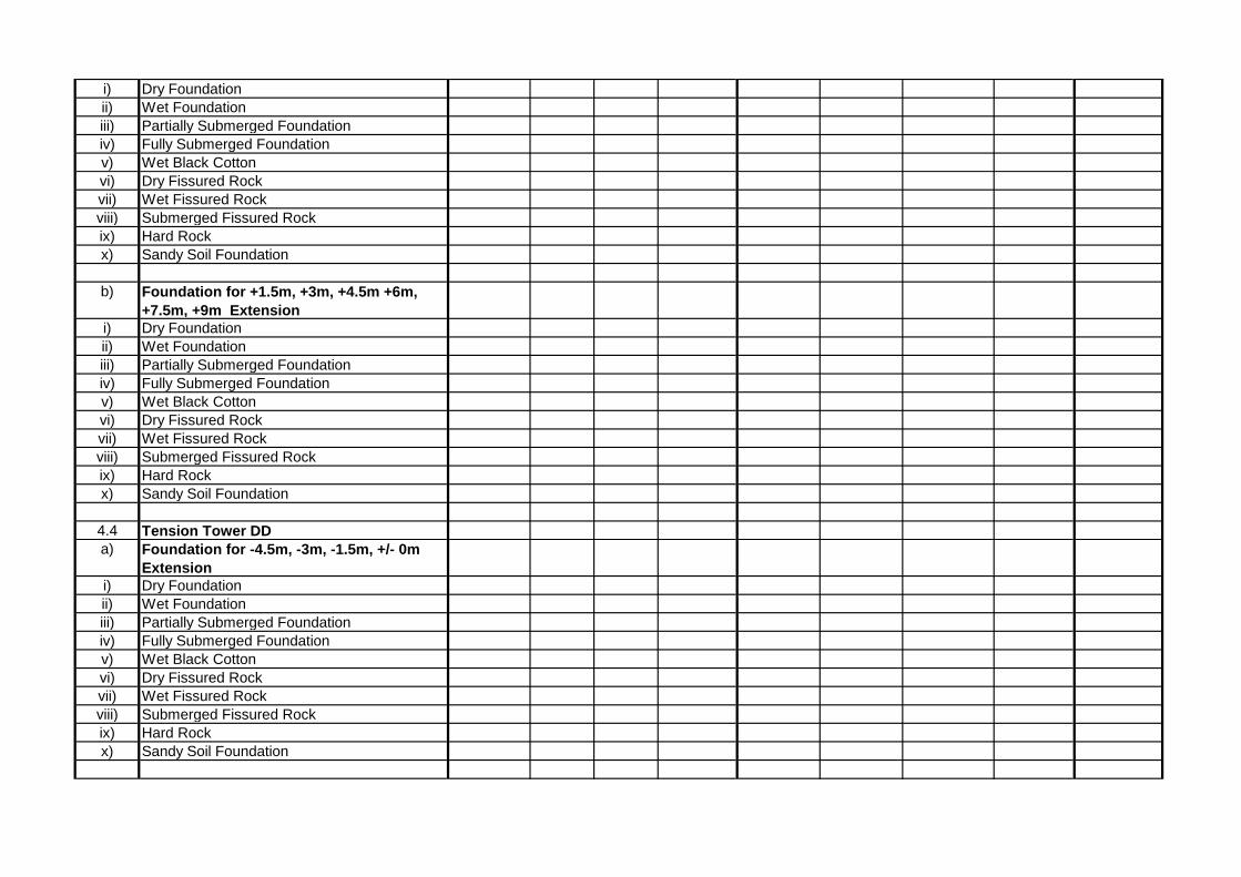
4.4 Tension Tower DD
a) Foundation for -4.5m, -3m, -1.5m, +/- 0m Extension
v) Wet Black Cotton Nos. 4
4.4 Tension Tower DD
a) Foundation for -4.5m, -3m, -1.5m, +/- 0m Extension
v) Wet Black Cotton Nos. 3
4.4 Tension Tower DD
b) Foundation for +1.5m, +3m, +4.5m +6m, +7.5m, +9m Extension
vi) Dry Fissured Rock Nos. 6
4.4 Tension Tower DD
b) Foundation for +1.5m, +3m, +4.5m +6m, +7.5m, +9m Extension
vi) Dry Fissured Rock Nos. 5
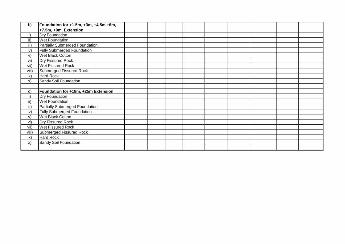
Volume-III,
Price Schedule-3
Design Services Type DA, DB/DBE, DC/DCE, DD/DDE and special towers
Design Services Type DA, DB, DC, DD/DDE, DDS and special towers

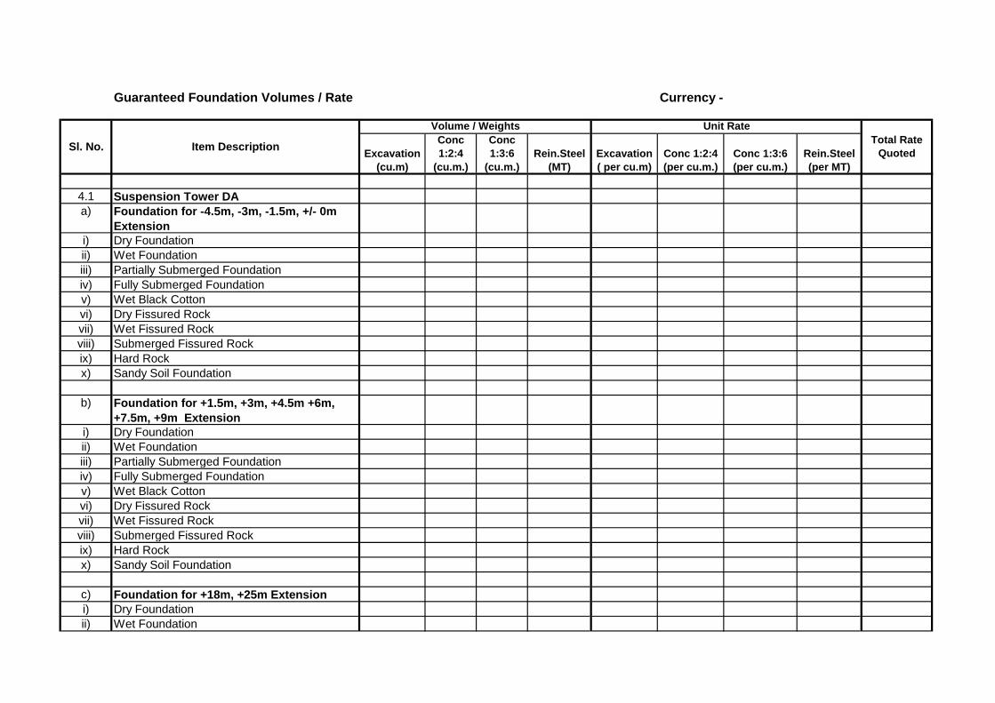
Guaranteed Foundation Volumes / Rate Currency -
4.1 Suspension Tower DA
a) Foundation for -4.5m, -3m, -1.5m, +/- 0m
Extension
i) Dry Foundation
ii) Wet Foundation
iii) Partially Submerged Foundation
iv) Fully Submerged Foundation
v) Wet Black Cotton
vi) Dry Fissured Rock
vii) Wet Fissured Rock
viii) Submerged Fissured Rock
ix) Hard Rock
x) Sandy Soil Foundation
b) Foundation for +1.5m, +3m, +4.5m +6m,
+7.5m, +9m Extension
i) Dry Foundation
ii) Wet Foundation
iii) Partially Submerged Foundation
iv) Fully Submerged Foundation
v) Wet Black Cotton
vi) Dry Fissured Rock
vii) Wet Fissured Rock
viii) Submerged Fissured Rock
ix) Hard Rock
x) Sandy Soil Foundation
c) Foundation for +18m, +25m Extension
i) Dry Foundation
ii) Wet Foundation
Total Rate
Quoted Rein.Steel
(per MT)
Item DescriptionSl. No.
Volume / Weights Unit Rate
Conc
1:2:4
(cu.m.)
Conc
1:3:6
(cu.m.)
Rein.Steel
(MT)
Excavation
( per cu.m)
Conc 1:2:4
(per cu.m.)
Conc 1:3:6
(per cu.m.)
Excavation
(cu.m)
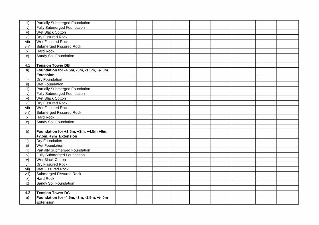
iii) Partially Submerged Foundation
iv) Fully Submerged Foundation
v) Wet Black Cotton
vi) Dry Fissured Rock
vii) Wet Fissured Rock
viii) Submerged Fissured Rock
ix) Hard Rock
x) Sandy Soil Foundation
4.2 Tension Tower DB
a) Foundation for -4.5m, -3m, -1.5m, +/- 0m
Extension
i) Dry Foundation
ii) Wet Foundation
iii) Partially Submerged Foundation
iv) Fully Submerged Foundation
v) Wet Black Cotton
vi) Dry Fissured Rock
vii) Wet Fissured Rock
viii) Submerged Fissured Rock
ix) Hard Rock
x) Sandy Soil Foundation
b) Foundation for +1.5m, +3m, +4.5m +6m,
+7.5m, +9m Extension
i) Dry Foundation
ii) Wet Foundation
iii) Partially Submerged Foundation
iv) Fully Submerged Foundation
v) Wet Black Cotton
vi) Dry Fissured Rock
vii) Wet Fissured Rock
viii) Submerged Fissured Rock
ix) Hard Rock
x) Sandy Soil Foundation
4.3 Tension Tower DC
a) Foundation for -4.5m, -3m, -1.5m, +/- 0m
Extension
i) Dry Foundation
ii) Wet Foundation
iii) Partially Submerged Foundation
iv) Fully Submerged Foundation
v) Wet Black Cotton
vi) Dry Fissured Rock
vii) Wet Fissured Rock
viii) Submerged Fissured Rock
ix) Hard Rock
x) Sandy Soil Foundation
b) Foundation for +1.5m, +3m, +4.5m +6m,
+7.5m, +9m Extension
i) Dry Foundation
ii) Wet Foundation
iii) Partially Submerged Foundation
iv) Fully Submerged Foundation
v) Wet Black Cotton
vi) Dry Fissured Rock
vii) Wet Fissured Rock
viii) Submerged Fissured Rock
ix) Hard Rock
x) Sandy Soil Foundation
4.4 Tension Tower DD
a) Foundation for -4.5m, -3m, -1.5m, +/- 0m
Extension
i) Dry Foundation
ii) Wet Foundation
iii) Partially Submerged Foundation
iv) Fully Submerged Foundation
v) Wet Black Cotton
vi) Dry Fissured Rock
vii) Wet Fissured Rock
viii) Submerged Fissured Rock
ix) Hard Rock
x) Sandy Soil Foundation
b) Foundation for +1.5m, +3m, +4.5m +6m,
+7.5m, +9m Extension
i) Dry Foundation
ii) Wet Foundation
iii) Partially Submerged Foundation
iv) Fully Submerged Foundation
v) Wet Black Cotton
vi) Dry Fissured Rock
vii) Wet Fissured Rock
viii) Submerged Fissured Rock
ix) Hard Rock
x) Sandy Soil Foundation
c) Foundation for +18m, +25m Extension
i) Dry Foundation
ii) Wet Foundation
iii) Partially Submerged Foundation
iv) Fully Submerged Foundation
v) Wet Black Cotton
vi) Dry Fissured Rock
vii) Wet Fissured Rock
viii) Submerged Fissured Rock
ix) Hard Rock
x) Sandy Soil Foundation


-4.5
-3.0
-1.5
±0
+1.5
+3.0 +3.0
+4.5
+6.0
+7.5
+9.0
BASIC BODY
NEPAL ELECTRICITY AUTHORITY
TRANSMISSION LINE /SUBSTATION CONST. DEPARTMENT
TRANSMISSION AND SYSTEM OPERATION
KUSHMA-NEW BUTWAL 220 KV T/L PROJECT
PROJECT :
TOWER EXTENSIONS
TILTE :
POWERGRID CORPORATION OF INDIA LTD.CONSULTANT :
PREPARED BY :
CHECKED BY :
APPROVED BY :
SCALE : NOT TO SCALE
DRG. NO. - K-B/220KV/011
DATE :
BID PURPOSE ONLY

ASSM 5, 5A: SECURITY CONDITION (CONDBROKEN)
ASSM 2, 3, 4, 2A, 3A, 4A: SECURITYCONDITION (GW BROKEN)
NOTES:1. Wind Span 350 m (NC), 210 m (BWC)2. Weight Span 1500 m (NC), 900 m (BWC) Maximum -1500 m (NC), -900 m (BWC) Minimum3. All ultimate loads are in kg.4. Bracketed figures indicate Minimum Vertical Load/Uplift Loads5. Angle of Deviation = 60 °6. Wind Load (Full Wind) on Tower Body shall be considered extra in all above assumptions.7. S.W. (Self Weight) of Tower shall be considered Extra.8.Assm. 2A, 3A & 4A indicates Right Side GW Broken conditions.9. Assm. 5A indicates Right Side Conductors Broken condition.10. Insulator Strings Weight & Wind on Strings are included in above Load.
1880
445(-425)
4418(-2018)
9343
SW SW
SW
ASSM 1: RELIABLITY CONDITION(NORMAL)
2
7
7
7
NEPAL ELECTRICITY AUTHORITY
17609
735(-715)
3613
LOAD TREES FOR TYPE- DDS
6363(-3963)
1
3
3
1
4
3613
1
3
3
1
4
735(-715)
17609
17609
17609
17609
17609
6363(-3963)
6363(-3963)
6363(-3963)
6363(-3963)
6363(-3963)
735(-715)
3613
735(-715)
735(-715)
3613 3613
4418(-2018)
9343
17609
6363(-3963)
17609
6363(-3963)
17609
6363(-3963)
17609
6363(-3963)
4418(-2018)
9343
1
3
3
1
4
4418(-2018)
9343
1
3
3
1
4
4418(-2018)
9343
1
3
3
1
4
17609
6363(-3963)
17609
6363(-3963)
17609
6363(-3963)
SHEET NO. 1 OF 4DRG. No.
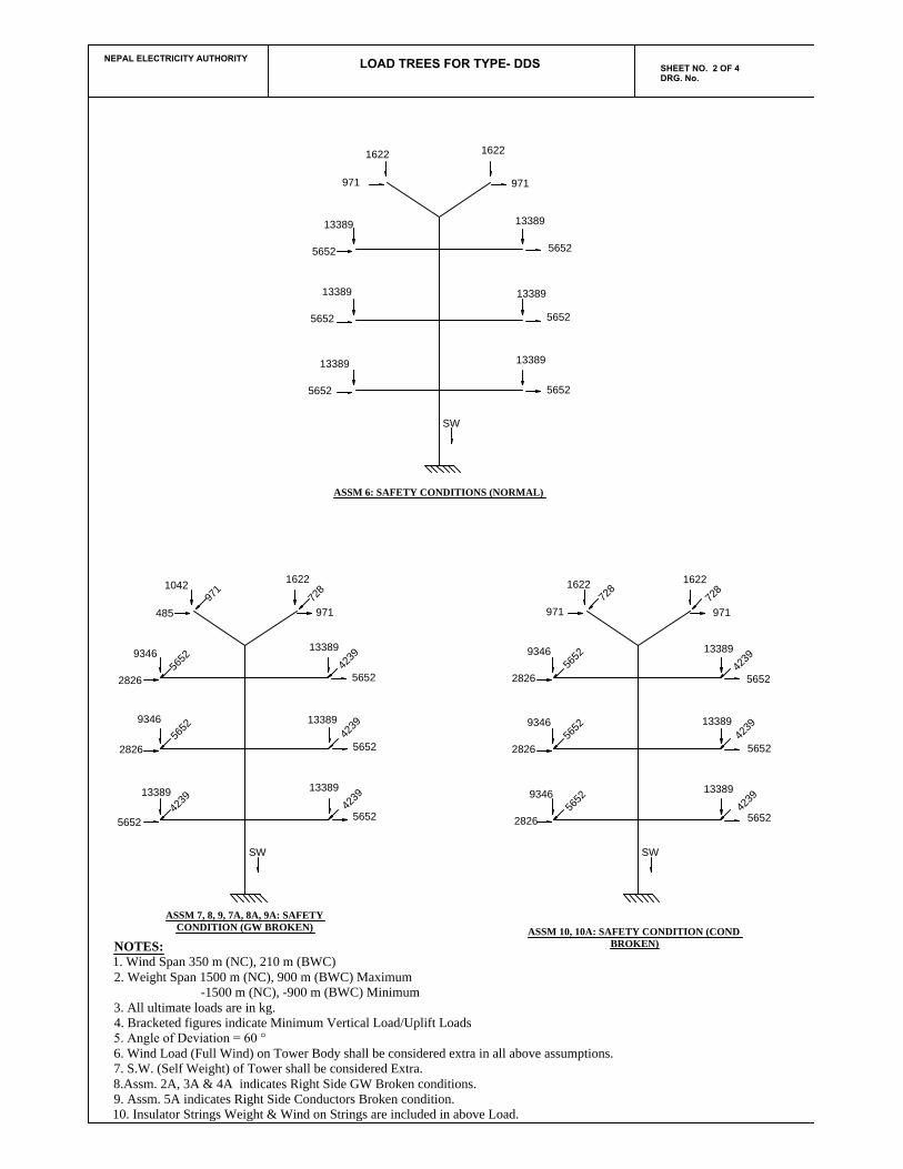
ASSM 10, 10A: SAFETY CONDITION (CONDBROKEN)
ASSM 7, 8, 9, 7A, 8A, 9A: SAFETYCONDITION (GW BROKEN)
ASSM 6: SAFETY CONDITIONS (NORMAL)
SW
2826
9346
9
7
1
485
1042
SW
SW
LOAD TREES FOR TYPE- DDS
5652
13389
5
6
5
2
7
2
8
4
2
3
9
1622
971
2826
5
6
5
2
5652
13389
1622
971
5652
13389
5652
13389
13389
13389
13389
5652
5652
5652
9346
4
2
3
9
4
2
3
9
4
2
3
9
13389
13389
13389
5652
5652
5652
1622
971
7
2
8
1622
971
1622
971
7
2
8
2826
9346
5
6
5
2
2826
9346
5
6
5
2
2826
9346
5
6
5
2
4
2
3
9
4
2
3
9
4
2
3
9
13389
13389
13389
5652
5652
5652
NOTES:1. Wind Span 350 m (NC), 210 m (BWC)2. Weight Span 1500 m (NC), 900 m (BWC) Maximum -1500 m (NC), -900 m (BWC) Minimum3. All ultimate loads are in kg.4. Bracketed figures indicate Minimum Vertical Load/Uplift Loads5. Angle of Deviation = 60 °6. Wind Load (Full Wind) on Tower Body shall be considered extra in all above assumptions.7. S.W. (Self Weight) of Tower shall be considered Extra.8.Assm. 2A, 3A & 4A indicates Right Side GW Broken conditions.9. Assm. 5A indicates Right Side Conductors Broken condition.10. Insulator Strings Weight & Wind on Strings are included in above Load.
NEPAL ELECTRICITY AUTHORITY
SHEET NO. 2 OF 4DRG. No.

LOAD TREES FOR TYPE- DES
ASSM 15, 15A: DEAD END CONDITION(COND BROKEN)
NOTES:1. Wind Span 200 m (NC), 40 m (BWC)2. Weight Span 750 m (NC), 100 m (BWC) Maximum -750 m (NC), -60 m (BWC) Minimum3. All ultimate loads are in kg.4. Bracketed figures indicate Minimum Vertical Load/Uplift Loads5. Angle of Deviation = 15 °6. Wind Load (Full Wind) on Tower Body shall be considered extra in all above assumptions.7. S.W. (Self Weight) of Tower shall be considered Extra.8. Assm. 12A, 13A & 14A indicates Right Side GW Broken conditions.9. Assm. 15A indicates Right Side Conductors Broken condition.10. Insulator Strings Weight & Wind on Strings are included in above Load.
ASSM 12, 13, 14, 12A, 13A, 14A: DEAD ENDCONDITION (GW BROKEN)
SW SW
58(-19)
84
ASSM 11: DEAD END CONDITION (NORMAL)
SW
1166
3932(-1532)
5920
372(-352)
2
8
7
5
1
3
7
8
4
1824(705)
782
1824(705)
1824(705)
1824(705)
1824(705)
2
8
7
5
1166
372(-352)
3932(-1532)
1
3
7
8
4
3932(-1532)
1
3
7
8
4
3932(-1532)
3932(-1532)
3932(-1532)
1
3
7
8
4
1
3
7
8
4
1
3
7
8
4
3932(-1532)
1
3
7
8
4
3932(-1532)
1
3
7
8
4
3932(-1532)
1
3
7
8
4
3932(-1532)
1
3
7
8
4
2
8
7
5
1166
372(-352)
2
8
7
5
1166
372(-352)
372(-352)
2
8
7
5
1166
3932(-1532)
1
3
7
8
4
3932(-1532)
1
3
7
8
4
3932(-1532)
1
3
7
8
4
5920
5920
5920
5920
5920
5920
5920
5920
5920
782
782
5920
5920
5920
782
782
NEPAL ELECTRICITY AUTHORITY
SHEET NO. 3 OF 4DRG. No.
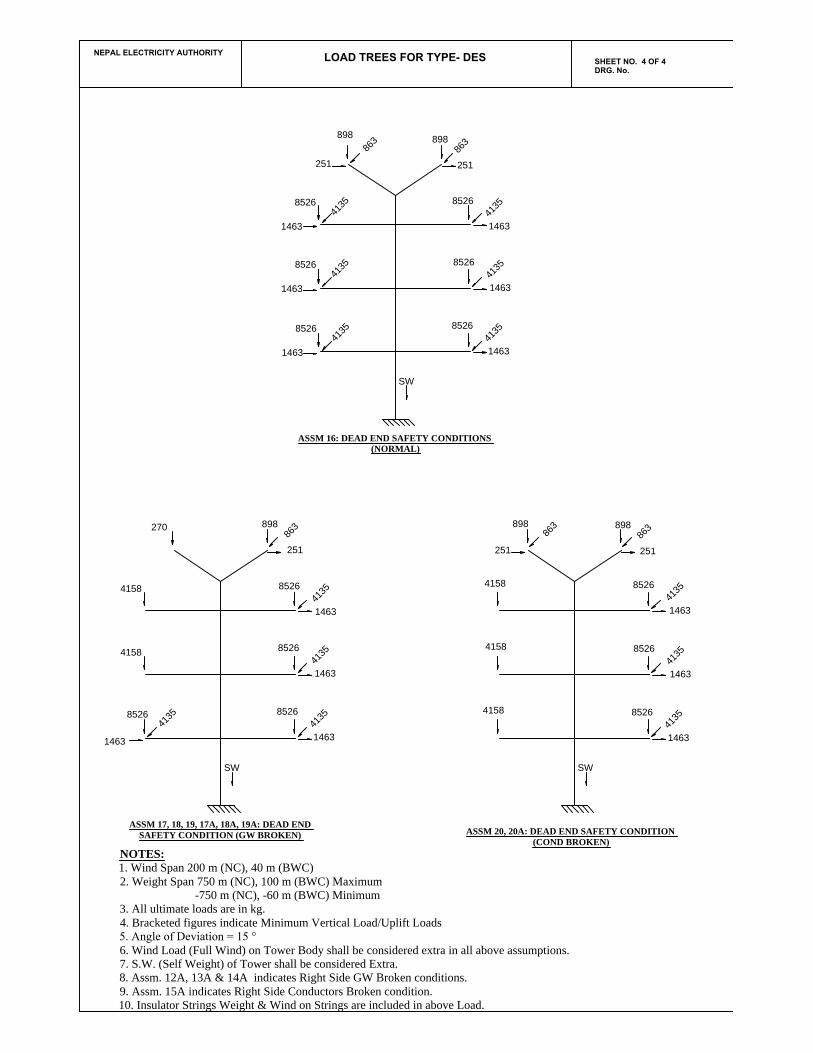
LOAD TREES FOR TYPE- DES
ASSM 20, 20A: DEAD END SAFETY CONDITION(COND BROKEN)
ASSM 17, 18, 19, 17A, 18A, 19A: DEAD ENDSAFETY CONDITION (GW BROKEN)
SW SW
270
4158
ASSM 16: DEAD END SAFETY CONDITIONS(NORMAL)
SW
8526
1463
4
1
3
5
4158
898
8
6
3
251
4158
4158
4158
8
6
3
898
251
8526
1463
4
1
3
5
8526
1463
4
1
3
5
1463
4
1
3
5
8526
1463
4
1
3
5
8526
1463
4
1
3
5
8526
8
6
3
898
251
1463
4
1
3
5
8526
1463
4
1
3
5
8526
1463
4
1
3
5
8526
8526
4
1
3
5
1463
8
6
3
898
251
1463
4
1
3
5
8526
1463
4
1
3
5
8526
1463
4
1
3
5
8526
898
8
6
3251
NOTES:1. Wind Span 200 m (NC), 40 m (BWC)2. Weight Span 750 m (NC), 100 m (BWC) Maximum -750 m (NC), -60 m (BWC) Minimum3. All ultimate loads are in kg.4. Bracketed figures indicate Minimum Vertical Load/Uplift Loads5. Angle of Deviation = 15 °6. Wind Load (Full Wind) on Tower Body shall be considered extra in all above assumptions.7. S.W. (Self Weight) of Tower shall be considered Extra.8. Assm. 12A, 13A & 14A indicates Right Side GW Broken conditions.9. Assm. 15A indicates Right Side Conductors Broken condition.10. Insulator Strings Weight & Wind on Strings are included in above Load.
NEPAL ELECTRICITY AUTHORITY
SHEET NO. 4 OF 4DRG. No.