neoloch inquisitor core core kit assembly instructions.… · neoloch inquisitor core assembly...
TRANSCRIPT

NeoLoch Inquisitor Core
Assembly Instructions(9/3/2015)
Your kit should contain the following items. If you find a part missing, please contactNeoLoch for a replacement.
Kit contents:• 1 – PCB• 1 – 2.1mm DC Power Jack• 1 – 4.7K Potentiometer • 1 – 3 Pin Straight Header• 1 – Jumper• 1 – 11V Zener Diode• 1 – 12V Voltage Reg. TO-220• 1 – 5V Voltage Reg. TO-220• 2 – 0.33uF Capacitors• 2 – 1/4” Screws & Nuts• 1 – 50 Pin Card Edge Socket• 1 – 40 ZIF Socket• 1 – 28 Pin Socket• 1 – MCP23017 Port Expander.• 1 – LCD Screen• 1 – 16 Pin Straight Header• 1 – 0.1uF Capacitors• 1 – 1M Ohm Resistor 1/4th W• 4 – 1K Ohm Resistors 1/4th W• 6 – 10K Ohm Resistors 1/4th W• 1 – 3.3K Ohm Resistors 1/4th W• 1 – 15K Ohm Resistors 1/4th W• 1 – 20K Ohm Resistors 1/4th W• 3 – 390 Ohm Resistor 1/8th W• 2 – 2x5 Red LED• 1 – 2x5 Red / Green LED• 1 – Power Switch• 5 – Push Button Switches • 1 – Quick Reference Guide• 4 – Rubber bumpers.
2013 NeoLoch, LLC 1

Assembly Instructions
When assembling the board you'll notice thatsome pads are square while the others are round.The square pad is a pin 1 indicator and will aid inthe board's assembly.
You'll need to trim excess leads from each partafter soldering is complete.
Most of the board will progress from the lowestprofile parts to the highest. So we'll begin withinstalling the resistors.
Step 1: Solder the three 1/8th Watt 390Ω (orange,white, brown) resistors into R13, R17 and R18.
Step 2: Solder the six 10KΩ (brown, black,orange) resistors into R3, R6, R7, R10, R11 andR12.
Step 3: Solder the four 1KΩ (Brown, Black, red)resistors into R1, R14, R15 and R16.
2013 NeoLoch, LLC 2

Step 4: • Solder the 3.3KΩ (orange, orange, red)
resistor into R2.• Solder the 15KΩ (brown, green, orange)
resistor into R4.• Solder the 20KΩ (red, black, orange)
resistor into R5.• Solder the 1MΩ (brown, black, green)
resistor into R9,
• Solder the Zener Diode into D1.
2013 NeoLoch, LLC 3

Step 5: Solder the 7805 5V regulator into U3. Besure to pass the bolt from underneath and securewith a nut. This helps keep the profile on thebottom of the board lower.
Step 6: Solder the 7812 12V regulator into U2.Be sure to pass the bolt from underneath andsecure with a nut. This helps keep the profile onthe bottom of the board lower.
Step 7: Solder the 28 pin socket to U1, and makesure the dimple is facing the 1K Ohm resistor.
2013 NeoLoch, LLC 4

Step 8: • Solder in the potentiometer into R8, this
part will be used to control the contrast onthe LCD screen.
• Solder the 2.1mm DC power jack into J1.• Solder the 3 pin straight header into JP1.• Push the jumper into the appropriate
position for the type of power supply youare using.
Step 9: Solder one of the 0.33uF capacitors intoC1. The longer lead goes into the whole with the+ sign (square pad).
Step 10: Solder the other 0.33uF capacitor into C3. The longer lead goes into the whole with the + sign (square pad).
Step 11: Solder the power switch into S6.
2013 NeoLoch, LLC 5
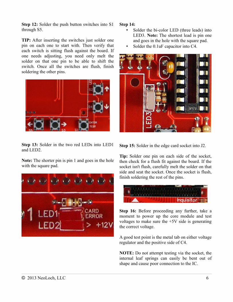
Step 12: Solder the push button switches into S1through S5.
TIP: After inserting the switches just solder onepin on each one to start with. Then verify thateach switch is sitting flush against the board. Ifone needs adjusting, you need only melt thesolder on that one pin to be able to shift theswitch. Once all the switches are flush, finishsoldering the other pins.
Step 13: Solder in the two red LEDs into LED1and LED2.
Note: The shorter pin is pin 1 and goes in the holewith the square pad.
Step 14: • Solder the bi-color LED (three leads) into
LED3. Note: The shortest lead is pin oneand goes in the hole with the square pad.
• Solder the 0.1uF capacitor into C4.
Step 15: Solder in the edge card socket into J2.
Tip: Solder one pin on each side of the socket,then check for a flush fit against the board. If thesocket isn't flush, carefully melt the solder on thatside and seat the socket. Once the socket is flush,finish soldering the rest of the pins.
Step 16: Before proceeding any further, take amoment to power up the core module and testvoltages to make sure the +5V side is generatingthe correct voltage.
A good test point is the metal tab on either voltageregulator and the positive side of C4.
NOTE: Do not attempt testing via the socket, theinternal leaf springs can easily be bent out ofshape and cause poor connection to the IC.
2013 NeoLoch, LLC 6
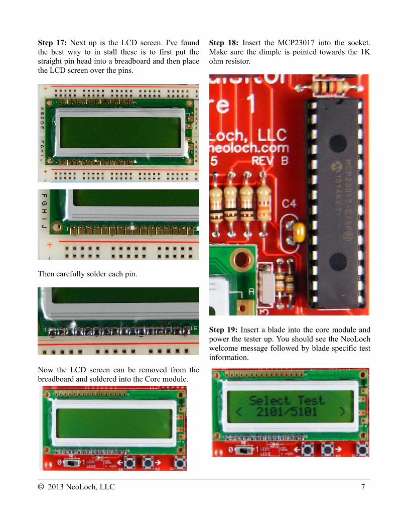
Step 17: Next up is the LCD screen. I've foundthe best way to in stall these is to first put thestraight pin head into a breadboard and then placethe LCD screen over the pins.
Then carefully solder each pin.
Now the LCD screen can be removed from thebreadboard and soldered into the Core module.
Step 18: Insert the MCP23017 into the socket.Make sure the dimple is pointed towards the 1Kohm resistor.
Step 19: Insert a blade into the core module andpower the tester up. You should see the NeoLochwelcome message followed by blade specific testinformation.
2013 NeoLoch, LLC 7

If the LCD screen is blank then the contrast needsadjusting. Using a small screwdriver, slowlyrotate the potentiometer counter clockwise untiltext appears on the LCD screen.
If you turn the potentiometer all the way andnothing is showing up on the screen thensomething is wrong. Power down the tester anddouble check all your solder joints. If the testerstill isn't working, then proceed to thetroubleshooting section.
Step 20: Solder in the ZIF socket.
Step 21: If so desired, add the rubber bumpers toyour tester.
Troubleshooting
if your board doesn't work, try these solutions before contacting NeoLoch for assistance.
Also, please keep in mind that the core module will not operate without a blade inserted.
LCD Screen is Blank:◦ Adjust the contrast using the
potentiometer .◦ Check and make sure all the LCD
connections are properly solderedto the main PCB.
Tester Fails to Test Correctly:
1. Check to make sure that the ground andpower pin are being supplied correctly.Check for proper voltage supply.
2. Check all the solder joints to make surenothing was missed. If even a single pinisn't soldered correctly on the ZIF socketor the 40 pin socket, the tester won't workcorrectly.
3. If the tester still doesn't work, it's possibleyour PIC isn't programmed. Though wemake every effort to make sure theprocessor is programmed before leaving, amistake does happen from time to time. Ifyou have access to a PICkit, tryprogramming the PIC with the currentfirmware available from our website. Youcan find it on the information page forLCD RAM tester . If you don't haveaccess to a programmer, then contactNeoLoch directly for further assistance.
www.neoloch.com772-318-4333
Skype: NeoLoch
2013 NeoLoch, LLC 8