nelson irrigation corp. 848 airport rd. walla walla, wa ... · pdf filecalculating the common...
TRANSCRIPT
Nelson Irrigation Corp. 848 Airport Rd. Walla Walla, WA 99362-2271 USA Tel: 509.525.7660 Fax: 509.525.7907 E-mail: [email protected] Web site: www.nelsonirrigation.com
800SVRM-7 5/04
20
20.3
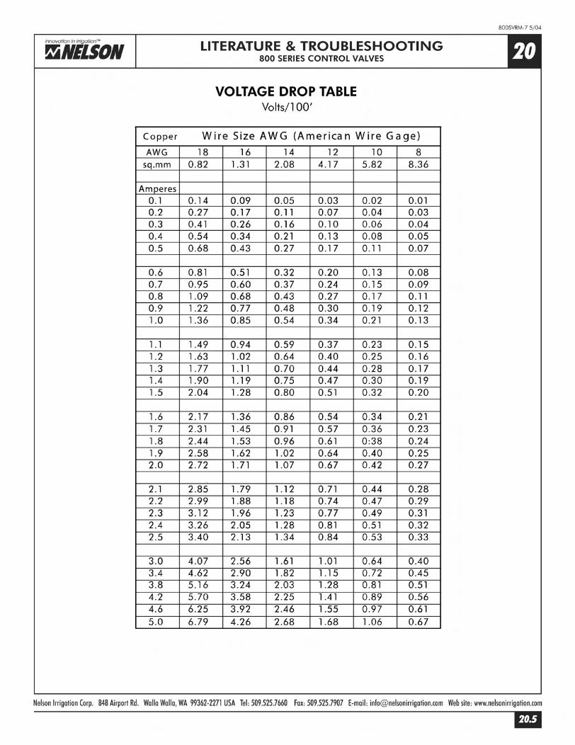
LITERATURE & TROUBLESHOOTING800 SERIES CONTROL VALVES
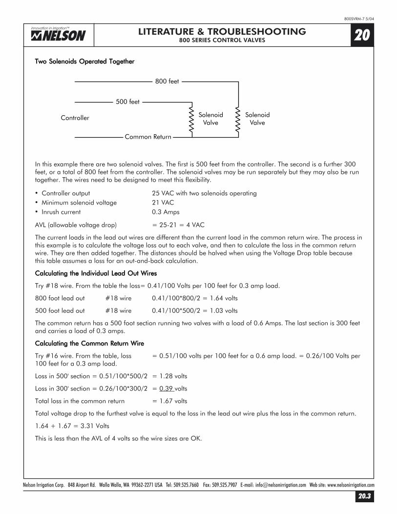
Two Solenoids Operated TogetherTwo Solenoids Operated TogetherTwo Solenoids Operated TogetherTwo Solenoids Operated TogetherTwo Solenoids Operated Together
In this example there are two solenoid valves. The first is 500 feet from the controller. The second is a further 300feet, or a total of 800 feet from the controller. The solenoid valves may be run separately but they may also be runtogether. The wires need to be designed to meet this flexibility.
� Controller output 25 VAC with two solenoids operating� Minimum solenoid voltage 21 VAC� Inrush current 0.3 Amps
AVL (allowable voltage drop) = 25-21 = 4 VAC
The current loads in the lead out wires are different than the current load in the common return wire. The process inthis example is to calculate the voltage loss out to each valve, and then to calculate the loss in the common returnwire. They are then added together. The distances should be halved when using the Voltage Drop table becausethis table assumes a loss for an out-and-back calculation.
Calculating the Individual Lead Out WiresCalculating the Individual Lead Out WiresCalculating the Individual Lead Out WiresCalculating the Individual Lead Out WiresCalculating the Individual Lead Out Wires
Try #18 wire. From the table the loss= 0.41/100 Volts per 100 feet for 0.3 amp load.
800 foot lead out #18 wire 0.41/100*800/2 = 1.64 volts
500 foot lead out #18 wire 0.41/100*500/2 = 1.03 volts
The common return has a 500 foot section running two valves with a load of 0.6 Amps. The last section is 300 feetand carries a load of 0.3 amps.
Calculating the Common Return WireCalculating the Common Return WireCalculating the Common Return WireCalculating the Common Return WireCalculating the Common Return Wire
Try #16 wire. From the table, loss = 0.51/100 volts per 100 feet for a 0.6 amp load. = 0.26/100 Volts per100 feet for a 0.3 amp load.
Loss in 500' section = 0.51/100*500/2 = 1.28 volts
Loss in 300' section = 0.26/100*300/2 = 0.39 volts
Total loss in the common return = 1.67 volts
Total voltage drop to the furthest valve is equal to the loss in the lead out wire plus the loss in the common return.
1.64 + 1.67 = 3.31 Volts
This is less than the AVL of 4 volts so the wire sizes are OK.
Controller SolenoidValve
Common Return
SolenoidValve
500 feet
800 feet

Nelson Irrigation Corp. 848 Airport Rd. Walla Walla, WA 99362-2271 USA Tel: 509.525.7660 Fax: 509.525.7907 E-mail: [email protected] Web site: www.nelsonirrigation.com
20.4
800SVRM-7 5/04
20LITERATURE & TROUBLESHOOTING800 SERIES CONTROL VALVES
Installation Specification ExampleInstallation Specification ExampleInstallation Specification ExampleInstallation Specification ExampleInstallation Specification ExampleInstall electric control wire in the pipe trenches wherever possible. Place wire in the trench under the pipe. Install thewire with slack to allow for thermal expansion and contraction. Expansion joints in the wire may be provided at 200foot intervals by making 5-6 turns of the wire around a piece of 1/2" pipe instead of slack. Where it is necessary torun wire in a separate trench, provide a minimum cover of 24" (or follow the local code).
Provide sufficient slack at site connections, at remote control valves in control boxes, and at all wire splices to allowfor raising of the valve, or splice to the surface without disconnecting the wires when repair is required.
Make wire connections to remote control electric valves. No wire splices are allowed in the pipe trench. All splicesshould be located at a valve box.
Install an unconnected spare control wire from the controller through each intermediate control valve box. Enoughslack wire shall be left in each control valve box to allow its use if necessary. The spare wire should run from thecontroller to furthest valve position.