negative-pressure soft linear actuator with a mechanical
TRANSCRIPT
Negative-Pressure Soft LinearActuator with a Mechanical Advantage
The Harvard community has made thisarticle openly available. Please share howthis access benefits you. Your story matters
Citation Yang, Dian, Mohit S. Verma, Elton Lossner, Duncan Stothers, andGeorge M. Whitesides. 2016. Negative-Pressure Soft Linear Actuatorwith a Mechanical Advantage. Advanced Materials Technologies:1600164. Portico. doi:10.1002/admt.201600164.
Published Version 10.1002/admt.201600164
Citable link http://nrs.harvard.edu/urn-3:HUL.InstRepos:30353768
Terms of Use This article was downloaded from Harvard University’s DASHrepository, and is made available under the terms and conditionsapplicable to Open Access Policy Articles, as set forth at http://nrs.harvard.edu/urn-3:HUL.InstRepos:dash.current.terms-of-use#OAP

1
DOI: 10.1002/((please add manuscript number))
Article type: Communication
Negative-Pressure Soft Linear Actuator with a Mechanical Advantage
Dian Yang, Mohit S. Verma, Elton Lossner, Duncan Stothers, and George M. Whitesides*
Dr. D. Yang, Dr. M. S. Verma, E. Lossner, D. Stothers, Prof. G. M. Whitesides
Department of Chemistry and Chemical Biology Harvard University, 12 Oxford Street,
Cambridge, MA 02138, USA
E-mail: [email protected]
Prof. G. M. Whitesides
Kavli Institute for Bionano Science & Technology Harvard University, 29 Oxford Street,
Cambridge, MA 02138, USA
Prof. G. M. Whitesides
Wyss Institute for Biologically Inspired Engineering Harvard University, 60 Oxford Street,
Cambridge, MA 02138, USA
D. Yang
School of Engineering and Applied Sciences Harvard University, 29 Oxford Street, Cambridge,
MA 02138, USA
Keywords: vacuum, soft actuators, pneumatic actuation, linear actuator, mechanical advantage.
2
Soft, linear actuators (those that generate motions in a straight line—for example, the
muscles of animals[1]) have emerged from evolution as the best solution for moving limbed
organisms such as vertebrates and arthropods (as well as many organisms without limbs, such as
mollusks, annelids, and jellyfish) in an unstructured environment. Their compliance enables
adaptive interactions with the environment, and non-damaging (if required) contact with one
another. At the same time, this compliance reduces the cost to the organism of precise controls
and feedback loops.[2, 3] Linear actuation is also particularly compatible with a limbed body-plan
in its geometric adaptability since this body-plan is often based on rigid or semi-rigid structural
elements (the skeleton), which move relative to one another by linear contraction of muscles
around fulcra (e.g. joints). Hard, human-engineered machines now often use the rotary motion of
electric motors, although pneumatic and hydraulic pistons (based on force generated by
expansion of hot gas, pressurized air, vacuum, or pressurized liquid), other actuators (e.g.
magnetic solenoids), and transducers of biomechanical forces (e.g. screw drivers) are also
important. A key characteristic of soft machines is that they can be made collaborative (e.g.
intrinsically safe in close proximity to humans).
Devices or systems that generate a mechanical advantage—levers, gears, chain drives,
block and tackles, and others—are useful in amplifying either force or displacement in hard
machines. Humans and other vertebrates also use hard levers—system of bones, articulated
joints, and tendons—to amplify the displacement that muscles generate (albeit at the cost of
reduced force)[1]. A device that generates a mechanical advantage—i.e. amplifies force—in a soft
system would expand the capabilities of soft robots and machines. This paper reports the first of
such devices. The compliance of pneumatic soft actuators allows them to distribute their stress
over large areas,[2] but it also means the pressure output of these systems is often limited by their
3
pressure input, and thus also by the mechanical characteristics—especially the Young’s
Modulus—of the material of which they are made.[4] A soft pneumatic actuator designed to
generate a mechanical advantage would help to overcome this limitation.
Our goal was to introduce mechanical advantage into a soft pneumatic actuator. Figure
1A is a conceptual picture summarizing this goal. Compared to lifting a weight (generating
𝑚𝑔∆ℎ work) directly using a pneumatic piston (supplying 𝑃∆𝑉 work), pulling a weight on a
slope increases the weight 𝑚 pulled per applied pressure 𝑃, while decreasing the height ∆ℎ per
volume change ∆𝑉. The objective here is to realize this mechanical advantage in a soft actuator
without using an external slope.
This paper demonstrates a new design of a soft linear actuator that generates a tunable
mechanical advantage. For simplicity, we call these structures “shear-mode vacuum-actuated
machines,” and abbreviate them with the acronym “shear-VAMs”. A shear-VAM comprises two
flexible but inextensible strips bridged by tilted parallel beams. These beams can be fabricated of
an elastomer, a composite of soft and rigid material, or rigid structures (trusses) that can pivot on
their ends; the system we have explained are of the first (elastomeric) class. The spaces between
the beams are sealed pneumatically with two thin elastomeric membranes, and thus form void
chambers within. These chambers are connected to a single external vacuum source (or, in more
complex devices, multiple independently controllable sources). Through a network of channels
embedded in the structure, a shear-VAM operates by reducing the pressure of void chambers in
an elastomeric structure to below that of atmospheric pressure (that is, to negative pressure, or
partial vacuum). When the chambers are evacuated, ambient atmospheric pressure compresses
the two inextensible strips together. The design—in which the beams bend more easily than they

4
compress—causes these beams to tilt further; this increase in tilt, in turn, causes the strips to
translate parallel to one another, and to generate force (see Figure 1B, Movie S1).
These structures, together with soft actuators that we (in the form of pneu-nets[5-9],
buckling actuators[10], and vacuum-actuated muscle-inspired pneumatic structures[4]) and others
(flexible microactuators[11], jamming grippers[12], dielectric elastomer-driven actuators[13, 14],
shape memory and cable-driven soft arms[15], etc.) have described, belong to a new class of
machines—soft machines[2, 16]—which are more collaborative, often more adaptive to irregular
targets[16], and sometimes simpler to control[16] than more familiar hard machines.
Among these soft pneumatic actuators, we refer to those powered by negative pressure
(vacuum) rather than positive pressure as vacuum-actuated machines (VAMs). These devices
allow a range of functions that can sometimes be difficult to achieve by their conventional
pressure-driven counterparts. Examples of VAMs include rotary actuators that combine vacuum
and reversible buckling of elastomeric beams as their mechanism of action (rotary-VAMs),[10]
and linear actuators (using the same mechanism) that mimic the performance—and many useful
functions—of human muscle (linear-VAMs).[4]
Vacuum-actuated machines (VAMs) such as shear-VAMs are safer around humans than
many “hard” actuators, and even ostensibly soft actuators that operate under high positive
pressure (e.g. McKibben actuators and many of their relatives[17]). Actuators powered by
pneumatics are also safer and less likely to fail than those powered by high voltages (e.g.
actuators made with dielectric elastomer—such as those explored by SRI[13, 14]—which can fail
by dielectric breakdown).
Experimental design of shear-VAMs. A design representative of a simple shear-VAM
consists of two flexible but inextensible strips (1.5 mm thick, 17 mm wide, and 10 mm apart)
5
bridged by four tilted parallel elastomeric beams (1.8 mm wide, 8.9 mm long, at 63° angle to the
strips, and spaced in 10 mm-intervals along the strips, in Figure 1C). We used a Nylon mesh
embedded in an elastomer—Ecoflex 00-30 (Young’s modulus E = 43 kPa), Dragon Skin 10
Slow (E = 153 kPa), or Elastosil M4601 (E = 520 kPa)—for the inextensible layer. We used the
same elastomer in the elastomeric beams in shear-VAMs. The empty spaces in between the
beams were converted into enclosed chambers by sealing (front and back) with thin membranes
made of the same elastomer (1 mm thick). The final structure comprises a pneumatic structure
with several chambers connected to a common source of negative pressure (e.g. vacuum, or
pressure less than the ambient pressure). The beams each had an opening in the middle (a 3 mm-
wide slit) such that the chambers were pneumatically connected. The chambers were further
connected to an external source of vacuum through a piece of tubing that pierces one of the
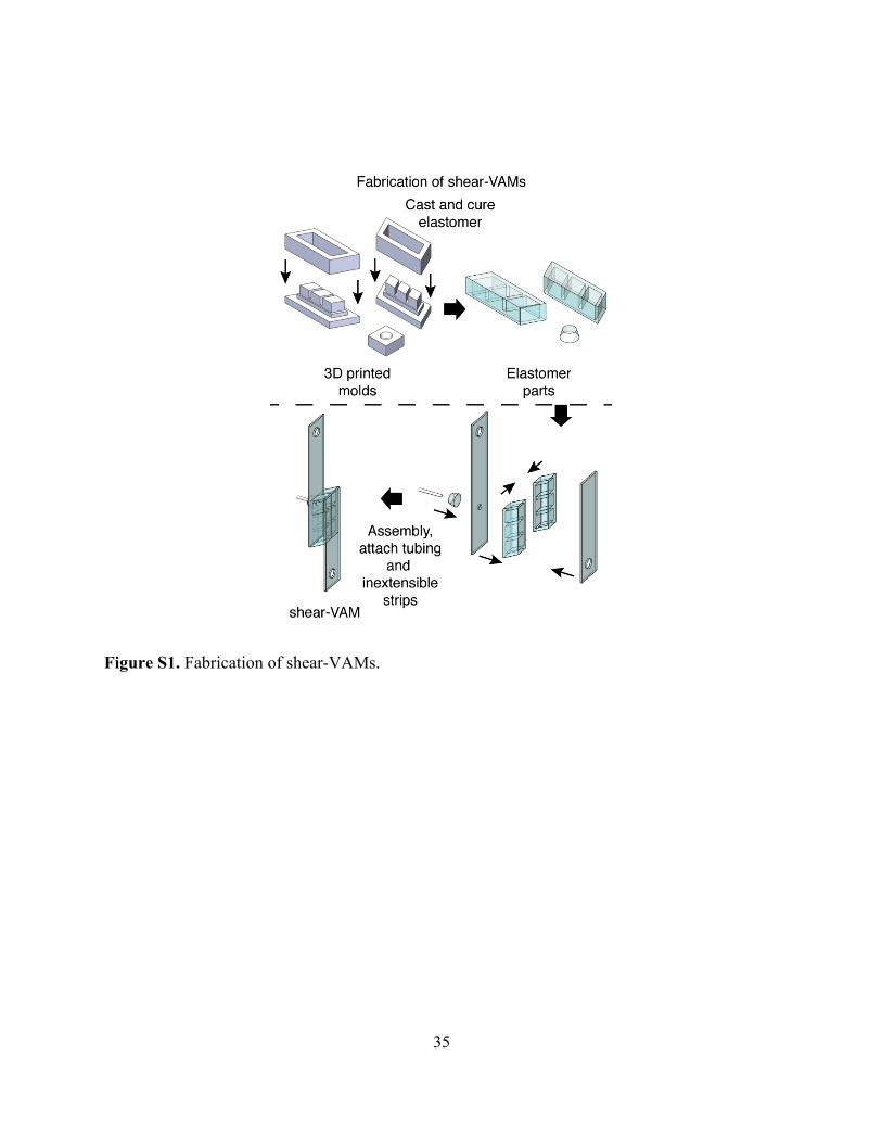
strips. (Figure S1 and the SI summarize details of fabrication.)
Characterizing the maximum force of actuation of shear-VAMs. A shear-VAM is similar
to a pneumatic or hydraulic piston, in that it works by converting an applied pneumatic pressure
∆𝑃 to an output force 𝐹. As we apply an increasing difference of pressure ∆𝑃 (as defined in
Equation 1) between that of the atmosphere external to the shear-VAM (𝑃𝑒𝑥𝑡), and that of the
partial vacuum inside it (𝑃𝑖𝑛𝑡), its void chambers deflate, and the two inextensible strips translate
relative to each other (as shown in Figure 1B, Movie S1).
∆𝑃=𝑃𝑒𝑥𝑡−𝑃𝑖𝑛𝑡 (1)
The two inextensible strips move until, at a critical difference of pressure ∆𝑃𝑐𝑟𝑖𝑡, the void
chambers collapse completely (or as completely as they can within the limits of the design) and
bring the actuator to a stop. The actuation of a shear-VAM results in a decrease in its length ∆ℎ
6
(also indicated in Figure 1). We defined this change in length ∆ℎ—effectively the relative
distance of translation between the two inextensible strips—to be the distance of actuation of a
shear-VAM. The actuation of a shear-VAM also applies a force 𝐹, as indicated in Figure 1B and
defined in Equation 2, where 𝑚 is the mass of a test object, and 𝑎 is the acceleration of that
object. We defined this force—the force that lifts and accelerates a load—to be the force of
actuation of a shear-VAM.
𝐹=𝑚𝑔+𝑚𝑎 (2)
The distance of actuation ∆ℎ (upon application of a difference of pressure ∆𝑃>∆𝑃𝑐𝑟𝑖𝑡) is
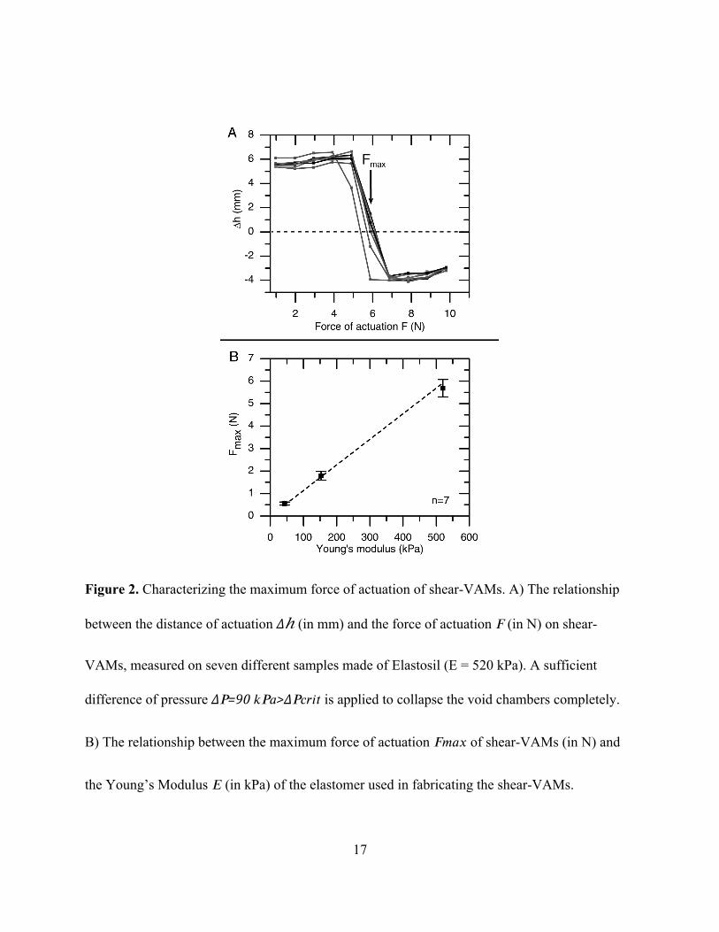
determined primarily by the geometry of the shear-VAM. Figure 2A shows that this distance ∆ℎ
stays roughly constant when various loading forces 𝐹 (in N, given by a hanging weight) are
applied to the shear-VAM while it actuates, as long as the loading force is less than a certain
maximum value 𝐹𝑚𝑎𝑥. We define 𝐹𝑚𝑎𝑥 to be the maximum force a shear-VAM of this
particular design can generate. For a load 𝐹 greater than 𝐹𝑚𝑎𝑥, the beams in the shear-VAM will
tilt in the opposite direction when the pressure ∆𝑃 is increased. In other words, the shear-VAM
lifts the weight for a distance of ∆ℎwhile 𝐹<𝐹𝑚𝑎𝑥 (i.e. produces a contraction), and it lowers the
weight for a distance of ∆ℎ′while 𝐹>𝐹𝑚𝑎𝑥 (i.e. produces an elongation). Figure S2 and Movie
S2 demonstrate this effect. The distance of elongation ∆ℎ′ is again roughly constant under
various constant loads 𝐹 greater than 𝐹𝑚𝑎𝑥, as ∆ℎ′ is also determined primarily by the geometry
of the shear-VAM.

7
The value of 𝐹𝑚𝑎𝑥 is dependent on various characteristics (geometry and materials
parameters) of the actuator. For example, for shear-VAMs that have the same geometry, ones
that are stiffer (i.e. made of elastomers with higher Young’s modulus) generate a higher force
upon actuation than those that are less stiff. Figure 2B shows that the maximum force of
actuation 𝐹𝑚𝑎𝑥 (in N) of a shear-VAM is proportional to the Young’s modulus 𝐸 (in Pa) of the
material of which it is fabricated (Equation 3):
𝐹𝑚𝑎𝑥=𝑘𝐸𝐿2, (3)
where 𝐿 is the length scale (in this case the length) of the shear-VAM, and 𝑘 is a dimensionless
constant. Figure S3 and Movies S3, S4 show that shear-VAMs with indistinguishable
geometries, but made in different materials, lift different weights.
This linear relationship (Equation 3) is confirmed theoretically though dimensional
considerations (a detailed theoretical analysis is in the SI). This scaling property (Equation 3)
allows one to construct shear-VAMs capable of generating a high force simply by choosing a
stiff elastomer during fabrication.
Characterizing the thermodynamic efficiency of shear-VAMs. The thermodynamic
efficiency of transduction of the pressure-volume work required to actuate shear-VAM into
mechanical (force × distance) work (e.g., lifting a weight) is primarily governed by the work
required to compress the elastomer. (Here, we only account for the pressure-volume work and
not the electrical energy required to operate the vacuum pump). The loss of energy due to
hysteresis is small relative to the work done to compress the elastomer (details are in the SI,
Figure S6). Our experimental data yield a thermodynamic efficiency of 35% for a distance of
actuation of ~4.7 mm at 200 g loading for the shear-VAM shown in Figure 1B. (For comparison,
8
the corresponding value of a human skeletal muscle is ~40%).[18] Repeated cycles of actuation
can lead to higher efficiency because the energy stored in the deformed, elastomeric components
can, in principle, be at least partially recovered during unloading. Another similar VAM—a
linear VAM[4]—has a similar potential for recovery of energy (the ability of soft actuators to
store and recover energy over repeated cycles of actuation has been reported in a number of
designs[18]).
Characterizing the mechanical advantage of shear-VAMs. We define the geometrical
parameters that characterize a shear-VAM (Figure 3A), where: 𝐿 is the length of the elastomeric
body of the actuator (i.e. the long dimension of the parallelepiped), 𝑎 is the length of the tilted
beams, 𝑏 is the width of the actuator (i.e. the third dimension of the parallelepiped), 𝛼 is the angle
between the strips and the beams, and 𝐴=𝐿∗𝑏 is the “lateral area” of the shear-VAM (the shaded
area in Figure 3A). The force of actuation is approximately given by Equation 4 (the SI includes
a theoretical derivation, and a comparison to conventional pneumatic/hydraulic systems).
𝐹=𝜂𝛼𝐴∆𝑃/tan𝛼, (4)
where𝜂𝛼 is the thermodynamic efficiency of the shear-VAM for an infinitesimal movement near
angle 𝛼. This value is approximately equal to the total thermodynamic efficiency of the shear-
VAM 𝜂.
Equation 4 indicates that we can increase the force of actuation of a shear-VAM by
increasing the lateral area of the shear-VAM 𝐴=𝐿𝑏 (Figure 3A). Assuming the pneumatic source
(not shown in Figure 3A) has a fixed working area (e.g. area of the diaphragm of a pump, or the
9
area of the plunger of a syringe) of 𝐴0, it generates a driving force of 𝐹𝑖𝑛=𝐴0∆𝑃. The shear-
VAM demonstrates a net mechanical advantage (MA) given by Equation 5.
𝑀𝐴=𝐹/𝐹𝑖𝑛=𝜂𝐴/(𝐴0tan𝛼) (5)
We note that the mechanical advantage of a shear-VAM can be, in principle, increased
indefinitely as we increase the lateral area 𝐴 (although the MA is, of course, limited by the
tensile strength of the strips). Figure 3B, C illustrate two cases where we increase either the
length 𝐿 or the width 𝑏 to increase the lateral area 𝐴, and consequently, to boost the force of
actuation 𝐹.
In particular, increasing the length 𝐿 allows a shear-VAM to increase its force of
actuation 𝐹 without increasing the apparent cross-sectional area 𝑏𝑎sin𝛼. This feature allows
shear-VAMs to have a mechanical advantage not only for force, but also for pressure. This
mechanical advantage (MAp) is defined as the ratio of the pressure that performs useful work to
the pressure that is applied (Equation 6).
𝑀𝐴𝑝=𝑃𝑜𝑢𝑡/𝑃𝑖𝑛=𝜂𝐿/(𝑎sin𝛼), (6)
where 𝑃𝑜𝑢𝑡=𝐹/(𝑏𝑎sin𝛼), and 𝑃𝑖𝑛=∆𝑃.
Equation 5 also indicates another source of mechanical advantage, which comes by
changing the angle 𝛼. Due to the inverse relationship between mechanical advantage 𝑀𝐴 and
tan𝛼, one can increase the mechanical advantage of any shear-VAM simply by reducing the
10
angle 𝛼. When the angle 𝛼 is small, the distance of actuation ∆ℎ per unit of change in angle ∆𝛼 is
also smaller—a tradeoff of smaller distance for larger force of actuation 𝐹.
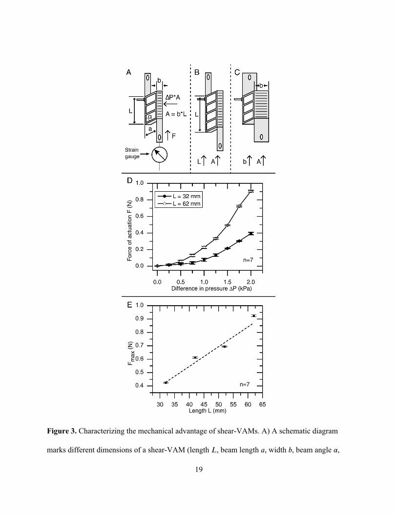
Figure 3D shows the relationship between the force of actuation 𝐹 of shear-VAMs of two
different lengths 𝐿=62𝑚𝑚 and 32𝑚𝑚 (each connected to a fixed strain gauge), and the
difference of pressure ∆𝑃 (in kPa) applied across the inside and outside (the ambient atmosphere)
of the void chambers of these shear-VAMs (see the SI and Figure S6 for details of this
measurement). At the same∆𝑃, the curves show a near doubling of force of actuation 𝐹, when
the length 𝐿 is doubled—a result consistent with Equation 4. Figure 3E shows that the maximum
force of actuation of shear-VAMs 𝐹𝑚𝑎𝑥 also increases with their length 𝐿, consistent with
Equation 4. The plot verifies that the relationship is linear. Error bars in Figure 3D, E were
measured from seven replicate measurements of the same sample (standard deviation of
measurements on different devices are larger than those from repeated measurements of the same
device, as shown in Figure S4, but can in principle be greatly reduced in machine-made devices
as opposed to handmade ones).
Parallel actuation and stackability of the shear-VAMs. Multiple shear-VAM units can be
positioned in parallel or in series and actuated together to generate more force or more distance
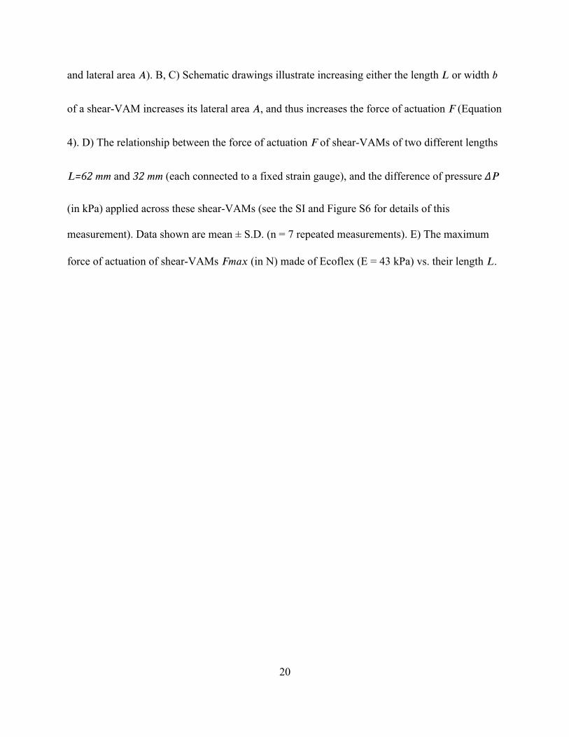
of actuation (see Figure 4 and Movies S5, S6). Figure 4A shows two shear-VAMs working in
parallel in a mirror configuration. This configuration generates about twice as much force (~2𝐹)
as a single shear-VAM of the same length 𝐿, but has about the same distance of actuation (~∆ℎ).
Figure 4B shows two shear-VAMs working in series. This configuration has about twice the

11
distance of actuation (~2∆ℎ) as a single shear-VAM of the same geometry, but generates about
the same force (~𝐹). These force or distance scaling relationships are universal to parallelizing or
stacking of any linear actuator. Shear-VAMs, in particular, are naturally fit for parallelization, as
their lateral areas remain flat during actuation (as shown in Figure 4A; the same is not true for
other pneumatic linear actuators such as McKibben actuators).
Using shear-VAMs in robots that locomote. The agonist-antagonist arrangement is useful
in the muscle of animals in enabling more effective movements. Since shear-VAMs resemble
biological muscle in that they are soft linear actuators, this arrangement can be borrowed in
making devices with shear-VAMs that move or locomote. Figure 5 and Movies S7, S8 show a
swimming device that uses a pair of shear-VAMs in an agonist-antagonist arrangement to drive
its paddle. The paddle moves either forward or backward when the corresponding shear-VAMs
actuate and pull the lever that is connected to the paddle. The paddle can pivot around its
connection backwards but not forward—this design helps to generate a hysteresis that is required
to propel the swimmer forward in water.
Conclusions. Shear-VAMs have three characteristics that are useful for making soft
machines. i) They provide a tunable mechanical advantage. ii) They can be easily used in series
or in parallel. iii) They contract rather than expand in volume on actuation. Shear-VAMs and
other soft pneumatic actuators are useful in supplementing more familiar hard machines with the
following advantages: i) increased safety in use around humans or animals, and non-damaging
interactions with delicate objects; ii) low cost of fabrication; iii) light weight and low density (the
actuating fluid is air, and the elastomers we use have densities around ~1 g/cm3).
A shear-VAM is a soft linear actuator that works by converting the pneumatic pressure
applied perpendicular to its inextensible lateral surfaces to a force parallel to them via tilted
12
elastomeric beams. It provides a mechanical advantage (that is, magnification) in terms of both
force and pressure relative to the input. It does so by increasing its length (for both force and
pressure) or width (for only force). The design of shear-VAM provides a new tool for making
biomimetic and/or functional soft machines. Shear-VAMs could, in particular, be useful for
generating high forces or generating reasonable forces with a small input pressure in a soft
structure.
Supporting Information
Supporting Information is available from the Wiley Online Library or from the author.
Acknowledgments
DY’s work on biomimetic design was funded by a subcontract from Northwestern University
under DOE award number DE-SC0000989. Work on mechanics and characterizations of the
actuator were funded by the DOE, Division of Materials Sciences and Engineering, grant number
ER45852. MSV is funded by the Banting Postdoctoral Fellowship from the Government of
Canada.
Received: ((will be filled in by the editorial staff))
Revised: ((will be filled in by the editorial staff))
Published online: ((will be filled in by the editorial staff))
[1] S. Vogel, Prime Mover: a Natural History of Muscle, WW Norton & Company: New
York, 2003.
13
[2] S. Kim, C. Laschi, B. Trimmer, Trends Biotechnol. 2013, 31, 287.
[3] C. C. Kemp, A. Edsinger, E. Torres-Jara, IEEE Robotics and Automation Magazine 2007,
14, 20.
[4] D. Yang, M. S. Verma, J.-H. So, B. Mosadegh, B. Lee, F. Khashai, E. Lossner, Z. Suo,
G. M. Whitesides, Adv. Mater. Technol. 2016, 1.
[5] F. Ilievski, A. D. Mazzeo, R. F. Shepherd, X. Chen, G. M. Whitesides, Angew. Chem. Int.
Ed. 2011, 123, 1930.
[6] R. F. Shepherd, A. A. Stokes, J. Freake, J. Barber, P. W. Snyder, A. D. Mazzeo, L.
Cademartiri, S. A. Morin, G. M. Whitesides, Angew. Chem. 2013, 125, 2964.
[7] B. Mosadegh, P. Polygerinos, C. Keplinger, S. Wennstedt, R. F. Shepherd, U. Gupta, J.
Shim, K. Bertoldi, C. J. Walsh, G. M. Whitesides, Adv. Funct. Mater. 2014, 24, 2163.
[8] R. V. Martinez, J. L. Branch, C. R. Fish, L. Jin, R. F. Shepherd, R. Nunes, Z. Suo, G. M.
Whitesides, Adv. Mater. 2013, 25, 205.
[9] R. V. Martinez, C. R. Fish, X. Chen, G. M. Whitesides, Adv. Funct. Mater. 2012, 22,
1376.
[10] D. Yang, B. Mosadegh, A. Ainla, B. Lee, F. Khashai, Z. Suo, K. Bertoldi, G. M.
Whitesides, Adv. Mater. 2015, 27, 6323.
[11] K. Suzumori, S. Iikura, H. Tanaka, Proc. IEEE Int. Conf. Rob. Autom. 1991, 204.
[12] E. Brown, N. Rodenberg, J. Amend, A. Mozeika, E. Steltz, M. R. Zakin, H. Lipson, H.
M. Jaeger, Proc. Natl. Acad. Sci. U.S.A. 2010, 107, 18809.
[13] G. Kovacs, L. Düring, S. Michel, G. Terrasi, Sens. Actuator A-Phys. 2009, 155, 299.
[14] Q. Pei, M. A. Rosenthal, R. Pelrine, S. Stanford, R. D. Kornbluh, Smart Struct. Mater.
2003, 281.
14
[15] C. Laschi, M. Cianchetti, B. Mazzolai, L. Margheri, M. Follador, P. Dario, Advanced
Robotics 2012, 26, 709.
[16] D. Rus, M. T. Tolley, Nature 2015, 521, 467.
[17] F. Daerden, D. Lefeber, Eur. J. Mech. Environ. Eng. 2002, 47, 11.
[18] J. D. Madden, N. A. Vandesteeg, P. A. Anquetil, P. G. Madden, A. Takshi, R. Z. Pytel, S.
R. Lafontaine, P. A. Wieringa, I. W. Hunter, IEEE J. Ocean. Eng. 2004, 29, 706.

15
Figure 1. Schematic description of a shear-mode vacuum-actuated machine (shear-VAM). A)
An example of mechanical advantage in pneumatic actuation (ignoring effects of friction). B)
Mechanism of motion of a shear-VAM. A shear-VAM consists of two flexible but inextensible

16
strips bridged by tilted parallel elastomeric beams, with the closed chambers connected
pneumatically to a source of vacuum. When the chambers are evacuated, the two strips come
together, while the beams tilt further and push the strips to move parallel to one another, and
generate a distance of actuation ∆ℎ and/or a force of actuation 𝐹 (depending on the loading
condition). C) Schematic representation of a shear-VAM.
17
Figure 2. Characterizing the maximum force of actuation of shear-VAMs. A) The relationship
between the distance of actuation ∆ℎ (in mm) and the force of actuation 𝐹 (in N) on shear-
VAMs, measured on seven different samples made of Elastosil (E = 520 kPa). A sufficient
difference of pressure ∆𝑃=90𝑘𝑃𝑎>∆𝑃𝑐𝑟𝑖𝑡 is applied to collapse the void chambers completely.
B) The relationship between the maximum force of actuation 𝐹𝑚𝑎𝑥 of shear-VAMs (in N) and
the Young’s Modulus 𝐸 (in kPa) of the elastomer used in fabricating the shear-VAMs.

18
19
Figure 3. Characterizing the mechanical advantage of shear-VAMs. A) A schematic diagram
marks different dimensions of a shear-VAM (length 𝐿, beam length 𝑎, width 𝑏, beam angle 𝛼,
20
and lateral area 𝐴). B, C) Schematic drawings illustrate increasing either the length𝐿 or width 𝑏
of a shear-VAM increases its lateral area 𝐴, and thus increases the force of actuation 𝐹 (Equation
4). D) The relationship between the force of actuation 𝐹 of shear-VAMs of two different lengths
𝐿=62𝑚𝑚 and 32𝑚𝑚 (each connected to a fixed strain gauge), and the difference of pressure ∆𝑃
(in kPa) applied across these shear-VAMs (see the SI and Figure S6 for details of this
measurement). Data shown are mean ± S.D. (n = 7 repeated measurements). E) The maximum
force of actuation of shear-VAMs 𝐹𝑚𝑎𝑥 (in N) made of Ecoflex (E = 43 kPa) vs. their length 𝐿.
21
Figure 4. Multiple shear-VAMs working in combination. A) Two shear-VAMs working in
parallel in a mirror configuration. This configuration generates about twice as much force
compared to a single shear-VAM of the same geometry, but has about the same distance of
actuation. B) Two shear-VAMs working in series. This configuration has about twice as much
distance of actuation as a single shear-VAM of the same geometry, but generates about the same
force.

22

23
Figure 5. Soft robot actuated with shear-VAMs. A) Two shear-VAMs in an agonist-antagonist
arrangement can drive a paddle back and forth. The paddle can pivot around its connection
backwards but not forward. This mechanism can be used in a soft machine that paddles. B) A
soft robotic swimmer with a paddle powered by two shear-VAMs in an agonist-antagonist
arrangement. Scale bars are 1 cm-long. A quarter coin in the water also marks the scale.

24
Soft linear actuators are useful for making collaborative machines (e.g. machines that interact
safely with people in continuous, transitory, intentional, and incidental contact) and in designing
biomimetic robots based on animals over a range of levels of evolutionary development. This
study demonstrates a new type of soft linear actuator that uses negative pressure (vacuum) for its
actuation. This actuator also acts as a device designed to generate a tunable mechanical
advantage—the ratio of the force that performs useful work to the force that is applied—in soft
materials. It expands the capabilities of soft robots and machines, and in particular, overcomes
one of the limitations of current soft pneumatic actuators—that is, the force they apply is limited
by the pressure used to actuate them.
Keywords
vacuum, soft actuators, pneumatic actuation, linear actuator, mechanical advantage
D. Yang, M. S. Verma, E. Lossner, D. Stothers, and G. M. Whitesides*
Negative-Pressure Soft Linear Actuator with a Mechanical Advantage
25
Copyright WILEY-VCH Verlag GmbH & Co. KGaA, 69469 Weinheim, Germany, 2013.
Supporting Information
Negative-Pressure Soft Linear Actuator with a Mechanical Advantage
Dian Yang, Mohit S. Verma, Ju-Hee So, Elton Lossner, Duncan Stothers, and George M.
Whitesides*
Fabrication of shear-VAMs
The elastomeric parts of shear-VAMs were created by replica molding (Figure S1). We
designed the molds using computer-aided design (CAD) (Solidworks) and fabricated them with
acrylonitrile butadiene styrene (ABS) plastic using a 3D printer (StrataSys Fortus 250mc).
Curing a silicone-based elastomer (Ecoflex 00-30, dragon skin 10 slow, or Elastosil M4601)
against the molds at room temperature (4 hours for Ecoflex 00-30, and 6 hours for dragon skin
10 slow and Elastosil M4601) produced two halves of the shear-VAMs. These two halves were
aligned and bonded together by applying uncured elastomer at their interface, prior to curing
once again at room temperature for the same amount of time.
The inextensible strips were fabricated by placing pieces of nylon mesh on top of an
acrylic plastic board, then pouring the corresponding elastomer over the mesh. A wooden stick
was used to smooth the top surface of the elastomer. The composite strip is then formed after

26
curing the elastomer in a 60 °C oven for 15 min. Two holes 6-mm in diameter are punched at the
end of each strip for fixation purpose. Another smaller 3.5-mm diameter hole is punched on one
of the two strips on a shear-VAM so that tubing can go through and transduce pneumatic
pressure. The body of shear-VAM and the two strips are assembled by applying the same
elastomer that they are made of as glue, and curing them at room temperature for 6 hours.
A conically shaped piece of the elastomer was bonded to the side of the actuator to
provide additional material that allowed tubing (Intramedic polyethylene tubing, ID 0.76mm) to
be securely attached to the structure. The conical piece was first pierced by a cannula. The tubing
was fed through the cannula, which was then removed to leave the tubing embedded in the shear-
VAM. The tubing was secured by elastic deformation of the elastomer, which, as the tubing
displaced some of its volume, reacted by applying pressure to close the hole surrounding the
tubing.
Why the Young’s modulus 𝑬 of the elastomeric material used to fabricate a shear-VAM is
proportional to is maximum force of actuation 𝑭𝒎𝒂𝒙
A similar analysis was described in our paper on linear-VAMs;[1] we have adapted the
analysis here. Consider the body of the shear-VAM. Since the inextensible strips are not under
substantial deformation during actuation, the two side-surfaces of the shear-VAM that touch the
inextensible strip can be considered to be each in a fixed boundary condition relative to itself.
The two surfaces are, however, not fixed relative to each other. Due to the C2 symmetry of the
shear-VAM, the two surfaces must move parallel to each other during actuation, and a shear
stress is applied during this actuation. Let 𝜏 be the shear stress due to the hanging weight—that
27
is, the load 𝐹 divided by the lateral-area of the undeformed actuator𝐴. And let 𝑠 be the shear
strain between the two surfaces—that is, the relative movement of the two strips ∆ℎ divided by
the length of the actuator 𝐿 (Equation S1). We regard an actuator as a thermodynamic system of
two independent variables that can independently change the state of the actuator—the difference
of pressure ∆𝑃 and the loading stress 𝜏. To a good approximation, the elastomer is
incompressible. Hence the state of the actuator depends on difference of pressure ∆𝑃, but not on
the absolute pressures inside and outside the actuator. Since the experiment is insensitive to
small change in temperature, we do not list temperature as a variable. Using the neo-Hookean
model, we may obtain Equation S2 on the basis of dimensional considerations:
𝑠=∆ℎ/𝐿 (S1)
𝑠=𝑔(∆𝑃/𝐸,𝜏/𝐸), (S2)
where 𝑔 is a function of two variables and𝐸 is the Young’s modulus of the elastomeric material.
If we make two actuators with indistinguishable geometric features, but of materials with
different Young’s moduli, we can plot 𝑠 as a function of ∆𝑃/𝐸 and 𝜏/𝐸. The two surfaces will
fall on top of each other.
Notice that according to Equation S2, if one increases 𝐸, ∆𝑃, and 𝜏 by a common factor 𝑘, one
obtains the same strain 𝑠. Assuming 𝐸, ∆𝑃, and 𝜏 are increased to 𝐸′=𝑘𝐸, ∆𝑃′=𝑘∆𝑃, and 𝜏′=𝑘𝜏,
we have relationship S3, where if Equation S2 describes a shear-VAM made of an elastomer of

28
modulus 𝐸 then Equation S4 must describe a shear-VAM of indistinguishable geometry, but
made of an elastomer of modulus 𝐸′.
𝜏/𝐸=𝜏′/𝐸′ (S3)
𝑠=𝑔(∆𝑃′/𝐸′,𝜏′/𝐸′), (S4)
We note that a shear-VAM of modulus 𝐸 can lift weight𝐹=𝜏𝐴 only if the absolute value of
𝑠(∆𝑃) monotonically increases with ∆𝑃; note also that Equation S2 and S4 as a function of ∆𝑃
must be simultaneously monotonically increasing, if one of them is so. Therefore a shear-VAM
of modulus 𝐸 can lift weight𝐹=𝜏𝐴 if and only if a shear-VAM of modulus 𝐸′ can lift weight
𝐹′=𝜏′𝐴. In other words, the Young’s modulus 𝐸 of the elastomeric material used to fabricate a
shear-VAM is proportional to the maximum load it can lift.
Measurement of thermodynamic efficiency
We generated the pressure-volume hysteresis curves by pumping water (an
incompressible fluid) in and out of the shear-VAMs. The actuator was fully submerged in a 1-
gallon container of water. The hydraulic actuation, and measurement of volume was performed
with a syringe pump (Harvard Apparatus, PHD 2000), and the pressure measurement was
performed with a pressure sensor (Transducers Direct, TDH31) connected to the syringe pump
and the pressure transfer line (Figure S5). We fixated the actuator in a position that was
submerged fully in water. We filled the actuators with water by submerging them in the
container of water and deflating them several times until bubbles no longer emerged.

29
Within each test, we switched from deflation to inflation when the actuator had achieved
approximately complete contraction (about 3 mL change in volume). We chose the rate of
deflation and inflation to be 1 mL/min, which was sufficiently slow to achieve quasistatic
conditions. We repeated the deflation-inflation cycle seven times.
The fluid used for inflation/deflation (water) is effectively incompressible that we could
equate the volume decrease/increase of fluid in the syringe to that of the increase/decrease in the
volume of the channels in the shear-VAMs. The shear-VAMs required removal of 𝑉0=3mL of
water to achieve an actuation distance of ∆ℎ=~4.7𝑚𝑚, while lifting a 200 g test weight, and
while the applied differential pressure ramped up from 0 kPa to 15 kPa. We calculated the
thermodynamic efficiency 𝜂 by dividing “energy out” 𝐸out by “energy in” 𝐸in (Equation S5).
𝐸out was obtained by calculating the potential energy gain of lifting the weight (𝑚=200g was
the weight we used, and 𝑔 is the acceleration due to gravity) (Equation S6). 𝐸in was obtained by
integrating the differential pressure with respect to the change in volume (Equation S7). This
value is represented by the area under the P-V curve (Figure S5B).
𝜂=𝐸out/𝐸in. (S5)
𝐸out=𝑚𝑔∆ℎ. (S6)
𝐸in=0𝑉0𝑃(𝑉)𝑑𝑉. (S7)
Over a total of six runs, we obtained an efficiency of 𝜂=35%±1%. Note that the loss of energy
due to hysteresis was small compared to the work done by the syringe pump during actuation

30
(Figure S5B). The loss of efficiency was mainly due to the storage of elastic energy in the
elastomer, with a small contribution from hysteresis.
Approximate theoretical derivation of the force of actuation 𝑭
Due to conservation of energy, the generation of a higher force of actuation𝐹 of shear-
VAM (or of any other pneumatic actuators) requires the supply of a higher difference of pressure
∆𝑃. Although ∆𝑃 is limited to 1 atm under atmospheric pressure, we will show that the force of
actuation𝐹 of shear-VAMs increases linearly to the “lateral-area” of the strip 𝐴 under fixed ∆𝑃,
limited only by the tensile strength of the strips. We will show that, unique to shear-VAM, the
effective cross-sectional area of a shear-VAM does not necessarily increase as we increase 𝐴,
allowing the shear-VAM to generate a mechanical advantage.
We can derive (approximately) the force of actuation 𝐹 a shear-VAM produces for a
given difference of pressure ∆𝑃 (that is less than the critical difference of pressure of a shear-
VAM ∆𝑃𝑐𝑟𝑖𝑡) through an analysis of virtual work.[2] When a difference of pressure ∆𝑃 is applied,
the volume of the void chambers decreases, and the two strips move towards each other. Assume
an infinitesimal reduction of angle 𝛼 to 𝛼−𝛿𝛼 (in radian), while the “lateral-area” 𝐴 moves under
force ∆𝑃×𝐴, and the shear-VAM reduces its volume from 𝐴×a×sin𝛼 to 𝐴×a×sin𝛼−𝛿𝛼. The
pneumatics virtual work (pressure-volume work) done to the system is:
𝛿𝑊𝑖𝑛=∆𝑃×𝛿𝑉=∆𝑃×𝐴×a×sin𝛼−a×sin𝛼−𝛿𝛼
=∆𝑃×𝐴×a×cos𝛼×𝛿𝛼 (S8)
31
where 𝛿𝑉 is the change of overall volume of the elastomeric part of shear-VAM. Since the
elastomer is incompressible, 𝛿𝑉 is also equal to the volume of air pumped out of the void
chambers of the shear-VAM. In the meantime, the shear-VAM exerts force 𝐹 over a distance of
𝛿ℎ=(𝑎×cos𝛼−𝛿𝛼−𝑎×cos𝛼). The virtual work output (force-distance work) by the system to lift the
load is:
𝛿𝑊𝑜𝑢𝑡=𝐹×𝛿ℎ=𝐹×(𝑎×cos𝛼−𝛿𝛼−𝑎×cos𝛼)
=𝐹×a×sin𝛼×𝛿𝛼 (S9)
Dividing Equation S9 by Equation S8, we obtain:
𝜂𝛼=𝛿𝑊𝑜𝑢𝑡/𝛿𝑊𝑖𝑛=𝐹×tan𝛼/(∆𝑃×𝐴) (S10)
where 𝜂𝛼 is the efficiency of the shear-VAM near angle 𝛼, defined as the ratio between work out
𝛿𝑊𝑜𝑢𝑡and work in 𝛿𝑊𝑖𝑛 (Equation S10). Since we know 𝛿𝑊𝑖𝑛=𝛿𝑊𝑜𝑢𝑡+𝛿𝑊𝑙𝑜𝑠𝑡, where 𝛿𝑊𝑙𝑜𝑠𝑡
is the elastic and inelastic energy lost in compressing the elastomers, we know 𝜂𝛼<1.
Equivalently, Equation S10 can be written as a formula for the force of actuation 𝐹:
𝐹=𝜂𝛼×∆𝑃×𝐴/tan𝛼 (S11)
The efficiency 𝜂𝛼 comes primarily from the elastic loss in collapsing the chambers, and
should be, in principle, constant (for the same angle 𝛼) as long as the beam length 𝑎 and the beam
spacing (10 mm in this design) are fixed. This efficiency 𝜂𝛼 is approximately equal to the
thermodynamic efficiency of the shear-VAM 𝜂. Using the data plotted in Figure 3D, the
32
efficiency 𝜂𝛼 in two shear-VAMs of different length 𝐿=62𝑚𝑚,32𝑚𝑚 can be calculated using
Equation S10: the efficiencies are about the same for the two different lengths 𝐿, at ~40% (at
∆𝑃≈2𝑘𝑃𝑎, 𝛼≈45°), and they are similar to the total thermodynamic efficiency of the shear-VAM
(~35%).
In this derivation, we assumed the contribution of out-of-plane deformation of the
inextensible strips to ∆ℎ is negligible—this assumption is especially true if the strips are made of
materials with high stiffness. For more flexible strips, the ∆ℎ will be larger than our estimation
due to tilting of the elastomeric body at un-actuated state (Figure 4B shows an example of this
tilting), resulting in an under-estimation of 𝛿ℎ. We also assume that the deformation of the
elastomeric membranes is negligible. This assumption results in an over-estimation of change in
volume 𝛿𝑉 as a function of angle 𝛼. Overall, these assumptions results in an overestimation of 𝐹,
since:
𝐹×𝛿ℎ=𝜂×∆𝑃×𝛿𝑉 (S12)
This overestimation, however, doesn’t change the qualitative behavior of 𝐹. Thus we can
still use Equation S11 to study the scaling properties of 𝐹, which is the purpose of this
derivation.
Comparison of shear-VAMs to conventional pneumatic/hydraulic systems
Mechanical advantage is often present in ordinary pneumatic/hydraulic systems. In a
simple system with two cylinders (input cylinder with area A0 and output cylinder with area A),
the mechanical advantage MA = A/A0. There are two key differences between an ordinary

33
pneumatic system and shear-VAMs. i) The direction of force applied is perpendicular to the
surface in the ordinary system, while it is parallel for shear-VAMs. This difference in direction
implies that pressure-based mechanical advantage (Equation 6) can be achieved, which is not
possible in the ordinary system. ii) The mechanical advantage for shear-VAMs, in terms of
force, can be higher than that for the ordinary systems. Force generated by the ordinary system is
∆P × A, whereas force generated by shear-VAMs is given by Equation 4. Thus, for the same area
A, and pressure differential ∆P, the ratio of the force generated by shear-VAMs to the force
generated by ordinary system is η/tan(α). For the current design (with η ≈ 35%), shear-VAMs
can achieve greater mechanical advantage than ordinary systems for α < 20°.
Experimental procedure for measuring the relationship between the force of actuation 𝑭
and the difference of pressure ∆𝑷
Figure S6 shows a schematic diagram for the testing setup that measures relationship
between the force of actuation 𝐹 of shear-VAMs and the difference of pressure ∆𝑃 applied across
the inside and outside of the shear-VAMs. The bottom end of each shear-VAM is tied to a
weight placed on a scale to measure the force of actuation of the shear-VAM. The forces did not
exceed the weight and thus, the weight did not lift off the scale. The scale together with the
weight acts as a strain gauge to measure the force of actuation 𝐹 of the shear-VAMs.
We generated the difference of pressure ∆𝑃 (i.e. a partial vacuum) by pumping air out of
the actuator with a syringe connected to a syringe pump (Harvard Apparatus, PHD 2000). The
pressure measurement was performed with a pressure sensor (Honeywell ASDX005D44R)
connected to the syringe pump and the pressure transfer line (Figure S6). The voltage signal from
the pressure sensor is received through a DAQ (NI USB-6210) and read with National

34
InstrumentsTM LabVIEW. We slowly extracted air using the syringe pump at a rate of 2 mL/min
and recorded the force readings at predetermined values of pressure. We repeated the deflation-
inflation cycle seven times to obtain error bars for Figure 3D.
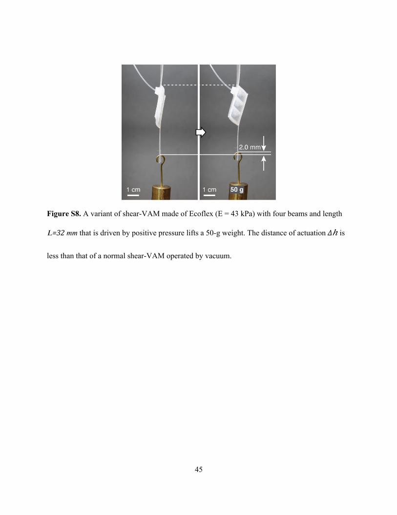
“Shear-VAMs” actuated with positive pressure
We can vary the design of a shear-VAM to generate an actuation stress by inflating the
structure rather than deflating it. Figure S8 and Movie S8 show a variant of shear-VAM made of
Ecoflex (E = 43 kPa) with four beams that is driven by positive pressure to lift a 50 g-weight.
This actuator is made based on a shear-VAM but the elastomeric body is glued in the opposite
direction to the strips so that the angle between the beams and the strips 𝛼<90° is now
𝛼′=180°−𝛼>90°. This configuration generates a smaller distance of actuation ∆ℎ than a normal
shear-VAM.
SI References
[1] D. Yang, M. S. Verma, J.-H. So, B. Mosadegh, B. Lee, F. Khashai, E. Lossner, Z. Suo,
G. M. Whitesides, Adv. Mater. Technol. 2016, 1.
[2] C. L. Dym, I. H. Shames, Solid Mechanics: A Variational Approach, Springer, 1973.
35
Figure S1. Fabrication of shear-VAMs.

36
Figure S2. A shear-VAM contracts or extends on actuation depending on the load. A) The shear-
VAM lifts the weight for a distance of ∆ℎ upon actuation while 𝐹<𝐹𝑚𝑎𝑥. B) The shear-VAM
lowers the weight for a distance of ∆ℎ′ upon actuation while 𝐹>𝐹𝑚𝑎𝑥. The difference of
pressure applied is Δ𝑃 = 90 kPa.

37
Figure S3. A shear-VAM fabricated from a stiffer elastomer can lift a heavier weight. A) A
shear-VAM made of Ecoflex (E = 43 kPa) with four beams lifts a 40 g-weight (Δ𝑃 = 90 kPa). B)
A shear-VAM of the same geometry but made of Elastosil (E = 520 kPa) lifts a 400 g-weight
(Δ𝑃 = 90 kPa).
38

39
Figure S4. The force of actuation 𝐹 of seven different shear-VAMs of length𝐿=32𝑚𝑚
(connected to a fixed strain gauge) vs. the difference of pressure ∆𝑃 (in kPa) applied across the
inside and outside of the shear-VAMs.

40
Figure S5. Experiment used to determine the thermodynamic efficiency of operation of a shear-
VAM. (A) Schematic describing the setup used for testing. (B) P-V curves of a shear-VAM
fabricated in Elastosil lifting a 500 g weight. The actuation curve is marked in black, and the
return curve is marked in red. The shaded area 𝑬𝐢𝐧 represents the fluidic energy input via the
syringe pump.
41
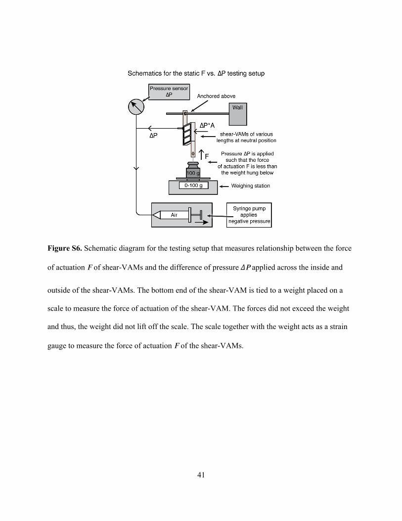
Figure S6. Schematic diagram for the testing setup that measures relationship between the force
of actuation 𝐹 of shear-VAMs and the difference of pressure ∆𝑃 applied across the inside and
outside of the shear-VAMs. The bottom end of the shear-VAM is tied to a weight placed on a
scale to measure the force of actuation of the shear-VAM. The forces did not exceed the weight
and thus, the weight did not lift off the scale. The scale together with the weight acts as a strain
gauge to measure the force of actuation 𝐹 of the shear-VAMs.
42

43
44
Figure S7. The maximum force of actuation of a shear-VAM 𝐹𝑚𝑎𝑥 (in Newtons) increases with
its length 𝐿. A series of shear-VAMs of different lengths is tested to lift an increasing series of
weights in 10 g-intervals (i.e. 10 g, 20 g, 30 g, etc.). The figure shows each of them lifting their
highest weight in the series. A) A shear-VAM made of Ecoflex (E = 43 kPa) with five beams and
length𝐿=42𝑚𝑚 lifts a 50 g-weight. B) A shear-VAM made of the same material but with six
beams and length𝐿=52𝑚𝑚 lifts a 60 g-weight. C) A shear-VAM of the made of the same
material but with seven beams and length𝐿=62𝑚𝑚 lifts an 80 g-weight.
45
Figure S8. A variant of shear-VAM made of Ecoflex (E = 43 kPa) with four beams and length
𝐿=32𝑚𝑚 that is driven by positive pressure lifts a 50-g weight. The distance of actuation ∆ℎ is
less than that of a normal shear-VAM operated by vacuum.

46
Supporting Movie Legends
Movie S1. A shear-VAM fabricated in Ecoflex (E = 43 kPa) performing an actuation. The inside
of the membrane is painted with a black marker to reveal the shape of the chamber more clearly.
A black outline is visible after the actuator contracts.
Movie S2. When a shear-VAM is actuated, it could either perform a contraction or elongation
depending on the load.
Movie S3. A shear-VAM fabricated in Ecoflex (E = 43 kPa) lifting a 40-g weight.
Movie S4. A shear-VAM fabricated in Elastosil (E = 520 kPa) lifting a 400-g weight.
Movie S5. Two shear-VAMs fabricated in Ecoflex (E = 43 kPa) in a parallel configuration lifting
about twice as much as one such shear-VAM, but the same distance.
Movie S6. Two shear-VAMs fabricated in Ecoflex (E = 43 kPa) in series configuration lifting
about the same weight as one such shear-VAM, but about twice the distance.
Movie S7. Two shear-VAMs in an agonist-antagonist configuration are able to drive a paddle
used for a toy boat.

47
Movie S8. A paddle driven by two shear-VAMs in an agonist-antagonist configuration is able to
move a toy boat in a water tank.
Movie S9. A shear-VAM where the beams are tilted in the opposite direction can be actuated
with positive pressure.