nebbinar: a tab professional’s wish list: equipment ... · has been a nebb certified professional...
TRANSCRIPT
0
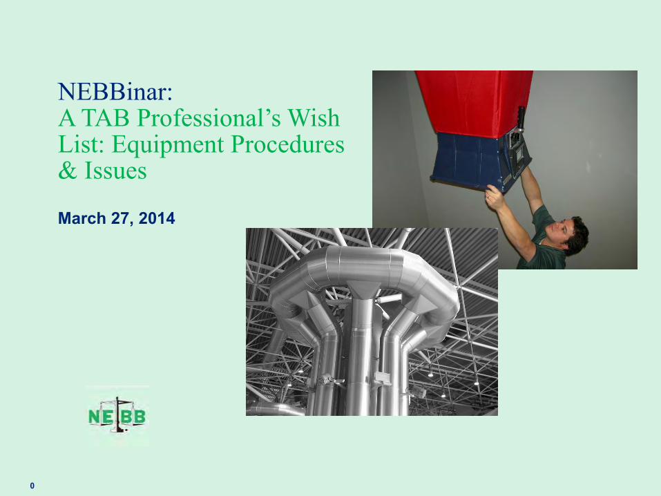
NEBBinar: A TAB Professional’s Wish List: Equipment Procedures & Issues
March 27, 2014

1
Moderator
Tom Hanlon NEBB’s TAB Committee
Tom has forty years of experience in refrigeration systems control system design, installation, start-up, project management, technical consultation, and systems commissioning. His level of experience allows him to act as an “Owner’s Representative” on commissioning, retro-commissioning and sustainability projects. Has worked as an application engineer and project manager for ten years with Johnson Controls; fifteen years as an independent NEBB Testing-Balancing Commissioning Agency; six years as project manager for Trane Arkansas and recently managed multiple commissioning and sustainability projects as a contract provider for TME Inc. Tom is currently Commissioning Project Manager with the Cromwell Firm, managing and executing multiple Commissioning and Retro-commissioning projects.

2
Speaker
Rodney Hinton is the VP of Palmetto Air & Water Balance, has been involved in the South Carolina Construction industry for over 30 years. His experience includes Air Barrier Testing, Mechanical Design, Mechanical Construction, Test & Balance, Commissioning and Retro Commissioning. He is a member of the NEBB Test, Adjust and Balancing Committee. He is a Member of ASHRAE. He has been a NEBB Certified professional since 1991 and has co-authored several standards regarding TAB and BET for NEBB.
Rodney Hinton NEBB’s TAB Committee

3
Speaker
Leonard Maiani joined NEBB as Technical Director in January 2014. He brings over 48 years of industry experience. He began his career in the Testing, Adjusting & Balancing business in Cleveland, Ohio 1n 1966. He then spent 15 years working in Houston, Texas as a Construction Administrator and TAB professional in various organizations. In 1989, he started Maiani Construction Services in 1989 in the Pacific Northwest and, after 27 years, turned the business over to his son and joined the NEBB staff.
Leonard Maiani NEBB’s Technical Director

4
Overview of Testing, Adjusting and Balancing
NEBB TAB Update: • New Procedural Standards-Update-Release • Instrument Consolidations • Enhanced equipment reporting
Equipment Procedures-Issues: • Fan Powered VAV-Series & Parallel • Energy Recovery-Heat Recovery Systems. Types, Procedures, Issues
Question and Answers
Agenda

5
Overview of Testing, Adjusting and Balancing
NEBB TAB Update: • New Procedural Standards-Update-Release • Instrument Consolidations • Enhanced equipment reporting
Equipment Procedures-Issues: • Fan Powered VAV-Series & Parallel • Energy Recovery-Heat Recovery Systems. Types, Procedures, Issues
Question and Answers
Agenda
6
NEBB TAB Procedural Standards Update
• Format Change: Shall, Should, May eliminated. Now Required
• New Procedural Standards-Update-Release

7
The NEBB Procedural Standards for Testing Adjusting
and Balancing of Environmental Systems establish a uniform and systematic set of criteria for the performance of the testing, adjusting and balancing of environmental or Heating, Ventilating and Air-conditioning (HVAC) systems.
Today’s buildings provide highly controlled, sustainable energy efficient indoor environments. These buildings include very sophisticated mechanical systems created by a team of skilled professionals. A key member of this team is the NEBB Test, Adjust, and Balance (TAB) Certified Firm.
NEBB TAB Procedural Standards (continued)

8
This Eighth Edition represents an update from past editions but remains divided into two distinct Parts: Standards and Procedures. These TAB Procedural Standards have been developed using language defined by “Required” as it relates to the standards and procedures described in this manual. It is important to note this wording throughout this manual and how it pertains to the NEBB standards and procedures. These standards and procedures are intended as the minimum NEBB requirements that a NEBB TAB Certified Firm must follow when performing Testing, Adjusting, and Balancing procedures. Contract documents may supersede the NEBB requirements. These TAB Procedural Standards have been carefully compiled and reviewed by the NEBB Technical Committees.
9
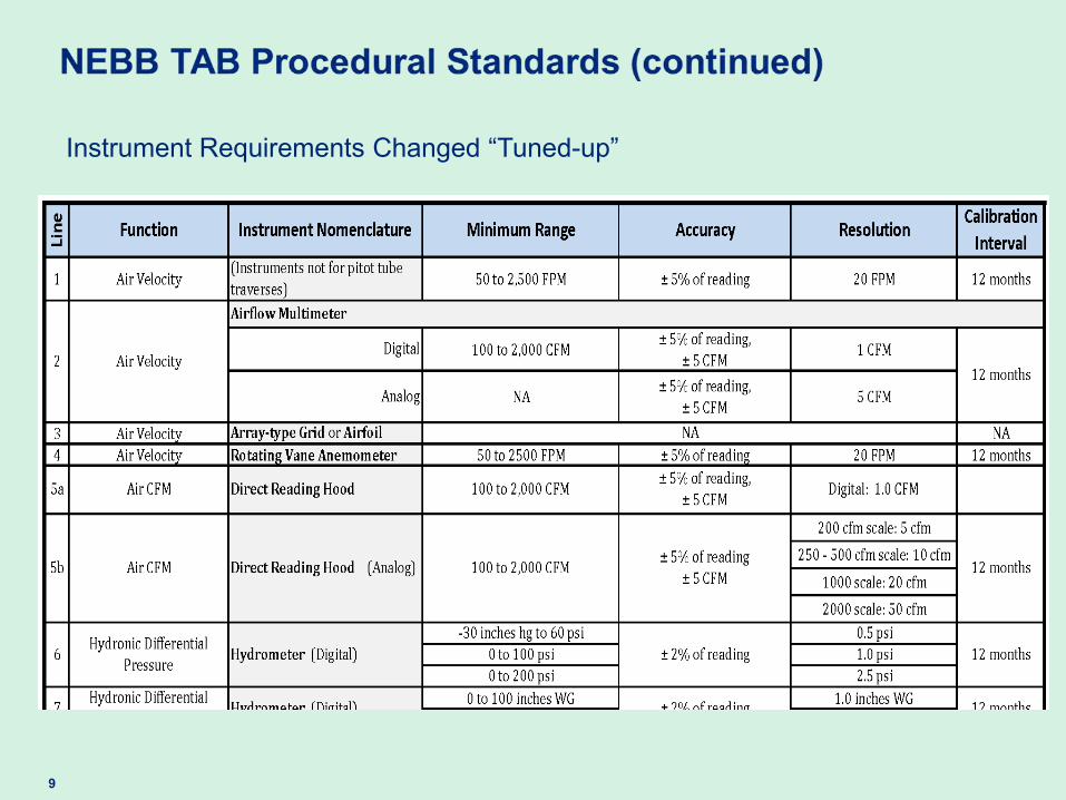
Instrument Requirements Changed “Tuned-up”

10
Enhanced Equipment Reporting-Example: Air Handling Unit (Unitary-Belt Driven)
Unit designation / Area Served
Unit type / arrangement / location
Manufacturer Model number Total design airflow Total outlet airflow Outside airflow
Fan rpm Fan motor HP (kW) Fan motor rpm Fan motor voltage Fan motor phase
Total SP / External SP
Design Data

11
Enhanced Equipment Reporting-Example: Air Handling Unit (Unitary-Belt Driven)
Unit serial number Supply airflow Return airflow Outside airflow. Minimum, Maximum External suction SP External discharge SP External SP
Fan motor manufacturer Fan motor frame
Fan motor HP (kW) Fan motor rpm Fan motor operating HZ, Static Pressure Setpoint Fan motor calculated BHP (kW)
Fan motor rated voltage Fan motor rated amperage
Fan motor service factor Fan motor operating voltages Fan motor operating amperages
Sheave manufacturer Motor sheave OD / bore Fan sheave OD / bore
Adjustable sheave operating diameter Sheave centerline distance
Fan rpm
Belt manufacturer Number belts / size
Number filters / type / size
All coil and filter pressure drops (P)
Actual-Field Data
12
Overview of Testing, Adjusting and Balancing
NEBB TAB Update: • New Procedural Standards-Update-Release • Instrument Consolidations • Enhanced equipment reporting
Equipment Procedures-Issues: • Fan Powered VAV-Series & Parallel • Energy Recovery-Heat Recovery Systems. Types, Procedures, Issues
Question and Answers
Agenda
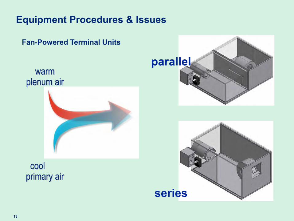
13
cool primary air
warm plenum air
Fan-Powered Terminal Units
series
parallel
Equipment Procedures & Issues

14
100%
0%
primary air
plenum air
space load design
cooling load design
heating load
% a
irflo
w to
spa
ce
minimum primary airflow
maximum primary airflow
heating tempering
Parallel, Fan-Powered
Equipment Procedures & Issues
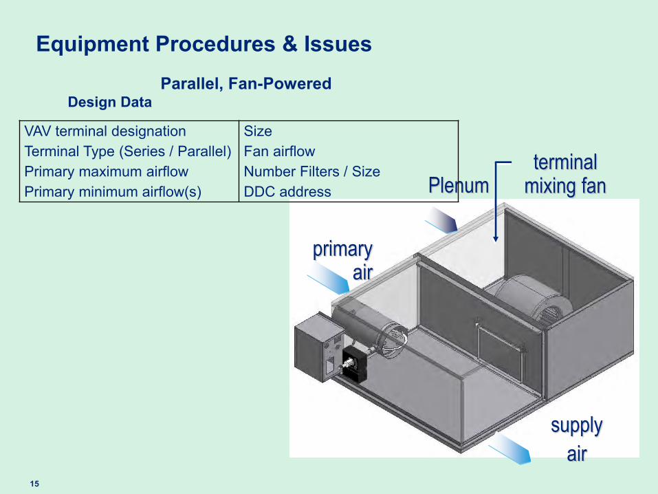
15
Parallel, Fan-Powered
primary air
supply
air
terminal mixing fan Plenum
Equipment Procedures & Issues
VAV terminal designation
Terminal Type (Series / Parallel) Primary maximum airflow Primary minimum airflow(s)
Size
Fan airflow
Number Filters / Size
DDC address
Design Data
16
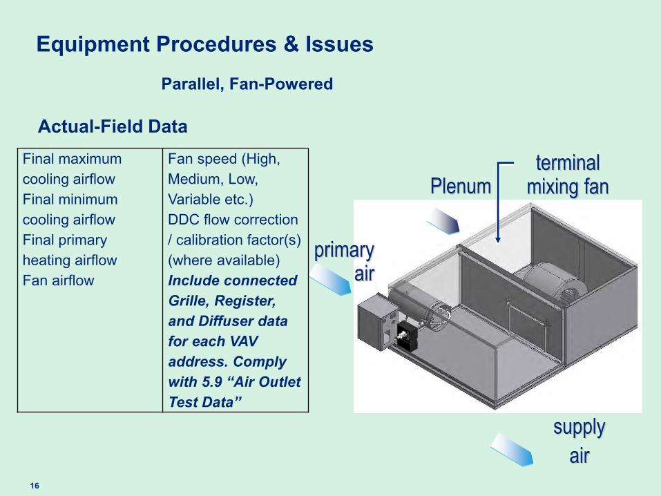
Parallel, Fan-Powered
primary air
supply
air
terminal mixing fan Plenum
Equipment Procedures & Issues
Final maximum cooling airflow Final minimum cooling airflow
Final primary heating airflow
Fan airflow
Fan speed (High, Medium, Low, Variable etc.) DDC flow correction / calibration factor(s) (where available) Include connected Grille, Register, and Diffuser data for each VAV address. Comply with 5.9 “Air Outlet Test Data”
Actual-Field Data
17
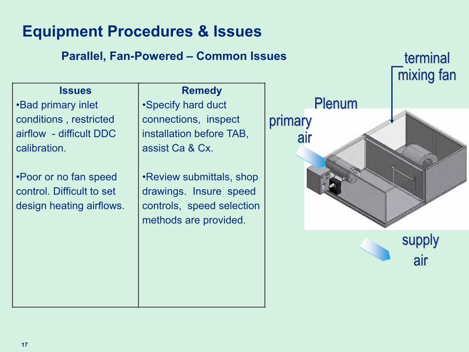
Parallel, Fan-Powered – Common Issues
primary air
supply
air
terminal mixing fan
Plenum
Equipment Procedures & Issues
Issues •Bad primary inlet conditions , restricted airflow - difficult DDC calibration. •Poor or no fan speed control. Difficult to set design heating airflows.
Remedy •Specify hard duct connections, inspect installation before TAB, assist Ca & Cx. •Review submittals, shop drawings. Insure speed controls, speed selection methods are provided.

18
Parallel, Fan-Powered – Common Issues (continued)
primary air
supply
air
terminal mixing fan
Plenum
Equipment Procedures & Issues
Issues •Bad primary inlet conditions , restricted airflow - difficult DDC calibration. •Poor or no fan speed control. Difficult to set design heating airflows. .
Remedy •Location….Location…Location. Review drawings, suggest terminals located in hallways, common areas. •Suggest ECM motors. Quiet operation, slow “ramp-up” no contactor noise. Infinite adjustment. •Definitive reporting. Indicate “fan airflow” versus DDC air flow.
19
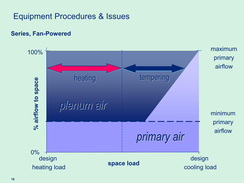
Series, Fan-Powered
100%
0%
primary air
plenum air
space load design
cooling load design
heating load
% a
irflo
w to
spa
ce
minimum primary airflow
maximum primary airflow
heating tempering
Equipment Procedures & Issues
20
supply
air
terminal mixing fan
plenum
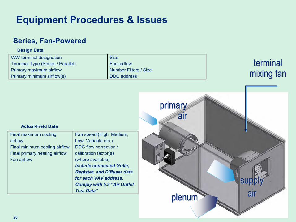
Series, Fan-Powered
primary air
Equipment Procedures & Issues
VAV terminal designation
Terminal Type (Series / Parallel) Primary maximum airflow Primary minimum airflow(s)
Size
Fan airflow
Number Filters / Size
DDC address
Final maximum cooling airflow Final minimum cooling airflow
Final primary heating airflow
Fan airflow
Fan speed (High, Medium, Low, Variable etc.) DDC flow correction / calibration factor(s) (where available) Include connected Grille, Register, and Diffuser data for each VAV address. Comply with 5.9 “Air Outlet Test Data”
Design Data
Actual-Field Data

21
supply
air
terminal mixing fan
plenum
Series, Fan-Powered
primary air
Equipment Procedures & Issues
VAV terminal designation
Terminal Type (Series / Parallel) Primary maximum airflow Primary minimum airflow(s)
Size
Fan airflow
Number Filters / Size
DDC address
Final maximum cooling airflow Final minimum cooling airflow
Final primary heating airflow
Fan airflow
Fan speed (High, Medium, Low, Variable etc.) DDC flow correction / calibration factor(s) (where available) Include connected Grille, Register, and Diffuser data for each VAV address. Comply with 5.9 “Air Outlet Test Data”
Design Data
Actual-Field Data
22
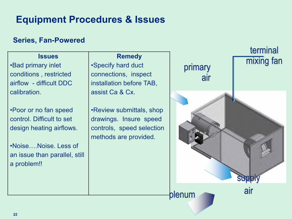
supply
air
terminal mixing fan
plenum
Series, Fan-Powered
primary air
Equipment Procedures & Issues
Issues •Bad primary inlet conditions , restricted airflow - difficult DDC calibration. •Poor or no fan speed control. Difficult to set design heating airflows. •Noise….Noise. Less of an issue than parallel, still a problem!!
Remedy •Specify hard duct connections, inspect installation before TAB, assist Ca & Cx.
•Review submittals, shop drawings. Insure speed controls, speed selection methods are provided.

23
supply
air
terminal mixing fan
plenum
Series, Fan-Powered
primary air
Equipment Procedures & Issues
Issues •Less common, requires more definitive balancing.
•DDC control system only reports primary air.
Remedy •Location….Location… Location. Review drawings, suggest terminals located in hallways, common areas •Suggest ECM motors. Quiet operation, slow “ramp-up” no contactor noise. Infinite adjustment. •Fine balance required at “plenum” entrance to terminal. •Definitive reporting. Indicate “fan airflow” versus DDC air flow.
24
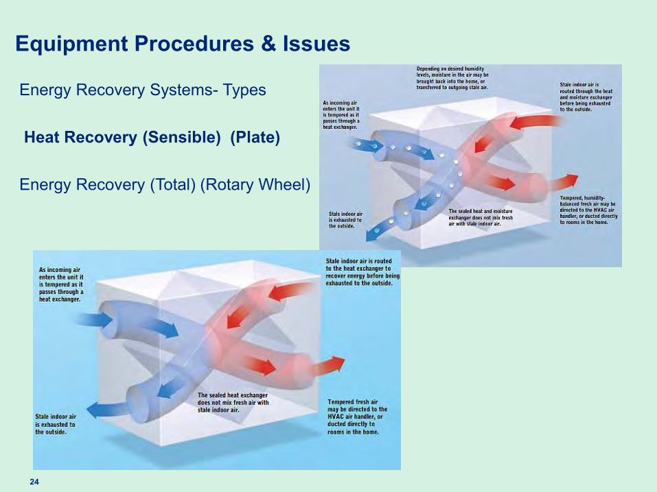
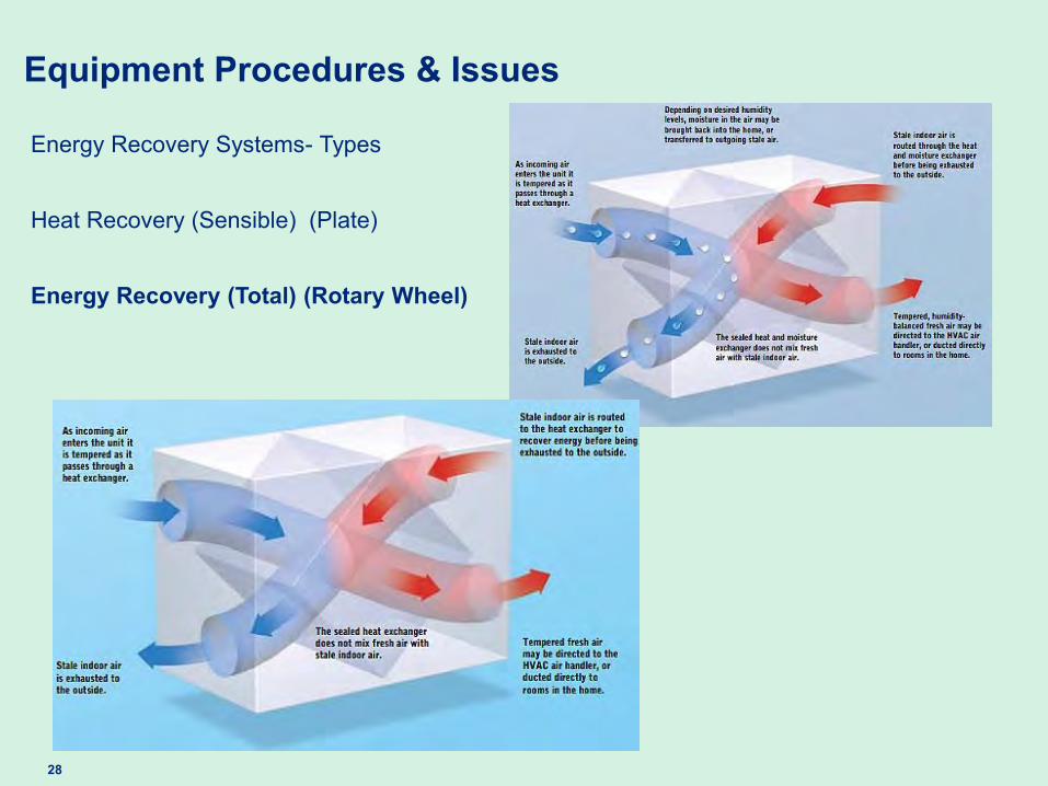
Energy Recovery Systems- Types Heat Recovery (Sensible) (Plate) Energy Recovery (Total) (Rotary Wheel)
Equipment Procedures & Issues
25
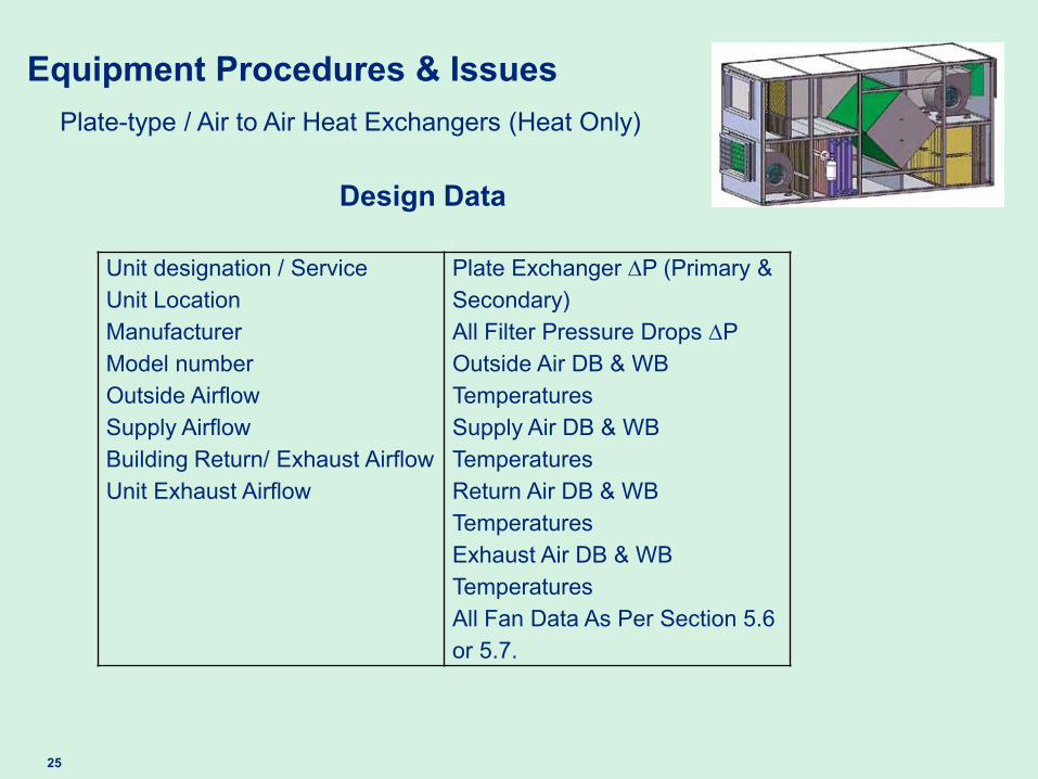
Equipment Procedures & Issues Plate-type / Air to Air Heat Exchangers (Heat Only)
Unit designation / Service
Unit Location
Manufacturer Model number Outside Airflow
Supply Airflow
Building Return/ Exhaust Airflow
Unit Exhaust Airflow
Plate Exchanger P (Primary & Secondary) All Filter Pressure Drops P
Outside Air DB & WB Temperatures
Supply Air DB & WB Temperatures
Return Air DB & WB Temperatures
Exhaust Air DB & WB Temperatures
All Fan Data As Per Section 5.6 or 5.7.
Design Data
26
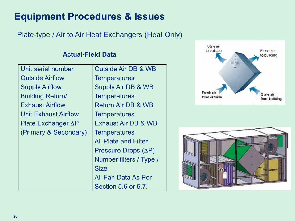
Plate-type / Air to Air Heat Exchangers (Heat Only)
Actual-Field Data
Unit serial number Outside Airflow
Supply Airflow
Building Return/ Exhaust Airflow
Unit Exhaust Airflow
Plate Exchanger P (Primary & Secondary)
Outside Air DB & WB Temperatures
Supply Air DB & WB Temperatures
Return Air DB & WB Temperatures
Exhaust Air DB & WB Temperatures
All Plate and Filter Pressure Drops (P) Number filters / Type / Size
All Fan Data As Per Section 5.6 or 5.7.

27
Equipment Procedures & Issues Plate-type / Air to Air Heat Exchangers
Issues • Limited or no access to unit for evaluation. •Plugged heat exchanger passages. •Burst (or breached) plate frame passages. •Systems are commonly used in lab or dirty environments.
•Freeze-ups in the air passages…!!! By-pass dampers??
Remedy •Insure during pre-balance inspections / site visits confirm that all testing requirements can be accomplished. •Caution installing contractor to develop and maintain an aggressive filter verification program during start-up and construction phase operation.
Remedy •Insure caution is used during early use of units. Large differential pressures at the plates can cause rupture between airstreams..!!!! •Insure that all exhaust ducts are properly sealed, properly routed and room or space relationships are as per spec.
28
Energy Recovery Systems- Types Heat Recovery (Sensible) (Plate) Energy Recovery (Total) (Rotary Wheel)
Equipment Procedures & Issues

29
Equipment Procedures & Issues
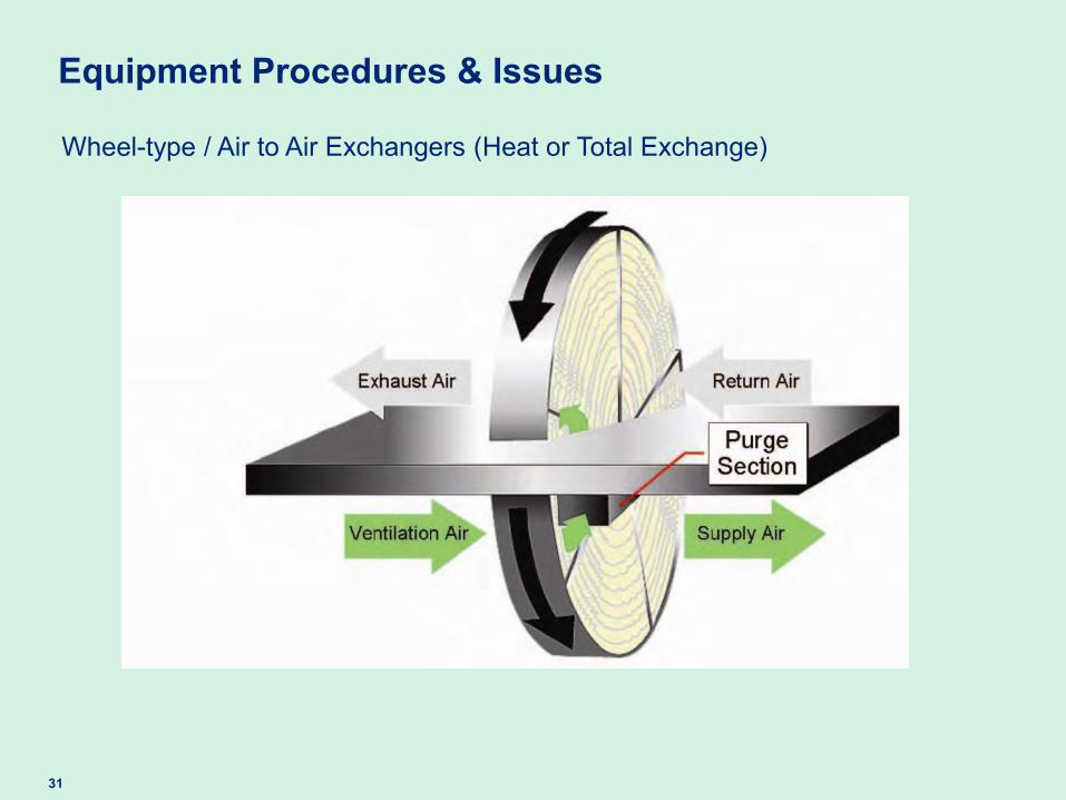
Wheel-type / Air to Air Exchangers (Heat or Total Exchange)
Design Data
Unit designation / Service Unit Location Manufacturer Model number Outside Airflow Supply Airflow Building Return/ Exhaust Airflow Unit Exhaust Airflow Transfer Wheel “Purge Airflow”
Transfer Wheel P (Both Air Paths) All Filter Pressure Drops P Outside Air DB & WB Temperatures Supply Air DB & WB Temperatures Return Air DB & WB Temperatures Exhaust Air DB & WB Temperatures All Fan Data As Per Section 5.6 or 5.7.

30
Equipment Procedures & Issues Wheel-type / Air to Air Exchangers (Heat or Total Exchange)
Actual-Field Data
Unit designation / Service Unit Location Manufacturer Model number Outside Airflow Supply Airflow Building Return/ Exhaust Airflow Unit Exhaust Airflow Transfer Wheel “Purge Airflow”
Transfer Wheel P (Both Air Paths) All Filter Pressure Drops P Outside Air DB & WB Temperatures Supply Air DB & WB Temperatures Return Air DB & WB Temperatures Exhaust Air DB & WB Temperatures All Fan Data As Per Section 5.6 or 5.7.
31
Equipment Procedures & Issues
Wheel-type / Air to Air Exchangers (Heat or Total Exchange)

32
Equipment Procedures & Issues
Wheel-type / Air to Air Exchangers (Heat or Total Exchange)
Issues • Limited or no access to unit for evaluation. •Plugged and contaminated wheel surfaces. •Exchange wheel deflection.
•Frost control @ wheel. Bypass dampers…??
Remedy •Insure during pre-balance inspections / site visits confirm that all testing requirements can be accomplished. •Caution installing contractor to develop and maintain an aggressive filter verification program during start-up and construction phase operation.
Remedy Insure caution is used during early use of units. Large differential pressures at the wheel or using just the supply or exhaust track can cause damaging deflection @ the wheel cassett..!!!!
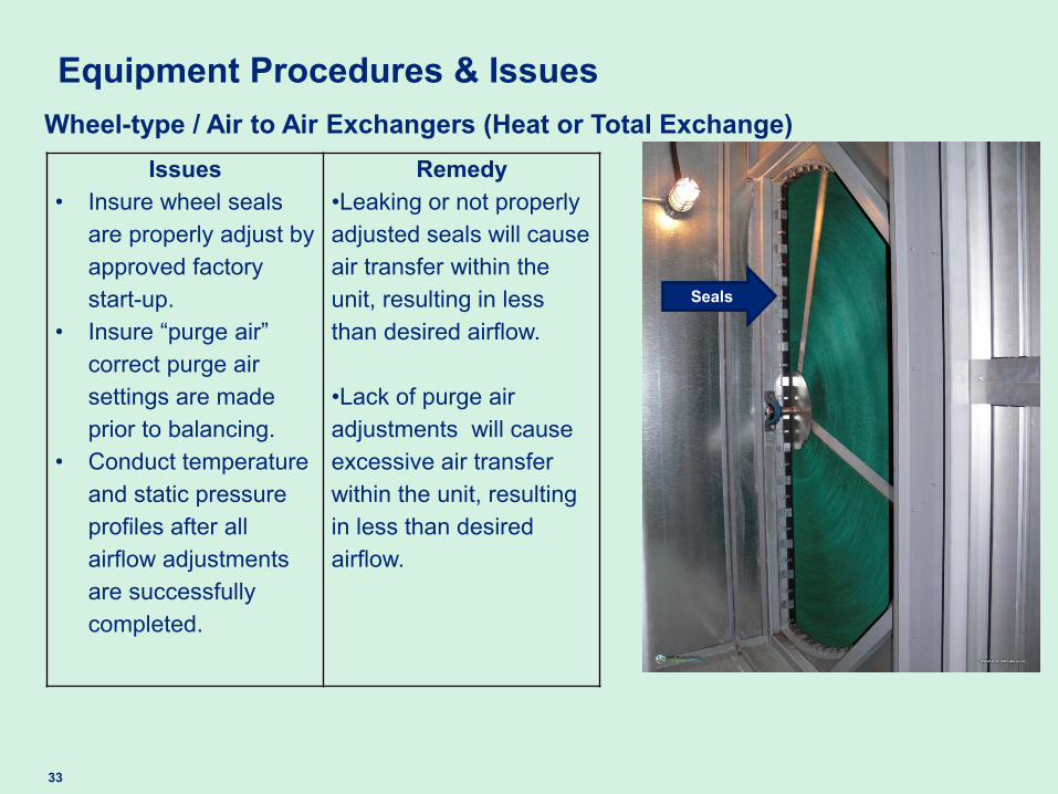
33
Equipment Procedures & Issues Wheel-type / Air to Air Exchangers (Heat or Total Exchange)
Issues • Insure wheel seals
are properly adjust by approved factory start-up.
• Insure “purge air” correct purge air settings are made prior to balancing.
• Conduct temperature and static pressure profiles after all airflow adjustments are successfully completed.
Remedy •Leaking or not properly adjusted seals will cause air transfer within the unit, resulting in less than desired airflow.
•Lack of purge air adjustments will cause excessive air transfer within the unit, resulting in less than desired airflow.
Seals

34
Summary: State of Our Industry
• NEBB’s updated Procedural Standards are a reflection of the more complex and demanding HVAC systems.
• Training and testing of our TAB Professionals and Technicians is increasing in intensity, frequency and rigor.
• NEBB is working tirelessly in our expanding sustainable environments to insure energy conservation and healthy indoor environments.
• Future topics…..Hydronic Systems
35
Contact Information
Tom Hanlon, NEBB’s TAB Committee Telephone: +1.501.749.2122 Email: [email protected] Rodney Hinton, NEBB’s TAB Committee Telephone: +1.704.587.7073 Email: [email protected] Leonard Maiani, NEBB’s Technical Director Telephone: +1.208.449.6145 Email: [email protected].
36
Thank you for joining the webcast.
To improve future NEBBinars, please take a minute to answer a brief survey that will be sent to you.

37 2014 NEBB. All rights reserved.