near-field characterization of propagating optical...
TRANSCRIPT

Near-field characterization of propagating optical modes in photonic crystal waveguides
Maxim Abashin Department of Electrical and Computer Engineering, University of California, San Diego, 9500 Gilman Drive, La
Jolla, CA 92093-0407 [email protected]
Pierpasquale Tortora and Iwan Märki Institute of Microtechnology, University of Neuchâtel, Rue A.-L. Breguet 2, 2000 Neuchâtel, Switzerland
Uriel Levy Department of Electrical and Computer Engineering, University of California, San Diego, 9500 Gilman Drive, La
Jolla, CA 92093-0407
Wataru Nakagawa, Luciana Vaccaro and Hans Peter Herzig Institute of Microtechnology, University of Neuchâtel, Rue A.-L. Breguet 2, 2000 Neuchâtel, Switzerland
Yeshaiahu Fainman Department of Electrical and Computer Engineering, University of California, San Diego, 9500 Gilman Drive, La
Jolla, CA 92093-0407 [email protected]
Abstract: We analyze the propagating optical modes in a Silicon membrane photonic crystal waveguide, based on subwavelength-resolution amplitude and phase measurements of the optical fields using a heterodyne near-field scanning optical microscope (H-NSOM). Fourier analysis of the experimentally obtained optical amplitude and phase data permits identification of the propagating waveguide modes, including the direction of propagation (in contrast to intensity-only measurement techniques). This analysis reveals the presence of two superposed propagating modes in the waveguide. The characteristics of each mode are determined and found to be consistent with theoretical predictions within the limits of fabrication tolerances. An analysis of the relative amplitudes of these two modes as a function of wavelength show periodic oscillation with a period of approximately 3.3 nm. The coupling efficiency between the ridge waveguide and the photonic crystal waveguide is also estimated and found to be consistent with the internal propagating mode characteristics. The combination of high-sensitivity amplitude and phase measurements, subwavelength spatial resolution, and appropriate interpretive techniques permits the in-situ observation of the optical properties of the device with an unprecedented level of detail, and facilitates the characterization and optimization of nanostructure-based photonic devices and systems.
©2006 Optical Society of America
OCIS codes: (230.7370) Waveguides; (180.5810) Scanning microscopy.
References and links
1. A. Lewis, M. Isaacson, A. Harootunian and A. Murray, “Development of a 500 Å spatial resolution light microscope : I. light is efficiently transmitted through λ/16 diameter apertures,” Ultramicroscopy 13, 227-231 (1984).
(C) 2006 OSA 20 February 2006 / Vol. 14, No. 4 / OPTICS EXPRESS 1643#10231 - $15.00 USD Received 9 January 2006; revised 3 February 2005; accepted 3 February 2006

2. D.W. Pohl, W. Denk and M. Lanz, “Optical stethoscopy: Image recording with resolution λ/20,”Appl. Phys. Lett., 44, 651-653 (1984).
3. M. L. M. Balistreri H. Gersen, J. P. Korterik, L. Kuipers, N. F. van Hulst, “Tracking femtosecond laser pulses in space and time,” Science 294, 1080–1082 (2001).
4. K. Okamoto, M. Loncar, T. Yoshie, A. Scherer, Y. Qiu, and P. Gogna, “Near-field scanning optical microscopy of photonic crystal nanocavities,” Appl. Phys. Lett. 82, 1676–1678 (2003).
5. P. Kramper, M. Kafesaki, C. M. Soukoulis, A. Birner, F. Muller, U. Gosele, R. B. Wehrspohn, J. Mlynek, and V. Sandoghdar, “Near-field visualization of light confinement in a photonic crystal microresonator,” Opt. Lett. 29, 174–176 (2004).
6. A. Bouhelier, M. R. Beversluis, and L. Novotny, “Near-field scattering of longitudinal fields,” Appl. Phys. Lett. 82, 4596–4598 (2003).
7. A. Bouhelier, M. R. Beversluis, and L. Novotny, “Characterization of nanoplasmonic structures by locally excited photoluminescence,” Appl. Phys. Lett. 83, 5041–5043 (2003).
8. S. Gotzinger, S. Demmerer, O. Benson, and V. Sandoghdar, “Mapping and manipulating whispering gallery modes of a microsphere resonator with a near-field probe,” J. Microscopy 202, 117–121 (2000).
9. I. Bozhevolnyi, V.S. Volkov, T. Søndergaard, A. Boltasseva, P.I. Borel and M. Kristensen, “Near-field imaging of light propagation in photonic crystal waveguides: Explicit role of Bloch harmonics,” Phys. Rev. B, 66, 235204 1-9 (2002).
10. V.S. Volkov, I. Bozhevolnyi, P.I. Borel, L. H. Frandsen, and M. Kristensen, “Near-field characterization of low-loss photonic crystal waveguides,” Phys. Rev. B, 72, 035118 1-7 (2005).
11. M. L. M. Balistreri, J. P. Korterik, L. Kuipers, and N. F. van Hulst, “Local observations of phase singularities in optical fields in waveguide structures,” Phys. Rev. Lett. 85, 294–297 (2000).
12. A. Nesci, R. Dändliker, and H. P. Herzig, “Quantitative amplitude and phase measurement by use of a heterodyne scanning near-field optical microscope,” Opt. Lett. 26, 208–210 (2001).
13. S. I. Bozhevolnyi, and B. Vohnsen, “Near-field imaging of optical phase and its singularities,” Opt. Comm. 212, 217–223 (2002).
14. R. Engelen, Tim Karle, Henkjan Gersen, Jeroen Korterik, Thomas Krauss, Laurens Kuipers, Niek van Hulst, “Local probing of Bloch mode dispersion in a photonic crystal waveguide,” Optics Express, 13, 4457-4464 (2005).
15. E. Flück, M. Hammer, A.M. Otter, J. P. Korterik, L. Kuipers, and N. F. van Hulst, “Amplitude and phase evolution of optical fields inside periodic photonic structures,” J. Lightwave Technol. 21, 1384–1393 (2003).
16. A. Nesci, and Y. Fainman, “Complex amplitude of an ultrashort pulse with femtosecond resolution in a waveguide using a coherent NSOM at 1550 nm,” in Wave Optics and Photonic Devices for Optical Information Processing II, P. Ambs and F. R. Beyette, Jr., eds., Proc. SPIE 5181, 62–69 (2003).
17. J. C. Gates, C. W. J. Hillman, J. C. Baggett, K. Furusawa, T. M. Monro, and W. S. Brocklesby, “Structure and propagation of modes of large mode area holey fibers,” Opt. Express 12, 847–852 (2004).
18. H. Gersen, T. J. Karle, R. J. P. Engelen, W. Bogaerts, J. P. Korterik, N. F. van Hulst, T. F. Krauss, and L. Kuipers, “Real-Space Observation of Ultraslow Light in Photonic Crystal Waveguides,” Phys. Rev. Lett. 94, 073903 1–4 (2005).
19. H. Gersen, T. J. Karle, R. J. P. Engelen, W. Bogaerts, J. P. Korterik, N. F. van Hulst, T. F. Krauss, and L. Kuipers, “Direct Observation of Bloch Harmonics and Negative Phase Velocity in Photonic Crystal Waveguides,” Phys. Rev. Lett. 94, 123901 1–4 (2005).
20. P. Tortora, M. Abashin, I. Märki, W. Nakagawa, L. Vaccaro, U. Levy, M. Salt, H. P. Herzig and Y. Fainman, “Observation of amplitude and phase in ridge and photonic crystal waveguides operating at 1.55 µm using heterodyne scanning near-field optical microscopy,” Opt. Lett. 30, 2885–2887 (2005).
21. S. G. Johnson and J. D. Joannopoulos, “Block-iterative frequency-domain methods for Maxwell's equations in a planewave basis,” Optics Express 8, 173–190 (2001).
22. I. Märki, M. Salt, R. Stanley, U. Staufer, and H. P. Herzig, “Characterization of photonic crystal waveguides based on Fabry-Pérot interference,” J. Appl. Phys. 96, 6966–6969 (2004).
1. Introduction
Since the first demonstrations of the near-field scanning optical microscope (NSOM) in 1984 [1,2], the technique has proven to be an important tool for subwavelength resolution observation of various optical field configurations [3-5], including evanescent and other non-propagating fields [6-10]. A more recent innovation, the heterodyne NSOM (H-NSOM) [11], permits the near-field measurement of both amplitude and phase, providing previously inaccessible information about the optical fields under investigation. This technique has been applied to a large number of studies, in particular involving subwavelength-scale structures, localized optical field phenomena, and photonic crystals (PhCs) in the visible range [12-14].
(C) 2006 OSA 20 February 2006 / Vol. 14, No. 4 / OPTICS EXPRESS 1644#10231 - $15.00 USD Received 9 January 2006; revised 3 February 2005; accepted 3 February 2006

With the recent rapid developments in optical fiber communications and semiconductor-based photonic devices and systems, there is a clear need for H-NSOM tools operating in the near infrared wavelength range. Although H-NSOM has only recently been adapted to this wavelength band, several interesting applications and results have already been reported [15-19]. In particular, for photonic devices based on subwavelength-scale features, such as photonic crystal structures, this technique is an indispensable diagnostic tool. Typically, characterization of such devices is carried out in the far field, by measuring the spectral response of the light that emerges from the structure. Instead, by measuring the optical fields as they propagate inside the device—with subwavelength resolution and with amplitude and phase information—H-NSOM provides significant additional information about the optical properties of the device [18,19], and greatly facilitates both understanding the operation of the device and improving its performance. Furthermore, as manufacturing technology advances and photonic systems achieve higher degrees of complexity and integration, localized in-situ characterization of optical fields will become increasingly useful and necessary.
In a previous letter [20], we demonstrated the feasibility of measuring the amplitude and the phase of the propagating optical field in ridge and Silicon membrane PhC waveguides operating around 1550 nm wavelength using the H-NSOM technique. In this paper, we focus on a single example—a straight square-lattice Silicon membrane PhC waveguide—and perform a significantly more detailed analysis of the optical propagation characteristics of the device based on H-NSOM measurements. A detailed description of the H-NSOM tool (based on Nanonics MultiView 2000™ System) that was used for these measurements is given in [16]. By comparing measurement results obtained for a range of optical wavelengths around 1550 nm, we determine a number of important characteristics concerning the propagating modes in the waveguide, including the number of propagating modes, their effective wavelength, their relative amplitudes, the position of the band edge, and the approximate input coupling efficiency as a function of wavelength. This information supports a much better understanding of the propagation of light within such a structure, enabling a detailed comparison of the experimental results with theoretical predictions. Overall, this investigation demonstrates the range of information provided by high-quality H-NSOM measurements, in many cases yielding insight that is unattainable using far-field optical characterization techniques.
In the next section we provide a brief description of the fabricated PhC waveguide sample and describe its expected properties from the calculated dispersion diagram. In Section 3 we present experimentally obtained results validating the existence and the position of the PhC band edge. Section 4 presents measurements of the complex amplitude for the propagating modes in the PhC waveguide, and the subsequent spectral analysis to determine the mode propagation properties. Section 5 is devoted to the measurement of input coupling loss at the interface of a single mode ridge waveguide and the PhC waveguide. Section 6 concludes the manuscript.
2. Description of the PhC waveguide
The optical micrograph in Fig. 1(a) shows the layout of the fabricated device, consisting of a pair of ridge waveguides coupled to the edges of a PhC waveguide. A square mesh PhC lattice with a period of 496 nm, air holes of radius 190 nm, and a membrane thickness of 290 nm (see Fig. 1(b)) is used to create a W1 PhC waveguide by removing a single row of air holes (here W1 stands for PhC waveguide with one missing row of holes). The total length of the W1 PhC waveguide is about 25 microns. The device is fabricated in a silicon on insulator (SOI) wafer using electron beam lithography of PMMA resist for patterning, followed by reactive ion etching to transfer the pattern into the SOI substrate. The oxide layer below the PhC structure was removed using a buffered hydrofluoric acid vapor etch, thereby creating a PhC membrane. With this configuration a symmetric mode in the vertical direction can be obtained, and the radiation loss is reduced significantly.
(C) 2006 OSA 20 February 2006 / Vol. 14, No. 4 / OPTICS EXPRESS 1645#10231 - $15.00 USD Received 9 January 2006; revised 3 February 2005; accepted 3 February 2006
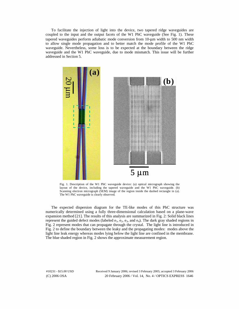
To facilitate the injection of light into the device, two tapered ridge waveguides are coupled to the input and the output facets of the W1 PhC waveguide (See Fig. 1). These tapered waveguides perform adiabatic mode conversion from 10-μm width to 500 nm width to allow single mode propagation and to better match the mode profile of the W1 PhC waveguide. Nevertheless, some loss is to be expected at the boundary between the ridge waveguide and the W1 PhC waveguide, due to mode mismatch. This issue will be further addressed in Section 5.
5 μm20 μ
m
(a)(b)
5 μm20 μ
m
(a)(b)
Fig. 1. Description of the W1 PhC waveguide device: (a) optical micrograph showing the layout of the device, including the tapered waveguide and the W1 PhC waveguide. (b) Scanning electron micrograph (SEM) image of the region inside the dashed rectangle in (a). The W1 PhC waveguide is clearly observed.
The expected dispersion diagram for the TE-like modes of this PhC structure was numerically determined using a fully three-dimensional calculation based on a plane-wave expansion method [21]. The results of this analysis are summarized in Fig. 2: Solid black lines represent the guided defect modes (labeled e1, e2, e3, and e4). The dark gray shaded regions in Fig. 2 represent modes that can propagate through the crystal. The light line is introduced in Fig. 2 to define the boundary between the leaky and the propagating modes: modes above the light line leak energy whereas modes lying below the light line are confined in the membrane. The blue shaded region in Fig. 2 shows the approximate measurement region.
(C) 2006 OSA 20 February 2006 / Vol. 14, No. 4 / OPTICS EXPRESS 1646#10231 - $15.00 USD Received 9 January 2006; revised 3 February 2005; accepted 3 February 2006

0.5
00.1 0.2 0.3 0.4 0.5
0.05
0.3
0.35
0.4
0.45
0
wavevector [2ð/a]
freq
uen
cy[c
/a]
measurement range
0.25
0.1
0.15
0.2
0.99
9.94
1.66
1.42
1.24
1.10
1.99
4.97
3.31
2.49
wav
elength
[µm
]
Fig. 2. Calculated dispersion diagram for TE-like guided modes in the photonic crystal waveguide. Solid black lines represent the guided defect modes: e1, e2, e3, and e4. The dark gray shaded regions show modes that can propagate through the crystal. The light line defines the boundary between the leaky and the propagating modes. The blue shaded region shows the approximate measurement region centered at the wavelength of 1.5 μm.
The dispersion diagram of Fig. 2 shows that in the measurement wavelength range we expect to excite two modes, labeled e1 and e2. The cutoff frequency for mode e1 occurs at a normalized frequency of about 0.325, corresponding to a wavelength of about 1525 nm. The mode e2 exists for the entire frequency range under study. However, for wavelengths shorter than about 1525 nm, the e2 mode lies in the dark gray region, where PhC states are allowed, leading to leaking of the light from the waveguide into the PhC structure. In the following section we investigate experimentally these theoretical predictions.
3. Characterization of photonic crystal band edge
We first investigate the guided modes of the W1 PhC waveguide at a wavelength of 1560 nm, where we expect the light to be strongly guided in the waveguide channel. The H-NSOM system is used to measure amplitude and phase images of the W1 PhC waveguide following the procedures described in Ref. [13]: the light from a fiber-coupled tunable laser is split into two arms in a Mach Zehnder interferometric arrangement. One arm has a tapered fiber that is used to couple light into the cleaved edge of the fabricated device. An NSOM tip is introduced into the evanescent field just above the W1 PhC waveguide shown in Fig. 1(b). The optical field coupled into the NSOM tip is mixed with the light in the reference arm of the Mach-Zehnder interferometer and introduced into a photodetector followed by signal processing [13]. The NSOM tip is used to scan an area of 7x7 μm and the detected images are used to reconstruct the time-domain propagation of light, as shown in Fig. 3. The results of Fig. 3 show that the propagating light is well confined to the waveguide channel and has a
(C) 2006 OSA 20 February 2006 / Vol. 14, No. 4 / OPTICS EXPRESS 1647#10231 - $15.00 USD Received 9 January 2006; revised 3 February 2005; accepted 3 February 2006

predominantly stationary mode configuration. The movie was generated by adding for each frame a time-dependent phase to the measured phase, and taking the real part of the resulting complex amplitude. Such time-domain reconstruction of the optical field is only possible if amplitude and phase data are available.
Fig. 3. (465 KB) Movie showing instantaneous optical field at wavelength of 1560 nm propagating in the W1 PhC waveguide as calculated from the measured complex amplitude. Scanning range is 7 by 7 microns.
We also investigate the excitation of modes well within the PBG and close to the edge of the PBG. As expected, at an optical frequency close to the edge of the PBG (corresponding to a wavelength of 1520.0 nm) the optical field is not strongly guided, as is clearly seen from the detected amplitude and phase images shown in Figs. 4(a) and 4(b), respectively. In contrast, for a wavelength of 1560.0 nm (well within the PBG), the amplitude and phase images of Figs. 4(c) and 4(d), respectively, reveal well-guided optical propagation. The amplitude image (Fig. 4(c)) shows that the light is localized to the waveguide channel, and the phase image (Fig. 4(d)) shows planar phase fronts.
(C) 2006 OSA 20 February 2006 / Vol. 14, No. 4 / OPTICS EXPRESS 1648#10231 - $15.00 USD Received 9 January 2006; revised 3 February 2005; accepted 3 February 2006

(a) (b)
(c) (d)
Fig. 4. Images of measured amplitude and phase of the optical fields propagating in the W1 PhC waveguide at wavelengths of 1520 nm (a, b, respectively) and 1560 nm (c, d, respecitvely). Below the band edge (1520 nm) the propagating modes are not strongly confined to the waveguide channel, whereas modes within the bandgap of the PhC (1560 nm) demonstrate strong confinement of light in the waveguide channel (c) and planar phase fronts (d) in the waveguide region.
4. Photonic crystal waveguide modes
Next we perform detailed experimental measurements and analysis of the spectral modes propagating in W1 PhC waveguide, and compare these results with theoretical predictions.
4.1. NSOM measurement of waveguide spectral characteristics
The spectral measurement of the optical fields propagating in the W1 PhC waveguide is performed over optical frequencies within the bandgap, corresponding to a wavelength range of 1556.6 nm–1559.8 nm. Fig. 5 shows nine representative images of the amplitude and phase data obtained using the H-NSOM at different wavelengths in this range (note that the amplitude and phase color keys are similar to those of Fig. 4). It is evident from the results shown in Fig. 5 that the propagating mode characteristics depend strongly on the wavelength. For example, at wavelength 1556.6 nm, the transverse profile of the propagating mode
(C) 2006 OSA 20 February 2006 / Vol. 14, No. 4 / OPTICS EXPRESS 1649#10231 - $15.00 USD Received 9 January 2006; revised 3 February 2005; accepted 3 February 2006

appears to be that of the fundamental mode—the amplitude has a single lobe with even transverse symmetry, and the phase fronts within the waveguide channel are flat along the transverse direction and uniformly spaced. Similar characteristics are observed again at wavelength 1559.8 nm. However, at a wavelength of 1558.2 nm (i.e., halfway between these two values), a very different profile with odd transverse symmetry is observed. Moreover, at intervening wavelengths (e.g. wavelengths between 1558.2 nm and 1559.8 nm) we see a gradual transition between the dominant even and odd mode structures. These results reveal a periodic variation of the propagating mode characteristics with respect to the optical frequency.
Next we exploit the unique advantage of the H-NSOM technique that provides the 2-D complex amplitude information of the optical field for an operating device. Specifically, we perform a spectral analysis of the propagating modes at each excitation wavelength, thereby quantifying the modal power spectral density.
Fig. 5. A sequence of amplitude and phase images of the guided modes in a W1 PhC waveguide measured for a sequence of wavelengths from 1556.6 nm to 1559.8 nm in increments of 0.4 nm. The images are obtained by scanning the H-NSOM tip over an area of 7x7 micrometers above the W1 PhC waveguide.
4.2. Complex-amplitude Fourier analysis
Detailed mode characteristics can be discerned by performing a Fourier analysis of the detected H-NSOM complex amplitude measurements. The ability to perform a Fourier transform operation on the measured near field complex amplitude data is clearly a significant advantage unique to the H-NSOM method in comparison to other existing techniques. For example, the available phase information allows us to calculate the propagation constant for each mode and to distinguish between forward and backward propagating fields. Since the light in the W1 PhC waveguide propagates along a specific direction, we can perform a one-dimensional Fourier transform along the propagation direction (i.e., the z-axis) to reveal the spatial frequency content of the complex amplitude. Figure 6 shows images of the resulting magnitude of the 1-D Fourier transform applied to the complex amplitude of the optical field determined from the NSOM data, with the x-axis remaining in the spatial domain, and the z-axis replaced by the corresponding spatial frequency in the z-direction. The spectral images for wavelengths 1556.6 nm and 1558.2 are shown in Figs. 6(a) and 6(b), respectively. The
(C) 2006 OSA 20 February 2006 / Vol. 14, No. 4 / OPTICS EXPRESS 1650#10231 - $15.00 USD Received 9 January 2006; revised 3 February 2005; accepted 3 February 2006

peaks observed in these images are associated with the various modes propagating along the z-axis.
Fig. 6. Spectral content of the optical field propagating in the z-direction when the guided optical field is excited in the W1 PhC waveguide at optical frequencies corresponding to (a) the dominant even mode at a wavelength of 1556.6 nm, and (b) superposition of even and odd modes at a wavelength of 1558.2 nm.
Figure 6(a) shows that for excitation of the guided mode at a wavelength of 1556.6 nm there is one dominant peak located in the center of the waveguide along the x-axis. For the longer wavelength of 1558.2 nm (Fig. 6(b)), we still observe this peak, but also two additional peaks (centered at positive and negative x-coordinates) appear at a slightly lower spatial frequency. This result implies the propagation of two modes. By observing Fig. 2, it is reasonable to believe that these two modes are e1 and e2. Indeed, this expectation is confirmed in Section 4.3. Moreover, by integrating these 1D Fourier transform results along the transverse direction (i.e., along the x-axis) we obtain the average modal power content of the guided optical fields, shown in Fig. 7. For wavelength 1556.6 nm, Fig. 7(a) shows a single dominant peak indicating predominantly single-mode propagation in the W1 PhC waveguide. This peak
corresponds to an effective wavelength of (1) 0.67effλ ≈ with a corresponding effective
refractive index of (1) 2.34effn ≈ . Note also that there is a smaller peak at the symmetric
position on the negative side of the spectrum, which corresponds to the equivalent counter-propagating (i.e., reflected) mode. In contrast to commonly used NSOM intensity measurements, where forward propagating and backward propagating modes cannot be distinguished, the complex amplitude measurements permit the determination of not only the spatial frequency of the modes, but also their direction of propagation.
For wavelength 1558.2 nm, Fig. 7(b) shows two dominant peaks on the positive side of the spectrum indicating the existence of two forward propagating modes in the W1 PhC
waveguide. These peaks correspond to modes with effective wavelengths of (1) 0.67effλ ≈
and (2) 0.93effλ ≈ , having effective refractive indices of (1) 2.34effn ≈ and (2) 1.68effn ≈ ,
respectively. This result also clearly explains that the modal images shown in Fig. 5 for this wavelength result from the superposition of two co-propagating modes with different propagation constants.
(C) 2006 OSA 20 February 2006 / Vol. 14, No. 4 / OPTICS EXPRESS 1651#10231 - $15.00 USD Received 9 January 2006; revised 3 February 2005; accepted 3 February 2006

(a) (b)
Fig. 7. Spatial spectral content of the light propagating in the W1 PhC waveguide observed using H-NSOM: (a) λ=1556.6 nm; (b) λ=1558.2 nm.
Finally, we perform a Fourier analysis for the NSOM measurements spanning the entire wavelength range shown in Fig. 5 in order to obtain the amplitude of each of the above-mentioned modes as a function of wavelength. These results are summarized in Fig. 8 and clearly indicate a gradual transition from single mode propagation towards dual mode propagation, and back to single mode propagation. Evidently, changing the wavelength can enhance or suppress the appearance of the second, anti-symmetric mode in a periodic fashion. Applying a sinusoidal curve fit to the obtained experimental results yields a wavelength offset of 1557.5 nm and a period of 3.3 nm.
Fig. 8: Fourier spectrum amplitudes vs. excitation wavelength for the two forward-propagating modes observed in the W1 PhC waveguide.
A possible explanation for this periodic behavior is Fabry-Perot interference of
propagating and counter-propagating modes. However, the interference period corresponds to
(C) 2006 OSA 20 February 2006 / Vol. 14, No. 4 / OPTICS EXPRESS 1652#10231 - $15.00 USD Received 9 January 2006; revised 3 February 2005; accepted 3 February 2006

a cavity length of about 150 μm and we are unable to identify such a cavity in our device (the end facet of the waveguide is located further away from the PhC sample). Further investigation is required in order to fully understand the source of this periodic characteristic.
4.3 Comparison with theoretical modal analysis
Next we use the slope of the dispersion diagram in Fig. 2 to estimate the theoretically predicted value of the propagation constants for the two expected modes. We find effective wavelength values of λ1 = 0.57 μm and of λ2 = 0.7 μm for the two modes relevant to our study (modes e1 and e2 respectively). The theoretically predicted effective wavelengths for the e1 and e2 modes are 15% and 25% lower than those measured in our experiments. We attribute these differences to fabrication inaccuracies and the dispersive nature of the modes. In particular, mode e2 is highly dispersive (see Fig. 2) and therefore any small variation in the fabrication conditions and/or environmental and material parameters may have a strong effect on the characteristics of this specific mode.
From our plane wave simulation results we learn that the first mode e1 is symmetric (laterally even) and has a wave vector and field distribution not very different from the fundamental mode of a ridge waveguide (Fig. 9(a)). The second mode e2 is an anti-symmetric (laterally odd) mode and has strong dispersion (Fig. 9(b)).
(a) (b)
Fig. 9. Plane wave expansion simulation showing mode patterns within the PhC waveguide. The modes were calculated using an approximate supercell-based model of the ideal structure. The two lowest-order eigenmodes are shown: (a) even mode e1; (b) odd mode e2.
To investigate how these two modes propagate within the PhC we performed a simulation using the finite-integral time domain method (CST Microwave Studio 5). The simulation results are shown in Fig. 10. By controlling the source illumination profile we select the propagating modes within the W1 PhC waveguide. Fig. 10(a) shows the propagation of the even mode, e1. This simulation result is very similar to the experimental measurements results shown in Fig. 5 for wavelengths of 1556.6 nm and 1559.8 nm. Fig 10(b) shows the propagation of the odd mode and Fig. 10(c) shows the superposition of the two modes. The “snake-like” pattern is due to the beating of the two modes having differing propagation constants. Qualitatively, the calculated field distribution is consistent with the measurements shown in Fig. 5 (e.g., at a wavelength of 1559.40 nm).
(a) (b) (c)
Fig. 10. Finite integral time domain simulations showing the propagation of: (a) even mode, (b) odd mode and (c) superposition of the even and the odd mode.
(C) 2006 OSA 20 February 2006 / Vol. 14, No. 4 / OPTICS EXPRESS 1653#10231 - $15.00 USD Received 9 January 2006; revised 3 February 2005; accepted 3 February 2006

5. Estimation of coupling loss
As a final example of the application of H-NSOM to investigate the detailed optical properties of the PhC waveguide, we estimate the input coupling loss of the device. Specifically, we perform a scan over a region that includes the boundary between the input ridge waveguide and the W1 PhC waveguide. Figure 11 shows a typical scan of the measured amplitude profile clearly demonstrating a significant drop in the field amplitude.
Fig. 11. Near-field amplitude measurement in the area of the input coupling interface between the ridge and the W1 PhC waveguides for wavelength 1553.5 nm. The dotted line indicated the interface between the ridge waveguide (below the line) and the photonic crystal waveguide (above the line).
We calculate the coupling loss between the ridge waveguide and the W1 PhC waveguide by integrating the intensity in the transverse direction over the extent of the waveguide. Since the measured amplitude is not constant along the propagation direction, we estimate an average value of integration for each region. Figure 12 shows a typical variation of the intensity of the guided light along the propagation direction z. The two horizontal lines correspond to the averaged values of intensity for each of the two sections: the ridge and the W1 PhC waveguide. Although the reflection from the ridge to PhC waveguide junction has been shown to be small in far-field measurements [22], our Fourier analysis shows that the integrated intensity of the backward-propagating modes in the ridge waveguide is approximately 50-60% that of the forward-propagating modes, corresponding to roughly 2 dB of reflection loss. This result can be attributed to the input coupling method (a tapered fiber as opposed to the microscope objective used in [22]) possibly leading to the launching of higher order modes. The data in Fig. 11 obtained for the wavelength of 1553.5 nm, shows a 7.1 dB drop of the intensity from the ridge to the W1 PhC waveguide. We believe that the additional loss is the result of out-of-plane radiation in the junction.
(C) 2006 OSA 20 February 2006 / Vol. 14, No. 4 / OPTICS EXPRESS 1654#10231 - $15.00 USD Received 9 January 2006; revised 3 February 2005; accepted 3 February 2006
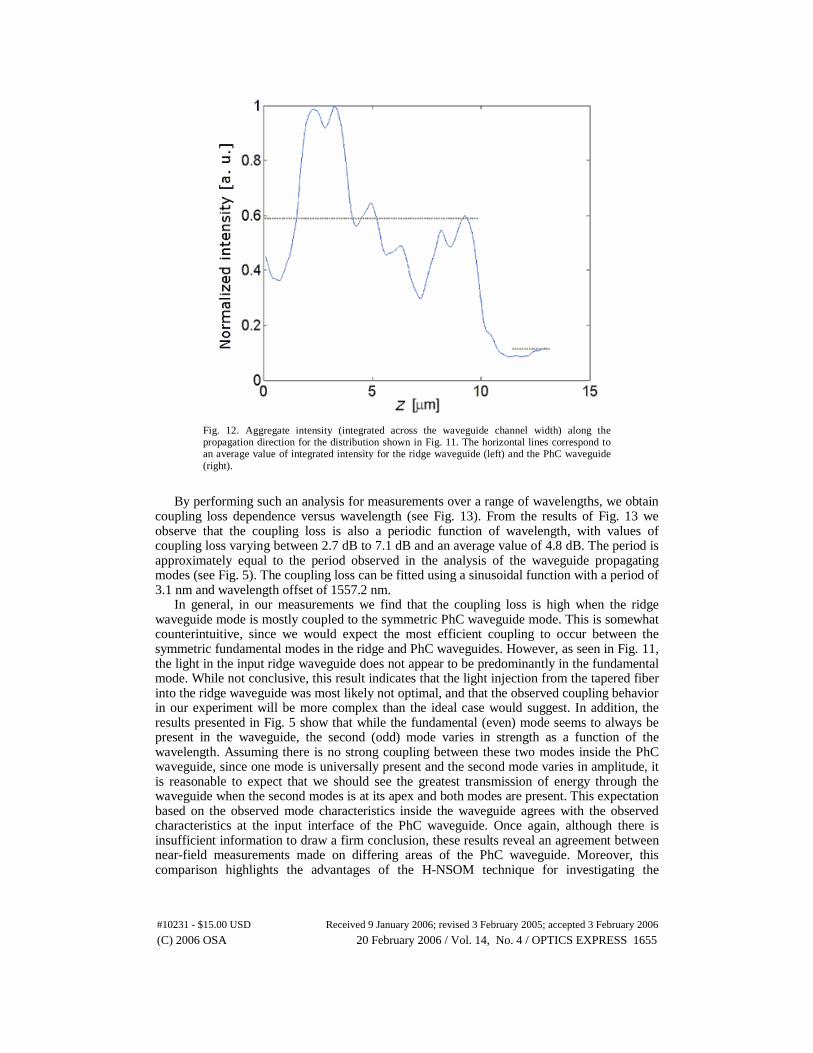
Fig. 12. Aggregate intensity (integrated across the waveguide channel width) along the propagation direction for the distribution shown in Fig. 11. The horizontal lines correspond to an average value of integrated intensity for the ridge waveguide (left) and the PhC waveguide (right).
By performing such an analysis for measurements over a range of wavelengths, we obtain coupling loss dependence versus wavelength (see Fig. 13). From the results of Fig. 13 we observe that the coupling loss is also a periodic function of wavelength, with values of coupling loss varying between 2.7 dB to 7.1 dB and an average value of 4.8 dB. The period is approximately equal to the period observed in the analysis of the waveguide propagating modes (see Fig. 5). The coupling loss can be fitted using a sinusoidal function with a period of 3.1 nm and wavelength offset of 1557.2 nm.
In general, in our measurements we find that the coupling loss is high when the ridge waveguide mode is mostly coupled to the symmetric PhC waveguide mode. This is somewhat counterintuitive, since we would expect the most efficient coupling to occur between the symmetric fundamental modes in the ridge and PhC waveguides. However, as seen in Fig. 11, the light in the input ridge waveguide does not appear to be predominantly in the fundamental mode. While not conclusive, this result indicates that the light injection from the tapered fiber into the ridge waveguide was most likely not optimal, and that the observed coupling behavior in our experiment will be more complex than the ideal case would suggest. In addition, the results presented in Fig. 5 show that while the fundamental (even) mode seems to always be present in the waveguide, the second (odd) mode varies in strength as a function of the wavelength. Assuming there is no strong coupling between these two modes inside the PhC waveguide, since one mode is universally present and the second mode varies in amplitude, it is reasonable to expect that we should see the greatest transmission of energy through the waveguide when the second modes is at its apex and both modes are present. This expectation based on the observed mode characteristics inside the waveguide agrees with the observed characteristics at the input interface of the PhC waveguide. Once again, although there is insufficient information to draw a firm conclusion, these results reveal an agreement between near-field measurements made on differing areas of the PhC waveguide. Moreover, this comparison highlights the advantages of the H-NSOM technique for investigating the
(C) 2006 OSA 20 February 2006 / Vol. 14, No. 4 / OPTICS EXPRESS 1655#10231 - $15.00 USD Received 9 January 2006; revised 3 February 2005; accepted 3 February 2006

properties of nanoscale photonic devices, and demonstrates its potential for providing new and useful insight into these characteristics.
Fig. 13. Experimentally obtained values for coupling loss at the coupling interface between the ridge and the W1 PhC waveguides for different input wavelengths.
6. Conclusions
We have analyzed the optical modes propagating in a Silicon-membrane photonic crystal waveguide, based on subwavelength-resolution amplitude and phase measurements of the optical fields using a heterodyne near-field scanning optical microscope (H-NSOM). Fourier analysis of the experimentally obtained optical amplitude and phase data allowed the identification of the propagating modes of the waveguide, including the direction of propagation (in contrast to intensity-only measurement techniques). This analysis revealed the presence of two superposed propagating modes in the waveguide. The propagation characteristics of these two modes were found to be in reasonable agreement with theoretical predictions within the limits of fabrication tolerances—the strongly dispersive waveguide modes mean that the exact propagation characteristics are extremely sensitive to a variety of parameters, including the material refractive index, membrane thickness, hole diameter and shape, and other fabrication defects. An analysis of the relative amplitudes of these two modes as a function of wavelength shows a periodic variation. Finally, by scanning the input region of the PhC waveguide, an estimation of the coupling efficiency between the ridge waveguide and the photonic crystal waveguide was made. The coupling efficiency was also found to have a periodic nature as a function of wavelength, with a period very close to the period measured for the internal propagating mode characteristics.
These results demonstrate that the characterization technique based on H-NSOM provides a wealth of information concerning the optical fields propagating in the device under study. In
(C) 2006 OSA 20 February 2006 / Vol. 14, No. 4 / OPTICS EXPRESS 1656#10231 - $15.00 USD Received 9 January 2006; revised 3 February 2005; accepted 3 February 2006

particular, the combination of the high-sensitivity amplitude and phase measurements, subwavelength resolution, and appropriate analytical and interpretive techniques permit the in-situ observation of the optical field properties with an unprecedented level of detail. Consequently, as nanostructure-based photonic devices and systems continue to grow in complexity and scale, the H-NSOM technique will likely prove to be an invaluable tool in observing the local optical fields in such devices, understanding the optical interactions between integrated components, and optimizing the performance of photonic systems based on this technology.
Acknowledgments
The authors would like to acknowledge M. Salt for the realization of the photonic crystal waveguide, and F. Schädelin, S. Gautsch, U. Staufer, and N. F. de Rooij (IMT, UniNE) for its fabrication. The authors also thank R. Rokitski and K. Tetz for their assistance in setting up and debugging the H-NSOM system. This research was supported in part by DARPA, National Science Foundation, AFOSR and the Swiss National Science Foundation.
(C) 2006 OSA 20 February 2006 / Vol. 14, No. 4 / OPTICS EXPRESS 1657#10231 - $15.00 USD Received 9 January 2006; revised 3 February 2005; accepted 3 February 2006