near east university faculty of engineeringdocs.neu.edu.tr/library/6343013231.pdf · ·...
TRANSCRIPT

NEAR EAST UNIVERSITY
Faculty of Engineering
Department of Electrical Electronic Engineering
LIGHTING AUTOMATION
Graduation Project
EE-400
Student: Emmanuel Ejike Apeh (20093021)
Supervisor: Assoc. Prof. Dr. Ozgur Ozerdam
Mr. Mohammed Km-ail
Nicosia - 2014

ACKNOWLEDGEMENT
My utmost gratitude to God Almighty for it is by his grace that i was able to fulfill this mission.
My exceeding love and gratitude to my family for their love, prayers and unlimited support. Their encouragement is the cornerstone behind my zeal.
Special gratitude to my course mate Adnan for the efforts he put into this work.
I would also like to thank my supervisor Assoc. Prof. DR Ozgur Ozerdam and Mr. Mohammed KMAIL for their guidelines and assistance during the course of this project.
My sincere appreciation to all my friends who contributed immensely to this project most specially Tobechukwu Ejezie.

ABSTRACT
This project explores the concept of lighting automation and its construction and control mechanisms through the use of a lighting control system.
This project demonstrates a simple home automation system that allows the user to control it from a computer. The system allows the user to control each of the lights individually. It can also automatically turn on or turn off the main lights depending on the light intensity of the environment.
This project provides a prototype for a lighting control system that can easily constructed, controlled and installed with cheap and available materials.
II

INTRODUCTION
The "Home Automation" concept has existed for many years. The terms "Smart Home", "Intelligent Home" followed and has been used to introduce the concept of networking appliances and devices in the house. The potential or need for substantial energy savings has made the use of automated lighting controls such as timers, occupancy sensors and photosensors commonplace in modem buildings.
The project "lighting automation" is an intelligent network based lighting control solution that incorporates communication between various system inputs and outputs related to lighting control with the use of one or more central computing devices. Lighting control systems are widely used on both indoor and outdoor lighting of commercial, industrial, and residential spaces. Lighting control systems serve to provide the right amount of light where and when it is needed.
This project consists of the introduction, three chapters, conclusion and the reference.
Chapter 1 is concerned with the general overview of the project. It also gives detailed information about the components used for the design.
Chapter 2 presents the practical aspect of the project with step by step procedures.
Chapter 3 talks about the graphical user interface developed for the project operation and execution.
1
CHAPTER ONE
LIGHTING AUTOMATION
1.1 Overview
In modem days, we use various high-tech machineries and equipments to get our jobs done and make life easier. These machineries, devices and equipments should be controlled by the home-owner or user from any location. Thus a system of remote monitoring and controlling are very much necessary. Smart home or home automation system is one of these types of system equipped with home appliances which we wish to control smartly from anywhere.
Home automation involves introducing a degree of computerized or automatic control to certain electrical and electronic systems ·in a building. These include lighting, temperature control, security systems, garage doors, etc. A hardware system is installed to monitor and control the various appliances. The system would control the appliances based on its configuration. For example, it could automatically tum on the lights at a specified time in the evening, or it could measure the ambient light using a hardware sensor and tum on the lights when it grows dark. It can also allow a person to control appliances from a remote location, such as over the internet. For example, one could tum on the air conditioning from the office, before leaving for home.
Lighting automation is an intelligent network based lighting control solution that incorporates communication between various system inputs and outputs related to lighting control with the use of one or more central computing devices. Lighting control systems are widely used on both indoor and outdoor lighting of commercial, industrial, and residential spaces. Lighting control systems serve to provide the right amount of light where and when it is needed. It is a simple, easy to use, low cost system that can be easily integrated into an existing electrical system of a building thanks to its simplified design. It can also be easily installed for just a single room if one so desires. Modifications to the existing electrical system are minimal, thereby reducing installations costs.
1.1.1 Why lighting automation?
Who does not want a proper controlling power over the expense-causing devices at home automation and in offices? Surely everyone, because with limited resources every concerned one tends to engage in cost reducing activities hence they choose to use user-friendly systems and technologies; Lighting Automation not an exception to that. You are at home and you think of how can you enhance the beauty of our entire house and the surroundings, you would most likely look for such a system that takes little bit of hard work to do and renders you a very much satisfying result in terms of electricity usage and incurred expenses as bills. Lighting automation is there for you. The Advantages of Lighting Automation already has come to public interest as in this
2

modem age, only having a house for living is not supposed to be enough, rather the enhancement of decoration and beautification of it is also a huge popular concern around the world. For all these reasons, people use lighting automation system for home.
1.1.2 Merits and demerits of lighting automation
Reduces accidents, adds comfort, increases attractiveness of home and office. Lighting control systems deliver the correct amount of light, where you want it, when you want it. Lights can automatically tum on, off or dim at set times or under set conditions; facilities managers can make changes to lighting when appropriate or to meet financial incentives; and users can have control over their own lighting levels to provide optimal working conditions. Lighting control helps to reduce costs and conserve energy by turning off ( or dimming) lights when they are not required. Customers of lighting control systems often apply a set of "lighting control strategies" or applications, each of which uses a specific technology and method to control a subset of lighting usage. These strategies include occupancy sensing, daylighting, scheduling, task tuning and more.
Lighting control systems vary widely according to the technologies used to complete these tasks, as well as their degree of difficulty and cost. Historically though, the more system-wide controls and advanced strategies that are used, the greater the complexity, which can make these solutions difficult or even impossible to implement across large-scale environments.
For the proposed project, the components used are as follows:
Arduino UNO and its USB Cable
Breadboard
5 LEDs
Light sensor (LDR)
Resistor
Jumper Wires
Software program
MATLAB
3
1.2 Arduino UNO
Arduino is a tool for making computers that can sense and control more of the physical world than your desktop computer. It's an open-source physical computing platform based on a simple microcontroller board, and a development environment for writing software for the board. The Arduino Uno is a microcontroller board based on the ATmega328 (datasheet). It has 14 digital input/output pins (of which 6 can be used as PWM outputs), 6 analog inputs, a 16 MHz crystal oscillator, a USB connection, a power jack, an ICSP header, and a reset button. It contains everything needed to support the microcontroller. Simply connect it to a computer with a USB cable or power it with a AC-to-DC adapter or battery to get started. The Uno differs from all preceding boards in that it does not use the FTDI USB-to-serial driver chip. Instead, it features the Atmega8U2 programmed as a USB-to-serial converter.
"Uno" means one in Italian and is named to mark the upcoming release of Arduino 1.0. The Uno and version 1.0 will be the reference versions of Arduno, moving forward. The Uno is the latest in a series of USB Arduino boards, and the reference model for the Arduino platform.
1.2.1 Technical specifications
Microcontroller ATmega328
Operating Voltage 5V
Input Voltage (recommended) 7-12V
Input Voltage (limits) 6-20V
Digital I/0 Pins 14 (of which 6 provide PWM output)
Analog Input Pins 6
DC Current per I/0 Pin 40mA
DC Current for 3.3V Pin 50mA
Flash Memory 32 KB of which 0.5 KB used by bootloader
SRAM 2KB
EEPROM 1 KB
Clock Speed 16MHz
4

janalog pinsj
Figure 1.1 Arduino UNO
1.2.2 Power
The Arduino Uno can be powered via the USB connection or with an external power supply. The power source is selected automatically. External (non-USB) power can come either from an AC-to-DC adapter (wall-wart) or battery. The adapter can be connected by plugging a 2.1mm center-positive plug into the board's power jack. Leads from a battery can be inserted in the Gnd and Vin pin headers of the POWER connector. The board can operate on an external supply of 6 to 20 volts. If supplied with less than 7V, however, the 5V pin may supply less than five volts and the board may be unstable. If using more than 12V, the voltage regulator may overheat and damage the board. The recommended range is 7 to 12 volts.
The power pins are as follows:
• VIN: The input voltage to the Arduino board when it's using an external power source (as opposed to 5 volts from the USB connection or other regulated power source). You can supply voltage through this pin, or, if supplying voltage via the power jack, access it through this pin.
• 5V: The regulated power supply used to power the microcontroller and other components on the board. This can come either from VIN via an on-board regulator, or be supplied by USB or another regulated 5V supply.
5

• 3V3: A 3.3 volt supply generated by the on-board regulator. Maximum current draw is 50 mA.
• GND: Ground pins.
1.2.3 Memory
The Atmega328 has 32 KB of flash memory for storing code ( of which 0,5 KB is used for the bootloader). It has also 2 KB of SRAM and 1 KB of EEPROM
1.2.4 Input and Output
Each of the 14 digital pins on the Uno can be used as an input or output, using pinMode(), digitalWrite(), and digitalRead() functions. They operate at 5 volts. Each pin can provide or receive a maximum of 40 mA and has an internal pull-up resistor of 20- 50 kOhms. In addition, some pins have
Specialized functions:
• Serial: 0 (RX) and 1 (TX). Used to receive (RX) and transmit (TX) TTL serial data. TThese pins are connected to the corresponding pins of the ATmega8U2 USB-to-TTL Serial chip .
• External Interrupts: 2 and 3. These pins can be configured to trigger an interrupt on a low value, a rising or falling edge, or a change in value. See the attachinterrupt() function for details.
• PWM: 3, 5, 6, 9, 10, and 11. Provide 8-bit PWM output with the analogWrite() function.
• SPI: 10 (SS), 11 (MOSI), 12 (MISO), 13 (SCK). These pins support SPI communication, which, although provided by the underlying hardware, is not currently included in the Arduino language.
• LED 13: There is a built-in LED connected to digital pin 13. When the pin is HIGH value, the LED is on, when the pin is LOW, it's off.
The Uno has 6 analog inputs, each of which provide 10 bits of resolution (i.e. 1024 different values). By default they measure from ground to 5 volts, though is it possible to change the upper end of their range using the AREF pin and the analogReference() function.
Additionally, some pins have specialized functionality:
• I2C: 4 (SDA) and 5 (SCL). Support I2C (TWI) communication using the Wire library.
There are a couple of other pins on the board:
6
• AREF. Reference voltage for the analog inputs. Used with analogReference(). • Reset. Bring this line LOW to reset the microcontroller. Typically used to add a
reset button to shields which block the one on the board.
1.2.5 Communication
The Arduino Uno has a number of facilities for communicating with a computer, another Arduino, or other microcontrollers. The ATmega328 provides UART TTL (5V) serial communication, which is available on digital pins O (RX) and 1 (TX). An ATmega8U2 on the board channels this serial communication over USB and appears as a virtual com port to software on the computer. The '8U2 firmware uses the standard USB COM drivers, and no external driver is needed. However, on Windows, an * .inf file is required ..
The Arduino software includes a serial monitor which allows simple textual data to be sent to and from the Arduino board. The RX and TX LEDs on the board will flash when data is being transmitted via the USB-toserial chip and USB connection to the computer (but not for serial communication on pins O and 1 ). A Software Serial library allows for serial communication on any of the Una's digital pins. The A Tmega328 also support I2C (TWI) and SPI communication. The Arduino software includes a Wire library to simplify use of the I2C bus.
1.2.6 Programming
The Arduino Uno can be programmed with the Arduino software ( download). Select "Arduino Uno w/ ATmega328" from the Tools> Board menu (according to the microcontroller on your board). The ATmega328 on the Arduino Uno comes preburned with a bootloader that allows you to upload new code to it without the use of an external hardware programmer. It communicates using the original STK500 protocol. You can also bypass the bootloader and program the microcontroller through the ICSP (In Circuit Serial Programming) header. The ATmega8U2 firmware source code is available . The ATmega8U2 is loaded with a DFU bootloader, which can be activated by connecting the solder jumper on the back of the board (near the map of Italy) and then resetting the 8U2. You can then use Atmel's FLIP software (Windows) or the DFU programmer (Mac OS X and Linux) to load a new firmware. Or you can use the ISP header with an external programmer (overwriting the DFU bootloader).
1.2.7 Automatic (Software) Reset ,·
Rather than requiring a physical press of the reset button before an upload, the Arduino Uno is designed in a way that allows it to be reset by software running on a connected computer. One of the hardware flow control lines (DTR) of the ATmega8U2 is connected to the reset line of the ATmega328 via a 100 nanofarad capacitor. When this line is asserted (taken low), the reset line drops long enough to reset the chip. The Arduino software uses this capability to allow you to upload code by simply pressing
7

the upload button in the Arduino environment. This means that the bootloader can have a shorter timeout, as the lowering of DTR can be well-coordinated with the start of the upload. This setup has other implications. When the Uno is connected to either a computer running Mac OS X or Linux, it resets each time a connection is made to it from software (via USB). For the following half-second or so, the bootloader is running on the Uno. While it is programmed to ignore malformed data (i.e. anything besides an upload of new code), it will intercept the first few bytes of data sent to the board after a connection is opened. If a sketch running on the board receives one-time configuration or other data when it first starts, make sure that the software with which it communicates waits a second after opening the connection and before sending this data. The Uno contains a trace that can be cut to disable the auto-reset. The pads on either side of the trace can be soldered together to re-enable it. It's labeled "RESET-EN". You may also be able to disable the auto-reset by connecting a 110 ohm resistor from 5V to the reset line.
1.2.8 USB Overcurrent Protection
The Arduino Uno has a resettable polyfuse that protects your computer's USB ports from shorts and overcurrent. Although most computers provide their own internal protection, the fuse provides an extra layer of protection. If more than 500 mA is applied to the USB port, the fuse will automatically break the connection until the short or overload is removed.
1.2.9 Physical Characteristics
The maximum length and width of the Uno PCB are 2.7 and 2.1 inches respectively, with the USB connector and power jack extending beyond the former dimension. Three screw holes allow the board to be attached to a surface or case. Note that the distance between digital pins 7 and 8 is 160 mil (0.16"), not an even multiple of the 100 mil spacing of the other pins.
1.2.10 How to use Arduino
Arduino can sense the environment by receiving input from a variety of sensors and can affect its surroundings by controlling lights, motors, and other actuators. The microcontroller on the board is programmed using the Arduino programming language (based on Wiring) and the Arduino development environment (based on Processing). Arduino projects can be stand-alone or they can communicate with software on running on a computer (e.g. Flash, Processing, MaxMSP).
Arduino is a cross-platoform program. You'll have to follow different instructions for your personal OS. The Arduino site should be checked for the latest instructions.
Once you have downloaded/unzipped the arduino IDE, you can Plug the Arduino to your PC via USB cable.
8

Now you're actually ready to "burn" your first program on the arduino board. To select "blink led", the physical translation of the well known programming "hello world", select
File>Sketchbook>
Arduino-0017>Examples>
Digital>Blink
Once you have your skecth you'll see something very close to the
screenshot on the right. Fig
In Tools>Board select Now you have to go to
Tools>SerialPort
and select the right serial port, the one arduino is attached to.
int ledPin • 13; II LED connected to digital pin 13
J J TI1e setup () Inett,cd nuns once, t:rher, the sketch stal'.ts
void setup ()
// initialize the digital pin. as an output: pinMode ( ledPin, OUTPUT) ;
// tlie loop () method z urie ovei: and over: again, // as long as the A:c:duino has power
void 1oop () {
digitalW:t:ite(ledPin, HIGH); delay(lOOO); digi talWri t.e ( ledPin, LOW) ; delay(lOOO);
I I set the LED on II wait Cora second II set the LED off JI wait for a second
Figure 1.2 Arduino Sketchbook
9

1.3 LED
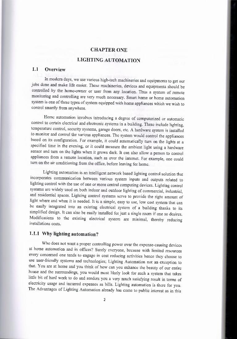
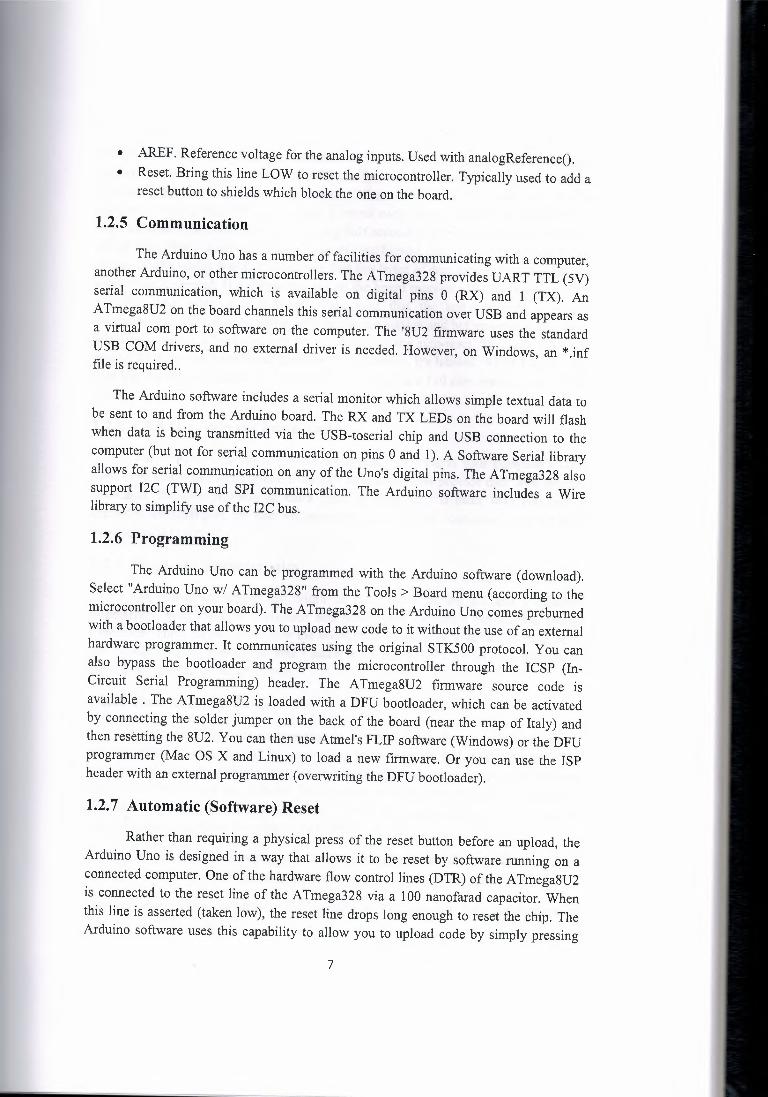
A light-emitting diode commonly called LED is a two-lead semiconductor light source that resembles a basic pn-junction diode, except that an LED also emits light. When an LED's anode lead has a voltage that is more positive than its cathode lead by at least the LED's forward voltage drop, current flows. Electrons are able to recombine with holes within the device, releasing energy in the form of photons. This effect is called electroluminescence, and the color of the light ( corresponding to the energy of the photon) is determined by the energy band gap of the semiconductor.
Basically, LEDs are just tiny light bulbs that fit easily into an electrical circuit. But unlike ordinary incandescent bulbs, they don't have a filament that will burn out, and they don't get especially hot. They are illuminated solely by the movement of electrons in a semiconductor material, and they last just as long as a standard transistor. The lifespan of an LED surpasses the short life of an incandescent bulb by thousands of hours. An LED is often small in area (less than 1 mm2), and integrated optical components may be used to shape its radiation pattern.
A diode is the simplest sort of semiconductor device. Broadly speaking, a semiconductor is a material with a varying ability to conduct electrical current. Most semiconductors are made of a poor conductor that has had impurities (atoms of another material) added to it. The process of adding impurities is called doping.
In the case of LEDs, the conductor material is typically aluminum-gallium arsenide (AlGaAs). In pure aluminum-gallium-arsenide, all of the atoms bond perfectly to their neighbors, leaving no free electrons (negatively charged particles) to conduct electric current. In doped material, additional atoms change the balance, either adding free electrons or creating holes where electrons can go. Either of these alterations make the material more conductive.
A semiconductor with extra electrons is called N-type material, since it has extra negatively charged particles. In N-type material, free electrons move from a negatively charged area to a positively charged area.
A semiconductor with extra holes is called P-type material, since it effectively has extra positively charged particsles. Electrons can jump from hole to hole, moving from a negatively charged area to a positively charged area. As a result, the holes themselves appear to move from a positively charged area to a negatively charged area.
10
\,
Anode
Figure 1.3 Light Emitting Diode
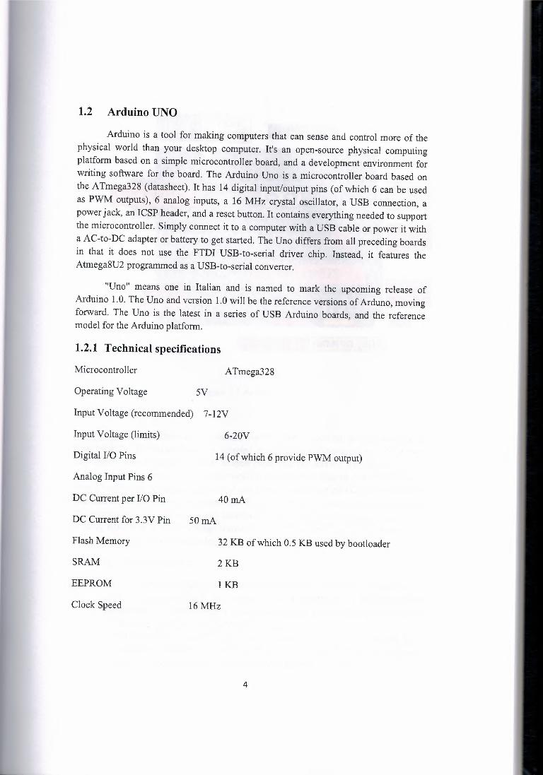
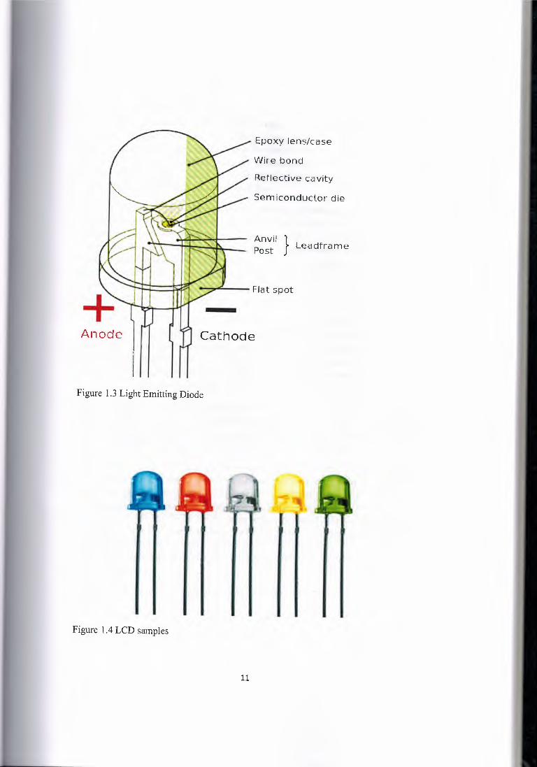
Figure 1.4 LCD samples
Epoxy lens/case
Wire bond
Reflective cavity
Semiconductor die
Anvil }• Leadframe Post .
Cathode
11
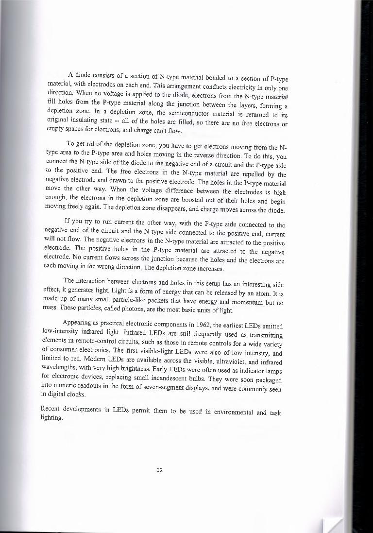
A diode consists of a section of N-type material bonded to a section of P-type material, with electrodes on each end. This arrangement conducts electricity in only one direction. When no voltage is applied to the diode, electrons from the N-type material fill holes from the P-type material along the junction between the layers, forming a depletion zone. In a depletion zone, the semiconductor material is returned to its original insulating state -- all of the holes are filled, so there are no free electrons or empty spaces for electrons, and charge can't flow.
To get rid of the depletion zone, you have to get electrons moving from the N type area to the P-type area and holes moving in the reverse direction. To do this, you connect the N-type side of the diode to the negative end of a circuit and the P-type side to the positive end. The free electrons in the N-type material are repelled by the negative electrode and drawn to the positive electrode. The holes in the P-type material move the other way. When the voltage difference between the electrodes is high enough, the electrons in the depletion zone are boosted out of their holes and begin moving freely again. The depletion zone disappears, and charge moves across the diode.
If you try to run current the other way, with the P-type side connected to the negative end of the circuit and the N-type side connected to the positive end, current will not flow. The negative electrons in the N-type material are attracted to the positive electrode. The positive holes in the P-type material are attracted to the negative electrode. No current flows across the junction because the holes and the electrons are each moving in the wrong direction. The depletion zone increases.
The interaction between electrons and holes in this setup has an interesting side effect, it generates light. Light is a form of energy that can be released by an atom. It is made up of many small particle-like packets that have energy and momentum but no mass. These particles, called photons, are the most basic units of light.
Appearing as practical electronic components in 1962, the earliest LEDs emitted low-intensity infrared light. Infrared LEDs are still frequently used as transmitting elements in remote-control circuits, such as those in remote controls for a wide variety of consumer electronics. The first visible-light LEDs were also of low intensity, and limited to red. Modem LEDs are available across the visible, ultraviolet, and infrared wavelengths, with very high brightness. Early LEDs were often used as indicator lamps for electronic devices, replacing small incandescent bulbs. They were soon packaged into numeric readouts in the form of seven-segment displays, and were commonly seen in digital clocks.
Recent developments in LEDs permit them to be used in environmental and task lighting.
12
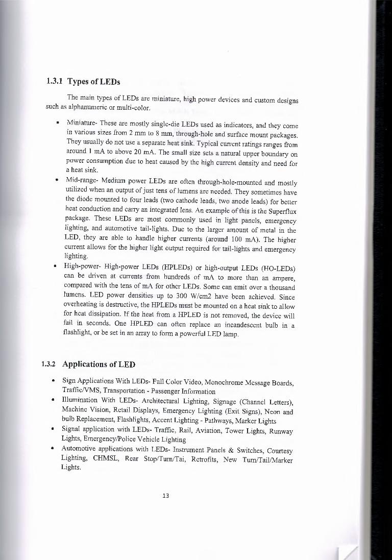
1.3.1 Types of LEDs
The main types of LEDs are miniature, high power devices and custom designs such as alphanumeric or multi-color.
• Miniature- These are mostly single-die LEDs used as indicators, and they come in various sizes from 2 mm to 8 mm, through-hole and surface mount packages. They usually do not use a separate heat sink. Typical current ratings ranges from around 1 mA to above 20 mA. The small size sets a natural upper boundary on power consumption due to heat caused by the high current density and need for a heat sink.
• Mid-range- Medium power LEDs are often through-hole-mounted and mostly utilized when an output of just tens of lumens are needed. They sometimes have the diode mounted to four leads (two cathode leads, two anode leads) for better heat conduction and carry an integrated lens. An example of this is the Superflux package. These LEDs are most commonly used in light panels, emergency lighting, and automotive tail-lights. Due to the larger amount of metal in the LED, they are able to handle higher currents (around 100 mA). The higher current allows for the higher light output required for tail-lights and emergency lighting.
• High-power- High-power LEDs (HPLEDs) or high-output LEDs (HO-LEDs) can be driven at currents from hundreds of mA to more than an ampere, compared with the tens of mA for other LEDs. Some can emit over a thousand lumens. LED power densities up to 300 W/cm2 have been achieved. Since overheating is destructive, the HPLEDs must be mounted on a heat sink to allow for heat dissipation. If the heat from a HPLED is not removed, the device will fail in seconds. One HPLED can often replace an incandescent bulb in a flashlight, or be set in an array to form a powerful LED lamp.
1.3.2 Applications of LED
• Sign Applications With LEDs- Full Color Video, Monochrome Message Boards, TrafficNMS, Transportation - Passenger Information
• Illumination With LEDs- Architectural Lighting, Signage (Channel Letters), Machine Vision, Retail Displays, Emergency Lighting (Exit Signs), Neon and bulb Replacement, Flashlights, Accent Lighting - Pathways, Marker Lights
• Signal application with LEDs- Traffic, Rail, Aviation, Tower Lights, Runway Lights, Emergency/Police Vehicle Lighting
• Automotive applications with LEDs- Instrument Panels & Switches, Courtesy Lighting, CHMSL, Rear Stop/Tum/Tai, Retrofits, New Tum/Tail/Marker Lights.
13

• Consumer Electronics & General Indication- Household appliances, VCR/ DVD/ Stereo/AudioNideo devices, Toys/Games Instrumentation, Security Equipment, Switches.
• Mobile Applications With LEDs- Mobile Phone, PDA's, Digital Cameras, Lap Tops, General Backlighting
• Photo Sensor Applications With LEDs- Medical Instrumentation, Bar Code Readers, Color & Money Sensors, Encoders, Optical Switches, Fiber Optic Communication etc.
1.3.3 Advantages
• Carbon emissions: LEDs deliver significant reductions in carbon emissions. • Efficiency: LEDs emit more lumens per watt than incandescent light bulbs. The
efficiency of LED lighting fixtures is not affected by shape and size, unlike fluorescent light bulbs or tubes.
• Color: LEDs can emit light of an intended color without using any color filters as traditional lighting methods need. This is more efficient and can lower initial costs.
• Size: LEDs can be very small (smaller than 2 mm square) and are easily attached to printed circuit boards.
• On/Off time: LEDs light up very quickly. A typical red indicator LED will achieve full brightness in under a microsecond. LEDs used in communications devices can have even faster response times.
• Cycling: LEDs are ideal for uses subject to frequent on-off cycling, unlike fluorescent lamps that fail faster when cycled often, or HID lamps that require a long time before restarting.
• Dimming: LEDs can very easily be dimmed either by pulse-width modulation or lowering the forward current. This pulse-width modulation is why LED lights viewed on camera, particularly headlights on cars, appear to be flashing or flickering. This is a type of stroboscopic effect.
• Cool light: In contrast to most light sources, LEDs radiate very little heat in the form of IR that can cause damage to sensitive objects or fabrics. Wasted energy is dispersed as heat through the base of the LED.
• Slow failure: LEDs mostly fail by dimming over time, rather than the abrupt failure of incandescent bulbs.
• Lifetime: LEDs can have a relatively long useful life. One report estimates 35,000 to 50,000 hours of useful life, though time to complete failure may be longer. Fluorescent tubes typically are rated at about 10,000 to 15,000 hours, depending partly on the conditions of use, and incandescent light bulbs at 1,000 to 2,000 hours.
14

• Shock resistance: LEDs, being solid-state components, are difficult to damage with external shock, unlike fluorescent and incandescent bulbs which are fragile.
• Focus: The solid package of the LED can be designed to focus its light. Incandescent and fluorescent sources often require an external reflector to collect light and direct it in a usable manner.
1.3.4 Disadvantages
• High initial price: LEDs are currently more expensive, price per lumen, on an initial capital cost basis, than most conventional lighting technologies. As of 2010, the cost per thousand lumens (kilolumen) was about $18. The price is expected to reach $2/kilolumen by 2015. The additional expense partially stems from the relatively low lumen output and the drive circuitry and power supplies needed.
• Temperature dependence: LED performance largely depends on the ambient temperature of the operating environment or "thermal management" properties. Over-driving an LED in high ambient temperatures may result in overheating the LED package, eventually leading to device failure. An adequate heat sink is needed to maintain long life. This is especially important in automotive, medical, and military uses where devices must operate over a wide range of temperatures, which require low failure rates.
• Voltage sensitivity: LEDs must be supplied with the voltage above the threshold and a current below the rating. This can involve series resistors or current regulated power supplies,
• Light quality: Most cool-white LEDs have spectra that differ significantly from a black body radiator like the sun or an incandescent light. The spike at 460 nm and dip at 500 nm can cause the color of objects to be perceived differently under cool-white LED illumination than sunlight or incandescent sources.
• Area light source: Single LEDs do not approximate a point source of light giving a spherical light distribution, but rather a lambertian distribution. So LEDs are difficult to apply to uses needing a spherical light field. However different fields of light can be manipulated by the application of different optics or "lenses". LEDs cannot provide divergence below a few degrees. In contrast, lasers can emit beams with divergences of 0.2 degrees or less.
• Electrical polarity: Unlike incandescent light bulbs, which illuminate regardless of the electrical polarity, LEDs will only light with correct electrical polarity.
• Electric shock hazard: There have been LED recalls because of faulty wiring that can cause electric shock, fire or bums.
• Efficiency drop: The luminous efficacy of LEDs decreases as the electrical current increases above tens of milliamps. Heating also increases with higher currents which compromises the lifetime of the LED. Because of this increased heating, the lighting industry does not exceed 350 mA to power a given LED.
15
1.4 Resistor
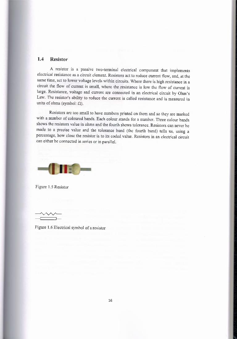
A resistor is a passive two-terminal electrical component that implements electrical resistance as a circuit element. Resistors act to reduce current flow, and, at the same time, act to lower voltage levels within circuits. Where there is high resistance in a circuit the flow of current is small, where the resistance is low the flow of current is large. Resistance, voltage and current are connected in an electrical circuit by Ohm's Law. The resistor's ability to reduce the current is called resistance and is measured in units of ohms (symbol: Q).
Resistors are too small to have numbers printed on them and so they are marked with a number of coloured bands. Each colour stands for a number. Three colour bands shows the resistors value in ohms and the fourth shows tolerance. Resistors can never be made to a precise value and the tolerance band (the fourth band) tells us, using a percentage, how close the resistor is to its coded value. Resistors in an electrical circuit can either be connected in series or in parallel.
Figure 1.5 Resistor
Figure 1.6 Electrical symbol of a resistor
16

The measuring digits against color codes for resistors are given in the following table:
White '91 xlo'9
Gold - x10·1 Silver - x10·2 None
±10%
±5% ±10% ±20%
Figure 1. 7 Resistor colour codes
1.5 Light sensor
A light-dependent resistor (LDR) or photoresistor or photocell is a light controlled variable resistor. The resistance of a photoresistor decreases with increasing incident light intensity; in other words, it exhibits photoconductivity. A photoresistor can be applied in light-sensitive detector circuits, and light- and dark-activated switching circuits. A photoresistor is made of a high resistance semiconductor. In the dark, a photoresistor can have a resistance as high as a few megaohms (MQ), while in the light, a photoresistor can have a resistance as low as a few hundred ohms. If incident light on a photoresistor exceeds a certain frequency, photons absorbed by the semiconductor give bound electrons enough energy to jump into the conduction band. The resulting free electrons (and their hole partners) conduct electricity, thereby lowering resistance. The resistance range and sensitivity of a photoresistor can substantially differ among dissimilar devices.
17
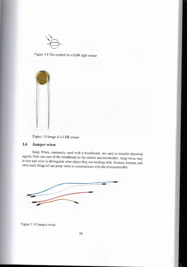
Figure 1.8 The symbol for a LDR light sensor
Figure 1.9 Image of a LDR sensor
1.6 Jumper wires
Jump Wires, commonly used with a breadboard, are used to transfer electrical signals from one part of the breadboard to the central microcontroller. Jump wires vary in size and color to distinguish what object they are working with. Sensors, buttons, and other such things all use jump wires to communicate with the microcontroller.
Figure 1.10 Jumper wires
18
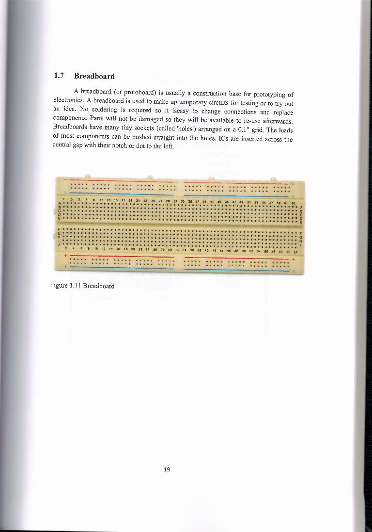
1. 7 Breadboard
A breadboard ( or protoboard) is usually a construction base for prototyping of electronics. A breadboard is used to make up temporary circuits for testing or to try out an idea. No soldering is required so it iseasy to change connections and replace components. Parts will not be damaged so they will be available to re-use afterwards. Breadboards have many tiny sockets ( called 'holes') arranged on a 0.1" grid. The leads of most components can be pushed straight into the holes. ICs are inserted across the central gap with their notch or dot to the left.
+ !J!ili•'•jl ••..•• ~ ••••••• 11t••·· •••.••...••••••...•.. •!•-· •1P:••• •.••• ,, , ••••.•• , ••• ;
:,ii ·~ ••• ~ ••• * • 'ii • -· " • • • .• • • • • iii • Ii
3 .5 7 t 1, 13 15 17 19 ll U 2& t7 tt -31 33 36 37 39 <I 43 •~ <1 •t 51 M M 57 ,t 91 '3 A••••••••••••••••••••••••••••••••••••••••••••••••••••••••••••••••A a•••••••••••••••••••••••••••••••••••••••••••••••••••••••••••••••• e D•••••••••••••••••••••••••••••••••••••••••••••••••••••••••••••••• D o•••••••••••••••••••••••••••••••••••••••••••••••••••••••••••••••• o £~······························································· £
f •·••,,••••••••••·••••••••••••••••••••••••••••••••••·•.••••••••••••••• F G•••••••••••••••••••••••••••••••••••••••••••••••••••••••••••••••• G ,M•••••••••••••••••••••••••••••••••••••••••••••••••••••••••••••••• M I •••••••••••••••••••••••••«·••••••-•••••••••••••••••••--••••••••••ii- J J ••••••••••••.••••••• ,• ••• -· •••••••.•••••••••••••.•••••• -• .••.•.•••••.• '. • • J
•, , e· to 12 u ,a 1t1 20 22 2• 211 tt :io 32 3• 3" :Ill •o u u ,a •• ao s.2 s• Mi u tio 112 i• _
+ ..... ··~·- ····· ..... ..... ~ .....•.•. -~ - •.•........• --
Figure 1.11 Breadboard
19

CHAPTER TWO
Building the lighting control system circuit
This chapter explains the building of this project in a step by step manner. As it is supposed, components or materials needed for a task, in this case a project will be provided and readied to be used. The materials has been discussed earlier in section chapter one. First, i had the matlab program installed on my computer. The major component of this project is obviously the arduino UNO and most of the work will be done on it. The next step is to connect the computer and the arduino. For this project, the arduino will be connected directly to the computer using the arduino USB cable. That doesn't just do it all as communication between the two, that is the computer and the arduino should be established. Before the connection, the arduino environment for the UNO had been downloaded and installed from the arduino web page. Connect the USB to the computer. The arduino UNO draw power from the USB connection to the computer. The green power LED (labelled PWR) should turn on. Windows will begin it's driver installation process and after a few moments, the process will fail. Click on the Start Menu, and open up the Control Panel. While in the Control Panel, navigate to System and Security. Next, click on System. Once the System window is up, open the Device Manager and look under 'Other Devices' for 'Unknown Device'.
#~-iflm-K 't•fl~~,6 •00 Ei1ot1:ttc;thiR.n11!1$ >~Computtr -• ·Q.. D.1k l!l!ri;;u ~ ":. [;iep:l'lrf l'd,p~I'$ f!.~,l;.\\'0/CD-ROM,b,,,,Ji! ~- ~ Humt!t.lnt~rhc~~ts- > C:i;i t?)f ATJi/ilil.A&l (>0!llrQ)te11. ,-..9 H:E!!~,-Elushnstc:o:it'llro!les ·l'::j:1m+.., •••..•••• ~ .0 t'.tj,tU.1.!ifd~
l!$ Mite-,1M.;;h"'P~~i!'l9d~itoe:s :'1-,._-M~totI J) _ft N~m fd.,pt~r,. ,., ~ Ol!iJif d'.Mt:.tt
.-~uA~-~~ :,.;II• J:lf!~~t;.lrifO!lri'ttt~ i:.-CJire<e:--s;cc,i; '~St";.,~ ~, -~~ 'Adco arid 9tW.t" i:M?rdttu
(, ~: Y,ft'fen, dt"/icie:1 _.., l.¥w-i!Ral 5.e1tili_But.Ur.t1etltt1
f Gm.ieric tJS8 ~.ib -i GffHitlfl,J~H;ill
..• r. .. n.-nr llf.A9.!""l'.!··!!!"'c---------------------------------1
Figure 2.1 Device manager window
20

Right click on the "Unknown Device" port and choose the "Update Driver Software" option. Next, choose the "Browse my computer for Driver software" option.
Finally, navigate to and select the Una's driver file, named "ArduinoUNO.inf', located in the "Drivers" folder of the Arduino Software download. Windows will finish up the driver installation from there. After following the appropriate steps for your software install, we are now ready to test your first program with your Arduino board.
Launch the Arduino application, Select the type of Arduino board you're using: Tools> Board > your board type
l' 1~eu,..
! Tuo,,u~ M
~I .~1~ e:t~1
Ar·c:hivitS.11::crt:c.h f..i)C"Enc:oding & R~lo1d, SerHillMIM'likn
lfC1ard
ft,9~~Vlt
Ser,ial Port
.I/ hn 13 bo.:, J/ i:;n."-"~ ae !l
)l.'l't:. l@d • 13,r
l"togtamc"t'lt!t li'um 8D,p,tfa.1.d«
1.~ ~ "''C'1:.'U'P r~~11l'1.,., ••. 1·1:rJ.'J::· 11"·:tc~ 'lll;i'!''tl yr:r1.1 1;-r~~.:s ~ 'il~u-d set . ._,. (J ~
ll in.J.1:1.-eioli,r:,e t:h~ 1i1g:t-ud p.:irt o::, >4r.l oue.j:t!llt~ vu:Z!t:!'1~( 1.e&~ otrrwr,:
v ~:!.-I.! lJ::t41,,1 f ·r--'-"'~·· ..... ·-~ !
Figure 2.2 Selecting your arduino type
ol\_1':NiJJo /1,J/R Uo-Md$1
iY"' AX<!1.{llr.,o Un.o- Ard\lf,io Dt.fEmib~ At<l.U11ilO N'.and A·tdr..iir,,o Megi, 2560 c,;r
Ar{f'(lino r..i.,t.:gn (.ATIT!CS Anch..ii'r,io l<!iet"l,1rdl) ArdUlnr., Mien:, AN:&iimoUp:)c,,.!I
Atid1i:1in0Mir,I
Ardui!l'lo Ethernet AtthuinoFio Ard.um.,;if1T
LityP•dArdy!~\JSS: U}j.•J>.a.d .J'I.Jd~lM At:dumo Pro ,(N (j,o Mil Ardt.1ir,to NG or -e.1~r
Ai-.U•..11'10 AlfJ.,.1 ~1~-b,u) Ard\Jino Due CP'n::t9r11m. Ard.;,ino 0-1" (Ni!!!tW~ V
Select the serial/COM port that your Arduino is attached to: Tools > Port > COMxx. For my computer, the arduino is attached to port COM8.
21

I* 1:tJ..U.lX Turn.,, 1:)11 WI<
Ar.:;;t"iivt.S<'htc:!'<
fit'&1<.tx:lir1g & . Relead Si!rittl Mand.or-
80.ud
f'l'Q~e;'i:'.(ff'
Ser,la! Port
II l'H'l. i.J tt~, 1.1 ,,l't~-?! -u, ft L Uft l~d. m 13;
fllt!.i5Jf:.0MmEI
tk1mBc,Cl.i:a.td«
/,l itn.-· .:"l""T::lX.('l l"DUi'-tT'1f'I l;IU);t &~£" 1.lf;iP'~ Y"'l.1 J;!'Y1'9;:i T"l"l'J~c.: VO~i! :S:f'l:tl!V O {
if J.:ru:t:tol:u::~ the d.-1g:H:.cl. ;tlh. &:! An p:uepu.t.~ '-"iJ:!~d.>2 ~ U::d.)· IJVT1-'i.,"T);
'fl l
Figure 2.3 Serial port window
With the Arduino board connected, and the Blink sketch open, press the 'Upload' button
// r-vi .1., h~, "" t,.'f.'li c(r1wr-;:-r. ••• ,1 ml 'Wl':1t: ,h:~11.t'H"' tea:in:r.t~"'. I/ v,ve ~t: o, ~~!!:
.un; l:~d • 13.;
fl th,. :tf''1::'l.>r' ·t'.OIJ't\D:"" rim;• Mi~,. m:;rn 3'91."l rre-ee r-~-r.c.: ,;;,¢:i,,d: t!r~tw,v, O {
l i ;t.n:i. t?.ttLl~!!:: t:hl:' .d.:t.~1-tel 1:u.n e.~ -sn. ovi~J.t:. J;.'<LI.X-0aa ~ 1 ee, OO't't-'1.IT) :
'') J.i Ut~ lo!:'l) coutuil!: run~ eve e dDtt G'l~T. ~a.:i.a :toz;e-~,,c~: •,..-o'.id. l.ot,t,,J .( .. t·~·~·=·~
Figure 2.4 Blink window
22

After a second, you should see some LEDs flashing on your Arduino, followed by the message 'Done Uploading' in the status bar of the Blink sketch. If everything worked, the onboard LED on my Arduino should now be blinking and i just programmed my first Arduino.
The next step is for me to connect or create a communication between the arduino and matlab. It is done by opening the matlab program and then initializing the arduino on the matlab. I used "s" to initialize as follows:
>> s=arduino('COM8')
Attempting connection .
Arduino successfully connected.
a= arduino object connected to COM8 port
What appears next is a whole lot of Digital unassigned pins and detached servos. Matlab and Arduino are now connected.
The first thing I tried was to turn on and turn off one LED by the following steps:
Connect the long leg of an LED (the positive leg, called the anode) to pin 13 and the short leg (the negative leg, called the cathode) to GND (ground) on the Arduino. The first thing you do is to initialize pin 13 as an output pin with the line code.
>> a.pinmode(13, 'OUTPUT');
You will notice that pin 13 from the long list of unassigned pins will change to currently set as output. Clear the window and type
>>a.digita1Write(13, 1)
To tum on the LED and
>>a.digitalWrite(l 3, 0)
To tum it off as shown in the figure below and that sums it all for getting started.
23

Figure 2.5 Lighting a LED
The next stage is the main phase of the project where all five LEDs will be connected to the breadboard and the arduino. The positives of the LEDs are connected to pins 2,3,4,5 and 6 on the arduino and their negatives on a common ground on the breadboard and then a jumper cable connects the GND on the board to the GND on the arduino. We initialize all 5 pins as output pins as shown
>> a.pinmode(_, 'OUTPUT');
And then assign
>>a.digitalWrite(_, 1)
>>a.digitalWrite(_, 0)
for all the pins as shown above to turn on and tum off the LEDs.
So far, everything is controlled manually. For the automatic control of the LEDs, special codes were deployed for the illumination. The automatic control is solely dependent on the LDR.
For the LDR (light sensor), conditional statements is used. Its main MATLAB code is the
>> analogRead.
The analogRead measures the light intensity of the surrounding environment and the sensor will perform as has been programmed to. In this project, the light intensity is set at 200 lumen. If the light intensity measures below 200 lumen, the automatic mode will be activated and the LEDs will turn on and will turn off when the sensor measures intensity higher than the set value. A time delay of 30 seconds was set for tum off. That is, it will delay for 30 seconds before turn off when the intensity is high.
24

The negative end of the LDR is connected to one end of a resistor (lkn of resistance) and the other end of the resistor is connected to GND on the arduino. The positive end of the sensor is connected to 5V on the arduino and the joint end of both the sensor and the resistor are connected to pin A5 (it can be any of the pins AO-to-A5). The essence of the resistor is to divide the voltage between 5V and GND.
1 : • • •• • l3 • . • " ..
fOf.tf:.t flEfiE'f ) :?ii r--:--:j..J~ ONO V"I f ··llil
'rt?J . ,,,...,,, ... *
(0 rx f<)\
~-· R~&1~1·e1.,., "'f,'.:; ~
Figure 2.6 Schematic diagram of the project
25

Figure 2.7 Project circuit setup
The LEDs on the prototype are placed under the above image. They are descending just as bulbs are placed on the roof in a room.
26
CHAPTER THREE
The Graphical User Interface (GUI)
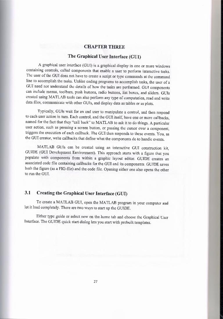
A graphical user interface (GUI) is a graphical display in one or more windows containing controls, called components that enable a user to perform interactive tasks. The user of the GUI does not have to create a script or type commands at the command line to accomplish the tasks. Unlike coding programs to accomplish tasks, the user of a GUI need not understand the details of how the tasks are performed. GUI components can include menus, toolbars, push buttons, radio buttons, list boxes, and sliders. GUis created using MATLAB tools can also perform any type of computation, read and write data files, communicate with other GUis, and display data as tables or as plots.
Typically, GUis wait for an end user to manipulate a control, and then respond to each user action in tum. Each control, and the GUI itself, have one or more callbacks, named for the fact that they "call back" to MATLAB to ask it to do things. A particular user action, such as pressing a screen button, or passing the cursor over a component, triggers the execution of each callback. The GUI then responds to these events. You, as the GUI creator, write callbacks that define what the components do to handle events.
MATLAB GUis can be created using an interactive GUI construction kit, GUIDE (GUI Development Environment). This approach starts with a figure that you populate with components from within a graphic layout editor. GUIDE creates an associated code file containing callbacks for the GUI and its components. GUIDE saves both the figure (as a FIG-file) and the code file. Opening either one also opens the other to run the GUI.
3.1 Creating the Graphical User Interface (GUI)
To create a MATLAB GUI, open the MATLAB program in your computer and let it load completely. There are two ways to start up the GUIDE.
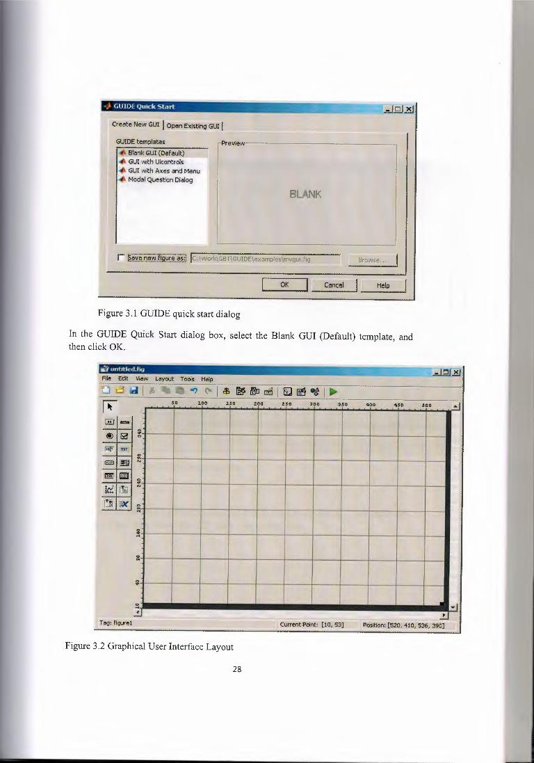
Either type guide or select new on the home tab and choose the Graphical User Interface. The GUIDE quick start dialog lets you start with prebuilt templates.
27
~ •.. ··--······-··----~·~-- ....••• . -~- -·-~ --- -....-.._ - -- } GUIDE Quick Start ·f;;:,
GUIDE templates
~ Bla~.§UIJ[?ef~lt) 11 ••• GUI ;111ith Uicontrols '4l GUI with Axes and Menu ,II. Modal Question Dialog
BLANK
BtO'l/Se.,.
~l' Cancel
Figure 3.1 GUIDE quick start dialog
In the GUIDE Quick Start dialog box, select the Blank GUI (Default) template, and then click OK.
- -·-,===--~- • un e .fig ~u:~
~ .. ~ .. :
?~ ~
~
0 •. ~
Figure 3.2 Graphical User Interface Layout
28

Select File > Preferences > GUIDE. Select Shows names in component palette. Click OK.
J.00 J.50 too 250 300 350 400
~ . ~
1:'.]i; Button Group /~ ActiveX Control
Figure 3.3 GUIDE Preference pallete
Set the size of the GUI by resizing the grid area in the Layout Editor. Click the lower right comer and drag it until the GUI takes your desired size.
29

~-----1~1 I
ft-S~i!<!
GlPush:!!Woa
liJ Chedit Bat I S1 ' ' I ftili £dtfe:rt
. I I ,, I I I l·-,----1 ·. . . I I
Click ind d~
Figure 3 .4 Resizing the GUIDE layout
The GUI has seven radio buttons. Five for the LEDs and the other two for the automatic and manual control. It also has three press buttons for the Run, stop and switch lights. The run button connects the program to the Arduino and the stop button disconnects it. The switch lights button turns on or turns off all the LEDs at once. The design depends on how the user wants it.
To add the buttons to the GUI, select the button tool from the component palette at the left side of the Layout Editor and drag it into the layout area to your desired position. Right click on the placed button and a dialog where you can duplicate will pop up. Clicking on duplicate will create identical buttons. Repeat this process to get the number of buttons needed. Add the remaining components to the GUI. Adding a panel groups buttons together. Click panel, click on the layout and drag the mouse to cover all the buttons you wish to group. Panel makes the arrangement of grouped buttons easier. For instance, in this project the five LEDs, the automatic and manual control and the run and stop buttons were panelled. Several components of the GUI have the same parent, therefore we used the Alignment Tool to align them to one another by Selecting Tools> Align Objects.
To label the buttons and panels, select View > Property Inspector and the inspector dialog will pop up.
30

6Ut't0110ownf\cn
Clipping
Clo~equestFcn lrB; Co106' l ,C;e~Fcn
on
dosere,:i -~ CJ
CutrenKharact.er ! @lcurrentPolnt · ·- ·
le,.tefcn
,ck.Controls ~~-=~
0 ----- .. --- - -·--- _.., __
on T,...,.
Figure 3.5 GUIDE inspector dialog
On the layout area, click on a button and select the String property in the Property Inspector and type in your desired label for the button and press enter. This automatically names your button. To name or label the panels, click on the panel and select the title property and then type in your desired label.
SelecoonHigl:ild,t on • · •. - - ttl1 ShdetStep [0,01 0,1]
~f Surf Stnng
Style pushbutton ;bl
Figure 3.6 String function
Save the GUI Layout. When you save a GUI, GUIDE creates two files, a FIG file and a code file. The FIG-file, with extension .fig, is a binary file that contains a description of the layout. The code file, with extension .m, contains MATLAB functions that control the GUI behaviour. Save and activate your GUI by selecting Tools > Run. GUIDE displays a dialog box displaying: Activating will save changes to your figure file and MATLAB code. Do you wish to continue? Click Yes. GUIDE opens a Save As dialog box in your current folder and prompts you for a FIG-file name. Browse to any folder for which you have write privileges, and then enter the file name for the FIG-file. GUIDE saves both the FIG-file and the code file using this name. If the folder in which you save the GUI is not on the MATLAB path, GUIDE opens a dialog
31

box, giving you the option of changing the current folder to the folder containing the GUI files, or adding that folder to the top or bottom of the MATLAB path. GUIDE saves the files and then activates the GUI. It also opens the GUI code file in your default editor. The GUI opens in a new window. Below is an image of the GUI as an executable .exe file.
Illumination-------------,
11 LED1 } LED 2
' Lffil LED4 Stop
Swltcil (Light) LEDS.
Figure 3. 7 Graphical user interface
To run a GUI created with GUIDE without opening GUIDE, execute its code file by typing its name.
The next line of action shows how to control the LEDs when the GUI user clicks a button. The opening function generates this data by calling MATLAB functions. The opening function, which initializes a GUI when it opens, is the first callback in every GUIDE-generated GUI code file.
For this project, you add codes that turn the LEDs on or off and also measures the intensity of light to the opening function. The code uses the MATLAB functions pinMode, digitalWrite, and analogRead. Display the opening function in the MATLAB Editor. If the projects m-file is not already open in the editor, open from the layout Editor by selecting view> Editor. I saved the project as illumination. On the EDITOR tab, in the NA VI GATE section, click Go To, and then select illumination_ OpeningFcn. The cursor moves to the opening function, which contains this code:
% --- Executes just before illumination is made visible.
function simple _gui_ OpeningF cn(hObj ect, eventdata, handles, varargin)
% This function has no output args, see OutputFcn.
% hObject handle to figure
% eventdata reserved - to be defined in a future version of MATLAB
32

% handles structure with handles and user data (see GUIDATA)
% varargin command line arguments to illumination (see V ARARGIN)
% Choose default command line output for simple _gui
handles.output== hObject;
% Update handles structure
guidata(hObject, handles);
% UIWAIT makes illumination wait for user response (see UIRESUME)
% uiwait(handles.figure 1 );
Create data for the GUI to perform the task by adding the MATLAB codes to the opening function immediately after the comment that begins % varargin ...
They store the data in the handles structure, an argument provided to all callbacks. Callbacks for the push buttons can retrieve the data from the handles structure. Right clicking on the buttons of the GUI in the editor shows the layout to assign the callbacks. Save your code by selecting File > Save. Run your GUI from the Layout Editor by selecting Tools> Run.
33

3.2 Creating an executable file for the graphical user interface on MATLAB
The essence of creating an executable .exe file is basically to run the program independently of MATLAB. There are different ways of creating an executable .exe file for the graphical user interface on MATLAB. The MATLAB compiler software must have been installed in the computer.
3.2.1 Instructions
• Open the compiler software and select a new deployment from the File tab on the main menu or from toolbar icons. Then, to create an .exe file, choose to create a Windows Standalone Application.
• Add files to the new, but now empty project. Start by clicking "Edit: Add: Files" from the main menu or click the "Add Files" icon and then navigate to the location where you saved the MATLAB file you want to compile. Select the appropriate MATLAB file and click "Add File." The compiler will add the MATLAB file to your previously empty project.
• Build the project by selecting Project: Build Project from the main menu or by selecting the Build icon. The compiler will complete the necessary steps behind the-scenes to create the .exe and other necessary files, two subfolders - a source and a distribution folder - and place everything in the project folder in your MATLAB working directory.
• Open the project distribution folder by double-clicking first on the main project folder and then on the distribution folder. The distribution folder will contain your new .exe file.
• Rename the .exe file by changing it from "untitled.exe" to a more appropriate name. Make sure to change only the "untitled" portion of the name, leaving the .exe portion as-is.
A sample image of an executable file from the graphic user interface on MATLAB is shown in Figure 3.7.
34

3.3 M-FILE CODES
Below is the whole program code on the MATLAB m-file window for this project:
function varargout = Illumination(varargin) % ILLUMINATION MATLAB code for Illumination.fig % ILLUMINATION, by itself, creates a new ILLUMINATION or raises the existing % singleton*. % % H = ILLUMINATION returns the handle to a new ILLUMINATION or the handle to % the existing singleton*. % % ILLUMINATION('CALLBACK',hObject,eventData,handles, ... ) calls the local % function named CALLBACK in ILLUMINATION.M with the given input arguments. % % ILLUMINATION('Property','Value', ... ) creates a new ILLUMINATION or raises the % existing singleton*. Starting from the left, property value pairs are % applied to the GUI before Illumination_ OpeningF en gets called. An % unrecognized property name or invalid value makes property application % stop. All inputs are passed to Illumination_ OpeningF en via varargin. % % *See GUI Options on GUIDE's Tools menu. Choose "GUI allows only one % instance to run (singleton)". % % See also: GUIDE, GUIDATA, GUIHANDLES
% Edit the above text to modify the response to help Illumination
% Last Modified by GUIDE v2.5 13-May-2014 12:29:58
% Begin initialization code - DO NOT EDIT gui_Singleton = l; gui State = struct('gui_Name', mfilename, ...
'gui_Singleton', gui_Singleton, ... 'gui_OpeningFcn', @Illumination_OpeningFcn, ... 'gui_ OutputFcn', @Illumination_ OutputFcn, ... 'gui_LayoutFcn', [] , ... 'gui_ Callback', []);
if nargin && ischar( varargin { 1}) gui_ State.gui_ Callback= str2func(varargin { 1} );
end
ifnargout [varargout{l :nargout} J = gui_mainfcn(gui_State, varargin {:} );
else gui_mainfcn(gui_State, varargin {:} );
35

end % End initialization code - DO NOT EDIT
% --- Executes just before Illumination is made visible. function Illumination_ OpeningFcn(hObject, eventdata, handles, varargin) % This function has no output args, see OutputFcn. % hObject handle to figure % eventdata reserved- to be defined in a future version of MATLAB % handles structure with handles and user data (see GUIDATA) % varargin command line arguments to Illumination (see V ARARGIN)
% Choose default command line output for Illumination handles.output= hObject;
% Update handles structure guidata(hObject, handles);
% UIWAIT makes Illumination wait for user response (see UIRESUME) % uiwait(handles.figurel);
% --- Outputs from this function are returned to the command line. function varargout = Illumination_OutputFcn(hObject, eventdata, handles) % varargout cell array for returning output args (see V ARARGOUT); % hObject handle to figure % eventdata reserved - to be defined in a future version of MATLAB % handles structure with handles and user data (see GUIDATA)
% Get default command line output from handles structure varargout { 1} = handles. output;
% --- Executes on button press in 11. function 11 _ Callback(hObject, eventdata, handles) % hObject handle to 11 (see GCBO) % eventdata reserved - to be defined in a future version of MATLAB % handles structure with handles and user data (see GUIDATA)
% Hint: get(hObject,'Value') returns toggle state ofll globals val=get(hObject,'value'); s.pinMode(2,'output'); ifval==l
s.digita1Write(2, 1 ); else
s.digita1Write(2,0); end % --- Executes on button press in 12.
36

function 12 _ Callback(hObject, eventdata, handles) % hObject handle to 12 (see GCBO) % eventdata reserved - to be defined in a future version of MATLAB % handles structure with handles and user data (see GUIDATA)
% Hint: get(hObject,'Value') returns toggle state ofl2 globals val=get(hObj ect, 'value'); s.pinMode(3,'output'); ifval==l
s.digita!Write(3, 1 ); else
s.digita!Write(3,0); end
% --- Executes on button press in 15. function 15 Callback(hObject, eventdata, handles) % hObject handle to 15 (see GCBO) % eventdata reserved- to be defined in a future version of MATLAB % handles structure with handles and user data (see GUIDATA)
% Hint: get(hObject,'Value') returns toggle state ofl5 globals val=get(hObj ect, 'value'); s.pinMode(6,'output'); ifval==l
s.digita!Write( 6, 1 ); else
s.digita!Write( 6,0); end
% --- Executes on button press in 14. function 14_ Callback(hObject, eventdata, handles) % hObject handle to 14 (see GCBO) % eventdata reserved - to be defined in a future version of MATLAB % handles structure with handles and user data (see GUIDATA)
% Hint: get(hObject,'Value') returns toggle state ofl4 globals val=get(hObject,'value'); s.pinMode(5,'output'); ifval==l
s.digita!Write(5, 1 ); else
s.digita!Write(5,0); end
% --- Executes on button press in 13. function 13 Callback(hObject, eventdata, handles)
37

% hObject handle to 13 (see GCBO) % eventdata reserved - to be defined in a future version of MATLAB % handles structure with handles and user data (see GUIDATA)
% Hint: get(hObject,'Value') returns toggle state ofl3 globals val=get(hObject,'value'); s.pinMode( 4,'output'); ifval==l
s.digitalWrite( 4, 1 ); else
s.digitalWrite( 4,0); end
% --- Executes on button press in 16. function 16 _ Callback(hObject, eventdata, handles) % hObject handle to 16 (see GCBO) % eventdata reserved - to be defined in a future version of MATLAB % handles structure with handles and user data (see GUIDATA)
% Hint: get(hObject,'Value') returns toggle state ofl6 globals val=get(hObj ect, 'value'); s.pinMode(7,'output'); ifval==l
s.digita1Write(7, 1 ); else
s.digita1Write(7,0); end
% --- Executes on button press in run. function run Callback(hObject, eventdata, handles) % hObject handle to run (see GCBO) % eventdata reserved - to be defined in a future version of MATLAB % handles structure with handles and user data (see GUIDATA) globals s=arduino('COM8'); set(handles.stop,'enable','on'); set(handles.run,'enable','off); set(handles.ma,'enable','on'); set(handles.auto,'enable','on');
% --- Executes on button press in stop. function stop_ Callback(hObject, eventdata, handles) % hObject handle to stop (see GCBO) % eventdata reserved - to be defined in a future version of MATLAB % handles structure with handles and user data (see GUIDATA) globals set(handles.ma, 'value', 1);
38

set(handles.auto,'value',O); delete(s); set(handles.run,'enable','on'); set(handles.stop, 'enable',' off'); set(handles.ma,'enable','off'); set(handles.auto,'enable','off');
% --- Executes on button press in ma. function ma_Callback(hObject, eventdata, handles) % hObject handle to ma (see GCBO) % eventdata reserved - to be defined in a future version of MATLAB % handles structure with handles and user data (see GUIDATA)
% Hint: get(hObject,'Value') returns toggle state ofma globals ma=get(hObj ect, 'value'); ifma==l
set(handles.auto,'value',O); end set(handles.11, 'value',O, 'enable','on'); set(handles.12, 'value', 0, 'enable', 'on'); set(handles.13, 'value', 0, 'enable',' on'); set(handles.14, 'value', 0, 'enable',' on'); set(handles.15, 'value', 0, 'enable', 'on'); set(handles.16, 'value', 0, 'enable',' on'); set(handles.tum,'enable','on');
% --- Executes on button press in tum. function tum_ Callback(hObject, eventdata, handles) % hObject handle to turn (see GCBO) % eventdata reserved - to be defined in a future version of MATLAB % handles structure with handles and user data (see GUIDATA)
% Hint: get(hObject,'Value') returns toggle state of tum globals set(handles.11,'value', 1, 'enable', 'on'); set(handles.12, 'value', 1,'enable', 'on'); set(handles.13,'value', 1, 'enable', 'on'); set(handles.14,'value', l ,'enable','on'); set(handles.15,'value', 1, 'enable', 'on'); set(handles.16,'value', 1,'enable', 'on'); set(handles.tum,'enable','on'); for i=2:7 s. pinMode(i, 'output'); s.digitalWrite(i, 1 ); end
39

% --- Executes on button press in auto. function auto_Callback(hObject, eventdata, handles) % hObject handle to auto (see GCBO) % eventdata reserved - to be defined in a future version of MATLAB % handles structure with handles and user data (see GUIDATA)
% Hint: get(hObject,'Value') returns toggle state of auto global s auto auto=get(h Object, 'value'); if auto==l set(handles.ma,'value',O); set(handles.11, 'value', 0, 'enable',' off); set(handles.12, 'value', 0, 'enable',' off); set(handles.13, 'value', 0, 'enable', 'off); set(handles.14, 'value', 0, 'enable', 'off); set(handles.15, 'value', 0, 'enable',' off); set(handles.16, 'value', 0, 'enable',' off); set(handles.tum,'enable','off); for j=2:7 s.pinMode(j ,'output'); s.digitalWrite(j ,O); end while(l)
denval=s.analogRead( 5); if denval > 200
for i=2:6 s. pinMode( i, 'output'); s.digitalWrite(i,O); end
elseif denval < 200 for i=2:6 s. pinMode( i, 'output'); s.digitalWrite(i, 1 ); end
end pause(30)
end end
40
CONCLUSION
In conclusion, lighting automation is a sustainable solution to lighting related tasks that enable the users to have superior control over lighting and also to cut the costs regarding usage of electricity to a greater extent. This low cost system is designed to improve the standard of living in homes.
The lighting automation can also be controlled wirelessly using Bluetooth connection, web or internet, mobile phones etc.
As days go by, lighting automation would get more and more advanced and render more sustainable lighting solutions which also will enhance the advantages of lighting automation to a greater extent.
However, high initial and maintenance costs, the apparent complexity of these systems, and concerns about the interoperability of lighting systems have limited such applications.
41
REFERENCES
[1]. http://www.ehow.com/how _ l 2187066 _ create-exe-file-gui-matlab.html
[2]. http://www.ashoksmatlab.blogspot.com
[3]. http://arduino.cc/en/guide/windows
[ 4]. http ://www.mathworks.com/videos/ creating-a-gui-with-guide-68979 .html
[5]. http://blogs.mathworks.com/videos/category/gui-or-guide/
[ 6]. http://en.wikipedia.org/wiki/Lighting_ control_ system
42