nd ltd iti dnanodroplet deposition and manipulation with ... · nd ltd iti dnanodroplet deposition...
TRANSCRIPT

N d l t d iti dNanodroplet deposition and manipulation with an AFM tipmanipulation with an AFM tip
Laure Fabié, Hugo Durou, Thierry Ondarçuhu
Nanosciences Group, CEMES‐CNRS Toulouse (France)

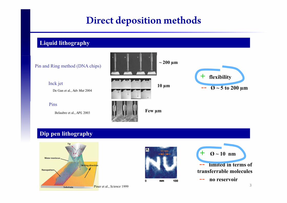
Direct deposition methods
Liquid lithography
+ flexibility
Pin and Ring method (DNA chips)~ 200 µm
flexibility
-- Ø ~ 5 to 200 µmInck jet
De Gan et al., Adv Mat 200410 µm
Pins
Belaubre et al., APL 2003 Few µm
Dip pen lithography
+ Ø ~ 10 nm
-- limited in terms of transferrable molecules
2
transferrable molecules-- no reservoir
Piner et al., Science 1999
Direct deposition methods
Liquid lithography
+ flexibility
Pin and Ring method (DNA chips)~ 200 µm
flexibility
-- Ø ~ 5 to 200 µmInck jet
De Gan et al., Adv Mat 200410 µm
Pins
Belaubre et al., APL 2003 Few µm
Dip pen lithography
+ Ø ~ 10 nm
-- limited in terms of transferrable molecules
3
transferrable molecules-- no reservoir
Piner et al., Science 1999

NADIS : Liquid NAnoDISpensing
Meister et al, Appl. Phys. Lett. 2004A.Fang, E. Dujardin, T.Ondarçuhu, NanoLett 2006
4

Tip fabrication
Standard AFM tip: pyramidal and gold coatedChannel milling by FIB
2 steps : (i) thinning of the tip wall from the top (ii) milling at the tip apex from the tip side (record : 35 nm)
1 2
100 nm251 nm
35 nm100 nm
Surface functionnalisation
500 nm251 nm
Surface functionnalisation
Intact gold layer(thiol chemistry)
2 distinct areas : Si3N4 surface for silane chemistry and gold layer for thiol treatment

Tip loading
Deposited liquid
Glycerol or glycerol-water mixture (dilution max 6:4)Solutions of molecules, proteins, nanoparticles…
Loading of the reservoir
ReservoirReservoir
10µm 10µm10µm
6
Drop deposited with a micropipetteand a micromanipulator
micropipette

Deposition process
Nanodroplet deposition : with an AFM in
Deposition
Nanodroplet deposition : with an AFM inforce spectroscopy mode
Line deposition : with an AFM in contactpmode and using a nanopositioning table
7

Deposition process
Nanodroplet deposition : with an AFM in
Deposition
Nanodroplet deposition : with an AFM inforce spectroscopy mode
Line deposition : with an AFM in contactpmode and using a nanopositioning table
Force curve recorded during liquid transfert
8

Deposition process
Nanodroplet deposition : with an AFM in
Deposition
Nanodroplet deposition : with an AFM inforce spectroscopy mode
Line deposition : with an AFM in contactpmode and using a nanopositioning table
Deposit observation (after solvent evaporation)
Force curve recorded during liquid transfert
9

Nanodroplet deposition
Hydrophilic tip with an aperture of 400nm
Ø ~ 75nm1 µmµ
Hydrophobic tip with an aperture of 35nm(treated with dodecanethiol)(treated with dodecanethiol)
500
10
500nm
The influence of the different parameters is studed in : A. Fang, E. Dujardin, T.Ondarçuhu. NanoLett (2006)
1 µm

Flexibility of the method
25 nm PS NPs DsRed Proteins Ruthenium complexes
1 µm
1µm
5µm
1 µm
5µm
11

Nanopatterning conclusion
1 zL=10-21L
1 aL=10-18L
1 fL=10-15L
1 pL=10-12L
1 nL=10-9L
1 µL=10-6L
10 nm
=10 21L
100 nm
=10 18L
1 μm
=10 15L
10 μm
=10 12L
100 μm
=10 9L
1 mm
=10 6L
12

Study of the deposition mechanisms
Final deposits due to :
flow through the channel
spreading on the substrate surface
13
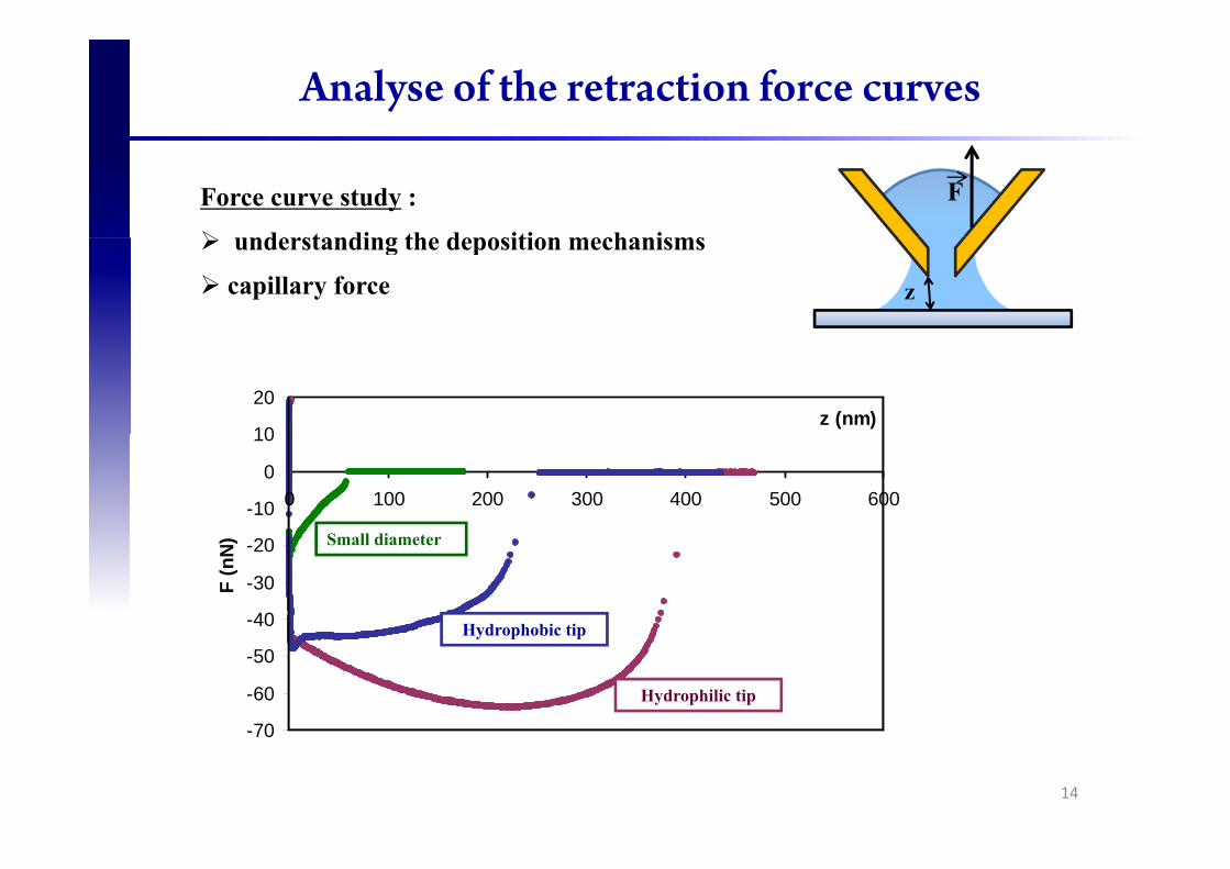
Analyse of the retraction force curves
Force curve study :
nderstanding the deposition mechanisms
F
understanding the deposition mechanisms
capillary force z
10
20z (nm)
-10
0
10
0 100 200 300 400 500 600
S i
-40
-30
-20
F (n
N)
Hydrophobic tip
Small diameter
70
-60
-50
Hydrophilic tip
Hydrophobic tip
-70
14

Modeling with Surface Evolver
Energy minimization for different boundary conditions and constraintsgy y
Pressure and volume
Contact radii and anglesf h• surface shape
• Energy• Pressure• Volume
15
• Force
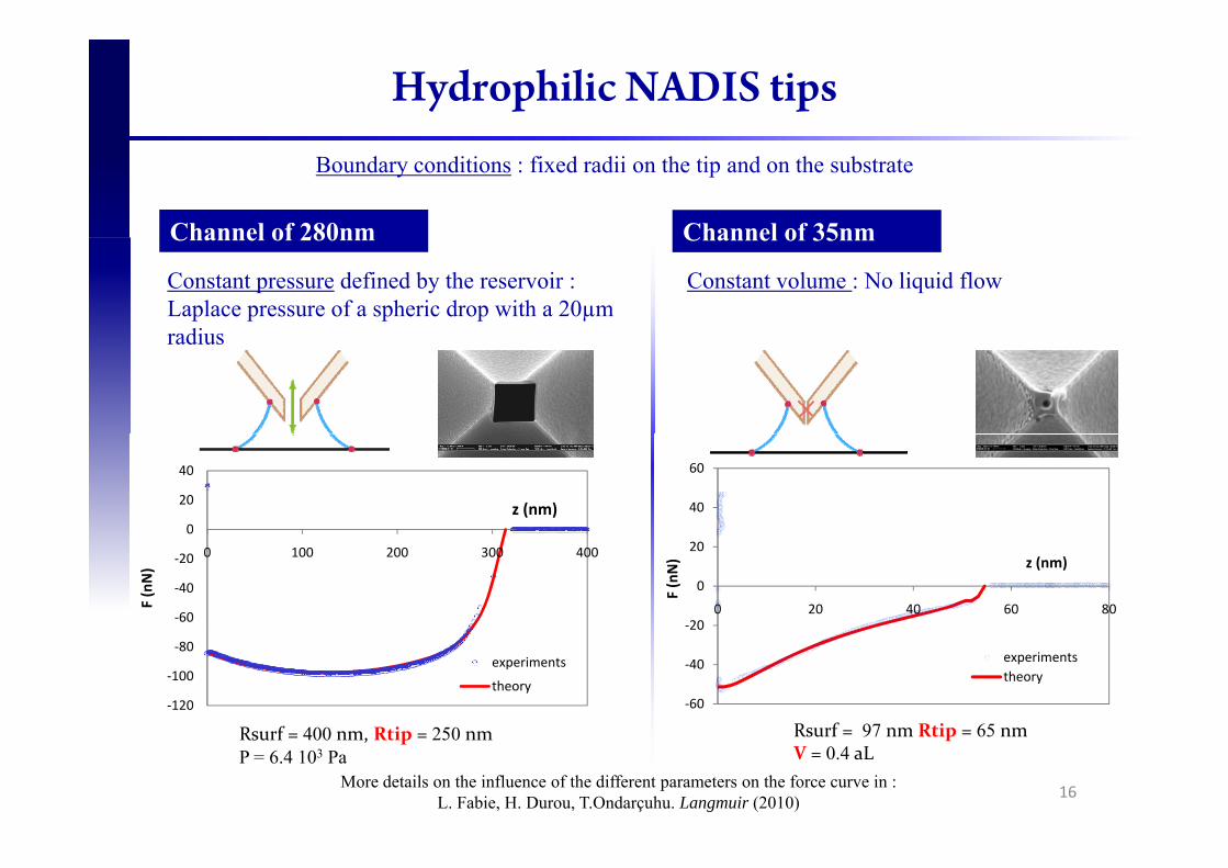
Hydrophilic NADIS tips
Channel of 35nm
Boundary conditions : fixed radii on the tip and on the substrate
Channel of 280nm
Constant pressure defined by the reservoir : Laplace pressure of a spheric drop with a 20µm radius
Channel of 35nmChannel of 280nm
Constant volume : No liquid flow
radius
0
20
40
z (nm) 40
60
‐60
‐40
‐20
0
0 100 200 300 400
F (nN)
‐20
0
20
0 20 40 60 80
F (nN) z (nm)
R f 400 Rti 250‐120
‐100
‐80experiments
theory
Rsurf 97 nm Rtip 65 nm‐60
‐40 experimentstheory
16More details on the influence of the different parameters on the force curve in :
L. Fabie, H. Durou, T.Ondarçuhu. Langmuir (2010)
Rsurf = 400 nm, Rtip = 250 nmP = 6.4 103 Pa
Rsurf = 97 nm Rtip = 65 nmV = 0.4 aL

Lines deposition
NADIS tip is moved at constant velocity while maintaining contact ontop y gthe surface thanks to a nanopositioning table incorporated to the AFM
Phase image for a better contrast
Velocity increasing
17

Spreading dynamics
Channel of 220nmChannel of 500nmChannel of 760nm
Channel of 220nmChannel of 500nmChannel of 760nm
Different from diffusiveDifferent from diffusive law (Dip pen) in t½
J. Jang et al. J. Chem. Phys. (2001)
18
t=w/V

Spreading dynamics
O.V. Voinov, Fluid Dyn. (1976)R G C J Fl id M h (1986)
Cox-Voinov equation : θ 3 − θm3 = 9 ηv
γln L
l⎛ ⎝ ⎜
⎞ ⎠ ⎟
Classical caseR.G. Cox, J. Fluid. Mech. (1986)
Spreading at constant1
θ
Spreading at constantvolume
R ∝ t110
θ ∝1
R 3
NADIS case
R ∝ tL. Tanner, J. Phys. D (1979)
Avec :tanθ ≈ θ ≈
hR − R0
Spreading at constantpressureAvec :
dRh αθ 933
+⎟⎟⎞
⎜⎜⎛
⎟⎞
⎜⎛=
Llnηαh θ
0 p
19
dtRR m αθ 90
+=⎟⎟⎠
⎜⎜⎝ −
⎟⎠
⎜⎝
=l
lnγ
α
R0R

Results of the model
F θ 0 l ti l l tiFor θm= 0, analytical solution : R-R0 = At1/4
F θ ≠ 0 i l l tiFor θm≠ 0, numerical solution
dtdR
RRh
m αθ 933
0
+=⎟⎟⎠
⎞⎜⎜⎝
⎛−
θm=3.5°R0=380nmln(L/l)=10
dtRR 0 ⎠⎝
20
ln(L/l) 10α=238s/muntreated tip: h=56nmHydrophobic tip : h=42.5nm

Results of the model
F θ 0 l ti l l tiFor θm= 0, analytical solution : R-R0 = At1/4
F θ ≠ 0 i l l tiFor θm≠ 0, numerical solution
dtdR
RRh
m αθ 933
0
+=⎟⎟⎠
⎞⎜⎜⎝
⎛−
θm=3.5°R0=380nmln(L/l)=10
dtRR 0 ⎠⎝
21
ln(L/l) 10α=238s/muntreated tip: h=56nmHydrophobic tip : h=42.5nm

Conclusion
Efficient method for nanopatterningEfficient method for nanopatterning
Fundamental studies
Study of the capillary force at the nanoscale
f l f AFM i iuseful for AFM imaging
Spreading dynamics at constant pressure
interesting for printing techniques
22