ncsx magnetic configuration flexibility and...
TRANSCRIPT
NCSX MAGNETIC CONFIGURATION FLEXIBILITYAND ROBUSTNESSN. POMPHREY,a* A. BOOZER,b A. BROOKS,a R. HATCHER,a S. P. HIRSHMAN,c S. HUDSON,a
L. P. KU,a E. A. LAZARUS,c H. MYNICK,a D. MONTICELLO,a M. REDI,a A. REIMAN,a
M. C. ZARNSTORFF,a and I. ZATZa
aPrinceton Plasma Physics Laboratory, Princeton, New Jersey 08540bColumbia University, New York, New York 10027cOak Ridge National Laboratory, Oak Ridge, Tennessee 37831
Received February 17, 2006Accepted for Publication March 30, 2006
The National Compact Stellarator Experiment(NCSX) will study the physics of low–aspect ratio, high-b,quasi-axisymmetric stellarators. To achieve the scien-tific goals of the NCSX mission, the device must be ca-pable of supporting a wide range of variations in plasmaconfiguration about a reference baseline equilibrium. Wedemonstrate the flexibility of NCSX coils to support suchconfiguration variations and demonstrate the robustnessof performance of NCSX plasmas about reference designvalues of the plasma current Ip, b, and profile shapes.The robustness and flexibility calculations make use offree-boundary plasma equilibrium constructions using acombination of nonaxisymmetric modular coils and axi-symmetric toroidal and poloidal field coils. The primarycomputational tool for the studies is STELLOPT, a free-boundary optimization code that varies coil currents totarget configurations with specific physics properties.
KEYWORDS: stellarator, design, flexibility
I. INTRODUCTION
To achieve the scientific goals of the National Com-pact Stellarator Experiment ~NCSX!mission, the NCSXdevice must be capable of supporting a range of varia-tions in plasma configuration about the reference base-line equilibrium. We present a number of numericalcalculations that demonstrate this ability:
1. an investigation of plasma performance as b andIp are varied with fixed profile shape. Stable configura-
tions with low effective helical ripple «h are found over awide region of the Ip-b plane, with a stable path from avacuum state to a full-current high-b configuration withb . 5.0%.
2. an examination of plasma performance whenplasma profiles are varied about reference forms at fixedIp and b. A wide range of configurations is found whoseb limits exceed 3.0% and that have good quasi-axisymmetry, including configurations with finite cur-rent at the plasma edge.
3. an examination of the ability to control the exter-nal transform iext~s! by varying coil currents while con-straining the toroidal field and plasma current to beconstant. Substantial changes in i~s! can be achieved,demonstrating an important control knob for transportand stability experiments on NCSX.
4. a demonstration of the ability to control the de-gree of quasi-axisymmetry while maintaining plasma sta-bility. This provides a means to systematically explorethe role of quasi-axisymmetry in improving the transportproperties of stellarator plasmas.
5. a demonstration of the use of STELLOPT in de-fining experiments that elucidate the role of three-dimensional ~3-D! shape stabilization in setting b limitsseparately for kink and ballooning modes.
Figure 1 shows a top view of the modular coil setM45 used for the flexibility and robustness studies. Thereare six coils in each of the three periods of the machine.Stellarator symmetry implies that within any given pe-riod only three coil currents are independent. The inde-pendent coils are labeled 1, 2, and 3. Stellarator-symmetricpartners are labeled with prime superscripts. The samenumbering convention will be used to identify the coils*E-mail: [email protected]
FUSION SCIENCE AND TECHNOLOGY VOL. 51 FEB. 2007 181

when presenting coil current solutions in our flexibilitystudies.
The three modular coil currents are allowed to varyindependently; thus, the mean ~toroidally averaged! to-roidal magnetic field at a given radius will also vary. Forsystematic experiments it is advantageous to separate theprovision of external transform by 3-D shaping from pro-vision by changes in the average toroidal field ~TF!. Inprinciple, the average toroidal field can be constrained tobe a constant value by varying only two linear combina-tions of the three modular coil currents. However, thisleads to a considerable reduction in flexibility to controlthe external transform. To avoid such a reduction in flex-ibility, NCSX includes an auxiliary TF coil system inwhich the TF coil current is allowed to vary together withthe three modular coil currents in such a way that themean TF field remains constant. The TF coil system iscomposed of 18 coils connected in series, capable ofproviding 60.5 T at radius R � 1.4 m.
A system of six axisymmetric poloidal field ~PF!currents is included for additional flexibility ~see Fig. 2!.Coil PF6 is positioned to give a high-quality dipole ~ver-tical! field in the plasma region. PF5 is positioned so that,in combination with PF6, a high-quality quadrupole fieldis produced. Coils PF4 and PF3 produce, in combinationwith PF5 and PF6, hexapole and octapole fields, respec-tively. Coils PF1 and PF2 are the primary ohmic heating
Fig. 1. Modular coil set M45 used for flexibility and robust-ness studies. Integers 1, 2, and 3 label the three coilswithin each period whose coil currents are allowed tovary independently of one another. Coil k ' is the stel-larator symmetric partner of coil k.
Fig. 2. PF coil geometry. PF3 through PF6 provide additional flexibility for the accomplishment of the physics mission.
Pomphrey et al. NCSX MAGNETIC CONFIGURATION FLEXIBILITY
182 FUSION SCIENCE AND TECHNOLOGY VOL. 51 FEB. 2007

coils and play no role in the flexibility calculations. Table Ishows coil current limits for each of the independent coilsystems. Plasma configurations for all calculations areconstrained to lie within these limits.
The primary computational tool for the flexibilitystudies is STELLOPT ~Ref. 1!, a VMEC-based free-boundary optimizer that varies coil currents to target con-figurations with specific physics properties, such asstability to kink and ballooning modes and good quasi-axisymmetry ~QA!. Essential code modules within STEL-LOPT include an equilibrium solver @VMEC ~Ref. 2!# ,stability analysis codes @TERPSICHORE ~Ref. 3! forkink modes and COBRA ~Ref. 4! for ballooning modes# ,and a QA analyzer. For the calculations presented here,the QA-ness measure targeted in STELLOPT is eitherxBmn
2 � S'Bmn2 0B00
2 , where the Bmn are Fourier compo-nents of the magnetic field analyzed on the s � 0.3, 0.5,and 0.8 magnetic surfaces evaluated in Boozer magneticcoordinates, with the summation taken over modes withn. 0, or «h, the effective helical ripple, calculated by theNEO code module.5 The targeted stability measures arexK
2 � lKn�12 � lKn�0
2 ~the square of the unstable eigen-value of the dominant kink instability for the n � 1
and n � 0 kink families!, and xB2 � SlB
2 ~the sum ofsquares of the maximum ballooning eigenvalue on any ofthe 49 magnetic surfaces used in the VMEC equilibriumcalculation!. All optimized equilibria are constrained tobe tangent at some point to the plasma-facing-componentfirst wall.
A requirement for the design of M45 coils1,6 wasthat the coils should support a free-boundary equilibriumthat reproduces the physics properties of the referenceli383 S3 plasma configuration ~S3 definition: Ip � 174kA, BT � 1.7 T at R � 1.4 m, with bootstrap consistencybetween current and pressure profiles, stable to kinkand ballooning modes at b . 4.2%, and good quasi-axisymmetry with effective helical ripple «h ; 0.5% ats � 0.5!. The reference profiles and reference M45 S3plasma shape are shown in Figs. 3 and 4. Coil currentsthat produce S3 are presented in Table II. A summary ofthe shape and physics parameters for the kink and bal-looning stable reference S3 state is given in Table III.
The S3 configuration defines a single point in theoperating space of NCSX. In the following sections weaddress the following questions on robustness and per-formance: Using the M45 coil set,
TABLE I
Coil Current Limits ~kA-turns! per Coil for Each of the Coil Systems*
M1~kA-turns!
M2~kA-turns!
M3~kA-turns!
TF~kA-turns!
PF3~kA-turns!
PF4~kA-turns!
PF5~kA-turns!
PF6~kA-turns!
864.0 864.0 864.0 6194.0 61739.0 61397.0 6182.0 673.0
*M � modular, TF � toroidal field, PF � poloidal field. Plasma configurations produced in the flexibility studies have coil currentsthat lie within the given limits.
Fig. 3. Baseline reference pressure ~P ! and current ~J{B! profiles as a function of normalized toroidal flux s.
Pomphrey et al. NCSX MAGNETIC CONFIGURATION FLEXIBILITY
FUSION SCIENCE AND TECHNOLOGY VOL. 51 FEB. 2007 183

1. How does the plasma performance change as cur-rents and profiles are changed from the reference?
2. Is the operating space for configurations with ad-equate performance characteristics wide enough to allowfulfillment of the NCSX mission?
II. ROBUSTNESS OF PLASMA PERFORMANCE WITH
RESPECT TO CHANGE IN COIL CURRENT
Whereas in later sections we use STELLOPT to findcoil currents that support configurations with targetedphysics properties, allowing several coil currents to vary,
Fig. 4. Cross sections of plasma shape for reference S3 configurations at bean ~v� 0! and bullet ~v� 0.5! cross sections. Also,rotational transform as a function of normalized toroidal flux s.
TABLE II
Coil Currents for Reference M45 S3 State Using Plasma Profiles Shown in Fig. 2*
M1~kA-turns!
M2~kA-turns!
M3~kA-turns!
TF~kA-turns!
PF3~kA-turns!
PF4~kA-turns!
PF5~kA-turns!
PF6~kA-turns!
694.2 654.6 551.1 27.8 1524.2 1180.0 95.2 �2.3
*Ip � 174 kA, BT � 1.7 T, b� 4.1%. Currents in ohmic coils PF1 and PF2 are zero.
Pomphrey et al. NCSX MAGNETIC CONFIGURATION FLEXIBILITY
184 FUSION SCIENCE AND TECHNOLOGY VOL. 51 FEB. 2007
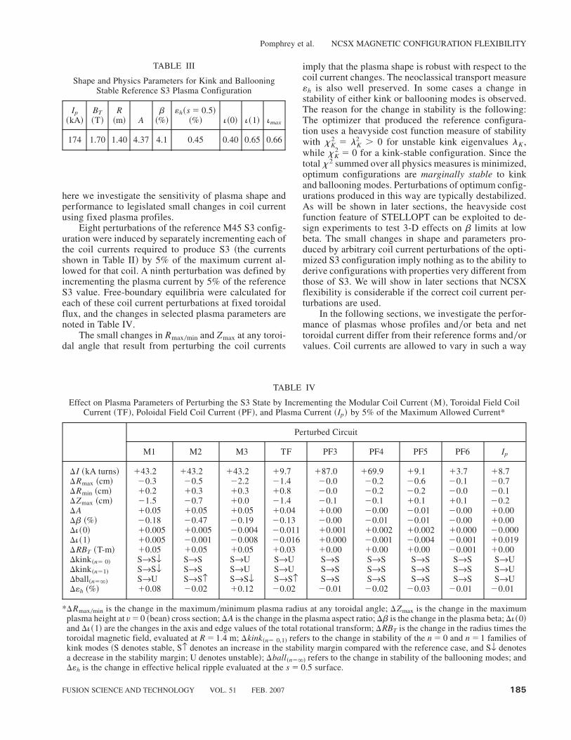
here we investigate the sensitivity of plasma shape andperformance to legislated small changes in coil currentusing fixed plasma profiles.
Eight perturbations of the reference M45 S3 config-uration were induced by separately incrementing each ofthe coil currents required to produce S3 ~the currentsshown in Table II! by 5% of the maximum current al-lowed for that coil. A ninth perturbation was defined byincrementing the plasma current by 5% of the referenceS3 value. Free-boundary equilibria were calculated foreach of these coil current perturbations at fixed toroidalflux, and the changes in selected plasma parameters arenoted in Table IV.
The small changes in Rmax0min and Zmax at any toroi-dal angle that result from perturbing the coil currents
imply that the plasma shape is robust with respect to thecoil current changes. The neoclassical transport measure«h is also well preserved. In some cases a change instability of either kink or ballooning modes is observed.The reason for the change in stability is the following:The optimizer that produced the reference configura-tion uses a heavyside cost function measure of stabilitywith xK
2 � lK2 � 0 for unstable kink eigenvalues lK ,
while xK2 � 0 for a kink-stable configuration. Since the
total x2 summed over all physics measures is minimized,optimum configurations are marginally stable to kinkand ballooning modes. Perturbations of optimum config-urations produced in this way are typically destabilized.As will be shown in later sections, the heavyside costfunction feature of STELLOPT can be exploited to de-sign experiments to test 3-D effects on b limits at lowbeta. The small changes in shape and parameters pro-duced by arbitrary coil current perturbations of the opti-mized S3 configuration imply nothing as to the ability toderive configurations with properties very different fromthose of S3. We will show in later sections that NCSXflexibility is considerable if the correct coil current per-turbations are used.
In the following sections, we investigate the perfor-mance of plasmas whose profiles and0or beta and nettoroidal current differ from their reference forms and0orvalues. Coil currents are allowed to vary in such a way
TABLE III
Shape and Physics Parameters for Kink and BallooningStable Reference S3 Plasma Configuration
Ip
~kA!BT
~T!R~m! A
b~%!
«h~s � 0.5!~%! i~0! i~1! imax
174 1.70 1.40 4.37 4.1 0.45 0.40 0.65 0.66
TABLE IV
Effect on Plasma Parameters of Perturbing the S3 State by Incrementing the Modular Coil Current ~M!, Toroidal Field CoilCurrent ~TF!, Poloidal Field Coil Current ~PF!, and Plasma Current ~Ip! by 5% of the Maximum Allowed Current*
Perturbed Circuit
M1 M2 M3 TF PF3 PF4 PF5 PF6 Ip
DI ~kA turns! �43.2 �43.2 �43.2 �9.7 �87.0 �69.9 �9.1 �3.7 �8.7DRmax ~cm! �0.3 �0.5 �2.2 �1.4 �0.0 �0.2 �0.6 �0.1 �0.7DRmin ~cm! �0.2 �0.3 �0.3 �0.8 �0.0 �0.2 �0.2 �0.0 �0.1DZmax ~cm! �1.5 �0.7 �0.0 �1.4 �0.1 �0.1 �0.1 �0.1 �0.2DA �0.05 �0.05 �0.05 �0.04 �0.00 �0.00 �0.01 �0.00 �0.00Db ~%! �0.18 �0.47 �0.19 �0.13 �0.00 �0.01 �0.01 �0.00 �0.00Di~0! �0.005 �0.005 �0.004 �0.011 �0.001 �0.002 �0.002 �0.000 �0.000Di~1! �0.005 �0.001 �0.008 �0.016 �0.000 �0.001 �0.004 �0.001 �0.019DRBT ~T-m! �0.05 �0.05 �0.05 �0.03 �0.00 �0.00 �0.00 �0.001 �0.00Dkink~n� 0! SrSf SrS SrU SrU SrS SrS SrS SrS SrUDkink~n�1! SrSf SrS SrU SrU SrS SrS SrS SrS SrUDball~n�`! SrU SrSF SrSf SrSF SrS SrS SrS SrS SrUD«h ~%! �0.08 �0.02 �0.12 �0.02 �0.01 �0.02 �0.03 �0.01 �0.01
*DRmax0min is the change in the maximum0minimum plasma radius at any toroidal angle; DZmax is the change in the maximumplasma height at v� 0 ~bean! cross section; DA is the change in the plasma aspect ratio; Db is the change in the plasma beta; Di~0!and Di~1! are the changes in the axis and edge values of the total rotational transform; DRBT is the change in the radius times thetoroidal magnetic field, evaluated at R � 1.4 m; Dkink~n� 0,1! refers to the change in stability of the n � 0 and n � 1 families ofkink modes ~S denotes stable, SF denotes an increase in the stability margin compared with the reference case, and Sf denotesa decrease in the stability margin; U denotes unstable!; Dball~n�`! refers to the change in stability of the ballooning modes; andD«h is the change in effective helical ripple evaluated at the s � 0.5 surface.
Pomphrey et al. NCSX MAGNETIC CONFIGURATION FLEXIBILITY
FUSION SCIENCE AND TECHNOLOGY VOL. 51 FEB. 2007 185
that xBmn2 ~n � 0! is minimized while kink and ballooning
stability are enforced. Plasmas are constrained to be lim-ited by the first-wall boundary. We show that stable plas-mas with good quasi-axisymmetry can be obtained for awide range of assumed plasma conditions.
III. ROBUSTNESS OF PERFORMANCE AS b AND IpARE VARIED
In Ref. 7, discharge simulations are presented as asequence of free-boundary equilibria corresponding tothe “evolution” of an NCSX plasma from a particular S1state where b� 0.0% to a final S3 state where b . 4%.Pressure profile evolution is consistent with a one-
dimensional transport model. The evolution from initialto final states can be represented as a curve on an Ip-bplane. Each point on the curve is associated with a par-ticular profile of plasma current and pressure.
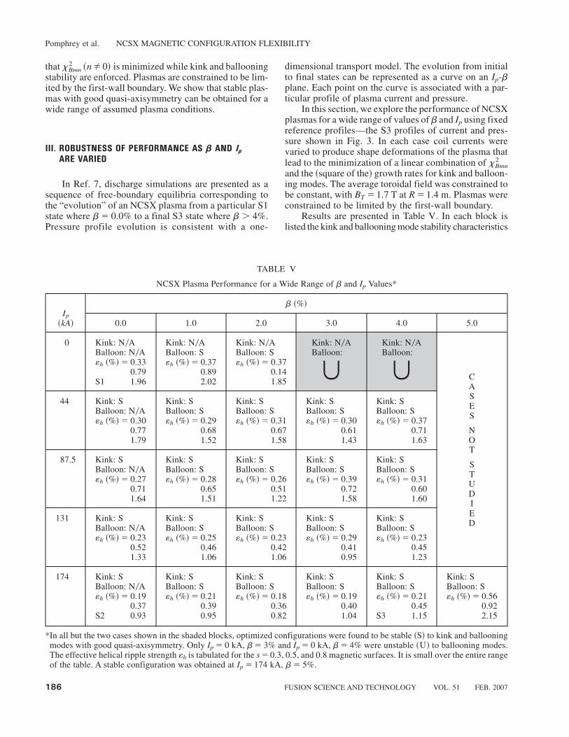
In this section, we explore the performance of NCSXplasmas for a wide range of values of b and Ip using fixedreference profiles—the S3 profiles of current and pres-sure shown in Fig. 3. In each case coil currents werevaried to produce shape deformations of the plasma thatlead to the minimization of a linear combination of xBmn
2
and the ~square of the! growth rates for kink and balloon-ing modes. The average toroidal field was constrained tobe constant, with BT � 1.7 T at R � 1.4 m. Plasmas wereconstrained to be limited by the first-wall boundary.
Results are presented in Table V. In each block islisted the kink and ballooning mode stability characteristics
TABLE V
NCSX Plasma Performance for a Wide Range of b and Ip Values*
b ~%!Ip
~kA! 0.0 1.0 2.0 3.0 4.0 5.0
0 Kink: N0ABalloon: N0A«h ~%!� 0.33
0.79S1 1.96
Kink: N0ABalloon: S«h ~%!� 0.37
0.892.02
Kink: N0ABalloon: S«h ~%!� 0.37
0.141.85
Kink: N0ABalloon:
�Kink: N0ABalloon:
� CASES
NOT
STUDIED
44 Kink: SBalloon: N0A«h ~%!� 0.30
0.771.79
Kink: SBalloon: S«h ~%!� 0.29
0.681.52
Kink: SBalloon: S«h ~%!� 0.31
0.671.58
Kink: SBalloon: S«h ~%!� 0.30
0.611.43
Kink: SBalloon: S«h ~%!� 0.37
0.711.63
87.5 Kink: SBalloon: N0A«h ~%!� 0.27
0.711.64
Kink: SBalloon: S«h ~%!� 0.28
0.651.51
Kink: SBalloon: S«h ~%!� 0.26
0.511.22
Kink: SBalloon: S«h ~%!� 0.39
0.721.58
Kink: SBalloon: S«h ~%!� 0.31
0.601.60
131 Kink: SBalloon: N0A«h ~%!� 0.23
0.521.33
Kink: SBalloon: S«h ~%!� 0.25
0.461.06
Kink: SBalloon: S«h ~%!� 0.23
0.421.06
Kink: SBalloon: S«h ~%!� 0.29
0.410.95
Kink: SBalloon: S«h ~%!� 0.23
0.451.23
174 Kink: SBalloon: N0A«h ~%!� 0.19
0.37S2 0.93
Kink: SBalloon: S«h ~%!� 0.21
0.390.95
Kink: SBalloon: S«h ~%!� 0.18
0.360.82
Kink: SBalloon: S«h ~%!� 0.19
0.401.04
Kink: SBalloon: S«h ~%!� 0.21
0.45S3 1.15
Kink: SBalloon: S«h ~%!� 0.56
0.922.15
*In all but the two cases shown in the shaded blocks, optimized configurations were found to be stable ~S! to kink and ballooningmodes with good quasi-axisymmetry. Only Ip � 0 kA, b� 3% and Ip � 0 kA, b� 4% were unstable ~U! to ballooning modes.The effective helical ripple strength «h is tabulated for the s � 0.3, 0.5, and 0.8 magnetic surfaces. It is small over the entire rangeof the table. A stable configuration was obtained at Ip � 174 kA, b� 5%.
Pomphrey et al. NCSX MAGNETIC CONFIGURATION FLEXIBILITY
186 FUSION SCIENCE AND TECHNOLOGY VOL. 51 FEB. 2007

of the optimized configuration, as well as the effectivehelical ripple strength «h ~%!, evaluated on the s � 0.3,0.5, and 0.8 magnetic surfaces. Stable free-boundary equi-libria were found for nearly every case in the calculatedIp-b plane.All equilibria were stable to kink modes; nearlyall equilibria were stable to ballooning modes. For Ip �174 kA the free-boundary equilibrium with b � 5.0%was stable to both ballooning and kink modes. This bvalue is substantially higher than the reference li383 fixed-boundary b limit. @A full exploration of the maximum blimit using the M45 coils has not yet been made; how-ever, a kink-stable configuration was found with b �6.0% and «h � 0.8% at s � 0.5 using the standard ~un-optimized! S3 profiles. Ballooning modes for this b �6% configuration were unstable on only two adjacentmagnetic surfaces near the edge of the plasma.# Twocases in Table V were unstable to ballooning modes.These cases ~shaded boxes! are Ip � 0 kA, b� 3.0% andIp � 0 kA, b� 4.0%. With regard to QA-ness, «h, 0.5%at s�0.5, typically, and «h never exceeds 1.0% at s�0.5.As discussed in Ref. 8, it is expected that for this mag-nitude of ripple amplitude, and with standard conditionsof plasma temperature and density, the helical ripple trans-port will be small compared with axisymmetric neoclas-sical transport.
Using reference profiles, we conclude there is a sub-stantial region of stability with good QA-ness in the Ip-bplane.
The maximum difference between the coil currentsfor any equilibrium state in the Ip-b scan of Table V andthe reference M45 S3 state is presented in Table VI. Forthe modular coil currents the variation is less than 10%from the nominal S3 currents ~Table II!. The variation inpoloidal field coil current is;100%. Plots of coil currentversus beta, as a fraction of allowed current, are shown inFig. 5 for the diagonal sequence Ip @ b connecting thevacuum state, S1, and the reference full-current, high-beta state, S3. Coil currents for this sequence, as well asfor all cases shown in Table V, are within the allowablesrange.
An overlay of plasma boundaries and calculated iotaprofiles for a subset of stable equilibria from the Ip-bscan are presented in Fig. 6. A wide range of plasma
boundary shapes and iota profiles is seen, including asubstantial variation in magnetic shear, di0ds. These datashow the possibility of designing experiments to inves-tigate shear stabilization of neoclassical tearing modes.Later, in Sec. VI, we show how the ability to control i~s!at fixed Ip and b using the external magnetic fields allowsthe design of experiments to investigate 3-D shape sta-bilization of external kink modes.
IV. ROBUSTNESS OF PERFORMANCE AS PLASMA
PROFILES ARE VARIED
For the results presented so far, the current and pres-sure profiles have had the same form as the referenceli383 profiles. Now we investigate the effect on plasmaperformance of choosing plasma profiles that are differ-ent from the reference profiles. First, we examine theperformance of plasmas supported by NCSX coils for arange of current profiles, fixing the pressure profile equalto the reference form shown in Fig. 3. The effect of vary-ing the current profile in the core region of the plasma isconsidered separately from its effect in the edge region.In another set of experiments, the effect of varying thepressure profile is considered, with the current profileheld fixed equal to its reference form, also shown inFig. 3. We show that good plasma performance is ob-tained for a wide range of current and pressure profiles.The results allay concern that the optimization methodsused for designing the plasma configuration and coil sys-tem may have produced only a narrow operating space ofgood performance plasmas.
IV.A. Variation of the Current Profile in the Core Region
Here we examine the performance of plasmas sup-ported by NCSX coils for current profiles that differfrom the reference form mainly in the core region. Aone-parameter family of current profiles Ja is conve-niently defined by
Ja~s! � ~1 � a!J ref~s!� aJ peaked~s! , ~1!
TABLE VI
Coil Current Variation for the Ip-b Scan Results*
DIM1~kA-turns!
DIM2~kA-turns!
DIM3~kA-turns!
DITF~kA-turns!
DIPF3~kA-turns!
DIPF4~kA-turns!
DIPF5~kA-turns!
DIPF6~kA-turns!
�52 �41 �46 �31 �0 �0 �78 �28�38 �12 �27 �46 �1691 �1627 �222 �36
*In each column is shown the maximum �0� variation in the current for coil k compared with the current required to support theS3 state.
Pomphrey et al. NCSX MAGNETIC CONFIGURATION FLEXIBILITY
FUSION SCIENCE AND TECHNOLOGY VOL. 51 FEB. 2007 187
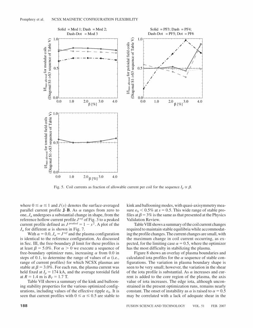
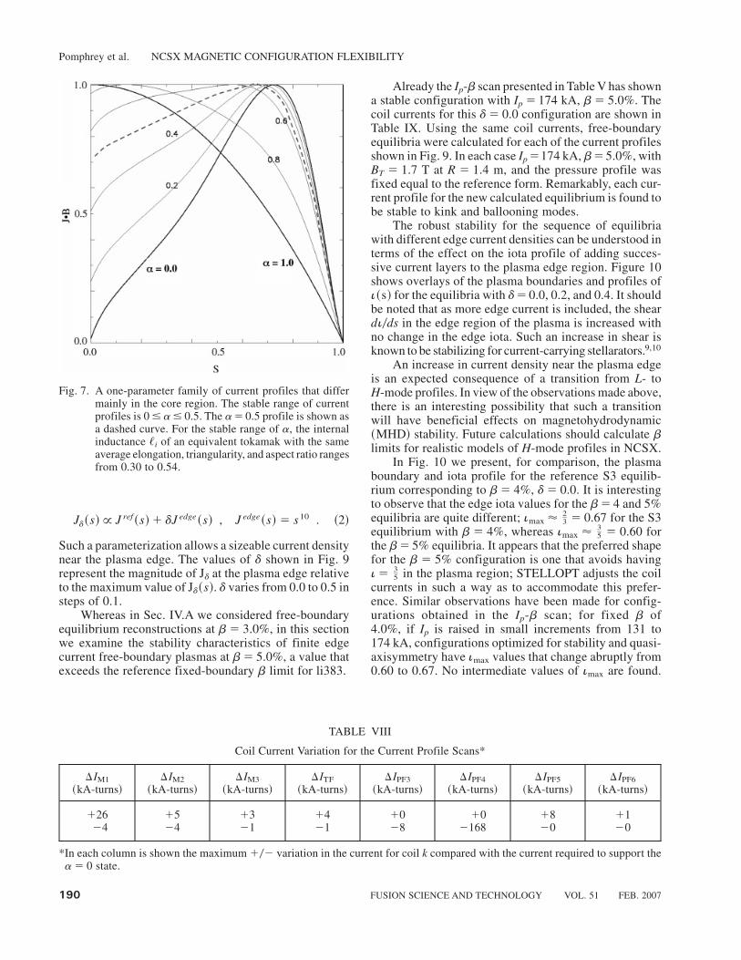
where 0 � a� 1 and J ~s! denotes the surface-averagedparallel current profile J{B. As a ranges from zero toone, Ja undergoes a substantial change in shape, from thereference hollow current profile J ref of Fig. 3 to a peakedcurrent profile defined as J peaked � 1 � s 2. A plot of theJa for different a is shown in Fig. 7.
With a� 0.0, Ja� J ref and the plasma configurationis identical to the reference configuration. As discussedin Sec. III, the free-boundary b limit for these profiles isat least b� 5.0%. For a . 0 we execute a sequence offree-boundary optimizer runs, increasing a from 0.0 insteps of 0.1, to determine the range of values of a ~i.e.,range of current profiles! for which NCSX plasmas arestable at b� 3.0%. For each run, the plasma current washeld fixed at Ip � 174 kA, and the average toroidal fieldat R � 1.4 m is BT � 1.7 T.
Table VII shows a summary of the kink and balloon-ing stability properties for the various optimized config-urations, including values of the effective ripple «h. It isseen that current profiles with 0 � a � 0.5 are stable to
kink and ballooning modes, with quasi-axisymmetry mea-sure «h, 0.5% at s � 0.5. This wide range of stable pro-files at b�3% is the same as that presented at the PhysicsValidation Review.
TableVIII shows a summary of the coil current changesrequired to maintain stable equilibria while accommodat-ing the profile changes. The current changes are small, withthe maximum change in coil current occurring, as ex-pected, for the limiting case a� 0.5, where the optimizerhas the most difficulty in stabilizing the plasma.
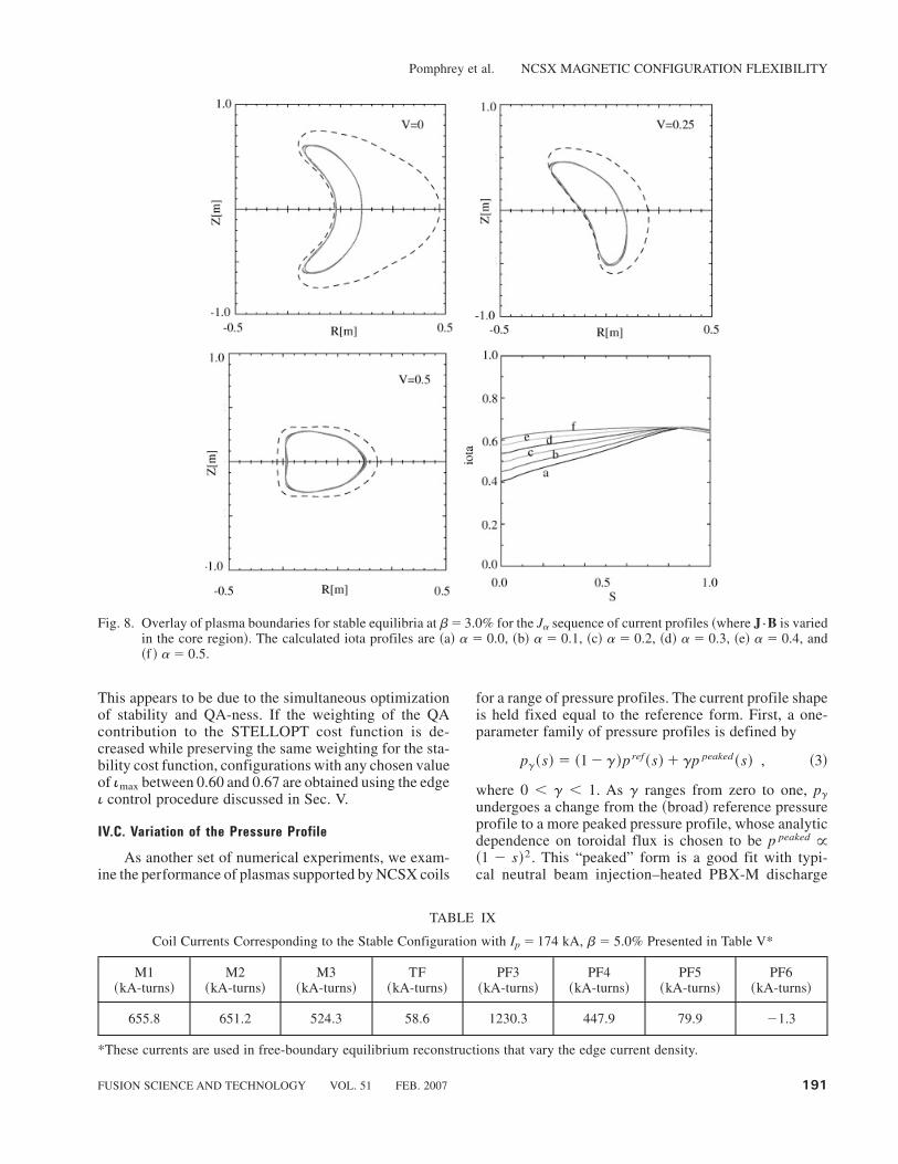
Figure 8 shows an overlay of plasma boundaries andcalculated iota profiles for the a sequence of stable con-figurations. The variation in plasma boundary shape isseen to be very small; however, the variation in the shearof the iota profile is substantial. As a increases and cur-rent is added to the core region of the plasma, the axisvalue of iota increases. The edge iota, although uncon-strained in the present optimization runs, remains nearlyconstant. The onset of instability as a is raised to a� 0.5may be correlated with a lack of adequate shear in the
Fig. 5. Coil currents as fraction of allowable current per coil for the sequence Ip @ b.
Pomphrey et al. NCSX MAGNETIC CONFIGURATION FLEXIBILITY
188 FUSION SCIENCE AND TECHNOLOGY VOL. 51 FEB. 2007

iota profile. On the other hand, we see from the i~s! plotsof the Ip � 174 kA, b� 0, 2, and 4% sequence of mar-ginally stable equilibria shown in Fig. 6 that such anassumption may be presumptive. Further study is neededto confirm such a conclusion.
IV.B. Variation of the Current Profile in the Edge Region
We now explore the effect of varying the currentprofile in the edge region. In particular, we consider thefamily of current profiles Jd, shown in Fig. 9, where
Fig. 6. Overlay of plasma boundaries and calculated iota profiles for various optimized equilibria from the Ip-b scan ~Table V!.The calculated iota profiles are ~a! Ip � 0 kA, b� 0%, ~b! Ip � 0 kA, b� 2%, ~c! Ip � 87.5 kA, b� 0%, ~d! Ip � 87.5 kA,b� 2%, ~e! Ip � 87.5 kA, b� 4%, ~f ! Ip �174 kA, b� 0%, ~g! Ip �174 kA, b� 2%, and ~h! Ip �174 kA, b� 4%. Notethe wide range of iota profiles ~shear and edge iota values! for which plasmas were found to be stable.
TABLE VII
Stability Properties and Effective Helical Ripple «h at s � 0.3, 0.5, and 0.8 for Current Profiles Parameterizedby Peakedness Parameter a @see Eq. ~1! and Fig. 7#*
a
0.0 0.1 0.2 0.3 0.4 0.5 0.6
Kink: SBalloon: S«h ~%!� 0.19
0.401.04
Kink: SBalloon: S«h ~%!� 0.18
0.401.12
Kink: SBalloon: S«h ~%!� 0.18
0.421.25
Kink: SBalloon: S«h ~%!� 0.19
0.451.36
Kink: SBalloon: S«h ~%!� 0.20
0.491.42
Kink: SBalloon: S«h ~%!� 0.21
0.491.38
Kink:
�*All equilibria correspond to Ip � 174 kA, b� 3.0%, with BT � 1.7 T at R � 1.4 m. The stable range of a is 0 � a � 0.5.
Pomphrey et al. NCSX MAGNETIC CONFIGURATION FLEXIBILITY
FUSION SCIENCE AND TECHNOLOGY VOL. 51 FEB. 2007 189
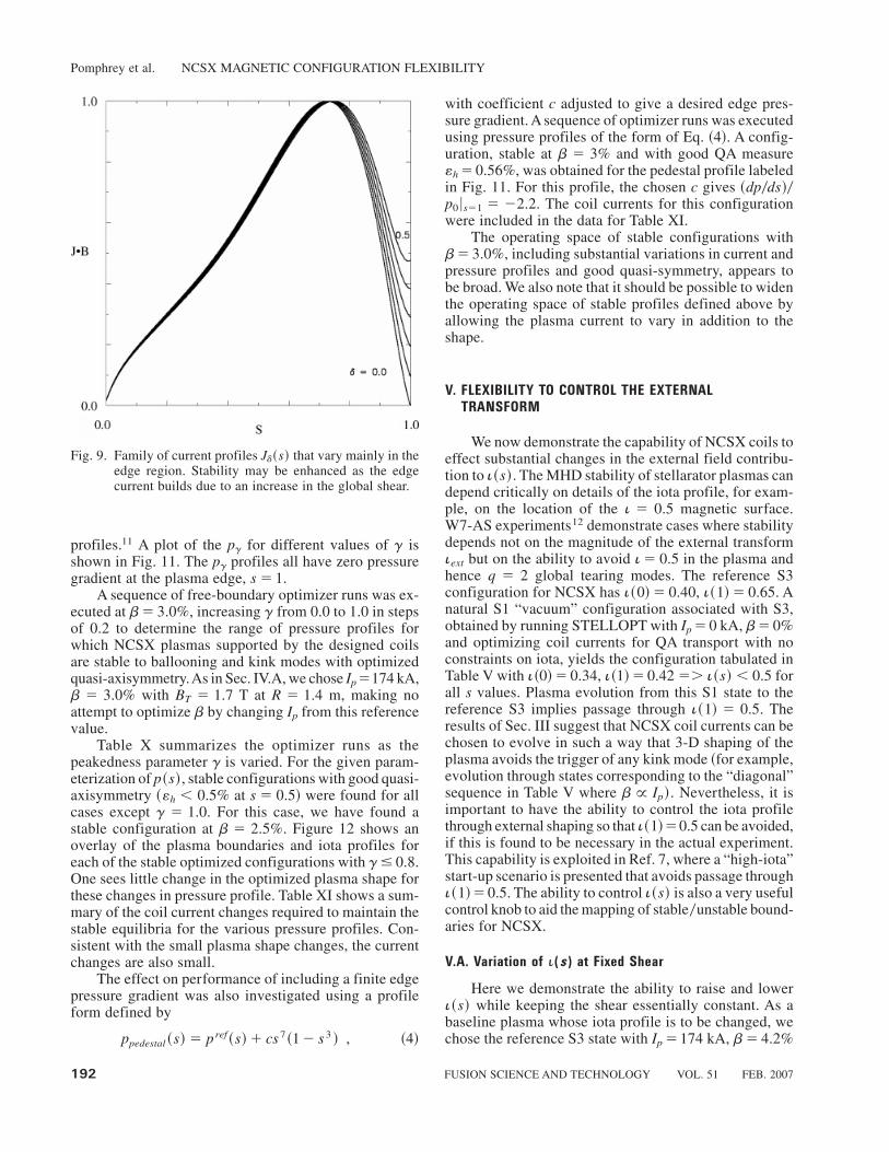
Jd~s! @ J ref~s!� dJ edge~s! , J edge~s! � s 10 . ~2!
Such a parameterization allows a sizeable current densitynear the plasma edge. The values of d shown in Fig. 9represent the magnitude of Jd at the plasma edge relativeto the maximum value of Jd~s!. d varies from 0.0 to 0.5 insteps of 0.1.
Whereas in Sec. IV.A we considered free-boundaryequilibrium reconstructions at b� 3.0%, in this sectionwe examine the stability characteristics of finite edgecurrent free-boundary plasmas at b� 5.0%, a value thatexceeds the reference fixed-boundary b limit for li383.
Already the Ip-b scan presented in Table V has showna stable configuration with Ip � 174 kA, b� 5.0%. Thecoil currents for this d� 0.0 configuration are shown inTable IX. Using the same coil currents, free-boundaryequilibria were calculated for each of the current profilesshown in Fig. 9. In each case Ip �174 kA, b� 5.0%, withBT � 1.7 T at R � 1.4 m, and the pressure profile wasfixed equal to the reference form. Remarkably, each cur-rent profile for the new calculated equilibrium is found tobe stable to kink and ballooning modes.
The robust stability for the sequence of equilibriawith different edge current densities can be understood interms of the effect on the iota profile of adding succes-sive current layers to the plasma edge region. Figure 10shows overlays of the plasma boundaries and profiles ofi~s! for the equilibria with d� 0.0, 0.2, and 0.4. It shouldbe noted that as more edge current is included, the sheardi0ds in the edge region of the plasma is increased withno change in the edge iota. Such an increase in shear isknown to be stabilizing for current-carrying stellarators.9,10
An increase in current density near the plasma edgeis an expected consequence of a transition from L- toH-mode profiles. In view of the observations made above,there is an interesting possibility that such a transitionwill have beneficial effects on magnetohydrodynamic~MHD! stability. Future calculations should calculate blimits for realistic models of H-mode profiles in NCSX.
In Fig. 10 we present, for comparison, the plasmaboundary and iota profile for the reference S3 equilib-rium corresponding to b� 4%, d� 0.0. It is interestingto observe that the edge iota values for the b� 4 and 5%equilibria are quite different; imax'
23_ � 0.67 for the S3
equilibrium with b � 4%, whereas imax '35_ � 0.60 for
the b� 5% equilibria. It appears that the preferred shapefor the b � 5% configuration is one that avoids havingi� 3
5_ in the plasma region; STELLOPT adjusts the coil
currents in such a way as to accommodate this prefer-ence. Similar observations have been made for config-urations obtained in the Ip-b scan; for fixed b of4.0%, if Ip is raised in small increments from 131 to174 kA, configurations optimized for stability and quasi-axisymmetry have imax values that change abruptly from0.60 to 0.67. No intermediate values of imax are found.
Fig. 7. A one-parameter family of current profiles that differmainly in the core region. The stable range of currentprofiles is 0 � a� 0.5. The a� 0.5 profile is shown asa dashed curve. For the stable range of a, the internalinductance �i of an equivalent tokamak with the sameaverage elongation, triangularity, and aspect ratio rangesfrom 0.30 to 0.54.
TABLE VIII
Coil Current Variation for the Current Profile Scans*
DIM1~kA-turns!
DIM2~kA-turns!
DIM3~kA-turns!
DITF~kA-turns!
DIPF3~kA-turns!
DIPF4~kA-turns!
DIPF5~kA-turns!
DIPF6~kA-turns!
�26 �5 �3 �4 �0 �0 �8 �1�4 �4 �1 �1 �8 �168 �0 �0
*In each column is shown the maximum �0� variation in the current for coil k compared with the current required to support thea� 0 state.
Pomphrey et al. NCSX MAGNETIC CONFIGURATION FLEXIBILITY
190 FUSION SCIENCE AND TECHNOLOGY VOL. 51 FEB. 2007
This appears to be due to the simultaneous optimizationof stability and QA-ness. If the weighting of the QAcontribution to the STELLOPT cost function is de-creased while preserving the same weighting for the sta-bility cost function, configurations with any chosen valueof imax between 0.60 and 0.67 are obtained using the edgei control procedure discussed in Sec. V.
IV.C. Variation of the Pressure Profile
As another set of numerical experiments, we exam-ine the performance of plasmas supported by NCSX coils
for a range of pressure profiles. The current profile shapeis held fixed equal to the reference form. First, a one-parameter family of pressure profiles is defined by
pg~s! � ~1 � g!pref~s!� gp peaked~s! , ~3!
where 0 , g , 1. As g ranges from zero to one, pgundergoes a change from the ~broad! reference pressureprofile to a more peaked pressure profile, whose analyticdependence on toroidal flux is chosen to be p peaked @~1 � s!2. This “peaked” form is a good fit with typi-cal neutral beam injection–heated PBX-M discharge
Fig. 8. Overlay of plasma boundaries for stable equilibria at b� 3.0% for the Ja sequence of current profiles ~where J{B is variedin the core region!. The calculated iota profiles are ~a! a � 0.0, ~b! a � 0.1, ~c! a � 0.2, ~d! a � 0.3, ~e! a � 0.4, and~f ! a� 0.5.
TABLE IX
Coil Currents Corresponding to the Stable Configuration with Ip � 174 kA, b� 5.0% Presented in Table V*
M1~kA-turns!
M2~kA-turns!
M3~kA-turns!
TF~kA-turns!
PF3~kA-turns!
PF4~kA-turns!
PF5~kA-turns!
PF6~kA-turns!
655.8 651.2 524.3 58.6 1230.3 447.9 79.9 �1.3
*These currents are used in free-boundary equilibrium reconstructions that vary the edge current density.
Pomphrey et al. NCSX MAGNETIC CONFIGURATION FLEXIBILITY
FUSION SCIENCE AND TECHNOLOGY VOL. 51 FEB. 2007 191
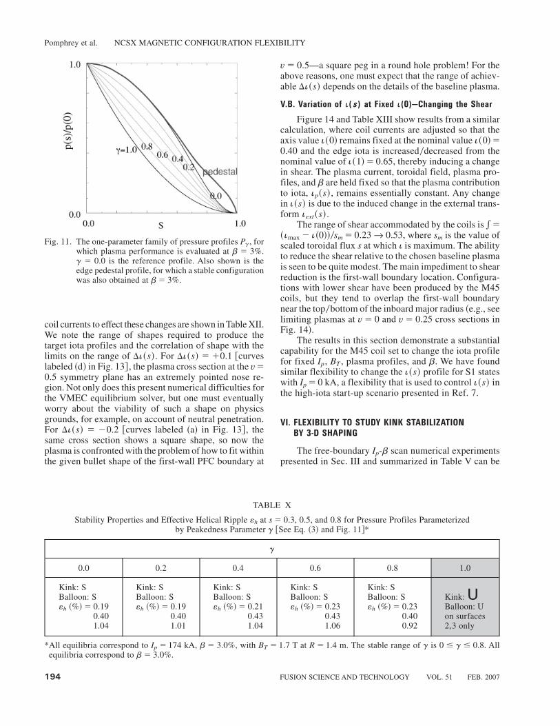
profiles.11 A plot of the pg for different values of g isshown in Fig. 11. The pg profiles all have zero pressuregradient at the plasma edge, s � 1.
A sequence of free-boundary optimizer runs was ex-ecuted at b� 3.0%, increasing g from 0.0 to 1.0 in stepsof 0.2 to determine the range of pressure profiles forwhich NCSX plasmas supported by the designed coilsare stable to ballooning and kink modes with optimizedquasi-axisymmetry.As in Sec. IV.A, we chose Ip�174 kA,b � 3.0% with BT � 1.7 T at R � 1.4 m, making noattempt to optimize b by changing Ip from this referencevalue.
Table X summarizes the optimizer runs as thepeakedness parameter g is varied. For the given param-eterization of p~s!, stable configurations with good quasi-axisymmetry ~«h , 0.5% at s � 0.5! were found for allcases except g � 1.0. For this case, we have found astable configuration at b � 2.5%. Figure 12 shows anoverlay of the plasma boundaries and iota profiles foreach of the stable optimized configurations with g� 0.8.One sees little change in the optimized plasma shape forthese changes in pressure profile. Table XI shows a sum-mary of the coil current changes required to maintain thestable equilibria for the various pressure profiles. Con-sistent with the small plasma shape changes, the currentchanges are also small.
The effect on performance of including a finite edgepressure gradient was also investigated using a profileform defined by
ppedestal ~s! � pref~s!� cs 7~1 � s 3 ! , ~4!
with coefficient c adjusted to give a desired edge pres-sure gradient. A sequence of optimizer runs was executedusing pressure profiles of the form of Eq. ~4!. A config-uration, stable at b � 3% and with good QA measure«h � 0.56%, was obtained for the pedestal profile labeledin Fig. 11. For this profile, the chosen c gives ~dp0ds!0p06s�1 � �2.2. The coil currents for this configurationwere included in the data for Table XI.
The operating space of stable configurations withb� 3.0%, including substantial variations in current andpressure profiles and good quasi-symmetry, appears tobe broad. We also note that it should be possible to widenthe operating space of stable profiles defined above byallowing the plasma current to vary in addition to theshape.
V. FLEXIBILITY TO CONTROL THE EXTERNAL
TRANSFORM
We now demonstrate the capability of NCSX coils toeffect substantial changes in the external field contribu-tion to i~s!. The MHD stability of stellarator plasmas candepend critically on details of the iota profile, for exam-ple, on the location of the i � 0.5 magnetic surface.W7-AS experiments12 demonstrate cases where stabilitydepends not on the magnitude of the external transformiext but on the ability to avoid i� 0.5 in the plasma andhence q � 2 global tearing modes. The reference S3configuration for NCSX has i~0!� 0.40, i~1!� 0.65. Anatural S1 “vacuum” configuration associated with S3,obtained by running STELLOPT with Ip � 0 kA, b� 0%and optimizing coil currents for QA transport with noconstraints on iota, yields the configuration tabulated inTable V with i~0!� 0.34, i~1!� 0.42 �� i~s! , 0.5 forall s values. Plasma evolution from this S1 state to thereference S3 implies passage through i~1! � 0.5. Theresults of Sec. III suggest that NCSX coil currents can bechosen to evolve in such a way that 3-D shaping of theplasma avoids the trigger of any kink mode ~for example,evolution through states corresponding to the “diagonal”sequence in Table V where b @ Ip!. Nevertheless, it isimportant to have the ability to control the iota profilethrough external shaping so that i~1!�0.5 can be avoided,if this is found to be necessary in the actual experiment.This capability is exploited in Ref. 7, where a “high-iota”start-up scenario is presented that avoids passage throughi~1!� 0.5. The ability to control i~s! is also a very usefulcontrol knob to aid the mapping of stable0unstable bound-aries for NCSX.
V.A. Variation of �(s) at Fixed Shear
Here we demonstrate the ability to raise and loweri~s! while keeping the shear essentially constant. As abaseline plasma whose iota profile is to be changed, wechose the reference S3 state with Ip �174 kA, b� 4.2%
Fig. 9. Family of current profiles Jd~s! that vary mainly in theedge region. Stability may be enhanced as the edgecurrent builds due to an increase in the global shear.
Pomphrey et al. NCSX MAGNETIC CONFIGURATION FLEXIBILITY
192 FUSION SCIENCE AND TECHNOLOGY VOL. 51 FEB. 2007

and axis and edge iota values of i~0!� 0.40 and i~1!�0.65, respectively. The choice of baseline plasma for theiota flexibility experiments is arbitrary, since in an actualexperiment we may be interested in exploring the effectsof changing the iota profile for a variety of plasma states.For the iota scan experiments we target desired changesin i~0! and i~1! relative to the baseline values and opti-mize xBmn
2 , making no attempt to stabilize the kink andballooning modes; the goal here is to explore coil flexi-bility, not plasma performance. The plasma current is
held fixed at Ip �174 kA, and the toroidally averaged BT
is held constant at 1.7 T at R �1.4 m. We seek to changei~s! at fixed plasma current and toroidal field by 3-Dshaping only. All configurations are further constrainedby the first-wall poloidal field coil ~PFC! boundary.
Figure 13 shows plasma boundaries and calculatediota profiles for cases where i~0! and i~1! were pro-grammed to change by equal amounts so as to keep theshear constant. Substantial changesDi~s!� @�0.2, �0.1#relative to the baseline are shown possible. The required
Fig. 10. Overlay of three plasma boundaries for stable equilibria at b� 5% with varying edge current densities ~d� 0.0, 0.2, and0.4!. The coil currents are the same in all cases. The plasma boundaries vary little, but there is seen to be a difference withthe plasma boundary for the reference S3 state with b � 4%. Also shown are the i~s! profiles ~shown plotted in twoframes, the second of which is a magnification of the first!, from which the increase in edge shear is evident: ~a! b� 4%,d� 0.0 ~S3 state!, ~b! b� 5%, d� 0.0, ~c! b� 5%, d� 0.2, and ~d! b� 5%, d� 0.4.
Pomphrey et al. NCSX MAGNETIC CONFIGURATION FLEXIBILITY
FUSION SCIENCE AND TECHNOLOGY VOL. 51 FEB. 2007 193
coil currents to effect these changes are shown in Table XII.We note the range of shapes required to produce thetarget iota profiles and the correlation of shape with thelimits on the range of Di~s!. For Di~s! � �0.1 @curveslabeled ~d! in Fig. 13# , the plasma cross section at the v�0.5 symmetry plane has an extremely pointed nose re-gion. Not only does this present numerical difficulties forthe VMEC equilibrium solver, but one must eventuallyworry about the viability of such a shape on physicsgrounds, for example, on account of neutral penetration.For Di~s! � �0.2 @curves labeled ~a! in Fig. 13# , thesame cross section shows a square shape, so now theplasma is confronted with the problem of how to fit withinthe given bullet shape of the first-wall PFC boundary at
v� 0.5—a square peg in a round hole problem! For theabove reasons, one must expect that the range of achiev-able Di~s! depends on the details of the baseline plasma.
V.B. Variation of �(s) at Fixed �(0)—Changing the Shear
Figure 14 and Table XIII show results from a similarcalculation, where coil currents are adjusted so that theaxis value i~0! remains fixed at the nominal value i~0!�0.40 and the edge iota is increased0decreased from thenominal value of i~1!� 0.65, thereby inducing a changein shear. The plasma current, toroidal field, plasma pro-files, and b are held fixed so that the plasma contributionto iota, ip~s!, remains essentially constant. Any changein i~s! is due to the induced change in the external trans-form iext~s!.
The range of shear accommodated by the coils is *�~imax � i~0!!0sm � 0.23r 0.53, where sm is the value ofscaled toroidal flux s at which i is maximum. The abilityto reduce the shear relative to the chosen baseline plasmais seen to be quite modest. The main impediment to shearreduction is the first-wall boundary location. Configura-tions with lower shear have been produced by the M45coils, but they tend to overlap the first-wall boundarynear the top0bottom of the inboard major radius ~e.g., seelimiting plasmas at v� 0 and v� 0.25 cross sections inFig. 14!.
The results in this section demonstrate a substantialcapability for the M45 coil set to change the iota profilefor fixed Ip, BT , plasma profiles, and b. We have foundsimilar flexibility to change the i~s! profile for S1 stateswith Ip � 0 kA, a flexibility that is used to control i~s! inthe high-iota start-up scenario presented in Ref. 7.
VI. FLEXIBILITY TO STUDY KINK STABILIZATION
BY 3-D SHAPING
The free-boundary Ip-b scan numerical experimentspresented in Sec. III and summarized in Table V can be
Fig. 11. The one-parameter family of pressure profiles Pg, forwhich plasma performance is evaluated at b � 3%.g � 0.0 is the reference profile. Also shown is theedge pedestal profile, for which a stable configurationwas also obtained at b� 3%.
TABLE X
Stability Properties and Effective Helical Ripple «h at s � 0.3, 0.5, and 0.8 for Pressure Profiles Parameterizedby Peakedness Parameter g @See Eq. ~3! and Fig. 11#*
g
0.0 0.2 0.4 0.6 0.8 1.0
Kink: SBalloon: S«h ~%!� 0.19
0.401.04
Kink: SBalloon: S«h ~%!� 0.19
0.401.01
Kink: SBalloon: S«h ~%!� 0.21
0.431.04
Kink: SBalloon: S«h ~%!� 0.23
0.431.06
Kink: SBalloon: S«h ~%!� 0.23
0.400.92
Kink: UBalloon: Uon surfaces2,3 only
*All equilibria correspond to Ip � 174 kA, b � 3.0%, with BT � 1.7 T at R � 1.4 m. The stable range of g is 0 � g � 0.8. Allequilibria correspond to b� 3.0%.
Pomphrey et al. NCSX MAGNETIC CONFIGURATION FLEXIBILITY
194 FUSION SCIENCE AND TECHNOLOGY VOL. 51 FEB. 2007

used to demonstrate the effect of MHD stabilization by3-D shaping and to suggest controlled experiments toexplore stability boundaries in NCSX.
Consider two configurations obtained by STEL-LOPT using the heavyside cost function measure of sta-bility that have the same value of plasma current butdifferent values of beta, for example, configurations with
Ip � 44.0 kA, b� 1.0% and Ip � 44.0 kA, b� 3.0%. Asdiscussed in Sec. II, any stable “final state” of the opti-mizer using the heavyside feature is a state of marginalstability. Each plasma is at the b limit for its given shapeand profiles; the plasma profiles are the same, yet theplasma shapes are quite different ~see Fig. 15!. Axisand edge iota values are i~0! � 0.42, i~1! � 0.52 for
Fig. 12. Overlay of plasma boundaries and iota profiles for stable optimized configurations of the pressure profile scan ~g� 0.0,0.2, 0.4, 0.6, and 0.8!. Ip � 174 kA, b� 3.0% for all cases. Little change in shape is seen.
TABLE XI
Coil Current Variation for the Pressure Profile Scans*
DIM1~kA-turns!
DIM2~kA-turns!
DIM3~kA-turns!
DITF~kA-turns!
DIPF3~kA-turns!
DIPF4~kA-turns!
DIPF5~kA-turns!
DIPF6~kA-turns!
�17 �19 �12 �3 �0 �4 �6 �3�3 �3 �14 �9 �0 �308 �32 �0
*In each column is shown the maximum �0� variation in the current for coil k compared with the current required to support theg� 0 state.
Pomphrey et al. NCSX MAGNETIC CONFIGURATION FLEXIBILITY
FUSION SCIENCE AND TECHNOLOGY VOL. 51 FEB. 2007 195

Ip � 44.0 kA, b� 1.0% and i~0!� 0.41, i~1!� 0.46 forIp � 44.0 kA, b� 3.0%.
Now consider the effect of taking the Ip � 44.0 kA,b � 1.0% configuration and raising b to 3.0% whilekeeping the plasma boundary fixed. The iota profile forthis b � 3.0% “virtual” configuration is found to havei~0! � 0.42, i~1! � 0.51, little changed from the free-boundary 1.0% configuration. However, the n �1 familyof external kink modes is now strongly unstable as a
result of the increase in b, with maximum eigenvaluel1
K � �6.01 � 10�4. Ballooning modes are also foundover the split range of magnetic surfaces from s � 0.31 to0.50 and from s � 0.86 to 0.96. It follows that the changein shape and the change in external transform asso-ciated with the change in coil current between the Ip �44.0 kA, b � 1.0% free-boundary configuration andthe Ip � 44.0 kA, b� 3.0% free-boundary configurationare responsible for the stabilization of the higher b
Fig. 13. Plasma boundaries and iota profiles for iota scan flexibility studies where coil currents are asked to change in such a wayas to induce specified changes in i~s!. Here i~s! is raised0lowered in such a way that the shear is preserved.
TABLE XII
Coil Current Variation for Raising0Lowering i~s! at Constant Shear ~See Fig. 13!*
Di~s!
DIM1~kA-turns!
DIM2~kA-turns!
DIM3~kA-turns!
DITF~kA-turns!
DIPF3~kA-turns!
DIPF4~kA-turns!
DIPF5~kA-turns!
DIPF6~kA-turns!
�0.1 �65 �60 �75 �67 0 �1021 �113 �1�0.1 �78 �61 �66 �73 0 �393 �33 �0�0.2 �181 �157 �161 �167 �1684 �947 �40 �7
*Current differences are from the reference S3 state.
Pomphrey et al. NCSX MAGNETIC CONFIGURATION FLEXIBILITY
196 FUSION SCIENCE AND TECHNOLOGY VOL. 51 FEB. 2007

configuration; without this change of shape we wouldhave obtained the unstable “virtual” configuration.
We have remarked that the i~s! profile for the Ip �44.0 kA,b�1.0% free-boundary configuration has i~1!�0.52. The question naturally arises whether the reducedb limit of this configuration compared with the Ip �
44.0 kA, b � 3.0% free-boundary configuration, whichhad i~1!� 0.46, is due to the destabilizing influence ofthe i~1! � 102 rational surface. The flexibility of theNCSX modular coil set to change the iota profile ~dem-onstrated in Sec. V! can be used to test such a ques-tion. The free-boundary optimizer was rerun for the case
Fig. 14. Plasma boundaries and iota profiles for iota scan flexibility studies where coil currents are asked to change in such a wayas to induce specified changes in i~s!. Here the shear is increased0decreased.
TABLE XIII
Coil Currents for Decreasing0Increasing Shear ~See Fig. 14!
Di~1!
DIM1~kA-turns!
DIM2~kA-turns!
DIM3~kA-turns!
DITF~kA-turns!
DIPF3~kA-turns!
DIPF4~kA-turns!
DIPF5~kA-turns!
DIPF6~kA-turns!
�0.07 �218 �309 �139 �15 0 �1161 �68 �0�0.1 �40 �20 �13 �19 0 �617 �35 �0�0.2 �64 �1 �17 �29 0 �1219 �94 �2
Pomphrey et al. NCSX MAGNETIC CONFIGURATION FLEXIBILITY
FUSION SCIENCE AND TECHNOLOGY VOL. 51 FEB. 2007 197

Ip � 44.0 kA, b� 1.0% with the additional STELLOPTconstraint that the coil currents produce a plasma shapewith i~1!� 0.46 so that the i� 0.5 surface is no longerin the plasma region. A successful solution was foundwith i~0!� 0.35, i~1!� 0.47. The coil currents for thismodified configuration are shown in the third row ofTable XIV. Overlays of the modified Ip � 44.0 kA, b�1.0% low-b-limit configuration and the marginally sta-ble Ip � 44.0 kA, b� 3.0% configuration as well as thecalculated i~s! profiles are shown in Fig. 16. Stabiliza-tion at the enhanced b is now clearly due to 3-D shaping.
The ability to investigate the stabilizing role of 3-Dshaping is an important element of the experimental pro-gram of NCSX. Investigations of this type allow testingand investigation of the stability boundaries of NCSX atlow b.
VII. FLEXIBILITY TO VARY THE DEGREE
OF QUASI-AXISYMMETRY
The ability to generate configurations with good quasi-axisymmetry is an essential requirement of the NCSXdesign. For a systematic exploration of the role of quasi-axisymmetry in improving the transport properties ofstellarator plasmas, it is necessary to have the ability tocontrol the degree of QA-ness. In this section we dem-onstrate this ability by varying NCSX modular coil cur-rents to induce plasma shape changes that degrade0enhance the QA-ness ~measured by the magnitude of theripple amplitude «h! while maintaining plasma stabilityto kink and ballooning modes.
Figure 17 shows an overlay of plasma boundaries forthree configurations, each with Ip � 87.5 kA, b� 2.0%,
Fig. 15. Overlay of plasma boundaries and iota profiles for ~a! Ip � 44.0 kA, b� 1.0% and ~b! Ip � 44.0 kA, b� 3.0% used toillustrate MHD stabilization by 3-D shaping. Each configuration is at the b limit for its given shape and profiles. Profilesare the same for the two configurations, suggesting that the possibility that the enhanced b limit of the 3% configurationis due to the difference in shape. However, the iota profiles are different for the two configurations, and one needs to showthat the difference in b limit is not due to an artificially low limit for the 1% configuration because i� 0.5 is in the edgeregion of the plasma.
Pomphrey et al. NCSX MAGNETIC CONFIGURATION FLEXIBILITY
198 FUSION SCIENCE AND TECHNOLOGY VOL. 51 FEB. 2007

TABLE XIV
Coil Currents for Cases Illustrating MHD Stabilization by 3-D Shaping*
M1~kA-turns!
M2~kA-turns!
M3~kA-turns!
TF~kA-turns!
PF3~kA-turns!
PF4~kA-turns!
PF5~kA-turns!
PF6~kA-turns!
Ip: 44.0 kAb: 1.0%i~0!: 0.42i~1!: 0.52
827.1 776.8 380.0 �0.4 �1.4 �7.5 �0.0 �0.0
Ip: 44.0 kAb: 3.0%i~0!: 0.41i~1!: 0.46
733.6 700.4 593.7 �13.0 �166.7 �134.7 �80.2 �0.4
Ip: 44.0 kAb: 1.0%i~0!: 0.35i~1!: 0.47
659.9 670.0 655.7 �0.7 �1.4 �5.8 �0.1 �0.0
*The three configurations are labeled ~a!, ~b!, and ~c! in Figs. 15 and 16.
Fig. 16. Iota profile of the Ip � 44.0 kA, b � 1.0% configuration @~a! in Fig. 15# is modified by 3-D shaping @becomingconfiguration ~c!# so that the edge iota is lowered to equal that of the Ip � 44.0 kA, b� 3.0% configuration ~see Fig. 15!.The i� 0.5 surface now lies outside the plasma, showing that the b limit of the b� 1% configuration differs from thatof the b� 3% configuration due to a difference in shape, not the proximity of i~1! to 0.5.
Pomphrey et al. NCSX MAGNETIC CONFIGURATION FLEXIBILITY
FUSION SCIENCE AND TECHNOLOGY VOL. 51 FEB. 2007 199
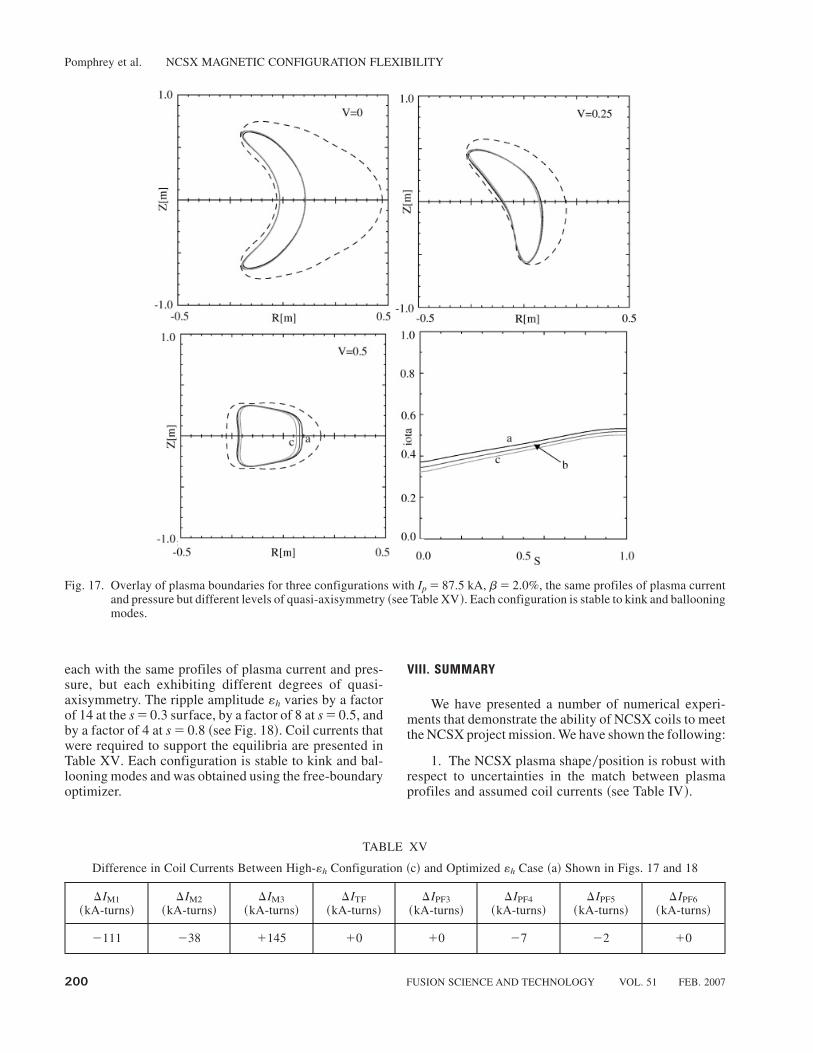
each with the same profiles of plasma current and pres-sure, but each exhibiting different degrees of quasi-axisymmetry. The ripple amplitude «h varies by a factorof 14 at the s � 0.3 surface, by a factor of 8 at s � 0.5, andby a factor of 4 at s � 0.8 ~see Fig. 18!. Coil currents thatwere required to support the equilibria are presented inTable XV. Each configuration is stable to kink and bal-looning modes and was obtained using the free-boundaryoptimizer.
VIII. SUMMARY
We have presented a number of numerical experi-ments that demonstrate the ability of NCSX coils to meetthe NCSX project mission. We have shown the following:
1. The NCSX plasma shape0position is robust withrespect to uncertainties in the match between plasmaprofiles and assumed coil currents ~see Table IV!.
Fig. 17. Overlay of plasma boundaries for three configurations with Ip � 87.5 kA, b� 2.0%, the same profiles of plasma currentand pressure but different levels of quasi-axisymmetry ~see Table XV!. Each configuration is stable to kink and ballooningmodes.
TABLE XV
Difference in Coil Currents Between High-«h Configuration ~c! and Optimized «h Case ~a! Shown in Figs. 17 and 18
DIM1~kA-turns!
DIM2~kA-turns!
DIM3~kA-turns!
DITF~kA-turns!
DIPF3~kA-turns!
DIPF4~kA-turns!
DIPF5~kA-turns!
DIPF6~kA-turns!
�111 �38 �145 �0 �0 �7 �2 �0
Pomphrey et al. NCSX MAGNETIC CONFIGURATION FLEXIBILITY
200 FUSION SCIENCE AND TECHNOLOGY VOL. 51 FEB. 2007

2. Using reference M45 S3 plasma profiles, there isa wide operating space of Ip, b values for which plasmassupported by NCSX coils are stable to kink and balloon-ing modes and have low helical ripple amplitude «h ~seeTable V!.
3. NCSX plasma performance is robust with respectto substantial variations in plasma current and pressureprofile shape ~see Tables VII and IX and the discussion offinite edge current in Sec. IV.B!.
4. Substantial changes in the external transform i~s!and shear i'~s! can be induced by varying currents in theNCSX coils ~see Tables XII and XIII and correspondingFigs. 13 and 14!. This provides a significant control knobfor the experimental determination of stable0unstable op-erating boundaries and the investigation of 3-D shapestabilization; see Sec. VI.
5. NCSX coils have the flexibility to control thedegree of quasi-axisymmetry, allowing exploration ofthe physics of QA plasmas; see Sec. VII.
A subset of the calculations reported in this paperwere duplicated using a related coil set named M45h.
The M45h “healed” coils upon which the as-built NCSXmodular coils are based are a subtle but important per-turbation of the M45 coils, with superior flux surfacequality. It was found that the M45 coil currents, whenused as coil currents in the M45h healed coils, produceessentially identical stable configurations with the samequality of quasi-axisymmetry for states at the corners offlexibility space ~the S1, S2, and S3 states in the Ip-bscans and states with a� 0.5 in the current profile scansand g� 0.8 in the pressure profile scans!. This was to beexpected since the healing of resonant fields that ledfrom M45 to M45h ~Ref. 13! required only minor defor-mations of the M45 coils, and hence minor changes in theequilibrium fields produced by these coils.
ACKNOWLEDGMENT
This work is supported by the U.S. Department of Energy,contract DE-AC02-76CH03073.
REFERENCES
1. D. STRICKLER et al., “Integrated Plasma and Coil Opti-mization for Compact Stellarators,” Proc. 19th IAEA FusionEnergy Conf., Lyon, France, Paper FT0P2-06 ~2002!.
2. S. P. HIRSHMAN and J. C. WHITSON, “Steepest-DescentMoment Method for 3D Magnetohydrodynamic Equilibria,”Phys. Fluids, 26, 3553 ~1983!.
3. D. V. ANDERSON, A. COOPER, U. SCHWENN, and R.GRUBER, Proc. Joint Varenna-Lausanne Int. Workshop onTheory of Fusion Plasmas, p. 93, Editrice Compositori, Bologna,Italy ~1988!.
4. R. SANCHEZ, S. P. HIRSHMAN, J. C. WHITSON, andA. S. WARE, “COBRA: An Optimized Code for Fast Analysisof Ideal Ballooning Stability of 3D Magnetic Equilibria,” J.Comput. Phys., 161, 576 ~2000!.
5. V. V. NEMOV, S. V. KASILOV, W. KERNBICHLER, andM. F. HEYN, “Evaluation of 10n Neoclassical Transport inStellarators,” Phys. Plasmas, 6, 4622 ~1999!.
6. M. C. ZARNSTORFF et al., “Physics of the CompactAdvanced Stellarator NCSX,” Plasma Phys. Control. Fusion,43, A237 ~2001!.
7. E. A. LAZARUS et al., “Simulation of a Discharge for theNCSX Stellarator,” Fusion Sci. Technol., 46, 209 ~2004!.
8. D. R. MIKKELSEN et al., “Assessment of Transport inNCSX,” Fusion Sci. Technol., 51, 166 ~2007!.
9. M. I. MIKHAILOV and V. D. SHAFRANOV, “Stable Cur-rent Profile in a Stellarator with Shear,” Nucl. Fusion, 30, 413~1990!.
Fig. 18. Values of «h ~%! as a function of toroidal flux for threeconfigurations, each with Ip � 87.5 kA, b � 2.0%,each using the same profiles of plasma current andpressure, and each stable to kink and ballooning modes.Curve labeling is consistent with Fig. 17. The config-uration corresponding to the black curve was origi-nally obtained as part of the Ip-b scan discussed inSec. III and presented in Tables IV and V.
Pomphrey et al. NCSX MAGNETIC CONFIGURATION FLEXIBILITY
FUSION SCIENCE AND TECHNOLOGY VOL. 51 FEB. 2007 201
10. G.-Y. FU et al., “Ideal Magnetohydrodynamic Stability ofNCSX,” Fusion Sci. Technol., 51, 218 ~2007!.
11. D. MIKKELSEN, Personal Communication ~2001!.
12. R. JAENICKE, “Operational Boundaries on the StellaratorW7-AS at the Beginning of the Divertor Experiments,” Proc.
18th IAEA Fusion Energy Conf., Sorrento, Italy, October 4–10,2000, Paper CN-770OV403, International Atomic EnergyAgency, Vienna, Austria ~2000!.
13. S. R. HUDSON et al., “Constructing Integrable High-Pressure Full-Current Free-Boundary Stellarator Magnethydro-dynamic Equilibrium Solutions,” Nucl. Fusion, 43, 1040 ~2003!.
Pomphrey et al. NCSX MAGNETIC CONFIGURATION FLEXIBILITY
202 FUSION SCIENCE AND TECHNOLOGY VOL. 51 FEB. 2007