ncspa installation manual
TRANSCRIPT
InstallationManual for➤ Corrugated Steel Pipe
➤ Pipe Arches
➤ Structural Plate
NAT I O NA L CO R RU G AT E D ST E E L PI P E AS S O C I AT I O N
08 I
nsta
llMan
00
INSTALLATION MANUAL — NCSPA
The NCSPA Installation Manual is not a copyrighted publication. If excerpted or copied, credit to the source would be appreciated.
* * *
The information contained in this Installation Manual is theproduct of industry experience and practice. The methods usedto install corrugated steel pipe can affect both its effectivenessand useful life. The situations described in this publication andthe suggested techniques for installation are general sugges-tions and guidelines intended to alert installers to the need forcareful review of on-site conditions. Each installation willrequire its own individual evaluation. The statements ordescriptions provided herein are for general information only.The National Corrugated Steel Pipe Association assumes noresponsibility for their use.
* * *
NATIONAL CORRUGATED STEEL PIPE ASSOCIATION
1255 Twenty-Third Street, NW, Suite 200Washington, DC 20037-1174
Phone: 202/452-1700 • Fax: 202/833-3636E-mail: [email protected] • Web: www.ncspa.org
TABLE OF CONTENTSFOREWORD .............................................................................................. 3
BASIC PRINCIPLES FOR PROPERCONSTRUCTION AND INSTALLATION ............................................. 4
LOCATION ................................................................................................. 5
EXCAVATION............................................................................................. 5Embankment Condition.................................................................. 5Trench Condition............................................................................ 5Trench Width and Shape ................................................................ 6
PREPARING FOUNDATIONS................................................................. 7Handling Poor Foundations............................................................ 7Uneven Foundations....................................................................... 8Soft Foundations............................................................................. 9Pockets of Unstable Soil ................................................................ 9Swampy Foundations ................................................................... 10Improved Foundations.................................................................. 10Settlement Under High Fill Loads ............................................... 10Rock Foundations......................................................................... 11Arch Foundations ......................................................................... 11
ASSEMBLY............................................................................................... 12Unloading and Handling .............................................................. 12Connecting Bands ........................................................................ 12Installing Connecting Bands ........................................................ 12Typical Connecting Bands ........................................................... 14Gaskets ......................................................................................... 16Mastic ........................................................................................... 17Asphalt Coated Pipe ..................................................................... 17Paved-Invert Pipe.......................................................................... 17Full Lined Pipe............................................................................. 18Polymer Coated Pipe.................................................................... 18Pipe Arch ...................................................................................... 18Field Coated Structural Plate Structures ...................................... 18Structural Plate Structures............................................................ 18Tools Required ............................................................................. 19Erection ........................................................................................ 19Long Span Structures ................................................................... 21Lifting Assistance......................................................................... 21End Treatment .............................................................................. 21Cut End......................................................................................... 22
CSP Installation Manual 108
Ins
tallM
an00
ASSEMBLY (continued)Cut-Off Walls ............................................................................... 23End Sections ................................................................................. 24Other End Finishes ....................................................................... 24Stream Diversion .......................................................................... 24
BACKFILLING ........................................................................................ 25Backfill Material........................................................................... 25Placing the Backfill ...................................................................... 25Pipe Arches................................................................................... 30Arches........................................................................................... 30Large Diameter Structures ........................................................... 32Proper Material Placement ........................................................... 32Even Placement of Backfill.......................................................... 33Shape Control ............................................................................... 33Multiple Installations.................................................................... 34Long Span Structures ................................................................... 35Final Backfilling........................................................................... 35
COMPACTION EQUIPMENT ............................................................... 35Hand Compaction......................................................................... 35Mechanical Compactors ............................................................... 36Roller Compactors........................................................................ 36Vibrating Compactors .................................................................. 36Hydraulic Compaction ................................................................. 36Structure Protection...................................................................... 36Construction Loads ...................................................................... 37Hydraulic Protection .................................................................... 38
SUMMARY ............................................................................................... 40
SUBDRAINAGE ....................................................................................... 41Underdrain Pipe............................................................................ 41Flow Line ..................................................................................... 41Preparing the Foundation ............................................................ 41Assembly of Underdrain Pipe ...................................................... 41Proper Placement of Underdrain Pipe.......................................... 42
APPENDIX................................................................................................ 44 Culvert Grades and Outfall Treatment ......................................... 44Length of Culverts........................................................................ 44 Skew Number ............................................................................... 47
National Corrugated Steel Pipe Association 2
FOREWORDThis manual is intended for both the contractor and the engineer. It providespractical information for the installation of corrugated steel pipe as stormsewers or culverts. It also provides the necessary considerations for properdesign to achieve long term performance of the culvert or storm sewer.
Corrugated steel pipe with its high load carrying capacity, strong joints andexceptional beam strength is installed more easily than other types of con-duit. However, the correct installation procedures must be followed to insurefull investment value in the structure.
It is the intent of this manual to suggest ways and means of improvinginstallation practices. It is not intended to be used as a direct specifica-tion, but rather as a practical field guide for the installation of corrugat-ed steel pipe, pipe arch and structural plate.
Too much emphasis cannot be placed on the necessity of adequatecompaction of backfill. Faulty compaction has led to more trouble withpipe installations, flexible and rigid, than all other factors combined!
OSHA safety regulations and guidelines must be observed during all phasesof construction including foundation preparation, excavation, pipe handling,assembly and backfilling.
Additional information is available in the AISI Handbook of Steel Drainageand Highway Construction Products and ASTM Specifications A 798 and A 807.
This manual uses dual units of measure with Imperial units shown first fol-lowed by metric units in parentheses. Complex drawings or tables may beduplicated in metric.
CSP Installation Manual 3
BASIC PRINCIPLES FOR PROPER CONSTRUCTION & INSTALLATIONProject plans and specifications provide the basic requirements for construc-tion and installation. However, site conditions often vary from those antici-pated during design. The contractor and construction engineer must recog-nize these variations. Often, alternate or additional construction considera-tions are necessary. The following guidelines provide specific considerationsand details for various conditions in a step-by-step construction sequence.
The following summary will appear again near the end of the manual.However review it now as a basic outline of the steps required for a properinstallation:
1) Check alignment in relation to the plans as well as theactual site conditions.
2) Make certain the pipe length(s), necessary appurtenances,etc. are correct.
3) Excavate to the correct width, line and grade.
4) Provide a uniform, stable foundation—correct site condi-tions as necessary.
5) Unload, handle and store the pipe correctly.
6) Assemble the pipe properly—check alignment, follow spe-cial procedures for the connecting bands, gaskets, andother hardware used. (For structural plate structures,achieve properly aligned plate laps, bolt torque, andassembled dimensions.)
7) Use a suitable (granular) backfill material as required inthe plans and specifications.
8) Maintain proper backfill width.
9) Haunch the pipe properly.
10) Place and compact the backfill in 6 to 8 inches (150 to 200millimeters) of thickness of compacted lifts.
11) Install the necessary end treatment quickly to protect thepipe and your efforts.
12) Protect the structure from heavy construction equipmentloads, other heavy loads and hydraulic forces.
4 National Corrugated Steel Pipe Association
LOCATIONBefore installing any drainage structure, it is best to first recheck the plannedalignment and grade (position and percent of slope) of the pipe in relation tothe topography of the site. Even when complete construction plans are sup-plied, a careful examination of the site should be made.
EXCAVATIONEmbankment Condition
The only excavation typically required for an embankment condition is toremove the topsoil, muck and organic matter and prepare a stable foundationat the proper elevation and grade.
Trench Condition
Most storm sewers are installed in trenches. Although pipes can be easilyinstalled in a trench, there are some general guidelines that should be followed.
All trench excavation should proceed only after OSHA and other safetyrequirements are met. Trench excavation normally proceeds in the upgradedirection. Most trenching equipment is more efficiently operated in this man-ner, and pipe sections are also more easily joined when progressing in thisdirection. If excavated spoil is to be used as backfill, it should be stockpiledat a safe distance from the edge of the trench. As a general rule, when trenchwalls are unsupported, the distance from the trench edge to the toe of thestockpiled material should not be less than one-half the depth of the trench.When trench walls are protected by some form of sheeting or shoring, a safeminimum distance between the trench edge and stockpiled material must stillbe maintained, but will vary with soil and bracing types.
Care should always be exercised in the operation of equipment in the vicin-ity of an open trench. Operated too close to the trench, equipment weight andvibration may collapse the trench walls. The three phases of construction ina trench (excavation, pipe installation, and backfilling) should be scheduledin close sequence with each other. An open trench is dangerous and vulnera-ble to accidents. An open excavation can result in damage to the projectunder construction. The two main hazards that must always be considered intrenching work are:
➤ Stability of trench walls; and
➤ Water that may accumulate in the trench resulting from seepage andsurface runoff.
CSP Installation Manual 5
To minimize accidents and losses resulting from trenching operations the fol-lowing procedures should be followed:
➤ Begin excavation only when installation of pipe can immediatelyfollow.
➤ Protect trench walls to insure their stability throughout the con-struction period.
➤ Follow procedures that will keep the trench free of seepage and sur-face waters.
➤ Excavate the trench at the same rate as pipe installation with a min-imum distance, as dictated by safety, separating the two operations.
➤ Backfill the trench as soon as practicable after pipe installation.
Trench Width and Shape
The width and shape of the trench should be as shown on the plans. Anychange should be approved by the Engineer.
Generally, the trench width will be specified as 12 to 48 inches (300 to 1200millimeters) wider than the pipe. However, it must be wide enough to allowthe critical lower quadrants of the pipe to be properly backfilled (haunched).Figure 16 provides guidelines about minimum spacing between multiplestructures. These same guidelines can be used to provide the necessary widthbetween the pipe and trench wall to adequately place typical backfill. Lesserspacing may be used with slurries and other backfill materials that do notrequire mechanical compaction.
6 National Corrugated Steel Pipe Association
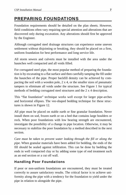
PREPARING FOUNDATIONSFoundation requirements should be detailed on the plan sheets. However,field conditions often vary requiring special attention and alterations that arediscovered only during excavation. Any alterations should first be approvedby the Engineer.
Although corrugated steel drainage structures can experience some unevensettlement without disjointing or breaking, they should be placed on a firm,uniform foundation for best performance and long service life.
All storm sewers and culverts must be installed with the area under thehaunches well compacted and all voids filled.
For corrugated steel pipe, the most popular method of preparing the founda-tion is by excavating to a flat surface and then carefully tamping the fill underthe haunches of the pipe. Proper backfill density can be achieved by com-pacting the soil with a wooden pole, 2 x 4, or the smaller sizes of pneumatictampers to eliminate all voids under the structure. See Figure 1 for typicalmethods of bedding corrugated steel structures and the 2 x 4 description.
This “flat foundation” technique works well except for larger pipe-archesand horizontal ellipses. The vee-shaped bedding technique for these struc-tures is shown in Figure 12.
All pipe must be placed on stable earth or fine granular foundation. Neverinstall them on sod, frozen earth or on a bed that contains large boulders orrock. When poor foundations with low bearing strength are encountered,investigate the possibility of a change in pipe location. Otherwise, it may benecessary to stabilize the poor foundation by a method described in the nextsection.
Care must be taken to prevent water leaking through the fill or along thepipe. When granular materials have been added for bedding, the ends of thefill should be sealed against infiltration. This can be done by bedding theends in well compacted clay or by adding some type of end treatment suchas an end section or a cut off wall.
Handling Poor Foundations
If poor or non-uniform foundations are encountered, they must be treatedcorrectly to assure satisfactory results. The critical factor is to achieve uni-formity along the pipe with a tendency for the foundation to yield under thepipe in relation to alongside the pipe.
CSP Installation Manual 7
Uneven Foundations
When the excavated grade line reveals both soft and hard spots, the founda-tion must be changed to make it as uniform as possible. Sometimes hardspots can be excavated below grade and replaced with softer material.Alternatively, it may be more economical to excavate the entire foundationslightly below grade line and replace it with suitable, uniform material. Inany event, any abrupt changes from hard to soft foundation must be avoided.
8 National Corrugated Steel Pipe Association
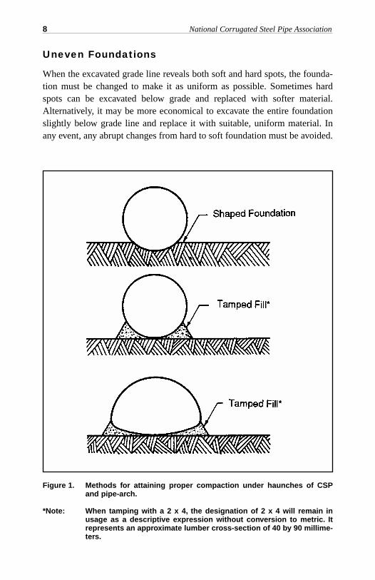
Figure 1. Methods for attaining proper compaction under haunches of CSPand pipe-arch.
*Note: When tamping with a 2 x 4, the designation of 2 x 4 will remain inusage as a descriptive expression without conversion to metric. Itrepresents an approximate lumber cross-section of 40 by 90 millime-ters.
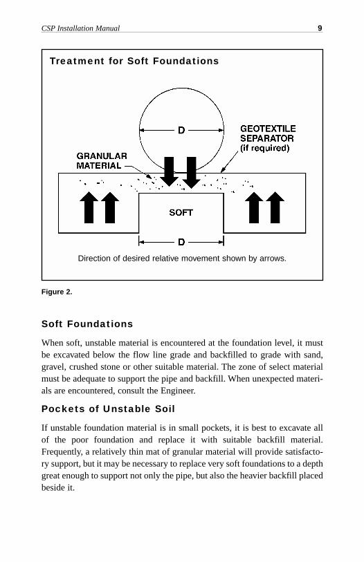
Soft Foundations
When soft, unstable material is encountered at the foundation level, it mustbe excavated below the flow line grade and backfilled to grade with sand,gravel, crushed stone or other suitable material. The zone of select materialmust be adequate to support the pipe and backfill. When unexpected materi-als are encountered, consult the Engineer.
Pockets of Unstable Soil
If unstable foundation material is in small pockets, it is best to excavate allof the poor foundation and replace it with suitable backfill material.Frequently, a relatively thin mat of granular material will provide satisfacto-ry support, but it may be necessary to replace very soft foundations to a depthgreat enough to support not only the pipe, but also the heavier backfill placedbeside it.
CSP Installation Manual 9
Figure 2.
Direction of desired relative movement shown by arrows.
Treatment for Soft Foundations
Swampy Foundations
Corrugated steel pipe must not be placed in direct contact with pipe bents orconcrete cradles that are installed to help provide a foundation. Such sup-ports, if used, should be built with a flat top and covered with an earth cush-ion. In this way the flexible structure can develop side support without con-centrating the load at any point.
Improved Foundations(soft, uneven, unstable or swampy)
Whenever a foundation is stabilized by using a coarse granular material, con-sideration of the bedding and backfill material becomes even more impor-tant. Fine materials can migrate into coarser materials and geotextile separa-tors are often required to prevent this migration.
Settlement Under High Fill Loads(camber for embankment installations)
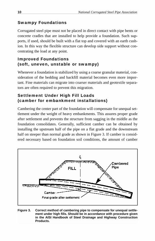
Cambering the center part of the foundation will compensate for unequal set-tlement under the weight of heavy embankments. This assures proper gradeafter settlement and prevents the structure from sagging in the middle as thefoundation consolidates. Generally, sufficient camber can be obtained byinstalling the upstream half of the pipe on a flat grade and the downstreamhalf on steeper than normal grade as shown in Figure 3. If camber is consid-ered necessary based on foundation soil conditions, the amount of camber
10 National Corrugated Steel Pipe Association
Figure 3. Correct method of cambering pipe to compensate for unequal settle-ment under high fills. Should be in accordance with procedure givenin the AISI Handbook of Steel Drainage and Highway ConstructionProducts.
must be determined by a qualified soils engineer. If the pipe is setting oncushioned rock or other adequate strength foundation, no camber is neces-sary, as settlement will be minor.
Be careful not to raise the center of the pipe above the inlet, as this will pock-et water in the pipe.
Rock Foundations
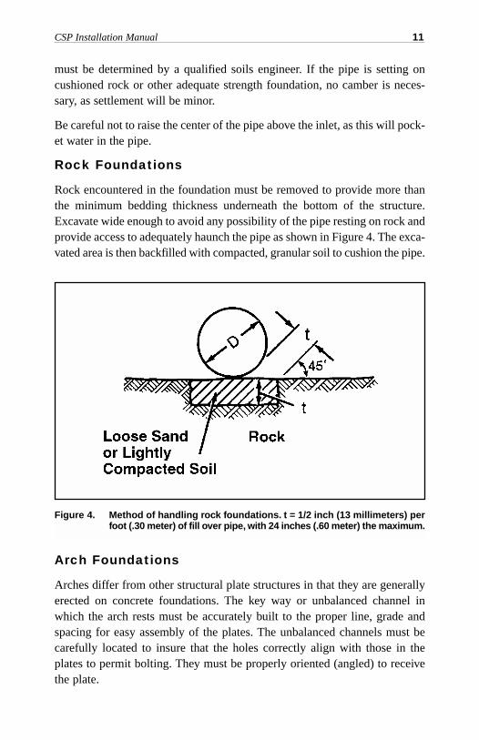
Rock encountered in the foundation must be removed to provide more thanthe minimum bedding thickness underneath the bottom of the structure.Excavate wide enough to avoid any possibility of the pipe resting on rock andprovide access to adequately haunch the pipe as shown in Figure 4. The exca-vated area is then backfilled with compacted, granular soil to cushion the pipe.
Arch Foundations
Arches differ from other structural plate structures in that they are generallyerected on concrete foundations. The key way or unbalanced channel inwhich the arch rests must be accurately built to the proper line, grade andspacing for easy assembly of the plates. The unbalanced channels must becarefully located to insure that the holes correctly align with those in theplates to permit bolting. They must be properly oriented (angled) to receivethe plate.
CSP Installation Manual 11
Figure 4. Method of handling rock foundations. t = 1/2 inch (13 millimeters) perfoot (.30 meter) of fill over pipe, with 24 inches (.60 meter) the maximum.
ASSEMBLYUnloading and handling
Pipe must never be dumped directly from a truck bed while unloading.
Although corrugated steel drainage structures withstand normal handlingthey should be handled with reasonable care. Dragging the pipe at any timemay damage the coatings. Also avoid striking rocks or hard objects whenlowering pipe into trenches.
Since corrugated steel pipes are relatively light weight, they can be handledwith light equipment. Use of slings is recommended to properly handle thepipe.
Connecting Bands
The usual method of joining two or more lengths of pipe or pipe arch is bysteel connecting bands. The bands engage the ends of each pipe section. Theyare placed to overlap each pipe section equally. The corrugations on the bandmust fit into the corrugations of each pipe. Tightening of bolts draws theband tightly around the adjacent ends of pipe lengths, providing an integraland continuous structure.
One piece bands are used for most installations of smaller sizes of pipe.“Two-piece” bands are used on larger diameter pipe and when installationconditions are difficult. “Rods and Lugs” are used on levees, aerial sewersand similar installations where bands that provide tighter and stronger jointsare essential.
Typical bands, and their method of installation, are illustrated in Figures 4Ato 4E. Specially fabricated bolted, welded or riveted connectors can be sup-plied for use in jacking and for special or unusual conditions. If the pipe endshave been match marked by the fabricator, then they must be installed in theproper sequence.
Installing Connecting Bands
During the construction of a corrugated steel pipe system, care must be givento the assembly of joints to control both infiltration and exfiltration. Bothprocesses will have an effect upon backfill materials since soil particlemigration can occur. This is particularly true when fine “rained soils (finesands and silts) are present in the backfill material. When necessary, a gas-ket, a geotextile wrap, or both can also be used to control infiltration of fines.
12 National Corrugated Steel Pipe Association
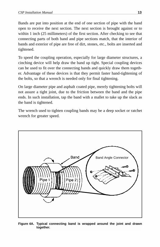
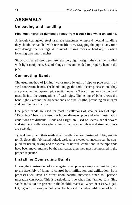
Bands are put into position at the end of one section of pipe with the bandopen to receive the next section. The next section is brought against or towithin 1 inch (25 millimeters) of the first section. After checking to see thatconnecting parts of both band and pipe sections match, that the interior ofbands and exterior of pipe are free of dirt, stones, etc., bolts are inserted andtightened.
To speed the coupling operation, especially for large diameter structures, acinching device will help draw the band up tight. Special coupling devicescan be used to fit over the connecting bands and quickly draw them togeth-er. Advantage of these devices is that they permit faster hand-tightening ofthe bolts, so that a wrench is needed only for final tightening.
On large diameter pipe and asphalt coated pipe, merely tightening bolts willnot assure a tight joint, due to the friction between the band and the pipeends. In such installation, tap the band with a mallet to take up the slack asthe band is tightened.
The wrench used to tighten coupling bands may be a deep socket or ratchetwrench for greater speed.
CSP Installation Manual 13
Figure 4A. Typical connecting band is wrapped around the joint and drawntogether.
Band Angle Connector
14 National Corrugated Steel Pipe Association
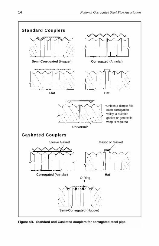
Figure 4B. Standard and Gasketed couplers for corrugated steel pipe.
Standard Couplers
Gasketed Couplers
Semi-Corrugated (Hugger) Corrugated (Annular)
Corrugated (Annular)
Sleeve Gasket Mastic or Gasket
O-Ring
Semi-Corrugated (Hugger)
Hat
Flat Hat
Universal*
*Unless a dimple fillseach corrugationvalley, a suitablegasket or geotextilewrap is required
CSP Installation Manual 15
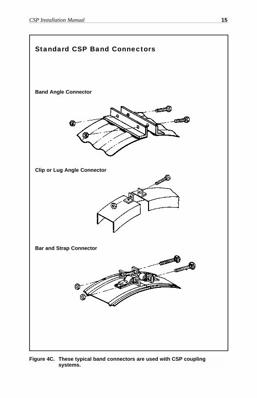
Figure 4C. These typical band connectors are used with CSP coupling systems.
Standard CSP Band Connectors
Band Angle Connector
Clip or Lug Angle Connector
Bar and Strap Connector
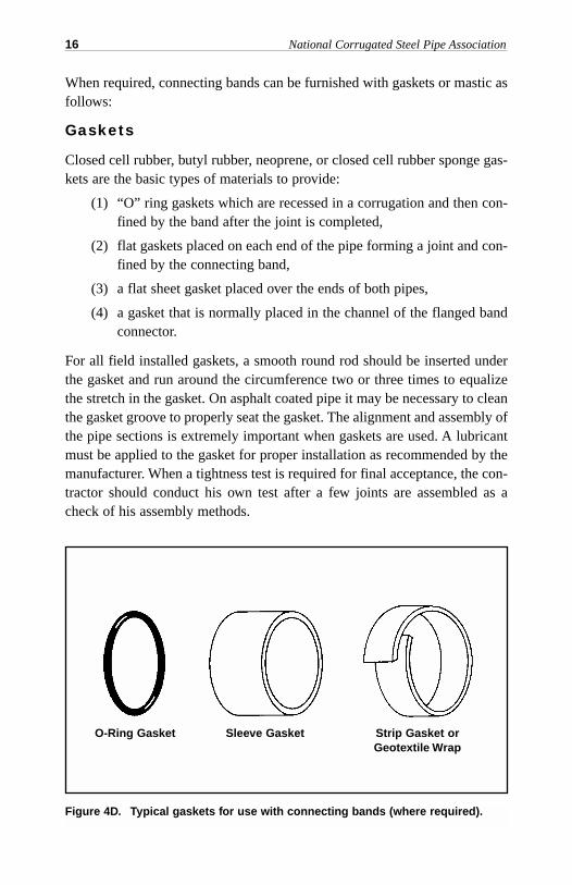
When required, connecting bands can be furnished with gaskets or mastic asfollows:
Gaskets
Closed cell rubber, butyl rubber, neoprene, or closed cell rubber sponge gas-kets are the basic types of materials to provide:
(1) “O” ring gaskets which are recessed in a corrugation and then con-fined by the band after the joint is completed,
(2) flat gaskets placed on each end of the pipe forming a joint and con-fined by the connecting band,
(3) a flat sheet gasket placed over the ends of both pipes,
(4) a gasket that is normally placed in the channel of the flanged bandconnector.
For all field installed gaskets, a smooth round rod should be inserted underthe gasket and run around the circumference two or three times to equalizethe stretch in the gasket. On asphalt coated pipe it may be necessary to cleanthe gasket groove to properly seat the gasket. The alignment and assembly ofthe pipe sections is extremely important when gaskets are used. A lubricantmust be applied to the gasket for proper installation as recommended by themanufacturer. When a tightness test is required for final acceptance, the con-tractor should conduct his own test after a few joints are assembled as acheck of his assembly methods.
16 National Corrugated Steel Pipe Association
Figure 4D. Typical gaskets for use with connecting bands (where required).
O-Ring Gasket Sleeve Gasket Strip Gasket orGeotextile Wrap
Mastic
Mastic may be applied to the connecting band or pipe prior to placing and ten-sioning the connecting band. A sufficient amount of mastic should be used tofill the joint space between the corrugation and band with some squeeze out.
Asphalt Coated Pipe
Although asphalt coated corrugated pipe is laid and jointed in the same man-ner as galvanized pipe, special attention should be given to attaching the con-necting bands. Contacting surfaces of the bands and pipe may need to belubricated. This allows the band to easily slip around the pipe so it can bedrawn more firmly into place. Lubrication is especially needed when sur-faces are cold. In addition, tapping the bands with a mallet during tighteningwill help to assure proper joints.
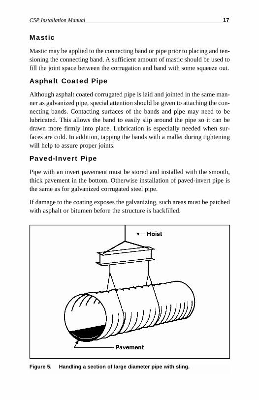
Paved-Invert Pipe
Pipe with an invert pavement must be stored and installed with the smooth,thick pavement in the bottom. Otherwise installation of paved-invert pipe isthe same as for galvanized corrugated steel pipe.
If damage to the coating exposes the galvanizing, such areas must be patchedwith asphalt or bitumen before the structure is backfilled.
CSP Installation Manual 17
Figure 5. Handling a section of large diameter pipe with sling.
Full Lined Pipe
100% paved pipe is basically an extension of the paving in paved invert pipeto include the entire periphery. Since the paving covers all interior corruga-tions, the pipe should not be subjected to rough handling. Smooth steel linedpipe is fabricated with smooth steel liner suitably coated.
When installations are to be made in hot weather, pipe lengths can be orderedwith an additional white coating on the pipe exterior to reduce the tempera-ture of the pipe, if it is to be exposed to the bright summer sun for long peri-ods. Prolonged storage of fully lined pipe should be avoided in any season.
Polymer Coated Pipe
Polymer coated pipe shall be installed in the same manner as asphalt coatedpipe. Lubrication is not required unless gaskets are used.
Pipe Arch
Corrugated steel pipe arch structures are installed in the same manner asround pipe. Recommendations regarding placement and connecting of vari-ous types of pipe also apply to pipe-arch. However, because of its shape, par-ticular care should be taken in installing pipe arch structures. (See page 30.)Because of their multiple radius shape, pipe arches are not intended forrestrictive leakage or high cover applications.
Field Coated Structural Plate Structures
Field coated asphalt mastic coatings shall be applied per the manufacturer'sapplication instructions and material safety data sheet (MSDS).
The coating shall be applied to a clean surface, free of dirt, oil, grease, orother foreign matter, when the atmospheric temperature is above 40°F (4°C).and the humidity is low enough that the surface of the metal can be kept dry.
Coating may be applied by spray, brush, or trowel as required by the manu-facturer to attain a uniform dry thickness of 0.05 inch ( 1.3 millimeters).
Structural Plate Structures
The primary difference between structural plate and factory fabricated pipeis that structural plate is assembled by bolting together fabricated corrugatedsteel plates at the installation site. Trucks usually deliver the stacks of curvedplates to the site and equipment is required to lift such stacks intact.Individual plates may be removed and positioned with light equipment.
18 National Corrugated Steel Pipe Association
Preparation of the base and backfilling are the same as those described forcorrugated steel pipe.
Tools Required
Proper tools will speed the erection of structural plate. They include struc-tural and socket wrenches, lining bars, drift pins and handling hooks.
If power wrenches are used, check bolt tightness very carefully as it is easyfor these wrenches to get out of adjustment. The proper use of a long handledstructural socket wrench or torque wrench will insure that bolts are properlytightened.
Erection
Every structural plate structure is shipped complete with all necessary plates,bolts and nuts for erection. Inside one of the containers of bolts (clearlymarked) are detailed erection instructions, showing the position of each plateand order of assembly.
CSP Installation Manual 19
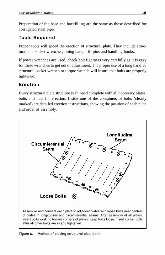
Assemble and connect each plate to adjacent plates with loose bolts near centersof plates in longitudinal and circumferential seams. After assembly of all plates,insert bolts working toward corners of plates. Keep bolts loose. Insert corner boltsafter all other bolts are in and tightened.
Figure 6. Method of placing structural plate bolts.
Structural plate structures should be assembled with as few bolts as possibleuntil all plates are in place. Three or four “finger tight” bolts placed near thecenter of each plate along the longitudinal and circumferential seams are suf-ficient. (See Figure 6.)
After several rings (a ring is a circumferential series of plates required tomake one continuous circle) have been assembled, the remaining bolts canbe installed, but not torqued tight, always working from the center of a seamtoward the corner of the plates. Do not insert corner bolts until all others arein place and tightened. Aligning bolt holes with a bar is done more easilywhen the bolts are loose. Drifting, with a drift pin, is best done when theadjacent bolts are tight.
Tighten nuts progressively and uniformly, starting at one end of the structure,after all plates have been assembled. Then repeat the operation to be surebolts are tight. From 100 to 300 foot-pounds (140 to 400 newton~meters) oftorque should be applied. Do not over torque.
A good plate fit is far more important than high bolt torque. Some structuresrequire alternate procedures—refer to the manufacturer's assembly instructions.
20 National Corrugated Steel Pipe Association
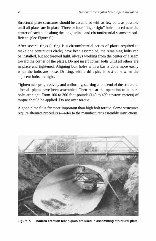
Figure 7. Modern erection techniques are used in assembling structural plate.
Long Span Structures
Long span structures are large structural plate pipes or arches to which gen-eral structural plate assembly requirements apply. However, because of theirsize, the plates need to be tightly bolted as they are placed. Because much ofthe strength of these structures is derived from their shape, the rise and spanof the assembled shape must be within 2 percent of the design dimensionsprior to backfilling. With any long span structure, the manufacturer shouldcover specific requirements in a pre-construction conference.
Lifting Assistance
Generally speaking, if the diameter or rise of the structural plate structure isbeyond the extended arms of the average construction worker, he should beprovided some type of lifting equipment or scaffolding. If powered liftingequipment is not feasible or readily available, here are other ways of simpli-fying assembly:
1. An “A” frame, utilizing man-powered block and tackle.
2. A lifting hoist built into the bed of a flat-bed truck.
3. Bed of a flat-bed truck, if size of structure permits the truck to bedriven inside.
4. A combination of scaffolding built inside the structure and laddersoutside. Or a flat-bed truck plus scaffolding.
End Treatment
In many cases, the ends of corrugated steel pipe that project, through theembankment can be simply specified as square ends, that is, not beveled orskewed. The square end is lowest in cost and readily adaptable to road widen-ing projects. For larger structures, the slope can be warped around the endsto avoid severe skews or bevels on the pipe end in many cases. When desiredfor hydraulic considerations, flared end sections can be furnished for shopfabricated pipe. Such end sections can be bolted directly to the pipe.
When specified, ends of corrugated steel structures can be cut (beveled orskewed) to match the embankment slope. However, cutting the ends destroysthe ability of the end portion of the structure to resist ring compression anduplift forces. Thus, ends with severe cuts must be reinforced, particularly onlarger structures. For complete details, see the AISI Handbook of SteelDrainage & Highway Construction Products.
CSP Installation Manual 21
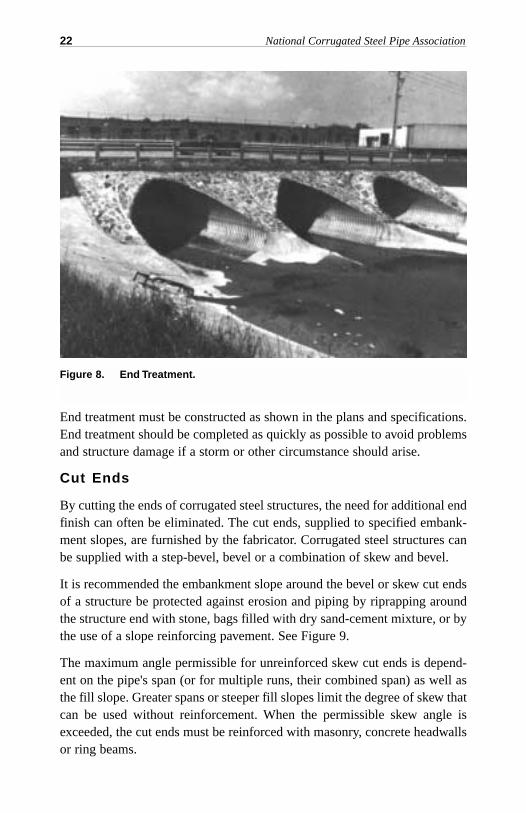
End treatment must be constructed as shown in the plans and specifications.End treatment should be completed as quickly as possible to avoid problemsand structure damage if a storm or other circumstance should arise.
Cut Ends
By cutting the ends of corrugated steel structures, the need for additional endfinish can often be eliminated. The cut ends, supplied to specified embank-ment slopes, are furnished by the fabricator. Corrugated steel structures canbe supplied with a step-bevel, bevel or a combination of skew and bevel.
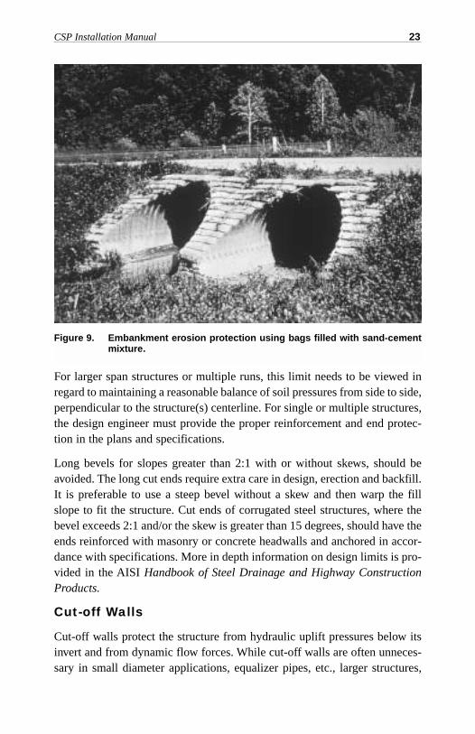
It is recommended the embankment slope around the bevel or skew cut endsof a structure be protected against erosion and piping by riprapping aroundthe structure end with stone, bags filled with dry sand-cement mixture, or bythe use of a slope reinforcing pavement. See Figure 9.
The maximum angle permissible for unreinforced skew cut ends is depend-ent on the pipe's span (or for multiple runs, their combined span) as well asthe fill slope. Greater spans or steeper fill slopes limit the degree of skew thatcan be used without reinforcement. When the permissible skew angle isexceeded, the cut ends must be reinforced with masonry, concrete headwallsor ring beams.
22 National Corrugated Steel Pipe Association
Figure 8. End Treatment.
For larger span structures or multiple runs, this limit needs to be viewed inregard to maintaining a reasonable balance of soil pressures from side to side,perpendicular to the structure(s) centerline. For single or multiple structures,the design engineer must provide the proper reinforcement and end protec-tion in the plans and specifications.
Long bevels for slopes greater than 2:1 with or without skews, should beavoided. The long cut ends require extra care in design, erection and backfill.It is preferable to use a steep bevel without a skew and then warp the fillslope to fit the structure. Cut ends of corrugated steel structures, where thebevel exceeds 2:1 and/or the skew is greater than 15 degrees, should have theends reinforced with masonry or concrete headwalls and anchored in accor-dance with specifications. More in depth information on design limits is pro-vided in the AISI Handbook of Steel Drainage and Highway ConstructionProducts.
Cut-off Walls
Cut-off walls protect the structure from hydraulic uplift pressures below itsinvert and from dynamic flow forces. While cut-off walls are often unneces-sary in small diameter applications, equalizer pipes, etc., larger structures,
CSP Installation Manual 23
Figure 9. Embankment erosion protection using bags filled with sand-cementmixture.
pipes with a large bottom radius such as pipe arches or other pipes in appli-cations where currents are swift or water levels rise or fall quickly are moresusceptible to hydraulic damage. These latter conditions should be investi-gated by the design engineer.
End Sections
End Sections provide a practical and economical method of finishing cul-verts. Sections are attached to the pipe or pipe arch ends by simple connec-tors—similar to coupling bands used in joining pipe sections—and can becompletely salvaged if lengthening or relocating the culvert is necessary.
Other End Finishes
While corrugated steel structures do not usually require headwalls, practical-ly any type can be used. Where embankments must be confined, full or half-high steel sheeting headwalls are both efficient and economical. If requiredfor appearance, concrete or masonry headwalls or half headwalls can also beused on all types of corrugated steel drainage structures. However, as is thecase with rigid pipe, the headwalls must be supported by an adequate foun-dation.
Stream Diversion
If the stream is temporarily diverted during construction, the diversion ditchor temporary drainage pipe must be adequate to carry the storm flow. Shortconstruction times of course are helpful in limiting this exposure. The pipeinstallation must be protected from storm flows by a temporary dike, coffer-dam, etc.
If the structure must carry the flow during the construction stage, theupstream end must be protected with the proper end treatment, etc. to ensurethat the flow is not diverted around or beside the pipe thereby scouring outbackfill as it is placed or floating the pipe. In phased construction, it is desir-able to construct and backfill the upstream end first. (See HydraulicProtection, page 38.)
24 National Corrugated Steel Pipe Association
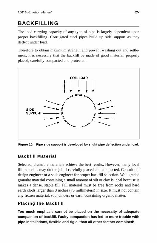
BACKFILLINGThe load carrying capacity of any type of pipe is largely dependent uponproper backfilling. Corrugated steel pipes build up side support as theydeflect under load.
Therefore to obtain maximum strength and prevent washing out and settle-ment, it is necessary that the backfill be made of good material, properlyplaced, carefully compacted and protected.
Backfill Material
Selected, drainable materials achieve the best results. However, many localfill materials may do the job if carefully placed and compacted. Consult thedesign engineer or a soils engineer for proper backfill selection. Well gradedgranular material containing a small amount of silt or clay is ideal because ismakes a dense, stable fill. Fill material must be free from rocks and hardearth clods larger than 3 inches (75 millimeters) in size. It must not containany frozen material, sod, cinders or earth containing organic matter.
Placing the Backfill
Too much emphasis cannot be placed on the necessity of adequatecompaction of backfill. Faulty compaction has led to more trouble withpipe installations, flexible and rigid, than all other factors combined!
CSP Installation Manual 25
Figure 10. Pipe side support is developed by slight pipe deflection under load.
For trench installations, backfill must follow as closely behind the excavationand assembly stages as possible. Embankment installations typically arebackfilled after the entire structure, or a major portion of it, is assembled.Unless the embankment and backfill materials are placed simultaneously,one must be benched so the other can be compacted against it.
The backfill should be carefully compacted under the haunches (lower partof structure exterior, below widest part); special care should be taken indoing this for pipe-arches.
Continue placing the backfill equally on both sides of the pipe in 6 to 8 inch-es (.15 to .20 meters) of compacted layers thoroughly compacting each layerto a 90% Standard Proctor density (AASHTO T99). Such compacted layersmust extend to the limits shown on the plans on each side of the structure, orto the side of a trench, or to the natural ground line.
One problem in backfilling is the frequent inclination of installing crews tohave the backfill material dumped in piles around the pipe. Such piles ofmaterial are seldom spread so that there is a maximum depth of a 6 to 8 inch-es (.15 to .20 meters) of compacted layer. If the filling crew works too fast,the compaction crew never has a chance to adequately compact the firstmaterial before more is placed in the trench. If backfill material is properlyselected, well placed and then adequately compacted. there is little danger ofanything going wrong with the installation. See Figure 11.
Backfill must be placed and fully compacted to the minimum cover levelover the structure before the pipe is subjected to highway or light construc-tion loads. When construction equipment that exceeds legal highwayloads will cross the pipe, an extra thickness of compacted fill, beyondthat required for minimum or planned cover, is required. SeeConstruction Loads, page 37.
26 National Corrugated Steel Pipe Association
CSP Installation Manual 27
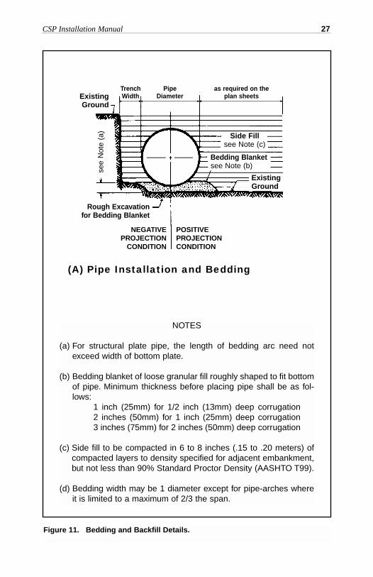
Figure 11. Bedding and Backfill Details.
NOTES
(a) For structural plate pipe, the length of bedding arc need notexceed width of bottom plate.
(b) Bedding blanket of loose granular fill roughly shaped to fit bottomof pipe. Minimum thickness before placing pipe shall be as fol-lows:
1 inch (25mm) for 1/2 inch (13mm) deep corrugation2 inches (50mm) for 1 inch (25mm) deep corrugation3 inches (75mm) for 2 inches (50mm) deep corrugation
(c) Side fill to be compacted in 6 to 8 inches (.15 to .20 meters) ofcompacted layers to density specified for adjacent embankment,but not less than 90% Standard Proctor Density (AASHTO T99).
(d) Bedding width may be 1 diameter except for pipe-arches whereit is limited to a maximum of 2/3 the span.
see
Not
e (a
)ExistingGround
TrenchWidth
PipeDiameter
as required on the plan sheets
POSITIVEPROJECTIONCONDITION
NEGATIVEPROJECTION
CONDITION
(A) Pipe Installation and Bedding
Side Fillsee Note (c)
ExistingGround
Bedding Blanketsee Note (b)
Rough Excavationfor Bedding Blanket
28 National Corrugated Steel Pipe Association
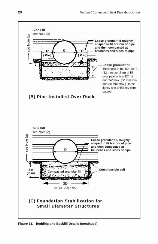
Figure 11. Bedding and Backfill Details (continued).
see
Not
e (a
)se
e N
ote
(a)
Side Fillsee Note (c)
Side Fillsee Note (c)
Loose granular fillThickness to be 1/2” per ft.(13 mm per .3 m) of fillover pipe with a 12” min.and 24” max. (30 mm min.and 60 mm max.). To belightly and uniformly com-pacted
Loose granular fill roughlyshaped to fit bottom of pipeand then compacted athaunches and sides of pipe
Loose granular fill, roughlyshaped to fit bottom of pipeand then compacted athaunches and sides of pipe
Compressible soilCompacted granular fill
2’±(.6 m)
(B) Pipe Installed Over Rock
(C) Foundation Stabilization forSmall Diameter Structures
3Dor as planned
D
CSP Installation Manual 29
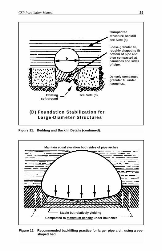
Figure 12. Recommended backfilling practice for larger pipe arch, using a vee-shaped bed.
Figure 11. Bedding and Backfill Details (continued).
Compacted structure backfillsee Note (c)
see Note (d)
Loose granular fill,roughly shaped to fitbottom of pipe andthen compacted athaunches and sidesof pipe.
Densely compactedgranular fill underhaunches.
Existing soft ground
Stable but relatively yielding
Compacted to maximum density under haunches
Maintain equal elevation both sides of pipe arches
(D) Foundation Stabilization forLarge-Diameter Structures
Pipe Arches
Special attention must be given to compaction of the backfill under thehaunches of the pipe arch. A softer or yielding foundation under the bottom,as compared to the corners, is essential. See Figure 12. A vee-shaped bed forlarger pipe arches is recommended.
Arches
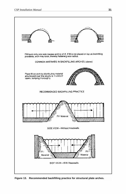
Care must be taken in backfilling arches, especially half-circle arches,because they have a tendency to shift sideways or to peak under backfillingloads. The ideal way is to cover an arch in layers-each layer conforming tothe shape of the arch. If one side is backfilled more than the other, the archwill move away from the larger load. If both sides are backfilled equally andtamped thoroughly, the top of the arch may peak unless enough fill has beenplaced over it to resist the upward thrust. These precautions apply also toother corrugated steel structures, but to a lesser degree.
When backfilling arches before headwalls are placed, the first materialshould be placed midway between the ends of the arch, forming as narrow aramp as possible until the top of the arch is reached. The ramp should be builtevenly from both sides and the backfill material should be thoroughly com-pacted as it is placed. After the two ramps have been built to the depth spec-ified to the top of the arch, the remainder of the backfill should be placed andcompacted by extending the ramp both ways from the center to the ends, andas evenly as practicable on both sides of the arch.
If the headwalls are built before the arch is backfilled, the backfill materialshould first be placed adjacent to each headwall, placing and compactingmaterial uniformly on both sides of the structure until the top of the arch isreached. Then backfill should proceed toward the center by extending theramp; with care being taken to place and compact the material evenly on bothsides of the arch. Top loading will help control peaking.
30 National Corrugated Steel Pipe Association
CSP Installation Manual 31
Figure 13. Recommended backfilling practice for structural plate arches.
32 National Corrugated Steel Pipe Association
Large Diameter Structures (Embankment Installations)
Large diameter structures are not to be confused with Long Span Structures(see page 35).
Proper Material Placement
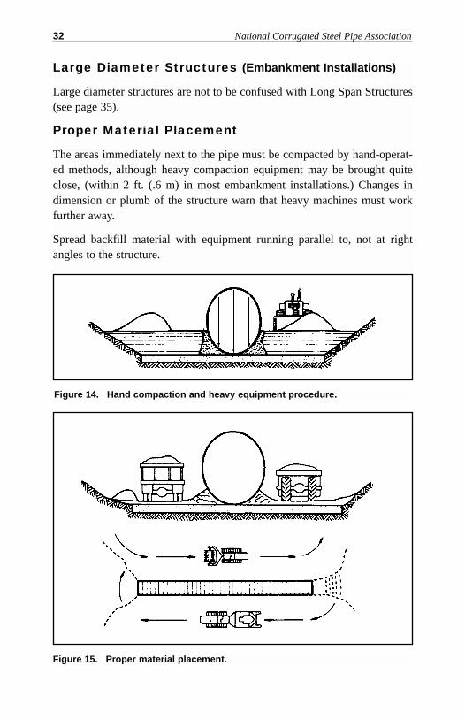
The areas immediately next to the pipe must be compacted by hand-operat-ed methods, although heavy compaction equipment may be brought quiteclose, (within 2 ft. (.6 m) in most embankment installations.) Changes indimension or plumb of the structure warn that heavy machines must workfurther away.
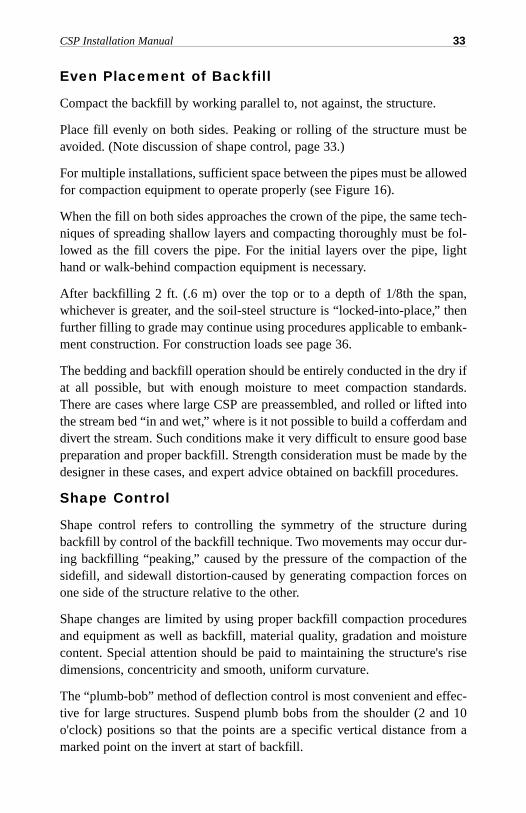
Spread backfill material with equipment running parallel to, not at rightangles to the structure.
Figure 15. Proper material placement.
Figure 14. Hand compaction and heavy equipment procedure.
Even Placement of Backfill
Compact the backfill by working parallel to, not against, the structure.
Place fill evenly on both sides. Peaking or rolling of the structure must beavoided. (Note discussion of shape control, page 33.)
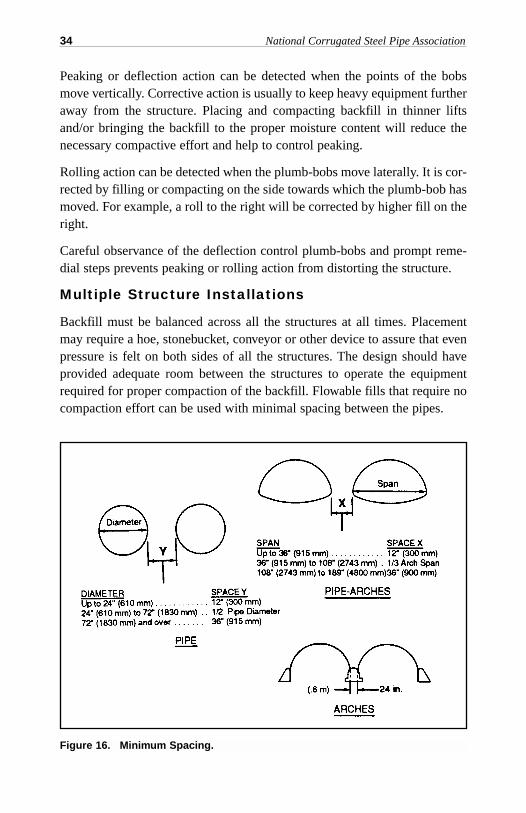
For multiple installations, sufficient space between the pipes must be allowedfor compaction equipment to operate properly (see Figure 16).
When the fill on both sides approaches the crown of the pipe, the same tech-niques of spreading shallow layers and compacting thoroughly must be fol-lowed as the fill covers the pipe. For the initial layers over the pipe, lighthand or walk-behind compaction equipment is necessary.
After backfilling 2 ft. (.6 m) over the top or to a depth of 1/8th the span,whichever is greater, and the soil-steel structure is “locked-into-place,” thenfurther filling to grade may continue using procedures applicable to embank-ment construction. For construction loads see page 36.
The bedding and backfill operation should be entirely conducted in the dry ifat all possible, but with enough moisture to meet compaction standards.There are cases where large CSP are preassembled, and rolled or lifted intothe stream bed “in and wet,” where is it not possible to build a cofferdam anddivert the stream. Such conditions make it very difficult to ensure good basepreparation and proper backfill. Strength consideration must be made by thedesigner in these cases, and expert advice obtained on backfill procedures.
Shape Control
Shape control refers to controlling the symmetry of the structure duringbackfill by control of the backfill technique. Two movements may occur dur-ing backfilling “peaking,” caused by the pressure of the compaction of thesidefill, and sidewall distortion-caused by generating compaction forces onone side of the structure relative to the other.
Shape changes are limited by using proper backfill compaction proceduresand equipment as well as backfill, material quality, gradation and moisturecontent. Special attention should be paid to maintaining the structure's risedimensions, concentricity and smooth, uniform curvature.
The “plumb-bob” method of deflection control is most convenient and effec-tive for large structures. Suspend plumb bobs from the shoulder (2 and 10o'clock) positions so that the points are a specific vertical distance from amarked point on the invert at start of backfill.
CSP Installation Manual 33
Peaking or deflection action can be detected when the points of the bobsmove vertically. Corrective action is usually to keep heavy equipment furtheraway from the structure. Placing and compacting backfill in thinner liftsand/or bringing the backfill to the proper moisture content will reduce thenecessary compactive effort and help to control peaking.
Rolling action can be detected when the plumb-bobs move laterally. It is cor-rected by filling or compacting on the side towards which the plumb-bob hasmoved. For example, a roll to the right will be corrected by higher fill on theright.
Careful observance of the deflection control plumb-bobs and prompt reme-dial steps prevents peaking or rolling action from distorting the structure.
Multiple Structure Installations
Backfill must be balanced across all the structures at all times. Placementmay require a hoe, stonebucket, conveyor or other device to assure that evenpressure is felt on both sides of all the structures. The design should haveprovided adequate room between the structures to operate the equipmentrequired for proper compaction of the backfill. Flowable fills that require nocompaction effort can be used with minimal spacing between the pipes.
34 National Corrugated Steel Pipe Association
Figure 16. Minimum Spacing.
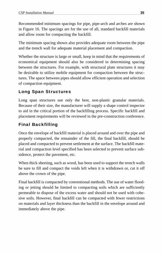
Recommended minimum spacings for pipe, pipe-arch and arches are shownin Figure 16. The spacings are for the use of all, standard backfill materialsand allow room for compacting the backfill.
The minimum spacing shown also provides adequate room between the pipeand the trench wall for adequate material placement and compaction.
Whether the structure is large or small, keep in mind that the requirements ofeconomical equipment should also be considered in determining spacingbetween the structures. For example, with structural plate structures it maybe desirable to utilize mobile equipment for compaction between the struc-tures. The space between pipes should allow efficient operation and selectionof compaction equipment.
Long Span Structures
Long span structures use only the best, non-plastic granular materials.Because of their size, the manufacturer will supply a shape control inspectorto aid in the critical portion of the backfilling process. Specific backfill andplacement requirements will be reviewed in the pre-construction conference.
Final Backfilling
Once the envelope of backfill material is placed around and over the pipe andproperly compacted, the remainder of the fill, the final backfill, should beplaced and compacted to prevent settlement at the surface. The backfill mate-rial and compaction level specified has been selected to prevent surface sub-sidence, protect the pavement, etc.
When thick sheeting, such as wood, has been used to support the trench wallsbe sure to fill and compact the voids left when it is withdrawn or, cut it offabove the crown of the pipe.
Final backfill is compacted by conventional methods. The use of water flood-ing or jetting should be limited to compacting soils which are sufficientlypermeable to dispose of the excess water and should not be used with cohe-sive soils. However, final backfill can be compacted with fewer restrictionson materials and layer thickness than the backfill in the envelope around andimmediately above the pipe.
CSP Installation Manual 35
COMPACTION EQUIPMENTHand Compaction
For compacting the small areas under the haunches of a structure, a pole or2 x 4 (see note under Figure 1) is generally needed. Hand tampers for hori-zontal layers should weigh not less than 20 pounds (9 kilograms) and have atamping face not larger than 6 by 6 inches (150 x 150 millimeters).
Mechanical Compactors
Most types of power tampers are satisfactory in all except the most confinedareas. However, they must be used carefully and completely over the entirearea of each layer to obtain the desired compaction. Avoid striking the struc-ture with power tamping tools.
Roller Compactors
Where space permits, sheepsfoot (recommended for clays and silts only),rubber tired and other types of rollers—with the exception of smoothrollers—can be used to compact backfill. But the fill adjacent to the structureshould be tamped with hand or hand-held power equipment.
Vibrating Compactors
Vibrating compactors can be used effectively on all types of backfill exceptheavy clays or other plastic soils. Small walk behind equipment is especial-ly suited to trench installations.
Hydraulic Compaction
The use of water flooding and/or jetting for compacting backfill around thepipe is limited to compacting clean, granular soils. To be effective, the foun-dation below the pipe must be sufficiently permeable to carry the water downand away quickly. Backfill around and immediately above the pipe must beplaced and compacted in individual lifts of 6 to 8 inches (150 to 200 mil-limeters) of compacted thickness.
Structure Protection
Often, construction loads exceed the finished design loads for the structure.Additionally, during the various phases of assembly, backfill and construc-tion the structure typically is more vulnerable to loadings and hydraulicforces because its backfill, end treatment, etc. are not complete. The corru-gated steel structure must be properly protected.
36 National Corrugated Steel Pipe Association
Construction Loads
Frequently, it is necessary for heavy construction equipment to travel overinstalled corrugated steel structures during completion of grading, paving orother site work. Heavy construction equipment can impose concentratedloads far in excess of those the structure is designed to carry.
Adequate protection of the corrugated steel structure may require more thanfinished design fill. The amount of additional fill needed depends on theequipment axle loads as well as the frequency of use.
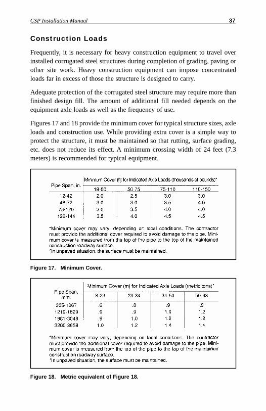
Figures 17 and 18 provide the minimum cover for typical structure sizes, axleloads and construction use. While providing extra cover is a simple way toprotect the structure, it must be maintained so that rutting, surface grading,etc. does not reduce its effect. A minimum crossing width of 24 feet (7.3meters) is recommended for typical equipment.
CSP Installation Manual 37
Figure 17. Minimum Cover.
Figure 18. Metric equivalent of Figure 18.
Temporary dead loads resulting from storage piles, crane placements, etc.must be evaluated as to structure capacity, loading balance, backfill support,adequate foundation strength, and other factors that may be applicable to theconditions.
Hydraulic Protection
During installation, prior to the completion of backfilling, permanent endtreatment, slope protection, flow controls, etc., the structure is vulnerable tostorm and flow conditions less than the final design levels. Hydraulic flowforces on unprotected ends, unbalanced backfill loads, loss of backfill andsupport due to erosion and uplift forces are examples of factors to be con-sidered. While guidance is offered in some of the above sections, temporaryprotection may need to be constructed.
Hydraulic forces can float in complete structures without protection or buck-le inverts (large radius inverts are especially vulnerable to buckling) if thefoundation, bedding or backfill becomes saturated. Proper channeling offlow through active structures, placing end treatment and slope protection asearly as possible are advised. Protecting cofferdamned structures and trenchinstallations from ponding
38 National Corrugated Steel Pipe Association
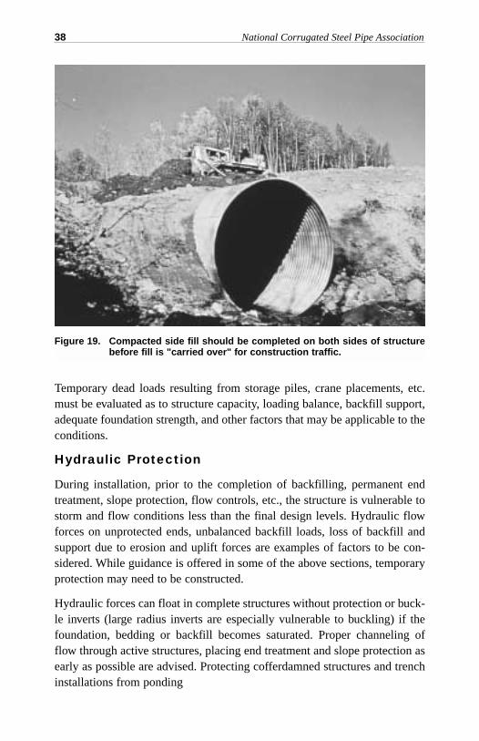
Figure 19. Compacted side fill should be completed on both sides of structurebefore fill is "carried over" for construction traffic.
CSP Installation Manual 39
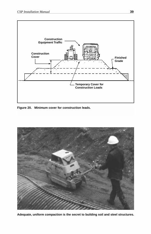
Figure 20. Minimum cover for construction leads.
ConstructionEquipment Traffic
ConstructionCover
Temporary Cover forConstruction Loads
FinishedGrade
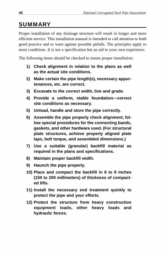
Adequate, uniform compaction is the secret to building soil and steel structures.
SUMMARYProper installation of any drainage structure will result in longer and moreefficient service. This installation manual is intended to call attention to bothgood practice and to warn against possible pitfalls. The principles apply tomost conditions. It is not a specification but an aid to your own experience.
The following items should be checked to insure proper installation:
1) Check alignment in relation to the plans as wellas the actual site conditions.
2) Make certain the pipe length(s), necessary appur-tenances, etc. are correct.
3) Excavate to the correct width, line and grade.
4) Provide a uniform, stable foundation—correctsite conditions as necessary.
5) Unload, handle and store the pipe correctly.
6) Assemble the pipe properly check alignment, fol-low special procedures for the connecting bands,gaskets, and other hardware used. (For structuralplate structures, achieve properly aligned platelaps, bolt torque, and assembled dimensions.)
7) Use a suitable (granular) backfill material asrequired in the plans and specifications.
8) Maintain proper backfill width.
9) Haunch the pipe properly.
10) Place and compact the backfill in 6 to 8 inches(150 to 200 millimeters) of thickness of compact-ed lifts.
11) Install the necessary end treatment quickly toprotect the pipe and your efforts.
12) Protect the structure from heavy constructionequipment loads, other heavy loads andhydraulic forces.
40 National Corrugated Steel Pipe Association
SUBDRAINAGEUnderdrain Pipe
Underdrains, to remove ground water, must be properly installed to givelong, satisfactory service. With perforated steel underdrain pipe, correctinstallation is fast and easy.
Flow Line
The flow line should be placed below water-bearing strata for most effectivedrainage. However, if the strata is too deep to permit draining to a naturaloutlet, the pipe can be placed within the water-bearing material if this wouldpermit natural drainage or a sump pump may be used. This does not providecomplete drainage but will lower the natural water table to a desirable level.Outlets should be free and not subject to flooding or restriction by freezingor debris and protected against damage by maintenance equipment.
Where possible, it is desirable to use a 0.2 percent minimum slope for allsubdrainage lines.
Preparing the Foundation
Underdrain pipe should be laid on a stable foundation. If the bottom of thetrench can be set below the water-bearing strata and the pipe placed in animpervious layer, the foundation will generally be stable. But if the pipe mustbe located in water-bearing strata, it may be necessary to stabilize the bottomof the trench by placing granular material under the pipe. However, corru-gated steel underdrains will hold alignment on soft foundations much betterthan rigid or plastic pipes. Steel pipe is supplied in much longer lengths andthus diminishes the hazards of disjointing, settlement, and loss of alignment.
Assembly of Underdrain Pipe
Assembly or installation of a subdrainage system is usually started at thedownstream or outlet end to allow ground water to drain out of the trench,keeping it reasonably dry during construction.
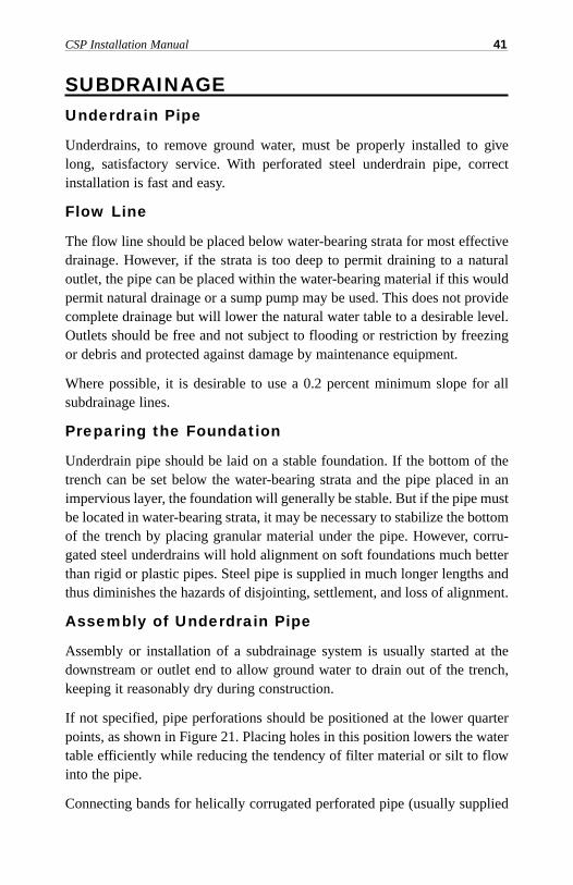
If not specified, pipe perforations should be positioned at the lower quarterpoints, as shown in Figure 21. Placing holes in this position lowers the watertable efficiently while reducing the tendency of filter material or silt to flowinto the pipe.
Connecting bands for helically corrugated perforated pipe (usually supplied
CSP Installation Manual 41
for small diameter drains) may be in two pieces with matching corrugationsto fit this helically corrugated steel pipe or sleeve bands.
Proper Placement of Underdrain
Subdrain material must permit ready flow of water while acting as a filter tokeep fine soil from entering and clogging the subdrain system. Proper grad-ing will help prevent backfill from being carried into the pipe.
Many bank-run sands and concrete sand will make a satisfactory backfill forperforated steel underdrains. Also, material having not more than 10% of itsweight in particles larger than 3/8-inch (9.5 millimeter) will also make a sat-isfactory backfill.
This backfill material should be placed for a width of at least 6 inches (150millimeters) on each side of the pipe and for the depth over the pipe neces-sary to intercept all possible water-bearing strata. Above this area the trenchcould be capped with other normal types of backfill material.
To control settlement, subdrain backfill should be placed in layers and wellcompacted. A geotextile may be used to prevent infiltration of fines, particu-larly at the joint.
42 National Corrugated Steel Pipe Association
Figure 21. Correct placement of perforated steel underdrains.
Locate perforations atlower quarter points
CSP Installation Manual 43
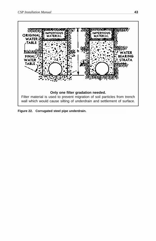
Figure 22. Corrugated steel pipe underdrain.
Only one filter gradation needed.Filter material is used to prevent migration of soil particles from trenchwall which would cause silting of underdrain and settlement of surface.
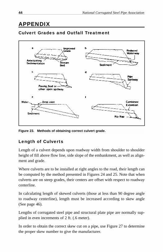
APPENDIXCulvert Grades and Outfall Treatment
Length of Culverts
Length of a culvert depends upon roadway width from shoulder to shoulderheight of fill above flow line, side slope of the embankment, as well as align-ment and grade.
Where culverts are to be installed at right angles to the road, their length canbe computed by the method presented in Figures 24 and 25. Note that whenculverts are on steep grades, their centers are offset with respect to roadwaycenterline.
In calculating length of skewed culverts (those at less than 90 degree angleto roadway centerline), length must be increased according to skew angle(See page 46).
Lengths of corrugated steel pipe and structural plate pipe are normally sup-plied in even increments of 2 ft. (.6 meter).
In order to obtain the correct skew cut on a pipe, use Figure 27 to determinethe proper skew number to give the manufacturer.
44 National Corrugated Steel Pipe Association
Figure 23. Methods of obtaining correct culvert grade.
CSP Installation Manual 45
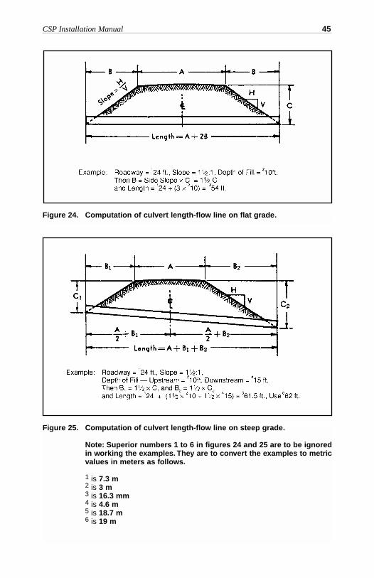
Figure 25. Computation of culvert length-flow line on steep grade.
Note: Superior numbers 1 to 6 in figures 24 and 25 are to be ignoredin working the examples. They are to convert the examples to metricvalues in meters as follows.
1 is 7.3 m 2 is 3 m3 is 16.3 mm 4 is 4.6 m5 is 18.7 m6 is 19 m
Figure 24. Computation of culvert length-flow line on flat grade.
46 National Corrugated Steel Pipe Association
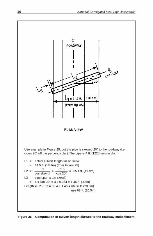
Figure 26. Computation of culvert length skewed to the roadway embankment.
Use example in Figure 25, but the pipe is skewed 20° to the roadway (i.e.,cross 20° off the perpendicular). The pipe is 4 ft. (1220 mm) in dia.
L1 = actual culvert length for no skew= 61.5 ft. (18.7m) (from Figure 25)
L1 61.5L2 = _________ = _______ = 65.4 ft. (19.9m)
cos skew∠ cos 20°L3 = pipe span x tan skew∠
= 4 x Tan 20° = 4 x 0.364 = 1.46 ft. (.45m)Length = L2 + L3 = 65.4 + 1.46 = 66.86 ft. (20.3m)
use 68 ft. (20.5m)
CSP Installation Manual 47
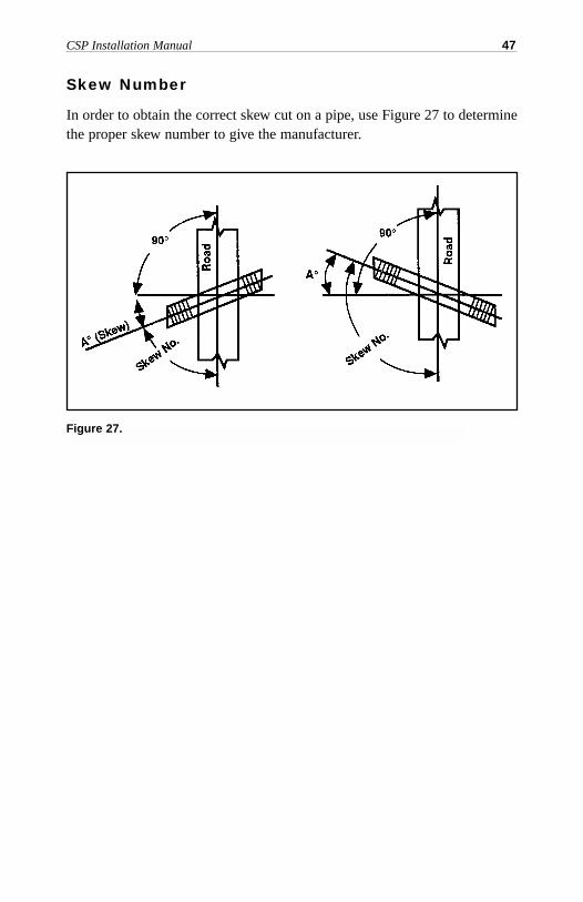
Skew Number
In order to obtain the correct skew cut on a pipe, use Figure 27 to determinethe proper skew number to give the manufacturer.
Figure 27.

48 National Corrugated Steel Pipe Association
NOTES
NATIONAL CORRUGATED STEEL PIPE ASSOCIATION
1255 Twenty-Third Street, NW, Suite 200Washington, DC 20037-1174
Phone: 202/452-1700 • Fax: 202/833-3636E-mail: [email protected] • Web: www.ncspa.org