ncrp 33: medical x-ray and gamma-ray protection for energies
TRANSCRIPT

By Authority OfTHE UNITED STATES OF AMERICA
Legally Binding Document
By the Authority Vested By Part 5 of the United States Code § 552(a) and Part 1 of the Code of Regulations § 51 the attached document has been duly INCORPORATED BY REFERENCE and shall be considered legally binding upon all citizens and residents of the United States of America. HEED THIS NOTICE: Criminal penalties may apply for noncompliance.
Official Incorporator:THE EXECUTIVE DIRECTOROFFICE OF THE FEDERAL REGISTERWASHINGTON, D.C.
Document Name:
CFR Section(s):
Standards Body:
e


NCRP REPORT No. 33
MEDICAL X-RAY AND GAMMA-RAY PROTECTION FOR ENERGIES UP TO 10 MeV
Equipment Design and Use
Rf)~ommedations of the NATIONAL COUNCIL ON RADIATION PROTECTION AND MEASUREMENTS
Issued February 1, 1968 First Reprinting June 1,1971 Second Reprinting March 1, 1973
National Council on Radiation Protection and Measurements 7910 WOODMONT AVENUE / WASHINGTON, D.C. 20014
t I'
'I I

t"!k
Preface
This report of the National Council on Radiation Protection and Measurements, successor to the National Committee on Radiation Protection and Measurements, is concerned with radiation protection in connection with the medical use of x and gamma rays having energies up to 10 MeV. It represents in several respects a deviation from previous NCRP practice in dealing with the subject. In the past, the NCRP has treated comprehensively in one report the use of gamma-ray sources (NCRP Report No. 24, National Bureau of Standards Handbook 73) and in another report the use of x-ray sources (NCRP Report No. 26, National Bureau of Standards Handbook 76). Each of these reports dealt with equipment design and use as well as structural shielding. Now, however, the Council believes that a more useful treatment will result from consideration of design and operational problems in one report and structural shielding problems in another. This report is concerned primarily with the design and operational aspects of medical x-ray equipment and gamma-beam therapy equipment. The Council expects to publish soon other reports treating (1) structural shielding aspects of medical x- and gamma-ray installations up to 10 MeV (NCRP Report No. 34), (2) brachytherapy sources, (3) dental x-ray equipment and installations (NCRP Report No. 35), and (4) veterinary x-ray protection.
This report is intended to serve as a guide to good practice in medical radiation protection. While it provides basic standards for use in the preparation of regulatory protection codes, it is not specifically written for literal adoption as legal regulations.
This report contains a number of recommendations concerning the design and performance characteristics of medical radiation producing equipment and the manner in which it is used. The recommendations vary in importance and in applicability; some are particularly important for large busy installations but not for installations with very low work loads; some apply to all equipment of a given kind whereas others need not apply to equipment designed prior to publication of this report. In this regard, it is important to recognize that efficiency
iii
l'i! ii ,:'!;
ii

and safety in the utilization of radiation equipment is influenced critically not only by its design characteristics but also by the manner of its use. For this reason, the Council believes that the risk involved in the judicious use of older equipment failing to meet the revised standards of this report is not necessarily so great as to justify the condemnation of thousands of otherwise satisfactory units.
Initial funds for publication of NCRP reports are being provided by the James Picker Foundation and for this the Council wishes to express its deep appreciation.
The present report was prepared by the Council's Scientific Committee 3 on Medical X- and Gamma-Ray Protection up to 10 MeV (Equipment Design and Use). Serving on the Committee during the preparation of this report were:
Working Group
J. HALE
F •. R. HENDRICKSON
J. S. KROHMER
R. R. NEWELL'"
E. D. TROUT
W. J. TUDDENHAM
E. W. WEBSTER
'" Deceased
R. O. GORSON, (J/w,irman
Advisory Group & Con8ultants
C. B. BRAESTRUP
E. F. FOCHT
J. HArMSON
C. J. KARZMARK
E. R. MILLER
J. M. MOZLEY
R. J. NELSEN
S. W. SMITH
B. P. SONNENBLICK
M. H. WITTENBORG
H. O. WYCKOFF
The Council wishes to express its appreciation to the members of the Committee for the time and effort they devoted to the preparation of this report.
Washington, D.C. January 1, 1968
iv
LAURISTON S. TAYLOR
President, NCRP
Contents
Preface ..
1. Introduction 1.1 Scope .. 1.2 Purpose
2. General Considerations 2.1 Fundamental Objective 2.2 Maximum Permissible Dose Equivalent (MPD) .. 2.3 Exposure of Individuals 2.4 General Guidelines In the Clinical Use of Radiation ..
3. X.ray Equipment 3.1 Fluoroscopic Equipment 3.2 Fixed Radiographic Equipment 3.3 Mobile Radiographic Equipment 3.4 X-ray Therapy Equipment ..
4. Gamma-Beam Therapy Equipment .. 4.1 Gamma-Beam Sealed Sources 4.2 Gamma-Beam Equipment ..
5. Therapy Equipment Calibration Guides S.1 General 5.2 Calibration .. 5.3 Recalibration 5.4 Spot Check Measurement
6. Radiation Protection Surveys 6.1 General Survey Procedures 6.2 Surveys of Radiation Equipment
7. Working Conditions 7.1 General 7.2 Radiation Protection Supervisor 7.3 Personnel Monitoring .. 7.4 Medical Examination .. 7.5 Vacatiolll'J ..
8. References ..
iii
1 1 1
3 3 3 4 5
7 7
12 16 17
22 22 23
27 27 27 28 28
29 29 31
32 32 32 33 34 34
35
APPENDIXA.
APPENDIX B.
APPENDIX C.
Definitions 37
TheNCRP ..
NCRP Reports
Index
Tables 41
Example of Emergency Procedures for Failure of Gamma-Beam Control Mechanism 46
48 52
57
1 ',Ii" I,
il
( I
, : I

1. Introduction
1.1 Scope
This report, which supersedes parts of NCRP Reports 24 and 26 (NBS Handbooks 73 and 76) [1, 2]1, is concerned with protection against radiation emitted by medical x-ray equipment operating at energies up to 10 MeV and medical gamma-beam therapy equipment. It presents recommendations pertaining to equipment design, use, and operating conditions, and to radiation protection surveys and personnel monitoring. To be covered in separate reports are recommendations concerning structural shielding design and recommendations concerning dental x-ray and veterinary x-ray protection and brachytherapy sources.
This report includes sections for the specific guidance of (1) the physician and his associates, (2) the equipment designer and manufacturer, (3) the radiological physicist concerned with calibration procedures, equipment performance, and protection surveys and, (4) the radiological health inspector concerned with equipment inspection and survey measurements.
1.2 Purpose
The purpose of this report is to indicate the protection required in various circumstances and to describe one or more methods by which the required protection may be achieved. The recommendations are not meant to preclude alternative methods of achieving the radiation protection objectives. Since it is recognized that blind adherence to rules cannot substitute for the exerci_se of sound judgment, the recommendations of this report may well be modified in unusual circumstances upon the professional advice of experts with recognized competence in medical radiation protection. In an effort to ensure informed and judicious application of these recommendations, explanatory paragraphs designated Comment have been included, where appropriate, throughout this report.
This report contains design recommendations, some of which are new and some of which represent modifications of previous recommenda-
1 Figures in brackets indicate the literature references lit;lted in Section 8.
1
--, !'
,I
I'

2 / INTRODUCTION
tions. Such new and modified recommendations are not intended to apply to equipment designed before the publication of this report. In general, such equipment may be regarded as acceptable from the standpoint of radiation safety if it meets the recommendations of NCRP Reports 24 and 26. In CaBes of doubt, however, qualified experts should be consulted about the appropriateness and the feasibility of modifying existing equipment to conform with the new or revised recommendations in question ..
Terms used in this report are defined in Appendix A. Since, however, recommendations throughout this report are expressed in terms of "shall" and "should," these terms are defined here.
(1) Shall indicates a recommendation that is necessary or essential to meet the currently accepted standards of protection.
(2) Should, is recommended, is advisable, indicates an advisory l,"ecommendation that is to be applied when practicable.

2. General Considerations
2.1 Fundamental Objective
The fundamental objective of the medical use of radiation is to obtain optimum diagnostic information or therapeutic effect with minimum exposure of the patient, the radiological personnel concerned, and the general public. To achieve this objective in specific situations requires knowledge of the many technical factors and clinical considerations involved and an understanding of their relative importance.
The exposure of individuals can be greatly reduced by the correct application of technical methods. For patient exposure, however, the need for radiologic examination or treatment, the procedures to be employed, and the frequency of their repetition, can be determined only by the professional judgments of physicians and of other practitioners of the healing arts. Such judgment is developed through sound basic training, experience, and continued education and is difficult to control by rules and regulations. Therefore, this report is devoted principally to the technical aspects of minimizing unproductive radiation exposure of human beings.
2.2 Maximum Permissible Dose Equivalent (MPD)
Results of studies on the somatic and genetic effects of radiation are reviewed in other NCRP reports. These results have been utilized in developing recommendations for Maximum Permissible Doses by the National Council on Radiation Protection and Measurements (See NCRP Report No. 17) [3] and by the International Commission on Radiological Protection. The primary objective in establishing M'PD values for occupational exposure is to keep the exposure of the radiation worker well below a level at which adverse effects are likely to be observed during his lifetime. Another objective is to minimize the incidence of genetic effects for the population as a whole. The occupational MPD for persons working in controlled areas is summarized
3
I I Iii
"Ii :1 Ii
I I
1

4 / 2. GENERAL CONSIDERATIONS
in Table I, Appendix B. These values do not include any dose received by an individual as a patient or the dose from natural background radiation.
It must be emphasized that the risk to individuals exposed to the MPD is considered ,to be very small; however, risk increases gradually with the dose received. For this reason, it is desirable to keep radiation exposures as low as is practical with due consideration to medical objectives, feasibility, and efficiency of operation. For the same reason, small transient deviations in the exposure of an individual above the prescribed levels are unimportant except as an indication of inadequate protection practices. For administrative purposes, such a deviation should be regarded simply as a "technical overexposure" as distinct from "overexposure" since the term "overexposure" may have the connotation of injury.
2.3 Exposure of Individuals
2.3.1 Exposure of Persons Other Than the Patient. Reduction of radiation exposure to an individual from external sources of radiation may be achieved by anyone or any combination of the following measures: (a) increasing the distance of the individual from the source, (b) reducing the duration of exposure and (c) using protective barriers between the individual and the source. For medical x-ray and gamma-ray equipment, shielding and distance a~e the factors most readily controlled. Protective shielding includes that incorporated into equipment; it may also consist of mobile or temporary devices used as the occasion demands, such as movable screens, or lead impregnated aprons and gloves; or it may comprise permanent protective barriers and structural shielding such as walls containing lead, concrete, or other materials in thicknesses sufficient to provide the reqUired degree of attenuation. Structural shielding is an important part of installation planning and is covered in the forthcoming NCRP Report No. 34. 2.3.2 Exposure of the Patient. Techniques employed in radiography and radiation therapy should be those which achieve the desired objectives with minimum dose to the patient. Conflicting factors are often involved, depending upon the type of radiologic examination or condition to be treated. In such instances, compromise must be based on professional experience and judgment. For example, use of higher x-ray tube voltages and greater thicknesses of added filtration in radiography generally result in smaller doses to the patient for a given optical
~ I

2.4 GUIDELINES IN CLINICAL USE / 5
density of the x-ray film. Under these conditions, however, the contrast of the radiographic image is reduced, resulting in a loss of information which may be critical in certain types of examination. As ano.ther example, the use of high speed films and intensifying screens reduces patient exposure, but an associated decrease in image definition may also reduce the value of the examination.
2.4 General Guidelines in the Clinical Use of Radiation
As a general principle, the exposure to the patient shall be kept to the practical minimum consistent with clinical objectives. To this end, the following recommendations are presented for the guidance of physicians and others resp·onsible for the exposure of patients [4]. 2.4.1 The useful beam should be limited to the smallest area practicable and consistent with the objectives of the radiological examination or treatment. 2.4.2 The voltage, filtration and source-skin distance (SSD) employed in medical radiological examinations should be as great as is practical and consistent with the diagnostic objectives of the study [5]. (For dental x-ray examinations, see NCRP Report No. 35). 2.4.3 Protection of the embryo or fetus during radiological examination or treatment of women known to be pregnant should be given special consideration.
Comment: Ideally, abdominal radiological examination of a woman of childbearing age should be performed during the first few (approximately 10) days following the onset of menses to minimize the possibility of irradiation of an embryo. In practice, medical needs should be the primary factors in deciding the timing of the examination.
2.4.4 Suitable prDtective devices to. shield the gonads Df patients who. are pDtentially prDcreative should be used when the examinatiDn or methDd Df treatment may include the gDnads in the useful beam, unless such devices interfere with the cDnditiDns or objectives of the examination or treatment. 2.4.5 Fluoroscopy should not be used as a substitute for radiography, but should be reserved for the study of dynamics Dr spatial relationships Dr for guidance in spot-film recording of critical details. 2.4.6 X-ray films, intensifying screens, and other image recording devices, should be as sensitive as is cDnsistent with the requirements of the examination.

6 / I 2. GENERAL CONSIDERATIONS
2.4.7 Film processing materials and techniques should be those recommended by ,the x-ray film manufacturer or those otherwise tested to ensure maximum information content of the developed x-ray film and, where practical, quality control methods should be employed to ensure optimum results.

3. X-ray Equipment
3.1 Fluoroscopic Equipment2
3.1.1 Design Recommendations.
(a) A diagnostic-type protective tube housing shall be used. (See definition in Appendix A) [6].
(b) The source-panel or source-tabletop distance shall be at least 12 inches (30 cm) and should not be less than 15 inches (38 cm). The source-skin distance of image intensifier equipment should not be less than 15 inches (38 cm).
Comment: The greater the source-tabletop distance, the lower is the entrance dose (and to a lesser extent, the integral dose) for a given screen luminance. Image unsharpness and image magnification also are reduced. However, other considerations place a practical upper limit on the source-tabletop distance. The heating load on the x-ray tube increases rapidly with distance because greater tube current is required to maintain constant screen luminance. For the same reason, it may be necessary to increase spot-film exposure time resulting in greater motion unsharpness. From the standpoint of radiation safety, it appears that the source-tabletop distance is not critical within rather broad limits. For conventional fluoroscopes, a distance of 15-18 inches seems to be a reasonable compromise between the conflicting factors involved [7].
(c) The total filtration permanently in the useful beam shall be at least 2.5 millimeters aluminum equivalent. When the tabletop or panel surface is interposed between the source and the patient, its aluminum equivalent may be included as part of the total filtration. (See comment under 3.2.2 (a).)
(d) The equipment shall be so constructed that, under conditions of normal use, the entire cross section of the useful beam is attenuated by a primary protective barrier, permanently incorporated into the equipment. The exposure shall automatically terminate when the barrier is removed from the useful beam.
• Including image intensified fluoroscopic equipment.
7
~,..
I

8 / 3. X-RAY EQUIPMENT
(1) The lead equivalent of the barrier of conventional fluoroscopes shall be at least 1.5 millimeters for equipment capable of operating up to 100 kVp, at least 1.8 millimeters for equipment whose maximum operating potential is greater than 100 kVp and less than 125 kVp, and at least 2.0 millimeters for equipment whose maximum operating potential is 125 kVp or greater [8]. Special attention shall be paid to the shielding of image intensifiers so that neither the useful beam nor the scattered radiation from the intensifier itself or from the patient will produce significant radiation exposure to the operator or other personnel.
(2) A collimator shall be provided to restrict the size of the useful beam to less than the area of the barrier. The x-ray tube and collimating system shall be linked with the fluorescent screen assembly so that the useful beam at the fluorescent screen is confined within the barrier irrespective of the panel-screen distance. (See 3.1.2 (d).) For image intensifiers, the useful beam should be centered on the input phosphor and during fluoroscopy or cine-recording, it should not exceed the diameter of the input phosphor. (Ideally, for spot film radiography with image intensifier equipment, the shutters should automatically open to the required field size before each exposure) .
(3) Collimators, adjustable diaphragms and shutters shall provide the same degree of attenuation as is required of the tube housing. (e) The fluoroscopic exposure switch shall be of the dead-man type.
(See definition in Appendix A) . (f) Provision shall be made to intercept the scattered x rays from
the undersurface of the tabletop and other structures under the table. In most cases, this may be accomplished either by a cone extending from the tube housing to the tabletop or by a shield around the fluoro-scopE! understructure, or both. The cone shall provide the same degree.1 of attenuation as is required of the tube housing, with the incident angle of the useful beam taken into consideration.
(g) A shielding device of at least 0.25 mm lead equivalent for covering the Bucky slot during fluoroscopy should be provided.
(h) A shield of at least 0.25 mm lead equivalent, such as overlapping protective drapes Or hinged or sliding panels, should be provided to intercept scattered radiation which would otherwise reach the fluoroscopist and others near the machine.
(i) A cumulative timing device, activated by the fluoroscope exposure switch, shall be provided. It shall indicate the passage of a predetermined period of irradiation either by an audible signal or by

3.1 FLUOROSCOPIC EQUIPMENT / 9
temporary interruption of the irradiation when the increment of exposure time exceeds a predetermined limit not exceeding five minutes.
Comment: While the timer does not ensure safe operation it is of value as a training device for physicians learning the techniques of fluoroscopy, and for the experienced fluoroscopist as a means for emphasizing the passage of time. The design should be such that the timer reset mechanism does not create a nuisance for the physician.
(j) Devices which indicate the x-ray tube potential and current shall be provided. On image intensified fluoroscopic equipment, such devices should be located in such a manner that the operator may monitor the tube potential and current during fluoroscopy. (See comment under 3.1.3 (b) .)
(k) Image intensification shall always be provided on mobile fluoroscopic equipment. It shall be impossible to operate mobile fluoroscopic equipment unless the useful beam is intercepted by the image intensifier. Inherent provisions shall be made so that the machine is not operated at source-skin distance of less than 12 inches (30 cm).
(1) Equipment to be operated in areas where explosive gases may be used should have the approval of Underwriters Laboratory for such use.s 3.1.2 Performance Standards: This section is primarily for the guidance of those concerned with evaluating the radiation safety characteristics of fluoroscopes. In general, equipment built according to the design recommendations of section 3.1.1 will meet the standards of performance outlined below.
(a) When the fluoroscope is operated at 80 kVp, the exposure rate measured in air at the position where the beam enters the patient shall not exceed 3.2 RimA-min and should not exceed 2.1 RimA-min. For other fluoroscopic ,tube potentials, the exposure per unit charge shall not exceed the values marked with an asterisk (*) in Table 2, Appendix B and should not exceed the values marked with a dagger sign (tr (See also 3.1.3(a) and (b).)
Comment: The tabletop exposure rate is probably the most important single index of equipment performance. If the measured values exceed the appropriate values, marked with an asterisk (*) in Table 2, the reasons should be investigated. Exposure rate measurements should also be made under the operating conditions normally used by the physician when such information is known.
8 Information may be obtained from Underwriters Laboratory, 207 East Ohio Street, Chicago, Illinois 60611.
I II
ii'

10 / 3. X-RAY EQUIPMENT
(See 3.1.3 (a) and (b». With modern equipment, most fluoroscopy can be carried out with exposure rates of less than 5 R/min. If a fluoroscope meets the performance standards of this section but the fluoroscopist finds it necessary to operate the equipment routinely at exposure rates in excess of 5 R/min, it is advisable to check the efficiency of the fluorescent screen by comparing it with a new screen. It may .be necessary to replace the screen, particularly in older equipment.
(b) If the amount of filtration in the fluoroscope is unknown, .the half value layer of the useful beam should be measured. Recommendation 3.1.1 (c) may be assumed to have been met if the half-value layer is not less than 2.4 mm of aluminum when the fluoroscopic tube is operated at 80 kVp. For other tube potentials, the measured half-value layers should not be less than the corresponding values specified by a dagger sign (t) in Table 3, Appendix B. (See Comment under 3.2.2 (a).)
(c) With the fluorescent screen 14 inches (35 cm) from the panel or tabletop, the exposure rate 2 inches (5 cm) beyond the viewing surface of the screen shall not exceed 30 mR/h for each R per minute at the tabletop with the screen in the useful beam without a patient and with the fluoroscope operating at the highest potential employed. (Note: When the operating conditions are known, Table 4 in Appendix B may be used as a guide for determining the expected exposure rate 2 inches (5 cm) beyond the viewing surface).
(d) When the adjustable diaphragm is opened to its fullest extent, an unilluminated margin shall exist at all edges of the fluorescent screen when the screen is 14 inches (35 cm) from the panel surface or tabletop, or at the fixed screen position in equipment such as an orthodiascope. In equipment used solely for image intensified fluoroscopy, the shutter should restrict the useful beam to the diameter of the input phosphor.
3.1.3 Guidelines for the Fluoroscopist.
(a) The exposure rate used in fluoroscopy should be as low as is consistent with the fluoroscopic requirements and shall not normally exceed 10 R/min (measured in air) at the position where the beam enters the patient. This recommendation applies .to the use of image intensifier equipment (with or without television cameras) as well as conventional (direct viewing) fluoroscopes. (See Comment under 3.1.2 (a) .)
(b) The fluoroscopist should know the radiation characteristics of
_ . ..,..

3.1 FLUOROSCOPIC EQUIPMENT / 11
his equipment. Therefore periodic measurements of table top or patient exposure rate shall be made. Patient exposure measurements are especially necessary on apparatus employing image intensifiers in which the intensifier brightness is automatically controlled and the x-ray factors in use are not readily ascertained. Such measurementf> necessitate the use of a phantom in the fluoroscopic beam.
Comment: Image intensifiers may significantly reduce both observation time and' exposure rate when properly used, but do not inherently accomplish this reduction. In equipment with automatic brightness control, the tube potential and current may rise to high values without knowledge of the operator, particularly if the gain of the intensifier is diminished. It is important, therefore, for the operator to monitor tube current and potential on such equipment.
(c) The smallest practical field sizes and shortest exposure times should be employed. The possibilities of reducing dose by techniques utilizing high tube potential and low current should be considered.
(d) Fluoroscopy should not be used as a substitute for radiography but should be reserved for the study of dynamics or spatial relationships or for guidance in spot-film recording of critical details.
(e) Medical fluoroscopy should be performed only by or under the immediate supervision of physicians' properly trained in fluoroscopic procedures.
(f) The fluoroscopist's eyes should be sufficiently dark-adapted for the visual task required before commencing fluoroscopy. Under no circumstances should he attempt to compensate for inadequate adaptation by increasing the exposure factors employed or by prolonging the fluoroscopic examination.
Comment: The perception of detail under conditions of scotopic vision requires retinal adaptation. The adaptation time necessary for the competent performance of a specific visual task depends upon the nature of the task itself, the pre-exposure luminance level and color, the conditions of adaptation, and a number of other physiologic factors. While wearing red goggles for 10 minutes will usually satisfy adaptation requirements in fluoroscopy, no specific adaptation period can be recommended for all situations [9]. Dark adaptation normally is not necessary when using image intensifiers.
(g) Extraneous light that interferes with the fluoroscopic examination shall be eliminated.
(h) Special precautions, consistent with clinical needs, should be taken to minimize exposure of the gonads of potentially procreative pa-

12 I 3. X-RAY EQUIPMENT
tients and exposure of the embryo or fetus in patients known to be or suspected of being pregnant. (See 2.4.3 and 2.4.4) .
(i) In cineradiography, special care should be taken to limit patient exposure when, as is of.ten the case, tube currents and potentials employed are higher than those normally used in fluoroscopy. The exposure rates to which patients are normally subjected shall be determined periodically.
(j) Protective aprons of at least 0.25 mm lead equivalent should be worn in the fluoroscopy room by each person (except the patient) whose trunk is exposed to radiation fields of 5 mR/h or more.
Comment: A busy fluoroscopist is unlikely to operate a fluoroscope more than five hours per week. Therefore, he would be unlikely to receive more than ~ the maximum permissible dose to the trunk of the body if the scattered radiation level is less than 5 mR per hour. However, other sources of exposure also should be taken into account when deciding whether a protective apron is to be worn.
(k) The hand of the fluoroscopist should not be placed in the useful beam unless the beam is attenuated by the patient and a protective glove of at least 0.25 mm lead equivalent.
(1) Only persons whose presence is needed should be in the fluoroscopy room during x-ray exposures.
3.2 Fixed Radiographic Equipment
3.2.1 Design Recommendations.
(a) A diagnostic-type protective tube housing shall be used. (See definition in Appendix A) [6].
(b) Suitable devices (diaphragms, cones, adjustable collimators), capable of restricting the useful beam to the area of clinical interest shall be provided to define the beam and shall provide the same degree of attenuation as that required of the tube housing. Such devices shall be calibrated in terms of the size of the projected useful beam at specified source-film distances. (See 3.2.2 (b).) For chest photofluorographic equipment, the collimator shall restrict the beam to dimensions no greater than those of the fluorographic screen.
(c) Radiographic equipment, particularly multipurpose machines, should be equipped with adjustable collimators containing light 10-

3.2 FIXED RADIOGRAPHIC EQUIPMENT / 13
calizers that define the entire field. Rectangular collimators are usually preferable. Means should be provided to produce a visible indication of adequate collimation and alignment on the developed x-ray film. The field size indication on adjustable collimators shall be accurate to within one inch for a source-film distance of 72 inches. The light field shall be aligned with the x-ray field with the same degree of accuracy.
(d) The aluminum equivalent of the total filtration in the useful beam shall be not)ess than that shown in the following table: (See also Section 3.2.2(a). For dental radiography, see forthcoming NCRP Report No. 35.)
Operating kVp
Below 50 kVp 50-70 kVp Above 70 kVp
Minimum Total Filter (Inherent plus added)
0.5 mm aluminum 1. 5 mm aluminum 2.5 mm aluminum
(e) A device shall be provided which terminates the exposure at a preset time interval or exposure. The operator should be able to terminate the exposure at any time.
(f) The exposure switch, except for those used in conjunction with "spot-film" devices in fluoroscopy, shall be so arranged that it cannot be conveniently operated outside a shielded area.
(g) The control panel shall include a device (usually a milliammeter) to give positive indication of the production of x rays whenever the x-ray tube is energized.
(h) The control panel shall include devices (labelled control settings and/or meters) indicating the physical factors (such as kVp, mA, exposure time or whether timing is automatic) used for the exposure.
(i) Machines equipped with beryllium window x-ray tubes shall contain keyed filter interlock switches in the tube housing and suitable indication on the control panel of the added filter in the useful beam if the total filtration permanently in the useful beam is less than 0.5 mm aluminum equivalent. The total filtration permanently in the useful beam shall be clearly indicated on the tube housing.
Com,rnent: Beryllium window x-ray tubes with no added filtration. emit low energy x rays at very high exposure rates. It is particularly important, therefore, that the operator be able to tell by a glance at the control panel how much added filter, if any, is present.
(j) Beryllium window x-ray tubes should not be used on multipurpose radiographic equipment.
-..,
-i
,I
:1

14 / 3. X-RAY EQUIPMENT
(k) The aluminum equivalent of the tabletop when a cassette tray is used under the table top, or the aluminum equivalent of the front panel of the vertical cassette holder, shall not be more than 1 mm at 100kVp.
(1) Equipment to be operated in areas where explosive gases may be used should have the approval of Underwriters Laboratory for such use.s
3.2.2 Performance Standards.
(a) If the filter in the machine is not accessible for examination and the total filtration is unknown, the half-value layer of the useful beam should be measured. Recommendation 3.2.1 (d) may be assumed to have been met if the half-value layer is not less than 0.6 mm aluminum when the x-ray tube is operated at 49 kVp, or not less than 1.6 millimeters aluminum at 70 k Vp, or not less than 2.6 millimeters aluminum at 90 kVp. For other tube potentials, the measured half-value layers should not be less than the corresponding values specified by ail asterisk (*) in Table 3, Appendix B. (For dental radiography, see forthcoming NCRP Report No. 35.)
Comment: The purpose of the filter is to absorb preferentially the lower energy (longer wavelength) portions of the x-ray spectrum which would otherwise be absorbed by the patient without significantly contributing to the information reaching the film. In general, the greater the amount of filtration, the greater the average energy of the x-ray beam, and the smaller the dose to the patient for a given exposure to the x-ray film. However, depending on kVp, the rate of dose reduction with increasing filtration diminishes rapidly and practical considerations place an upper limit on the amount of filtration that is reasonable in a given type of radiological examination. In practice, small changes in filter thickness are unimportant and for the great majority of x-ray examinations, one filter will suffice. Since relatively few examinations (such as mammography) are carried out below 50 kVp, most radiographic equipment should have 2 or more millimeters of added aluminum filtration securely fixed in the tube housing.
(b) The size of the x-ray beam projected by fixed aperture cones and collimators (except those used for stereoradiography) should not exceed the dimensions of the x-ray film by more than 2 inches for a source-film distance (SFD) of 72 inches or 1 inch for a source-film distance of 36 inches as illustrated in Figure 1.
(c) In general, modern diagnostic tube housings incorporate suf-
I Information may be obtained from Underwriters Laboratory, 207 East Ohio Street, Chicago, Illinoil! 60611.

32 FIXED RADIOGRAPHIC EQUIPMENT / 15
Maximum field size for Maximum field size for
rec~tangUlar ~~~ _____ ~ ___ ;:-___ ~_~ _________ ~i~c~~r cone
X-ray film
I ..,........ -........... I ., I //; ' ....
! ///. /'\\ I I \ I I \ I 1< ,
I f + \ Y Y+2
I \ / 1 I \ / I
\ / I " / I
"-. ",/ I I -.~ ,. I L ___________ :~~~ ___ ~~~ ___________ ~
1""' .. 1------ X inches -----'--,..----., .. ~I
1""1 .. 1------- X + 2 inches ---'-"--'--'-~-I"--ll
Fig. 1. Maximum beam size at 72 inch SFD.
ficient attenuating material to limit the leakage radiation to that permitted in the definition of a diagnostic-type protective tube housing (See Appendix A) and it usually is unnecessary to perform leakage tests in the field on modern x-ray machines. When in doubt, however, the following method for testing "for leakage radia.tion is recommended: With the window of the housing blocked with at least 10 HVL of absorbing material (e.g., lead), the leakage radiation should be measured with the x-ray tube operating at its maximum voltage and a.t its maximum current for continuous operation at that voltage. When this method of testing is not prac.tical, the test may be made at higher current, provided that careful consideration is given to the limitation of operating time imposed by the heat capacity of the tube or target as determined from the manufacturer's tube rating and cooling charts. Small areas of reduced protection are acceptable in evaluating the maximum exposure rate provided the average reading over 100 square centimeters at one meter distance does not exceed 100 mR per hour (normalized to maximum current for continuous operation) .
3.2.3 Guidelines for the User. (See also Section 2.4.)
(a) Particular care should be taken to limit the useful bea'm to the smallest area consistent with clinical requirements and to align accurately the x-ray beam with the patient and film. (See also 3.2.2 (b).)

16 / 3. X-RAY EQUIPMENT
(b) Gonadal shielding should be used for the patient when appropriate, (see 2.4.4) but never as a substitute for adequate beam collimation and alignment.
(c) When a patient must be held in position for radiography, mechanical supporting or restraining devices should be used. If the patient must be held by an individual, that individual shall be protected with appropriate shielding devices such as protective gloves and apron and he should be 'so positioned that no part of his body will be struck by the useful beam and that his body is as far as possible from the edge of the useful beam.
(d) Only persons whose presence is necessary shall be in the radiographic room during exposure. All such persons shall be protected.
(e) The radiographer shall stand behind the barrier provided for his protection during radiographic exposures.
(f) Special care shall be taken to ensure adequate filtration in multi-purpose machines.
Comment: For soft tissue radiography such as mammography, operating potentials considerably below 50 kVp may be required. In performing such examinations on multipurpose machines, it is usually necessary to reduce the amount of filtration. It is important, however, that the appropriate filter be replaced before proceeding with exposures requiring normal filtration.
(g) Particular care shall be taken to ensure adequate filtration in any machine equipped with a beryllium window tube. Appropriate added filter is required to provide the filtration values recommended in section 3.2.1 (d). (See also 3.2.1 (i) and (j).)
3.3 Mobile Radiographic Equipment
3.3.1 Des1:gn Recommendations.
(a) Recommendations given in section 3.2.1 for fixed radiographic equipment are applicable to mobile equipment except for paragraphs (f) and (k).
(b) Inherent provisions shall be made so that the equipment is not operated at source-skin distances of less than 12 inches (30 cm).
(c) The exposure switch shall be so arranged that the operator can stand at least six feet from the patient, the x-ray tube, and the useful beam.
(d) If a mobile x-ray machine is used routinely in one location, it
.. j I
i I

3.4 X-RAY THERAPY EQUIPMENT / 17
should be considered a fixed installation. The shielding requirements for fixed installations apply (see forthcoming NCRP Report No. 34).
3.3.2 Performance Standards.
The performance standards of section 3.2.2 for fixed radiographic equipment are applicable to mobile equipment.
3.3.3 Guidelines for the User.
(a) Recommendations of section 3.2.3 for fixed radiographic units apply also to mobile equipment except for paragraphs (d) and (e).
(b) The operator should use the maximum source-skin distance (SSD) consistent with the conditions of the radiographic examination. Distances less than 12 inches (30 cm) shall not be used. Distances less than 15 inches (38 cm) should not be used.
(c) Mobile x-ray equipment shall not be used for fluoroscopy, unless it meets the requirements for mobile fluoroscopes (see 3.1.1 (k).)
(d) The operator should stand as far as possible from the patient, the tube, and the useful beam. He should wear a protective apron or stand behind a suitable shield.
(e) Mobile equipment should be used only for examinations where it is impractical to transfer patients to permanent radiographic installations.
(f) The responsible medical supervisor should assure himself that operators of mobile equipment understand the proper use and limitations of the equipment so as to avoid needless exposure of the patient, and other persons in the vicinity.
3.4 X-ray Therapy Equipment
3.4.1 Design Recommendations.
(a) A therapeutic-type protective tube housing shall be used. (See definition in Appendix A). Contact therapy machines shall meet the additional requirement that the leakage radiation at 2 inches (5 cm) from the surface of the housing not exceed 0.1 R/h.
(b) Permanent diaphragms or cones used for collimating the useful beam shall afford the same degree of attenuation as is required of the housing.

18 / 3. X-RAY EQUIPMENT
(c) Adjustable or removable beam-defining diaphragms or CDnes shall transmit not mDre than 5 percent Df the useful beam as determined at the maximum tube pDtential and with maximum treatment filter.
(d) The filter system shall be so. arranged as to. minimize the pDssibility Df errDr in filter selectiDn and alignment. The filter slDt shall be so. cDnstructed that the radiatiDn escaping thrDugh it dDes nDt prDduce an expDsure exceeding 1 Rlh at Dne meter, Dr if the patient is likely to. be expDsed to. radiatiDn escaping frDm the slDt, 30 Rlh at 2 inches (5 cm) frDm the external Dpening. Each remDvable filter shall be marked with its thickness and material.
(e) A filter indicatiDn system shall be used Dn all therapy machines using changeable filters. It shall indicate, frDm the cDntrDI panel, the presence Dr absence Df any filter and it shall be designed to. permit easy recognitiDn of the filter in place.
(f) The x-ray tube shall be so mounted that it cannDt turn Dr slide with respect to the hDusing aperture. A mark on the housing should show the location Df the focal spot;
(g) Means shall be provided to immobilize the tube housing during stationary portal treatment.
(h) An easily discernible indicator which shows whether or not x rays are being produced shall be on the control panel.
(i) Beam monitoring devices should be fixed in the useful beam to indicate any error, due to incorrect filter, tube current, or tube potential, or to indicate any significant variation of field uniformity, unless the device introduces more filtration than is clinically acceptable.
Comment: A device to monitor the uniformity of the field is particularly important in linear accelerators.
(j) A suitable exposure control device (e.g. an automatic timer, exposure meter or dose meter) shall be provided to terminate the exposure after a preset time interval or preset exposure or dose limit. It should be designed to preserve its accumulated response in the event of equipment failure during patient treatment. If a timer is used, it should permit accurate presetting and determination of exposure times as short as 1 second. Means shall be provided for the operator to terminate ,the exposure at any time.
(k) Unless it is possible to bring the x-ray exposure rate to the prescribed value within 5 seconds after the x-ray "ON" switch is energized the tube housing on machines operating below 500 kVp should be fitted with an "ON-OFF" shutter operated from the control panel
I
I
3.4 X-RAY THERAPY EQUIPMENT I 19
and of lead equivalent not less than that of the tube housing. The "ONOFF" positions of the shutter shall be indicated at the control panel.
(1) Mechanical and/or electrical stops shall be provided on x-ray machines capable of operating at 150 kVp or above to insure that the useful beam is oriented only toward primary barriers. (See NeRP Report No. 34 on Structural Shielding).
(m) Interlocks shall be provided for x-ray therapy equipment capable of operating above 150 kVp so that when any door to the treatment room is opened, either the machine will be shut off automatically or the radiation level within the room will be reduced to an average of not more than 2 mR/h and a maximum of 10 mR/h at a distance of one meter in any direction from the source. After such a shutoff or reduction in exposure rate, it shall be possible to restore the machine to full operation only from the control panel. (The 2 mR/h average shall be obtained from measurements as described in section 4.2.2 (a).)
(n) The x-ray control circuit should be so designed that it is not possible to energize the x-ray tube to produce x rays without resetting the x-ray "ON" switch at the control panel. For machines not meeting this recommendation, see Section 3.4.3 (g) .
Comment: The purpose of this recommendation is to prevent the accidental exposure that might result if x rays were produced by connecting the power line to the mains or by closing the primary disconnect switch.
(0) X-ray therapy machines should be provided with a locking device to prevent unauthorized use.
(p) When high energy x-ray therapy equipment is mounted isocentrically, the counterweight frequently serves also as a beam interceptor in order to reduce the structural shielding requirements. When a beam interceptor is provided, it should transmit not more than 0.1 percent of the useful beam under any operating condition. It should also reduce by the same factor the radiation scattered by the patient through an angle up to 30 degrees from the central ray. (See NeRP Report No. 34 on Structural Shielding.)
(q) When the relationship between the beam interceptor (when present) and the useful beam is not permanently fixed, mechanical or electrical stops shall be provided to ensure that the beam is oriented only toward primary barriers.
(r) An easily discernible or audible indicator which shows whether or not x rays are being produced should be provided in the treatment room for x-ray equipment capable of operating above 500 kVp. (Also see NeRP Report No. 34 for the need to provide emergency "cut-off" or "panic" buttons at appropriate places in the treatment room).

20 / 3. X-RAY EQUIPMENT
(s) Equipment to be operated in areas where explosive gases may be used should have the approval of Underwriters Laboratory for such use.s
(t) Special considerations should be given to the safety design of x-ray machines with electron beam extraction capability (e.g., to insure that the electron mode cannot be employed inadvertently when the x-ray mode is intended) [10].
Comment: As linear accelerators are capable of producing electron beam dose rates greater than 10,000 rads/sec at the treatment distance, extreme precautions must be taken in the therapeutic applications of electron beams generated by high energy electron accelerators.
3.4.2 Performance Standards. Compliance with some of the design specifications recommended in Section 3.4.1 can be determined by visual inspection of the x-ray therapy equipment. Field testing for conformity with the remaining design recommendations generally is not necessary on modern equipment, particularly when manufacturers' test data are available on prototypes. In cases of doubt, however, appropriate measurements shall be made by or with the advice of a qualified expert responsible for calibrating x-ray therapy equipment. (See Section 5). With the following exception, no specific performance standards are suggested:
The leakage radiation through the x-ray tube housing for equipment operating below 500 kVp may be tested as follows: With the housing window and filter slots blocked with at least 10 half-value layers of absorbing material (e.g. lead), the exposure rate should not exceed 1 Rjh at a distance of 1 meter from the source with the x-ray tube operating at its maximum potential and at its maximum current ftlr continuous operation at that potential. Small areas of reduced shielding are acceptable providing the average reading over any 100 square centimeter area at one meter distance from the source does not exceed 1 Rjh.
3.4.3 Guidelines for the User.
(a) An x-ray therapy machine shall be calibrated by a qualified expert before use for the treatment of patients. (See Section 5).
(b) X-ray therapy equipment capable of operating above 150 kVp shall not be operated routinely until the radiation safety of the instal-
• Information may be obtained from Underwriters Laboratory, 207 East Ohio Street, Chicago, Illinois 60611.
-

3.4 X-RAY THERAPY EQUIPMENT / 21
lation has been established by a protection survey. All x-ray therapy equipment shall be operated in conformance with recommendations of the protectibn survey. (See Section 6.)
(c) Both the control panel and the patient should be kept under observation during exposure.
(d) When a patient must be held in position for radiation therapy, mechanical supporting or restraining devices should be used. If the patient must be held. by an individual, that individual shall be adequately protected and he shall be positioned so that no part of his body will be struck by the useful beam and so that his body is as far as possible from the edge of the useful beam. The exposure of any individual used for this purpose shall be monitored. (See Section 7.3.)
(e) With the above exception (3.4.3 (d)), no person other than the patient shall be in the treatment room when the tube is operated at potentials exceeding 150 kVp. At operating potentials of 150 kVp or below, other persons may be in the treatment room for good reason but only if they are adequately protected and their radiation exposure is monitored.
(f) If the x-ray tube of a contact ,therapy machine is hand held during irradiation, the operator shall wear protective gloves and apron. When practical, a cap of at least 0.5 mm lead equivalent should cover the aperture window of the tube housing of such apparatus when the apparatus is not being used.
Comment: Because of the exposure rate at the surface of the window of contact therapy and beryllium window machines may be more than 10,000 R per minute, extreme precautions are necessary to prevent accidental exposure to the useful beam.
(g) For x-ray therapy machines not meeting the recommendation of paragraph 3.4.1 (n), the "ON-OFF" switch at the control should always be turned off first, then the primary switch (or wall plug disconnected). This sequence should never be reversed.
(h) Lead, lead rubber, lead foil, etc., used for limiting the field, should not transmit more than 5 per cent of the useful beam. (See Table 7, Appendix B.)
I. I' ! i
, I

4. Gamma-Beam Therapy Equipment
4.1 Gamma·Beam Sealed Sources
4.1.1 Sealed Source Capsules. Sources used in gamma-beam therapy shall be sealed in capsules which are strongly resistant to breakage. Sources larger than a few curies have very high internal radiation intensities and are subject to decomposition of salts and minor contaminants, appreciable heat generation, and the potential production of gases, with a buildup of pressure within the source container. Such sources should be sealed in a welded capsule which is contained in a second welded container. 4.1.2 Leakage Testing of Sealed Sources by Manufacturer. After the source is loaded into the inner welded capsule, the capsule shall be scrubbed clean of contaminating radioactivity. It shall not be placed into the second container until tests reveal no significant leakage. A recommended test is to scrub the dry container with a filter-paper sponge and to assay the removable radioactivity. Af.ter welding of the second container, the container should again be checked for contamination. Upon completion of the source assembly, the assembly shall be checked by the manufacturer for contamination. (See 4.2.2 (c) for leakage testing by user.) 4.1.3 Replacement of Gamma-Beam Sealed Sources. Contamination tests of the source assembly housing shall be conducted whenever a gamma-beam source is replaced. Any removable contamination shall be removed prior to insertion of the new source.
Should the radiation survey of the source assembly housing reveal contamination, the used source shall not be reused until it has been definitely determined that the source is not leaking. Such a determination may require that the source be inspected in an appropriate hot cell.
22

4.2 GAMMA-BEAM EQUIPMENT / 23
4.2 Gamma-Beam Equipment
4.2.1 Design Recommendations.
(a) Protective Source Housing: Beam "OFF" Position. The housing shall be so constructed that at 1 meter from the source, the maximum and the average exposure rates do not exceed 10 mRlh and 2 mRlh, respectively, when the beam control mechanism is in the "OFF" position. (See Section 4.2.2(a).) In the design of the housing, consideration should also be given to reducing the surface exposure rate for small diameter housings.
(b) Protective Source Housing: Beam "ON" Position. The leakage radiation measured at one meter from the source shall not exceed 0.1 per cent of the useful beam exposure rate at that distance when the beam control mechanism is in the "ON" position, except for the portion of the housing which includes the collimator zone. (See Section 4.2.2 (b).) A reduction of the leakage radiation below this limit may result in more economical secondary protective barriers for the radiation room. This limit, however, does not apply to source housings where the leakage radiation at one meter is less than 1 Rlh, nor does it apply .to apparatus used exclusively for whole-body irradiation.
(c) Beam Defining Apparatus. The beam-defining apparatus comprising the collimator zone shall be constructed to attenuate the useful beam so that the transmitted exposure rate is not more than 5 per cent of the unattenuated beam. (See Section 4.2.2 (b).) Auxiliary beam-defining devices need not meet this requirement.
(d) Beam Control Mechanism. The beam-control mechanism shall meet the following specifications:
1. In the "ON" position, the source and beam-collimating device 8hall be accurately aligned.
2. The mechanism shall be capable of acting in any orientation of the housing.
3. The mechanism shall be so constructed that in an emergency it can be returned manually to the "OFF" position with a minimum exposure to personnel.
4. The moving parts shall be so constructed that it is highly improbable that the apparatus will fail to return to the "OFF" position at the end of the preset exposure time.
5. There shall be on the housing and on the control panel a warning device that plainly indicates whether the beam is "ON" or "OFF".

24 / 4. GAMMA-BEAM THERAPY EQUIPMENT
6. The control panel shall be provided with a timer that automatically terminates the exposure after a preset time.
7. The beam-control mechanism shall be so designed as to return automatically to the "OFF" position in the event of any breakdown or interruption of the activating force and shall stay in the "OFF" position until reactivated from the control panel.
8. When the door to the treatment room is opened, the beam control mechanism shall automatically and rapidly return to the "OFF" position 'where it shall remain until the door is again closed and the machine is manually reactivated from the control panel.
9. It shall not be possible to switch the beam-control mechanism to the "ON" position from inside the treatment room.
(e) Lock. The equipment shan be provided with a locking device to prevent unauthorized use.
(f) Beam Interceptor. With gamma-beam equipment utilizing an isocentric mounting the counterweight is frequently designed to serve also as a beam interceptor in order to reduce the structural shielding requirements. When a beam interceptor is provided it should transmit not more than 0.1 per cent of the useful beam. It should also reduce by the same factor the radiation scattered by the patient through an angle of up to 30 degrees from the central ray. (See NCRP Report No. 34 on Structural Shielding.)
(g) Beam Orientation. A beam interceptor is considered a primary barrier. When a beam interceptor is not present or when the relationship between the useful beam and the beam interceptor is not permanently fixed, mechanical or electrical stops shall be provided to ensure that the beam is oriented only toward primary barriers.
(h) Resistance of Source-Housing to Fire. The source housing should be so constructed that the integrity of the shield is preserved in case of fire. The source capsule shan be constructed so as to minimize the probability of escape of radioactive material contained within it. 4.2.2 Performance Standards. Compliance with some of the design specifications recommended in Section 4.2.1 can be checked by visual inspection of the gamma-beam apparatus. Field testing for conformance with other sections may not be necessary if the manufacturers' test data are available on exact prototypes. In case of doubt, however, appropriate measurements shall be made by or with the advice of a qualified expert. (See Section 5.) The following performance standards should be used when indicated:
(a) Leakage Radiation: Beam "OFF" Position. The leakage radiation through the source housing with the beam in the "OFF" position (see Section 4.2.1 (a)) shan be measured with a suitable calibrated instrument. An acceptable method for obtaining the average exposure

4.2 GAMMA-BEAM EQUIPMENT I 25
at 1 meter from the source is to take measurements on the surface of the sphere 1 meter in radius centered on the source. Measurement points may be located as follows: The initial 6 of 14 primary points are defined by the poles of the sphere and 4 equally spaced points on its equator. The remaining 8 primary points are located at the centers of the spherical triangles formed by connecting the initial 6 points. An additional 12 secondary points are defined by points midway between the 6 initial primary points. The average of readings determined at these 26 points shall not exceed 2 mR/h and no point shall exceed 10 mR/h. Small areas of reduced protection, however, are acceptable in evaluating the maximum exposure rate providing the average over 100 square centimeters at one meter from the source does not exceed 10 mR/hour. For field survey procedures after the installation of a teletherapy apparatus or after a replacement of the source in an existing installation, measurements at the 14 primary points are sufficient.
(b) Leakage Radiation: Beam "ON" Position. The leakage radiation through the source housing with the beam in the "ON" position may be measured as follows: If the beam-defining apparatus has movable diaphragms, they should be closed as far as possible. If the movable diaphragms do not completely block the useful beam aperture, or if the beam-defining device does not have movable diaphragms, the entire collimating zone should then be covered with lead or other suitable material providing attenuation equal to that of the adjacent wall of the housing while making this measurement. (See Section 4.2.1 (b).) This measurement is not required on each source housing if results of measurements on an exact prototype are available.
(c) Leakage of Radioactive Material. The gamma-beam apparatus shall be tested for possible leakage of radioactive material from the source after installation and at intervals not exceeding six months. An acceptable method of testing for source leakage is to wipe (with moistened cotton swabs or filter paper) accessible surfaces of the housing port and collimator with the beam in the "OFF" position and to assay these wipes for transferred contamination. If the amount of kansferred activity exceeds 0.05 microcurie, action shall be taken to prevent spread of contamination and appropriate authorities shall be notified.
(d) Alignment of Source and Beam-Collimating Device. The symmetry of the radiation field about the central axis of the useful beam should be measured. This may be accomplished by the judicious exposure of x-ray films to the useful beam with the beam collimating device opened to its fullest extent, or by using any of a variety of small dosimeters distributed across ,the field. (See also 5.2.3 and 5.2.4.)

26 / 4. GAMMA-BEAM THERAPY EQUIPMENT
4.2.3 Guid'elines for the User.
(a) Paragraphs (c) and (h) of Section 3.4.3 concerning the use of x-ray therapy equipment apply.
(b) The gamma-beam appartus shall be calibrated by a qualified expert before use for the treatment of patients. (See Section 5.)
(c) The gamma-beam therapy installation shall not be operated routinely until the radiation safety has been established by a radiation protection survey. The apparatus shall be operated in conformance with recommendations of the protection survey. (See Section 6.) A resurvey should be carried out each time the apparatus is reloaded with a neW source.
(d) Emergency procedures to be followed in the event of failure of the beam control mechanism shall be established and posted at the control panel. (See Appendix C for a sample emergency procedure).
(e) When a patient must be held in position for radiation therapy, mechanical supporting or restraining devices should be used. If the patient must be held by an individual, that individual shall be adequately protected and he shall be positioned so that no part of his body will be struck by the useful beam and so that his body is as far as possible from the edge of the useful beam. The exposure of any individual used for this purpose shall be monitored. (See Section 7.3.)
(f) With the above exception (4.3.3(e)), no person other than the patient shall be in the treatment room while the source is in the (tON" position.
1

5. Therapy Equipment Calibration Guides
This section is primarily for the guidance of physicians practicing radiation therapy and of those concerned with the calibration of x-ray and gamma-beam therapy equipment.
5.1 General
The exposure rate or dose rate of the useful beam and the geometry of the useful beam shall be known with reasonable certainty at all times during operation of the radiation therapy apparatus for medical purposes [11 J.
5.2 Calibration
A calibration of the therapy apparatus shall be performed by or under the direct supervision of a qualified expert (See definition, Appendix A) before the apparatus is first used for medical purposes. The calibration should include at least the following determinations: 5.2.1 The exposure rate or dose rate for the range in field sizes used and for each radiation quality and for each treatment distance used for radiation therapy. 5.2.2 The radiation quality (e.g. half-value layer when appropriate or effective energy) for every combination of kVp and filter used for radiation therapy. 5.2.3 The congruence between the radiation field and the field indicated by the localizing device when localizing devices are used for radiation therapy. 5.2.4 The uniformity of the radiation field and its dependence upon the direction of the useful beam.
27

28 / 5. THERAPY EQUIPMENT CALIBRATION GUIDES
5.3 Recalihration
The user should make or should have made appropriate determinations as described in 5.2 in the following circumstances: 5.3.1 Whenever the beam monitor or other meter related to exposure rate or dose rate shows a continued, significant change4 in its normal reading. (See paragraph 3.4.1 (i).) 5.3.2 Following major mechanical or electrical alterations of the radiation source, its housing, power supply or controls, or following replacement of the radiation source, or following reinstallation of the apparatus in a new location. 5.3.3 At least once in every calendar year except that recalibrations are not required so long as spot checks, as defined below, indicate no significant change4 in the exposure rate or dose rate.
5.4 Spot Check Measurement
A spot check measurement consists of determining the exposure rate or dose rate or a quantity related in a known manner to these entities for one ,typical set of operating conditions. Spot checks should be made periodically (for x-ray therapy equipment, at least once a month or after every 50 operating hours, whichever is the longer time interval). A log shall be kept of all spot check measurements.
• The percentage change in dose rate necessary to be considered significant is a matter of judgment and depends upon the circumstances. .

6. Radiation Protection Surveys
This section is primarily for the guidance of the user, the radiation protection supervisor (see Section 7.2), and those responsible for conducting radiation protection surveys. For further information, see the forthcoming NCRP Report on Instrumentation and Monitoring Methods for Radiation Protection.
6.1 General Survey Procedures
6.1.1 As used in this report, radiation p?'otection survey means an evaluation of potential radiation exposure incident to the use of medical x-ray and gamma-beam equipment under specified conditions. When appropriate, such evaluation includes inspection of the equipment, an examination of its location with reference to controlled and noncontrolled areas in the immediate environment, and measurements of exposure levels in the environment arising from operation of the equipment. 6.1.2 A radiation protection survey of all new installations and existing installations not previously surveyed shall be made by, or under the direction of, a qualified expert. A resurvey shall be made after every change in equipment, workload, or operating conditions which might significantly increase the probability of persons receiving more than the MPD. If, as a result of a radiation survey, supplementary shielding is installed, another survey should be made in order to confirm the adequacy of .the shielding after the modification.
Comment: The qualified expert may be anyone, including the user himself, who has the training and experience in radiation protection as applied to medical installations of the type involved to: (1) make the necessary radiation measurements, (2) evaluate their significance, and (3) institute the corrective measures called for by the evaluation. See definition of qualified expert in Appendix A.
6.1.3 In evaluating the results of the survey, account shall be taken of actual operating conditions, including workload, use factor, occu-
29

30 / 6. RADIATION PROTECTION SURVEYS
pancy factor, and attenuation of the useful beam provided by patients and objects permanently in the path of the useful beam. 6.1.4 Whenever, in the opinion of the qualified expert, there is a reasonable probability that a person in a given controlled or noncontrolled area may receive more than 10 mR in any week, then one or more of the following courses of action (whichever may be appropriate) should be taken to demonstrate or .to ensure that no person is likely to receive more than the applicable MPD:
(a) Make cumulative radiation measurements in the area of interest over appropriate time periods, or make dose rate measurements and apply appropriate workload, use, and occupancy factors to calculate the cumulative dose to occupants in the area;
(b) Use personnel monitoring to estimate the exposures received by occupants of the area; (see 7.3) ;
(c) Add supplementary shielding to the protective barriers to ensure conformity with NCRP protective barrier recommendations; (see NCRP Report No. 34);
(d) Impose restrictions on the use of the equipment (workload or use factor) ;
(e) Impose restrictions on the occupancy of the area, if controlled. 6.1.5 Exposure or dose measurements to evaluate the adequacy of secondary barriers for x-ray or gamma-beam therapy equipment should be made with a phantom intercepting the useful beam and with the largest field size used clinically. 6.1.6 All interlocks, "ON-OFF" beam control mechanisms, safety and warning devices on radiation therapy installations should be checked and appropriately serviced at least once in every six-month period. 6.1. 7 "Radiation Area" warning signs should be posted in any accessible area wherein a person, if he were continuously present, could receive an exposure in excess of 5 mR in anyone hour. "High Radiation Area" warning signs shall be posted in any accessible area wherein a person could receive an exposure of 100 mR in anyone hour were he continuously present. Exceptions to the posting requirement of "High Radiation Area" signs are permitted in locations visible to patients when such signs may be a source of apprehension, provided personnel occupying the areas are otherwise informed of the radiation levels to which .they may be exposed and entrance to the area is strictly controlled. 6.1.8 If the design and/or approved use of the installation depends upon restrictions on the use factor of any primary barrier, it should be determined that these restrictions are actually observed. 6.1.9 When personnel monitoring is required, an evaluation of the

6.2 SURVEYS OF RADIATION EQUIPMENT / 31
.techniques used should be made by the qualified expert. (See Section 7.3.) 6.1.10 The qualified expert shall report his findings in writing, including recommendations for any required corrective measures. The report should indicate if a further survey is necessary after corrections have been made.
6.2 Surveys of Radiation Equipment
Surveys to evaluate the radiation safety characteristics of x-ray machines and gamma-beam therapy equipment should be performed when necessary according to the judgment of the qualified expert and the recommendations of Sections 3.1.2, 3.2.2, 3.3.2, 3.4.2, and 4.2.2.

7. Worl{ing Conditions
7.1 General
7.1.1 The owner (see definition in Appendix A) is responsible for radiation safety. He is responsible for assuring that radiation sources under his jurisdiction are used only by persons competent to use them. He is responsible for providing the instruction of personnel in safe operating procedures and for promulgating rules for radiation safety. 7.1.2 Deliberate exposure of an individual to the useful beam for training or demonstration purposes shall not be permitted- unless there is also a medical (or dental) indication for the exposure and the exposure is prescribed by a physician (or dentist).
7.2 Radiation Protection Snpervisor
7.2.1 A radiation protection supervisor (who may be the user himself) shall be designated for every installation to assume the responsibilities outlined below and to advise on the establishment of safe working conditions according to the recommendations of this report and in compliance with all pertinent federal, state, and local regulations. He should be familiar with the basic principles of radiation protection in order to properly discharge his responsibilities, although for details he may consult with appropriate qualified experts for advice. 7.2.2 Among the specific responsibilities of the radiation protection supervisor or his deputy are the following:
(a) To establish and supervise operating procedures and to review them periodically to assure their conformity with the recommendations of this report.
(b) To instruct personnel in proper radiation protection practices. (c) To conduct or have conducted radiation surveys and source leak
tests where indicated (Section 6 and 4.2.2 (c)) and to keep records of such surveys and tests, including summaries of corrective measures recommended and/or instituted.
(d) To assure that personnel monitoring devices are used where
32
----,

7.3 PERSONNEL MONITORING / 33
indicated (SectiDn 7.3) and that recDrds are kept Df the results Df such mDnitDring.
(e) To. assure that interlDck switches and warning signals are functiDning and that signs are prDperly IDcated.
(f) To. investigate each knDwn Dr sUflpected case Df excessive Dr abnDrmal expDsure to. determine the cause and to. take steps to. prevent its recurrence. (See 7.3.3.)
7.3 Personnel Monitoring
PersDnnel mDnitDring is valuable fDr checking the adequacy Df the radiatiDn safety prDgram. It can be useful in disclDsing inadequate Dr imprDper radiatiDn prDtectiDn practices, and po.tentially seriDus radiatiDn expDsure situatiDns.
PersDnnel mDnitDring may be Df value also. in dDcumenting DccupatiDnal expDsure if prDper cDnsideratiDn is given to. the limitatiDns Df the mDnitDring system [12]. AccDrdingly, the fDllDwing recDmmendatiDns are made: 7.3.1 PersDnnel mDnitDring shall be perfDrmed in cDntrDlled areas fDr each DccupatiDnally expDsed individual fDr whDm there is a reaSDnable pDssibility Df receiving a dDse exceeding Dne-fDurth the applicable MPD. (See Table 1, Appendix B.) 7.3.2 A qualified expert should be cDnsulted Dn establishing and evaluating the p'ersonnel monitoring system. When feasible, the system should be tested periodically. 7.3.3 All reported cases of apparently high exposures shall be investigated by .the radiation protection supervisor and his findings and cDnclusions should be made a part of the personnel mDnitoring record. 7.3.4 Devices worn fDr the mDnitDring of occupational exposure shall not be worn by the individual when he is exposed as a patient fDr medicalor dental reasons. 7.3.5 MDnitoring devices used to. estimate whole body exposure normally should be WDrn on the chest Dr abdDmen. When a pro.tective apron is worn (e.g., during fluoroscopy), particular care should be taken in choosing the location of the monitoring device and in interpreting its reading. Devices worn on the inside Df the aprDn will not normally provide a reliable indicatiDn Df the radiation environment outside of .the apron. Devices worn on the outside Df the apron usually will provide Dnly an upper limit fDr the estimation of the exposure of parts of the bDdy covered by the apron. AccDrdingly, a qualified
'-1

34 / 7. WORKING CONDITIONS
expert should be consulted in situations where the interpretation of the reading is highly dependent upon the conditions under which the monitoring device is used. (For further information on the use of personnel monitoring devices, see the forthcoming NCRP Report on Instrumentation and Monitoring Methods for Radiation Protection.) 7.3.6 Blood counts shall not be used for personnel monitoring [13].
7.4 Medical Examination
7.4.1 A preplacement medical examination is recommended to establish baseline values for the radiation worker and to reveal any physical condition that later might otherwise be attributed to radiation exposure. It should include medical history, radiation exposure history, physical examination, and, at the discretion of the physician in charge, a complete blood count. 7.4.2 Whenever it is known or suspected that a person has received a dose substantially in excess of the MPD, the individual should be referred at once to a competent medical authority.
7 .5 Vacations
7.5.1 Vacations shall not be used as a substitute for adequate protection against exposure to radiation.

8. References5
1. National Committee on Radiation Protection and Measurements, Medical X-Ray Protection up to Three Million Volts, NCRP Report No. 26 (National Bureau of Standards Handbook 76, Washington, D.C., 1961)
2. National Committee on Radiation Protection and Measurements, Protection Against Radiations from Sealed Gamma Sources, NCRP Report No. 24 (National Bureau of Standards Handbook 73, Washington, D.C., 1960)
3. National Committee on Radiation Protection and Measurements, Permissible Dose from External Sources of Ionizing Radiation, NCRP Report No. 17 (National Bureau of Standards Handbook 59, Washington, D.C., 1954)
4. World Health Organization, Public Health and the Medical Use of Ionizing Radiation, World Health Organization Technical Report Series No. 306 (World Health Organization, Geneva, 1965) (Obtainable for $1.00 from Columbia University Press, International Documents Service, 2960 Broadway, New York, N.Y. 10027)
5. G. M. ARDRAN AND H. E. CROOKS, Dose in Diagnostic Radiology: the Effect of Changes in Kilovoltage and Filtration, Brit. J. Radiology 35, 172 (1962)
6. E. D. TROUT, The Protective Housing for a Diagnostic X-ray Tube, Radi· ology 87, 75 (1966)
7. R. H. MORGAN, Factors Affecting the Choice of Target-to-table-top Distance in Fluoroscope Design, Radiology 79, 979 (1962)
8. E. D. TROUT AND J. P. KELLEY, Leakage Radiation Through Lead Glass Fluoroscopic Screen Assemblies, Radiology 82, 977 (1964)
9. National Aeronautics and Space Administration, Bioastronautics Data Book, NASA Sp-3006 (Scientific and Technical Information Division, National Aeronautics and Space Administration, Washington, D.C., 1964) (For sale by the Superintendent of Documents, U.S. Government Printing Office, Washington, D.C. 20402. Price $2.25)
10. C. J. KARzMARK, Some Aspects of Radiation Safety for Electron Accelerators used for Both X-Ray and Electron Therapy, Brit. J. Radiology 40,697 (1967)
11. International Commission on Radiological Units and Measurements, Clinical Dosimetry, ICRU Report lOd (National Bureau of Standards Handbook 87, Washington, D.C., 1963)
• Information on the availability of NCRP Reports listed is given on pages 52-55.
35
l I
I

36 / REFERENCES
12. R. O. GORSON, N. SUNTHARALINGAM AND J. W. THOMAS, Results of a Filmbadge Reliability Study, Radiology 84, 333 (1965)
13. National Committee on Radiation Protection and Measurements, Statement on Blood Counts, Radiology 63,428 (1954)
14. J. HALE, The Homogeneity Factor for Pulsating Potential X-ray Beams in the Diagnostic Energy Region, Radiology 86,147 (1966)
15. E. D. TROUT AND R. M. GAGER, Protective Materials for Field Definition in Radiation Therapy, Am. J. Roentgenology 63,396 (1950)
16. C. J. KARZMARK AND C. TATIANA, Measurements of 6MV X rays. Part I. Primary Radiation Absorption in Lead, Steel and Concrete, Brit. J. Radiology (Accepted for publication 1968)
17. J. H. BLY AND E. A. BURRILL, High-Energy Radiography in the 6- to 3D-MeV Range, Symposium on Nondestructive Testing in the Missile Industry, Special Technical Publication No. 278 (American Society for Testing Materials, Philadelphia, 1960)
18. C. B. BRAESTRUP AND H. O. WYCKOFF, Radiation Protection (Charles C Thomas, Springfield, Illinois, 1958)
19. R. H. MORGAN, Physical Problems of Fluoroscopy and Spot Film Radiography, Radiology 52, 786 (1949)
20. National Fire Protection Association, National Electric Code (National Fire Protection Association, Boston, 1965) (Obtainable for $1.00 from National Fire Protection Association, 60 Batterymarch Street, Boston, Mass. 02110.)
21. International Commission on Radiological Units and Measurements, Methods of Evaluating Radiological Equipment and Materials, ICRU Report 10f (National Bureau of Standards Handbook 89, Washington, D.C., 1963)
22. J. HAIMSON AND C. J. KARZMARK, A New Design 6 MeV Accelerator System for Supervoltage Radiotherapy, Brit. J. Radiology 36, 650 (1963)
23. F. T. FARMER, Supervoltage Therapy: A Review of Present Day Facilities and Techniques, Phys. in Bio. and Med. 6, 505 (1962)

APPENDIX A
Definitions
Absorbed dose: The energy imparted to matter by ionizing radiation per unit mass of irradiated material at the place of interest. The special unit of absorbed dose is the rad. One rad equals 100 ergs per gram.
Activity: The number of nuclear disintegrations occurring in a given quantity of material per unit time. See curie.
Aluminum equivalent: The thickness of aluminum affording the same attenuation, under specified conditions, as the material in question.
Added filter: See filter. Attenuation: The reduction of exposure rate upon passage of radiation through
matter. Barrier: See protective barrier. Brachytherapy: A method of radiation therapy in which an encapsulated source
is utilized to deliver gamma or beta radiation at a distance up to a few centimeters either by surface, intracavitary or interstitial application.
Collimator zone: That portion of the source housing of a gamma-beam apparatus which includes the beam defining mechanism.
Constant potential: In radiological practice, this term is applied to a unidirectional potential (or voltage) which has little, or no, periodic variation. The periodic component is called the ripple potential (or ripple voltage).
Contact therapy apparatus: X-ray therapy apparatus designed for very short treatment distances (SSD of 5 cm or less) usually employing tube potentials in the range of 20 to 50 kVp.
Contamination. (radioactive): A radioactive substance dispersed in materials or places where it is undesirable.
Controlled area: A defined area in which the occupational exposure of personnel to radiation is under the supervision of the Radiation Protection Supervisor. (See 7.2.)
Curie (Ci): (1) The special unit of activity equal to 3.7 X 10"0 disintegrations per second. (2) By popular usage, the quantity of any radioactive material having an activity of one curie.
Dead-man switch: A switch so constructed that a circuit closing contact can be maintained only by continuous pressure on the switch.
Diagnostic-type protective tube housing: An x-ray tube housing so constructed that the leakage radiation measured at a distance of 1 meter from the source does not exceed 100 mR in 1 hour when the tube is operated at its maximum continuous rated current for the maximum rated tube potential. (See Section 3.2.2 (c) for a method of testing leakage radiation.)
Dose Equivalent (DE): A quantity used for radiation protection purposes that expresses on a common scale for all radiations the irradiation incurred by exposed persons. It is defined as the product of the absorbed dose in rads and certain modifying factors. The unit of dose equivalent is the rem. (For radiation
37

38 / APPENDIX A
protection purposes in this report, the dose equivalent in rems may be considered numerically equivalent to the absorbed dose in rads and the exposure in roentgens).
Exposure: A measure of the ionization produced in air by x or gamma radiation. It is the sum of the electrical charges on all of the ions of one sign produced in air when all electrons liberated by photons in a volume element of air are completely stopped in air divided by the mass of the air in the volume element. The special unit of exposure is the roentgen. (For radiation protection purposes in this report, the number of roentgens may be considered to be numerically equivalent to the number of rads or rems).
Filter; nitration: Material in the useful beam which usually absorbs preferentially the less penetrating radiation.
Inherent niter: the filter permanently in the useful beam; it includes the window of the x-ray tube and any permanent tube or source enclosure.
Added niter: Filter added to the inherent filtration. Totalnlter: The sum of the inherent and added filters.
Half-value layer (HVL): Thickness of a specified substance which, when introduced into the path of a given beam of radiation, reduces the exposure rate by one-half.
Inherent nitration: See filter. Installaton: Radiation sources, with associated equipment, and the space in which
located. Interlock: A device for precluding access to a high radiation area by automati
cally reducing the exposure rate upon entry by personnel. Kilovolt (kV): A unit of electrical potential difference equal to 1000 volts.
Kilovolt constant potential (kVcp): The potential difference in kilovolts of a constant potential generator.
Kilovolt peak (kVp): The crest value in kilovolts of the potential difference of a pulsating potential generator. When only one-half of the wave is used, the value refers to the useful half of the cycle.
Lead equivalent: The thickness of lead affording the same attenuation, under specified conditions, as the material in question.
Leakage radiation: See radiation. Maximum permissible dose equivalent (MPD): For radiation protection pur
poses, the maximum dose equivalent that a person or specified parts thereof shall be allowed to receive in a stated period of time. (See Section 2.2 and Table 1, Appendix B). For radiation protection purposes in this report, the dose equivalent in rems may be considered numerically equal to the absorbed dose in rads and the exposure in roentgens.
Million electron volts (MeV): Energy equal to that acquired by a particle with one' electronic charge in passing through a potential difference of one million volts (one MV).
Milliroentgen (mR): One-thousandth of a roentgen. Monitor, personnel: See personnel monitor. Multipurpose machine: An x-ray machine designed or used for radiographic
examinations of more than one part, of the body, or one designed or used for both diagnosis and therapy.
Noncontrolled area: Any space not meeting the definition of a controlled area. Occupancy factor (T): The factor by which the workload should be multiplied
to correct for the degree of occupancy of the area in question while the source is "ON".
Oceupied area: An area that is or may btl occupied by persorull.
·1

DEFINITIONS / 39
Owner: A person, organization, or institution having title to or administrative control over one or more installations or sources of radiation.
Panel, fluoroscopic: Surface of a vertical fluoroscope analogous to the tabletop of a tilting table fluoroscope.
Personnel monitor: An appropriately sensitive device used to estimate the radiation exposure to an individual.
PhantQm: As used in this report for radiation protection purposes, a tissue-equivalent object used to simulate the absorption and scatter characteristics of the patient's body.
Primary beam: See useful beam. Primary protective barrier: See protective barrier. Protective apron: Apron made of radiation absorbing materials, used to reduce
radiation exposure. Protective barrier: A barrier of radiation absorbing material(s) used to reduce
radiation exposure. Primary protective barrier: A barrier sufficient to attenuate the useful
beam to the required degree. Secondary proteciive barrier: A barrier sufficient to attenuate the stray
radiation to the required degree. Protective glove: Glove made of radiation absorbing materials used to reduce
radiation exposure. Protective source housing: An enclosure, for a gamma-beam therapy source, so
constructed that the leakage radiation does not exceed specified limits with the source in the "ON" and "OFF" positions. See 4.2.1 (a) and (b).
Qualified expert: With reference to radiation protection, a person having the knowledge and training to measure ionizing radiation, to evaluate safety techniques, and to advise regarding radiation protection needs (for example, persons certified in this field by the American Board of Radiology, or the American Board of Health Physics, or those having equivalent qualifications). With reference to the calibration of radiation therapy equipment, a person having in addition to the above qualifications, training and experience in the clinical applications of radiation physics to radiation therapy (for example, persons certified in Radiological Physics or X-ray and Radium Physics by the American Board of Radiology, or those having equivalent qualifications).
Rad: The special unit of absorbed dose equal to 100 ergs per gram. Radiation (Ionizing): Any electromagnetic or particulate radiation capable of producing ions, directly or indirectly, by interaction with matter.
Leakage radiation: All radiation coming from within the source housing except the useful beam. (Note: leakage radiation includes the portion of the radiation coming directly from the source and not absorbed by the source housing as well as the .scattered radiation produced within the source housing).
Scattered radiation: Radiation that, during passage through matter, has been deviated in direction. (It may also have been modified by a decrease in energy).
Stray radiation: The sum of leakage and scattered radiation. Useful beam: Radiation which passes through the window, aperture, cone or
other collimating device of the source housing. Sometimes called "primary beam".
Radiation protection supervisor: The person directly responsible for radiation protection. (See Section 7.2.)
Radiation protection survey: An evaluation of the radiation safety in and around an installation. (See Section 6.)

40 / APPENDIX A
Rem: The unit of dose equivalent. For radiation protection purposes in this report which covers only x and gamma radiation, the number of rems may be considered equal to the number of rads or the number of roentgens.
Roentgen (R): The special unit of exposure. It is the exposure required to produce in air 2.58 X 10-< coulomb of ions of either sign per kilogram of air.
Seattered radiation: See radiation. Sealed source: A radioactive source sealed in a container or having a bonded
cover, in which the container or cover has sufficient mechanical strength to prevent contact with and dispersion of the radioactive material under the conditions of use and wear for which it was designed.
Secondary protective barrier: See protective barrier. Shall: Shall indicates a recommendation that is necessary or essential to meet
the currently accepted standards of protection. Should: Should indicates an advisory recommendation that is to be applied
when practicable. Shutter: (1) In beam therapy equipment, a device, fixed to the x-ray or gamma
ray source housing to intercept the useful beam. (2) In diagnostic equipment, an adjustable device used to collimate the useful beam.
Source housing: See protective source housing. Source-film distance (SFD): The distance measured along the central ray from the center of the front surface of the source (x-ray focal spot or sealed radioactive source) to the surface of the x-ray film. Source-surface distance (Source-skin distauce) (SSD): The distance measured along the central ray from the center of the front surface of the source (x-ray focal spot or sealed radioactive source) to the surface of the irradiated object. Stray radiation: See radiation. Survey: See radiation protective survey. Therapeutic~type protective tube housing:
(a) For x-ray therapy equipment not capable of operating at 500 kVp or above, the following definition applies: An x-ray tube housing so constructed that the leakage radiation at a distance of one meter from the source does not exceed one roentgen in an hour when the tube is operated at its maximum rated continuous current for the maximum rated tube potential. (See 3.42 and 3.4.1 (a).)
(b) For x-ray therapy equipment capable of operating at 500 kVp or above, the following definition applies: An x-ray tube housing so constructed that the leakage radiation at a distance of one meter from the source does not exceed 0.1 per cent of the useful beam dose rate at one meter from the source, for any of its operating conditions.
(c) In either case, small areas of reduced protection are acceptable providing the average reading over any 100 cm' area at one meter distance from the source does not exceed the values given above.
Use factdr (beam direction factor) (U): Fraction of the workload during which the useful beam is directed at the barrier under consideration.
Useful beam: See radiation. User: Any individual who personally utilizes or manipulates a source of radiation. Workload (W): The degree of use of an x-ray or gamma-ray source. For x-ray
machines below 500 kVp, the workload is usually expressed in milliampereminutes per week. For gamma-beam therapy sources and for x-ray equipment operating at 500 kVp or above, the workload is usually stated in terms of the weekly exposure of the useful beam at one meter from the source and is expressed in roentgens per week at one meter.

----- -- ------------------------------------------------
APPENDIXB
Tables
TABLE I-Maximum permissible dose equivalent values (MPD)" [The indicated values are for the limited scope of this report. See Addendum to
NCRP Report No. 17 (NBS Handbook 59) issued April 15, 1958 for more complete information [3].]
Av~e Maximum Maximum Maximum we y 13-week yearly accumulated doseti dose dose dose"
remd remd remd remd
Controlled Areas Whole body, gonads, blood- 0.1 3 5(N - 18)·
forming organs, lens of eye Skin of whole body 101 301
Hands and forearms, head, 1.5 25 75 neck, feet and ankles
N on -con trolled Areas 0.01 0.5
" Exposure of patients for medical and dental purposes is not included in the maximum permissible dose equivalent.
b For design purposes. "When the previous occupational history of an individual is not definitely
known, it shall be assumed that he has already received the full dose permitted by the formula 5(N - 18).
d The numerical value of the dose equivalent in rems may be assumed to be equal to the numerical value of the exposure in roentgens for the purposes of this report.
e N = Age in years and is greater than 18. I Am. J. Roentgenology 84, 152 (1960).
41
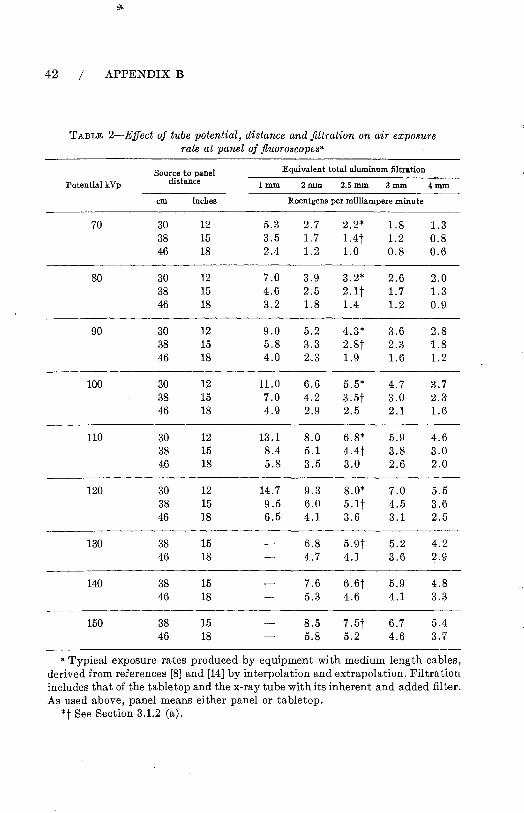
42 / APPENDIX B
TABLE 2-Effect of tube potential, distance and filtration on air exposure rate at panel of fluoroscopes"
Source to panel Equivalent total aluminum filtration
Potential kVp distance lmm 2mm 2.5mm 3mm 4mm
em inches Roentgens per milliampere minute
70 30 12 5.3 2.7 2.2* 1.8 1.3 38 15 3.5 1.7 1.4t 1.2 0.8 46 18 2.4 1.2 1.0 0.8 0.6
80 30 12 7.0 3.9 3.2* 2.6 2.0 38 15 4.6 2.5 2.1 t 1.7 1.3 46 18 3.2 1.8 1.4 1.2 0.9
90 30 12 9.0 5.2 4.3* 3.6 2.8 38 15 5.8 3.3 2.8t 2.3 1.8 46 18 4.0 2.3 1.9 1.6 1.2
100 30 12 11.0 6.6 5.5* 4.7 3.7 38 15 7.0 4.2 3.5t 3.0 2.3 46 18 4.9 2.9 2.5 2.1 1.6
110 30 12 13.1 8.0 6.8* 5.9 4.6 38 15 8.4 5.1 4.4t 3.8 3.0 46 18 5.8 3.5 3.0 2.6 2.0
120 30 12 14.7 9.3 8.0* 7.0 5.5 38 15 9.5 6.0 5.1t 4.5 3.6 46 18 6.5 4.1 3.6 3.1 2.5
130 38 15 6.8 5.9t 5.2 4.2 46 18 4.7 4.1 3.6 2.9
140 38 15 7.6 6.6t 5.9 4.8 46 18 5.3 4.6 4.1 3.3
150 38 15 8.5 7.5t 6.7 5.4 46 18 5.8 5.2 4.6 3.7
a Typical exposure rates produced by equipment with medium length cables, derived from references [8] and [14] by interpolation and extrapolation. Filtration includes that of the tabletop and the x-ray tube with its inherent and added filter. As used above, panel means either panel or tabletop.
*t See Section 3.1.2 (a).

TABLE 3-Half-value layers a8 a function of filtration and tube potential for diagnostic units"
Total Peak Potential (kVp)
Filtration 30 40 SO 60 70 80 90 100 110 120 mmAl
Typical half-value-layers in millimeters of aluminum
0.5 0.36· 0.47· 0.58 0.67 0.76 0.84 0.92 1.00 1.08 1.16 1.0 0.55 0.78 0.95 1.08 1.21 1.33 1.46 1.58 1.70 1.82 1.5 0.78 1.04 1.25" 1.42· 1.59· 1.75 1.90 2.OS 2.25 2.42 2.0 0.92 1.22 1.49 1.70 1.90 2.10 2.28 2.48 2.70 2.90 2.5 1.02 1.38 1.69 1.95 2.16 2.37·t 2.58·t 2.82·t 3.00·t 3.BO·t 3.0 1.49 1.87 2.16 2.40 2.62 2.86 3.12 3.38 3.65 3.5 1.58 2.00 2.34 2.60 2.86 3.12 3.40 3.68 3.95
a For full-wave rectified potential. Derived from reference [14] by interpolation and extrapolation . • Recommended minimum HVL for radiographio units. See Seotion 3.2.2 (a). t Recommended minimum HVL for fluoroscopes. See Section 3.1.2 (b).
TABLE 4-Exp08ure rate through fluoro8copic screen without patient" Total Filtration: 3 rom aluminum equivalent Table top to Screen dista,nce: 14 inches Screen to Chamber distance: 2 inches Medium length High Tension Cables
Source to table top Lead Equivalent of Screen Protective Barrierb
X-ray Tube distance 1.5mm 1.8mm 2.0mm Potential kVp
Typical Exposure Rate: mR/h per R/min at inches cm Tabletop
80 12 30 10 4.5 2.5 15 38 13 6 3.5 18 46 15 7 4
90 12 30 12 6 3.5 15 38 16 7.5 4.5 18 46 19 9 5.5
100 12 30 15 7 4.5 15 38 20 9 5.5 18 46 23 11 7
110 12 30 19 9 5.5 15 38 24 12 7 18 46 29 14 8.5
120 12 30 23 11 7 15 38 30 14 9 18 46 35 17 10
130 15 38 35 17 10 18 46 42 20 12
140 15 38 41 19 12 18 46 49 23 14
150 15 38 46 20 12 18 46 55 24 15
"Adapted from reference [8] by interpolation and extrapolation. Actual exposure rate values may differ from the typical values given above by :±15% depending upon length of high tension cables.
b See Seotion 3.1.1 (d) and 3.1.2 (0).

44 I APPENDIX B
TABLE 5-Scattered radiation exposure rate at side of fluoroscopy table"
Phantom: 100 lb Sack of flour 15 inch source-panel distance 10 X 10 em field at tabletop Phantom edge 6 inches from side of table
Exposure Rate in mR per rnA-hour Peak Potential
kVp No screen drape
80 90
100 110 120 130 140 150
"After J. S. Krohmer (unpublished). b 0.3 mm lead e·quivalent.
300 400 650 850
1050 1330 1550 1750
With screen drapeb
4.5 8.0
17.5 32 42 60 77 98
TABLE 6-Average exposure rates produced by diagnostic x-ray equipment"
Distance from Tube potential Source. to Point of Measurement 50kVp 60kVp 70 kVp 80kVp 90kVp 100 kVp 125 kVp
in em Roentgens per 100 milliampere seconds
12 30 1.8 2.8 4.2 5.8 8.0 9.8 15.2 18 46 0.8 1.3 1.8 2.5 3.4 4.2 6.7 24 61 0.4 0.7 1.1 1.4 1.9 2.3 3.8 39 100 0.2 0.3 0.4 0.5 0.7 0.9 1.4 54 137 0.1 0.1 0.2 0.3 0.4 0.5 0.7 72 183 0.1 0.1 0.1 0.2 0.2 0.3 0.4
• Measured in air with total filtration equivalent to 2.5 mm aluminum.

TABLES / 45
TABLE 7-Thickness of lead required to reduce useful beam to 5 per centa
Beam Quality Required Lead
Potential Half Value Layer Thickness millimeters millimeters
60 kVp 1.2 Al 0.10 100 kVp 1.0 Al 0.16 100 kVp 2.0 Al 0.25 100 kVp 3.0 Al 0.35 14.0 kVp 0.5 Cu 0.7 200 kVp 1.0 Cu 1.0 250 kVp 3.0 Cu 1.7 400 kVp 4.0 Cu 2.3
1000 kVp 3.2 Pb 20.5 2000 kVp 6.0 Pb 43.0 2000 kVcp 14.5 Pb 63.0 3000 kVcp 16.2 Pb 70.0 6000 kV 17.0 Pb 74.0 8000 kV 15.5 Pb 67.0 Cobalt 60 10.4 Pb 47.0
a Approximate values for broad beams. Transmission data for brass, steel and other material for potentials up to 2000 kVp may be found in reference [15]. Measurements on 1000 kVp and 2000 kVp made with resonant-type therapy units. Data for 6000 kV taken from reference [16], for a linear accelerator. Data for 2000 kVcp, 3000 kVcp, and 8000 kV derived by interpolation from graph presented in reference [17]. The third column refers to lead or to the required equivalent lead thickness of lead-eontaining materials (e.g. lead rubber, lead glass, etc.).

APPENDIX C
Example of Emergency Procedures for Failure of Gamma-Beam Control Mechanism
The emergency procedure to be used in case of failure of the gammabeam control mechanism depends on the individual installation. The following is an example.
Emergency Procedure in Case Beam Control Fails
If the light signals indicate that the beam control mechanism has failed to terminate the exposure at the end of the preset time (for example if the red light stays on and/or the green signal does not light up) the source may still be in the "ON" position. The following steps are to be carried out in a calm manner.
FOR THE RADIATION THERAPY TECHNICIAN
1. Open the door to the treatment room. 2. If the patient is ambulatory direct him to get off the table and leave
the room. 3. If the patient is not ambulatory:
Enter the treatment room but avoid exposure to the useful beam. Pull the treatment table as far away from the useful beam as possible. Transfer the patient to a stretcher and remove him from the room.
4. Close the door. 5. Turn off the main switch at the control panel. 6. Notify the radiation therapist and radiation protection supervisor at
once.
46
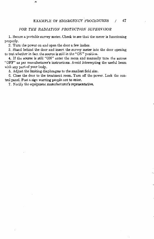
EXAMPLE OF EMERGENCY PROCEDURES / 47
'fi'OR THE RADIATION PROTECTION SUPERVISOR
1. Secure a portable survey meter. Check to see that the meter is functioning properly.
2. Turn the power on and open the door a few inches. 3. Stand behind the door and insert the survey meter into the door opening
to test whether in fact the source is still in the "ON" position. 4. If the source is still "ON" enter the room and manually turn the source
"OFF" as per manufacturer's instructions. Avoid intercepting the useful beam with any part of your body.
5. Adjust the limiting diaphragms to the smallest field size. 6. Close the door to the treatment room. Turn off the power. Lock the con
trol panel. Post a sign warning people not to enter. 7. Notify the equipment manufacturer's representative.