nchrp_rpt_469-b
DESCRIPTION
SPECSTRANSCRIPT

B-1
APPENDIX B
DESIGN EXAMPLES
B-2
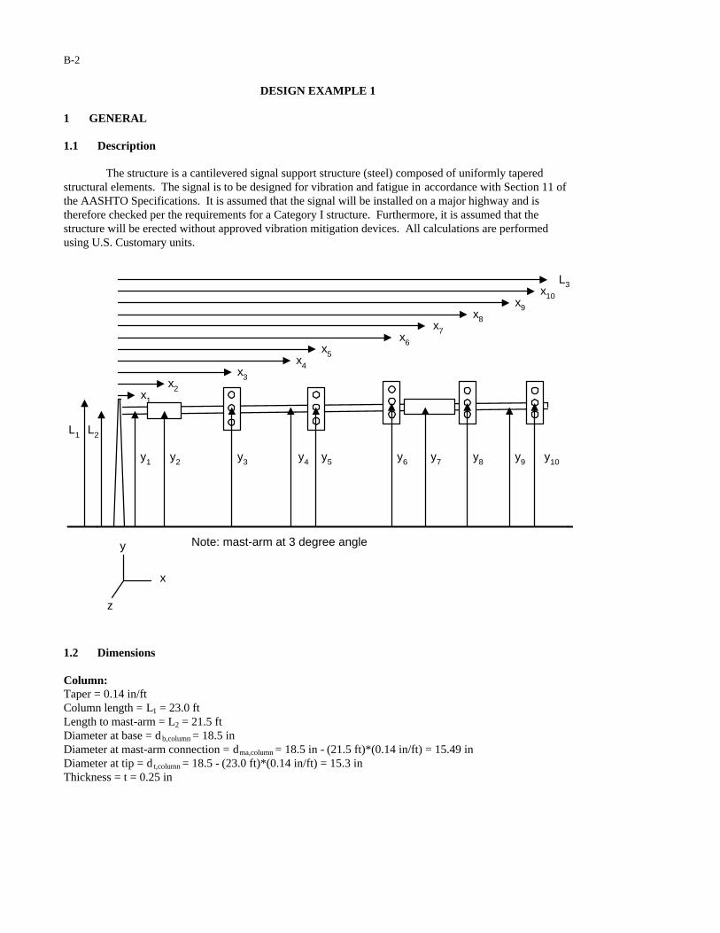
DESIGN EXAMPLE 1 1 GENERAL 1.1 Description The structure is a cantilevered signal support structure (steel) composed of uniformly tapered structural elements. The signal is to be designed for vibration and fatigue in accordance with Section 11 of the AASHTO Specifications. It is assumed that the signal will be installed on a major highway and is therefore checked per the requirements for a Category I structure. Furthermore, it is assumed that the structure will be erected without approved vibration mitigation devices. All calculations are performed using U.S. Customary units.
L2L1
x1
x2
x3
x4
x5
x6
x7
x8
x9
x10
L3
y1 y2 y3 y4 y5 y6 y7 y8 y10y9
x
y
z
Note: mast-arm at 3 degree angle
1.2 Dimensions Column: Taper = 0.14 in/ft Column length = L1 = 23.0 ft Length to mast-arm = L2 = 21.5 ft Diameter at base = d b,column = 18.5 in Diameter at mast-arm connection = dma,column = 18.5 in - (21.5 ft)*(0.14 in/ft) = 15.49 in Diameter at tip = d t,column = 18.5 - (23.0 ft)*(0.14 in/ft) = 15.3 in Thickness = t = 0.25 in
B-3
Mast-Arm Taper = 0.14 in/ft Length of mast-arm = L3 = 64 ft Horizontal distance to signal 1 = x3 = 16 ft Horizontal distance to signal 2 = x5 = 28.5 ft Horizontal distance to signal 3 = x6 = 40 ft Horizontal distance to signal 4 = x8 = 50 ft Horizontal distance to signal 5 = x10 = 62 ft Horizontal distance to sign 1 = x2 = 6 ft Horizontal distance to sign 2 = x7 = 46 ft Note: mast-arm is divided into three sections to improve the accuracy of the natural wind gust load
calculations. Horizontal distance to centroid of mast-arm section 1 = x1 = (6 - (4.5/2))/2 = 1.87 ft Horizontal distance to centroid of mast-arm section 2 = x4
= (6 + (4.5/2)) + [(46 - (7.5/2)) - (6 + (4.5/2))]/2 = 25.25 ft Horizontal distance to centroid of mast-arm section 3 = x9
= (46 + (7.5/2)) + [(64 - (46 + (7.5/2))]/2 = 56.88 ft Length of mast-arm section 1 = M1 = (6 - (4.5/2)) = 3.75 ft Length of mast-arm section 2 = M2 = (46 - (7.5/2) - (6 + (4.5/2))) = 34.00 ft Length of mast-arm section 3 = M3 = (64 - (46 + (7.5/2))) = 14.25 ft Height to signal 1 = y3 = 21.5 + (tan 3o)*16 = 22.34 ft Height to signal 2 = y5 = 21.5 + (tan 3o)*28.5 = 22.99 ft Height to signal 3 = y6 = 21.5 + (tan 3o)*40 = 23.60 ft Height to signal 4 = y8 = 21.5 + (tan 3o)*50 = 24.12 ft Height to signal 5 = y10 = 21.5 + (tan 3o)*62 = 24.75 ft Height to sign 1 = y2 = 21.5 + (tan 3o)*6 = 21.81 ft Height to sign 2 = y7 = 21.5 + (tan 3o)*46 = 23.91 ft Height to centroid of mast-arm section 1 = y1 = 21.5 + (tan 3o)*1.87 = 21.60 ft Height to centroid of mast-arm section 2 = y4 = 21.5 + (tan 3o)*25.25 = 22.82 ft Height to centroid of mast-arm section 3 = y9 = 21.5 + (tan 3o)*56.88 = 24.48 ft Diameter at mast-arm connection = db,mast-arm = 15 in Thickness = t = 0.25 in Signal: Area projected on a vertical plane: vsigA )( = 8.7 ft2
Area projected on a horizontal plane: hsigA )( = 1 ft2
Sign 1: Width of sign 1 = 4.5 ft
Area projected on a vertical plane: vsignA )( 1, = 6.75 ft2
Sign 2: Width of sign 2 = 7.5 ft
Area projected on a vertical plane: vsignA )( 2, = 11.25 ft2
B-4
Anchor Rods: Nominal anchor rod diameter = dar = 1.75 in Thread series = 5 UNC Number of anchor rods = 6 Anchor rod circle diameter = darc = 25.5 in Effective anchor rod area = AT,ar = 1.90 in2
Flange Plate Bolts: Nominal bolt diameter = db = 1.5 in Thread series = 8 UN Number of bolts = 4 Effective bolt area = AT,b = 1.49 in2
1.3 Critical Fatigue Details The structure contains the following details, which must be checked for fatigue. 1. Anchor Rods (Detail 5 in Table 11-2) 2. Column-to-baseplate fillet-welded connection (Detail 16 in Table 11-2) 3. Mast-arm-to-column connection (Details 5, 16, 17, and 19 in Table 11-2) 2 CALCULATION OF LIMIT STATES FATIGUE LOADS 2.1 Galloping The equivalent static shear range to be applied to each of the signal and sign attachments is calculated inaccordance with Equation 11-1:
psfIP FG 0.21)0.1)(0.21(0.21 ===
Where IF = 1.0 (Table 11-1) is the importance factor used in the design of a Category I signal support structure for galloping. The equivalent static shear load ranges to be applied to each of the signal and sign attachments are calculated by:
APF GsigG (, = lbsftpsfvsig 7.182)7.8)(0.21() 2 ==
lbsftpsfAPF
lbsftpsfAPF
vsignGsignG
vsignGsignG
25.236)25.11)(0.21()(
75.141)75.6)(0.21()(
22,2,
21,1,
===
===
2.2 Vortex Shedding As per the requirements of Section 11.7.2, vortex shedding need not be considered in the design of cantilevered signal support structures for vibration and fatigue.

B-5
2.3 Natural Wind Gusts It is assumed that the signal will be erected at a location where the yearly mean wind velocity is 11mph. Therefore, Equation 11-5 is applied without modification. The equivalent static pressure range to be applied to the structure is calculated in accordance with Equation 11-5:
psfCCICP ddFdNW 2.5)0.1(2.52.5 ===
Where IF = 1.0 (Table 11-1) is the importance factor used in the design of a Category I signal support structure for natural wind. The equivalent static load ranges to be applied to the column, mast-arm, signal attachments and sign attachments, respectively, are calculated by:
lbsftAPF
lbsftAPF
lbsftAPF
lbsinftinftdMPF
lbsinftinftdMPF
lbsinftinftdMPF
lbsinftinftdLPF
vsignNWsignNW
vsignNWsignNW
vsigNWsigNW
aveNWmastNW
aveNWmastNW
aveNWmastNW
aveNWcolNW
20.70)25.11)(2.1(2.5)()(
12.42)75.6)(2.1(2.5)()(
29.54)7.8)(2.1(2.5)()(
99.47)12/1)(040.7)(30.14)(1.1(2.5))(()(
9.185)12/1)(47.11)(34)(1.1(2.5))(()(
35.26)12/1)(74.14)(75.3)(1.1(2.5))(()(
2.185)12/1)(89.16)(23)(1.1(2.5))(()(
22,2,
21,1,
2
333,
222,
111,
1
===
===
===
===
===
===
===
Where Cd= 1.1, 1.2 and 1.2 are conservative estimates of the drag coefficients for circular cylinders, signals and signs, respectively (Table 3-5). Note: The area of the mast arm behind each of the signal attachments has been conservatively included in the calculation of the equivalent load range. 2.4 Truck Gusts It is assumed that the support structure will be erected at a location where the posted speed limit is not significantly less than 65 mph. The equivalent static pressure range to be applied to the structure is calculated in accordance with Equation 11-6:

B-6
psfCCICP ddFdTG 6.36)0.1(6.366.36 ===
Where IF = 1.0 (Table 11-1) is the importance factor used in the design of a Category I signal support structure for truck gusts. As per the requirements of Section 11.7.4, the equivalent static pressure is to be applied along the outer 12 ft length of the mast-arm. Therefore, the equivalent static load range to be applied to the mast-arm and the outer signal are calculated, respectively, by:
lbsftAPF
lbsinftinftdftCPF
hsigTGsigTG
avedTGmastTG
92.43)0.1)(2.1(6.36)()(
99.276)12/)(88.6)(0.12)(1.1(6.36))(12)(()(
2
,12
===
===
Cd = 1.1 and 1.2 are conservative estimates of the drag coefficient for the mast arm and the horizontal surface of the signal, respectively (Table C-2). 3 CALCULATIONS OF BENDING MOMENTS 3.1 Moment Due to Galloping The bending moment at the centerline of the column (about the z-axis) is calculated by:
)()()()(][)()( 72,21,108653 xFxFxxxxxFM signGsignGsigGGz ++++++=
inkftlb
ftlbsftlbs
ftlbs
−=−=++
++++=
4.57147620
)46)(25.236()6)(75.141(
]6250405.2816)[7.182(
3.2 Moment Due to Natural Wind The bending moment at the base of the column (about the x-axis) is calculated by:
)2/()()( 1LFM colNWNWx =
)()()()(
)()()()()()(
][)(
72,21,
93,42,11,
108653
yFyF
yFyFyF
yyyyyF
signNWsignNW
mastNWmastNWmastNW
sigNW
+++++
+++++
)2/23)(2.185( ftlbs=
)91.23)(20.70()81.21)(12.42(
)48.24)(99.47()82.22)(9.185()60.21)(35.26(
]75.2412.2460.2399.2234.22)[29.54(
ftlbsftlbs
ftlbsftlbsftlbs
ftlbs
+++++
+++++
inkftlb −=−= 3.20517108

B-7
The bending moment at the mast-arm connection (about the y-axis) is calculated by:
][)()( 108653 xxxxxFM sigNWNWy ++++=
)()()()(
)()()()()()(
72,21,
93,42,11,
xFxF
xFxFxF
signNWsignNW
mastNWmastNWmastNW
+++++
]6250405.2816)[29.54( ftlbs ++++=
)46)(20.70()6)(12.42(
)88.56)(99.47()25.25)(9.185()87.1)(35.26(
ftlbsftlbs
ftlbsftlbsftlbs
+++++
inkftlb −=−= 5.25921623
Note:
It is conservatively assumed that the loads on the mast-arm sections and the column act at their respective midpoints. 3.3 Moment Due to Truck Gusts The bending moment at the centerline of the column (about the z-axis) is calculated by:
)()())2/12(()()( 103 xFftLFM sigTGmastTGTGz +−=
inkftlb
ftlbsftlbs
−=−=+=5.22518790
)62)(92.43()58)(99.276(
Note:
It is conservatively assumed that the load on the outer twelve feet of the mast-arm acts at the midpoint of the section.
B-8
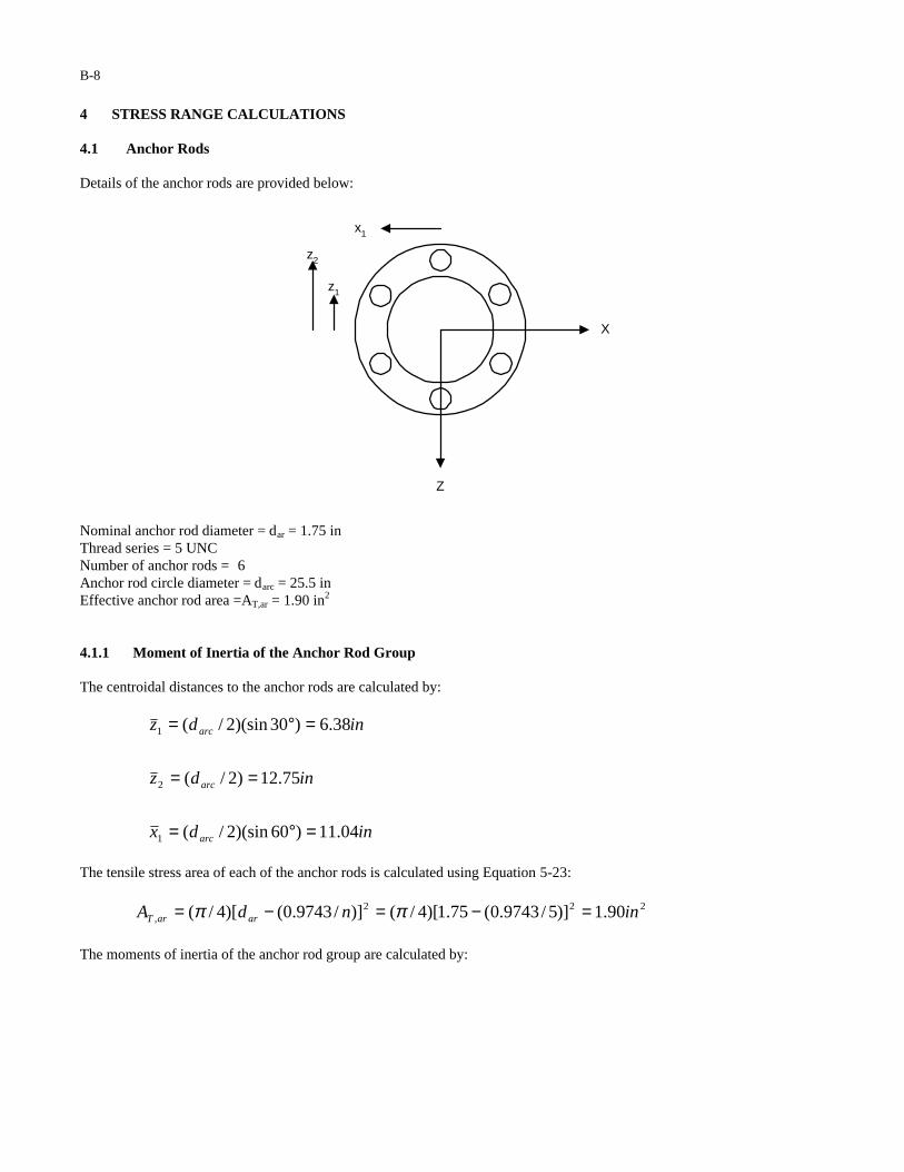
4 STRESS RANGE CALCULATIONS 4.1 Anchor Rods Details of the anchor rods are provided below:
X
Z
z2
z1
x1
Nominal anchor rod diameter = dar = 1.75 in Thread series = 5 UNC Number of anchor rods = 6 Anchor rod circle diameter = darc = 25.5 in Effective anchor rod area =AT,ar = 1.90 in2
4.1.1 Moment of Inertia of the Anchor Rod Group The centroidal distances to the anchor rods are calculated by:
indx
indz
indz
arc
arc
arc
04.11)60)(sin2/(
75.12)2/(
38.6)30)(sin2/(
1
2
1
=°=
==
=°=
The tensile stress area of each of the anchor rods is calculated using Equation 5-23:
222, 90.1)]5/9743.0(75.1)[4/()]/9743.0()[4/( inndA ararT =−=−= ππ
The moments of inertia of the anchor rod group are calculated by:
B-9
42221,
2,,
42222
22,
21,
2,,
3.926)04.11)(90.1(44
1.927)75.12)(90.1(2)38.6)(90.1(4
24
inininxAxAI
ininininin
zAzAzAI
arTarTzar
arTarTarTxar
===∑=
=+=
+=∑=
4.1.2 Anchor Rod Stress Range Based upon the calculations of Section 3, the anchor rod group must be checked with respect to galloping for the moments about the z-axis and natural wind for moments about the x-axis. Therefore, the maximum axial stress range found in an anchor rod is calculated by:
ksiinininkIzMS
ksiinininkIxMS
xarNWxxarR
zarGzzarR
82.2)1.927/()75.12)(3.205(/)()()(
81.6)3.926/()04.11)(4.571(/)()()(
4,2,
4,1,
=−==
=−==
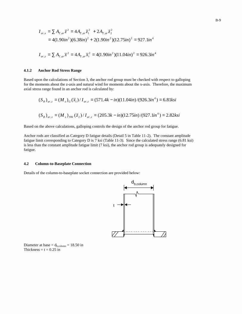
Based on the above calculations, galloping controls the design of the anchor rod group for fatigue. Anchor rods are classified as Category D fatigue details (Detail 5 in Table 11-2). The constant amplitude fatigue limit corresponding to Category D is 7 ksi (Table 11-3). Since the calculated stress range (6.81 ksi) is less than the constant amplitude fatigue limit (7 ksi), the anchor rod group is adequately designed for fatigue. 4.2 Column-to-Baseplate Connection Details of the column-to-baseplate socket connection are provided below:
t
db,column
Diameter at base = db,column = 18.50 inThickness = t = 0.25 in

B-10
4.2.1 Moment of Inertia The moment of inertia of the column is calculated by:
])2()[64/( 4,
4, tddI columnbcolumnbcol −−= π
4
44
9.596
]))25.0(25.18()5.18)[(64/(
in
ininin
=−−= π
4.2.2 Column Stress Range Based upon the calculations of Section 3, galloping controls the design of the column-to-baseplate connection for fatigue. Therefore, the stress range at the column is calculated by:
)9.596/()2/5.18)(4.571(/)2/()()( 4, inininkIdMS colcolumnbGzcolR −==
ksi85.8= The column-to-baseplate socket connection is classified as a Category E’ fatigue detail (Detail 16 in Table 11-2). The constant amplitude fatigue limit corresponding to Category E’ is 2.6 ksi (Table 11-3). Since the calculated stress range (8.85 ksi) is greater than the constant amplitude fatigue limit (2.6 ksi), the socket connection is inadequately designed for fatigue. Potential Redesigns: 1. Assuming: (1) the fatigue resistance of the connection is not improved (i.e. a Category E’ socket
connection (Detail 16 in Table 11-2) is used) and (2) the thickness of the column is not increased (i.e. t = 0.25 inches), the connection will be adequately designed for fatigue using a 34 inch column diameter.
2. Assuming: (1) the fatigue resistance of the connection is improved to Category E (i.e. a Category E full
penetration connection (Detail 11 in Table 11-2) is used) and (2) the thickness of the column is not increased (i.e. t = 0.25 inches), the connection will be adequately designed for fatigue using a 26 inch column diameter.
3. Assuming: (1) the fatigue resistance of the connection is improved to Category E (i.e. a Category E full
penetration connection (Detail 11 in Table 11-2) is used) and (2) the diameter of the column is not increased (i.e. db,column = 18.5 inches), the connection will be adequately designed for fatigue using a column thickness equal to 0.514 inches.
4. Assuming: (1) the fatigue resistance of the connection is improved to Category C (i.e. the column -to-
baseplate connection is fabricated with properly detailed stiffeners (Detail 21 in Table 11-2), and (2) the thickness of the column is not increased (i.e. t = 0.25 inches), the connection will be adequately designed for fatigue using 17.5 inch column diameter.
4.3 Mast-Arm-to-Column Connection The mast-arm-to-column connection (built-up box) is composed of three components that must be checked for fatigue: (1) flange-plate bolt group, (2) mast-arm-to-flange-plate socket connection, and (3) built-up box. Each of these components will be considered individually in the following:
B-11
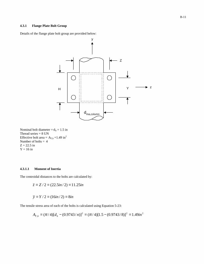
4.3.1 Flange Plate Bolt Group Details of the flange plate bolt group are provided below:
Z
YHz
y
dma,column
Nominal bolt diameter = db = 1.5 in Thread series = 8 UN Effective bolt area = AT,b =1.49 in2
Number of bolts = 4 Z = 22.5 in Y = 16 in 4.3.1.1 Moment of Inertia The centroidal distances to the bolts are calculated by:
ininYy
ininZz
8)2/16(2/
25.11)2/5.22(2/
===
===
The tensile stress area of each of the bolts is calculated using Equation 5-23:
222, 49.1)]8/9743.0(5.1)[4/()]/9743.0()[4/( inndA bbT =−=−= ππ
B-12
The moment of inertia of the bolt group is calculated by:
4222,
2,,
4222,
2,,
3.755)25.11)(49.1(4))((4
0.382)8)(49.1(4))((4
inininzAzAI
inininyAyAI
bTbTybolt
bTbTzbolt
===∑=
===∑=
4.3.1.2 Flange Plate Bolt Stress Range Based upon the calculations of Section 3, the flange plate bolt group must be checked with respect to galloping for moments about the z-axis and natural wind for moments about the y-axis. Therefore, the bolt stress ranges are calculated by:
ksiinininkIzMS
ksiinininkIyMS
yboltNWyyboltR
zboltGzzboltR
87.3)3.755/()25.11)(5.259(/)()()(
0.12)382/()8)(4.571(/)()()(
4,,
4,,
=−==
=−==
Based upon the above calculations, galloping controls the design of the bolt group for fatigue. Bolts are classified as Category D fatigue details (Detail 5 in Table 11-2). The constant amplitude fatigue limit corresponding to Category D is 7 ksi (Table 11-3). Since the calculated stress range (12.0 ksi) is greater than the constant amplitude fatigue limit (7 ksi), the anchor rod group is inadequately designed for fatigue. Potential Redesigns: 1. Assuming the bolt diameter is not increased (i.e. db = 1.5 inches), the connection will be adequately
designed for fatigue if the flange plate size is increased so that Y = 27.5 inches. 2. Assuming the size of the flange plate is not increased, the connection will be adequately designed for
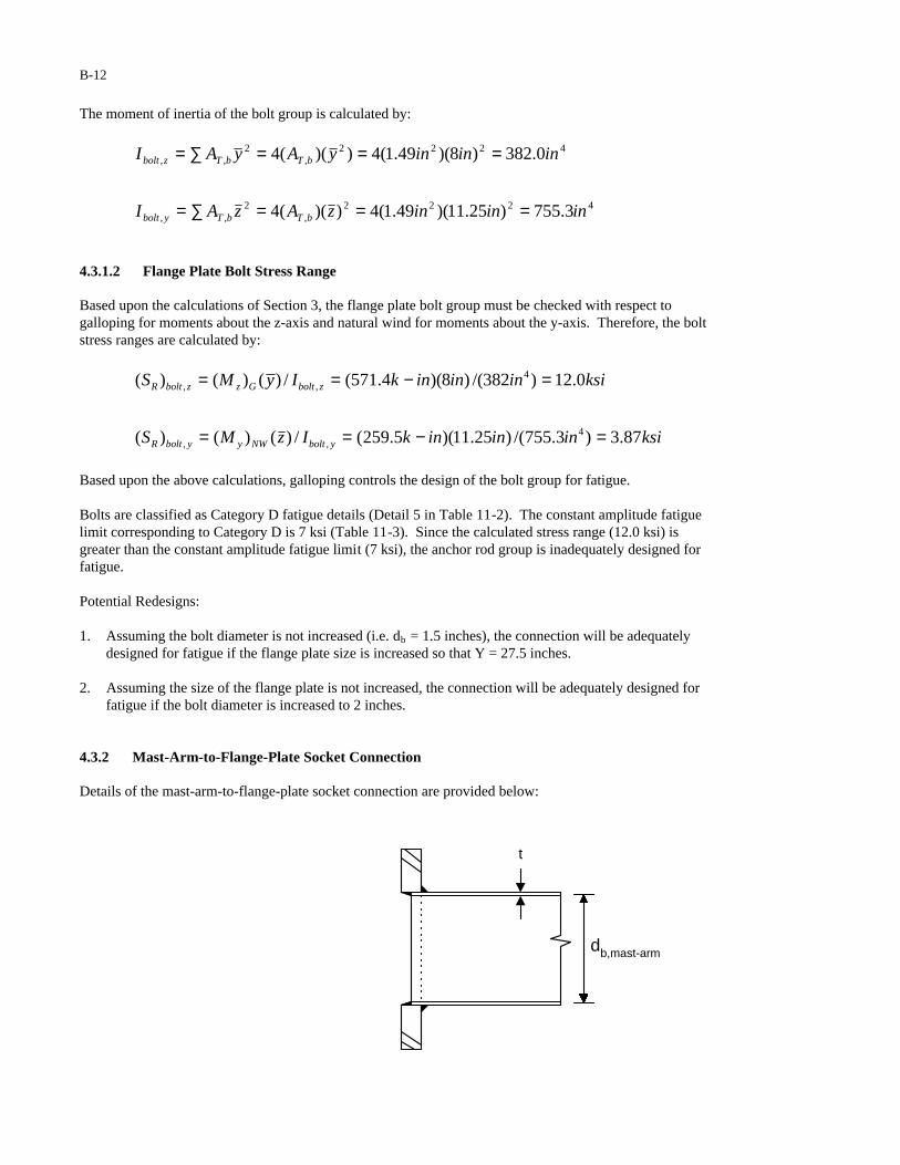
fatigue if the bolt diameter is increased to 2 inches. 4.3.2 Mast-Arm-to-Flange-Plate Socket Connection Details of the mast-arm-to-flange-plate socket connection are provided below:
t
db,mast-arm
B-13
Diameter at base = db,mast-arm = 15 in Thickness = t = 0.25 in 4.3.2.1 Moment of Inertia The moment of inertia of the mast-arm is calculated by :
])2()[64/( 4,
4, tddI mast-armbmast-armbarm −−= π
4
44
1.315
]))25.0(215()15)[(64/(
in
ininin
=−−= π
4.3.2.2 Mast-Arm Stress Range Based upon the calculation of Section 3, galloping controls the design of the mast-arm-to-flange-plate socket connection for fatigue. Therefore, the mast-arm stress range is calculated by:
ksiinininkIdMS armmast-armbGzarmR 6.131.315/)2/15)(4.571(/)2/()()( 4, =−==
The mast-arm-to-flange-plate socket connection is classified as a Category E’ fatigue detail (Detail 16 of Table 11-2). The constant amplitude fatigue limit corresponding to Category E’ is 2.6 ksi (Table 11-3). Since the calculated stress range (13.6 ksi) is greater than the constant amplitude fatigue limit (2.6 ksi), the socket connection is inadequately designed for fatigue. Potential Redesigns: 1. Assuming: (1) the fatigue resistance of the connection is not improved (i.e. a Category E’ socket
connection (Detail 16 in Table 11-2) is used) and (2) the thickness of the mast-arm is not increased (i.e. t = 0.25 inches), the connection will be adequately designed for fatigue using a 34 inch mast-arm diameter.
2. Assuming: (1) the fatigue resistance of the connection is improved to Category E (i.e. a Category E
full-penetration connection (Detail 11 in Table 11-2) is used) and (2) the thickness of the mast-arm is not increased (i.e. t = 0.25 inches), the connection will be adequately designed for fatigue using a 26 inch mast-arm diameter.
3. Assuming: (1) the fatigue resistance of the connection is improved to Category E (i.e. a Category E
full-penetration connection (Detail 11 in Table 11-2) is used) and (2) the diameter of the mast-arm is increased to 23.5 inches (i.e. db,mast-arm = 23.5 inches), the connection will be adequately designed for fatigue using a mast-arm thickness equal to 0.3125 inches.
B-14
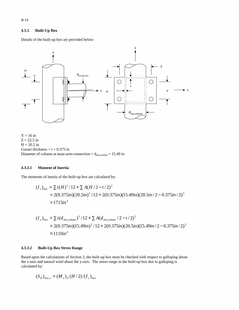
4.3.3 Built-Up Box Details of the built-up box are provided below:
H
Y
y
x
db,mast-arm
Z
YHz
y
t
t
dma,column
Y = 16 in Z = 22.5 in H = 20.5 in Gusset thickness = t = 0.375 in Diameter of column at mast-arm-connection = dma,column = 15.49 in 4.3.3.1 Moment of Inertia The moments of inertia of the built-up box are calculated by:
23 )2/2/(12/)()( tHAHtI boxz −∑+∑=
4
23
1715
)2/375.02/5.20)(49.15)(375.0(212/)5.20)(375.0(2
in
inininininin
=−+=
2,
3, )2/2/(12/)()( tdAdtI columnmacolumnmaboxy −∑+∑=
4
23
1110
)2/375.02/49.15)(5.20)(375.0(212/)49.15)(375.0(2
in
inininininin
=−+=
4.3.3.2 Built-Up Box Stress Range Based upon the calculations of Section 3, the built-up box must be checked with respect to galloping about the z-axis and natural wind about the y-axis. The stress range in the built-up box due to galloping is calculated by:
boxzGzzboxR IHMS )/()2/()()( , =

B-15
ksi
ininink
42.3
)1715/()2/5.20)(4.571( 4
=−=
The stress range in the built-up box due to natural wind gusts is calculated by:
boxycolumnmaNWyyboxR IdMS )/()2/()()( ,, =
ksi
ininink
81.1
)1110/()2/49.15)(5.259( 4
=−=
Based upon the above calculations, galloping controls the design of the built-up box for fatigue. The built-up-box-to-flange-plate connection is classified as a Category E’ fatigue detail (Detail 17 in Table 11-2). The constant amplitude fatigue limit corresponding to Category E’ is 2.6 ksi (Table 11-3). Since the calculated stress range (3.42 ksi) is greater than the constant amplitude fatigue limit (2.6 ksi), the connection is inadequately designed for fatigue. The branching member (built-up box) of the built-up-box-to-column connection is classified as a Category ET fatigue detail (Detail 19, Note (b) in Table 11-2). The constant amplitude fatigue limit corresponding to Category ET is 1.2 ksi (Table 11-3). Since the calculated stress range (3.42 ksi) is greater than the constant amplitude fatigue limit (1.2 ksi), the connection is inadequately designed for fatigue. The nominal in-plane stress range in the main member (column) is calculated using the following relationship (Note (b) from Table 11-2):
( ) ( ) ( ) ( ) ksiin
inksi
t
tSS
c
bmemberbranchingRmembermainR 44.367.0
25.0
375.042.3 =
=
= α
Where (Sr)branching member is the calculated in-plane nominal stress range in the branching member induced by fatigue loads, tb is the wall thickness of the branching member (built-up box), tc is the wall thickness of the main member (column), and α is the in-plane bending ovalizing parameter for the main member. The nominal out-of-plane stress range in the main member (column) is calculated using the following relationship (Note (b) from Table 11-2):
( ) ( ) ( ) ( ) ksiin
inksi
t
tSS
c
bmemberbranchingRmembermainR 07.45.1
25.0
375.081.1 =
=
= α
Where (Sr)branching member is the calculated out-of-plane nominal stress range in the branching member induced by fatigue loads, tb is the wall thickness of the branching member (built-up box), tc is the wall thickness of the main member (column), and α is the out-of-plane bending ovalizing parameter for the main member. The main member (column) of the built-up-box-to-column connection is classified as a Category K2 fatigue detail (Detail 19, Note (b) in Table 11-2). The constant amplitude fatigue limit corresponding to Category K2 is 1.0 ksi (Table 11-3). However, the r/t ratio of the column at the location of the mast-arm is greater than 24. Therefore, the fatigue resistance has to be reduced in accordance with the following relationship (Note (b) from Table 11-2):
B-16
( ) ( ) ( ) ( ) ksi
inin
ksi
tr
FF Knn 84.0
25.02/49.15
240.1
247.07.0
2 =
×=
×∆=
Where ( ) 2KnF∆ is the CAFL for Category K2.
Since the calculated stress range (4.07 ksi) is greater than the constant amplitude fatigue limit (0.84 ksi), the connection is inadequately designed for fatigue. The main member (column) must also be checked for a Category E fatigue detail at the bottom of the welded connection to the branching member (built-up box) (Detail 19, Note (b) in Table 11-2). This stress, which is controlled by galloping, is calculated by:
( ) ( ) ( ) ( )( )ksi
in
inink
I
dMS
col
columnmaGz
colR 73.126.347
2/49.154.5712/4
, =−==
The constant amplitude fatigue limit corresponding to Category E is 4.5 ksi (Table 11-3). Since the calculated stress range (12.73 ksi) is greater than the constant amplitude fatigue limit (4.5 ksi), the column is inadequately designed for infinite fatigue life. Potential Redesigns: 1. Assuming: (1) the fatigue resistance of the connection is not improved (i.e. a Category K2 connection
(Detail 19 in Table 11-2) is used to attach the built-up box to the column) and (2) the box width remains equal to the diameter of the column, the connection will be adequately designed for fatigue using a box height, H, equal to 34 inches, a column diameter at the location of the mast-arm of 20 inches with a 0.5-inch thickness, and box plate thickness of 0.5 inches.
2. Assuming: (1) the fatigue resistance of the connection is not improved (i.e. a Category K2 connection
(Detail 19 in Table 11-2) is used to attach the built-up box to the column) and (2) the box width remains equal to the diameter of the column, the connection will be adequately designed for fatigue using a box height, H, equal to 34 inches, a column diameter at the location of the mast-arm of 18 inches with a 0.75-inch thickness, and box plate thickness of 0.5 inches.
3. Assuming: (1) the fatigue resistance of the connection is not improved (i.e. a Category K2 connection
(Detail 19 in Table 11-2) is used to attach the built-up box to the column) and (2) the box width remains equal to the diameter of the column, the connection will be adequately designed for fatigue using a box height, H, equal to 32 inches, a column diameter at the location of the mast-arm of 20 inches with a 0.75-inch thickness, and box plate thickness of 0.5 inches.
5 DEFLECTION Section 11.8 limits the vertical-plane mast-arm displacement to 8 inches under application of the limit states fatigue design load. Based upon the calculations of Section 3, galloping controls the design of the structure with respect to the deflection limit state.
B-17
5.1 Vertical-Plane Displacement Range of the Original Structure 5.1.1 Assumptions (1) The displacement range at the tip of the mast-arm is calculated using the superposition of the following
displacement components:
1∆ : Displacement range at the tip of the mast-arm due to the deflection of the mast-arm (assuming a
cantilever beam fixed at the base of the mast-arm) under application of 1,signGF = 141.8lbs to sign 1.
2∆ : Displacement range at the tip of the mast-arm due to the deflection of the mast-arm (assuming a
cantilever beam fixed at the base of the mast-arm) under application of sigGF , = 182.7lbs to signal 1.
3∆ : Displacement range at the tip of the mast-arm due to the deflection of the mast-arm (assuming a
cantilever beam fixed at the base of the mast-arm) under application of sigGF , = 182.7lbs to signal 2.
4∆ : Displacement range at the tip of the mast-arm due to the deflection of the mast-arm (assuming a
cantilever beam fixed at the base of the mast-arm) under application of sigGF , = 182.7lbs to signal 3.
5∆ : Displacement range at the tip of the mast-arm due to the deflection of the mast-arm (assuming a
cantilever beam fixed at the base of the mast-arm) under application of 2,signGF = 236.3lbs to sign 2.
6∆ : Displacement range at the tip of the mast-arm due to the deflection of the mast-arm (assuming a
cantilever beam fixed at the base of the mast-arm) under application of sigGF , = 182.7lbs to signal 4.
7∆ : Displacement range at the tip of the mast-arm due to the deflection of the mast-arm (assuming a
cantilever beam fixed at the base of the mast-arm) under application of sigGF , = 182.7lbs to signal 5.
8∆ : Displacement range at the tip of the mast-arm due to the rotation of the column (assuming a
cantilever beam fixed at the base of the column) under application of the moment GzM )( = 571.4 k-in.
(2) Calculation of each of the displacement quantities noted above is based upon the average moment of
inertia of each of the components. 5.1.2 Average Moment of Inertia of Column From previous calculations, the moment of inertia at the base of the column is:
4, 9.596 inI basecol =
The moment of inertia of the column at the mast-arm connection is :
])2()[64/( 4,
4,, tddI columnmacolumnmamacol −−= π
4
44
6.347
]))25.0(249.15()49.15)[(64/(
in
ininin
=−−= π
The average moment of inertia of the column is:

B-18
444,,, 2.4722/)6.3479.596(2/)( inininIII macolbasecolavecol =+=+=
5.1.3 Average Moment of Inertia of Mast-Arm From previous calculations, the moment of inertia at the base of the mast-arm is:
4, 1.315 inI basearm =
The moment of inertia at the tip of the mast-arm is:
])2()[64/( 4,
4,, tddI mast-armtipmast-armtiptiparm −−= π
4
44
09.19
]))25.0(204.6()04.6)[(64/(
in
ininin
=−−= π
The average moment of inertia of the mast is:
444,,, 1.1672/)1.191.315(2/)( inininIII tiparmbasearmavemast =+=+=
5.1.4 Mast-Arm Displacement Range 1∆
The displacement range at the tip of the mast-arm due to the galloping load applied to sign 1 is calculated by:
])(3)][6/())([( 23,2
21,1 xLEIxF avemastsignG −=∆
in
ftftinksiftinftk
06.0
]6)64(3))][1.167)(29000)(6/(()/1728()6)(1418.0[( 4332
=−=
5.1.5 Mast-Arm Displacement Range 2∆
The displacement range at the tip of the mast-arm due to the galloping load applied to signal 1 is calculated by:
])(3)][6/())([( 33,2
3,2 xLEIxF avemastsigG −=∆
in
ftftinksiftinftk
49.0
]16)64(3))][1.167)(29000)(6/(()/1728()16)(1827.0[( 4332
=−=
5.1.6 Mast-Arm Displacement Range 3∆
The displacement range at the tip of the mast-arm due to the galloping load applied to signal 2 is calculated by:

B-19
])(3)][6/())([( 53,2
5,3 xLEIxF avemastsigG −=∆
in
ftftinksiftinftk
44.1
]5.28)64(3))][1.167)(29000)(6/(()/1728()5.28)(1827.0[( 4332
=−=
5.1.7 Mast-Arm Displacement Range 4∆
The displacement range at the tip of the mast-arm due to the galloping load applied to signal 3 is calculated by:
])(3)][6/())([( 63,2
6,4 xLEIxF avemastsigG −=∆
in
ftftinksiftinftk
64.2
]40)64(3))][1.167)(29000)(6/(()/1728()40)(1827.0[( 4332
=−=
5.1.8 Mast-Arm Displacement Range 5∆
The displacement range at the tip of the mast-arm due to the galloping load applied to sign 2 is calculated by:
])(3)][6/())([( 73,2
72,5 xLEIxF avemastsignG −=∆
in
ftftinksiftinftk
34.4
]46)64(3))][1.167)(29000)(6/(()/1728()46)(2363.0[( 4332
=−=
5.1.9 Mast-Arm Displacement Range 6∆
The displacement range at the tip of the mast-arm due to the galloping load applied to signal 4 is calculated by:
])(3)][6/())([( 83,2
8,6 xLEIxF avemastsigG −=∆
in
ftftinksiftinftk
85.3
]50)64(3))][1.167)(29000)(6/(()/1728()50)(1827.0[( 4332
=−=
5.1.10 Mast-Arm Displacement Range 7∆
The displacement range at the tip of the mast-arm due to the galloping load applied to signal 5 is calculated by:
])(3)][6/())([( 103,2
10,7 xLEIxF avemastsigG −=∆
in
ftftinksiftinftk
43.5
]62)64(3))][1.167)(29000)(6/(()/1728()62)(1827.0[( 4332
=−=

B-20
5.1.11 Mast-Arm Displacement Range 8∆
The rotation of the column at the location of the mast-arm is calculated by :
)]2.472)(29000/[()/12)(5.21)(4.571()/()()( 4,2 inksiftinftinkEILM avecolGzcol −==θ
radians0108.0= The displacement range at the tip of the mast-arm due to the rotation of the column is calculated by:
inftinftradiansLcol 27.8)/12)(64)(0108.0(38 ===∆ θ
5.1.12 Total Mast-Arm Deflection Range total∆
The total displacement range at the tip of the mast-arm is obtained by the superposition of each of the deflection quantities:
87654321 ∆+∆+∆+∆+∆+∆+∆+∆=∆ total
in
inininininininin
5.26
27.843.585.334.464.244.149.006.0
=+++++++=
The allowable vertical-plane mast-arm displacement from Section 11.8 is 8 inches. The computed deflection range at the tip of the mast-arm (26.5 in) exceeds the allowable deflection range (8 in). Therefore, the structure is inadequately designed with respect to the deflection limit state. 5.2 Vertical-Plane Displacement Range of the Redesigned Structure 5.2.1 Assumptions (1) It is assumed that the following geometric properties are increased: Column Mast-Arm db,column = 25.5 in db,mast-arm = 22.0 in dma,column = 22.49 in dtip,mast-arm = 13.04 in (2) The assumptions used in the calculations shown in Section 5.1 of this example are also used in the
calculations that follow. 5.2.2 Average Moment of Inertia of Column The moment of inertia at the base of the column is:
])2()[64/( 4,
4,, tddI columnbcolumnbbasecol −−= π
4
44
1581
]))25.0(25.25()5.25)[(64/(
in
ininin
=−−= π
The moment of inertia of the column at the mast-arm connection is:

B-21
])2()[64/( 4,
4,, tddI columnmacolumnmamacol −−= π
4
44
1080
]))25.0(249.22()49.22)[(64/(
in
ininin
=−−= π
The average moment of inertia of the column is:
444,,, 13312/)10801581(2/)( inininIII macolbasecolavecol =+=+=
5.2.3 Average Moment of Inertia of Mast-Arm The moment of inertia at the base of the mast-arm is:
])2()[64/( 4,
4,, tddI mast-armbmast-armbbasearm −−= π
4
44
1010
]))25.0(20.22()0.22)[(64/(
in
ininin
=−−= π
The moment of inertia at the tip of the mast-arm is:
])2()[64/( 4,
4,, tddI mast-armtipmast-armtiptiparm −−= π
4
44
5.205
]))25.0(204.13()04.13)[(64/(
in
ininin
=−−= π
The average moment of inertia of the mast is:
444,,, 6082/)5.2051010(2/)( inininIII tiparmbasearmavemast =+=+=
5.2.4 Mast-Arm Displacement Range 1∆
The displacement range at the tip of the mast-arm due to the galloping load applied to sign 1 is calculated by:
])(3)][6/())([( 23,2
21,1 xLEIxF avemastsignG −=∆
in
ftftinksiftinftk
016.0
]6)64(3))][608)(29000)(6/(()/1728()6)(1418.0[( 4332
=−=
5.2.5 Mast-Arm Displacement Range 2∆
The displacement range at the tip of the mast-arm due to the galloping load applied to signal 1 is calculated by:
])(3)][6/())([( 33,2
3,2 xLEIxF avemastsigG −=∆

B-22
in
ftftinksiftinftk
13.0
]16)64(3))][608)(29000)(6/(()/1728()16)(1827.0[( 4332
=−=
5.2.6 Mast-Arm Displacement Range 3∆
The displacement range at the tip of the mast-arm due to the galloping load applied to signal 2 is calculated by:
])(3)][6/())([( 53,2
5,3 xLEIxF avemastsigG −=∆
in
ftftinksiftinftk
40.0
]5.28)64(3))][608)(29000)(6/(()/1728()5.28)(1827.0[( 4332
=−=
5.2.7 Mast-Arm Displacement Range 4∆
The displacement range at the tip of the mast-arm due to the galloping load applied to signal 3 is calculated by:
])(3)][6/())([( 63,2
6,4 xLEIxF avemastsigG −=∆
in
ftftinksiftinftk
73.0
]40)64(3))][608)(29000)(6/(()/1728()40)(1827.0[( 4332
=−=
5.2.8 Mast-Arm Displacement Range 5∆
The displacement range at the tip of the mast-arm due to the galloping load applied to sign 2 is calculated by:
])(3)][6/())([( 73,2
72,5 xLEIxF avemastsignG −=∆
in
ftftinksiftinftk
19.1
]46)64(3))][608)(29000)(6/(()/1728()46)(2363.0[( 4332
=−=
5.2.9 Mast-Arm Displacement Range 6∆
The displacement range at the tip of the mast-arm due to the galloping load applied to signal 4 is calculated by:
])(3)][6/())([( 83,2
8,6 xLEIxF avemastsigG −=∆
in
ftftinksiftinftk
06.1
]50)64(3))][608)(29000)(6/(()/1728()50)(1827.0[( 4332
=−=

B-23
5.2.10 Mast-Arm Displacement Range 7∆
The displacement range at the tip of the mast-arm due to the galloping load applied to signal 5 is calculated by:
])(3)][6/())([( 103,2
10,7 xLEIxF avemastsigG −=∆
in
ftftinksiftinftk
49.1
]62)64(3))][608)(29000)(6/(()/1728()62)(1827.0[( 4332
=−=
5.2.11 Mast-Arm Displacement Range 8∆
The rotation of the column at the location of the mast-arm is calculated by :
)]1331)(29000/[()/12)(5.21)(4.571()/()()( 4,2 inksiftinftinkEILM avecolGzcol −==θ
radians00382.0= The displacement range at the tip of the mast-arm due to the rotation of the column is calculated by:
inftinftradiansLcol 93.2)/12)(64)(00382.0(38 ===∆ θ
5.2.12 Total Mast-Arm Deflection Range total∆
The total displacement range at the tip of the mast-arm is obtained by the superposition of each of the deflection quantities:
87654321 ∆+∆+∆+∆+∆+∆+∆+∆=∆ total
in
inininininininin
93.7
93.249.106.119.173.040.013.0016.0
=+++++++=
The allowable vertical-plane mast-arm displacement from Section 11.8 is 8 inches. The computed deflection range at the tip of the mast-arm (7.93 in) is less than the allowable deflection range (8 in). Therefore, the structure is adequately designed with respect to the deflection limit state.
B-24
DESIGN EXAMPLE 2 1 GENERAL 1.1 Description
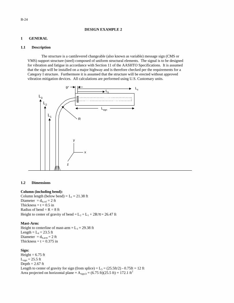
The structure is a cantilevered changeable (also known as variable) message sign (CMS or VMS) support structure (steel) composed of uniform structural elements. The signal is to be designed for vibration and fatigue in accordance with Section 11 of the AASHTO Specifications. It is assumed that the sign will be installed on a major highway and is therefore checked per the requirements for a Category I structure. Furthermore it is assumed that the structure will be erected without approved vibration mitigation devices. All calculations are performed using U.S. Customary units.
L5
L4
R
L3
L2
L1
y
x
z
Lsign
9"
1.2 Dimensions Column (including bend): Column length (below bend) = L1 = 21.38 ft Diameter = db,col = 2 ft Thickness = t = 0.5 in Radius of bend = R = 8 ft Height to center of gravity of bend = L2 = L1 + 2R/π = 26.47 ft Mast-Arm: Height to centerline of mast-arm = L3 = 29.38 ft Length = L4 = 23.5 ft Diameter = db,arm = 2 ft Thickness = t = 0.375 in Sign: Height = 6.75 ft Lsign = 25.5 ft Depth = 2.67 ft Length to center of gravity for sign (from splice) = L5 = (25.5ft/2) - 0.75ft = 12 ft Area projected on horizontal plane = Asign,h = (6.75 ft)(25.5 ft) = 172.1 ft2

B-25
Area projected on vertical plane = Asign,v = (2.67 ft)(25.5 ft) = 68.09 ft2 Anchor Rods: Nominal rod diameter = dar = 2.5 in Stress area = AT,ar = 4.00 in2
Thread series = 4 UNC Number of anchor rods = 12 Anchor rod circle diameter = darc = 33 in Splice Bolts: Nominal bolt diameter = db = 0.875 in Stress area = AT,b = 0.462 in2
Thread series = 9 UNC Number of bolts = 26 Bolt circle diameter = dbc = 27 in 1.3 Critical Fatigue Details The structure contains the following details, which must be designed for fatigue: 1. Anchor rods (Detail 5 in Table 11-2) 2. Column-to-baseplate groove-welded connection (with backing ring attached with fillet or tack weld and
left in place) (Detail 12 in Table 11-2) 3. Groove-welded stiffener at column base (Details 21 and 23 in Table 11-2) 4. Splice Plate Bolts (Detail 5 in Table 11-2) 5. Mast-arm to splice plate groove-welded connection (with backing ring attached with fillet or tack weld
and left in place) (Detail 12 in Table 11-2) 2 CALCULATION OF LIMIT STATES FATIGUE LOADS 2.1 Galloping The equivalent static shear range to be applied to the sign attachment is calculated in accordance with Equation 11-1:
psfIP FG 0.21)0.1(0.21)(0.21 ===
Where IF = 1.0 (Table 11-1) is the importance factor used in the design of a Category I sign support structure for galloping. The equivalent static shear load range to be applied to the sign attachment is calculated by:
lbsftpsfAPF vsignGG 3614)1.172(0.21)( 2, ===
B-26
2.2 Vortex Shedding As per the requirements of Section 11.7.2, vortex shedding need not be considered in the design of cantilevered sign support structures for vibration and fatigue. 2.3 Natural Wind Gusts It is assumed that the sign will be erected at a location where the yearly mean wind velocity is 11 mph. Therefore, Equation 11-5 is applied without modification. The equivalent static pressure range to be applied to the structure is calculated in accordance with Equation 11-5:
psfCCICP ddFdNW 2.5)0.1(2.5)(2.5 ===
Where IF = 1.0 (Table 11-1) is the importance factor used in the design of a Category I sign support structure for natural wind. The equivalent static load range to be applied to the column (below the bend) is calculated by:
lbsftftdLAPF colbvcolNWcolNW 6.244)2)(38.21)(1.1(2.5))()(1.1(2.5)( ,1,, ====
dC = 1.1 is a conservative estimate of the drag coefficient for a circular cylinder (Table 3-5).
The equivalent static load range to be applied to the column bend (before the sign) is calculated by:
lbsftftdftRAPF colbvbendNWbendNW 2.135)2)(82.11)(1.1(2.5))(75.2/)(1.1(2.5)( ,,, ==−== π The equivalent static load range to be applied to the sign is calculated by:
lbsftAPF vsignNWsignNW 1521)1.172)(7.1(2.5)( 2,, ===
dC = 1.7 is a conservative estimate of the drag coefficient for a variable message sign (Table 3-5).
2.4 Truck Gusts It is assumed that the support structure will be erected at a location where the posted speed limit is not significantly less than 65 mph. The equivalent static pressure range to be applied to the structure is calculated in accordance with Equation 11-6:
psfCCICP ddFdTG 6.36)0.1(6.36)(6.36 ===
Where IF = 1.0 (Table 11-1) is the importance factor used in the design of a Category I sign support structure for truck gusts. The equivalent static pressure is to be applied along the entire length of the sign. Therefore, the equivalent static load range to be applied to the sign is calculated by:

B-27
lbsftAPF hsignTGsignTG 4237)09.68)(7.1(6.36)( 2,, ===
The equivalent static load range to be applied to the mast-arm is calculated by:
lbsftftdLCAPF armdharmTGarmTG 1892)2)(5.23)(1.1(6.36))()((6.36)( 4,, ====
3 CALCULATION OF BENDING MOMENTS 3.1 Moment Due to Galloping The bending moment at the splice-plate (about the z-axis) is calculated by:
inklbftftlbsLFM GspliceGz −==== 4.52043370)12(3614)( 5,,
The bending moment at the Baseplate (about the z-axis) is calculated by:
inklbftftftlbsRLFM GbaseGz −==+=+= 4.86772280)812(3614)( 5,,
3.2 Moment Due to Natural Wind Gusts The bending moment at the splice-plate (about the y-axis) is calculated by:
inkftlbftlbsLFM signNWspliceNWy −==== 0.21918250)12)(1521())(( 5,,,
The bending moment at the base of the column (about the y-axis) is calculated by:
)2/)(())(())(( 1,2,3,,, LFLFLFM colNWbendNWsignNWbaseNWx ++=
inklbft
ftlbsftlbsftlbs
−==++=
6.61050881
)69.10)(6.244()47.26)(2.135()38.29)(1521(
3.3 Moment Due to Truck Gusts The bending moment at the splice-plate (about the z-axis) is calculated by:
)2/)(())(( 4,5,,, LFLFM armTGsignTGspliceTGz +=
inklbft
ftlbsftlbs
−==+=9.87673080
)75.11)(1892()12)(4237(
The bending moment at the Baseplate (about the z-axis) is calculated by:
)2/)(())(( 4,5,,, RLFRLFM armTGsignTGbaseTGz +++=
B-28
inklbft
ftftlbsftftlbs
−==+++=
1465122100
)875.11)(1892()812)(4237(
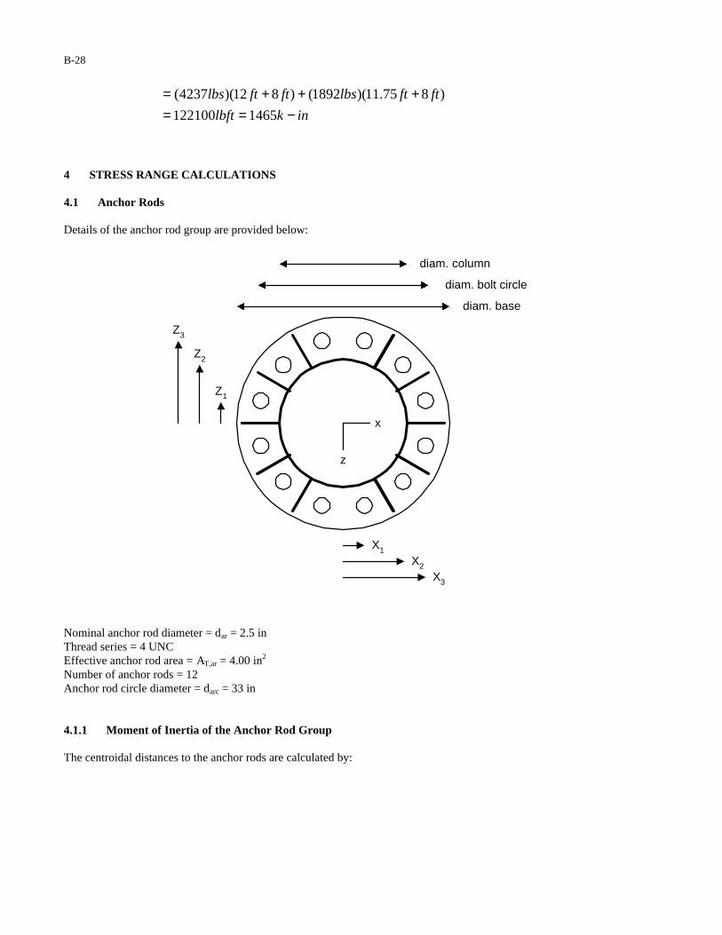
4 STRESS RANGE CALCULATIONS 4.1 Anchor Rods Details of the anchor rod group are provided below:
diam. base
diam. bolt circle
diam. column
X1
X2
X3
Z1
Z2
Z3
z
x
Nominal anchor rod diameter = dar = 2.5 in Thread series = 4 UNC Effective anchor rod area = AT,ar = 4.00 in2
Number of anchor rods = 12 Anchor rod circle diameter = darc = 33 in 4.1.1 Moment of Inertia of the Anchor Rod Group The centroidal distances to the anchor rods are calculated by:
B-29
indxz
indxz
indxz
arc
arc
arc
94.15)75)(sin2/(
67.11)45)(sin2/(
27.4)15)(sin2/(
33
22
11
=°==
=°==
=°==
The tensile stress area of each of the anchor rods is calculated using Equation 5-23:
222, 00.4]4/9743.05.2)[4/(]/9743.0)[4/( ininndA ararT =−=−= ππ
The moment of inertia of the anchor rod group (about the x and z-axes) is calculated by:
])[4)(( 23
22
21,
2, zzzAzAI arTarTar ++=∑=
)]94.15()67.11()27.4)[(4)(00.4( 2222 inininin ++=
]5.408)[4)(00.4( 22 inin=
4.1.2 Anchor Rod Stress Range Since the moments of inertia of the anchor rod group about the x- and z-axes at the baseplate are equal, only the largest moment (MZ,TG,base) needs to be checked. The axial stress range in each of the anchor rods is calculated by:
4,,,, 6536/)5.16)(1465(/)2/()( inininkIdMS zararcbaseTGzzarR −==
ksi70.3= Anchor rods are classified as Category D fatigue details (Detail 5 in Table 11-2). The constant amplitude fatigue limit corresponding to Category D is 7ksi (Table 11-3). Since the calculated stress range (3.70ksi) is less than the constant amplitude fatigue limit (7ksi), the anchor rod group is considered adequately designed for fatigue.
B-30
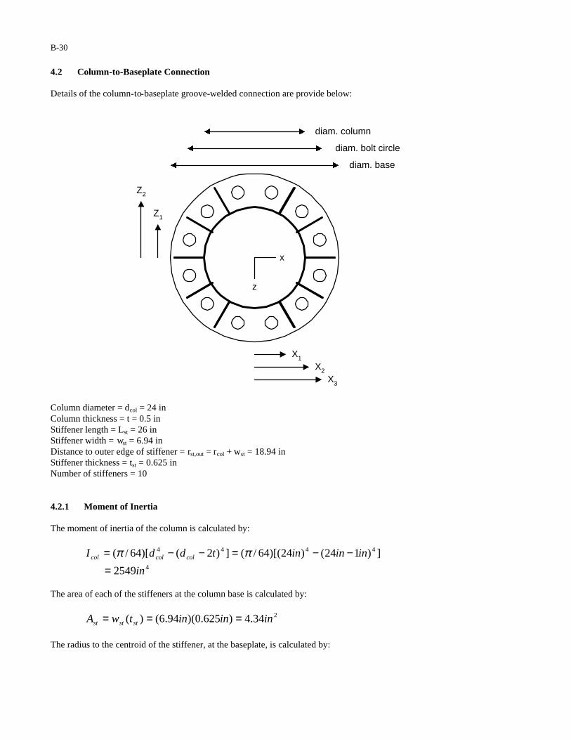
4.2 Column-to-Baseplate Connection Details of the column-to-baseplate groove-welded connection are provide below:
diam. base
diam. bolt circle
diam. column
X1
X2
X3
Z1
Z2
z
x
Column diameter = dcol = 24 in Column thickness = t = 0.5 in Stiffener length = Lst = 26 in Stiffener width = wst = 6.94 in Distance to outer edge of stiffener = rst,out = rcol + wst = 18.94 in Stiffener thickness = tst = 0.625 in Number of stiffeners = 10 4.2.1 Moment of Inertia The moment of inertia of the column is calculated by:
])124()24)[(64/(])2()[64/( 4444 ininintddI colcolcol −−=−−= ππ
42549in= The area of each of the stiffeners at the column base is calculated by:
234.4)625.0)(94.6()( ininintwA ststst ===
The radius to the centroid of the stiffener, at the baseplate, is calculated by:

B-31
inininwdr stcolst 47.15)2/94.6()2/24()2/()2/( =+=+=
The centroidal distance to each of the stiffeners is calculated by:
inrx
inrxz
inrxz
st
st
st
47.15
40.13)60(sin
74.7)30(sin
3
22
11
==
=°==
=°==
The moment of inertia at the column base (about the z-axis) is calculated by:
))((2])[(4 23
22
21
2, xAxxAIxAII ststcolstcolzcb +++=∑+=
4
22224
8780
)3.239)(34.4(2)3.239)(34.4(42549
in
ininininin
=++=
The moment of inertia at the column base (about the x-axis) is calculated by:
])[(4 22
21
2, zzAIzAII stcolstcolxcb ++=∑+=
4
224
6703
)3.239)(34.4(42549
in
ininin
=+=
Note that the individual moment of inertia of each of the stiffeners is neglected in the calculation of the moment of inertia of the column base. 4.2.2 Stress Range at Column-to-Baseplate Connection Based upon the calculations of Section 3, the groove-welded column-to-baseplate connection must bechecked with respect to truck gusts about the z-axis and natural wind about the x-axis. The stress range, due to truck gusts, of the groove-welded column-to-baseplate connection is calculated by:
4,,,, 8780/)12)(1465(/)2/()( inininkIdMS zcbcolbaseTGzzcolR −==
ksi00.2= The stress range, due to natural wind, of the groove-welded column-to-baseplate connection is calculated by:
4,,,, 6703/)12)(6.610(/)2/()( inininkIdMS xcbcolbaseNWxxcolR −==
ksi09.1= The groove-welded column-to-baseplate connection (backing ring attached with fillet or tack weld and left in place) is classified as a Category E’ fatigue detail (Detail 12 in Table 11-2). The constant amplitude fatigue limit corresponding to Category E’ is 2.6ksi (Table 11-3). Since the calculated stress range (2.00ksi) is less than the constant amplitude fatigue limit (2.6ksi), the column-to-baseplate connection is adequately designed for fatigue.
B-32
4.2.3 Stress Range at Stiffener-to-Baseplate Connection Based upon the calculations of Section 3, the stiffener-to-baseplate connection must be checked with respect to truck gusts about the z-axis and natural wind about the x-axis. The stress range, due to truck gusts, of the stiffener-to-baseplate connection is calculated by:
4,,,,, 8780/)94.18)(1465(/)()( inininkIrMS zcboutstbaseTGzzcolR −==
ksi16.3= The stress range, due to natural wind, of the stiffener-to-baseplate connection is calculated by:
zcboutstbaseNWxxcolR IrMS ,,,,, /)60)(sin()( °=
ksi
ininink
49.1
)6703/)60)(sin94.18)(6.610( 4
=°−=
The stiffener-to-baseplate connection is a transverse load-bearing groove-welded attachment. Because a full-penetration weld is used instead of a fillet weld, the thickness limitations for Detail 23 of Table 11-2 do not apply. The connection is Category C regardless of the thickness of the stiffener. The constant amplitude fatigue limit corresponding to Category C is 10.0ksi (Table 11-3). Since the calculated stress range (3.16ksi) is less than the constant amplitude fatigue limit (10.0ksi), the stiffener-to-baseplate connection is adequately designed for fatigue. 4.2.4 Stress Range at Termination of Stiffener Based upon the calculations of Section 3, the stiffener-to-baseplate connection must be checked with respect to truck gusts about the z-axis and natural wind about the x-axis. The stress range, due to truck gusts, of the stiffener-to-baseplate connection is calculated by:
6.90ksi
2549/)2/24)(1465(
/)2/()(4
,,,
=−=
=
ininink
IdMS colcolbaseTGzzcolR
The stress range at the termination of the stiffener, due to natural wind, is calculated by:
2.49ksi
2549/)60)(sin2/24)(6.610(
/)60)(sin2/()(4
,,,
=°−=
°=
ininink
IdMS colcolbaseNWxxcolR
The weld termination at the end of the stiffener is classified as a Category C fatigue detail (Detail 21with
°=15α in Table 11-2). The constant amplitude fatigue limit corresponding to Category C is 10.0ksi (Table 11-3). Since the calculated stress range (6.90ksi) is less than the constant amplitude fatigue limit (10.0ksi), the weld termination at the end of the stiffener is adequately designed for fatigue.
B-33
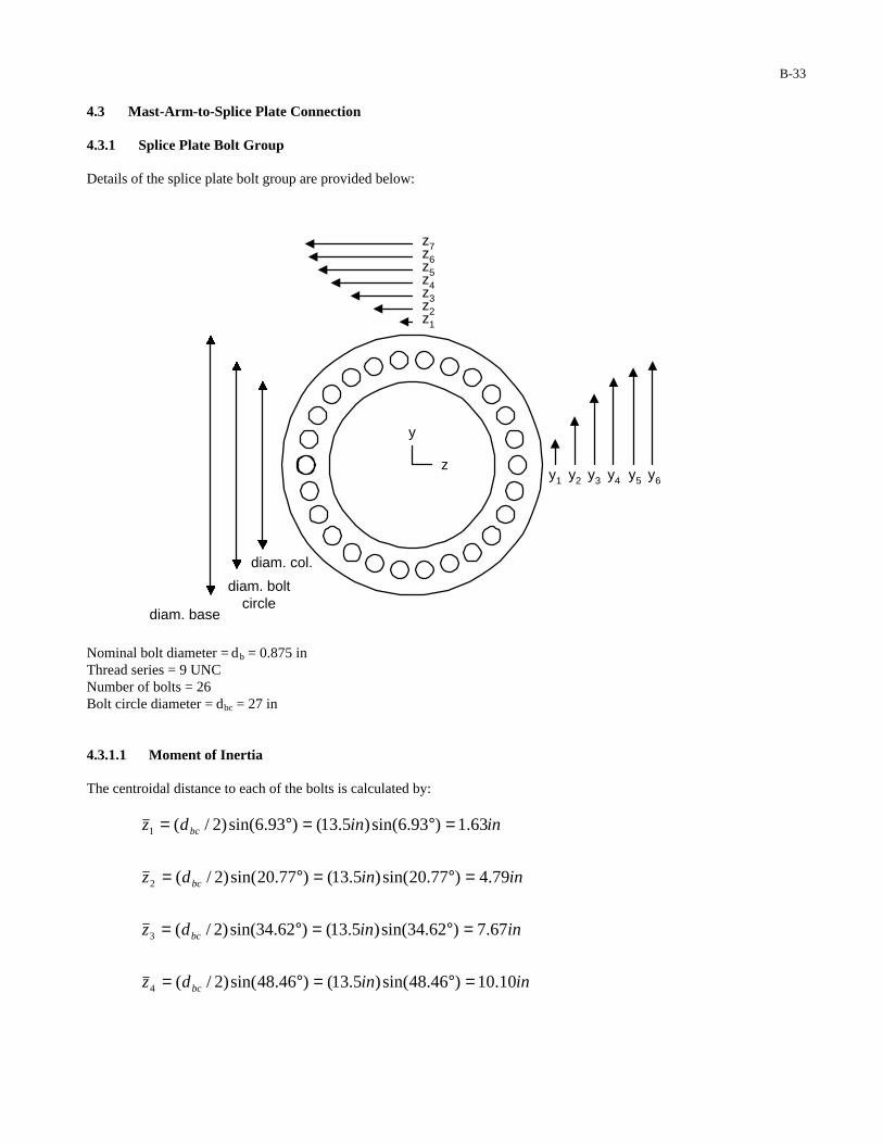
4.3 Mast-Arm-to-Splice Plate Connection 4.3.1 Splice Plate Bolt Group Details of the splice plate bolt group are provided below:
z7z6z5z4z3z2z1
y1 y2 y3 y4 y5 y6
diam. base
diam. boltcircle
diam. col.
y
z
Nominal bolt diameter = db = 0.875 in Thread series = 9 UNC Number of bolts = 26 Bolt circle diameter = dbc = 27 in 4.3.1.1 Moment of Inertia The centroidal distance to each of the bolts is calculated by:
inindz
inindz
inindz
inindz
bc
bc
bc
bc
10.10)46.48sin()5.13()46.48sin()2/(
67.7)62.34sin()5.13()62.34sin()2/(
79.4)77.20sin()5.13()77.20sin()2/(
63.1)93.6sin()5.13()93.6sin()2/(
4
3
2
1
=°=°=
=°=°=
=°=°=
=°=°=

B-34
inindy
inindy
inindy
inindy
inindy
inindy
inindz
inindz
inindz
bc
bc
bc
bc
bc
bc
bc
bc
bc
40.13)08.83sin()5.13()08.83sin()2/(
62.12)23.69sin()5.13()23.69sin()2/(
11.11)38.55sin()5.13()38.55sin()2/(
95.8)54.41sin()5.13()54.41sin()2/(
27.6)69.27sin()5.13()69.27sin()2/(
23.3)85.13sin()5.13()85.13sin()2/(
5.132/27)2/(
11.13)15.76sin()5.13()15.76sin()2/(
95.11)31.62sin()5.13()31.62sin()2/(
6
5
4
3
2
1
7
6
5
=°=°=
=°=°=
=°=°=
=°=°=
=°=°=
=°=°=
===
=°=°=
=°=°=
The tensile stress area of each bolt is calculated using Equation 5-23:
222, 462.0)]9/9743.0(875.0)[4/()]/9743.0()[4/( ininndA bbT =−=−= ππ
The moment of inertia of the bolt group about the z-axis is calculated by:
])[(4 26
25
24
23
22
21,
2,, yyyyyyAyAI bTbTzb +++++=∑=
4
222
2222
1094
])40.13()62.12()11.11(
)95.8()27.6()23.3)[(462.0(4
in
ininin
inininin
=+++
++=
))((2])[(4 27,
26
25
24
23
22
21,
2,, zAzzzzzzAzAI bTbTbTyb ++++++=∑=
4
22222
2222
1094
)5.13)(462.0(2])11.13()95.11()10.10(
)67.7()79.4()63.1)[(462.0(4
in
ininininin
inininin
=
++++
++=
The moment of inertia of a bolt group can also be more simply calculated using the “ring” formula:
( ) 4222,,, 10958/27)462.0(268/ ininindAII bcbTybzb ==∑==
B-35
4.3.1.2 Splice Plate Bolt Stress Range Based upon the calculations of Section 3, the splice-plate bolt group must be checked with respect to truck gusts about the z-axis and natural wind about the y-axis. The splice - plate-bolt stress range due to truck gusts is calculated by:
4,,,, 1094/)5.13)(9.876(/)2/()( inininkIdMS zbbcspliceTGzzboltR −==
ksi82.10= The splice-plate bolt stress range due to natural wind is calculated by:
4,,,, 1094/)5.13)(0.219(/)2/()( inininkIdMS ybbcspliceNWyyboltR −==
ksi70.2= Splice bolts are classified as Category D fatigue details (Detail 5 in Table 11-2). The constant amplitude fatigue limit corresponding to Category D is 7ksi (Table 11-3). Since the calculated stress range (10.82ksi) is greater than the constant amplitude fatigue limit (7ksi), the splice-plate bolt group is inadequately designed for fatigue. Potential Redesigns: 1. Assuming: (1) the number of bolts remains 26, (2) a 9UNC thread series is still used, and (3) the bolt circle diameter remains 27 inches, the connection will be adequately designed for fatigue using a bolt diameter of 1.125 inches. 2. Assuming: (1) the number of bolts remains 26, (2) a 9UNC thread series is still used, and (3) the bolt diameter remains 0.875 inches, the connection will be adequately designed for fatigue using a bolt circle diameter of 42 inches. 3. Assuming: (1) the number of bolts remains 26 and (2) a 9UNC thread series is still used, the connection will be adequately designed for fatigue using a bolt diameter of 1 inch and a bolt circle diameter of 31 inches. 4.3.2 Mast-Arm-to-Splice Plate Connection Details of the mast-arm to splice plate connection are provided below: Mast-arm diameter = db = 24 in Mast-arm thickness = t = 0.375 in 4.3.2.1 Moment of Inertia The moment of inertia of the mast-arm is calculated by:
])75.024()24)[(64/(]))(2()[64/( 4444 ininintddI armarmarm −−=−−= ππ
41942in=
B-36
4.3.2.2 Stress Range at Mast-Arm to Splice Plate Connection Since the moments of inertia of the mast-arm about the x and z-axes are equal, only the largest moment (MZ,TG,splice) needs to be checked. The stress range at the groove-welded mast-arm to splice plate connection, due to truck gusts, is calculated by:
4,,, 1942/)12)(9.876(/)2/()( inininkIdMS armarmspliceTGzzarmR −==
ksi42.5=
The mast-arm to splice plate connection (with backing ring attached with fillet or tack weld and left in place) is classified as a Category E’ fatigue detail (Detail 12 in Table 11-2). The constant amplitude fatigue limit for a Category E’ fatigue detail is 2.6ksi (Table 11-3). Since the calculated stress range (5.42ksi) is greater than the constant amplitude fatigue limit (2.6ksi), the mast-arm to splice plate connection is inadequately designed for fatigue. Potential Redesigns: 1. Assuming: (1) the fatigue resistance of the connection is not improved (i.e. a Category E’ groove-
welded mast-arm-to-baseplate connection with backing ring attached with fillet or tack weld and left in place (Detail 11 in Table 11-2) is used) and (2) the thickness of the mast-arm is not increased (i.e. t = 0.375 inches), the connection will be adequately designed for fatigue using a 37 inch mast-arm diameter.
2. Assuming: (1) the fatigue resistance of the connection is improved by attaching the backing ring with a
full-penetration weld (i.e. a Category E connection (Detail 12 in Table 11-2) is used) and (2) the thickness of the mast-arm is not increased (i.e. t = 0.375 inches), the connection will be adequately designed for fatigue using a 28 inch mast-arm diameter.
3. Assuming: (1) the fatigue resistance of the connection is improved by attaching the backing ring with a
full-penetration weld (i.e. a Category E connection (Detail 12 in Table 11-2) is used) and (2) the thickness is increased to 0.5 inches (i.e. t = 0.5 inches), the connection will be adequately designed for fatigue using a mast-arm diameter of 25 inches.
5 DEFLECTION 5.1 Assumptions (1) The displacement range at the tip of the mast-arm is calculated using the superposition of the following
displacement components.
1∆ : Displacement range at the tip of the mast-arm due to the rotation of the column (assuming a
cantilever beam fixed at the base of the column) under application of the moment
baseTGzM ,, = 1465k-in.
2∆ : Displacement range at the tip of the mast-arm due to the deflection of the column-bend (assuming
a cantilever beam fixed at the base of the bend) under the application of the moment
baseTGzM ,, = 1465k-in.

B-37
3∆ : Displacement range at the tip of the mast-arm due to the rotation of the column-bend (assuming a
cantilever beam fixed at the base of the bend) under the application of the moment
baseTGzM ,, = 1465k-in.
4∆ : Displacement range at the tip of the mast-arm due to the deflection of the mast-arm (assuming a
cantilever beam fixed at the base of the mast-arm) under the application of armTGF , = 1.892kips.
5∆ : Displacement range at the tip of the mast-arm due to the deflection of the mast-arm (assuming a
cantilever beam fixed at the base of the mast-arm) under the application of signTGF , = 4.24kips.
5.2 Mast-Arm Displacement Range 1∆
The rotation of the column at the column-bend transition is calculated by:
colbaseTGzcol EILM /))(( 1,,=θ
radians
inksiftinftink
0051.0
)]2549)(29000/[()/12)(38.21)(1465( 4
=−=
The displacement range at the tip of the mast-arm due to the rotation of the column is calculated by:
)/12)(85.23)(0051.0()( 41 ftinftftradiansRLcol +=+=∆ θ
in93.1=
5.3 Mast-Arm Displacement Range 2∆
The displacement range at the tip of the mast-arm due to the deflection of the bend resulting from the truck-gust moment acting on the bend is calculated by:
)]2549)(29000/[()96)(1465(/))(( 422,,2 inksiininkEIRM colbaseTGz −==∆
in183.0= Here Mz,TG,base is conservatively used as the moment acting on the bend. In actuality, the moment acting on the bend varies from Mz,TG,base to Mz,TG,splice.
5.4 Mast-Arm Displacement Range 3∆
The rotation of the bend is calculated by:
colbaseTGzbend EIRM /)2/)(( ,, πθ =
radians
inksiftinftink
0030.0
)]2549)(29000/[()/12)(4)(1465( 4
=−= π
The displacement range at the tip of the mast-arm due to the rotation of the bend is calculated by:
B-38
)/12)(5.23)(0030.0()( 43 ftinftradiansLbend ==∆ θ
in846.0=
5.5 Mast-Arm Displacement Range 4∆
The displacement range at the tip of the mast-arm due to the truck gust load applied to the mast-arm is calculated by:
armarmTG EILLLF 6/))2/(3()2/)(( 442
4,4 −=∆
in
inksiftinftftftk
078.0
)]1942)(29000)(6/[()/12)(75.11)5.23(3()75.11)(892.1( 432
=−=
5.6 Mast-Arm Displacement Range 5∆
The displacement range at the tip of the mast-arm due to the truck gust load applied to the sign is calculated by:
armsignTG EILLLF 6/))(3())(( 542
5,5 −=∆
in
inksiftinftftftk
183.0
)]1942)(29000)(6/[()/12)(0.12)5.23(3()0.12)(237.4( 432
=−=
5.7 Total Mast-Arm Deflection Range total∆
The total displacement range at the tip of the mast-arm is obtained by superposition of each of the deflection quantities:
ininininintotal 183.0078.0846.0183.093.154321 ++++=∆+∆+∆+∆+∆=∆
in22.3= The allowable vertical-plane mast-arm displacement range is 8 inches (Section 11.8). The computed deflection range at the tip of the mast-arm (3.22 inches) is less than the allowable deflection range (8 inches). Therefore, the structure is adequately designed with respect to the deflection limit state.
B-39
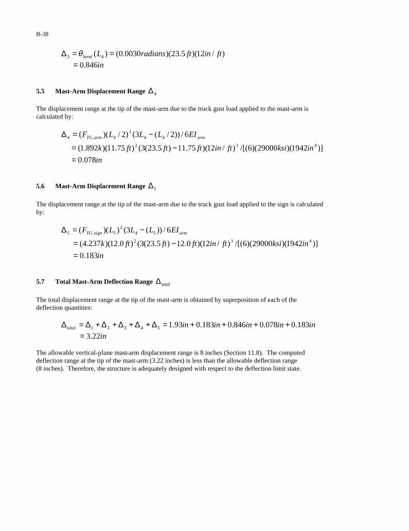
DESIGN EXAMPLE 3 1 GENERAL 1.1 Description
The structure is a cantilevered changeable (also known as variable) message sign (CMS or VMS) support structure (steel) composed of a uniform column and a four-chord truss mast-arm. The signal is to be designed for vibration and fatigue in accordance with Section 11 of the AASHTO specifications. It is assumed that the sign will be installed on a major highway and is therefore checked per the requirements for a Category I structure. Furthermore, it is assumed that the structure will be erected without approved vibration mitigation devices. All calculations are performed using U.S. Customary units.
L1
Hsign
z
y
x
L3
L2
L4
3.33 ft 3.83 ft 3.33 ft
4 @ 4.50 ft
Htruss
Wtruss
B-40
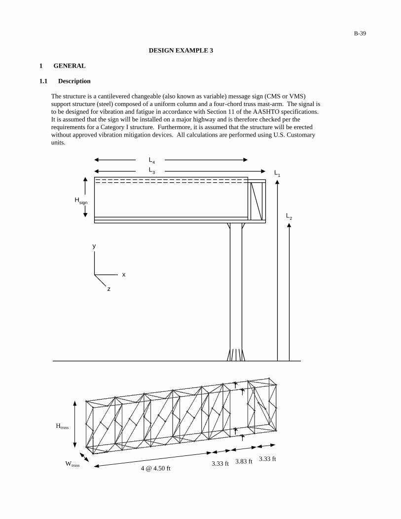
1.2 Dimensions Column: Column length = L1 = 31.12 ft Height to bottom of truss = L2 = 23.95 ft Height from bottom of upper stiffener to top of upper chord = Hst,upper = 13 in Height from bottom of lower stiffener to bottom of lower chord = Hst,upper = 14 in Diameter at base = db,col = 2 ft Thickness = t = 0.5 in Truss: Length of truss chords = L3 = 28.5 ft Cross-sectional area of truss chords = 5.75 in2
Height of truss = Htruss = 7.167 ft Width of truss = Wtruss = 3.083ft Sign: Length of sign = L4 = 25.5 ft (sign slightly overhangs truss) Height of sign = Hsign = 6.75 ft Width of sign = Wsign = 1.33 ft Anchor Rods: Nominal anchor rod diameter = dar = 2.5 in Stress area = AT,ar = 4.00 in2
Thread series = 4 UNC Number of anchor rods = 12 Anchor rod circle diameter = darc = 33 in
upper chord
upper plate
stiffener
collar
HS bolt
column wall
lower chord
lower chord plate
lower stiffener plate
HS bolt
stiffener
Htruss
Hst upper
Hst lower

B-41
1.3 Critical Fatigue Details The structure contains the following details, which must be designed for fatigue: 1. Anchor rods (Detail 5 in Table 11-2) 2. Column-to-baseplate groove-welded connection, with backing ring attached with fillet or tack weld and
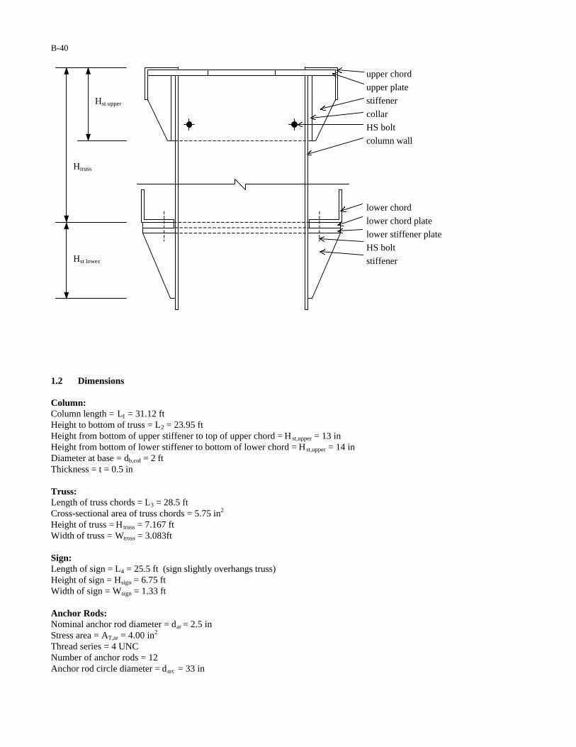
left in place, (Detail 12 in Table 11-2) 3. Groove-welded stiffener at column-base (Details 21 and 23 in Table 11-2) 4. Upper and lower-plate-juncture connections (Details 15 and 20 in Table 11-2) 5. Truss member-to-member fillet-welded connections (Detail 14 in Table 11-2) 2 CALCULATION OF LIMIT STATES FATIGUE LOADS Note: Visual Analysis software is used to analyze the four-chord truss. Static and shear loads are applied to the truss chords as tributary forces. The loads are distributed over the truss chords in a way that attempts to replicate actual loadings. Reaction forces in nodes at the upper- and lower-plate-junctures are used to find bending moments in the column. Member forces in the chords are used to find connection stresses. 2.1 Galloping As per the requirements of Section 11.7.1, galloping need not be considered in the design of four-chord truss cantilever supports for vibration and fatigue. 2.2 Vortex Shedding As per the requirements of Section 11.7.2, vortex shedding need not be considered in the design of cantilevered sign support structures for vibration and fatigue. 2.3 Natural Wind Gusts It is assumed that the sign will be erected at a location where the yearly mean wind velocity is 11mph. Therefore, Equation 11-5 is applied without modification: The equivalent static pressure range to be applied to the structure is calculated in accordance with: PNW = 5.2Cd(IF) = 5.2Cd(1.0) = 5.2Cd psf
Where IF = 1.0 (Table 11-1) is the importance factor used in the design of Category I sign support structures for natural wind. The equivalent static load range to be applied to the sign is calculated by: FNW,sign = (PNW)(Hsign)(L4) = (5.2 psf)(1.7)(6.75 ft)(25.5 ft) = 1522 lbs = 1.52 kips Where Cd = 1.7 is the currently recommended drag coefficient for a variable message sign (Table 3-5). The equivalent static load ranges to be applied to the exposed truss members are calculated by:
FNW,lowerchord = (PNW)(0.5 ft)(L3) = (5.2 psf)(2.0)(0.5 ft)(28.5 ft) = 148.2 lbs
FNW,upperchord = (PNW)(0.5 ft)(3.33 ft) = (5.2 psf)(2.0)(0.5 ft)(3.33 ft) = 17.3 lbs
B-42
FNW,vertical = (PNW)(0.25ft)(Htruss) = (5.2 psf)(2.0)(0.25 ft)(7.167ft) = 18.63 lbs FNW,diagonal = (PNW)(0.25ft)[(3.33 ft)2 + (Htruss)
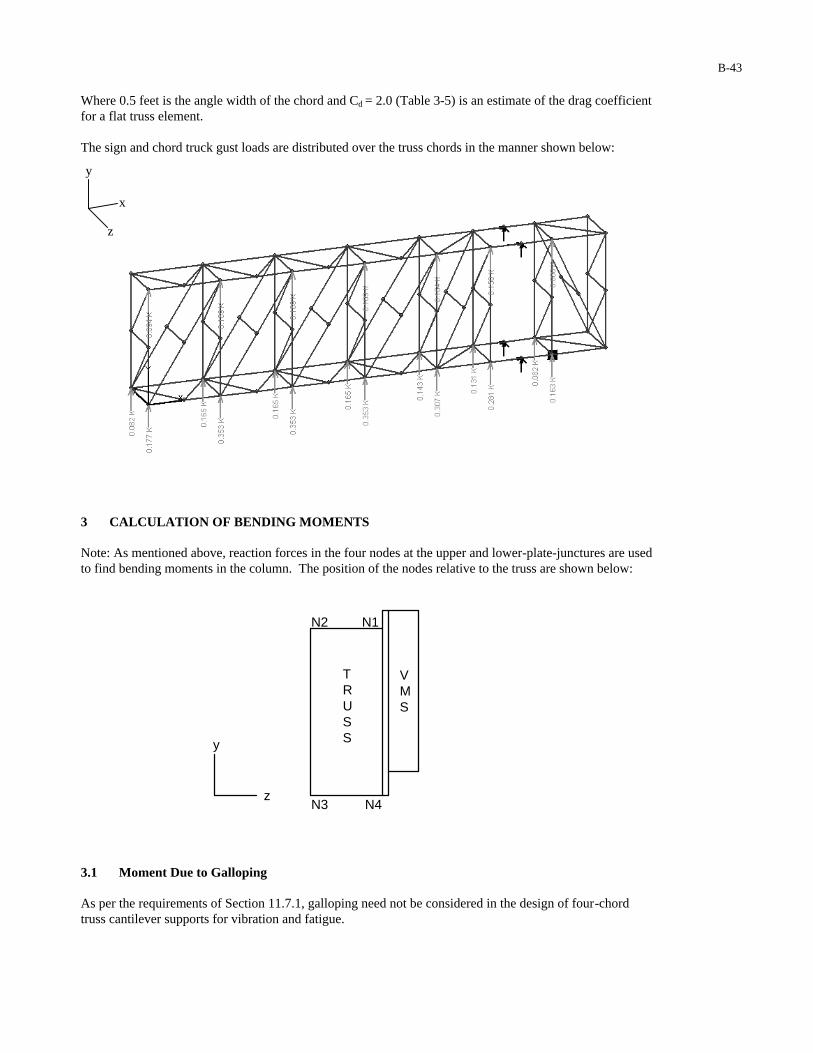
2] = (5.2 psf)(2.0)(0.25 ft)(7.903ft) = 20.55 lbs Where 0.5 ft is the angle width of the chords, 0.25 ft is the angle width of the vertical and diagonal members, and Cd = 2.0 (Table 3 -5) is the drag coefficient for a flat truss element. The sign and chord natural wind loads are distributed over the truss chords in the manner shown below:
The equivalent static load range to be applied to the column is calculated by: FNW,column = (PNW)(dcol)(L2) = (5.2 psf)(1.1)(2 ft)(23.95 ft) = 274.0 lbs Where Cd = 1.1 (Table 3 -5) is a conservative estimate of the drag coefficient for a circular cylinder. 2.4 Truck Gusts It is assumed that the sign will be erected at a location where the posted speed limit is not significantly less than 65 mph. Therefore, Equation 11-6 is applied without modification: The equivalent static pressure range to be applied to the structure is calculated in accordance with: PTG = 36.6Cd(IF) = 36.6Cd(1.0) = 36.6Cd psf Where IF = 1.0 (Table 11-1) is the importance factor used in the design of Category I sign support structures for truck gusts. The equivalent static load range to be applied to the sign is calculated by: FTG,sign = (PTG)(Wsign)(L4) = (36.6 psf)(1.7)(1.33 ft)(25.5 ft) = 2110 lbs = 2.110 kips
Where Cd = 1.7 (Table 3 -5) is the current recommended drag coefficient for a variable message sign. The equivalent static load range to be applied to each of the lower chords is calculated by: FTG,chord = (PTG)(0.5ft)(L4) = (36.6 psf)(2.0)(0.5 ft)(25.5 ft) = 933.3 lbs = 0.933 kips
z
y
x
B-43
Where 0.5 feet is the angle width of the chord and C = 2.0 (Table 3-5) is an estimate of the drag coefficient d
for a flat truss element. The sign and chord truck gust loads are distributed over the truss chords in the manner shown below:
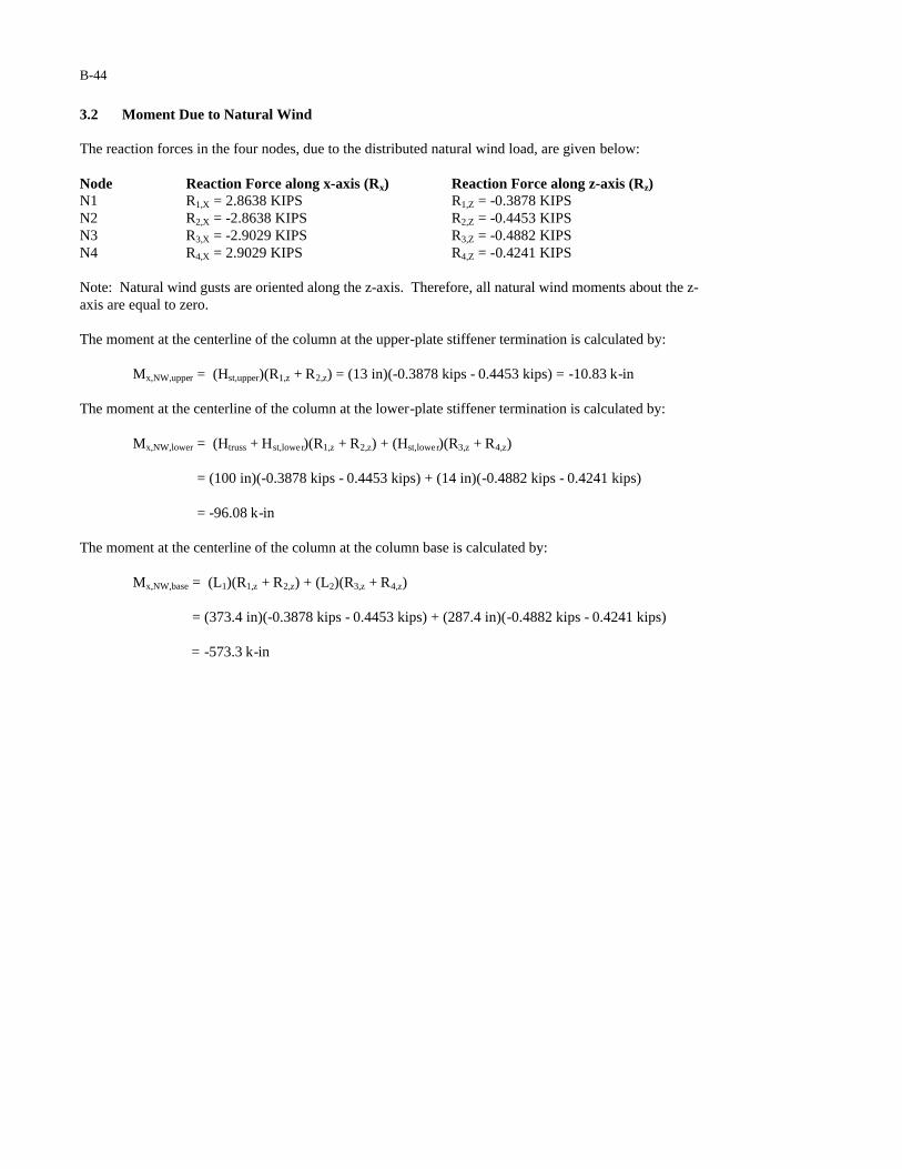
3 CALCULATION OF BENDING MOMENTS Note: As mentioned above, reaction forces in the four nodes at the upper and lower-plate-junctures are used to find bending moments in the column. The position of the nodes relative to the truss are shown below:
VMS
N1N2
N3 N4z
y
TRUSS
3.1 Moment Due to Galloping As per the requirements of Section 11.7.1, galloping need not be considered in the design of four-chord truss cantilever supports for vibration and fatigue.
z
y
x
B-44
3.2 Moment Due to Natural Wind The reaction forces in the four nodes, due to the distributed natural wind load, are given below: Node Reaction Force along x-axis (Rx) Reaction Force along z-axis (Rz) N1 R1,X = 2.8638 KIPS R1,Z = -0.3878 KIPS N2 R2,X = -2.8638 KIPS R2,Z = -0.4453 KIPS N3 R3,X = -2.9029 KIPS R3,Z = -0.4882 KIPS N4 R4,X = 2.9029 KIPS R4,Z = -0.4241 KIPS Note: Natural wind gusts are oriented along the z-axis. Therefore, all natural wind moments about the z-axis are equal to zero. The moment at the centerline of the column at the upper-plate stiffener termination is calculated by:
Mx,NW,upper = (Hst,upper)(R1,z + R2,z) = (13 in)(-0.3878 kips - 0.4453 kips) = -10.83 k-in
The moment at the centerline of the column at the lower-plate stiffener termination is calculated by:
Mx,NW,lower = (Htruss + Hst,lower)(R1,z + R2,z) + (Hst,lower)(R3,z + R4,z)
= (100 in)(-0.3878 kips - 0.4453 kips) + (14 in)(-0.4882 kips - 0.4241 kips) = -96.08 k-in
The moment at the centerline of the column at the column base is calculated by:
Mx,NW,base = (L1)(R1,z + R2,z) + (L2)(R3,z + R4,z)
= (373.4 in)(-0.3878 kips - 0.4453 kips) + (287.4 in)(-0.4882 kips - 0.4241 kips)
= -573.3 k-in

B-45
3.3 Moment Due to Truck Gusts The reaction forces in the four nodes, due to the distributed truck gust load, are given below: Node Reaction Force along x-axis (Rx) Reaction Force along z-axis (Rz) N1 R1,X = -2.3748 KIPS R1,Z = -0.1720 KIPS N2 R2,X = -3.4994 KIPS R2,Z = -0.2088 KIPS N3 R3,X = 3.4994 KIPS R3,Z = 0.2178 KIPS N4 R4,X = 2.3748 KIPS R4,Z = 0.1630 KIPS The moments at the centerline of the column at the upper-plate stiffener termination are calculated by:
Mx,TG,upper = (Hst,upper)(R1,z + R2,z) = (13 in)(-0.1720 kips - 0.2088 kips) = -4.95 k-in
Mz,TG,upper = (Hst,upper)(R1,x + R2,x) = (13 in)(-2.3748 kips - 3.4994 kips) = -76.36 k-in The moments at the centerline of the column at the lower-plate stiffener termination are calculated by:
Mx,TG,lower = (Htruss + Hst,lower)(R1,z + R2,z) + (Hst,lower)(R3,z + R4,z)
= (100 in)( -0.1720 kips - 0.2088 kips) + (14 in)(0.2178 kips + 0.1630 kips) = -32.75 k-in
Mz,TG,lower = (Htruss + Hst,lower)(R1,x + R2,x) + (Hst,lower)(R3,x + R4,x)
= (100 in)(-2.3748 kips - 3.4994 kips) + (14 in)(3.4994 kips + 2.3748 kips) = -505.2 k-in
The moments at the centerline of the column at the column base are calculated by:
Mx,TG,base = (L1)(R1,z + R2,z) + (L2)(R3,z + R4,z)
= (373.4 in)(-0.1720 kips - 0.2088 kips) + (287.4 in)(0.2178 kips + 0.1630 kips)
= -32.75 k-in
Mz,TG,base = (L1)(R1,x + R2,x) + (L2)(R3,x + R4,x)
= (373.4 in)(-2.3748 kips - 3.4994 kips) + (287.4 in)(3.4994 kips + 2.3748 kips) = -505.2 k-in
B-46
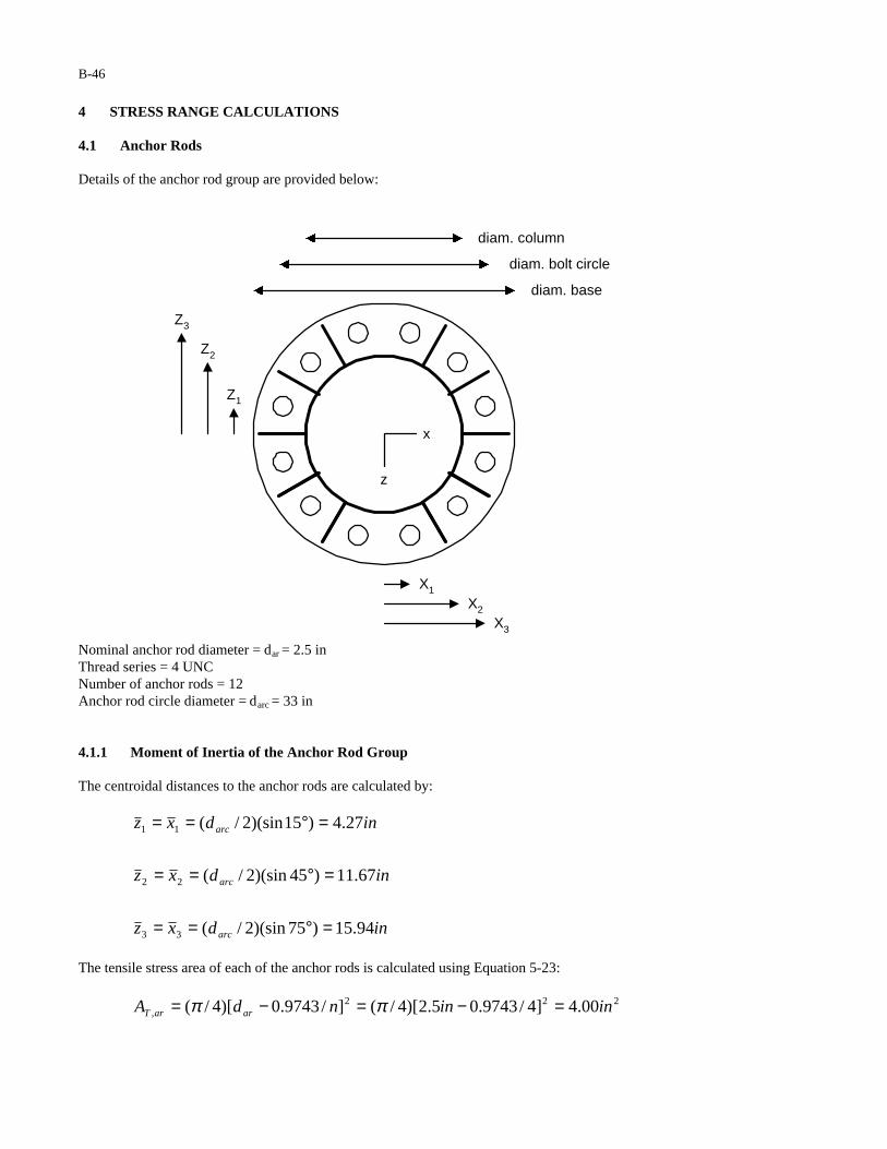
4 STRESS RANGE CALCULATIONS 4.1 Anchor Rods Details of the anchor rod group are provided below:
diam. base
diam. bolt circle
diam. column
X1
X2
X3
Z1
Z2
Z3
z
x
Nominal anchor rod diameter = dar = 2.5 in
Thread series = 4 UNC Number of anchor rods = 12 Anchor rod circle diameter = darc = 33 in 4.1.1 Moment of Inertia of the Anchor Rod Group The centroidal distances to the anchor rods are calculated by:
indxz
indxz
indxz
arc
arc
arc
94.15)75)(sin2/(
67.11)45)(sin2/(
27.4)15)(sin2/(
33
22
11
=°==
=°==
=°==
The tensile stress area of each of the anchor rods is calculated using Equation 5-23:
222, 00.4]4/9743.05.2)[4/(]/9743.0)[4/( ininndA ararT =−=−= ππ

B-47
The moment of inertia of the anchor rod group (about the x and z-axes) is by:
])[)(4( 23
22
21,
2, zzzAzAI arTarTar ++=∑=
])94.15()67.11()27.4)[(00.4)(4( 2222 inininin ++=
46536in= 4.1.2 Anchor Rod Stress Range Since the moments of inertia of the anchor rod group about the x- and z-axes at the baseplate are equal, only the largest moment (Mx,NW,base) needs to be checked. The axial stress range in the extreme anchor rods due to this moment is calculated by: (SR) bolt,x = Mx,NW,base(darc/2)/Iar = (573.3 k -in)(33 in / 2)/(6536 in4) = 1.45 ksi Anchor rods are classified as Category D fatigue details (Detail 5 in Table 11-2). The constant amplitude fatigue limit corresponding to a Category D fatigue detail is 7 ksi (Table 11-3). Since the calculated stress range (1.45 ksi) is less than the constant amplitude fatigue limit (7 ksi), the anchor bolt group is adequately designed for fatigue. 4.2 Column-to-Baseplate Connection Details of the column-to-baseplate groove-welded connection are provided below:
diam. base
diam. bolt circle
diam. column
X1
X2
X3
Z1
Z2
z
x

B-48
Column diameter = dcol = 24 in Column thickness = t = 0.5 in Stiffener length = Lst = 26 in Stiffener width = wst = 6.94 in Distance to outer edge of stiffener = rst,out = (rcol + wst) = 18.94 in Stiffener thickness = t st = 0.625 in Number of stiffeners = 10 4.2.1 Moment of Inertia The moment of inertia of the column is calculated by:
])124()24)[(64/(])2()[64/( 4444 ininintddI colcolcol −−=−−= ππ
42549in=
The area of each of the stiffeners at the column base is calculated by:
234.4)625.0)(94.6())(( ininintwA ststst ===
The radius to the centroid of the stiffener, at the baseplate, is calculated by:
inininwdr stcolst 47.15)2/94.6()2/24()2/()2/( =+=+=
The centroidal distance to each of the stiffeners is calculated by:
inrx
inrxz
inrxz
st
st
st
47.15
40.13)60(sin
74.7)30(sin
3
22
11
==
=°==
=°==
The moment of inertia at the column base (about the z-axis) is calculated by:
))((2])[(4 23
22
21
2, xAxxAIxAII ststcolstcolzcb +++=∑+=
222224 )47.15)(34.4(2])40.13()74.7)[(34.4(42549 ininininin +++=
48783in=
The moment of inertia at the column base (about the x-axis) is calculated by:
])[(4 22
21
2, zzAIzAII stcolstcolxcb ++=∑+=
])40.13()74.7)[(34.4(42549 2224 inininin ++=
46706in=

B-49
Note that the individual moment of inertia of each of the stiffeners is neglected in the calculation of the moment of inertia of the column base. 4.2.2 Stress Range at Column-to-Baseplate Connection Based upon the calculations of Section 3, the groove-welded column-to-baseplate connection must be checked with respect to truck gusts about the z-axis and natural wind about the x-axis. The stress range, due to truck gusts, of the groove-welded column-to-baseplate connection is calculated by:
4,,,, 8783/)2/24)(2.505(/)2/()( inininkIdMS zcbcolbaseTGzzcolR −==
ksi69.0= The stress range, due to natural wind, of the groove-welded column-to-baseplate connection is calculated by:
4,,,, 6706/)2/24)(3.573(/)2/()( inininkIdMS xcbcolbaseNWxxcolR −==
ksi03.1= The groove-welded column-to-baseplate connection (backing ring attached with fillet or tack weld and left in place) is classified as a Category E’ fatigue detail (Detail 12 in Table 11-2). The constant amplitude fatigue limit corresponding to Category E’ is 2.6 ksi (Table 11-3). Since the calculated stress range (1.03 ksi) is less than the constant amplitude fatigue limit (2.6 ksi), the column-to-baseplate connection is adequately designed for fatigue. 4.2.3 Stress Range at Stiffener-to-Baseplate Connection Based upon the calculations of Section 3, the stiffener-to-baseplate connection must be checked with respect to truck gusts about the z-axis and natural wind about the x-axis. The stress range, due to truck gusts, of the stiffener-to-baseplate connection is calculated by:
4
,,,,, /)()( zcboutstbaseTGzzcolR IrMS =
48783/)94.18)(2.505( ininink −=
ksi09.1= The stress range of the stiffener-to-baseplate connection, due to natural wind, is calculated by:
xcboutstbaseNWxxcolR IrMS ,,,,, /)60)(sin()( °=
ksi
ininink
40.1
)6706/)60)(sin94.18)(3.573( 4
=°−=
The stiffener-to-baseplate connection is a transverse load-bearing groove-welded attachment. Because a full-penetration weld is used instead of a fillet weld, the thickness limitations for Detail 23 of Table 11-2 do not apply. The connection is Category C regardless of the thickness of the stiffener. The constant amplitude fatigue limit corresponding to Category C is 10.0 ksi (Table 11-3). Since the calculated stress range (1.40 ksi) is less than the constant amplitude fatigue limit (10.0 ksi), the stiffener-to-baseplate connection is adequately designed for fatigue.
B-50
4.2.4 Stress Range at Termination of Stiffener Based upon the calculations of Section 3, the stiffener-to-column connection must be checked with respect to truck gusts about the z-axis and natural wind about the x-axis. The stress range at the termination of the stiffener, due to truck gusts, is calculated by:
2.38ksi
2549/)2/24)(2.505(
/)2/()(4
,,,
=−=
=
ininink
IdMS colcolbaseTGzzcolR
The stress range at the termination of the stiffener, due to natural wind, is calculated by:
2.34ksi
2549/)60)(sin2/24)(3.573(
/)60)(sin2/()(4
,,,
=°−=
°=
ininink
IdMS colcolbaseNWxxcolR
Where Mx,NW, base, is a conservative estimate of the bending moment at the stiffener termination. The weld termination at the end of the stiffener is classified as a Category C fatigue detail (Detail 21with
°=15α in Table 11-2). The constant amplitude fatigue limit corresponding to Category C is 10.0 ksi (Table 11-3). Since the calculated stress range (2.38 ksi) is less than the constant amplitude fatigue limit (10.0 ksi), the weld termination at the end of the stiffener is adequately designed for fatigue.
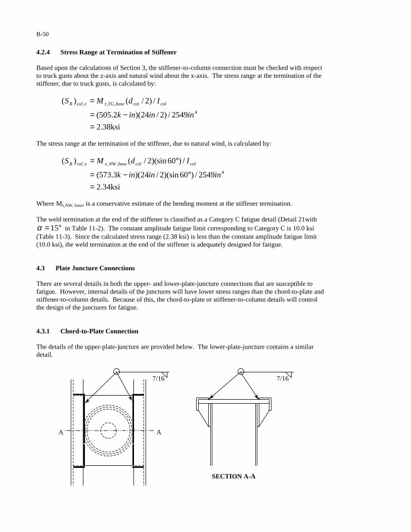
4.3 Plate Juncture Connections There are several details in both the upper- and lower-plate-juncture connections that are susceptible to fatigue. However, internal details of the junctures will have lower stress ranges than the chord-to-plate and stiffener-to-column details. Because of this, the chord-to-plate or stiffener-to-column details will control the design of the junctures for fatigue. 4.3.1 Chord-to-Plate Connection The details of the upper-plate-juncture are provided below. The lower-plate-juncture contains a similar detail.
7/16
A A
7/16
SECTION A-A
B-51
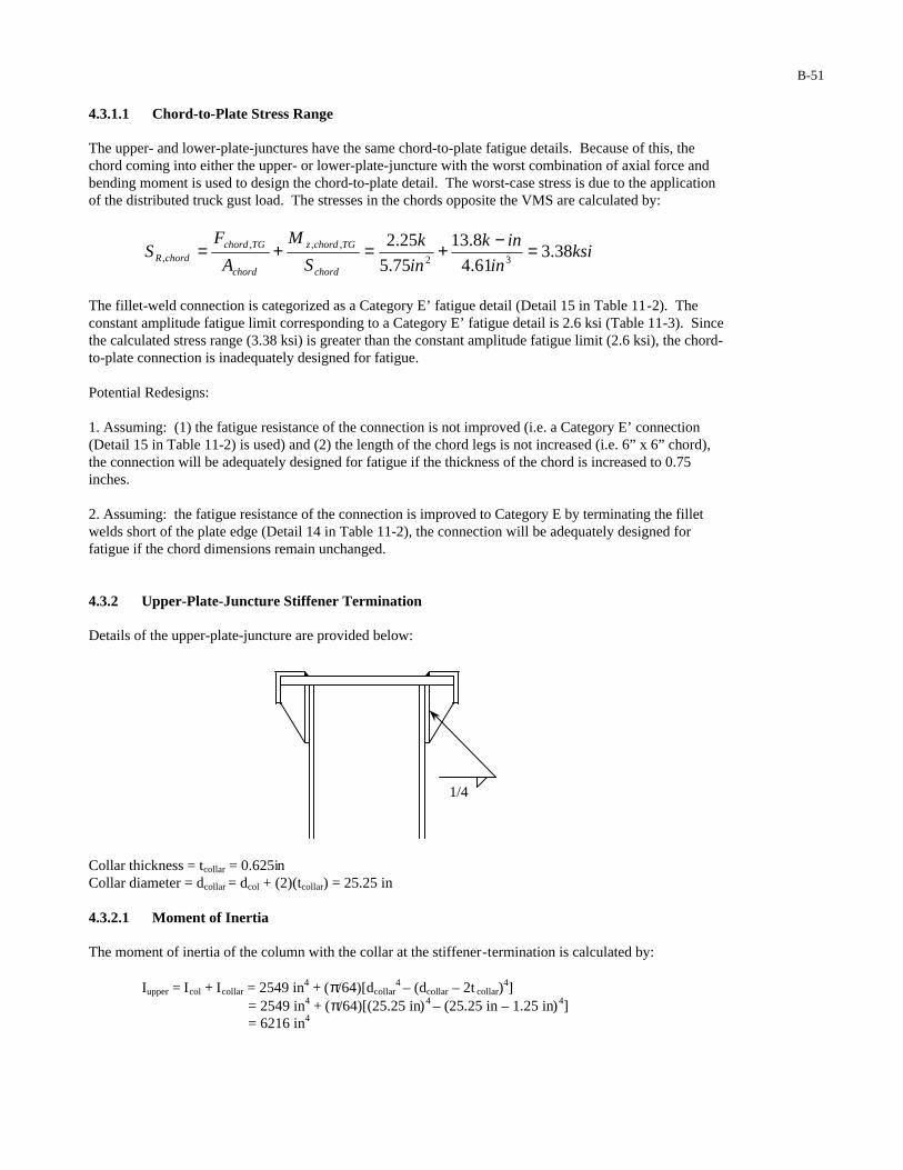
4.3.1.1 Chord-to-Plate Stress Range The upper- and lower-plate-junctures have the same chord-to-plate fatigue details. Because of this, the chord coming into either the upper- or lower-plate-juncture with the worst combination of axial force and bending moment is used to design the chord-to-plate detail. The worst-case stress is due to the application of the distributed truck gust load. The stresses in the chords opposite the VMS are calculated by:
ksiin
ink
in
k
S
M
A
FS
chord
TGchordz
chord
TGchordchordR 38.3
61.4
8.13
75.5
25.232
,,,, =−+=+=
The fillet-weld connection is categorized as a Category E’ fatigue detail (Detail 15 in Table 11-2). The constant amplitude fatigue limit corresponding to a Category E’ fatigue detail is 2.6 ksi (Table 11-3). Since the calculated stress range (3.38 ksi) is greater than the constant amplitude fatigue limit (2.6 ksi), the chord-to-plate connection is inadequately designed for fatigue. Potential Redesigns: 1. Assuming: (1) the fatigue resistance of the connection is not improved (i.e. a Category E’ connection (Detail 15 in Table 11-2) is used) and (2) the length of the chord legs is not increased (i.e. 6” x 6” chord), the connection will be adequately designed for fatigue if the thickness of the chord is increased to 0.75 inches. 2. Assuming: the fatigue resistance of the connection is improved to Category E by terminating the fillet welds short of the plate edge (Detail 14 in Table 11-2), the connection will be adequately designed for fatigue if the chord dimensions remain unchanged. 4.3.2 Upper-Plate-Juncture Stiffener Termination Details of the upper-plate-juncture are provided below:
Collar thickness = tcollar = 0.625in Collar diameter = dcollar = dcol + (2)(tcollar) = 25.25 in 4.3.2.1 Moment of Inertia The moment of inertia of the column with the collar at the stiffener-termination is calculated by:
Iupper = Icol + Icollar = 2549 in4 + (π/64)[dcollar4 – (dcollar – 2t collar)
4] = 2549 in4 + (π/64)[(25.25 in)4 – (25.25 in – 1.25 in)4] = 6216 in4
1/4
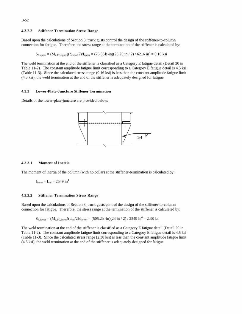
B-52
4.3.2.2 Stiffener Termination Stress Range Based upon the calculations of Section 3, truck gusts control the design of the stiffener-to-column connection for fatigue. Therefore, the stress range at the termination of the stiffener is calculated by: SR,upper = (Mz,TG,upper)(dcollar/2)/Iupper = (76.36 k -in)(25.25 in / 2) / 6216 in4 = 0.16 ksi The weld termination at the end of the stiffener is classified as a Category E fatigue detail (Detail 20 in Table 11-2). The constant amplitude fatigue limit corresponding to a Category E fatigue detail is 4.5 ksi (Table 11-3). Since the calculated stress range (0.16 ksi) is less than the constant amplitude fatigue limit (4.5 ksi), the weld termination at the end of the stiffener is adequately designed for fatigue. 4.3.3 Lower-Plate-Juncture Stiffener Termination Details of the lower-plate-juncture are provided below:
4.3.3.1 Moment of Inertia The moment of inertia of the column (with no collar) at the stiffener-termination is calculated by:
Ilower = Icol = 2549 in4 4.3.3.2 Stiffener Termination Stress Range Based upon the calculations of Section 3, truck gusts control the design of the stiffener-to-column connection for fatigue. Therefore, the stress range at the termination of the stiffener is calculated by: SR,lower = (Mz,TG,lower)(dcol/2)/Ilower = (505.2 k -in)(24 in / 2) / 2549 in4 = 2.38 ksi The weld termination at the end of the stiffener is classified as a Category E fatigue detail (Detail 20 in Table 11-2). The constant amplitude fatigue limit corresponding to a Category E fatigue detail is 4.5 ksi (Table 11-3). Since the calculated stress range (2.38 ksi) is less than the constant amplitude fatigue limit (4.5 ksi), the weld termination at the end of the stiffener is adequately designed for fatigue.
1/4

B-53
4.4 Truss Member Connection Stress Range The details of a typical member-to-member connection are given below:
Six different angle sizes are used in the truss. The greatest axial force for each angle size is used to determine the worst-case stress range for each angle size.
ksiin
ink
in
k
S
M
A
FS
chord
TGchordz
chord
TGchordchordR 38.3
61.4
8.13
75.5
25.232
,,,, =−+=+=
ksiin
ink
in
k
S
M
A
FS
vertical
TGvertical
vertical
TGverticalverticalR 16.3
577.0
82.0
44.1
51.232
,,, =−+=+=
ksiin
ink
in
k
S
M
A
FS
largebrace
largebrace,NW
largebrace
largebrace,NWlargebraceR 52.1
247.0
01.0
938.0
39.132, =−+=+=
ksiin
ink
in
k
S
M
A
FS
smallbrace
NWsmallbrace
smallbrace
NWsmallbracesmallbraceR 15.1
091.0
0
563.0
647.032
,,, =−+=+=
The fillet-weld member-to-member connections, with the weld terminating short of plate edge, are categorized as a Category E fatigue detail (Detail 14 in Table 11-2). The constant amplitude fatigue limit corresponding to a Category E fatigue detail is 4.5 ksi (Table 11-3). Since the maximum calculated stress range (3.38 ksi) is less than the constant amplitude fatigue limit (4.5 ksi), the member-to-member connections are adequately designed for fatigue. 5 DEFLECTION As per the requirements of Section 11.8, deflection need not be considered in the design of a cantilevered truss support structure for fatigue design.
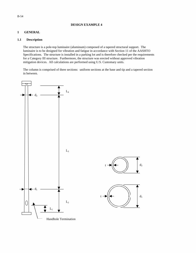
B-54
DESIGN EXAMPLE 4 1 GENERAL 1.1 Description
The structure is a pole-top luminaire (aluminum) composed of a tapered structural support. The luminaire is to be designed for vibration and fatigue in accordance with Section 11 of the AASHTO Specifications. The structure is installed in a parking lot and is therefore checked per the requirements for a Category III structure. Furthermore, the structure was erected without approved vibration mitigation devices. All calculations are performed using U.S. Customary units. The column is comprised of three sections: uniform sections at the base and tip and a tapered sectionin between.
Handhole Termination
L3
L4
L2
L1
t
t
d2
d1
d2
d1
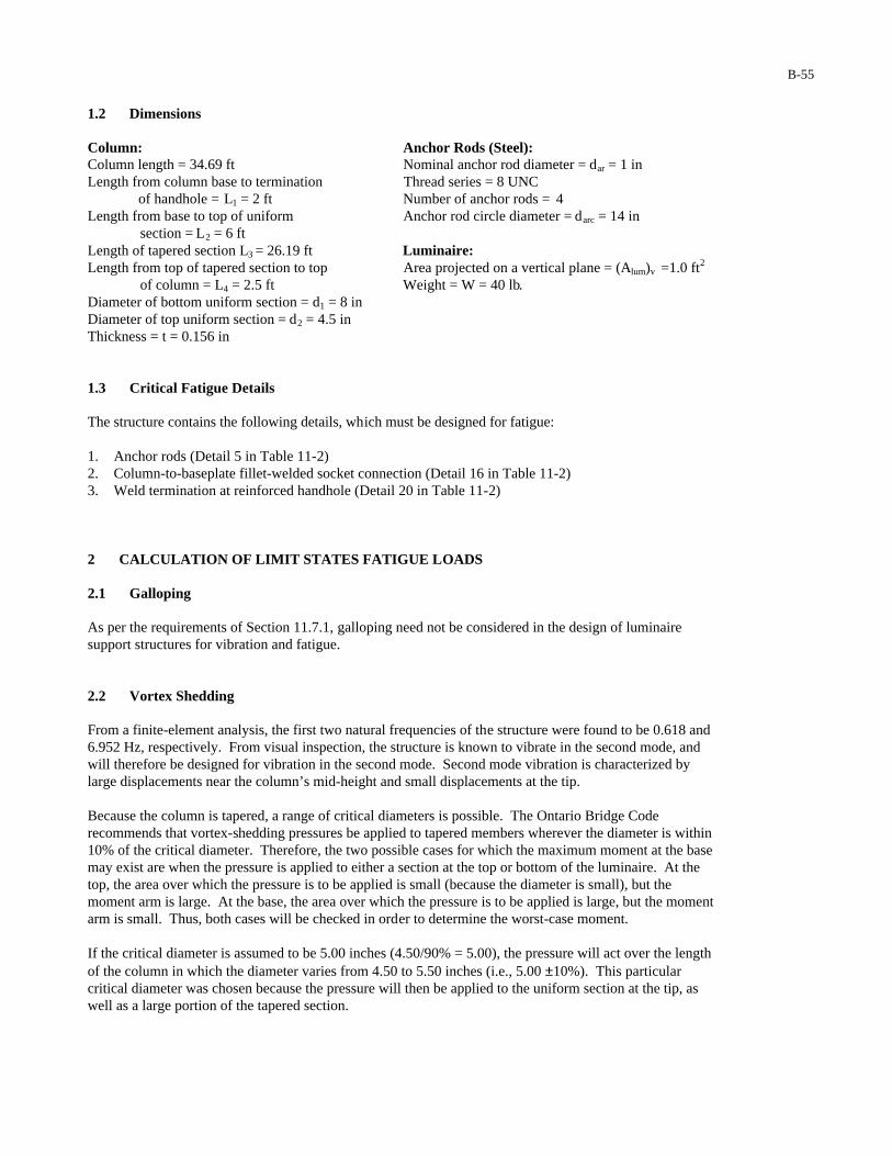
B-55
1.2 Dimensions Column: Anchor Rods (Steel): Column length = 34.69 ft Nominal anchor rod diameter = dar = 1 in Length from column base to termination Thread series = 8 UNC of handhole = L1 = 2 ft Number of anchor rods = 4 Length from base to top of uniform Anchor rod circle diameter = darc = 14 in section = L2 = 6 ft Length of tapered section L3 = 26.19 ft Luminaire: Length from top of tapered section to top Area projected on a vertical plane = (Alum)v =1.0 ft2
of column = L4 = 2.5 ft Weight = W = 40 lb. Diameter of bottom uniform section = d1 = 8 in Diameter of top uniform section = d2 = 4.5 in Thickness = t = 0.156 in 1.3 Critical Fatigue Details The structure contains the following details, which must be designed for fatigue: 1. Anchor rods (Detail 5 in Table 11-2) 2. Column-to-baseplate fillet-welded socket connection (Detail 16 in Table 11-2) 3. Weld termination at reinforced handhole (Detail 20 in Table 11-2) 2 CALCULATION OF LIMIT STATES FATIGUE LOADS 2.1 Galloping As per the requirements of Section 11.7.1, galloping need not be considered in the design of luminaire support structures for vibration and fatigue. 2.2 Vortex Shedding From a finite-element analysis, the first two natural frequencies of the structure were found to be 0.618 and 6.952 Hz, respectively. From visual inspection, the structure is known to vibrate in the second mode, and will therefore be designed for vibration in the second mode. Second mode vibration is characterized by large displacements near the column’s mid-height and small displacements at the tip. Because the column is tapered, a range of critical diameters is possible. The Ontario Bridge Code recommends that vortex-shedding pressures be applied to tapered members wherever the diameter is within 10% of the critical diameter. Therefore, the two possible cases for which the maximum moment at the base may exist are when the pressure is applied to either a section at the top or bottom of the luminaire. At the top, the area over which the pressure is to be applied is small (because the diameter is small), but the moment arm is large. At the base, the area over which the pressure is to be applied is large, but the moment arm is small. Thus, both cases will be checked in order to determine the worst-case moment. If the critical diameter is assumed to be 5.00 inches (4.50/90% = 5.00), the pressure will act over the length of the column in which the diameter varies from 4.50 to 5.50 inches (i.e., 5.00 ±10%). This particular critical diameter was chosen because the pressure will then be applied to the uniform section at the tip, as well as a large portion of the tapered section.
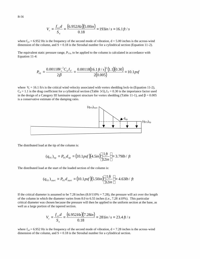
B-56
( )( )sftsin
inHz
S
dfV
n
nc /1.16/193
18.0
00.5952.62 ====
where fn2 = 6.952 Hz is the frequency of the second mode of vibration, d = 5.00 inches is the across-wind dimension of the column, and S = 0.18 is the Strouhal number for a cylindrical section (Equation 11-2). The equivalent static pressure range, PVS, to be applied to the column is calculated in accordance with Equation 11-4:
( ) ( )( )( ) psf
sftICVP Fdc
VS 1.10005.02
30.01.1/1.1600118.0
2
00118.0 22
===β
where Vc = 16.1 ft/s is the critical wind velocity associated with vortex shedding lock-in (Equation 11-2), Cd = 1.1 is the drag coefficient for a cylindrical section (Table 3-5), I F = 0.30 is the importance factor used in the design of a Category III luminaire support structure for vortex shedding (Table 11-1), and β = 0.005 is a conservative estimate of the damping ratio.
dtip
The distributed load at the tip of the column is:
( )( ) ftlbin
ftinpsfdPq tipVStipVS /79.3
12
15.41.10)( =
==
The distributed load at the start of the loaded section of the column is:
( )( ) ftlbin
ftinpsfdPq startVSstartVS /63.4
12
150.51.10)( =
==
If the critical diameter is assumed to be 7.28 inches (8.0/110% = 7.28), the pressure will act over the length of the column in which the diameter varies from 8.0 to 6.55 inches (i.e., 7.28 ±10%). This particular critical diameter was chosen because the pressure will then be applied to the uniform section at the base, as well as a large portion of the tapered section.
( )( )sftsin
inHz
S
dfV
n
nc /4.23/281
18.0
28.7952.62 ====
where fn2 = 6.952 Hz is the frequency of the second mode of vibration, d = 7.28 inches is the across-wind dimension of the column, and S = 0.18 is the Strouhal number for a cylindrical section.
(qVS)start
(qVS)tip
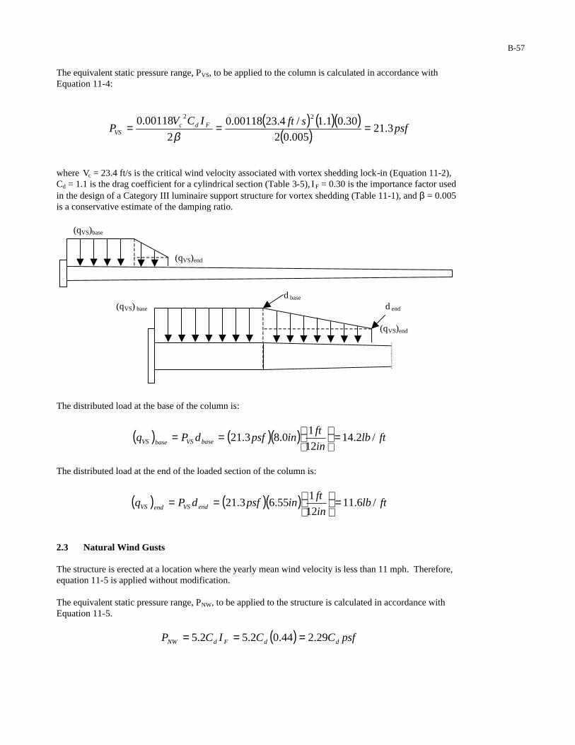
B-57
The equivalent static pressure range, PVS, to be applied to the column is calculated in accordance with Equation 11-4:
( ) ( )( )( ) psf
sftICVP Fdc
VS 3.21005.02
30.01.1/4.2300118.0
2
00118.0 22
===β
where Vc = 23.4 ft/s is the critical wind velocity associated with vortex shedding lock-in (Equation 11-2), Cd = 1.1 is the drag coefficient for a cylindrical section (Table 3-5), I F = 0.30 is the importance factor used in the design of a Category III luminaire support structure for vortex shedding (Table 11-1), and β = 0.005 is a conservative estimate of the damping ratio.
d base
(qVS) base d end
(qVS)end
The distributed load at the base of the column is:
( ) ( )( ) ftlbin
ftinpsfdPq baseVSbaseVS /2.14
12
10.83.21 =
==
The distributed load at the end of the loaded section of the column is:
( ) ( )( ) ftlbin
ftinpsfdPq endVSendVS /6.11
12
155.63.21 =
==
2.3 Natural Wind Gusts The structure is erected at a location where the yearly mean wind velocity is less than 11 mph. Therefore, equation 11-5 is applied without modification. The equivalent static pressure range, PNW, to be applied to the structure is calculated in accordance with Equation 11-5.
( ) psfCCICP ddFdNW 29.244.02.52.5 ===
(qVS)end
(qVS)base

B-58
Where IF = 0.44 (Table 11-1) is the importance factor used in the design of a Category III luminaire support structure for natural wind. The equivalent static load range to be applied to the entire column, (FNW)base,col, is calculated by:
( ) ( ) ( )( )[ ][ ] lbftAPF vcolNWcolbaseNW 9.466.181.129.2 21,, ===
where (Acol)v,1 is the area of the entire column projected on a vertical plane, and Cd = 1.1 is the drag coefficient for a cylindrical section (Table 3-5). The equivalent static load range to be applied to the column above the handhole, (FNW)handhole,col, is calculated by:
( ) ( ) ( )( )[ ][ ] lbftAPF vcolNWcolhandholeNW 3.432.171.129.2 22,, ===
where (Acol)v,2 is the area of the column above the handhole projected on a vertical plane, and Cd = 1.1 is the drag coefficient for a cylindrical section (Table 3-5). The equivalent static load range to be applied to the luminaire, (FNW)lum, is calculated by:
( ) ( ) ( )( )[ ] ( )[ ] lbftAPF vlumNWlumNW 75.212.129.2 2 ===
where (Alum)v = 1 ft2 is the area of the luminaire projected on a vertical plane and Cd = 1.2 is the drag coefficient for a luminaire with a rectangular flat side shape (Table 3-5).
2.4 Truck Gusts As per the requirements of Section 11.7.4, truck gusts need not be considered in the design of luminaire support structures for vibration and fatigue. 3 CALCULATION OF BENDING MOMENTS 3.1 Moment Due to Vortex Shedding 3.1.1 Moment Due to Vortex Shedding at Column Base The bending moment at the base of the column due to vortex shedding loading at the tip is calculated by:
(qVS)start (qVS)tip
ystart
( ) 21, MMM tipbaseVS +=
2
1
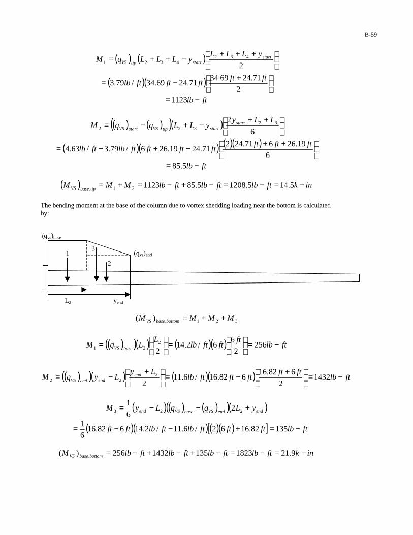
B-59
( ) ( )
+++
−++=2
4324321
startstarttipVS
yLLLyLLLqM
( )( )
+−=
2
71.2469.3471.2469.34/79.3
ftftftftftlb
ftlb −=1123
( ) ( )( )( )
++
−+−=6
2 32322
LLyyLLqqM start
starttipVSstartVS
( )( ) ( )( )
++−+−=
6
19.26671.24271.2419.266/79.3/63.4
ftftftftftftftlbftlb
ftlb −= 5.85
( ) inkftlbftlbftlbMMM tipbaseVS −=−=−+−=+= 5.145.12085.85112321,
The bending moment at the base of the column due to vortex shedding loading near the bottom is calculated by:
(qvs)base
(qvs)end
L2 yend
321,)( MMMM bottombaseVS ++=
( )( )( ) ( )( ) ftlbft
ftftlbL
LqM baseVS −=
=
= 256
2
66/2.14
22
21
( )( )( ) ( )( ) ftlbftft
ftftftlbLy
LyqM endendendVS −=
+−=
+
−= 14322
682.16682.16/6.11
22
22
( ) ( ) ( )( )( )endendVSbaseVSend yLqqLyM +−−= 223 26
1
( )( ) ( )( )[ ] ftlbftftftlbftlbftft −=+−−= 13582.1662/6.11/2.14682.166
1
inkftlbftlbftlbftlbM bottombaseVS −=−=−+−+−= 9.2118231351432256)( ,
1
2
3

B-60
Since 14.5 k-in is less than 21.9 k-in, applying the vortex shedding load near the bottom of the column controls for the vortex shedding moment at the base. 3.1.2 Moment Due to Vortex Shedding at Handhole The bending moment at the handhole due to vortex shedding loading at the tip is calculated by:
( ) 21, MMM tiphandholeVS +=
( ) ( )
−
+++−++= 1
4324321 2
LyLLL
yLLLqM startstarttipVS
( )( )
−+−= ft
ftftftftftlb 2
2
71.2469.3471.2469.34/79.3
ftlb −=1048
( ) ( )( )( )
−++
−+−=6
32 132322
LLLyyLLqqM start
starttipVSstartVS
( )( ) ( )( ) ( )( )
−++−+−=
6
2319.26671.24271.2419.266/79.3/63.4
ftftftftftftftftlbftlb
ftlb −= 2.79
( ) inkftlbftlbftlbMMM tiphandholeVS −=−=−+−=+= 5.132.11272.79104821,
The bending moment at the handhole due to vortex shedding loading near the bottom is calculated by:
321,)( MMMM bottomhandholeVS ++=
( )( )( ) ( )( ) ftlbftft
ftftftlbLL
LLqM baseVS −=
−−=
−
−= 1142
2626/2.14
212
121
( )( )( ) ( )( ) ftlbftftft
ftftftlbLLy
LyqM endendendVS −=
−+−=
−
+−= 11812
2
682.16682.16/6.11
2 12
22
( ) ( ) ( )( )( )1223 326
1LyLqqLyM endendVSbaseVSend −+−−=
( )( ) ( )( ) ( )( )[ ] ftlbftftftftlbftlbftft −=−+−−= 1072382.1662/6.11/2.14682.166
1
inkftlbftlbftlbftlbM bottomhandholeVS −=−=−+−+−= 8.1614021071181114)( ,
Since 13.5 k-in is less than 16.8 k-in, applying the vortex shedding load near the bottom of the pole also controls for the vortex shedding moment at the handhole.

B-61
3.2 Moment Due to Natural Wind Gusts 3.2.1 Moment Due to Natural Wind Gusts at Column Base The bending moment due to natural wind gusts at the base of the column is calculated by:
( ) )()()()( 4321, LLLFyFM lumNWcolbaseNWbaseNW +++=
( )( ) ( )( )ftlbftlb 69.3475.246.159.46 +=
inkftlb −=−= 85.9820
3.2.2 Moment Due to Natural Wind Gusts at Handhole The bending moment due to natural wind gusts at the handhole is calculated by:
( ) )()()()( 14322, LLLLFyFM lumNWcolhandholeNWhandholeNW −+++=
( )( ) ( )( )ftftlbftlb 269.3475.257.143.43 −+=
inkftlb −=−= 65.8721
4 STRESS RANGE CALCULATIONS 4.1 Anchor Rods Details of the anchor rod group are provided below: Nominal anchor rod diameter = dar = 1 in Thread series = 8 UNC Thread pitch = 0.125 in Number of anchor rods = 4 Anchor rod circle diameter = darc = 14 in 4.1.1 Moment of Inertia of the Anchor Rod Group The centroidal distance to each of the anchor rods, x , is calculated by:
( ) inind
x arc 95.445cos745cos2
=== oo
where darc = 14 inches is the diameter of the anchor rod circle. The tensile stress area of each of the anchor rods is calculated by:
222
606.08
9743.1
4
9743.
4inin
ndA arT =
−=
−= ππ
darc
dar
x
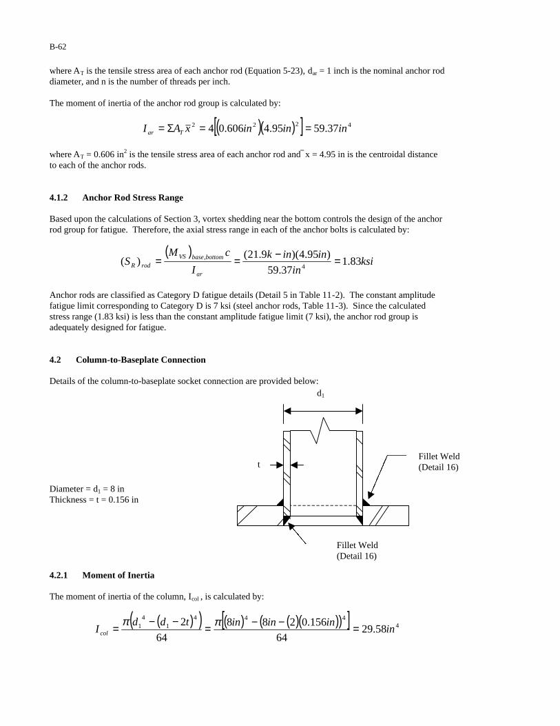
B-62
where AT is the tensile stress area of each anchor rod (Equation 5-23), dar = 1 inch is the nominal anchor rod diameter, and n is the number of threads per inch. The moment of inertia of the anchor rod group is calculated by:
( )( )[ ] 4222 37.5995.4606.04 inininxAI Tar ==Σ=
where AT = 0.606 in2 is the tensile stress area of each anchor rod and x = 4.95 in is the centroidal distance to each of the anchor rods. 4.1.2 Anchor Rod Stress Range Based upon the calculations of Section 3, vortex shedding near the bottom controls the design of the anchor rod group for fatigue. Therefore, the axial stress range in each of the anchor bolts is calculated by:
( )ksi
in
inink
I
cMS
ar
bottombaseVS
rodR 83.137.59
)95.4)(9.21()(
4
, =−==
Anchor rods are classified as Category D fatigue details (Detail 5 in Table 11-2). The constant amplitude fatigue limit corresponding to Category D is 7 ksi (steel anchor rods, Table 11-3). Since the calculated stress range (1.83 ksi) is less than the constant amplitude fatigue limit (7 ksi), the anchor rod group is adequately designed for fatigue. 4.2 Column-to-Baseplate Connection Details of the column-to-baseplate socket connection are provided below:
Diameter = d1 = 8 in Thickness = t = 0.156 in
4.2.1 Moment of Inertia The moment of inertia of the column, Icol , is calculated by:
( )( ) ( ) ( )( )( )[ ] 4444
14
1 58.2964
156.0288
64
2in
ininintddIcol =−−=
−−= ππ
Fillet Weld (Detail 16)
Fillet Weld (Detail 16)
d1
t
B-63
4.2.2 Column Stress Range Based upon the calculations of section 3, vortex shedding near the bottom of the column controls the design of the column-to-baseplate connection for fatigue. Therefore, the stress range at the column base is calculated by:
( ) ( ) ( )( )ksi
in
inink
I
cMS
col
bottombaseVS
colR 96.258.29
49.214
, =−==
The column-to-baseplate socket connection is classified as a Category E’ fatigue detail (Detail 16 in Table 11-2). The constant amplitude fatigue limit corresponding to Category E’ is 1.0 ksi for aluminum (Table 11-3). Since the calculated stress range (2.96 ksi) is greater than the constant amplitude fatigue limit (1.0 ksi), the socket connection is inadequately designed for fatigue. Potential Redesigns: 1. Assuming: (1) the fatigue resistance of the connection is not improved (i.e. a Category E’ socket
connection (Detail 16) is used) and (2) the thickness of the column is not increased (i.e. t = 0.156 in), the connection will be adequately designed for fatigue using a 13.625-inch column diameter.
2. Assuming: (1) the fatigue resistance of the connection is not improved (i.e. a Category E’ socket
connection (Detail 16) is used) and (2) the diameter of the column is not increased (i.e. d = 8 in), the connection will be adequately designed for fatigue using a column thickness equal to 0.533 in.
3. Assuming: (1) the fatigue resistance of the connection is improved to Category E (i.e. a Category E full
penetration connection (Detail 11) is used) and (2) the thickness of the column is not increased (i.e. t = 0.156 in), the connection will be adequately designed for fatigue using a 10-inch column diameter.
4. Assuming: (1) the fatigue resistance of the connection is improved to category E (i.e. a Category E
full-penetration connection (Detail 11) is used) and (2) the diameter of the column is not increased (i.e. d = 8 in), the connection will be adequately designed for fatigue using a column thickness equal to 0.25 in.
5. Assuming: (1) the fatigue resistance of the connection is improved to Category C (i.e. the column-to-
baseplate connection is fabricated with properly detailed stiffeners (Detail 21), and (2) the thickness of the column is not increased (i.e. t = 0.156 inches), the connection will be adequately designed for fatigue using a 7-inch column diameter.
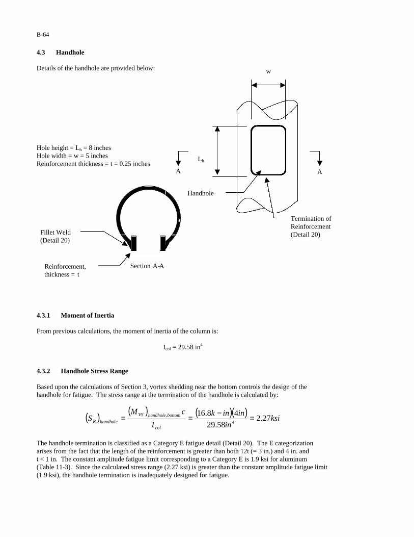
B-64
4.3 Handhole Details of the handhole are provided below:
Hole height = Lh = 8 inches Hole width = w = 5 inches Reinforcement thickness = t = 0.25 inches
4.3.1 Moment of Inertia From previous calculations, the moment of inertia of the column is:
Icol = 29.58 in4
4.3.2 Handhole Stress Range Based upon the calculations of Section 3, vortex shedding near the bottom controls the design of the handhole for fatigue. The stress range at the termination of the handhole is calculated by:
( ) ( ) ( )( )ksi
in
inink
I
cMS
col
bottomhandholeVS
handholeR 27.258.29
48.164
, =−==
The handhole termination is classified as a Category E fatigue detail (Detail 20). The E categorization arises from the fact that the length of the reinforcement is greater than both 12t (= 3 in.) and 4 in. and t < 1 in. The constant amplitude fatigue limit corresponding to a Category E is 1.9 ksi for aluminum (Table 11-3). Since the calculated stress range (2.27 ksi) is greater than the constant amplitude fatigue limit (1.9 ksi), the handhole termination is inadequately designed for fatigue.
Lh
w
Handhole
Termination of Reinforcement (Detail 20)
A A
Section A-A
Fillet Weld (Detail 20)
Reinforcement, thickness = t
B-65
Potential Redesigns: 1. Assuming: (1) the fatigue resistance of the connection is not improved (i.e. a Category E longitudinal
attachment (Detail 20) is used) and (2) the thickness of the column is not increased (i.e. t = 0.156 in), the connection will be adequately designed for fatigue using a 8.75-inch column diameter.
2. Assuming: (1) the fatigue resistance of the connection is not improved (i.e. a Category E longitudinal
attachment (Detail 20) is used) and (2) the diameter of the column is not increased (i.e. d = 8 in), the connection will be adequately designed for fatigue using a column thickness equal to 0.189 in.
5 DEFLECTION As per the requirements of Section 11-8, luminaire support structures need not be designed to satisfy the deflection limit state.
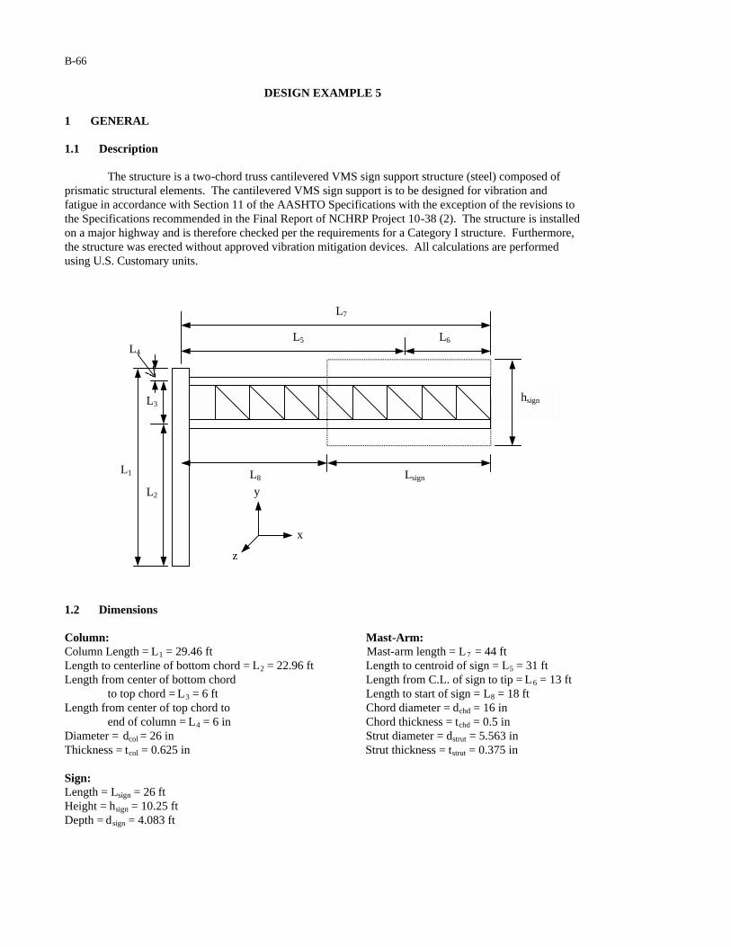
B-66
DESIGN EXAMPLE 5 1 GENERAL 1.1 Description
The structure is a two-chord truss cantilevered VMS sign support structure (steel) composed of prismatic structural elements. The cantilevered VMS sign support is to be designed for vibration and fatigue in accordance with Section 11 of the AASHTO Specifications with the exception of the revisions to the Specifications recommended in the Final Report of NCHRP Project 10-38 (2). The structure is installed on a major highway and is therefore checked per the requirements for a Category I structure. Furthermore, the structure was erected without approved vibration mitigation devices. All calculations are performed using U.S. Customary units.
1.2 Dimensions Column: Mast-Arm: Column Length = L1 = 29.46 ft Mast-arm length = L = 44 ft 7
Length to centerline of bottom chord = L2 = 22.96 ft Length to centroid of sign = L5 = 31 ft Length from center of bottom chord Length from C.L. of sign to tip = L6 = 13 ft
to top chord = L3 = 6 ft Length to start of sign = L8 = 18 ft Length from center of top chord to Chord diameter = dchd = 16 in
end of column = L4 = 6 in Chord thickness = tchd = 0.5 in Diameter = dcol = 26 in Strut diameter = dstrut = 5.563 in Thickness = tcol = 0.625 in Strut thickness = tstrut = 0.375 in Sign: Length = Lsign = 26 ft Height = hsign = 10.25 ft Depth = dsign = 4.083 ft
L1
L2
L3
L5 L6
hsign
L8 Lsign
L7
L4
x
z
y

B-67
1.3 Critical Fatigue Details 1. Anchor rods (Detail 5 in Table 11-2) 2. Column-to-baseplate fillet-welded socket connection (Detail 16 in Table 11-2) 3. Fillet-welded stiffener at column base (Details 22 and 23 in Table 11-2) 4. Column-to-stub pass-through connection (Detail 18 in Table 11-2) 5. Fillet-welded stiffener at flange plate (Detail 20 in Table 11-2) 6. Splice bolts (Detail 5 in Table 11-2) 7. Fillet-welded tube-to-tube connections within the truss (Detail 19 in Table 11-2) 2 CALCULATION OF LIMIT STATE FATIGUE LOADS 2.1 Galloping The equivalent static shear range to be applied to the sign attachment is calculated in accordance with Equation 11-1:
( )( ) psfIP FG 210.12121 ===
where IF = 1.0 (Table 11-1) is the importance factor used in the design of a Category I sign support structure for galloping. The area of the sign projected on a vertical plane is calculated by:
( ) ( )( ) 25.26625.1026 ftftfthLA signsignvsign ===
where Lsign = 26 ft. is the length of the sign and h sign = 10.25 ft. is the height of the sign. The equivalent static shear load range to be applied to the sign attachment is calculated by:
( ) ( )( ) kipsftAPFvsignGG 60.55.26621 2 ===
where (Asign)v = 266.5 ft2 is the area of the sign projected on a vertical plane. 2.2 Vortex Shedding As per the requirements of Section 11.7.2, vortex shedding need not be considered in the design of cantilevered sign support structures for vibration and fatigue. 2.3 Natural Wind Gusts It is assumed that the support structure will be erected at a location where the annual mean wind velocity is 5 m/s. The equivalent static pressure range to be applied to the tubular members is calculated in accordance with Equation 11-5:
( )( ) psfICP FdNW 72.511.12.52.5 ===

B-68
where IF = 1 (Table 11-1) is the importance factor used in the design of a Category I support structure for natural wind, and Cd = 1.1 is a conservative estimate of the drag coefficient for a circular cylinder (Table 3-5). The equivalent static load range to be applied to the column is calculated by:
( ) ( ) ( ) ( ) ( )( )( )[ ] lbinftinftpsfdLPAPF colNWvcolNWcolNW 36512/12646.2972.51 ====
where (Acol)v is the area of the column projected on the vertical plane, L = 29.46 ft. is the length of the 1
column, dcol = 26 in. is the diameter of the column. The equivalent static load range applied to each of the chords is calculated by:
( ) ( ) ( ) ( ) ( )( )( )[ ] lbinftinftpsfdLPAPF chdNWvchdNWchdNW 13712/1161872.58 ====
where (Achd)v is the area of the chord projected on a vertical plane, L8 = 18 ft. is the length of the chord exposed to the wind, and dchd = 16 in. is the diameter of the chord. Note: The area of the chord behind the sign is excluded from the calculation of the equivalent load range. The equivalent static load range acting on each of the brace members in the truss is neglected in this design example. The equivalent static load range to be applied to the sign attachment is calculated by:
( ) ( ) ( )( )[ ]( ) kipsftpsfAPFvsignNWsignNW 36.25.2667.12.5 2 ===
where (Asign)v = 266.5 ft2 is the area of the sign projected on a vertical plane and Cd =1.7 is the drag coefficient for a VMS sign (Table 3-5). 2.4 Truck Gusts It is assumed that the support structure will be erected at a location where the posted limit is not significantly less than 65 mph. The maximum equivalent static pressure range to be applied to a structure is calculated in accordance with the modified version of Equation 11-6 recommended in this report:
psfCICP dFdTG 8.188.18 ==
where IF = 1.0 (Table 11-1) is the importance factor used in the design of a Category I sign support structure for truck gusts. As per the recommended revisions to Section 11.7.4, truck gust pressures decrease linearly between elevations of 19.7 and 32.8 ft. For this example, it is assumed that the base of the column is at the same elevation as the roadway surface. Therefore, the elevation of the bottom of the VMS is:
ftftft
fthL
Ly signsign 84.20
2
25.10
2
696.22
223
2 =−+=−+=

B-69
Similarly, the elevation of the bottom of the bottom chord is:
( )ft
inftinft
dLy chd
chd 29.222
12/11696.22
22 =−=−=
Therefore, the modified truck gust pressures are:
psfCpsfftft
ftftCP ddsignTG 2.17
7.198.32
7.1984.2018.18, =
−−−=
psfCpsfftft
ftftCP ddchdTG 1.15
7.198.32
7.1929.2218.18, =
−−−=
As per the recommended revisions to Section 11.7.4, the equivalent static pressure is to be applied along the outermost 12 ft. of the cantilever. The equivalent static load range to be applied to the sign attachment is calculated by:
( ) ( ) ( ) ( )( )[ ] ( )( )[ ] kipsftftdLPAPF signsignsignTGhsignsignTGsignTG 43.1083.4127.12.17,, ====
where (Asign)h is the area of the sign (exposed to the truck gust) projected on a horizontal plane, Lsign = 12 ft. is the length of the sign (exposed to the truck gust), dsign = 4.083 ft. is the depth of the sign in the direction of traffic, and Cd =1.7 is the drag coefficient used for a VMS sign (Table 3-5). The equivalent static load range to be applied to the bottom chord is calculated by:
( ) ( ) ( ) ( )( )[ ] ( )( )( )[ ] kipsinftinftdLPAPF chdsignchdTGhchdchdTGchdTG 27.012/116121.11.15,, ====
where (Asign)h is the area of the bottom chord (exposed to the truck gust) projected on a horizontal plane, Lsign = 12 ft. is the length of the sign (exposed to the truck gust), dchd = 16 in. is the diameter of the chord, and Cd = 1.1 is a conservative estimate of the drag coefficient for a circular cylinder (Table 3-5). 3 CALCULATION OF BENDING MOMENTS 3.1 Moment Due to Galloping The bending moment at the centerline of the column (about the z-axis) is calculated by:
( ) ( )( ) ftkftkipsLFM GGz −=== 1743160.55
3.2 Moment Due to Natural Wind Gusts The bending moment at the base of the column (about the x-axis) is calculated by:
( ) ( ) ( ) ( ) ( ) ( ) ( )
+++++
=
223
23221 L
LFLLFLFL
FM signNWchdNWchdNWcolNWNWx
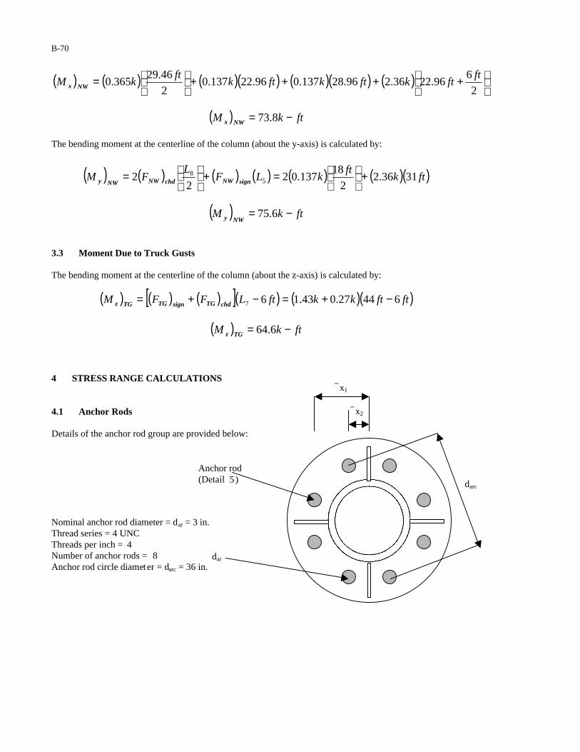
B-70
( ) ( ) ( )( ) ( )( ) ( )
++++
=
2
696.2236.296.28137.096.22137.0
2
46.29365.0
ftftkftkftk
ftkM NWx
( ) ftkM NWx −= 8.73
The bending moment at the centerline of the column (about the y-axis) is calculated by:
( ) ( ) ( ) ( ) ( ) ( )( )ftkft
kLFL
FM signNWchdNWNWy 3136.22
18137.02
22 5
8 +
=+
=
( ) ftkMNWy −= 6.75
3.3 Moment Due to Truck Gusts The bending moment at the centerline of the column (about the z-axis) is calculated by:
( ) ( ) ( )[ ]( ) ( )( )ftftkkftLFFM chdTGsignTGTGz 64427.043.167 −+=−+=
( ) ftkM TGz −= 6.64
4 STRESS RANGE CALCULATIONS 4.1 Anchor Rods Details of the anchor rod group are provided below:
Nominal anchor rod diameter = dar = 3 in. Thread series = 4 UNC Threads per inch = 4 Number of anchor rods = 8 Anchor rod circle diameter = darc = 36 in.
dar
x1
Anchor rod (Detail 5 ) darc
x2
B-71
4.1.1 Moment of Inertia of the Anchor Rod Group The centroidal distance to each of the anchor rods is calculated by:
( ) ( )
( ) ( ) inind
x
inind
x
arc
arc
89.63827.02
365.67cos
2
63.169239.02
365.22cos
2
2
1
=
=°
=
=
=°
=
where x is the centroidal distance to each of the anchor rods and darc = 36 in. is the diameter of the anchor rod circle. The tensile stress area of each of the anchor rods is calculated by:
222
97.54
9743.03
4
9743.0
4inin
ndA arT =
−=
−= ππ
where AT is the tensile stress area of each anchor rod (Equation 5-23), d ar = 3 in. is the nominal anchor rod diameter, and n = 4 is the number of threads per inch. The moment of inertia of the anchor rod group is calculated by:
( ) ( ) ( )[ ] 42222 773863.1689.697.54 ininininxAI Tar =+=Σ=
where AT = 5.97 in2 is the tensile stress area of each anchor rod and x is the centroidal distance to each of the anchor rods. 4.1.2 Anchor Rod Stress Range Based upon the calculations of Section 3, galloping controls the design of the anchor rod group for fatigue. Therefore, the axial stress range in each of the anchor rods is calculated by:
( ) ( ) ( )( )( )ksi
in
inftinftk
I
cMS
ar
GzarR 86.4
7738
18/121744
=−==
Anchor rods are classified as Category D fatigue details (Detail 5 in Table 11-2). The constant amplitude fatigue limit corresponding to Category D is 7 ksi (Table 11-3). Since the calculated stress range (4.86 ksi) is less than the constant amplitude fatigue limit (7ksi), the anchor rod group is adequately designed for fatigue.
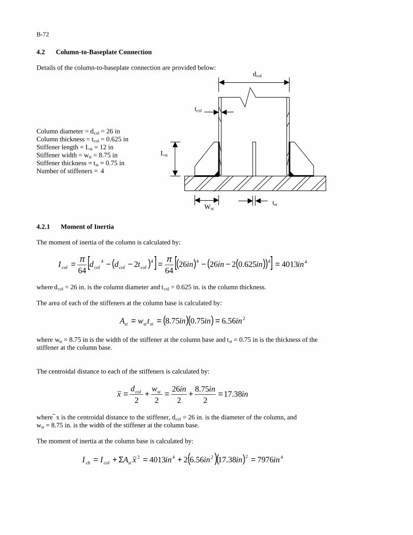
B-72
4.2 Column-to-Baseplate Connection Details of the column-to-baseplate connection are provided below:
Column diameter = dcol = 26 in Column thickness = tcol = 0.625 in Stiffener length = Lst = 12 in Stiffener width = wst = 8.75 in Stiffener thickness = tst = 0.75 in Number of stiffeners = 4
4.2.1 Moment of Inertia The moment of inertia of the column is calculated by:
( )[ ] ( ) ( )( )[ ] 44444 4013625.02262664
264
inininintddI colcolcolcol =−−=−−= ππ
where dcol = 26 in. is the column diameter and tcol = 0.625 in. is the column thickness. The area of each of the stiffeners at the column base is calculated by:
( )( ) 256.675.075.8 ininintwA ststst ===
where wst = 8.75 in is the width of the stiffener at the column base and tst = 0.75 in is the thickness of the stiffener at the column base. The centroidal distance to each of the stiffeners is calculated by:
inininwd
x stcol 38.172
75.8
2
26
22=+=+=
where x is the centroidal distance to the stiffener, dcol = 26 in. is the diameter of the column, and wst = 8.75 in. is the width of the stiffener at the column base. The moment of inertia at the column base is calculated by:
( )( ) 42242 797638.1756.624013 ininininxAII stcolcb =+=Σ+=
dcol
tcol
Lst
Wst tst

B-73
Note that the individual moments of inertia of each of the stiffeners are neglected in the calculation of the moment of inertia of the column base. 4.2.2 Stress Range at the Column-to-Baseplate Connection Based upon the calculations of Section 3, truck-induced gusts control the design of the fillet-welded column-to-baseplate connection for fatigue. Therefore, the stress range at the column-to-baseplate connection is calculated by:
( ) ( ) ( )( )( )ksi
in
inftinftk
I
cMS
cb
GzcolR 40.3
7976
13/121744
=−==
The fillet-welded column-to-baseplate connection is classified as a Category E’ fatigue detail (Detail 16 in Table 11-2). The constant amplitude fatigue limit corresponding to Category E’ is 2.6 ksi (Table 11-3). Since the calculated stress range (3.40 ksi) is greater than the constant amplitude fatigue limit (2.6 ksi), the column-to-baseplate connection is inadequately designed for fatigue. Potential Redesigns: 1. Assuming: (1) the fatigue resistance of the connection is not improved (i.e. a Category E’ socket connection (Detail 16 in Table 11-2) is used), and (2) the diameter and thickness of the column are not increased (i.e. dcol = 26 in. and tcol = 0.625 in.), the connection will be adequately designed for fatigue if four additional stiffeners are added at 45o angles to the original stiffeners. 2. Assuming: (1) the diameter and thickness of the column are not increased (i.e. dcol = 26 in. and tcol = 0.625 in.) and (2) the width and thickness of the stiffeners are not increased (i.e. wst = 8.75 in. and tst = 0.75 in.), the connection will be adequately designed for fatigue if the fatigue resistance of the column-to-baseplate connection is improved to Category E by utilizing a groove-welded connection in which the backing ring is attached with either a full-penetration groove weld or a continuous fillet weld (Detail 11 in Table 11-2 as modified in this report). 4.2.3 Stress Range at Stiffener-to-Baseplate Connection Based upon the calculations of Section 3, galloping controls the design of the stiffener-to-baseplate connection for fatigue. Therefore, the stress range at the stiffener-to-baseplate connection is calculated by:
( ) ( ) ( )( )( )ksi
in
ininftinftk
I
cMS
cb
GZbpstR 69.5
7976
75.813/121744
=+−==−
The stiffener-to-baseplate connection is a transverse load-bearing fillet-welded attachment with a thickness greater than 0.5 inches (Detail 23 in Table 11-2). Therefore, the constant amplitude fatigue limit of this detail must be reduced in accordance with the following relationship:
( )ksi
in
in
in
ksit
t
H
FF
st
stCnn 35.4
75.0
75.0
375.072.055.0
10
072.055.0
6
1
6
1=
+
=
+
∆=∆
B-74
where H = 0.375 inches is the effective throat of the stiffener-to-baseplate fillet weld, tst = 0.75 inches is the thickness of the stiffener plate, ∆Fn is the modified fatigue strength, and ∆Fn
C = 10 ksi is the CAFL for a Category C detail. Since the calculated stress range (5.69 ksi) is greater than the constant amplitude fatigue limit (4.35 ksi), the stiffener-to-baseplate connection is inadequately designed for fatigue. Potential Redesigns: 1. Assuming: (1) the diameter and thickness of the column are not increased (i.e. dcol = 26 in. and tcol = 0.625 in.) and (2) the width and thickness of the stiffeners are not increased (i.e. wst = 8.75 in. and tst = 0.75 in.), the connection will be adequately designed for fatigue if four additional stiffeners are added at 45o angles to the original stiffeners. 2. Assuming: (1) the diameter and thickness of the column are not increased (i.e. dcol = 26 in. and tcol = 0.625 in.) and (2) the width and thickness of the stiffeners are not increased (i.e. wst = 8.75 in. and tst = 0.75 in.), the connection will be adequately designed for fatigue if the effective weld throat is increased to 0.5 in. 4.2.4 Stress Range at Termination of Stiffener Based upon the calculations of Section 3, galloping controls the design of the stiffener-to-column connection. Therefore, the stress range at the termination of the stiffener is calculated by:
( ) ( ) ( )( )( )ksi
in
inftinftk
I
cMS
col
GZcolstR 76.6
4013
13/121744
=−==−
The weld termination at the end of the stiffener is classified as a Category E fatigue detail (Detail 20 in Table 11-2). The constant amplitude fatigue limit corresponding to Category E is 4.5 ksi (Table 11-3). Since the calculated stress range (6.76 ksi) is greater than the constant amplitude fatigue limit (4.5 ksi), the weld termination at the end of the stiffener is inadequately designed for fatigue. Potential Redesign: 1. Assuming: the column diameter and thickness remain unchanged (i.e. dcol = 26 in. and tcol = 0.625 in.), the weld termination at the end of the stiffener will be adequately designed for fatigue if the fatigue resistance of the weld termination is improved to Category D by ensuring that the stiffeners intersect the column at a radius greater than 2 inches or at an angle less than 60o (i.e. Detail 22 in Table 11-2). 4.3 Column-to-Stub Connection The details of the column-to-stub connection are given below. Because both of the members in the connection are subjected to loads, the detail must be checked with respect to the stress in each member. Note: Both the pass-through column-to-stub connection and the fillet-welded socket stub-to-flange plate connection are Category E’ details. Because the stress in the stub is greatest at the column face, the stress range at the column face (and not at the flange plate) will always control the design of the stub. Thus, the adequacy of the stub-to-flange plate connection does not need to be checked.
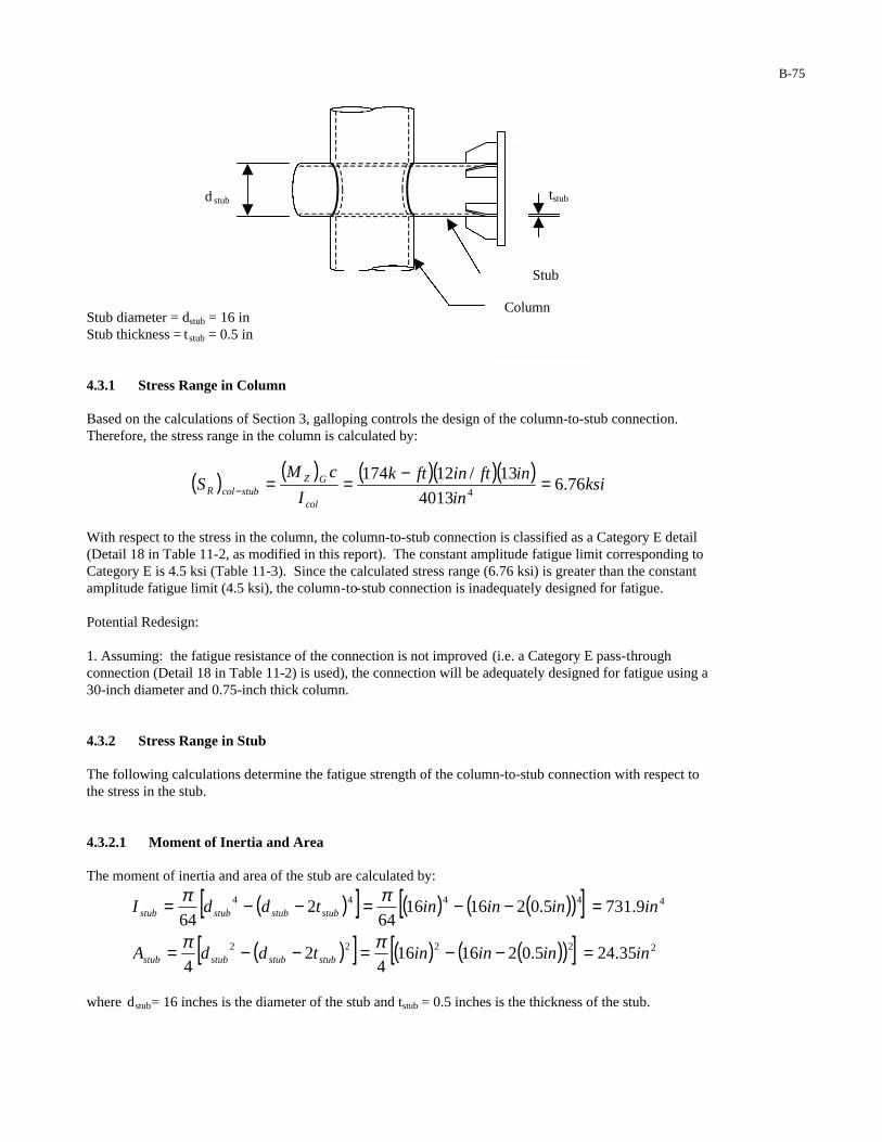
B-75
Stub diameter = dstub = 16 in Stub thickness = t stub = 0.5 in 4.3.1 Stress Range in Column Based on the calculations of Section 3, galloping controls the design of the column-to-stub connection. Therefore, the stress range in the column is calculated by:
( ) ( ) ( )( )( )ksi
in
inftinftk
I
cMS
col
GZstubcolR 76.6
4013
13/121744
=−==−
With respect to the stress in the column, the column-to-stub connection is classified as a Category E detail (Detail 18 in Table 11-2, as modified in this report). The constant amplitude fatigue limit corresponding to Category E is 4.5 ksi (Table 11-3). Since the calculated stress range (6.76 ksi) is greater than the constant amplitude fatigue limit (4.5 ksi), the column-to-stub connection is inadequately designed for fatigue. Potential Redesign: 1. Assuming: the fatigue resistance of the connection is not improved (i.e. a Category E pass-through connection (Detail 18 in Table 11-2) is used), the connection will be adequately designed for fatigue using a 30-inch diameter and 0.75-inch thick column. 4.3.2 Stress Range in Stub The following calculations determine the fatigue strength of the column-to-stub connection with respect to the stress in the stub. 4.3.2.1 Moment of Inertia and Area The moment of inertia and area of the stub are calculated by:
( )[ ] ( ) ( )( )[( )[ ] ( ) ( )( )[
]] 22222
44444
35.245.0216164
24
9.7315.02161664
264
inininintddA
inininintddI
stubstubstubstub
stubstubstubstub
=−−=−−=
=−−=−−=
ππ
ππ
where dstub = 16 inches is the diameter of the stub and t stub = 0.5 inches is the thickness of the stub.
d stub
tstub
Column
Stub
B-76
4.3.2.2 Stress Range in Stub at Column Face Based upon the calculations of Section 3, galloping controls the design of the column-to-stub connection. The maximum axial force and moment in the stub were found using Visual Analysis software. Therefore, the stress range in the stub is calculated by:
( ) ( ) ( )( )( )ksi
in
inftinftk
in
k
I
cM
A
AxialS
stub
GZ
stub
GcolstubR 89.5
9.731
8/1223.37
35.24
40.2442
=−+=+=−
where AxialG = 24.40 kips and (MZ)G = 37.23 k-ft are the axial force and internal bending moment, respectively, in the stub at the column face. With respect to the stress in the stub, the column-to-stub connection is classified as a Category E’ detail (Detail 18 in Table 11-2). The constant amplitude fatigue limit corresponding to Category E’ is 2.6 ksi (Table 11-3). Since the calculated stress range (5.89 ksi) is greater than the constant amplitude fatigue limit (2.6 ksi), the column-to-stub connection is inadequately designed for fatigue. Potential Redesigns: 1. Assuming: the fatigue resistance of the connection is not improved (i.e. a Category E’ pass-through connection (Detail 18 in Table 11-2) is used), the connection will be adequately designed for fatigue using a 21-inch diameter and 0.75-inch thick stub. 2. Assuming: (1) the fatigue resistance of the connection is not improved (i.e. a Category E’ pass-through connection (Detail 18 in Table 11-2) is used), (2) the thickness of the stub is not increased (i.e. tstub = 0.5 inches), and (3) the diameter of the stub is not increased (i.e. dstub = 16 inches), the connection will be adequately designed for fatigue if the stiffeners at the stub-to-flange plate connection are extended the length of the stub so that they also intersect the column (wst = 6.5 inches and tst = 0.5 inches). 4.4 Stress Range at Termination of Stiffener on Stub If the stub-to-flange plate stiffeners are not extended back to the column as is recommended in the second redesign above, the stress at the stiffener termination must be checked for fatigue. Based upon the calculations of Section 3, galloping controls the design of the end of the stiffener-to-stub connection. Therefore, the stress range at the termination of the stiffener on the stub is calculated by:
( ) ( ) ( )( )( )ksi
in
inftinftk
in
k
I
cM
A
AxialS
stub
Gz
stub
GststubR 72.3
9.731
8/1273.20
35.24
40.2442
=−+=+=−
where AxialG = 24.40 kips and (Mz)G = 20.73 k-ft are the axial force and internal bending moment, respectively, in the stub at the stiffener termination. Since the stiffener is greater than four inches long, the connection is classified as a Category E detail (Detail 20 in Table 11-2). The corresponding constant amplitude fatigue limit for Category E is 4.5 ksi (Table 11-3). Since the calculated stress range (3.72 ksi) is less than the constant amplitude fatigue limit (4.5 ksi), the stiffener-to-stub connection is adequately designed for fatigue.
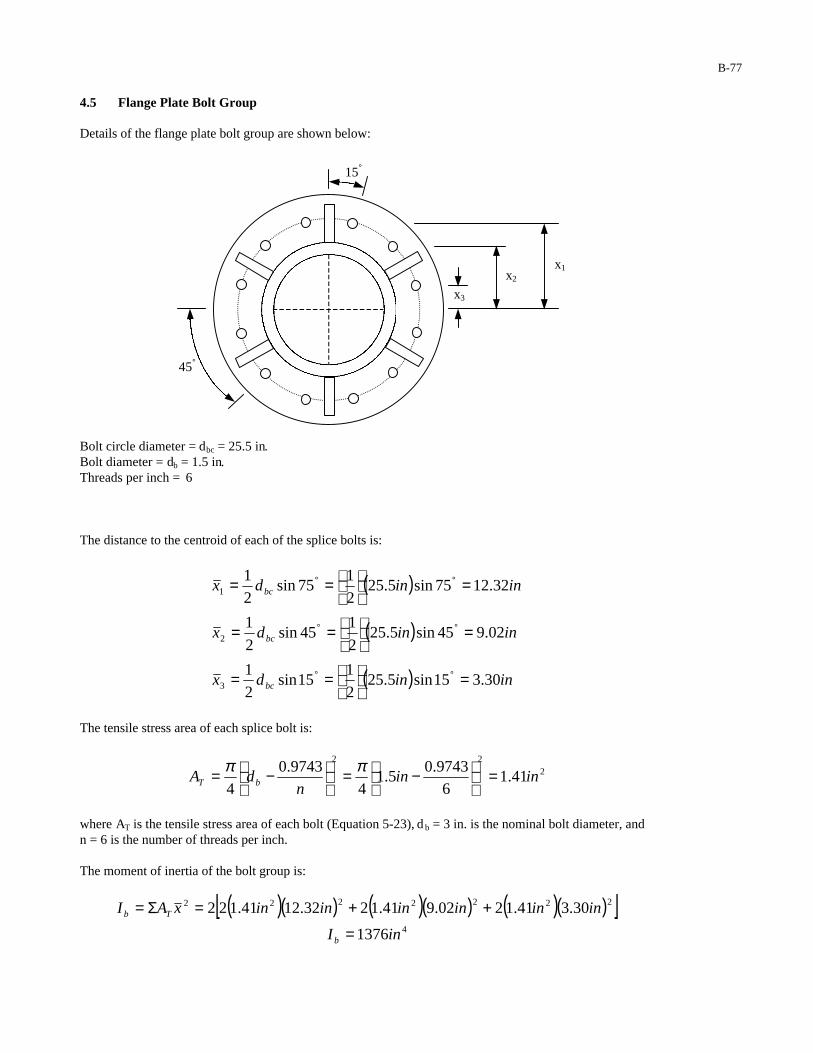
B-77
4.5 Flange Plate Bolt Group Details of the flange plate bolt group are shown below:
Bolt circle diameter = dbc = 25.5 in. Bolt diameter = db = 1.5 in. Threads per inch = 6 The distance to the centroid of each of the splice bolts is:
( )
( )
( ) inindx
inindx
inindx
bc
bc
bc
30.315sin5.252
115sin
2
1
02.945sin5.252
145sin
2
1
32.1275sin5.252
175sin
2
1
3
2
1
=
==
=
==
=
==
°°
°°
°°
The tensile stress area of each splice bolt is:
222
41.16
9743.05.1
4
9743.0
4inin
ndA bT =
−=
−= ππ
where AT is the tensile stress area of each bolt (Equation 5-23), d b = 3 in. is the nominal bolt diameter, and n = 6 is the number of threads per inch.
The moment of inertia of the bolt group is:
( )( ) ( )( ) ( )( )[ ]4
2222222
1376
30.341.1202.941.1232.1241.122
inI
ininininininxAI
b
Tb
=
++=Σ=
15°
45°
x2
x1
x3
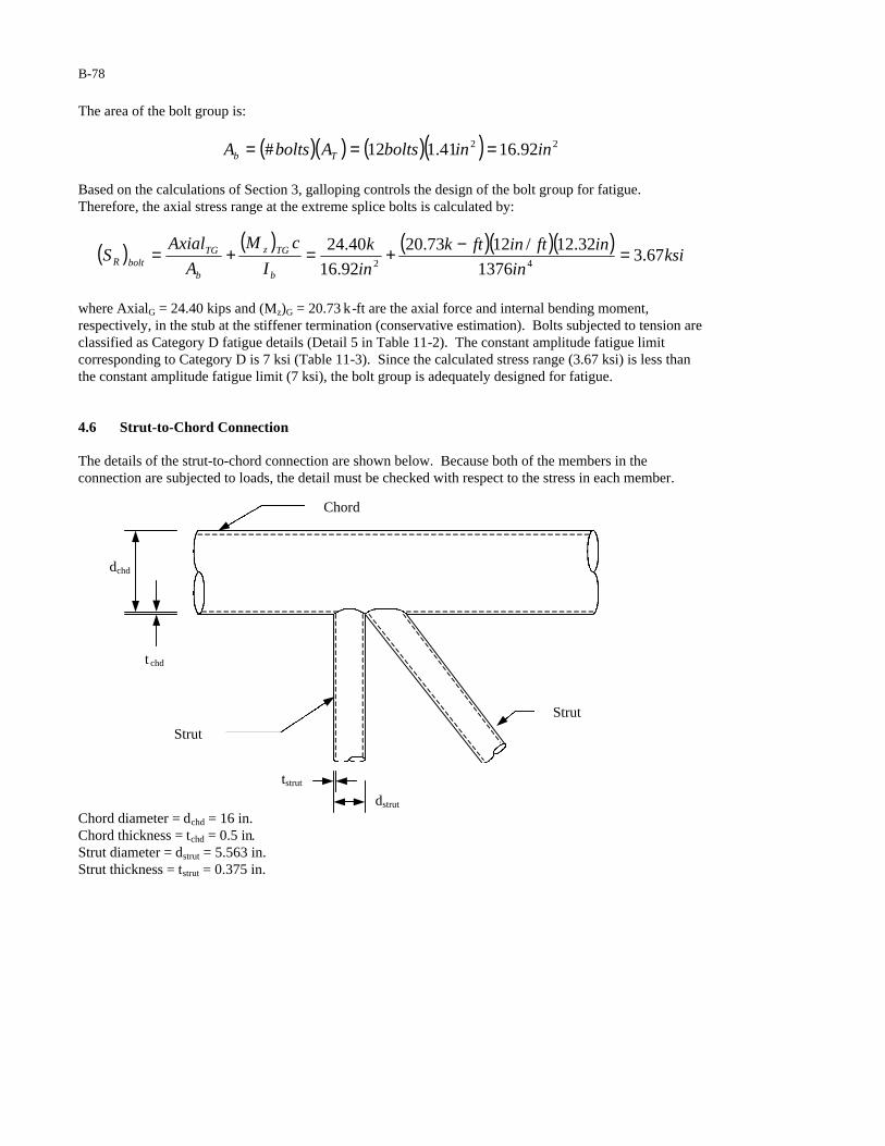
B-78
The area of the bolt group is:
( )( ) ( )( ) 22 92.1641.112# ininboltsAboltsA Tb ===
Based on the calculations of Section 3, galloping controls the design of the bolt group for fatigue. Therefore, the axial stress range at the extreme splice bolts is calculated by:
( ) ( ) ( )( )( )ksi
in
inftinftk
in
k
I
cM
A
AxialS
b
TGz
b
TGboltR 67.3
1376
32.12/1273.20
92.16
40.2442
=−+=+=
where AxialG = 24.40 kips and (Mz)G = 20.73 k-ft are the axial force and internal bending moment, respectively, in the stub at the stiffener termination (conservative estimation). Bolts subjected to tension are classified as Category D fatigue details (Detail 5 in Table 11-2). The constant amplitude fatigue limit corresponding to Category D is 7 ksi (Table 11-3). Since the calculated stress range (3.67 ksi) is less than the constant amplitude fatigue limit (7 ksi), the bolt group is adequately designed for fatigue. 4.6 Strut-to-Chord Connection The details of the strut-to-chord connection are shown below. Because both of the members in the connection are subjected to loads, the detail must be checked with respect to the stress in each member.
Chord diameter = dchd = 16 in. Chord thickness = tchd = 0.5 in. Strut diameter = dstrut = 5.563 in. Strut thickness = tstrut = 0.375 in.
tstrut
dchd
Chord
Strut Strut
t chd
dstrut

B-79
4.6.1 Moment of Inertia and Area of Chord The moment of inertia and area of the chord are calculated by:
( )[ ] ( ) ( )( )[( )[ ] ( ) ( )( )[
]] 22222
44444
35.245.0216164
24
9.7315.02161664
264
inininintddA
inininintddI
chdchdchdchd
chdchdchdchd
=−−=−−=
=−−=−−=
ππ
ππ
4.6.2 Stress Range in Chord Based upon the calculations of Section 3, galloping controls the design of the strut-to-chord connection. Therefore, the stress range in the chord is calculated by:
( ) ( ) ( )( )( )ksi
in
inftinftk
in
k
I
cM
A
AxialS
chd
TGz
chd
TGstrutchdR 18.3
9.731
8/1260.16
35.24
40.2442
=−+=+=−
where AxialG = 24.40 kips and (Mz)G = 16.60 k-ft are the axial force and internal bending moment, respectively, in the chord at the strut connection. With respect to the stress in the chord, the strut-to-chord connection is classified as a Category E detail (Detail 19 in Table 11-2). The corresponding constant amplitude fatigue limit for Category E is 4.5 ksi (Table 11-3). Since the calculated stress range (3.18 ksi) is less than the constant amplitude fatigue limit (4.5 ksi), the strut-to-chord connection is adequately designed for fatigue. 4.6.3 Moment of Inertia and Area of Strut The moment of inertia and area of the strut are calculated by:
( )[ ] ( ) ( )( )[( )[ ] ( ) ( )( )[
]] 22222
44444
11.6375.02563.5563.54
24
67.20375.02563.5563.564
264
inininintddA
inininintddI
strutstrutstrutstrut
strutstrutstrutstrut
=−−=−−=
=−−=−−=
ππ
ππ
4.6.4 Stress Range in Strut at Chord Face Based upon the calculations of Section 3, galloping controls the design of the strut-to-chord connection. Therefore, the stress range in the strut is calculated by:
( ) ( ) ( )( )( )ksi
in
inftinftk
in
k
I
cM
A
AxialS
strut
Gz
strut
GchdstrutR 25.2
67.20
2/563.5/1249.0
11.6
91.842
=−+=+=−
where AxialG = 8.91 kips and (MZ)G = 0.49 k-ft are the axial force and internal bending moment, respectively, in the strut at the chord connection. With respect to the strut, the strut-to-chord connection is classified as a Category ET detail (Detail 19 in Table 11-2). The corresponding constant amplitude fatigue limit for Category ET is 1.2 ksi (Table 11-3). Since the calculated stress range (2.25 ksi) is greater than the constant amplitude fatigue limit (1.2 ksi), the strut-to-chord connection is inadequately designed for fatigue.

B-80
Potential Redesign: 1. Assuming: (1) the diameter and thickness of the strut are not increased (i.e. dstrut = 5.563 in. and tstrut = 0.375 in.), the connection will be adequately designed for fatigue if the fatigue resistance of the connection is improved to Category E’ (i.e. a slotted tube-to-gusset connection without a coped hole (Detail 15 in Table 11-2) is used). 5 DEFLECTION As per the requirements of Section 11.8, cantilevered sign support structures with trussed mast-arms need not be designed to satisfy the deflection limit state.
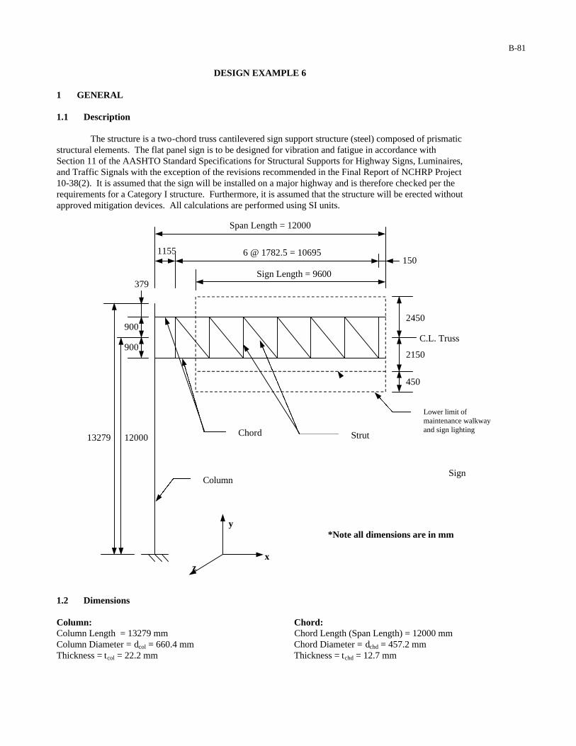
B-81
DESIGN EXAMPLE 6 1 GENERAL 1.1 Description The structure is a two-chord truss cantilevered sign support structure (steel) composed of prismatic structural elements. The flat panel sign is to be designed for vibration and fatigue in accordance with Section 11 of the AASHTO Standard Specifications for Structural Supports for Highway Signs, Luminaires, and Traffic Signals with the exception of the revisions recommended in the Final Report of NCHRP Project 10-38(2). It is assumed that the sign will be installed on a major highway and is therefore checked per the requirements for a Category I structure. Furthermore, it is assumed that the structure will be erected without approved mitigation devices. All calculations are performed using SI units.
y *Note all dimensions are in mm
x
z
1.2 Dimensions Column: Chord: Column Length = 13279 mm Chord Length (Span Length) = 12000 mm Column Diameter = dcol = 660.4 mm Chord Diameter = dchd = 457.2 mm Thickness = tcol = 22.2 mm Thickness = tchd = 12.7 mm
900
Column
Chord Strut
Sign
Lower limit of maintenance walkway and sign lighting
1155
Span Length = 12000
6 @ 1782.5 = 10695 150
2450
2150
450
C.L. Truss
379
900
13279 12000
Sign Length = 9600
B-82
Strut: Sign: Strut Diameter = dstrut = 141.3 mm Sign Length = 9600 mm Thickness = tstrut = 9.5 mm Height = 4600 mm 1.3 Critical Fatigue Details The following details are to be checked for fatigue:
1. Anchor Rods (Detail 5 in Table 11-2) 2. Weld termination at stiffener-to-column connection (Detail 20 in Table 11-2) 3. Weld termination at stiffener-to-baseplate connection (Detail 23 in Table 11-2) 4. Column-to-baseplate socket connection (Detail 16 in Table 11-2) 5. Reinforced handhole (Detail 20 in Table 11-2) 6. Column-to-stub pass-through connection (Detail 18 in Table 11-2) 7. Weld termination at stiffener-to-chord connection near chord splice (Detail 20 in Table 11-2) 8. Weld termination at stiffener-to-splice plate connection (Detail 23 in Table 11-2) 9. Chord-to-splice plate socket connection (Detail 16 in Table 11-2) 10. Splice bolts (Detail 5 in Table 11-2) 11. Strut-to-chord connection (Detail 19 in Table 11-2)
2 CALCULATION OF LIMIT STATE FATIGUE LOADS 2.1 Galloping The equivalent static shear range to be applied to the sign is calculated in accordance with equation 11-1:
( )( ) PaPaIP FG 10000.110001000 ===
where IF = 1.0 is the importance factor used in the design of a Category I sign support structure for galloping. The area of the sign projected on a vertical plane is:
( ) ( )( ) ( )( ) 2710416.446009600 mmxmmmmhLA signsignvsign ===
The equivalent static shear load range to be applied to the sign is:
( ) ( )( ) Nmm
mmmxPaAPF
vsignGG 441601000
110416.41000
227 =
==
2.2 Vortex Shedding As per the requirements of Section 11.7.2, vortex shedding need not be considered in the design of cantilevered sign support structures for vibration and fatigue.
B-83
2.3 Natural Wind It is assumed that the structure will be erected at a location where the yearly mean wind velocity is 5.2 m/s. Therefore, Equation 11-5 cannot be applied without modification. The equivalent static pressure range to be applied to the structure is calculated in accordance with equation C 11-5:
( ) ( ) ( )PaC
smC
VICP dd
meanFdNW 4.270
25
/2.50.1250
25250
22
=
=
=
where IF = 1.0 is the importance factor used in the design of a Category I sign support structure for natural wind gusts (Table 11-1), Cd is the drag coefficient (Table 3-5) (to be applied individually to each of the structural components considered), and Vmean is the yearly mean wind velocity. The equivalent static load range to be applied to the column is:
( ) ( ) [ ]
( ) ( ) ( )( )
=
==2
1000
14.6601327910.14.270
mm
mmmmmF
dLPAPF
colNW
colcolNWcolNWcolNW v
( ) NF colNW 2608=
where (Acol)v is the area of the column projected on a vertical plane and Cd = 1.10 is a conservative estimate of the drag coefficient for a circular cylinder (Table 3-5). The equivalent static load range to be applied to each of the chords is:
( ) ( ) ( ) ( )[ ]( ) ( ) ( )( )
=
==2
exposed
1000
12.4578.206910.14.270
mm
mmmmmF
dLPAPF
chdNW
chdchdNWvchdNWchdNW
( ) NF chdNW 281=
where (Achd)v is the area of the chord projected on a vertical plane and Cd = 1.10 is a conservative estimate of the drag coefficient for a circular cylinder (Table 3-5). *Note that the area of the chord behind the sign is excluded from the calculation of the equivalent static load range. Therefore, the exposed length of the chord is taken as the distance from the column face to the beginning of the sign panel (see below):
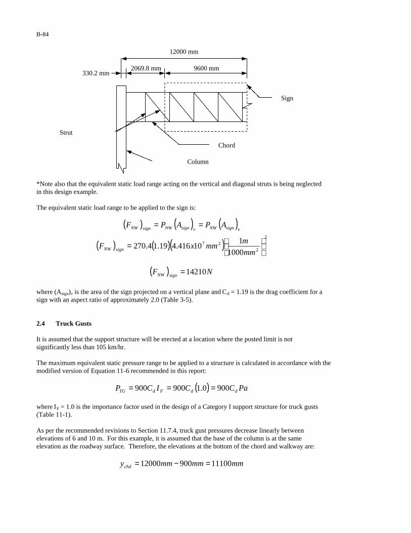
B-84
*Note also that the equivalent static load range acting on the vertical and diagonal struts is being neglected in this design example. The equivalent static load range to be applied to the sign is:
( ) ( ) ( )
( ) ( )( )2
227
1000
110416.419.14.270
=
==
mm
mmmxF
APAPF
signNW
vsignNWvsignNWsignNW
( ) NF signNW 14210=
where (Asign)v is the area of the sign projected on a vertical plane and Cd = 1.19 is the drag coefficient for a sign with an aspect ratio of approximately 2.0 (Table 3-5). 2.4 Truck Gusts It is assumed that the support structure will be erected at a location where the posted limit is not significantly less than 105 km/hr. The maximum equivalent static pressure range to be applied to a structure is calculated in accordance with the modified version of Equation 11-6 recommended in this report:
( ) PaCCICP ddFdTG 9000.1900900 ===
where IF = 1.0 is the importance factor used in the design of a Category I support structure for truck gusts (Table 11-1). As per the recommended revisions to Section 11.7.4, truck gust pressures decrease linearly between elevations of 6 and 10 m. For this example, it is assumed that the base of the column is at the same elevation as the roadway surface. Therefore, the elevations at the bottom of the chord and walkway are:
mmmmmmychd 1110090012000 =−=
Strut
Column
Chord
Sign
12000 mm
330.2 mm 2069.8 mm 9600 mm
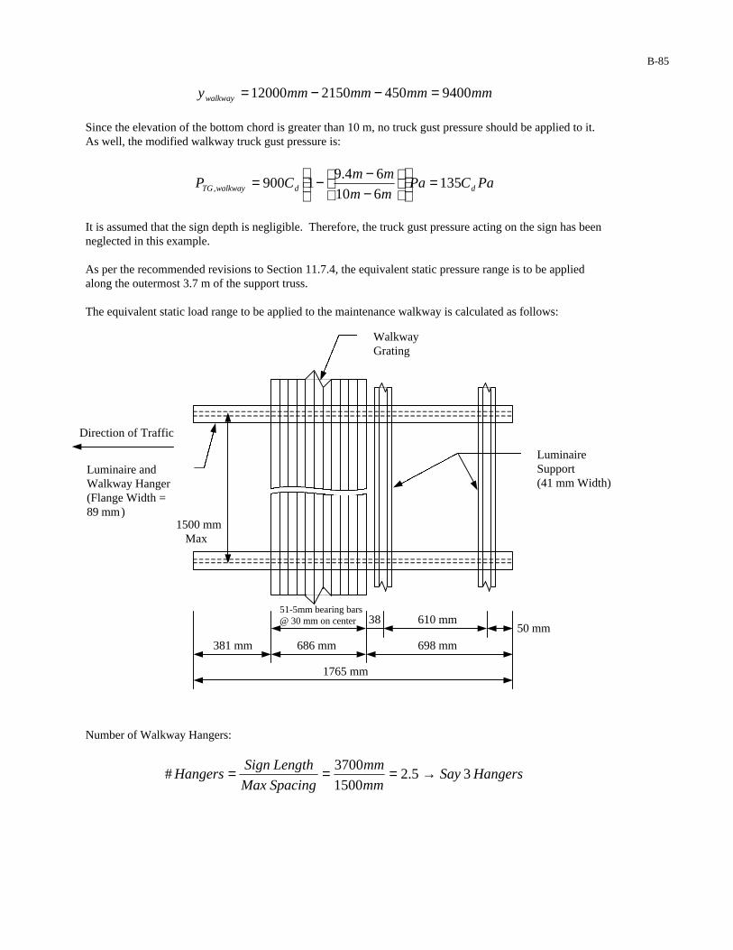
B-85
mmmmmmmmywalkway 9400450215012000 =−−=
Since the elevation of the bottom chord is greater than 10 m, no truck gust pressure should be applied to it. As well, the modified walkway truck gust pressure is:
PaCPamm
mmCP ddwalkwayTG 135
610
64.91900, =
−−−=
It is assumed that the sign depth is negligible. Therefore, the truck gust pressure acting on the sign has been neglected in this example.
As per the recommended revisions to Section 11.7.4, the equivalent static pressure range is to be applied along the outermost 3.7 m of the support truss. The equivalent static load range to be applied to the maintenance walkway is calculated as follows:
Number of Walkway Hangers:
HangersSaymm
mm
SpacingMax
LengthSignHangers 3 5.2
1500
3700
# →===
Luminaire Support (41 mm Width)
Luminaire and Walkway Hanger (Flange Width = 89 mm)
1500 mm Max
51-5mm bearing bars @ 30 mm on center
381 mm 686 mm
50 mm 610 mm 38
698 mm
1765 mm
Walkway Grating
Direction of Traffic

B-86
Number of Bearing Bars:
BarsSaymm
mm
Spacing
WidthWalkwayBars 23 9.22
30
686 # →===
The equivalent static load range to be applied to the walkway is:
( ) ( ) [ ]
( ) ( ) ( )( ) ( )
( ) NF
hangersmm
mmmmmF
wLPAPF
hangerTG
hangerTG
hangerhangerwalkwayTGhhangerwalkwayTGhangerTG
108
31000
18917657.1135
2
,,
=
=
==
where (Ahanger)h is the area of the hanger (exposed to the truck gust) projected on a horizontal plane and Cd = 1.7 is the drag coefficient for a sharp edged member (Table 3-5). The equivalent static load range to be applied to the walkway grating is:
( ) ( ) [ ]
( ) ( ) ( )( ) ( )Barsmm
mmmmmF
wLPAPF
gratingTG
gratingsignwalkwayTGhgratingwalkwayTGgratingTG
231000
1537007.1135
2
,,
=
==
( ) NF gratingTG 98=
where (Agrating)h is the area of the walkway grating (exposed to the truck gust) projected on a horizontal plane and Cd = 1.7 is the drag coefficient for a sharp-edged member (Table 3-5). *Note that only the area of the bearing bars has been included in the calculation of this force. Had the dimensions of the grating been known, the area of the grating would have also been included in the calculation. The equivalent static load range to be applied to the luminaire support is:
( ) ( ) [ ]
( ) ( ) ( )( ) ( )Supportsmm
mmmmmF
wLPAPF
lsTG
lssignwalkwayTGhlswalkwayTGlsTG
21000
14137007.1135
2
,,
=
==
( ) NF lsTG 70=
where (Als)h is the area of the luminaire support (exposed to the truck gust) projected on a horizontal plane and Cd = 1.7 is the drag coefficient for a sharp edged member (Table 3-5).
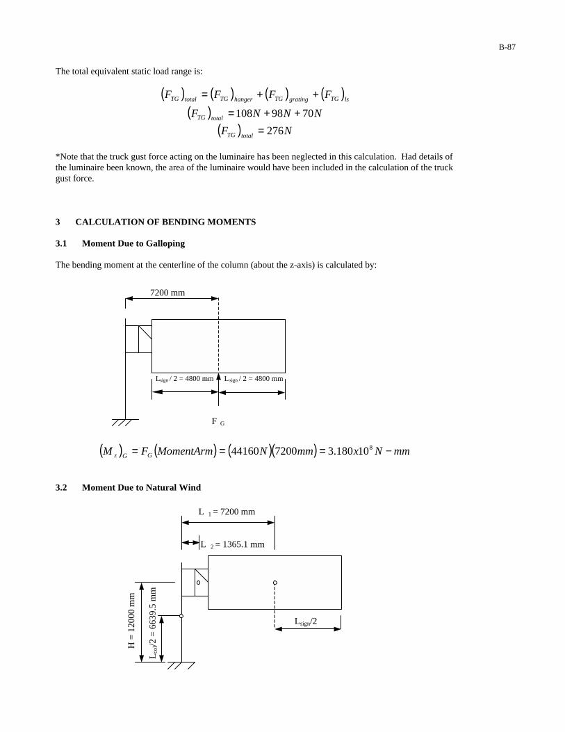
B-87
The total equivalent static load range is:
( ) ( ) ( ) ( )( )
( ) NF
NNNF
FFFF
totalTG
totalTG
lsTGgratingTGhangerTGtotalTG
276
7098108
=++=
++=
*Note that the truck gust force acting on the luminaire has been neglected in this calculation. Had details of the luminaire been known, the area of the luminaire would have been included in the calculation of the truck gust force. 3 CALCULATION OF BENDING MOMENTS 3.1 Moment Due to Galloping The bending moment at the centerline of the column (about the z-axis) is calculated by:
( ) ( ) ( )( ) mmNxmmNMomentArmFM GGz −=== 810180.3720044160
3.2 Moment Due to Natural Wind
H
= 1
2000
mm
Lco
l/2 =
663
9.5
mm
7200 mm
Lsign / 2 = 4800 mm Lsign / 2 = 4800 mm
F G
(FNW)chd (FNW)sign Lsign/2
L 1 = 7200 mm L 2 = 1365.1 mm
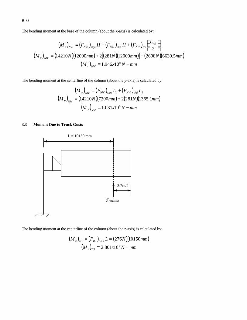
B-88
The bending moment at the base of the column (about the x-axis) is calculated by:
( ) ( ) ( ) ( )
( ) ( )( ) ( )( )[ ] ( )( )( ) mmNxM
mmNmmNmmNM
LFHFHFM
NWx
NWx
colcolNWchdNWsignNWNWx
−=
++=
++=
810946.1
5.663926081200028121200014210
2
The bending moment at the centerline of the column (about the y-axis) is calculated by:
( ) ( ) ( )( ) ( )( ) ( )( )
( ) mmNxM
mmNmmNM
LFLFM
NWy
NWy
chdNWsignNWNWy
−=
+=
+=
8
21
10031.1
1.13652812720014210
3.3 Moment Due to Truck Gusts
The bending moment at the centerline of the column (about the z-axis) is calculated by:
( ) ( ) ( )( )( ) mmNxM
mmNLFM
TGz
totalTGTGz
−=
==610801.2
10150276
3.7m/2 (FTG)total
L = 10150 mm
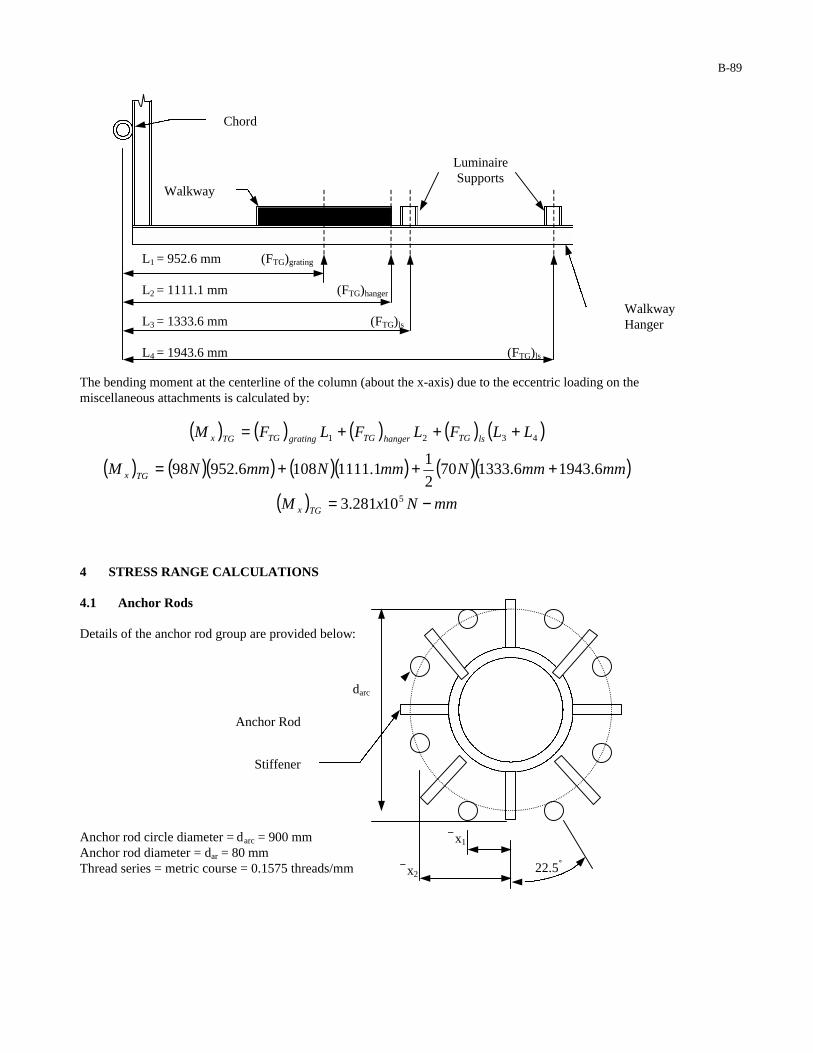
B-89
The bending moment at the centerline of the column (about the x-axis) due to the eccentric loading on the miscellaneous attachments is calculated by:
( ) ( ) ( ) ( ) ( )
( ) ( )( ) ( )( ) ( )( )
( ) mmNxM
mmmmNmmNmmNM
LLFLFLFM
TGx
TGx
lsTGhangerTGgratingTGTGx
−=
+++=
+++=
5
4321
10281.3
6.19436.1333702
11.11111086.95298
4 STRESS RANGE CALCULATIONS
4.1 Anchor Rods Details of the anchor rod group are provided below:
Anchor rod circle diameter = darc = 900 mm Anchor rod diameter = dar = 80 mm Thread series = metric course = 0.1575 threads/mm
L1 = 952.6 mm (FTG)grating
L2 = 1111.1 mm (FTG)hanger
L3 = 1333.6 mm (FTG)ls
L4 = 1943.6 mm (FTG)ls
Chord
Walkway
Walkway Hanger
Luminaire Supports
x1
x2
darc
Anchor Rod
Stiffener
22.5°
B-90
The distance to the centroid of each anchor rod is calculated by:
( )
( ) mmmmdx
mmmmdx
arc
arc
75.4155.67sin9002
15.67sin
2
1
21.1725.22sin9002
15.22sin
2
1
2
1
===
===
oo
oo
The tensile stress area of each anchor rod is calculated by
[ ]
( )[ ] 22
2
430635.6938.0804
/35.61
where938.04
mmA
threadmmesThreadSeri
PPdA
T
arT
=−=
==−=
π
π
The moment of inertia of the anchor rod group is:
( )( ) ( )( )[ ]49
22222
10488.3
21.1724306275.415430622
mmxI
mmmmmmmmxAI
ar
iTar
=
+=Σ=
4.1.1 Anchor Rod Stress Range Based upon the calculations of Section 3, galloping controls the design of the anchor rod group for fatigue. The axial stress range in each of the anchor rods is calculated by:
( ) ( ) ( )( )MPa
mmx
mmmmNx
I
cMS
b
GzarR 41
10488.3
4501018.349
8
=−==
Anchor rods are classified as Category D fatigue details (Detail 5 in Table 11-2). The constant amplitude fatigue limit corresponding to Category D is 45 MPa. Since the calculated stress range (41 MPa) is less than the constant amplitude fatigue limit (45 MPa), the anchor rod group is adequately designed for fatigue.
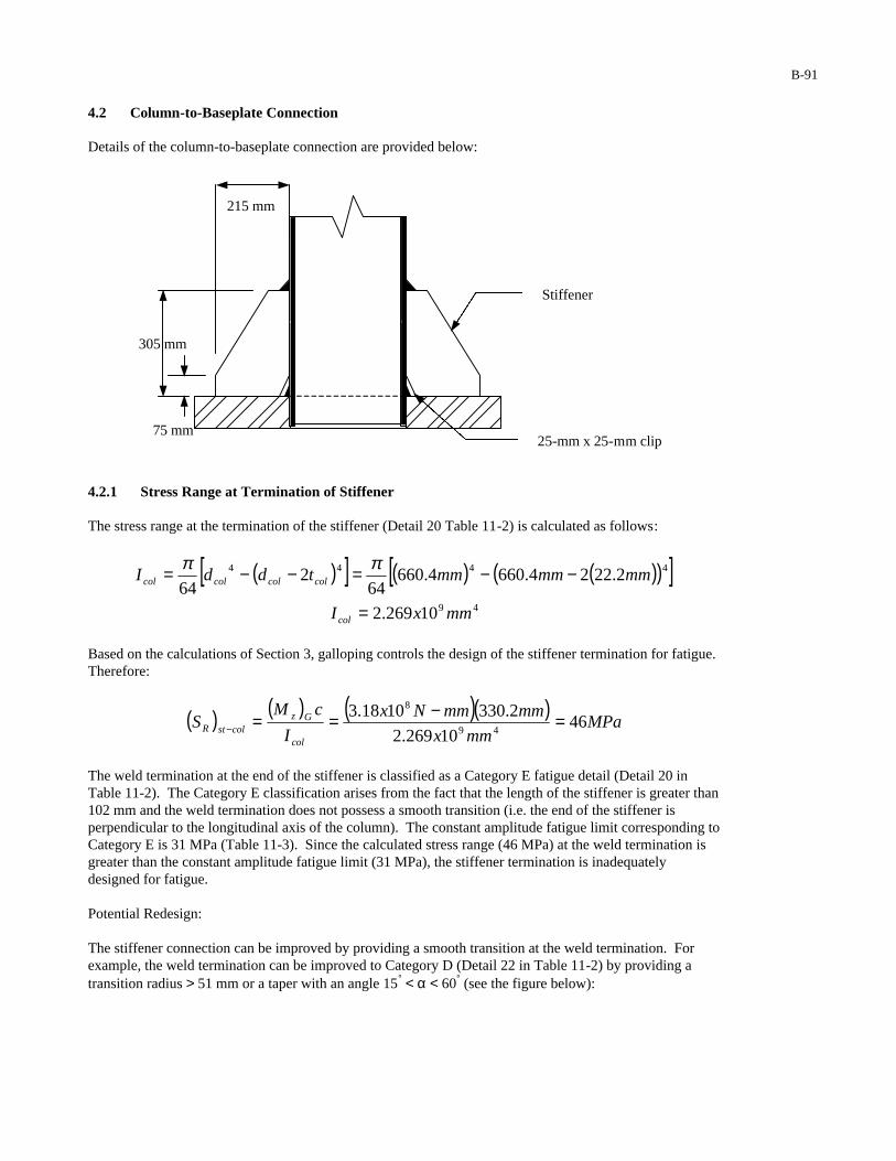
B-91
4.2 Column-to-Baseplate Connection Details of the column-to-baseplate connection are provided below:
4.2.1 Stress Range at Termination of Stiffener The stress range at the termination of the stiffener (Detail 20 Table 11-2) is calculated as follows:
( )[ ] ( ) ( )( )[ ]49
4444
10269.2
2.2224.6604.66064
264
mmxI
mmmmmmtddI
col
colcolcolcol
=
−−=−−= ππ
Based on the calculations of Section 3, galloping controls the design of the stiffener termination for fatigue. Therefore:
( ) ( ) ( )( )MPa
mmx
mmmmNx
I
cMS
col
GzcolstR 46
10269.2
2.3301018.349
8
=−==−
The weld termination at the end of the stiffener is classified as a Category E fatigue detail (Detail 20 in Table 11-2). The Category E classification arises from the fact that the length of the stiffener is greater than 102 mm and the weld termination does not possess a smooth transition (i.e. the end of the stiffener is perpendicular to the longitudinal axis of the column). The constant amplitude fatigue limit corresponding toCategory E is 31 MPa (Table 11-3). Since the calculated stress range (46 MPa) at the weld termination is greater than the constant amplitude fatigue limit (31 MPa), the stiffener termination is inadequately designed for fatigue. Potential Redesign: The stiffener connection can be improved by providing a smooth transition at the weld termination. For example, the weld termination can be improved to Category D (Detail 22 in Table 11-2) by providing a transition radius > 51 mm or a taper with an angle 15° < α < 60° (see the figure below):
215 mm
305 mm
75 mm
Stiffener
25-mm x 25-mm clip
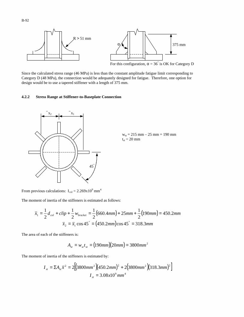
B-92
For this configuration, α = 36° is OK for Category D
Since the calculated stress range (46 MPa) is less than the constant amplitude fatigue limit corresponding to Category D (48 MPa), the connection would be adequately designed for fatigue. Therefore, one option for design would be to use a tapered stiffener with a length of 375 mm.
4.2.2 Stress Range at Stiffener-to-Baseplate Connection
wst = 215 mm – 25 mm = 190 mm tst = 20 mm
From previous calculations: Icol = 2.269x109 mm4
The moment of inertia of the stiffeners is estimated as follows:
( ) ( )
( ) mmmmxx
mmmmmmmmwclipdx bracketcol
3.31845cos2.45045cos
2.4501902
1254.660
2
1
2
1
2
1
12
1
===
=++=++=
°°
The area of each of the stiffeners is:
( )( ) 2380020190 mmmmmmtwA ststst ===
The moment of inertia of the stiffeners is estimated by:
( )( ) ( )( )[ ]49
22222
1008.3
3.318380022.45038002
mmxI
mmmmmmmmxAI
st
stst
=
+=Σ=
45°
x2 x1
R > 51 mm
α 375 mm
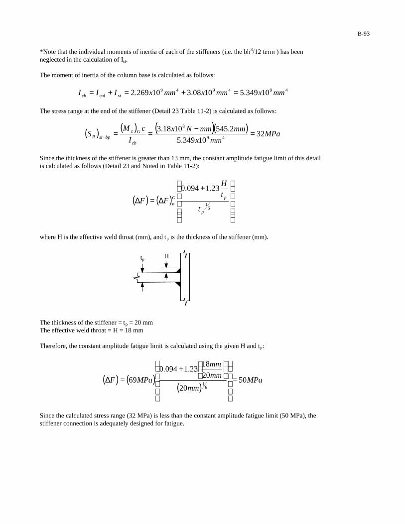
B-93
*Note that the individual moments of inertia of each of the stiffeners (i.e. the bh3/12 term ) has been neglected in the calculation of Ist. The moment of inertia of the column base is calculated as follows:
494949 10349.51008.310269.2 mmxmmxmmxIII stcolcb =+=+=
The stress range at the end of the stiffener (Detail 23 Table 11-2) is calculated as follows:
( ) ( ) ( )( )MPa
mmx
mmmmNx
I
cMS
cb
GzbpstR 32
10349.5
2.5451018.349
8
=−==−
Since the thickness of the stiffener is greater than 13 mm, the constant amplitude fatigue limit of this detail is calculated as follows (Detail 23 and Noted in Table 11-2):
( ) ( )
+∆=∆
61
23.1094.0
p
pCn
t
t
H
FF
where H is the effective weld throat (mm), and tp is the thickness of the stiffener (mm).
The thickness of the stiffener = tp = 20 mm The effective weld throat = H = 18 mm Therefore, the constant amplitude fatigue limit is calculated using the given H and tp:
( ) ( )( )
MPamm
mm
mm
MPaF 5020
20
1823.1094.0
696
1=
+
=∆
Since the calculated stress range (32 MPa) is less than the constant amplitude fatigue limit (50 MPa), the stiffener connection is adequately designed for fatigue.
H tp
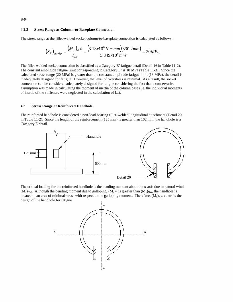
B-94
4.2.3 Stress Range at Column-to-Baseplate Connection The stress range at the fillet-welded socket column-to-baseplate connection is calculated as follows:
( ) ( ) ( )( )MPa
mmx
mmmmNx
I
cMS
cb
GzbpcolR 20
10349.5
2.3301018.349
8
=−==−
The fillet-welded socket connection is classified as a Category E’ fatigue detail (Detail 16 in Table 11-2). The constant amplitude fatigue limit corresponding to Category E’ is 18 MPa (Table 11-3). Since the calculated stress range (20 MPa) is greater than the constant amplitude fatigue limit (18 MPa), the detail is inadequately designed for fatigue. However, the level of overstress is minimal. As a result, the socket connection can be considered adequately designed for fatigue considering the fact that a conservative assumption was made in calculating the moment of inertia of the column base (i.e. the individual moments of inertia of the stiffeners were neglected in the calculation of Icb). 4.3 Stress Range at Reinforced Handhole The reinforced handhole is considered a non-load bearing fillet-welded longitudinal attachment (Detail 20 in Table 11-2). Since the length of the reinforcement (125 mm) is greater than 102 mm, the handhole is a Category E detail.
The critical loading for the reinforced handhole is the bending moment about the x-axis due to natural wind (Mx)NW. Although the bending moment due to galloping (Mz)G is greater than (Mx)NW, the handhole is located in an area of minimal stress with respect to the galloping moment. Therefore, (Mx)NW controls the design of the handhole for fatigue.
z
x x
z
Detail 20
125 mm
600 mm
Handhole
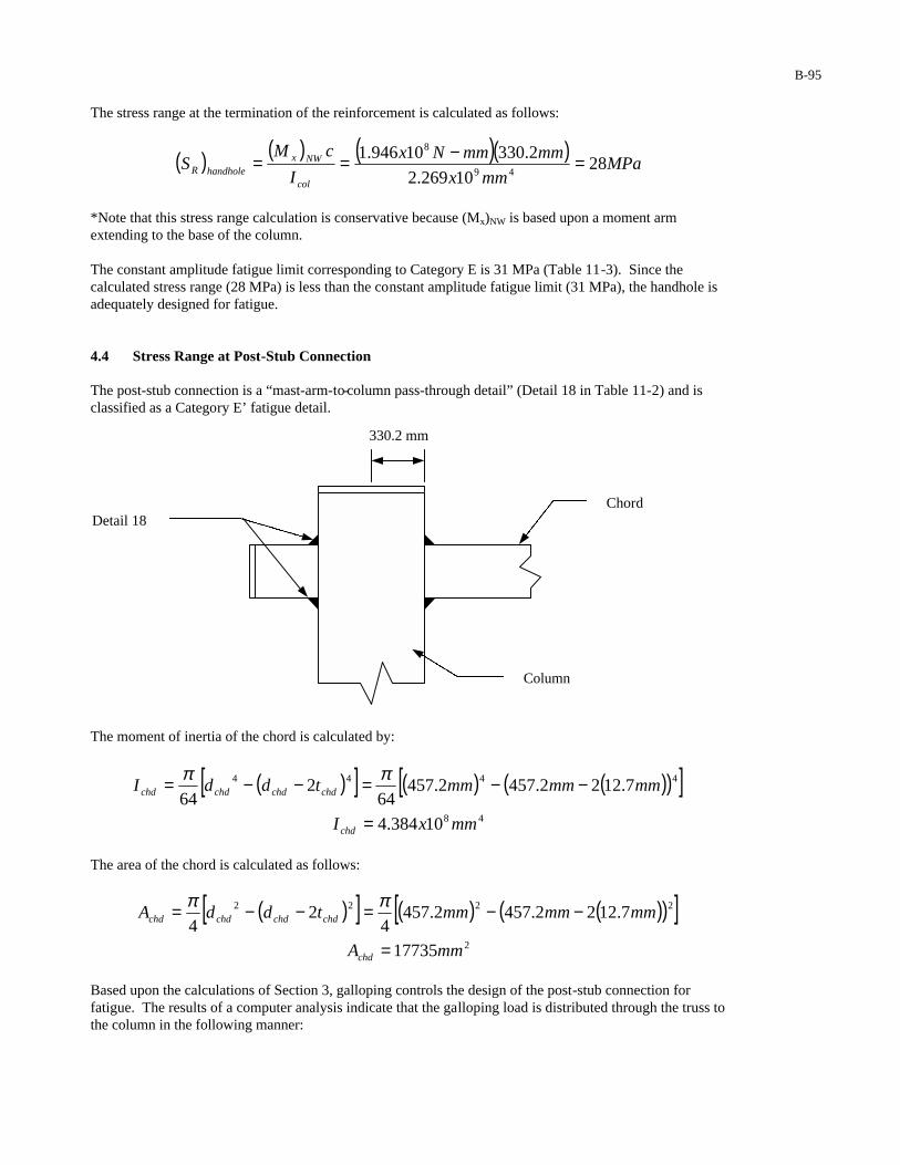
B-95
The stress range at the termination of the reinforcement is calculated as follows:
( ) ( ) ( )( )MPa
mmx
mmmmNx
I
cMS
col
NWxhandholeR 28
10269.2
2.33010946.149
8
=−==
*Note that this stress range calculation is conservative because (Mx)NW is based upon a moment arm extending to the base of the column. The constant amplitude fatigue limit corresponding to Category E is 31 MPa (Table 11-3). Since the calculated stress range (28 MPa) is less than the constant amplitude fatigue limit (31 MPa), the handhole is adequately designed for fatigue.
4.4 Stress Range at Post-Stub Connection The post-stub connection is a “mast-arm-to-column pass-through detail” (Detail 18 in Table 11-2) and is classified as a Category E’ fatigue detail.
The moment of inertia of the chord is calculated by:
( )[ ] ( ) ( )( )[ ]48
4444
10384.4
7.1222.4572.45764
264
mmxI
mmmmmmtddI
chd
chdchdchdchd
=
−−=−−= ππ
The area of the chord is calculated as follows:
( )[ ] ( ) ( )( )[ ]2
2222
17735
7.1222.4572.4574
24
mmA
mmmmmmtddA
chd
chdchdchdchd
=
−−=−−= ππ
Based upon the calculations of Section 3, galloping controls the design of the post-stub connection for fatigue. The results of a computer analysis indicate that the galloping load is distributed through the truss to the column in the following manner:
Chord
Column
Detail 18
330.2 mm
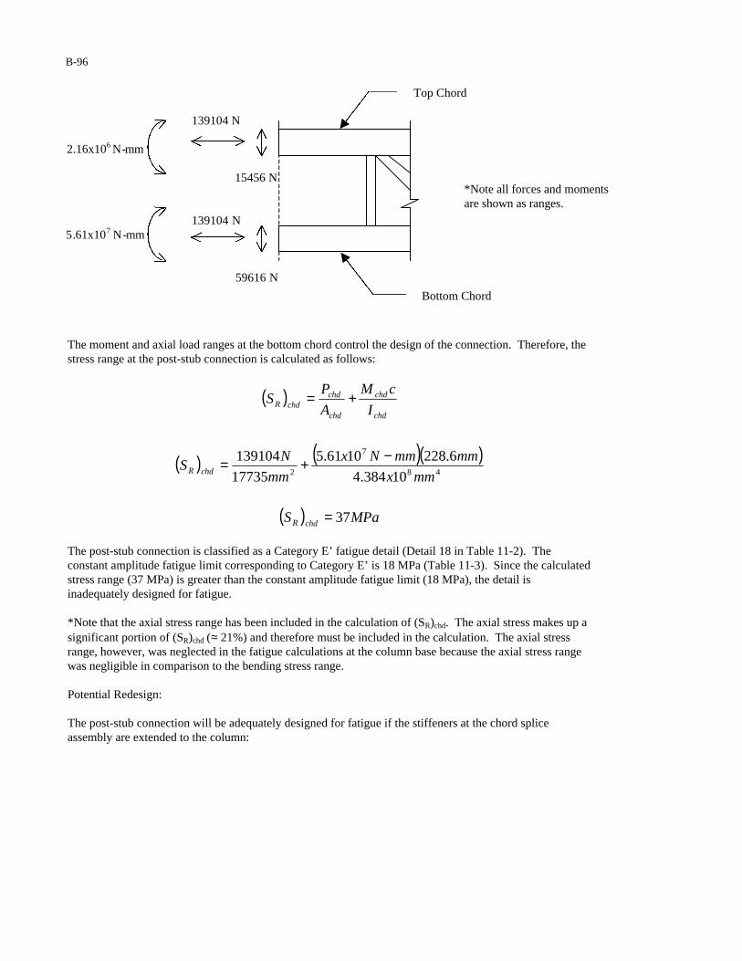
B-96
The moment and axial load ranges at the bottom chord control the design of the connection. Therefore, the stress range at the post-stub connection is calculated as follows:
( )
( ) ( )( )
( ) MPaS
mmx
mmmmNx
mm
NS
I
cM
A
PS
chdR
chdR
chd
chd
chd
chdchdR
37
10384.4
6.2281061.5
17735
13910448
7
2
=
−+=
+=
The post-stub connection is classified as a Category E’ fatigue detail (Detail 18 in Table 11-2). The constant amplitude fatigue limit corresponding to Category E’ is 18 MPa (Table 11-3). Since the calculated stress range (37 MPa) is greater than the constant amplitude fatigue limit (18 MPa), the detail is inadequately designed for fatigue. *Note that the axial stress range has been included in the calculation of (SR)chd. The axial stress makes up a significant portion of (SR)chd (≈ 21%) and therefore must be included in the calculation. The axial stress range, however, was neglected in the fatigue calculations at the column base because the axial stress range was negligible in comparison to the bending stress range. Potential Redesign: The post-stub connection will be adequately designed for fatigue if the stiffeners at the chord splice assembly are extended to the column:
139104 N
2.16x10⁶ N-mm
15456 N
139104 N 5.61x10⁷ N-mm
59616 N
Top Chord
Bottom Chord
*Note all forces and moments are shown as ranges.
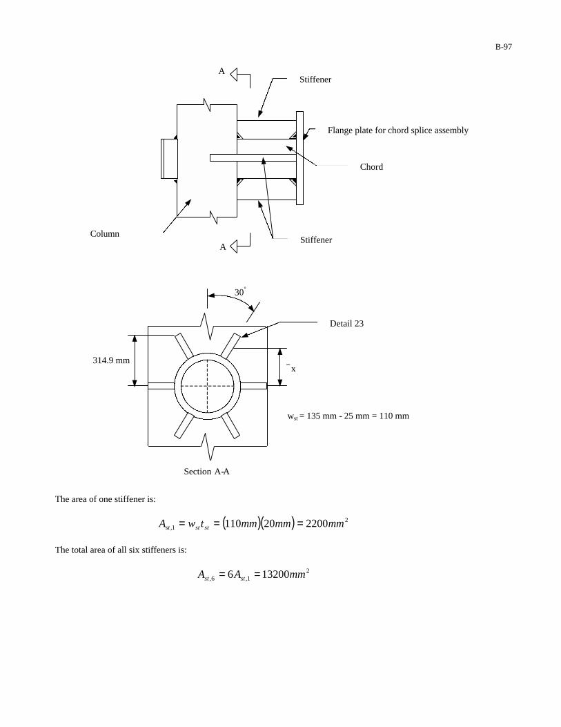
B-97
The area of one stiffener is:
( )( ) 21, 220020110 mmmmmmtwA ststst ===
The total area of all six stiffeners is:
21,6, 132006 mmAA stst ==
Stiffener
Flange plate for chord splice assembly
Chord
Stiffener Column
A
A
30°
314.9 mm
Detail 23
x
wst = 135 mm - 25 mm = 110 mm
Section A-A

B-98
The moment of inertia of the stiffeners is estimated by:
( ) ( )
mmx
mmmmmmwclipdx stchd
3.267
30cos1102
1252.457
2
130cos
2
1
2
1
=
++=
++= °°
( )( )[ ] 482221, 10288.63.26722004 mmxmmmmxAI stst ==Σ=
*Note that the moments of inertia of each of the individual stiffeners (i.e. the bh 3/12 term) have been neglected in the calculation of Ist . The moment of inertia of the flange plate assembly is:
( ) ( ) 494848 10067.110288.610384.4 mmxmmxmmxIII stchdFP =+=+=
The area of the flange plate assembly is:
( ) ( ) 2226, 309351320017735 mmmmmmAAA stchdFP =+=+=
The stress range at the post-stub connection is calculated as follows:
( ) ( )( )
( ) MPaS
mmx
mmmmNx
mm
N
I
cM
A
PS
chdR
FP
chdchd
FP
chdchdR
17
10067.1
6.2281061.5
30935
13910449
7
2
=
−+=+=
Since the calculated stress range (17 MPa) is now less than the constant amplitude fatigue limit corresponding to a Category E’ fatigue detail (18 MPa), the post-stub connection is adequately designed for fatigue. The stress range at the stiffener-to-column connection (Detail 23 Table 11-2) is calculated as follows:
( ) ( )( )
( ) MPaS
mmx
mmmmMx
mm
N
I
cM
A
PS
colstR
FP
stchd
FP
chdcolstR
21
10067.1
9.3141061.5
30935
13910449
7
2
=
−+=+=
−
−
Since the thickness of the stiffener is greater than 13 mm, the constant amplitude fatigue limit of this detail is calculated as follows:
( ) ( )
+∆=∆
61
23.1094.0
p
pCn
t
t
H
FF

B-99
where H is the effective weld throat (mm) and tp is the thickness of the stiffener (mm). Therefore, the CAFL is calculated as follows:
( ) ( )( )
MPamm
mm
mm
MPaF 4820
20
1723.1094.0
696
1=
+
=∆
Since the calculated stress range (21 MPa) is less than the constant amplitude fatigue limit (48 MPa), the stiffener-to-column connection is adequately designed for fatigue.
4.5 Chord Splice Assembly
Details of the chord splice assembly are shown below:
135 mm
230 mm
25-mm x 25-mm clip
Stiffener
Detail 20
Detail 16
Detail 23
30°
15°
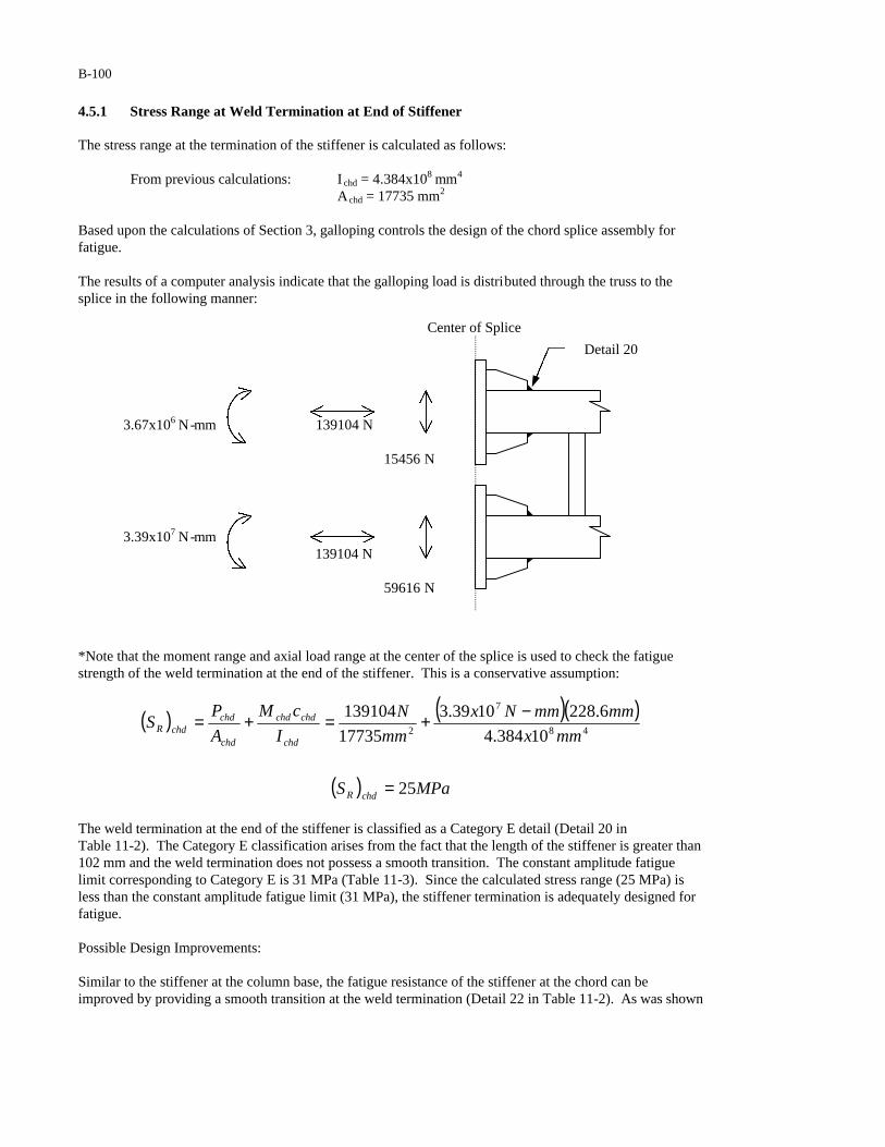
B-100
4.5.1 Stress Range at Weld Termination at End of Stiffener The stress range at the termination of the stiffener is calculated as follows:
From previous calculations: I chd = 4.384x108 mm4 Achd = 17735 mm2 Based upon the calculations of Section 3, galloping controls the design of the chord splice assembly for fatigue. The results of a computer analysis indicate that the galloping load is distributed through the truss to the splice in the following manner: *Note that the moment range and axial load range at the center of the splice is used to check the fatigue strength of the weld termination at the end of the stiffener. This is a conservative assumption:
( ) ( )( )
( ) MPaS
mmx
mmmmNx
mm
N
I
cM
A
PS
chdR
chd
chdchd
chd
chdchdR
25
10384.4
6.2281039.3
17735
13910448
7
2
=
−+=+=
The weld termination at the end of the stiffener is classified as a Category E detail (Detail 20 in Table 11-2). The Category E classification arises from the fact that the length of the stiffener is greater than 102 mm and the weld termination does not possess a smooth transition. The constant amplitude fatigue limit corresponding to Category E is 31 MPa (Table 11-3). Since the calculated stress range (25 MPa) is less than the constant amplitude fatigue limit (31 MPa), the stiffener termination is adequately designed for fatigue. Possible Design Improvements: Similar to the stiffener at the column base, the fatigue resistance of the stiffener at the chord can be improved by providing a smooth transition at the weld termination (Detail 22 in Table 11-2). As was shown
3.67x10⁶ N-mm 139104 N 15456 N
3.39x10⁷ N-mm 139104 N 59616 N
Detail 20
Center of Splice
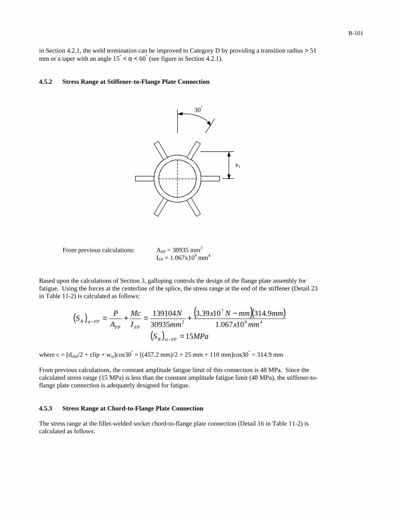
B-101
in Section 4.2.1, the weld termination can be improved to Category D by providing a transition radius > 51 mm or a taper with an angle 15° < α < 60° (see figure in Section 4.2.1). 4.5.2 Stress Range at Stiffener-to-Flange Plate Connection
From previous calculations: AFP = 30935 mm2
IFP = 1.067x109 mm4
Based upon the calculations of Section 3, galloping controls the design of the flange plate assembly for fatigue. Using the forces at the centerline of the splice, the stress range at the end of the stiffener (Detail 23 in Table 11-2) is calculated as follows:
( ) ( )( )
( ) MPaS
mmx
mmmmNx
mm
N
I
Mc
A
PS
FPstR
FPFPFPstR
15
10067.1
9.3141039.3
30935
13910449
7
2
=
−+=+=
−
−
where c = [dchd/2 + clip + wst]cos30° = [(457.2 mm)/2 + 25 mm + 110 mm]cos30° = 314.9 mm From previous calculations, the constant amplitude fatigue limit of this connection is 48 MPa. Since the calculated stress range (15 MPa) is less than the constant amplitude fatigue limit (48 MPa), the stiffener-to-flange plate connection is adequately designed for fatigue. 4.5.3 Stress Range at Chord-to-Flange Plate Connection The stress range at the fillet-welded socket chord-to-flange plate connection (Detail 16 in Table 11-2) is calculated as follows:
30°
x1
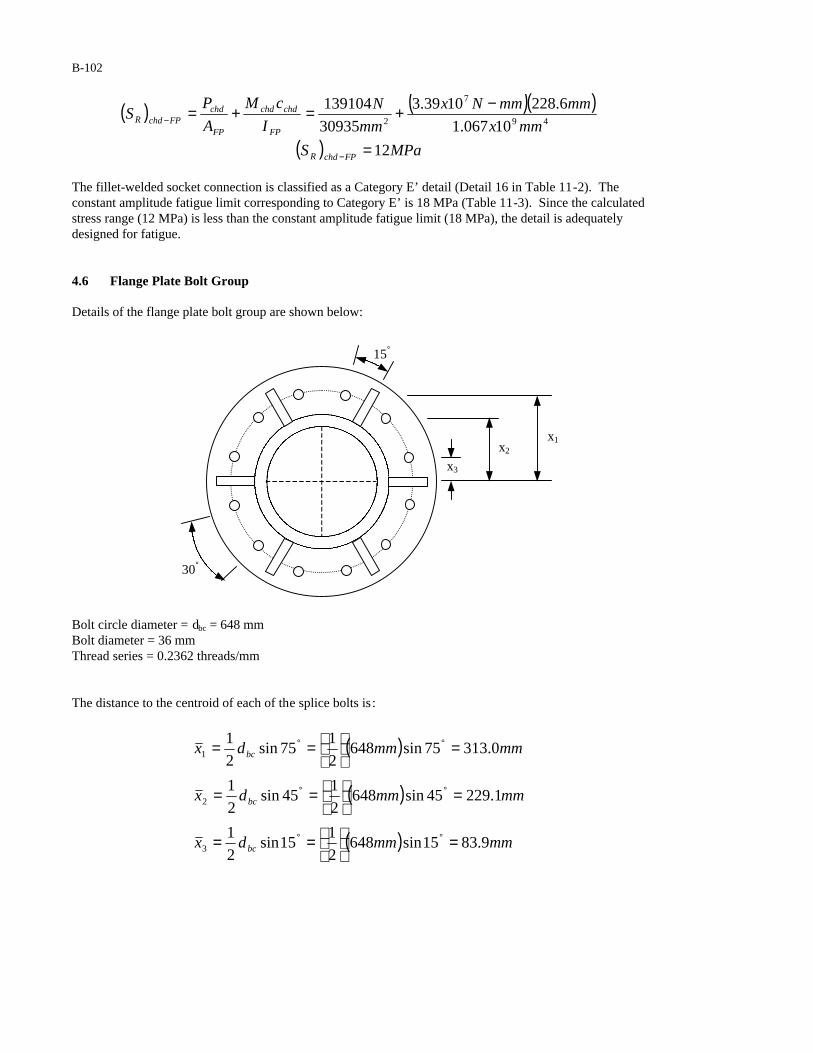
B-102
( ) ( )( )
( ) MPaS
mmx
mmmmNx
mm
N
I
cM
A
PS
FPchdR
FP
chdchd
FP
chdFPchdR
12
10067.1
6.2281039.3
30935
13910449
7
2
=
−+=+=
−
−
The fillet-welded socket connection is classified as a Category E’ detail (Detail 16 in Table 11-2). The constant amplitude fatigue limit corresponding to Category E’ is 18 MPa (Table 11-3). Since the calculated stress range (12 MPa) is less than the constant amplitude fatigue limit (18 MPa), the detail is adequately designed for fatigue.
4.6 Flange Plate Bolt Group
Details of the flange plate bolt group are shown below:
Bolt circle diameter = dbc = 648 mm Bolt diameter = 36 mm Thread series = 0.2362 threads/mm
The distance to the centroid of each of the splice bolts is:
( )
( )
( ) mmmmdx
mmmmdx
mmmmdx
bc
bc
bc
9.8315sin6482
115sin
2
1
1.22945sin6482
145sin
2
1
0.31375sin6482
175sin
2
1
3
2
1
=
==
=
==
=
==
°°
°°
°°
15°
30°
x2
x1
x3
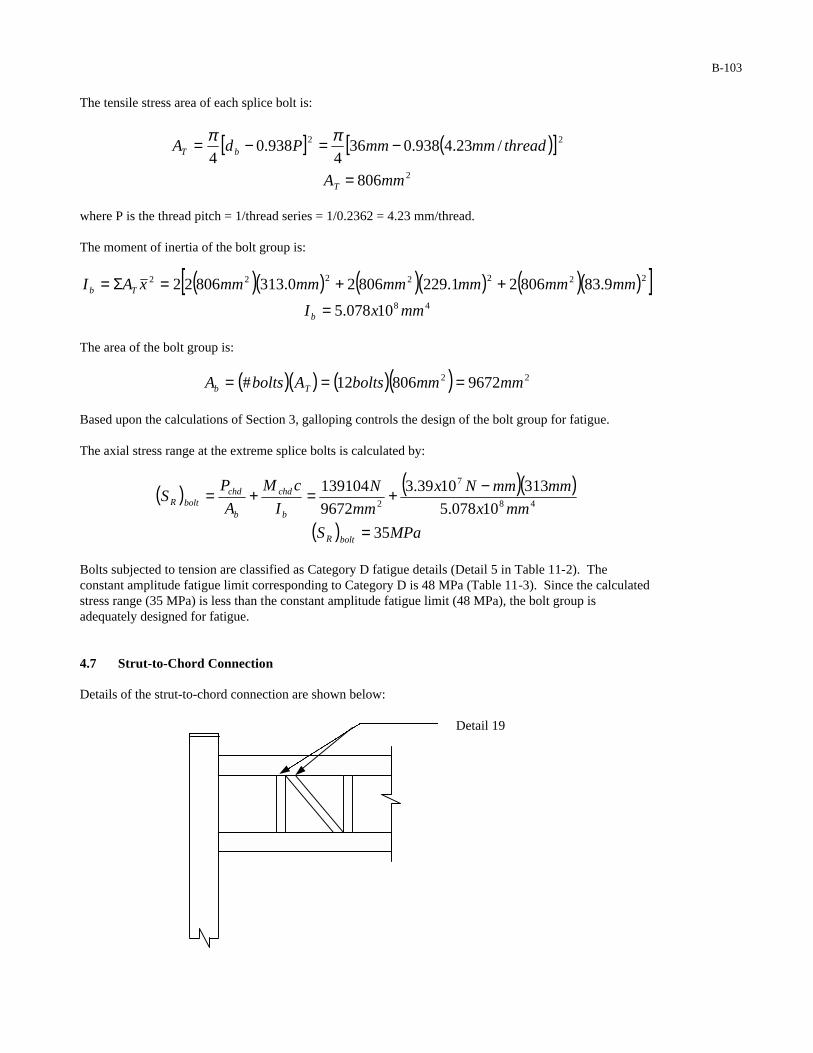
B-103
The tensile stress area of each splice bolt is:
[ ] ( )[ ]2
22
806
/23.4938.0364
938.04
mmA
threadmmmmPdA
T
bT
=
−=−= ππ
where P is the thread pitch = 1/thread series = 1/0.2362 = 4.23 mm/thread. The moment of inertia of the bolt group is:
( )( ) ( )( ) ( )( )[ ]48
2222222
10078.5
9.8380621.22980620.31380622
mmxI
mmmmmmmmmmmmxAI
b
Tb
=
++=Σ=
The area of the bolt group is:
( )( ) ( )( ) 22 967280612# mmmmboltsAboltsA Tb ===
Based upon the calculations of Section 3, galloping controls the design of the bolt group for fatigue. The axial stress range at the extreme splice bolts is calculated by:
( ) ( )( )
( ) MPaS
mmx
mmmmNx
mm
N
I
cM
A
PS
boltR
b
chd
b
chdboltR
35
10078.5
3131039.3
9672
13910448
7
2
=
−+=+=
Bolts subjected to tension are classified as Category D fatigue details (Detail 5 in Table 11-2). The constant amplitude fatigue limit corresponding to Category D is 48 MPa (Table 11-3). Since the calculated stress range (35 MPa) is less than the constant amplitude fatigue limit (48 MPa), the bolt group is adequately designed for fatigue. 4.7 Strut-to-Chord Connection Details of the strut-to-chord connection are shown below:
Detail 19

B-104
The moment of inertia of the strut is:
( )[ ] ( ) ( )( )[ ]46
4444
10586.8
5.923.1413.14164
264
mmxI
mmtddI
strut
strutstrutstrutstrut
=
−−=−−= ππ
The area of the strut is:
( )[ ] ( ) ( )( )[ ]2
2222
3934
5.923.1413.1414
24
mmA
mmmmtddA
strut
strutstrutstrutstrut
=
−−=−−= ππ
Based upon calculations of Section 3, galloping controls the design of the strut-to-chord connection for fatigue. The results of a computer analysis indicate that the maximum forces occur in the first vertical strut from the face of the column. Therefore, this strut will be used to check the adequacy of the strut-to-chord connection for fatigue.
The forces carried by the first strut are as follows:
Axial load range = 55200 N Bending moment range = 8.832 x 10⁵ N-mm
The stress range at the strut-to-chord connection is calculated by:
( ) ( )( )
( ) MPaS
mmx
mmmmNx
mm
N
I
cM
A
PS
chdstrutR
strut
strut
strut
strutchdstrutR
21
10586.8
65.7010832.8
3934
5520046
5
2
=
−+=+=
−
−
The r/t ratio for the chord is:
( ) 187.12
6.228 ==mm
mmt
rchd
Since the r/t ratio of the chord is less than 24, the strut-to-chord connection (Detail 19 in Table 11-2) is classified as Category ET with respect to the stress range in the strut. The constant amplitude fatigue limit for Category ET is 8 MPa (Table 11-3). Since the calculated stress range (21 MPa) is greater than the constant amplitude fatigue limit (8 MPa), the strut-to-chord connection is inadequately designed for fatigue.

B-105
Potential Redesigns: 1. Try using a strut with a 323.9-mm diameter and a 9.5-mm thickness.
The moment of inertia of the strut would be:
( )[ ] ( ) ( )( )[ ]
][
48
4444
1016.1
5.929.3239.32364
264
mmxI
mmtddI
strut
strutstrutstrutstrut
=
−−=−−= ππ
The area of the strut would be:
( )[ ] ( ) ( )( )2
2222
9383
5.929.3239.3234
24
mmA
mmmmtddA
strut
strutstrutstrutstrut
=
−−=−−= ππ
The stress range at the strut-to-chord connection is calculated by:
( ) ( )( )
( ) MPaS
mmx
mmmmNx
mm
N
I
cM
A
PS
chdstrutR
strut
strut
strut
strutchdstrutR
7
1016.1
16210832.8
9383
5520048
5
2
=
−+=+=
−
−
Since the calculated stress range (7 MPa) is less then the CAFL for Category ET (8 MPa), the strut-to-chord connection will be adequately designed for fatigue using a strut with a diameter = 323.9 mm and a thickness = 9.5 mm. 2. Connect the struts and diagonals to the chords using gusset plates. For this connection, try a 425-mm long by 20-mm thick gusset plate. This detail is Category ET.
The area of the gusset plate is:
( )( ) 2850020425 mmmmmmtLA gussetgussetgusset ===
The moment of inertia of the gusset plate is:
( )( ) ( )( ) 4833
1028.112
42520
12mmx
mmmmLtI gussetgusset
gusset ===
The stress range in the gusset plate is:
( ) ( )( )
( ) MPaS
mmx
mmmmNx
mm
NS
gussetR
gussetR
8
1028.1
5.21210832.8
8500
5520048
5
2
=
−+=
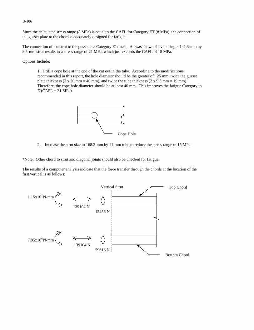
B-106
Since the calculated stress range (8 MPa) is equal to the CAFL for Category ET (8 MPa), the connection of the gusset plate to the chord is adequately designed for fatigue. The connection of the strut to the gusset is a Category E’ detail. As was shown above, using a 141.3-mm by 9.5-mm strut results in a stress range of 21 MPa, which just exceeds the CAFL of 18 MPa. Options Include:
1. Drill a cope hole at the end of the cut out in the tube. According to the modifications recommended in this report, the hole diameter should be the greater of: 25 mm, twice the gusset plate thickness (2 x 20 mm = 40 mm), and twice the tube thickness (2 x 9.5 mm = 19 mm). Therefore, the cope hole diameter should be at least 40 mm. This improves the fatigue Category to E (CAFL = 31 MPa).
2. Increase the strut size to 168.3-mm by 11-mm tube to reduce the stress range to 15 MPa.
*Note: Other chord to strut and diagonal joints should also be checked for fatigue. The results of a computer analysis indicate that the force transfer through the chords at the location of the first vertical is as follows:
Cope Hole
1.15x10⁷N-mm
139104 N 15456 N
7.95x10⁶N-mm 139104 N
59616 N
Top Chord
Bottom Chord
Vertical Strut

B-107
The stress range in the chord at the location of the first vertical strut is:
( ) ( )( )
( ) MPaS
mmx
mmmmNx
mm
N
I
cM
A
PS
strutchdR
chd
chdchd
chd
chdstrutchdR
14
10384.4
6.2291015.1
17735
13910448
7
2
=
−+=+=
−
−
The strut-to-chord connection is classified as a Category E detail with respect to the stress range in the chord. The constant amplitude fatigue limit for Category E is 31 MPa (Table 11-3). Since the calculated stress range (14 MPa) is less than the CAFL (31 MPa), the strut-to-chord connection is adequately designedfor fatigue with respect to the stress range in the chord.
5 DEFLECTION As per the requirements of Section 11.8, cantilevered sign support structures with trussed mast-arms need not be designed to satisfy the deflection limit state.
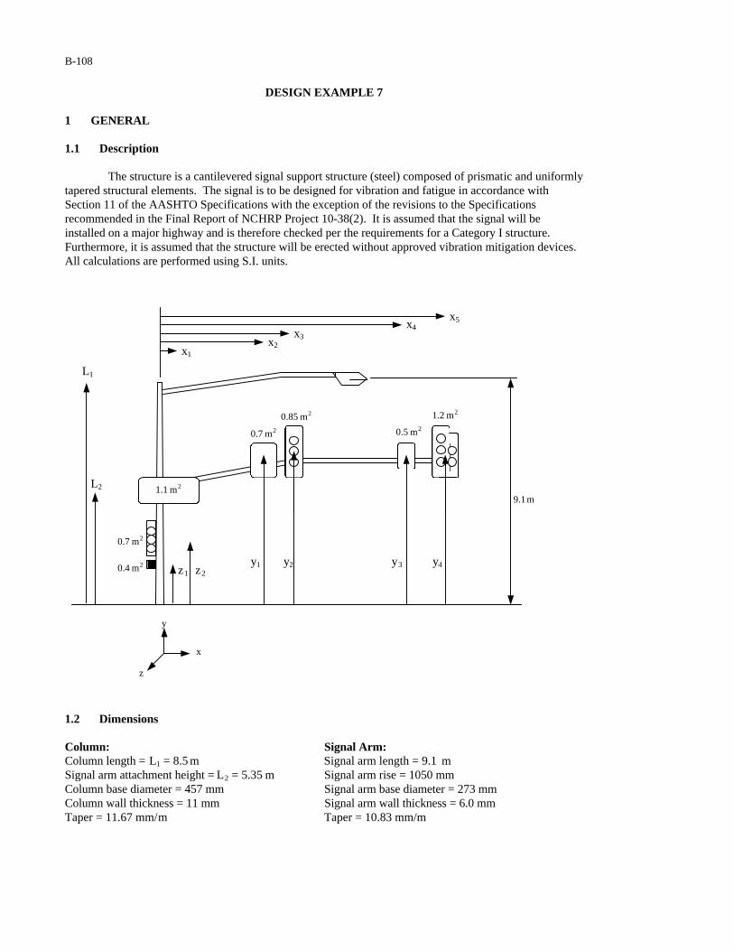
B-108
DESIGN EXAMPLE 7 1 GENERAL 1.1 Description The structure is a cantilevered signal support structure (steel) composed of prismatic and uniformly tapered structural elements. The signal is to be designed for vibration and fatigue in accordance with Section 11 of the AASHTO Specifications with the exception of the revisions to the Specifications recommended in the Final Report of NCHRP Project 10-38(2). It is assumed that the signal will be installed on a major highway and is therefore checked per the requirements for a Category I structure. Furthermore, it is assumed that the structure will be erected without approved vibration mitigation devices. All calculations are performed using S.I. units.
1.2 Dimensions Column: Signal Arm: Column length = L1 = 8.5 m Signal arm length = 9.1 m Signal arm attachment height = L2 = 5.35 m Signal arm rise = 1050 mm Column base diameter = 457 mm Signal arm base diameter = 273 mm Column wall thickness = 11 mm Signal arm wall thickness = 6.0 mm Taper = 11.67 mm/m Taper = 10.83 mm/m
y
z1 z2
0.7 m2 0.5 m2
9.1 m
0.7 m2
L1
y1 y2 y3 y4
1.2 m2
L2 1.1 m2
0.4 m2
0.85 m2
z
x
x3 x4
x5
x2 x1

B-109
Luminaire Extension: Anchor Rods: Luminaire arm length = 5.5 m Anchor rod circle diameter = 610 mm Luminaire arm diameter = 120 mm Anchor rod diameter = 44.5 mm Luminaire wall thickness = 6.0 mm Luminaire arm rise = 1219 mm Distances to Attachments: Distance from column to center of sign 1 = x1 = 0.45 m Distance from column to center of sign 2 = x2 = 5.0 m Distance from column to center of signal 2 = x3 = 5.6 m Distance from column to center of sign 3 = x4 = 8.5 m Distance from column to center of signal 3 = x5 = 9.1 m Height to center of signal 1.1 = z1 = 3.18 m Height to center of signal 1 = z2 = 3.89 m Height to center of sign 2, sign 3, signal 2, and signal 3 = y = y1 = y2 = y3 = y4 = 6.4 m
1.3 Critical Fatigue Details The structure contains the following details, which must be checked for fatigue. 1. Anchor rods (Detail 5 in Table 11-2) 2. Column-to-baseplate fillet-welded connection (Detail 16 in Table 11-2) 3. Signal mast-arm-to-column connection (Details 5, 16, and 17 in Table 11-2) 4. Luminaire mast-arm-to-column connection (Details 5, 16, 17, and 19 in Table 11-2)
2 CALCULATION OF LIMIT STATE FATIGUE LOADS 2.1 Galloping The equivalent static shear range to be applied to each of the signal and sign attachments is calculated in accordance with Equation 11-1:
( ) ( ) PaIP FG 10000.110001000 ===
where IF = 1.0 (Table 11-1) is the importance factor used in the design of a Category I signal support structure for galloping. The equivalent static shear load ranges to be applied to each of the signals and signs attached to the signal arm are calculated by:
( ) ( ) NmPaAPFvsignGsignG 11001.11000 2
11, ===
( ) ( ) NmPaAPFvsignGsignG 7007.01000 2
22, ===
( ) ( ) NmPaAPFvsignalGsignalG 85085.01000 2
22, ===
( ) ( ) NmPaAPFvsignGsignG 5005.01000 2
33, ===
( ) ( ) NmPaAPFvsignalGsignalG 12002.11000 2
33, ===
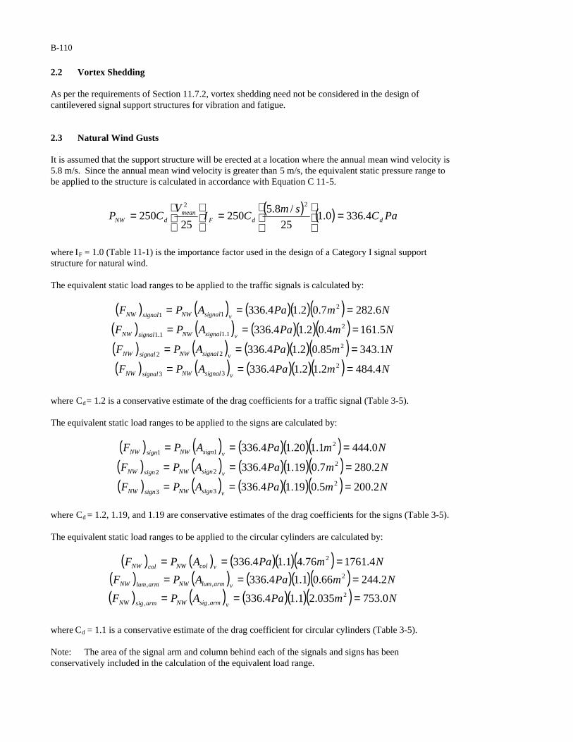
B-110
2.2 Vortex Shedding As per the requirements of Section 11.7.2, vortex shedding need not be considered in the design of cantilevered signal support structures for vibration and fatigue.
2.3 Natural Wind Gusts It is assumed that the support structure will be erected at a location where the annual mean wind velocity is 5.8 m/s. Since the annual mean wind velocity is greater than 5 m/s, the equivalent static pressure range to be applied to the structure is calculated in accordance with Equation C 11-5.
( ) ( ) PaCsm
CIV
CP ddFmean
dNW 4.3360.125
/8.5250
25250
22
=
=
=
where IF = 1.0 (Table 11-1) is the importance factor used in the design of a Category I signal support structure for natural wind. The equivalent static load ranges to be applied to the traffic signals is calculated by:
( ) ( ) ( )( )( ) NmPaAPFvsignalNWsignalNW 6.2827.02.14.336 2
11 ===
( ) ( ) ( )( )( ) NmPaAPFvsignalNWsignalNW 5.1614.02.14.336 2
1.11.1 ===
( ) ( ) ( )( )( ) NmPaAPFvsignalNWsignalNW 1.34385.02.14.336 2
22 ===
( ) ( ) ( )( )( ) NmPaAPFvsignalNWsignalNW 4.4842.12.14.336 2
33 ===
where Cd = 1.2 is a conservative estimate of the drag coefficients for a traffic signal (Table 3-5). The equivalent static load ranges to be applied to the signs are calculated by:
( ) ( ) ( )( )( ) NmPaAPFvsignNWsignNW 0.4441.120.14.336 2
11 ===
( ) ( ) ( )( )( ) NmPaAPFvsignNWsignNW 2.2807.019.14.336 2
22 ===
( ) ( ) ( )( )( ) NmPaAPFvsignNWsignNW 2.2005.019.14.336 2
33 ===
where Cd = 1.2, 1.19, and 1.19 are conservative estimates of the drag coefficients for the signs (Table 3-5). The equivalent static load ranges to be applied to the circular cylinders are calculated by:
( ) ( ) ( )( )( ) NmPaAPF vcolNWcolNW 4.176176.41.14.336 2 ===
( ) ( ) ( )( )( ) NmPaAPFvarmlumNWarmlumNW 2.24466.01.14.336 2
,, ===
( ) ( ) ( )( )( ) NmPaAPFvarmsigNWarmsigNW 0.753035.21.14.336 2
,, ===
where Cd = 1.1 is a conservative estimate of the drag coefficient for circular cylinders (Table 3-5). Note: The area of the signal arm and column behind each of the signals and signs has been conservatively included in the calculation of the equivalent load range.

B-111
2.4 Truck Gusts It is assumed that the support structure will be erected at a location where the posted speed limit is not significantly less than 30 m/s. Therefore, equation 11-6 (revised) is applied without modification. The maximum equivalent static pressure range to be applied to a structure is calculated in accordance with the modified version of Equation 11-6 recommended in this report:
( ) PaCCICP ddFdTG 9000.1900900 ===
where IF = 1.0 (Table 11-1) is the importance factor used in the design of a Category I signal support structure for truck gusts. As per the recommended revisions to Section 11.7.4, truck gust pressures decrease linearly between elevations of 6 and 10 m. For this example, it is assumed that the base of the column is at the same elevation as the roadway surface. The centers of gravity of the mast arm tip and its attachments are located at an elevation of 6.4 m. However, both signals hang below that elevation by at 0.4 m. Therefore, the full truck gust pressure equation will conservatively be used throughout. The equivalent static load range applied to the traffic signals and the outer 3.7 meters of the signal arm are calculated as follows:
( ) ( ) ( )( ) NmPaAPFhsignalTGsignalTG 1081.02.1900 2
22 ===
( ) ( ) ( )( ) NmPaAPFhsignalTGsignalTG 2162.02.1900 2
33 ===
( ) ( ) ( )( ) NmPaAPFharmsigTGarmsigTG 71372.01.1900 2
,, ===
where Cd = 1.2 and 1.1 are conservative estimates of the drag coefficient for the horizontal surface of the traffic signals and the signal arm, respectively (Table 3-5). All areas used are the corresponding areas that are projected on a horizontal plane. 3 CALCULATIONS OF BENDING MOMENTS 3.1 Moment Due to Galloping The bending moment at the centerline of the column (about the z-axis) is calculated by:
( ) ( ) ( ) ( ) ( ) ( ) ( ) ( ) ( ) ( ) ( )5343322211 xFxFxFxFxFM signalGsignGsignalGsignGsignGGz ++++=
( ) ( )( ) ( )( ) ( )( ) ( )( ) ( )( )mNmNmNmNmNM Gz 1.912005.85006.58500.570045.01100 ++++=( ) mNM Gz −= 925,23

B-112
3.2 Moment Due to Natural Wind The bending moment at the base of the column (about the x-axis) is calculated by:
( ) ( ) ( ) ( ) ( ) ( ) ( ) ( ) ( )21,,1 1.92/ zFyFmFLFM signalNWarmsigNWarmlumNWcolNWNWx +++=
( ) ( ) ( ) ( ) ( ) ( ) ( ) ( ) ( )[ ]33222111.1 signalNWsignNWsignalNWsignNWsignNWsignaNW FFFFyLFzF ++++++
( ) ( )( ) ( )( ) ( )( ) ( )( )mNmNmNmNM NWx 89.36.2824.60.7531.92.24425.44.1761 +++=
( )( ) ( )( ) ( )[ ]NNNNmmNmN 4.4842.2001.3432.2804.635.50.44418.35.161 ++++++
( ) mNM NWx −= 886,26
Note: It is conservatively assumed that the column load [(FNW)col] acts at the mid-height of the column and that the mast arm loads [(FNW)sig,arm and (FNW)lum,arm] act at the peak height of the mast arm.
The bending moment in the signal arm (about the y-axis) at pole connection is calculated by:
( ) ( ) ( ) ( ) ( ) ( ) ( )2211,,,2/1.9 xFxFmFM signNWsignNWarmsigNWarmsigNWy ++=
( ) ( ) ( ) ( ) ( ) ( )534332 xFxFxF signalNWsignNWsignalNW +++
( ) ( )( ) ( )( ) ( )( )mNmNmNM
armsigNWy 0.52.28045.00.44455.40.753,,
++=
( )( ) ( )( ) ( )( )mNmNmN 1.92.4845.82.2006.51.343 +++
( ) mNMarmsigNWy −= 056,13
,,
The bending moment in the luminaire arm (about the y-axis) at the pole connection is calculated by:
( ) ( ) ( ) ( )( ) mNmNmFM armlumNWarmlumNWy −=== 67275.22.2442/5.5,,,
Note: It is conservatively assumed that the loads on the luminaire and signal arms act at the horizontalmid-points of the arms and that the signal and crosswalk signal attached to the column need not be considered for these calculations.
3.3 Moment Due to Truck Gusts The bending moment at the centerline of the column (about the z-axis) is calculated by:
( ) ( ) ( ) ( ) ( ) ( ) ( )2/6.35,3253 mxFxFxFM armsigTGsignalTGsignalTGTGz −++=
( ) ( )( ) ( )( ) ( )( )2/7.31.97136.51081.9216 mmNmNmNM TGz −++=
( ) mNM TGz −= 775,7

B-113
4 STRESS RANGE CALCULATIONS 4.1 Anchor Rods Details of the anchor rods are provided below:
Thread pitch = P = 5.1 mm Anchor rod circle diameter = darc = 610 mm Nominal anchor rod diameter = dar = 44.5 mm Number of anchor rods = 4 4.1.1 Moment of Inertia of the Anchor Rod Group The centroidal distances to the anchor rods are calculated by:
mmd
x arc 216.045cos2
610.045cos
2=°=°=
where x is the centroidal distance to each of the anchor rods and darc = 0.610 m is the diameter of the anchor rod circle. The tensile stress area of each of the anchor rods is calculated using Equation 5-23:
[ ] ( )[ ] 222 12391.5938.05.444
938.04
mmmmmmPdA arT =−=−= ππ
where AT is the tensile stress area of each anchor rod, d ar = 44.5 mm is the nominal anchor rod diameter, and P = 5.1 mm is the thread pitch. The moment of inertia of the anchor rod group is calculated by:
( )( )[ ] 442232 1031.2216.010239.14 mmmxAI Tar−− ×=×=Σ=
where AT = 1.239 x 10⁻³ m2 is the tensile stress area of each anchor rod and x is the centroidal distance to each of the anchor rods.
x
Pole Base Diameter
Anchor Rod Circle
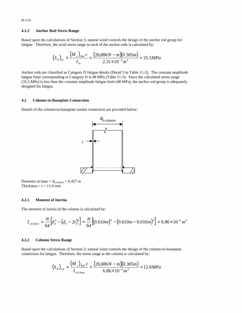
B-114
4.1.2 Anchor Rod Stress Range Based upon the calculations of Section 3, natural wind controls the design of the anchor rod group for fatigue. Therefore, the axial stress range in each of the anchor rods is calculated by:
( ) ( ) ( )( )MPa
m
mmN
I
cMS
ar
NWxarR 5.35
1031.2
305.0886,2644
=×−== −
Anchor rods are classified as Category D fatigue details (Detail 5 in Table 11-2). The constant amplitude fatigue limit corresponding to Category D is 48 MPa (Table 11-3). Since the calculated stress range (35.5 MPa) is less than the constant amplitude fatigue limit (48 MPa), the anchor rod group is adequately designed for fatigue. 4.2 Column-to-Baseplate Connection Details of the column-to-baseplate socket connection are provided below:
t
db,column
Diameter at base = db,column = 0.457 m Thickness = t = 11.0 mm 4.2.1 Moment of Inertia The moment of inertia of the column is calculated by:
( )[ ] ( ) ( )[ ] 444444, 1086.6016.0610.0610.0
642
64mmmmtddI bbbasecol
−×=−−=−−= ππ
4.2.2 Column Stress Range Based upon the calculations of Section 3, natural wind controls the design of the column-to-baseplate connection for fatigue. Therefore, the stress range at the column is calculated by:
( ) ( ) ( )( )MPa
m
mmN
I
cMS
basecol
NWxcolR 0.12
1086.6
305.0886,2644
,
=×−== −
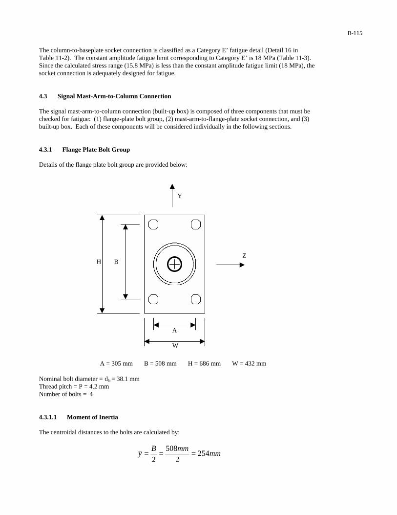
B-115
The column-to-baseplate socket connection is classified as a Category E’ fatigue detail (Detail 16 in Table 11-2). The constant amplitude fatigue limit corresponding to Category E’ is 18 MPa (Table 11-3). Since the calculated stress range (15.8 MPa) is less than the constant amplitude fatigue limit (18 MPa), the socket connection is adequately designed for fatigue.
4.3 Signal Mast-Arm-to-Column Connection
The signal mast-arm-to-column connection (built-up box) is composed of three components that must be checked for fatigue: (1) flange-plate bolt group, (2) mast-arm-to-flange-plate socket connection, and (3) built-up box. Each of these components will be considered individually in the following sections.
4.3.1 Flange Plate Bolt Group
Details of the flange plate bolt group are provided below:
A = 305 mm B = 508 mm H = 686 mm W = 432 mm Nominal bolt diameter = db = 38.1 mm Thread pitch = P = 4.2 mm Number of bolts = 4 4.3.1.1 Moment of Inertia The centroidal distances to the bolts are calculated by:
mmmmB
y 2542
508
2===
H B
A W
Z
Y
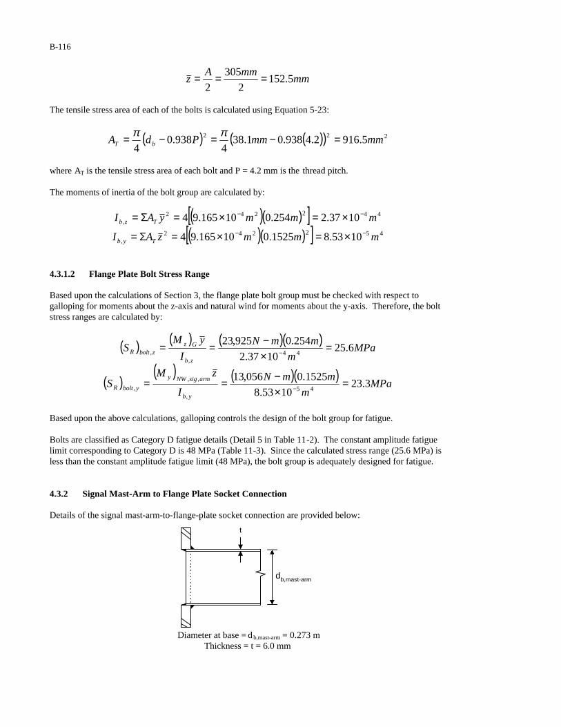
B-116
mmmmA
z 5.1522
305
2===
The tensile stress area of each of the bolts is calculated using Equation 5-23:
( ) ( )( ) 222 5.9162.4938.01.384
938.04
mmmmPdA bT =−=−= ππ
where AT is the tensile stress area of each bolt and P = 4.2 mm is the thread pitch.
The moments of inertia of the bolt group are calculated by:
( )( )[ ] 442242, 1037.2254.010165.94 mmmyAI Tzb
−− ×=×=Σ=
( )( )[ ] 452242, 1053.81525.010165.94 mmmzAI Tyb
−− ×=×=Σ=
4.3.1.2 Flange Plate Bolt Stress Range Based upon the calculations of Section 3, the flange plate bolt group must be checked with respect to galloping for moments about the z-axis and natural wind for moments about the y-axis. Therefore, the bolt stress ranges are calculated by:
( ) ( ) ( )( )MPa
m
mmN
I
yMS
zb
GzzboltR 6.25
1037.2
254.0925,2344
,, =
×−== −
( )( ) ( )( )
MPam
mmN
I
zMS
yb
armsigNWy
yboltR 3.231053.8
1525.0056,1345
,
,,
, =×−== −
Based upon the above calculations, galloping controls the design of the bolt group for fatigue. Bolts are classified as Category D fatigue details (Detail 5 in Table 11-2). The constant amplitude fatigue limit corresponding to Category D is 48 MPa (Table 11-3). Since the calculated stress range (25.6 MPa) is less than the constant amplitude fatigue limit (48 MPa), the bolt group is adequately designed for fatigue.
4.3.2 Signal Mast-Arm to Flange Plate Socket Connection Details of the signal mast-arm-to-flange-plate socket connection are provided below:
t
db,mast-arm
Diameter at base = d b,mast-arm = 0.273 m
Thickness = t = 6.0 mm
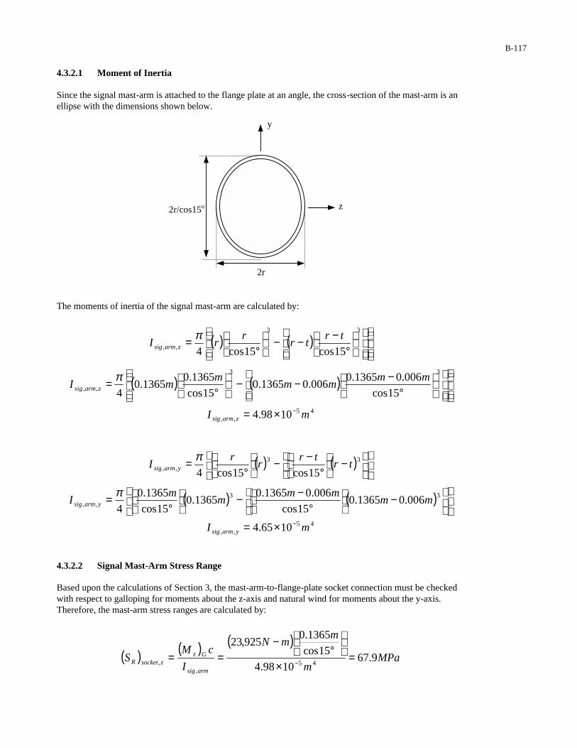
B-117
4.3.2.1 Moment of Inertia Since the signal mast-arm is attached to the flange plate at an angle, the cross-section of the mast-arm is an ellipse with the dimensions shown below. The moments of inertia of the signal mast-arm are calculated by:
( ) ( )
°−−−
°=
33
,, 15cos15cos4
trtr
rrI zarmsig
π
( ) ( )
°−−−
°=
33
,, 15cos
006.01365.0006.01365.0
15cos
1365.01365.0
4
mmmm
mmI zarmsig
π
45,, 1098.4 mI zarmsig
−×=
( ) ( )
−
°−−
°= 33
,, 15cos15cos4tr
trr
rI yarmsig
π
( ) ( )
−
°−−
°= 33
,, 006.01365.015cos
006.01365.01365.0
15cos
1365.0
4mm
mmm
mI yarmsig
π
45,, 1065.4 mI yarmsig
−×=
4.3.2.2 Signal Mast-Arm Stress Range Based upon the calculations of Section 3, the mast-arm-to-flange-plate socket connection must be checked with respect to galloping for moments about the z-axis and natural wind for moments about the y-axis. Therefore, the mast-arm stress ranges are calculated by:
( ) ( ) ( )MPa
m
mmN
I
cMS
armsig
GzzsocketR 9.67
1098.4
15cos
1365.0925,23
45,
, =×
°−
== −
y
z
2r
2r/cos15o

B-118
( ) ( ) ( )( )MPa
m
mmN
I
cMS
armsig
NWy
ysocketR 3.381065.4
1365.0056,1345
,, =
×−== −
The signal mast-arm-to-flange plate socket connection is classified as a Category E’ fatigue detail (Detail 16 in Table 11-2). The constant amplitude fatigue limit corresponding to Category E’ is 18 MPa (Table 11-3). Since the maximum calculated stress range (67.9 MPa) is greater than the constant amplitude fatigue limit (18 MPa), the socket connection is inadequately designed for fatigue. Potential Redesigns: 1. Assuming: (1) the fatigue resistance of the connection is not improved (i.e. a Category E’ socket
connection (Detail 16 in Table 11-2) is used) and (2) the thickness of the signal arm is not increased (i.e. t = 6.0 mm), the connection will be adequately designed for fatigue using a 0.522-m signal arm diameter.
2. Assuming: the fatigue resistance of the connection is not improved (i.e. a Category E’ socket
connection (Detail 16 in Table 11-2) is used), the connection will be adequately designed for fatigue using a signal arm with a 0.368-m diameter and 13-mm thickness.
3. Assuming: (1) the fatigue resistance of the connection is improved to Category E (i.e. a Category E
full-penetration connection (Detail 11 in Table 11-2) is used) and (2) the thickness of the signal arm is not increased (i.e. t = 6.0 mm), the connection will be adequately designed for fatigue using a 0.400-m signal arm diameter.
4. Assuming: (1) the fatigue resistance of the connection is improved to Category E (i.e. a Category E
full-penetration connection (Detail 11 in Table 11-2) is used) and (2) the diameter of the signal arm is not increased (i.e. db,mast-arm = 0.273 m), the connection will be adequately designed for fatigue using a signal arm thickness equal to 14.5 mm.
5. Assuming: the fatigue resistance of the connection is improved to Category E (i.e. a Category E full-
penetration connection (Detail 11 in Table 11-2) is used), the connection will be adequately designed for fatigue using a signal arm with a 0.333-m diameter and 9-mm thickness.
6. Assuming: the fatigue resistance of the connection is improved to Category C (i.e. the signal-arm-to-
flange-plate connection is fabricated with properly detailed stiffeners (Detail 21 in Table 11-2)), the connection will be adequately designed for fatigue without increasing either the signal arm diameter (i.e. d b,mast-arm = 0.273 m) or thickness (i.e. t = 6.0 mm).
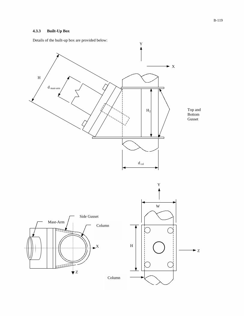
B-119
4.3.3 Built-Up Box Details of the built-up box are provided below:
Y
H
W
Column
Z
Column Mast-Arm
Side Gusset
X
Z
d col
d mast-arm
X
Y
H
H2 Top and Bottom Gusset

B-120
H = 686 mm Side gusset thickness = t SG = 8 mm W = 432 mm Top and bottom gusset thickness = tG = 9.5 mm H2 = 662.6 mm Diameter of column at mastarm = d col,mast = 548 mm
4.3.3.1 Moment of Inertia The moments of inertia of the built-up box are calculated by:
( ) ( )( ) ( )( )( ) 42323 00162.0338.0548.00095.0686.0008.012
12
12
1mmmmmmzAHtI SGboxz =
+=Σ+Σ=
( ) ( )( ) ( )( )( ) 42323, 00106.0270.0686.0008.0548.00095.0
12
12
12
1mmmmmmyAdtI mastcolGboxy =
+=Σ+Σ=
4.3.3.2 Built-Up Box Stress Range Based upon the calculations of Section 3, the built-up box must be checked with respect to galloping about the z-axis and natural wind about the y-axis. The stress range in the built-up box due to galloping is calculated by:
( ) ( )( )
( )( )MPa
m
mmN
I
cMS
boxz
GzboxR 1.5
00162.0
343.0925,234
=−==
The stress range in the built-up box due to natural wind gusts is calculated by:
( )( )
( )( )( )
MPam
mmN
I
cMS
boxy
armsigNWy
boxR 4.300106.0
274.0056,134
,, =−==
Based upon the above calculations, galloping controls the design of the built-up box for fatigue. The built-up-box-to-flange-plate connection is classified as a Category E’ fatigue detail (Detail 17 in Table 11-2). The constant amplitude fatigue limit corresponding to Category E’ is 18 MPa (Table 11-3). Since the calculated stress range (5.1 MPa) is less than the constant amplitude fatigue limit (18 MPa), the connection is adequately designed for fatigue. Since complete ring stiffeners are used to connect the built-up-box to the column, Detail 19 and Note b in Table 11-2 do not apply to this example. Instead, the new detail recommended in this report applies to this example. 4.4 Luminaire Mast-Arm-to-Column Connection The luminaire mast-arm-to-column connection (built-up box) is composed of three components that must be checked for fatigue: (1) flange-plate bolt group, (2) mast-arm-to-flange-plate socket connection, and (3) built-up box. Each of these components will be considered individually in the following sections.
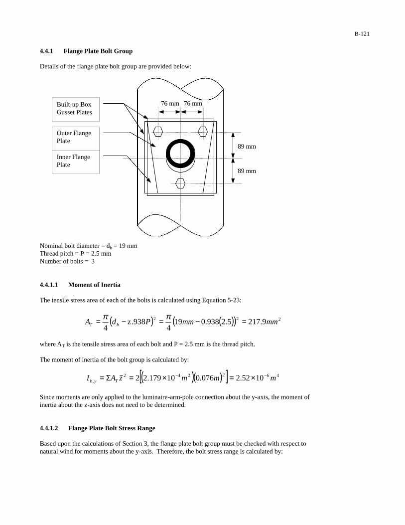
B-121
4.4.1 Flange Plate Bolt Group Details of the flange plate bolt group are provided below:
Nominal bolt diameter = db = 19 mm Thread pitch = P = 2.5 mm Number of bolts = 3
4.4.1.1 Moment of Inertia The tensile stress area of each of the bolts is calculated using Equation 5-23:
( ) ( )( ) 222 9.2175.2938.0194
938.z4
mmmmPdA bT =−=−= ππ
where AT is the tensile stress area of each bolt and P = 2.5 mm is the thread pitch. The moment of inertia of the bolt group is calculated by:
( )( )[ ] 462242, 1052.2076.010179.22 mmmzAI Tyb
−− ×=×=Σ=
Since moments are only applied to the luminaire-arm-pole connection about the y-axis, the moment of inertia about the z-axis does not need to be determined.
4.4.1.2 Flange Plate Bolt Stress Range Based upon the calculations of Section 3, the flange plate bolt group must be checked with respect tonatural wind for moments about the y-axis. Therefore, the bolt stress range is calculated by:
89 mm
89 mm
76 mm 76 mm Built-up Box Gusset Plates
Outer Flange Plate
Inner Flange Plate
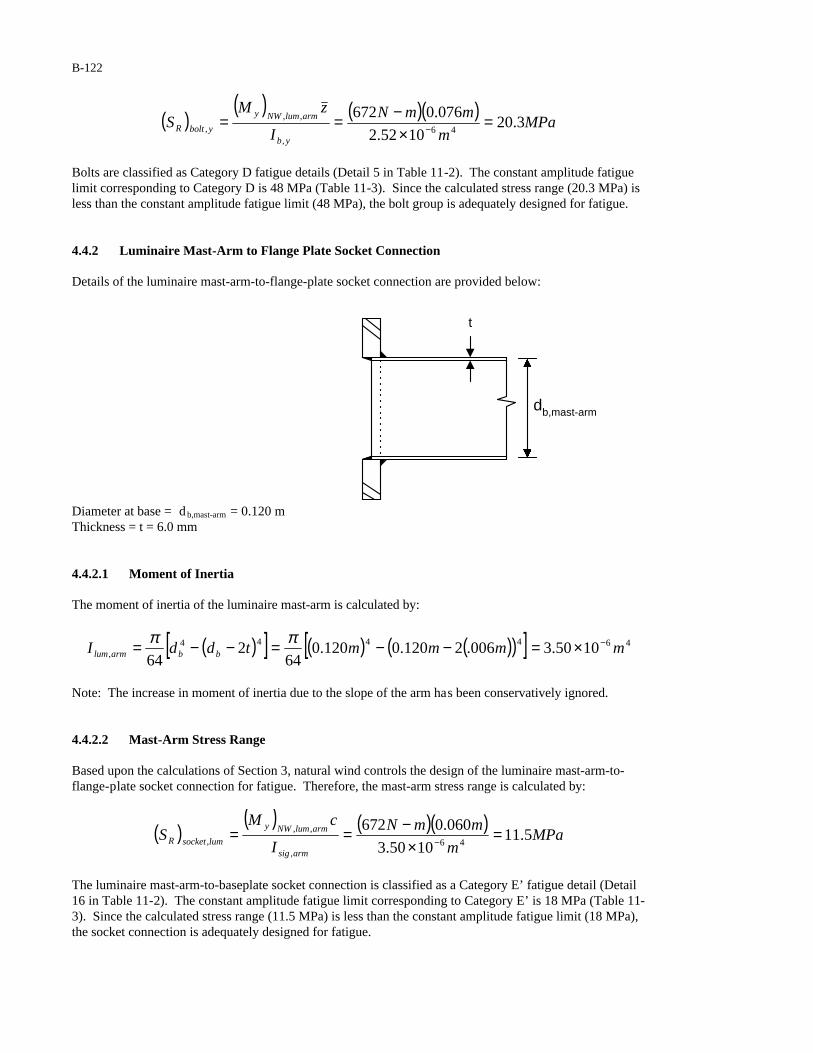
B-122
( )( ) ( )( )
MPam
mmN
I
zMS
yb
armlumNWy
yboltR 3.201052.2
076.067246
,
,,, =
×−== −
Bolts are classified as Category D fatigue details (Detail 5 in Table 11-2). The constant amplitude fatigue limit corresponding to Category D is 48 MPa (Table 11-3). Since the calculated stress range (20.3 MPa) is less than the constant amplitude fatigue limit (48 MPa), the bolt group is adequately designed for fatigue.
4.4.2 Luminaire Mast-Arm to Flange Plate Socket Connection
Details of the luminaire mast-arm-to-flange-plate socket connection are provided below:
t
db,mast-arm
Diameter at base = d b,mast-arm = 0.120 m Thickness = t = 6.0 mm 4.4.2.1 Moment of Inertia The moment of inertia of the luminaire mast-arm is calculated by:
( )[ ] ( ) ( )( )[ ] 464444, 1050.3006.2120.0120.0
642
64mmmmtddI bbarmlum
−×=−−=−−= ππ
Note: The increase in moment of inertia due to the slope of the arm has been conservatively ignored.
4.4.2.2 Mast-Arm Stress Range Based upon the calculations of Section 3, natural wind controls the design of the luminaire mast-arm-to-flange-plate socket connection for fatigue. Therefore, the mast-arm stress range is calculated by:
( )( ) ( )( )
MPam
mmN
I
cMS
armsig
armlumNWy
lumsocketR 5.111050.3
060.067246
,
,,, =
×−== −
The luminaire mast-arm-to-baseplate socket connection is classified as a Category E’ fatigue detail (Detail 16 in Table 11-2). The constant amplitude fatigue limit corresponding to Category E’ is 18 MPa (Table 11-3). Since the calculated stress range (11.5 MPa) is less than the constant amplitude fatigue limit (18 MPa), the socket connection is adequately designed for fatigue.
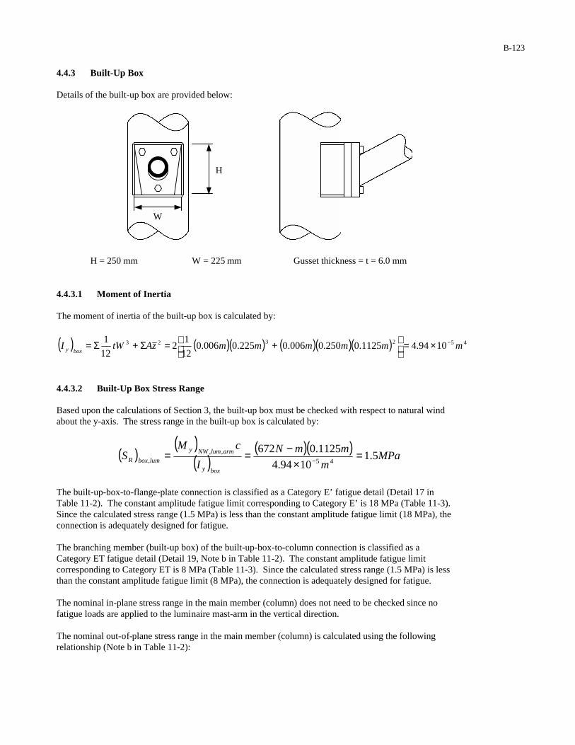
B-123
4.4.3 Built-Up Box Details of the built-up box are provided below:
H = 250 mm W = 225 mm Gusset thickness = t = 6.0 mm
4.4.3.1 Moment of Inertia
The moment of inertia of the built-up box is calculated by:
( ) ( )( ) ( )( )( ) 452323 1094.41125.0250.0006.0225.0006.012
12
12
1mmmmmmzAtWI
boxy−×=
+=Σ+Σ=
4.4.3.2 Built-Up Box Stress Range Based upon the calculations of Section 3, the built-up box must be checked with respect to natural wind about the y-axis. The stress range in the built-up box is calculated by:
( )( )
( )( )( )
MPam
mmN
I
cMS
boxy
armlumNWy
lumboxR 5.11094.4
1125.067245
,,, =
×−== −
The built-up-box-to-flange-plate connection is classified as a Category E’ fatigue detail (Detail 17 in Table 11-2). The constant amplitude fatigue limit corresponding to Category E’ is 18 MPa (Table 11-3). Since the calculated stress range (1.5 MPa) is less than the constant amplitude fatigue limit (18 MPa), the connection is adequately designed for fatigue. The branching member (built-up box) of the built-up-box-to-column connection is classified as a Category ET fatigue detail (Detail 19, Note b in Table 11-2). The constant amplitude fatigue limit corresponding to Category ET is 8 MPa (Table 11-3). Since the calculated stress range (1.5 MPa) is less than the constant amplitude fatigue limit (8 MPa), the connection is adequately designed for fatigue. The nominal in-plane stress range in the main member (column) does not need to be checked since no fatigue loads are applied to the luminaire mast-arm in the vertical direction. The nominal out-of-plane stress range in the main member (column) is calculated using the following relationship (Note b in Table 11-2):
W
H
B-124
( ) ( ) ( ) ( ) MPamm
mmMPa
t
tSS
c
bmemberbranchingRmembermainR 7.15.1
0.8
0.65.1 =
=
= α
where (SR)branching member is the calculated out-of-plane nominal stress range in the branching member induced by fatigue loads, t b is the wall thickness of the branching member (built-up box), tc is the wall thickness of the main member (column), and α is the out-of-plane bending ovalizing parameter for the main member. The main member (column) of the built-up-box-to-column connection is classified as a Category K2 fatigue detail (Detail 19, Note b in Table 11-2). The constant amplitude fatigue limit corresponding to Category K2
is 7 MPa (Table 11-3). However, the r/t ratio of the column at the location of the mast-arm is greater than 24. Therefore, the fatigue resistance has to be reduced in accordance with the following relationship (Note b from Table 11-2):
( ) ( ) ( ) ( ) MPa
mmmm
MPa
tr
FF Knn 7.5
0.82/8.510
247
247.07.0
2 =
×=
×∆=
where ( ) 2KnF∆ is the CAFL for fatigue Category K 2.
Since the calculated stress range (1.7 MPa) is less than the constant amplitude fatigue limit (5.7 MPa), the connection is adequately designed for fatigue. Since no fatigue loads inducing in-plane moments are applied to the luminaire arm, it is not necessary to check the main member (column) for a Category E fatigue detail at the bottom of the welded connection of the branching member (built-up box) (Detail 19, Note b in Table 11-2).
5 DEFLECTION Section 11.8 limits the vertical-plane mast-arm displacement to 0.2 meters under application of the limit state fatigue design load. Based upon the calculations of Section 3, galloping controls the design of the structure with respect to the deflection limit state. 5.1 Vertical-Plane Displacement Range of the Structure 5.1.1 Assumptions (1) The displacement range at the tip of the mast-arm is calculated using the superposition of the following
displacement components:
∆1: Displacement range at the tip of the mast-arm due to the deflection of the mast-arm (assuming a
cantilever beam fixed at the base of the mast-arm) under application of 1,signGF = 1100 N to sign 1.
∆2: Displacement range at the tip of the mast-arm due to the deflection of the mast-arm (assuming a
cantilever beam fixed at the base of the mast-arm) under application of 2,signGF = 700 N to sign 2.
∆3: Displacement range at the tip of the mast-arm due to the deflection of the mast-arm (assuming a
cantilever beam fixed at the base of the mast-arm) under application of 2,signalGF = 850 N to signal 2.

B-125
∆4: Displacement range at the tip of the mast-arm due to the deflection of the mast-arm (assuming a
cantilever beam fixed at the base of the mast-arm) under application of 3,signGF = 500 N to sign 3.
∆5: Displacement range at the tip of the mast-arm due to the deflection of the mast-arm (assuming a
cantilever beam fixed at the base of the mast-arm) under application of 3,signalGF = 1200 N to signal 3.
∆6: Displacement range at the tip of the mast-arm due to the rotation of the column (assuming a cantilever beam fixed at the base of the column) under application of the moment
GzM )( = 23,925 N-m.
(2) Calculation of each of the displacement quantities noted above is based upon the average moment of
inertia of each of the components. 5.1.2 Average Moment of Inertia of Column From previous calculations, the moment of inertia at the base of the column is:
44, 1086.6 mI basecol
−×=
The moment of inertia of the column at the mast-arm connection is:
( )[ ] ( ) ( )[ ] 44444,
4,, 1095.4016.0548.0548.0
642
64mmmmtddI mastcolmastcolmastcol
−×=−−=−−= ππ
The average moment of inertia of the column is:
444444
,,, 1091.5
2
1095.41086.6
2m
mmIII mastcolbasecol
avgcol−
−−
×=×+×=+
=
5.1.3 Average Moment of Inertia of Signal Mast-Arm The moment of inertia at the base of the signal mast-arm is:
( )[ ] ( ) ( )[ ] 454444,, 1049.4012.0273.0273.0
642
64mmmmtddI ttbasearmsig
−×=−−=−−= ππ
The moment of inertia at the tip of the signal mast-arm is:
( )[ ] ( ) ( )[ ] 454444,, 1012.1012.0174.0174.0
642
64mmmmtddI ttmastarmsig
−×=−−=−−= ππ
The average moment of inertia of the mastarm is:
454545
,,,,,, 1081.2
2
1012.11049.4
2m
mmIII mastarmsigbasearmsig
avgarmsig−
−−
×=×+×=+
=
Note: Increases in the moments of inertia above due to the angling of the mast-arm near the column have been conservatively ignored.

B-126
5.1.4 Mast-Arm Displacement Range 1∆
The displacement range at the tip of the mast-arm due to the galloping load applied to sign 1 is calculated by:
( ) ( )[ ] ( )( )( )( ) ( )[ ] mmm
mGPa
mNxx
EI
xF
avgarmsig
signG0002.045.01.93
1081.22006
45.011003
6 45
2
15,,
211
1 =−×
=−=∆ −
5.1.5 Mast-Arm Displacement Range 2∆
The displacement range at the tip of the mast-arm due to the galloping load applied to sign 2 is calculated by:
( ) ( )[ ] ( )( )( )( ) ( )[ ] mmm
mGPa
mNxx
EI
xF
avgarmsig
signG012.00.51.93
1081.22006
0.57003
6 45
2
25,,
222
2 =−×
=−=∆ −
5.1.6 Mast-Arm Displacement Range 3∆
The displacement range at the tip of the mast-arm due to the galloping load applied to signal 2 is calculated by:
( ) ( )[ ] ( )( )( )( ) ( )[ ] mmm
mGPa
mNxx
EI
xF
avgarmsig
signalG017.06.51.93
1081.22006
6.58503
6 45
2
35,,
232
3 =−×
=−=∆ −
5.1.7 Mast-Arm Displacement Range 4∆
The displacement range at the tip of the mast-arm due to the galloping load applied to sign 3 is calculated by:
( ) ( )[ ] ( )( )( )( ) ( )[ ] mmm
mGPa
mNxx
EI
xF
avgarmsig
signG020.05.81.93
1081.22006
5.85003
6 45
2
45,,
243
4 =−×
=−=∆ −
5.1.8 Mast-Arm Displacement Range 5∆
The displacement range at the tip of the mast-arm due to the galloping load applied to signal 3 is calculated by:
( ) ( )[ ] ( )( )( )( ) ( )[ ] mmm
mGPa
mNxx
EI
xF
avgarmsig
signalG054.01.91.93
1081.22006
1.912003
6 45
2
55,,
253
5 =−×
=−=∆ −
B-127
5.1.9 Mast-Arm Displacement Range ∆ 6
The rotation of the column at the location of the mast-arm is calculated by :
( ) ( )( )( )( ) rad
mGPa
mmN
EI
LM
avgcol
Gzcol 00108.0
1091.5200
35.5925,2344
,
2 =×
−== −θ
The displacement range at the tip of the mast-arm due to the rotation of the column is calculated by:
( )( ) mmradxcol 010.01.900108.05z ===∆ θ
5.1.10 Total Signal Mast-Arm Deflection Range total∆
The total displacement range at the tip of the signal mast-arm is obtained by the superposition of each of the deflection quantities:
654321 ∆+∆+∆+∆+∆+∆=∆ total
mmmmmmtotal 010.0054.0020.0017.0012.00002.0 +++++=∆
mtotal 113.0=∆
The allowable vertical-plane mast-arm displacement from Section 11.8 is 0.2 m. The computed deflection range at the tip of the mast-arm (0.113 m) does not exceed the allowable deflection range (0.2m). Therefore, the structure is adequately designed with respect to the deflection limit state.
C-1
APPENDIX C
GUIDANCE ON INSTALLATION, INSPECTION, MAINTENANCE,AND REPAIR OF STRUCTURAL SUPPORTS FOR HIGHWAY SIGNS,LUMINAIRES, AND TRAFFIC SIGNALS
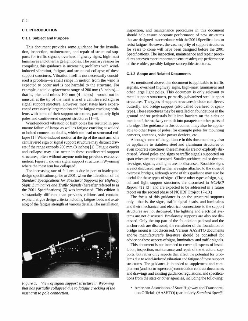
C.1 INTRODUCTION
C.1.1 Subject and Purpose
This document provides some guidance for the installa-tion, inspection, maintenance, and repair of structural sup-ports for traffic signals, overhead highway signs, high-mastluminaires and other large light poles. The primary reason forcompiling this guidance is increasing problems with wind-induced vibration, fatigue, and structural collapse of thesesupport structures. Vibration itself is not necessarily consid-ered a problem—a small range in motion from the wind isexpected to occur and is not harmful to the structure. Forexample, a total displacement range of 200 mm (8 inches)—that is, plus and minus 100 mm (4 inches)—would not beunusual at the tip of the mast arm of a cantilevered sign orsignal support structure. However, most states have experi-enced excessively large motion and/or fatigue cracking prob-lems with some of their support structures, particularly lightpoles and cantilevered support structures [1–4].
Wind-induced vibration of light poles has resulted in pre-mature failure of lamps as well as fatigue cracking at weldedor bolted connection details, which can lead to structural col-lapse [1]. Wind-induced motion at the tip of the mast arm of acantilevered sign or signal support structure may distract driv-ers if the range exceeds 200 mm (8 inches) [1]. Fatigue cracksand collapse may also occur in these cantilevered supportstructures, often without anyone noticing previous excessivemotion. Figure 1 shows a signal support structure in Wyomingwhere the mast arm has collapsed.
The increasing rate of failures is due in part to inadequatedesign specifications prior to 2001, when the 4th edition of theStandard Specifications for Structural Supports for HighwaySigns, Luminaires and Traffic Signals (hereafter referred to asthe 2001 Specifications) [5] was introduced. This edition issubstantially different than previous editions and containsexplicit fatigue design criteria including fatigue loads and a cat-alog of the fatigue strength of various details. The installation,
C-2
inspection, and maintenance procedures in this documentshould help ensure adequate performance of new structuresthat are designed in accordance with the 2001 Specifications toresist fatigue. However, the vast majority of support structuresfor years to come will have been designed before the 2001Specifications. The inspection, maintenance and repair proce-dures are even more important to ensure adequate performanceof these older, possibly fatigue-susceptible structures.
C.1.2 Scope and Related Documents
As mentioned above, this document is applicable to trafficsignals, overhead highway signs, high-mast luminaires andother large light poles. This document is only relevant tometal support structures, primarily galvanized steel supportstructures. The types of support structures include cantilever,butterfly, and bridge support (also called overhead or span-type). These structures may be installed on foundations in theground and/or pedestals built into barriers on the sides ormedian of the roadway or built into parapets or other parts ofa bridge. The guidance in this document may also be applic-able to other types of poles, for example poles for mountingcameras, antennas, solar power devices, etc.
Although some of the guidance in this document may alsobe applicable to stainless steel and aluminum structures oreven concrete structures, these materials are not explicitly dis-cussed. Wood poles and signs or traffic signals supported onspan wires are not discussed. Smaller architectural or decora-tive signs, signals, and lights are not discussed. Roadside signsare not discussed, and neither are signs attached to the sides ofoverpass bridges, although some of this guidance may also beuseful for these types of signs. (These other types of sign, sig-nal and light support structures are discussed in NCHRPReport 411 [3], and are expected to be addressed in a futurereport on the second phase of NCHRP Project 17-10.)
The focus of this guidance is on the structural supportsonly—that is, the signs, traffic signal heads, and luminairesand their mechanical and electrical connections to the supportstructures are not discussed. The lighting and electrical sys-tems are not discussed. Breakaway supports are also not dis-cussed. Only the top part of the foundation pedestal and theanchor rods are discussed; the remainder of the foundation orbridge mount is not discussed. Various AASHTO documentsand/or manufacturer’s literature should be consulted foradvice on these aspects of signs, luminaires, and traffic signals.
This document is not intended to cover all aspects of instal-lation, inspection, maintenance, and repair of the structural sup-ports, but rather only aspects that affect the potential for prob-lems due to wind-induced vibration and fatigue of these supportstructures. The guidance is intended to supplement and com-plement (and not to supercede) construction contract documentsand drawings and existing guidance, regulations, and specifica-tions from the state or other agencies, including the following:
• American Association of State Highway and Transporta-tion Officials (AASHTO) (particularly Standard Specifi-
Figure 1. View of signal support structure in Wyomingthat has partially collapsed due to fatigue cracking of themast arm to pole connection.
cations for Structural Supports for Highway Signs, Lumi-naires and Traffic Signals, 4th Edition, 2001 [5])
• Federal Highway Administration (FHWA) (particularlyBridge Inspector’s Training Manual [6])
• American Welding Society (AWS), (particularly AWSD1.1, Structural Welding Code—Steel [7]) (The BridgeWelding Code, AWS D1.5. is too restrictive to apply tothese structures)
• American Institute of Steel Construction (AISC) (partic-ularly Code of Standard Practice for Steel Buildingsand Bridges [8])
• Research Council For Structural Connections (RCSC)(particularly Specification for Structural Joints UsingASTM A325 or A490 Bolts [9])
• Occupational Safety and Health Administration (OSHA)(particularly 29 CFR Part 1926, Safety Standards for SteelErection [10])
Limited technical information is presented in this document(i.e. only information necessary to diagnose these problems inthe field and to appreciate why the additional quality controlprovisions are needed). For more detailed technical informa-tion, the reader is referred to NCHRP Report 412: Fatigue-Resistant Design of Cantilevered Signal, Sign, and Light Sup-ports. NCHRP Report 412 presents the findings from the firstphase of NCHRP Project 10-38. (This document was preparedas part of the second phase of Project 10-38 [2].) As mentionedpreviously, NCHRP Report 411 [3] (and an anticipated reporton the second phase of Project 17-10) covers a much greatervariety of signs, signals, and light supports made from a vari-ety of materials, and includes discussion of load cases anddesign for factors other than vibration and fatigue.
C.1.3 Short Course
This document may be read by itself or it may be used inconjunction with a PowerPoint presentation to form the basisof a one-day short course on the installation, inspection, main-tenance, and repair of these structural supports. This courseshould be developed and led by a local expert, either a statedepartment of transportation employee or a local consultant.
The guidance in this document and the training course areintended for structural engineers, materials engineers, traf-
C-3
fic engineers, field inspectors, construction inspectors, con-struction supervisors, and other technical personnel involvedin installation, inspection, maintenance, and repair of thesesupport structures. The reader should be familiar with basicaspects of fabrication, welding, bolting, corrosion and galva-nizing, construction, fabrication and construction inspection,structural behavior (load paths, stress, vibration, and fatigue),and in-service inspection of structures. A quick refreshercourse could be given on these topics the day before the shortcourse, if necessary.
Each participant in the short course should read this docu-ment before the short course. It is also assumed that thereader of this document and/or the participant in the shortcourse has a copy of and has reviewed the following:
• Bridge Inspector’s Training Manual, FHWA ReportNo. FHWA-PD-91-015, May 1995 [6]
• Standard Specifications for Structural Supports for High-way Signs, Luminaires and Traffic Signals, 4th Edition,2001 [5]
Other materials that will enhance the training are videos ofstructures vibrating excessively in the field, slides of typicaldetails and typical problems, drawings of standard structures,a Skidmore Wilhelm device for tightening bolts, and a fewsamples of small lengths of anchor rods (300 to 600 mmlong), A325 structural bolts, U-bolts, and other hardware.Parts of structures with actual fatigue cracks would also bevery useful. These parts of structures should be large enoughto contain the whole connection and can be cut out fromstructures that have failed in service or during fatigue testing.These additional materials should be provided by the state orother local agency so that they are pertinent to local climate,types of structures, foundations, structural details, usage ofweathering steel or paint, etc.
Table 1 shows a typical agenda for such a training course.The rotation capacity tests should be demonstrated for struc-tural bolts and anchor rods. This test is described in the Spec-ification for Structural Joints Using ASTM A325 or A490Bolts published in 1999 by the Research Council on Struc-tural Connections (RCSC) [9]. If fatigue cracked parts of struc-tures are available, locally used non-destructive evaluation(NDE) can be demonstrated, including dye-penetrant testing,magnetic particle testing, or even ultrasonic testing.
Time Subjects9-10 a.m. Introduction, motivation, types of structures, nomenclature (go over
drawings), materials (corrosion, fatigue and fracture), fabrication, and weld inspection and acceptance criteria
10-11 a.m. Vibration and fatigue problems, various wind-loading phenomena (videos), design, and mitigation devices
11 a.m.-noon. Installation and construction inspection 1-2 p.m. Installation of high-strength bolts and anchor rods (rotation capacity
test demonstrations) 2-3 p.m. In-service inspection, visual and NDE (NDE demonstrations) 3-4 p.m. Repair of construction defects, periodic maintenance, and in-service
repair
TABLE 1 Typical agenda for 1-day short course
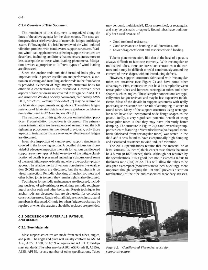
C.1.4 Overview of This Document
The remainder of this document is organized along thelines of the above agenda for the short course. The next sec-tion provides a brief overview of materials, fatigue and designissues. Following this is a brief overview of the wind-inducedvibration problem with cantilevered support structures. Vari-ous wind-loading phenomena affecting support structures aredescribed, including conditions that make structures more orless susceptible to these wind-loading phenomena. Mitiga-tion devices appropriate to different types of wind-loadingare discussed.
Since the anchor rods and field-installed bolts play animportant role in proper installation and performance, a sec-tion on selecting and installing anchor rods in the foundationis provided. Selection of high-strength structural bolts forother field connections is also discussed. However, otheraspects of fabrication are not covered in this guide. AASHTOand American Welding Society documents, particularly AWSD1.1, Structural Welding Code–Steel [7] may be referred tofor fabrication requirements and guidance. The relative fatigueresistance of fabricated details and some guidance on fabrica-tion is discussed in NCHRP Report 412 [1].
The next section of this guide focuses on installation prac-tices. Pre-installation inspection is discussed. The primaryissues in installation are the sequence of assembly and the bolttightening procedures. As mentioned previously, only thoseaspects of installation that are relevant to vibration and fatigueare discussed.
In-service inspection of cantilevered support structures iscovered in the following section. A detailed discussion is pro-vided of adequate inspection intervals for various cantileveredsupport structure types. A brief overview of the fatigue classi-fication of details is presented, including a discussion of someof the most fatigue prone details and where the cracks typicallyappear. The relative merits of various non-destructive evalua-tion (NDE) methods are discussed, but the emphasis is onvisual inspection. Periodic checking of anchor rod nuts andother bolted joints to see if they remain tight is also discussed.
Techniques for periodic maintenance are discussed, includ-ing touch-up of galvanizing or repainting, periodic retighten-ing of anchor rods and other bolts, etc. Repair techniques foranchor rods are discussed that are also useful for correctingconstruction errors. Repair of small fatigue cracks in structuralmembers is discussed. Criteria for when fatigue cracks may berepaired or when the structure should be replaced are provided.
C.2 DISCUSSION OF MATERIALS, FATIGUE,AND DESIGN
C.2.1 Steel Materials
Most support structures are made from steel tubes, angles,and plate. The angle and plate will usually conform to ASTMA36, A572, A588, or A709 or equivalent AASHTO bridge-steel standards. The tubes may be A500, A53 Grade B, A595A,A135, API 5L, or any number of other specifications. Tubes
C-4
may be round, multisided (8, 12, or more sides), or rectangularand may be prismatic or tapered. Round tubes have tradition-ally been used because of
• Good torsional resistance,• Good resistance to bending in all directions, and• Lower drag coefficient and associated wind loading.
Tube to plate connection, like that at the base of a post, isalways difficult to fabricate correctly. With rectangular ormultisided tubes, there are stress concentrations at the cor-ners and it may be difficult to weld continuously around thecorners of these shapes without introducing defects.
However, support structures fabricated with rectangulartubes are attractive (see Figure 2) and have some otheradvantages. First, connections can be a lot simpler betweenrectangular tubes and between rectangular tubes and othershapes such as angles. These simpler connections are typi-cally more fatigue resistant and may be less expensive to fab-ricate. Most of the details in support structures with reallypoor fatigue resistance are a result of attempting to attach toround tubes. Many of the support structures using rectangu-lar tubes have also incorporated wide-flange shapes as theposts. Finally, a very significant potential benefit of usingrectangular tubes is that they may have inherently betterdamping. The structure in Figure 2 (a cantilevered sign sup-port structure featuring a Vierendeel truss (no diagonal mem-bers) fabricated from rectangular tubes) was tested in thefield and it was found to have exceptionally high dampingand associated resistance to wind-induced vibration.
The 2001 Specifications require that the material be atleast 3 mm (0.125 inches) thick, except truss chords that mustbe 4.8 mm (0.1875 inches) thick. Although not required bythe specifications, it is a good idea not to exceed a radius tothickness ratio (R/t) of 32. This will allow the tubes to bedesigned as compact (more resistant to local buckling). Moreimportant though, keeping the R/t small prevents distortion(ovalization) of the tube and associated secondary stresses.
Figure 2. Cantilevered Vierendeel truss sign support structure.

Distortion occurs when there is bending or when stiffeners,gussets, or branching members press or pull on the cross sec-tions. In many cases, tubes with R/t greater than 32 have hadsignificant fatigue problems caused by these distortions. Ide-ally, the R/t should be less than or equal to 24 to prevent thistype of distortion entirely.
C.2.2 Corrosion Protection
Structural members should be galvanized to protect thestructure from corrosion. Although there are some experi-ments to the contrary, the majority of test data show that gal-vanizing does not significantly decrease the fatigue resis-tance of details relative to non-galvanized steel. Galvanizingis effective at controlling corrosion but has some limitationson the life. Depending on climate, the galvanizing may onlylast 20 to 30 years. Many existing support structures are near-ing the end of the useful life of the galvanizing and are begin-ning to exhibit corrosion.
Other coatings may be used to prevent corrosion of steelstructures, but special consideration should be given to howthe coating may affect the performance of bolted joints andthe anchor rod connection.
Uncoated weathering steel has been used successfully inmany support structures, but the use of weathering steelrequires special consideration beyond the scope of this guide.Uncoated weathering steel has corroded severely in somesupport structures, particularly if there are telescoping jointsor lap joints, if vegetation is allowed to touch the structure,or if snow and deicing salt is plowed onto the structure.
Stainless steel and aluminum structures have been used fortheir corrosion resistance. Aluminum may also be specifiedfor its light weight and associated ease of erection. Stainlesssteel has approximately the same fatigue resistance as struc-tural steel. However, aluminum structural details are moresusceptible to fatigue than comparable steel details. This isbecause aluminum has approximately one-third the fatigueresistance of steel.
C.2.3 Expected Lifetime
Table 3-3 in the 2001 Specifications provides recommendedminimum design life for various support structures. Lumi-naires exceeding 15 m (49.2 ft) in height and overhead signstructures (cantilevers and bridge supports) should be designedfor 50 years. As noted above, the galvanizing may not last thatlong in some locations. Smaller luminaires and traffic signalsupports are designed for a minimum life of 25 years.
C.2.4 Design
Support structures are designed primarily to resist windloads. The size and thickness of the members of support struc-tures are usually determined so that they have adequate stiff-ness to limit deflection under dead load and adequate strengthto resist the once in a lifetime maximum loads, usually galeor hurricane force wind loads.
C-5
As discussed in the introduction, these support structuresmay not have been explicitly designed for vibration or fatiguein the past because there were no clear design requirements.In most cases, it wasn’t necessary to explicitly design forvibration or fatigue because the structure (designed only forstiffness and strength) did not experience vibration or fatigueproblems. However, the increasing incidence of vibration andfatigue problems with support structures, particularly lumi-naires and cantilevered sign and signal supports, indicates thatdesign for stiffness and strength alone is not sufficient.
In the 2001 Specifications, the fatigue design provisionsfor support structures are given in Section 11, includingfatigue design loads. Fatigue design loads are supposed torepresent loads that may occur for a few hours each year andare therefore much less than the strength design loads.
For structures designed in accordance with new 2001Specifications, the choice of connection details will usuallybe governed by the fatigue design provisions. The best detailfrom a fatigue design standpoint is often expensive and dif-ficult to fabricate. Sometimes even the size and thickness ofthe members will also be dictated by fatigue.
C.2.5 Fatigue
Fatigue resistance of particular details is determined by test-ing full-scale structural members under cyclic loads. The load-ing is characterized in terms of the nominal stress in the struc-tural member remote from the welds or bolts in the detail. Thenominal stress is conveniently obtained from standard designequations using member forces and moments. Testing hasindicated that the primary effect of constant amplitude loadingcan be accounted for in the live-load stress range (i.e., the dif-ference between the maximum and the minimum stress in aloading cycle). Thus, it is the fluctuation of the stress and notthe absolute value of the stress that affects fatigue. The con-stant dead load stress does not affect fatigue.
The strength and type of steel have a negligible effect onthe fatigue resistance expected for a particular detail. Thewelding process and minor deviations in weld quality fromAWS D1.1 standards, while important, also do not typicallyhave a significant effect on the fatigue resistance. The inde-pendence of the fatigue resistance from the type of steel andweld filler metal greatly simplifies the development of designrules for fatigue since it eliminates the need to generate datafor every type of steel.
Fatigue failure of a support structure basically occurs be-cause the stress ranges resulting from the wind or truck-induced gusts exceed the fatigue thresholds at critical details.Usually, these failures cannot be blamed on weld defects;rather, they are an indication that the structure is not ade-quately designed for the fluctuating loads and is experienc-ing excessively large stress ranges. This is a good reason tobelieve that other similar structures will soon be having sim-ilar cracking problems. Therefore, if a fatigue failure hasoccurred in a structure, one cannot be complacent aboutinspecting similar structures. All similar structures should beintensively inspected immediately.

It is a commonly held but incorrect assumption that cracksmay be caused by overloading the structure. In some cases,large variable message signs have been placed on a trussdesigned for flat green signs, and then fatigue problems haveoccurred. These problems are likely from the increased areaof the sign, which increases the gust load ranges and the asso-ciated stress ranges from wind and trucks, rather than fromthe increased dead load stress.
In the 2001 Specifications, the fatigue design provisionsfor support structures are given in Section 11. These fatiguedesign provisions are similar to those in the bridge specifica-tions. The fatigue design procedures are based on control ofthe nominal stress range and knowledge of the fatigue thresh-old of the details. Various details are shown in Figure 11-1.Each of these details is assigned a “Stress Category” in Table11-2. The fatigue threshold stress range for each category isgiven in Table 11-3. The support structures should be designedso that the stress ranges due to the fatigue design loads areless than the fatigue thresholds for each detail, thus ensuringthat fatigue will not occur even for a large number (hundredsof millions) of applied load cycles. Design calculations shouldbe prepared and stamped by a professional engineer explic-itly showing the fatigue design as well as the traditional allow-able stress design for strength.
Since the fatigue resistance of various grades of steel andanchor rods is the same, it typically is not cost-effective to usehigh-strength steel, higher than 420 MPa yield strength. If thedimensions of the members or anchor rods are decreased totake advantage of the high-strength steel for the maximumstrength design loads, the stress ranges under the fatiguedesign loads will increase and fatigue will become more of aproblem.
C.2.6 Notch Toughness
Since fatigue cracking is possible in these support struc-tures, it is important that the materials used for anchor rodsand main structural members have some minimum level ofnotch toughness (specified with the Charpy-V-notch test, orCVN) in order to avoid brittle fracture from small cracks.Materials that meet minimum CVN requirements are usuallyalso more weldable and less susceptible to weld defects.
Structural members and anchor rods should have CVN atleast comparable to the non-fracture-critical bridge require-ments—that is, the members and anchor rods should have atleast 20 Joules (15 ft-lb) at room temperature and weld fillershould be used which provides CVN of at least 27 Joules(20 ft-lb) at −18°C (0°F). Most present materials used forthese support structures are believed to have toughness evengreater than these levels of CVN would provide, even thoughit is not usually specified. Even though most of the grades ofsteel, filler metal, and anchor rods have adequate notch tough-ness, there is typically an inverse relationship between notchtoughness and strength such that the higher strength materialsusually have lower notch toughness. This is another good rea-son to use only lower-strength grades.
C-6
The 2001 Specifications requires that steel “members”thicker than 13 mm meet these bridge steel CVN require-ments. This is interpreted to not include anchor rods. It maybe expensive or not even possible to get some anchor rods ortubular products with a supplemental CVN requirement. Forexample, some tubular members will be too thin to get evena sub-size CVN specimen. Since most materials meet theCVN requirement without having to actually specify it or payfor it, supplemental CVN specifications are not recommendedfor steel members or anchor rods other than for membersthicker than 13 mm. Some exceptions may be when
• There is the possibility of seismic loading;• There are concerns about weldability of the steel mem-
bers or anchor rods; or• A53 Grade B pipe is used, which is not really intended
for structural use.
Usually, anchor rods should conform to ASTM F1554-97,Standard Specification for Anchor Bolts, Steel, 36, 55, and105-ksi Yield Strength [11], which is essentially the same asAASHTO M314-90, and these anchor rods have good frac-ture toughness. Alternatively, reinforcing bars conforming toASTM A706-96, Standard Specification for Low-Alloy SteelDeformed and Plain Bars for Concrete Reinforcement [12]may be threaded and used. Ordinary reinforcing bars con-forming to ASTM A615-96, Standard Specification forDeformed and Plain Billet-Steel Bars for Concrete Rein-forcement [13] should not be used for these support struc-tures because of possible low toughness.
Using materials with additional notch toughness (abovethese minimum levels) would not significantly decrease thetime to failure of the structure by fatigue. This is because cracksgrow at an exponential rate, and 95 percent of the life is con-sumed while the crack size is less than a few millimeters. Eventhough additional fracture toughness may correspond with agreater crack length at the time of failure, it does not corre-spond with a significantly longer time to failure.
This is also the reason why, unless there is a suspectedcrack or there have been cracks in similar details in similarstructures, it is usually not cost-effective to perform ultra-sonic testing or other non-destructive testing (other thanvisual) on anchor rods or other details. There is only a smallwindow in time when the cracks are both large enough todetect and small enough to not yet cause fracture.
It should be noted that at least one agency, MichiganDepartment of Transportation, feels that it is worthwhile toorder anchor rods with a supplemental CVN requirement andto perform ultrasonic testing of anchor rods and other details[14]. However, the situation in Michigan is special, sincethey had a series of fatigue failures in anchor rods on somesign support structures and were sued for a substantial amountas a result of a fatality. They feel that the small extension ofthe fatigue life provided by these measures is worth the addi-tional costs.
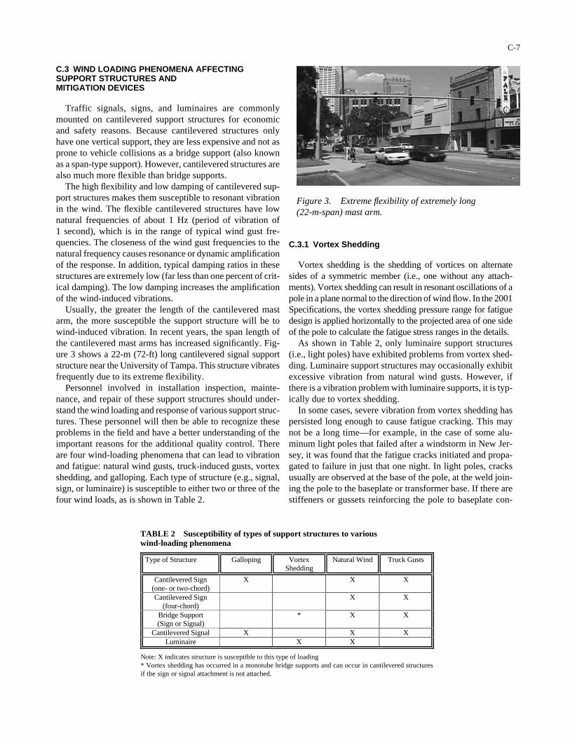
C.3 WIND LOADING PHENOMENA AFFECTINGSUPPORT STRUCTURES AND MITIGATION DEVICES
Traffic signals, signs, and luminaires are commonlymounted on cantilevered support structures for economicand safety reasons. Because cantilevered structures onlyhave one vertical support, they are less expensive and not asprone to vehicle collisions as a bridge support (also knownas a span-type support). However, cantilevered structures arealso much more flexible than bridge supports.
The high flexibility and low damping of cantilevered sup-port structures makes them susceptible to resonant vibrationin the wind. The flexible cantilevered structures have lownatural frequencies of about 1 Hz (period of vibration of 1 second), which is in the range of typical wind gust fre-quencies. The closeness of the wind gust frequencies to thenatural frequency causes resonance or dynamic amplificationof the response. In addition, typical damping ratios in thesestructures are extremely low (far less than one percent of crit-ical damping). The low damping increases the amplificationof the wind-induced vibrations.
Usually, the greater the length of the cantilevered mastarm, the more susceptible the support structure will be towind-induced vibration. In recent years, the span length ofthe cantilevered mast arms has increased significantly. Fig-ure 3 shows a 22-m (72-ft) long cantilevered signal supportstructure near the University of Tampa. This structure vibratesfrequently due to its extreme flexibility.
Personnel involved in installation inspection, mainte-nance, and repair of these support structures should under-stand the wind loading and response of various support struc-tures. These personnel will then be able to recognize theseproblems in the field and have a better understanding of theimportant reasons for the additional quality control. Thereare four wind-loading phenomena that can lead to vibrationand fatigue: natural wind gusts, truck-induced gusts, vortexshedding, and galloping. Each type of structure (e.g., signal,sign, or luminaire) is susceptible to either two or three of thefour wind loads, as is shown in Table 2.
C-7
C.3.1 Vortex Shedding
Vortex shedding is the shedding of vortices on alternatesides of a symmetric member (i.e., one without any attach-ments). Vortex shedding can result in resonant oscillations of apole in a plane normal to the direction of wind flow. In the 2001Specifications, the vortex shedding pressure range for fatiguedesign is applied horizontally to the projected area of one sideof the pole to calculate the fatigue stress ranges in the details.
As shown in Table 2, only luminaire support structures(i.e., light poles) have exhibited problems from vortex shed-ding. Luminaire support structures may occasionally exhibitexcessive vibration from natural wind gusts. However, ifthere is a vibration problem with luminaire supports, it is typ-ically due to vortex shedding.
In some cases, severe vibration from vortex shedding haspersisted long enough to cause fatigue cracking. This maynot be a long time—for example, in the case of some alu-minum light poles that failed after a windstorm in New Jer-sey, it was found that the fatigue cracks initiated and propa-gated to failure in just that one night. In light poles, cracksusually are observed at the base of the pole, at the weld join-ing the pole to the baseplate or transformer base. If there arestiffeners or gussets reinforcing the pole to baseplate con-
Type of Structure Galloping Vortex Shedding
Natural Wind Truck Gusts
Cantilevered Sign (one- or two-chord)
X X X
Cantilevered Sign (four-chord)
X X
Bridge Support (Sign or Signal)
* X X
Cantilevered Signal X X X Luminaire X X
Note: X indicates structure is susceptible to this type of loading * Vortex shedding has occurred in a monotube bridge supports and can occur in cantilevered structures if the sign or signal attachment is not attached.
Figure 3. Extreme flexibility of extremely long (22-m-span) mast arm.
TABLE 2 Susceptibility of types of support structures to various wind-loading phenomena
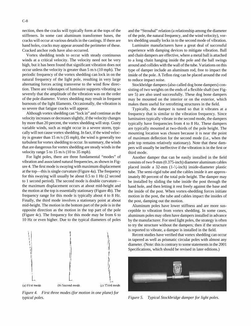
nection, then the cracks will typically form at the tops of thestiffeners. In some cast aluminum transformer bases, thecracks will occur at various details in the castings. If there arehand holes, cracks may appear around the perimeter of these.Cracked anchor rods have also occurred.
Vortex shedding tends to occur with steady continuouswinds at a critical velocity. The velocity need not be veryhigh, but it has been found that significant vibration does notoccur unless the velocity is greater than 5 m/s (10 mph). Theperiodic frequency of the vortex shedding can lock in on thenatural frequency of the light pole, resulting in very largealternating forces acting transverse to the wind flow direc-tion. There are videotapes of luminaire supports vibrating soseverely that the amplitude of the vibration was on the orderof the pole diameter. Vortex shedding may result in frequentburnouts of the light filaments. Occasionally, the vibration isso severe that fatigue cracks will appear.
Although vortex shedding can “lock in” and continue as thevelocity increases or decreases slightly, if the velocity changesby more than 20 percent, the vortex shedding will stop. Gustyvariable winds, such as might occur in a severe storm, typi-cally will not cause vortex shedding. In fact, if the wind veloc-ity is greater than 15 m/s (35 mph), the wind is generally tooturbulent for vortex shedding to occur. In summary, the windsthat are dangerous for vortex shedding are steady winds in thevelocity range 5 to 15 m/s (10 to 35 mph).
For light poles, there are three fundamental “modes” ofvibration and associated natural frequencies, as shown in Fig-ure 4. The first mode is swaying with maximum displacementat the top—this is single curvature (Figure 4a). The frequencyfor this swaying will usually be about 0.5 to 1 Hz (2 secondto 1 second period). The second mode is double curvature—the maximum displacement occurs at about mid-height andthe motion at the top is essentially stationary (Figure 4b). Thefrequency range for this mode is typically about 4 to 8 Hz.Finally, the third mode involves a stationary point at aboutmid-height. The motion in the bottom part of the pole is in theopposite direction as the motion in the top part of the pole(Figure 4c). The frequency for this mode may be from 6 to 10 Hz or even higher. Due to the typical diameters of poles
C-8
and the “Strouhal” relation (a relationship among the diameterof the pole, the natural frequency, and the wind velocity), vor-tex shedding usually locks in to the second mode of vibration.
Luminaire manufacturers have a great deal of successfulexperience with damping devices to mitigate vibration. Balland chain dampers are effective, where a metal ball is attachedto a long chain hanging inside the pole and the ball swingsaround and collides with the wall of the tube. Variations on thistype of damper include an aluminum rod, free to impact theinside of the pole. A Teflon ring can be placed around the rodto reduce impact noise.
Stockbridge dampers (also called dog bone dampers) con-sisting of two weights on the ends of a flexible shaft (see Fig-ure 5) are also used successfully. These dog bone dampersmay be mounted on the interior or on the exterior, whichmakes them useful for retrofitting structures in the field.
Typically, the damper is tuned so that it vibrates at afrequency that is similar to the vibration frequency. Sinceluminaires typically vibrate in the second mode, the damperstypically have frequencies from 4 to 8 Hz. These dampersare typically mounted at two-thirds of the pole height. Themounting location was chosen because it is near the pointof maximum deflection for the second mode (i.e., when thepole top remains relatively stationary). Note that these dam-pers will usually be ineffective if the vibration is in the first orthird mode.
Another damper that can be easily installed in the fieldconsists of two 9-mm (0.375-inch) diameter aluminum cablesplaced inside a 32-mm (1-1⁄4-inch) inside-diameter plastictube. The semi-rigid tube and the cables inside it are approx-imately 80 percent of the total pole height. The damper maybe installed by sliding the tube inside the post through thehand hole, and then letting it rest freely against the base andthe inside of the post. When vortex-shedding forces initiatemotion in the post, the tube and cables impact the insides ofthe post, damping out the motion.
Aluminum poles have lower stiffness and are more sus-ceptible to vibration from vortex shedding. In some cases,aluminum poles may often have dampers installed in advanceby the manufacturer. For steel light poles, the strategy is oftento try the structure without the dampers; then if the structureis reported to vibrate, a damper is installed in the field.
Recent studies have verified that vortex shedding can occurin tapered as well as prismatic circular poles with almost anydiameter. (Note: this is contrary to some statements in the 2001Specifications, which should be revised in later editions.)
Figure 5. Typical Stockbridge damper for light poles.Figure 4. First three modes (for motion in one plane) fortypical poles.
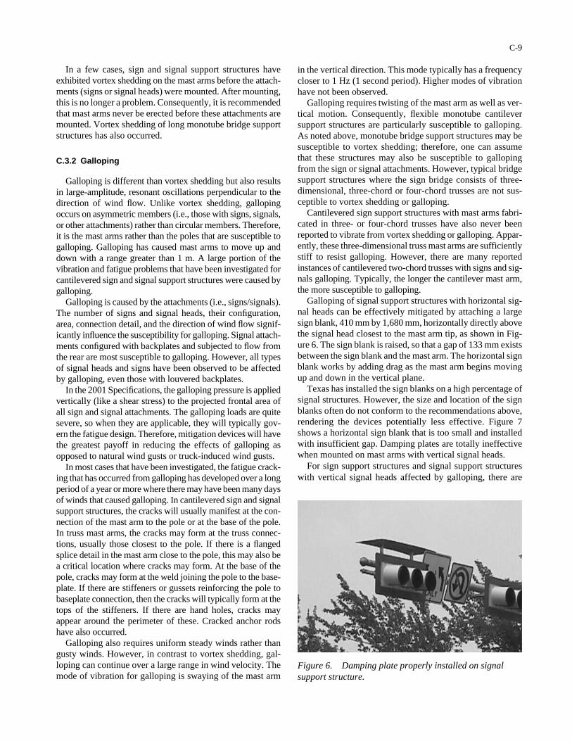
In a few cases, sign and signal support structures haveexhibited vortex shedding on the mast arms before the attach-ments (signs or signal heads) were mounted. After mounting,this is no longer a problem. Consequently, it is recommendedthat mast arms never be erected before these attachments aremounted. Vortex shedding of long monotube bridge supportstructures has also occurred.
C.3.2 Galloping
Galloping is different than vortex shedding but also resultsin large-amplitude, resonant oscillations perpendicular to thedirection of wind flow. Unlike vortex shedding, gallopingoccurs on asymmetric members (i.e., those with signs, signals,or other attachments) rather than circular members. Therefore,it is the mast arms rather than the poles that are susceptible togalloping. Galloping has caused mast arms to move up anddown with a range greater than 1 m. A large portion of thevibration and fatigue problems that have been investigated forcantilevered sign and signal support structures were caused bygalloping.
Galloping is caused by the attachments (i.e., signs/signals).The number of signs and signal heads, their configuration,area, connection detail, and the direction of wind flow signif-icantly influence the susceptibility for galloping. Signal attach-ments configured with backplates and subjected to flow fromthe rear are most susceptible to galloping. However, all typesof signal heads and signs have been observed to be affectedby galloping, even those with louvered backplates.
In the 2001 Specifications, the galloping pressure is appliedvertically (like a shear stress) to the projected frontal area ofall sign and signal attachments. The galloping loads are quitesevere, so when they are applicable, they will typically gov-ern the fatigue design. Therefore, mitigation devices will havethe greatest payoff in reducing the effects of galloping asopposed to natural wind gusts or truck-induced wind gusts.
In most cases that have been investigated, the fatigue crack-ing that has occurred from galloping has developed over a longperiod of a year or more where there may have been many daysof winds that caused galloping. In cantilevered sign and signalsupport structures, the cracks will usually manifest at the con-nection of the mast arm to the pole or at the base of the pole.In truss mast arms, the cracks may form at the truss connec-tions, usually those closest to the pole. If there is a flangedsplice detail in the mast arm close to the pole, this may also bea critical location where cracks may form. At the base of thepole, cracks may form at the weld joining the pole to the base-plate. If there are stiffeners or gussets reinforcing the pole tobaseplate connection, then the cracks will typically form at thetops of the stiffeners. If there are hand holes, cracks mayappear around the perimeter of these. Cracked anchor rodshave also occurred.
Galloping also requires uniform steady winds rather thangusty winds. However, in contrast to vortex shedding, gal-loping can continue over a large range in wind velocity. Themode of vibration for galloping is swaying of the mast arm
C-9
Figure 6. Damping plate properly installed on signalsupport structure.
in the vertical direction. This mode typically has a frequencycloser to 1 Hz (1 second period). Higher modes of vibrationhave not been observed.
Galloping requires twisting of the mast arm as well as ver-tical motion. Consequently, flexible monotube cantileversupport structures are particularly susceptible to galloping.As noted above, monotube bridge support structures may besusceptible to vortex shedding; therefore, one can assumethat these structures may also be susceptible to gallopingfrom the sign or signal attachments. However, typical bridgesupport structures where the sign bridge consists of three-dimensional, three-chord or four-chord trusses are not sus-ceptible to vortex shedding or galloping.
Cantilevered sign support structures with mast arms fabri-cated in three- or four-chord trusses have also never beenreported to vibrate from vortex shedding or galloping. Appar-ently, these three-dimensional truss mast arms are sufficientlystiff to resist galloping. However, there are many reportedinstances of cantilevered two-chord trusses with signs and sig-nals galloping. Typically, the longer the cantilever mast arm,the more susceptible to galloping.
Galloping of signal support structures with horizontal sig-nal heads can be effectively mitigated by attaching a largesign blank, 410 mm by 1,680 mm, horizontally directly abovethe signal head closest to the mast arm tip, as shown in Fig-ure 6. The sign blank is raised, so that a gap of 133 mm existsbetween the sign blank and the mast arm. The horizontal signblank works by adding drag as the mast arm begins movingup and down in the vertical plane.
Texas has installed the sign blanks on a high percentage ofsignal structures. However, the size and location of the signblanks often do not conform to the recommendations above,rendering the devices potentially less effective. Figure 7shows a horizontal sign blank that is too small and installedwith insufficient gap. Damping plates are totally ineffectivewhen mounted on mast arms with vertical signal heads.
For sign support structures and signal support structureswith vertical signal heads affected by galloping, there are
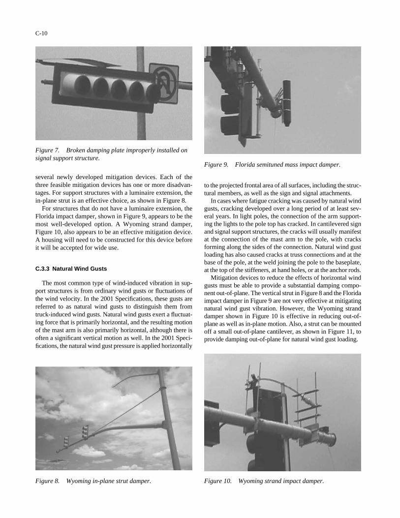
several newly developed mitigation devices. Each of thethree feasible mitigation devices has one or more disadvan-tages. For support structures with a luminaire extension, thein-plane strut is an effective choice, as shown in Figure 8.
For structures that do not have a luminaire extension, theFlorida impact damper, shown in Figure 9, appears to be themost well-developed option. A Wyoming strand damper,Figure 10, also appears to be an effective mitigation device.A housing will need to be constructed for this device beforeit will be accepted for wide use.
C.3.3 Natural Wind Gusts
The most common type of wind-induced vibration in sup-port structures is from ordinary wind gusts or fluctuations ofthe wind velocity. In the 2001 Specifications, these gusts arereferred to as natural wind gusts to distinguish them fromtruck-induced wind gusts. Natural wind gusts exert a fluctuat-ing force that is primarily horizontal, and the resulting motionof the mast arm is also primarily horizontal, although there isoften a significant vertical motion as well. In the 2001 Speci-fications, the natural wind gust pressure is applied horizontally
C-10
to the projected frontal area of all surfaces, including the struc-tural members, as well as the sign and signal attachments.
In cases where fatigue cracking was caused by natural windgusts, cracking developed over a long period of at least sev-eral years. In light poles, the connection of the arm support-ing the lights to the pole top has cracked. In cantilevered signand signal support structures, the cracks will usually manifestat the connection of the mast arm to the pole, with cracksforming along the sides of the connection. Natural wind gustloading has also caused cracks at truss connections and at thebase of the pole, at the weld joining the pole to the baseplate,at the top of the stiffeners, at hand holes, or at the anchor rods.
Mitigation devices to reduce the effects of horizontal windgusts must be able to provide a substantial damping compo-nent out-of-plane. The vertical strut in Figure 8 and the Floridaimpact damper in Figure 9 are not very effective at mitigatingnatural wind gust vibration. However, the Wyoming stranddamper shown in Figure 10 is effective in reducing out-of-plane as well as in-plane motion. Also, a strut can be mountedoff a small out-of-plane cantilever, as shown in Figure 11, toprovide damping out-of-plane for natural wind gust loading.
Figure 10. Wyoming strand impact damper.
Figure 9. Florida semituned mass impact damper.
Figure 7. Broken damping plate improperly installed onsignal support structure.
Figure 8. Wyoming in-plane strut damper.
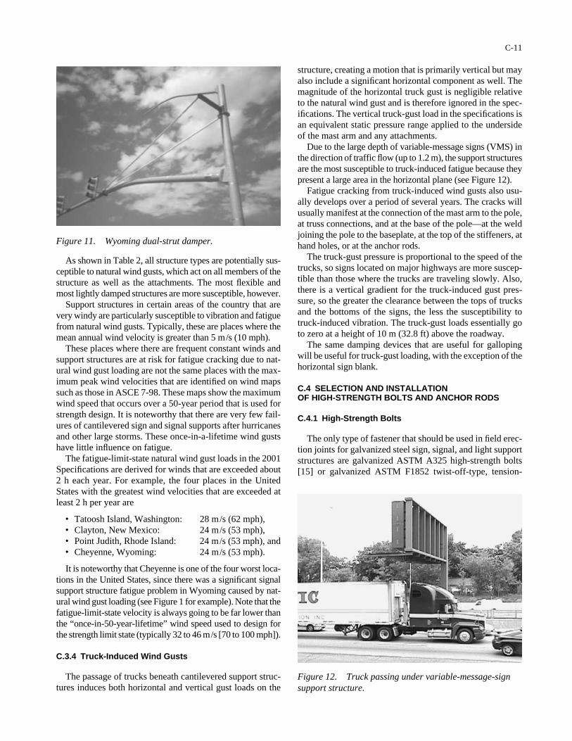
As shown in Table 2, all structure types are potentially sus-ceptible to natural wind gusts, which act on all members of thestructure as well as the attachments. The most flexible andmost lightly damped structures are more susceptible, however.
Support structures in certain areas of the country that arevery windy are particularly susceptible to vibration and fatiguefrom natural wind gusts. Typically, these are places where themean annual wind velocity is greater than 5 m/s (10 mph).
These places where there are frequent constant winds andsupport structures are at risk for fatigue cracking due to nat-ural wind gust loading are not the same places with the max-imum peak wind velocities that are identified on wind mapssuch as those in ASCE 7-98. These maps show the maximumwind speed that occurs over a 50-year period that is used forstrength design. It is noteworthy that there are very few fail-ures of cantilevered sign and signal supports after hurricanesand other large storms. These once-in-a-lifetime wind gustshave little influence on fatigue.
The fatigue-limit-state natural wind gust loads in the 2001Specifications are derived for winds that are exceeded about2 h each year. For example, the four places in the UnitedStates with the greatest wind velocities that are exceeded atleast 2 h per year are
• Tatoosh Island, Washington: 28 m/s (62 mph),• Clayton, New Mexico: 24 m/s (53 mph),• Point Judith, Rhode Island: 24 m/s (53 mph), and• Cheyenne, Wyoming: 24 m/s (53 mph).
It is noteworthy that Cheyenne is one of the four worst loca-tions in the United States, since there was a significant signalsupport structure fatigue problem in Wyoming caused by nat-ural wind gust loading (see Figure 1 for example). Note that thefatigue-limit-state velocity is always going to be far lower thanthe “once-in-50-year-lifetime” wind speed used to design forthe strength limit state (typically 32 to 46 m/s [70 to 100 mph]).
C.3.4 Truck-Induced Wind Gusts
The passage of trucks beneath cantilevered support struc-tures induces both horizontal and vertical gust loads on the
C-11
structure, creating a motion that is primarily vertical but mayalso include a significant horizontal component as well. Themagnitude of the horizontal truck gust is negligible relativeto the natural wind gust and is therefore ignored in the spec-ifications. The vertical truck-gust load in the specifications isan equivalent static pressure range applied to the undersideof the mast arm and any attachments.
Due to the large depth of variable-message signs (VMS) inthe direction of traffic flow (up to 1.2 m), the support structuresare the most susceptible to truck-induced fatigue because theypresent a large area in the horizontal plane (see Figure 12).
Fatigue cracking from truck-induced wind gusts also usu-ally develops over a period of several years. The cracks willusually manifest at the connection of the mast arm to the pole,at truss connections, and at the base of the pole—at the weldjoining the pole to the baseplate, at the top of the stiffeners, athand holes, or at the anchor rods.
The truck-gust pressure is proportional to the speed of thetrucks, so signs located on major highways are more suscep-tible than those where the trucks are traveling slowly. Also,there is a vertical gradient for the truck-induced gust pres-sure, so the greater the clearance between the tops of trucksand the bottoms of the signs, the less the susceptibility totruck-induced vibration. The truck-gust loads essentially goto zero at a height of 10 m (32.8 ft) above the roadway.
The same damping devices that are useful for gallopingwill be useful for truck-gust loading, with the exception of thehorizontal sign blank.
C.4 SELECTION AND INSTALLATION OF HIGH-STRENGTH BOLTS AND ANCHOR RODS
C.4.1 High-Strength Bolts
The only type of fastener that should be used in field erec-tion joints for galvanized steel sign, signal, and light supportstructures are galvanized ASTM A325 high-strength bolts[15] or galvanized ASTM F1852 twist-off-type, tension-
Figure 11. Wyoming dual-strut damper.
Figure 12. Truck passing under variable-message-signsupport structure.
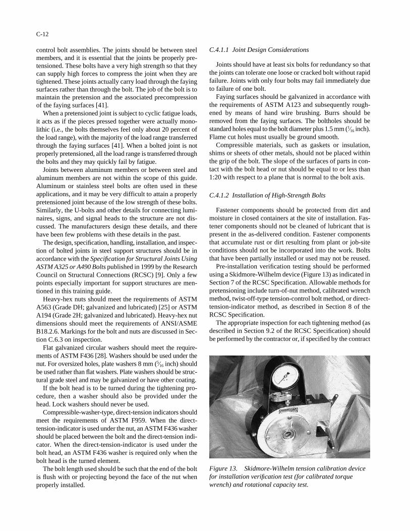
control bolt assemblies. The joints should be between steelmembers, and it is essential that the joints be properly pre-tensioned. These bolts have a very high strength so that theycan supply high forces to compress the joint when they aretightened. These joints actually carry load through the fayingsurfaces rather than through the bolt. The job of the bolt is tomaintain the pretension and the associated precompressionof the faying surfaces [41].
When a pretensioned joint is subject to cyclic fatigue loads,it acts as if the pieces pressed together were actually mono-lithic (i.e., the bolts themselves feel only about 20 percent ofthe load range), with the majority of the load range transferredthrough the faying surfaces [41]. When a bolted joint is notproperly pretensioned, all the load range is transferred throughthe bolts and they may quickly fail by fatigue.
Joints between aluminum members or between steel andaluminum members are not within the scope of this guide.Aluminum or stainless steel bolts are often used in theseapplications, and it may be very difficult to attain a properlypretensioned joint because of the low strength of these bolts.Similarly, the U-bolts and other details for connecting lumi-naires, signs, and signal heads to the structure are not dis-cussed. The manufacturers design these details, and therehave been few problems with these details in the past.
The design, specification, handling, installation, and inspec-tion of bolted joints in steel support structures should be inaccordance with the Specification for Structural Joints UsingASTM A325 or A490 Bolts published in 1999 by the ResearchCouncil on Structural Connections (RCSC) [9]. Only a fewpoints especially important for support structures are men-tioned in this training guide.
Heavy-hex nuts should meet the requirements of ASTMA563 (Grade DH; galvanized and lubricated) [25] or ASTMA194 (Grade 2H; galvanized and lubricated). Heavy-hex nutdimensions should meet the requirements of ANSI/ASMEB18.2.6. Markings for the bolt and nuts are discussed in Sec-tion C.6.3 on inspection.
Flat galvanized circular washers should meet the require-ments of ASTM F436 [28]. Washers should be used under thenut. For oversized holes, plate washers 8 mm (5⁄16 inch) shouldbe used rather than flat washers. Plate washers should be struc-tural grade steel and may be galvanized or have other coating.
If the bolt head is to be turned during the tightening pro-cedure, then a washer should also be provided under thehead. Lock washers should never be used.
Compressible-washer-type, direct-tension indicators shouldmeet the requirements of ASTM F959. When the direct-tension-indicator is used under the nut, an ASTM F436 washershould be placed between the bolt and the direct-tension indi-cator. When the direct-tension-indicator is used under thebolt head, an ASTM F436 washer is required only when thebolt head is the turned element.
The bolt length used should be such that the end of the boltis flush with or projecting beyond the face of the nut whenproperly installed.
C-12
C.4.1.1 Joint Design Considerations
Joints should have at least six bolts for redundancy so thatthe joints can tolerate one loose or cracked bolt without rapidfailure. Joints with only four bolts may fail immediately dueto failure of one bolt.
Faying surfaces should be galvanized in accordance withthe requirements of ASTM A123 and subsequently rough-ened by means of hand wire brushing. Burrs should beremoved from the faying surfaces. The boltholes should bestandard holes equal to the bolt diameter plus 1.5 mm (1⁄16 inch).Flame cut holes must usually be ground smooth.
Compressible materials, such as gaskets or insulation,shims or sheets of other metals, should not be placed withinthe grip of the bolt. The slope of the surfaces of parts in con-tact with the bolt head or nut should be equal to or less than1:20 with respect to a plane that is normal to the bolt axis.
C.4.1.2 Installation of High-Strength Bolts
Fastener components should be protected from dirt andmoisture in closed containers at the site of installation. Fas-tener components should not be cleaned of lubricant that ispresent in the as-delivered condition. Fastener componentsthat accumulate rust or dirt resulting from plant or job-siteconditions should not be incorporated into the work. Boltsthat have been partially installed or used may not be reused.
Pre-installation verification testing should be performedusing a Skidmore-Wilhelm device (Figure 13) as indicated inSection 7 of the RCSC Specification. Allowable methods forpretensioning include turn-of-nut method, calibrated wrenchmethod, twist-off-type tension-control bolt method, or direct-tension-indicator method, as described in Section 8 of theRCSC Specification.
The appropriate inspection for each tightening method (asdescribed in Section 9.2 of the RCSC Specification) shouldbe performed by the contractor or, if specified by the contract
Figure 13. Skidmore-Wilhelm tension calibration devicefor installation verification test (for calibrated torquewrench) and rotational capacity test.
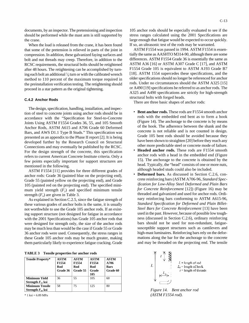
documents, by an inspector. The pretensioning and inspectionshould be performed while the mast arm is still supported bythe crane.
When the load is released from the crane, it has been foundthat some of the pretension is relieved in parts of the joint incompression. In addition, these galvanized faying surfaces andbolt and nut threads may creep. Therefore, in addition to theRCSC requirements, the structural bolts should be retightenedafter 48 hours. The retightening can be accomplished by turn-ing each bolt an additional 1⁄8 turn or with the calibrated wrenchmethod to 110 percent of the maximum torque required inthe preinstallation verification testing. The retightening shouldproceed in a star pattern as the original tightening.
C.4.2 Anchor Rods
The design, specification, handling, installation, and inspec-tion of steel to concrete joints using anchor rods should be inaccordance with the “Specification for Steel-to-ConcreteJoints Using ASTM F1554 Grades 36, 55, and 105 SmoothAnchor Rods, ASTM A615 and A706 Grade 60 DeformedBars, and AWS D1.1 Type B Studs.” This specification waspresented as an appendix to the Phase II report [2]. It is beingdeveloped further by the Research Council on StructuralConnections and may eventually be published by the RCSC.For the design strength of the concrete, this specificationrefers to current American Concrete Institute criteria. Only afew points especially important for support structures arementioned in the following.
ASTM F1554 [11] provides for three different grades ofanchor rods: Grade 36 (painted blue on the projecting end),Grade 55 (painted yellow on the projecting end), and Grade105 (painted red on the projecting end). The specified mini-mum yield strength (Fy) and specified minimum tensilestrength (Fu) are given in Table 3.
As explained in Section C.2.5, since the fatigue strength ofthese various grades of anchor bolts is the same, it is usuallynot worthwhile to use the Grade 105 anchor rods. If an exist-ing support structure (not designed for fatigue in accordancewith the 2001 Specifications) has Grade 105 anchor rods thatwere designed for strength only, the size of the anchor rodsmay be much less than would be the case if Grade 55 or Grade36 anchor rods were used. Consequently, the stress ranges inthese Grade 105 anchor rods may be much greater, makingthem particularly likely to experience fatigue cracking. Grade
C-13
105 anchor rods should be especially evaluated to see if thestress ranges calculated using the 2001 Specifications arelarge enough that fatigue would be expected to occur quickly.If so, an ultrasonic test of the rods may be warranted.
ASTM F1554 was passed in 1994. ASTM F1554 is essen-tially the same as AASHTO M314-90, although there are somedifferences. ASTM F1554 Grade 36 is essentially the same asASTM A36 [16] or ASTM A307 Grade C [17], and ASTMF1554 Grade 105 is equivalent to ASTM A193 Grade B7[18]. ASTM 1554 supercedes these specifications, and theolder specifications should no longer be referenced for anchorrods. Under no circumstances should the ASTM A325 [15]or A490 [19] specifications be referred to as anchor rods. TheA325 and A490 specifications are strictly for high-strengthstructural bolts with forged heads.
There are three basic shapes of anchor rods:
• Bent anchor rods. These rods are F1554 smooth anchorrods with the embedded end bent as to form a hook(Figure 14). The anchorage to the concrete is by meansof the hook. The adherence between the shank and theconcrete is not reliable and is not counted in design.Grade 105 bent rods should be avoided because theyhave been shown to straighten [20] before they reach anyother more predictable steel or concrete mode of failure.
• Headed anchor rods. These rods are F1554 smoothanchor rods with a head in the embedded end (Figure15). The anchorage to the concrete is obtained by thehead. Typically, the “head” consists of one or more nuts,although headed studs could also be included.
• Deformed bars. As discussed in Section C.2.6, con-crete reinforcing bars (ASTM A706-96, Standard Spec-ification for Low-Alloy Steel Deformed and Plain Barsfor Concrete Reinforcement [12]) (Figure 16) may bethreaded and galvanized and used for anchor rods. Ordi-nary reinforcing bars conforming to ASTM A615-96,Standard Specification for Deformed and Plain Billet-Steel Bars for Concrete Reinforcement [13] have beenused in the past. However, because of possible low tough-ness (discussed in Section C.2.6), ordinary reinforcingbars should not be used for non-redundant, fatigue-susceptible support structures such as cantilevers andhigh-mast luminaires. Reinforcing bars rely on the defor-mations along the bar for the anchorage to the concreteand may be threaded on the projecting end. The tensile
Tensile Property* ASTM F1554 Rod Grade 36
ASTM F1554 Rod Grade 55
ASTM F1554 Rod Grade 105
ASTM A706 Bars Grade 60
Minimum Yield Strength Fy, ksi
36 55 105 60
Minimum Tensile Strength Fu, ksi
58 75 125 80
* 1 ksi = 6.89 MPa
TABLE 3 Tensile properties for anchor rods
Figure 14. Bent anchor rod(ASTM F1554 rod).
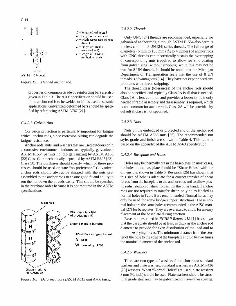
properties of common Grade 60 reinforcing bars are alsogiven in Table 3. The A706 specification should be usedif the anchor rod is to be welded or if it is used in seismicapplications. Galvanized deformed bars should be speci-fied by referencing ASTM A767 [21].
C.4.2.1 Galvanizing
Corrosion protection is particularly important for fatiguecritical anchor rods, since corrosion pitting can degrade thefatigue resistance.
Anchor rods, nuts, and washers that are used outdoors or ina corrosive environment indoors are typically galvanized.ASTM F1554 permits hot dip galvanizing by ASTM A153[22] Class C or mechanically deposited by ASTM B695 [23],Class 50. The purchaser should specify which of these pro-cesses should be used or state “no preference.” Galvanizedanchor rods should always be shipped with the nuts pre-assembled to the anchor rods to ensure good fit and ability torun the nut down the threads easily. This should be specifiedin the purchase order because it is not required in the ASTMspecifications.
C-14
C.4.2.2 Threads
Only UNC [24] threads are recommended, especially forgalvanized anchor rods, although ASTM F1554 also permitsthe less common 8 UN [24] series threads. The full range ofdiameters (6 mm to 100 mm) (1⁄4 to 4 inches) of anchor rodswith UNC threads can theoretically sustain the overtappingof corresponding nuts (required to allow for zinc coatingfrom galvanizing) without stripping, while this may not betrue for 8 UN threads. It should be noted that the MichiganDepartment of Transportation feels that the use of 8 UNthreads is advantageous [14]. They have not experienced anyproblems with thread stripping.
The thread class (tolerances) of the anchor rods shouldalso be specified, and typically Class 2A is all that is needed.Class 1A is less common and provides a looser fit. It is onlyneeded if rapid assembly and disassembly is required, whichis not common for anchor rods. Class 2A will be provided bydefault if class is not specified.
C.4.2.3 Nuts
Nuts on the embedded or projected end of the anchor rodshould be ASTM A563 nuts [25]. The recommended nutstyle, grade and finish are shown in Table 4. This table isbased on the appendix of the ASTM A563 specification.
C.4.2.4 Baseplate and Holes
Holes may be thermally cut in the baseplates. In most cases,the holes in the baseplate should be “Shear Holes” with thedimensions shown in Table 5. Research [26] has shown thatthis size of hole is adequate for a correct transfer of shearforces from the baseplate to the anchor rods and to allow plas-tic redistribution of shear forces. On the other hand, if anchorrods are not required to transfer shear, only holes labeled asnormal holes in Table 5 are recommended. Normal holes mayonly be used for some bridge support structures. These nor-mal holes are the same holes recommended in the AISC man-ual [27] for baseplates. They are oversized to allow for an easyplacement of the baseplate during erection.
Research described in NCHRP Report 412 [1] has shownthat the baseplate should be at least as thick as the anchor roddiameter to provide for even distribution of the load and tominimize prying forces. The minimum distance from the cen-ter of the hole to the edge of the baseplate should be two timesthe nominal diameter of the anchor rod.
C.4.2.5 Washers
There are two types of washers for anchor rods: standardwashers and plate washers. Standard washers are ASTM F436[28] washers. When “Normal Holes” are used, plate washers8 mm (5⁄16 inch) should be used. Plate washers should be struc-tural grade steel and may be galvanized or have other coating.
Figure 15. Headed anchor rod.
Figure 16. Deformed bars (ASTM A615 and A706 bars).
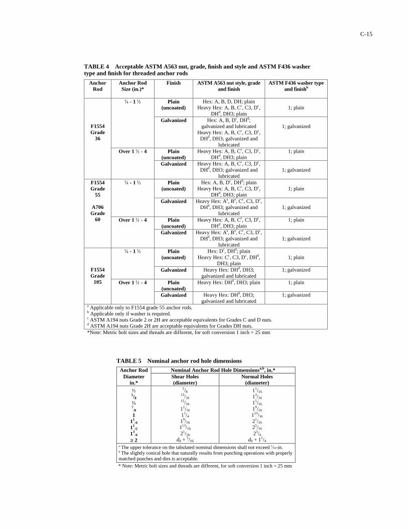
Anchor Rod
Anchor Rod Size (in.)*
Finish ASTM A563 nut style, grade and finish
ASTM F436 washer type and finishb
Plain (uncoated)
Hex: A, B, D, DH; plain Heavy Hex: A, B, Cc, C3, Dc,
DHd, DH3; plain
1; plain
1⁄4 - 1 1⁄2
Galvanized Hex: A, B, Dc, DHd; galvanized and lubricated
Heavy Hex: A, B, Cc, C3, Dc, DHd, DH3; galvanized and
lubricated
1; galvanized
Plain (uncoated)
Heavy Hex: A, B, Cc, C3, Dc, DHd, DH3; plain
1; plain
F1554 Grade
36
Over 1 1⁄2 - 4
Galvanized Heavy Hex: A, B, Cc, C3, Dc, DHd, DH3; galvanized and
lubricated
1; galvanized
Plain (uncoated)
Hex: A, B, Dc, DHd; plain Heavy Hex: A, B, Cc, C3, Dc,
DHd, DH3; plain
1; plain
1⁄4 - 1 1⁄2
Galvanized Heavy Hex: Aa, Ba, Cc, C3, Dc, DHd, DH3; galvanized and
lubricated
1; galvanized
Plain (uncoated)
Heavy Hex: A, B, Cc, C3, Dc, DHd, DH3; plain
1; plain
F1554 Grade
55
A706 Grade
60 Over 1 1⁄2 - 4
Galvanized Heavy Hex: Aa, Ba, Cc, C3, Dc, DHd, DH3; galvanized and
lubricated
1; galvanized
Plain (uncoated)
Hex: Dc, DHd; plain Heavy Hex: Cc, C3, Dc, DHd,
DH3; plain
1; plain
1⁄4 - 1 1⁄2
Galvanized Heavy Hex: DHd, DH3; galvanized and lubricated
1; galvanized
Plain (uncoated)
Heavy Hex: DHd, DH3; plain 1; plain
F1554 Grade
105 Over 1 1⁄2 - 4
Galvanized Heavy Hex: DHd, DH3; galvanized and lubricated
1; galvanized
a Applicable only to F1554 grade 55 anchor rods. b Applicable only if washer is required. c ASTM A194 nuts Grade 2 or 2H are acceptable equivalents for Grades C and D nuts. d ASTM A194 nuts Grade 2H are acceptable equivalents for Grades DH nuts. *Note: Metric bolt sizes and threads are different, for soft conversion 1 inch = 25 mm
TABLE 4 Acceptable ASTM A563 nut, grade, finish and style and ASTM F436 washer type and finish for threaded anchor rods
Anchor Rod Nominal Anchor Rod Hole Dimensionsa,b, in.* Diameter
in.* Shear Holes (diameter)
Normal Holes (diameter)
1⁄2 5/8 3⁄4 7
/8 1
11/4
11/2
13/4
≥ 2
5/8 13/16 15/16 11/16 11/4 19/16 113/16
21/16 db + 5/16
11/16 13/16 15/16 19/16 113/16 21/16 25/16 23/4
db + 11/4
* Note: Metric bolt sizes and threads are different, for soft conversion 1 inch = 25 mm
a The upper tolerance on the tabulated nominal dimensions shall not exceed 1⁄16-in. b The slightly conical hole that naturally results from punching operations with properly matched punches and dies is acceptable.
TABLE 5 Nominal anchor rod hole dimensions
C-15
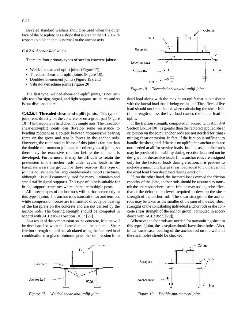
Beveled standard washers should be used when the outerface of the baseplate has a slope that is greater than 1:20 withrespect to a plane that is normal to the anchor axis.
C.4.2.6 Anchor Rod Joints
There are four primary types of steel to concrete joints:
• Welded-shear-and-uplift joints (Figure 17),• Threaded-shear-and-uplift joints (Figure 18),• Double-nut-moment joints (Figure 19), and• Vibratory-machine joints (Figure 20).
The first type, welded-shear-and-uplift joints, is not usu-ally used for sign, signal, and light support structures and sois not discussed here.
C.4.2.6.1 Threaded-shear-and-uplift joints. This type ofjoint rests directly on the concrete or on a grout pad (Figure18). The baseplate is held down by single nuts. The threaded-shear-and-uplift joints can develop some resistance tobending moment as a couple between compressive bearingforce on the grout and tensile forces in the anchor rods.However, the rotational stiffness of this joint is far less thanthe double-nut-moment joint and the other types of joints, sothere may be excessive rotation before the moment isdeveloped. Furthermore, it may be difficult to retain thepretension in the anchor rods under cyclic loads as thebaseplate wears the grout. For these reasons, this type ofjoint is not suitable for large cantilevered support structures,although it is still commonly used for many luminaires andsmall traffic signal supports. This type of joint is suitable forbridge support structures where there are multiple posts.
All three shapes of anchor rods will perform correctly inthis type of joint. The anchor rods transmit shear and tension,while compression forces are transmitted directly by bearingof the baseplate on the concrete and are not carried by theanchor rods. The bearing strength should be computed inaccord with ACI 318-99 Section 10.17 [29].
As a result of the compression on the concrete, friction willbe developed between the baseplate and the concrete. Shearfriction strength should be calculated using the factored loadcombination that gives minimum possible compression from
C-16
dead load along with the maximum uplift that is consistentwith the lateral load that is being evaluated. The effect of liveload should not be included when calculating the shear fric-tion strength unless the live load causes the lateral load oruplift.
If the friction strength, computed in accord with ACI 349Section B6.1.4 [30], is greater than the factored applied shearor torsion on the joint, anchor rods are not needed for trans-mitting shear or torsion. In fact, if the friction is sufficient tohandle the shear, and if there is no uplift, then anchor rods arenot needed at all for service loads. In this case, anchor rodsmay be provided for stability during erection but need not bedesigned for the service loads. If the anchor rods are designedonly for the factored loads during erection, it is prudent toinclude a minimum lateral shear load equal to 5.0 percent ofthe axial load from dead load during erection.
If, on the other hand, the factored loads exceed the frictioncapacity of the joint, anchor rods should be assumed to trans-mit the entire shear because the friction may no longer be effec-tive at the deformation levels required to develop the shearstrength of the anchor rods. The shear strength of the anchorrods may be taken as the smaller of the sum of the steel shearstrengths of the contributing individual anchor rods or the con-crete shear strength of the anchor group (computed in accor-dance with ACI 318-99 [29]).
Whenever anchor rods are needed for transmitting shear inthis type of joint, the baseplate should have shear holes. Also,in the same case, bearing of the anchor rod on the walls ofthe shear holes should be checked.
Figure 18. Threaded-shear-and-uplift joint.
Figure 19. Double-nut-moment joint.Figure 17. Welded-shear-and-uplift joint.
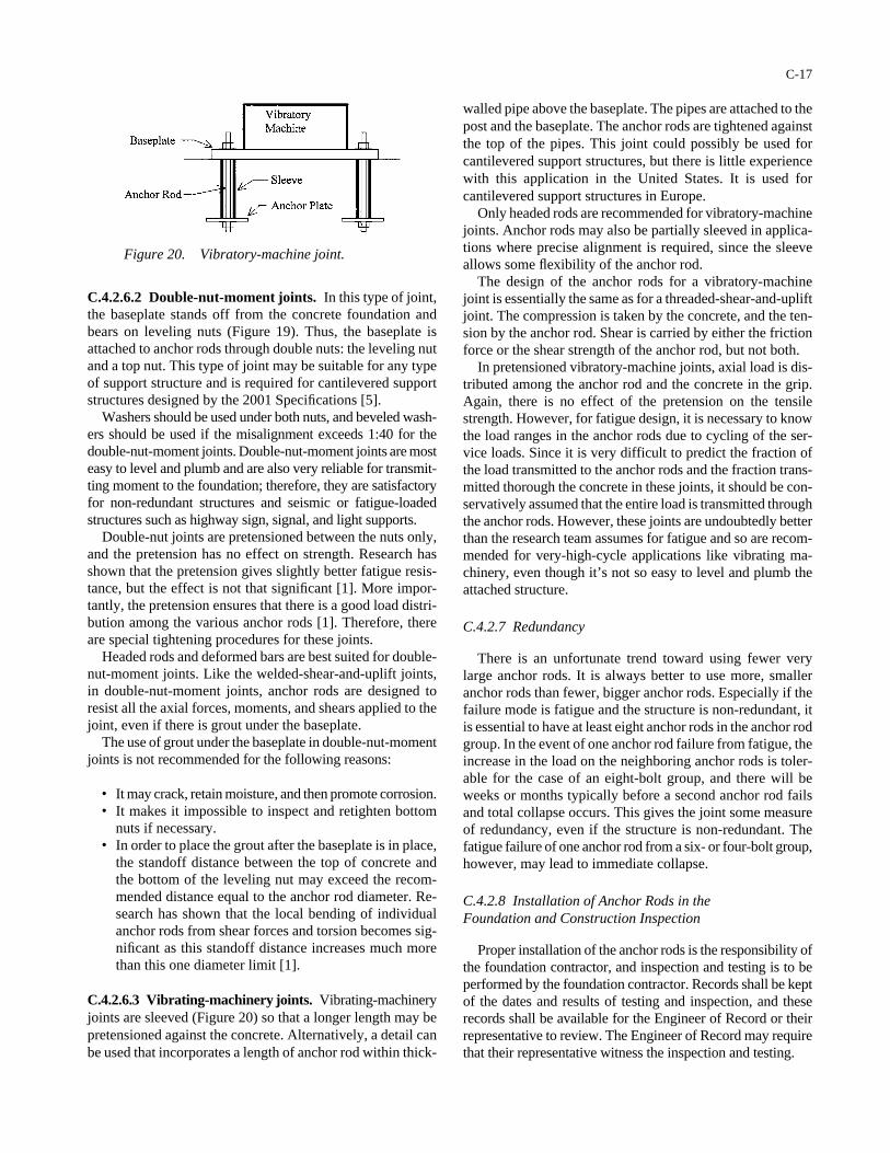
C.4.2.6.2 Double-nut-moment joints. In this type of joint,the baseplate stands off from the concrete foundation andbears on leveling nuts (Figure 19). Thus, the baseplate isattached to anchor rods through double nuts: the leveling nutand a top nut. This type of joint may be suitable for any typeof support structure and is required for cantilevered supportstructures designed by the 2001 Specifications [5].
Washers should be used under both nuts, and beveled wash-ers should be used if the misalignment exceeds 1:40 for thedouble-nut-moment joints. Double-nut-moment joints are mosteasy to level and plumb and are also very reliable for transmit-ting moment to the foundation; therefore, they are satisfactoryfor non-redundant structures and seismic or fatigue-loadedstructures such as highway sign, signal, and light supports.
Double-nut joints are pretensioned between the nuts only,and the pretension has no effect on strength. Research hasshown that the pretension gives slightly better fatigue resis-tance, but the effect is not that significant [1]. More impor-tantly, the pretension ensures that there is a good load distri-bution among the various anchor rods [1]. Therefore, thereare special tightening procedures for these joints.
Headed rods and deformed bars are best suited for double-nut-moment joints. Like the welded-shear-and-uplift joints,in double-nut-moment joints, anchor rods are designed toresist all the axial forces, moments, and shears applied to thejoint, even if there is grout under the baseplate.
The use of grout under the baseplate in double-nut-momentjoints is not recommended for the following reasons:
• It may crack, retain moisture, and then promote corrosion.• It makes it impossible to inspect and retighten bottom
nuts if necessary.• In order to place the grout after the baseplate is in place,
the standoff distance between the top of concrete andthe bottom of the leveling nut may exceed the recom-mended distance equal to the anchor rod diameter. Re-search has shown that the local bending of individualanchor rods from shear forces and torsion becomes sig-nificant as this standoff distance increases much morethan this one diameter limit [1].
C.4.2.6.3 Vibrating-machinery joints. Vibrating-machineryjoints are sleeved (Figure 20) so that a longer length may bepretensioned against the concrete. Alternatively, a detail canbe used that incorporates a length of anchor rod within thick-
C-17
walled pipe above the baseplate. The pipes are attached to thepost and the baseplate. The anchor rods are tightened againstthe top of the pipes. This joint could possibly be used forcantilevered support structures, but there is little experiencewith this application in the United States. It is used forcantilevered support structures in Europe.
Only headed rods are recommended for vibratory-machinejoints. Anchor rods may also be partially sleeved in applica-tions where precise alignment is required, since the sleeveallows some flexibility of the anchor rod.
The design of the anchor rods for a vibratory-machinejoint is essentially the same as for a threaded-shear-and-upliftjoint. The compression is taken by the concrete, and the ten-sion by the anchor rod. Shear is carried by either the frictionforce or the shear strength of the anchor rod, but not both.
In pretensioned vibratory-machine joints, axial load is dis-tributed among the anchor rod and the concrete in the grip.Again, there is no effect of the pretension on the tensilestrength. However, for fatigue design, it is necessary to knowthe load ranges in the anchor rods due to cycling of the ser-vice loads. Since it is very difficult to predict the fraction ofthe load transmitted to the anchor rods and the fraction trans-mitted thorough the concrete in these joints, it should be con-servatively assumed that the entire load is transmitted throughthe anchor rods. However, these joints are undoubtedly betterthan the research team assumes for fatigue and so are recom-mended for very-high-cycle applications like vibrating ma-chinery, even though it’s not so easy to level and plumb theattached structure.
C.4.2.7 Redundancy
There is an unfortunate trend toward using fewer verylarge anchor rods. It is always better to use more, smalleranchor rods than fewer, bigger anchor rods. Especially if thefailure mode is fatigue and the structure is non-redundant, itis essential to have at least eight anchor rods in the anchor rodgroup. In the event of one anchor rod failure from fatigue, theincrease in the load on the neighboring anchor rods is toler-able for the case of an eight-bolt group, and there will beweeks or months typically before a second anchor rod failsand total collapse occurs. This gives the joint some measureof redundancy, even if the structure is non-redundant. Thefatigue failure of one anchor rod from a six- or four-bolt group,however, may lead to immediate collapse.
C.4.2.8 Installation of Anchor Rods in theFoundation and Construction Inspection
Proper installation of the anchor rods is the responsibility ofthe foundation contractor, and inspection and testing is to beperformed by the foundation contractor. Records shall be keptof the dates and results of testing and inspection, and theserecords shall be available for the Engineer of Record or theirrepresentative to review. The Engineer of Record may requirethat their representative witness the inspection and testing.
Figure 20. Vibratory-machine joint.
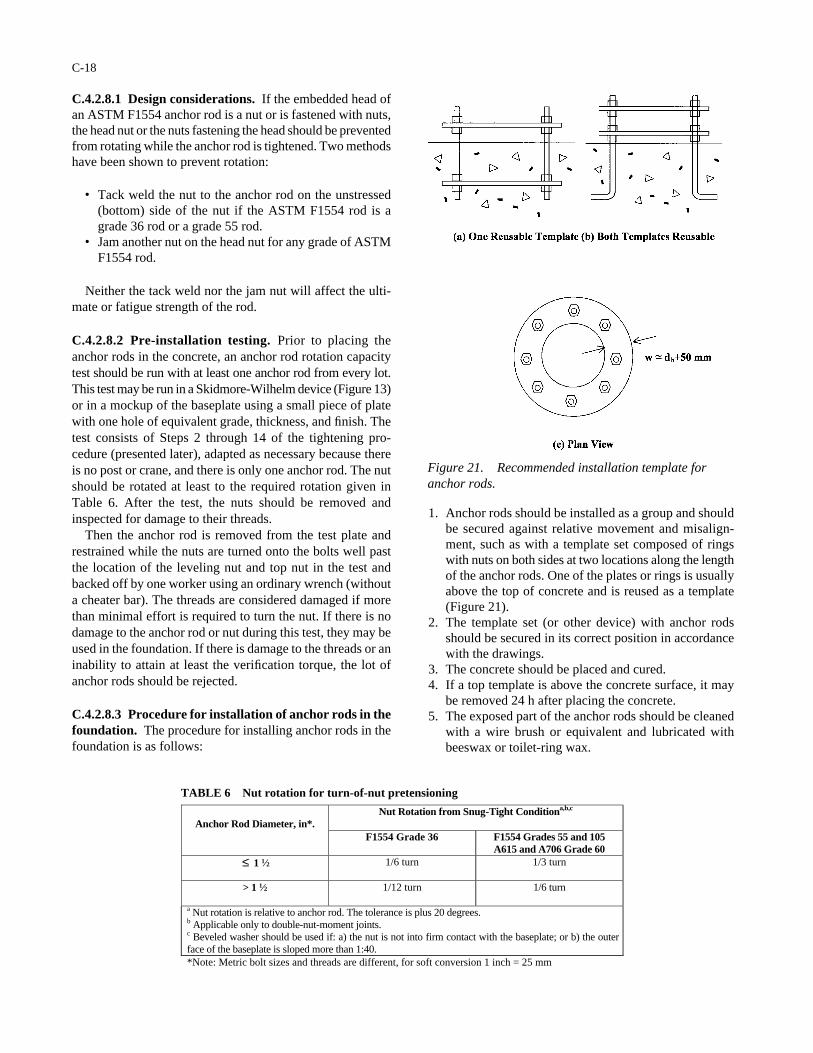
C.4.2.8.1 Design considerations. If the embedded head ofan ASTM F1554 anchor rod is a nut or is fastened with nuts,the head nut or the nuts fastening the head should be preventedfrom rotating while the anchor rod is tightened. Two methodshave been shown to prevent rotation:
• Tack weld the nut to the anchor rod on the unstressed(bottom) side of the nut if the ASTM F1554 rod is agrade 36 rod or a grade 55 rod.
• Jam another nut on the head nut for any grade of ASTMF1554 rod.
Neither the tack weld nor the jam nut will affect the ulti-mate or fatigue strength of the rod.
C.4.2.8.2 Pre-installation testing. Prior to placing theanchor rods in the concrete, an anchor rod rotation capacitytest should be run with at least one anchor rod from every lot.This test may be run in a Skidmore-Wilhelm device (Figure 13)or in a mockup of the baseplate using a small piece of platewith one hole of equivalent grade, thickness, and finish. Thetest consists of Steps 2 through 14 of the tightening pro-cedure (presented later), adapted as necessary because thereis no post or crane, and there is only one anchor rod. The nutshould be rotated at least to the required rotation given inTable 6. After the test, the nuts should be removed andinspected for damage to their threads.
Then the anchor rod is removed from the test plate andrestrained while the nuts are turned onto the bolts well pastthe location of the leveling nut and top nut in the test andbacked off by one worker using an ordinary wrench (withouta cheater bar). The threads are considered damaged if morethan minimal effort is required to turn the nut. If there is nodamage to the anchor rod or nut during this test, they may beused in the foundation. If there is damage to the threads or aninability to attain at least the verification torque, the lot ofanchor rods should be rejected.
C.4.2.8.3 Procedure for installation of anchor rods in thefoundation. The procedure for installing anchor rods in thefoundation is as follows:
C-18
1. Anchor rods should be installed as a group and shouldbe secured against relative movement and misalign-ment, such as with a template set composed of ringswith nuts on both sides at two locations along the lengthof the anchor rods. One of the plates or rings is usuallyabove the top of concrete and is reused as a template(Figure 21).
2. The template set (or other device) with anchor rodsshould be secured in its correct position in accordancewith the drawings.
3. The concrete should be placed and cured.4. If a top template is above the concrete surface, it may
be removed 24 h after placing the concrete.5. The exposed part of the anchor rods should be cleaned
with a wire brush or equivalent and lubricated withbeeswax or toilet-ring wax.
Nut Rotation from Snug-Tight Conditiona,b,c Anchor Rod Diameter, in*.
F1554 Grade 36 F1554 Grades 55 and 105 A615 and A706 Grade 60
≤ 1 1⁄2 1/6 turn 1/3 turn
> 1 1⁄2 1/12 turn 1/6 turn
a Nut rotation is relative to anchor rod. The tolerance is plus 20 degrees. b Applicable only to double-nut-moment joints. c Beveled washer should be used if: a) the nut is not into firm contact with the baseplate; or b) the outer face of the baseplate is sloped more than 1:40. *Note: Metric bolt sizes and threads are different, for soft conversion 1 inch = 25 mm
Figure 21. Recommended installation template foranchor rods.
TABLE 6 Nut rotation for turn-of-nut pretensioning

6. After at least 24 h, the anchor rods should be inspectedvisually to verify that there is no visible damage to thethreads and that their position, elevation, and projectedlength is within the tolerances of the AISC Code ofStandard Practice for Steel Buildings and Bridges [8];and that the misalignment from vertical is no more than1:40. It is good practice to use a steel or wood templatewith the hole pattern to check the base of the post andthe anchor rods. The nuts should be turned onto therods well past the elevation of the bottom of the level-ing nut and backed off by one worker using an ordinarywrench without a cheater bar.
7. Once the concrete has reached sufficient strength (from7 to 28 days), anchor rods are ready to be subjected toerection loads.
The tightening procedure for the anchor rods is discussedin the following section.
C.5 ERECTION OF SIGN, SIGNAL, AND LIGHTSUPPORT STRUCTURES
C.5.1 Scope and Responsibility
This section recommends specific procedures for theerection of the support structures. Construction of the con-crete foundations is not covered. However, there is exten-sive guidance on the proper installation of anchor rods inSection C.4.2.
Detailed rigging and safety issues are not covered in thisguide; these issues are common to any construction projectand are governed by relevant state, agency, and AASHTOconstruction and materials specifications. In general, onlyissues that can affect the vibration and fatigue performanceof the structure after erection are covered in this section.
Proper erection is the responsibility of the erection con-tractor. The erection contractor should perform inspectionand testing. Records shall be kept of the dates and results ofinspection, and these records shall be available for the Engi-neer of Record or their representative to review. The Engi-neer of Record may require that their representative witnessthe installation and inspection.
The erection contractor must inspect the anchor rods toensure that they were installed as required in the drawings.Corrections to out-of-position anchor rods must be handledon a case-by-case basis, as described in Section C.7.3.
C.5.2 Preparation for Erection
The erection contractor is responsible for assemblingdesign and fabrication documents and having them availablefor review by the owner, Engineer of Record, or their repre-sentative. The design and fabrication documents shouldinclude a set of design drawings; shop drawings; the nameand contact information for the designer/consultant of record;design calculations (stamped by a professional engineer
C-19
explicitly showing the fatigue design as well as the tradi-tional allowable stress design for strength); the name andcontact information (including location of plant) of fabrica-tor of record; welding procedure specifications; inspectionreports; and copies of material mill certificates for the anchorrods, structural bolts, and the main members (not includingstiffeners, baseplates, flange plates, and other small plates).
The erection contractor, considering the weight and stabil-ity of the pieces to be erected, should carefully plan the erec-tion procedure for each job. Light poles, including light sup-ports with cantilevered arms, may usually be fully assembledon the ground and erected in one piece. Cantilevered sign andsignal supports should be erected in two pieces. It has beenfound that it is nearly impossible to properly tighten the dou-ble-nut anchor rod connection when a completely assembledcantilevered support structure is suspended from the crane.
Prior to erection, the separate parts of the structure (the postand the cantilevered mast arm or truss) should be inspected.The weld quality should conform to AWS D1.1, StructuralWelding Code—Steel [7]. Fillet welds should be checked witha fillet weld gauge. The galvanized coating should beinspected, and inadequate portions of the coating should berepaired in a manner consistent with ASTM A-780 [33].
Various weld inspections are required in Section 5.15 ofthe 2001 Specifications [5] as explained below. The specifi-cations also allow as an alternative to these inspections adestructive test that is acceptable to the owner. This alterna-tive may be the best option in view of the expected poor reli-ability of the inspection methods in these applications.
The contractor should verify that these inspections (ordestructive tests) were performed and should have the recordsof these inspections (or tests) available for the Engineer ofRecord or their representative to review. The inspectionrequirements do not apply to small luminaire arms.
The specifications require that all circumferential splicewelds be full-penetration welds and be inspected using eitherradiographic testing (RT) or ultrasonic testing (UT). However,RT is not suitable for detecting cracks perpendicular to theplate surface (the most common and potentially dangeroustypes of weld cracks). It is assumed that backing rings are per-mitted to be used inside the tube. In this case, the ultrasonic testwill give a strong indication at the backing ring, and detectionof flaws will be difficult. Therefore, these techniques shouldnot be viewed as ensuring a weld that is free of defects.
Longitudinal seam welds may be partial-penetration weldswith the exception of certain lengths of the seam welds nearjoints, which must be full penetration. The full-penetrationlengths of seam welds must be inspected using either RT orUT. In addition, a random 25 percent of the partial-penetra-tion welds should be inspected using magnetic particle test-ing (MT). MT is considered a very good technique for find-ing surface cracks.
A random 25 percent of mast arm to flange welds and poleto baseplate welds should be inspected. Full-penetrationwelds should be inspected using RT or UT. Again, thesetechniques would be expected to be ineffective. Fillet welds
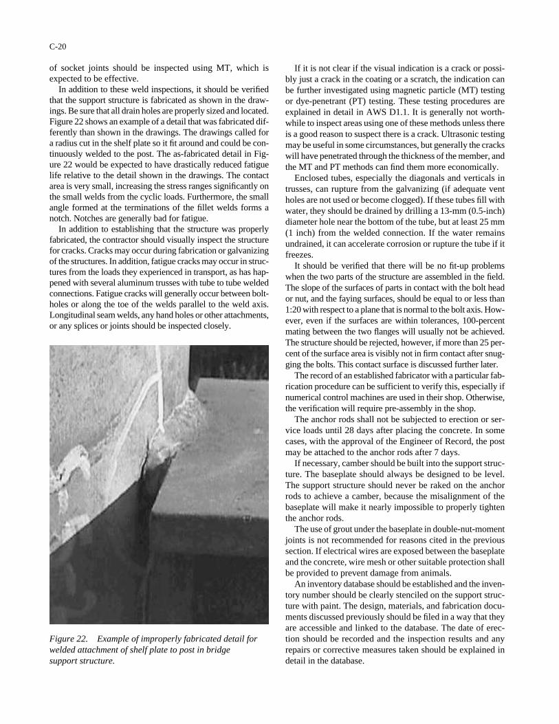
of socket joints should be inspected using MT, which isexpected to be effective.
In addition to these weld inspections, it should be verifiedthat the support structure is fabricated as shown in the draw-ings. Be sure that all drain holes are properly sized and located.Figure 22 shows an example of a detail that was fabricated dif-ferently than shown in the drawings. The drawings called fora radius cut in the shelf plate so it fit around and could be con-tinuously welded to the post. The as-fabricated detail in Fig-ure 22 would be expected to have drastically reduced fatiguelife relative to the detail shown in the drawings. The contactarea is very small, increasing the stress ranges significantly onthe small welds from the cyclic loads. Furthermore, the smallangle formed at the terminations of the fillet welds forms anotch. Notches are generally bad for fatigue.
In addition to establishing that the structure was properlyfabricated, the contractor should visually inspect the structurefor cracks. Cracks may occur during fabrication or galvanizingof the structures. In addition, fatigue cracks may occur in struc-tures from the loads they experienced in transport, as has hap-pened with several aluminum trusses with tube to tube weldedconnections. Fatigue cracks will generally occur between bolt-holes or along the toe of the welds parallel to the weld axis.Longitudinal seam welds, any hand holes or other attachments,or any splices or joints should be inspected closely.
C-20
If it is not clear if the visual indication is a crack or possi-bly just a crack in the coating or a scratch, the indication canbe further investigated using magnetic particle (MT) testingor dye-penetrant (PT) testing. These testing procedures areexplained in detail in AWS D1.1. It is generally not worth-while to inspect areas using one of these methods unless thereis a good reason to suspect there is a crack. Ultrasonic testingmay be useful in some circumstances, but generally the crackswill have penetrated through the thickness of the member, andthe MT and PT methods can find them more economically.
Enclosed tubes, especially the diagonals and verticals intrusses, can rupture from the galvanizing (if adequate ventholes are not used or become clogged). If these tubes fill withwater, they should be drained by drilling a 13-mm (0.5-inch)diameter hole near the bottom of the tube, but at least 25 mm(1 inch) from the welded connection. If the water remainsundrained, it can accelerate corrosion or rupture the tube if itfreezes.
It should be verified that there will be no fit-up problemswhen the two parts of the structure are assembled in the field.The slope of the surfaces of parts in contact with the bolt heador nut, and the faying surfaces, should be equal to or less than1:20 with respect to a plane that is normal to the bolt axis. How-ever, even if the surfaces are within tolerances, 100-percentmating between the two flanges will usually not be achieved.The structure should be rejected, however, if more than 25 per-cent of the surface area is visibly not in firm contact after snug-ging the bolts. This contact surface is discussed further later.
The record of an established fabricator with a particular fab-rication procedure can be sufficient to verify this, especially ifnumerical control machines are used in their shop. Otherwise,the verification will require pre-assembly in the shop.
The anchor rods shall not be subjected to erection or ser-vice loads until 28 days after placing the concrete. In somecases, with the approval of the Engineer of Record, the postmay be attached to the anchor rods after 7 days.
If necessary, camber should be built into the support struc-ture. The baseplate should always be designed to be level.The support structure should never be raked on the anchorrods to achieve a camber, because the misalignment of thebaseplate will make it nearly impossible to properly tightenthe anchor rods.
The use of grout under the baseplate in double-nut-momentjoints is not recommended for reasons cited in the previoussection. If electrical wires are exposed between the baseplateand the concrete, wire mesh or other suitable protection shallbe provided to prevent damage from animals.
An inventory database should be established and the inven-tory number should be clearly stenciled on the support struc-ture with paint. The design, materials, and fabrication docu-ments discussed previously should be filed in a way that theyare accessible and linked to the database. The date of erec-tion should be recorded and the inspection results and anyrepairs or corrective measures taken should be explained indetail in the database.
Figure 22. Example of improperly fabricated detail forwelded attachment of shelf plate to post in bridge support structure.
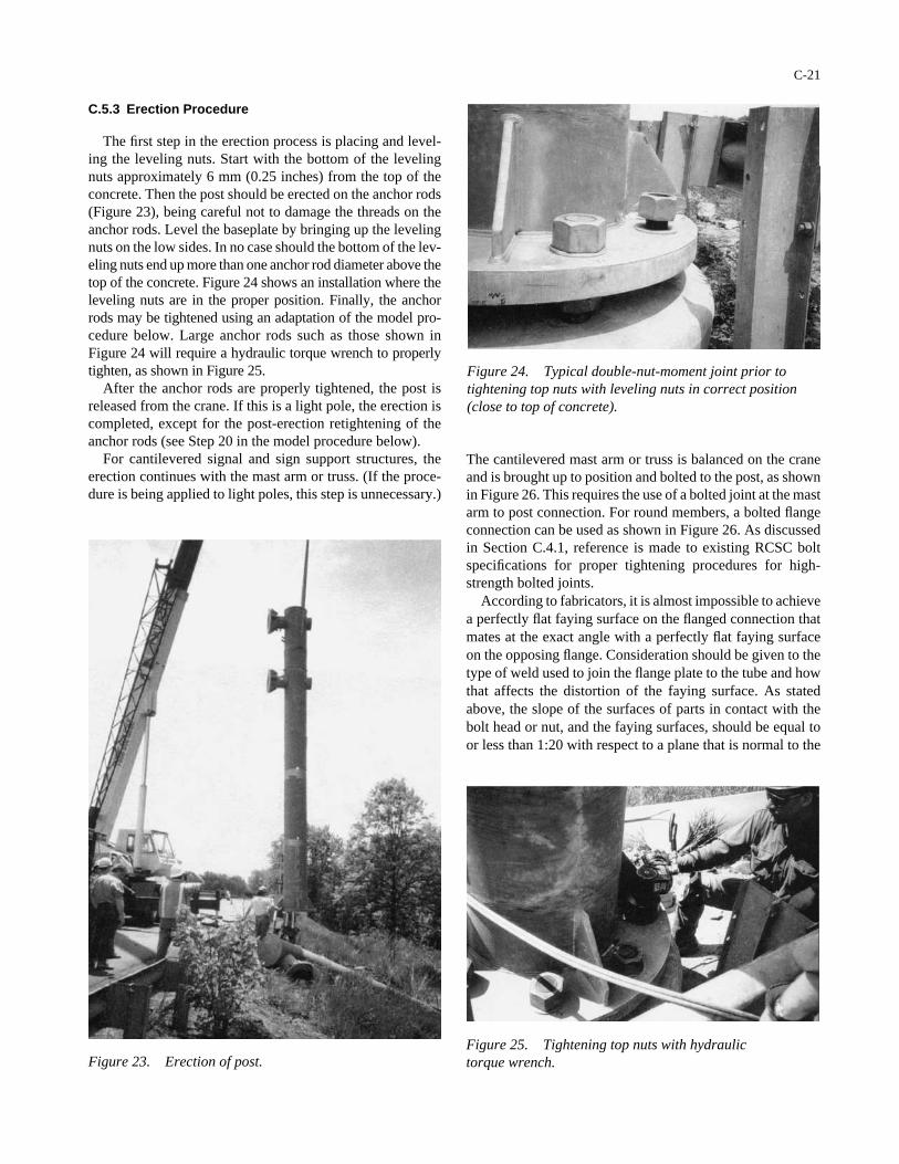
C-21
Figure 23. Erection of post.
Figure 24. Typical double-nut-moment joint prior totightening top nuts with leveling nuts in correct position(close to top of concrete).
Figure 25. Tightening top nuts with hydraulic torque wrench.
C.5.3 Erection Procedure
The first step in the erection process is placing and level-ing the leveling nuts. Start with the bottom of the levelingnuts approximately 6 mm (0.25 inches) from the top of theconcrete. Then the post should be erected on the anchor rods(Figure 23), being careful not to damage the threads on theanchor rods. Level the baseplate by bringing up the levelingnuts on the low sides. In no case should the bottom of the lev-eling nuts end up more than one anchor rod diameter above thetop of the concrete. Figure 24 shows an installation where theleveling nuts are in the proper position. Finally, the anchorrods may be tightened using an adaptation of the model pro-cedure below. Large anchor rods such as those shown inFigure 24 will require a hydraulic torque wrench to properlytighten, as shown in Figure 25.
After the anchor rods are properly tightened, the post isreleased from the crane. If this is a light pole, the erection iscompleted, except for the post-erection retightening of theanchor rods (see Step 20 in the model procedure below).
For cantilevered signal and sign support structures, theerection continues with the mast arm or truss. (If the proce-dure is being applied to light poles, this step is unnecessary.)
The cantilevered mast arm or truss is balanced on the craneand is brought up to position and bolted to the post, as shownin Figure 26. This requires the use of a bolted joint at the mastarm to post connection. For round members, a bolted flangeconnection can be used as shown in Figure 26. As discussedin Section C.4.1, reference is made to existing RCSC boltspecifications for proper tightening procedures for high-strength bolted joints.
According to fabricators, it is almost impossible to achievea perfectly flat faying surface on the flanged connection thatmates at the exact angle with a perfectly flat faying surfaceon the opposing flange. Consideration should be given to thetype of weld used to join the flange plate to the tube and howthat affects the distortion of the faying surface. As statedabove, the slope of the surfaces of parts in contact with thebolt head or nut, and the faying surfaces, should be equal toor less than 1:20 with respect to a plane that is normal to the
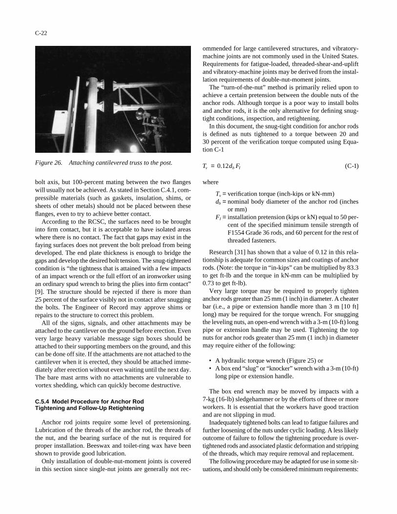
bolt axis, but 100-percent mating between the two flangeswill usually not be achieved. As stated in Section C.4.1, com-pressible materials (such as gaskets, insulation, shims, orsheets of other metals) should not be placed between theseflanges, even to try to achieve better contact.
According to the RCSC, the surfaces need to be broughtinto firm contact, but it is acceptable to have isolated areaswhere there is no contact. The fact that gaps may exist in thefaying surfaces does not prevent the bolt preload from beingdeveloped. The end plate thickness is enough to bridge thegaps and develop the desired bolt tension. The snug-tightenedcondition is “the tightness that is attained with a few impactsof an impact wrench or the full effort of an ironworker usingan ordinary spud wrench to bring the plies into firm contact”[9]. The structure should be rejected if there is more than25 percent of the surface visibly not in contact after snuggingthe bolts. The Engineer of Record may approve shims orrepairs to the structure to correct this problem.
All of the signs, signals, and other attachments may beattached to the cantilever on the ground before erection. Evenvery large heavy variable message sign boxes should beattached to their supporting members on the ground, and thiscan be done off site. If the attachments are not attached to thecantilever when it is erected, they should be attached imme-diately after erection without even waiting until the next day.The bare mast arms with no attachments are vulnerable tovortex shedding, which can quickly become destructive.
C.5.4 Model Procedure for Anchor RodTightening and Follow-Up Retightening
Anchor rod joints require some level of pretensioning.Lubrication of the threads of the anchor rod, the threads ofthe nut, and the bearing surface of the nut is required forproper installation. Beeswax and toilet-ring wax have beenshown to provide good lubrication.
Only installation of double-nut-moment joints is coveredin this section since single-nut joints are generally not rec-
C-22
ommended for large cantilevered structures, and vibratory-machine joints are not commonly used in the United States.Requirements for fatigue-loaded, threaded-shear-and-upliftand vibratory-machine joints may be derived from the instal-lation requirements of double-nut-moment joints.
The “turn-of-the-nut” method is primarily relied upon toachieve a certain pretension between the double nuts of theanchor rods. Although torque is a poor way to install boltsand anchor rods, it is the only alternative for defining snug-tight conditions, inspection, and retightening.
In this document, the snug-tight condition for anchor rodsis defined as nuts tightened to a torque between 20 and 30 percent of the verification torque computed using Equa-tion C-1
where
Tv = verification torque (inch-kips or kN-mm)db = nominal body diameter of the anchor rod (inches
or mm)FI = installation pretension (kips or kN) equal to 50 per-
cent of the specified minimum tensile strength ofF1554 Grade 36 rods, and 60 percent for the rest ofthreaded fasteners.
Research [31] has shown that a value of 0.12 in this rela-tionship is adequate for common sizes and coatings of anchorrods. (Note: the torque in “in-kips” can be multiplied by 83.3to get ft-lb and the torque in kN-mm can be multiplied by0.73 to get ft-lb).
Very large torque may be required to properly tightenanchor rods greater than 25 mm (1 inch) in diameter. A cheaterbar (i.e., a pipe or extension handle more than 3 m [10 ft]long) may be required for the torque wrench. For snuggingthe leveling nuts, an open-end wrench with a 3-m (10-ft) longpipe or extension handle may be used. Tightening the topnuts for anchor rods greater than 25 mm (1 inch) in diametermay require either of the following:
• A hydraulic torque wrench (Figure 25) or• A box end “slug” or “knocker” wrench with a 3-m (10-ft)
long pipe or extension handle.
The box end wrench may be moved by impacts with a 7-kg (16-lb) sledgehammer or by the efforts of three or moreworkers. It is essential that the workers have good tractionand are not slipping in mud.
Inadequately tightened bolts can lead to fatigue failures andfurther loosening of the nuts under cyclic loading. A less likelyoutcome of failure to follow the tightening procedure is over-tightened rods and associated plastic deformation and strippingof the threads, which may require removal and replacement.
The following procedure may be adapted for use in some sit-uations, and should only be considered minimum requirements:
T d Fv b I= 0 12. ( )C-1Figure 26. Attaching cantilevered truss to the post.
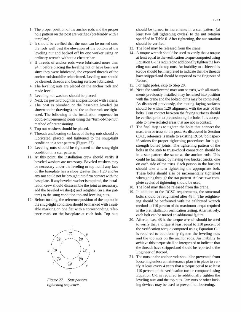
1. The proper position of the anchor rods and the properhole pattern on the post are verified (preferably with atemplate).
2. It should be verified that the nuts can be turned ontothe rods well past the elevation of the bottom of theleveling nut and backed off by one worker using anordinary wrench without a cheater bar.
3. If threads of anchor rods were lubricated more than 24 h before placing the leveling nut or have been wetsince they were lubricated, the exposed threads of theanchor rod should be relubricated. Leveling nuts shouldbe cleaned, threads and bearing surfaces lubricated.
4. The leveling nuts are placed on the anchor rods andmade level.
5. Leveling nut washers should be placed.6. Next, the post is brought in and positioned with a crane.7. The post is plumbed or the baseplate leveled (as
shown on the drawings) and the anchor rods are tight-ened. The following is the installation sequence fordouble-nut-moment joints using the “turn-of-the-nut”method of pretensioning.
8. Top nut washers should be placed.9. Threads and bearing surfaces of the top nuts should be
lubricated, placed, and tightened to the snug-tightcondition in a star pattern (Figure 27).
10. Leveling nuts should be tightened to the snug-tightcondition in a star pattern.
11. At this point, the installation crew should verify ifbeveled washers are necessary. Beveled washers maybe necessary under the leveling or top nut if any faceof the baseplate has a slope greater than 1:20 and/orany nut could not be brought into firm contact with thebaseplate. If any beveled washer is required, the instal-lation crew should disassemble the joint as necessary,add the beveled washer(s) and retighten (in a star pat-tern) to the snug condition top and leveling nuts.
12. Before turning, the reference position of the top nut inthe snug-tight condition should be marked with a suit-able marking on one flat with a corresponding refer-ence mark on the baseplate at each bolt. Top nuts
C-23
should be turned in increments in a star pattern (atleast two full tightening cycles) to the nut rotationspecified in Table 6. After tightening, the nut rotationshould be verified.
13. The load may be released from the crane.14. A torque wrench should be used to verify that a torque
at least equal to the verification torque computed usingEquation C-1 is required to additionally tighten the lev-eling nuts and the top nuts. An inability to achieve thistorque should be interpreted to indicate that the threadshave stripped and should be reported to the Engineer ofRecord.
15. For light poles, skip to Step 20.16. Next, the cantilevered mast arm or truss, with all attach-
ments previously installed, may be raised into positionwith the crane and the bolted joints may be completed.As discussed previously, the mating faying surfacesshould be within 1:20 alignment with the axis of thebolts. Firm contact between the faying surfaces shouldbe verified prior to pretensioning the bolts. It is accept-able to have isolated areas that are not in contact.
17. The final step is to tighten the bolts that connect themast arm or truss to the post. As discussed in SectionC.4.1, reference is made to existing RCSC bolt spec-ifications for proper tightening procedures for high-strength bolted joints. The tightening pattern of thebolts in the stub to truss-chord connection should bein a star pattern the same as the anchor rods. Thiscould be facilitated by having two bucket trucks, oneon each side of the truss. Each person in the bucketsshould take a turn tightening the appropriate bolt.These bolts should also be incrementally tightenedwhen going through the star pattern. At least two com-plete cycles of tightening should be used.
18. The load may then be released from the crane.19. In addition to the RCSC requirements, the structural
bolts should be retightened after 48 h. The retighten-ing should be performed with the calibrated wrenchmethod to 110 percent of the maximum torque requiredin the preinstallation verification testing. Alternatively,each bolt can be turned an additional 1⁄6 turn.
20. After at least 48 h, the torque wrench should be usedto verify that a torque at least equal to 110 percent ofthe verification torque computed using Equation C-1is required to additionally tighten the leveling nutsand the top nuts on the anchor rods. An inability toachieve this torque shall be interpreted to indicate thatthe threads have stripped and should be reported to theEngineer of Record.
21. The nuts on the anchor rods should be prevented fromloosening unless a maintenance plan is in place to ver-ify at least every 4 years that a torque equal to at least110 percent of the verification torque computed usingEquation C-1 is required to additionally tighten theleveling nuts and the top nuts. Jam nuts or other lock-ing devices may be used to prevent nut loosening.
Figure 27. Star patterntightening sequence.
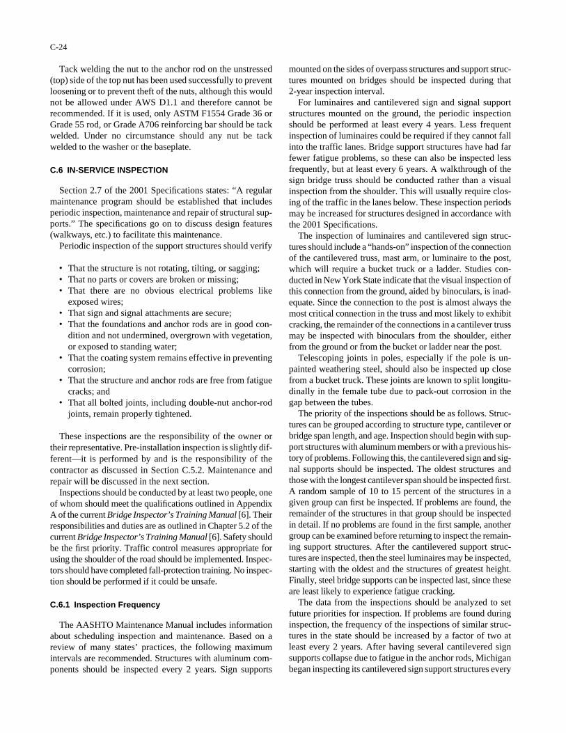
Tack welding the nut to the anchor rod on the unstressed(top) side of the top nut has been used successfully to preventloosening or to prevent theft of the nuts, although this wouldnot be allowed under AWS D1.1 and therefore cannot berecommended. If it is used, only ASTM F1554 Grade 36 orGrade 55 rod, or Grade A706 reinforcing bar should be tackwelded. Under no circumstance should any nut be tackwelded to the washer or the baseplate.
C.6 IN-SERVICE INSPECTION
Section 2.7 of the 2001 Specifications states: “A regularmaintenance program should be established that includesperiodic inspection, maintenance and repair of structural sup-ports.” The specifications go on to discuss design features(walkways, etc.) to facilitate this maintenance.
Periodic inspection of the support structures should verify
• That the structure is not rotating, tilting, or sagging;• That no parts or covers are broken or missing;• That there are no obvious electrical problems like
exposed wires;• That sign and signal attachments are secure;• That the foundations and anchor rods are in good con-
dition and not undermined, overgrown with vegetation,or exposed to standing water;
• That the coating system remains effective in preventingcorrosion;
• That the structure and anchor rods are free from fatiguecracks; and
• That all bolted joints, including double-nut anchor-rodjoints, remain properly tightened.
These inspections are the responsibility of the owner ortheir representative. Pre-installation inspection is slightly dif-ferent—it is performed by and is the responsibility of thecontractor as discussed in Section C.5.2. Maintenance andrepair will be discussed in the next section.
Inspections should be conducted by at least two people, oneof whom should meet the qualifications outlined in AppendixA of the current Bridge Inspector’s Training Manual [6]. Theirresponsibilities and duties are as outlined in Chapter 5.2 of thecurrent Bridge Inspector’s Training Manual [6]. Safety shouldbe the first priority. Traffic control measures appropriate forusing the shoulder of the road should be implemented. Inspec-tors should have completed fall-protection training. No inspec-tion should be performed if it could be unsafe.
C.6.1 Inspection Frequency
The AASHTO Maintenance Manual includes informationabout scheduling inspection and maintenance. Based on areview of many states’ practices, the following maximumintervals are recommended. Structures with aluminum com-ponents should be inspected every 2 years. Sign supports
C-24
mounted on the sides of overpass structures and support struc-tures mounted on bridges should be inspected during that 2-year inspection interval.
For luminaires and cantilevered sign and signal supportstructures mounted on the ground, the periodic inspectionshould be performed at least every 4 years. Less frequentinspection of luminaires could be required if they cannot fallinto the traffic lanes. Bridge support structures have had farfewer fatigue problems, so these can also be inspected lessfrequently, but at least every 6 years. A walkthrough of thesign bridge truss should be conducted rather than a visualinspection from the shoulder. This will usually require clos-ing of the traffic in the lanes below. These inspection periodsmay be increased for structures designed in accordance withthe 2001 Specifications.
The inspection of luminaires and cantilevered sign struc-tures should include a “hands-on” inspection of the connectionof the cantilevered truss, mast arm, or luminaire to the post,which will require a bucket truck or a ladder. Studies con-ducted in New York State indicate that the visual inspection ofthis connection from the ground, aided by binoculars, is inad-equate. Since the connection to the post is almost always themost critical connection in the truss and most likely to exhibitcracking, the remainder of the connections in a cantilever trussmay be inspected with binoculars from the shoulder, eitherfrom the ground or from the bucket or ladder near the post.
Telescoping joints in poles, especially if the pole is un-painted weathering steel, should also be inspected up closefrom a bucket truck. These joints are known to split longitu-dinally in the female tube due to pack-out corrosion in thegap between the tubes.
The priority of the inspections should be as follows. Struc-tures can be grouped according to structure type, cantilever orbridge span length, and age. Inspection should begin with sup-port structures with aluminum members or with a previous his-tory of problems. Following this, the cantilevered sign and sig-nal supports should be inspected. The oldest structures andthose with the longest cantilever span should be inspected first.A random sample of 10 to 15 percent of the structures in agiven group can first be inspected. If problems are found, theremainder of the structures in that group should be inspectedin detail. If no problems are found in the first sample, anothergroup can be examined before returning to inspect the remain-ing support structures. After the cantilevered support struc-tures are inspected, then the steel luminaires may be inspected,starting with the oldest and the structures of greatest height.Finally, steel bridge supports can be inspected last, since theseare least likely to experience fatigue cracking.
The data from the inspections should be analyzed to setfuture priorities for inspection. If problems are found duringinspection, the frequency of the inspections of similar struc-tures in the state should be increased by a factor of two atleast every 2 years. After having several cantilevered signsupports collapse due to fatigue in the anchor rods, Michiganbegan inspecting its cantilevered sign support structures every
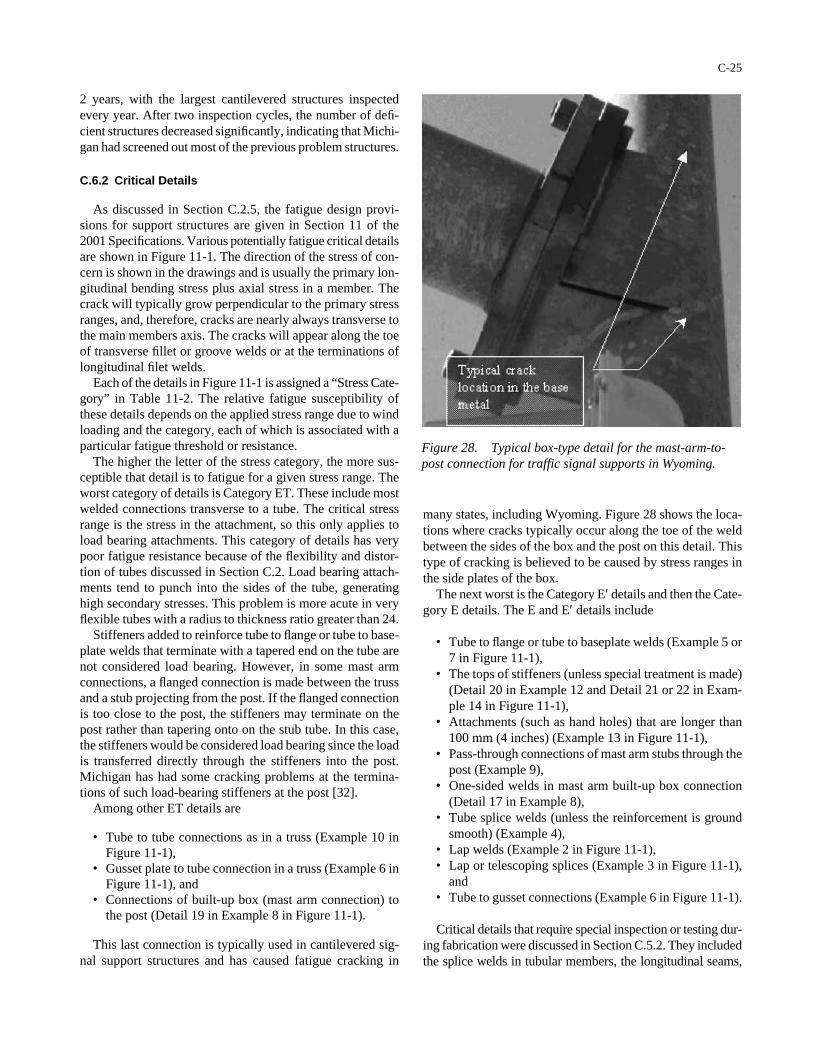
2 years, with the largest cantilevered structures inspectedevery year. After two inspection cycles, the number of defi-cient structures decreased significantly, indicating that Michi-gan had screened out most of the previous problem structures.
C.6.2 Critical Details
As discussed in Section C.2.5, the fatigue design provi-sions for support structures are given in Section 11 of the2001 Specifications. Various potentially fatigue critical detailsare shown in Figure 11-1. The direction of the stress of con-cern is shown in the drawings and is usually the primary lon-gitudinal bending stress plus axial stress in a member. Thecrack will typically grow perpendicular to the primary stressranges, and, therefore, cracks are nearly always transverse tothe main members axis. The cracks will appear along the toeof transverse fillet or groove welds or at the terminations oflongitudinal filet welds.
Each of the details in Figure 11-1 is assigned a “Stress Cate-gory” in Table 11-2. The relative fatigue susceptibility ofthese details depends on the applied stress range due to windloading and the category, each of which is associated with aparticular fatigue threshold or resistance.
The higher the letter of the stress category, the more sus-ceptible that detail is to fatigue for a given stress range. Theworst category of details is Category ET. These include mostwelded connections transverse to a tube. The critical stressrange is the stress in the attachment, so this only applies toload bearing attachments. This category of details has verypoor fatigue resistance because of the flexibility and distor-tion of tubes discussed in Section C.2. Load bearing attach-ments tend to punch into the sides of the tube, generatinghigh secondary stresses. This problem is more acute in veryflexible tubes with a radius to thickness ratio greater than 24.
Stiffeners added to reinforce tube to flange or tube to base-plate welds that terminate with a tapered end on the tube arenot considered load bearing. However, in some mast armconnections, a flanged connection is made between the trussand a stub projecting from the post. If the flanged connectionis too close to the post, the stiffeners may terminate on thepost rather than tapering onto on the stub tube. In this case,the stiffeners would be considered load bearing since the loadis transferred directly through the stiffeners into the post.Michigan has had some cracking problems at the termina-tions of such load-bearing stiffeners at the post [32].
Among other ET details are
• Tube to tube connections as in a truss (Example 10 inFigure 11-1),
• Gusset plate to tube connection in a truss (Example 6 inFigure 11-1), and
• Connections of built-up box (mast arm connection) tothe post (Detail 19 in Example 8 in Figure 11-1).
This last connection is typically used in cantilevered sig-nal support structures and has caused fatigue cracking in
C-25
many states, including Wyoming. Figure 28 shows the loca-tions where cracks typically occur along the toe of the weldbetween the sides of the box and the post on this detail. Thistype of cracking is believed to be caused by stress ranges inthe side plates of the box.
The next worst is the Category E′ details and then the Cate-gory E details. The E and E′ details include
• Tube to flange or tube to baseplate welds (Example 5 or7 in Figure 11-1),
• The tops of stiffeners (unless special treatment is made)(Detail 20 in Example 12 and Detail 21 or 22 in Exam-ple 14 in Figure 11-1),
• Attachments (such as hand holes) that are longer than100 mm (4 inches) (Example 13 in Figure 11-1),
• Pass-through connections of mast arm stubs through thepost (Example 9),
• One-sided welds in mast arm built-up box connection(Detail 17 in Example 8),
• Tube splice welds (unless the reinforcement is groundsmooth) (Example 4),
• Lap welds (Example 2 in Figure 11-1),• Lap or telescoping splices (Example 3 in Figure 11-1),
and• Tube to gusset connections (Example 6 in Figure 11-1).
Critical details that require special inspection or testing dur-ing fabrication were discussed in Section C.5.2. They includedthe splice welds in tubular members, the longitudinal seams,
Figure 28. Typical box-type detail for the mast-arm-to-post connection for traffic signal supports in Wyoming.
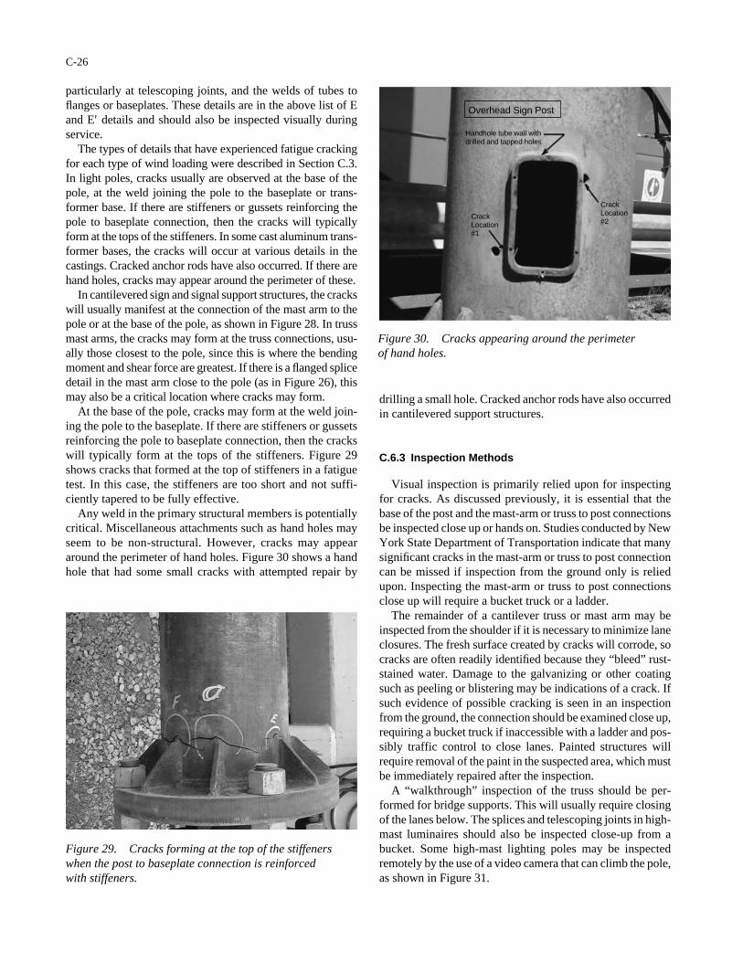
particularly at telescoping joints, and the welds of tubes toflanges or baseplates. These details are in the above list of Eand E′ details and should also be inspected visually duringservice.
The types of details that have experienced fatigue crackingfor each type of wind loading were described in Section C.3.In light poles, cracks usually are observed at the base of thepole, at the weld joining the pole to the baseplate or trans-former base. If there are stiffeners or gussets reinforcing thepole to baseplate connection, then the cracks will typicallyform at the tops of the stiffeners. In some cast aluminum trans-former bases, the cracks will occur at various details in thecastings. Cracked anchor rods have also occurred. If there arehand holes, cracks may appear around the perimeter of these.
In cantilevered sign and signal support structures, the crackswill usually manifest at the connection of the mast arm to thepole or at the base of the pole, as shown in Figure 28. In trussmast arms, the cracks may form at the truss connections, usu-ally those closest to the pole, since this is where the bendingmoment and shear force are greatest. If there is a flanged splicedetail in the mast arm close to the pole (as in Figure 26), thismay also be a critical location where cracks may form.
At the base of the pole, cracks may form at the weld join-ing the pole to the baseplate. If there are stiffeners or gussetsreinforcing the pole to baseplate connection, then the crackswill typically form at the tops of the stiffeners. Figure 29shows cracks that formed at the top of stiffeners in a fatiguetest. In this case, the stiffeners are too short and not suffi-ciently tapered to be fully effective.
Any weld in the primary structural members is potentiallycritical. Miscellaneous attachments such as hand holes mayseem to be non-structural. However, cracks may appeararound the perimeter of hand holes. Figure 30 shows a handhole that had some small cracks with attempted repair by
C-26
drilling a small hole. Cracked anchor rods have also occurredin cantilevered support structures.
C.6.3 Inspection Methods
Visual inspection is primarily relied upon for inspectingfor cracks. As discussed previously, it is essential that thebase of the post and the mast-arm or truss to post connectionsbe inspected close up or hands on. Studies conducted by NewYork State Department of Transportation indicate that manysignificant cracks in the mast-arm or truss to post connectioncan be missed if inspection from the ground only is reliedupon. Inspecting the mast-arm or truss to post connectionsclose up will require a bucket truck or a ladder.
The remainder of a cantilever truss or mast arm may beinspected from the shoulder if it is necessary to minimize laneclosures. The fresh surface created by cracks will corrode, socracks are often readily identified because they “bleed” rust-stained water. Damage to the galvanizing or other coatingsuch as peeling or blistering may be indications of a crack. Ifsuch evidence of possible cracking is seen in an inspectionfrom the ground, the connection should be examined close up,requiring a bucket truck if inaccessible with a ladder and pos-sibly traffic control to close lanes. Painted structures willrequire removal of the paint in the suspected area, which mustbe immediately repaired after the inspection.
A “walkthrough” inspection of the truss should be per-formed for bridge supports. This will usually require closingof the lanes below. The splices and telescoping joints in high-mast luminaires should also be inspected close-up from abucket. Some high-mast lighting poles may be inspectedremotely by the use of a video camera that can climb the pole,as shown in Figure 31.
Figure 29. Cracks forming at the top of the stiffenerswhen the post to baseplate connection is reinforced with stiffeners.
Overhead Sign Post
Handhole tube wall with drilled and tapped holes
Crack Location #2
Crack Location#1
Figure 30. Cracks appearing around the perimeter of hand holes.

If it is not clear if the visual indication is a crack or possi-bly just a crack in the coating or a scratch, the indication canbe further investigated using magnetic particle (MT) testingor dye-penetrant (PT) testing [7]. It is generally not worth-while to inspect areas using one of these methods unlessthere is a good reason to suspect there is a crack. Ultrasonictesting may be useful in some circumstances, but generallythe cracks will have penetrated through the thickness of themember and the MT and PT methods can find them moreeconomically.
As stated in Section C.2.5, fatigue cracks grow at an expo-nential rate, and 95 percent of the fatigue life is consumedwhile the crack size is less than a few millimeters long andnot detectable by any non-destructive test method includingultrasonic testing (UT). (In general, radiographic testing isnot useful for these support structures, as explained in Sec-tion C.5.2.) Thus, there is only a very small window of timewhen cracks will be large enough to be detected and stillsmall enough to not have yet caused fracture. The probabil-ity of conducting UT during this time and finding a crackbefore it is critical is extremely small and therefore typicallynot worth the cost. In addition, as discussed in Section C.5.2,UT is not reliable for a number of joints with backing ringsor partial penetration that will give significant indicationsand mask other defects.
On the other hand, ultrasonic testing may be useful incases where there is already reason to believe that thee maybe a small crack. For example, UT may be used for checkingother details on a structure when at least one detail hascracked. Also, when a crack is found on one structure, othernearby structures with similar details may be inspected withUT. Research performed by the Michigan Department ofTransportation determined that small cracks could be foundat the tips of load-bearing stiffeners terminated on the post[32]. The “Procedure for Ultrasonic Testing of Gusset Plates
C-27
on Cantilever Sign Supports” is available from theirconstruction and technology division. The procedure used a70-degree, 5-MHz miniature transducer. Most defects aredetected in the second leg during scanning. Typically, onlydeep cracks are found from the first leg.
If necessary, longitudinal wave UT is very effective for find-ing cracks in anchor rods. Research performed by the MichiganDepartment of Transportation determined that cracks as smallas 6 mm (0.25 inches) may be reliably detected.
The following is a summary of Michigan’s UT test proce-dure for anchor rods:
1. The technician must be certified to ASNT Level II onrecommended practice No. SNT-TC-1A.
2. Grind the ends of all anchor rods flat and perpendicu-lar to the long axis of the rod. Remove all scratches,galvanizing, or paint.
3. Calibrate the ultrasonic unit for straight beam probemethod using a 250-mm (10-inch) screen with a 25-mm(1-inch) diameter straight beam probe. The probe isplaced on a 1-inch calibration block, and the indica-tions on the screen are adjusted so that a reflection ispositioned at each 25-mm (1-inch) mark. Next, placethe probe on a 225-mm (9-inch) long test bar that has a3-mm (0.125-inch) deep saw cut at exactly 75 or 100 mm(3 or 4 inches) from the end in the threaded portion ofthe rod. Peak the back reflection from the 3-mm (0.125-inch) deep saw cut until the indication is at 60 percent or 80 percent of screen height. The dB reading is recordedto establish the “reference level.” The “scanning level” isset by 14 to 30 dB over the reference level.
4. Apply glycerin couplant to the ends of the bolts.5. Ultrasonically test the anchor rods in a circular motion.
There should be no indication between the zero depthlocation and the end of screen (250-mm or 10-inchdepth). Any indication is a possible flaw. Record thedepth of the indication and the amount of dB requiredto bring the indication to the reference level on thescreen. This is recorded as the “indication level.”
6. When complete, wipe off the couplant and spray thetops of the anchor rods with cold galvanizing or zincrich paint.
C.6.4 Inspection Checklist
The most important aspect of inspections is the record keep-ing. As discussed in Section C.5.2, a digital database should be established containing the records for each structure. Anyinspection should begin by reviewing the history of the struc-ture, starting with the design and fabrication documents. Thedesign and fabrication documents should include a set ofdesign drawings, shop drawings, the name and contact infor-mation for the designer/consultant of record, design calcula-tions explicitly showing the fatigue design as well as the tra-ditional allowable stress design for strength, the name and
Figure 31. Remote inspection of poles with self-climbingvideo camera.
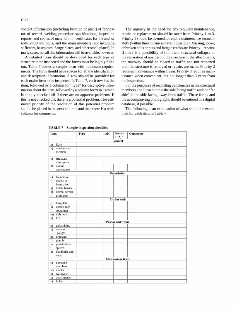
contact information (including location of plant) of fabrica-tor of record, welding procedure specifications, inspectionreports, and copies of material mill certificates for the anchorrods, structural bolts, and the main members (not includingstiffeners, baseplates, flange plates, and other small plates). Inmany cases, not all this information will be available, however.
A detailed form should be developed for each type ofstructure to be inspected and the forms must be legibly filledout. Table 7 shows a sample form with minimum require-ments. The form should have spaces for all the identificationand description information. A row should be provided foreach major item to be inspected. In Table 7, each row has theitem, followed by a column for “type” for descriptive infor-mation about the item, followed by a column for “OK” whichis simply checked off if there are no apparent problems. Ifthis is not checked off, there is a potential problem. The esti-mated priority of the resolution of this potential problemshould be placed in the next column, and then there is a widecolumn for comments.
C-28
The urgency in the need for any required maintenance,repair, or replacement should be rated from Priority 1 to 3.Priority 1 should be deemed to require maintenance immedi-ately (within three business days if possible). Missing, loose,or broken bolts or nuts and fatigue cracks are Priority 1 repairs.If there is a possibility of imminent structural collapse orthe separation of any part of the structure or the attachments,the roadway should be closed to traffic and not reopeneduntil the structure is removed or repairs are made. Priority 2requires maintenance within 1 year. Priority 3 requires main-tenance when convenient, but not longer than 3 years fromthe inspection.
For the purposes of recording deficiencies in the structuralmembers, the “near side” is the side facing traffic and the “farside” is the side facing away from traffic. These forms andthe accompanying photographs should be entered in a digitaldatabase, if possible.
The following is an explanation of what should be exam-ined for each item in Table 7.
Item Type OK Priority 1, 2, 3
Comments
General a) Date b) number and
location
c) structural description
d) overall appearance
Foundation e) foundation f) cracks in
foundation g) traffic barrier h) animal screen i) grout pad
Anchor rods j) baseplate k) anchor rods l) soundings m) tightness n) UT
Post or end frame o) galvanizing p) dents or
gouges q) drainage r) plumb s) post-to-base t) splices u) handholes and
caps Mast arm or truss
v) damaged members
w) cracks x) walkways y) attachments z) bolts
TABLE 7 Sample inspection checklist
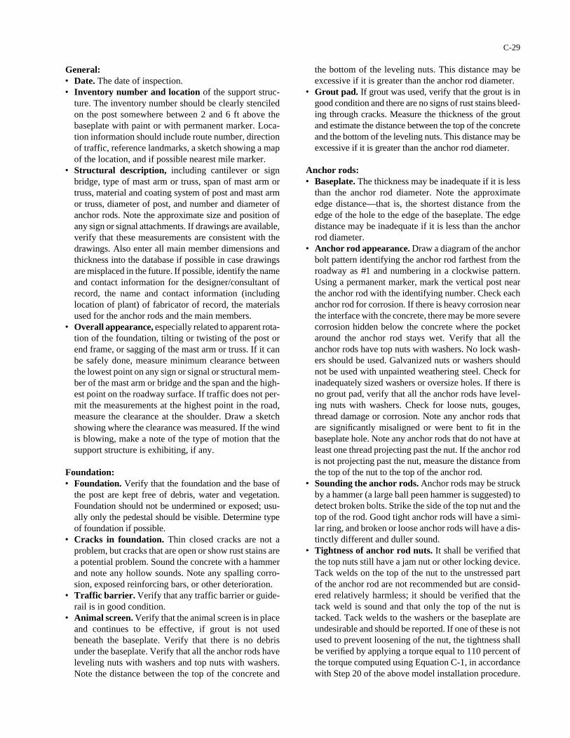
General:• Date. The date of inspection.• Inventory number and location of the support struc-
ture. The inventory number should be clearly stenciledon the post somewhere between 2 and 6 ft above thebaseplate with paint or with permanent marker. Loca-tion information should include route number, directionof traffic, reference landmarks, a sketch showing a mapof the location, and if possible nearest mile marker.
• Structural description, including cantilever or signbridge, type of mast arm or truss, span of mast arm ortruss, material and coating system of post and mast armor truss, diameter of post, and number and diameter ofanchor rods. Note the approximate size and position ofany sign or signal attachments. If drawings are available,verify that these measurements are consistent with thedrawings. Also enter all main member dimensions andthickness into the database if possible in case drawingsare misplaced in the future. If possible, identify the nameand contact information for the designer/consultant ofrecord, the name and contact information (includinglocation of plant) of fabricator of record, the materialsused for the anchor rods and the main members.
• Overall appearance, especially related to apparent rota-tion of the foundation, tilting or twisting of the post orend frame, or sagging of the mast arm or truss. If it canbe safely done, measure minimum clearance betweenthe lowest point on any sign or signal or structural mem-ber of the mast arm or bridge and the span and the high-est point on the roadway surface. If traffic does not per-mit the measurements at the highest point in the road,measure the clearance at the shoulder. Draw a sketchshowing where the clearance was measured. If the windis blowing, make a note of the type of motion that thesupport structure is exhibiting, if any.
Foundation:• Foundation. Verify that the foundation and the base of
the post are kept free of debris, water and vegetation.Foundation should not be undermined or exposed; usu-ally only the pedestal should be visible. Determine typeof foundation if possible.
• Cracks in foundation. Thin closed cracks are not aproblem, but cracks that are open or show rust stains area potential problem. Sound the concrete with a hammerand note any hollow sounds. Note any spalling corro-sion, exposed reinforcing bars, or other deterioration.
• Traffic barrier. Verify that any traffic barrier or guide-rail is in good condition.
• Animal screen. Verify that the animal screen is in placeand continues to be effective, if grout is not usedbeneath the baseplate. Verify that there is no debrisunder the baseplate. Verify that all the anchor rods haveleveling nuts with washers and top nuts with washers.Note the distance between the top of the concrete and
C-29
the bottom of the leveling nuts. This distance may beexcessive if it is greater than the anchor rod diameter.
• Grout pad. If grout was used, verify that the grout is ingood condition and there are no signs of rust stains bleed-ing through cracks. Measure the thickness of the groutand estimate the distance between the top of the concreteand the bottom of the leveling nuts. This distance may beexcessive if it is greater than the anchor rod diameter.
Anchor rods:• Baseplate. The thickness may be inadequate if it is less
than the anchor rod diameter. Note the approximateedge distance—that is, the shortest distance from theedge of the hole to the edge of the baseplate. The edgedistance may be inadequate if it is less than the anchorrod diameter.
• Anchor rod appearance. Draw a diagram of the anchorbolt pattern identifying the anchor rod farthest from theroadway as #1 and numbering in a clockwise pattern.Using a permanent marker, mark the vertical post nearthe anchor rod with the identifying number. Check eachanchor rod for corrosion. If there is heavy corrosion nearthe interface with the concrete, there may be more severecorrosion hidden below the concrete where the pocketaround the anchor rod stays wet. Verify that all theanchor rods have top nuts with washers. No lock wash-ers should be used. Galvanized nuts or washers shouldnot be used with unpainted weathering steel. Check forinadequately sized washers or oversize holes. If there isno grout pad, verify that all the anchor rods have level-ing nuts with washers. Check for loose nuts, gouges,thread damage or corrosion. Note any anchor rods thatare significantly misaligned or were bent to fit in thebaseplate hole. Note any anchor rods that do not have atleast one thread projecting past the nut. If the anchor rodis not projecting past the nut, measure the distance fromthe top of the nut to the top of the anchor rod.
• Sounding the anchor rods. Anchor rods may be struckby a hammer (a large ball peen hammer is suggested) todetect broken bolts. Strike the side of the top nut and thetop of the rod. Good tight anchor rods will have a simi-lar ring, and broken or loose anchor rods will have a dis-tinctly different and duller sound.
• Tightness of anchor rod nuts. It shall be verified thatthe top nuts still have a jam nut or other locking device.Tack welds on the top of the nut to the unstressed partof the anchor rod are not recommended but are consid-ered relatively harmless; it should be verified that thetack weld is sound and that only the top of the nut istacked. Tack welds to the washers or the baseplate areundesirable and should be reported. If one of these is notused to prevent loosening of the nut, the tightness shallbe verified by applying a torque equal to 110 percent ofthe torque computed using Equation C-1, in accordancewith Step 20 of the above model installation procedure.
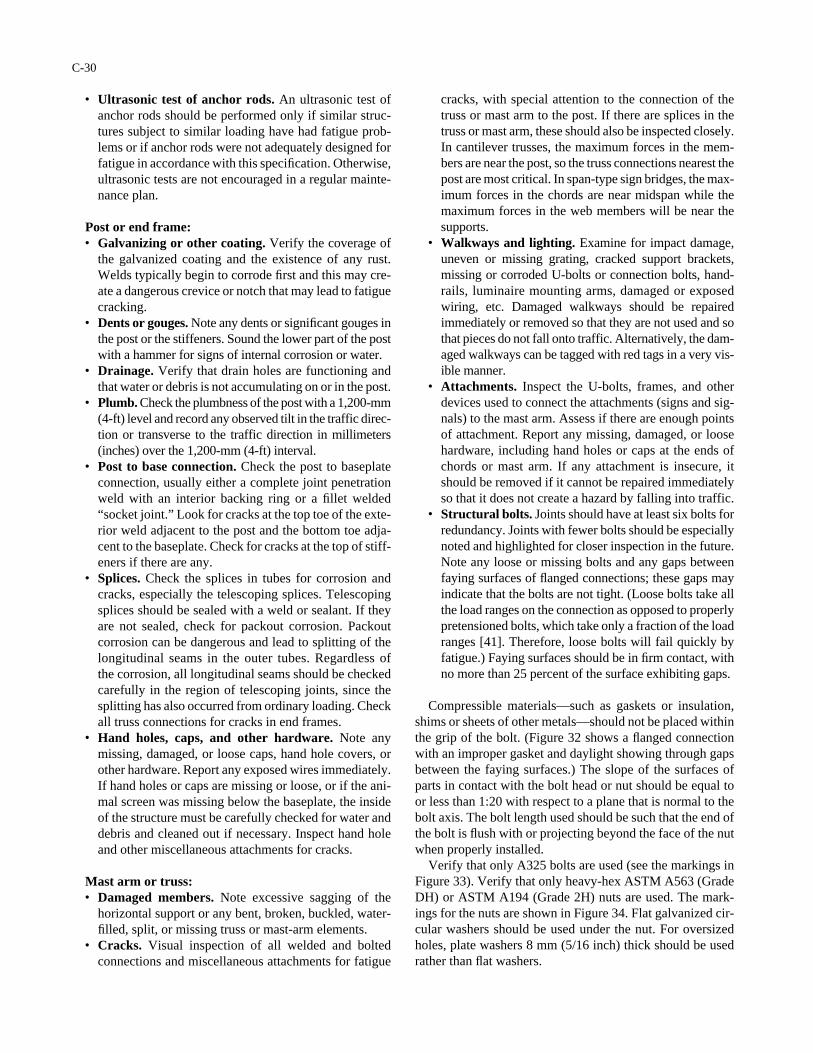
• Ultrasonic test of anchor rods. An ultrasonic test ofanchor rods should be performed only if similar struc-tures subject to similar loading have had fatigue prob-lems or if anchor rods were not adequately designed forfatigue in accordance with this specification. Otherwise,ultrasonic tests are not encouraged in a regular mainte-nance plan.
Post or end frame:• Galvanizing or other coating. Verify the coverage of
the galvanized coating and the existence of any rust.Welds typically begin to corrode first and this may cre-ate a dangerous crevice or notch that may lead to fatiguecracking.
• Dents or gouges. Note any dents or significant gouges inthe post or the stiffeners. Sound the lower part of the postwith a hammer for signs of internal corrosion or water.
• Drainage. Verify that drain holes are functioning andthat water or debris is not accumulating on or in the post.
• Plumb. Check the plumbness of the post with a 1,200-mm(4-ft) level and record any observed tilt in the traffic direc-tion or transverse to the traffic direction in millimeters(inches) over the 1,200-mm (4-ft) interval.
• Post to base connection. Check the post to baseplateconnection, usually either a complete joint penetrationweld with an interior backing ring or a fillet welded“socket joint.” Look for cracks at the top toe of the exte-rior weld adjacent to the post and the bottom toe adja-cent to the baseplate. Check for cracks at the top of stiff-eners if there are any.
• Splices. Check the splices in tubes for corrosion andcracks, especially the telescoping splices. Telescopingsplices should be sealed with a weld or sealant. If theyare not sealed, check for packout corrosion. Packoutcorrosion can be dangerous and lead to splitting of thelongitudinal seams in the outer tubes. Regardless ofthe corrosion, all longitudinal seams should be checkedcarefully in the region of telescoping joints, since thesplitting has also occurred from ordinary loading. Checkall truss connections for cracks in end frames.
• Hand holes, caps, and other hardware. Note anymissing, damaged, or loose caps, hand hole covers, orother hardware. Report any exposed wires immediately.If hand holes or caps are missing or loose, or if the ani-mal screen was missing below the baseplate, the insideof the structure must be carefully checked for water anddebris and cleaned out if necessary. Inspect hand holeand other miscellaneous attachments for cracks.
Mast arm or truss:• Damaged members. Note excessive sagging of the
horizontal support or any bent, broken, buckled, water-filled, split, or missing truss or mast-arm elements.
• Cracks. Visual inspection of all welded and boltedconnections and miscellaneous attachments for fatigue
C-30
cracks, with special attention to the connection of thetruss or mast arm to the post. If there are splices in thetruss or mast arm, these should also be inspected closely.In cantilever trusses, the maximum forces in the mem-bers are near the post, so the truss connections nearest thepost are most critical. In span-type sign bridges, the max-imum forces in the chords are near midspan while themaximum forces in the web members will be near thesupports.
• Walkways and lighting. Examine for impact damage,uneven or missing grating, cracked support brackets,missing or corroded U-bolts or connection bolts, hand-rails, luminaire mounting arms, damaged or exposedwiring, etc. Damaged walkways should be repairedimmediately or removed so that they are not used and sothat pieces do not fall onto traffic. Alternatively, the dam-aged walkways can be tagged with red tags in a very vis-ible manner.
• Attachments. Inspect the U-bolts, frames, and otherdevices used to connect the attachments (signs and sig-nals) to the mast arm. Assess if there are enough pointsof attachment. Report any missing, damaged, or loosehardware, including hand holes or caps at the ends ofchords or mast arm. If any attachment is insecure, itshould be removed if it cannot be repaired immediatelyso that it does not create a hazard by falling into traffic.
• Structural bolts. Joints should have at least six bolts forredundancy. Joints with fewer bolts should be especiallynoted and highlighted for closer inspection in the future.Note any loose or missing bolts and any gaps betweenfaying surfaces of flanged connections; these gaps mayindicate that the bolts are not tight. (Loose bolts take allthe load ranges on the connection as opposed to properlypretensioned bolts, which take only a fraction of the loadranges [41]. Therefore, loose bolts will fail quickly byfatigue.) Faying surfaces should be in firm contact, withno more than 25 percent of the surface exhibiting gaps.
Compressible materials—such as gaskets or insulation,shims or sheets of other metals—should not be placed withinthe grip of the bolt. (Figure 32 shows a flanged connectionwith an improper gasket and daylight showing through gapsbetween the faying surfaces.) The slope of the surfaces ofparts in contact with the bolt head or nut should be equal toor less than 1:20 with respect to a plane that is normal to thebolt axis. The bolt length used should be such that the end ofthe bolt is flush with or projecting beyond the face of the nutwhen properly installed.
Verify that only A325 bolts are used (see the markings inFigure 33). Verify that only heavy-hex ASTM A563 (GradeDH) or ASTM A194 (Grade 2H) nuts are used. The mark-ings for the nuts are shown in Figure 34. Flat galvanized cir-cular washers should be used under the nut. For oversizedholes, plate washers 8 mm (5/16 inch) thick should be usedrather than flat washers.
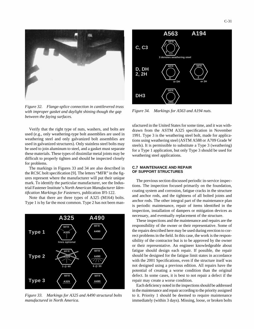
A325 A490
Type 1
Type 2
Type 3
MFR
MFR
MFR
MFR
MFR
MFR
A325
A325
A325
A490
A490
A490
3 @ 60
lines optional
6 @ 30
A563 A194
C, C3
D, DH2, 2H
DH3
MFR
MFR
MFR
MFR
3 denotes weathering steel
D 2
DH3
or DH or 2H
3
Verify that the right type of nuts, washers, and bolts areused (e.g., only weathering-type bolt assemblies are used inweathering steel and only galvanized bolt assemblies areused in galvanized structures). Only stainless steel bolts maybe used to join aluminum to steel, and a gasket must separatethese materials. These types of dissimilar metal joints may bedifficult to properly tighten and should be inspected closelyfor problems.
The markings in Figures 33 and 34 are also described inthe RCSC bolt specification [9]. The letters “MFR” in the fig-ures represent where the manufacturer will put their uniquemark. To identify the particular manufacturer, see the Indus-trial Fastener Institute’s North American Manufacturer Iden-tification Markings for Fasteners, publication IFI-122.
Note that there are three types of A325 (M164) bolts.Type 1 is by far the most common. Type 2 has not been man-
C-31
ufactured in the United States for some time, and it was with-drawn from the ASTM A325 specification in November1991. Type 3 is the weathering steel bolt, made for applica-tions using weathering steel (ASTM A588 or A709 Grade Wsteels). It is permissible to substitute a Type 3 (weathering)for a Type 1 application, but only Type 3 should be used forweathering steel applications.
C.7 MAINTENANCE AND REPAIR OF SUPPORT STRUCTURES
The previous section discussed periodic in-service inspec-tions. The inspection focused primarily on the foundation,coating system and corrosion, fatigue cracks in the structureand anchor rods, and the tightness of all bolted joints andanchor rods. The other integral part of the maintenance planis periodic maintenance, repair of items identified in theinspection, installation of dampers or mitigation devices asnecessary, and eventually replacement of the structure.
These inspections and the maintenance and repairs are theresponsibility of the owner or their representative. Some ofthe repairs described here may be used during erection to cor-rect problems in the field. In this case, the work is the respon-sibility of the contractor but is to be approved by the owneror their representative. An engineer knowledgeable aboutfatigue should design each repair. If possible, the repairshould be designed for the fatigue limit states in accordancewith the 2001 Specifications, even if the structure itself wasnot designed using a previous edition. All repairs have thepotential of creating a worse condition than the originaldefect. In some cases, it is best to not repair a defect if therepair may create a worse condition.
Each deficiency noted in the inspections should be addressedin the maintenance and repair according to the priority assignedto it. Priority 1 should be deemed to require maintenanceimmediately (within 3 days). Missing, loose, or broken bolts
Figure 32. Flange-splice connection in cantilevered trusswith improper gasket and daylight shining though the gapbetween the faying surfaces.
Figure 33. Markings for A325 and A490 structural boltsmanufactured in North America.
Figure 34. Markings for A563 and A194 nuts.

or nuts and fatigue cracks are Priority 1 repairs. A structurewhich is reported to be or observed vibrating excessively forlong continuous periods should be immediately fitted with a damper or mitigation device appropriate for the type ofwind loading, as explained in Section C.3, especially if it issuspected to be galloping or vortex shedding. If there is apossibility of imminent structural collapse or separation ofany part of the structure or the attachments, the roadwayshould be closed to traffic and not reopened until thestructure is removed or repairs are made. Priority 2 requiresmaintenance within 1 year. Priority 3 requires maintenancewhen convenient, but not longer than 3 years from theinspection.
Routine maintenance and minor repairs such as touchup ofthe coating system can be noted briefly. However, a detailedrecord of all significant repairs should be kept in the files orin the digital database. The repair record should include someof the same preliminary information on the inspection forms:
• The date of the repair,• Inventory number and location of the support structure,
and• Structural description.
The record of the repairs should include a complete descrip-tion and drawing of the original part of the structure beingrepaired, the type of defect, the repair, the materials of theoriginal part of the structure and any components added inthe repair, and weld procedure specifications for any repairwelding. Typically, repairs must be inspected closely aftercompletion and periodically in the future.
C.7.1 Routine Maintenance
Some maintenance is easy to perform and should be per-formed at the time of the inspection. For example, touchupof the galvanizing can be accomplished by grinding awayany rust to bright metal and painting with zinc-rich paint orcold galvanizing (ZRC). Similarly, for painted structures,grinding may be performed to inspect more closely or toremove rust, and these areas should be repainted immedi-ately after inspection.
Small holes may also be drilled at the time of inspection tolook for and drain any standing water. Holes up to 13 mm indiameter may be drilled without concern for the strength orfatigue resistance of the structure. Repairs involving largerholes must be evaluated on a case-by-case basis by an engineerand planned in advance. If tubes fill with water, they should bedrained by drilling a 13-mm (0.5-inch) diameter hole near thebottom of the tube. If the water remains undrained, it can accel-erate corrosion or rupture the tube if it freezes. Also, smallholes should be drilled immediately at the tips of fatigue cracksas a temporary measure to arrest the crack.
Some repairs may be performed at the time of inspection.For example, grout can be removed from under the baseplate
C-32
for double-nut-moment joints so that the anchor rods and lev-eling nuts can be inspected, especially if the anchor rodssound unusual. Replacement of missing or broken animalscreens, hand hole covers, post caps, and other hardware maybe performed at the time of inspection. Replacement of miss-ing structural bolts, replacement of anchor rod nuts (thesehave been stolen in some locations), and retightening ofanchor rods and structural bolts may also be done at the timeof inspection. The inspection team should carry the necessarytools and inventory of parts and fasteners.
In addition, some regular maintenance not associated withparticular deficiencies should be performed at the time ofinspections. For example, vegetation should be cut backaway from the structure and soil and debris washed off thestructure.
C.7.2 Repairs Related to the Foundation
The soil should be no closer than 100 mm (4 inches) to thetop of the concrete pedestal. Poor drainage, erosion, orundermining should be corrected by regrading and compact-ing the fill.
If the clearance was found to be inadequate or if the postis out-of-plumb, the cause should be determined (e.g., it maybe due to pavement overlays or settlement or rotation of thefoundation). It may be possible to raise or relevel the struc-ture on the anchor rods if there is enough projecting abovethe top nuts. Any increase in bending should be calculatedand the design reevaluated if the bottom of the leveling nutsis raised above the top of concrete by more than one anchorrod diameter. If the structure cannot be raised or releveled onthe anchor rods, it is probably necessary to construct a newfoundation and place the structure on the new foundation.
If the concrete foundation is excessively cracked, cor-roded, or otherwise deteriorated, it may be possible to chipaway the deteriorated concrete and repair the area using ordi-nary concrete or special mixes, including additives, espe-cially for repair. If the deterioration is severe, it is probablynecessary to construct a new foundation and place the struc-ture on the new foundation.
Damage to the barriers or guiderail should be repairedusing established procedures.
If there is no animal screen, one can be made from stain-less steel screen with an opening not larger than 7 mm. Thescreen may be secured using stainless steel tension straps. Ifthere is no screen and the access to the pole is open (no grouteither) then there have probably been animals inside the post.Every effort should be made to clean out any debris. Specialattention should be made to inspecting the electrical wires,which may have been chewed.
If grout is under the baseplate and rust is found or if level-ing nuts are suspected to be loose, the grout should be removedfor more detailed investigation. Often, wire brushing anddrying of the exposed rusted surfaces may be enough toreduce further corrosion, but the need for additional repairs
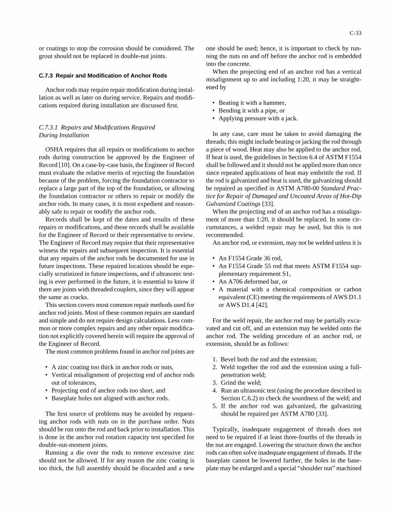
or coatings to stop the corrosion should be considered. Thegrout should not be replaced in double-nut joints.
C.7.3 Repair and Modification of Anchor Rods
Anchor rods may require repair modification during instal-lation as well as later on during service. Repairs and modifi-cations required during installation are discussed first.
C.7.3.1 Repairs and Modifications RequiredDuring Installation
OSHA requires that all repairs or modifications to anchorrods during construction be approved by the Engineer ofRecord [10]. On a case-by-case basis, the Engineer of Recordmust evaluate the relative merits of rejecting the foundationbecause of the problem, forcing the foundation contractor toreplace a large part of the top of the foundation, or allowingthe foundation contractor or others to repair or modify theanchor rods. In many cases, it is most expedient and reason-ably safe to repair or modify the anchor rods.
Records shall be kept of the dates and results of theserepairs or modifications, and these records shall be availablefor the Engineer of Record or their representative to review.The Engineer of Record may require that their representativewitness the repairs and subsequent inspection. It is essentialthat any repairs of the anchor rods be documented for use infuture inspections. These repaired locations should be espe-cially scrutinized in future inspections, and if ultrasonic test-ing is ever performed in the future, it is essential to know ifthere are joints with threaded couplers, since they will appearthe same as cracks.
This section covers most common repair methods used foranchor rod joints. Most of these common repairs are standardand simple and do not require design calculations. Less com-mon or more complex repairs and any other repair modifica-tion not explicitly covered herein will require the approval ofthe Engineer of Record.
The most common problems found in anchor rod joints are
• A zinc coating too thick in anchor rods or nuts,• Vertical misalignment of projecting end of anchor rods
out of tolerances,• Projecting end of anchor rods too short, and• Baseplate holes not aligned with anchor rods.
The first source of problems may be avoided by request-ing anchor rods with nuts on in the purchase order. Nutsshould be run onto the rod and back prior to installation. Thisis done in the anchor rod rotation capacity test specified fordouble-nut-moment joints.
Running a die over the rods to remove excessive zincshould not be allowed. If for any reason the zinc coating istoo thick, the full assembly should be discarded and a new
C-33
one should be used; hence, it is important to check by run-ning the nuts on and off before the anchor rod is embeddedinto the concrete.
When the projecting end of an anchor rod has a verticalmisalignment up to and including 1:20, it may be straight-ened by
• Beating it with a hammer,• Bending it with a pipe, or• Applying pressure with a jack.
In any case, care must be taken to avoid damaging thethreads; this might include beating or jacking the rod througha piece of wood. Heat may also be applied to the anchor rod.If heat is used, the guidelines in Section 6.4 of ASTM F1554shall be followed and it should not be applied more than oncesince repeated applications of heat may embrittle the rod. Ifthe rod is galvanized and heat is used, the galvanizing shouldbe repaired as specified in ASTM A780-00 Standard Prac-tice for Repair of Damaged and Uncoated Areas of Hot-DipGalvanized Coatings [33].
When the projecting end of an anchor rod has a misalign-ment of more than 1:20, it should be replaced. In some cir-cumstances, a welded repair may be used, but this is notrecommended.
An anchor rod, or extension, may not be welded unless it is
• An F1554 Grade 36 rod,• An F1554 Grade 55 rod that meets ASTM F1554 sup-
plementary requirement S1,• An A706 deformed bar, or• A material with a chemical composition or carbon
equivalent (CE) meeting the requirements of AWS D1.1or AWS D1.4 [42].
For the weld repair, the anchor rod may be partially exca-vated and cut off, and an extension may be welded onto theanchor rod. The welding procedure of an anchor rod, orextension, should be as follows:
1. Bevel both the rod and the extension;2. Weld together the rod and the extension using a full-
penetration weld;3. Grind the weld;4. Run an ultrasonic test (using the procedure described in
Section C.6.2) to check the soundness of the weld; and5. If the anchor rod was galvanized, the galvanizing
should be repaired per ASTM A780 [33].
Typically, inadequate engagement of threads does notneed to be repaired if at least three-fourths of the threads inthe nut are engaged. Lowering the structure down the anchorrods can often solve inadequate engagement of threads. If thebaseplate cannot be lowered further, the holes in the base-plate may be enlarged and a special “shoulder nut” machined
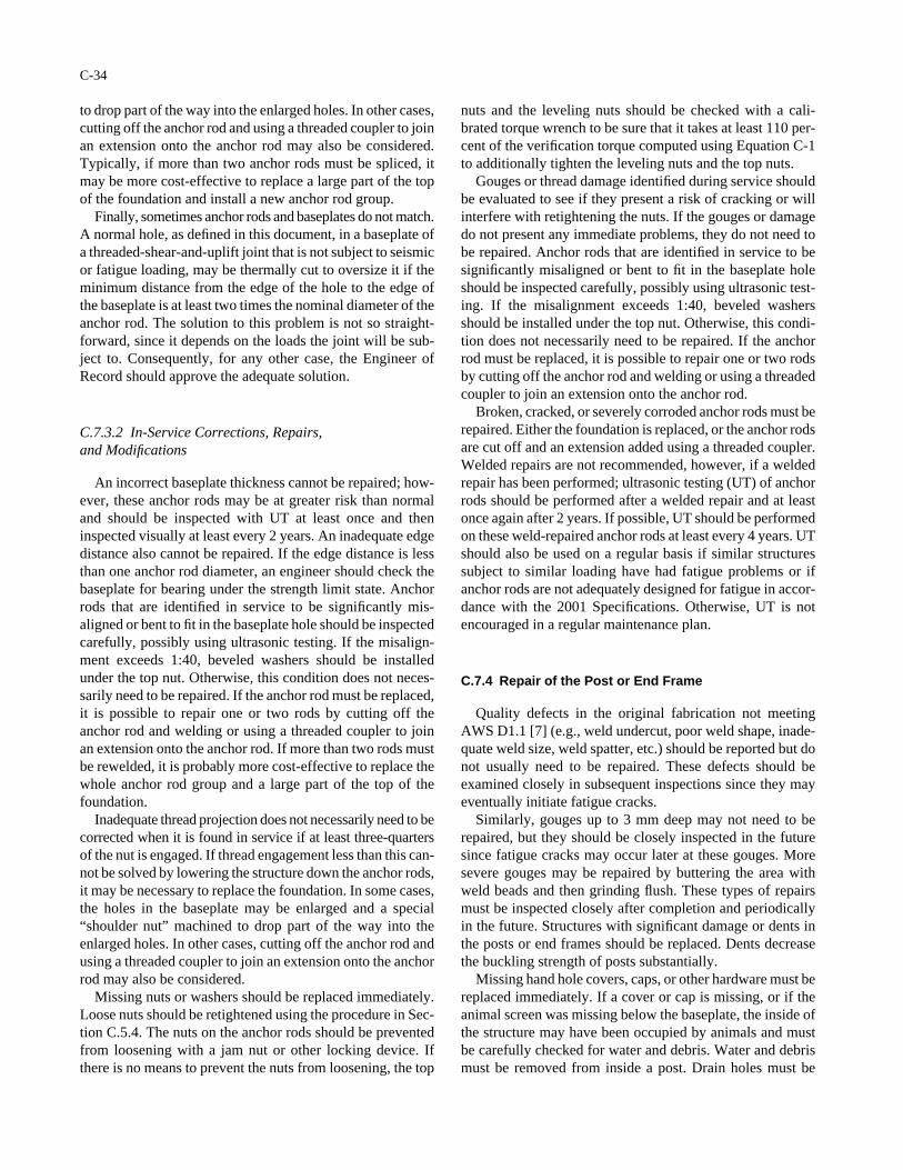
to drop part of the way into the enlarged holes. In other cases,cutting off the anchor rod and using a threaded coupler to joinan extension onto the anchor rod may also be considered.Typically, if more than two anchor rods must be spliced, itmay be more cost-effective to replace a large part of the topof the foundation and install a new anchor rod group.
Finally, sometimes anchor rods and baseplates do not match.A normal hole, as defined in this document, in a baseplate ofa threaded-shear-and-uplift joint that is not subject to seismicor fatigue loading, may be thermally cut to oversize it if theminimum distance from the edge of the hole to the edge ofthe baseplate is at least two times the nominal diameter of theanchor rod. The solution to this problem is not so straight-forward, since it depends on the loads the joint will be sub-ject to. Consequently, for any other case, the Engineer ofRecord should approve the adequate solution.
C.7.3.2 In-Service Corrections, Repairs, and Modifications
An incorrect baseplate thickness cannot be repaired; how-ever, these anchor rods may be at greater risk than normaland should be inspected with UT at least once and theninspected visually at least every 2 years. An inadequate edgedistance also cannot be repaired. If the edge distance is lessthan one anchor rod diameter, an engineer should check thebaseplate for bearing under the strength limit state. Anchorrods that are identified in service to be significantly mis-aligned or bent to fit in the baseplate hole should be inspectedcarefully, possibly using ultrasonic testing. If the misalign-ment exceeds 1:40, beveled washers should be installedunder the top nut. Otherwise, this condition does not neces-sarily need to be repaired. If the anchor rod must be replaced,it is possible to repair one or two rods by cutting off theanchor rod and welding or using a threaded coupler to joinan extension onto the anchor rod. If more than two rods mustbe rewelded, it is probably more cost-effective to replace thewhole anchor rod group and a large part of the top of thefoundation.
Inadequate thread projection does not necessarily need to becorrected when it is found in service if at least three-quartersof the nut is engaged. If thread engagement less than this can-not be solved by lowering the structure down the anchor rods,it may be necessary to replace the foundation. In some cases,the holes in the baseplate may be enlarged and a special“shoulder nut” machined to drop part of the way into theenlarged holes. In other cases, cutting off the anchor rod andusing a threaded coupler to join an extension onto the anchorrod may also be considered.
Missing nuts or washers should be replaced immediately.Loose nuts should be retightened using the procedure in Sec-tion C.5.4. The nuts on the anchor rods should be preventedfrom loosening with a jam nut or other locking device. Ifthere is no means to prevent the nuts from loosening, the top
C-34
nuts and the leveling nuts should be checked with a cali-brated torque wrench to be sure that it takes at least 110 per-cent of the verification torque computed using Equation C-1to additionally tighten the leveling nuts and the top nuts.
Gouges or thread damage identified during service shouldbe evaluated to see if they present a risk of cracking or willinterfere with retightening the nuts. If the gouges or damagedo not present any immediate problems, they do not need tobe repaired. Anchor rods that are identified in service to besignificantly misaligned or bent to fit in the baseplate holeshould be inspected carefully, possibly using ultrasonic test-ing. If the misalignment exceeds 1:40, beveled washersshould be installed under the top nut. Otherwise, this condi-tion does not necessarily need to be repaired. If the anchorrod must be replaced, it is possible to repair one or two rodsby cutting off the anchor rod and welding or using a threadedcoupler to join an extension onto the anchor rod.
Broken, cracked, or severely corroded anchor rods must berepaired. Either the foundation is replaced, or the anchor rodsare cut off and an extension added using a threaded coupler.Welded repairs are not recommended, however, if a weldedrepair has been performed; ultrasonic testing (UT) of anchorrods should be performed after a welded repair and at leastonce again after 2 years. If possible, UT should be performedon these weld-repaired anchor rods at least every 4 years. UTshould also be used on a regular basis if similar structuressubject to similar loading have had fatigue problems or ifanchor rods are not adequately designed for fatigue in accor-dance with the 2001 Specifications. Otherwise, UT is notencouraged in a regular maintenance plan.
C.7.4 Repair of the Post or End Frame
Quality defects in the original fabrication not meetingAWS D1.1 [7] (e.g., weld undercut, poor weld shape, inade-quate weld size, weld spatter, etc.) should be reported but donot usually need to be repaired. These defects should beexamined closely in subsequent inspections since they mayeventually initiate fatigue cracks.
Similarly, gouges up to 3 mm deep may not need to berepaired, but they should be closely inspected in the futuresince fatigue cracks may occur later at these gouges. Moresevere gouges may be repaired by buttering the area withweld beads and then grinding flush. These types of repairsmust be inspected closely after completion and periodicallyin the future. Structures with significant damage or dents inthe posts or end frames should be replaced. Dents decreasethe buckling strength of posts substantially.
Missing hand hole covers, caps, or other hardware must bereplaced immediately. If a cover or cap is missing, or if theanimal screen was missing below the baseplate, the inside ofthe structure may have been occupied by animals and mustbe carefully checked for water and debris. Water and debrismust be removed from inside a post. Drain holes must be
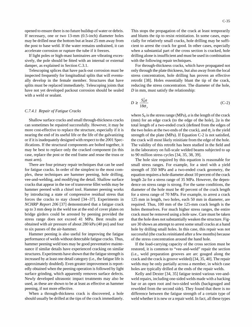
opened to ensure there is no future buildup of water or debris.If necessary, one or two 13-mm (0.5-inch) diameter holesmay be drilled near the bottom but at least 25 mm away fromthe post to base weld. If the water remains undrained, it canaccelerate corrosion or rupture the tube if it freezes.
If light poles or high-mast luminaires are vibrating exces-sively, the pole should be fitted with an internal or externaldamper, as explained in Section C.3.1.
Telescoping splices that have pack-out corrosion must beinspected frequently for longitudinal splits that will eventu-ally develop in the female member. Structures that havesplits must be replaced immediately. Telescoping joints thathave not yet developed packout corrosion should be sealedwith a weld or sealant.
C.7.4.1 Repair of Fatigue Cracks
Shallow surface cracks and small through-thickness crackscan sometimes be repaired successfully. However, it may bemore cost-effective to replace the structure, especially if it isnearing the end of its useful life or the life of the galvanizingor if it is inadequately designed with respect to the 2001 Spec-ifications. If the structural components are bolted together, itmay be best to replace only the cracked component (in thiscase, replace the post or the end frame and reuse the truss ormast arm).
There are four primary repair techniques that can be usedfor fatigue cracks. In order of the simplest to the most com-plex, these techniques are hammer peening, hole drilling,vee-and-welding, and modifying the detail. Shallow surfacecracks that appear in the toe of transverse fillet welds may behammer peened with a chisel tool. Hammer peening worksby introducing a state of compressive residual stress thatforces the cracks to stay closed [34–37]. Experiments inNCHRP Report 206 [37] demonstrated that a fatigue crackup to 3 mm deep in the weld toe at the end of cover plates onbridge girders could be arrested by peening provided thestress range does not exceed 41 MPa. Best results areobtained with air pressure of about 280 kPa (40 psi) and fourto six passes of the air-hammer.
Hammer peening is also useful for improving the fatigueperformance of welds without detectable fatigue cracks. Thus,hammer peening weld toes may be good preventative mainte-nance if similar details have experienced cracking on similarstructures. Experiments have shown that the fatigue strength isincreased by at least one detail category (i.e., the fatigue life isapproximately doubled). Even greater improvement is report-edly obtained when the peening operation is followed by lightsurface grinding, which apparently removes surface defects.Newly developed ultrasonic impact treatments may also beused, as these are shown to be at least as effective as hammerpeening, if not more effective.
When a through-thickness crack is discovered, a holeshould usually be drilled at the tips of the crack immediately.
C-35
This stops the propagation of the crack at least temporarilyand blunts the tip to resist reinitiation. In some cases, espe-cially for relatively small cracks, hole drilling may be suffi-cient to arrest the crack for good. In other cases, especiallywhen a substantial part of the cross section is cracked, holedrilling alone is insufficient and must be used in combinationwith the following repair techniques.
For through-thickness cracks, which have propagated notonly through the plate thickness, but also away from the localstress concentration, hole drilling has proven an effectiveretrofit [38]. Holes essentially blunt the tip of the crack,reducing the stress concentration. The diameter of the hole,D in mm, must satisfy the relationship:
where SR is the stress range (MPa), a is the length of the crack(mm) for an edge crack (to the edge of the hole), 2a is thetotal length of a two-ended crack (defined from the edges ofthe two holes at the two ends of the crack), and σy is the yieldstrength of the plate (MPa). If Equation C-2 is not satisfied,the crack will most likely reinitiate from the edge of the hole.The validity of this retrofit has been studied in the field andin the laboratory on full-scale welded beams subjected to upto 90 million stress cycles [34, 35, 38, 39].
The hole size required by this equation is reasonable forsmall stress ranges. For example, for a steel with a yieldstrength of 350 MPa and a two-ended crack geometry, theequation requires a hole diameter about 10 percent of the cracklength 2a for a stress range of 35 MPa. However, the depen-dence on stress range is strong. For the same conditions, thediameter of the hole must be 40 percent of the crack lengthfor a stress range of 70 MPa. For example, to arrest a crack125 mm in length, two holes, each 50 mm in diameter, arerequired. Thus, 100 mm of the 125-mm crack length is theholes themselves. For much higher stress ranges, the entirecrack must be removed using a hole saw. Care must be takenthat the hole does not substantially weaken the structure. Fig-ure 30 shows an attempt to arrest some small cracks at a handhole by drilling small holes. In this case, this repair was notsuccessful (the cracks reinitiated after a few months) becauseof the stress concentration around the hand hole.
If the load-carrying capacity of the cross section must berestored, it is common to “vee-and-weld” repair the section(i.e., weld preparation grooves are arc gouged along thecrack and the crack is groove welded) [34, 35, 40]. The repairwelds may be only partially across a member, in which caseholes are typically drilled at the ends of the repair welds.
Kelly and Dexter [34, 35] fatigue tested various vee-and-weld repairs, including one-sided welds made with a backingbar or an open root and two-sided welds (backgouged andrewelded from the second side). They found that there is nodifference between the fatigue strength of a certain type ofweld whether it is new or a repair weld. In fact, all these types
DS aR
y
≥2
18σ( )C-2
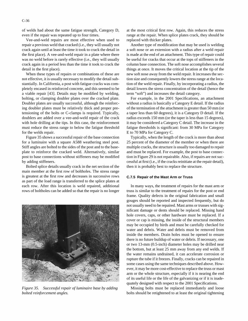
of welds had about the same fatigue strength, Category D,even if the repair was repeated up to four times.
Vee-and-weld repairs are most effective when used torepair a previous weld that cracked (i.e., they will usually notcrack again until at least the time it took to crack the detail inthe first place). A vee-and-weld repair in a plate where therewas no weld before is rarely effective (i.e., they will usuallycrack again in a period less than the time it took to crack thedetail in the first place).
When these types of repairs or combinations of these arenot effective, it is usually necessary to modify the detail sub-stantially. In California, a post with fatigue cracks was com-pletely encased in reinforced concrete, and this seemed to bea viable repair [43]. Details may be modified by welding,bolting, or clamping doubler plates over the cracked plate.Doubler plates are usually successful, although the reinforc-ing doubler plates must be relatively thick and proper pre-tensioning of the bolts or C-clamps is required. Typically,doublers are added over a vee-and-weld repair of the crackwith hole drilling at the tips. In this case, the reinforcementmust reduce the stress range to below the fatigue thresholdfor the welds repair.
Figure 35 shows a successful repair of the base connectionfor a luminaire with a square A588 weathering steel post.Stiff angles are bolted to the sides of the post and to the base-plate to reinforce the cracked weld. Alternatively, similarpost to base connections without stiffeners may be modifiedby adding stiffeners.
Bolted splice details usually crack in the net section of themain member at the first row of boltholes. The stress rangeis greatest at the first row and decreases in successive rowsas part of the load range is transferred to the splice plates ateach row. After this location is weld repaired, additionalrows of boltholes can be added so that the repair is no longer
C-36
at the most critical first row. Again, this reduces the stressrange at the repair. When splice plates crack, they should bereplaced with thicker plates.
Another type of modification that may be used is weldinga soft nose or an extension with a radius after a weld repairis made at the end of an attachment. This type of repair couldbe useful for cracks that occur at the tops of stiffeners in thecolumn base connection. The soft nose accomplishes severalthings at once. It moves the critical location at the tip of thenew soft nose away from the weld repair. It increases the sec-tion size and consequently lowers the stress range at the loca-tion of the weld repair. Finally, by incorporating a radius, thedetail lowers the stress concentration of the detail (hence theterm “soft”) and increases the detail category.
For example, in the 2001 Specifications, an attachmentwithout a radius is basically a Category E detail. If the radiusof the termination of the attachment is greater than 50 mm (ora taper less than 60 degrees), it is a Category D detail. If theradius exceeds 150 mm (or the taper is less than 15 degrees),it may be considered a Category C detail. The increase in thefatigue thresholds is significant: from 30 MPa for CategoryE to 70 MPa for Category C.
Typically, when the length of the crack is more than about25 percent of the diameter of the member or when there aremultiple cracks, the structure is usually too damaged to repairand must be replaced. For example, the post to base connec-tion in Figure 29 is not repairable. Also, if repairs are not suc-cessful at first (i.e., if the cracks reinitiate at the repair detail),then it is probably best to replace the structure.
C.7.5 Repair of the Mast Arm or Truss
In many ways, the treatment of repairs for the mast arm ortruss is similar to the treatment of repairs for the post or endframe. Quality defects in the original fabrication and smallgouges should be reported and inspected frequently, but donot usually need to be repaired. Mast arms or trusses with sig-nificant damage or dents should be replaced. Missing handhole covers, caps, or other hardware must be replaced. If acover or cap is missing, the inside of the structural membersmay be occupied by birds and must be carefully checked forwater and debris. Water and debris must be removed frominside the members. Drain holes must be opened to ensurethere is no future buildup of water or debris. If necessary, oneor two 13-mm (0.5-inch) diameter holes may be drilled nearthe bottom, but at least 25 mm away from any end welds. Ifthe water remains undrained, it can accelerate corrosion orrupture the tube if it freezes. Finally, cracks can be repaired insome cases using the same techniques described above. How-ever, it may be more cost-effective to replace the truss or mastarm or the whole structure, especially if it is nearing the endof its useful life or the life of the galvanizing or if it is inade-quately designed with respect to the 2001 Specifications.
Missing bolts must be replaced immediately and loosebolts should be retightened to at least the original tightening
Figure 35. Successful repair of luminaire base by addingbolted reinforcement angles.
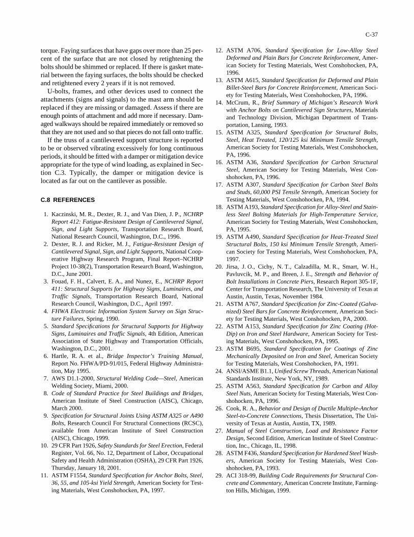
torque. Faying surfaces that have gaps over more than 25 per-cent of the surface that are not closed by retightening thebolts should be shimmed or replaced. If there is gasket mate-rial between the faying surfaces, the bolts should be checkedand retightened every 2 years if it is not removed.
U-bolts, frames, and other devices used to connect theattachments (signs and signals) to the mast arm should bereplaced if they are missing or damaged. Assess if there areenough points of attachment and add more if necessary. Dam-aged walkways should be repaired immediately or removed sothat they are not used and so that pieces do not fall onto traffic.
If the truss of a cantilevered support structure is reportedto be or observed vibrating excessively for long continuousperiods, it should be fitted with a damper or mitigation deviceappropriate for the type of wind loading, as explained in Sec-tion C.3. Typically, the damper or mitigation device islocated as far out on the cantilever as possible.
C.8 REFERENCES
1. Kaczinski, M. R., Dexter, R. J., and Van Dien, J. P., NCHRPReport 412: Fatigue-Resistant Design of Cantilevered Signal,Sign, and Light Supports, Transportation Research Board,National Research Council, Washington, D.C., 1996.
2. Dexter, R. J. and Ricker, M. J., Fatigue-Resistant Design ofCantilevered Signal, Sign, and Light Supports, National Coop-erative Highway Research Program, Final Report–NCHRPProject 10-38(2), Transportation Research Board, Washington,D.C., June 2001.
3. Fouad, F. H., Calvert, E. A., and Nunez, E., NCHRP Report411: Structural Supports for Highway Signs, Luminaires, andTraffic Signals, Transportation Research Board, NationalResearch Council, Washington, D.C., April 1997.
4. FHWA Electronic Information System Survey on Sign Struc-ture Failures, Spring, 1990.
5. Standard Specifications for Structural Supports for HighwaySigns, Luminaires and Traffic Signals, 4th Edition, AmericanAssociation of State Highway and Transportation Officials,Washington, D.C., 2001.
6. Hartle, R. A. et al., Bridge Inspector’s Training Manual,Report No. FHWA/PD-91/015, Federal Highway Administra-tion, May 1995.
7. AWS D1.1-2000, Structural Welding Code—Steel, AmericanWelding Society, Miami, 2000.
8. Code of Standard Practice for Steel Buildings and Bridges,American Institute of Steel Construction (AISC), Chicago,March 2000.
9. Specification for Structural Joints Using ASTM A325 or A490Bolts, Research Council For Structural Connections (RCSC),available from American Institute of Steel Construction(AISC), Chicago, 1999.
10. 29 CFR Part 1926, Safety Standards for Steel Erection, FederalRegister, Vol. 66, No. 12, Department of Labor, OccupationalSafety and Health Administration (OSHA), 29 CFR Part 1926,Thursday, January 18, 2001.
11. ASTM F1554, Standard Specification for Anchor Bolts, Steel,36, 55, and 105-ksi Yield Strength, American Society for Test-ing Materials, West Conshohocken, PA, 1997.
C-37
12. ASTM A706, Standard Specification for Low-Alloy SteelDeformed and Plain Bars for Concrete Reinforcement, Amer-ican Society for Testing Materials, West Conshohocken, PA,1996.
13. ASTM A615, Standard Specification for Deformed and PlainBillet-Steel Bars for Concrete Reinforcement, American Soci-ety for Testing Materials, West Conshohocken, PA, 1996.
14. McCrum, R., Brief Summary of Michigan’s Research Workwith Anchor Bolts on Cantilevered Sign Structures, Materialsand Technology Division, Michigan Department of Trans-portation, Lansing, 1993.
15. ASTM A325, Standard Specification for Structural Bolts,Steel, Heat Treated, 120/125 ksi Minimum Tensile Strength,American Society for Testing Materials, West Conshohocken,PA, 1996.
16. ASTM A36, Standard Specification for Carbon StructuralSteel, American Society for Testing Materials, West Con-shohocken, PA, 1996.
17. ASTM A307, Standard Specification for Carbon Steel Boltsand Studs, 60,000 PSI Tensile Strength, American Society forTesting Materials, West Conshohocken, PA, 1994.
18. ASTM A193, Standard Specification for Alloy-Steel and Stain-less Steel Bolting Materials for High-Temperature Service,American Society for Testing Materials, West Conshohocken,PA, 1995.
19. ASTM A490, Standard Specification for Heat-Treated SteelStructural Bolts, 150 ksi Minimum Tensile Strength, Ameri-can Society for Testing Materials, West Conshohocken, PA,1997.
20. Jirsa, J. O., Cichy, N. T., Calzadilla, M. R., Smart, W. H.,Pavluvcik, M. P., and Breen, J. E., Strength and Behavior ofBolt Installations in Concrete Piers, Research Report 305-1F,Center for Transportation Research, The University of Texas atAustin, Austin, Texas, November 1984.
21. ASTM A767, Standard Specification for Zinc-Coated (Galva-nized) Steel Bars for Concrete Reinforcement, American Soci-ety for Testing Materials, West Conshohocken, PA, 2000.
22. ASTM A153, Standard Specification for Zinc Coating (Hot-Dip) on Iron and Steel Hardware, American Society for Test-ing Materials, West Conshohocken, PA, 1995.
23. ASTM B695, Standard Specification for Coatings of ZincMechanically Deposited on Iron and Steel, American Societyfor Testing Materials, West Conshohocken, PA, 1991.
24. ANSI/ASME B1.1, Unified Screw Threads, American NationalStandards Institute, New York, NY, 1989.
25. ASTM A563, Standard Specification for Carbon and AlloySteel Nuts, American Society for Testing Materials, West Con-shohocken, PA, 1996.
26. Cook, R. A., Behavior and Design of Ductile Multiple-AnchorSteel-to-Concrete Connections, Thesis Dissertation, The Uni-versity of Texas at Austin, Austin, TX, 1989.
27. Manual of Steel Construction, Load and Resistance FactorDesign, Second Edition, American Institute of Steel Construc-tion, Inc., Chicago, IL, 1998.
28. ASTM F436, Standard Specification for Hardened Steel Wash-ers, American Society for Testing Materials, West Con-shohocken, PA, 1993.
29. ACI 318-99, Building Code Requirements for Structural Con-crete and Commentary, American Concrete Institute, Farming-ton Hills, Michigan, 1999.
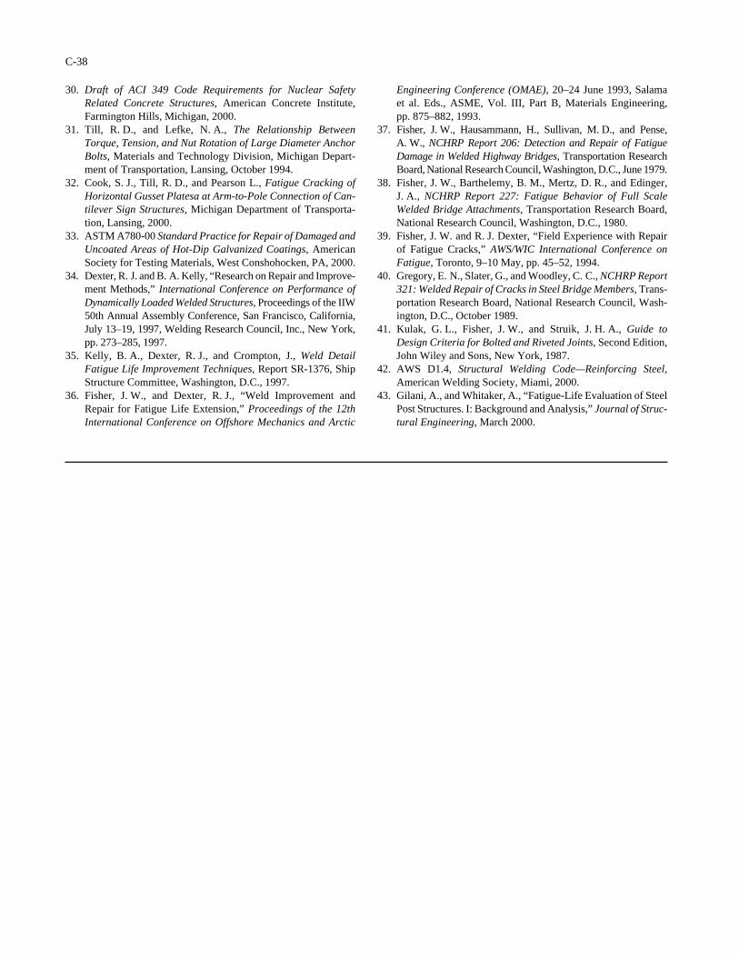
30. Draft of ACI 349 Code Requirements for Nuclear SafetyRelated Concrete Structures, American Concrete Institute,Farmington Hills, Michigan, 2000.
31. Till, R. D., and Lefke, N. A., The Relationship BetweenTorque, Tension, and Nut Rotation of Large Diameter AnchorBolts, Materials and Technology Division, Michigan Depart-ment of Transportation, Lansing, October 1994.
32. Cook, S. J., Till, R. D., and Pearson L., Fatigue Cracking ofHorizontal Gusset Platesa at Arm-to-Pole Connection of Can-tilever Sign Structures, Michigan Department of Transporta-tion, Lansing, 2000.
33. ASTM A780-00 Standard Practice for Repair of Damaged andUncoated Areas of Hot-Dip Galvanized Coatings, AmericanSociety for Testing Materials, West Conshohocken, PA, 2000.
34. Dexter, R. J. and B. A. Kelly, “Research on Repair and Improve-ment Methods,” International Conference on Performance ofDynamically Loaded Welded Structures, Proceedings of the IIW50th Annual Assembly Conference, San Francisco, California,July 13–19, 1997, Welding Research Council, Inc., New York,pp. 273–285, 1997.
35. Kelly, B. A., Dexter, R. J., and Crompton, J., Weld DetailFatigue Life Improvement Techniques, Report SR-1376, ShipStructure Committee, Washington, D.C., 1997.
36. Fisher, J. W., and Dexter, R. J., “Weld Improvement andRepair for Fatigue Life Extension,” Proceedings of the 12thInternational Conference on Offshore Mechanics and Arctic
C-38
Engineering Conference (OMAE), 20–24 June 1993, Salama et al. Eds., ASME, Vol. III, Part B, Materials Engineering, pp. 875–882, 1993.
37. Fisher, J. W., Hausammann, H., Sullivan, M. D., and Pense,A. W., NCHRP Report 206: Detection and Repair of FatigueDamage in Welded Highway Bridges, Transportation ResearchBoard, National Research Council, Washington, D.C., June 1979.
38. Fisher, J. W., Barthelemy, B. M., Mertz, D. R., and Edinger,J. A., NCHRP Report 227: Fatigue Behavior of Full ScaleWelded Bridge Attachments, Transportation Research Board,National Research Council, Washington, D.C., 1980.
39. Fisher, J. W. and R. J. Dexter, “Field Experience with Repairof Fatigue Cracks,” AWS/WIC International Conference onFatigue, Toronto, 9–10 May, pp. 45–52, 1994.
40. Gregory, E. N., Slater, G., and Woodley, C. C., NCHRP Report321: Welded Repair of Cracks in Steel Bridge Members, Trans-portation Research Board, National Research Council, Wash-ington, D.C., October 1989.
41. Kulak, G. L., Fisher, J. W., and Struik, J. H. A., Guide toDesign Criteria for Bolted and Riveted Joints, Second Edition,John Wiley and Sons, New York, 1987.
42. AWS D1.4, Structural Welding Code—Reinforcing Steel,American Welding Society, Miami, 2000.
43. Gilani, A., and Whitaker, A., “Fatigue-Life Evaluation of SteelPost Structures. I: Background and Analysis,” Journal of Struc-tural Engineering, March 2000.

Abbreviations used without definitions in TRB publications:
AASHO American Association of State Highway OfficialsAASHTO American Association of State Highway and Transportation OfficialsASCE American Society of Civil EngineersASME American Society of Mechanical EngineersASTM American Society for Testing and MaterialsFAA Federal Aviation AdministrationFHWA Federal Highway AdministrationFRA Federal Railroad AdministrationFTA Federal Transit AdministrationIEEE Institute of Electrical and Electronics EngineersITE Institute of Transportation EngineersNCHRP National Cooperative Highway Research ProgramNCTRP National Cooperative Transit Research and Development ProgramNHTSA National Highway Traffic Safety AdministrationSAE Society of Automotive EngineersTCRP Transit Cooperative Research ProgramTRB Transportation Research BoardU.S.DOT United States Department of Transportation
Advisers to the Nation on Science, Engineering, and Medicine
National Academy of SciencesNational Academy of EngineeringInstitute of MedicineNational Research Council
The Transportation Research Board is a unit of the National Research Council, which serves the National Academy of Sciences and the National Academy of Engineering. The Board’s mission is to promote innovation and progress in transportation by stimulating and conducting research, facilitating the dissemination of information, and encouraging the implementation of research results. The Board’s varied activities annually draw on approximately 4,000 engineers, scientists, and other transportation researchers and practitioners from the public and private sectors and academia, all of whom contribute their expertise in the public interest. The program is supported by state transportation departments, federal agencies including the component administrations of the U.S. Department of Transportation, and other organizations and individuals interested in the development of transportation.
The National Academy of Sciences is a private, nonprofit, self-perpetuating society of distin-guished scholars engaged in scientific and engineering research, dedicated to the furtherance of science and technology and to their use for the general welfare. Upon the authority of the charter granted to it by the Congress in 1863, the Academy has a mandate that requires it to advise the federal government on scientific and technical matters. Dr. Bruce M. Alberts is president of the National Academy of Sciences.
The National Academy of Engineering was established in 1964, under the charter of the National Academy of Sciences, as a parallel organization of outstanding engineers. It is autonomous in its administration and in the selection of its members, sharing with the National Academy of Sciences the responsibility for advising the federal government. The National Academy of Engineering also sponsors engineering programs aimed at meeting national needs, encourages education and research, and recognizes the superior achievements of engineers. Dr. William A. Wulf is president of the National Academy of Engineering.
The Institute of Medicine was established in 1970 by the National Academy of Sciences to secure the services of eminent members of appropriate professions in the examination of policy matters pertaining to the health of the public. The Institute acts under the responsibility given to the National Academy of Sciences by its congressional charter to be an adviser to the federal government and, upon its own initiative, to identify issues of medical care, research, and education. Dr. Kenneth I. Shine is president of the Institute of Medicine.
The National Research Council was organized by the National Academy of Sciences in 1916 to associate the broad community of science and technology with the Academy’s purpose of furthering knowledge and advising the federal government. Functioning in accordance with general policies determined by the Academy, the Council has become the principal operating agency of both the National Academy of Sciences and the National Academy of Engineering in providing services to the government, the public, and the scientific and engineering communities. The Council is administered jointly by both the Academies and the Institute of Medicine. Dr. Bruce M. Alberts and Dr. William A. Wulf are chairman and vice chairman, respectively, of the National Research Council.