nchrp report 494 – structural supports for highway signs...
TRANSCRIPT
Structural Supports for Highway Signs, Luminaires, and
Traffic Signals
NATIONALCOOPERATIVE HIGHWAYRESEARCH PROGRAMNCHRP
REPORT 494

TRANSPORTATION RESEARCH BOARD EXECUTIVE COMMITTEE 2003 (Membership as of March 2003)
OFFICERSChair: Genevieve Giuliano, Director and Professor, School of Policy, Planning, and Development, University of Southern California,Los AngelesVice Chair: Michael S. Townes, Executive Director, Transportation District Commission of Hampton Roads, Hampton, VA Executive Director: Robert E. Skinner, Jr., Transportation Research Board
MEMBERSMICHAEL W. BEHRENS, Executive Director, Texas DOTJOSEPH H. BOARDMAN, Commissioner, New York State DOTSARAH C. CAMPBELL, President, TransManagement, Inc., Washington, DCE. DEAN CARLSON, Secretary of Transportation, Kansas DOTJOANNE F. CASEY, President, Intermodal Association of North AmericaJAMES C. CODELL III, Secretary, Kentucky Transportation CabinetJOHN L. CRAIG, Director, Nebraska Department of RoadsBERNARD S. GROSECLOSE, JR., President and CEO, South Carolina State Ports AuthoritySUSAN HANSON, Landry University Professor of Geography, Graduate School of Geography, Clark UniversityLESTER A. HOEL, L. A. Lacy Distinguished Professor, Department of Civil Engineering, University of VirginiaHENRY L. HUNGERBEELER, Director, Missouri DOTADIB K. KANAFANI, Cahill Professor and Chairman, Department of Civil and Environmental Engineering, University of California
at Berkeley RONALD F. KIRBY, Director of Transportation Planning, Metropolitan Washington Council of GovernmentsHERBERT S. LEVINSON, Principal, Herbert S. Levinson Transportation Consultant, New Haven, CTMICHAEL D. MEYER, Professor, School of Civil and Environmental Engineering, Georgia Institute of TechnologyJEFF P. MORALES, Director of Transportation, California DOTKAM MOVASSAGHI, Secretary of Transportation, Louisiana Department of Transportation and DevelopmentCAROL A. MURRAY, Commissioner, New Hampshire DOTDAVID PLAVIN, President, Airports Council International, Washington, DCJOHN REBENSDORF, Vice President, Network and Service Planning, Union Pacific Railroad Co., Omaha, NECATHERINE L. ROSS, Executive Director, Georgia Regional Transportation AgencyJOHN M. SAMUELS, Senior Vice President-Operations Planning & Support, Norfolk Southern Corporation, Norfolk, VAPAUL P. SKOUTELAS, CEO, Port Authority of Allegheny County, Pittsburgh, PAMARTIN WACHS, Director, Institute of Transportation Studies, University of California at BerkeleyMICHAEL W. WICKHAM, Chairman and CEO, Roadway Express, Inc., Akron, OH
MIKE ACOTT, President, National Asphalt Pavement Association (ex officio)MARION C. BLAKEY, Federal Aviation Administrator, U.S.DOT (ex officio)REBECCA M. BREWSTER, President and CEO, American Transportation Research Institute, Atlanta, GA (ex officio)THOMAS H. COLLINS (Adm., U.S. Coast Guard), Commandant, U.S. Coast Guard (ex officio)JENNIFER L. DORN, Federal Transit Administrator, U.S.DOT (ex officio)ELLEN G. ENGLEMAN, Research and Special Programs Administrator, U.S.DOT (ex officio)ROBERT B. FLOWERS (Lt. Gen., U.S. Army), Chief of Engineers and Commander, U.S. Army Corps of Engineers (ex officio)HAROLD K. FORSEN, Foreign Secretary, National Academy of Engineering (ex officio)EDWARD R. HAMBERGER, President and CEO, Association of American Railroads (ex officio)JOHN C. HORSLEY, Executive Director, American Association of State Highway and Transportation Officials (ex officio)MICHAEL P. JACKSON, Deputy Secretary of Transportation, U.S.DOT (ex officio)ROGER L. KING, Chief Applications Technologist, National Aeronautics and Space Administration (ex officio)ROBERT S. KIRK, Director, Office of Advanced Automotive Technologies, U.S. Department of Energy (ex officio)RICK KOWALEWSKI, Acting Director, Bureau of Transportation Statistics, U.S.DOT (ex officio)WILLIAM W. MILLAR, President, American Public Transportation Association (ex officio) MARY E. PETERS, Federal Highway Administrator, U.S.DOT (ex officio)SUZANNE RUDZINSKI, Director, Office of Transportation and Air Quality, U.S. Environmental Protection Agency (ex officio)JEFFREY W. RUNGE, National Highway Traffic Safety Administrator, U.S.DOT (ex officio)ALLAN RUTTER, Federal Railroad Administrator, U.S.DOT (ex officio)ANNETTE M. SANDBERG, Deputy Administrator, Federal Motor Carrier Safety Administration, U.S.DOT (ex officio)WILLIAM G. SCHUBERT, Maritime Administrator, U.S.DOT (ex officio)
NATIONAL COOPERATIVE HIGHWAY RESEARCH PROGRAM
Transportation Research Board Executive Committee Subcommittee for NCHRP
GENEVIEVE GIULIANO, University of Southern California, Los Angeles (Chair)
E. DEAN CARLSON, Kansas DOTLESTER A. HOEL, University of VirginiaJOHN C. HORSLEY, American Association of State Highway and
Transportation Officials
MARY E. PETERS, Federal Highway Administration ROBERT E. SKINNER, JR., Transportation Research BoardMICHAEL S. TOWNES, Transportation District Commission
of Hampton Roads, Hampton, VA
T R A N S P O R T A T I O N R E S E A R C H B O A R DWASHINGTON, D.C.
2003www.TRB.org
NATIONAL COOPERATIVE HIGHWAY RESEARCH PROGRAM
NCHRP REPORT 494
Research Sponsored by the American Association of State Highway and Transportation Officials in Cooperation with the Federal Highway Administration
SUBJECT AREAS
Bridges, Other Structures, and Hydraulics and Hydrology
Structural Supports for Highway Signs, Luminaires, and
Traffic Signals
FOUAD H. FOUAD
JAMES S. DAVIDSON
NORBERT DELATTE
ELIZABETH A. CALVERT
SHEN-EN CHEN
EDGAR NUNEZ
RAMY ABDALLA
THE UNIVERSITY OF ALABAMA AT BIRMINGHAM
Birmingham, AL

NATIONAL COOPERATIVE HIGHWAY RESEARCH PROGRAM
Systematic, well-designed research provides the most effectiveapproach to the solution of many problems facing highwayadministrators and engineers. Often, highway problems are of localinterest and can best be studied by highway departmentsindividually or in cooperation with their state universities andothers. However, the accelerating growth of highway transportationdevelops increasingly complex problems of wide interest tohighway authorities. These problems are best studied through acoordinated program of cooperative research.
In recognition of these needs, the highway administrators of theAmerican Association of State Highway and TransportationOfficials initiated in 1962 an objective national highway researchprogram employing modern scientific techniques. This program issupported on a continuing basis by funds from participatingmember states of the Association and it receives the full cooperationand support of the Federal Highway Administration, United StatesDepartment of Transportation.
The Transportation Research Board of the National Academieswas requested by the Association to administer the researchprogram because of the Board’s recognized objectivity andunderstanding of modern research practices. The Board is uniquelysuited for this purpose as it maintains an extensive committeestructure from which authorities on any highway transportationsubject may be drawn; it possesses avenues of communications andcooperation with federal, state and local governmental agencies,universities, and industry; its relationship to the National ResearchCouncil is an insurance of objectivity; it maintains a full-timeresearch correlation staff of specialists in highway transportationmatters to bring the findings of research directly to those who are ina position to use them.
The program is developed on the basis of research needsidentified by chief administrators of the highway and transportationdepartments and by committees of AASHTO. Each year, specificareas of research needs to be included in the program are proposedto the National Research Council and the Board by the AmericanAssociation of State Highway and Transportation Officials.Research projects to fulfill these needs are defined by the Board, andqualified research agencies are selected from those that havesubmitted proposals. Administration and surveillance of researchcontracts are the responsibilities of the National Research Counciland the Transportation Research Board.
The needs for highway research are many, and the NationalCooperative Highway Research Program can make significantcontributions to the solution of highway transportation problems ofmutual concern to many responsible groups. The program,however, is intended to complement rather than to substitute for orduplicate other highway research programs.
Note: The Transportation Research Board of the National Academies, theNational Research Council, the Federal Highway Administration, the AmericanAssociation of State Highway and Transportation Officials, and the individualstates participating in the National Cooperative Highway Research Program donot endorse products or manufacturers. Trade or manufacturers’ names appearherein solely because they are considered essential to the object of this report.
Published reports of the
NATIONAL COOPERATIVE HIGHWAY RESEARCH PROGRAM
are available from:
Transportation Research BoardBusiness Office500 Fifth Street, NWWashington, DC 20001
and can be ordered through the Internet at:
http://www.national-academies.org/trb/bookstore
Printed in the United States of America
NCHRP REPORT 494
Project G17-10(2) FY’98
ISSN 0077-5614
ISBN 0-309-08753-8
Library of Congress Control Number 2003106593
© 2003 Transportation Research Board
Price $19.00
NOTICE
The project that is the subject of this report was a part of the National Cooperative
Highway Research Program conducted by the Transportation Research Board with the
approval of the Governing Board of the National Research Council. Such approval
reflects the Governing Board’s judgment that the program concerned is of national
importance and appropriate with respect to both the purposes and resources of the
National Research Council.
The members of the technical committee selected to monitor this project and to review
this report were chosen for recognized scholarly competence and with due
consideration for the balance of disciplines appropriate to the project. The opinions and
conclusions expressed or implied are those of the research agency that performed the
research, and, while they have been accepted as appropriate by the technical committee,
they are not necessarily those of the Transportation Research Board, the National
Research Council, the American Association of State Highway and Transportation
Officials, or the Federal Highway Administration, U.S. Department of Transportation.
Each report is reviewed and accepted for publication by the technical committee
according to procedures established and monitored by the Transportation Research
Board Executive Committee and the Governing Board of the National Research
Council.

The National Academy of Sciences is a private, nonprofit, self-perpetuating society of distinguished schol-ars engaged in scientific and engineering research, dedicated to the furtherance of science and technology and to their use for the general welfare. On the authority of the charter granted to it by the Congress in 1863, the Academy has a mandate that requires it to advise the federal government on scientific and techni-cal matters. Dr. Bruce M. Alberts is president of the National Academy of Sciences.
The National Academy of Engineering was established in 1964, under the charter of the National Acad-emy of Sciences, as a parallel organization of outstanding engineers. It is autonomous in its administration and in the selection of its members, sharing with the National Academy of Sciences the responsibility for advising the federal government. The National Academy of Engineering also sponsors engineering programs aimed at meeting national needs, encourages education and research, and recognizes the superior achieve-ments of engineers. Dr. William A. Wulf is president of the National Academy of Engineering.
The Institute of Medicine was established in 1970 by the National Academy of Sciences to secure the services of eminent members of appropriate professions in the examination of policy matters pertaining to the health of the public. The Institute acts under the responsibility given to the National Academy of Sciences by its congressional charter to be an adviser to the federal government and, on its own initiative, to identify issues of medical care, research, and education. Dr. Harvey V. Fineberg is president of the Institute of Medicine.
The National Research Council was organized by the National Academy of Sciences in 1916 to associate the broad community of science and technology with the Academy’s purposes of furthering knowledge and advising the federal government. Functioning in accordance with general policies determined by the Acad-emy, the Council has become the principal operating agency of both the National Academy of Sciences and the National Academy of Engineering in providing services to the government, the public, and the scientific and engineering communities. The Council is administered jointly by both the Academies and the Institute of Medicine. Dr. Bruce M. Alberts and Dr. William A. Wulf are chair and vice chair, respectively, of the National Research Council.
The Transportation Research Board is a division of the National Research Council, which serves the National Academy of Sciences and the National Academy of Engineering. The Board’s mission is to promote innovation and progress in transportation by stimulating and conducting research, facilitating the dissemination of information, and encouraging the implementation of research results. The Board’s varied activities annually engage more than 4,000 engineers, scientists, and other transportation researchers and practitioners from the public and private sectors and academia, all of whom contribute their expertise in the public interest. The program is supported by state transportation departments, federal agencies including the component administrations of the U.S. Department of Transportation, and other organizations and individuals interested in the development of transportation. www.TRB.org
www.national-academies.org

COOPERATIVE RESEARCH PROGRAMS STAFF FOR NCHRP REPORT 494
ROBERT J. REILLY, Director, Cooperative Research ProgramsCRAWFORD F. JENCKS, Manager, National Cooperative Highway Research ProgramDAVID B. BEAL, Senior Program OfficerEILEEN P. DELANEY, Managing EditorBETH HATCH, Assistant Editor
NCHRP PROJECT 17-10(2) PANELField of Traffic—Area of Safety
B. PATRICK COLLINS, Wyoming DOT (Chair)MARCUS H. ANSLEY, Florida DOT KENT A. BAHLER, Wisconsin DOTJOHN P. DUSEL, JR., Sacramento, CACARL J. MACCHIETTO, Valmont Industries, Inc., Valley, NEWILLIAM C. MCCARTHY, New Mexico State UniversityRAY C. MINOR, Hapco Division, Abingdon, VACHARLES F. MCDEVITT, FHWA Liaison RepresentativeBILL DEARASAUGH, TRB Liaison Representative
AUTHOR ACKNOWLEDGMENTSThe research reported herein was performed under NCHRP
Project 17-10(2) by the Department of Civil and EnvironmentalEngineering, University of Alabama at Birmingham (UAB).
Dr. Fouad H. Fouad, Professor of Civil Engineering, UAB, wasthe principal investigator. Co-investigators on this project are Dr.James Davidson, Assistant Professor, UAB; Dr. Norbert Delatte,Assistant Professor, UAB; and Ms. Elizabeth A. Calvert, structuraldesign consultant. Additionally, Mr. Edgar Nunez and Mr. RamyAbdalla, both Research Engineers at UAB, and Dr. Shen-En Chen,Assistant Professor, UAB, have provided significant contributions.
The efforts of Ms. Barbara Clements, Senior Engineer, Walpar,Inc., and Mr. Bo Doswell, Principal, SDS Consultants, were invalu-able and are greatly appreciated.
Special thanks are extended to Dr. Kishor Mehta who served asa consultant to the project on wind-related topics. His efforts aregreatly appreciated.
The authors are most grateful to the NCHRP Project 17-10(2)panel members and would like to acknowledge their patience andguidance throughout the study. The panel review sessions, con-ducted by Mr. David Beal and chaired by Mr. Allen F. Laffoon,were particularly helpful to the researchers.

This report contains the findings of a study to develop recommended revisions tothe AASHTO Standard Specifications for Structural Supports for Highway Signs,Luminaires and Traffic Signals. The report describes the research effort and providesrecommendations for updating and refining the specifications. A strategic plan for fur-ther enhancement of the specifications and for conversion of the specifications to loadand resistance factor format is also included. The material in this report will be ofimmediate interest to specification writers, structural engineers, and designers.
The AASHTO Standard Specifications for Structural Supports for Highway Signs,Luminaires and Traffic Signals, fourth edition, includes many of the recommended pro-visions developed in NCHRP Project 17-10. Nevertheless, when those specificationswere published, information needed to provide comprehensive specifications waseither unavailable or incomplete for several topics. In particular, information wasneeded on the consequences of changes in the wind speed map, fatigue in noncan-tilevered structures, foundation selection criteria, drag coefficients for multisidedtapered poles, connection plate flatness criteria, strength of rectangular poles bent aboutthe diagonal, and performance specifications for fiber-reinforced composite structuralelements. A strategic plan for future enhancement of the specifications, including con-version to load and resistance factor design format, also was needed.
Under NCHRP Project 17-10(2), researchers at the University of Alabama at Bir-mingham addressed these topics with the assistance of Elizabeth Calvert. This reportsummarizes the findings and recommendations for each of the topics listed above,which can be used to develop comprehensive support specifications. The enhancementsoutlined in the strategic plan may be undertaken as time and resources permit. A seriesof unpublished appendixes that provide full details of the research findings and rec-ommendations for each topic are available from NCHRP in electronic form.
FOREWORDBy David B. Beal,
Staff OfficerTransportation Research
Board

1 SUMMARY
3 CHAPTER 1 Introduction and Research Approach1.1 Background, 31.2 Research Problem Statement, 31.3 Research Objectives and Approach, 31.4 Scope of the Investigation, 31.5 Organization of the Report, 4
5 CHAPTER 2 Research Findings2.1 Literature Review, Industry Contacts, and Survey, 52.2 Wind Loads Report, 62.3 Fatigue and Vibration in Noncantilevered Support Structures, 62.4 Anchorage to Concrete, 102.5 Foundations, 162.6 Drag Coefficient Transitions for Multisided to Round Cross Sections, 202.7 Connection Plate and Base Plate Flatness Tolerances, 232.8 Square and Rectangular Steel Tubes Bent About a Diagonal Axis, 302.9 Performance Specification for Fiber-Reinforced Composites, 312.10 Inspection, Retrofit, Repair, and Rehabilitation of Fatigue-Damaged
Support Structures, 342.11 Strategic Plan for Future Supports Specifications Enhancements, 35
43 CHAPTER 3 Interpretation, Appraisal, and Application3.1 Wind Loads Report, 433.2 Fatigue and Vibration in Noncantilevered Support Structures, 433.3 Anchorage to Concrete, 433.4 Foundations, 433.5 Drag Coefficient Transitions for Multisided to Round Cross Sections, 433.6 Connection Plate and Base Plate Flatness Tolerances, 433.7 Square and Rectangular Steel Tubes Bent About a Diagonal Axis, 443.8 Performance Specification for Fiber-Reinforced Composites, 443.9 Inspection, Retrofit, Repair, and Rehabilitation of Fatigue-Damaged
Support Structures, 443.10 Design Examples, 443.11 Strategic Plan for Future Supports Specifications Enhancements, 44
45 CHAPTER 4 Summary, Conclusions, and Suggested Research4.1 Summary and Conclusions, 454.2 Implementation, 454.3 Additional Improvements, 45
48 REFERENCES
50 APPENDIXES
CONTENTS
NCHRP Project 17-10 was conducted for the main purpose of revamping the 1994edition of the AASHTO Standard Specifications for Structural Supports for HighwaySigns, Luminaires and Traffic Signals (hereafter referred to as the Supports Specifica-tions). The project addressed specific technical topics; provided major updates based oncurrent codes and standards; presented new wind maps and wind loading criteria; andintroduced new sections on fiber-reinforced composites, wood structures, and fatiguedesign. Project 17-10 resulted in a totally revised Supports Specifications that was sub-mitted to the AASHTO Highway Subcommittee on Bridges and Structures (HSCOBS),adopted in 1999, and published in 2001.
In spite of the extensive research efforts performed under NCHRP Project 17-10, anumber of technical issues still needed further investigation or refinement. The projectpanel identified and prioritized a number of technical topics for study in NCHRPProject 17-10(2). The main objective of NCHRP Project 17-10(2) was to enhance theSupports Specifications developed under Project 17-10 and to provide a strategic planfor future development of the specifications. Specific technical topics addressed byProject 17-10(2) included the following:
• Wind load analysis. A report for consideration by the AASHTO HSCOBS wasprepared to address the basis for the differences in the wind speed maps, the dif-ferences in design loads resulting from wind speed maps, and the treatment ofgusts in the 1994 and 2001 Supports Specifications. Approximate gust effect fac-tors for wind-sensitive structures were also developed.
• Fatigue and vibration in noncantilevered support structures. Fatigue and vibra-tion in noncantilevered support structures were studied, and a set of fatigue loadswas recommended. Additionally, connection details to minimize fatigue effects,effectiveness of gussets in reducing fatigue problems, and vibration-mitigationmeasures were evaluated and documented. The material is presented in a formatthat is suitable for consideration for inclusion in the specifications.
• Foundations and anchor bolts. Selection criteria and design guidance for supportstructure foundations were provided, and a simplified design method for anchor
SUMMARY
STRUCTURAL SUPPORTS FOR HIGHWAY SIGNS,LUMINAIRES, AND TRAFFIC SIGNALS

bolt design was proposed based on state-of-the-art information on anchorage toconcrete.
• Drag coefficient transitions for multisided to round shapes. A drag coefficienttransition equation was developed for tapered poles that transition from multisidedshapes to round shapes.
• Connection plate and base plate flatness tolerances. Current practice and stateDOT specifications were reviewed to identify the need for structure-specific con-nection plate and base plate flatness tolerances for erection. Tolerances based onthe findings were recommended.
• Bending about the diagonal for rectangular steel sections. Strength and failurecriteria for bending about the diagonal axis of rectangular steel sections wereestablished. Design guidelines were developed and proposed for bending about thediagonal for rectangular steel sections.
• Fiber-reinforced composites. A performance specification, including acceptancetesting procedures, was developed for fiber-reinforced composite support struc-tures.
• Design examples. Sixteen design examples that represent good design practice forvarious types of support structures while illustrating key features of the specifica-tions were developed.
• Retrofit and rehabilitation of fatigue-damaged support structures. A report thataddresses for retrofitting and rehabilitating fatigue-damaged support structureswas prepared. Guidance on repair and replacement decisions was also provided aspart of this report.
Furthermore, a strategic plan for future enhancement of the Supports Specifications wasdeveloped, including a plan for conversion of the specifications to load and resistancefactor design (LRFD) philosophy and format. The importance of converting to an LRFDapproach was emphasized, and the necessary analytical work to achieve this conversionwas reviewed.
2

3
CHAPTER 1
INTRODUCTION AND RESEARCH APPROACH
1.1 BACKGROUND
NCHRP Project 17-10, whose results are summarized inNCHRP Report 411 (1), was conducted for the main purposeof revamping the 1994 edition of AASHTO’s Standard Spec-ifications for Structural Supports for Highway Signs, Lumi-naires and Traffic Signals (2) (hereafter referred to as the Sup-ports Specifications). The project addressed specific technicaltopics; provided major updates based on current codes andstandards; presented new wind maps and wind loading crite-ria; and introduced new sections on fiber-reinforced compos-ites, wood structures, and fatigue design. NCHRP Report 411adopted an allowable stress design (ASD) philosophy and waspresented in a user-friendly specification/commentary side-by-side format. Project 17-10 resulted in a totally revised SupportsSpecifications that was submitted to the AASHTO HighwaySubcommittee on Bridges and Structures (HSCOBS), adoptedin 1999 (3), and published in 2001 (4).
1.2 RESEARCH PROBLEM STATEMENT
In spite of the extensive research efforts performed underNCHRP Project 17-10, a number of technical issues stillneeded further investigation or refinement. The project panelidentified and prioritized a number of technical topics forstudy in NCHRP Project 17-10(2). Addressing these topicswould result in a more comprehensive and enhanced state-of-the-art Supports Specifications. The 2001 Supports Specifi-cations also had to be upgraded to the more rational load andresistance factor design (LRFD) philosophy. LRFD was andis the basis for most design specifications, since it provides aconsistent approach with respect to strength evaluation andstructural safety. Furthermore, since the Supports Specifica-tions was and is a comprehensive document incorporatingvarious materials, design criteria, and structure types, a strate-gic plan for future enhancement and maintenance of the spec-ifications was needed.
1.3 RESEARCH OBJECTIVES AND APPROACH
1.3.1 Objectives
The main objective of NCHRP Project 17-10(2) was toaddress a number of additional technical topics to further
enhance the Supports Specifications developed under Project17-10 and to provide a strategic plan for future developmentof the specifications. Topics addressed by Project 17-10(2)included the following:
• Impact of the newly adopted wind loading criteria andwind map;
• Treatment of wind-sensitive structures;• Fatigue of noncantilevered support structures;• Anchor bolt design details, including embedment length
and pretensioning;• Foundation selection criteria;• Drag coefficient transition for multisided tapered poles;• Connection plate flatness criteria;• Flexural strength of square or rectangular steel tube sec-
tions bent about the diagonal;• Performance specifications and acceptance testing for
fiber-reinforced composite members;• A set of complete and detailed design examples illus-
trating the use of the 2001 Supports Specifications;• Retrofitting and rehabilitating of fatigue-damaged struc-
tures; and• Development of a strategic plan for converting the spec-
ifications to an LRFD philosophy and a plan depictingfuture enhancements to the specifications.
1.3.2 Approach
The research consisted of an extensive review and analysisof theoretical and experimental research investigations relatedto the project topics. Unpublished works and currently ongo-ing research studies were also identified and obtained. Theprimary focus was to obtain the most up-to-date technicalinformation that has materialized since the completion ofNCHRP Project 17-10. The assembled information was eval-uated and presented in the form of design equations, allow-able stresses, improved methods of analysis, design details,construction tolerances, procedures for repair of structures,and recommendations for improved design and fabrication.
1.4 SCOPE OF THE INVESTIGATION
The planned work for this project consisted of the follow-ing thirteen tasks:

• Task 1—Literature review, industry contacts, andsurvey. Review relevant practice, performance data,research findings, and other information related to sign,signal, and luminaire structures. This information will beassembled from foreign and domestic technical literatureand from unpublished experiences of engineers, owners,material suppliers, fabricators, and others. Informationon actual field performance is of particular interest.
• Task 2—Wind loads report. Develop a report for con-sideration by HSCOBS that addresses the basis for thedifferences in the wind speed maps, the differences indesign loads resulting from wind speed maps, and thetreatment of gusts in the current specifications and thespecifications proposed in NCHRP Project 17-10. Usethe information in ANSI/ASCE 7-95 or successor doc-ument to develop gust effect factors using the proce-dures presented in its commentary for wind-sensitivestructures.
• Task 3—Interim report. Submit an interim report,within 6 months, that documents the results of Tasks 1and 2 and expands on the work plan for Tasks 4 through13. Following project panel review of the interim report,meet with the panel to discuss the interim report andremaining tasks.
• Task 4—Fatigue and vibration in noncantileveredsupport structures. Develop a report for considerationby the AASHTO HSCOBS that addresses fatigue andvibration in noncantilevered support structures. The reportshall include (a) proposed connection design detailingthat minimizes fatigue effects for support structures otherthan cantilevered, (b) an evaluation of the effectivenessof gussets in reducing fatigue problems, (c) recommen-dations for appropriate design and fabrication guide-lines, and (d) proposed vibration mitigation measures.All material shall be prepared in a format suitable forconsideration for inclusion in the specifications.
• Task 5—Foundations and anchor bolts. Provide selec-tion criteria and design guidance for support-structurefoundations, including reinforced and unreinforced cast-in-place drilled piles, steel screw-in foundations, andspread footings. Include design details for anchor bolts. Ata minimum, address anchorage type (hooked or straight),embedment length, and pretensioning.
• Task 6—Drag coefficient transitions for multisided toround shapes. Use existing research findings to developdrag coefficients for tapered poles that transition frommultisided shapes to round shapes.
• Task 7—Connection plate and base plate flatnesstolerances. Review current practice to identify the needfor structure-specific connection plate and base plate
4
flatness tolerances for erection. Recommend tolerancesbased on the findings.
• Task 8—Bending about the diagonal for rectangularsteel sections. Establish strength and failure criteria forbending about the diagonal axis of rectangular sections.Recommend design guidelines.
• Task 9—Fiber-reinforced composites. Develop per-formance specifications and acceptance testing proce-dures for fiber-reinforced composite support structures.
• Task 10—Design examples. Prepare complete designexamples that show good design practice for supportstructures while illustrating key features of the specifi-cations. Examples shall cover a realistic number of struc-ture types covered by the specification. At least oneexample shall be prepared for each material covered inthe specification.
• Task 11—Retrofit and rehabilitation of fatigue-damaged support structures. Prepare a manual forretrofitting and rehabilitating fatigue-damaged supportstructures. It is anticipated that this manual can bedeveloped using the experience of the states and fabri-cators. Guidance on repair/replacement decisions is alsoprovided.
• Task 12—Strategic plan for future enhancements.Develop a strategic plan for future enhancements tothe support structure specifications. In particular, a planfor conversion of the specifications to LRFD philoso-phy and format shall be developed. The strategic planincludes a discussion of data requirements and necessaryexperimental and analytical work needed for LRFDspecifications.
• Task 13—Final report. Submit a final report that doc-uments the entire research effort. The reports developedin Tasks 2, 4, and 11 and the design examples preparedin Task 10 shall be included as separate appendices.Where applicable, suggested changes to the specifica-tions are recommended.
1.5 ORGANIZATION OF THE REPORT
Chapter 2 summarizes the work performed and findingsthat fulfill the 12 objectives of the project. Chapter 3 dis-cusses the proposed technical revisions to the specifica-tions and the recommended changes. Chapter 4 providesthe study conclusions and suggested topics for futureresearch. The appendixes provide detailed reports on selectedtopics.

5
CHAPTER 2
RESEARCH FINDINGS
The project initially focused on 12 topics that were identi-fied as needing revisions and updates. The following is a listof the topics that were studied in this project:
• Impact of the newly adopted wind loading criteria andwind map;
• Treatment of wind-sensitive structures;• Fatigue of noncantilevered support structures;• Anchor bolt design details, including embedment length
and pretensioning;• Foundation selection criteria;• Drag coefficient transition for multisided tapered poles
where the cross-section is nearly round;• Connection plate flatness criteria;• Flexural strength of square or rectangular steel tube sec-
tions bent about the diagonal;• Performance specifications and acceptance testing for
fiber-reinforced composite members;• Retrofitting and rehabilitating of fatigue-damaged struc-
tures; • A set of complete and detailed design examples illus-
trating the use of the 2001 Supports Specifications; and• Development of a strategic plan for converting the spec-
ifications to an LRFD philosophy and a plan depictingfuture enhancements to the specifications.
This chapter summarizes the work performed and the researchfindings. Where applicable, suggested changes to the speci-fications are described.
2.1 LITERATURE REVIEW, INDUSTRYCONTACTS, AND SURVEY
The work for the project included reviewing relevant prac-tice; performance data; research findings; and other informa-tion related to sign, signal, and luminaire support structures.This information was assembled from foreign and domes-tic technical literature and from unpublished experiences ofengineers, owners, material suppliers, fabricators, and oth-ers. Information on actual field performance was of partic-ular interest.
It is recognized that a significant portion of NCHRP Proj-ect 17-10(2) work was of a practical nature, depending onfield experiences, and was not readily available in the pub-lished literature. Hence, much of the information developedin the project was based on the experiences of state depart-ments of transportation (DOTs), manufacturers of supportstructures, material suppliers, and engineers. Close contactswith these parties were maintained throughout the durationof the project and provided an essential ingredient to the suc-cess of the project. Information gained from these sourceswas studied and evaluated with special care, since no offi-cial peer-reviewed publication of the material is available.Based on the surveys of Task 1, the state DOTs and manu-facturers with the most pertinent information related to Proj-ect 17-10(2) were identified. Typical state DOTs that werecontacted included Wyoming, Florida, New York, Califor-nia, Michigan, Texas, and Virginia. Typical manufacturersthat were contacted included Hapco, Newmark, P&K PoleProducts, Shakespeare, Strongwell, Union Metal, Valmont,Walpar, and Whatley. Visits, as necessary, were made togather test data and discuss important details and designinformation.
2.1.1 State DOT Survey and Results
The survey sent by the research team to state DOTs, aswell as the results of that survey, are given in Appendix A.Forty-seven agencies responded. Many state DOTs providedmaterials such as repair manuals, sample calculations, andsample designs that were referenced in later stages of thisresearch. Some states also identified additional manufactur-ers that were contacted.
2.1.2 Manufacturers’ Survey and Results
The survey sent by the research team to support struc-ture manufacturers, as well as the results of that survey, are provided in Appendix A. In addition to survey responses,some of the support structure manufacturers provided sam-ple drawings, test data, calculations, and product catalogs,which were reviewed as part of the project work. Additional

manufacturers identified by state DOTs were contacted toexpand on this information.
2.2 WIND LOADS REPORT
The 2001 Supports Specifications has been updated toreflect currently accepted wind engineering practice. Windloading provisions in the specifications are based on ASCE7-95 (5), with specific modifications for structural supportsfor highway signs, luminaires, and traffic signals. The newwind load provisions in the Supports Specifications are basedon a 3-second gust wind speed, rather than a fastest-milewind speed, and a new map has been adopted. An increase orreduction in calculated wind pressures result from the use ofthe updated wind map.
The main goal of this task is to provide an in-depth expla-nation of the new wind map (3-second gust) and its impacton the calculated design wind pressures on structural sup-ports. In addition, the flexibility of the structural support asit affects the gust effect factors is considered, and methodsfor incorporating the flexibility of the structure in the windloading computation are evaluated.
A complete document entitled “Wind Loads Report” isprovided in Appendix B. It provides a detailed study of thenew wind load provisions in the 2001 Supports Specifica-tions. More specifically, the report addresses the following:
• The basis for wind pressure calculations in the 1994 and2001 specifications,
• Wind load comparisons between the 1994 and the 2001specifications,
• Recommendations for gust effect factors for flexiblestructures, and
• Suggested research needs pertaining to wind loads forstructural supports.
Analytical studies performed showed that the new windprovisions will generally result in wind provisions that willbe significantly different from those calculated using the1994 Supports Specifications. On average, wind loads on sup-port structures, except for an increase for roadside signs,computed in accordance with the new wind provisions arecomparable to the loads computed using the 1994 SupportsSpecifications. In comparing the 1994 and 2001 SupportsSpecifications wind load provisions, it is apparent that changesin wind pressure, either decreasing or increasing, are highlysite specific. The wind pressures will double for a short street-lighting pole in Mobile, Alabama, or Orlando, Florida. Thewind pressures will be reduced by half for a roadside sign inHawaii.
The effect of the flexibility of support structures on thegust effect factor was studied. Equations provided by ASCE
6
7-98 for wind-sensitive structures were reviewed to deter-mine the applicability to support structures. Simplified equa-tions were developed for high mast lighting and traffic sig-nal structures. These equations should be used with cautionand may result in an increase in wind pressure on the struc-tures. Until further verification of these equations using windtunnel testing, it is recommended that they be used for gen-eral guidance.
2.3 FATIGUE AND VIBRATION INNONCANTILEVERED SUPPORTSTRUCTURES
The 1994 edition of the Supports Specifications provideslittle guidance on the design for fatigue and vibration. NCHRPProject 17-10 introduced a new section entitled “FatigueDesign,” which is based primarily on the work of NCHRPProject 10-38 (6). The “Fatigue Design” section of the Sup-ports Specifications addresses fatigue design of cantileveredsteel and aluminum structures. Noncantilevered structureswere not included, since such structures were not within thescope of NCHRP Project 10-38. Therefore, the overall objec-tive of the task represented by this section of the report wasto address fatigue and vibration in noncantilevered supportstructures.
The results of the survey sent to state DOTs indicated con-cerns for fatigue of noncantilevered support structures. Out ofthe 48 replies received, 8 identified problems with noncan-tilevered support structures. State DOTs that indicated hav-ing experienced problems were contacted. Also, the researchteam met with researchers of NCHRP Project 10-38(2) andvisited a local sign support manufacturer. The effort includeda comprehensive literature review of up-to-date publicationsregarding the fatigue of support structures. Related issuessuch as vibration mitigation methods and the effects of gus-sets were also investigated. Finally, an in-depth analyticalinvestigation, using finite element analysis, was conducted todetermine equivalent static fatigue loads for noncantileveredstructures. This section summarizes the major research find-ings of this work. A detailed report documenting the analyt-ical procedures and results is presented in Appendix C. TheDOT survey results regarding fatigue and vibration in non-cantilevered support structures is provided in the appendix,as well as an extensive reference list.
2.3.1 Susceptibility of Noncantilevered SupportStructures to Wind-Induced Vibration
Fatigue and vibration problems that have occurred in non-cantilevered support structures were investigated. However,the question of susceptibility to wind vibration phenomena

such as galloping and vortex shedding is unresolved. A pre-sentation of the different wind loading phenomena and whythey occur, along with a discussion of the susceptibility issue,is provided in Appendix C, where it is pointed out that labo-ratory testing and further field evaluation are needed to deter-mine susceptibility. Such testing was not included in the scopeof this project. However, the research continued with the taskof establishing equivalent static fatigue loads by assumingthat noncantilevered structures were susceptible to the samevibration phenomena as cantilevered support structures andby using the finite element methods as an analysis tool. As aresult of communication with researchers, manufacturers,and state DOT engineers regarding susceptibility issues, gal-loping loads were excluded for truss support structures whilethe loads for other types of noncantilevered support struc-tures were adjusted using importance factors that are similarto the factors used for cantilevered structures.
2.3.2 Establishing Equivalent Static FatigueLoads for Noncantilevered SupportStructures
Finite element analyses were conducted using six sup-port structure models to determine the applicability of thefatigue loads for cantilevered support structures recom-mended by NCHRP Project 10-38 to noncantilevered sup-port structures. The analytical study, which is presented inAppendix C, resulted in the following load recommenda-tions for noncantilevered support structures:
• Galloping. Apply 21-psf shear pressure vertically to theprojected area of the signs mounted to monotube sup-port structures as viewed in the normal elevation (sameas cantilevered support structures). Galloping will onlyapply to horizontal monotubes; noncantilever structuresand truss-type supports are excluded.
• Vortex shedding. Apply the static load model for vor-tex shedding of a cantilevered nontapered element inthe support specifications suggested by NCHRP Proj-ect 17-10 to the nontapered element in the noncan-tilevered support structure. This model involves the trans-verse application of the equivalent static pressure rangeto a nontapered horizontal member (vertical direction) ofthe monotube structures. This design requirement maybe disregarded as long as the signs or sign blanks areused during construction.
• Natural wind loads. Use the value of 5.2 psf multipliedby the drag coefficient, which is the same value as thatused for cantilevered structures. The natural wind gustpressure range shall be applied in the horizontal direc-tion to the exposed area of all support structure mem-bers, signs, and attachments.
7
• Truck-induced loads. Use 7.5 psf for the horizontalpressure applied to the area of the sign and the area ofthe support structures and 10.2 psf for vertical pressureapplied to the area of the support structure and the pro-jected area of the sign. These pressures should be appliedalong the entire span of the structure or along 24 feet ofthe span, whichever is smaller.
• Deflection. Use the limits as provided in the currentspecifications of L/150 for deflection due to dead loadand ice load and not excessive for vertical deflection dueto galloping and vertical truck-induced fatigue loads.
It should be pointed out that the recommendations werebased on the analysis of selected support structures. Exper-imental work is needed to verify the susceptibility of thesestructures to the vibration phenomenon. Because of the lackof such experimental work and fatigue case documentation,the research team used fatigue design loads developed fromthe analytical study as a basis to correlate the loads for non-cantilevered support structures with the loads used for can-tilevered structures and applied importance factors to adjustthese load values. Importance factors for noncantileveredsupport structures were based on discussions with otherresearchers and NCHRP Project 17-10(2) panel comments.These factors are similar to the factors for cantilevered signsupport structures. Galloping was excluded as a loading casefor truss support structures because other researchers indi-cated that noncantilevered truss support structures are notsusceptible to galloping. Section 2.3.6 introduces impor-tance factors for vibration and fatigue design for noncan-tilevered sign support structures.
2.3.3 Fatigue Categorization of ConnectionDetails for Noncantilevered SupportStructures
The research team reviewed sign support structure draw-ings and specifications provided by state DOTs. The researchteam also studied NCHRP reports dealing with fatigue inbridge connections that provided the basis for categorizationin the AASHTO LRFD Bridge Design Specifications (7).Details for noncantilevered support structures were com-pared with the cantilevered structure details and were cate-gorized. The various types of connections, the factors thataffect the fatigue resistance of welded connections, and thefatigue resistance of bolted connections were synthesized.Categorization of details was suggested. Ten examples ofthese connection details are presented in Appendix C. Theconnections included the typical beam column connectionsin monotube support structures, splice joints in monotubesupport structures, and U-bolts used in the chord to theupright connection in truss structures.

2.3.4 Effectiveness of Gussets in Sign SupportStructures
Results of the effectiveness of gussets in sign supportstructures were based on a study by Gilani and Whittaker (8,9). An example that demonstrates the effect of gusset plateswas provided. Providing gusset plates was recommended toincrease the moment capacity of the connection. The momentcapacity can be further increased by appropriate design ofthe gusset.
2.3.5 Vibration Mitigation Measures in SignSupport Structures
Various vibration mitigation measures were studied.These include those considered by Kaczinski et al. (6), Cooket al. in Florida (9a), and Hamilton et al. in Wyoming (9b).The effectiveness of these measures in increasing the damp-ing in support structures was discussed. A brief analyticalstudy was conducted to demonstrate the effect of increaseddamping. Some of the devices were shown to increase thedamping; however, the only way to verify the effectivenessof vibration mitigation is through testing and/or monitoringof structures in service.
2.3.6 Suggested Additions to Section 11 of the2001 Specifications
Add to Specifications, Section 11.4:
d) Noncantilevered overhead sign and traffic signal sup-port structures
Add to Specifications, Table 11-1:
Importance Factors for Vibration and Fatigue Design forNoncantilevered Sign Support Structures
8
support structures do not appear to be susceptible to gal-loping because of their inherently high degree of three-dimensional rigidity.
Add to Specifications, Section 11.7.2:
The equivalent static pressure PVS shall be applied trans-versely (vertical direction) to nontapered horizontal mono-tubes of noncantilevered support structures if signs or signblanks are not used during construction.
Change to Specifications, Section 11.7.3:
From “Overhead cantilever . . .” to “Overhead cantileveredand noncantilevered . . .”
Add to Specifications, Section 11.7.4:
Noncantilevered overhead sign and traffic signal supportstructures shall be designed to resist the following static,truck-induced, gust pressure range of
PTG = 360CdIF (Pa) Eq. 11-7
PTG = 7.5 CdIF (psf)
PTG = 490CdIF (Pa) Eq. 11-8
PTG = 10.2CdIF (psf)
The pressure range given by Eq. 11-7 shall be applied hor-izontally to the area of signs and horizontal members,while the values given by Eq. 11-8 shall be applied in thevertical direction to the area of the structure elements andthe projected area of the sign. These pressures should beapplied along the entire span of the structure or 24 feet (8meters) of the span, whichever is smaller.
Add to Commentary, Section 11.7.4:
Regarding the noncantilevered sign support structures, thepressure values were based on analytical work of projectNCHRP Project 17-10(2) considering truck-induced pres-sure values measured by Cook (1996). The values mea-sured were applied to four noncantilever sign support struc-tures as a dynamic load, and the equivalent static loadswere obtained. The average value of the static loads wasthen multiplied by the factor of 1.3 to account for increasein the relative truck speed due to head wind.
Change to Specifications, Section 11.8 (Deflection):
From “cantilevered single-arm . . .” to “cantilevered single-arm and noncantilevered monotube . . .”
Change to Specifications, Section 11.7.1:
From “Overhead cantilever . . .” to “Overhead cantileveredand noncantilevered . . .”
Add to Specifications, Section 11.7.1, Commentary:
Galloping loads are applied to monotube noncantileveredsupport structures. Overhead noncantilevered truss-type
Importance Factors Category Structure Type Galloping Vortex
shedding Natural Wind
Truck Gust
I Truss Monotube
X 1.0
X X*
1.0 1.0
1.0 1.0
II Truss Monotube
X 0.72
X X*
0.85 0.85
0.9 0.9
* Use the value of 1.0 for construction stage if signs or sign blanks are not used.

Add to Specifications, Table 11-2:
9
Add to the Specifications, Figure 11-1:
Construction Detail Stress
Category
Application Example
Mechanically
Fastened
Connections
25. Bolts in tension D Beam column connection for
monotube structures
16
Fillet-Welded
Connections
26. Fillet weld with one side
normal to the applied stress
E’ Beam column connection for
monotube structures
16
Mechanically
Fastened
Connections
27. High-strength bolts in
tension
D Monotube or truss-chord splice 17
Fillet-Welded
Connections
28. Fillet weld with one side
normal to the applied stress
E’ Monotube or truss-chord splice 17
Mechanically
Fastened
Connections
29. U-bolts tied to the
transverse truss column to
keep the chords in place
D Horizontal truss connection with
the vertical truss
18
Mechanically
Fastened
Connections
30. Net section of full-
tightened, high-tension
bolts in shear
B Truss-bolted joint 18
2.4 ANCHORAGE TO CONCRETE
The 2001 Supports Specifications document does notaddress the design of anchorage to concrete. NCHRP Proj-ect 17-10 proposed a revision to the 1994 AASHTO Sup-ports Specifications and addressed the issue of anchor boltdesign, among other topics (10, 11). On the issue of anchorbolt design, the topics addressed were anchor bolt materi-als, allowable stresses, the use of hooked bolts, minimumembedment length of headed cast-in-place anchor bolts, theeffect of edge distance, and the effect of spacing betweenanchor bolts.
The latest American Concrete Institute (ACI) anchorageprocedure was evaluated. This procedure has been publishedby a number of sources, including the ASCE (12), the Inter-national Conference of Building Officials (13), and Cook (14).The procedure was published as Appendix D in the 2002 edi-tion of the ACI 318 Building Code Requirements for Struc-tural Concrete and Commentary.
The research team obtained an updated copy of this proce-dure, which includes the use of anchor bolts over 25 inches inlength outlined in document CB-30, dated June of 2000 (16).This is the current state of the art in anchorage to concrete.The procedure is presented in a LRFD format. Using a windload factor of 1.3 in accordance with ACI 318 (15), and theappropriate strength reduction factors (φ) (16), the equationshave been converted for use in the Supports Specifications.
2.4.1 NCHRP Report 411 Recommendations
The 1994 edition of the Supports Specifications (2) con-tains little information on the design of embedment length,effect of edge distance, spacing of anchors, or fatigue ofanchors in tension (1). NCHRP Project 17-10 reviewed 17documents and proposed a revision to the anchor bolt sectionof the 1994 Supports Specifications. The project addressedthe following issues:
• Anchor bolt material,• Allowable stresses, and • The use of hooked bolts.
Appendix C was added to the report and addressed thesetopics:
• Minimum embedment length of headed cast-in-placeanchor bolts,
• The effect of edge distance, and • The effect of spacing between anchor bolts.
However, Appendix C was not included in the 2001 AASHTOSupports Specifications (4).
10
2.4.1.1 Anchor Bolt Materials
The 1994 Supports Specifications allowed many differenttypes of anchoring materials, including anchor bolts, boltsmade from reinforcing steel, and other threaded materials (1).NCHRP Report 411 proposed that anchor materials be lim-ited to grades 36-, 55-, and 105-ksi steel because of informa-tion from AASHTO M314 and other ASTM standards.
Tension in the anchor bolt is resisted by bearing of theembedded anchor end on the concrete. The bearing area maybe provided by one of the following:
• Headed bolt,• Headed bolt with washer,• Nut,• Nut with washer, and• Hook of bent bolt.
2.4.1.2 Allowable Stress
NCHRP Report 411 compared the allowable tensile andshear stresses in the current Supports Specifications to thosein the American Institute of Steel Construction (AISC) man-ual. The failure mode of the 1994 Supports Specifications isbased on the yield stress and tensile stress area. It allowed fora tensile stress of 50% of the yield stress and an allowableshear stress of 30% of the yield stress. In the AISC ASD pro-cedure, the allowable tensile stress is limited to 33% of theultimate stress, and the allowable shear stress is limited to17% of the ultimate stress (17). This limit differs from steeldesign in the AISC LRFD manual, which bases its failure onultimate strength and nominal area (18). NCHRP Report 411recommended that the current Supports Specifications allow-able stresses remain at 50% of yield stress (Fy) for tensileloads because it was the more conservative value (1). Thiscautious approach seemed appropriate because of the lack ofinformation at the time that the report was written.
2.4.1.3 Use of Hooked Bolts
NCHRP Report 411 recommended the use of headedanchor bolts over hooked bolts, but allowed hooked bolts upto 55-ksi steel, since research showed that hooked anchorbolts made from higher-strength steel did not develop theirfull tensile strength. Headed bolts give much more efficientpullout strengths than hooked bolts because hooked bolts canstraighten and pull out under high tensile loads, and crushingin the concrete occurs at the area of the hook. It also noted thatAISC LRFD (18) states that high-strength steels are notrecommended for use in hooked bolts because bending withheat might materially alter the steel’s strength. Also, ACI355.1R-91 states that hooked bolts have been known tostraighten out in pullout tests, and headed anchors of thesame size and length have significantly higher capacities (19).

Nevertheless, hooked anchor bolts should be allowed becausea larger-diameter hooked bolt may be cheaper than a smaller-diameter headed bolt of equivalent capacity.
2.4.2 Review of Current State TransportationAgency Practice
State transportation agencies were asked about typical boltmaterials, diameters, and lengths. The results are reported inTables 15 to 21 of Appendix A. The survey results indicatedthat a wide variety of anchor bolt strengths are in use, withASTM A36, A307, and A325 being the most common. Boltdiameters ranged from a minimum of 0.5 inch to a maximumof 2.5 to 3.25 inches, depending on the type of structure.Average bolt diameters were between 1 and 2 inches for allstructure types investigated.
Anchor bolt lengths varied considerably. For street lightpoles, bolt lengths ranged from 12 to 90 inches, with an aver-age of approximately 40 inches. For overhead cantileverstructures, bolt lengths ranged from 30 to 180 inches, with anaverage of approximately 58 inches. Reported anchor boltlengths were between these values for other structure types.The longest values reported by state transportation agenciesexceeded the shortest by a factor of 4 to 7.5, depending ontype of structure, indicating that there is a lack of standard-ization in design procedures.
Both hooked and straight anchor bolts are commonly used.Hooked bolts are used most commonly for lightly loadedstructures such as traffic signal supports and street light sup-ports (60% to 70% of structures). Straight anchor bolts areoften used for heavily loaded structure types such as over-head bridge, overhead cantilever, and high-level lighting poles(42% to 63% of structures). Pretensioned bolts are rarely used,with only 5% to 10.5% usage reported, depending on struc-ture type.
2.4.3 Review of the ACI Anchor Bolt DesignProcedure
As of the late 1990s, the main source of information oncast-in-place anchors to concrete was ACI 349 Appendix B(20) and the PCI Design Handbook (21). Recently, the pro-posed Appendix D of ACI 318-02—published in Appen-dixes A and B of Portland Cement Association publicationStrength Design of Anchorage to Concrete (14), in ASCEStandard 7-98 (12), and in the 2000 International BuildingCode (13)—has become the most current and complete infor-mation on anchorage to concrete.
This procedure has been in development since the mid1970s, when ACI 349 Appendix B (20) and PCI Design Hand-book (21) adopted the 45-degree cone method. The 45-degreecone method was developed from tests conducted at the Uni-versity of Tennessee for the Tennessee Valley Authority. Inthe late 1980s, tests at the University of Stuttgart led to the
11
development of the Kappa method. This development wasbased on tests conducted on different types of anchor materi-als, with a variety of embedment lengths and edge distances.
In the mid-1990s, the Kappa method was refined andmade easier to use by the original developers of the Kappamethod, which resulted in the Concrete Capacity Design(CCD) method. Meanwhile, an international database wascompiled from anchor tests and field performance. ACIcommittees 318, 349, and 355 evaluated the CCD methodand 45-degree cone method using this database. The resultwas to recommend the CCD method proposed as ACI 318Appendix D (15). In this method, the concrete breakoutstrength calculations are based on the same model suggestedby the Kappa method, which assumes a prism angle of 35degrees.
The design procedure is based on ultimate strength design.The procedure applies to headed studs, headed bolts, hookedbolts, and cast-in-place anchors, but not post-installed anchors.The procedure is for static loads and does not apply to fatigueor impact loading. The procedure is not for loads from blastsand shock waves.
For bolts more than 25 inches long, additional reinforce-ment in the direction of the load must be added (16). Appen-dix D of the 2002 edition of the ACI 318 is outlined in theJune 2000 revision of draft CB-30 (16). The ACI procedurerefers to Chapter 12 of ACI 318 for attaching rebar to theanchor (15) in cases where anchors are spliced to reinforcingsteel. The procedure addresses both the strength of the steelanchors and the strength related to the embedment in the con-crete, with the smallest capacity controlling the design. Thestrength of the steel anchors is based on the steel propertiesand size of the anchor. The strength of the embedment isbased on embedment depth, spacing, concrete strength, edgedistance, and size of the head or hook. Concrete strengthsshould be limited to 10,000 psi with this procedure.
2.4.4 Basic Principles
The ACI procedure provides for tension and shear fail-ure modes and for tension-shear interaction. Tension failuremodes include steel strength of anchor in tension, concretebreakout strength of anchor in tension, pullout strength ofanchor in tension, and concrete side-face blowout strength ofanchor in tension. If concrete breakout and concrete side-faceblowout are prevented by using confining reinforcement inthe foundation, then only the steel strength of the anchor andthe pullout strength of the anchor need to be considered fordetermining tension capacity.
Shear failure modes include steel strength of anchor inshear and concrete breakout strength of anchor in shear. Ifconfining reinforcement is provided, concrete breakout inshear can be prevented. Failure may also occur through inter-action between tension and shear.

2.4.5 Proposed Simplified Procedure
A simplified design procedure for anchor bolt design hasbeen developed. It is primarily based on the new provisionson anchoring to concrete that are provided as Appendix D inthe 2002 edition of ACI 318 Building Code Requirements forStructural Concrete and Commentary. The procedure is lim-ited to the following conditions:
• Anchor bolts are hooked or headed;• Foundations have vertical reinforcing steel and confin-
ing reinforcement, with anchor bolts placed inside of thereinforcement;
• Foundation-reinforcing steel is uncoated; and• If hooked bolts are used, the length of the hook is at least
4.5 times the anchor bolt diameter.
For cases where these assumptions do not apply, such aswhen lightly loaded bolts are embedded in an unreinforcedfoundation, designers should refer to the complete procedureas documented in several sources (12–15). It is assumed thatshear will not govern capacity, since the high aspect ratio ofsupport structures ensures that tension bolt forces due tooverturning moment are higher than bolt shear forces by afactor of 14 or more. Moreover, the use of confining rein-forcement will prevent shear breakout.
Briefly, the procedure requires determination of (a) therequired anchor bolt diameter and bearing area for headedbolts or (b) the required anchor bolt diameter for hookedbolts. Next, the bolt length is determined so that the failureplane will intersect the foundation-reinforcing steel belowthe point where the capacity of the reinforcing steel is fullydeveloped. These equations are developed using a wind loadfactor of 1.3 and the appropriate ACI strength reduction fac-tors (φ) of 0.80 for steel strength and 0.75 for concrete bear-ing, solving for required diameters.
Previous design procedures did not account for anchor bolthead or hook bearing against concrete. High bearing stressescan lead to localized concrete crushing, loose anchor bolts,and, thus, poor structure performance.
2.4.5.1 Headed Bolt Diameter
The category of headed bolts includes (a) bolts withhead-bearing area increased by using nuts or washers and(b) threaded rods with nuts, with or without washers. Therequired bolt diameter, based on steel strength, is
(Eq. 1)
Where
N = tensile force on anchor bolt andFut = ultimate tensile strength of bolt, but not more than 1.9
times the bolt yield strength (1.9 Fy), or 125,000 psi.
d NFut
anchor = 1 44.
12
2.4.5.2 Threaded Rod Adjustment
For threaded bolts, the bolt diameter, danchor, must beadjusted to account for the threads. The adjusted diameter,d ′anchor, is increased as follows, using an adaptation of a for-mula from the CB-30 procedure commentary (16):
(Eq. 2)
Where
nt = number of threads per inch.
2.4.5.3 Bolt Head Diameter
The required bearing area of the anchor bolt head, Ab, is
(Eq. 3)
Where
f ′c = specified compressive strength of the concrete.
Bearing areas for various bolt sizes are provided in Table 2of Cook (14). Therefore, for a round washer, the required bolthead diameter, dhead, is
(Eq. 4)
For this equation, the actual anchor bolt diameter, not the min-imum, must be used. This requirement is important becausethe required bolt diameter will be rounded up to the next avail-able size. If the actual diameter is not used in the equationabove, the equation will not necessarily provide sufficientbearing area. The required area may be provided by a bolthead, by a nut, or by a washer on top of a bolt head or nut.
2.4.5.4 Hooked Bolt Diameter
The required bolt diameter to prevent crushing failure ofthe concrete against the hook is
(Eq. 5)
This formula assumes that the distance from the inner surfaceof the shaft of a J-bolt or L-bolt to the outer tip of the J-boltor L-bolt (eh) is a minimum of 4.5 times the anchor diameter.
Anchor bolt steel strength should also be checked. How-ever, combining the first equation with the hooked bolt equa-tion indicates that the concrete bearing strength will govern
d Nfc
anchor =′
0 614.
d A dbhead anchor= + ′4 2
π
A Nfbc
=′
0 191.
′ = +
d d
ntanchor anchor 1 0 9743.

unless concrete strength f ′c is at least 18% of Fut. Since A36steel would require concrete with a strength of over 10,400psi, it may safely be assumed that steel strength will not gov-ern capacity for hooked bolts.
2.4.5.5 Anchor Bolt Length
The length of anchor embedded in the concrete, lanchor , mustbe sufficient to develop the yield strength of the reinforcingsteel, as described earlier.
lanchor = ld + ctop + sanchor (Eq. 6)
Where
ld = required reinforcing bar development length,ctop = clearance between top of vertical reinforcing steel
and top of foundation, andsanchor = horizontal center-to-center spacing between anchor
bolt and vertical reinforcing steel.
For Gr. 60 Number 6 and smaller bars, the required bar devel-opment length is
(Eq. 7)
Where
db = diameter of the bar.
For Gr. 60 Number 7 and larger bars, the required bar devel-opment length is
(Eq. 8)
For epoxy-coated bars, the bar development length must beincreased by 20% or 50% according to the provisions of ACI318 (15). These equations only provide for the anchor boltlength within the concrete—the portion of the bolt protrud-ing above the concrete must be added to determine the totallength of the bolt.
2.4.6 Sample Calculations and Discussion
In order to determine how the use of this procedure wouldaffect the design of anchorage for support structure founda-tions, comparisons were made for anchor bolts with varyingapplied forces, three grades of steel, and bolt diameters of upto 2 inches. Shear loads were assumed to be negligible. Con-crete breakout and concrete side-face blowout were assumedto be controlled by adequate vertical reinforcement and shearreinforcement (confining steel). For all support structure foun-
ldc
bfd=
′3 000,
ldc
bfd=
′2 400,
13
dations, 3,000-psi concrete was used. Results are shown inTable 1.
Bolt sizes, as determined by the steel in tension, were com-pared for the 2001 Supports Specifications and the proposedmethod using Equations 1 and 2. The bolt sizes are shown inColumns 4 and 5 in Table 1. Bolt sizes range from 0 to 0.5inches smaller for the proposed procedure.
It is also important to consider the bearing area, since local-ized crushing failure of the concrete against the head of thebolt could lead to bolt looseness and vibration of the supportstructure. (Equation 3 is used to determine the minimumbearing area of a headed bolt. (Equation 5 is used to deter-mine the minimum bearing area of a hooked anchor bolt.When using the proposed procedure for headed bolts withoutwashers, the bearing area of the bolt head or nut, rather thanthe steel strength, governs the bolt size. This is shown bycomparing Column 5 and 7 in Table 1. When using the pro-posed procedure for headed bolts with washers, the bearingarea of a hardened washer is usually adequate for bolt sizesdetermined by steel strength, except for the 105-ksi yieldstrength bolts. This is shown by comparing Column 5 and 6in Table 1. When using the proposed procedure for hookedbolts, the bearing area of the hook, rather than the steelstrength, governs the bolt size. This is shown by comparingColumn 8 to Columns 5, 6, and 7 in Table 1. The requireddiameter for hooked anchor bolt is significantly higher thanit is for headed bolts.
For headed bolts without washers, tensile capacity isgoverned by the minimum required bearing area, ratherthan by the steel strength. As a result, there is no reductionin bolt diameter for using higher strength steel, such as theGrade 55 or 105-ksi steel, as shown in Column 7 in Table 1.The same conclusion applies for hooked anchor bolts, asshown in Column 8.
Required embedment length of a headed anchor bolt wascalculated for the pullout capacity of the concrete, using the35-degree failure cone assumed in the ACI anchorage designprocedure (14, 16). Typical required embedment depths were16 to 24 inches for loads of approximately 50 to 90 kips.However, this calculation does not account for the reductionin capacity due to overlapping failure cones or edge distance.In order to achieve this capacity, bolt spacing and/or edgedistance must be 48 to 72 inches—clearly impractical.
2.4.7 Transfer of Anchor Bolt Load toFoundation Reinforcement
For most support structures, it is not practical to resist bolttension loads through concrete breakout strength. A differentmechanism for resisting these loads is necessary. Therefore,the anchor bolt tension forces should be transferred to thefoundation-reinforcing steel through the mechanism illus-trated in Figure 1. In order to use this mechanism, the anchorbolts must be inside the foundation reinforcement cage.
The previous design conditions, addressed above in Sec-tion 2.4.6, ensure that the bolt diameter is large enough to

prevent failure and that the hook or head area is large enoughto prevent concrete crushing. Therefore, it is assumed that, asa worst case, a crack develops just below the head or hook ofthe bolt and propagates through the foundation at a 35-degreeangle, which is consistent with the assumed ACI failure cone.This failure plane intersects the foundation-reinforcing steel,which provides the rest of the anchorage load path.
In order to develop this mechanism, the required anchorbolt length is equal to the development length of the rein-forcing bar, plus the clearance to the top of the foundation(ctop), plus the spacing between the bar and the anchor (sanchor).This last requirement conservatively assumes a 45-degreefailure plane.
For example, assume a foundation is reinforced with Num-ber 8 reinforcing bars, and 3,000-psi concrete is used. Therequired development length for these reinforcing bars is 55inches. If the top clearance is 2 inches and the spacing betweenthe anchors and longitudinal reinforcement is 9 inches, then
14
anchor bolts 66 inches long should be used. This is somewhatlonger than the average value for anchor bolts reported by statetransportation agencies, but much less than the maximumvalue. The development length was calculated using conserv-ative, default values for all parameters. A more rigorous cal-culation using the new provisions of ACI 318 Code (14, 16)would probably result in a shorter required bolt length.
2.4.8 Recommendations for Anchor Bolt andFoundation Design
For headed anchor bolts, the benefit of using higher-strength steels is limited. Required bolt diameter is reduced,but the head diameter cannot be reduced because it is gov-erned by concrete bearing stress. Furthermore, lower-yieldsteels are more ductile. Because of the upper limit of 125,000psi on Fut in Equation 1, using steel with yield strength
TABLE 1 Calculated bolt sizes
2001 Spec. Proposed Method Tension in Bolt (kips)
Fy (ksi)
Fut (ksi) Min. Bolt
Dia. Based on Steel Strength
(in)
Min. Bolt Dia.
Based on Steel
Strength (in)
Min. Bolt Dia. Based on Bearing Area with Hardened
Washer (in)
Min. Bolt Dia. Based on Bearing
of Hex Head or Nut (in)
Min. Bolt Dia. Based on Bearing of Hooked Bolt (in)
3 36 58 1/2” 1/2” 1/2” 1/2” 5/8” 10 36 58 7/8” 3/4” 3/4” 3/4” 1-1/8” 20 36 58 1-1/4” 1” 1” 1-1/8” 1-5/8” 30 36 58 1-1/2” 1-1/4” 1-1/4” 1-3/8” 2” 40 36 58 1-3/4” 1-3/8” 1-3/8” 1-1/2” - 50 36 58 2” 1-1/2” 1-1/2” 1-3/4” Heavy Hex - 60 36 58 2” 1-3/4” 1-3/4” 1-3/4” Heavy Hex - 5 55 75 1/2” 3/8” 3/8” 1/2” 7/8”
10 55 75 3/4” 5/8” 5/8” 3/4” 1-1/8” 20 55 75 1” 7/8” 7/8” 1-1/8” 1-5/8” 30 55 75 1-1/4” 1-1/8” 1-1/8” 1-3/8” 2” 40 55 75 1-3/8” 1-1/4” 1-1/4” 1-1/2” - 50 55 75 1-1/2” 1-3/8” 1-3/8” 1-3/4” Heavy Hex - 60 55 75 1-3/4” 1-1/2” 1-1/2” 1-3/4” Heavy Hex - 70 55 75 1-3/4” 1-3/4” 1-3/4” 2” Heavy Hex - 80 55 75 2” 1-3/4” 1-3/4” - - 90 55 75 2” 2” 2” - - 10 105 125 1/2” 1/2” 1/2” 3/4” 1-1/8” 20 105 125 3/4” 3/4” 3/4” 1-1/8” 1-5/8” 30 105 125 7/8” 7/8” 1” 1-3/8” 2” 40 105 125 1” 1” 1-1/8” 1-1/2” - 50 105 125 1-1/8” 1-1/8” 1-1/4” 1-3/4” Heavy Hex - 60 105 125 1-1/4” 1-1/4” 1-3/8” 1-3/4” Heavy Hex - 70 105 125 1-3/8” 1-1/4” 1-3/8” 2” Heavy Hex - 80 105 125 1-3/8” 1-3/8” 1-1/2” - - 90 105 125 1-1/2” 1-1/2” 1-3/4” - - 100 105 125 1-3/4” 1-1/2” 1-3/4” - - 110 105 125 1-3/4” 1-3/4” 2” - - 120 105 125 1-3/4” 1-3/4” 2” - - 130 105 125 1-3/4” 1-3/4” - - - 140 105 125 2” 1-3/4” - - - 150 105 125 2” 2” - - - 160 105 125 2” 2” - - - 170 105 125 2” 2” - - -

greater than 105,000 psi will not reduce the required boltdiameter.
There is no benefit in using higher-strength steels forhooked anchor bolts, since capacity is governed by the bear-ing stress of the hook on the concrete. Using higher-strengthconcrete for the foundation may reduce the required headdiameter for headed bolts and the required bolt diameter forhooked bolts.
Typically, required diameters for hooked bolts will bemuch larger than the required diameters for headed bolts for3,000-psi concrete. For lightly loaded structures, this differ-ence may have little effect, since practical considerationsmay dictate the use of anchor bolts at least 0.5 inch in diam-
15
eter. For heavily loaded structures, however, there may be asignificant advantage to using headed bolts.
Because the anchor bolt length is governed by the develop-ment length of the foundation-reinforcing steel, the requiredanchor bolt length may be reduced by using smaller-diameterreinforcing bars or higher-strength concrete in the founda-tion. The calculations in Table 1 have been based on the useof 3,000-psi concrete. Using higher-strength concrete mayreduce required bolt diameters and lengths and thus result ina lower overall cost of the support structure.
As an example, the required anchor bolt length for theexample cited above can be reduced from 66 inches to 37inches if 5,000-psi concrete and Number 6 reinforcing bars
Figure 1. Development length of anchor bolt in a drilled shaft.

are used for the foundation. For a 1-inch and 13/8-inchheaded bolt with and without a washer, respectively, boltsizes that are designed for a 30-kip load and 5,000-psi con-crete may be reduced to 7/8 inch with or without a washer.The diameter of the hooked bolt may be reduced from 2inches to 1.5 inches if 5,000-psi concrete is used. Usinghigher-strength concrete reduces the required diameter forhooked bolts.
2.4.9 Pretensioned Anchor Bolts
As noted in Section 2.4.2, pretensioned anchor bolts arenot widely used by state transportation agencies. The litera-ture review did not uncover any references on the design orperformance of pretensioned anchor bolts for support struc-ture foundations. The ultimate strength of the anchor bolt intension is not affected by pretensioning.
However, for designs where fatigue is an important consid-eration, pretensioning may offer a benefit by reducing thevibration of the structure and reducing the stress range in theanchor bolt. For these designs, use of lower-yield point ductilesteel combined with pretensioning may provide better fatigueperformance. However, this better fatigue performance needsto be verified through experimental research.
2.4.10 Summary and Recommendation
The simplified procedure developed above is applicable tomost support structures. This procedure requires that theanchor bolts transfer the load to the foundation-reinforcingsteel. For headed bolts with hardened washers, the simplifiedprocedure may result in smaller bolt diameters than currentpractices, while headed bolts without washers will result inslightly larger bolt diameters. For hooked bolts, required diam-eters will be larger. The simplified procedure requires onlyseven equations, with at most five calculations required.Anchor bolt diameters and lengths may be reduced if higher-
16
strength foundation concrete or smaller-diameter, foundation-reinforcing bars are used.
2.5 FOUNDATIONS
2.5.1 Introduction
The 2001 AASHTO Supports Specifications provided newinformation on foundation design, including
• Rational procedure for calculating embedment depth oflaterally loaded drilled shafts and direct embedded poles(Brom’s method),
• Eccentrically loaded spread footings, and• Pile foundations.
This project was to provide additional information on foun-dation design, including
• Survey of state DOT practices regarding foundationdesign,
• Design guidance for foundation design, and• Qualitative criteria for foundations.
Major documents reviewed included the AASHTO LRFDBridge Design Specifications (7) and a number of other publi-cations pertaining to foundations of structures (1, 2, 4, 22–28).A survey of all state DOTs was conducted. Information wasrequested on the types of foundations commonly used. Table 2shows the frequency of use for different foundations by struc-ture type.
From the survey results, reinforced drilled shafts are themost common type of foundation, particularly for overheadcantilevers, high-level lighting poles, and traffic light supports.Next in frequency of use are spread footings, used mostly foroverhead cantilever and overhead bridge structures. The otherthree types of foundation are rarely used (less than 33% of thetime) in support structure applications.
TABLE 2 Support structure foundation frequency of use
Structure Type Reinforced cast-in-place drilled shafts
Unreinforced cast-in-place drilled shafts
Steel screw-in
foundations
Spread footings
Directly embedded
poles Overhead Cantilever Common None Rare Intermediate None
Overhead Bridge Intermediate None Rare Intermediate None Roadside Sign Intermediate Rare Rare Rare Rare
Street Light Poles Intermediate Rare Rare Rare Rare High-Level Lighting
Poles Common None None Rare None
Traffic Signal Supports
Common None None Rare Rare
Span Wire Supports Intermediate None None Rare Rare Notation Common = 67–100% of the states reporting use. Intermediate = 34–66% of the states reporting use. Rare = 1–33% of the states reporting use. None = 0% of the states reporting use.

The selection of an appropriate foundation depends on themagnitude of the applied loads (wind/lateral and gravity), aswell as the soil site characteristics. For lightly loaded struc-tures, such as roadside signs, direct embedment provides aneconomical alternative. Steel screw-in foundations may bemechanically installed, speeding construction for a largenumber of similar structures. For larger structures, selectionbetween drilled shafts and spread footings depends upon themagnitude of loads applied and soil properties. In resistingoverturning moments, drilled shafts rely on depth of embed-ment, and spread footings rely on footing dimensions.
Several factors need to be considered for selecting theappropriate type of foundation for structural supports. Impor-tant considerations include the support structure type, struc-tural stiffness, transmitted loads, soil properties, soil-structureinteractions, groundwater conditions, depth to bedrocks, andthe fixity of the ends of the pile. While many of these factorsmay require in-depth geotechnical investigations, the mostfundamental parameters involved directly in the design of afoundation include
• Type of support structure,• Soil strength parameters, and• Magnitude and direction of applied loads.
Accurate assessment of soil properties (i.e., unit weight,cohesion, and soil friction angle) is critical to the stability ofthe structure. Heavily involved subsurface explorations aretypically required for accurate assessment of soil strengthparameters. AASHTO LRFD Bridge Design Specificationslists different recommended in situ soil-testing techniques fordifferent soil types (7). The use of field-testing techniquessuch as the Standard Penetration Test (SPT) or the Cone Pen-etration Test (CPT) is addressed in ASTM testing standards.In some cases, in-depth determination of soil properties maynot be possible for support structures. The 2001 SupportsSpecifications allows waiving of subsurface exploration ifthe failure of the structure will not pose significant hazard.Nonetheless, the design engineer should practice good judg-ment when soil parameters are not available for design.
2.5.2 Drilled Shaft Foundation
A drilled shaft is a pile that is constructed by making anexcavation in the soil with an auger or a drilling bucket. Drilledshafts may also be referred to as caisson, pier, drilled pile, orcast-in-place drilled pile. Laterally loaded drilled shafts can beused when the soil provides adequate lateral resistance.
Drilled shafts for sign structures can be loaded axially(limited cases), laterally, or a combination of both. Design ofaxially loaded drilled shafts is covered extensively in thebridge specifications. Contrasting to the design of bridges,support structures may involve single- or multiple-pile struc-tures (26). In either case, the embedment depth is the most
17
critical design factor. In the Supports Specifications, Brom’smethod can be used to determine the embedment depth forlaterally loaded drilled shafts in both cohesive and cohesion-less soil. Caution should be taken when assumptions aremade for more complicated soils such as mixed cohesive/cohesionless soils.
For the state of Alaska, all footings for lighting standards arespecified to be cast-in-place and should have a minimum depthof 6 feet for a 3-foot diameter shaft and a minimum depth of9 feet for 2-foot diameter shaft (29). For traffic signal andaccessories foundations, a minimum 3-foot depth is required.For traffic signal pole foundations, a minimum depth of 9 feetfor all signal poles with 1 signal mast arm, and a depth of12 feet for all signal poles with 2 signal mast arms, is required.For overhead tubular sign structures, the minimum drilledshaft depth is 19 feet, plus an adjustment for slope.
Other states also have required minimum depths for drilledshafts. Arizona uses a minimum depth of 16 feet, based on auniform soil condition, with unit weight of 110 pcf, frictionangle of 29 degrees, and modulus of subgrade k of 50 psf/ft(30). Some states, such as Indiana (31), specify required depthsby the foundation types: Type I, 18 feet; Type II, 15 feet; TypeIII, 12 feet. And for specific structures, they specify mini-mum embedment depth of 15 feet for a double-arm signstructure, 8 feet for light foundations, and 20 feet for high-mast-tower foundations. For caisson or drill shaft footings, aminimum depth of 12 feet is required in Pennsylvania (32).Washington specifies 3 types of foundations for sign bridgesand monotube signs, as shown in Table 3 (33).
Table 3 is reproduced herein to illustrate an example of stateDOT foundation requirements. It shows correlations betweenspan length and the shaft depth, but does not explicitly indicatesoil effects. Soil effect is considered when selecting the foun-dation types. Foundation Types 1 and 2 are designed for a lat-eral bearing pressure of 2,500 psf. Type 3 is designed for lat-eral soil bearings between 1,500 psf and 2,500 psf. Type 2 isan alternative to Type 1 foundation.
Breakaway supports are typically used on light roadsidesign structures. For breakaway sign support foundations, WestVirginia specifies the minimum depth based on post sizes, asshown in Table 4 (34). For breakaway signposts, Iowa DOTlimits the depth based on the steel post sections, as shown inTable 5 (35).
2.5.3 Screw-In Helix Foundations
Screw-in helix foundations consist of a galvanized roundpipe or tube with a formed helix plate at the embedded end(Figure 2) and a connection base plate at the top end. Thefoundation derives its lateral load capacity from its lengthand diameter and the properties of the soil. Since most screw-in foundations are power installed, the base plate should haveadequate thickness to resist wear and provide connection forstreet lighting poles or roadside signs. The base plate can be

18
round or square, with a fixed or variable bolt circle. Figure 3shows a typical fixed-bolt circle base plate. The screw-inhelix foundation is typically made of a high-strength steelpipe shaft for resistance to bending moments and installa-tion torque. This foundation can be used for street lightingpoles and roadside signs. The product has standardized dimen-sions. Typical foundation lengths are 5, 8, and 10 feet. Typ-ical diameters are 6 to 9 inches. Electrical wiring is fedthrough a hand hole in the side of the shaft. The foundationcan be installed easily using conventional rotary equip-ment. Standards and specifications from Missouri mentionedscrew anchor foundation for aluminum lighting poles; how-ever, no minimum embedment depth requirements wereprovided (36).
TABLE 3 Foundation dimension for Washington DOT (33)
Type 1 foundation (drilled shaft) Structure types Span length Shaft diameter Depth
< 20’ 4’6” 12’6”Cantilever 20’ to 30’ 4’6” 15’
< 60’ 4’6” 15’6”60’ to 90’ 4’6” 19’90’ to 120’ 5’ 21’9”
Sign bridge
120’ to 150’ 5’ 23’6”Type 2 foundation (drilled shaft) Structure types Span length Depth
< 20’ 7’3” Cantilever 20’ to 30’ 9’6”
< 60’ 9’ 60’ to 90’ 11’ 90’ to 120’ 12’9”
Sign bridge
120’ to 150’ 13’6” Type 3 foundation (drill shaft) Structure types Span length Depth
< 20’ 11’Cantilever 20’ to 30’ 13’9”
< 60’ 12’9”60’ to 90’ 15’6”90’ to 120’ 17’9”
Sign bridge
120’ to 150’ 19’6”
TABLE 4 Roadside sign support foundations for West Virginia (34)
Post Beam Size Width Depth Concrete (yd3) Reinforcement S4X7.7 1’6” 4’ 0.3 6-#4 W6X12 2’6” 4’ 0.7 6-#4 W8X18 2’6” 5’6” 1 6-#6
W10X22 2’6” 6’6” 1.2 6-#8
TABLE 5 Foundations for steel posts for Iowa (35)
Post size Stub length Footing diameter Footing depthW6x12 21⁄2’ 2’ 6’W6x15 21⁄2’ 2’ 61⁄2’W8x18 21⁄2’ 2’ 7’W8x21 3’ 2’8” 71⁄2’W10x22 3’ 2’8” 8’W10x26 3’ 2’8” 81⁄2’W12x26 3’ 2’8” 9’
Figure 2. Typical lead section of steel screw-infoundation.

Steel screw-in foundations may be designed using the loadand allowable stress provisions of Sections 3 and 5 in the2001 Supports Specifications. The foundation depth may bedetermined using an acceptable procedure for a laterallyloaded drilled shaft, such as the Brom’s method.
After determination of the embedment depth, a hole isaugered. The pole or post is placed in the hole, and a suitablebackfill material is placed around the structure. The backfillmaterial, such as crushed limestone or gravel, should be placedin lifts and each lift adequately tamped. Concrete backfill hasalso been commonly used.
2.5.4 Direct Embedded Poles
Small poles or posts for lighting and roadside signs maybe embedded directly in the earth. Embedment length can bedetermined by the same methods for drilled shafts or byusing the approximate chart given in Section 13 of the 2001Supports Specifications.
A review of available state design specifications and manu-als indicates that direct embedment is commonly used for sig-nal post structures, standards, mileposts, and so forth. Directembedment poles may be timber, steel, concrete, or fiber-glass. Typical embedment length may range from 17% to25% of total pole length. Both California and ConnecticutDOTs specify that wood poles placed should be placed inground at least 6 feet deep (37, 38). South Dakota, on theother hand, requires wood posts to be 4 feet (1.2 meters) deep(39). For direct embedment of U channel or square posts,Ohio requires a 42-inch (1.05-meter) depth; for strain poleembedment, it requires a 6-foot depth (40).
2.5.5 Pile Foundations
Piles can be displacement, metal shell, steel pipe, steel H, orconcrete piles. They may be designed for friction conditions orembedment till bedrock. The sizes of piles are governed bythe design load and the load transfer mechanisms. The axialcapacity, lateral capacity, and settlement of piles in varioustypes of soils may be estimated according to methods pre-scribed in the AASHTO LRFD Bridge Design Specifications.
Since signs and luminaires provide visual aids for driversand pedestrians, the allowable settlement should be limited
19
by the design height of the sign or luminaire structure. Exces-sive settlements of signs or luminaires can cause inconve-nience to drivers and pedestrians. For calculation of settle-ment, the designer may refer to AASHTO LRFD BridgeDesign Specifications.
Piles are commonly used for heavy, vertical, lateral load-ings or large, overturning moments. In many cases, piles arebasically the same as drilled shafts, even though the statesmay call them differently. In the state of Alabama (41), pilefootings are recommended if, in the opinion of the engineer,footings cannot be founded at a reasonable depth on rock orother satisfactory foundation material, or if satisfactory foun-dation is more then 10 feet (3 meters) below the bottom ofthe footing. The design shall be such as to produce a mini-mum factor of safety against overturn of 1.5 (same as fordrilled shafts).
Some states specify the minimum pile lengths in theirstandards and specifications. For example, for steel pipepiles, Alaska specifies that if subsurface consists of shallowbedrocks, minimum pile lengths should be 6 feet (29). Gen-erally, the same minimum depth requirements for drilledshafts can be applied also to piles.
2.5.6 Spread Footing
Spread footings may be used to support structures on firmshallow soil strata. Typically, cast-in-place, spread footingsshould be designed to support the design loads with adequatebearing and structural capacity, as well as limited settle-ments. The required bearing capacity is related to the equiv-alent bearing pressure developed along the contact surfacebetween the soil and the supporting foundation. Since thedominant load on a sign structure may be lateral, spreadfootings should be designed with adequate strength to resisteccentric loads.
Alaska specifies that spread footings should have a mini-mum 4-foot backfill from the top of the base, with base dimen-sions of 71/4 feet by 71/4 feet. For controller and signal bases,the spread footing should be 4 feet deep, whereas push but-ton base posts require a 2-foot depth. Traffic signal polefoundations should be spread footings with a 2-foot-thickbase and a 3-foot-deep shaft (29).
For overhead sign structures, Pennsylvania suggests dimen-sions of spread footings to be at least 5 feet deep with a widthin the range of 5 to 15 feet and a length of 8 to 24 feet (32).
2.5.7 Selection of Foundation Types
As mentioned earlier, the decision in selecting a founda-tion type for a particular application depends on the soilstrength, soil types, and loadings. Since the geological for-mation and the loading patterns differ from state to state, thegeotechnical engineer should determine the selection of foun-dation types.
Figure 3. Typical fixed-bolt circle base plate.

General selection criteria are provided for guidance inTable 6. The recommended minimum depth will be relatedto the structure types. However, these values are for refer-ence only. Table 7 shows summary selection criteria for thedifferent types of foundations for signs, luminaires, trafficsignals, and overhead sign support structures. The selectioncriteria are based on load condition, soil stiffness conditions,and site accessibility. Five types of foundation are consideredin the table; however, composite or combined foundationsare also possible.
2.5.8 Summary
The objective of this section was to provide design guid-ance and selection criteria for the design of foundations forsigns, luminaires, traffic signals, and overhead sign supportstructures. This objective was accomplished by reviewingfoundation design guidelines in the literature. The design
20
guidance in this section also addressed screw-in helix foun-dations and direct embedded foundations. Based on the soilstiffness profile and the type of loading, a general table forfoundation selection was also provided.
2.6 DRAG COEFFICIENT TRANSITIONS FORMULTISIDED TO ROUND CROSSSECTIONS
2.6.1 General
Table 3-6 of the 2001 Supports Specifications providesdrag coefficients for round and multisided shapes, which areconsistent with the 1994 Supports Specifications, except forsome minor changes related to the use of International Sys-tem of Units (SI) units and the 3-second gust wind velocity.The drag coefficients do not appropriately address the con-dition of a tapered pole with a multisided cross section that
TABLE 6 General foundation selection criteria
Foundation Type Applicable Soil Conditions
Recommended Minimum Depth
Load Levels
Shallow Foundations (D/B ≤ 2) Spread footings Any conditions where
bearing capacity is adequate for applied load. May use on a single stratum. Groundwater is below footing.
Medium–heavy
Deep Foundations (D/B ≥ 2) Bearing piles (primarily axially loaded)
Surface and near-surface soils have low bearing capacity and competent soil bedrock is at greater depth. Sufficient skin friction can be developed by soil-to-pile perimeter to carry anticipated loads. Point-bearing where insufficient skin friction can be developed.
For solid rock, minimum 6 ft. For borrows, minimum 16 ft.
Heavy
Drilled shafts (laterally loaded)
Depends on depth of competent stratum.
For lighting structures, cantilever structures, 10- to 12-ft minimum. For sign bridges, 12–16 ft. For overhead sign structures, multiple shafts 8–12 ft.
Light–heavy
Direct embedment (laterally loaded)
For soil with adequate bearings for light structures. For stiff soil near surface. No significant erosion problem.
Timber poles: minimum 20% of pole length. U channel or square posts: minimum 3 ft. Same as for drilled shafts.
Light–medium
Screw-in helix foundations (laterally loaded)
Where the resistances against torsion, bending and shear, and combination loads are required (28).
Same as drilled shafts or direct embedment.
Light–medium
B: width or diameter D: depth

has large bend radii or is small enough that the cross sectionapproaches a round section.
In general, multisided shapes have higher drag coeffi-cients than round shapes do. Figure 4 provides a comparisonof drag coefficient values for various round and multisidedshapes. The drag coefficients are based on the equations inTable 3-6 of the Supports Specifications, which are repro-
21
duced in Table 8. For example, for CvVd > 78, the drag coef-ficient is 0.45 for a round shape and between 0.55 and 0.83for a 16-sided shape, where Cv is the square root of the impor-tance factor, V is the basic wind velocity, and d is the depthof the member. This value represents an increase of 22% to84% in drag coefficient for the multisided shape. Consider-ing a tapered pole with a multisided cross section, a drag
TABLE 7 Qualitative selection criteria for foundations based on load and soil
Types of Foundation Load Level Soil Stiffness Conditions
Axially Loaded Driven Piles Heavy Weak strata lacking adequate lateral resistance or when bedrock is relatively deep
Spread Footing Medium–Heavy Soft soil near surface, groundwater level is below footing
Screw-In Helix Foundation Direct Embedment
Laterally Loaded
Drilled Shaft
Light–Medium Stiff soil near surface with adequate lateral resistance
0.3
0.4
0.5
0.6
0.7
0.8
0.9
1.0
1.1
1.2
1.3
0 20 40 60 80 100 120
Cv * V * d
Cd
Oct. Dod. Hex. for r=0.01
Hex. for r=0.05 Hex. for r=0.1 Hex. for r=0.15
Hex. for r=0.2 Hex. for r>=0.26 Round
Figure 4. Shape factors for round and multisided sections.

coefficient of 0.55 to 0.83 would normally be used accordingto the Supports Specifications. At higher elevations on thetapered pole, where the pole dimensions become smaller, theshape of the cross section could approach a round shape. Itmay be justifiable to use a lower drag coefficient at the higherelevations.
A procedure has been developed and presented in Appen-dix D that will provide a drag coefficient for the transitionfrom multisided to round shape.
2.6.2 Proposed Equation
A drag coefficient transition equation has been developedfor multisided tapered poles with geometry approaching roundsections. The proposed transition method for drag coefficientsmay be expressed as follows:
If r ≤ rm, then Cd = Cdm (Eq. 9)
(Eq. 10)
If r ≥ rr, then Cd = Cdr (Eq. 11)
Where
If
then
r r r
C C C C r rr r
m r
d dr dm drr
m r
< <
= + − −−
,
( )
22
Cd = drag coefficient to be used in the design;Cdm = drag coefficient for the multisided section;Cdr = drag coefficient for the round section;
r = ratio of the corner radius to the radius of the inscribedcircle for the multisided cross section;
rm = ratio of the corner radius to the radius of the inscribedcircle where the cross section is considered multi-sided, as shown in Table 9; and
rr = ratio of the corner radius to the radius of the inscribedcircle where the cross section is considered round,as shown in Table 9.
Figure 5 illustrates the proposed equations for the multisidedshapes. Table 9 presents four methods that were consideredin the study. The ratios for multisided to round sections (rm
and rr) vary for each method, as shown in the table.
2.6.3 Comparison of Proposed Design Methodto the Existing Equations
Comparisons of four proposed transition equations (Meth-ods 1, 2, 3, and 4) were made for 16-, 12-, and 8-sided andround cross sections and are presented in Appendix D. Thefour methods vary with rm and rr, as provided in Table 2.Method 4 is recommended for use on the basis of the analyt-ical work and visual observations that were made. Selectedtables and graphs for Method 4 are presented below. Figure 6
TABLE 8 Drag coefficient values for round and multisided shapes (fromTable 3-6, wind drag coefficients, Cd, in the Supports Specifications [2])
CvVd ≤ 5.33 (39)
5.33 (39) < CvVd < 10.66 (78) CvVd ≥ 10.66 (78)
Hexdecagonal: 0 ≤ r < 0.26
1.10 94.4
VdrC
8.19
VdCr08.137.1 vv − −+ (SI)
36
VdrC
145
VdCr08.137.1 vv − + (U.S. Cust.)
0.83 - 1.08r
Hexdecagonal: r ≥ 0.26
1.10 ( )67.9
VdC66.1055.0 v −+ (SI)
( )71
VdC2.7855.0 v −+ (U.S. Cust.)
0.55
Dodecagonal (See Note 1)
1.20
( ) 6.0vVdC
28.3 (SI)
( ) 6.0vVdC
8.10 (U.S. Cust.)
0.79
Octagonal 1.20 1.20 1.20 Cylindrical 1.10
( ) 3.1
vVdC
69.9 (SI)
( ) 3.1vVdC
129 (U.S. Cust.)
0.45
Notes: 1. Valid for members having a ratio of corner radius to distance between parallel faces equal
to or greater than 0.125. 2. Units in top row are SI, with English Customary in parentheses. 3. Notation:
Cv: velocity conversion factor V: basic wind velocity (m/s, mph) d: depth (diameter) of member (m, ft)

shows the transitional limits provided in Table 9 for Method4. The proposed transition equations are plotted in Figures 7through 18 with bend radii of 2 and 4 inches, mean recur-rence intervals of 50 and 25 years, and wind speed of 90 mph.Tables 10 and 11 provide drag coefficients for various diame-ters for Method 4. Percentage difference between the proposedmethod and the multisided shape is provided also. When com-paring the 2- and 4-inch bend radii, the change in the dragcoefficient is larger for the 4-inch bend radius and also affectsa large range of diameters.
2.6.4 Summary
A method was developed to determine the drag coefficientfor the transition from multisided to round shape. The pro-posed method uses a linear transition equation with respectto the variable r to interpolate between the drag coefficientfor round poles, Cdr, and the drag coefficient for multisidedpoles, Cdm. Four sets of constants (representing rm and rr) wereused in evaluating the transition equation. The limiting con-stants of Method 4 are recommended for use. The accuracyof the proposed design method, however, should be verifiedthrough experimental results. Wind tunnel tests using a wide
23
range of multisided pole sections with different values for rwould be needed.
2.7 CONNECTION PLATE AND BASE PLATEFLATNESS TOLERANCES
Current practices were reviewed to identify the need forstructure-specific connection plate and base plate flatness tol-erances for erection. A survey of state departments of trans-portation, manufacturers, and consulting engineers was madeto determine the current practice. The survey was studied todetermine a consensus of tolerances for specific structuretypes and connection details. Different tolerances for lighting,traffic signal, and sign support structures were investigated.Recommended tolerances based on the research findings areprovided.
2.7.1 Survey Results
Eight state DOTs indicated that they specified tolerancesfor flatness of base plates and connection plates for overhead
TABLE 9 Ratio r for drag coefficient transition equations
Method Type of Cross
Section rm rr
16-sided 0.2752 0.4844 Method No. 1 12-sided 0.5975 0.7136
8-sided 0.8277 0.8774 16-sided
Method No. 2 12-sided 8-sided
0.26 0.75
16-sided Method No. 3 12-sided
8-sided 0.50 1.00
16-sided 0.26 0.625 Method No. 4 12-sided 0.50 0.75
8-sided 0.75 1.00
Note: See Section 2.6.3 for description of methods.
Dra
g C
oeff
icie
nt
r
rm rr 1.0
Cd
Cdm
Cdr
Figure 5. Proposed drag coefficient for multisidedsections.
12-sided r = 0.50 R D = 0.9827
8-sided r = 1.00 R D = 1.0
16-sided r = 0.625 R D = 0.9927
8-sided r = 0.75 R D = 0.9798
12-sided r = 0.75 R D = 0.9913
16-sided r = 0.26 R D = 0.9857
Figure 6. Transitional limits for Method 4.
(text continues on page 28)

24
0.0
0.1
0.20.3
0.4
0.5
0.60.7
0.8
0.9
0 5 10 15 20 25 30 35
Diameter (in)
Dra
g C
oeff
icie
nt
Cd-16-2001 Cd-Rnd-2001 Cd-16-M4
Figure 7. Drag coefficient comparison: Method 4, 50-year meanresistance interval, 90 mph, 4-inch bend radius, 16-sided.
0.00.10.20.30.40.50.60.70.80.91.0
0 5 10 15 20 25 30 35
Diameter (in)
Dra
g C
oeff
icie
nt
Cd-12-2001 Cd-Rnd-2001 Cd-12-M4
Figure 8. Drag coefficient comparison: Method 4, 50-year meanresistance interval, 90 mph, 4-inch bend radius, 12-sided.
0.0
0.2
0.4
0.6
0.8
1.0
1.2
1.4
0 5 10 15 20 25 30 35
Diameter (in)
Dra
g C
oeff
icie
nt
Cd-8-2001 Cd-Rnd-2001 Cd-8-M4
Figure 9. Drag coefficient comparison: Method 4, 50-year meanresistance interval, 90 mph, 4-inch bend radius, 8-sided.

25
0.0
0.1
0.2
0.3
0.4
0.5
0.6
0.7
0.8
0.9
1.0
0 5 10 15 20 25 30 35
Diameter (in)
Dra
g C
oeff
icie
nt
Cd-16-2001 Cd-Rnd-2001 Cd-16-M4
Figure 10. Drag coefficient comparison: Method 4, 25-year meanresistance interval, 90 mph, 4-inch bend radius, 16-sided.
0.0
0.2
0.4
0.6
0.8
1.0
1.2
0 5 10 15 20 25 30 35
Diameter (in)
Dra
g C
oeff
icie
nt
Cd-12-2001 Cd-Rnd-2001 Cd-12-M4
Figure 11. Drag coefficient comparison: Method 4, 25-year meanresistance interval, 90 mph, 4-inch bend radius, 12-sided.
0.0
0.2
0.4
0.6
0.8
1.0
1.2
1.4
0 5 10 15 20 25 30 35
Diameter (in)
Dra
g C
oeff
icie
nt
Cd-8-2001 Cd-Rnd-2001 Cd-8-M4
Figure 12. Drag coefficient comparison: Method 4, 25-year meanresistance interval, 90 mph, 4-inch bend radius, 8-sided.

26
0.0
0.2
0.4
0.6
0.8
1.0
1.2
1.4
0 5 10 15 20
Diameter (in)
Dra
g C
oeff
icie
nt
Cd-12-2001 Cd-Rnd-2001 Cd-12-M4
Figure 14. Drag coefficient comparison: Method 4, 50-year meanresistance interval, 90 mph, 2-inch bend radius, 12-sided.
0.0
0.2
0.4
0.6
0.8
1.0
1.2
0 5 10 15 20
Diameter (in)
Dra
g C
oeff
icie
nt
Cd-16-2001 Cd-Rnd-2001 Cd-16-M4
Figure 13. Drag coefficient comparison: Method 4, 50-year meanresistance interval, 90 mph, 2-inch bend radius, 16-sided.
0.0
0.2
0.4
0.6
0.8
1.0
1.2
1.4
0 5 10 15 20
Diameter (in)
Dra
g C
oeff
icie
nt
Cd-8-2001 Cd-Rnd-2001 Cd-8-M4
Figure 15. Drag coefficient comparison: Method 4, 50-year meanresistance interval, 90 mph, 2-inch bend radius, 8-sided.

27
0.0
0.2
0.4
0.6
0.8
1.0
1.2
1.4
0 5 10 15 20
Diameter (in)
Dra
g C
oeff
icie
nt
Cd-12-2001 Cd-Rnd-2001 Cd-12-M4
Figure 17. Drag coefficient comparison: Method 4, 25-year meanresistance interval, 90 mph, 2-inch bend radius, 12-sided.
0.0
0.2
0.4
0.6
0.8
1.0
1.2
0 5 10 15 20
Diameter (in)
Dra
g C
oeff
icie
nt
Cd-16-2001 Cd-Rnd-2001 Cd-16-M4
Figure 16. Drag coefficient comparison: Method 4, 25-year meanresistance interval, 90 mph, 2-inch bend radius, 16-sided.
0.0
0.2
0.4
0.6
0.8
1.0
1.2
1.4
0 5 10 15 20
Diameter (in)
Dra
g C
oeff
icie
nt
Cd-8-2001 Cd-Rnd-2001 Cd-8-M4
Figure 18. Drag coefficient comparison: Method 4, 25-year meanresistance, 90 mph, 2-inch bend radius, 8-sided.

bridge structures. Six states specified limits for overhead can-tilevers. Four states specified limits on other types of struc-tures. All states that specified limits on tolerances were con-tacted by phone.
The basic findings are as follows:
• Only four states (California, Iowa, New Mexico, andTexas) have developed tolerance specifications.
• Only one state (California) differentiates between baseplates (slip base and normal) and connection plates.
• No state addresses different types of structures (lighting,traffic signal, and sign support).
• No state addresses any effects on design, aesthetics, orfatigue, nor were any references addressing these issuesfound.
• Most states specify manufacturing tolerances on flatnessof steel plate prior to welding and galvanizing.
2.7.2 Evaluation of the Survey Responses
Several states indicated that they referred to ASTM A6(42), which specifies manufacturing tolerances for flatness of
28
steel plates. This ASTM standard, however, does not addresstolerances on flatness of plates after welding or galvanizing.After the base and connection plates are welded to structuralmembers, some warping can be expected. Therefore, a spec-ification for steel before fabrication is not appropriate.
The most extensive work in this area seems to have beendone by Caltrans (37, 43). Caltrans has developed StandardSpecifications and these Special Provisions for support struc-tures. The support structures are addressed in two separatesections—“Section 56: Sign Structures” and “Section 86: Sig-nal & Lighting Structures.” These special provisions coverconnection plate and base plate flatness tolerances. Further-more, Caltrans assembled a committee of manufacturers toreview the documents and comment on feasibility of imple-mentation. Caltrans was contacted by telephone for furtherdiscussions. One example cited by Caltrans is 1/8 inch in 1foot, or approximately 1/100 out-of-flatness limit.
In the survey, California, Iowa, Michigan, Missouri, NewJersey, New Mexico, New York, Oklahoma, Texas, and Utahreported having information pertaining to this work. Onbeing contacted to obtain this information, most said thatthey did not, in fact, have tolerances. They were, in fact,referring to flatness of plate, not flatness of base and connec-
TABLE 10 Drag coefficient: Method 4 (4-inch bend radius)
16-sided 12-sided 8-sided rm 0.2600 rm 0.5000 rm 0.7500
Wind Imp. Bend rr 0.6250 rr 0.7500 rr 1.0000 Speed Fact. Rad. Dia. Cd Cdm Dia. Cd Cdm Dia. Cd Cdm (mph) (in) (in) Cd-16-M4 % diff. (in) Cd-12-M4 % diff. (in) Cd-8-M4 % diff.
50-year mean resistance interval 90 1.00 4 8.0 0.6295 -22% 8.0 0.6295 -32% 8.0 0.6295 -48% 90 1.00 4 8.8 0.5529 -23% 10.4 0.4487 -43% 9.0 0.8291 -31% 90 1.00 4 17.4 0.4951 -10% 13.0 0.6356 -20% 9.5 0.9522 -21% 90 1.00 4 22.1 0.5222 -5% 14.3 0.7092 -10% 10.1 1.0763 -10% 90 1.00 4 30.7 0.5498 0% 15.1 0.7514 -5% 10.4 1.1378 -5% 90 1.00 4 16.0 0.7891 0% 10.7 1.1986 0%
150 1.00 4 8.0 0.4500 -18% 8.0 0.4500 -43% 8.0 0.4500 -63% 150 1.00 4 14.3 0.4680 -15% 10.9 0.4755 -40% 8.4 0.5996 -50% 150 1.00 4 17.4 0.4951 -10% 11.9 0.5572 -29% 8.8 0.7351 -39% 150 1.00 4 22.1 0.5222 -5% 13.0 0.6356 -20% 9.3 0.8582 -28% 150 1.00 4 30.7 0.5498 0% 14.3 0.7092 -10% 9.7 0.9707 -19% 150 1.00 4 15.1 0.7514 -5% 10.1 1.0738 -11% 150 1.00 4 16.0 0.7891 0% 10.4 1.1379 -5% 150 1.00 4 10.7 1.1986 0%
25-year mean resistance interval 90 0.87 4 8.0 0.6891 -20% 8.0 0.6891 -29% 8.0 0.6891 -43% 90 0.87 4 9.5 0.5482 -23% 10.7 0.4745 -42% 8.8 0.8313 -31% 90 0.87 4 17.4 0.4951 -10% 11.9 0.5572 -29% 9.5 0.9691 -19% 90 0.87 4 22.1 0.5222 -5% 13.0 0.6356 -20% 10.1 1.0837 -10% 90 0.87 4 30.7 0.5498 0% 14.3 0.7092 -10% 10.4 1.1413 -5% 90 0.87 4 15.1 0.7514 -5% 10.7 1.1986 0% 90 0.87 4 16.0 0.7891 0%
150 0.80 4 8.0 0.4500 -18% 8.0 0.4500 -43% 8.0 0.4500 -63% 150 0.80 4 17.2 0.4941 -10% 10.9 0.4755 -40% 8.4 0.5996 -50% 150 0.80 4 22.1 0.5222 -5% 11.9 0.5572 -29% 8.8 0.7351 -39% 150 0.80 4 30.7 0.5498 0% 13.0 0.6356 -20% 9.3 0.8582 -28% 150 0.80 4 14.3 0.7092 -10% 9.7 0.9707 -19% 150 0.80 4 15.1 0.7514 -5% 10.1 1.0738 -11% 150 0.80 4 16.0 0.7891 0% 10.4 1.1379 -5% 150 0.80 4 10.7 1.1986 0%

tion plates after they are welded to structures. As an exam-ple, Missouri noted that its steel plate had to meet Table 13of ASTM A6 (36).
Texas has supplied a copy of “Item 613: High Mast Illumi-nation Poles” and “Item 686: Traffic Signal Pole Assemblies(Steel),” each of which contains fabrication tolerances, fromits 1993 state Standard Specifications (44). Texas also supplieddetail drawings for these structures illustrating tolerances.
The California (43), Iowa (45), New Mexico (46), andTexas (44) provisions are summarized in Table 12. The Cal-ifornia and Texas provisions are very close, but the Iowa and
29
New Mexico provisions are much stricter. The New Mexicoprovision is generic to steel structures and not specific to sup-port structures—the provision refers to “sole masonry andshoe plates.” Likewise, the Iowa provision does not referspecifically to support structures.
2.7.3 Recommendations
Caltrans has made the most extensive effort to coordinateits specification with the industry. The provision from the
TABLE 11 Drag coefficient: Method 4 (2-inch bend radius)
16-sided 12-sided 8-sided rm 0.2600 rm 0.5000 rm 0.7500
Wind Imp. Bend rr 0.6250 rr 0.7500 rr 1.0000 Speed Fact. Rad. Dia. Cd Cdm Dia. Cd Cdm Dia. Cd Cdm (mph) (in) (in) Cd-16-M4 % diff. (in) Cd-12-M4 % diff. (in) Cd-8-M4 % diff.
50-year mean resistance interval 90 1.00 2 4.0 1.1000 0% 4.0 1.1000 -8% 4.0 1.1000 -8% 90 1.00 2 5.1 1.1000 0% 5.8 0.9942 -11% 4.4 1.1380 -5% 90 1.00 2 5.5 1.0150 -5% 7.4 0.9261 -5% 5.3 1.1952 0% 90 1.00 2 6.0 0.9230 -10% 7.9 0.9255 -1% 90 1.00 2 7.2 0.7523 -15% 90 1.00 2 9.5 0.5870 -10% 90 1.00 2 11.1 0.5229 -5% 90 1.00 2 15.3 0.5498 0%
150 1.00 2 4.0 0.7979 -16% 4.0 0.7979 -23% 4.0 0.7979 -34% 150 1.00 2 5.3 0.5589 -23% 5.3 0.5589 -36% 4.7 0.9764 -19% 150 1.00 2 8.6 0.4941 -10% 6.5 0.6356 -20% 5.0 1.0723 -11% 150 1.00 2 11.1 0.5229 -5% 7.2 0.7165 -9% 5.1 1.1224 -6% 150 1.00 2 15.3 0.5498 0% 7.5 0.7447 -6% 5.3 1.1732 -2% 150 1.00 2 7.9 0.7831 -1%
25-year mean resistance interval 90 0.87 2 4.0 1.1000 0% 4.0 1.1000 -8% 4.0 1.1000 -8% 90 0.87 2 5.5 1.1000 0% 6.1 1.0390 -9% 4.4 1.1380 -5% 90 0.87 2 6.0 1.0104 -5% 7.2 0.9749 -5% 5.3 1.1958 0% 90 0.87 2 6.5 0.9025 -11% 7.9 0.9657 -1% 90 0.87 2 7.6 0.7781 -13% 90 0.87 2 9.6 0.6361 -10% 90 0.87 2 11.1 0.5251 -5% 90 0.87 2 15.3 0.5498 0%
150 0.80 2 4.0 0.9224 -10% 4.0 0.9224 -16% 4.0 0.9224 -23% 150 0.80 2 6.0 0.5493 -23% 5.4 0.6355 -31% 5.0 1.0922 -9% 150 0.80 2 8.6 0.4941 -10% 6.4 0.6660 -20% 5.1 1.1336 -6% 150 0.80 2 11.1 0.5229 -5% 7.2 0.7165 -9% 5.3 1.1768 -2% 150 0.80 2 15.3 0.5498 0% 7.5 0.7447 -6% 150 0.80 2 7.9 0.7831 -1%
TABLE 12 Comparison of state DOT flatness tolerances
State Connection Type
U.S. Metric Decimal
California Base plate 0.1181” in 12” 0.1969” overall
3 mm in 305 mm 5 mm overall
0.0098 in/in
Connection plate 0.0787” in 12” 0.1181” overall
2 mm in 305 mm 3 mm overall
0.0066 in/in
Iowa Base plate and connection plate
1/32” in 12” (0.0313” in 12”)
1 mm in 400 mm
0.0025 in/in
New Mexico
Base plate and connection plate
1/16” overall (0.0625” overall)
1 mm overall
Texas Base plate and connection plate
3/16” in 24” (0.1875” in 24”)
4.76 mm in 610 mm
0.0078 in/in

March 29, 2000, revision of the specification (37) in sub-paragraph 10 of paragraph 4 of Section 86-2.04, “Standards,Steel Pedestals, and Posts,” reads as follows:
Surfaces of base plates which are to come in contact with con-crete, grout, or washers and leveling nuts shall be flat to within3 mm tolerance in 305 mm, and to within 5 mm toleranceoverall. Faying surfaces of 1) plates in high-strength boltedconnections, 2) plates in joints where cap screws are used tosecure luminaire and signal arms, and 3) plates used for break-away slip base assemblies shall be flat to within 2 mm toler-ance in 305 mm, and within 3 mm tolerance overall.
However, support manufacturers pointed to the limitingnature of the Caltrans specification, especially since the spec-ification exceeds the flatness tolerances specified in ASTMA6 for plates prior to welding and galvanizing. Practical tol-erances were discussed with support manufacturers. As aresult, it is recommended that the Supports Specificationsadopt a provision similar to the Caltrans limit on flatness ofbase plates and connection plates with changes to reflect prac-tical manufacturing limitations. A new proposed section ontolerances for flatness of base plates and connections to beadded to the specifications column of the Supports Specifi-cations should read as follows:
5.14.4 Tolerances for Flatness of Base Plates and Connection Plates
All base plates and plates used in high-strength bolted connec-tion shall comply with the dimensional plate flatness require-ments of ASTM A6, after fabrication and galvanization.
Surfaces of base plates that come in contact with concrete,grout, or washers and leveling nuts shall be flat to within4 mm tolerance in 305 mm, and to within 6 mm toleranceoverall. Faying surfaces of 1) plates in high-strength boltedconnections, 2) plates in joints where cap screws are used tosecure luminaire and signal arms, and 3) plates used for break-away slip base assemblies shall be flat to within 3 mm toler-ance in 305 mm and within 4 mm tolerance overall.
2.8 SQUARE AND RECTANGULAR STEELTUBES BENT ABOUT A DIAGONAL AXIS
Preliminary test results have shown that the strength of thesquare cross section is greater when bent about the diagonalthan what is predicted by current calculations. One reasoncontributing to higher strengths is the fact that, for compactsections, the shape factor is higher for tubular sections bentabout the diagonal than the shape factor for square sectionsbent about a principal axis. For noncompact and slender sec-tions, it appears that the corner of the cross section providesadded stiffness that results in the section resisting higherloads before locally buckling. It is not appropriate to applythe same allowable stresses of square tubular shapes bentabout a principal axis to square tubular shapes bent about thediagonal. Tubular shapes bent about the diagonal would havea linearly varying stress distribution, while tubular shapes
30
bent about a principal axis would have a uniformly com-pressed flange on one side that would contribute to a lowerbuckling stress. It appears that the strain distribution in thetube wall would have an effect on the local buckling strengthof the section.
A design method was developed to determine the allow-able bending capacity of square and rectangular tubes bentabout the diagonal axis. Compared with the allowable capac-ity in the 2001 Supports Specifications, the proposed designmethod was shown to greatly increase the allowable momentfor compact tubes. No increase is provided for slender tubes.
A literature review (47, 48) revealed a nonlinear inter-action equation for the biaxial bending strength of square andrectangular tubes that can be bent into the inelastic rangewithout buckling. The following equation is proposed forcompact sections:
(Eq. 12)
Where
Mx = applied moment about the x-axis, My = applied moment about the y-axis,
Mxall = allowable moment about the x-axis, and Myall = allowable moment about the y-axis.
Local buckling of the tube walls is a failure mode that mustalso be taken into account (48, 49). The wall slenderness lim-its for tubes bent about the diagonal axis can be larger thanfor tubes that are bent about one geometric axis because thestrain distribution in the wall is triangular. The followingequation is proposed for slender sections:
(Eq. 13)
The proposed design procedure applies to square and rec-tangular tubes that are bent about a skewed axis. The tubemust also be designed separately for the maximum momentsabout each geometric axis. The following interaction equa-tion is proposed:
(Eq. 14)
For tubes with λ ≤ λ r,
α = 1.6 (Eq. 15)
Mxall = 0.6SxFy (Eq. 16)
Myall = 0.6SyFy (Eq. 17)
MM
MM
x
xall
y
yall
+
≤α α
1 0.
MM
MM
x
xall
y
yall
+
≤1 0 1 0
1 0. .
.
MM
MM
x
xall
y
yall
+
≤1 6 1 6
1 0. .
.
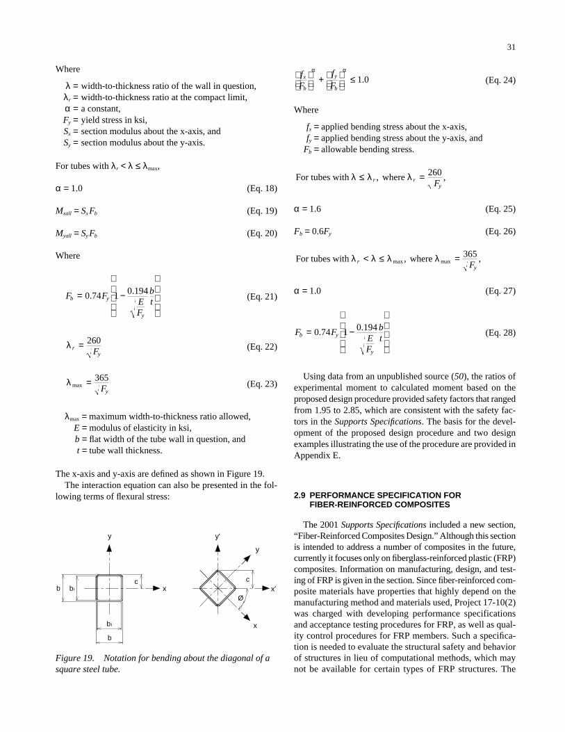
Where
λ = width-to-thickness ratio of the wall in question,λr = width-to-thickness ratio at the compact limit,α = a constant,Fy = yield stress in ksi,Sx = section modulus about the x-axis, andSy = section modulus about the y-axis.
For tubes with λr < λ ≤ λmax,
α = 1.0 (Eq. 18)
Mxall = SxFb (Eq. 19)
Myall = SyFb (Eq. 20)
Where
(Eq. 21)
(Eq. 22)
(Eq. 23)
λmax = maximum width-to-thickness ratio allowed,E = modulus of elasticity in ksi, b = flat width of the tube wall in question, andt = tube wall thickness.
The x-axis and y-axis are defined as shown in Figure 19.The interaction equation can also be presented in the fol-
lowing terms of flexural stress:
λ max = 365Fy
λ ryF
= 260
F FEF
btb y
y
= −
0 74 1 0 194. .
31
(Eq. 24)
Where
fx = applied bending stress about the x-axis,fy = applied bending stress about the y-axis, and
Fb = allowable bending stress.
α = 1.6 (Eq. 25)
Fb = 0.6Fy (Eq. 26)
α = 1.0 (Eq. 27)
(Eq. 28)
Using data from an unpublished source (50), the ratios ofexperimental moment to calculated moment based on theproposed design procedure provided safety factors that rangedfrom 1.95 to 2.85, which are consistent with the safety fac-tors in the Supports Specifications. The basis for the devel-opment of the proposed design procedure and two designexamples illustrating the use of the procedure are provided inAppendix E.
2.9 PERFORMANCE SPECIFICATION FORFIBER-REINFORCED COMPOSITES
The 2001 Supports Specifications included a new section,“Fiber-Reinforced Composites Design.” Although this sectionis intended to address a number of composites in the future,currently it focuses only on fiberglass-reinforced plastic (FRP)composites. Information on manufacturing, design, and test-ing of FRP is given in the section. Since fiber-reinforced com-posite materials have properties that highly depend on themanufacturing method and materials used, Project 17-10(2)was charged with developing performance specificationsand acceptance testing procedures for FRP, as well as qual-ity control procedures for FRP members. Such a specifica-tion is needed to evaluate the structural safety and behaviorof structures in lieu of computational methods, which maynot be available for certain types of FRP structures. The
F FEF
btb y
y
= −
0 74 1 0 194. .
For tubes with where λ λ λ λryF
< ≤ =max max, ,365
For tubes with where λ λ λ≤ =r ryF
, ,260
fF
fF
x
b
y
b
+
≤α α
1 0.
b
bi
b
y
bic c
xØ
y'
x
y
x'
Figure 19. Notation for bending about the diagonal of asquare steel tube.

main sections of the proposed performance specificationinclude the following:
• Determination of bending strength for FRP poles;• Determination of torsional strength for FRP poles;• Determination of fatigue strength for FRP poles;• Properties of raw materials, such as polyester resin and
glass fiber reinforcement;• Specification of protective materials, such as coatings or
veils, which are required to protect against weathering,solar ultraviolet rays, and wind abrasion; and
• Deflection criteria.
2.9.1 DOT Survey and Documents Reviewed
A survey of all state DOTs was conducted to gather infor-mation on the use of fiber-reinforced composite (FRC) andperformance specifications for FRC structures. According tothe survey, 19% of the state DOTs use or have used FRC struc-tures, and 81% of the state DOTs do not use or have not usedFRC structures. When the state DOTs were asked whetherthey have specifications or acceptance testing procedures forFRC structures, 2% responded yes, 2% responded no, and96% responded not applicable. Considering the state DOTsthat use or have used FRC, the major applications are streetlighting (67%), roadside signs (11%), and other structures(22%). In summary, the results of the survey indicate thatFRP is mainly used for lighting poles and roadside supports.The survey also revealed that very few states have specifica-tions for FRP structures.
The most updated literature on FRC testing and designwas studied and evaluated. Special emphasis was put on testmethods and performance evaluation of FRP members, aswell as existing specifications for FRP lighting poles. Themajor references reviewed included the following:
• ASTM D4923-01, “Standard Specification for Rein-forced Thermosetting Plastic Poles” (51);
• NCHRP Report 411: Structural Supports for HighwaySigns, Luminaires, and Traffic Signals (1);
• Structural Design of Polymer Composites—EurocompDesign Code and Handbook (52);
• British Standard BD26/94, “Design of Lighting Col-umns” (53);
• ANSI C136.20, Fiber-Reinforced Plastic (FRP) Light-ing Poles (54);
• Caltrans Standard Special Provision 86.08.5 and Cal-trans Test 683 (55);
• City of Seattle Standard Specification 8-32: Poles,Pedestals and Foundations (56);
• Carolina Power and Light Company, Group Specifica-tion GS-32 for Fiberglass Post (57);
• Illinois Power Company, Material Specifications forFiberglass Street Lighting Poles (58);
32
• Newmark International, Inc., Specification for Fiber-glass Reinforced Composite Poles (59);
• Shakespeare Company, Shakespeare Composite UtilityPole Specifications (60);
• Southern California Edison Company, SpecificationMS32-1995, Fiberglass Reinforced Plastic Street Light-ing Electroliers (61);
• Southern Company, Fiberglass Lighting Pole Specifi-cations (62);
• Hawaii DOT, Special Provisions, Specifications, Pro-posal and Contract for Furnishing and Delivering StreetLight and Traffic Signal Poles, Arms, Bases, Luminairesand Cable (63);
• Pacific Gas and Electric Company, Specification for Non-Wood Distribution Poles (64);
• Public Service Company of New Mexico, PNM Speci-fication SL2 Revision 3: Aluminum/Fiberglass LightingPoles (65);
• ASTM G154-00a, “Standard Practice for OperatingFluorescent Light Apparatus for UV Exposure of Non-Metallic Materials” (66); and
• ASTM D635-98, “Standard Test Method for Rate ofBurning and/or Extent and Time of Burning of Plasticsin a Horizontal Position” (67).
FRP manufacturers were contacted regarding quality con-trol procedures and performance specifications. Manufactur-ers that were contacted included Newmark International,Inc.; the Shakespeare Company; Strongwell Corporation; andValmont Industries, Inc. Utility companies that have devel-oped performance specifications for FRP lighting poles werealso contacted, and their specifications were obtained andreviewed.
The proposed performance specification for FRP lightingpoles was developed using the information gathered fromstate DOTs, FRP pole manufacturers, and utility companies’specifications. Special effort was made to produce a specifi-cation that is general in nature with provisions that are inde-pendent of manufacturer and manufacturing method.
2.9.2 Performance Specifications andAcceptance Testing Procedures
The 2001 Supports Specifications includes a method forthe evaluation of bending performance of FRP poles basedon full-scale testing. The method presented is based on ASTMD4923-01, with modifications for safety factors according toANSI C136.20. The current Supports Specifications does notaddress torsional strength and fatigue performance, but it ref-erences ASTM D4923-01 for provisions on those topics. Also,the Supports Specifications does not include provisions for theevaluation of weathering performance for FRP members.
The proposed performance specification for FRP lightingpoles includes provisions for performance verification by test-ing. Tests include bending, torsion, fatigue, and weathering

exposure. It also includes construction requirements, qualitycontrol, and acceptance criteria for FRP poles. The pro-posed performance specification is presented in a side-by-side specification/commentary format in Appendix F. Perti-nent sections of the proposed performance specification arebriefly discussed herein.
2.9.2.1 Design Loads
The proposed performance specification for FRP lightingpoles references the 2001 Supports Specifications for the eval-uation of the gravitational and environmental loads applied tothe poles to ensure that the structural capacity of FRP polesmatch or exceed the load requirements prescribed by the 2001Supports Specifications.
2.9.2.2 Deflection Limits
The lateral deflections limits proposed by the performancespecification for FRP lighting poles are as follows:
• 15% of the pole height for lateral deflection under designdead-plus-wind loads (maximum deflection),
• 30-mm/m (0.35-in/ft) maximum slope at top of the poleunder dead load from arm and attachments (maximumslope), and
• 5% of the pole height for lateral deflection under an890-N (200-lb) lateral top load (stiffness requirement).
The lateral deflection is measured from the deflected tip endof the pole along a line perpendicular to the longitudinal axisof the undeflected pole. The maximum deflection limit consti-tutes a safeguard against highly flexible structures, whereas themaximum slope limit is a serviceability requirement for aes-thetic considerations. These two limits are equivalent to thedeflection limit requirements of Section 10.4.2.1 of the 2001Supports Specifications. The stiffness requirement is intendedto ensure that the pole does not deflect excessively when main-tenance workers use ladders to access attachments located atthe top of the pole.
2.9.2.3 Bending Test
The provisions for the performance evaluation of FRPpoles in bending are based on ASTM D4923, with the fol-lowing modifications:
• The safety factor against failure in bending is 2.0, whichaccounts for the variability of materials and perfor-mance often found in FRP products from different man-ufacturers and different production methods.
• When testing FRP poles with hand holes, the hand holeshould be placed on the compression side of the pole, andthe hand hole cover should be removed during testing.
33
• Deflections should be recorded with each 223-N (50-lb)load increment.
• The maximum acceptable permanent deflection aftertesting should not exceed 2% of the maximum deflec-tion of the pole during the test. This deflection shouldbe recorded 5 minutes after unloading.
The safety factor of 2.0 against failure in bending is greaterthan the safety factor of 1.5 specified by ASTM D4923. Thisadditional safety accounts for the variability in mechanicalproperties of FRP. It also reflects the consensus of the safetyfactors among different FRP specifications reviewed andmatches the bending safety factor requirements of ANSIC136.20.
2.9.2.4 Torsion Test
The provisions for the performance evaluation of FRPpoles in torsion are based on ASTM D4923, with the fol-lowing modifications:
• The safety factor against failure is 2.0.• Specification of the load increments during testing is
223 N (50 lb), with deflections recorded at each loadincrement.
A safety factor of 2.0 against failure in torsion is used inorder to match the safety factor used against bending failure.
2.9.2.5 Fatigue Test
The provisions for the fatigue performance evaluation ofFRP poles are based on ASTM D4923, with the followingmodifications:
• Bending or torsional fatigue loads applied to the polecorrespond to an equivalent wind pressure of 110 Pa(2.3 psf). (Note: The use of a wind pressure eliminatesthe dependence on wind speed for pressure computationsfor fatigue, since the formulations for wind pressure inthe 2001 Supports Specifications have changed from afastest-mile wind speed to a 3-second gust approach).
• Fatigue loads are applied for 106 cycles, with no morethan 200 cycles per minute.
• Destructive testing of the pole for bending and/or tor-sion strength should be performed after application offatigue loads.
2.9.2.6 Weathering Performance
The provisions for the weathering performance evaluationof FRP poles require that the surface of the pole be exposed toa minimum of 2,500 hours of accelerated weathering accord-ing to ASTM G154. The proposed specification requires the

use of UV-B lamps with 313-nm wavelength and a testingcycle of 4 hours of UV exposure at 60 degrees Celsius and4 hours of condensation at 50 degrees Celsius. UV-B 313lamps produce the shortest wavelengths found in sunlight inthe surface of the earth. This particular type of sunlight isknown to be responsible for considerable polymer damagecapable of affecting the mechanical performance of FRP poles.
After testing, the finished surface shall not exhibit fading,fiber exposure, chalking, cracking, or crazing. The weatheringperformance requirements are based on the weathering provi-sions of Caltrans 86.08.5 and Hawaii DOT HWY-C-06-98.ASTM standard G53 (68), originally referenced by the 2001Supports Specifications for the evaluation of weatheringresistance of FRP poles, was replaced by ASTM standardG154 in 2000.
2.9.2.7 Flame Resistance
FRP poles should be flame resistant in order to avoid prop-agation of fires induced by short circuits or fuel spills. Theproposed performance specification for FRP poles requiresthat specimens tested for flame resistance according to ASTMD635 be manufactured with the same materials and identicalmanufacturing process as the actual poles. The specimens areconsidered flame resistant if they cease to burn before thegauge mark of 3.94 inches (100 mm) is reached. This require-ment is adopted from the Hawaii DOT HWY-C-06-98 andalso reflects the general consensus of flame resistance require-ments among other specifications reviewed.
2.9.2.8 Fabrication Details
The proposed specification for FRP lighting poles containsprovisions for construction of FRP poles. Those provisionsinclude surface protection, finish, wiring access, hand holes,and pole caps. The construction provisions include suggestedvalues of burial depth for direct-burial poles and suggestedvalues of bolt circle for base-mounted poles according toANSI C136.20. For direct-burial poles, the proposed specifi-cation for FRP lighting poles requires an antirotation deviceto prevent rotation of the pole and enhance lateral stabilityfor wind loads.
2.9.2.9 Quality Control and Acceptance Criteria
The proposed performance specification contains a set ofprovisions on quality control and acceptance criteria for FRPmaterials. Those provisions specify that the manufacturer mustsubmit detailed technical information about the proposedproduct for approval prior to production. The submitted tech-nical information should include samples of the manufacturedproposed product, stating clearly the kind and quality of thefibers and resin used in the composite. This is required because
34
the structural properties of FRP members are highly depen-dent on the type and quality of glass fibers and resins used,as well as the manufacturing process. The new provisions onquality control also include requirements for storage andshipping of finished FRP products to prevent damage prior toinstallation.
2.9.3 Summary
A proposed performance specification was developed forFRP poles based on input from DOTs, FRP pole manufac-turers, and the review of electric utility companies’ specifica-tions. The proposed performance specification covers accep-tance testing procedures for FRP, including bending, torsion,fatigue, weathering testing, and limits on deflections. Fab-rication requirements, flame resistance, and quality controlof materials and finished product are also covered. The pro-posed performance specification for FRP lighting poles ispresented in a side-by-side specification/commentary formatin Appendix F.
2.10 INSPECTION, RETROFIT, REPAIR, AND REHABILITATION OF FATIGUE-DAMAGED SUPPORT STRUCTURES
The objective of this work was to address inspection, repair,retrofitting, and rehabilitation of fatigue-damaged supportstructures. A separate report prepared to address these issuesis provided in Appendix G. A brief summary of the findingsof that report is given herein.
A survey was sent to all state DOTs to determine whichstates repair fatigue-damaged support structures. The survey(presented in Appendix A) revealed that 26% of states thatresponded have repaired fatigue-damaged structures. How-ever, only Michigan has developed a maintenance plan, pro-cedures, or manual for retrofit and rehabilitation of sign sup-port and luminaire structures. Contacts were made with stateDOTs that indicated knowledge of repair to fatigue-damagedstructures. The research team met with the investigators ofNCHRP Project 10-38 and visited a local sign support man-ufacturer. The research effort included a comprehensivereview of available relevant literature.
2.10.1 Fatigue Cases
State DOTs were contacted to collect information on fatigueproblems that have been encountered. Documentation for onlya few fatigue cases was found in the form of memorandumsand internal reports. These cases were reviewed and are pre-sented in the report. The cases found include fatigue crackingof support structures in Michigan, Wisconsin, and Wyoming.Cracks due to galvanizing that were observed in a visit to alocal sign support manufacturer are also discussed.

2.10.2 Inspection
Relevant literature was reviewed. State DOT offices andFHWA engineers were contacted to gather additional infor-mation about the methods used for inspection of supportstructures. The report presents inspection procedures for high-mast luminaires and sign support structures and summarizesmethods of weld inspections.
2.10.3 Repair and Rehabilitation Procedures
Relevant literature was reviewed. NCHRP Report 206:Detection and Repair of Fatigue Damage in Welded High-way Bridges (69) was studied in detail. The various tech-niques used to extend the fatigue life are summarized, anddescriptions of repair methods for specific fatigue cases areillustrated.
2.10.4 Vibration Mitigation Methods
Vibration mitigation devices can be used to reduce theloads that cause fatigue and extend the life of the structure.The most effective type of mitigation depends upon the typeand direction of wind loading phenomena causing vibration.The latest information that could be obtained from NCHRPProject 10-38 and 10-38(2) regarding vibration and mitigationdevices was reviewed and included in the appendix. Thesedevices include commercially available dampers such as theHapco and Alcoa dampers, along with new configurationssuggested by NCHRP Project 10-38(2) such as the strut andliquid-tuned dampers. A complete evaluation of the methodsavailable to mitigate fatigue-induced effects is included in thefinal results of NCHRP 10-38(2).
2.11 STRATEGIC PLAN FOR FUTURESUPPORTS SPECIFICATIONSENHANCEMENTS
The 2001 AASHTO Supports Specifications was a directresult of the extensive research work performed underNCHRP Project 17-10. Although the work on this projectwas initiated in 1995 and completed in 1997, the 2001 Sup-ports Specifications was published in summer 2001. NCHRPProject 17-10(2) was initiated in 1999 to address further issuesfor the refinement of the Supports Specifications. Results ofNCHRP Project 17-10(2), as well as future enhancements,must be implemented in the Supports Specifications in orderto keep the document the most current and up to date. Thissection provides an outline of a strategic plan for enhancingthe Supports Specifications and maintaining its currency inthe future.
35
2.11.1 Introduction
The Supports Specifications is the main document for thedesign of structural supports in the United States. It governsthe design, construction, and safety of the various types ofstructural supports and is currently adopted by all state DOTsand by other agencies. Although the 2001 edition has just beenpublished, several revisions have already been identified andare ready for inclusion in the specifications. Also, revisionswill be necessary to integrate the results of NCHRP Projects17-10(2) and 10-38(2), updates in material or load specifica-tions referenced by the Supports Specifications, and other tech-nical information that will be developed in the future. There-fore, a mechanism for making changes and upgrades on aregular basis is needed in order to efficiently manage the doc-ument in the future.
The information in the 2001 Supports Specifications iscomprehensive in nature. It incorporates several new engi-neering concepts, design criteria, structure types, and mate-rials. Additionally, as new information becomes availablethrough research and practice, consideration should be givenfor incorporating this new information in the specifications.As such, it will be difficult to maintain the specifications andtheir state-of-the-art features using solely committee volun-teer effort. A plan is needed that will outline a mechanism bywhich the Supports Specifications will be regularly updated,maintained, and published in a timely manner.
Furthermore, it was recommended by NCHRP Project 17-10 in1995 to revise the Supports Specifications using an allowablestress design (ASD) approach. This decision was primarilybased on the lack of vital information necessary to establish arational LRFD approach and on the fact that the existing ASDspecifications at that time had not been revised for a num-ber of years and contained several deficiencies that neededupgrading. It was therefore recommended to bring the speci-fications to an up-to-date ASD format that would be easilyupgradeable to an LRFD approach in the future.
2.11.2 Conversion to an LRFD Philosophy
2.11.2.1 Problem Statement
The 2001 Supports Specifications adopts an ASD approachand format. However, the recent trend for most design specifi-cations—including the AASHTO LRFD Bridge Design Spec-ifications, AISC Manual of Steel Construction, and the Alu-minum Design Manual—is to adopt an LRFD method. Themove toward adopting LRFD is due to the more consistentapproach that the method provides with respect to strengthevaluation and structural safety. An LRFD Supports Specifi-cations would also be easier to incorporate future engineer-ing developments and test information into, since the speci-fications derives much of their information from nationalspecifications that are based on LRFD. LRFD will greatlyfacilitate updates to the Supports Specifications as material
specifications evolve or new materials emerge. Engineerswould also benefit from a unified design approach that is con-sistent with other commonly used design specifications andsimpler to apply. Hence, converting the Supports Specifica-tions to an LRFD philosophy and format is highly recom-mended for the next major update of the document.
2.11.2.2 LRFD Philosophy
The LRFD methodology is primarily based on the follow-ing equation:
Σ γi Qi ≤ φRn (Eq. 29)
Where
γi = load factor, a statistically based multiplier applied toforce effects;
φ =resistance factor, a statistically based multiplier appliedto nominal strength;
Qi = force effect; andRn = nominal resistance.
The factors that are applied to loads and resistance are theintended safety factors that account for uncertainties associ-ated with the loads, materials, and various design assump-tions. The main characteristic of the LRFD philosophy is thatit provides a consistent approach to strength evaluation andstructural safety. The approach takes into account the vari-ability in the behavior of structural elements and accounts forsafety in a more rational way. The LRFD method assigns dif-ferent overload factors γi to loads depending on the type ofload and on the factored load combination that must be con-sidered. The resistance factor φ is another safety-related pro-vision, which accounts for the type of member, material, andlimit state considered. Those two factors could be adjusted toensure more uniform reliability in the design.
Although literature on LRFD is available for differentmaterials, the application of the method to support structurescannot be achieved by simply adopting the load and resis-tance factors implemented in other specifications. Probability-based studies and calibrations with ASD are needed to estab-lish the load and resistance factors pertaining to supportstructures. Adding to the complexity of the needed work forestablishing an LRFD specification is the wide range of mate-rials, including fiber-reinforced composites, that are coveredby the specifications.
The development of the LRFD method is based on the fol-lowing main considerations:
• Probability-based model,• Calibration with the allowable stress specifications,• Judgment and past experience, and• Comparative design studies of representative structures.
36
The LRFD approach requires that a procedure be availableto determine values for the resistance factors and the loadfactors. For a structural member or element designed accord-ing to current specification, it is possible to compute the rel-ative reliability of this design from data defining probabilitydistribution and statistics of the resistance, loads, and loadeffects. The relative reliability is expressed as the reliabilityindex. By repeatedly determining the reliability index formany structural designs, the relative reliability of differentstructural members built from different structural materialscan be compared. For a selected value of the reliability index,using reliability analysis methods, it is possible to computethe resistance and load factors. The process is elaborate andrequires a considerable amount of work, especially if newstructural materials are investigated.
Hence, to adopt an LRFD approach for support structures,an extensive study is needed to develop the load and resistancefactors pertaining to this category of structures. Probability-based studies, considering the variables involved in the designof different categories of support structures, may result indesign parameters that differ for each category of structures.Experimental studies may also be needed to establish reliablestrength equations for emerging materials or for special shapesused extensively for support structures.
2.11.2.3 Reliability-Based Design Approach
The LRFD method is a probability-based design method,involving predicting the probability that loads imposed on astructure or member would cause the structure or member tocease its intended function. Load factors are developed toaccount for uncertainties in estimating dead and live loads.Resistance factors are developed to account for uncertaintiesin material strengths, dimensions, and quality of construction.In order to develop load and resistance factors for supportstructures, a statistical study is needed to simulate variationsin materials and loadings that are unique to support structures.Variations in resistance of typical materials and shapes wouldneed to be studied, as well as variations in loadings.
The variations can be simulated using the Monte Carlomethod, which generates random numbers to evaluate a func-tion containing several variables expressing the scatter of mate-rial properties, physical dimension variations, and extremeloadings. The values are mapped to a resulting frequencydistribution that allows for the probability of exceedance to bedetermined.
The variation in resistance can be determined by usingMonte Carlo simulations. Statistics must be generated for limitstates for support structures. The term limit state describes acircumstance where a structure or one of its components doesnot perform its intended function in terms of strength or ser-viceability. Statistical information on variations in materialproperties and physical dimensions of structural shapes isobtained. Individual variations in material properties and phys-ical dimensions are combined to provide a probable resis-

tance (e.g., bending moment, shear strength, tensile strength,compressive strength) for a particular structural shape.
The variation in loading can also be determined usingMonte Carlo simulations. Statistical data on loadings will needto be reviewed in the context of support structures, especiallystatistics on extreme wind load effects on support structures.These extreme wind-load-effect statistics may be generatedusing Monte Carlo simulations. In addition, the most signif-icant load ratios for support structures will need to be deter-mined. These load ratios will be much different for supportstructures than for building or bridge structures.
Reliability is the percentage of times that the strength of astructure will equal or exceed the maximum loading appliedduring the structure’s estimated life. Reliability indexes indi-cating the reliability associated with the Supports Specifi-cations will be determined using the statistical informationgenerated on resistance and loadings. These indexes will bedetermined using the advanced first-order, second-moment(AFOSM) method. Then the AFOSM method will be used todetermine load and resistance factors for support structuresthat optimally achieve the reliability overload ratios associ-ated with these structures. The calibration procedure that isrequired to establish load and resistance factors involves thefollowing steps:
1. Select typical structures.2. Establish a statistical database for load and resistance
parameters.3. Develop load and resistance models.4. Develop a reliability analysis procedure.5. Select a target reliability index.6. Calculate load and resistance factors.
Proper implementation of an LRFD method, which pro-vides appropriate load and resistance factors that are specificto support structures, will lead to a more consistent approachto strength evaluation and structural safety than any otherdesign approach will. Support structures will be designed forthe same reliability regardless of the material used. The spec-ifications will be consistent with other nationally recognizedspecifications; this consistency will facilitate future updatesof the document. Engineers will also benefit from a unifieddesign approach that is rational and compatible with otherdesign specifications.
2.11.2.4 Step-by-Step Procedure for theDetermination of Load and ResistanceFactors
The literature has abundant information on methods andprocedures used to convert design specifications to LRFDapproach. Much of this information has been previouslyreported by NCHRP Project 17-10 (1). Extensive work hasalso been performed in converting the bridge specificationsinto an LRFD philosophy (7, 70, 71). The work involved the
37
development of load and resistance models, selection of thereliability analysis method, and calculation of the reliabilityindexes. This work can serve as a model in converting theSupports Specifications to an LRFD philosophy. However, itshould be noted that structural supports substantially differfrom bridge structures in many aspects, and these differencesmust be considered in the conversion process. The low redun-dancy, high structure flexibility, predominance of wind load-ing, and susceptibility to wind vibrations are only a few ofthe characteristics of structural supports that must be consid-ered in the LRFD model to ensure correct prediction of struc-tural performance.
A general procedure for the calculation of the load andresistance factors for the Supports Specifications may be out-lined as follows:
1. Selection of representative structures. A large num-ber of structural supports will be selected for analysisfrom various geographical regions of the United States.The structures will represent the different support types,materials, and configurations. The selection will focuson the typical structures that are commonly used in dif-ferent parts of the United States.
2. Establishing a statistical database for the load pa-rameter. Data on the different type of loads pertinentto support structures will be gathered. Updating theSupports Specifications for the most recent wind loadsand map will also be part of this work. The statisticalmodel of load, Q, will include the cumulative distribu-tion function (CDF) and/or the mean, bias, and coeffi-cients of variation of the load derived using the back-ground information for wind and other loads in theSupports Specifications.
3. Establishing statistical data for the resistance para-meter. Statistical data related to the materials used forsupport structures will be gathered. These data includematerial tests, component tests, and field measurements.
4. Formulation of strength limit states. Strength limitstates for the various components of support structureswill be formulated, and the basic parameters of resis-tance needed for those limit states will be identified.This step will involve considering the various strain-ing actions (axial force, bending, shear, etc.) and thetypes of structural member that are commonly appliedto structural supports (e.g., multisided shape, roundtube, and I-shaped). This step is particularly importantfor new materials where strength limit states have notbeen formulated.
5. Development of the resistance model. Resistance mod-els will be developed for the different structural materi-als, components, and limit states identified in Step 4.The most current LRFD specifications for the differentmaterials will be used as the basis for the derivation ofthe resistance models. For new materials, such as fiber-reinforced composites, the most recent literature infor-mation will be used as the basis for the proposed strength

equations. Other factors such as ductility and durabilitywill also be considered in the resistance model.
The statistical model of resistance, Rn, will includethe CDF and/or the mean, bias, and coefficients of vari-ation of the resistance derived using the available sta-tistical database of Step 2.
6. Selection of the target reliability index. The reliabil-ity index, β, will be calculated for a wide spectrum ofreal support structures designed according to the 2001Supports Specifications, as well as structures designedaccording to earlier versions of the Supports Specifica-tions. This calculation is particularly necessary, sincethe 2001 specifications have just been published anddocumented experience using this specification is notavailable. A target reliability index, βT, will be selectedto provide a consistent and uniform safety margin forall materials. The target reliability index may vary fordifferent types of support structures depending on theimportance of the structure and the intended level ofsafety. Care should be taken in selecting the target reli-ability for the different support structures. For example,the AASHTO LRFD Bridge Design Specifications (7)adopts a value of 3.5; however, arbitrarily adopting thisvalue could result in very conservative designs anduneconomical support structures.
7. Reliability analysis. Reliability is measured in termsof the reliability index, β, which is a measure of struc-tural performance. Once a target reliability index, βT,has been selected, the calibration of load factors andresistance factors to achieve approximately the value ofthe target reliability may proceed using an iterative pro-cedure as described by Nowak (70, 71). A larger num-ber of hypothetical support structures with variations indesign parameters will be used in the calibration process.
8. Selection of the load and resistance factors. Loadfactors, γi, will be calculated so that the factored loadshave a predetermined probability of being exceeded.Resistance factors, φ, are calculated so that the struc-tural reliability is close to the target value, βT.
Experimental work may be needed if only limited data canbe found for certain materials. Fiber-reinforced compositesare an example where structural testing may be required todevelop strength equations.
A less rigorous alternative to conducting the full calibra-tion described above is using a confidence limit approach. Inthis case, the resistance factor, φ, would be selected such thatthe 95th percentile resistance is achieved. This approach couldprovide quick results and interim data until full calibrationcould be performed.
2.11.2.5 Time and Cost Estimates
It is estimated that this project will cost approximately$500,000 and be performed over a 30-month period.
38
2.11.3 Future Enhancements
Technical topics that need to be investigated for furtherimprovement of the Supports Specifications are given hereinwith a brief description of each topic.
2.11.3.1 LRFD Conversion
Details related to the work needed to convert the specifi-cations to an LRFD philosophy and format are given in Sec-tion 2.11.2. It is highly recommended that subsequent edi-tions of the 2001 Supports Specifications adopt an LRFDapproach. Since the 2001 specifications offer the most cur-rent ASD information, it is prudent to begin the conversionprocess immediately.
2.11.3.2 New Wind Map and Wind Provisions
The proposed Supports Specifications is based on infor-mation in ASCE 7-95. ASCE 7-98, Minimum Design Loadsfor Buildings and Other Structures, has just been published.The ASCE 7-98 standard should be reviewed for updates thatcould be applicable to the Supports Specifications wind load-ing criteria. Important considerations in the newly publishedASCE 7-98 document include the load factor for wind, a winddirectionality factor, and changes in the hurricane contours onthe wind map.
2.11.3.3 Structure Design Differences Betweenthe 1994 and 2001 SupportsSpecifications
Perform a study to compare design differences that occuron an overall structure level between the 1994 and 2001specifications. This study would encompass major designevaluations of typical support structures across the country.The design examples developed as part of NCHRP Project17-10(2) would be used as a starting point for the designcomparisons. The study will also investigate the effect of dif-ferent load types (wind, fatigue, etc.) in controlling the designof the structure. This would considerably simplify the designcalculations and provide the designer with better understand-ing of the intent of the specifications.
2.11.3.4 Fatigue and Vibration
Although a survey was distributed to all state DOTs andmany persons were contacted for additional information, thequestion of whether noncantilevered sign support structuresare susceptible to fatigue from galloping and vortex sheddinghas not been assertively answered. There is need for addi-tional investigation in this regard by (a) additional contactsand review of failure cases and (b) laboratory and field testing/

monitoring. Research is needed to evaluate the dynamicbehavior of existing support structures that exhibit fatigueand/or vibration problems. This research should include mon-itoring displacement amplitudes, calculating stresses in thecritical connections, and comparing the response with thestatic loads recommended in this research.
Several states have attributed problems to fatigue fromexcessive vibration, but these cases really were not analyzedto determine which type of wind loading is causing the prob-lem. A uniform inspection procedure used by various statesto help them accurately determine the cause of the fatigueproblem would be useful. A database or collection of datacould then be analyzed. Such information as the vibrationamplitude and direction, wind speeds, and uniformity of thewinds would be needed.
Regarding deflection limits, a range of noncantilevered sup-port structures was checked against the current L/150 require-ment (where L equals the span of the structure), and all of thestructures analyzed met the requirement. However, the L/150requirement was really developed for checking stiffness ofmonotube structures. Further study is needed to determineif the L/150 is really appropriate for noncantilevered trussstructures.
Based on the assumption that noncantilevered sign supportstructures are susceptible to the same vibration phenomena ascantilevered support structures, the finite element method wasused to determine whether the fatigue loads recommendedfor cantilevered sign support structures are appropriate fornoncantilevered structures. Recommendations were made.However, the impact of the recommendations on design wasnot evaluated. Before the recommendations are adopted, theeffect of the recommendations should be evaluated in termsof increasing weight, geometry, cost, etc.
2.11.3.5 Categorization of Fatigue ConnectionDetails
The research team developed recommendations regardingcategorization of connection details for noncantilevered sup-port structures by reviewing (a) the categorization alreadyadopted for cantilevered sign support structures and (b) con-nection categorization used for bridge design. Actually, thecategorization adopted for cantilevered sign support struc-tures was developed by reviewing bridge connection cate-gories, plus very limited testing. There is need to conduct addi-tional fatigue testing of typical sign support structure detailsto categorize connection details accurately.
2.11.3.6 Vibration Mitigation Methods
Available information from NCHRP Project 10-38(2)regarding effectiveness of vibration mitigation methods wassynthesized. It appears that the effectiveness of such vibra-tion mitigation methods is being measured in terms of reduc-
39
tion in displacement amplitude and reduction in vibrationduration after the load vanishes (i.e., truck wind gusts). Thecurrent research appears to be limited to cantilevered supportstructures. The research team’s colleagues have also indi-cated their idea regarding how much of a fatigue load reduc-tion can be accounted for if mitigation devices are used.Additional research is needed to demonstrate the effective-ness of vibration mitigation devices in terms of stresses andto relate the effectiveness to reduction in fatigue designloads. A range of support structure configurations should beincluded. Also, the final results of NCHRP Project 10-38(2)need to be included.
2.11.3.7 Variable Message Signs
Variable message signs (VMSs) have been introduced inthe past few years. Since their introduction, their use hasbeen increasing rapidly and their design and configurationare constantly changing. VMSs have dimensions, configura-tions, and weights that differ significantly from those of usualsigns and thus could highly impact the design of the sup-porting structure. Current VMS sizes have reached 36 feetlong by 12 feet high by 41/2 feet deep, with a weight exceed-ing 5,000 pounds. The current Supports Specifications doesnot address VMSs or their supporting structures. With theincreasing use of VMSs, it is imperative that future versionsof the Supports Specifications include guidance and provi-sions for the design of VMS supporting structures and theirfoundations.
Two failures of VMS supporting structures have beenreported. One case was in Virginia where the sign was attachedand supported by a cantilever structure. Another case wasin California where a Caltrans 18-inch monotube structuralsupport that was designed to carry a VMS failed at a fatigue-generated crack just above the weld at the base plate. Spe-cific design considerations should be developed to guide thedesigner and ensure safer designs in the future.
VMSs are heavier and much larger than normal signs are.VMSs are attached to the supporting structure in such a man-ner that torsional loads become significant. Because of thesize of VMSs, the effects of the aerodynamic forces areimportant and must be carefully evaluated. Truck-inducedwind gusts and vortex shedding cause vibrations and fatigue.The presence of the torsional loads compounds the vibrationand deflections induced by the wind and aerodynamic forces.The connection or method of attaching the VMS to the sup-port structure is also important and must be addressed by theengineer.
Although the current AASHTO Supports Specificationsdoes not address VMSs or their supporting structures, engi-neers have erroneously used the current Supports Specifica-tions in the design of such structures. The VMS was treatedas a normal thin and flat sign. This treatment could result infaulty designs, since several of the provisions of the currentSupports Specifications may not directly apply to structures
supporting VMSs. For example, the section on wind loads inthe current Supports Specifications contains information thatwas developed mainly for wind pressures acting on thin flat-faced signs, not VMS. The wind pressure, drag coefficients,and uplift forces must be revised to account for the VMSstructures that are much larger in size (structures that couldhave a roof of 4 to 5 feet and a bottom of 3 to 4 feet).
Additional design information is needed in order for theengineer to design safe and economical VMS structures.Both theoretical and field studies are needed to document thebehavior of the VMS structures and to develop guidelines fortheir proper design and construction. Information on theeffects of high torsional loads in combination with dead andlive loads must be evaluated. Complex aerodynamic forcesfrom wind and moving traffic as a result of the large physi-cal dimensions of the sign warrant careful evaluation. Theinduced movements and vibrations cause fatigue and couldbe detrimental to the sensitive electronic equipment of theVMS. Wind tunnel tests are needed to develop the necessaryinformation on wind pressure and drag coefficients. Ice loadsshould be investigated, and water ponding on the flat surfacesshould also be taken into consideration. The method of con-necting the VMS to the supporting structure is an importantdesign consideration. The center of gravity of the VMS isusually placed off the centerline of the horizontal support.This placement can produce significant torsional loads anddeflections. The VMS could be integrated in the supportingtruss structure to eliminate such torsional loads. Foundationdesign requirements must also be reviewed in light of thelarger loads that are transmitted in this case. Finally, it shouldbe useful to develop a mechanism for interaction where theanalysis and design efforts of the engineer/fabricator of theVMS and the engineer/fabricator of the support structure arecoordinated in order to achieve a safe and economical design.
2.11.3.8 Bridge-Mounted Signs
There has been a tendency to place large signs and signswith maintenance walkways on bridges in lieu of adding anadditional structure, either as an effort to save money orbecause of utilities or drainage that conflict with foundationsfor structures. However, these structures are difficult to fab-ricate and construct, as well as significantly higher in cost.Potential problems and safety hazards may arise if such struc-tures are used without adequate attention to special designconsiderations. The current specifications provide no infor-mation on the design of sign structures connected to bridgestructures.
Research is needed to investigate the important issuesregarding the design and construction of bridge-mountedsigns, and the information gained should be incorporated intothe Supports Specifications. At a minimum, the followingissues should be investigated:
40
• The effect of sign loads on existing bridge girders;• The effect of vibration and deflection of bridge girders
on the members that support the signs and maintenancewalkways;
• Forces at connections to the bridge girders and bridgedeck (and guidelines on acceptable methods of connect-ing to steel and prestressed concrete girders, concreteslab, and parapet walls);
• The need for DOTs to furnish complete and up-to-dateinformation regarding the bridges to which these struc-tures are connected, along with project documents;
• Requirements for verifying the adequacy of an existingbridge to support bridge-mounted signs;
• Guidelines on design responsibilities (i.e., who is respon-sible for what part of each design);
• The issue of whether specifications should prohibitmounting VMSs directly to bridge girders; and
• Cost comparisons of bridge-mounted structures versuscantilever or span structures.
2.11.3.9 Strength of Fiber-Reinforced CompositeSupport Structures
The use of fiber-reinforced composite, especially fiberglass-reinforced plastic (FRP), as support structures is rapidlyincreasing. The FRP products, however, have varying phys-ical properties that depend on the materials and fabricationmethod used. No design specifications or codes are cur-rently available that cover the design requirements for FRPstructures.
An experimental program is needed to evaluate the strengthproperties of cross-sectional shapes typically used for sup-port structures and to verify the strength equations given inthe 2001 Supports Specifications. The study should focus oncommonly used materials, namely polyester resin and glassfiber reinforcement. Products from the three major manu-facturing methods (i.e., pultrusion, centrifugally casting, andfilament winding) should be considered. For each of the man-ufacturing methods, the testing program should include sev-eral parameters, such as cross-sectional shape, fiber orienta-tion, glass-resin ratio, wall thickness, taper, fatigue strength ofmast arm connections, and base plates. The tests should con-sist of full-scale structural testing, as well as material (coupon)testing, in order to develop generalized equations for predict-ing the strength of the cross section in flexure, shear, axial, andtorsion applications. The experimental work should also estab-lish local buckling criteria for the section. Information onthe stiffness and deflection of these structures should also beevaluated.
2.11.3.10 Gust Effect Factors for FlexibleStructures
The gust effect factors for wind-sensitive and non–wind-sensitive structures provided in Sections 2.6.3, 4.4, 4.5.2, and

4.5.3 of the “Wind Loads Report” in Appendix B should beverified by physical wind tunnel testing on typical supportstructures. Insufficient research is available on gust effectfactors for flexible support structures, and the only publishedinformation was developed primarily for buildings. As partof this work, the impact of the proposed gust factor equationsfor flexible structures on the design of support structuresshould be assessed.
2.11.3.11 Strength of Round and PolygonalTubular Sections
The allowable stress formulas for steel polygonal tubes inthe current Supports Specifications are based on analyticalbackground and only limited experimental work. The allow-able stress equations for bending of round tubular sectionsare mainly based on early work performed by Plantema (72)and Schilling (73) that was analytical in nature. Experimen-tal work was very limited and addressed only round tubeswith yield points of 36 to 52 ksi. However, the allowablestresses for polygonal cross sections are based on testing ofsections made of higher-strength steels (ASTM A572 platesteel material). This research program at the TransmissionLine Mechanical Research Center, however, was limited to16 test specimens. More tests are needed on polygonal tubesto verify the available strength equations. Typically, ASTMA595 coil steel is used for the manufacture of round tubes,and A572 Grade 55 or 65 plate steel is used for round orpolygonal shapes. Preliminary test data indicate that the typeof steel and fabrication process do have a significant effecton the bending strength of the cross section.
An experimental program is needed to determine thestrength, and hence allowable stresses, for sections of differ-ent steels and fabrication processes. The experimental workshould consider different cross-sectional shapes with the twotypes of steels commonly used. Updated strength equations(or allowable stress equations) should be derived from thiswork. Another parameter to consider in this study is the upperlimit of D/t, where D equals the diameter of the tube and tequals the thickness of the tube. No flexural strength test dataare available for D/t greater than 12,000/Fy , where Fy equalsthe yield stress. Information on the bending strength of tubeswith D/t exceeding that limit is needed for the limited caseswhere such a slenderness may be used.
2.11.3.12 Bending About the Diagonal of Squareand Rectangular Steel Tubes
A method for the design of square and rectangular tubesbent about the diagonal axis was developed through NCHRPProject 17-10(2). Generally, the method provides greaterallowable moments as compared with calculations in accor-dance with the 2001 Supports Specifications. Experimentalverification of the new design method is needed.
41
Full-scale structural bending tests are proposed to evaluatethe performance and strength of cantilevered structures withsquare or rectangular cross sections. The experimental pro-gram should consider various sizes, as well as sections withsharp and rounded corners. The objective should be to deter-mine the effect of the strain distribution in the wall on localbuckling. Also, the influence of the corner on the strength ofthe section when bent about the diagonal should be studied.The data should provide information on the usable strength ofthe section and, hence, the allowable stresses that could bepermitted when bending about the diagonal occurs. Compact,noncompact, and maximum slenderness width-thickness ratiolimits for sections bent about the diagonal should be deter-mined. The proposed design equations should be checkedagainst the actual test results, and further adjustments shouldbe made to produce an improved design model.
2.11.3.13 Drag Coefficient Transitions forMultisided Sections
A drag coefficient transition equation was developed aspart of this study to provide values for sections that transitionfrom multisided to round shapes. The equation was based onanalytical procedures. Experimental verification using windtunnel testing is required to validate the proposed equation.
2.11.4 Maintenance of the Specifications
The current Supports Specifications (2001) is comprehen-sive and quite detailed as compared with previous editions. Itreferences a number of major national specifications, whichare continually being updated to incorporate results of newresearch and practice. Thus, there is a greater need to keep thespecifications current and reflecting the most recent technicalinformation. This upkeep should be achieved through an orga-nized process that incorporates into the specifications theresults of new studies and technologies in a systematic androutine manner. Maintaining the specifications and their state-of-the-art features using solely committee volunteer effort asperformed in the past is difficult and impractical.
To address this problem, the different approaches adoptedby national organizations in updating and maintaining theirspecifications were reviewed. Such specifications includedthe AASHTO LRFD Bridge Design Specifications, ASCE7 Minimum Design Loads for Building and Other Struc-tures, International Building Code, AISC Manual of SteelConstruction-LRFD, and ACI 318 Building Code Require-ments for Structural Concrete. Important in this evaluationwere how the changes are initially proposed, how the changesare addressed, and how they are ultimately incorporated intothe revised specification. The cycle of making specificationrevisions, publishing interims, and the relationship to othermajor standards were noted. For example, major updates could

occur every 3 or 6 years to conform to specific codes such asASCE 7 or AISC, and interims could be provided every year.
Researchers of NCHRP Project 12-42 were contacted to dis-cuss their approach for updating the AASHTO LRFD BridgeDesign Specifications. The process was noted for how theseresearchers obtained input from AASHTO technical commit-tees, how the chairs of the AASHTO technical committeesconducted reviews, and how Modjeski and Masters helped toaddress the changes. A similar, but less extensive, approachmay be suitable for the Supports Specifications. The techni-cal committee under AASHTO HSCOBS specifically desig-nated to structural supports, T12, should play an active rolein overseeing future enhancements to the specifications.
Elements of the suggested mechanism for regularly updat-ing and maintaining the Supports Specifications may be out-lined as follows:
1. Specific areas of the specifications that need the mostupdates will be identified. The University of Alabama atBirmingham (UAB) will organize a national committeecomprised of design professionals and manufacturersthat will prepare the agenda items on needed updates.
2. T12 will consider the following:i. Suggested changes submitted by the national com-
mittee.ii. Suggested changes submitted by state bridge engi-
neers.3. T12 will prioritize topics for future study and recom-
mend changes to be made.
42
4. T12 will involve HSCOBS members or contractors toperform the needed work. If significant funding isneeded to conduct the work, NCHRP or state “pooled”funds will be used to provide the financial support.
5. Proposed changes or results of research work will bereviewed and assessed by UAB, in conjunction with thenational structural supports committee, to determine theimpact on the specifications and to ensure the properspecifications format.
6. T12 will review the results of the assessment and theproposed changes.
7. State DOTs will review the proposed changes and pro-vide comments to T12.
8. HSCOBS will vote to adopt the proposed changes.
2.11.5 Summary
Despite the dedicated efforts over the past few years toimprove the Supports Specifications, numerous areas of thespecifications still need to be revised and updated. This needis primarily due to the constant revamping of national spec-ifications, as well as the rapid development of technicalinformation and the emergence of new materials relevant tostructural supports. This section outlined a strategic plan forconverting the supports specifications to the desired LRFDphilosophy, discussed future enhancements that are neces-sary to keep the specifications up to date, and provided sug-gestions for maintaining the currency of the specifications inthe future.

43
CHAPTER 3
INTERPRETATION, APPRAISAL, AND APPLICATION
3.1 WIND LOADS REPORT
A review was made of the new wind loads provisions inthe 2001 Supports Specifications. As part of this review, anin-depth study of the new 3-second gust wind map and itsimpact on the calculated design wind pressures on structuralsupports was performed. Flexibility of the structural supportas it affects the gust effect factors was also considered, aswell as methods for incorporating the flexibility of the struc-ture in the wind loading computation.
A complete document, entitled “Wind Loads Report,” is pro-vided in Appendix B. Topics addressed in the report includethe following:
• The basis for wind pressure calculations in the 1994 and2001 specifications,
• Wind load comparisons between the 1994 and 2001specifications,
• Recommendations for gust effect factors for flexiblestructures, and
• Suggested research needs pertaining to wind loads forstructural supports.
3.2 FATIGUE AND VIBRATION INNONCANTILEVERED SUPPORTSTRUCTURES
Recommendations were developed for the fatigue andvibration design of noncantilevered support structures. Theinvestigation included a review of relevant literature, con-tacts with state DOTs and support manufacturers to identifyproblems that have been encountered, meetings with investi-gators of related projects, and an in-depth analytical study toformulate design load recommendations. Fatigue loads anddeflection criteria for noncantilever structures were proposedfor inclusion in the Supports Specifications. This task alsoincluded investigation of the effectiveness of gussets, cate-gorization of connection details for noncantilevered supportstructures, and the effectiveness of vibration mitigation devices.A comprehensive report that includes the methodology andall findings is provided in Appendix C.
3.3 ANCHORAGE TO CONCRETE
A simplified anchor bolt design procedure for structuralsupports based on state-of-the art information on the designof anchorage to concrete has been developed. The simplifiedprocedure produces designs that are consistent with averagevalues reported by state DOTs.
3.4 FOUNDATIONS
Design guidance on selection criteria for foundation typesis provided. The design guidance includes additional infor-mation on two foundation types that are suitable for struc-tural supports: the screw-in helix and the directly embeddedfoundations.
3.5 DRAG COEFFICIENT TRANSITIONS FORMULTISIDED TO ROUND CROSSSECTIONS
A drag coefficient transition equation has been developedbased on analytical procedures for multisided tapered poleswith geometry approaching round sections. The accuracy ofthe proposed design method should be verified through exper-imental results. Detailed analyses using the proposed transi-tion equations are given in Appendix D.
3.6 CONNECTION PLATE AND BASE PLATEFLATNESS TOLERANCES
Current practices were reviewed to identify the need forstructure-specific connection plate and base plate flatnesstolerances for erection. The majority of information wasobtained from state DOTs and contacts with support struc-ture manufacturers. The effect of the flatness tolerance onpracticality and manufacturing was considered. A new pro-posed section on tolerances for flatness of base plates andconnections is recommended for addition to the SupportsSpecifications.

3.7 SQUARE AND RECTANGULAR STEELTUBES BENT ABOUT A DIAGONAL AXIS
A design method was developed to determine the allow-able bending capacity of square and rectangular steel tubesbent about the diagonal axis. The proposed design procedureapplies to square and rectangular tubes that are bent about askewed axis. The tube must also be designed separately forthe maximum moments about each geometric axis. The rec-ommended procedure is outlined for inclusion in the Sup-ports Specifications. Appendix E provides the basis for theproposed design method, as well as design examples illus-trating the use of the method.
3.8 PERFORMANCE SPECIFICATION FORFIBER-REINFORCED COMPOSITES
A proposed performance specification was developed forFRP poles based on input from DOTs, FRP pole manufac-turers, and electric utility companies’ specifications. Theproposed performance specification covers acceptance test-ing procedures for FRP, including bending, torsion, fatigue,weathering testing, and limits on deflections. Manufacturingrequirements, flame resistance, and quality control of materi-als and finished product are also covered.
3.9 INSPECTION, RETROFIT, REPAIR, ANDREHABILITATION OF FATIGUE-DAMAGEDSUPPORT STRUCTURES
Recommendations were made for the inspection, repair,retrofitting, and rehabilitation of fatigue-damaged supportstructures. A survey was sent to all state DOTs to determinewhich states conduct routine inspections and which stateshave developed procedures for repairing and rehabilitating
44
fatigue-damaged support structures. Other than the proceduresprovided by the Michigan DOT, very little useful documenta-tion was gathered from state DOTs. Information from stateDOTs and various other sources—such as published reportson weld inspection, meetings with sign support manufacturers,and discussions with other researchers—was synthesized intoa comprehensive report presented as Appendix G.
3.10 DESIGN EXAMPLES
Sixteen design examples illustrating the use of the 2001Supports Specifications were developed in this research proj-ect. Because proposed changes in the Supports Specificationswill impact the reliability of these examples, the examplesare not published.
3.11 STRATEGIC PLAN FOR FUTURESUPPORTS SPECIFICATIONSENHANCEMENTS
Despite the dedicated efforts over the past few years toimprove the Supports Specifications, several areas of thespecifications still need to be revised and updated. This needis primarily due to the constant revamping of national speci-fications, as well as the rapid development of technical infor-mation and the emergence of new materials relevant to struc-tural supports. A number of technical topics for improvementsof the specifications are outlined. Additionally, it is neces-sary to begin the process of converting the specifications toa load and resistance factor philosophy. A strategic plan forconverting the specifications to the desired LRFD philosophyis presented. The strategic plan delineates future enhance-ments to the specifications and suggestions for maintainingthe currency of the specifications.
45
CHAPTER 4
SUMMARY, CONCLUSIONS, AND SUGGESTED RESEARCH
4.1 SUMMARY AND CONCLUSIONS
The objective of this project was to provide additionalenhancements to the Supports Specifications. Topics coveredin this work included wind loading, fatigue design, founda-tion selection, anchor bolts, flatness tolerances, bending aboutthe diagonal, drag coefficient transitions, FRP performancespecifications, design examples, and a strategic plan for con-version to LRFD. General conclusions from this research canbe summarized as follows:
• A report entitled “Wind Load Report” was prepared toexplain the new wind provisions of the 2001 SupportsSpecifications and to compare them with previous edi-tions of the specifications.
• Recommendations for fatigue and vibration design ofnoncantilevered structures were made based on finite ele-ment analysis and previous experimental work on can-tilevered support structures.
• The state-of-the-art procedure adopted by ACI 318-02on anchorage to concrete was reviewed and formed thebasis for the proposed simplified procedure.
• Foundation selection criteria were provided for supportstructures.
• A transition equation for estimating the drag coeffi-cient of multisided tapered poles when the cross sectionapproaches a round section was developed.
• Tolerances for flatness of base plates and connectionsplates were recommended.
• Design guidelines for steel tubes bent about the diagonalwere formulated, and a design procedure was outlined.
• Performance specification and acceptance testing pro-cedures were developed for fiber-reinforced compositesupport structures.
• A synthesis report on the inspection, repair, and reha-bilitation of fatigue-damaged support structures wasprepared.
• Sixteen design examples were prepared to illustrate theuse of the 2001 Supports Specifications.
• A strategic plan for the future enhancement of the spec-ifications and for converting the specifications to LRFDphilosophy was prepared.
4.2 IMPLEMENTATION
The 2001 Supports Specifications offers new informationand significant updates in the design of highway signs, lumi-naires, and traffic signals over previous editions of the spec-ifications. NCHRP Project 17-10(2) proposes new updatesthat will further enhance the specifications. The followingsuggestions are given in an effort to encourage and enhancethe implementation of the Supports Specifications:
• Perform a study to compare design differences that occuron an overall structural level between the 1994 and 2001specifications. This study will involve design evaluationsof typical support structures across the country.
• Develop a design guide to provide state-of-the-art designinformation and design aids in support of the specifi-cations. The design guide will provide an informal andinformative discussion of topics in the specifications.
• Conduct a lecture series introducing the proposed Sup-ports Specifications. A design handbook and course noteswith detailed examples of typical, as well as specific,designs will be prepared for the workshop.
• Develop a web page for the Supports Specifications thatwill be a resource for users of the Supports Specifications.General information and guidance on specific issues inthe specifications will be covered.
4.3 ADDITIONAL IMPROVEMENTS
An objective of this project was to identify items that needfuture research and modification beyond what will be accom-plished in this project. The following sections provide a briefdescription of those topics that are recommended for futureresearch. Additional information is given in Section 2.11.The topics recommended for future research may be listed asfollows:
• LRFD conversion,• Review of ASCE 7-98 new wind map and wind provi-
sions,

• Evaluation of design differences between the 1994 and2001 Supports Specifications,
• Fatigue and vibration studies for noncantilevered signstructures,
• Mitigation techniques for vibration and oscillation,• Variable message signs,• Bridge-mounted signs,• Strength of fiber-reinforced composite cross sections,• Gust effect factors for flexible structures,• Bending about the diagonal of square and rectangular
steel tubes, and• Drag coefficients for multisided sections that are nearly
round.
4.3.1 LRFD Conversion
A study to convert the specifications to an LRFD philoso-phy and format is needed. The LRFD design approach tostrength evaluation and to structural safety is more rationaland consistent than the current approach in the Supports Spec-ifications. Load and resistance factors for support structureswill be developed using probability-based studies. The LRFDphilosophy will facilitate the incorporation of future engi-neering developments and test information, since the speci-fications derive much of their information from national spec-ifications that are based on LRFD.
4.3.2 Review of ASCE 7-98 New Wind Map andWind Provisions
Revisions to the specifications are needed to incorporatethe revised wind map and changes in ASCE-98. The impactof these changes on the design of support structures shouldalso be evaluated.
4.3.3 Evaluation of Design DifferencesBetween the 1994 and 2001 SupportsSpecifications
The impact of the new provisions in the 2001 SupportsSpecifications on the overall design of support structures needsto be evaluated. Complete structures should be designed todetermine design differences.
4.3.4 Fatigue and Vibration Studies forNoncantilevered Sign Structures
The design recommendations made for noncantileveredstructures should be verified through experimental work and
46
wind tunnel tests. Research is also needed to evaluate thedynamic behavior and susceptibility of vibrations of non-cantilevered structures. The impact of the design recommen-dations from a cost standpoint should be evaluated.
4.3.5 Mitigation Techniques for Vibration andOscillation
Vibration mitigation techniques and devices for supportstructures have been studied by a number of researchers. Asynthesis of this work is needed. The effect of mitigation tech-niques on reducing fatigue loads should be evaluated from thestandpoint of economy and safety.
4.3.6 Variable Message Signs
Additional information needs to be introduced in the spec-ifications regarding VMSs. These structures are heavier andmuch larger than conventional signs, and, thus, special con-siderations may be required to ensure proper design of thesupporting structure.
4.3.7 Bridge-Mounted Signs
Sometimes, large signs are attached to bridge structures inlieu of new structures being constructed. These large signs aredifficult to fabricate and construct, as well as significantlyhigher in cost. Potential problems and safety hazards may ariseif such structures are used without adequate attention to (a) thedesign of the connection and (b) the loads and vibrations trans-ferred to both the bridge and the sign support structure.
4.3.8 Strength of Fiber-Reinforced CompositeCross Sections
No design specifications or codes are currently availablethat cover the design requirements for FRP structures exceptthe 2001 Supports Specifications. However, the equations inthe specifications have not been verified experimentally. Anexperimental program is needed to evaluate the strength prop-erties of cross-sectional shapes typically used for supportstructures.
4.3.9 Gust Effect Factors for FlexibleStructures
Gust effect factors for wind-sensitive and non–wind-sensitive structures were provided as part of this project. Thesevalues should be verified by physical wind tunnel testing ontypical support structures. The effect of the proposed gustfactor equations for flexible structures on the design of sup-port structures should also be assessed.

4.3.10 Bending About the Diagonal of Squareand Rectangular Steel Tubes
An analytical method was developed for the design ofsquare and rectangular steel sections when subjected to bend-ing about a skewed axis. Full-scale testing is needed to ver-ify the accuracy of the method and to further refine the ana-lytical model.
47
4.3.11 Drag Coefficients for MultisidedSections that Are Nearly Round
An experimental program is needed to verify the transitionequation that was developed in this project to calculate thedrag coefficients for multisided sections as their geometryapproaches a round section. The experimental work shouldinvolve wind tunnel testing.

48
REFERENCES
1. Fouad, Fouad H., Elizabeth A. Calvert, and Edgar Nunez,NCHRP Report 411: Structural Supports for Highway Signs,Luminaires, and Traffic Signals. Transportation Research Boardof the National Academies, Washington, D.C. (1998).
2. AASHTO, Standard Specifications for Structural Supports forHighway Signs, Luminaires and Traffic Signals. Third Edition,American Association of State Highway and TransportationOfficials, Washington, D.C. (1994).
3. AASHTO, Standard Specifications for Structural Supports forHighway Signs, Luminaires and Traffic Signals, Third Draft.American Association of State Highway and TransportationOfficials, Washington, D.C. (March 1999).
4. AASHTO, Standard Specifications for Structural Supports forHighway Signs, Luminaires and Traffic Signals. Fourth Edi-tion, American Association of State Highway and Transporta-tion Officials, Washington, D.C. (2001).
5. ASCE, Minimum Design Loads for Buildings and Other Struc-tures, ANSI/ASCE 7-95, American Society of Civil Engineers,Reston, Virginia (1996).
6. Kaczinski, M. R., R. J. Dexter, and J. P. Van Dien, NCHRPReport 412: Fatigue Resistant Design of Cantilevered Signal,Sign and Light Supports. Transportation Research Board of theNational Academies, Washington, D.C. (1998).
7. AASHTO, AASHTO LRFD Bridge Design Specifications, FirstEdition, American Association of State Highway and Trans-portation Officials, Washington, D.C. (1994).
8. Gilani, A., and A. Whittaker, “Fatigue-Life Evaluation of SteelPost Structures I: Background and Analysis.” Journal of Struc-tural Engineering, American Society of Civil Engineers, NewYork, New York (2000).
9. Gilani, A., and A. Whittaker, “Fatigue-Life Evaluation of SteelPost Structures I: Experimentation.” Journal of StructuralEngineering, American Society of Civil Engineers, New York,New York (2000).
9a. Cook, R. A., D. Bloomquist, M. A. Kalajian, V. A. Cannon, andD. Arnold, Mechanical Damping Systems for Traffic SignalMast Arms, University of Florida, Gainesville, Florida, Octo-ber 1998.
9b. Hamilton, H. R., J. A. Puckett, B. Gray, and P. Wang, TrafficSignal Pole Research, Interim Report to Wyoming Departmentof Transportation, University of Wyoming, Laramie, Wyoming,January 2000.
10. Fouad, Fouad H., Elizabeth A. Calvert, and Edgar Nunez,Structural Supports for Highway Signs, Luminaires, and Traf-fic Signals: Draft Final Report. NCHRP Project 17-10, Trans-portation Research Board of the National Academies (Septem-ber 1997).
11. Fouad, Fouad H., Elizabeth A. Calvert, and Edgar Nunez, Struc-tural Supports for Highway Signs, Luminaires, and TrafficSignals: Draft Final Specification. NCHRP Project 17-10, Trans-portation Research Board of the National Academies (Septem-ber 1997).
12. ASCE, Minimum Design Loads for Buildings and Other Struc-tures, ANSI/ASCE 7-98, American Society of Civil Engineers,Reston, Virginia (2000).
13. ICBO, International Building Code, International Conferenceof Building Officials, Whittier, California (2000).
14. Cook, R. A., Strength Design of Anchorage to Concrete, Port-land Cement Association, Stokie, Illinois (1999).
15. ACI, Building Code Requirements for Structural Concrete andCommentary, ACI 318-99, American Concrete Institute, Farm-ington Hills, Michigan (1999).
16. Cook, R. A., Anchoring to Concrete. Draft CB-30, AmericanConcrete Institute, Farmington Hills, Michigan (unpublished,2000).
17. AISC, Manual of Steel Construction—Allowable Stress Design,Ninth Edition, American Institute of Steel Construction, Chicago,Illinois (1989).
18. AISC, Manual of Steel Construction—Load and Resistance Fac-tor Design, American Institute of Steel Construction, Chicago,Illinois (1998).
19. ACI, State-of-the-Art Report on Anchorage to Concrete, ACI355.1R-91, American Concrete Institute, Farmington Hills,Michigan (1991).
20. ACI, “Code Requirements for Nuclear Safety Related ConcreteStructures, Appendix B—Steel Embedments,” ACI Manual ofConcrete Practice, ACI 349R-97, American Concrete Institute,Farmington Hills, Michigan (1998).
21. Precast/Prestressed Concrete Institute, PCI Design Handbook:Precast and Prestressed Concrete, Chicago, Illinois (1999).
22. AASHTO, AASHTO LRFD Bridge Design Specifications—2000Interim Revisions, American Association of State Highway andTransportation Officials, Washington, D.C. (2000).
23. AASHTO, AASHTO LRFD Bridge Design Specifications—Interim Revisions, American Association of State Highway andTransportation Officials, Washington, D.C. (1999).
24. AASHTO, AASHTO LRFD Bridge Design Specifications, Sec-ond Edition, American Association of State Highway and Trans-portation Officials, Washington, D.C. (1998).
25. AASHTO, Standard Specifications for Bridge Design, 16thEdition, American Association of State Highway and Trans-portation Officials, Washington, D.C. (1996).
26. Reese, L. C., Handbook on Design of Piles and Drilled ShaftsUnder Lateral Load, Report FHWA-IP-84-11, Federal High-way Administration, Washington, D.C. (1984).
27. Bowles, J. E., Foundation Analysis and Design, Fifth Edition,McGraw-Hill, New York, New York (1996).
28. Hubbell/Chance, Chance Encyclopedia of Anchors, Centralia,Missouri (1998).
29. Alaska State Department of Transportation, Standard Draw-ings Manual (2001).
30. Arizona State Department of Transportation, Bridge GroupStructure Detail Drawings—Traffic Structures (2001).
31. Indiana State Department of Transportation, Standard Specifi-cation Book (1999).
32. Pennsylvania State Department of Transportation, Publication218 M—Bridge Design Manual—M21-01, Section BD643M—Sign Structures (July 2001).
33. Washington State Department of Transportation, Bridge andSign Structure Design Manual—M21-01 English (July 1998).

49
34. West Virginia State Department of Transportation, StandardSpecification Roads and Bridges (2000).
35. Iowa State Department of Transportation, Design Manuals(2002).
36. Missouri State Department of Transportation, Standards andSpecifications for Highway Construction—Section 900 (2002).
37. California State Department of Transportation, “Signals, Light-ing and Electrical Systems,” Standard Specifications, Section86 (March 29, 2000).
38. Connecticut State Department of Transportation, Form 815Standard Specification for Roads, Bridges and Incidental Con-struction (2000).
39. South Dakota State Department of Transportation, StandardSpecifications (2002).
40. Ohio State Department of Transportation, Standard TrafficEngineering Drawings (2002).
41. Alabama State Department of Transportation, Structures Designand Detailing Manual (2001).
42. ASTM A6-00a, “Standard Specification for General Require-ments for Rolled Structural Steel Bars, Plates, Shapes, andSheet Piling,” Annual Book of ASTM Standards, AmericanSociety for Testing and Materials, West Conshohocken, Penn-sylvania (2001).
43. California State Department of Transportation, “Signals, Light-ing and Electrical Systems,” Standard Specifications and theseSpecial Provisions, Section 56 (March 29, 2000).
44. Texas Department of Transportation, “High Mast IlluminationPoles” and “Traffic Signal Pole Assemblies (Steel),” StandardSpecifications, Items 613 and 686 (1993).
45. Iowa Department of Transportation, Steel Structures Specifica-tion (April 27, 1999).
46. New Mexico State Highway and Transportation Department,Standard Specifications for Highway and Bridge Construction(1996).
47. Tebedge, N., and W. F. Chen, “Design Criteria for H-ColumnsUnder Biaxial Loading.” Journal of the Structural Division,ASCE, Vol. 100, No. ST3 (March 1974).
48. Galambos, T. V., ed., Guide to Stability Design Criteria forMetal Structures, Structural Stability Research Council, FifthEdition, John Wiley and Sons, New York (1998).
49. Sherman, D. R., “Tubular Members,” Constructional SteelDesign: An International Guide, Elsevier Science Publishers,Ltd., Essex, England (1992).
50. Unpublished test results, Valmont Industries, Inc.51. ASTM D4923-01, “Standard Specification for Reinforced Ther-
mosetting Plastic Poles,” Annual Book of ASTM Standards,American Society for Testing and Materials, West Consho-hocken, Pennsylvania (2001).
52. Clarke, J. L., ed., Structural Design of Polymer Composites—Eurocomp Design Code and Handbook, E&F Spon, London(1996).
53. “Design of Lighting Columns,” Design Manual for Roads andBridges, British Standard BD26/94, British Standard Institute,London, United Kingdom (September 1994).
54. ANSI C136.20, Fiber-Reinforced Plastic (FRP) Lighting Poles,American National Standards Institute, Washington, D.C. (1996).
55. California Department of Transportation, Evaluation of Deflec-tion and Bending Characteristics of Fiber-Reinforced Plastic
Lighting Standards, Caltrans Study #F92TL12, Sacramento,California (November 1995).
56. City of Seattle, City of Seattle Standard Specification 8-32:Poles, Pedestals and Foundations, Seattle, Washington (2001).
57. Carolina Power and Light Company, Group Specification GS-32for Fiberglass Post, Raleigh, North Carolina (February 1993).
58. Illinois Power Company, Material Specifications for Fiber-glass Street Lighting Poles, Decatur, Illinois (1988).
59. Newmark International, Inc., Specification for Fiberglass Rein-forced Composite Poles, Birmingham, Alabama (1998).
60. Shakespeare Company, Shakespeare Composite Utility PoleSpecifications, Newberry, South Carolina (2001).
61. Southern California Edison Company, Fiberglass ReinforcedPlastic Street Lighting Electroliers, Specification MS32-1995,Rosemead, California (1995).
62. Southern Company, Fiberglass Lighting Pole Specifications,SES-PD-087, Atlanta, Georgia (June 1994).
63. Hawaii Department of Transportation, Special Provisions, Spec-ifications, Proposal and Contract for Furnishing and DeliveringStreet Light and Traffic Signal Poles, Arms, Bases, Luminairesand Cable, Project HWY-C-06-98, Honolulu, Hawaii (1998).
64. Pacific Gas and Electric Company, Specification for Non-WoodDistribution Poles, PG&E Specification No. 60, San Francisco,California (January 1995).
65. Public Service Company of New Mexico, PNM SpecificationSL2 Revision 3: Aluminum/Fiberglass Lighting Poles, Albu-querque, New Mexico (August 1997).
66. ASTM G154-00a, “Standard Practice for Operating FluorescentLight Apparatus for UV Exposure of Non-Metallic Materials,”Annual Book of ASTM Standards, American Society for Testingand Materials, West Conshohocken, Pennsylvania (2001).
67. ASTM D635-98, “Standard Test Method for Rate of Burningand/or Extent and Time of Burning of Plastics in a HorizontalPosition,” Annual Book of ASTM Standards, American Soci-ety for Testing and Materials, West Conshohocken, Pennsyl-vania (2001).
68. ASTM G53-93, “Standard Practice for Operating Light andWater Exposure Apparatus (Fluorescent UV-CondensationType) for Exposure of Non-Metallic Materials,” Annual Bookof ASTM Standards, American Society for Testing and Materi-als, West Conshohocken, Pennsylvania (1997).
69. Fisher, J. W., H. Hausmann, M. D. Sullivan, and A. W. Pense,NCHRP Report 206: Detection and Repair of Fatigue Damagein Welded Highway Bridges, Transportation Research Board ofthe National Academies, Washington, D.C. (1979).
70. Nowak, A. S., “Calibration of LRFD Bridge Code,” Journal ofStructural Engineering, Vol. 121, No. 8 (August 1995).
71. Nowak, A. S., NCHRP Report 368: Calibration of LRFD BridgeDesign Code, Transportation Research Board of the NationalAcademies (1999).
72. Plantema, F. J., “Collapsing Stresses of Circular Cylinders andRound Tubes,” Report S. 280, Nat. Luchtvaartlabatiorium,Amsterdam, the Netherlands (1946).
73. Schilling, C. G., “Buckling Strength of Circular Tubes,” Jour-nal of the Structural Division, Vol. 91, No. ST5, Proc. Paper4520, American Society of Civil Engineers, Reston, Virginia(October 1965).

50
APPENDIXES
The appendixes submitted by the research agency are notpublished herein. However, for a limited time, the followingappendixes are available upon request from the NCHRP:
• Appendix A: Project Surveys and Results• Appendix B: Wind Loads Report • Appendix C: Fatigue-Resistant Design of Noncanti-
levered Sign Support Structures • Appendix D: Sample Calculation for Proposed Drag
Coefficient Transition Equation for Tapered MultisidedSections
• Appendix E: Proposed Combined Stress Ratio Equationfor Square and Rectangular Tubes Bent About a Diago-nal Axis
• Appendix F: Proposed Performance Specification forFRP Poles
• Appendix G: Retrofitting and Rehabilitating Fatigue-Damaged Support Structures

Abbreviations used without definitions in TRB publications:
AASHO American Association of State Highway OfficialsAASHTO American Association of State Highway and Transportation OfficialsASCE American Society of Civil EngineersASME American Society of Mechanical EngineersASTM American Society for Testing and MaterialsFAA Federal Aviation AdministrationFHWA Federal Highway AdministrationFRA Federal Railroad AdministrationFTA Federal Transit AdministrationIEEE Institute of Electrical and Electronics EngineersITE Institute of Transportation EngineersNCHRP National Cooperative Highway Research ProgramNCTRP National Cooperative Transit Research and Development ProgramNHTSA National Highway Traffic Safety AdministrationSAE Society of Automotive EngineersTCRP Transit Cooperative Research ProgramTRB Transportation Research BoardU.S.DOT United States Department of Transportation