nca tr 96 statical longitudinal stability of airplanes
TRANSCRIPT

7/27/2019 NCA TR 96 Statical Longitudinal Stability of Airplanes
http://slidepdf.com/reader/full/nca-tr-96-statical-longitudinal-stability-of-airplanes 1/28
—
REPORT’ ~ 0. 96
S TATICAL LONG ITUDINAL STAB ILITY OF
AIRPLANES
EDWARD P.
Langley Nfemorial Aeronautical Laboratory,for Aeronautics, Langley
hTatimal AdvisoryField, Va.
373
7/27/2019 NCA TR 96 Statical Longitudinal Stability of Airplanes
http://slidepdf.com/reader/full/nca-tr-96-statical-longitudinal-stability-of-airplanes 2/28

7/27/2019 NCA TR 96 Statical Longitudinal Stability of Airplanes
http://slidepdf.com/reader/full/nca-tr-96-statical-longitudinal-stability-of-airplanes 3/28
REPORT’ NO. 96.
STATICAL LONGH’LUXNAL STABILITY OF AIRPLANE.
By EDWARDP. WARXER.LangIeyMemorialAeronauticzdLaboratory.
This report is essentially a continuation and extension of Report No. 70 of the National
.Mtisory Committee for Aeronautics, entitled ‘(Preliminary Report on Free-Flight Testing,”
the last part of -which -wzLscie-roted to an elementary discussion of the statical stability char-
acteristics of the JhT4H and the DH4. Since the completion of Report NTO.70 a large amount
[if experimental work has been clone OR the JX4H by the committee’s staff at Langley Field,
in acldition to a little on several other types, and the resuIts are presented here, together with
a detailed theoretical analysis of statical stability, of the factors whieb affect it, and of the
methods -which can be employecl for its modification. Some of the results obtained have been
discussed in technical X?ote No. 1 of the N’ational .idtiso~ Committee for Aeronautics, “ h~otes
on Longitudinal Stability and Balance;)) portions of wluch are reprinted in this report.
.1s in the earIier report, stability will be considered under the two entirely distinct heads
of stability with locked controls ancl stability with free controls. The first depe~ck solely on
the control position, and k much simpler to analyze and easier to secure than is the second,
which depends on the forces or, more accurately, the moments acting on the movable portion
of the control surface.
THEORY OF STAB I LITY WITH LOCKED CONTROL S.
An airplane which is stable with the elevator locked in position so that it forms in effect
a part of the fised tail-plane will tend to return to its ori=gjmd attitude if the longitudinal
ec\uiIibrium is disturbed by a change of the angle of attack in either direction. The pitching
moment xbout the center of gravity, which is manifestly zero for the equilibrium condition>
will therefore be positive for all angles of attack smaller than the equilibrium angle and negative
fw ail angles in excess of that value. The stability with locked ele-raters is the only true
inherent, stabilit~, the airplane acting absolutely as a rigid body with no mo-ri.ng parts.
if a stable au-plane is in equilibrium at a given angle of attack and it is desired to change
the equdibrium condition to a larger angle a stalling moment must be imposed to balance the
negati-re pitching momenh which -would arise from any increase of the angle of attack. This
stalling moment is secured by puking up the trailing edge of the elevator: so that. the algebraic
value of the angle at which it meets the air is decreased, and then locking it in this new position.
Sifilarly, ~ order that the equilibrium angIe may be decreased, the angle at -which the eIe-rater
is fLxecI mush be increased. The direct criterion b~ which the degre~ of stabdity or instabiIit.y
with locked controls can be judged from free-flight tests is then that the a@e aL -which the
elewtor is set, relati~e to some Line fied in the airplane, shaH diminish as the equilibrium
angle of attack increases and the speed of flight decreases. A cur~e of eIeTator angle againstspeed will therefore have a positive slope for a stable airplane, and the magnitude of the slope
of such a cur-t-e is at once indicati~e of the degree of stability.
Tt has been pointed out that stability under any particular concIition is assured if the curve
of pitching moments crosses the horizontal axis once and only once, the moments being negative -
for all angles larger than that of ecpilibrium, positi~e for all angIes smaller. If the angle of
ele-rater setting be changed, e~erything else remaining as before, the curve of pitching moments
is little changed in form, but is shd -vertically, remaining approximately paralIeI to itself,
since a change of elevator setting modiiles the angle of attack of the tail m a w-hole and
375

7/27/2019 NCA TR 96 Statical Longitudinal Stability of Airplanes
http://slidepdf.com/reader/full/nca-tr-96-statical-longitudinal-stability-of-airplanes 4/28
376 AATNUALREPORT STATIONALAD171SORYCOMMITTEE FOR AEROxAU~I~s.
aIters the lift coefficient by very nearly the same amount at all angles. lf the curve did not”
change its form at all and remained exactly paraIleI to itself throughout it is evident that an
airpIane stable at all speeds would have a moment curve the slope of which would be negfitive
at all points, since stability demands that the slope be negative where the curve crosses the
horizontal axis and the curve can be so shifted, by adjustment of the ele~ator, as to cross the
axis at any point of its length.
The curve of pitching moments would always move paraIlel to itself, and the criterion
just mentioned wouId be perfect, if the tail as a whole always maintained the same form and
if its lift coefficient curve were a straight line, so that z given change of angIc would have the
same absoIute effect on the lift coefficient of the tail, whate~er may have been the initial nngle
of attack. The second condition is very closely observed with all types of tail except when the
tail is presented to the relative wind at fin abnormally lmge angle, either positive or negative,
and the first holds true when there is no fixed tail-plane, a change in the setting of the elevator
therefore ,meaning a change in the angle of setting of the whole tail. In the much more uswd
design in which the tail is di~ided into fixed and movabIe portions, any change in cIcvator
angle changes the sectional form of the tail, the effective camber becoming deeper as the eIevator
is turned in either direction away from the prolongation of the chord of the fixed portion.
Since the slope of the lift curve is greater for a deeply-cambered tail thtin for one nearly flat,
and since, as will be mathematically demonstrate ed a little later, the efficiency of the t ail inproducing stability depends primariIy on the sIope of the Iift curve, it is clear that the skbilizing
effect of a tail wiIl be greatest when the angle beiween the tail-plane and elevator is considerable,
or, in other words, when the Lzil-plane is set at such an angle that the machine is very nose-
hea~~ or tail-heavy and that the elevator has to be held hard up or down in order to maintt]in
equdlbrium. While this has a good effect on stability with the controk Iocked, it makes the
airplane very unpleasant to fly with free controls, and also decreases the efllcimcy of flight
and the speed, the drag of the tail being much augmented for a given liftl bysetting the elevator
at a, considerable an,gIe to the tail-p lane.. However, even though an airplane ma~ be perfectly
bdanccd under normal conditions, there is but one speed at which the ele~ator ~~ill lie exactIy
in line with the tail-plane, and at which as a result, the taiI as a whole will have the designed
section. The angle between the fixed and movabIe surfaces is greatest a,t very high and very Iow
speeds, and the airphme is consequently liable to possess, under these extreme conditions, a
higher degree of stabiIity then would be prophesied from a wind tunnel t.es~ carried out, assuch tests practically always are, with the elevator fixed parallel to the tail-plane for dl angles
of attack. This is especially true on those airplanes which have the gap between the tail-plane
and eIevator closed in some way. Another factor tending to give greater stability than that
shown by model test is that, at extreme angles of attack, the fixed flat t,aiI surfaces employed
on wind-tunneI modek meet the air at an angle approaching that of maximum lift., and CY-
ceeding that at which the lift curve begins to fall away from a straight line. The slope of
the lift curve for the taiI is therefore less than in steady free flight of the fulI-sized airplane, as
the adjustment of the elevator with changing angle of attack is such, for a stable nirplane,
that the angle of the relative wind to the line connecting the leading edge of the tail-plane
with the traiIing edge of” the elevator changes less rapidly as the angle of attack is varied
than it would if the elevator remained fixed in one position relative to the airplane.. Since
both of these favorabIe effects (the effect of the elevator setting on camber of the horizontal
tzil surface as a whole and its effect on the true angle of attack of that, surfuce) are mostmarliecl when the elevator angle varies most with changing speecl and angle of attack} or, in
other words, when the airplane is most stable with locked controls, it. is evident that stabi]i tybegets stability, and that the stability characteristics at high, low, and intermediate speeds
,me, to some extent, interdependent. The very act of increasing, by any means whatever,
the degree of stability under normal conditions increases the stabilizing efficiency of the tail.
The pitching moment curve for any particular elevator setting’ can be studied and mml~zed
mathematically. If itbe assumed, as a first approximation, that. a.negative slope of the plt[ch-
ing moment cur~e at all points is a sufficient condition of stability, the analysis can he confined
to a single elevator setting.
.

7/27/2019 NCA TR 96 Statical Longitudinal Stability of Airplanes
http://slidepdf.com/reader/full/nca-tr-96-statical-longitudinal-stability-of-airplanes 5/28
STATICAL LONGITUDINAL STABILITY OF AIRPLANES. 3’77
The pitching moment under any conditions is equal to the sum of the moments due to the
wings and tail (the effect of the bod~ and chassis is smaII enough so that it can safeIy be
negIected), and may be written:
x=1: + 3,
Developing each of the components,
3-,= –(z–a)x L/cxA,x P
.lf2=–(z’–a) xL=x A2xr’
w-here r = distance from Iead..@ echge of wingg to C. P.
a = distance from Ieacling edge of wingg to C. G.
LC, and La= Iift coefficients of -wings and tfiil, respectively.
.41 and A,= areas of wings and tail, respecti~ely.
z’= distance from leading edge of wings to C. P. of tail surfaces.
1-= speed of flight.
Ml distances are expressed, for convenience and uniformity, in terrm of fractions of the w~ng
choril.
The totaI moment is then:
Differentiating,.
flM [Lq .
!i5 x .4, ~d#\+@ –a) x A, x~~+p,, x .42: g] x T“’da—=– (ia)x A,xd#+. cl
The variation of T’ with regard to a cam be negIected, as it would never resu.l; iu changing
the sign of the slope of the curve ~t its intersection with the horizontal asis.
Since it is the sign of the slope of the moment cur-re which is of primary interest, the fzctor
172can be disregarded for the present.dx
Jm order that. the airplane may be stable, ~; must be
negative under all conditions, and the expression inside the brackets in the equation must
therefore be pmiti~e. With wings and tail of ordinary section, the C. P. meting forward asthe angle of attack is increased, the third of the four terms within the brackets is positive, -while
the second and fourth are negative- The sign of the first term clepends on the Iocation of the
C. G. It is always positive at rery small angles of attfick, and some machines have the
C. G. far enough forward so that. the fit term is positive under all conditions. If the Iift curve
he assumed to be a straight line, so that. the ~alue of LC at any point is equal to the product of
d-l dL.cl~ by a (measured from the angle of zero lift) the factors ~ and A, can be taken out
d 31of the equation just. gi~en for ~, and the expre~~ion i~~ide the brackets mn then be written,
with all constant factors ignored:
(ixLA, dLm–[
(ix’‘Z–a)+a(ia’ ~lxdL:x ‘z’–a)+a’X~a 1
where a’ is the angle of att acli measured from the angle at. -which the lift of the tail is zero.
Manchester has giren a construction’ for the deternimatio~ of a sufficient condition of stability,
based on this assumption that the lift curre is a straight line ancl taking into consideration only
the first two terms of the expression just given. It is, therefore, the construction for the con-
dition under -which the portion of the moment curve due to the wings alone has a negative
1The FlyingMwhineromanEngineeringtmdpoint,byF.W’.Lmehester,N.Y., 1915.,

7/27/2019 NCA TR 96 Statical Longitudinal Stability of Airplanes
http://slidepdf.com/reader/full/nca-tr-96-statical-longitudinal-stability-of-airplanes 6/28
7/27/2019 NCA TR 96 Statical Longitudinal Stability of Airplanes
http://slidepdf.com/reader/full/nca-tr-96-statical-longitudinal-stability-of-airplanes 7/28
STATICAL LONGITUDINAL STABILITY OF AIRPLANES. 379
bmchester’s construction has been carried. through for a number of representati-re aerofoil
sections, and it. has been found that the C. G. must lie [taking the average redi for the se-reral
wings, which ~~ only sIightIy among themselves) not more than 0.23 of the way back on the
mean wing chord if stability is to be secured without. any assist ante from the t aiI.
A wing ha-ri~w a “ st zble” center of pressure trawI does not necessarily give an airpIane
compIete stability, as shown by the cum-e of pitching moments. For example, an airplane -with
flat plate wings and no taiI, and, with the C. G. anywhere between the leading edge and the
middle of the chord, -w-ouIdbe stable at. some definite angle of attack, so far as smalI disturbances
and smalI excursions from that a@e -were concerned. It ‘mouId: however, be subject. to 6’catas-
trophic instabilit.~” in the e~ent of large disturbances, the curve of pitching moments cutting
the horizout al a.ms-at. three points within the range of possible &rht. angles, two of these points
corresponding to stable conditions of flight ~ the third to an unstable conc&ion. To completely
insure against such instability it would be necessary to pro-ricle a tail a~d to move the C. G.
for-ward at least. to the Ieading edge of the wing, farther forward thank required with” unstable”
wings of cambered section. In the case of an airpIane in which the center of pressure of the
wina~ approaches the leading edge as the angle approaches zero, as in the fiat. plate, the danger
of getting into the in~erted equilibrium position is greatest. when the C. G. is far fmward (but
stiII back of the leading e~~e), as the angles of attack for normal flight and ste~dy upside-
C1OW}flight are then very close together. .&n airplane which flies normaKy at SO, for example,
and -which has another point of equilibrium. at – SO, is much Iess likeIy to be thrown into the
inverted position by atmospheric disturbance or by an inadvertence on the part of the piIot than
it wouId be if the angles were + 2° a~d —2°. In a certain sense, all airplanes are c.a~astro-
phically unstabIe, since the cur-w of pitchi~g moments, being continuous thro~ohout 360°,
must. cut the horizontal axis at IeasL twice if it cuts it, ai aL1. For a flat plate alone, with the C. G.
an-y-where along the chord, the curve cuts the axis four times during the complete circIe. For a
typical cambered wirg, the cum-e cuts the axis Wice if the C. G. lies in the fit 3(I per cent of
the chord, four times if it lies between 0.3 and 0.5 of the way back. Ml wirigs, both flat md
cambered, hai-e a point of stable equilibrium at, a small negatiw angle of attack, and it is the
function of the tail to shift this point of equilibrium to an angle of positi~e lift. The other
point of intersection, for a wing with the center of pressure far forward or for a complete airpIane,
is one of unstable equilibrium, and occurs at. an angle of approximately 1S3°} corresponding to
the conditions during a tail-sIide. Catastrophic instability need then occasion no difficult~if the C. G. is located far eno~~h for-ward, as it. is easy to secure a moment curve -which til ha-re
a negative slope at all angles from – 40° to + 40°.
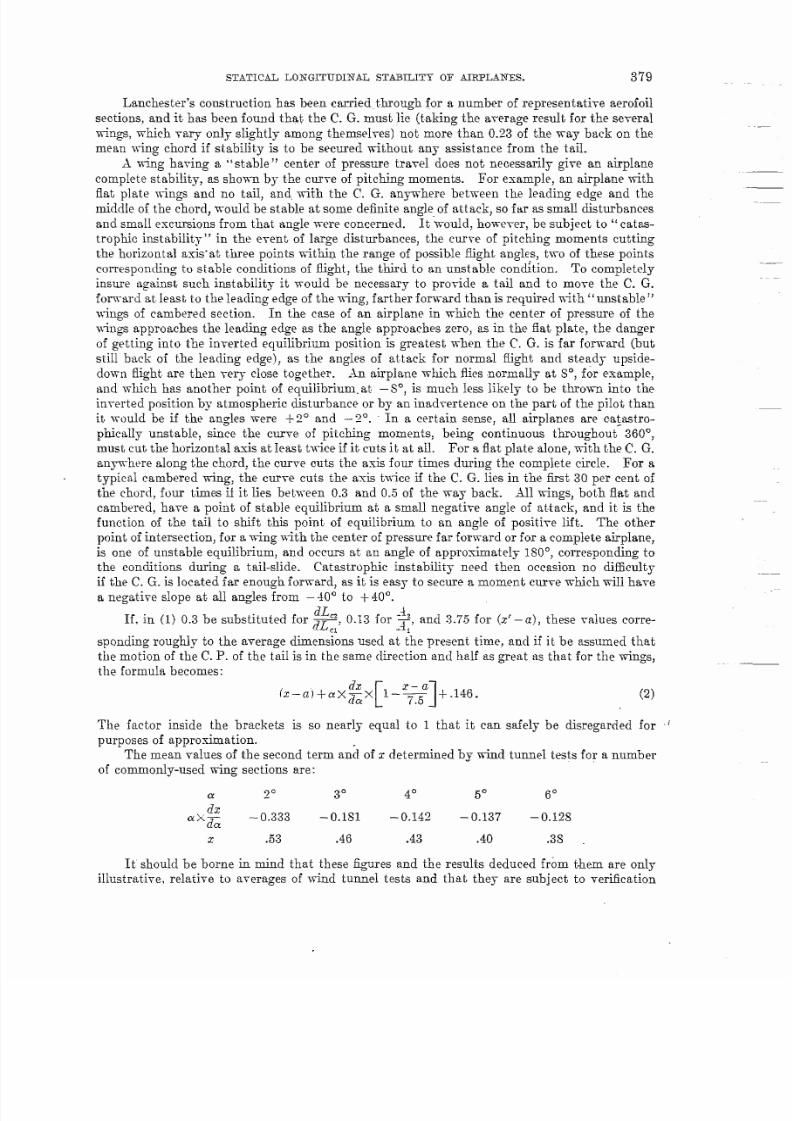
If, in (1) 0.3 be substituted for ~, 0.13 for ~}-, and 3.75 for (z’ – a), these values corre-Ft 1
spending rou@ly to the average dimens;om usecl at ~he present time, and if it be assumed that
the motion of the C. P. of the tail is in the same direction and half as ~meat as that for the wings,
the formuIa becomes:
“-a)+x~x[ ’ - =l +146 (2)
The factor inside the brackets is so nearly equal to 1 that it can safely be disregarded for ‘
purposes of approximation.
The mean values of the second term zn;l of r determined by wind tunnel tests for a number
of commonly-used wing sections are:
ago
3° 4° 5“fjo
(ix
akzz –0.333 –0.181 –0.142 –0.137 –().l~g
2 .53 .46 .43 .40 .3s
It should be borne in mind that these figures and the results deduced from them are only
iIIustrati-re, relati~e to a-rerages of wind tunnel tests and that they are subject to verification

7/27/2019 NCA TR 96 Statical Longitudinal Stability of Airplanes
http://slidepdf.com/reader/full/nca-tr-96-statical-longitudinal-stability-of-airplanes 8/28
380 ANNUALREPORT NATIONALADVISORYCOMIIITTEE FOR .4ER0.NAU’TICW
by free flight tests. Substituting these mean vaIues iu (2), the value which a must not exceed
in order that the moment curve may have a negative slope can atmnce be found. This value is
smallest for the smallest angle, where it is 0.35. In other words, the center of gravity of ihe
airplane must lie not more than 35 per cent of the way back on the mean wing chord if stabiliLy
is to be secured. If the tail area were decreased 50 per cent, the angle of set~ing being cllmged
St the same time but the section and plan form remaining fixed, the C. G. would have LObe
moved forward until a became less than 0.2S. If, Ori the other hancl, the tail etlicicncy, w
dL ,2— be increased 50 per cent without change of area (a feat which shoul(l not be
‘easured by dLC1
very difficult to accomplish in some present-day airplanes), the C. G. could be moved bwk to a
point about. 40 per cent of tile chord from the leading edge without causing the airplane to
become unstable. This backward movemen~ of the C. G. decreases the loud on the tail surfaces
and improves the’ general efficiency of flight.
SLIP-STREAM EFFECTS.
The analysis so far has proceeded on the assumption that all parts have the same speed
reiative to the air through which they pass. This assumption is correct in the case of gIiding
flight, but it is ver~T far from the truth with the throttle open, the mean fiir-speed at the tail
being much higher than that over the wings, since nearly the whole taiI Iies in the slip-stream {)nmost airplanes. If the sIip-stream velocity varied in the same manner and proportion as the
speed of the airplane relative to the undisturbed air the higher veIocity WOUMoperate only to
make the tail more effective and so to make the airpIane more stable. UnforLunfitely, however,
this condition does not prevail. Ifi has been shown by them-y and by experiment S 4 t,htit the
ratio of slip-stream velocity to air-speed increases as the air-speed decrcasesj and, in fact, that
the speed in the slip-stream is almost independent of the air-speed.
The pitching moment equation with allowance for the slip-stream, if it ‘be assurne(l tl~at
the whole of the tail, but no part of the wings, lie in the slip-stream, is:
where l’s is the slip-stream velocity. In this case the effect of a change in elevator setting is,
as before, to slide the moment curve vertically, but it slides the cur~7e parallel to itself only if
the velocity across the tail does not change. lt will be recalled that this same condition was
laid down in the case where slip-stream effec~ was ignored, and that the analytical work vim
accordingly carried through on the assumption that the velocity remained constaut, ~imihwly
in the present instance it will be necessary to assume that the slip-stream Yelocity passing ower
the tail remains constant while the speed of f-light varies. Differentiating M with rqwc L to
the angle of attack, treating V as a variable:
d M dLC,—— .da [ 1= X(z–a)X ~2+$~XLC,X 172+2 Vj;XLCl X(X-a) X.+
[ 1‘ – ; ’($’ – u) +d;; x L,z X <42XV,’
Strictlyalready
T’r
speaking, ~$~ instead of 1“, should be taken as an independent -ra.riablej but, as hasbeen pointed out, P. varies so little with airspeed in normal flight with wide-o~etl
thrott~e that i; can be considered in an approximate tre~tment as actuWy ;ernaining const&t..—
sPreliminaryeporton Fre*lWght Testing, by E. P. Warner and F. H. ~~orton:Report No. 70 ,Nat ional Advisory Committee for Aoro-
nautw, ‘Washington, 192).~Slip.. Stream.Cwreetlons in Performance Comportations, by E. P. Warner: Report h’o. 71, National Advisory Committ eefor Acronau tics,
WeArington, 1920.
Numerous reports ofthe British ,4dvisory Committee for Aeronautics also deal with this subject.

7/27/2019 NCA TR 96 Statical Longitudinal Stability of Airplanes
http://slidepdf.com/reader/full/nca-tr-96-statical-longitudinal-stability-of-airplanes 9/28
STATICAL LOKGITUDIA:AL ST-ABILITY OF AIRPLANES. 381
In order that the airplane may be in equilibrium, the condition
must hold true. If, as before, the lift
that
the equation of equi~ibrium becomes:
be assumed to be straight lines, so
Substituting the expression on the right-hand side of this equation for that on the left. in the
expression for the slope of the moment curw, so as to eliminate a’,
[
r
j;= (X–a)xl’’+gxc’x TV2r~$&?. x.(x-a)——1<AIxa&
~ dLm
[ 1~ x(z’–(z)xii, x~ ’.’ –dLfl ,, >.dX’
~x :<.41 x v’:= A cz,.. d;
Taking -4,, ~~ arid 1“$ OULas factors, the condition of statical stabiIit.y becomes:
[’;-a ’;’(EYl+ [&xa x(~ iYl+ P &yY’”x@-”J l+
dLG A,
[ 1 [:= ’K7X”4%”x-p(z’-a ) –c1 1
If tthe airplane is in le-wl or appro.ximately leveI flight (inclination not in excess of 2 0“],
as is usualIy the case when the throttIe is open,
Ti’=Lclx Aix r~=a~(lL-&x.41x P
neglecting the lift on the t aiI, where W is the total weight of the machine. Then
Substituting this ~alue f or’~ in the stability equation, the third term exactly cancels the tit,and:
must be positive for stability. lt. tilI be rioted that the term depending directly on the relation
between the position of the C’. G. and that of the C!.P. of the wings does not appear in this
equation, and that ~. ~. position has only a very slight effect on stability. In fact, the stability
.

7/27/2019 NCA TR 96 Statical Longitudinal Stability of Airplanes
http://slidepdf.com/reader/full/nca-tr-96-statical-longitudinal-stability-of-airplanes 10/28
382 ANNUAL REPORT LTATLOA’ALDW30RY (lOMM1~TEK FOR AEROhTAUTIW.
can only be inc.re.ased, if the velocity of flow over the. tail be constant,, by increming the area
or efficiency of the taiI surfaces or the-length of the body.
It is evident that it is much more difficult to sewe stability when the velocity across the
tail is constant than when it varies in the same man~er .as that across the wings. The ~ctual
condition always lies somewhere between these two”e~tremes, and the stability is improrct I as
the tail is brought OUL of the slip-stream in whole or in part, thus approaching more nearly
the second limiting condition.
lt can be seen from physical reasoning that, if the slip-stream wlocity is kept constant.
while the air-speed varies in such a manner as to keep the lift. constant, the stabiIity must bc
nearly independent, of C. G. position, as the form of a curve of moments clue to a series of parallel
forces is independent of the position of the moment tixis if the sum of the upwarcl forces be
equal to the weight of the machine at every angle of attack , and R shift of the C’, G. tJwc-
fore changes the wing moment by the same amouni_f6r dl tingles.
F/g./.
It has been shown that it is always advantageous Lo
increase as much as possible the efficiency of the tail surfares
as measured by the sIope of the curve of lift mefficiwts. If a
section flat on one side and cambered on the othw be tvstcd
at both positive and negitive angles (measuring angIes from
the zero lift position and defining their signfi on the wst~nlp-tion that the cambered surface is uppermost), it is !ound that
the. curve of lift coefficient agtiil~st tingle of tittack hos the
general form shown in figure 1, and that the slope o! IJ~c ‘
curve at the point corresponding to any given positive lift
coefikient (except a very smaIl one) is materially greater than
that at the point where there is a neg;tive L, of the same
absolute magnitude. The tail-plane should therefore lN so
set, for best efficiency, as normally to work at a positive nngle.
Since the C. P. of the wings is behind the C. G. at all times on
some airplanes, and at all escept ~ery low speeds on all, t.hc
load on the tail-plane is normally downward. In or!ler thtit
there may bc a downward force while the tail is set. at a
positive angle of att~ck, using. the term positive ang]c todenote the condition in which the flat surface of the itiil
experiences a larger normal pressure (algebraic ~alue) than the camberyd surface, & tail musL
be inverted, with the flat surface on top. It appears from the analysis that this disposition,
which has been employed in the Pfalz and numerous other m~chines} possesses distiw t
advantages. The increase in stability by inversion of the tail should be greatest at high
speeds, w it is at high speeds that the normally placed tail-pIane meets tbc air at a large
negative angIe where the slope of the lift curve is small, ancl there is consequently more room
for improvement under those conditions than und~r any others. fit intermediate speeds,
where the load on the tail is small and where there B little difference in the form and +lpe (If
the lift curve for equal positive and negative coefficients, it shndd make little difference whcLher
the upper or lower surface is the cambered one. The position of the C. G. and thti tail area can
therefore be modified to change the stability .of the airplane at all speeds, while the relation
between stability at high speeds and at low can be controlled t o some cxtmt by altering thesectional form,
EXPER IMENTS ON STAB ILITY WITH LOCKED CONTROLS .
The experiments made to verify the above theory and to determine the degree of stability
fall into two classes. In the first the airp~ane was flown under the controI of the pilot, the
elevator angles were determined for se~eral air-speeds and a constant-throttle setting, and the
angles thus measured were plotted against air-speed. In the second series of experiments the
airplane -was actually flown with the elevator locked in several different positions and the uatmre
7/27/2019 NCA TR 96 Statical Longitudinal Stability of Airplanes
http://slidepdf.com/reader/full/nca-tr-96-statical-longitudinal-stability-of-airplanes 11/28
STATICAL LI)NGITUDIIIAL STABILITY OF MRF’LANFX. 383
of its motion was obser~ed. lrL order that the expertients might noti be complicated by any
interaction of longitudinal and IateraI stabiIity the locking device w-as so arranged as to permit
the stick to be moved from side to side whiIe keeping it in the same fore-and-aft position. The ‘
pilot was thus able at all times to make use of the rudder and ailerons to keep the airplane on
an even keel laterally. The measurement of elevator angles and the curves based on those
measurements admittedly are not very accurate in form, as the constant fluctuations in
position due to minute air d.istubances are large in comparison with the changes of angIe as
the speed ehangys, the stabiIi@ being wry near to neutral in most instances. HoweYer, whale
the accurac~ is not. great enough to permit of the making of cIeIicate determinations of the
point at wkuch the instability appears or of refined analysis of the effect of changes in the
airplane, it is still sufiicierk to show any large variations in stability and to check the analysis
approximately.
The variables which were changed in these experiments were:
(aj Horizontal position, or .37-coor&inate, of the Cl. G.
llj) Stagger.
(cl A.ngIe of setting of the tail-plane.
(d,) SectionaI form of t.aiI-plane.
I’eI ~~atical position, or Z-coordinate, of the C. G.
.i tJN4H was used in all these experiments. .kssembIy drawings of this airplane were givenin Report No. 70. The DH.4 is the only other type of airplane on which any ffl-scale experi-
ments on stability with locked co~trols or on e~e-rater positions have been carr~ed on in berica.
(b) has the same effect as (a) in that it mows the C. G. relatire to the -w@, but changing the
st~oer also has a direct effectl as it mofi~es the tra~el of the center of pressure of the wings.
IL is necessary to reduce the stagger b.dow normal if the C. G. is to be brought very far forward
on the mean chord, as the attac~ent of enough weight at the nose to move the C. G. to a
distance of less than one-third of the chord from the leading edge of the mean chord would
bring the C. G. so close beMnd the de = to entd seriousdanger of nosing over. The tail-
plane angle was moditied by pIacing blocks under the leading or trailing edge, the h being cut
away at the bottom to provide clearance. The sectional forms tested were three in number.
The standard tail was tested bow in norm~ petition and imertedj and the third arrangement
was a tail of symmetrical section made by attac~m convex fairings on the flat lower surfaces
of the ribs of the standard td. OI II Ya S hgle a lt er a tion w a s made in the vertical position ofthe C. G., a -w-eight being attached to the ade during one test.
The data permitting chrect study of the efiect of C?. G. pos it ion wi thou t the introduction
of any other complicattig factors are unfortunately rather sparse. .% already noted, the C. G’
can not be mo~ed far for-ward of its norm~ position tithout danger of nos% over} and mo-re-
ment to the rear through more th~ 3 or 4 per cent of the chord kngth makes the airpIane tail-
hea~ and tiresome, if not dangerous, to fly. Tests with the C. G. position coeflicien~ (the
ratio of the clistance between the le~~ng edge of the mean chord and a line through the C. G.
perpendicular to the thrusi hle to the ~ord length) at 0.365 and 0.335, the stagger being 13
iuches in both cases, show an improvement of stability with the throttle closed as the C. G. is
mo-r-ed forward. With the throttle open, the difference between the two cases is negligible.
This is strict~y in accordance with theoretical deduction. & in. the cases detailed in
Report No. 70, the airplane is stabIe at Iarge angles of attack and unstabIe at alI speeds beyond a
certain point. Insfiabilitty with the throttle closed appeam afi a mean speed of 78 m. p. h. with a
C. G. coefficient of 0.365, at S2 m. p. h.mhen the coefficient is 0.335. This difference, -while
distinct, is much smaller than tight have been predicted. It is probabIe that one reason for
the smalI apparenh effect of the C . G . posit ion k t ha t t he t ail-pla ne in t his ser ies of t est s w a s
blocked up to a negative angle (2.9° tO the top longerorO, that the elevators had to be pulled
down to maintain eqdibfinm, and that they were pfied dow n farther -when the C. G. was hack
aud the machine was tail-heavy than when it was forward. The combination of tail-plane and
elevator then acts roughly as a cmbered stiace, and the c~ber ~ deepes~ and the eflecti~e-
ness of the surface in producing lift is highest when Lhe C. G. is farthest back. This increased
54SS9—-21-25
.==-

7/27/2019 NCA TR 96 Statical Longitudinal Stability of Airplanes
http://slidepdf.com/reader/full/nca-tr-96-statical-longitudinal-stability-of-airplanes 12/28
384 ANNUAL REPORT NATIONAL ADVISORY C~~MITTEE I?OR AERONAUTICS.
effectiveness of the tail unit partially counterbalances tl~~less stalde form of the curve of moments
due to the wings. KTO even with a C!. G. coefficient of 0.2g, this being the farthest forward
position that was tried, was there complete stability at high speeds. The prediction from the
model test that stability at all speeds” would be obtained with a C. G. coefficient of 0.35 is thus
shown to be incorrect for this machine, and it is evident either that the travc] of the (.!. 1’. of
the wings in free-flight is dii?erent from that found from a model test or thai tJLo efficiency of
the tail k. less than was estimated. The latter is ~-ery probable, as the aspc,ct ratio of iho tail
is Iow and the section thin.
Changes in stagger, like those in C. G. position, had very little direct effect. lL is mxessary
to use a positive stagger of at least 50 per cent of the chord if any improvement in stability is
to be secured b-y modification of ihe nature of the center of pressure travel, and the maximum
stagger used in any of these tests on the ,JNT4Hwas the normal amount, 27 per cent.
The effect of modification in the taiI-plane angle wm much larger than had bwm anticipated,
h a concrete instance, three tests mad~ with different tail-plane settings ma~ be compared.
Wibh the taiI plane set flat on the top longerons, the airplane became unstable at 57 rg. p, h,
with throttle open and at 62 m, p, h. when gliding. With the tail-pIane se~ at – 1.4° to the top
longerons the corresponding figures were 67 and 72 m. p. h ., and when the anglo of settiug ~vas
increased to —2.9° the critical speed was 75 m. p. h.~buth with open and with closed tktr ttle.
lt can not be claimed that these speeds are correct to any high order of accurficy, buf, theyare probably good to within a maximum error of 6 m. p. h. and a probabIe error of 3 m. p. h.
The apparent change of stabilit~ with change of tail-plane setting is large enough so that,
despite the considerable errors wluch maybe present, the general trend of the, variation, at least.,
is fairly certain. It wfil be seen that the range of speed in which the airplane is staldc constantly
increases as the rem of the tail-plane is raised, This point& to a. considerable indirect
ad>-antage i~ moving the C. G. forward, as the elevator angle for zero force on the stick (a con-
dition always to be sought for whe~ in equilibrium at normal speeds, even if stability must be
sacrificed to obtain it) probably is nearIy indepenc?eut of the tail-plane setting, and the angle
between tail-plane and elevator when properly balanced is therefore greatest whe~ the C. G. is
far forward and when the tail-pIane has to be set at a large negative angle to keep the nom up.
It has already been pointed out that se~ting the two portions of the surface at a large angle to
each other improves the tail efficiency. Study of the results of wind tunnel tests on wings with
hinged rear portions set at various angIes does not inclicate a change in sIope of the lift coefficientcurve sufficient to ac~ount for the magnitude of the effects observed in the present e.speriments,
and it is probable that the direct effect of tail-plane setting would be much loss if tho tall were
of reasonably thick and efkcient section than it was in the present case where the section of
the tail approximated to that of a fiat plate. The effect of taiI-plane setting on stability was
much less marked in the DH4 tlian in the JNT(see Report hTc. 70).
The effect of sectional form is to change the reIatiYe stability at different speeds, as was
predicted from the theoretical analysis. The building up of the tail-pIane to a symmetrical
form increases the stability at high speeds whiIe decreasing it at 10W, and the inversion of the
tail-plane has the same effect in a still more marked degree. The inversion of the ~ail-plane
raised the speed at which instability appeared by 5 m. p. h., and made the instability much less
marked when it”did appear, the elevator angle with tkwot ile closed, with 6 inches stagger, and
with the tail-plane at – 10, varying through a totaI range of less than ~0 at all speeds from 60
LU91 m. p. h.!l?he next experiments dealt with the effect of lomering the C. G., the object being to reduce
the difference between the balance with throttle open and with throttle closed by bringing the
~. G. below the thrust line and so causing the thrust to produce a diving moment counterbalanc-
ing the stalliug moment due to the action of the slipstream on the controls. The C. G. was
lowered about 1~ inches’ in the only experime~t of this series so far conducted, and no cflw~ was
apparent, presumably because ~he change R-as not large enough. CaIcuIations of a ~ecw.
smily very approximate nature indicate tlmt the C. G. would have to be lowered about a foot
to bring the curves for all throttle settings into coincidence.
7/27/2019 NCA TR 96 Statical Longitudinal Stability of Airplanes
http://slidepdf.com/reader/full/nca-tr-96-statical-longitudinal-stability-of-airplanes 13/28
STATICAL L03-GITUDIN”ALSTABILITY OF AIRPLANES’. 385 .
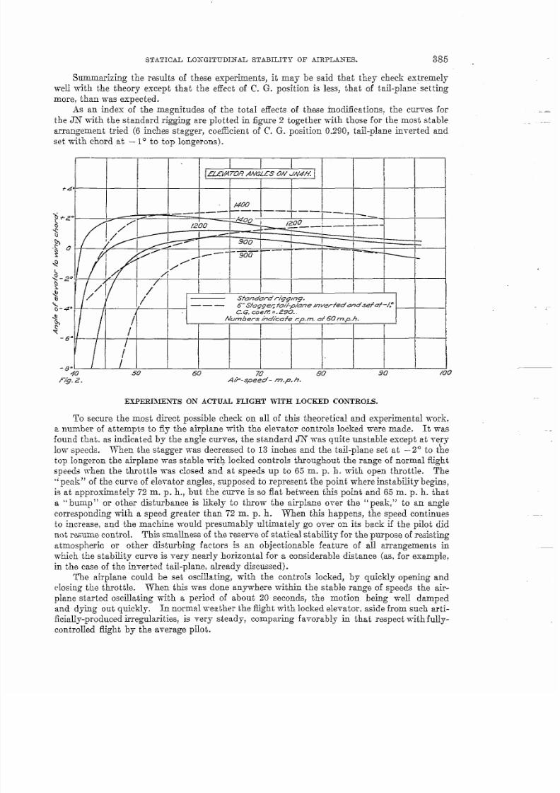
Summarizing the results of these experiments, it may be said that they cheek extremely
weIl with the theory except that the effect of C. G. position is less, that of tail-plane’ setting
more, than was expected.
.% an index ;f the magnitudes of the totaI effects of these modifications, the curws for
the JN with the standard rigging are pIotted in figure 2 together with those for the most stable
arrangement tried (6 inches stagger, coefficient of C. G. position 0.290} tad-plane inverted andset with chord at —10 to top longerms).
ELLV?TDR AWGL5S ON dV4H
*4
_ —.— —— ——— _
— ~ -
~
f ~
+
k~–~..
~ /
q
: / ___.S/andurdr/ggmg.
~-~. — . ~Sfogge~ fo#-p/one mverfedondsefaf -/,-
4/ C.G.coeff =.290..
p / ~Numbers kd%afe zp.m. af 60 m.p.h.
Y 1-6“
I
-8” ,
# 50 60 70 80 90 /00F/g..Z. A/?-speed- m.p.h.
E xP ERIMIWI ’S ON ACTUAL FLI GHT WITH LOCKED C 027H tOL S.
To secure the most direct possible check on alI of this theoretical and experimental work,
z Dumber of attempts to fly the airplane -&h the ele~ator controls locked were made. It vms
found that, as indicated by the angIe curms, the standard JN was quite unstable except at very
low- speeds. When the stagger was decreased to 13 inches and the taiI-pIane set at – 2° to t!he
top Iongeron the airpIane was stable with locked controls throughout the range of normal fiigght
speeds -when the throttIe was closed and at speeds up to 65 m. p. h. with open throMe. The
“peak” of the cur~e of ele~ator angIes, supposed to represent the point where instabdit y begins,
is at approximately 72 m. p. h., but the curve is so flat between this point and 6.5 m. p. h. that
a “bump” or other disturbance is likely to throw the airplane over the “ peak,” to an angle
correspond~o w%h a speed greater than 72 m. p. h. When this happens, the speed continues
to increase, and the machine w-ouId presumably ultimately go owr on its back if the pilot did
not resume cont,ro~. ‘Ms smakes-s of the reserYe of statical stability for the purpose of resisting
atmospheric or other disiurbiug factors is an objectionable feature of aIl arrangements in
which the sfiabiLit~ cuwe is very nearly horizontal for a considerable distance (as, for example,
in the case of the reverted tafi-plane, aheady discussed).
The aii-pIane could be sek osdlating, -with the controk locked, by quickIy opening and
cIosing the throttle. When this -was done anywhere within the stable r~~e of speeds the air-
plane started oscillating with a period of about 20 seconds, the motion be~m -weL1 damped
and dying out quickly. In normal weather the I&ht with locked elevator, aside from such arti-
ficially-produced irregularities, is very steady, comparing favorably in that respect with fully-
controIIed ~~ht by the average piIot.

7/27/2019 NCA TR 96 Statical Longitudinal Stability of Airplanes
http://slidepdf.com/reader/full/nca-tr-96-statical-longitudinal-stability-of-airplanes 14/28

7/27/2019 NCA TR 96 Statical Longitudinal Stability of Airplanes
http://slidepdf.com/reader/full/nca-tr-96-statical-longitudinal-stability-of-airplanes 15/28
7/27/2019 NCA TR 96 Statical Longitudinal Stability of Airplanes
http://slidepdf.com/reader/full/nca-tr-96-statical-longitudinal-stability-of-airplanes 16/28
7/27/2019 NCA TR 96 Statical Longitudinal Stability of Airplanes
http://slidepdf.com/reader/full/nca-tr-96-statical-longitudinal-stability-of-airplanes 17/28
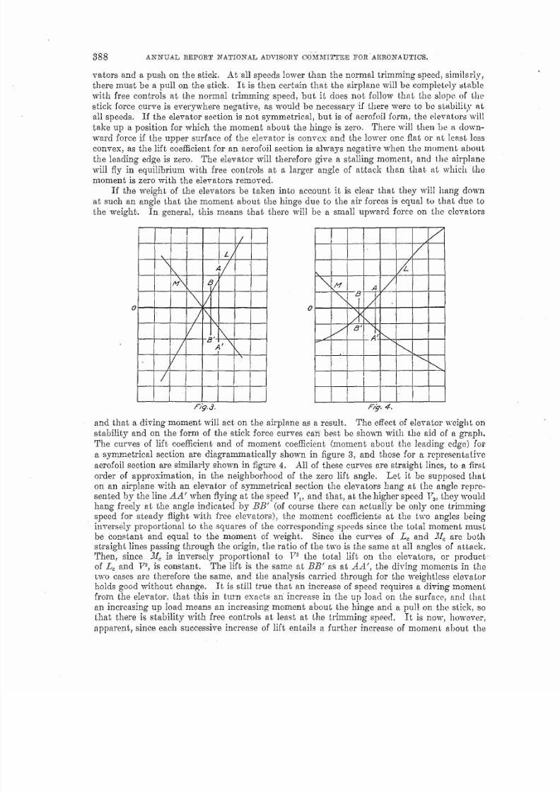
STATICAL LGNGITUDIN”AL ST&BHXCY OF AIRPLANES. 389
hinge, thmt the cum-e of stick forces has a positive sIope and a stabIe form throughout the
whoIe range of flight speeds.
Passing now to the ease of the aerofoil section, -where the curves of L. and MCDOlonger
intersect ah the origin, it is etident thafi it is no Ionger true that f.otaI lift and total moment
are in a fixed ratio to each other. In passing from .ti’ to BB’ in figure 4, choosing BB’ so that
Jf= P fi be constant, L= actu@y changes sign. For an aerofoiJ. section right side up, as thespeed increases and tic decreases the aIgebraic -raIue of ~ gro~s less and the diving moment due to
.ll.f
the free-hanging eIe~alor decreases and becomes at Yery high speeds a stalling moment.. This
is de&able from the standpoint of stability, as the free ele-rater works -with the tail-plane to
return the machine to its original attitude, and the force which must be exerted on the stick
to fly the airplane ak any speed other than its tr imming speed is thereby increased. If the
e~evators -were flat above and cambered below the condition wouId be reversed, and the lift
for constant h@e moment would change in a manner clisadwmt ageous for st abdit y.
In the case of an airp13ne where the ele-rater is hinged to the rear of a tail-plane it is only
possible to reason by analogy from the simpIer type of tail surface just discussed. The rela-
tionship between the moment and lift cciefEh@nts is now dependent in a rather indeterminate
manner on the angle of attack. In gerwraI, however, it is sufficient for stability” that the curve
of pitching moments should have a negati~e slope at W points when tested tithoufi the ele-vators and that a curve of coefilcients of moment about the elevator hinge pIott ed against
lift coef6cient shouId ha-re a negative sIope at all points for aIl angles of the tail-pIane. If the
tirst of these conditions is observed both with throttIe open and with throttle closed, the air-
plane wilI be stabIe with free controIs under both of these conditions of oper~t.ion. These
spetications are not absolutely rigorous, as the force on the tail-pIane and its effect on sta-
biIity are somew-hak affected by the presence of the eLeYator, especially if Lhe elevator is a
Lea-i-y o~e. The etliciency of the taiI is, as aLready noted, greatest when the ele~ator is set
at a com~iderable angle to the tail-p~ane. A heavy eIevator, which hangs down beIow the
line of the relati~e wind and -which require-s tha~ the taiI-pIane be set at a larger negative angle
to maintain eciuilibrium at any gi-ren speed than would be necessary with a lighter control
member, offers some advantage in this respect. Other things being equal, and neglecting the
direct eff eci of C. G. position on stabi~it y, a tail-heavy airplane would ha~e a more “stable”
curve of stick forces than would one properIy bahmced, as the elevator has to be pulled downto preser~e equilibrium on the tail-heavy machine and this increases the efficiency of the tail-
Plane. To secure a true meas~e of the effect of a change in C. G. position the tail-pla~e should
be adjusted, after the change, to such an angle that the airplane will trim with free controls
at the same speed as before, and it should be found, if tfi~ is doner that there nearIy always is an
improwmen~ of stability by moving the C’. G. forward: the exceptions being machines with
-iery small tail-planes.
.<nother reason, in addition to that just mentioned, for the increasingly stable form of the
stick force cur-re as the negative angle of taiI-pIane setting is increased; is that a gi-ien change
of setting means a change of lift coefficient for the tail-plane -which is approximately the same
for alI angles of’ attack. The total staIling moment due to the change is then proportional to
the square of the speed, and the additional up-ward force on the e~evator and decrease (alge-
braic ] of stick force necessary to produce a diving moment to balance this st aIIing moment is
accordingly greater at high speed than at low. The effect therefore is to mo-re the stick force
cum-e dovmward, as a -whole, but also to tilt it so tha~ negati~e slopes are increased, positi~e
slopes decreased. This phenomenon was dkcussed in Report N’o. 70, aIready refeired to on
se-reral occasiom~, in connection with the testing of a ~H-4 with several different settings of the
adjustable tail-plane. The condition connecting .LCand .MCfor the eIe-rater is observed on theB&~L+~. BK–~C@, .~~~ the ~’–~~, the o~y macb~e~ for ~~ch ~ge moment tests are ~~~i~able.
~Report OfBrit&h .%d}-iwryCommittee forAerOnwlic5,91%13,Rep. No. 74, p. 123.
J F1.diScale Experiment ORthe Moment about the Hinge of the Air Forces on an Elevstol; Bri tish Advisory Committee for -Aeromniics ,
R. & M.No. 2S.?,1916.I Buliet in of the Airplane Engineer ing Department, U. S. A.: Dec. , 1918.
7/27/2019 NCA TR 96 Statical Longitudinal Stability of Airplanes
http://slidepdf.com/reader/full/nca-tr-96-statical-longitudinal-stability-of-airplanes 18/28
390 ANNU.4L REPORT NATIONAL ADVISORY COMMITTEE FOR AERONAUTICS.
In f act~any elevator which did not have a lift-moment curve with a negative slopo d all points
would be o~erbalanced. The chief deduction to be drawn from this analysis is that models
should be tested for stabiIity in the wind tunnel with the elevators removed, and thd, if
stability with free controls is desired, the t.aiI-phme should be large enough so that the cur-ve
of pitching moments from such a test will have a negative sIope at alI points, both with and
without the slipstream eflect. This points directly to the advantage to be gained by the use
of a large tail-plane and small elevators. If possible, the tail-pl~ne and elevator should be
of such sectional form that there is a downward force on the ele~ator when the moment about
the hinge is zero.
1-Iezvy elevators me to be avoided for several reasom, cpief among -which is the eflcc~
of accelerations on the stick force required. To give a concrete instance, tho pull on the shick
required to baIance the weight of the elevators in a JN is 8+ pounds. In pulling out of a hop
with an acceleration of 3g, the stick force would be 25 pounds, even if there wme no air lord
at all on the elevator. In the ~7E-7 the pull under the same conditions would be only tihout
s pounds. A heavy elevator increases both the natmal period of oscillation of the airplane
with free controls and the damping of the motion, as the accelerations of the elevator turn it
down during the lower part of an oscillation, up during the upper part, always moving so as
to oppose the existing pitching motion of the airplane.
Before passing on to the discussion of experiments on stick forces something should be
said with regard to balanced controls. Overbalance may be defined as the condition in which
the curve of coefficient of hinge moment against lift coefficient for the elevator has a positive
slope at some points for some tail-pIane settings, and it is quite possible that some types of
elevator may be ove~balanced when hinged at the leading edge, although such a state of affairs
would be rare. If an elevator is much overbalanced the airplane is usually unpleasant, although ,
not necessarily dangerous, to fry. Curiously enough, the best stability with free controls if the
elevator hinges are too far back is obtained if the airplane is extrenleIy deficient in stability
with locked controls, If the machine is statically unstalde when tested without ~he elevators
there must be an up-ward force on those members at speeds beIow, a downward force at those
above, the equilibrium speed. The elevator being overbalanced at alI speeds, this gives a
push on the stick at high speeds and a pull at Iow. Actual flight with free controls would
hardly be possible, however, as the stick has no equilibrium position when the controls are.
overbalanced)- but moves quickly to one or the other of its extreme limits of travel as soon asreleased. FIight with free controls would be possibIe only if the elevators were fitted with
stops confining their oscillations between very narrow. limits.
Intentional and extreme overbalancing forms the basis of the” automatic rudders” inventcxl
by Col. Ckocco. The “ automatic rudder” consists of a tail plane hinged at the rem and with
the leading edge frea to move vertically but restrained by springs. If the aircraft noses down
the top load on the tail plane is increased and the leading edge moves downward, stiIl further
increasing the downward force on the tail plane and the righting moment derived therefrom.
The efficiency of the tail plane as a stabilizing factor can be trebled or quadrupled ii] this way.
This device has been successfully empIoyed on some ItaIian airships, and it theoretically is
cqualIy applicable to airplanes, but it would probabIy be rendered unsatisfactory in service
by excessive vibration of the tail plane. and because of the relatively short natural periods of
oscillation of an airpIane. overbalanced surfaces of any sort should in general bc avoided at.
all costs.EXPERIMENTS ON STAB I LITY WITH FREE CONTROL S.
The methods of conducting these experiments were explained in report No. 70. The
resuIts obtained with free controls are relatively more accurate than those. with locked controls,
largely because no communication between pilot and observer is required and because the
personal equation of only one individual enters into-the result. AIso, more data have bwm
obtained with free controk. because stick-force measurements can be made on any machine
without making the slightest change or inst aIIing any special equipmcnt~and such measure-
ments were therefore made on several airpIanes on which there -was no opportunity to install
an angle indicator. In aIl the tests on the JN the machine was piloted by Mr. R, G. Miller.

7/27/2019 NCA TR 96 Statical Longitudinal Stability of Airplanes
http://slidepdf.com/reader/full/nca-tr-96-statical-longitudinal-stability-of-airplanes 19/28

7/27/2019 NCA TR 96 Statical Longitudinal Stability of Airplanes
http://slidepdf.com/reader/full/nca-tr-96-statical-longitudinal-stability-of-airplanes 20/28

7/27/2019 NCA TR 96 Statical Longitudinal Stability of Airplanes
http://slidepdf.com/reader/full/nca-tr-96-statical-longitudinal-stability-of-airplanes 21/28
STATICAL IX)~’GITUDI~T.KL STABILITY” OF AIW’L4N?.S. 393
pounds-inches, corresponding to a chzqe in stick force of 5.7 pounds. Since the mefin separa-
tion between the curves for open and closed throttIe at. 60 m. p. h. is S.1 pounds it would theo-
retically be necessary to lower the C. G. by 1.4 feet in order to bring the cur-i-es to coincidence.
This -would mmifestly be impossible withoutt a co~plete change in the te~e of the airplane.
.¬her possible method, suggested by Mr. F. H. ~orton, for reduc~~ sIip-stream effect
on the controIs is to tip the e~tie dcm-n at the front so that, the slip-stream makes a smaller
ar@e with the tail-plane than does the relati~~ wind when there is no slip-stream. This WaS
tr{ed out by placing tapered blocks between the en.ggne and its bearers so as to incLine the hrust
line at 2° to the top Iongerons. Some improvement resdted from this change, bu~ the gain
[ I t I
I I15ZFECT OF TA /L -SECT@V ON STAB/L /TYN orm ul fai ~ –/.=4Symme f rk c 7/ s ~c fl ff o, 0 ?0 —–—– 2
~ /overfed fui /-p/uns j +2?0 ———— [
I /200 T 1 I + .1-- ..-Y / I
-4)I r I I I t I I I
@ 50 60 70 80 Jo
F/q.7. A/ i -speed - m -p. / 7 .
was not marked enough to justify the recommendation of such an inclination of the engine as a
reguIar feature of desigg. .%n inclination large enough to be of much use in neutralizi~~ the
slip-stream effect on the controIs would be distinct~y detrimental to efficiency a~ maximum
speed. The best -way that has yet appeared to reduce slip-stream tiect on a s&Ie-en@ed
machine is to use a t;il of Iarge aspect ratio so that a com~iderable portion of it w-N lie outside
of the sfip-stream.
In closing the tre~tment of the experiments on the J1l’, as an indication of the nek improve-
ment of stability which has resulted from all this work, there are plotted in figure S th~ curms
for the standard JN and for the best arrangement finalIy arri-red at (6 inches stagger, tail-plane
in-rerted and at —2° to the top Iongerons)- lt till be obser~ed that there is a great impro~e-
meDt in stability, especially at high speeds? and that, the danger of the stick force in a di-re
increasing to a point where it would be impossible to pull the machine out has entirely dis-
appeared.

7/27/2019 NCA TR 96 Statical Longitudinal Stability of Airplanes
http://slidepdf.com/reader/full/nca-tr-96-statical-longitudinal-stability-of-airplanes 22/28
394 ANNUAL REPORT NATIONAL ADVISORY COMMITTEE FOR AERONAUTICS.
TE STS ON OTHER AI RP LANES .
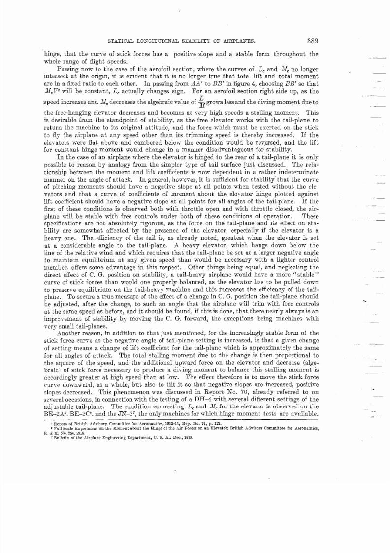
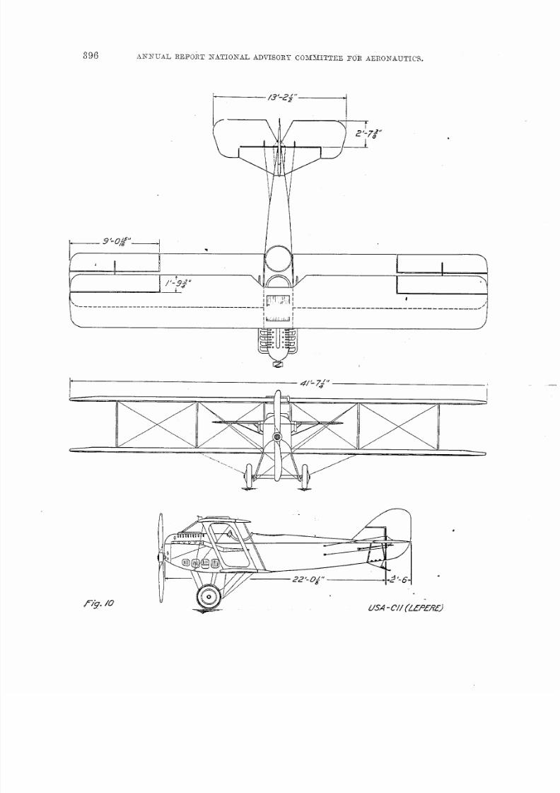
In addition to the DH4, the results for which were discussed in report NTO.70, siick-form
determinations have been made., through the courtesy of the &rphme Engineering Department
at McCook Field and particularity of Col. T. H. Bane lnd Lieut. Col. JT. E. Clark, on the W37
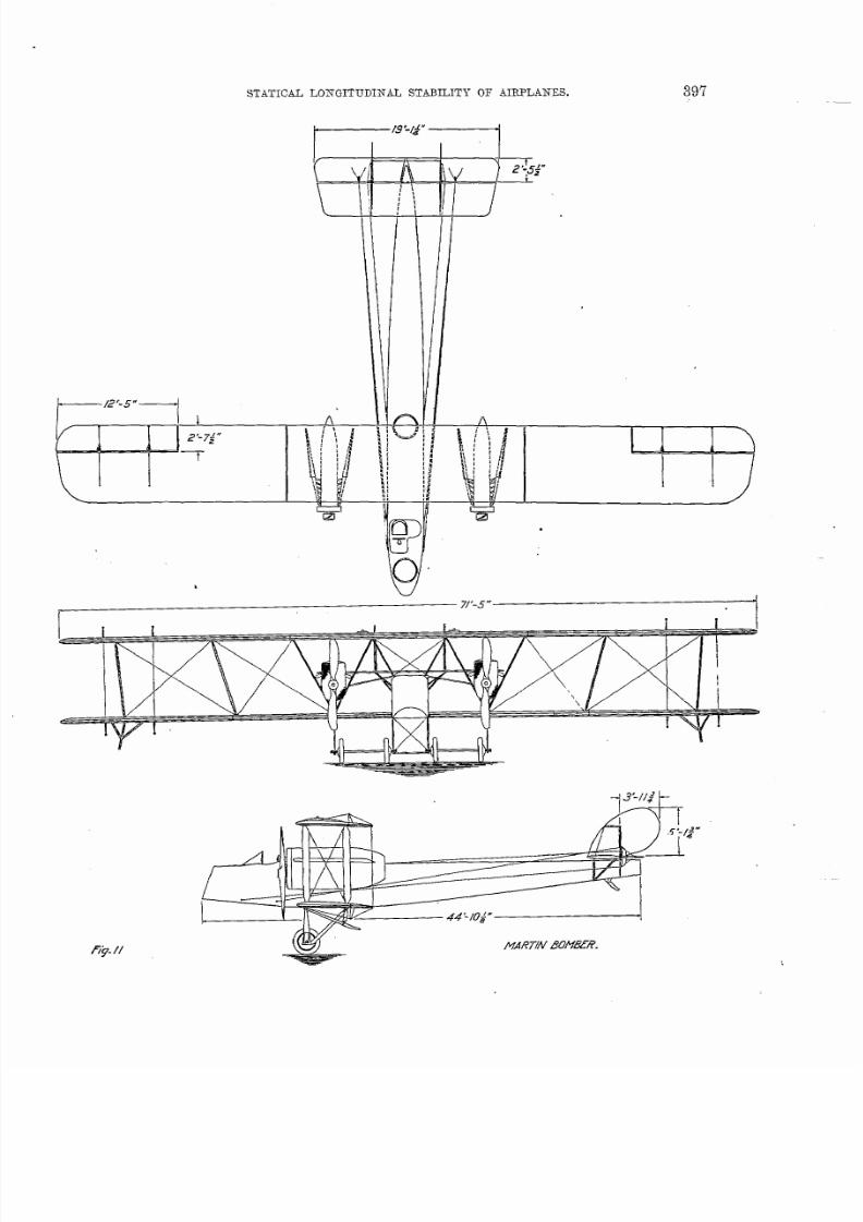
(~Tought), U. S. ~. Cll (Lepere Biplane), and Martin Transport. The assembly drawings of
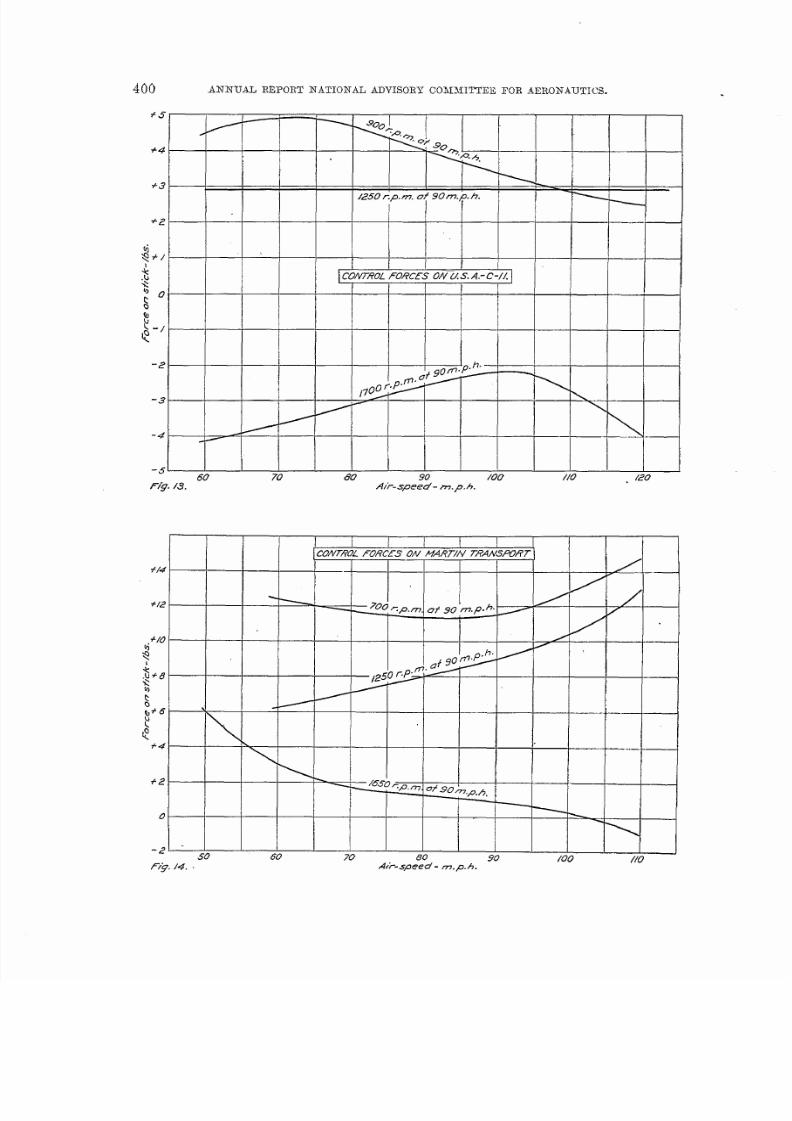
these three airplanes are reproduced in figures 9, 10, and 11. Ml three of these airplanes -wereflown during the tests by Lieut. H. R. Harris. The stick-force curves for the three machines
t~EFFECT OF CHANGES /+4R/GGl!G OffSTAB/L/TY Of JN414
/#orm u/r@gin?“ sf og gr r, f at -p km e .& v er fe u’
ondsefd —/; — — — —C. G. c oeff =. 290
Numbers fnd[c ofe <p.m . o/60 m .p.h.
\ \
\ / /
/
— _ 600 _—
< /—— /200 --—— ——.. __ __ .—
Al,.
/400—--- __
— ---
7 50 60 70 80
==+---
+
-—
-=4=
-1-1*
//
90 /00
./-
Fig. 8. A IF- speed - m .p.h.
are given in figures 12, 13, and 14. The curves for the Martin must be regarded with some
suspicion, as the friction in. the control system (of the column type) was so great as to malie it
impossible to be sure of the forces within 2 or 3 pouncls.
The stability of the TTE7 is -virtually ideal. This machine had the C. G. 30 per cent of the
way back on the mean chord and one-half inch below the thrust line. The tail-plane is convexon both surfoces, the upper camber being about twice the lower. Comparisons between different
machines show a remarkable clivergency in the location of the point of maximum stability, and
that location seems to be largely controlled by the section of the taiI. The DH4 and Lepere
have taik of virtual]y symmetrical section md are much more stable at high speeds than at low,
The JN has all its camber on the upper surface and is much more stabl~ at low speeds than at

7/27/2019 NCA TR 96 Statical Longitudinal Stability of Airplanes
http://slidepdf.com/reader/full/nca-tr-96-statical-longitudinal-stability-of-airplanes 23/28
STATICAL
‘—6’-7:”—’
LONGITUDINAL STABILITY OF MRE’LANES.
1,-. /* ‘.3:*
iI
Pi i“’”1
i-’-I
l--I
~+
I !..=—-~ . . . ..-.
i,P.jy-
!1
\
\/
‘. L-- .---—.—/i
———.-—-—————- .
/= //g. 9
7/27/2019 NCA TR 96 Statical Longitudinal Stability of Airplanes
http://slidepdf.com/reader/full/nca-tr-96-statical-longitudinal-stability-of-airplanes 24/28
7/27/2019 NCA TR 96 Statical Longitudinal Stability of Airplanes
http://slidepdf.com/reader/full/nca-tr-96-statical-longitudinal-stability-of-airplanes 25/28
LONGITUDINAL STABILITY OF AIRPLANES.
~—---- fs’-f.$” —-----
397

7/27/2019 NCA TR 96 Statical Longitudinal Stability of Airplanes
http://slidepdf.com/reader/full/nca-tr-96-statical-longitudinal-stability-of-airplanes 26/28

7/27/2019 NCA TR 96 Statical Longitudinal Stability of Airplanes
http://slidepdf.com/reader/full/nca-tr-96-statical-longitudinal-stability-of-airplanes 27/28
STATICAL LONGITUDINAL STABLGITY OF
controls were reIeased and left free for a lorg enough time
AMPLANES. 399
with the throttle closed. Fromzbout 1~000 to 1,300 r. p. m., however, the flight was more steady than with locked controIs and
more steady than it could be heId by the use of the controIs by an-y pilots except those of the
most exceptional skill. In fairly smooth air (not ideaI, but not unduly bumpy) the eIevator
moved continuously through a total angular range of about 0.5°. ldost of the triaIs were started
by reIeasing the stick while the airplane was diving steadiIy at about SO m. p. h. ~lth thethrottIe wide open the nose began to come up at once and continued to rise until the longitudinal
axis -was vertical, at which time the piIot resumed control. The machine stall had plenty of
speed and it is possible that ~if Ief t to itself> it would complete a loop with free controIs. With
the throttle partly opened the nose rose to a definite poin~ and then began to drop again, com-
t Ill 1 1CW7?CZF~CE.S ON 140&’ZWT YE-7 [
+-4
+3
q +2
$
$+(
$
QJb ~.
kk
-/
-2
50 60 70 80 90 /00 //’0 //5
F/g. /2. A/?.speed -m.p.h.
ing to an equilibrium position after two or three osdlations. The airphme was aIso flown in a
circuIar path with angIes of bank up to 15° and with the ele-rater control entirely free. The
steadiness of flight when circling, although sticient, was inferior to that with free controIs.
The subject of dynamical stability will be treated at Ien@h in a subsequent report, but a
few observations wiIl be noted here. The dynamical stability of the JN proved to be excellent,
the oscillations being head-y damped except in a few instances. The periods measured ranged
from 25 to 2S seconds, and the oscil~ations were by no means simple harmonic in form, the
nose rising much more slowly than it dropped, and seeming to creep gradually up to the most
stalled position, hang there for two or three seconds, and then drop abruptly.
The JT13-7 was also flown with free controls and was also found to be very steady, although
not quite so good as the .J2J in this respect. The periocl of oscfiation was from 14 to 17 seconds.
being shorter than orI the JN &iefly because of the smfilIer moment of inertia.54~C-21-26
7/27/2019 NCA TR 96 Statical Longitudinal Stability of Airplanes
http://slidepdf.com/reader/full/nca-tr-96-statical-longitudinal-stability-of-airplanes 28/28
400 ANNUAL REPORT hTATIONAL ADVISORY CONMI~EE FOR .413Rok’AuTIcS.
+5
-I
/
+4 ‘+ ~~ — — — –
+3 /250cp.m. of 9om.p.h.
+2
$+/
4I
.b ICONTROL FORCfS’ Ofl L/ S. A.- C-/LQ50
$
QI
?-/
t!
-2
-3 /
-4
-5-60 70 80 90 /00 //0 . /20
/%J./3. Air-speed- m.p.h.
CONTROL FORCES ON /WARTW TRAA
+— 700 <p.m. f f f 90 ,m.p.~,
A.?-speed -m.p.h. -