nc2 ash disposal area run-on and run-off control system …
TRANSCRIPT

NC2 Ash Disposal Area
Run-on and Run-off Control
System Plan
Omaha Public Power District
Nebraska City Station
Nebraska City, Nebraska
October 17, 2016

Page i
OPPD NC2 Ash Disposal Area
Run-On and Run-Off Control System Plan
Table of Contents
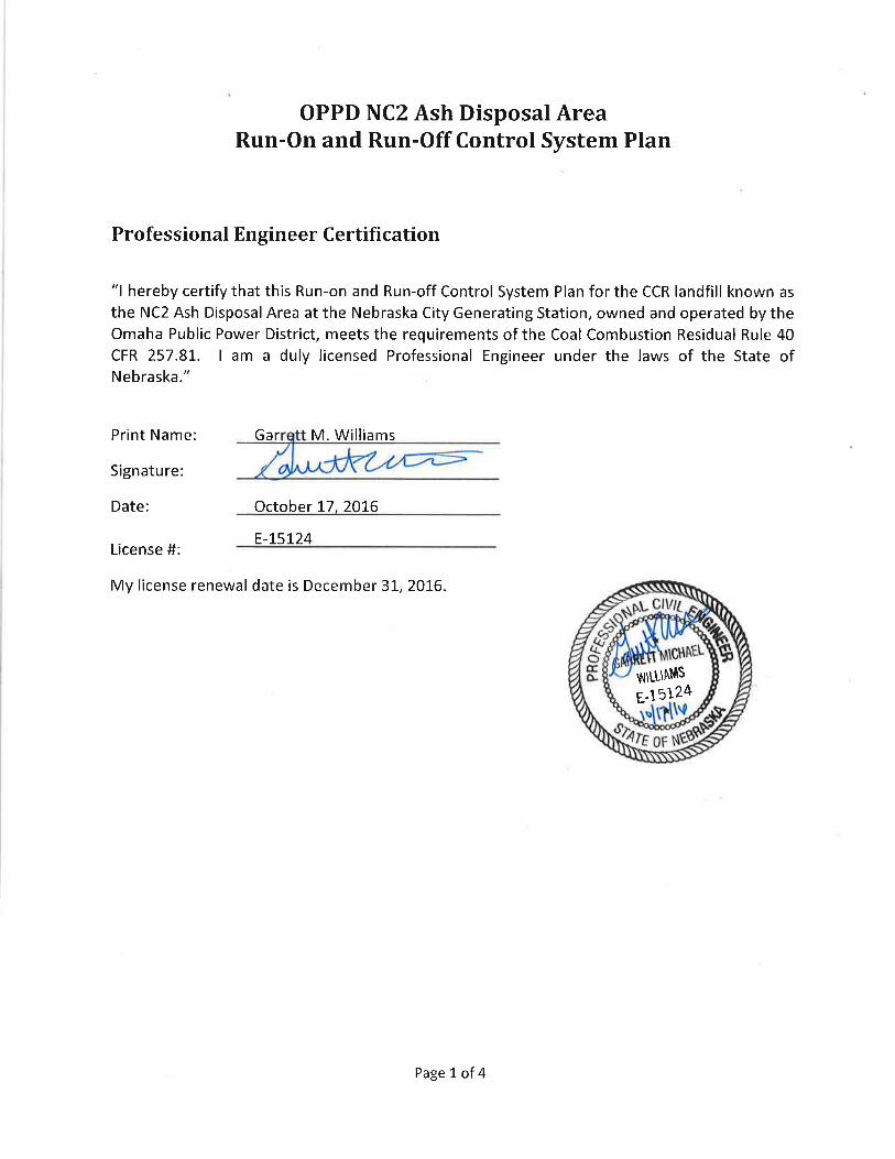
Professional Engineer Certification ............................................................................................................... 1
I. Introduction ....................................................................................................................................... 2
A. Purpose ............................................................................................................................................. 2
B. Facility Background ........................................................................................................................... 2
II. Run-On Control System .................................................................................................................... 2
III. Run-Off Control System ................................................................................................................ 3
Appendices Appendix A Stormwater Run-On Calculations
Appendix B Stormwater Run-Off Calculations and Figure
Appendix C Interior Collection Channel Calculations

Page 2 of 4
I. Introduction
A. Purpose
On April 17, 2015 the U.S. Environmental Protection Agency (EPA) published the final rule for
the regulation and management of coal combustion residuals (CCR) under the Resource
Conservation and Recovery Act (RCRA). Section 40 CFR 257.81 requires that an owner or
operator of a CCR landfill must prepare an initial run-on and run-off control system plan. The
plan must document how the control systems have been designed and constructed to meet the
applicable requirements of the CCR rule, supported by appropriate engineering calculations. In
accordance with the CCR rule 40 CFR 257.81, the intent of stormwater management is to
design, construct, operate, and maintain:
• A run-on control system to prevent flow onto the active portion of the CCR unit during
the peak discharge from a 24-hour, 25-year storm; and
• A run-off control system from the active portion of the CCR unit to collect and control at
least the water volume resulting from a 24-hour, 25-year storm. Run-off from the active
portion of the CCR unit must be handled in accordance with the surface water
requirements under 40 CFR 257.3-3.
B. Facility Background
OPPD has a two-unit (Unit 1 and Unit 2) fossil fuel-fired generating plant at the Nebraska City
Station (Station) located 5.5 miles southeast of Nebraska City, Nebraska, along the west shore
of the Missouri River. This Station has two (2) existing CCR landfills that are permitted under
the current Nebraska Department of Environmental Quality (NDEQ) Title 132 regulations for
fossil fuel combustion ash disposal area; the NC1 Ash Disposal Area and NC2 Ash Disposal Area.
This initial run-on and run-off control system plan is for the NC2 Ash Disposal Area (NDEQ
Permit No. NE0204421, Facility ID 58343). Under the CCR rule, the NC2 Ash Disposal Area is an
existing CCR landfill since it has and will receive CCR both before and after October 19, 2015 –
the effective date of the CCR rule.
The NC2 Ash Disposal Area is an existing CCR landfill with a composite liner and leachate
collection system, containing approximately 40.7 acres permitted disposal area. Cell 1
(approximately 14.4 acres) began accepting CCR in July 2009. Notification to the NDEQ and
construction on NC2 Ash Disposal Area Cells 2 and 3 began prior to October 19, 2015.
The NDEQ Title 132 permit for the NC2 Ash Disposal Area also includes descriptions,
calculations and figures of run-on and run-off control system features. This plan checks,
expands and confirms compliance with the CCR rule for run-on and run-off controls from the
active areas of the NC2 Ash Disposal Area.
II. Run-On Control System
The run-on control system for the NC2 Ash Disposal Area consists of perimeter berm roads,
ditches and grading sloped away from the CCR landfill to prevent stormwater run-on. As shown

Page 3 of 4
on the drawing in Appendix B, run-on to the NC2 Ash Disposal Area is prevented on the east,
south and west sides by constructed berms and roadways. Along the north side, potential run-
on would come from the railroad loop embankment. Perimeter ditches intercept, divert and
prevent potential storm water run-on to the NC2 Ash Disposal Area. Calculations confirming
the ditch and culvert capacities are included in Appendix A.
III. Run-Off Control System
The run-off control system for the NC2 Ash Disposal Area consists of interior collection
channels, culverts and leachate retention pond. When ash elevations in the Cell(s) reach the
perimeter road berms elevation, an interior perimeter drainage ditch within the disposal area,
appropriately sized, will be constructed at the edge of the CCR to collect and control the storm
water run-off from the active portions of the NC2 Ash Disposal Area. These temporary interior
channels will be constructed within the CCR disposal area footprint and will be graded to gravity
drain storm water run-off through constructed culverts to the leachate retention pond. The CCR
fill within the NC2 Ash Disposal Area has been and will be graded to facilitate surface water run-
off towards the interior channels.
The side-slopes of the Cell(s) are planned to be constructed no steeper than 3 horizontal to 1
vertical grade. Run-off from the NC2 Ash Disposal Area side-slopes will be conveyed via an
interior collection channel that will direct the water to the discharge point. Storm water will be
generated from two sub-basin areas as shown in the drawing in Appendix B. Sub-basin 1 will
generally consist of the stormwater runoff from the north side-slope that is captured by the
interior northern perimeter channel. Sub-basin 2 will generally consist of the stormwater
runoff from the west side-slope, also collected in an interior perimeter channel. Sub-basin 1
will be directed into the Sub-basin 2 perimeter channel. Storm water collected in the interior
perimeter channels eventually flows south into the leachate pond via three 24-inch HDPE
culverts. The three HDPE culverts are approximately 46-feet in length and have an inlet invert
elevation of 917.0 ft.
The remainder of the surface runoff consists of runoff from the Cells, and the eastern and
southern side-slopes. The runoff from these areas will flow generally in the southern direction
and will discharge into the leachate pond via three additional 24-inch HDPE culverts.
The contributing volume of runoff was modeled for a 25-year, 24-hour storm event. The
Rainfall depths were obtained from NOAA Atlas 14. The results of the hydrologic modeling, with
a sub-basin schematic, are found in Appendix B.
The interior collection channels were also sized to convey runoff for a 25-year, 24-hour storm
event. The north collection channel was sized to convey runoff from Sub-basin 1 and the west
collection channel was sized to contain runoff from both Sub-basin 1 and Sub-basin 2. Both
channels will have bottom width of 2-feet, be graded at minimum slope of 0.5% and have a
depth of 2.5-feet. The bottom width and depth of the channel will be consistent along the
length of both channels. The channel side-slope towards the interior of the cell will be 1.5
horizontal to 1 vertical up to the intersection with the CCR fill side-slope of 3 horizontal to 1

Page 4 of 4
vertical. The channel side-slope towards the outer perimeter of the cell is planned to be
constructed at 3 horizontal to 1 vertical.
The south collection channel was sized to convey runoff from Sub-basin 3a, Sub-basin 4a and
Sub-basin 4b to multiple culverts which drain to the leachate pond. The channel will have
bottom width of 2-feet, graded to a minimum 0.5% slope and depth of 3 feet. The area in front
of the culvert inlets will have a constructed pad to facilitate clean-out of settled CCR sediment.
Calculations checking the capacity of the interior channels are included in Appendix C.
The leachate retention pond located south of Cell 3 is being constructed as part of Cells 2 and 3
liner construction. This leachate retention pond is sized to adequately contain surface water
run-off, leachate, and storm water from the 25-year, 24-hour storm event. The leachate
retention pond has a capacity of approximately 735,000 cubic feet. In order to contain run-off
for the 25-year, 24-hour storm event and provide 1-foot of freeboard, the pond water surface
elevation must be maintained at 912.2 feet or lower. The pond has a bottom elevation of 911.0
feet with 1-foot of riprap and a top elevation of 919.0 feet. The pond has side-slopes at a 3
horizontal to 1 vertical grade.
Contact water generated from the 25-year, 24-hour storm (and lesser storms) will be collected,
controlled and conveyed to the leachate retention pond for management in accordance with
existing surface water requirements of the Station’s National Pollution Discharge Elimination
System (NPDES) permit.
Calculations, figures and management of stormwater run-off from the active portion of the NC2
Ash Disposal Area are contained in Appendices B and C of this plan.

Appendix A
Stormwater Run-On Calculations

Culvert Report
Hydraflow Express Extension for Autodesk® AutoCAD® Civil 3D® by Autodesk, Inc. Tuesday, Aug 23 2016
North Culvert
Invert Elev Dn (ft) = 923.11Pipe Length (ft) = 84.13Slope (%) = -2.51Invert Elev Up (ft) = 921.00Rise (in) = 30.0Shape = CircularSpan (in) = 30.0No. Barrels = 2n-Value = 0.012Culvert Type = Circular ConcreteCulvert Entrance = Square edge w/headwall (C)Coeff. K,M,c,Y,k = 0.0098, 2, 0.0398, 0.67, 0.5
EmbankmentTop Elevation (ft) = 930.00Top Width (ft) = 20.00Crest Width (ft) = 40.00
CalculationsQmin (cfs) = 0.00Qmax (cfs) = 15.00Tailwater Elev (ft) = Normal
HighlightedQtotal (cfs) = 13.00Qpipe (cfs) = 13.00Qovertop (cfs) = 0.00Veloc Dn (ft/s) = 1.32Veloc Up (ft/s) = 1.32HGL Dn (ft) = 925.61HGL Up (ft) = 925.63Hw Elev (ft) = 925.67Hw/D (ft) = 1.87Flow Regime = Outlet Control

Culvert Report
Hydraflow Express Extension for Autodesk® AutoCAD® Civil 3D® by Autodesk, Inc. Tuesday, Aug 23 2016
West Culvert
Invert Elev Dn (ft) = 914.00Pipe Length (ft) = 70.00Slope (%) = -1.43Invert Elev Up (ft) = 913.00Rise (in) = 30.0Shape = CircularSpan (in) = 30.0No. Barrels = 2n-Value = 0.012Culvert Type = Circular ConcreteCulvert Entrance = Square edge w/headwall (C)Coeff. K,M,c,Y,k = 0.0098, 2, 0.0398, 0.67, 0.5
EmbankmentTop Elevation (ft) = 920.00Top Width (ft) = 20.00Crest Width (ft) = 50.00
CalculationsQmin (cfs) = 0.00Qmax (cfs) = 15.00Tailwater Elev (ft) = Normal
HighlightedQtotal (cfs) = 10.00Qpipe (cfs) = 10.00Qovertop (cfs) = 0.00Veloc Dn (ft/s) = 1.02Veloc Up (ft/s) = 1.02HGL Dn (ft) = 916.50HGL Up (ft) = 916.51Hw Elev (ft) = 916.53Hw/D (ft) = 1.41Flow Regime = Outlet Control

Appendix B
Stormwater Run-Off Calculations
and Figure

MONITORING WELLW/ BOLLARD GUARDS
CONCRETE PADW/ BOLLARD GUARDSAND ELEC. METER
CONCRETE BOXW/ MANHOLE
CONCRETE PADW/ BOLLARD GUARDS
10" PVC PIPEW/ BOLLARD GUARD
24" CMP24" CMP
CELLS 2 AND 3 LINER
INTERIM FILL PLAN #1
PLAN AND CROSS-SECTIONS
#1A.3 Plan.dwg
AS SHOWN
1
1
A
B
C
2 3 4 5 6 7 8
D
ISSUE DESCRIPTION
PROJECT MANAGER
PROJECT NUMBER
0 1" 2"
FILENAME
SCALE
SHEET
DATE
OPPD Nebraska City Station Unit 2
G. WILLIAMS
10028555
CIVIL
0
G. WILLIAMS
Ash Landfill Expansion

1 - Subbasin 1
2 - Subbasin 2
3 - Subbasin 4a
4 - Subbasin 4b5 - Subbasin 3a
6 - Pond
7 - Interior Channel Runoff
8 - Combined Runoff
9 - Cells 2-3 Runoff
10 - <no description>
11 - North Culvert
12 - West Culvert
1
Watershed Model SchematicHydraflow Hydrographs Extension for AutoCAD® Civil 3D® 2014 by Autodesk, Inc. v10.3
Project: NC_Runoff-SMW Updated.gpw Tuesday, 08 / 23 / 2016

Hydrograph Report
Hydraflow Hydrographs Extension for AutoCAD® Civil 3D® 2014 by Autodesk, Inc. v10.3 Tuesday, 08 / 23 / 2016
Hyd. No. 1
Subbasin 1
Hydrograph type = SCS Runoff Peak discharge = 21.00 cfsStorm frequency = 25 yrs Time to peak = 11.93 hrsTime interval = 2 min Hyd. volume = 47,093 cuftDrainage area = 2.660 ac Curve number = 93Basin Slope = 0.0 % Hydraulic length = 0 ftTc method = User Time of conc. (Tc) = 5.00 minTotal precip. = 6.02 in Distribution = Type IIStorm duration = 24 hrs Shape factor = 484
2
0.0 2.0 4.0 6.0 8.0 10.0 12.0 14.0 16.0 18.0 20.0
Q (cfs)
0.00 0.00
4.00 4.00
8.00 8.00
12.00 12.00
16.00 16.00
20.00 20.00
24.00 24.00
Q (cfs)
Time (hrs)
Subbasin 1
Hyd. No. 1 -- 25 Year
Hyd No. 1

Hydrograph Report
Hydraflow Hydrographs Extension for AutoCAD® Civil 3D® 2014 by Autodesk, Inc. v10.3 Tuesday, 08 / 23 / 2016
Hyd. No. 2
Subbasin 2
Hydrograph type = SCS Runoff Peak discharge = 13.66 cfsStorm frequency = 25 yrs Time to peak = 11.93 hrsTime interval = 2 min Hyd. volume = 30,628 cuftDrainage area = 1.730 ac Curve number = 93Basin Slope = 0.0 % Hydraulic length = 0 ftTc method = User Time of conc. (Tc) = 5.00 minTotal precip. = 6.02 in Distribution = Type IIStorm duration = 24 hrs Shape factor = 484
3
0.0 2.0 4.0 6.0 8.0 10.0 12.0 14.0 16.0 18.0 20.0
Q (cfs)
0.00 0.00
2.00 2.00
4.00 4.00
6.00 6.00
8.00 8.00
10.00 10.00
12.00 12.00
14.00 14.00
Q (cfs)
Time (hrs)
Subbasin 2
Hyd. No. 2 -- 25 Year
Hyd No. 2

Hydrograph Report
Hydraflow Hydrographs Extension for AutoCAD® Civil 3D® 2014 by Autodesk, Inc. v10.3 Tuesday, 08 / 23 / 2016
Hyd. No. 3
Subbasin 4a
Hydrograph type = SCS Runoff Peak discharge = 90.80 cfsStorm frequency = 25 yrs Time to peak = 11.93 hrsTime interval = 2 min Hyd. volume = 203,598 cuftDrainage area = 11.500 ac Curve number = 93Basin Slope = 0.0 % Hydraulic length = 0 ftTc method = User Time of conc. (Tc) = 5.00 minTotal precip. = 6.02 in Distribution = Type IIStorm duration = 24 hrs Shape factor = 484
4
0.0 2.0 4.0 6.0 8.0 10.0 12.0 14.0 16.0 18.0 20.0
Q (cfs)
0.00 0.00
10.00 10.00
20.00 20.00
30.00 30.00
40.00 40.00
50.00 50.00
60.00 60.00
70.00 70.00
80.00 80.00
90.00 90.00
100.00 100.00
Q (cfs)
Time (hrs)
Subbasin 4a
Hyd. No. 3 -- 25 Year
Hyd No. 3
Hydrograph Report
Hydraflow Hydrographs Extension for AutoCAD® Civil 3D® 2014 by Autodesk, Inc. v10.3 Tuesday, 08 / 23 / 2016
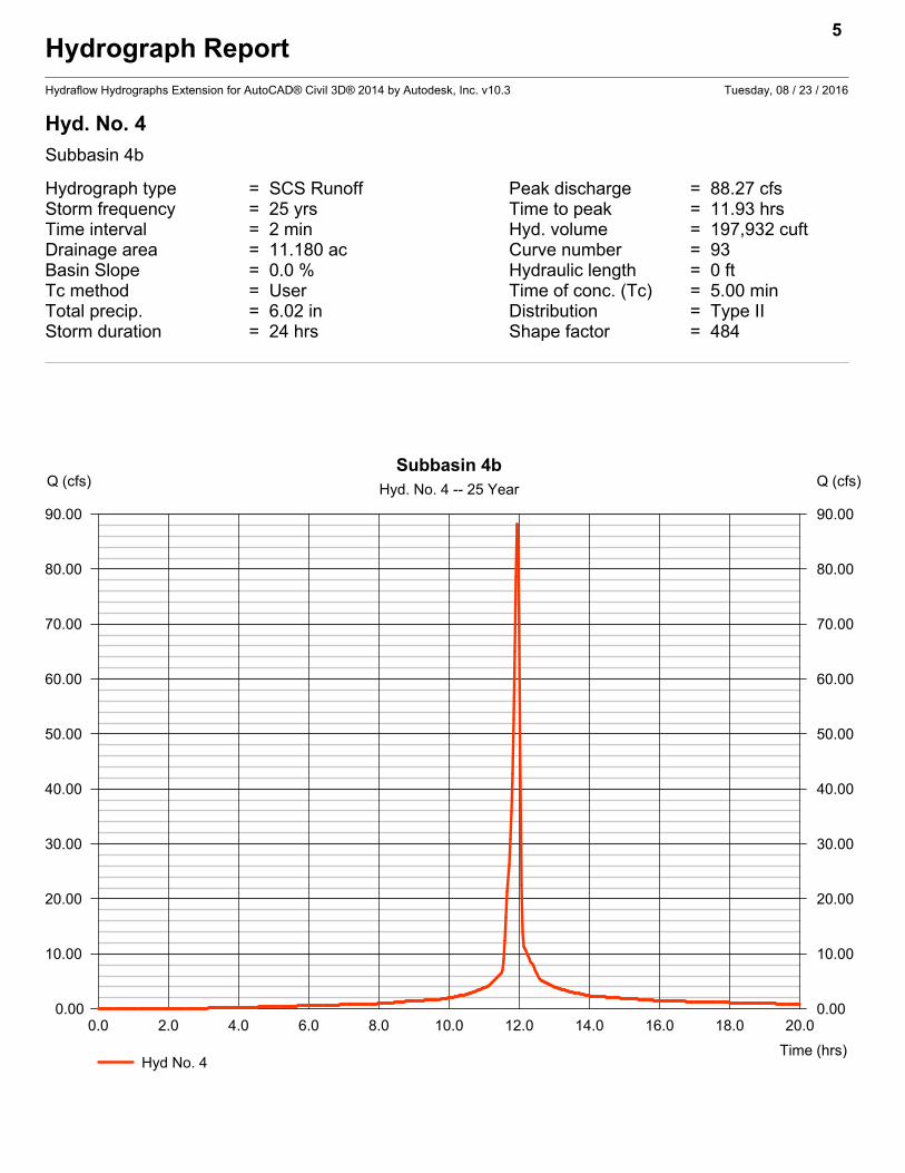
Hyd. No. 4
Subbasin 4b
Hydrograph type = SCS Runoff Peak discharge = 88.27 cfsStorm frequency = 25 yrs Time to peak = 11.93 hrsTime interval = 2 min Hyd. volume = 197,932 cuftDrainage area = 11.180 ac Curve number = 93Basin Slope = 0.0 % Hydraulic length = 0 ftTc method = User Time of conc. (Tc) = 5.00 minTotal precip. = 6.02 in Distribution = Type IIStorm duration = 24 hrs Shape factor = 484
5
0.0 2.0 4.0 6.0 8.0 10.0 12.0 14.0 16.0 18.0 20.0
Q (cfs)
0.00 0.00
10.00 10.00
20.00 20.00
30.00 30.00
40.00 40.00
50.00 50.00
60.00 60.00
70.00 70.00
80.00 80.00
90.00 90.00
Q (cfs)
Time (hrs)
Subbasin 4b
Hyd. No. 4 -- 25 Year
Hyd No. 4

Hydrograph Report
Hydraflow Hydrographs Extension for AutoCAD® Civil 3D® 2014 by Autodesk, Inc. v10.3 Tuesday, 08 / 23 / 2016
Hyd. No. 5
Subbasin 3a
Hydrograph type = SCS Runoff Peak discharge = 3.943 cfsStorm frequency = 25 yrs Time to peak = 11.93 hrsTime interval = 2 min Hyd. volume = 9,057 cuftDrainage area = 0.490 ac Curve number = 95Basin Slope = 0.0 % Hydraulic length = 0 ftTc method = User Time of conc. (Tc) = 5.00 minTotal precip. = 6.02 in Distribution = Type IIStorm duration = 24 hrs Shape factor = 484
6
0.0 2.0 4.0 6.0 8.0 10.0 12.0 14.0 16.0 18.0 20.0
Q (cfs)
0.00 0.00
1.00 1.00
2.00 2.00
3.00 3.00
4.00 4.00
Q (cfs)
Time (hrs)
Subbasin 3a
Hyd. No. 5 -- 25 Year
Hyd No. 5

Hydrograph Report
Hydraflow Hydrographs Extension for AutoCAD® Civil 3D® 2014 by Autodesk, Inc. v10.3 Tuesday, 08 / 23 / 2016
Hyd. No. 6
Pond
Hydrograph type = SCS Runoff Peak discharge = 22.95 cfsStorm frequency = 25 yrs Time to peak = 11.93 hrsTime interval = 2 min Hyd. volume = 57,158 cuftDrainage area = 2.790 ac Curve number = 100Basin Slope = 0.0 % Hydraulic length = 0 ftTc method = User Time of conc. (Tc) = 5.00 minTotal precip. = 6.02 in Distribution = Type IIStorm duration = 24 hrs Shape factor = 484
7
0.0 2.0 4.0 6.0 8.0 10.0 12.0 14.0 16.0 18.0 20.0
Q (cfs)
0.00 0.00
4.00 4.00
8.00 8.00
12.00 12.00
16.00 16.00
20.00 20.00
24.00 24.00
Q (cfs)
Time (hrs)
Pond
Hyd. No. 6 -- 25 Year
Hyd No. 6

Hydrograph Report
Hydraflow Hydrographs Extension for AutoCAD® Civil 3D® 2014 by Autodesk, Inc. v10.3 Tuesday, 08 / 23 / 2016
Hyd. No. 7
Interior Channel Runoff
Hydrograph type = Combine Peak discharge = 34.66 cfsStorm frequency = 25 yrs Time to peak = 11.93 hrsTime interval = 2 min Hyd. volume = 77,721 cuftInflow hyds. = 1, 2 Contrib. drain. area = 4.390 ac
8
0.0 2.0 4.0 6.0 8.0 10.0 12.0 14.0 16.0 18.0 20.0
Q (cfs)
0.00 0.00
5.00 5.00
10.00 10.00
15.00 15.00
20.00 20.00
25.00 25.00
30.00 30.00
35.00 35.00
Q (cfs)
Time (hrs)
Interior Channel Runoff
Hyd. No. 7 -- 25 Year
Hyd No. 7 Hyd No. 1 Hyd No. 2

Hydrograph Report
Hydraflow Hydrographs Extension for AutoCAD® Civil 3D® 2014 by Autodesk, Inc. v10.3 Tuesday, 08 / 23 / 2016
Hyd. No. 8
Combined Runoff
Hydrograph type = Combine Peak discharge = 94.74 cfsStorm frequency = 25 yrs Time to peak = 11.93 hrsTime interval = 2 min Hyd. volume = 212,655 cuftInflow hyds. = 3, 5 Contrib. drain. area = 11.990 ac
9
0.0 2.0 4.0 6.0 8.0 10.0 12.0 14.0 16.0 18.0 20.0
Q (cfs)
0.00 0.00
10.00 10.00
20.00 20.00
30.00 30.00
40.00 40.00
50.00 50.00
60.00 60.00
70.00 70.00
80.00 80.00
90.00 90.00
100.00 100.00
Q (cfs)
Time (hrs)
Combined Runoff
Hyd. No. 8 -- 25 Year
Hyd No. 8 Hyd No. 3 Hyd No. 5

Hydrograph Report
Hydraflow Hydrographs Extension for AutoCAD® Civil 3D® 2014 by Autodesk, Inc. v10.3 Tuesday, 08 / 23 / 2016
Hyd. No. 9
Cells 2-3 Runoff
Hydrograph type = Combine Peak discharge = 240.63 cfsStorm frequency = 25 yrs Time to peak = 11.93 hrsTime interval = 2 min Hyd. volume = 545,467 cuftInflow hyds. = 4, 6, 7, 8 Contrib. drain. area = 13.970 ac
10
0.0 2.0 4.0 6.0 8.0 10.0 12.0 14.0 16.0 18.0 20.0
Q (cfs)
0.00 0.00
40.00 40.00
80.00 80.00
120.00 120.00
160.00 160.00
200.00 200.00
240.00 240.00
280.00 280.00
Q (cfs)
Time (hrs)
Cells 2-3 Runoff
Hyd. No. 9 -- 25 Year
Hyd No. 9 Hyd No. 4 Hyd No. 6 Hyd No. 7
Hyd No. 8

Hydrograph Report
Hydraflow Hydrographs Extension for AutoCAD® Civil 3D® 2014 by Autodesk, Inc. v10.3 Tuesday, 08 / 23 / 2016
Hyd. No. 10
<no description>
Hydrograph type = Reservoir Peak discharge = 0.000 cfsStorm frequency = 25 yrs Time to peak = n/aTime interval = 2 min Hyd. volume = 0 cuftInflow hyd. No. = 9 - Cells 2-3 Runoff Max. Elevation = 917.95 ftReservoir name = Permit West Pond Max. Storage = 621,910 cuft
Storage Indication method used. Wet pond routing start elevation = 912.20 ft.
11
0.0 2.0 4.0 6.0 8.0 10.0 12.0 14.0 16.0 18.0 20.0
Q (cfs)
0.00 0.00
40.00 40.00
80.00 80.00
120.00 120.00
160.00 160.00
200.00 200.00
240.00 240.00
280.00 280.00
Q (cfs)
Time (hrs)
<no description>
Hyd. No. 10 -- 25 Year
Hyd No. 10 Hyd No. 9 Total storage used = 621,910 cuft


Hydrograph Report
Hydraflow Hydrographs Extension for AutoCAD® Civil 3D® 2014 by Autodesk, Inc. v10.3 Tuesday, 08 / 23 / 2016
Hyd. No. 11
North Culvert
Hydrograph type = SCS Runoff Peak discharge = 12.63 cfsStorm frequency = 25 yrs Time to peak = 11.93 hrsTime interval = 2 min Hyd. volume = 28,327 cuftDrainage area = 1.600 ac Curve number = 93Basin Slope = 0.0 % Hydraulic length = 0 ftTc method = User Time of conc. (Tc) = 5.00 minTotal precip. = 6.02 in Distribution = Type IIStorm duration = 24 hrs Shape factor = 484
13
0.0 2.0 4.0 6.0 8.0 10.0 12.0 14.0 16.0 18.0 20.0
Q (cfs)
0.00 0.00
2.00 2.00
4.00 4.00
6.00 6.00
8.00 8.00
10.00 10.00
12.00 12.00
14.00 14.00
Q (cfs)
Time (hrs)
North Culvert
Hyd. No. 11 -- 25 Year
Hyd No. 11

Hydrograph Report
Hydraflow Hydrographs Extension for AutoCAD® Civil 3D® 2014 by Autodesk, Inc. v10.3 Tuesday, 08 / 23 / 2016
Hyd. No. 12
West Culvert
Hydrograph type = SCS Runoff Peak discharge = 10.26 cfsStorm frequency = 25 yrs Time to peak = 11.93 hrsTime interval = 2 min Hyd. volume = 23,015 cuftDrainage area = 1.300 ac Curve number = 93Basin Slope = 0.0 % Hydraulic length = 0 ftTc method = User Time of conc. (Tc) = 5.00 minTotal precip. = 6.02 in Distribution = Type IIStorm duration = 24 hrs Shape factor = 484
14
0.0 2.0 4.0 6.0 8.0 10.0 12.0 14.0 16.0 18.0 20.0
Q (cfs)
0.00 0.00
2.00 2.00
4.00 4.00
6.00 6.00
8.00 8.00
10.00 10.00
12.00 12.00
Q (cfs)
Time (hrs)
West Culvert
Hyd. No. 12 -- 25 Year
Hyd No. 12

NOAA Atlas 14, Volume 8, Version 2 Location name: Nebraska City, Nebraska, US*
Latitude: 40.6188°, Longitude: -95.7842° Elevation: 931 ft* * source: Google Maps
POINT PRECIPITATION FREQUENCY ESTIMATES
Sanja Perica, Deborah Martin, Sandra Pavlovic, Ishani Roy, Michael St. Laurent, Carl Trypaluk, Dale Unruh, Michael Yekta, Geoffery Bonnin
NOAA, National Weather Service, Silver Spring, Maryland
PF_tabular | PF_graphical | Maps_&_aerials
PF tabular
PDS-based point precipitation frequency estimates with 90% confidence intervals (in inches)1
DurationAverage recurrence interval (years)
1 2 5 10 25 50 100 200 500 1000
5-min0.405
(0.324-0.517)
0.476(0.381-0.608)
0.595(0.475-0.761)
0.697(0.553-0.893)
0.841(0.647-1.10)
0.955(0.717-1.25)
1.07(0.779-1.43)
1.19(0.832-1.61)
1.36(0.911-1.85)
1.49(0.971-2.04)
10-min0.593
(0.475-0.757)0.697
(0.558-0.890)0.872
(0.696-1.12)1.02
(0.810-1.31)1.23
(0.947-1.61)1.40
(1.05-1.84)1.57
(1.14-2.09)1.75
(1.22-2.35)1.99
(1.33-2.71)2.18
(1.42-2.99)
15-min0.723
(0.579-0.923)
0.850(0.681-1.09)
1.06(0.848-1.36)
1.25(0.988-1.60)
1.50(1.16-1.96)
1.71(1.28-2.24)
1.91(1.39-2.54)
2.13(1.49-2.87)
2.43(1.63-3.31)
2.65(1.73-3.64)
30-min1.02
(0.820-1.31)1.21
(0.968-1.55)1.52
(1.21-1.94)1.78
(1.42-2.29)2.16
(1.66-2.82)2.45
(1.84-3.22)2.75
(2.00-3.66)3.06
(2.14-4.12)3.49
(2.34-4.75)3.81
(2.49-5.23)
60-min1.33
(1.06-1.69)
1.57(1.25-2.00)
1.98(1.58-2.53)
2.34(1.85-2.99)
2.86(2.21-3.75)
3.29(2.47-4.33)
3.73(2.72-4.98)
4.20(2.94-5.67)
4.86(3.26-6.64)
5.38(3.51-7.38)
2-hr1.63
(1.32-2.05)
1.92(1.55-2.42)
2.43(1.96-3.07)
2.89(2.31-3.65)
3.56(2.78-4.64)
4.12(3.14-5.38)
4.71(3.47-6.23)
5.34(3.77-7.16)
6.23(4.23-8.46)
6.94(4.58-9.45)
3-hr1.81
(1.47-2.26)
2.13(1.73-2.66)
2.70(2.19-3.38)
3.22(2.60-4.04)
4.01(3.16-5.20)
4.67(3.58-6.08)
5.38(3.99-7.09)
6.15(4.37-8.21)
7.24(4.95-9.81)
8.13(5.39-11.0)
6-hr2.12
(1.74-2.61)
2.48(2.04-3.07)
3.16(2.59-3.91)
3.78(3.08-4.70)
4.75(3.79-6.11)
5.57(4.32-7.19)
6.46(4.84-8.44)
7.43(5.34-9.85)
8.83(6.10-11.9)
9.97(6.67-13.4)
12-hr2.43
(2.02-2.96)2.85
(2.37-3.48)3.62
(3.00-4.43)4.34
(3.57-5.31)5.43
(4.38-6.91)6.36
(4.99-8.12)7.37
(5.58-9.53)8.47
(6.15-11.1)10.0
(7.01-13.4)11.3
(7.66-15.1)
24-hr2.78
(2.34-3.35)
3.24(2.72-3.90)
4.07(3.41-4.91)
4.84(4.03-5.86)
6.02(4.90-7.57)
7.03(5.56-8.86)
8.11(6.20-10.4)
9.29(6.81-12.1)
11.0(7.73-14.5)
12.4(8.43-16.3)
2-day3.21
(2.72-3.81)
3.69(3.13-4.38)
4.57(3.87-5.44)
5.39(4.53-6.43)
6.63(5.45-8.22)
7.69(6.15-9.58)
8.83(6.82-11.2)
10.1(7.46-13.0)
11.9(8.44-15.5)
13.3(9.18-17.5)
3-day3.48
(2.98-4.10)
4.03(3.44-4.75)
5.00(4.25-5.90)
5.88(4.97-6.96)
7.19(5.94-8.83)
8.30(6.67-10.2)
9.47(7.35-11.9)
10.7(7.99-13.7)
12.5(8.96-16.3)
14.0(9.69-18.2)
4-day3.72
(3.20-4.36)
4.31(3.70-5.06)
5.35(4.57-6.28)
6.27(5.33-7.38)
7.63(6.32-9.30)
8.76(7.07-10.7)
9.96(7.75-12.4)
11.2(8.39-14.3)
13.0(9.35-16.9)
14.5(10.1-18.8)
7-day4.40
(3.81-5.09)5.02
(4.35-5.83)6.12
(5.28-7.11)7.10
(6.09-8.27)8.54
(7.12-10.3)9.72
(7.90-11.8)11.0
(8.61-13.5)12.3
(9.26-15.5)14.2
(10.2-18.2)15.7
(11.0-20.2)
10-day5.01
(4.36-5.76)
5.69(4.95-6.55)
6.87(5.96-7.92)
7.91(6.82-9.15)
9.45(7.92-11.3)
10.7(8.75-12.9)
12.0(9.50-14.8)
13.5(10.2-16.8)
15.4(11.2-19.7)
17.0(12.0-21.9)
20-day6.74
(5.94-7.65)7.69
(6.77-8.72)9.28
(8.14-10.6)10.7
(9.29-12.2)12.6
(10.7-14.8)14.2
(11.7-16.8)15.8
(12.6-19.1)17.5
(13.3-21.6)19.8
(14.5-25.0)21.6
(15.4-27.6)
30-day8.19
(7.26-9.21)
9.36(8.29-10.5)
11.3(9.98-12.7)
12.9(11.4-14.6)
15.2(12.9-17.7)
17.0(14.1-20.0)
18.8(15.0-22.5)
20.6(15.8-25.3)
23.1(17.0-29.0)
25.0(17.9-31.8)
45-day10.0
(8.95-11.2)
11.4(10.2-12.8)
13.8(12.2-15.4)
15.7(13.8-17.6)
18.2(15.5-20.9)
20.2(16.8-23.5)
22.1(17.8-26.3)
24.1(18.5-29.3)
26.7(19.7-33.1)
28.6(20.6-36.0)
60-day11.6
(10.4-12.9)
13.2(11.8-14.6)
15.8(14.1-17.5)
17.8(15.8-19.9)
20.6(17.6-23.4)
22.6(18.9-26.1)
24.6(19.9-29.0)
26.6(20.5-32.1)
29.1(21.6-35.9)
30.9(22.4-38.9)
1 Precipitation frequency (PF) estimates in this table are based on frequency analysis of partial duration series (PDS).
Numbers in parenthesis are PF estimates at lower and upper bounds of the 90% confidence interval. The probability that precipitation frequency estimates (for a given duration and average recurrence interval) will be greater than the upper bound (or less than the lower bound) is 5%. Estimates at upper bounds are not checked against probable maximum precipitation (PMP) estimates and may be higher than currently valid PMP values.
Please refer to NOAA Atlas 14 document for more information.
Back to Top
PF graphical
Page 1 of 4Precipitation Frequency Data Server
8/15/2016http://hdsc.nws.noaa.gov/hdsc/pfds/pfds_printpage.html?lat=40.6188&lon=-95.7842&data...

Back to Top
Maps & aerials
Small scale terrain
Map data ©2016 GoogleReport a map error50 km
Page 2 of 4Precipitation Frequency Data Server
8/15/2016http://hdsc.nws.noaa.gov/hdsc/pfds/pfds_printpage.html?lat=40.6188&lon=-95.7842&data...

Large scale terrain
Large scale map
Large scale aerial
Back to Top
US Department of CommerceNational Oceanic and Atmospheric Administration
National Weather ServiceNational Water Center
1325 East West HighwaySilver Spring, MD 20910
Map data ©2016 GoogleReport a map error2 km
Map data ©2016 GoogleReport a map error2 km
Imagery ©2016 TerraMetricsReport a map error2 km
Page 3 of 4Precipitation Frequency Data Server
8/15/2016http://hdsc.nws.noaa.gov/hdsc/pfds/pfds_printpage.html?lat=40.6188&lon=-95.7842&data...

Questions?: [email protected]
Disclaimer
Page 4 of 4Precipitation Frequency Data Server
8/15/2016http://hdsc.nws.noaa.gov/hdsc/pfds/pfds_printpage.html?lat=40.6188&lon=-95.7842&data...

Appendix C
Interior Collection Channel
Calculations

Channel Report
Hydraflow Express Extension for Autodesk® AutoCAD® Civil 3D® by Autodesk, Inc. Tuesday, Aug 23 2016
North Perimeter Ditch
TrapezoidalBottom Width (ft) = 2.00Side Slopes (z:1) = 3.00, 1.50Total Depth (ft) = 2.50Invert Elev (ft) = 10.00Slope (%) = 0.50N-Value = 0.016
CalculationsCompute by: Known QKnown Q (cfs) = 21.00
HighlightedDepth (ft) = 1.03Q (cfs) = 21.00Area (sqft) = 4.45Velocity (ft/s) = 4.72Wetted Perim (ft) = 7.11Crit Depth, Yc (ft) = 1.04Top Width (ft) = 6.63EGL (ft) = 1.38
0 2 4 6 8 10 12 14 16 18
Elev (ft) Depth (ft)Section
9.50 -0.50
10.00 0.00
10.50 0.50
11.00 1.00
11.50 1.50
12.00 2.00
12.50 2.50
13.00 3.00
Reach (ft)

Channel Report
Hydraflow Express Extension for Autodesk® AutoCAD® Civil 3D® by Autodesk, Inc. Tuesday, Aug 23 2016
West Perimeter Ditch
TrapezoidalBottom Width (ft) = 2.00Side Slopes (z:1) = 3.00, 1.50Total Depth (ft) = 2.50Invert Elev (ft) = 10.00Slope (%) = 0.50N-Value = 0.016
CalculationsCompute by: Known QKnown Q (cfs) = 14.00
HighlightedDepth (ft) = 0.84Q (cfs) = 14.00Area (sqft) = 3.27Velocity (ft/s) = 4.28Wetted Perim (ft) = 6.17Crit Depth, Yc (ft) = 0.85Top Width (ft) = 5.78EGL (ft) = 1.13
0 2 4 6 8 10 12 14 16 18
Elev (ft) Depth (ft)Section
9.50 -0.50
10.00 0.00
10.50 0.50
11.00 1.00
11.50 1.50
12.00 2.00
12.50 2.50
13.00 3.00
Reach (ft)

Channel Report
Hydraflow Express Extension for Autodesk® AutoCAD® Civil 3D® by Autodesk, Inc. Monday, Oct 17 2016
South Interior Channel
TrapezoidalBottom Width (ft) = 2.00Side Slopes (z:1) = 3.00, 1.50Total Depth (ft) = 3.00Invert Elev (ft) = 10.00Slope (%) = 0.50N-Value = 0.016
CalculationsCompute by: Known QKnown Q (cfs) = 100.00
HighlightedDepth (ft) = 2.10Q (cfs) = 100.00Area (sqft) = 14.12Velocity (ft/s) = 7.08Wetted Perim (ft) = 12.43Crit Depth, Yc (ft) = 2.22Top Width (ft) = 11.45EGL (ft) = 2.88
0 2 4 6 8 10 12 14 16 18 20
Elev (ft) Depth (ft)Section
9.00 -1.00
10.00 0.00
11.00 1.00
12.00 2.00
13.00 3.00
14.00 4.00
Reach (ft)

Culvert Report
Hydraflow Express Extension for Autodesk® AutoCAD® Civil 3D® by Autodesk, Inc. Monday, Oct 17 2016
East Culvert From Cell to Leachate Pond
Invert Elev Dn (ft) = 916.00Pipe Length (ft) = 57.00Slope (%) = 1.75Invert Elev Up (ft) = 917.00Rise (in) = 24.0Shape = CircularSpan (in) = 24.0No. Barrels = 3n-Value = 0.012Culvert Type = Circular CulvertCulvert Entrance = Smooth tapered inlet throatCoeff. K,M,c,Y,k = 0.534, 0.555, 0.0196, 0.9, 0.2
EmbankmentTop Elevation (ft) = 922.80Top Width (ft) = 20.00Crest Width (ft) = 20.00
CalculationsQmin (cfs) = 90.00Qmax (cfs) = 90.00Tailwater Elev (ft) = (dc+D)/2
HighlightedQtotal (cfs) = 90.00Qpipe (cfs) = 90.00Qovertop (cfs) = 0.00Veloc Dn (ft/s) = 9.65Veloc Up (ft/s) = 9.85HGL Dn (ft) = 917.93HGL Up (ft) = 918.86Hw Elev (ft) = 920.57Hw/D (ft) = 1.78Flow Regime = Inlet Control

Culvert Report
Hydraflow Express Extension for Autodesk® AutoCAD® Civil 3D® by Autodesk, Inc. Monday, Oct 17 2016
West Culvert From Cell to Leachate Pond
Invert Elev Dn (ft) = 915.00Pipe Length (ft) = 46.00Slope (%) = 4.35Invert Elev Up (ft) = 917.00Rise (in) = 24.0Shape = CircularSpan (in) = 24.0No. Barrels = 3n-Value = 0.012Culvert Type = Circular CulvertCulvert Entrance = Smooth tapered inlet throatCoeff. K,M,c,Y,k = 0.534, 0.555, 0.0196, 0.9, 0.2
EmbankmentTop Elevation (ft) = 920.75Top Width (ft) = 20.00Crest Width (ft) = 20.00
CalculationsQmin (cfs) = 95.00Qmax (cfs) = 95.00Tailwater Elev (ft) = (dc+D)/2
HighlightedQtotal (cfs) = 95.00Qpipe (cfs) = 95.00Qovertop (cfs) = 0.00Veloc Dn (ft/s) = 10.16Veloc Up (ft/s) = 10.32HGL Dn (ft) = 916.94HGL Up (ft) = 918.89Hw Elev (ft) = 920.75Hw/D (ft) = 1.87Flow Regime = Inlet Control