navy propagation model challenges
TRANSCRIPT

Navy Propagation Model Challenges
International Symposium on Advanced Radio Technologies (ISART)
Bruce Naley 13 May 2015
Statement A: Approved for public release; distribution is unlimited.
- Graduated from the United States Naval Academy in 1992 with a B.S. in Systems Engineering
- 10 years as an active duty Navy Officer
- MBA (Oklahoma City University)
- Masters degree in Electrical Engineering (Purdue University)
- Engineer at the Naval Surface Warfare Center, Dahlgren Division.
- Three years in Chemical and Biological Weapons Defense
- Since 2004: Electromagnetic Environmental Effects (E3)
BRUCE NALEY Naval Surface Warfare Center, Dahlgren Division
E3 Spectrum Supportability Branch (Q51)
(540) 284-0703
Presenter

Statement A: Approved for public release; distribution is unlimited.
Topics
• Traditional Navy radar propagation concerns
– Primary Navy radar propagation Model
• New Navy radar propagation concerns
• Characteristics and weaknesses of current models
• Additional factors
Statement A: Approved for public release; distribution is unlimited.
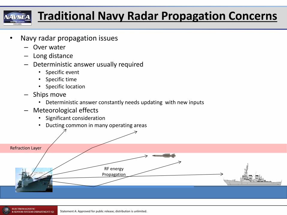
Traditional Navy Radar Propagation Concerns
• Navy radar propagation issues – Over water – Long distance – Deterministic answer usually required
• Specific event • Specific time • Specific location
– Ships move • Deterministic answer constantly needs updating with new inputs
– Meteorological effects • Significant consideration • Ducting common in many operating areas
RF energy Propagation
Refraction Layer

Statement A: Approved for public release; distribution is unlimited.
Primary Navy Radar Propagation Model
• Advanced Refractive Effects Prediction System (AREPS) – Uses Advanced Propagation Model (APM)
• Hybrid split-step Fourier Parabolic Equation / Ray Optics • 2-D vertical plane solution from transmitter to receiver
– Up to 10km high & 400km long
• “Marches” the field solution in range at multiple Rx Heights
– Designed as an “Operational Model” • Computationally efficient for fast answers • Uses approximations and empirical models vice more rigorous methods where error is minimal • Despite the above, has proven to be accurate enough for many scientific applications
– Pros • Deterministic • Can incorporate detailed local meteorological effects (past actual and forecast) • Refraction, diffraction and reflection (one) • Good with long singular, bent paths • Handles terrain (Digital terrain Elevation Data (DTED)) • Can vary surface conductivity along propagation path
– Cons • Deterministic • Does not account for vegetation • Does not account for man-made structures • 2D Vertical plane
– No horizontal diffractions, refractions, or reflections – No multi-path
• Quantized results
Statement A: Approved for public release; distribution is unlimited.
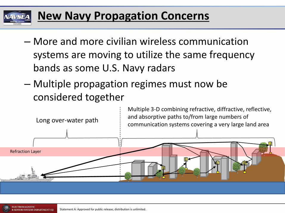
New Navy Propagation Concerns
Refraction Layer
– More and more civilian wireless communication systems are moving to utilize the same frequency bands as some U.S. Navy radars
– Multiple propagation regimes must now be considered together
Long over-water path
Multiple 3-D combining refractive, diffractive, reflective, and absorptive paths to/from large numbers of communication systems covering a very large land area
Statement A: Approved for public release; distribution is unlimited.
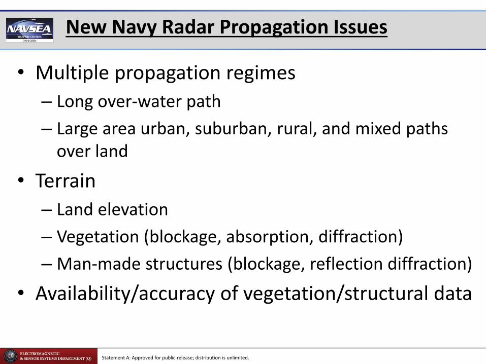
New Navy Radar Propagation Issues
• Multiple propagation regimes
– Long over-water path
– Large area urban, suburban, rural, and mixed paths over land
• Terrain
– Land elevation
– Vegetation (blockage, absorption, diffraction)
– Man-made structures (blockage, reflection diffraction)
• Availability/accuracy of vegetation/structural data
Statement A: Approved for public release; distribution is unlimited.
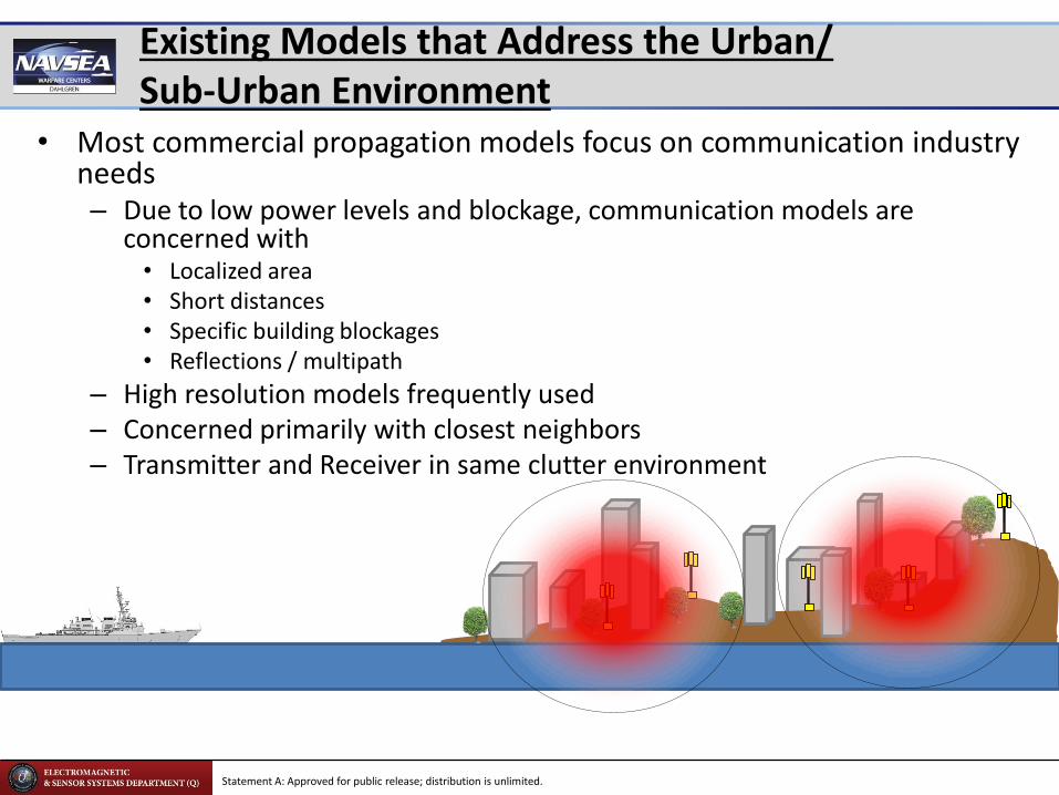
Existing Models that Address the Urban/ Sub-Urban Environment
• Most commercial propagation models focus on communication industry needs – Due to low power levels and blockage, communication models are
concerned with • Localized area • Short distances • Specific building blockages • Reflections / multipath
– High resolution models frequently used – Concerned primarily with closest neighbors – Transmitter and Receiver in same clutter environment

Statement A: Approved for public release; distribution is unlimited.
Communication Focused Models May Not Scale
– High radar antenna gain/power and wide dispersion ensures that a large area must be considered and modeled accurately
– The distance between towers is small compared to the total propagation path
• Many communication systems exposed to similar power levels • Works in reverse – many communication systems will aggregate power at
the ship location
– High fidelity models may break down or be computationally unfeasible over large distances or areas

Statement A: Approved for public release; distribution is unlimited.
Previous Attempt at Combining Methods
• A Navy program attempted to develop a combined propagation solution to a similar scenario
– One model for the initial long propagation path
• 2-D Ray tracing
• Vegetation and structures
– A second model for the 3-D multipath environment beginning at the edge of an urban/suburban area
• Used the output of the first model for excitation source
• 3-D ray tracing
Statement A: Approved for public release; distribution is unlimited.
Problems With Previous Attempt at Combining Methods
• Models used were commercial – Developed for the communications industry
– “Long distance” 2-D Vertical Plane simulations were not long enough
• Runs went well beyond the intended or validated distances of the software
– Attempts to use a full 3-D simulation over the entire area of interest was judged to be beyond current computing ability
• Accuracy of structural and vegetation data were referenced as reasons for poor agreement between the model’s predictions and measured data

Statement A: Approved for public release; distribution is unlimited.
Possible Use of Empirical/Statistical Values
• Estimates for “urban clutter” could be used in place of rigorous computation – Benefits
• Much faster • Would not require high-dollar computational systems • Could be “accurate enough” when averaged over many
systems
– Concerns • What are good values? • What is the appropriate statistical variation? • What factors need to be considered?
– Building materials – City layout – Average building height
• How to validate?

Statement A: Approved for public release; distribution is unlimited.
Other factors to Consider – Appropriate Methods
• Navy radar emissions are nearly plane waves before contacting the first object
• Since the wave is much larger than the object (buildings, etc.), it wraps around the structure and the wave reforms – Blockage effect may be less then predicted
by some computational methods
• Wave front from transmitters close to blocking structures still spherical – Are diffraction effects reciprocal?
Statement A: Approved for public release; distribution is unlimited.
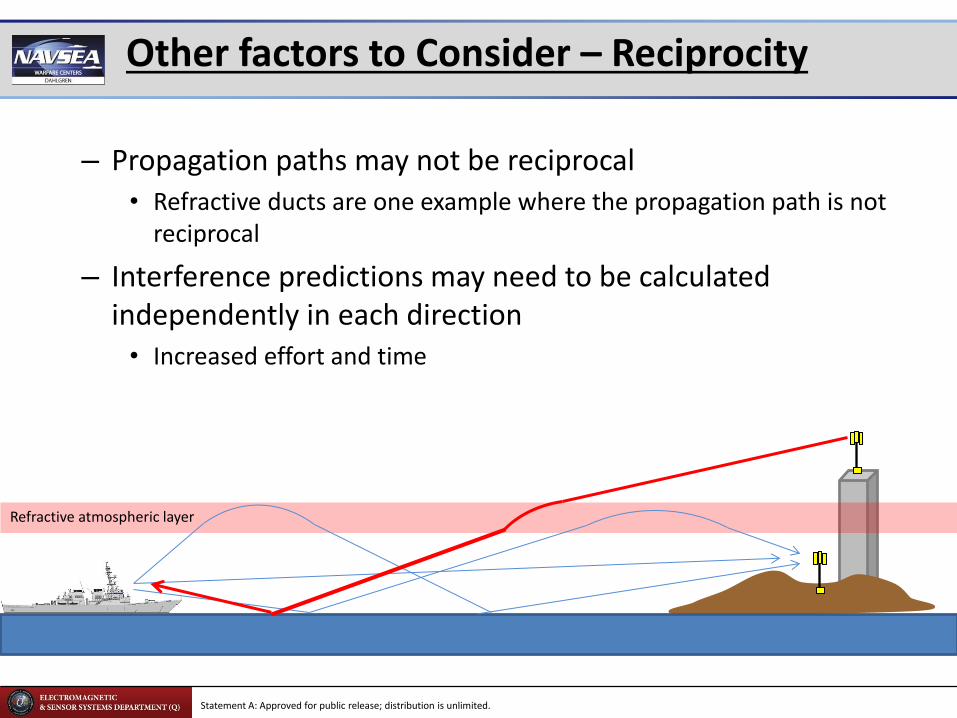
Other factors to Consider – Reciprocity
Refractive atmospheric layer
– Propagation paths may not be reciprocal • Refractive ducts are one example where the propagation path is not
reciprocal
– Interference predictions may need to be calculated independently in each direction
• Increased effort and time
Statement A: Approved for public release; distribution is unlimited.
Conclusion
• Current models appear insufficient to accurately account for long distance paths over multiple propagation regions
• Current, readily available computational capabilities are still insufficient to run high fidelity models over long distances – Even if possible, the accuracy of input data is a
concern
• Exact computations could be replaced by representative, empirical, or statistical estimates (i.e. urban clutter loss) – Consensus on values and validation required

Statement A: Approved for public release; distribution is unlimited.
BACK-UPS
Statement A: Approved for public release; distribution is unlimited.
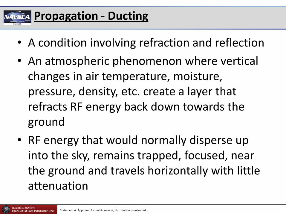
Propagation - Ducting
• A condition involving refraction and reflection
• An atmospheric phenomenon where vertical changes in air temperature, moisture, pressure, density, etc. create a layer that refracts RF energy back down towards the ground
• RF energy that would normally disperse up into the sky, remains trapped, focused, near the ground and travels horizontally with little attenuation

Statement A: Approved for public release; distribution is unlimited.
Ducting
• Meteorologists combine air temp, moisture, etc. into a single factor called M-units
• These can be plotted to show the change in relation to height above the ground/sea
• A “standard” atmosphere is linearly increasing with height • A reversal in M-units creates a super-refracting layer, which can create a duct
Standard Atmosphere
Ducting conditions
Super-Refractive atmospheric layer
Duct
RF energy Propagation
Statement A: Approved for public release; distribution is unlimited.
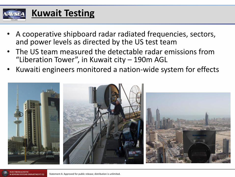
Kuwait Testing
• A cooperative shipboard radar radiated frequencies, sectors, and power levels as directed by the US test team
• The US team measured the detectable radar emissions from “Liberation Tower”, in Kuwait city – 190m AGL
• Kuwaiti engineers monitored a nation-wide system for effects
Statement A: Approved for public release; distribution is unlimited.
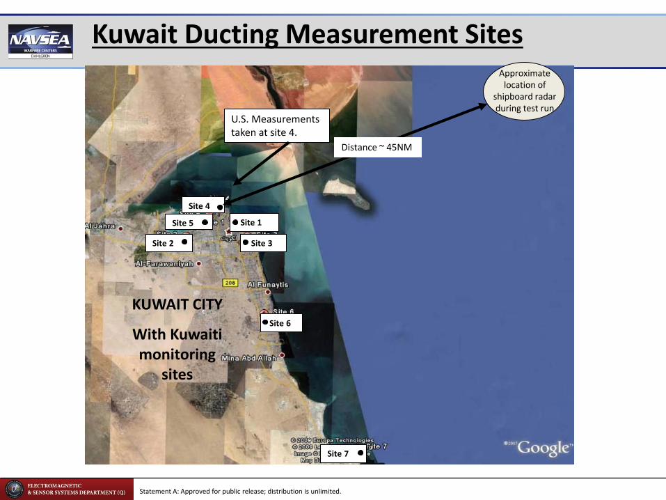
Kuwait Ducting Measurement Sites
Site 1
Site 4
Site 5
Site 2
Site 6
Site 7
Site 3
KUWAIT CITY
With Kuwaiti monitoring
sites
Approximate location of
shipboard radar during test run
U.S. Measurements taken at site 4.
Distance ~ 45NM

Statement A: Approved for public release; distribution is unlimited.
Uncorrected Kuwait Measurements
• It appears from the raw data that on different days, the same amount of radar energy caused significantly different results
1
2
3
4
5
6
-105.00 -100.00 -95.00 -90.00 -85.00 -80.00 -75.00
9-Mar 10-Mar 11-Mar
(Power levels corrected to what a 0 dBi
antenna would receive in a 7MHz BW)
Trend of System Effect as a Function of Measured Radar Power Levels
Average Measured Radar Power (dBm/7MHz)

Statement A: Approved for public release; distribution is unlimited.
(AREPS model output from actual weather data)
Ducting During Kuwait Testing
• The majority of sites saw power up to 50 dB (100,000 times) stronger on one day just due to ducting
• The difference in power received between the measurement site and the other sites varied 30 dB (a factor of 1000) over three days due to the height difference.
RF Propagation for 11 Mar ’09
Site 4 receives up to 10dB more Radar power than all
other towers
Site 4
All other sites
50
0
100
150
200
250
0 10 30 40 50 20
Range (NM)
RF Propagation for 10 Mar ’09
Site 4 receives approximately the same Radar power as
all other towers
Range (NM)
Site 4
All other sites
50
0
100
150
200
250
0 10 30 40 20 50
RF Propagation for 9 Mar ’09
Site 4 receives 10 to 20dB less Radar power than all
other towers
Site 4
All other sites
50
0
100
150
200
250
50
0 10 30 40 50 20
Range (NM)
Heig
ht
(m)
RF propagation at 1200 Local, 9 Mar ‘09 RF propagation at 1600 Local, 9 Mar ‘09
Expected RF propagation
(meteorological effects not accounted for) RF propagation at 1200 Local, 9 Mar ‘09 RF propagation at 1600 Local, 9 Mar ‘09Expected RF propagation
(meteorological effects not accounted for)
“Standard” Atmosphere Site 4
All other sites
Statement A: Approved for public release; distribution is unlimited.
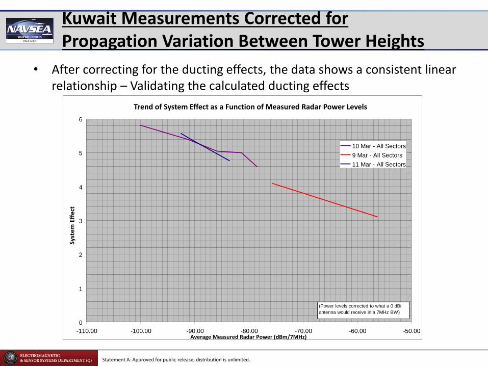
Kuwait Measurements Corrected for Propagation Variation Between Tower Heights
• After correcting for the ducting effects, the data shows a consistent linear relationship – Validating the calculated ducting effects
0
1
2
3
4
5
6
-110.00 -100.00 -90.00 -80.00 -70.00 -60.00 -50.00
10 Mar - All Sectors
9 Mar - All Sectors
11 Mar - All Sectors
(Power levels corrected to what a 0 dBi
antenna would receive in a 7MHz BW)
Average Measured Radar Power (dBm/7MHz)
Trend of System Effect as a Function of Measured Radar Power Levels