navy diesel engine inspector handbook part 1
DESCRIPTION
Marine HandbookTRANSCRIPT

S9233-CJ-HBK-010 0920-LP-118-1600 S9233-CJ-HBK-01F
U. S. NAVY DIESEL ENGINE INSPECTOR HANDBOOK
PART 1 INSPECTION PROCEDURES
DISTRIBUTION STATEMENT B: DISTRIBUTION AUTHORIZED TO U. S. GOVERNMENT AGENCIES ONLY; THIS PUBLICATION IS REQUIRED FOR OFFICIAL USE OF ADMINISTRATIVE OR OPERATIONAL PURPOSES: (DATE OF PUBLICATION, 15 NOV 1996). OTHER REQUESTS MUST BE REFERRED TO THE NAVAL SEA SYSTEMS COMMAND (SEA-09T). WARNING: THIS DOCUMENT CONTAINS TECHNICAL DATA WHOSE EXPORT IS RESTRICTED BY THE ARMS EXPORT CONTROL ACT (TITLE 22, U.S.C. 2751 ET. SEQ) OR EXECUTIVE ORDER 12470. VIOLATIONS OF THESE EXPORT LAWS ARE SUBJECT TO SEVERE CRIMINAL PENALTIES. DESTRUCTION NOTICE: DESTROY BY ANY METHOD THAT WILL PREVENT DISCLOSURE OF CONTENTS OR RECONSTRUCTION OF THIS DOCUMENT.
PUBLICATION BY DIRECTION OF COMMANDER, NAVAL SEA SYSTEMS COMMAND
30 NOV 1988
CHANGE F 30 Oct 2002

RECORD OF CHANGES
CHANGE RECORD
CHANGE NUMBER
DATE TITLE AND/OR BRIEF DESCRIPTION
SIGNATURE
A 28 JUN 91 DELETED THE WORDS “AND CALIBRATED” FROM ITEM 12-A ON PAGE D8-6
B 17 JUL 91 ADDED ISOTTA FRASCHINI INSPECTION
C 15 OCT 91 ADDED INSPECTION CRITERIA FOR FAIRBANKS-MORSE AUXILIARY DRIVE GEARS
D 15 NOV 96 NUMEROUS CHANGES, ALL EFFECTED PAGES MARKED WITH CHANGE (D). HANDBOOK PRINTED IN ITS ENTIRETY WITH ALL CHANGES.
NSWCCD-SSES CODE 9325
E 03 MAR 01 TO ADD PARAGRAPH ON TOLERANCE MEASUREMENT DATA TO CHAPTER 3
NSWCCD-SSES CODE 9441
F 15 JUN 02 ADDED INSPECTION CRITERIA FOR MTU MODEL 396TE94 AND THE CATERPILLAR MODEL 3100 DIESEL ENGINES. UPDATED THE SECURED INSPECTION SHEET FOR THE PC 2.5 MPDE. DELETED ADMINISTRATIVE DISCREPANCY DATA SHEET. VARIOUS OTHER CHANGES WERE MADE, ALL EFFECTED PAGES MARKED WITH CHANGE (E). HANDBOOK PRINTED IN ITS ENTIRETY.
NSWCCD-SSES CODE 9325
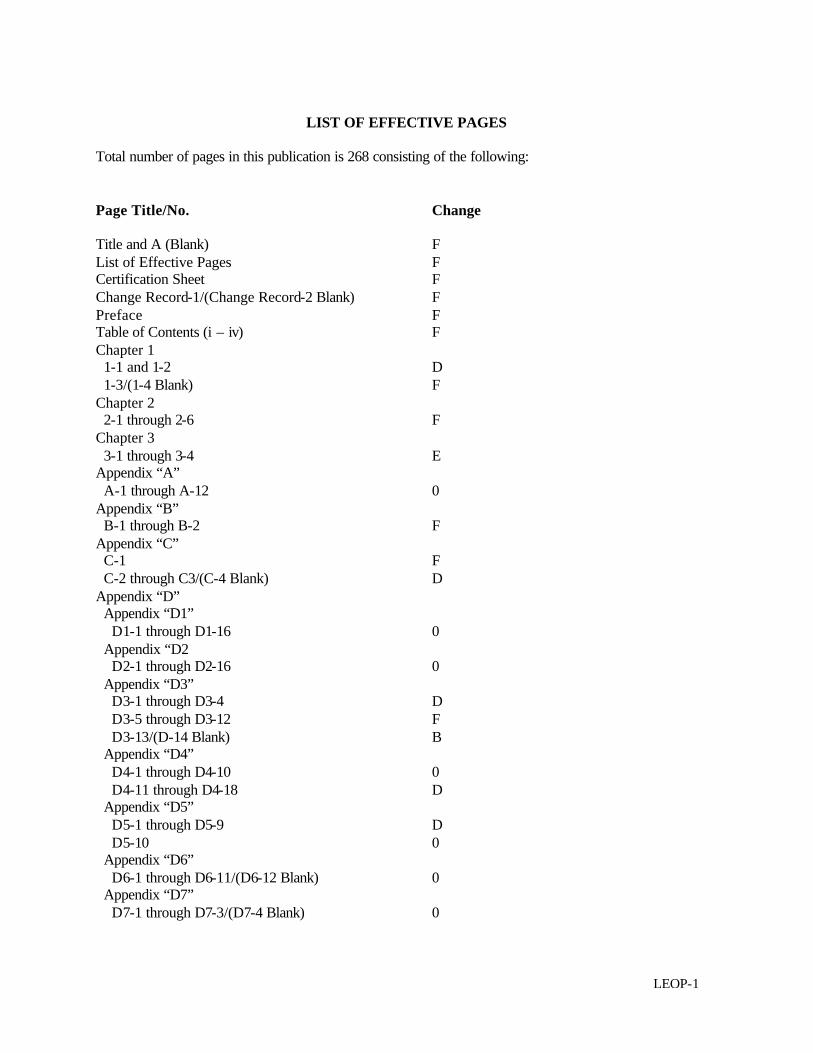
LIST OF EFFECTIVE PAGES
Total number of pages in this publication is 268 consisting of the following: Page Title/No. Change Title and A (Blank) F List of Effective Pages F Certification Sheet F Change Record-1/(Change Record-2 Blank) F Preface F Table of Contents (i – iv) F Chapter 1 1-1 and 1-2 D 1-3/(1-4 Blank) F Chapter 2 2-1 through 2-6 F Chapter 3 3-1 through 3-4 E Appendix “A” A-1 through A-12 0 Appendix “B” B-1 through B-2 F Appendix “C” C-1 F C-2 through C3/(C-4 Blank) D Appendix “D” Appendix “D1” D1-1 through D1-16 0 Appendix “D2 D2-1 through D2-16 0 Appendix “D3” D3-1 through D3-4 D D3-5 through D3-12 F D3-13/(D-14 Blank) B Appendix “D4” D4-1 through D4-10 0 D4-11 through D4-18 D Appendix “D5” D5-1 through D5-9 D D5-10 0 Appendix “D6” D6-1 through D6-11/(D6-12 Blank) 0 Appendix “D7” D7-1 through D7-3/(D7-4 Blank) 0
LEOP-1

LIST OF EFFECTIVE PAGES (CONTD).
Appendix “D8” D8-1 through D8-5 0 D8-6 A D8-7 and D8-8 0 Appendix “D9” D9-1 through D9-9/(D9-10 Blank) 0 Appendix “D10” D10-1 through D10-9/(D10-10 Blank) D Appendix “D11” D11-1 through D11-8 D Appendix “D12” D12-1 through D12-9/(D12-10 Blank) D Appendix “D13” D13-1 through D13-6 F Appendix “D14” D14-1 through D14-4 F Appendix “E” E-1/(E-2 Blank) 0 Appendix “F” Appendix “F1” F1-1/(F1-2 Blank) F Appendix “G” Appendix “G1” G1-1 F G1-2 0 G1-3/(G1-4 Blank) F Appendix “G2” G2-1 and G2-2 0 Appendix “G3” G3-1 and G3-4 F Appendix “G4” G4-1 F G4-2 through G4-3/(G4-4 Blank) 0 Appendix “G5” G5-1 and G5-2 D Appendix “G6” G6-1/(G6-2 Blank) 0 Appendix “G7” G7-1 and G7-2 0 Appendix “G8” G8-1/(G8-2 Blank) 0 Appendix “G9” G9-1/(G9-2 Blank) 0
LEOP-2

LIST OF EFFECTIVE PAGES (CONTD).
Appendix “G10” G10-1/(G10-2 Blank) D Appendix “G11” G11-1 and G11-2 D Appendix “G12” G12-1/(G12-2 Blank) D Appendix “G13” G13-1/(G13-2 Blank) F Appendix “H” Appendix “H1” H1-1 and H1-2 0 Appendix “H2” H2-1 and H2-2 0 Appendix “H3” H3-1 and H3-2 0 Appendix “H4” H4-1 and H4-2 0 Appendix “H5” H5-1 and H5-2 0 Appendix “H6” H6-1/(H6-2 Blank) 0 Appendix “H7” H7-1 and H7-2 0 Appendix “H8” H8-1 and H8-2 0 Appendix “H9” H9-1/(H9-2 Blank) 0 Appendix “H10” H10-1/(H10-2 Blank) D Appendix “H11” H11-1 and H11-2 D Appendix “H12” H12-1 and H12-2 D Appendix “H13” H13-1 and H13-2 F Appendix “H14” H14-1/(H14-2 Blank) F Appendix “I” I-1 through I-12 0 * ZERO in Change column indicates original issue.
LEOP-3


PREFACE This is the U. S. NAVY DIESEL ENGINE INSPECTOR HANDBOOK. OPNAVINST 9220.3 as the Primary procedural and administrative specification when performing Diesel Engine Inspections requires this handbook. This handbook is to be used as the Definitive Document for all Diesel Engine Inspections. The Type Commander or the Type Commander representative shall forward the Diesel Engine Inspection Report specified herein for forwarding to the Commanding Officer of the inspected ship/command. The Diesel Inspection Report will be forwarded as an enclosure to a cover letter. The cover letter may include an assigned grade and required action as specified by the Type Commander instruction(s). The intent of the Diesel Inspection Report is to advise on the Material Condition of the subject Diesel Engine and its support systems and to make corrective recommendations. This handbook is divided into two parts: Part I will provide you, the Diesel Inspector, with the requirements and procedures for properly conducting a Diesel Engine Inspection. Part II will give you a background on the design, construction, operation, and maintenance of the various Diesel Engines in naval shipboard use. Part II is not intended to replace or duplicate any specific Diesel Engine technical manual, NSTM, or operational procedure. It is intended to provide you with a technical resource that enables you to better understand and evaluate Diesel Engines and their related systems. Address any comments, questions, or changes regarding this handbook to: DEPARTMENT OF THE NAVY COMMANDING OFFICER ATTN: CODE 9325 NSWCCD-SSES 5001 S BROAD ST PHILADELPHIA PA 19112-5083 PHONE: DSN: 443-7279, 7278 COMMERCIAL: 215-897-7279, 7278 FACSIMILE: 215-897-8109, DSN: 443-8109
Preface

TABLE OF CONTENTS
Chapter/Paragraph Page
1 ROLE OF THE INSPECTOR ..................................................................................1-1 1-1 GENERAL INFORMATION ...........................................................................1-1 1-2 SAFETY .........................................................................................................1-2 1-3 LEADERSHIP.................................................................................................1-2 1-4 TRAINING .....................................................................................................1-2 2 DIESEL INSPECTION PROCEDURES .................................................................2-1 2-1 GENERAL INFORMATION ...........................................................................2-1 2-2 PRE-INSPECTION PREPARATION AND ARRIVAL MEETING..................2-2 2-3 SAFETY PRECAUTIONS ..............................................................................2-3 2-4 SPECIAL TOOLS ..........................................................................................2-3 2-5 INSPECTION SEQUENCE ............................................................................2-3 2-5.1 PHASE 1 - Administrative Review .......................................................2-4 2-5.2 PHASE 2 - Secured Inspection .............................................................2-5 2-5.3 PHASE 3 - Operational Inspection ........................................................2-5 3 THE DIESEL INSPECTION REPORT ...................................................................3-1 3-1 GENERAL INFORMATION ...........................................................................3-1 3-2 REPORT CONTENTS …………………………………………………... .........3-1 3-2.1 Cover Letter ........................................................................................3-1 3-2.2 Diesel Inspection Data Sheet ................................................................3-2 3-2.3 Discrepancy Data Sheets .....................................................................3-2 A OPNAV INSTRUCTION ..........................................................................................A-1 B REFERENCE LIST ..................................................................................................B-1 C ADMINISTRATIVE PHASE REVIEW WORK SHEET ........................................C-1 D1 ALCO DIESEL ENGINES SECURED PHASE INSPECTION
WORK SHEET .........................................................................................................D1-1 D2 EMD DIESEL ENGINES SECURED PHASE INSPECTION
WORK SHEET .........................................................................................................D2-1
D3 FAIRBANKS MORSE DIESEL ENGINES SECURED PHASE INSPECTION WORK SHEET ................................................................................D3-1
D4 COLT PIELSTICK DIESEL ENGINES SECURED PHASE
INSPECTION WORK SHEET ...............................................................................D4-1
i Change F

TABLE OF CONTENTS (Continued) D5 DDA 16V-149 DIESEL ENGINES SECURED PHASE INSPECTION
WORK SHEET..........................................................................................................D5-1 D6 SMALL, HIGH SPEED DIESEL ENGINES SECURED PHASE
INSPECTION WORK SHEET .................................................................................D6-1 D7 GENERIC, MEDIUM SPEED DIESEL ENGINES SECURED PHASE
INSPECTION WORK SHEET .................................................................................D7-1 D8 CATERPILLAR DIESEL ENGINES SECURED PHASE INSPECTION WORK SHEET .........................................................................................................D8-1 D9 WAUKESHA DIESEL ENGINES SECURED PHASE INSPECTION WORK SHEET..........................................................................................................D9-1 D10 ISOTTA FRASCHINI DIESEL ENGINES SECURED PHASE
INSPECTION WORK SHEET ................................................................................D10-1 D11 PAXMAN VALENTA DIESEL ENGINES SECURED PHASE
INSPECTION WORKSHEET .................................................................................D11-1 D12 CATERPILLAR MODEL 3608 DIESEL ENGINES SECURED PHASE
INSPECTION WORK SHEET ………………………………………………… .........D12-1 D13 MTU MODEL 396TE94 DIESEL ENGINES SECURED PHASE
INSPECTION WORK SHEET .................................................................................D13-1 D14 CATERPILLAR MODEL 3100 DIESEL ENGINES SECURED PHASE
INSPECTION WORK SHEET ................................................................................D14-1 E DIESEL INSPECTION DATA SHEET ....................................................................E1-1 F1 DIESEL ENGINE DISCREPANCY DATA SHEET.................................................F1-1 G1 ALCO DIESEL ENGINES TOLERANCE MEASUREMENT DATA SHEET ..........................................................................................................G1-1 G2 EMD DIESEL ENGINES TOLERANCE MEASUREMEN DATA SHEET ..........................................................................................................G2-1 G3 FAIRBANKS MORSE DIESEL ENGINE TOLERANCE MEASUREMENT DATA SHEET ...........................................................................G3-1
ii

TABLE OF CONTENTS (Continued)
G4 COLT-PIELSTICK DIESEL ENGINES TOLERANCE MEASUREMENT DATA SHEET ...........................................................................G4-1 G5 DDA 16 V 149 DIESEL ENGINES TOLERANCE MEASUREMENT
DATA SHEET ..........................................................................................................G5-1 G6 SMALL, HIGH SPEED DIESEL ENGINES TOLERANCE
MEASURMENT DATA SHEET ............................................................................G6-1 G7 GENERIC, MEDIUM SPEED DIESEL ENGINES TOLERANCE MEASUREMENT DATA SHEET ……………………………………………... ........G7-1 G8 CATERPILLAR MODELS, D399, D398, D397, AND D353 DIESEL ENGINES TOLERANCE MEASUREMENT DATA SHEET ………………..........G8-1 G9 WAUKESHA DIESEL ENGINES TOLERANCE MEASUREMENT DATA SHEET ..........................................................................................................G9-1 G10 ISOTTA FRASCHINI DIESEL ENGINES TOLERANCE MEASUREMENT DATA SHEET ...........................................................................G10-1
G11 PAXMAN VALENTA DIESEL ENGINES TOLERANCE MEASUREMENT DATA SHEET ...........................................................................G11-1 G12 CATERPILLAR MODEL 3608 DIESEL ENGINES TOLERANCE
MEASUREMENT DATA SHEET ...........................................................................G12-1 G13 MTU MODEL 396TE94 DIESEL ENGINES TOLERANCE
MEASUREMENT DATA SHEET ...........................................................................G13-1 H1 ALCO DIESEL ENGINES OPERATIONAL TEST DATA SHEET .......................H1-1 H2 EMD DIESEL ENGINES OPERATIONAL TEST DATA SHEET ........................H2-1 H3 FAIRBANKS MORSE DIESEL ENGINES OPERATIONAL TEST DATA SHEET ..........................................................................................................H3-1 H4 COLT-PIELSTICK DIESEL ENGINES OPERATIONAL TEST
DATA SHEET ..........................................................................................................H4-1 H5 DDA 16V 149 DIESEL ENGINES OPERATIONAL TEST DATA SHEET ..........H5-1 H6 SMALL, HIGH SPEED DIESEL ENGINES OPERATIONAL TEST DATA SHEET ..........................................................................................................H6-1
iii Change F

TABLE OF CONTENTS (Continued) H7 GENERIC, MEDIUM SPEED DIESEL ENGINES OPERATIONAL TEST DATA SHEET................................................................................................. H7-1 H8 CATERPILLAR MODELS D399, D398, D397 AND D353 DIESEL ENGINES OPERATIONAL TEST DATA SHEET .................................................H8-1 H9 WAUKESHA DIESEL ENGINES OPERATIONAL TEST DATA SHEET ..........................................................................................................H9-1 H10 ISOTTA FRASCHINI DIESEL ENGINES OPERATIONAL TEST DATA SHEET ..........................................................................................................H10-1 H11 PAXMAN VALENTA DIESEL ENGINES OPERATIONAL TEST DATA SHEET ..........................................................................................................H11-1 H12 CATERPILLAR MODEL 3608 DIESEL ENGINES OPERATIONAL TEST DATA SHEET ................................................................................................H12-1 H13 MTU MODEL 396TE94 DIESEL ENIGNE OPERATIONAL TEST
DATA SHEET ...........................................................................................................H13-1 H14 CATERPILLAR 3100 SERIES DIESEL ENGINES OPERATIONAL TEST DATA SHEET ...............................................................................................H14-1 I SAMPLE DIESEL ENGINE INSPECTION REPORT ...........................................I-1
iv

CHAPTER 1
ROLE OF THE INSPECTOR
1-1 GENERAL INFORMATION Your duties as a Diesel Inspector dictate that you display the highest diplomacy. The crew often perceives the inspector as “someone who can place me on report". To serve the ship, always try to portray yourself as “Someone Who Is Here To Help". Let your professionalism show – in your bearing, your uniform, your manner, your attitude. Remember, you may be inspecting the engine, but the crew is inspecting you. Show courtesy to the ship by planning your inspection. If you communicate with the ship, give the crew a plan of action before your arrive, you will avoid the unexpected in scheduling. Showing up on the quarterdeck to inspect the diesel engine with no prior planning, however, will always start the process badly. Do your homework before you go on board. No one can master every engine the Navy uses, but if you are well prepared to inspect a particular engine your knowledge will be apparent to the ship’s engineering department and will instill in them the confidence that you know what you’re doing. You may be a very competent inspector with good understanding of diesel engine theory, but if you don’t know, for example, the compression or firing pressure of a particular engine you have to inspect, you had better give yourself a few hours of careful preparation before you begin your inspection. Take Notes when you do your research; take them on board with you; and, most important, use them: You will gain the confidence of the crew and help yourself. If you know the limits of an engine you can do a better job of gathering data. If you know what the compression is supposed to be and the reading fall outside the specifications, you’ll be able to identify the problem immediately. No matter how through your inspection is, it will be disregarded if your data are incomplete or inaccurate. Your role as an inspector will be diverse. It will involve: • Conducting formal inspections • Responding to requests for technical assistance • Evaluating engines or systems either by shipboard visits or by phone conferences • Assisting other naval activities in diesel engine related quality assurance issues • Conducting training sessions for ship’s force on topics like diesel operation, maintenance, engine
performance tests, water treatment, lube oil analysis program and other diesel engine related subjects.
• However varies your role as an inspector might be, you must be aware that although inspecting
the engine properly is your highest priority, you must also set the standard for:
1-1

• Safety • Leadership • Training 1-2 SAFETY It is not enough to set a good example for safety. You must do as you say. This means that you do not cut corners on safety, those whom you inspect will do the same after you have completed the inspection and have left the ship. Because they view you as the expert, the crewmembers will conclude that if the inspector does it this way and cuts corners, it’s acceptable for them to do the same. Display the right example by being familiar with and following current safety practices. 1-3 LEADERSHIP As a diesel inspector you must realize your position of leadership within the diesel engine community. You should be able to evaluate any engine problem, identify the corrective action needed, and provide the necessary guidance to implement the corrective action. To accomplish this you need a thorough knowledge of the engine and its installation. This will enable you to lead the ship’s crew and will increase its confidence in your ability to manage the course of the inspection/investigation. Since you, the inspector, are constantly exposed to the fleet’s diesel engines, you are in the leadership position and can set an example for the crew in making recommendations and identifying errors in published procedures. Failure to question any area of concern permits erroneous data or procedures to affect the fleet’s diesel engines. The Navy’s diesel engine population can be improved materially by the leadership the diesel engine inspector provides to the fleet as the eyes and ears of NAVSEA the LCM, the Type Commander and the technical community. 1-4 TRAINING Inspecting an engine is only half the job. Teaching and training the crew is equally important. You will often find that the younger sailors don’t know what the inside of their engine looks like. They are eager to learn and are interested in what you do and what you know. Explain in detail what you are looking for, how to look at various components, and how to determine that one part is normal and another part isn’t. Explain why you’re taking a measurement. Don’t leave the impression that “it’s because PMS requires it.” Show the crew how to take the measurements and then have the crew take them. Don’t teach short cuts. Obtain the appropriate PMS MRC and take measurements exactly according to the procedures. Once you have demonstrated a measurement procedure or a maintenance action, the ship’s force will know how to perform the maintenance action correctly. Insist that the crew use PMS and the engine technical manual during the inspection. Show by example that the ship’s force need not be embarrassed about using the technical manual. Always strive to leave the crew with a better understanding of how to operate and maintain the engine than it had when you came aboard. 1-2
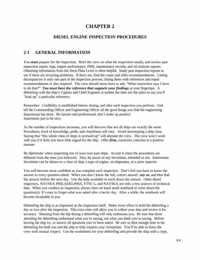
CHAPTER 2
DIESEL ENGINE INSPECTION PROCEDURES 2-1 GENERAL INFORMATION You must prepare for the inspection. Brief the crew on what the inspection entails, and review past inspection report, logs, engine performance, PMS, maintenance records, and oil analysis reports. Obtaining information from the Deck Plate Level is often helpful. Study past inspection reports to see if there are recurring problems. If there are, find the cause and offer recommendations. Listing discrepancies is only one part of the inspection process; listing them with references and repair recommendations is also required. The crew should never have to ask, “What instruction says I have to do that?” You must have the reference that supports your findings at your fingertips. A debriefing with the ship’s Captain and Chief Engineer is neither the time nor the place to say you’ll “look up” a particular reference. Remember: Credibility is established before; during, and after each inspection you perform. And tell the Commanding Officer and Engineering Officer all the good things you find the engineering department has done. Be sincere and professional; don’t make up positive Statements just to be nice. As the number of inspections increases, you will discover that not all ships are exactly the same. Procedures, level of knowledge, pride, and cleanliness will vary. Avoid stereotyping a ship class. Saying that “this whole class of ships is screwed up” will alienate the crew. The crew won’t work with you if it feels you have little regard for the ship. Offer firm, corrective criticism in a positive manner. Be diplomatic when inspecting one of your own past ships. Accept it when the procedures are different from the ones you followed. Also, be aware of any favoritism, intended or not. Inadvertent favoritism can be shown to a class of ship, a type of engine, ex-shipmates, or a prior superior. You will become more confident as you complete each inspection. Don’t feel you have to know the answer to every question asked. When you don’t know the full, correct answer, say so, and then find the answer before the next day. Use the help available to track down the answer. Other diesel inspectors, NAVSEA PHILADELPHIA, FTSC’s, and NAVSEA are only a few sources of technical data. When you conduct an inspection, always have on hand small notebook to write down the question(s): It’s easy to forget what was asked after a hectic day. After a while, the notebook will become invaluable to you. Debriefing the ship is as important as the inspection itself. Make every effort to hold the debriefing a day or two after the inspection. This extra time will allow you to collect your data and review it for accuracy. Shooting from the hip during a debriefing will only embarrass you. Be sure that those attending the debriefing understand what you’re saying, not what you think you’re saying. Before leaving the ship try, to answer all questions you’ve been asked. Be sure to allot enough time in the debriefing for both you and the ship to fully express your viewpoints. You’ll be able to leave the crew with mutual respect. Use the worksheets for your debriefing and provide the ship with a copy.
2-1

The inspection process is incomplete until the final report has been written, serialized, and received by the ship. Fill out the report thoroughly, remembering that usually it will be mailed to the ship. The report must be able to stand-alone. Don’t assume that the crew understands or knows what you’re referring to. Make sure the report is technically correct and grammatically correct, with attention paid both to spelling and to written procedures. Inspectors that say they’re “snipes", not “English majors", are both wrong and unprofessional. Take time to be sure that your findings are documented and that each discrepancy noted has a recommendation for repair. Long after the inspection has been completed your report will be reviewed and commented on. The inspection report is a ready reference for future technical assists and forthcoming diesel inspections. Write it accordingly. You are the written report and the written report is you. If you’re a new inspector, understand that being a good inspector does not comes overnight or with the NEC, but only through hard work and through continuously striving for Improvement. By following the standard diesel inspection procedures and providing a detailed report of diesel engine discrepancies, you can contribute significantly to the overall improvement of the diesel engine. 2-2 PRE-INSPECTION PREPARATION AND ARRIVAL MEETING Success in any project requires an individual to prepare, establish appropriate lines of communication, and plan a course of action. Performing a diesel engine inspection is no different. You must communicate with your customer. To ensure that the inspection starts off smoothly, provide a preprinted checklist either in letter or message format to the ship. Ensuring that the ship receives the checklist several days before the inspection will give those on board ample time to assemble those items you need to evaluate. The checklist should itemize but not be limited to the following:
• Lube oil test or spectrographic oil analysis records (if available). • Representative engine operating logs (list your minimum number of log sheets per
engine) • Applicable CASREP file • Past diesel inspection report (Required) • Current Ship’s Maintenance Project (CSMP) • Special tools (list the tools you want to examine).
Using such a form will reduce the time you have to wait while the crew locates the documentation and equipment. Type Commander or the Type Commanders representative should specify the format for the pre-inspection checklist. The arrival meeting on board the ship should establish the plan of action for the diesel inspection. It should include the proposed end date and a proposed schedule for debriefing the Commanding Officer. Convey to the crew that the intent of your inspection is not only to inspect the engines, but
2-2

also to provide the crew with training and any assistance required to improve the maintenance and reliability of the diesel engines. The Engineering Officer and/or Commanding Officer should be notified immediately if any major discrepancy is discovered during the inspection. The Senior EN/MM shall accompany the inspector during the inspection. 2-3 SAFETY PRECAUTIONS Crewmembers often try too hard to fill the requests of the inspector and may, in their desire to please, bypass safety procedures. The results could be catastrophic to the inspector, the ship’s force, and the engine. Remember, while on the scene you are the Chief Safety Observer. Demand of yourself and the ship’s force that all safety procedures be followed. When inspecting a diesel engine, strict adherence to safety must remain paramount. Take the time to ensure that danger tags are properly placed and that the valve/switch is in the position indicated on the respective tag. Emphasize the importance of properly deactivating the engine starting system, whether it is air, hydraulic, or electrical. In addition to normal safety procedures, observe the following precautions:
• When performing inspections, use the prescribed tools.
• If heavy parts must be removed, be sure that chain falls and straps are weight tested and tagged.
• Be conscious of barring the engine when personnel are working inside it.
• Observe approved methods for handling and disposing of treated jacket water. • If “hot work” is required, be sure that the ship has approved and posted a gas-
free/hot-work chit.
• Never allow any part of your body to pass under a large; heavy, unsupported engine part, not even for a “quick look".
2-4 SPECIAL TOOLS All special tools required for an inspection must be on board the ship. Use the PMS cards, NAVSEA technical manual, and the inspection worksheets provided in appendix D to determine if the special tools are available. Those special tools requiring calibration, such as micrometers, dial indicators, and crankshaft deflection gages, should also have a current calibration sticker indicating that they have been certified for use. Once again, do not set just a “good” example; set the right example. Use shipboard special tools and instruments, but don’t use special tools that are out of calibration for the sake of completing the inspection.
2-5 INSPECTION SEQUENCE To evaluate the engine in the safest, most consistent manner, conduct the diesel inspection in the following sequence.
2-3

1. Phase 1 - Administrative Review.
The administrative review phase shall not be graded. 2. Phase 2 - Secured Inspection 3. Phase 3 - Operational Inspection . The secured inspection phase shall determine if it is safe to proceed to the operational inspection phase. When the operational inspection phase has been completed, additional secured and operational inspection may be required to resolve concerns. KEEP TEARDOWN TO THE ABSOLUTE MINIMUM required to accomplish an adequate inspection. The diesel inspector should remove and copy engine-specific blank Secured Phase Inspection Worksheets (Appendix D), Tolerance Measurement Data sheets (Appendix G), and Operational Test Data Sheets (Appendix H) to complete during the inspection. The Administrative review discrepancies will be brought to the attention of the ship's crew during the administrative review and again during the debriefing. 2-5.1 Phase 1 - Administrative Review The administrative review will provide you with initial information about the particular engine’s performance and condition. The following items must be reviewed:
• Spectrographic oil analysis records (If available) • Engine operating logs • Current NSTM Chapter 233 Diesel Engines or NSTM on CD.
• Previous diesel inspection report (Mandatory) • Engine APL and engine technical manuals
• Special tools
• Engine Performance Data
Reviewing these records, particularly the Engine performance data, will give you insight into what to inspect during the secured and operational phases. Examine the ship’s force during this phase to ensure that they understand and how to use this information. Understanding and technical accuracy are much more important than neatness and format. Use your notebook as you progress through the administrative review, making appropriate entries. Analyze all data entries for correct or out-of-parameter readings. All data should be technically correct and should be within the limits specified by current technical documentation (PMS, engine technical manual, and EOSS). Note all unanswered questions, questionable data, or abnormal readings in your notebook so that you can find the answers during the other phases of the inspection. Administrative review remarks are not to be included in the Diesel Inspection Report, but you should provide your findings to the ship during the review and again during the ship debriefing.
2-4

NOTE Any discrepancy noted that was not corrected after a previous diesel inspection shall be identified as a recurring discrepancy. 2-5.2 Phase 2 - Secured Inspection Follow guidance and make appropriate entries on the worksheets in Appendix D to accomplish the secured inspection. The requirements specified in Appendix D represent the minimum to be accomplished in the secured phase. Keep TEARDOWN TO THE ABSOLUTE MINIMUM required. Be sure parts are available for reassembly before starting teardown. List discrepancies from the secured inspection on the Engine Discrepancy Data Sheet, Appendix F2. List tolerance measurements on the appropriate Tolerance Measurement Data Sheet, Appendix G, and tolerance discrepancies on the Engine Discrepancy Data Sheet. Secured inspection worksheets are not to be included in the Diesel Inspection Report, but should be retained by the you for your records, with a copy provided to the ship during the ship debriefing. It is essential that the inspection report indicate the “As found” condition of the engine. Corrected conditions may be indicated under “comments", repaired during the inspection. 2-5.3 Phase 3 - Operational Inspection If the secured phase inspection results indicate that no unsafe condition exists, continue the inspection to the operational phase. The operational phase of the inspection is necessary for thoroughly evaluating the engine’s condition and performance and should substantiate the findings of the secured inspection. Your conclusions are based on what you observed in the secured phase and are supported during the operational phase. The diesel engine should be able to achieve operational standards specified by the appropriate NAVSEA technical manual or the appropriate PMS performance card. Operating data such as compression and firing pressure readings should reinforce the findings of all the inspection phases. During the operational phase of the inspection, use the appropriate Engine Operational Test Data Sheet, found in Appendix H. List the discrepancies found during the operational inspection on the Engine Discrepancy Data Sheet, Appendix F2. Operational safety checks shall be completed in accordance with PMS as part of the operational phase. Conduct the operational phase of the inspection as follows: A. Main Propulsion Engines 1. Operate the engine in accordance with Engine Performance Test PMS. 2. If the Engine Performance Test PMS does not require operation at 100 percent load and
speed, conduct an additional operational test. Complete a separate Operational Test Data Sheet for each test.
B. Ship Service Diesel Generators 1. Operate the diesel generator in accordance with Engine Performance Test PMS.
2-5

2. If the Engine Performance Test PMS does not require operation at 100 percent or the maximum attainable load, conduct an additional operational test. Complete a separate Operational Test Data Sheet for each test.
C. Emergency Diesel Generators 1. Operate the engine in accordance with Engine Performance Test PMS 2. If the Engine Performance Test PMS does not require operation at 100 percent or the
maximum attainable load, conduct an additional operational test. Complete a separate Operational Test Data Sheet for each test.
Compare the results of the Operational Engine Performance Test PMS to shipboard records and list inconsistencies on the Engine Discrepancy Data Sheet, Appendix H. If Engine performance Test PMS requires 100 percent or maximum attainable load, only one operational test is required and only one operational test data sheet per engine must be completed. Otherwise, complete separate operational test data sheets for Engine Performance Test PMS and full load tests on each engine.
2-6
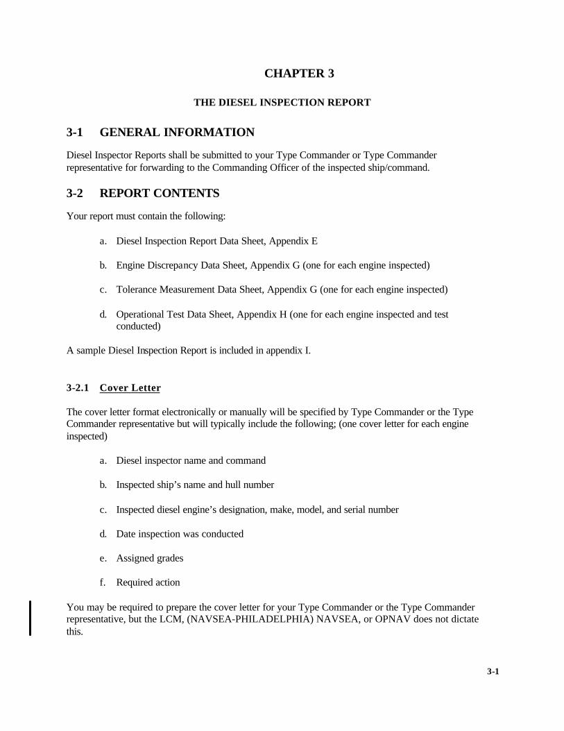
CHAPTER 3
THE DIESEL INSPECTION REPORT
3-1 GENERAL INFORMATION Diesel Inspector Reports shall be submitted to your Type Commander or Type Commander representative for forwarding to the Commanding Officer of the inspected ship/command. 3-2 REPORT CONTENTS Your report must contain the following: a. Diesel Inspection Report Data Sheet, Appendix E b. Engine Discrepancy Data Sheet, Appendix G (one for each engine inspected) c. Tolerance Measurement Data Sheet, Appendix G (one for each engine inspected) d. Operational Test Data Sheet, Appendix H (one for each engine inspected and test
conducted) A sample Diesel Inspection Report is included in appendix I. 3-2.1 Cover Letter The cover letter format electronically or manually will be specified by Type Commander or the Type Commander representative but will typically include the following; (one cover letter for each engine inspected) a. Diesel inspector name and command b. Inspected ship’s name and hull number c. Inspected diesel engine’s designation, make, model, and serial number d. Date inspection was conducted e. Assigned grades f. Required action You may be required to prepare the cover letter for your Type Commander or the Type Commander representative, but the LCM, (NAVSEA-PHILADELPHIA) NAVSEA, or OPNAV does not dictate this.
3-1
3-2.2 Diesel Inspection Report Data Sheet The Diesel Inspection Report Data Sheet, appendix E, serves as the front page of your report and provides the basic data for the inspection and the engines inspected. Include one sheet of data for each engine inspected. 3-2.3 Discrepancy Data Sheets List discrepancies found during the administrative review, secured, and operational phases of the inspection on the Administrative Review Sheets and Engine Discrepancy Sheets, Appendix F. Categorize discrepancies (column 1) as Repair Before Operation, major and minor. List all engine discrepancies noted on the Secured Phase Worksheet, Tolerance Measurement Data Sheet, Operational Test Data Sheet, and any other engine discrepancies on the Engine Discrepancy Data Sheet, Appendix F2 (a separate sheet for each engine inspected). Tolerance measurement data shall be compared with previous data. Although the data may be within maximum and minimum specifications, any measurement, which has changed 0.0025 inch or more, must be discussed on the Engine Discrepancy Data sheet. Use the “category” column in the engine discrepancy data sheets to specify the discrepancy category or severity. Discrepancies shall be Categorized in one of the categories Repair Before Operation (RBO), Major, or Minor. Repair Before Operation discrepancies include those for which continued operation could endanger personnel and/or cause serious damage to the engine or associated equipment such as but not limited to:
• Low lube oil pressure • Malfunctioning overspeed governor or trip • Inoperative alarms or safety devices
• Readings that exceed the limits of PMS or manufacturer specifications that in the
judgment of the inspector are unsafe • Uncontrollable oil leaks, NSTM Chapter 233 Diesel Engines provides guidance
for lube and fuel oil leaks.
• Fuel leaks
• Evidence of serious internal failure (bearing, connecting rod, crankshaft, or piston failure)
• Fuel dilution of lube oil of 5 percent or greater You may not demand that the engine not be operated. You may only recommend to the Commanding Officer and your Type Commander that the engine not be operated for reasons of safety. You must inform the Commanding Officer, however, that you are following the Type Commander's instructions. When you identify a “REPAIR BEFORE OPERATION “ (RBO) discrepancy notify the Commanding Officer and Engineering Officer immediately. Continue the inspection after
3-2

debriefing them on the RBO discrepancy. The Diesel Inspector should make every effort to clear the (RBO) before the completing the inspection. If you cannot clear the (RBO) make recommendations to clear the (RBO) based on current references and offer advice on personnel hazards and/or possible damage to the engine should the engine be operated before the (RBO) is cleared. The Commanding Officer, should he elect to operate the diesel engine, bears the ultimate responsibility for any personnel or machinery casualties. A certified inspector shall re-inspect all areas of the diesel engine that were categorized as “REPAIR BEFORE OPERATION”. Inspect the discrepancy and clear it if it has been properly corrected. MAJOR: discrepancies include those that require prompt action but that pose no immediate personnel or equipment hazard:
• Conditions are contrary to good engineering practice
• Air box or exhaust belt/muffler excessively dirty or oil laden
• Critical components exceeding prescribed limits (Caution: You must decide if the exceeded limits make the engine unsafe.)
• Engine unable to hold rated load
• Jacket water treatment out of specification
Categorize all other discrepancies as MINOR. The Engine Discrepancy Data Sheet “component” or “system” column should specify the faulty component or engine system that is deficient. The “description column in engine data sheets should contain a complete, concise, and accurate description of the discrepancy. This description should be as specific and quantitative as possible avoiding adjectives such as “severely: and “excessively”. Include references whenever possible. The final columns, “recommended corrective action” and “repair recommendation", should provide concise instructions on how to correct the problem, citing references. Fill in all blocks on the Operational Test Data Sheets. Mark those blocks that do not apply to the particular engine as N/A. Common mistakes on the operational data sheets are:
• Incorrectly reading of “to” and from” gage readings
• Entering information that is obviously incorrect because of defective blow-down valves
• Failing to enter compression/firing pressure readings because of defective blow-down
valves
3-3

It is essential to complete all phases and requirements of the inspection. An inspection is incomplete if you have failed to:
• Obtain all the required data for the operational phase(s). • Conduct the operational phase at specified power levels.
• Complete all phases of the inspection. • Complete the inspection within a reasonable time (Type Commander Policy). • Leave the ship without leaving behind some of your knowledge.
3-4
OPNAVINST 9220.3 N763
OPNAV INSTRUCTION 9220.3 From: Chief of Naval Operations Subj: PROPULSION AND AUXILIARY PLANT INSPECTION AND INSPECTOR
CERTIFICATION PROGRAM Ref: (a) NAVSEA S9086-GY-STM-010, Naval Ships Technical Manual, Chapter 221 – Boilers (NOTAL) (b) NAVSEA S9587-B1-MMA-010, Naval Ships Technical Manual- Catapult Steam Support Systems for CV/CVN Class Ships (NOTAL) (c) NAVSEA S9221-DZ-MMA-010, Steam Generating Plant
Inspector Manual (Non-Nuclear) (NOTAL) (d) JFFM CINCLANTFLT/CINCPACFLT INST 4790.3 (NOTAL) (e) NAVSEA S9233-CJ-HBK-010, Navy Diesel Engine Inspector Handbook (NOTAL) (f) CNET 1500/19 (Series) Catalogue of Navy Training Courses (CANTRAC) (NOTAL) 1. Purpose a. To establish policy for the inspection requirements of all U.S. Navy diesel engines, conventional steam generating plants, steam catapult accumulators, and marine gas turbine engines; and to outline command and incumbent functional area of responsibilities. b. To establish training and certification guidelines for all steam generating plant inspectors (SGPI), diesel engine inspectors (DEI) and marine gas turbine inspectors (MGTI). 2. Cancellation. OPNAVINSTs 9221.1B, 9233.1A, and 9234.1A 3. Discussion a. To maintain fleet operational capability and preclude serious personnel and material casualties, a stringent inspection program is established for all diesel engines, conventional steam generating plants, steam catapult accumulators, and marine gas turbine engines. Inspection requirements must be carefully prescribed and standardized to achieve consistency and effectiveness of inspections. b. Because of the variety and complexity of propulsion and auxiliary plants and associated support systems, certification of inspectors must be closely monitored and standardized. Emphasis at
A-1

all levels of command is required to achieve the desired standards and to maintain overall fleet readiness.
c. Steam plant pressure vessels including steam catapult accumulators must receive strength and integrity inspections and industrial inspections by the Naval Surface Warfare Center, Carderock Division – Ship Systems Engineering Station (NSWCCD-SSES), Life Cycle Engineering Manager (LCEM) inspectors, accompanied by TYCOM SGPI, in accordance with reference (a) and (b). These inspections involve areas not normally covered by SGPIs. d. Steam generating plants on leased Foreign Military Sales (FMS) ships are required to be inspected under the requirements listed herein for inspection periodicity and inspector certification. 4. Policy. All diesel engines, conventional steam generating plants, steam catapult accumulators, and marine gas turbine engines shall be given periodic standardized inspections as delineated in this instruction. To execute this policy all inspectors will perform assigned duties in accordance with their responsibilities as outlined in this instruction. Certification requirements for SGPIs, DEIs, and MGTIs are outlined in this instruction. Inspection program managers are as assigned per paragraph 8a. 5. Inspection Requirements. All diesel engines (to include main propulsion, ship service and emergency diesel generators), conventional steam generating plants (to include main propulsion, auxiliary, and waste heat boilers), steam catapult accumulators, marine gas turbine engines in U.S. Navy ships, submarines, small boats, craft and engineering school hot plant training sites shall be inspected. Inspection requirements for diesel engines on small boat and craft apply only to diesel engines 400 hp and above. Material condition of inspected equipment shall be formally documented in the respective inspection and repair management information systems. Specific requirements: a. Standardized inspection procedures and criteria must be followed. SGPIs are to follow inspection guidance provided by reference (a) through (d). DEIs are to follow inspection guidance provided by reference (d) and (e). MGTIs are to follow inspection guidance promulgated by the program manager and reference (d). b. Required periodicity for inspections to be accomplished by certified SGPIs, MGTIs or DEIs on applicable equipment is provided in Table 1. Required periodicity for inspections to be accomplished by NSWCCD-SSES LCEM inspector on boilers and catapults
A-2

is provided in Table 2. SGPI will accompany the NSWCCD-SSES LCEM inspector as delineated in Table 2. TYPE INSPECTION EQUIPMENT SCHEDULE DATE
Boiler/ Catapult (1)
§ Once during Inter-deployment Training Cycle (IDTC).
§ Normal interval 18 months § Not to exceed 24 Months. § No earlier than 12 months. § Initial within 18 Months of ship acceptance.
Diesel (2)
§ Once during Inter-Deployment Training Cycle (IDTC).
§ Not to exceed 24 months. § Normal interval 18 months § No earlier than 12 months. § Initial within 90 days of ship acceptance.
Routine
Gas Turbine § Once during IDTC. § Not to exceed 24 months. § Schedule 90 to 120 days prior to deployment. § Initial within 18 Months of ship acceptance.
Phased Maintenance Availability/ Overhaul
Gas Turbine § Optional prior to each.
Boiler/ Catapult
§ Strength & Integrity inspection support as delineated in Table 2.
Diesel (3) § Inspect prior to any unplanned overhaul. § When major malfunctions or casualties occur or
are suspected.
Other
Gas Turbine § To maintain compliance with Gas Turbine Bulletins.
(1) The Type Commander (TYCOM) SGPI normally performs routine boiler inspections during a pre-assigned time period. However, the routine boiler inspection can be accomplished in connection with the completion of availability/overhaul inspection (CAI/COI) industrial boiler inspections. The pressure vessel portion of the industrial inspection conducted by the NSWCCD-SSES LCEM inspector can be combined with the TYCOM SGPI inspectors Automatic Boiler Controls (ABC) and Boiler Water/Feed Water (BW/FW) portions to account for the routine inspection.
(2) TYCOMs may exempt diesel engines on boats and craft from the routine inspection requirement where the engine or boat configuration provides
insufficient access to accomplish inspection. (3) Technical assist or casualty inspections are not to be considered a routine inspection.
TABLE 1: DEI, MGTI, And SGPI Inspection Scheduling And
Responsibilities.
A-3

TYPE INSPECTION
EQUIPMENT
SCHEDULE DATE
SCHEDULER
Five Year Strength And Integrity (1)
Boiler/ Catapult
§ Normal interval 60 months § No earlier than 48 months § Not to exceed 72 months.
TYCOM (Coordinate with LCEM)
§ Start of Availability Overhaul (SAI/SOI) (1)
Boiler/ Catapult
§ At start of availability/ overhaul in conjunction with strength and integrity.
Naval Shipyard or SUPSHIP
Industrial Support/ Visit (ISV) (2)
Boiler only
§ During availability/overhaul. Naval Shipyard or SUPSHIP
Completion of Availability/ Overhaul (CAI/COI) (1)
Boiler/ Catapult
§ To be conducted before re-assembly of equipment and final hydrostatic test
Naval Shipyard or SUPSHIP
Newly constructed ship Acceptance Inspection
Boiler/ Catapult
§ Prior to delivery. § In conjunction with the open-
and-inspect phase of the Board of Inspection and Survey (INSURV) acceptance trials.
§ For catapult accumulators, initial strength & integrity inspection shall be accomplished 6 months after vessel is placed in service and prior to expiration of the ships guarantee period.
NAVSEA Acquisition Manager
Inactivation/ Reactivation
Boiler only
§ Prior to final action and disposition.
INACTSHIPFAC Naval Shipyard or SUPSHIP
(1) The cognizant TYCOM SGPI inspector shall accompany the NSWCCD-SSES LCEM
Inspector. (2) The Industrial Support Visit (ISV) is normally provided during major overhaul
and/or repair assignments. These ISVs may be deleted by the LCEM with TYCOM concurrence for any short duration availability or any availability with no major repair assignments.
TABLE 2: NSWCCCD-SSES LCEM Boiler/Catapult Inspection
Scheduling and Responsibility. 6. Certification Requirements. All inspector candidates (military personnel, civil service personnel, and civilian contractors) must satisfactorily complete the required and pre-requisite course(s) listed in reference (f). The pre-requisites for course attendance are as follows:
A-4
a. Military Enlisted Personnel candidates: (1) E-7 and above with 5 years experience in operation and maintenance of the applicable equipment, including at least 1 year of supervisory experience. (2) Graduate from one of the “C” schools listed in reference (f) for the applicable course to include graduation from all pre-requisite courses. (3) Commanding Officer recommendation. (4) Type Commander (TYCOM) endorsement. (5) SGPI candidates must have current certification in the Boiler Water/Feed Water Test and Treatment Supervisor's Course listed in reference (f). b. Commissioned officers assigned to Board of Inspection and Survey (INSURV) or engineering readiness and training activities may attend the inspector courses, however they shall not be certified as inspectors as delineated in this instruction. c. Civil service and civilian contractor personnel candidates: (1) A minimum of 5 years experience of general marine propulsion and/or power generation experience in operations, maintenance, repair, or inspections. A bachelor's or master’s degree in mechanical or marine engineering may be substituted for 3 of the 5 years of experience. (2) A minimum of 2 of the 5 years of experience will be in specialized marine propulsion or power generation maintenance, repair or inspection experience at the engineer, technician, planner, designer, foreman, or quality assurance level concentrating on the specific application (i.e. gas turbines, diesels, and boilers). (3) A written recommendation from the candidate’s employer verifying the candidate’s experience level. The recommendation will be submitted through the chain of command. (5) SGPI candidates must graduate from one of the “C” schools listed in reference (f) for the applicable course to include graduation from all pre-requisite courses. d. All candidates:
A-5

(1) Physically capable of entering confined areas such as boiler steam and water drums, uptakes, stacks, engine enclosures and plenums. (2) Pass a pre-test (as required) developed by the applicable inspector school, administered by a TYCOM designated representative, within 1 year prior to the commencement of the certification course. A retest may not be administered within 6 months of a prior test failure. Tests will indicate the individual's level of knowledge in applicable areas of boiler/engine theory, mechanics, system inter-relationships, automatic combustion control systems, boiler water chemistry, governor operation and the ability to diagnose/trouble shoot boiler/engine problems as applicable to the specific inspector discipline. The instructor school shall provide requested copies of the pre-test to the TYCOM for administration, grade the returned tests and provide the test results to the TYCOM. (Not required for SGPI civil service or civilian candidates). 7. Certification a. Initial Certification. The school will provide a list of all course graduates to the applicable program manager. (1) After successful completion of the SGPI school course of instruction, and upon recommendation from the appropriate school, the applicable program manager will issue a 36-month certification. (2) The program manager will issue final MGTI certification upon receipt of documentation from the appropriate Fleet Technical Support Center (FTSC) that the field portion of the course has been successfully completed. (3) Final DEI certification will be issued by the program manager upon satisfactory completion of two inspections under instruction of a certified diesel engine inspector and an endorsement from TYCOM or appropriate FTSC. b. Maintaining Certification. All certified inspectors must maintain currency in knowledge of approved inspection practices and policies. Certification will be maintained for those inspectors who comply with the following: (1) Conduct a minimum of two inspections annually. (2) Attend one seminar every year. Upon written request the program manager may grant waivers to individual inspectors who A-6

are unable to attend the seminar due to circumstances beyond their control. (3) SGPIs must maintain a current certification in Boiler Water/Feedwater Test and Treatment. c. Extending Certification. Currently certified inspectors may request to extend their initial certification or subsequent extended certification in 36-month increments provided the requirements in paragraph 7b are met. The inspector must submit a letter requesting certification extension to the appropriate program manager via the inspector’s chain of command or government activity that contracted the inspector’s services with copy to the appropriate program manager. The letter must include a brief description of the inspector's duties during the certification period, specify the date of the latest seminar attended and provide as enclosures a copy of each of the two most recent inspection reports performed by the inspector. d. Revoking Certification. All inspectors must maintain knowledge of approved inspection practices and policies. The program manager shall revoke the certification of all inspectors who fail to comply with paragraph 7b.
e. Reinstatement of an Expired/Revoked Certification. The inspector must submit a letter requesting reinstatement to the program manager via the inspector’s chain of command or government activity that contracted the inspector’s services with copy to the appropriate program manager. The letter must include a brief description of the inspector's duties during and following the certification period, and provide as enclosures a copy of each of the two most recent inspections performed by the inspector. If the certification has been expired for more than 6 months, the two inspections submitted with the reinstatement letter shall be completed under the instruction of a certified inspector.
f. Inspector Transition Between Military /Civilian Status. Inspectors may transition from military to civilian status without losing their certification. For those inspectors in transition, the certification expiration date remains as established. In all cases the requirements for maintaining certification, extending certification, and reinstatement of an expired/revoked certification are as specified in paragraphs 7b. through 7e.
A-7

8. Action a. Commander, Naval Sea System Command (COMNAVSEASYSCOM) has assigned Naval Surface Warfare Center, Carderock Division – Ship Systems Engineering Station (NSWCCD SSES) codes as SGPI (Code 922), DEI (Code 932), and MGTI (Code 933) program managers. COMNAVSEASYSCOM shall provide funding to NSWCCD SSES for responsibilities listed in paragraph 8b. b. NSWCCD SSES program managers shall: (1) Provide overall management of the DEI, SGPI and MGTI programs. (2) Provide technical support to the semi-annual seminars. Seminars allow for technical interface among Fleet units, COMNAVSEASYSCOM and field activities, FTSCs and other activities with inspection responsibilities, and are to include discussion of current inspection criteria, procedures, and problems. (3) Conduct periodic technical audits of the inspector training courses to ensure technical accuracy and adequacy. (4) Provide technical management of the inspector programs. Ensure that the required technical documentation to support the program is maintained current. Establish and monitor the requirements and standards for all diesel engines, steam generating plant, steam catapult accumulator and marine gas turbine engine inspections required by this instruction.
(5) Provide funding and program management of the inspection and associated repair management information database system. (6) Maintain the primary database of all certified inspectors by name, rating, duty station or place of employment, date of certification, and expiration date of certification. (7) Revoke inspector certification and initiate action to decertify inspectors who fail to comply with the requirements in paragraph 7b. (8) Ensure that the requirements for inspector certification are met prior to final approval. c. Fleet Commanders/TYCOM’s shall:
A-8

(1) Identify and designate those fleet activities that have inspection responsibilities and maintain a base of certified inspectors within those activities. (2) Review the guidelines and inspection requirements for all diesel engines, steam generating plant and marine gas turbine engine inspections required by this instruction. (3) Schedule and coordinate inspections required by this instruction with the appropriate technical activities. (4) For the SGPI program, ensure the availability of an appropriate school ship with a “D” type boiler with full automatic boiler controls system to support training. (5) Ensure administration and control of the TYCOM-administered pretest, as specified in paragraph 6d(2). (6) Host semi-annual inspector seminars on an alternating coast basis. (7) Provide and maintain for all inspections to be documented in the applicable inspection and repair management information database system. d. Chief of Naval Education and Training shall: (1) Be responsible for the overall training of inspectors to including designation of activities authorized to conduct training. (2) Final approval of the inspector training course plans, course materials, and training aids. (3) Develop, maintain and control pre-test as required by paragraph 6d(2). (4) Issue initial certifications and submit the appropriate documentation to assign the NEC (for military inspectors) to those inspector candidates that successfully complete the requirements in paragraph 6. Copies of the appropriate paperwork shall be forwarded to the appropriate TYCOM, FTSC and program manager. (5) The instructor school shall provide requested copies of the pre-test to the designated representatives for administration, grade the returned tests and provide the test results to the designated representatives. e. Commander, Naval Personnel Command shall:
A-9

(1) Ensure that all enlisted personnel assigned to
inspector certification instruction course billets hold the proper Navy Enlisted Classification (NEC), are currently certified, and have at least 3 years prior experience as an inspector.
(2) Assign sufficient numbers of qualified personnel to the
inspector training courses to fulfill billet requirements.
(3) Maintain billet requisitions to current Fleet manning requirements. f. Fleet Technical Support Centers (FTSC) shall: (1) Screen and endorse candidates for entry into the inspector certification programs. (2) Conduct field on-the-job training (OJT) portion of the MGTI and DEI training course. (3) Maintain the database of all local inspectors, ensuring that the appropriate program managers are forwarded this data semi-annually.
(4) Ensure that certified inspectors maintain their qualification as listed in paragraph 7b.
(5) Ensure that the requirements for inspector re-certification and certification extensions are met prior to final approval. Copies of all actions shall be forwarded to the appropriate program manager.
g. Steam Generating Plant, Marine Gas Turbine, Diesel Engine Inspectors shall: (1) Perform periodic standardized routine inspections as required by the Fleet, TYCOM, and COMNAVSEASYSCOM directives. (2) Provide troubleshooting and technical assistance to the fleet. (3) Ensure inspections are performed in accordance with the guidelines and inspection requirements of this instruction. (4) Document inspections in the applicable inspection management information system.
h. Commanding Officers shall:
A-10

(1) Nominate motivated and qualified technicians for entry into the inspector programs to their respective TYCOM. (2) Ensure assigned inspectors are afforded the opportunity to attend applicable seminars. 9. Changes. Recommended changes to this instruction shall be submitted to the cognizant program manager, Naval Surface Warfare Center, Carderock Division, Ship Systems Engineering Station, Philadelphia PA 19112-5083 - Code 922 (SGPI), Code 932 (DEI), and Code 933 (MGTI). 10. Reports. The reporting requirements contained in this directive are exempt from reports controlled by SECNAVINST 5214.2b. Distribution: SNDL A1J1F (PEO SURFACE STRIKE) A1J1L (PEO THEATER SURFACE COMBATANTS) A1J1M (PEO MUW) A1J1N (PEO SUB) A1J1P (PEO EXW) A1J1Q (PEO CARRIERS) 21A (Fleet Commanders in Chief) 24 (Type Commanders) 25A (COMINEWARCOM) 26A (Amphibious Group) 26B3 (Naval Surface Reserve Force Commander) 26E (Amphibious Unit) 26H (Naval Coastal Warfare Group) 26J (Afloat Training Group and Detachment) 26Z (Shore Intermediate Maintenance Activity) 28 (Squadron Division and Group Commanders – Ships) 29 (Warships) 31 (Amphibious Warfare Ship) 32 (Auxiliary Ships) 36 (Service Craft) 41A (Commander Military Sealift Command) 50D (COMNAVSPECWARCOM CORONADO CA) FA8 (Fleet Technical Support Center Lant) FB8 (Fleet Technical Support Center Pac) FJA3 (COMNAVPERSCOM) FKA1G (COMNAVSEASYSCOM) FKP4E (Naval Surface Warfare Center Divisions) FKP7 (Shipyard) FKP8 (Supervisor, Conversion and Repair, USN) FK4P16 (Ship Systems Engineering Station) FT1 (CNET) FT24 (Fleet Training Center)
A-11

FT30 (SERVSCOLCOM) (Add SPECWARCOM) OPNAV (N1, N3/5, N7, N75, N76, N77, N78, N79, N80, N81, N09B)
A-12

REFERENCE LIST
CINPACFLT/ CINCLANTFLT JOINT FLEET MAINTENANCE MANUAL 4790.3 Series OPNAVINST 4790.4 MAINTENANCE AND MATERIAL
MANAGEMENT SYSTEMS (3-M) SYSTEMS MANUAL
OPNAVINST 9220.3 PROPULSION AND AUXILIARY PLANT
INSPECTION AND INSPECTOR TRAINING AND CERTIFICATION PROGRAM (NON-NUCLEAR
NAVAL SHIPS TECHNICAL MANUAL CHAPTER 075 a. Lock Wiring b. Self Locking Fasteners c. Torque Charts
d. Cadmium Plated Fasteners NAVAL SHIPS TECHNICAL MANUAL CHAPTER 220 Volume 3 a. Jacket Water Treatment and Logs NAVAL SHIPS TECHNICAL MANUAL CHAPTER 233 a. Safety b. Run in Procedures c. Crankcase Pressure/Vacuum d. Manometers e. Firing Pressures f. Operating Envelope g. Operation in Drydock h. Maintenance i. Pyrometers j. Lube Oil Flushing k. Records and Reports m. Safety Precautions n. Crankcase Explosions o. Shimming p. Lube and Fuel Oil Leakage NAVAL SHIPS TECHNICAL MANUAL CHAPTER 244 a. Bearings NAVAL SHIPS TECHNICAL MANUAL CHAPTER 254 a. Zinc Maintenance
/ (B – ii Blank)
B-1

REFERENCE LIST (CONTD). NAVAL SHIPS TECHNICAL MANUAL CHAPTER 505 a. Spray Shields b. Fuel Oil Splash Plates c. Piping Identification and
Markings and Color Coding d. Pipe Hanger Adjustments e. Cooler End Bells NAVAL SHIPS TECHNICAL MANUAL CHAPTER 541 (F-76) a. Fuel Oil Stowage, Usage and Handling b. Fuel Oil Testing NAVAL SHIPS TECHNICAL MANUAL CHAPTER 543 (F-44) a. Fuel Oil Stowage, Usage and Handling b. Fuel Oil Testing NAVAL SHIPS TECHNICAL MANUAL CHAPTER 551 a. Air Flasks NAVAL SHIPS TECHNICAL MANUAL CHAPTER 631 a. Painting and Preservation NAVAL SHIPS TECHNICAL MANUAL CHAPTER 635 a. Lagging NAVSEA 0902-018-2010 General Overhaul Specifications for Deep Diving SSBN/SSN Submarines NAVSEA 0948-LP-102-2010 Fuel Oil and Lube Oil Strainer Safety Shields NAVSEA S6430-AE-TED-010/VOL 1 Flexible Hoses Hydro and Inspection NAVSEA S9AA0-AB-GOS-010/GSO General Specifications for Overhaul of Surface Ships NAVSEA S9073-AZ-HBK-010 U. S. Navy Resilient Mount Handbook TYCOM INSTRUCTIONS AS REQUIRED
B-2

ADMINISTRATIVE PHASE REVIEW WORKSHEET
NOTE:
DO NOT GRADE THE ADMINISTRATIVE PHASE REVIEW OR INCLUDE THE
WORKSHEETS AS PART OF THE DIESEL ENGINE INSPECTION REPORT. PROVIDE YOUR FINDINGS TO THE SHIP DURING THE REVIEW AND THE DEBRIEFING
USS________________________________ Date________________________________ 1. Engine APL and APL Date (Check for Configuration) Comments: __________________________________________________
NOTE:
THE DIESEL ENGINE REPORT GENERATOR (DERG) WILL DISPLAY CORRECT APL AND TECHNICAL MANUAL 2. Engine Technical Manuals Comments: ___________________________________________________ _____________________________________________________________ _____________________________________________________________ 3. Operating Logs Comments: ___________________________________________________ 4. Engine Hour Logs Comments: ___________________________________________________ 5. Planned Maintenance system, Records and Machinery History (f required) Comments: ___________________________________________________
6. Engine Performance Data (From PMS). Comments: ____________________________________________________
7. EOSS or Start-up Procedures Comments: ___________________________________________________ 8. NSTM Chapter 233 Comments: ___________________________________________________
C-1

NOTE: NSTM 'S ON CD IS ACCEPTABLE, PAPER COPY NOT REQUIRED.
9. Last Diesel Inspection Report Comments: ___________________________________________________
NOTE:
LIST DISCREPANCIES ONLY DO NOT ASSIGN A GRADE. 10. Training Records Comments: ___________________________________________________ 11. Program Status:
Engine No. Engine Performance Test Oil Analysis Records
Do not assign grade. List discrepancies only on administrative review sheet.
12. Engine Data:
Engine No. Serial No. Model No. Hrs. Since Ovhl. Hrs. Since Comm.
C-2

NOTE
If total hours since overhaul are unknown, estimate hours based on yearly usage and enter that figure for a five-year period. Also, if total engine hours since commissioning are unknown, estimate hours based on yearly usage and enter that figure times the years the engine has been in commission.
NOTE ENSURE ENGINE SERIAL NUMBERS AND MODEL NUMBERS MATCH THE DIESEL ENGINE REPORT GENERATOR (DERG) CORRECT DATA AS REQUIRED
C-3

ALCO ENGINES SECURED-PHASE INSPECTION WORKSHEET
USS_______________________________ DATE______________________________ ENGINE NO.________________________ A. SPECIAL TOOLS
NOTE
Inspect a minimum of 25 percent of the following tools. 1. Appropriate size micrometers inside and outside (0 to 10 inch). Comments: ___________________________________________ 2. Depth micrometer (0 to 3 inch). Comments: ___________________________________________ 3. Torque wrench (1/2-inch drive) (_____ft/lb). Comments: ___________________________________________ 4. Torque wrench (3/4-inch drive) (_____ft/lb). Comments: ___________________________________________ 5. Crankshaft deflection gage. Comments: ___________________________________________ 6. Dial indicator. Comments: ___________________________________________ 7. Magnetic base for dial indicator. Comments: ___________________________________________ 8. Feeler gages (short and long) two sets. Comments: ___________________________________________ 9. Hand or strobe tachometer. Comments: ___________________________________________ 10. Cylinder pressure gage (Keine indicator). Comments: ___________________________________________ 11. Injector nozzle tester. Comments: ___________________________________________
D1-1

12. Holset coupling slugging wrench. Comments: ___________________________________________ 13. Valve spring compressor. Comments: ___________________________________________ 14. Valve seat inserter. Comments: ___________________________________________ 15. Ring compressor. Comments: ___________________________________________ 16. Liner puller. Comments: ___________________________________________ 17. Cylinder head/cylinder liner lapping tool. Comments: ___________________________________________ 18. Cylinder head/cylinder liner lapping check tool. Comments: ___________________________________________ 19. Cylinder head torque converter (Sweeny). Comments: ___________________________________________ 20. Main bearing torque converter (Sweeny). Comments: ___________________________________________ 21. Main bearing removal tool. Comments: ___________________________________________ 22. Main bearing bolt-stretch gage. Comments: ___________________________________________ 23. Connecting rod bolt-stretch gage. Comments: ___________________________________________ 24. Control air pressure test gage (0-100 psig). Comments: ___________________________________________ 25. Governor tail rod jack. Comments: ___________________________________________ 26. Governor power piston spacers. a. 0.280 full fuel Comments: ___________________________________________ b. 0.640 midrange Comments: ___________________________________________
D1-2

c. 0.860 idle Comments: ___________________________________________ 27. Jacket water test kit. Comments: ___________________________________________ 28. Lube oil test kit. Comments: ___________________________________________ 29. Timing trammel. Comments: ___________________________________________ 30. Hand tools (see PMS). Comments: ___________________________________________ B. VISUAL INSPECTION 1. Crankcase and block. Isolate expansion tank and hydrostatically test jacket water system
according to PMS if any of the following conditions exist; that is, rust, excessive water and chemical makeup, water streaks, obvious external/internal leaks, and NOAP results.
a. Inspect engine foundation bolts and chock blocks/wedges for correct installation
(wedges must be welded together: no shims are allowed). Comments: ___________________________________________ b. Check forward engine foundation feet shear blocks for proper installation (must have
at least 80% contact with engine feet). Applies to MPDE only. c. Inspect for loose or missing bolts securing block to base. Comments: ___________________________________________ d. Inspect for cracks in base, block, and camshaft bearing supports. Comments: ___________________________________________ e. Inspect engine internals for unusual discoloration or signs of overheating. Comments: ___________________________________________ f. Check for foreign material in crankcase. Comments: ___________________________________________ g. Verify correct installation for connecting rod bolts. Comments: ___________________________________________
D1-3

NOTE
Bolts must be installed with flat side of each head butted together. Comments: ___________________________________________ h. Verify that there are no broken or missing cotter pins on connecting rod bolts.
NOTE
Cotter pins are required on bolts with 0.015-inch stretch only, not on bolts with 0.206-inch stretch. Caps and rods are marked for
0.026-inch stretch. Comments: ___________________________________________
i. Verify that matching “O” marks on each connecting rod and cap face outward for
each bank. Comments: ___________________________________________
j. Verify that there are no broken or missing cotter pins on main bearing castellated nuts (upper) and that washers have been installed with main bearing nuts (lower). Comments: ___________________________________________
k. Check main bearing and connecting-rod bearing edges for proper installation or looseness of bearing shell. Comments: ___________________________________________ l. Check for signs of water dripping at liner-to-block sealing surfaces. Comments: ___________________________________________ m. Verify correct installation of internal lube oil lines. Comments: ___________________________________________ n. Inspect for damage to and ensure correct installation of sump screens. Comments: ___________________________________________ o. Barring engine over, with pistons near TDC, inspect liners from beneath for signs of scoring, galling, and dull spots.
NOTE
Honeycombed (dimpled) liner surfaces are normal. Comments: ___________________________________________
D1-4

2. Crankshaft.
a. Check vibration damper for freedom of movement (10 degrees either direction, which is approximately 1-1/2 to 2 inches total movement).
Comments: ___________________________________________ b. Measure crankshaft deflection at crank web closest to the drive end according to
PMS. Record on data sheet. Comments: ___________________________________________ c. Measure crankshaft thrust according to PMS. Record on data sheet. Comments: ___________________________________________ d. Verify that No. 1R is at TDC to check accuracy of the flywheel pointer. (Use timing trammel.) Comments: ___________________________________________ e. Inspect flywheel ring gear teeth and air starter motor pinion for cracking and
excessive wear. Comments: ___________________________________________ f. Inspect rear crankshaft oil seal for indication of leaking.
NOTE
If there is indication of leaking at the crankshaft oil seal, inspect the oil seal drain line for leakage and obstructions.
Comments: ___________________________________________ g. Check crankshaft plugs for correct installation.
Comments: ___________________________________________
h. Inspect accessory drive and crankshaft gears for broken teeth, unusual wear pattern, excessive wear, proper lock wiring, and proper lubrication.
CAUTION
Use extreme care, as engine must be barred over several revolutions to inspect all gears.
Comments: ___________________________________________
i. Run prelube pump and check for oil leaks and adequate lubrication of running gear
assemblies and power pack assemblies. Comments: ___________________________________________
D1-5

3. Camshafts. (From crankcase, either use inspection mirror or feel surfaces with hand.) Flame hardening on camshafts is normal. a. Inspect camshaft lobes for excessive pitting, flat spots, and galling. Comments:___________________________________________ b. Inspect camshaft drive gears for broken teeth and excessive wear. Comments:___________________________________________ c. Inspect camshaft-coupling bolt locking devices. Comments:___________________________________________ d. Verify that the camshaft gear nut locking screw has been lock wired. Comments:___________________________________________ 4. Balance shafts (LST 1182 Class 8-251E). a. Inspect bushings for signs of spinning or movement in or out of the bushing bore.
For further details see ALCO MI 11249A. Comments:___________________________________________ b. Inspect drive gears for broken teeth, unusual wear pattern, and excessive wear. Comments:___________________________________________ 5. Fuel injection pump crosshead assembly (from crankcase, use inspection mirror or feel
surfaces with hand). Comments:___________________________________________ a. Inspect fuel cam roller for excessive wear or flat spots. Comments:___________________________________________ b. Inspect fulcrum-to-support locking-plate bolts and ensure that the lock wire is in
place. Comments:___________________________________________ c. Inspect pushrod lifters. Comments:___________________________________________ d. Check valve pushrod cam rollers for excessive wear or flat spots. Comments:___________________________________________ e. Check pushrod lifter roller pins for correct retaining clips (round vice flat). Comments:___________________________________________ f. If any problem are evident during inspections 5a through 5e, remove the fuel pump
crosshead assembly and check for excessive looseness and wear. Comments:___________________________________________
D1-6

6. Running gear assemblies. a. Inspect valve levers and pushrods. Comments:___________________________________________ b. Check for excessive wear in the rocker arm assemblies. Comments:___________________________________________
c. Spot-check valve clearances (at least two on each bank). (Intake and exhaust should be according to PMS).
Comments:___________________________________________ d. Inspect for broken springs on valves and valve bridges.
NOTE
Valve bridge springs are not to be installed on cylinder heads with valve rotator cups.
Comments:___________________________________________
7. Cylinder heads.
a. Inspect for broken or damaged cylinder head nuts and for correct installation.
NOTE
The two inside nuts require seal caps. Comments:___________________________________________ b. Inspect the nozzle strong back for correct installation and the retaining nuts for proper
torque.
NOTE
With both nuts hand tightened, torque only inboard nut to 50 ft-lb. Comments:___________________________________________ c. Inspect for evidence of water or fuel leakage around cylinder heads. Comments:___________________________________________ d. Inspect fuel oil lines and connections for leakage. Comments:___________________________________________
D1-7

e. run prelube pump and check for oil leaks and adequate lubrication of running gear assemblies and power pack assemblies.
Comments:___________________________________________ 8. Fuel control linkage and governor assembly. a. Check uniformity of rack settings. (Use governor tail rod jack to position rack to full
load gap.) Comments:___________________________________________ b. Check freedom of movement on all racks, linkage, and control shafts. (Disconnect
governor linkage.) Comments:___________________________________________ c. Check fuel injection pump pointer setscrew tightness and be sure that the pointer
reading meets current PMS requirements. Comments:___________________________________________ d. Check all linkage for lost motion with clevis pin nuts securely tightened against
shoulders and all cotter keys in place. Comments:___________________________________________ e. Work each spring lever and ensure that it returns to its original position with no
evidence of binding. Comments:___________________________________________ f. Check governor oil level and for oil leakage around base of governor. Comments:___________________________________________ g. Check governor drive gear for excessive wear. Comments:___________________________________________ h. Check lock wire or governor hold-down bolts. Comments:___________________________________________ i. Ensure that fuel rack limiter stop bolt is adjusted correctly and lock wired and that the
governor top (lid) is lock wired. Comments:___________________________________________
j. Ensure that fuel injection pump control rack latches and retainers have been installed. Comments:___________________________________________ k. Spot-check fuel injection pump timing and record, satisfactory/unsatisfactory
(SAT/UNSAT) (at least two pumps on each bank). Comments:___________________________________________
D1-8

9. Jacket and raw water pumps. a. Check for any leakage observed out of the telltale hole and miscellaneous piping
(leakage from telltale holes indicates defective mechanical seals). Check telltale holes for blockage.
Comments: ___________________________________________ b. Check all vent valves for proper operation Comments: ___________________________________________ 10. Lube oil system.
a. Check for any leakage of oil out of pipe connections and flanges (to be observed from operational test).
Comments: ___________________________________________ b. Check for signs of overheating of lube oil pump housing. Comments: ___________________________________________ c. Remove and open one lube oil filter element per engine (lower one if installed) and
inspect for types of contamination. Comments: ___________________________________________ d. Inspect filter elements for correct type and installation.
NOTE
No sock-type filters. Comments:___________________________________________ e. Ensure that filter spring retainers have been installed. Comments: ___________________________________________ f. Check lube oil sampling valves for proper location, hand wheels, and caps. Comments: ___________________________________________
g. Check lube oil strainer basket for damage. Comments: ___________________________________________ h. Shift lube oil strainer to check shifting chain for freedom of movement and material
condition. Comments: ___________________________________________ i. Inspect lube oil strainer packing nut for excessive leakage. Comments: ___________________________________________ j. Check lube oil filter and strainer vent valves for proper operation. Comments: ___________________________________________
D1-9

k. Ensure that valves in the lube oil system that could obstruct the flow of oil to the
engine have been locked fully open with proper locking devices. Comments: ___________________________________________ l. Check for completed PMS on testing of lube oil system relief, bypass, and pressure-
regulating valves. Comments: ___________________________________________ m. Ensure that all sump drain valves are locked closed and capped. Comments: ___________________________________________ 11. Turbocharger. a. Inspect turbocharger compressor rotating assembly for damage and/or oil seal
leakage. Comments: ___________________________________________ b. Ensure that turbocharger rotor is not binding. Comments: ___________________________________________ c. Inspect external surface of the turbocharger for evidence of exhaust gas and jacket
water leaks. Comments: ___________________________________________ d. Remove cover and inspect turbocharger after cooler for dirt, fin damage, oil
contamination, and jacket water leaks. Comments: ___________________________________________ e. Verify that the 1/16-inch shims have been installed for proper adjustment of
turbocharger to exhaust manifold height. Comments:___________________________________________ f. Measure bearing and thrust collar clearance. Record on data sheet. Comments: ___________________________________________ g. Measure inducer and blower casing clearance. Record on data sheet. Comments: ___________________________________________ 12. Fuel oil system. a. Inspect flexible coupling for uneven or excessive wear. Comments: ___________________________________________ b. Ensure that coupling PMS is being accomplished. Comments: ___________________________________________ c. Inspect fuel oil booster pump drive shaft oil seal for evidence of leakage. Comments: ___________________________________________
D1-10

d. Ensure that strainer T-handle turns freely. Comments: ___________________________________________ e. Check internal condition of strainers. Comments: ___________________________________________ f. Inspect filter and strainer drain valves for proper operation. Comments: ___________________________________________ g. Check fuel oil filter vent valves for proper operation. Comments: ___________________________________________ h. Ensure that fuel filter-shifting device operates properly. Comments: ___________________________________________ 13. Flexible hoses, piping, and fittings. a. Inspect flexible hoses for cracks, fraying, rubbing, swelling, and deterioration. Comments: ___________________________________________ b. Inspect pipe hanger and flexible hose supports. Comments: ___________________________________________
NOTE
Fuel and lube oil systems are not permitted to have galvanized
fittings.
14. Air intake system.
a. Inspect filter element for cleanliness and completeness; ensure that filter element is firmly seated in housing.
Comments: ___________________________________________ b. Inspect air filter cover gasket for proper fit or deterioration. Comments: ___________________________________________ c. Inspect air ducting from filter-to-turbocharger air inlet for cracks, missing sections,
loose or missing nuts, bolts, and rivets. Comments: ___________________________________________
15. Safety devices. a. Ensure that label plates for remotely operated safety devices identify correct engine
and function. Comments: ___________________________________________
D1-11

b. Check low lube oil pressure and high jacket water temperature alarms for audibility by using test button.
Comments: ___________________________________________ c. Remotely operate the emergency trip (inspect for frayed wire and improper
connection.) Comments:___________________________________________ d. Check manual trip stop lever cap screw for tightness and retainers for wear. Comments:___________________________________________ e. Randomly check condition of flange spray shields. Comments:___________________________________________ 16. Holset coupling and shafting power train.
a. Visually inspect outer ferobestos bushing. Comments:___________________________________________ b. Check ferobestos bushing bolts for proper installation and correct type. Comments:___________________________________________ c. Check axial locking device for freedom of movement and ensure that it is lubricated
and welded according to current PMS requirements. Comments:___________________________________________
d. Ensure that grease fittings have been removed and plugs installed on modified clutch
and brake assemblies. Comments:___________________________________________ e. Check Sier-bath coupling for air leaks according to current PMS requirements. Comments:___________________________________________ f. Ensure that Sier-bath coupling has been greased according to current PMS
requirements. Comments:___________________________________________ g. Check clearance between Holset coupling spider and flywheel according to current
PMS requirements. Comments:___________________________________________ h. Inspect pedestal bearings for oil leaks and ensure that foundation bolts have been
torqued to required specifications. Comments:___________________________________________
D1-12

NOTE
Depending on the results of the visual inspection, a more thorough inspection of the entire exhaust system may be required.
This applies to items 17b, c and d. i. Inspect clutch and brake shoes and drums for excessive wear and for cleanliness. Comments:___________________________________________ j. Inspect clutch and brake shoe torque bars and side plate holes for wear and
elongation. Comments:___________________________________________ k. Check Holset coupling rubber blocks for cracks, elongation, chafing, and melting
(overheating). Comments:___________________________________________ 17. Exhaust system. a. Visually inspect engine exhaust system in space for leaks during operational test. Comments:___________________________________________ b. Check engine exhaust muffler for baffle separation and deterioration (if applicable). Comments:___________________________________________ c. Inspect spring hangers for material condition, proper tension, and indications of
movement. Comments:___________________________________________ d. Inspect exhaust stacks for cleanliness, fire and safety hazards. Comments:___________________________________________ e. Inspect the generator exhaust silencer hand hole covers for leaks.
NOTE
The upper hand hole cover should be welded shut. Comments:___________________________________________ f. Inspect generator exhaust silencer mounting pads for wear and deterioration. Comments:___________________________________________ g. Check exhaust pipe/silencer drain valves for freedom of movement and clogging. Comments:___________________________________________
D1-13

18. Intake and exhaust manifolds. a. Inspect air and exhaust elbows for proper securing devices, installation, and leaks. Comments:___________________________________________ b. Check heat shields for proper installation. Comments:___________________________________________ 19. Heat exchangers and temperature regulation valves. a. Inspect heat exchangers for external leaks. Comments:___________________________________________ b. Inspect jacket water Amot valve manual/automatic levers for proper operation. Comments:___________________________________________ c. Inspect lube oil Amot valve manual/automatic levers for proper operation (applies
only to SSDG). Comments:___________________________________________ d. Check condition of Fulton Sylphon valve. Comments:___________________________________________ e. Check for correct level of water in the expansion tank. Comments:___________________________________________ f. Ensure that zinc maintenance is being performed on the jacket water cooler and
generator air cooler according to current PMS requirements. Comments:___________________________________________ 20. Gages and instruments. a. Check for proper operation, installation, and calibration during operational test. Comments:___________________________________________ 21. Crankcase exhaust system. a. Check baffle plates for correct installation and cleanliness. Comments:___________________________________________ b. Check all fittings for tightness. Comments:___________________________________________ D1-14

EMD ENGINES SECURED-PHASE INSPECTION WORKSHEET
USS________________________ DATE______________________ ENGINE NO.________________ A. SPECIAL TOOLS
NOTE
Inspect a minimum of 25 percent of the following tools. 1. Inside and outside micrometers (0 to 10 inches). Comments:___________________________________________ 2. Depth micrometer (0 to 3 inches). Comments:___________________________________________ 3. Torque wrench (1/2-inch drive). Comments:___________________________________________ 4. Torque wrench (3/4-inch drive). Comments:___________________________________________ 5. Crankshaft deflection gage. Comments:___________________________________________ 6. Dial indicator. Comments:___________________________________________ 7. Magnetic base for dial indicator. Comments:___________________________________________ 8. Feeler gage set. Comments:___________________________________________ 9. Hand or strobe tachometer. Comments:___________________________________________ 10. Liner insert press and puller assembly. Comments:___________________________________________ 11. Lower liner insert application and removal jack (hydraulic). Comments:___________________________________________
D2-1

12. Test valve wrench. Comments:___________________________________________ 13. Valve spring compressor. Comments:___________________________________________ 14. Adapter for valve spring compressor. Comments:___________________________________________ 15. Crab stud protector tubes. Comments:___________________________________________ 16. Valve seat reconditioning tool set (115 volt). Comments:___________________________________________ 17. Valve checking tram. Comments:___________________________________________ 18. Cylinder test valve seat reamer. Comments:___________________________________________ 19. Valve bridge lock ring guide. Comments:___________________________________________ 20. Valve bridge spring compressor. Comments:___________________________________________ 21. Lock ring remover/lash adjuster. Comments:___________________________________________ 22. Valve guide cleaner. Comments:___________________________________________ 23. Tapered pilot checking fixture. Comments:___________________________________________ 24. Cylinder head stud hole cleaner. Comments:___________________________________________ 25. Valve seat seal tester. Comments:___________________________________________ 26. Vacuum cup-spare for valve seat seal tester. Comments:___________________________________________ 27. Valve guide installer/remover. Comments:___________________________________________
D2-2

28. Lash adjuster test stand (110 volt). Comments:___________________________________________ 29. Piston holding tool. Comments:___________________________________________ 30. Piston cooling pipe cleaning tool. Comments:___________________________________________ 31. Snap ring remover. Comments:___________________________________________ 32. Torque wrench extension for ¾-inch drive wrench. Comments:___________________________________________ 33. Wire holder, piston-to-head clearance. Comments:___________________________________________ 34. Wire, lead 1/8-inch diameter. Comments:___________________________________________ 35. Connecting-rod checking fixture. Comments:___________________________________________ 36. Fork connecting-rod basket thread gage. Comments:___________________________________________ 37. Piston ring groove gage. Comments:___________________________________________ 38. Piston ring expander. Comments:___________________________________________ 39. Cylinder liner lifter. Comments:___________________________________________ 40. Liner bore gage. Comments:___________________________________________ 41. Gage locator. Comments:___________________________________________ 42. Master gage. Comments:___________________________________________ 43. Injector timing gage. Comments:___________________________________________
D2-3

44. Piston pulling eyebolt. Comments:___________________________________________ 45. Injector pry bar. Comments:___________________________________________ 46. Fork rod support. Comments:___________________________________________ 47. Cylinder head carrying basket. Comments:___________________________________________ 48. Blade rod protector boot. Comments:___________________________________________ 49. Ford rod protector boot. Comments:___________________________________________ 50. Piston cooling pipe alignment gage. Comments:___________________________________________ 51. Cylinder head removing fixture. Comments:___________________________________________ 52. Lash adjuster minimum clearance gage. Comments:___________________________________________ 53. Upper main bearing shell remover. Comments:___________________________________________ 54. Impeller installer. Comments:___________________________________________ 55. Water pump impeller/gear puller. Comments:___________________________________________ 56. Injector linkage setting rack (PGA governor). Comments:___________________________________________ 57. Injector linkage setting rack (UG-8 governor). Comments:___________________________________________ 58. Injector rack gage. Comments:___________________________________________ 59. Injector tester. Comments:___________________________________________
D2-4

60. Main bearing cap-lifting tool. Comments:___________________________________________ 61. Jacket water test kit. Comments:___________________________________________ 62. Lube oil test kit. Comments:___________________________________________ 63. Firing pressure adapter tool. Comments:___________________________________________ B. VISUAL INSPECTION
1. Remove oil pan inspection hand-hole covers and air box hand-hole covers, and open top deck covers.
2. Isolate expansion tank and hydrostatically test the jacket water system according to PMS
if any of the following conditions exist; that is, rust, water streaks, obvious external/internal leaks, and NOAP results.
3. Visually inspect crankcase (block) and oil pan (sub base). a. Check cleanliness of lube oil sump. Check for broken parts or other contamination. Comments:___________________________________________ b. Check for missing or loose bolts between crankcase and oil pan. Check foundation
bolts and chocks for proper installation. Comments:___________________________________________ c. Check internals for signs of overheating. (Flame-hardening on connecting rods is
normal.) Comments:___________________________________________ d. Check cleanliness of air box. Comments:___________________________________________ e. Check flywheel pointer gage accuracy in order to proceed with the inspection. Comments:___________________________________________ f. Open cylinder test valves (indicator cocks) and prelubricate engine before attempting
to bar over. Engage barring device, then align cylinder No. 1 at top dead center. Comments:___________________________________________
D2-5

4. Follow the one-revolution-inspection sequence given below for each applicable EMD engine: Starting with cylinder No. 1, a single revolution of the crankshaft from 0 to 360 degrees
will align the following areas for inspection: Compression rings will be visible through the liner ports for one cylinder moving upward and another cylinder moving downward, the piston cooling oil pipe alignment check for two cylinders at once, the piston skirt inspection for two cylinders at once, and an inspection of the liner for any one cylinder.
8-Cylinder CCW rotation engine.
FIRING ORDER
COMPRESSION RING INSPECTION CHECK
UP DOWN
PISTON COOLING OIL PIPE
ALIGNMENT
PISTON SKIRT
CHECK
LINE INSPECTION
1 7 2 4 5 4 6 4,6 1,7 8 3 8 1 2 7 2 5 2,5 3,8 6 4 6 3 1 8 1 7 1,7 4,6 5 2 5 4 3 6 3 8 3,8 2,5 7
12-Cylinder CCW rotation. FIRING ORDER
COMPRESSION RING INSPECTION CHECK UP DOWN
PISTON COOLING OIL PIPE
ALIGNMENT
PISTON SKIRT
CHECK
LINER
inspection
1 3 2 3,2 8 5 12 10 11 10,11 4 2 7 9 8 9,8 3,6 11 4 5 6 5,6 9,12 8 3 2 1 2,1 7 6 10 11 12 11,12 5 1 9 8 7 8,7 2,4 12 5 6 4 6,4 8,10 7 2 1 3 1,3 9 4 11 12 10 12,10 6 3 8 7 9 7,9 1,5 10 6 4 5 4,5 7,11 9
D2-6

16-Cylinder CCW rotation. FIRING ORDER
COMPRESSION RING INSPECTION CHECK UP DOWN
PISTON COOLING OIL PIPE
ALIGNMENT
PISTON SKIRT
CHECK
LINER INSPECTION
1 6 13 6,13 7,16 4 8 11 2 5 9 14 7 12 16 4 10 4,10 1,11 13 3 5 15 5,15 8,14 2 6 12 1 7 11 13 8 10 14 2 9 2,9 3,12 15 4 7 16 7,16 6,13 1 5 10 3 8 12 15 6 9 13 1 11 1,11 4,10 16 2 8 14 8,14 5,15 3 7 9 4 6 10 16 5 11 15 3 12 3,12 2,9 14
16-Cylinder CW rotation. FIRING ORDER
COMPRESSION RING INSPECTION CHECK UP DOWN
PISTON COOLING OIL PIPE
ALIGNMENT
PISTON SKIRT
CHECK
LINER INSPECTION
1 13 6 4 15 12 3 14 10 5 16 5,16 8,13 11 7 4 9 4,9 1,12 6 2 14 8 3 13 11 1 16 12 6 15 6,15 7,14 9 5 3 10 3,10 2,11 8 4 16 7 1 14 9 2 15 11 8 13 8,13 5,16 10 6 1 12 1,12 4,9 7 3 15 5 2 16 10 4 13 9 7 14 7,14 6,15 12 8 2 11 2,11 3,10 6
D2-7

a. Check condition of compression rings that are visible through liner ports. Use wooden stick to push ring for resiliency check; if broken, the ring will not push back. A ring in good condition will have a bright surface, but a broken ring will usually turn black. Vertical brown streaks will indicate blow-by.
Comments: ___________________________________________________ b. Measure side clearance (ring-to-land clearance) of compression rings, using a feeler
gage. Record on a data sheet.
NOTE
Accomplish if visual inspection warrants it.
Comments:___________________________________________ c. Check condition of piston skirt for signs of scoring or scuffing. Comments:___________________________________________ d. Check visible areas of liners through ports for signs of scoring, galling, dull spots, or
port framing. Comments:___________________________________________ e. Check lower liner insert for correct installation. Comments:___________________________________________ f. Check visible areas of crankshaft for cracks or galling. Comments:___________________________________________ g. Measure crankshaft deflection at crank web closest to the drive end according to
PMS. Record on data sheet. Comments:___________________________________________ h. Measure crankshaft thrust according to PMS. Record on data sheet. Comments:___________________________________________ i. Check engine block A-frame bearing supports for cracks. Comments:___________________________________________ j. Check main bearing caps for correct installation. Comments:___________________________________________
D2-8

k. Check connecting-rod bolts and nuts for proper installation. Check for presence of incorrect silver-alloy piston pin bearings by shaking connecting rod or by feeling the surface finish of the bearing edge (a smooth surface finish is acceptable).
NOTE
NOAP results should confirm presence of silver. Comments:___________________________________________
l. Inspect rear crankshaft gear for broken teeth or excessive wear.
CAUTION
Engine must be barred over for this check.
Comments:___________________________________________ m. Check match marks on rod caps and rods for correct installation. Comments:___________________________________________ n. Check airbox drains for blockage. Comments:___________________________________________ o. Inspect drive gears for broken teeth or excessive wear. Inspect flywheel ring gear
teeth and air starter motor pinion. Comments:___________________________________________ p. Inspect lube oil manifold piping for leakage. Comments:___________________________________________ q. Inspect jacket water manifold piping for leakage. Comments:___________________________________________ 5. Visually inspect top deck. a. Check camshaft lobes for excessive wear, galling, or discoloration. Comments:___________________________________________ b. Check camshaft drive gears for excessive wear. Comments:___________________________________________
D2-9

4
5
5 5
c. Inspect camshaft coupling bolts and nuts and ensure that securing lock wire is in place (if applicable).
Comments:___________________________________________ d. Check cylinder head crab nut and plate positioning. Check torque if suspect. Comments:___________________________________________ e. Check identification number on cylinder head.
NOTE
The following is a guide to head interchangeability with EMD
model engines: Model No. of Head Model No. of Head 567 645F3 or 9556059
645 645E3C
645E3 645F3B or 556059
645E3B
Comments:___________________________________________ f. Check cylinder head or fuel, water, or lube oil leakage. Comments:___________________________________________ g. Spot check valve clearances with go and no-go gage. Comments:___________________________________________ h. Inspect valve springs and valve bridge spring. Comments:___________________________________________ i. Check oil drain hole in heads for blockage. Comments:___________________________________________
5
4
4 3
5
5 4
4 3
D2-10
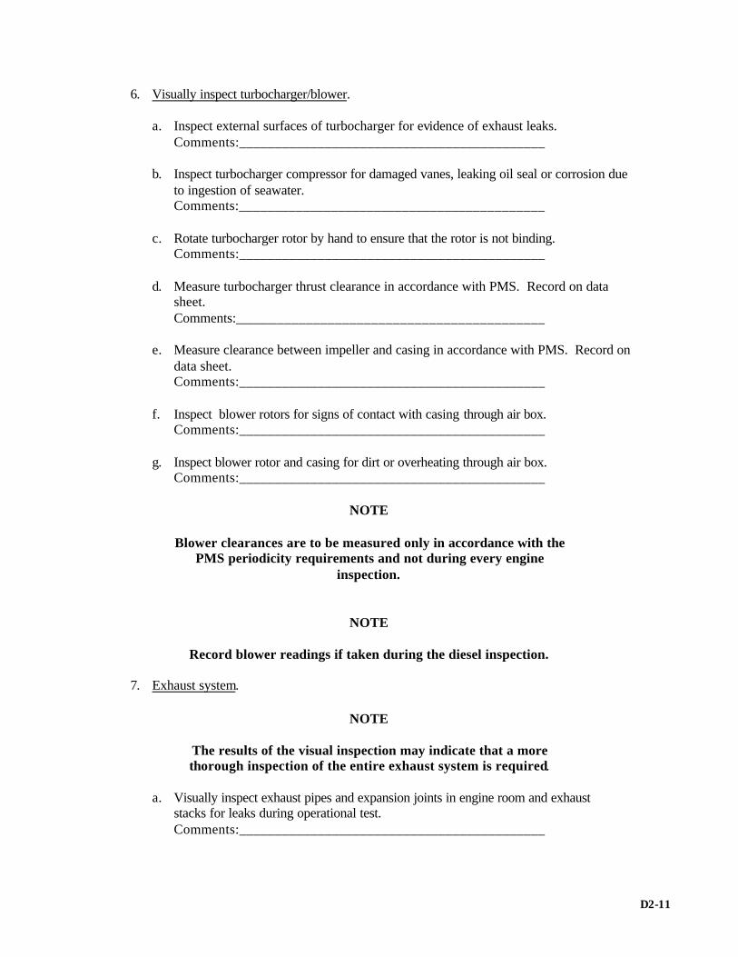
6. Visually inspect turbocharger/blower. a. Inspect external surfaces of turbocharger for evidence of exhaust leaks. Comments:___________________________________________ b. Inspect turbocharger compressor for damaged vanes, leaking oil seal or corrosion due
to ingestion of seawater. Comments:___________________________________________ c. Rotate turbocharger rotor by hand to ensure that the rotor is not binding. Comments:___________________________________________ d. Measure turbocharger thrust clearance in accordance with PMS. Record on data
sheet. Comments:___________________________________________ e. Measure clearance between impeller and casing in accordance with PMS. Record on
data sheet. Comments:___________________________________________ f. Inspect blower rotors for signs of contact with casing through air box. Comments:___________________________________________ g. Inspect blower rotor and casing for dirt or overheating through air box. Comments:___________________________________________
NOTE
Blower clearances are to be measured only in accordance with the PMS periodicity requirements and not during every engine
inspection.
NOTE
Record blower readings if taken during the diesel inspection. 7. Exhaust system.
NOTE
The results of the visual inspection may indicate that a more thorough inspection of the entire exhaust system is required.
a. Visually inspect exhaust pipes and expansion joints in engine room and exhaust
stacks for leaks during operational test. Comments:___________________________________________
D2-11

b. Check engine exhaust muffler for baffle separation and deterioration (if applicable). Comments:___________________________________________ c. Inspect spring hangers for material condition, proper tension, and indications of
movement. Comments:___________________________________________ d. Inspect exhaust stacks for cleanliness, fire or safety hazards. Comments:___________________________________________ e. Check exhaust pipe/silencer drain valves for freedom of movement and clogging. Comments:___________________________________________ f. Inspect exhaust muffler hand hole covers for leaks if applicable. Comments:___________________________________________ 8. Inspect air intake system. Inspect air intake filter elements for cleanliness and proper assembly. Comments:___________________________________________ 9. Flexible hoses, piping, and fittings. a. Inspect flexible hoses for cracks, fraying, rubbing, swelling, and deterioration. Comments:___________________________________________ b. Inspect pipe hangers and flexible hose supports.
NOTE
Fuel and lube oil systems are not permitted to have galvanized fittings.
Comments:___________________________________________ 10. Visually inspect fuel control linkage and governor assembly. a. Check freedom of movement of all racks, linkages, and control shafts. With clevis
pin nuts securely tightened and cotter keys in place, check all linkages for lost motion.
Comments:___________________________________________ b. Use applicable power piston jack to check uniformity of rack settings from idle to full
speed. Comments:___________________________________________ c. Check governor oil level and ensure that no oil leakage around base of governor
exists. Comments:___________________________________________
D2-12
11. Inspect fuel system. a. Check fuel pump flexible coupling spider insert for uneven wear. Check drive shaft oil seal for leakage. Comments:___________________________________________ b. Ensure that filter and strainer shift handles, drain, and installed vent valves operate
correctly. Comments:___________________________________________ c. Randomly check condition of flange shields. Comments:___________________________________________ 12. Inspect lube oil system. a. Check lube oil system and engine attached piping for leakage. Comments:___________________________________________ b. Randomly check condition of flange shields. Comments:___________________________________________ c. Inspect cleanliness of lube oil filter. Pull the lower filter element out, cut it apart, and
inspect it for contamination. Comments:___________________________________________ d. Check for completed PMS on testing of lube oil system relief, bypass, and pressure-
regulating valves. Comments:___________________________________________ e. Inspect cleanliness of turbocharger lube oil filter (if applicable).
NOTE
If turbocharger inlet oil filter is dirty the main lube oil pressure will drop.
Comments:___________________________________________ f. Operate prelube pump and ensure that all rocker arm assemblies have an adequate
flow of lube oil. Comments:___________________________________________ g. Check operation of turbocharger prelubrication system, if installed. Comments:___________________________________________
D2-13

13. Inspect jacket water system. a. Check all jacket water system piping for leakage. Comments:___________________________________________ b. Check for leakage from the telltale hole indicating defective seal on engine attached
jacket water pump. Comments:___________________________________________ c. Inspect jacket water cooler and temperature-regulating valve. Comments:___________________________________________ d. Check for correct level in jacket water expansion tank. Comments:___________________________________________ 14. Inspect crankcase exhauster system. Inspect lube oil separator screen for correct installation and check for excessive oil accumulation. Ensure that the orifice has been installed. Comments:___________________________________________ 15. Inspect seawater system. Check for leakage from the telltale hole indicating defective seal on engine attached seawater pump. Check telltale hole for blockage. Comments:___________________________________________ 16. Inspect clutches and coupling on LST 1179 class MPDE. a. Inspect clutch, shoe, and drum for cleanliness and for excessive wear. Check clutch
shoe torque bars and side plate holes for wear and elongation. b. Check pedestal bearings for oil leakage and ensure that foundation bolts are tight. Comments:___________________________________________ 17. Inspect condition of generator on SSDG and EDG applications. Visually check generator windings to ensure that they are not oil soaked. Comments:___________________________________________ 18. Gages and instruments. Check for proper operation, installation, and calibration during operational test. Comments:___________________________________________
D2-14

19. Safety devices. a. Ensure that label plates for remotely operated safety devices identify the correct
engine and function. Comments:___________________________________________ b. Activate and test all alarms for audibility by using test button. Comments:___________________________________________ c. Test air inlet flapper operation (if applicable). Comments:___________________________________________ d. Remotely operate the emergency trip (inspect for frayed wire and improper
connections). Comments:___________________________________________ e. Check manual trip lever for wear; that is, pins, bushings, and fasteners, for proper
tightness. Comments:___________________________________________
D2-15

FAIRBANKS MORSE ENGINES SECURED-PHASE INSPECTION WORKSHEET
USS__________________________ DATE_________________________ ENGINE NO.___________________ A. SPECIAL TOOLS
NOTE
*Items not applicable to SSBN-726 Class.
NOTE
Inspect a minimum of 25 percent of the following tools.
NOTE
# Can be manufactured as required per applicable technical manual
1. Appropriate size micrometers inside and outside (0 to 11 inch). Comments:____________________________________________ 2. Torque wrenches. a. 8-1/8 (1/2-inch drive) up to 350 ft/lb). Comments:____________________________________________ b. 8-1/8 (3/4-inch drive up to 1000 ft/lb). Comments:____________________________________________ c. 5-1/4 (1/2-inch drive up to 200 ft/lb). Comments:____________________________________________ 3. Crankshaft deflection gage. Comments:____________________________________________ 4. Protractor/crankshaft lead gage. Comments:____________________________________________
D3-1
5. Dial indicator. Comments:____________________________________________ 6. Magnetic base for dial indicator. Comments:____________________________________________ 7. Feeler gages (short). Comments:____________________________________________ 8. Feeler gages (long). Comments:____________________________________________ 9. Hand or strobe tachometer. Comments:____________________________________________ 10. Cylinder pressure gage (Kiene indicator). Comments:____________________________________________ 11. Kiene indicator offset extension (if required). Comments:____________________________________________ 12. Hand tools (PMS-related tools). Comments:____________________________________________ 13. Injector test stand (pop tester). Comments:____________________________________________ 14. Fuel pump stroke and plunger timing gage (8-1/8 only). Comments:____________________________________________ 15. Injection pump discharge valve seat puller (8-1/8 only). Comments:____________________________________________ 16. Vertical drive thrust bearing removal tool. Comments:____________________________________________ 17. Vertical drive bearing nut wrench. Comments:____________________________________________ * 18. Vertical drive wedges (8-1/8 only). Comments:____________________________________________ 19. Cylinder liner adapter tools. Comments:____________________________________________ 20. Journal protector (leather strap). Comments:____________________________________________
D3-2

* 21. Main bearing cap puller. Comments:____________________________________________ 22. Main bearing rollout tools (main and thrust). Comments:____________________________________________ 23. Main bearing light and heavy wrenches. Comments:____________________________________________ 24. Main bearing wrench adapter. Comments:____________________________________________ #* 25. Main bearing journal-lapping tool. Comments:____________________________________________ #* 26. Rod bearing journal-lapping tool. Comments:____________________________________________ 27. Piston ring expander. Comments:____________________________________________ 28. Ring compressor. Comments:____________________________________________ 29. Jacket water test kit. Comments:____________________________________________ 30. Lube oil test kit. Comments:____________________________________________ 31. Piston installation tools for model 5-1/4. a. Two straps (rope). Comments:____________________________________________ b. Two I-bolts. Comments:____________________________________________ c. Two pivot bars. Comments:____________________________________________ d. Crankpin cover. Comments:____________________________________________ 32. Piston installation tools for model 8-1/8. a. Two sliding bars. Comments:____________________________________________
D3-3

b. Two I-bolts. Comments:____________________________________________ c. Two piston winches. Comments:____________________________________________ * 33. Upper crankshaft sprocket puller. Comments:____________________________________________ 34. Air start check valve seating tool. Comments:____________________________________________ 35. Air start control valve seating tool. Comments:____________________________________________ * 36. Lube oil pump shaft coupling puller. Comments:____________________________________________ * 37. Water pump installation sleeve. Comments:____________________________________________ 38. Blower thrust tool. Comments:____________________________________________ * 39. Tensional damper and blower drive gear puller. Comments:____________________________________________ * 40. Blower pinion, timing gear and flange puller. Comments:____________________________________________ * 41. Blower and pump flexible drive hub puller. Comments:____________________________________________ 42. Installation sleeve - blower oil seal (5-1/4 only). Comments:____________________________________________ 43. Thrust bearing lapping tool. Comments:____________________________________________ 44. Fuel pump stroke gage (for engines equipped with gasket less fuel pumps only). Comments:____________________________________________ B. VISUAL INSPECTION (USE PMS cards as reference.)
1. Air box and exhaust belt areas. Isolate the expansion tank, and hydrostatically test the jacket water system according to PMS if any of the following conditions exist; that is,
D3-4

rust, excessive water and chemical makeup, water streaks, obvious external/internal leaks, and NOAP results.
a. Inspect for cleanliness in general (foreign material, broken parts). Comments:____________________________________________ b. Inspect for accumulation of oil. Describe findings. Comments:____________________________________________ c. Inspect condition of ports. Indicate percent reduction, if any. Comments:____________________________________________ d. Check for indication of water, such as rust. Comments:____________________________________________ e. Check condition of rings, pistons, and liners. Inspect for broken rings, blow-by, etc.,
on both sides of the engine. Comments:____________________________________________ f. Inspect visual condition of thermocouples. Indicate thickness of carbon buildup, if
any. Comments:____________________________________________ g. Inspect covers/strong backs for cracks or distortion damage. Comments:____________________________________________ h. Check for missing, broken, or improperly installed lock wire on blower bolts. Comments:____________________________________________ 2. Crankcase: a. Check for missing, broken, or improperly installed cotter pins and lock wire. b. Check internals for discoloration or signs of overheating, foreign material, or broken
parts. Comments:____________________________________________ c. Check for mismatched parts/and cracked welds. Comments:____________________________________________ d. Check all upper and lower main bearing lube oil jumper lines for leakage and lock
wire. Comments:____________________________________________ e. Check connecting rod and main bearing edges for evidence of bearing failure. Comments:____________________________________________
D3-5

NOTE
Aluminum main bearings that have flashed or failed can be detected by using a 0.002-inch feeler gage between the bearing back and the bearing cap at the parting line. If the feeler gage can be inserted it is proof that the bearing has flashed and must be removed. The parting line between the two shells of a flashed bearing will also open so that the 0.002-inch feeler gage can be inserted. Also, the side of the bearing shell should be free of pimples or beads of aluminum, as these indicate a flashed bearing.
Comments:____________________________________________
NOTE
Inserting a 0.002-inch feeler gage in the parting line parallel to the thrust face can check the thrust bearing. If the feeler gage can be inserted more then 7/8 inch at the large thrust flange and 5/8 inch at the small thrust flange it indicates the bearing has failed and must be removed for evaluation.
Comments:____________________________________________
CAUTION
The 0.002-inch feeler gage may slip into the parting line of a perfectly normal 5-1/4 thrust bearing because of a 0.020-inch, plus or minus 0.010-inch, relief machined at the parting line of the thrust flanges.
Comments:____________________________________________
NOTE
A visual check of the rod bearing is usually sufficient. The visual check includes inspecting the bearing shell position. Any sign that the bearing shell has turned in the rod indicates the rod bearing has failed and must be removed.
NOTE
If the initial inspection reveals that a bearing has failed, inspect the associated bearing journal bearing cap and saddle further to determine their damage. Refer to NAVSHIPS 0941-012-7010 supplement to Maintenance and Repair Manual for Fairbanks Morse diesel engines for amplifying instructions.
Comments:____________________________________________
D3-6

f. Check crankshaft lead. Verify pointer (zero degrees). Comments:____________________________________________ g. Check lower crankshaft deflection in accordance with PMS. Record on data sheet. Comments:____________________________________________ h. Check foundation bolts. Check foundations for cracking. Comments:____________________________________________ i. Measure upper and lower crankshaft thrust in accordance with PMS. Record on data
sheet. Comments:____________________________________________ j. Visually inspect all drive gears for signs of overheating, galling, pitting, and unusual
wear patterns. Take backlash readings if necessary.
CAUTION
Do not over-prelube engine.
Comments:____________________________________________ k. Prelube engine and ensure that lube oil flows to all moving parts. Comments:____________________________________________ 3. Vertical drive. a. Check for missing or loose bolts and broken Falk coupling grids (5-1/4 only). Comments:____________________________________________ b. Check load pattern and tooth contact. Comments:____________________________________________ c. Check coupling for broken springs (8-1/8 only). Comments:____________________________________________ d. Check vertical drive riser flange bolts. Comments:____________________________________________ e. Check vertical drive thrust and backlash. Comments:____________________________________________ f. Check the drive hub clamp ringbolt torque. Comments:____________________________________________
D3-7

4. Timing chain. a. Inspect timing chain for proper installation, tension, and excessive wear. Comments:____________________________________________ b. Inspect timing chain master link Comments:____________________________________________ c. Inspect timing chain sprockets. Comments:____________________________________________
NOTE
A new timing chain is 96.250 inches long. The maximum length of an in-service chain is 97. 500 inches long
5. Fuel and governor system. a. Check uniformity of fuel oil pump rack setting (trip fuel control rack).
NOTE
All fuel pumps should now be on zero or less.
Comments:____________________________________________ b. Check freedom of movement of all racks, linkage, roller support, guide rods, and
governor shafts (disconnect governor linkage). Comments:____________________________________________ c. Check governor oil level and check for external oil leaks. Comments:____________________________________________ d. Check fuel pump timing and stoker on No. 1 cylinder (both pumps on double
pumpers) and run a random check on one additional pump(s). Comments:____________________________________________ e. Ensure that fuel control rod stop bolt has been lock wired and/or locknut installed. Comments:____________________________________________
f. Using a magnet check to ensure fuel oil crossover lines are steel, copper (no Bundyweld piping is allowed) and rubber hoses are not authorized. If crossover piping must be changed use, pipe assembly Fairbanks-Morse Part Numbers 16 608 646 or crossover assembly Part Number 16 205 456.
Comments:_____________________________________________
D3-8
The following is a Safety Item (Mandatory Inspection)
Note: The following inspection is applicable only to those engines with two (2) injection pumps per cylinder.
f. Remove the front cover’s center inspection plate, visual inspect the right-hand fuel
control rod insert (viewed from the drive end of engine) for sufficient interference fit. If there is any evidence of the insert pull-out (0.050” or more the fuel control rod with the insert shall be replaced. Refer to Figure 1.
With the front cover removed, the following shall be accomplished:
1. With the shutdown cocked and the control arm against the rack stop, adjust the adjusting screw to a clearance of 0.010” to 0.030”
between the screw and shutdown lever button. Refer to Figure 1. 2. Remove and discard any 3/8” thick washers behind the shutdown
spring.
CAUTION If the washers are removed, the rack must be inspected at shutdown to assure
injection pumps on both sides are at “ 0 “or less. 3. With the shutdown released, adjust the clearance between the stop
nuts on the shutdown stem and the reset lever to 0.060”.
D3-9

Figure 1
Comments:_____________________________________________________ 6. Flexible hoses, piping and fittings. a. Inspect flexible hoses for cracks, fraying, rubbing, swelling, and deterioration.
NOTE
Galvanized fittings are not permitted in the lube oil or fuel oil systems. Comments:___________________________________________ b. Inspect all pipe hangers and flexible hose supports for correct installation. Comments:___________________________________________
D3-10

7. Camshaft. a. Inspect camshaft for pitting, galling, discoloration, and excessive wear. Comments:___________________________________________ b. Check camshaft-bearing edges for evidence of bearing failure. Comments:___________________________________________ c. Check air start distributor timing for No. 1 cylinder. Comments:___________________________________________ 8. Jacket and raw water pumps and piping. a. During operational test, inspect pumps and piping for leakage. Comments:___________________________________________ b. Check locating dowels in end plates. Comments:___________________________________________
9. Engine fuel oil and generator bearing scavenging lube oil pumps during operational test. a. Inspect lube oil pumps. Comments:___________________________________________ b. Inspect fuel oil pump. Comments:___________________________________________ 10. Scavenging air blower. a. Inspect blower for metal-to-metal contact and oil in blower cavity. Comments:___________________________________________ b. Check condition of blower rotors and housing. Comments:___________________________________________ c. Check condition of gears and bearings, and spacers. Comments:___________________________________________ d. Check oil separator and vacuum breaker for contamination and deterioration. Comments:___________________________________________ e. Take blower reading required by data sheet paragraphs 4a through d.
NOTE
Take and record blower reading if visual inspection warrants it. Comments:___________________________________________
D3-11

11. Air intake system. Inspect filter elements/screens for cleanliness, proper installation, and missing installation clips. Comments:___________________________________________ 12. Exhaust system.
NOTE
The results of the visual inspection may indicate a more thorough inspection of the entire exhaust system is required.
a. Visually inspect exhaust pipes and expansion joints in engine room and exhaust stacks
for leaks during operational test. Comments:___________________________________________ b. Check engine exhaust muffler for baffle separation and deterioration (if applicable). Comments:___________________________________________ c. Inspect spring hangers for material condition, proper tension, and indications of
movement. Comments:___________________________________________ d. Inspect exhaust stacks for cleanliness, fire or safety hazards. Comments:___________________________________________ e. Check exhaust pipe/silencer drain valves for freedom of movement and clogging. Comments:___________________________________________ f. Inspect exhaust muffler hand hole covers for leaks if applicable. Comments:___________________________________________ 13. Lube oil system. a. Check for any leakage of oil from pipe connections and flanges (to be observed during
operational test.) Comments:___________________________________________ b. Check for signs of overheating of lube oil pump housing. Comments:___________________________________________ c. Remove and open one lube oil filter element per engine (lower one if installed) and
inspect for types of contamination. Comments:___________________________________________
D3-12

d. Inspect filter elements for correct type and installation.
NOTE
No sock-type filters. Comments:___________________________________________ e. Ensure that valves in the lube oil system that could obstruct the flow of oil to the
engine have been locked fully open with proper locking devices. Comments:___________________________________________ f. Check for completed PMS on testing of lube oil system relief, bypass, and pressure-
regulating valves. Comments:___________________________________________ g. Ensure that all sump drain valves are locked closed and capped. Comments:___________________________________________ 14. Fuel oil filters and strainers. a. Ensure that shifting lever operated properly. Comments:___________________________________________ b. Check for completed PMS on testing of fuel oil system relief, bypass, and pressure-
regulating valves. Comments:___________________________________________ 15. Heat exchangers and temperature-regulating valves. a. Inspect heat exchangers for external leaks. Comments:___________________________________________ b. Inspect temperature-regulating valves for proper operation and external leaks. Comments:___________________________________________ c. Check level in jacket water expansion tank. Comments:___________________________________________ 16. Gages and instruments. Check for proper operation, installation, and calibration during operational test. Comments:___________________________________________
D3-13

17. Safety devices. a. Ensure that all label plates for remotely operated safety devices identify the correct
engine and function. Comments:___________________________________________ b. Activate and test all alarms for audibility by using test button. Comments:___________________________________________ c. Test air inlet flapper operation (if applicable). Comments:___________________________________________ d. Remotely operate the emergency trip (inspect for frayed wire and improper
connections.) Comments:___________________________________________ e. Check manual trip lever for wear; that is, pins, bushings, and fasteners, for proper
tightness. Comments:___________________________________________ 18. Generator (if applicable). a. Inspect for lube oil and seawater leaks. Comments:___________________________________________ b. Check generator internals for signs of lube oil contamination. Comments:___________________________________________ c. Measure rotor shaft drop reading at pedestal bearing against stamped reading in
accordance with PMS. Comments:___________________________________________ d. Check pedestal bearing for grounding in accordance with current PMS, 900-RPM generator sets only. Comments:___________________________________________
D3-14

COLT-PIELSTICK SECURED-PHASE INSPECTION WORKSHEET
USS ________________________ DATE_______________________ ENGINE NO._________________ A. SPECIAL TOOLS:
NOTE
Inspect a minimum of 25 percent of the following tools. 1. Tools for tightening main bearing side screws. Comments:___________________________________________ 2. Hydraulic jack for tightening main bearing saddle studs. Comments:___________________________________________ 3. Swing rod (main bearing saddle stud nut). Comments:___________________________________________ 4. Lower main bearing shell removal tools. Comments:___________________________________________ 5. Tool to dismantle main bearing cap. Comments:___________________________________________ 6. Tool for hydraulic tightening of main bearing. Comments:___________________________________________ 7. Special socket (oil plug main bearing cap). Comments:___________________________________________ 8. Tool for tightening and dismantling connecting rod stud. Comments:___________________________________________ 9. Tool to check connecting rod stud elongation. Comments:___________________________________________ 10. Connecting rod cap loader assembly. Comments:___________________________________________ 11. Support tool for connecting rod and piston assembly. Comments:___________________________________________
D4-1

12. Tools for removing connecting rod. Comments:___________________________________________ 13. Piston and connecting rod lifter. Comments:___________________________________________ 14. Piston pin extractor. Comments:___________________________________________ 15. Piston ring compressor. Comments:___________________________________________ 16. Piston ring gap measuring tool. Comments:___________________________________________ 17. Piston ring expander. Comments:___________________________________________ 18. Piston skirt protection collar. Comments:___________________________________________ 19. Lifter for cylinder liner and water jacket. Comments:___________________________________________ 20. Tool for disassembling cylinder liner from water jacket. Comments:___________________________________________ 21. Spacer assembly (liner removal). Comments:___________________________________________ 22. Cylinder liner stud thread protector. Comments:___________________________________________ 23. Lifter for cylinder head assembly. Comments:___________________________________________ 24. Cylinder head and liner lapping too. Comments:___________________________________________ 25. Exhaust valve seat decarboning tool. Comments:___________________________________________ 26. Cylinder head hydraulic pressure test tool. Comments:___________________________________________ 27. Fitting and dismantling valve springs tool. Comments:___________________________________________
D4-2
28. Jackscrew for exhaust valve removal. Comments:___________________________________________ 29. Inlet valve seat cutter assembly. Comments:___________________________________________ 30. Support assembly tool for dismantling exhaust valves. Comments:___________________________________________ 31. Tool for cleaning injection nozzle tip. Comments:___________________________________________ 32. Injection nozzle gasket removal tool. Comments:___________________________________________ 33. Holder for nozzle tip removal and assembly tool. Comments:___________________________________________ 34. Injection nozzle puller tool. Comments:___________________________________________ 35. Test stand assembly for PC2.5 injection nozzle and cylinder head safety valve (pop tester). Comments:___________________________________________ 36. Tooling, lapping the injector-seating surface. Comments:___________________________________________ 37. Nozzle tip gasket installation tool. Comments:___________________________________________ 38. Air start and safety valve extractor assembly. Comments:___________________________________________ 39. Fixture assembly for testing cylinder head safety valve. Comments:___________________________________________ 40. Support for dial indicator assembly for setting valve lash. Comments:___________________________________________ 41. Split cam screw drive extension. Comments:___________________________________________ 42. Air-start distributor rotor puller. Comments:___________________________________________ 43. Tooling for manual control of fuel pump assembly. Comments:___________________________________________
D4-3

44. Special wrench, Allen 10 mm. Comments:___________________________________________ 45. Gear-lifting tool. Comments:___________________________________________ 46. Nut for unclamping tapered sleeve or camshaft drive gear. Comments:___________________________________________ 47. Thrust bearing removal tool Comments:___________________________________________ 48. Striking wrench 55 mm, heavy duty. Comments:___________________________________________ 49. Crankshaft distortion gage. Comments:___________________________________________ 50. Tools for measuring clearance at crankshaft journal. Comments:___________________________________________ 51. Dial indicator assembly for crankshaft clearance. Comments:___________________________________________ 52. Counterweight stud tool assembly. Comments:___________________________________________ 53. Impact socket, 2-inch 8-point, with sliding T-handle, 1-inch drive. Comments:___________________________________________ 54. Counterweight lifting tools. Comments:___________________________________________ 55. Roll pin removal and installation tool. Comments:___________________________________________ 56. Grease gun, 14 oz, with hose and two couplers. Comments:___________________________________________ 57. Bellow handling tool (exhaust manifold). Comments:___________________________________________ 58. Long flat chisel 15-1/2 to 18 inches long, 7/8-inch across flats. Comments:___________________________________________ 59. Wrench, 7/8-inch, single end flare nut, 12-point. Comments:___________________________________________
D4-4

60. Wrench 9/16-inch, single end flare nut, 12-point. Comments:___________________________________________ 61. Warren water pump impeller puller. Comments:___________________________________________ 62. Wrench 60 mm, super heavy duty slugging, 12-point. Comments:___________________________________________ 63. Hydraulic hand pump. Comments:___________________________________________ 64. Kiene pressure indicator. Comments:___________________________________________ 65. Eyebolt. Comments:___________________________________________ 66. Turbocharger tools. Comments:___________________________________________ 67. Wrench-open-end double – 6-7, 8-9, 10-11, 12-13, 14-15, 16-17, 19-22, 24-27, 30-32 mm Comments:___________________________________________ 68. Wrench-open-end double 5/16-inch 1-inch (25 mm). Comments:___________________________________________ 69. Wrench-open-end double 1-1/2 inch (38 mm) - 1-5/8 inch. Comments:___________________________________________ 70. Wrench-open-end double 2-3/16 inch (71 mm) - 2-5/8 inch. Comments:___________________________________________ 71. Wrench-open-end single 3, 3-3/8, 3-3/4, 4-1/8 inch; 42, 58 60 (2-3/8 inch), 82 mm. Comments:___________________________________________ 72. Ratchet, 3/4-inch drive with 35-inch handle. Comments:___________________________________________ 73. Extension, 1-inch drive, 7-1/8 inch-7-1/2 inch. Comments:___________________________________________ 74. Wrench-Allen 6, 8, 10, 12, 14, 17, 24 mm. Comments:___________________________________________ 75. Screwdriver (small) standard blade 0.046 inch. Comments:___________________________________________
D4-5

76. Screwdriver (large) standard blade 0.075 inch. Comments:___________________________________________ 77. Punch, pin 1/8-inch dia. Comments:___________________________________________ 78. Punch, pin 1/4-inch dia. Comments:___________________________________________ 79. Plier, snap-ring (int/ext) 2-1/16 x 3-11/32 inch. Comments:___________________________________________ 80. Plier, snap-ring (int/ext) 3/16-inch-dia. to 1-3/8-inch-dia. rings. Comments:___________________________________________ 81. Torque wrench, 1/2-inch drive, and 175-lb/ft capacity. Comments:___________________________________________ 82. Wrench-torque multiplier (4:1) 3/4-inch sq female dr, 1-inch sq male drive. Comments:___________________________________________ 83. Tool for tightening cylinder head nuts (socket impact 2-1/2 inch with 1-1/2 drive. Comments:___________________________________________ 84. Torque wrench, 3/4-inch drive, and 600-lb/ft capacity. Comments:___________________________________________ 85. Socket, 29 mm 1/2-inch drive, 12 pt. Comments:___________________________________________ 86. Socket, 26 mm 1/2-inch drive, 12 pt. Comments:___________________________________________ 87. Socket, impact 30 mm 1-inch drive, 6 pt. Comments:___________________________________________ 88. Socket, impact 28 mm, 1-inch drive, 6 pt. Comments:___________________________________________ 89. Adapter, Dr 1/2-inch male to 3/4-inch female. Comments:___________________________________________ 90. Exhaust valve bushing removal tool. Comments:___________________________________________ 91. Socket, 36 mm 3/4-inch drive with modified OD. Comments:___________________________________________
D4-6

92. Torque adapter, 26 mm 1/2-inch drive. Comments:___________________________________________ 93. Metric Allen wrench, sizes 2 mm-19 mm. Comments:___________________________________________ 94. Metric socket set. Comments:___________________________________________ 95. Combination open-end wrench set, sizes 6 mm-19 mm. Comments:___________________________________________ 96. Combination wrench - 20, 21, 23, 26 mm. Comments:___________________________________________ 97. Large snap ring pliers. Comments:___________________________________________ 98. Rocker-arm spacer. Comments:___________________________________________ 99. Roller lock assembly. Comments:___________________________________________ 100. Roller lock block. Comments:___________________________________________ 101. Tool, thrust bearing spacer. Comments:___________________________________________ 102. Socket, 2-1/2-inch x 1-inch drive. Comments:___________________________________________ 103. Borescope. Comments:___________________________________________ 104. Tool, overspeed trip. Comments:___________________________________________ 105. Too, bypass/waste gate valve spring compressor. Comments:___________________________________________ 106. Wrench, open end, 2-5/8 inch. Comments:___________________________________________ 107. Wrench, open end, 46 mm. Comments:___________________________________________
D4-7

B. VISUAL INSPECTION 1. Sub base, crankcase, and block.
a. Check for missing or lose bolts, block to base. Inspect chocks for shifting and cracked welds.
Comments:___________________________________________
b. Remove crankcase inspection covers and check internals for discoloration or signs of overheating. Check crankcase for foreign particles and indications of jacket water leakage. Spot check for mismatched connecting rod and connecting rod caps. Check for serial number and orientation.
Comments:___________________________________________ c. Inspect all connecting-rod bolts for proper installation and lock wire (PMS). Comments:___________________________________________
d. Inspect lock washer, securing cap screws, and lock plates on all main bearing caps for proper installation (PMS).
Comments:___________________________________________ e. Check connecting rod and main bearing edges for evidence of bearing failure (PMS). Comments:___________________________________________
f. Check visible areas of all liners for scoring, scuffing, and abrasion. Check for indications of jacket water leakage. Some polishing will exist and is considered normal for this engine (PMS).
CAUTION
Use extreme care, as engine must be barred over. Comments:___________________________________________ g. Check all internal lube oil jumpers for looseness (PMS). Comments:___________________________________________
h. Inspect crankcase inspection covers and cover relief valves for loose or missing gaskets and fasteners.
Comments:___________________________________________
i. Remove inspection plates on both sides of engine and inspect crankshaft gear for broken teeth, unusual wear pattern, excessive wear, and improper lubrication.
Comments:___________________________________________
D4-8

CAUTION
Use extreme care, as engine must be barred over. Comments:___________________________________________
j. Inspect all auxiliary drive gears, including camshaft drive, for broken teeth, unusual wear pattern, or excessive wear.
CAUTION
Use extreme care, as engine must be barred over.
Comments:___________________________________________ k. Inspect Gieslinger coupling for signs of oil leakage (PMS). Comments:___________________________________________ l. Measure crankshaft thrust according to PMS. Comments:___________________________________________
m. Take a complete set of crankshaft deflection readings and bearing presses. (If readings taken within three months before engine inspection are within
specification, the data may be used to satisfy the requirements of this step.) Document measurements on record sheet. Comments:___________________________________________ n. Check for adequate oil flow. See paragraph 2g. Comments:___________________________________________ 2. Camshaft, top deck and valve gear.
a. Remove all camshaft covers and inspect camshaft lobes for excessive wear, galling, flat spots, or discoloration (PMS). Inspect fuel cams for excessive pitting and sliding contact surface damage. Relatively small pits, widely dispersed over the fuel cam and roller contact surface are acceptable for continued use. Moderate shallow pitting of single areas not exceeding 1/4 inch in diameter are acceptable for continued use. Pitted cams shall be re-inspected at six moth intervals to determine if pitting has progressed or if surface damage has increased. Cams with severely spalled surfaces or deep pits shall be replaced. Questionable cam surface damage shall be referred to NSWCCD-SSES for replacement criteria.
Comments:___________________________________________
D4-9

b. Check for any evidence of fuel or water leakage around the outside of the cylinder head area and inside the valve cover.
Comments:___________________________________________
c. Inspect camshaft thrust bearing cover and thrust bearing housing for looseness. If a loose assembly is found, remove cover and inspect camshaft castle nut and cotter pin for looseness. Measure camshaft thrust at 16,000 engine hours or as situation requires.
Comments:___________________________________________ d. Inspect camshaft supplemental support bearing cap screw IAW NAVSEA Technical
Manual S9233-A8-MMO-010 Change G 28 July 1995 and NAVSURFWARCEN SHIPSYSENGSTA PHILADELPHIA PA MESSAGE DTG 172020Z JUN 02. This inspection is mandatory every 500 hours of engine operation for all Engines that have not been repaired.
e. Inspect for broken springs on valves (PMS). Comments:___________________________________________ f. Check for any excessive looseness in the rocker arm assemblies (PMS). Comments:___________________________________________ g. Check and record valve clearances on at least two cylinders on each bank (PMS). Comments:___________________________________________
h. Ensure that sump tank is filled with oil to normal non-operating level and heated to 100°F minimum/140°F maximum. Operate main lube oil standby/prelube pump. Check for adequate oil circulation from all main, connecting- rod, and camshaft bearings, pistons, injection pump rollers, and gears.
Comments:___________________________________________ 3. Turbocharger. a. Visually inspect oil level and condition of oil through sight glasses. Comments:___________________________________________ b. Inspect external surface of the turbocharger for evidence of exhaust leaks. Comments:___________________________________________ c. Ensure that turbocharger surge control system operates properly. Statically test
bypass and waste gate valves (PMS). Comments:___________________________________________
D4-10

4. Exhaust system.
NOTE
The results of the visual inspection may indicate that a more thorough inspection of the entire exhaust system is required.
a. Visually inspect exhaust pipes and expansion joints in engine room and exhaust
stacks for leaks during operational test. Comments:___________________________________________ b. Check engine exhaust muffler for baffle separation and deterioration (if applicable). Comments:___________________________________________ c. Inspect spring hangers for material condition, proper tension, and indications of
movement. Comments:___________________________________________ d. Inspect exhaust stacks for cleanliness, fire or safety hazards. Comments:___________________________________________ e. Check exhaust pipe/silencer drain valves for freedom of movement and clogging. Comments:___________________________________________ f. Inspect exhaust muffler hand hole covers for leaks if applicable. Comments:___________________________________________ 5. Intake System. a. Remove free end cover of each intake manifold and inspect for lube oil and debris. Comments:___________________________________________ b. Ensure that all intake filter elements are installed and firmly seated in the housing.
Inspect elements for cleanliness and deterioration. Comments:___________________________________________ c. Inspect air ducting within the machinery space for cracks, missing sections, and loose
or missing fasteners. Comments:___________________________________________ d. Ensure that blow-in door operates properly and closes completely when reset. Comments:___________________________________________
The following is a Safety Item (Mandatory Inspection)
e. Inspect MPDE Combustion Air Shutoff Valve Time Delay:
1. Ship's air supply pressure regulator to the Valve shall be set at 100 PSI IAW MPDE T/M NAVSEA S9233-A8-MMO-010, Fig. 3-3.
D4-11

2. Valve shall close within 25 +10 / -5 seconds IAW MPDE T/M Fig. 3-3 and (revised) MRC 6WMJ N. (TFBR LSD 48 Ser 0056-02). 3. Corrective action for Valve closure not IAW 25 +10 / -5 seconds time delay requires Kidde Time Delay Cylinder modification by OEM/FMED to comply with new FMED Drawing P12619832. Comments:______________________________________________
f. Check the forward and aft space bars supporting the intercoolers. Refer to figure
F7-52 in the NAVSEA Technical Manual S9233-A8-MMO-010. Ensure that the space bars and locknuts at each end cannot be rotated by hand. If the bar is not tight or turns freely or if locknuts are loose, contact NAVSEA-Philadelphia, Code 9325 for direction.
Comments:________________________________________________ 6. Flexible hoses. a. Inspect flexible hose for cracks, fraying, rubbing, swelling, and deterioration. Comments:___________________________________________ 7. Fuel control linkage and governor assembly. a. Check and record injector fuel pump timing on at least two cylinders on each bank. Comments:___________________________________________ b. Check governor oil level and oil leakage around base of governor. Visually inspect
oil condition through sight glass. Comments:___________________________________________ c. Check all racks, linkages, and control shafts for loose or missing fasteners. Comments:___________________________________________ d. Check freedom of movement of all racks, linkages, and control shafts (use the
manual stop lever to move racks through full range of travel). Comments:___________________________________________
e. Check uniformity of rack settings (use manual stop lever to move rack to full load position). Ensure that rack stop has been set at 39 mm. Ensure that lead seal on rack stop adjusting screw is intact.
Comments:___________________________________________
f. Ensure that fuel rack boost is 15 mm plus or minus 3 mm (PMS). Comments:___________________________________________
The following is a Safety Item (Mandatory Inspection) D4-12

g. The fuel control rod linkage consists of the regulating bar and the connecting tube, which are held together by roll pins. Inspect the roll pins for proper orientation and wear IAW figure 1. Roll pins that have incorrect orientation is incorrect or are worn shall be replaced.
8. Fuel system. a. Operate fuel oil standby pump and inspect fuel oil jumper liner and connections for
leakage. Check flange shields for fuel soaking, indicating flange connection leakage (perform this inspection after injector fuel pump timing checks).
Comments:___________________________________________ b. Inspect fuel oil pump telltale drain for signs of leakage. Comments:___________________________________________ c. Check operation of hand priming pump. (Ensure that standby pump is off.) Comments:___________________________________________ d. Ensure that fuel filter shift handle operates correctly. Comments:___________________________________________
D4-13

e. Inspect filter vent and drain valves for correct operation. Comments:___________________________________________ f. Inspect one filter element for excessive contaminants and correct installation (PMS). Comments:___________________________________________ g. Using a feeler gauges, check the clearances between the upper flange and the fuel
injection pump body in five places, the nominal clearance is 0.065 to 0.075. The clearance shall be within 0.003 of the nominal clearance. All pumps must be checked.
9. Main and rocker lube oil systems. a. Check operation of hand priming pump (ensure that standby pump is off). Comments:___________________________________________ b. Drain rocker lube oil reservoir. Inspect one rocker lube oil strainer basket for
excessive contaminants and correct installation (PMS). Ensure that reservoir sight glass indicates that reservoir refills when main lube oil standby pump is operated.
Comments:___________________________________________ c. Operate main lube oil standby/prelube pump and inspect lube oil manifold for
leakage. Inspect lube oil cooler for external leaks. Check flange shields for oil soaking, indicating leakage of oil from flange connections.
Comments:___________________________________________
d. Operate the rocker lube oil standby pump and ensure that all rocker arm assemblies are getting lube oil. Check piping system for leakage.
Comments:___________________________________________ e. Inspect main lube oil strainer interlock and shift mechanism for loose and missing
fasteners and correct operation.
CAUTION
Lube oil strainer interlock must be pressurized on both sides before shifting, or interlock will be damaged.
f. Inspect main lube oil strainer vent and drain valves for correct operation. Comments:___________________________________________ g. Inspect one main lube oil strainer basket for excessive contamination and correct
installation. Comments:___________________________________________
D4-14

h. Inspect main lube oil filter vent and drain valves for correct operation. Comments:___________________________________________
i. Inspect one main lube oil filter element for excessive contaminants and correct installation (PMS).
j. Check lube oil sampling valves for hand wheels and caps. Record specific location
of sampling valve in system (examples: upstream of filter, at standby pump casing vent, etc.).
Comments:___________________________________________
k. Inspect each MPDE attached lube oil pump for loose thrust bearing assembly lock washers and locknuts, and loose or damaged roller bearings. Isolate and tag-out the affected portion of the lube oil system. Remove pump relief valve. Visually inspect the condition of the upper and lower pump shaft drive end roller bearings visible through the forward relief valve port in the pump body. The outer races of the roller bearings should be flushed with the face of the front head housing and should be secured in the housing by the socket heat capscrews, washers and lock wire. Ensure cap screw lock wire is in place. The inner races of the roller bearings should be even with the outer races and be in contact with the shaft shoulder on both the upper and lower shafts. If a gap exists between the shaft shoulder and the aft end of the inner roller bearing race, the bearing is migrating off the pump shaft and shall be repaired/replaced. Remove nuts from studs and remove only the rear head cover. Clean gasket from rear head. Visually inspect the toothed lock washer for damage to locking tabs, and ensure that one lock tab is completely and properly secured in a locknut slot. Check that locknut is tight against lock washer No. 43 and thrust bearing spacer sleeve. Check for evidence that locktite has been applied to the locknut.
CAUTION
Replacement gasket for rear head must be made from .007-inch thick material. Use of any other gasket material will affect the pump thrust bearing clearance.
10. Jacket water system. a. Check for correct level of jacket water in expansion tank. Comments:___________________________________________
b. Operate the jacket water standby pump. Check for leakage from the attached pump telltale hole (leakage indicates defective mechanical seal).
Comments:___________________________________________ c. Ensure that the constant vent has been installed on the attached pump case. Comments:___________________________________________
D4-15

d. Ensure that attached pump suction and discharge local gages have been installed and calibrated.
Comments:___________________________________________ e. Inspect jacket water cooler and injector cooler for external leaks. Comments:___________________________________________ f. Inspect temperature-regulating valve manual overrides for freedom of movement
(jacket water and injector cooler). Ensure that regulating valves have been reset in automatic mode.
Comments:___________________________________________ 11. Jacket water keepwarm system.
a. Operate the jacket water keep warm pump. Check pump, piping, heater, and heater relief valve for leaks.
Comments:___________________________________________ 12. Seawater system.
a. Ensure that seawater system has been pressurized. Check for leakage form the attached pump telltale hole (leakage indicates defective mechanical seal).
Comments:___________________________________________ b. Ensure that attached pump has a vent valve on the pump case and that it operated
correctly. Comments:___________________________________________ c. Ensure that attached pump suction and discharge local gages have been installed and
calibrated. Comments:___________________________________________ d. Manually cycle the Leslie three-way control valve (shut off the air supply and bleed
pressure from diaphragm). Check for free movement through full valve stroke. Check material condition of valve, stem packing, etc. Reconnect air supply and ensure that air pressure regulators to Leslie temperature pilot and volume booster have been set to correct pressure.
Comments:___________________________________________ e. Manually cycle the emergency cooling water valves (shut off the air supply and bleed
pressure from diaphragm). Check for free movement through full valve stroke. Reconnect air supply.
Comments:___________________________________________ f. Open both sea chest strainer baskets. Check for excessive blockage and marine
growth. Comments:___________________________________________
D4-16

g. Measure seawater pump drive thrust and wear ring diametric clearance (PMS). Comments:___________________________________________ 13. Crankcase vacuum system. a. Ensure that lube oil separator and piping loop seals have been filled to the correct
level with engine lube oil. Comments:___________________________________________ b. Inspect vacuum fans for oil leaks. Comments:___________________________________________ 14. Air start system. a. Check oil level in air start oilier. Comments:___________________________________________
b. Open and inspect air start filter for excessive contaminants. Replace filter. Comments:___________________________________________ 15. Safety checks.
a. Operate all remote emergency trips. Inspect for loose or missing fasteners on operating mechanisms. Ensure proper operation of pneumatic/hydraulic fuel rack shutdown, clutch disengage valve, intake air emergency shutdown valve (PMS).
Comments:___________________________________________ b. Perform static check of overspeed trip mechanism. Ensure that rack returns to no-
fuel position (PMS). Comments:___________________________________________ c. Test barring device interlock (PMS). Comments:___________________________________________ d. Randomly check condition of flange shields. Comments:___________________________________________ e. Ensure that emergency fuel shutoff valves operate properly (local and remote). Comments:___________________________________________ 16. Gages and instruments. Check for proper operation, installation and calibration during operational test. Comments:___________________________________________
D4-17

DDA 16V 149 DIESEL ENGINES SECURED PHASE INSPECTION WORKSHEET
USS:__________________________________________ DATE_________________________________________ ENGINE NO.___________________________________ A. SPECIAL TOOLS
NOTE
Inspect a minimum of 25 percent of the following tools.
1. Appropriate size micrometers inside and outside (1 to 7 inches). Comments:___________________________________________________________
2. Torque wrenches (inch and ft-lb) (up to 3/4 inch drive).
Comments:___________________________________________________________ 3. Dial indicator. Comments:___________________________________________________________ 4. Magnetic base for dial indicator. Comments:___________________________________________________________ 5. Feeler gages (long). Comments:___________________________________________________________ 6. Feeler gages (short). Comments:___________________________________________________________ 7. Hand or strobe tachometer. Comments:___________________________________________________________ 8. Hand tools. Comments:___________________________________________________________ 9. Piston ring compressor. Comments:___________________________________________________________ 10. Piston profile gage (J-25397). Comments:___________________________________________________________ 11. Piston ring expander. Comments:___________________________________________________________
D5-1
12. Cylinder liner installing tool. Comments:___________________________________________________________
13. Cylinder liner removing tool. Comments:___________________________________________________________
14. Engine barring tool. Comments:___________________________________________________________
15. Injector timing tool (2.205). Comments:___________________________________________________________
16. Governor linkage setting gage. Comments:___________________________________________________________
17. Turbocharger radial reading adapters for dial indicator. Comments:___________________________________________________________
18. Manometer (crankcase pressure). Comments:___________________________________________________________
19. Comparator (Detroit switches). Comments:___________________________________________________________
20. Jacket water test kit. Comments:___________________________________________________________
21. Lube oil test kit. Comments:___________________________________________________________
22. Cylinder head removal tool. Comments:___________________________________________________________
23. Fuel injector torque wrench. Comments:___________________________________________________________
24. Hand-held gage 0-100 psi. Comments:___________________________________________________________
25. Hand-held pyrometer. Comments:___________________________________________________________
26. F10 priming pump. Comments:___________________________________________________________
D5-2

B. VISUAL INSPECTION 1. Air inlet shutdown devices. a. Check condition and operation of safety switches. Comments:____________________________________________ b. Check condition of flappers. Visually check flapper resilient mount for through-bolt
configuration and condition. Comments:____________________________________________ c. Check condition and operation of latch devices and flapper linkages. Comments:____________________________________________ d. Check condition and operation of remote cables. Comments:____________________________________________ e. Ensure that all remotely operated safety device label plates have been properly
installed. Comments:____________________________________________ 2. Blowers. a. Check blower lobes for presence of wear and oil. Comments:____________________________________________ b. Check readings (see tolerance measurements). Comments:____________________________________________ 3. Turbochargers and air filters. a. Visually inspect filters for cleanliness (also check performance). Comments:____________________________________________ b. Inspect turbocharger compressors for damaged vanes or leaking oil seal. Comments:____________________________________________ c. Inspect for evidence of exhaust leaks. Comments:____________________________________________ d. Inspect turbo adapters, intercoolers, and flange connections for evidence of oil,
contamination, and water leaks (also check performance). Comments:____________________________________________ e. Measure turbocharger axial movement. (Refer to Tolerance Measurement Data
Sheet, Appendix G5). Comments:____________________________________________
D5-3
f. Check turbocharger-rotating assembly for freedom of movement without binding. Comments:____________________________________________
NOTE
Overloading the turbochargers can damage them. Exhaust system deficiencies (i.e. hangers set improperly) can cause turbocharger distress.
g. Check that pop up gages air filters are of the correct one, installed, and function.
NOTE
Note the current pop-up indicators have marks for recording readings.
Comments:____________________________________________ h. Inspect air ducting from filters to blowers for cracks, missing fasteners, and air leaks
(also check operation). Comments:____________________________________________ 4. Upper running assemblies. a. Thrust camshafts in order to check camshafts and thrust assemblies for excessive
wear and proper lubrication. Refer to tolerance Measurement Data Sheet, Appendix G5.
Comments:____________________________________________
NOTE
Some spalling of cam follower rollers may be normal. If spalled rollers are not gouged or chipped they need not be replaced.
Comments:____________________________________________ b. Check exhaust valves and springs for proper installation. Check spring retainers and
valve locks for proper seating. Comments:____________________________________________ c. Inspect injectors and racks (state rack and injector number). Comments:____________________________________________
D5-4

d. Check to ensure that fuel injector screw plugs are fully seated and engaged into the body of the injector.
NOTE
Fuel injector control rack must have 100 percent unrestricted travel. The control rack must not contact the body screw plug. Fuel injector control racks must not be machined to attain specified fuel output.
Comments:____________________________________________ e. Check jumper lines for proper installation and for leaks and torque. Use special
torque wrench only. Comments:____________________________________________ f. Check injector control tubes for proper installation and freedom of movement Comments:____________________________________________ g. Check fuel jumper line support clips for proper installation/torque. Comments:____________________________________________ h. Spot check (2 per side) valve clearances and fuel injector timing. (Refer to previous
operational logs to determine past performance and that variations of exhaust temperatures from cylinder to cylinder and bank-to-bank are/are not within specification.)
Comments:____________________________________________ 5. Air box. a. Check air box for accumulation of oil and contaminants. Comments:____________________________________________ 6. Cylinder liners. a. Inspect cylinders for scoring, galling, cross hatching, excessive wear.
NOTE
Be aware of class advisory concerning defective piston pin bushings (ISE Advisory 018-88). Do not use bushings marked with the date 9-87 or 1-88 for any reason. If slipper bushing distress has occurred, the piston skirt will show severe scuffing, discoloration from its normal silver-gray to black or dark blue, and tin melt (mottling of the surface texture) will be apparent.
Comments:____________________________________________
D5-5

7. Pistons and piston rings. a. Inspect pistons for excessive wear, galling, and scoring. Comments:____________________________________________ b. Inspect rings for scuffing, fracture, and abnormal sticking and carbon deposits. Comments:____________________________________________ 8. Exhaust manifolds. Inspect exhaust manifold internally for contaminants. Comments:____________________________________________ 9. Main and connecting rod bearings, thrust collars. a. Inspect main bearings and connecting rod bearings for proper installation. Comments:____________________________________________ b. Inspect bearing connecting rod bolts and nuts for correct installation. Comments:____________________________________________ c. Measure crankshaft thrust (refer to Tolerance Measurement Data Sheet, Appendix
G5). Comments:____________________________________________ 10. Vibration damper. Inspect the outer casing for dents, nicks, bulges, or evidence of fluid leakage. Comments:____________________________________________ 11. Forward and after gear trains. a. Inspect oil pump drive gear and crankshaft gear for unusual wear patterns or
discoloration. Inspect whole gear train if there is evidence of further damage. Comments:____________________________________________ b. Check backlash of oil pump drive gear/crankshaft gear (refer to Tolerance
Measurement Data Sheet, Appendix G5). Comments:____________________________________________
NOTE
Do not accomplish except on overhauled engines or ship’s force
provide container to drain jacket water.
D5-6

c. Check backlash or jacket water pump gear and idler gear (refer to Tolerance Measurement Data Sheet, Appendix G5).
Comments:____________________________________________ 12. Barring device fail-start safety switch. a. Inspect the barring device safety switch for proper installation and adjustment. Comments:____________________________________________ 13. Foundation bolts. a. Check foundation bolts for proper installation, and check for tightness and torque. Comments:____________________________________________ b. Inspect the vibration mounts and vibration isolators for proper installation,
deterioration, and date of installation. Comments:____________________________________________ 14. Generator rotor T-ring. a. Inspect the generator T-ring for cracks, distortions, and the proper installation of the
reinforcing ring (i.e., an excessive number of holes drilled in the aluminum T-ring.). Comments:____________________________________________ b. Inspect the generator housing and windings for oil accumulation and the inner
generator bearing seals for leakage. Comments:____________________________________________ 15. Jacket water and raw water systems. a. Inspect the jacket water pump mechanical seal for leakage. Comments:____________________________________________ b. Inspect he zincs in the generator air cooler, engine jacket water cooler and the fuel oil
cooler for proper installation (refer to MRC). Comments:____________________________________________ c. Inspect the jacket water temperature-regulating valve for proper operation and for
evidence of leakage. Comments:____________________________________________ 16. Lubricating oil system. a. Inspect the lube oil strainer for contaminants and the strainer elements for integrity
(proper assembly). Comments:____________________________________________
D5-7

b. Inspect strainer basket top oil seal (square) integrity and condition. Comments:____________________________________________ c. Inspect the lube oil filter for contaminants (break one filter element open). Comments:____________________________________________ 17. Inspect fuel oil system. a. Inspect one filter element for excessive contaminants and correct installation. Comments:____________________________________________
b. Inspect filter assembly housing for missing fasteners, brackets, and mounting shields. Inspect for fuel leaks inside the filter housing assembly. Ensure that the fuel valve handle turns freely.
Comments:____________________________________________ c. Inspect the fuel strainer for fuel leaks. Ensure that the strainer T-handle turns freely.
Inspect the strainer shield assembly and cover. Inspect to ensure proper strainer support mounting.
Comments:____________________________________________ d. Inspect the complete fuel system on the engine for oil leaks, missing brackets,
standoffs, missing spiral wrap, and hose/tube deterioration. Comments:____________________________________________ 18. General. Visually check condition of all hoses, tube and pipe assemblies, spiral wraps, standoff brackets fittings, and elbow joints. Check for: a. Leakage, cracks, fraying, swelling, and deterioration. b. Chafing (tube to tube) (tube to sub base).
c. Proper installation.
NOTE
Trace and inspect condition of all transducer lines. Check for
lines chafing or disconnects.
D5-8
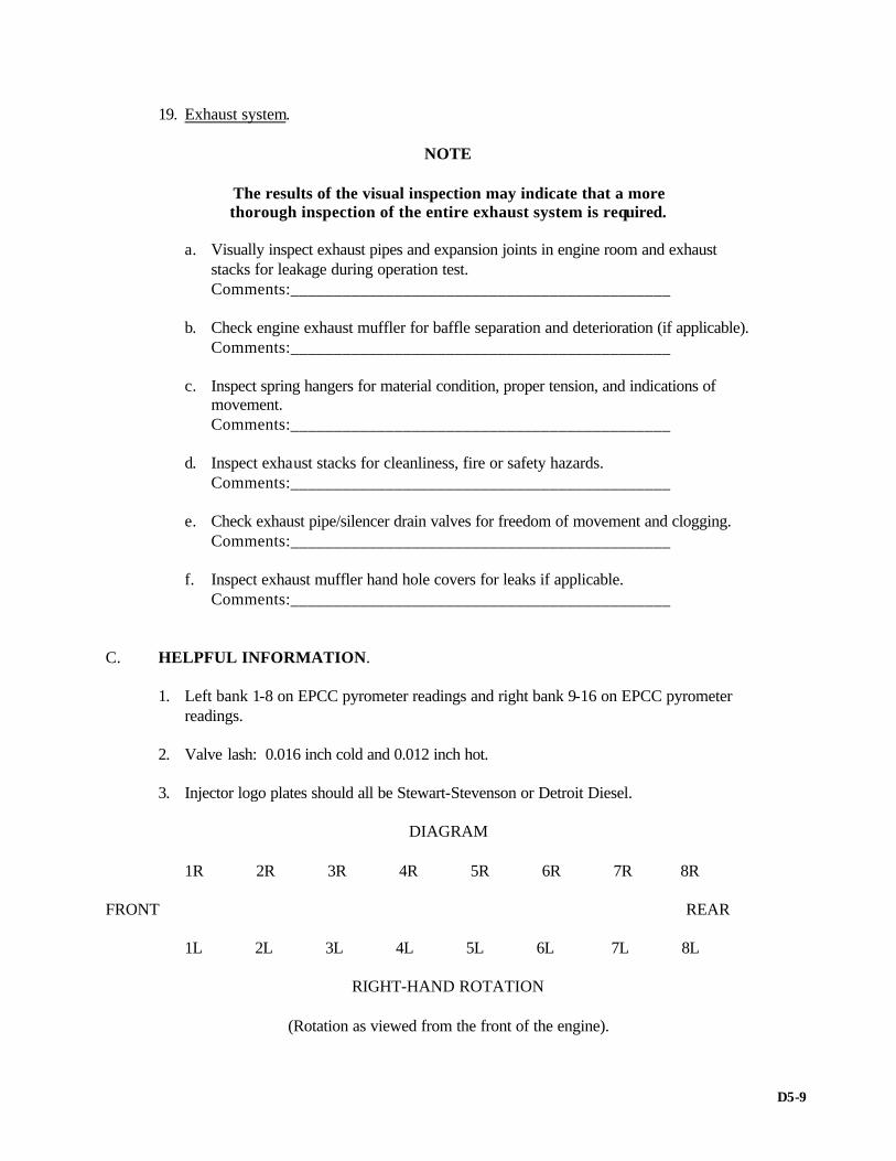
19. Exhaust system.
NOTE
The results of the visual inspection may indicate that a more thorough inspection of the entire exhaust system is required.
a. Visually inspect exhaust pipes and expansion joints in engine room and exhaust
stacks for leakage during operation test. Comments:____________________________________________ b. Check engine exhaust muffler for baffle separation and deterioration (if applicable). Comments:____________________________________________ c. Inspect spring hangers for material condition, proper tension, and indications of
movement. Comments:____________________________________________
d. Inspect exhaust stacks for cleanliness, fire or safety hazards. Comments:____________________________________________ e. Check exhaust pipe/silencer drain valves for freedom of movement and clogging. Comments:____________________________________________ f. Inspect exhaust muffler hand hole covers for leaks if applicable. Comments:____________________________________________ C. HELPFUL INFORMATION. 1. Left bank 1-8 on EPCC pyrometer readings and right bank 9-16 on EPCC pyrometer readings. 2. Valve lash: 0.016 inch cold and 0.012 inch hot. 3. Injector logo plates should all be Stewart-Stevenson or Detroit Diesel.
DIAGRAM 1R 2R 3R 4R 5R 6R 7R 8R FRONT REAR 1L 2L 3L 4L 5L 6L 7L 8L
RIGHT-HAND ROTATION
(Rotation as viewed from the front of the engine).
D5-9

SMALL, HIGH-SPEED DIESEL ENGINE SECURED-PHASE INSPECTION WORKSHEET
USS_________________________ DATE_______________________ ENGINE NO._________________ A. SPECIAL TOOLS
NOTE
Inspect a minimum of 25 percent of the following tools. 1. Appropriate size micrometers inside and outside (0 to 8 inches). Comments:____________________________________________ 2. Depth micrometer (0 to 3 inches). Comments:____________________________________________ 3. Crankshaft deflection gage. Comments:____________________________________________ 4. Dial indicator. Comments:____________________________________________ 5. Magnetic base for dial indicator. Comments:____________________________________________ 6. Feeler gages (long & short). Comments:____________________________________________ 7. Hand or strobe tachometer. Comments:____________________________________________ 8. Valve spring compressor. Comments:____________________________________________ 9. Ring compressor. Comments:____________________________________________ 10. Puller group, liner. Comments:____________________________________________ 11. Wrench, main bearing cap. Comments:____________________________________________
D6-1

12. Ring expander. Comments:____________________________________________ 13. Applicable tune-up kits (J-tools). Comments:____________________________________________ 14. Puller group, camshaft. Comments:____________________________________________ 15. Wrench, standard tool set. Comments:____________________________________________ 16. Main bearing removal tool. Comments:____________________________________________ 17. Jacket water test kit. Comments:____________________________________________ 18. Lube oil test kit. Comments:____________________________________________ 19. Jacking gear. Comments:____________________________________________ 20. Hand-held pyrometer. Comments:____________________________________________ 21. Fuel jumper line wrenches. Comments:____________________________________________ 22. J-tools: Tool Number Description J 23410 Torque multiplier J 1264-01 Torque wrench 0-200 ft-lb J 23775 Torque wrench 100-600 ft-lb J 24407 Torque wrench 10-250 ft lb J 8398 Torque wrench 0-500 ft-lb J 25310 Tube bender J 8051-01 Tubing flare kit J 9708-01 Valve lash feeler gage set Comments:____________________________________________
D6-2

B. VISUAL INSPECTION
NOTE
Some of the procedures includes in these requirements assume access to the crankcase, but some small engines have no such
access. Mark comment not appropriate (NA) as applicable. Additional generic requirements may also not apply to a specific
application of the small high-speed diesel engine. 1. Crankcase and block. a. Check for missing or loose bolts, block to base. Comments:____________________________________________ b. Check internals for discoloration of signs of overheating. Comments:____________________________________________ c. Inspect main bearing and connecting-rod bolts and nuts for broken or missing cotter
pins. Comments:____________________________________________ d. Validate that with twin units (tandem) both engines trip at the same time. Comments:____________________________________________ e. Check for water dripping at liner to block sealing. Comments:____________________________________________ f. Check visible areas of liners for scoring, galling, and dull spots. Inspect rings for
excess carbon and/or broken rings. (Bar engine over for this operation.) Comments:____________________________________________ g. Check all lube oil piping for looseness. Comments:____________________________________________ h. Inspect accessory drive and crankshaft gear for broken teeth, unusual wear pattern,
excessive wear, and improper lubrication.
CAUTION
Use extreme care, as engine must be barred over several revolutions to inspect all gears. Comments:____________________________________________
D6-3

i. Inspect drive gears for broken teeth, unusual wear pattern, or excessive wear. Comments:____________________________________________
NOTE
Inspection may dictate backlash requirements. 2. Vibration damper/ring gear/pulleys. a. Check vibration damper for dents or bulges in the damper case; check mounting bolt
torque after removing cover. Comments:____________________________________________ b. Check flywheel ring gear teeth and air start motor pinion for cracking or pitting.
Inspect attached pulleys if installed. Comments:____________________________________________ 3. Camshaft. a. Inspect camshaft lobes for excessive pitting, flat spots, or wear. Comments:____________________________________________ 4. Fuel supply pump and fuel system. a. Inspect fuel supply pump for fuel leaks. Comments:____________________________________________ b. Check lube oil sample and, if required (i.e., diluted), pressurize engine fuel system to
determine source of leakage. Comments:____________________________________________ 5. Upper running assemblies. a. Spot check valve clearances and injector timing.
NOTE
Refer to operational logs to determine past performance and variations in exhaust temperatures.
Comments:____________________________________________ b. Check to ensure that control racks and settings are properly adjusted and that linkage
arm, pins, and clips are properly set. Comments:____________________________________________
D6-4

c. Check for any evidence of fuel or water leakage near the cylinder head. Comments:____________________________________________ 6. Fuel control linkage and governor assembly. a. Check freedom of movement of all linkages and control shafts. Comments:____________________________________________ b. Check all linkages for lost motion with clevis pin nuts securely tightened against
shoulders and all cotter keys in place. Comments:____________________________________________ c. Check governor for oil leakage around base or governor. Comments:____________________________________________ 7. Salt- and freshwater pumps. Remove the end plate on JABSCO pump and inspect
impeller for wear and cracks. a. Check for any leakage from the telltale hole and miscellaneous piping (leakage from
telltale holes indicates defective seals). b. Ensure that all vent valves and gages have been installed. Comments:____________________________________________ 8. Engine-driven lube oil pump (when accessible). a. Check for any leakage of oil at pipe connections and flanges. Comments:____________________________________________ b. Inspect for signs of paint peeling from pump housing. Comments:____________________________________________ 9. Turbocharger(s) (when installed). a. Inspect turbocharger compressor for damaged vanes or leaking oil seals. Comments:____________________________________________ b. Ensure that turbocharger rotor does not bind when rotated by hand. Comments:____________________________________________ c. Inspect external surface of the turbocharger for evidence of exhaust leaks. Comments:____________________________________________ d. Inspect turbocharger after cooler for dirt, oil, contamination, and jacket water leaks. Comments:____________________________________________
D6-5

10. Flexible hoses, flexible pipe, and fittings. a. Inspect flexible hose for cracks, crimping, fraying, rubbing, swelling, and
deterioration. Check for improper bend radii. Comments:____________________________________________ b. Inspect pipe sections for cracks or for leakage at flanges. Comments:____________________________________________ c. Inspect pipe hangers for tightness and correct settings, and inspect flexible pipes for
freedom of movement. Comments:____________________________________________ 11. Air intake system. a. Inspect filter elements for cleanliness, completeness; ensure that filter element is
firmly seated in housing and that differential gage has been installed and calibrated. Comments:____________________________________________ b. Inspect air ducting from filter to turbocharger air inlet for cracks, missing sections,
loose or missing nuts, bolts, and rivets. Comments:____________________________________________ 12. Safety devices. a. Remotely operate the emergency trip (inspect for frayed wire and improper
connectors). Comments:____________________________________________ b. Check the manual trip stop lever cap screw for tightness. Comments:____________________________________________ c. Check flange shields and spray shields for proper installation and condition. Comments:____________________________________________ 13. Prime mover. a. Validate alignment of prime mover if warranted.
NOTE
Administration inspection or previous performance (i.e., vibration problems) may dictate this requirement.
D6-6
14. Exhaust system.
NOTE
The results of the visual inspection may indicate that a more thorough inspection of the entire exhaust system is required.
a. Visually inspect exhaust pipes and expansion joints in engine room and exhaust
stacks for leaks during operational test. Comments:____________________________________________ b. Check engine exhaust muffler for baffle separation and deterioration (if applicable). Comments:____________________________________________ c. Inspect spring hangers for material condition, proper tension, and indications of
movement. Comments:____________________________________________ d. Inspect exhaust stacks for cleanliness, fire or safety hazards. Comments:____________________________________________ e. Check exhaust pipe/silencer drain valves for freedom of movement and clogging. Comments:____________________________________________ f. Inspect exhaust muffler hand hole covers for leaks if applicable. Comments:____________________________________________ 15. Lube oil filters. a. Inspect one filter element for excessive contaminants and correct installation. Comments:____________________________________________ b. Check lube oil sampling valves for hand wheels and caps. Comments:____________________________________________ 16. Fuel oil filters and strainers. a. Ensure that strainer T-handle turns freely. Comments:____________________________________________ b. Inspect filter and strainer drain valves for freedom of movement. Comments:____________________________________________ 17. Intake and exhaust manifolds. a. Inspect air and exhaust manifolds for evidence of blown-out gaskets. Comments:____________________________________________
D6-7
b. Check heat shields for proper installation. Comments:____________________________________________ 18. Heat exchangers and temperature-regulating valves. a. Inspect heat exchangers for external leaks. Comments:____________________________________________ b. Inspect temperature regulators for freedom of movement. Comments:____________________________________________
D6-8

ALL ABOVE VIEWS FROM REAR OF ENGINE
D6-9

Model Description, Rotation, and Accessory Arrangement
General Specifications
6V 8V 12V 16V Type 2 Cycle 2 Cycle 2 Cycle 2 Cycle Number of Cylinders 6 8 12 16 Bore (inches) 4.25 4.25 4.25 4.25 Bore (mm) 108 108 108 108 Stroke (inches) 5 5 5 5 Stroke (mm) 127 127 127 127 Compression Ratio (Nominal) (Standard Engines)
17 to 1 17 to 1 17 to 1 17 to 1
Compression Ratio (Nominal) (“N” Engines)
18.7 to 1 18.7 to 1 18.7 to 1 18.7 to 1
Total Displacement - cubic inches 426 568 852 1136 Total Displacement - liters 6.99 9.32 13.97 18.63 Number of Main Bearings 4 5 7 10
D6-10
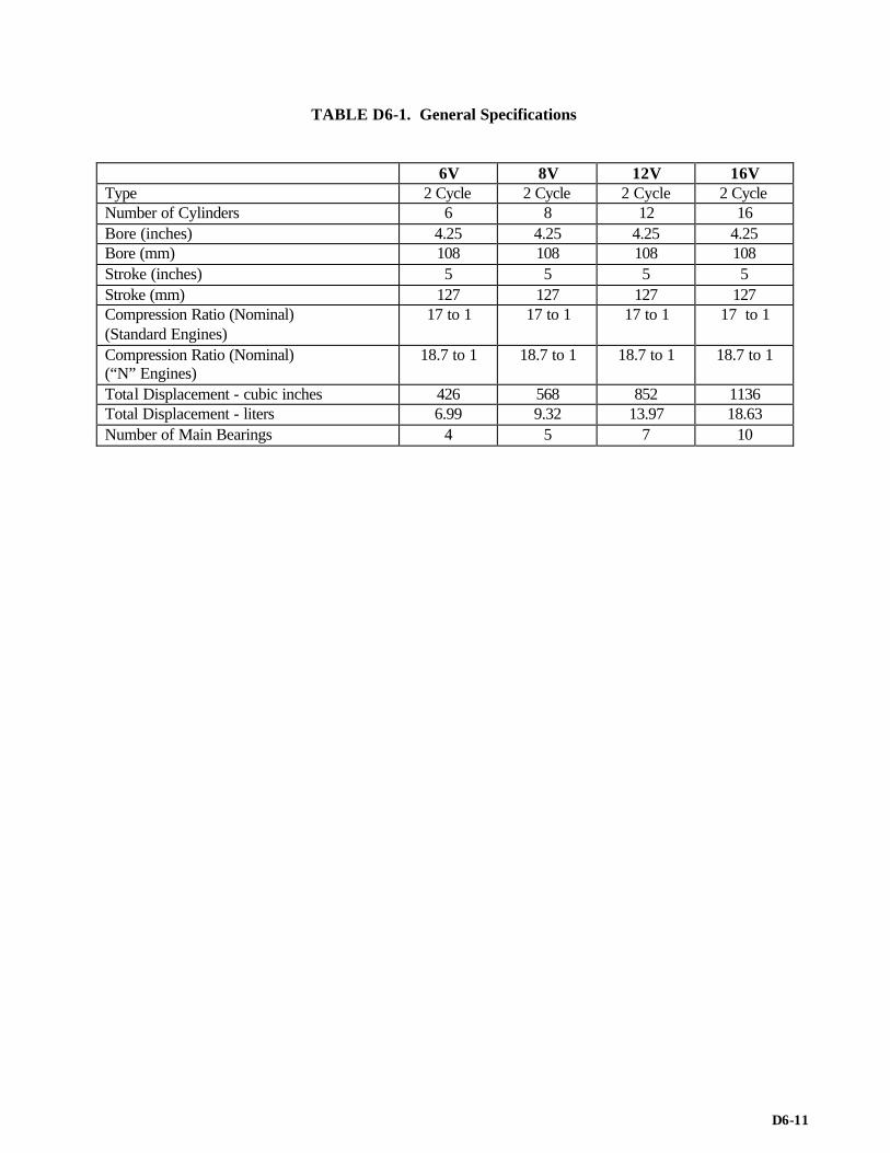
TABLE D6-1. General Specifications
6V 8V 12V 16V Type 2 Cycle 2 Cycle 2 Cycle 2 Cycle Number of Cylinders 6 8 12 16 Bore (inches) 4.25 4.25 4.25 4.25 Bore (mm) 108 108 108 108 Stroke (inches) 5 5 5 5 Stroke (mm) 127 127 127 127 Compression Ratio (Nominal) (Standard Engines)
17 to 1 17 to 1 17 to 1 17 to 1
Compression Ratio (Nominal) (“N” Engines)
18.7 to 1 18.7 to 1 18.7 to 1 18.7 to 1
Total Displacement - cubic inches 426 568 852 1136 Total Displacement - liters 6.99 9.32 13.97 18.63 Number of Main Bearings 4 5 7 10
D6-11

GENERIC MEDIUM-SPEED DIESEL ENGINE SECURED-PHASE INSPECTION WORKSHEET
USS DATE ENGINE NO. A. SPECIAL TOOLS
NOTE
Inspect a minimum of 25 percent of the following tools. Also review tools listed in PMS and the applicable technical manual.
1. Appropriate size micrometers inside and outside (0 to 11 inch). Comments: 2. Torque wrenches. a. 1/2-inch drive up to 350 ft./lb. Comments: b. 3/4-inch drive up to 100 ft./lb. Comments: c. 1/2-inch drive up to 200 ft./lb. Comments: 3. Crankshaft deflection gage. Comments: 4. Dial indicator. Comments: 5. Magnetic base for dial indicator. Comments: 6. Feeler gages (short). Comments: 7. Feeler gages (long). Comments: 8. Hand or strobe tachometer. Comments:
D7-1

9. Cylinder pressure gage (Kiene indicator). Comments: 10. Kiene indicator offset extension (if required). Comments: 11. Hand tools (PMS-related tools). Comments: 12. Injector test stand (pop tested). Comments: 13. Journal protector (leather strap). Comments: 14. Main bearing cap puller. Comments: 15. Main bearing rollout tools (main and thrust). Comments: 16. Main bearing wrenches. Comments: 17. Main bearing wrench adapter. Comments: 18. Piston ring expander. Comments: 19. Ring compressor. Comments: 20. Jacket water test kit. Comments: 21. Lube oil test kit. Comments: B. VISUAL INSPECTION. 1. Crankcase and block: a. Isolate expansion tank and hydrostatically test jacket water system according to PMS
if any of the following conditions exist: rust, excessive water and chemical makeup, water streaks, obvious external/internal leaks, and NOAP results.
Comments:
D7-2

b. Inspect engine foundation bolts for correct installation. Comments: c. Inspect for loose or missing bolts securing block to base. Comments: d. Inspect for cracks in base and block. Comments: e. Check condition of rings, pistons, and liners, Inspect for broken rings, blow-by etc.
on both sides of engine. Comments:
D7-3
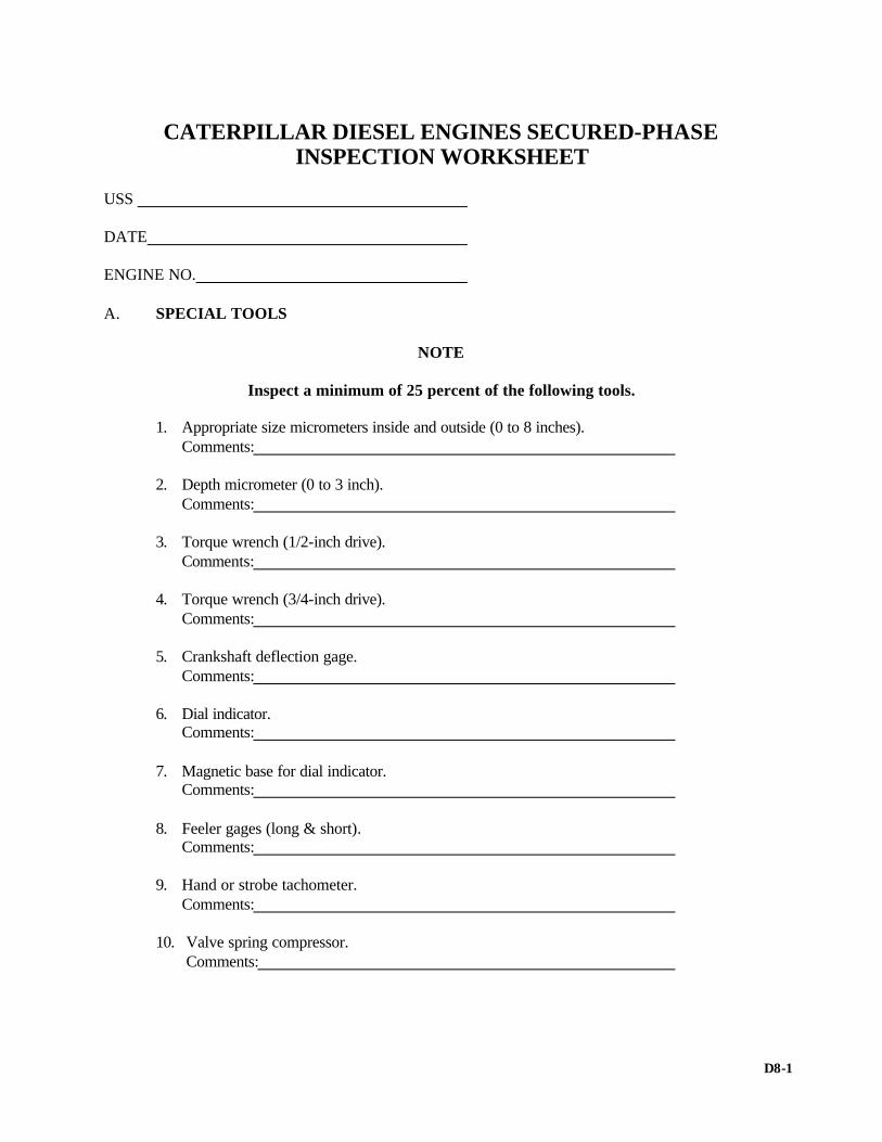
CATERPILLAR DIESEL ENGINES SECURED-PHASE INSPECTION WORKSHEET
USS DATE ENGINE NO. A. SPECIAL TOOLS
NOTE
Inspect a minimum of 25 percent of the following tools. 1. Appropriate size micrometers inside and outside (0 to 8 inches). Comments: 2. Depth micrometer (0 to 3 inch). Comments: 3. Torque wrench (1/2-inch drive). Comments: 4. Torque wrench (3/4-inch drive). Comments: 5. Crankshaft deflection gage. Comments: 6. Dial indicator. Comments: 7. Magnetic base for dial indicator. Comments: 8. Feeler gages (long & short). Comments: 9. Hand or strobe tachometer. Comments: 10. Valve spring compressor. Comments:
D8-1
11. Ring compressor. Comments: 12. Puller group liner. Comments: 13. Wrench, main bearing cap. Comments: 14. Ring expander. Comments: 15. Applicable tune-up kit. Comments: 16. Puller group, camshaft. Comments: 17. Wrench, precombustion chamber. Comments: 18. Wrench, fuel pump lifters. Comments: 19. Main bearing removal tool. Comments: 20. Jacket water test kit. Comments: 21. Lube oil test kit. Comments: B. VISUAL INSPECTION.
NOTE
Some of the procedures included in these requirements do not apply to a specific model caterpillar engine.
1. Crankcase and block: a. Check for missing or loose bolts, block to base. Comments: b. Check internals for discoloration or signs of overheating. Comments:
D8-2

c. Inspect main bearing and connecting rod bolts and nuts. Comments: d. Check connecting rod and main bearing edges for evidence of bearing failure. Comments: e. Check for water dripping at liner-to-block sealing surfaces. Comments:
f. Check visible areas of liners from beneath for scoring, galling, and dull spots. (Bar engine over for this operation.)
Comments: g. Check all lube oil piping for looseness. Comments: h. Run prelube pump and check to ensure that oil lines to the engine are tight. Check to
ensure that oil is reaching all rocker arm assemblies. Comments: i. Inspect accessory drive and crankshaft gear for broken teeth, unusual wear pattern,
excessive wear, and improper lubrication.
CAUTION
Use extreme care, as engine must be barred over several
revolutions to inspect all gears. Comments: j. Inspect drive gears for broken teeth, unusual wear pattern, or excessive wear. Comments: 2. Crankshaft vibration damper/ring gear. a. Check condition of the vibration damper for dents or bulges in the damper case. Comments: b. Check flywheel ring gear teeth and air start motor pinion for cracking or pitting. Comments: 3. Camshaft. a. Inspect camshaft lobes for excessive pitting, flat spots, or wear. Comments:
D8-3

4. Fuel injection pump and fuel lines. a. Inspect injection pump and fuel lines for leaks. Comments: b. Inspect cam roller for excessive wear or flat spots. Comments: c. Spot-check valve clearances. Comments: d. Inspect valve springs, valve locks, and rotators. Comments: e. Validate engine timing. Comments: f. Check for any excessive looseness in the rocker arm assemblies. Comments: 5. Cylinder head. a. Check for any evidence of fuel or water leakage around the cylinder head area. Comments: b. Thrust crankshaft and record (refer to the Tolerance Measurement Data Sheet,
appendix G8). Comments: c. Record crankshaft deflection readings in accordance with technical manual. Comments: 6. Fuel control linkage and governor assembly. a. Check freedom of movement of all racks, linkages, and control shafts. Comments:_____________________________________________
b. Check all linkage for lost motion with clevis pin nuts securely tightened against shoulders and all cotter keys in place.
Comments:_____________________________________________ c. Check governor oil level and oil leakage around base of governor. Comments:_____________________________________________ 7. Fuel pump timing. a. Check fuel pump timing on at least two cylinders on each bank. Comments:_________________________________________________
D8-4
8. Sea (raw) and jacket water pumps. a. Check for any leakage from the telltale hole and associated piping (leakage from
telltale holes indicates defective seals). Comments:______________________________________________ b. Ensure that all vent valves and gages have been installed. Comments:______________________________________________
9. Engine-driven lube oil pump. a. Check for any leakage of oil out of pipe connections and flanges.
Comments:______________________________________________ b. Check for signs of overheating on pump housing.
Comments:______________________________________________ 10. Turbocharger(s). a. Inspect turbocharger compressor for damaged vanes or leaking oil seal.
Comments:______________________________________________ b. Ensure that turbocharger rotor does not bind when rotated by hand.
Comments:______________________________________________ c. Inspect external surface of the turbocharger for evidence of exhaust leaks.
Comments:______________________________________________
d. Inspect turbocharger after cooler for dirt, oil, contamination, and jacket water leaks. Comments:______________________________________________
11. Flexible hose, flexible pipe, and fittings: a. Inspect flexible hose for cracks, crimping, fraying, rubbing, swelling, and
deterioration. Comments:______________________________________________
b. Inspect pipe sections for cracks or for leakage at flanges.
Comments:______________________________________________ c. Inspect pipe hangers for tightness and flexible pipes for freedom of movement.
Comments:______________________________________________ 12. Air intake system. a. Inspect filter elements for cleanliness, completeness; ensure that filter element is
firmly seated in housing and that the pop-up indicators have been installed. Comments:______________________________________________
D8-5
b. Inspect air ducting from filter to turbocharger air inlet for cracks, missing sections, loose or missing nuts, bolts, and rivets.
Comments:______________________________________________ 13. Safety devices. a. Remotely operate the emergency trip (inspect for frayed wire and improper
connectors). Comments:______________________________________________
b. Check the manual trip stop lever cap screw for tightness.
Comments:______________________________________________ c. Check flange shields and spray shields for proper installation and condition.
Comments:______________________________________________ d. Check high-temperature and low-lube-oil alarms.
Comments:______________________________________________ 14. Prime mover. a. Validate alignment of prime mover if indications warrant (i.e., vibration problems).
Comments:______________________________________________ 15. Exhaust system.
NOTE
The results of the visual inspection may indicate that a more thorough inspection of the entire exhaust system is required.
a. Visually inspect exhaust pipes and expansion joints in engine room and exhaust stacks for leaks during operational test.
Comments:______________________________________________
b. Check engine exhaust muffler for baffle separation and deterioration (if applicable).
Comments:____________________________________________ c. Inspect spring hangers for material condition, proper tension, and
indications of movement. Comments:______________________________________________
d. Inspect exhaust stacks for cleanliness, fire or safety hazards.
Comments:______________________________________________
D8-6

e. Check exhaust pipe/silencer drain valves for freedom of movement and clogging.
Comments:______________________________________________ f. Inspect exhaust muffler hand hole covers for leaks if applicable.
Comments:______________________________________________ 16. Lube oil filters. a. Inspect one filter element for excessive contaminants and correct
installation. Comments:______________________________________________
b. Check lube oil sampling valves for hand wheels and caps.
Comments:______________________________________________ 17. Fuel oil filters and strainers. a. Ensure that strainer T-handle turns freely.
Comments: ___________________________________________
b. Operate filter and strainer drain valves for freedom of movement. Comments:_________________________________________
18. Inspect intake and exhaust manifolds. a. Inspect air and exhaust manifolds for evidence of blown-out
gaskets. Comments:______________________________________________
b. Check heat shields for proper installation.
Comments:______________________________________________ 19. Heat exchangers. a. Inspect heat exchangers for external leaks.
Comments:______________________________________________
D8-7

WAUKESHA DIESEL ENGINES SECURED-PHASE INSPECTION WORKSHEET
USS DATE ENGINE NO. A. SPECIAL TOOLS
NOTE
Inspect a minimum of 25 percent of the following tools. 1. Appropriate size micrometers (inside and outside). Torque wrenches (inch and ft-lb). Comments: 2. Dial indicator and clamping device. Comments: 3. Feeler gage (long and short lengths). Comments: 4. Hand or strobe tachometer. Comments: 5. Hand tools. Comments: 6. Piston ring compressor. Comments: 7. Piston ring expander. Comments: 8. Cylinder liner removal tool. Comments: 9. Engine barring tool. Comments: 10. Lube oil test kit. Comments:
D9-1

11. Water inhibitor test kit. Comments: 12. Flywheel lifting tool. Comments: 13. Accessory drive gear puller and adapters (standard Navy puller tool). Comments: 14. Fuel injection line wrench. Comments: 15. Injector setting tool. Comments: 16. Compression tester. Comments: 17. Hand-held pyrometer. Comments: B. VISUAL INSPECTION.
NOTE
Some of the procedures included in these requirements do not apply to all Waukesha diesel engines. Ship configuration differences (i.e., MSO/MCM) also change inspection requirements. Mark the procedure "N/A" where it does not apply.
1. Block and engine foundation. a. Inspect engine foundation for cracks and separations from the engine.
Comments:______________________________________________ b. Sound the engine hold down bolts. Inspect for loose or missing bolts. Comments:______________________________________________ c. Inspect for cracked or missing chock fast and other bearing materials used between
engine and foundation. Comments:______________________________________________ d. Inspect for installation of collision chocks or other restraining devices. Determine
standoff distance. Measure clearance at each location and record results. Comments:______________________________________________
D9-2

e. Damper end of engine and power take-off end—Inspect all accessory hold-down bolts for tightness. Inspect for oil, water, and fuel leaks. Inspect for chafed lines and integrity of hold-down retaining devices.
Comments:______________________________________________ f. Inspect engine block for indications of oil leaks and cracks.
NOTE
Inspect high-stress areas of casing. Look for cracks in corners and hand hole covers.
Comments:______________________________________________
g. Inspect all water, fuel, oil, air, and hydraulic lines for leakage and chafing. Inspect
rubber and flexible lines for wear and deterioration. Comments:______________________________________________
h. Inspect under valve covers for fuel and water leakage.
Comments:______________________________________________
NOTE
Correct fuel and lube oil leaks immediately, and cite water leaks that are minor to the responsible engineering personnel. Correct leaks before operation.
2. Viscous damper.
a. Inspect viscous damper for indications of bulges, cracks, elongated boltholes, and bolt tightness.
NOTE Dents in the viscous damper or oil leaks are cause for rejection.
Comments:______________________________________________ 3. Turbocharger.
a. Check the turbocharger for oil, air, and exhaust leaks. Remove air filter and inlet silencer and inspect the inlet of the turbocharger for dirt, damage, and abnormal conditions. Check turbochargers for damaged vanes, leaking oil seal, freedom of movement.
Comments:______________________________________________
D9-3
4. Air inlet shutdown device. a. Check condition and operation, reset. Comments:______________________________________________ 5. Air intake system.
a. Check to be sure that all air cleaners have been securely mounted and all connections are tight.
Comments:______________________________________________ b. Open drain petcocks in air cleaners (MCM) and air intake manifolds (L1616DSIN) to
check for presence of water. Comments:______________________________________________ c. Inspect air ducting (inlet to turbocharger) for cracks, missing sections, loose or
missing fasteners. Comments:______________________________________________ 6. Engine Instrumentation.
a. Verify the calibration of engine instrumentation and condition of instruments. Comments:______________________________________________ 7. Lower Crankcase. Lower crankcase inspection (engines with hand-hole covers). Remove hand-hole covers
from each side of engine. Conduct the following inspection procedures:
a. Thrust crankshaft and record total thrust (end play). (Refer to Tolerance Measurement Data Sheet, appendix G9.)
Comments:______________________________________________ b. Inspect for evidence of bearing wear, flashing, abnormal conditions such as
disassembly, improper parts match of components, loose bolts and/or loose studs. Comments:______________________________________________ c. Inspect lower portion of cylinder liners for abnormal wear. Record results. Comments:______________________________________________ d. Inspect sump for foreign materials. Comments:______________________________________________ e. if warranted (i.e., oil analysis) inspect main bearings. If only one main bearing is
inspected, it should be no. 4. Comments:______________________________________________
D9-4

f. Measure and record L.O. pump backlash (refer to Tolerance Measurement Data Sheet, appendix G9).
Comments:______________________________________________ 8. Upper running gear. a. Check timing.
NOTE
Four-stroke cycle requires two complete revolutions of the crankshaft for timing. The power assembly must be on the compression stroke (intake/exhaust valves closed) during timing checks. Only one cylinder per 60 degrees of crankshaft rotation can be timed at one time.
Comments:______________________________________________
b. Conduct intake and exhaust valve clearance check. Measure clearances and record. Comments:______________________________________________
c. Inspect for fuel line leakage.
Comments:______________________________________________ d. Inspect the control shaft flexible coupling and rack return springs for proper
installation or settings. Comments:______________________________________________
e. Check installation of all rack stops and rack movement. All rack stops must be the
same width. Comments:______________________________________________
f. Check the actuator arm linkage (MSO) and that the cross-rod adjustment is correct
according to the technical manual. (Refer to the Tolerance Measurement Data Sheet, appendix G9.)
Comments:______________________________________________ 9. Fuel system. a. Check for obvious leaks at the pump and filter.
Comments:______________________________________________ b. Check fuel filter handle for freedom of movement.
Comments:______________________________________________ c. Open the drain petcock on the fuel oil strainer to check for water from the separator.
Check the window screen for cleanliness. Comments:______________________________________________
D9-5

d. Check and record fuel oil pump backlash. (Refer to the Tolerance Measurement Data
Sheets, appendix G9). Comments:______________________________________________
10. Lube oil system. a. Manually start the prelube system from local and remote control to check operation.
Check lights (prelube is on). Comments:______________________________________________
b. Check for any oil leaks at the pipe connections and flanges.
Comments:______________________________________________ 11. Safety device. a. Activate the manual shutoff lever locally (MSO), locally/remote (MCM).
NOTE
Reset the lever at the engine.
Comments:______________________________________________ b. Check the operation of the temperature control manual override on the surge tank.
NOTE
Be sure that control is returned to the normal position.
Comments:______________________________________________ c. Check the flange shields and spray shields for proper installation and condition.
Comments:______________________________________________ 12. General. a. Validate the alignment of the prime mover if warranted (last PMS readings, vibration
problems, etc. may dictate this requirement). Comments:______________________________________________
b. Check the backlash of the generator oil scavenging pump gear. (Refer to the
Tolerance Measurement Data Sheet, appendix G9.) Comments:______________________________________________
c. Check the condition of the epoxy chocks below the engine rails for damage and
cracking. Comments:______________________________________________
D9-6

d. Check the engine foundation bolts for tightness, missing bolts, or improper installation.
Comments:______________________________________________ 13. Exhaust system.
NOTE
The results of the visual inspection may indicate that a more thorough inspection of the entire exhaust system is required.
a. Visually inspect exhaust pipes and expansion joints in engine room and exhaust
stacks for leaks during operational test. Comments:______________________________________________
b. Check engine exhaust muffler for baffle separation and deterioration (if applicable).
Comments:______________________________________________ c. Inspect spring hangers for material condition, proper tension, and indications of
movement. Comments:______________________________________________
d. Inspect exhaust stacks for cleanliness, fire or safety hazards.
Comments:______________________________________________ e. Check exhaust pipe/silencer drain valves for freedom of movement and
clogging. Comments:______________________________________________
f. Inspect exhaust muffler hand hole covers for leaks if applicable.
Comments:______________________________________________ 14. Heat exchangers. a. Inspect heat exchangers for external leaks.
Comments:______________________________________________ C. IDENTIFICATION/NUMBERING 1. Establish the right and left sides of the engines by standing at the rear or flywheel
end and facing the engine. 2. Cylinders are numbered one to six in each bank, starting from the front gear
cover, so any reference should designate either right or left bank (for example: 1R, 2R, 3R, 4R, 5R, and 6R for the right bank, and 1L, 2L, 3L, 4L, 5L, and 6L for the left bank).
D9-7

3. Front and rear are designated as antiflywheel (front) and flywheel (rear) ends.
CAUTION
All engines on MSO class vessels and generator set engines on MCM class vessels are CW rotation; propulsion engines on MCM I and II vessels, however, are CCW rotation.
4. CW rotation is clockwise rotation as viewed facing the flywheel end of the engine;
CCW rotation is counterclockwise rotation as viewed facing the flywheel end of the engine.
5. Firing order (CW rotation engines): 1L, 6R, 4L, 3R, 2L, 5R, 6L, 1R, 3L, 4R, 5L, 2R (CCW rotation engines): 1R, 6L, 5R, 2L, 3R, 4L, 6R, 1L, 2R, 5L, 4R, 3L
D9-8
ISOTTA FRASCHINI (IF) SPECIAL TOOLS CHECK SHEET
USS HULL NO. ________________________________ DATE A. SPECIAL TOOLS 1. Liner extractor 186000001A01 Comments: __________________________________________ 2. Cylinder lapper 185000001A01 Comments: __________________________________________ 3. Holder, comparator liner projection 185000095A01 Comments: __________________________________________ 4. Borescope, cylinder inspection Comments: __________________________________________ 5. Pin for cylinder head and gasket alignment 72937F01 Comments: __________________________________________ 6. Gage for nozzle protrusion 140000008A01 Comments: __________________________________________ 7. Diametric wrench kit 185000039A01 Comments: __________________________________________ 8. Socket wrench EFEP 346 Comments: __________________________________________ 9. Graduated timing sequence disc 185000051A01 Comments: __________________________________________ 10. Extractor main bearing cap 185000096A01 Comments: __________________________________________ 11. Con-rod cap alignment tool 185000024A01 Comments: __________________________________________ 12. Pliers to remove piston rings 185000054A01 Comments: __________________________________________ 13. Puller for planetary gear 185000035A01 Comments: __________________________________________
D10-1

14. Extractor drive shaft coupling half inj pump 185000057A01 Comments: __________________________________________ 15. Adaptor for compression test 185000059A01 Comments: __________________________________________ 16. Motor meter recording cyl comp tester 1854000060A01 Comments: __________________________________________ 17. Micrometer 0-25 mm 185000065A01 Comments: __________________________________________ 18. Micrometer 25-50 mm 185000066A01 Comments: __________________________________________ 19. Micrometer 50-75 mm 185000067A01 Comments: __________________________________________ 20. Micrometer 100-125 mm 185000068A01 Comments: __________________________________________ 21. Micrometer 125-150 mm 185000069A01 Comments: __________________________________________ 22. Micrometer 150-175 mm 185000093A01 Comments: __________________________________________ 23. Micrometer 175-200 mm 185000094A01 Comments: __________________________________________ 24. Depth micrometer Comments: __________________________________________ 25. Dial indicator Comments: __________________________________________ 26. Lube oil-testing equipment Comments: __________________________________________ 27. Jacket water testing equipment Comments: __________________________________________ 28. Flow tube for flow checking inj pmp Comments: __________________________________________ 29. Valve recession tool (VRT) Comments: __________________________________________
D10-2

30. Feeler gages (short) Comments: __________________________________________ 31. All tools required to complete PMS Comments: __________________________________________ B. VISUAL INSPECTION OF ENGINE 1. Crankcase and block. a. Check for missing or loose bolts, block to rails, and rails to sub base. Comments: __________________________________________ b. Check for oil leaks at gasket area between block and oil pan. Comments: __________________________________________ c. Check for cracks on sub base in the area between engine and generator. Comments: __________________________________________
NOTE
If oil pan is removed, inspector should continue with the following: d. Check internals for discoloration or signs of overheating. Comments: __________________________________________ e. Check for water dripping at liner to block sealing. Comments: __________________________________________ f. Check for visible areas of liners for scoring, galling, dull spots, and glazing. Comments: __________________________________________ g. Check all lube oil piping and brackets for looseness and cracks. Comments: __________________________________________ h. Check the condition of piston cooling tubes for possible contact with connecting rods. Comments: __________________________________________
NOTE
If lube oil duplex pump is removed, inspector should continue with the following:
i. Inspect lube oil pump drive gears for broken teeth, unusual wear pattern, excessive
wear, signs of nitriding, spalling, and evidence of improper lubrication. Comments: __________________________________________ j. Inspect condition of oil pump idler gear assembly bolt. Comments: __________________________________________
D10-3
k. Ensure pump turns freely without binding. Comments: __________________________________________ l. Inspect crankshaft gear for broken teeth, unusual wear pattern, excessive wear, signs
of nitriding, spalling, and evidence of improper lubrication. Comments: __________________________________________
CAUTION
Use extreme care, as engine must be barred over to fully inspect gear.
2. Vibration damper/flywheel ring gear. a. Check vibration damper for dents or bulges in the dampener case. (Also check for oil
leaks at seams of case.) Comments: __________________________________________ b. Check flywheel ring gear teeth and air start motor pinion for excessive wear, cracking
or pitting. Comments: __________________________________________ 3. Fuel supply pump and fuel system. a. Inspect fuel supply pump for leaks. Check tell-tale line for signs of fluid. Comments: __________________________________________ b. Check lube oil sample and, if required (i.e., diluted), determine source of leakage.
Check seal area of engine mounted primary fuel oil pump along with having fuel nozzle tested.
Comments: __________________________________________ 4. Cylinder heads. a. Check for evidence of fuel, water, and lube oil or combustion gas leakage around area
of cylinder heads. Comments: __________________________________________ b. Check valve lash clearances. Record clearances as found prior to making
adjustments. Comments: __________________________________________ c. If warranted, by either hours IAW class advisory for checking valve recession or
PMS not being completed within periodicity for checking valve lash, conduct a set of valve recession readings and check guide post height readings. Record results.
Comments: __________________________________________
D10-4

d. Remove fuel injection nozzles and perform borescope inspection of all cylinders, check the condition of cylinder liners, piston crowns and heads. If evidence of water intrusion is suspect, conduct a jacket water system hydro and re-borescope.
Comments: __________________________________________
CAUTION
Use extreme care, as engine must be barred over in order to
inspect all cylinders.
NOTE
Evidence of water residue may indicate a failed cylinder head or cylinder head gasket.
5. Fuel control linkage and governor assembly. a. Check freedom of movement of all linkages and control shafts. Comments: __________________________________________ b. Check all linkages for ease of motion with clevis pin nuts securely tightened against
shoulders. Comments: __________________________________________ c. Check for oil leakage around governor or base. Comments: __________________________________________ 6. Salt and jacket water pumps.
NOTE
Refer to operational logs to determine any excessive degradation of operating pressure in jacket water and salt water systems.
a. Check for any leakage on the jacket water pump from the tell-tale hole. (Leakage from tell-tale hole indicates defective mechanical seals.)
Comments: __________________________________________ b. Ensure all gages and gage cut out valves have been installed. Comments: __________________________________________ c. Inspect salt water pump drive and belt in accordance with current PMS. Comments: __________________________________________
D10-5

7. Turbochargers. a. Inspect turbocharger compressor for damaged vanes or leaking oil seal. Comments: __________________________________________ b. Ensure that turbocharger rotor does not bind when rotated by hand. Comments: __________________________________________ c. Inspect external surface of the turbocharger for evidence of exhaust leaks, oil leaks or
housing cracks. Comments: __________________________________________ 8. Air intake system.
a. Inspect filter elements for cleanliness and completeness. Ensure that filter element is firmly seated in housing and that manometer gage has been installed.
Comments: __________________________________________ b. Inspect air ducting from filter to turbocharger air inlet for cracks, missing sections,
loose or missing nuts, bolts, and clamps. Comments: __________________________________________ 9. Intake and Exhaust Manifolds. a. Inspect air and exhaust manifolds for evidence of blown out gaskets. Comments: __________________________________________ b. Ensure that air manifold/intercooler tell-tale drilled plugs are unobstructed. Check
for signs of excessive oil tell-tale plugs. Comments: __________________________________________
NOTE
If water is leaking from tell-tale plug, hydro jacket water system and borescope intercooler.
c. Check turbocharger heat shields and exhaust system lagging for proper installation.
Comments: __________________________________________ 10. Exhaust System.
NOTE
The results of the visual inspection may indicate that a more thorough inspection of the entire exhaust system is required.
D10-7

a. Visually inspect exhaust pipes and expansion joints in the engine room and exhaust stacks for leaks during operational test.
Comments: __________________________________________ b. Inspect exhaust stacks for cleanliness, fire or safety hazards. Comments: __________________________________________ c. Check exhaust pipe/silencer drain valves for freedom of movement and clogging. Comments: __________________________________________ 11. Flexible hoses, flexible pipe and fittings. a. Inspect flexible hoses for cracks, crimping, fraying, rubbing, swelling, and
deterioration. Check inspection tags ensuring hoses are within current guidance for periodicity.
Comments: __________________________________________ b. Inspect pipe sections for cracks or leakage at flanges. Comments: __________________________________________ 12. Safety devices. a. Remotely operate the emergency trip (inspect for frayed wire and improper
connections). Comments: __________________________________________ b. Check flange shields and spray shields for proper installation and condition. Comments: __________________________________________ c. Validate that by moving AMOT valve manual operation lever through both detents
proper shutdown operation of the injection pump control rack and air flaps is achieved.
Comments: __________________________________________ 13. Lube oil filters. a. Cut open filter elements and inspect for excessive contaminants. Ensure new filter
elements are installed correctly. Comments: __________________________________________ 14. Fuel oil filters. a. Ensure that duplex filter T-handle turns freely. Comments: __________________________________________ b. Inspect duplex filter and Salamini fuel/water separator filter drain valves for freedom
of movement. Comments: __________________________________________
D10-8

c. Inspect filter elements for excessive contaminants and correct installation. Comments: __________________________________________ d. Ensure Salamini filter water indicator ball is in bottom of sight glass (ball only floats
in water). Comments: __________________________________________ 15. Heat exchanger housing and temperature-regulating valves. a. Inspect heat exchanger housing for external leaks. Comments: __________________________________________ b. Inspect temperature regulator indicators for freedom of movement. Comments: __________________________________________
NOTE
Jacket water/seawater heat exchanger thermostatic valves have indicators with graduated pins, which will indicate between 3rd
and 9th mark during normal operation. Failed valves will probably remain on first mark.
16. Prime mover. a. Validate alignment of prime mover ONLY IF WARRANTED.
NOTE
Administration inspection or previous performance (i.e., vibration problems, excessive heat from coupling, failure of
spring pack, cracked sub base) may dictate this requirement. Comments: __________________________________________
17. Additional (when accessible or if warranted). a. Inspect drive gears for broken teeth, unusual wear pattern, excessive wear and signs
of nitriding spalling. Check backlash between gears. Comments: __________________________________________
NOTE
Inspection may dictate backlash requirement.
b. Measure crankshaft thrust. Comments: __________________________________________
D10-9

c. Inspect camshaft lobes for excessive pitting, flat spots or wear. Measure camshaft endplay.
Comments: __________________________________________ d. Inspect tappets for excessive wear. Comments: __________________________________________ 18. Cold/Hot checks. a. Conduct a complete set of cold and hot checks. Comments: __________________________________________
D10-10

PAXMAN VALENTA (16RP200M) SECURE PHASE INSPECTION WORKSHEET
USS DATE _____ ENGINE NO. ______________________________ A. SPECIAL TOOLS
NOTE
Inspect a minimum of 25 percent of the following tools.
1. Fuel injection pump gap gauge. Comments: __________________________________________ 2. Fuel rack calibration setting pins. Comments: __________________________________________ 3. Heel type pinch bar for injector removal. Comments: __________________________________________ 4. Fuel injector nozzle cleaning kit. Comments: __________________________________________ 5. Fuel pump camshaft timing adjuster. Comments: __________________________________________ 6. Dummy nozzle for top dead center check of piston. Comments: __________________________________________ 7. Special feeler gauge 0.005 for intake tappet clearance. Comments: __________________________________________ 8. Special feeler gauge 0.020 for exhaust tappet clearance. Comments: __________________________________________ 9. Torque wrench 10 to 50 lb/ft. Comments: __________________________________________ 10. Torque wrench 50 to 250 lb/ft. Comments: __________________________________________
D11-1

11. Metric tool set open end, box end and sockets for routine maintenance. Comments: __________________________________________ 12. Internal and external circlip pliers. Comments: __________________________________________ B. VISUAL INSPECTION 1. Crankcase and block. a. Inspect block for missing or loose bolts. Comments: __________________________________________ b. Inspect internals for discoloration and signs of overheating. Comments: __________________________________________ c. Inspect for foreign material in crankcase. Comments: __________________________________________ d. Inspect crankcase covers for missing bolts, loose fasteners, or missing gaskets. Comments: __________________________________________ e. Inspect crankcase relief valves cover springs for distortion and collapse. Comments: __________________________________________ f. Inspect connecting rod and main bearing edges for signs of bearing failure. Comments: __________________________________________ g. Inspect forked connecting rod bolts for proper stretch. Comments: __________________________________________ h. Check the balance weights for security. Comments: __________________________________________ i. Check crankcase deflections (drive end). Record on data sheet. Comments: __________________________________________ j. Inspect for crankcase block cracks. Comments: __________________________________________ 2. Ring gear and pulleys. a. Inspect flywheel gear teeth and both starter pinion gear teeth for cracking, pitting, and
excess wear. Comments: __________________________________________ b. Inspect raw water pump and engine pulleys for dents or cracks. Comments: __________________________________________
D11-2

c. Inspect pulley vee belts for cracks and deterioration. Comments: __________________________________________ 3. Cylinder Head. a. Inspect for missing, damaged and loose valve spring circlip. Comments: __________________________________________ b. Inspect for broken valve springs and valve bridges. Comments: __________________________________________ c. Inspect for loose or damaged cylinder head bolts. Comments: __________________________________________ d. Inspect lube oil drain ferrules (no paint and properly greased). Comments: __________________________________________ e. Inspect for evidence of water and fuel leakage around cylinder heads. Comments: __________________________________________ f. Check tappet clearance using a feeler gauge. Note: Tappet adjustment indicating
should be used to indicate Piston TDC compression stroke. Record on data sheet. Comments: __________________________________________ g. Inspect cylinder heads for cracking. Comments: __________________________________________ 4. Fuel System.
NOTE
To inspect fuel pump camshafts for proper timing, a dummy injector and timing tool must be used.
a. Inspect fuel pump camshafts for proper timing. Comments: __________________________________________ b. Check all fuel injection pump return springs for security and distortion. Comments: __________________________________________ c. Inspect coalescer and duplex filters for signs of leakage. Comments: __________________________________________ d. Ensure that the Duplex fuel filter-shifting device operates properly. Comments: __________________________________________ e. Inspect uniformity of fuel rack setting. Comments: __________________________________________
D11-3

f. Inspect freedom of movement of all rack linkages and control shafts. Comments: __________________________________________ g. Inspect under fuel injection pump bellows for leakage from the control rod oil seals. Comments: __________________________________________ h. Check internal of coalescer and duplex filter for contamination. Comments: __________________________________________ i. Examine the fuel reservoir stages for deposit or foreign matter and the air bleed slot
between compartments for obstruction. Comments: __________________________________________ j. Inspection fuel oil reservoir relief valve; ensure that the valve slides smoothly in the
carrier bore and the relief spring is not collapsed or distorted. Comments: __________________________________________ 5. Exhaust System. a. Inspect expansion bellows for pinholes, cracks, and burning. Comments: __________________________________________ b. Inspect heat shields for proper installation and deterioration. Comments: __________________________________________ 6. Air Intake System. a. Inspect air intake clamp bands for proper fit or deterioration. Comments: __________________________________________ b. Inspect ends of air pipes for wear, fretting, or cracking. Comments: __________________________________________ c. Inspect for proper operation of air shutdown valve. Comments: __________________________________________ d. Inspect air filter element for cracks, welding failure, cleanliness, and completeness;
ensure that filter is firmly seated in housing. Comments: __________________________________________ e. Inspect condensate drain valves and spring for dirt, corrosion and deterioration. Comments: __________________________________________ f. Inspect charge air cooler for dirt, fin damage, oil contamination, and water leaks. Comments: __________________________________________ 7. Turbocharger. a. Ensure Turbocharger inducer blades are not binding. Comments: __________________________________________
D11-4
b. Inspect turbocharger compressor rotating assembly for oil seal leakage. Comments: __________________________________________ c. Check turbocharger inducer to blower inlet casing clearance. Record on data sheet. Comments: __________________________________________ d. Inspect external surface of turbocharger for evidence of lube oil, exhaust gas and
jacket water leaks. Comments: __________________________________________ e. Inspect turbocharger blade for deterioration. Comments: __________________________________________ 8. Lube Oil System. a. Inspect duplex filter shifting handle for freedom of movement. Comments: __________________________________________ b. Remove and inspect lube oil filter for contaminants such as metal particles. Comments: __________________________________________ c. Run prelube pump and ensure that the lube oil reaches the turbocharger oil supply
inlet. Comments: __________________________________________ d. Ensure hand operated lube oil priming pump is operational. Comments: __________________________________________ e. Check lube oil level in sump after engine has been shutdown for at least 20 minutes.
Maintain at "max static" mark on dipstick. Comments: __________________________________________ 9. Cooling System.
NOTE
To inspect fuel pump camshafts for proper timing, a dummy injector and timing tool must be used.
a. Inspect raw water pump drive belts for proper tension. Comments: __________________________________________ b. Inspect jacket water pump telltale line for leakage or blockage. (Leakage from
telltale lines indicate defective mechanical seals.) Comments: __________________________________________
D11-5

c. Check heat exchanger and lube oil cooler for coolant leakage. Comments: __________________________________________ d. Inspect all external coolant lines and flanges for leaks. Comments: __________________________________________ e. Inspect heat exchanger zinc anodes for deterioration. Comments: __________________________________________ 10. Vulkan Coupling. a. Inspect coupling for signs of wear. Refer to Paxman Valenta 16RP200M Technical
Manuals S9233-E1-MMC-010 and S9233-E1-MMC-020 for inspection criteria. Comments: __________________________________________ b. Inspect rubber element for plastic deformation. Comments: __________________________________________ c. Inspect rubber element for cracking, rippling and peeling. Comments: __________________________________________ 11. Engine Mounts. a. Inspect the vibration mounts and isolators for proper installation and deterioration. Comments: __________________________________________ b. Inspect foundation bolts for proper installation. Comments: __________________________________________ c. Check distance from alignment arm to sole plate (Should match distance on mount
foot). Record on data sheet. Refer to Paxman Valenta 16RP200M Technical Manuals S9233-E1-MMC-010 and S9233-E1-MMC-020.
Comments: __________________________________________ d. Check rebound clearance of mounts. Record on data sheet. Comments: __________________________________________ 12. Gauges and Instruments. a. Inspect the gauge for proper installation and calibration. Comments: __________________________________________ b. Ensure that all electrical cables are supported (electrical cables should not be laying
on the engine). Comments: __________________________________________ c. Check static readings of all gauges. Comments: __________________________________________
D11-6
13. Safety Devices. a. Ensure that all label plates for remotely operated safety devices identify the correct
engine and function. Comments: __________________________________________ b. Check low lube oil pressure and high jacket water temperature alarm. Comments: __________________________________________ c. Inspect all remotely operated trips for proper operation. Comments: __________________________________________ d. Inspect all remotely operated cables for frayed wire and proper connections. Comments: __________________________________________ e. Inspect condition of spray shields. Comments: __________________________________________ f. Inspect jacking gear start limit switch for proper operation. Comments: __________________________________________ 14. Flexible hoses, flexible pipe, and fittings. a. Inspect flexible hoses for cracks, crimping, fraying, rubbing, swelling, and
deterioration. Check for improper bend. Comments: __________________________________________ b. Inspect pipe sections for cracks or leakage at flanges. Comments: __________________________________________ c. Inspect pipe hangers for tightness and correct settings, and inspect flexible pipes for
freedom of movement. Comments: __________________________________________
D11-7

CATERPILLAR TOOLS AND EQUIPMENT CHECKLIST
USS (______________) DATE A. SPECIAL TOOLS 1. Appropriate size micrometers inside and outside (0 to 8 inches). Comments: 2. Depth micrometer (0 to 3 inch). Comments: 3. Torque wrench (1/2-inch drive). Comments: 4. Torque wrench (3/4-inch drive). Comments: 5. Crankshaft deflection gage. Comments: 6. Dial indicator. Comments: 7. Magnetic base for dial indicator. Comments: 8. Feeler gauges (long & short). Comments: 9. Hand or strobe tachometer. Comments: 10. Valve spring compressor. Comments: 11. Ring compressor. Comments: 12. Puller group liner. Comments: 13. Wrench, main bearing cap. Comments:
D12-1
14. Ring expander. Comments: 15. Applicable tune-up kit. Comments: 16. Puller group, camshaft. Comments: 17. Wrench, precombustion chamber. Comments: 18. Wrench, fuel pump lifters. Comments: 19. Main bearing removal tool. Comments: 20. Jacket water test kit. Comments: 21. Lube oil test kit. Comments:
3608 SERIES, SPECIAL TOOL 22. 1U6428 basic service group. Comments: 23. 8T3250 turbocharger tool group. Comments: 24. 4C4706 valve seat grinder. Comments: 25. 9U5100 cylinder head repair tool group. Comments: 26. 4C9528 gang plate, cylinder head. Comments: 27. 4P3138 strainer assembly, turbocharger. Comments: 28. 4C6585 cylinder pressure measuring indicator group. Comments:
D12-2

29. 9U5335 cylinder liner press (2EA). Comments: 30. FT2398 oil pump holding par. Comments: 31. 4C3654 ring groove gage. Comments: 32. 1U8795 governor torque arm. Comments: 33. 4C6594 timing and fuel setting group. Comments: 34. 4C9791 piston assembly support group. Comments: 35. 6V7073 cylinder liner puller group. Comments: 36. 8T3033 piston ring compressor group. Comments: 37. 8T3368 bolt, fuel injector. (2 EA) Comments: 38. HAND TOOLS, 6 to 24 MM combination wrenches. Comments: 39. HAND TOOLS, 6 to 24 MM sockets. Comments: 40. HAND TOOLS, set of allen wrenches MM. Comments:
D12-3

CATERPILLAR DIESEL ENGINES SECURED PHASE INSPECTION WORK SHEET
USS (______________) DATE ENGINE NO. ______________________________
NOTE
Some of the procedures included in these requirements do not apply to a specific model caterpillar engine.
B. VISUAL INSPECTION. 1. Crankcase and block: a. Check for missing or loose bolts, block to base. Comments: b. Check internals for discoloration or signs of overheating. Comments: c. Inspect main bearing and connecting rod bolts and nuts. Comments: d. Check connecting rod and main bearing edges for evidence of bearing failure. Comments: e. Check for water dripping at liner-to-block sealing surfaces. Comments: f. Check visible areas of liners from beneath for scoring, galling, and dull spots. (Bar
engine over this operation.) Comments: g. Check all lube oil piping for looseness. Comments: h. Run prelube pump and check to ensure that oil lines to the engine are tight. Check to
ensure that oil is reaching all rocker arm assemblies. Comments:
D12-4

i. Inspect accessory drive and crankshaft gear for broken teeth, unusual wear pattern, excessive wear, and improper lubrication, as accessible on 3600 series.
Comments: j. Inspect drive gears for broken teeth, unusual wear pattern, or excessive wear, as
accessible on 3600 series. Comments: 2. Crankshaft vibration damper/ring gear. a. Check condition of the vibration damper for dents or bulges in the damper case. Comments: b. Check flywheel ring gear teeth and air start motor pinion for cracking or pitting,
mandatory 3600 series. Comments: 3. Camshaft. Inspect camshaft lobes for excessive pitting, flat spots, or wear. Comments: 4. Fuel injection pump and fuel lines. a. Inspect injection pump and fuel lines for leaks. Comments: b. Fuel cam roller for excessive wear or flat spots. Comments: c. Spot-check valve clearances. Comments: d. Inspect valve spring, valve locks, and rotators. Comments: e. Validate engine timing. Comments: f. Check for any excessive looseness in the rocker arm assemblies. Comments: 5. Cylinder head a. Check for any evidence of fuel or water leakage around the cylinder head area. Comments:
D12-5

6. Fuel control linkage and governor assembly. a. Check freedom of movement of all racks, linkages, and control shafts. Comments:_____________________________________________
b. Check all linkage for lost motion with clevis pin nuts securely tightened against shoulders and all cotter keys in place.
Comments:_____________________________________________ c. Check governor oil level and oil leakage around base of governor. Comments:_____________________________________________ 7. Fuel pump timing. a. Check fuel pump timing on at least two cylinders on each bank. Comments:_________________________________________________ 8. Sea (raw) and jacket water pumps. a. Check for any leakage from the telltale hole and associated piping (leakage from
telltale holes indicates defective seals.) Comments:______________________________________________ b. Ensure that all vent valves and gages have been installed. Comments:______________________________________________
9. Engine-driven lube oil pump. a. Check for any leakage of oil out of pipe connections and flanges.
Comments:______________________________________________ b. Check for signs of overheating on pump housing.
Comments:______________________________________________ 10. Turbocharger(s). a. Inspect turbocharger compressor for damaged vanes or leaking oil seal.
Comments:______________________________________________ b. Ensure that turbocharger rotor does not bind when rotated by hand.
Comments:______________________________________________ c. Inspect external surface of the turbocharger for evidence of exhaust leaks.
Comments:______________________________________________
d. Inspect turbocharger after cooler for dirt, oil, contamination, and jacket water leaks. Comments:______________________________________________
D12-6

e. Inspect shutdown gate orifice hole, located cooler side, 3600 series. Comments: 11. Flexible hose, flexible pipe, and fittings: a. Inspect flexible hose for cracks, crimping, fraying, rubbing, swelling, and
deterioration. Comments:______________________________________________
b. Inspect pipe sections for cracks or for leakage at flanges.
Comments:______________________________________________ c. Inspect pipe hangers for tightness and flexible pipes for freedom of movement.
Comments:______________________________________________ 12. Air intake system. a. Inspect filter elements for cleanliness, completeness; ensure that filter element is
firmly seated in housing and that the pop-up indicators have been installed. Comments:______________________________________________
b. Inspect air ducting from filter to turbocharger air inlet for cracks, missing sections,
loose or missing nuts, bolts, and rivets. Comments:______________________________________________
c. Inspect air intake manifold on 3600 series engines. Manifold will be wet with
approximately 1 inch of oil at low point due to intake manifold lubricators. Comments: 13. Safety devices. a. Remotely operate the emergency trip (inspect for frayed wire and improper
connectors). Comments:______________________________________________
b. Check the manual trip stop lever cap screw for tightness.
Comments:______________________________________________ c. Check flange shields and spray shields for proper installation and condition.
Comments:______________________________________________ d. Check high-temperature and low-lube-oil alarms.
Comments:______________________________________________ 14. Prime mover. a. Validate alignment of prime mover if indications warrant (i.e., vibration problems).
Comments:______________________________________________
D12-7
15. Exhaust system.
NOTE
The results of the visual inspection may indicate that a more thorough inspection of the entire exhaust system is required.
a. Visually inspect exhaust pipes and expansion joints in engine
room and exhaust stacks for leaks during operational test. Comments:______________________________________________
b. Check engine exhaust muffler for baffle separation and
deterioration (if applicable). Comments:______________________________________________
c. Inspect spring hangers for material condition, proper tension, and
indications of movement. Comments:______________________________________________
d. Inspect exhaust stacks for cleanliness, fire or safety hazards.
Comments:______________________________________________ e. Check exhaust pipe/silencer drain valves for freedom of
movement and clogging. Comments:______________________________________________
f. Inspect exhaust muffler hand hole covers for leaks if applicable.
Comments:______________________________________________ 16. Lube oil filters. a. Inspect one filter element for excessive contaminants and correct
installation. Comments:______________________________________________
b. Check lube oil sampling valves for hand wheels and caps.
Comments:______________________________________________ 17. Fuel oil filters and strainers.
a. Ensure that strainer T-handle turns freely.
Comments:______________________________________________ b. Operate filter and strainer drain valves for freedom of movement. Comments: D12-8
18. Inspect intake and exhaust manifolds. a. Inspect air and exhaust manifolds for evidence of blown-out
gaskets. Comments:______________________________________________
b. Check heat shields for proper installation.
Comments:_____________________________________________ 19. Heat exchangers. a. Inspect heat exchangers for external leaks.
Comments:______________________________________________
D12-9
MTU MODEL 396TE94 SECURED PHASE INSPECTION WORKSHEET
Craft Hull No.: Engine No.: A. SPECIAL TOOLS. NOTE: Inspect a minimum of 25 percent of the following tools. 1. Engine barring device P/N 550 589 03 99/01. Comments: 2. Timing disc with pointer, P/N 550 589 05 21/00. Comments: 3. Valve clearance adjustment spanner, P/N 550 589 00 09/00. Comments: 4. Valve clearance feeler gauge set. Comments: 5. Nozzle holder extraction tool, P/N F3 0373492. Comments: 6. Torque wrench, 1/2-inch dr. 210 mm (150 ft. lbs.) with extension. Comments: 7. Ratchet, 1/2 inch drive. Comments: 8. Dial gauge and measuring jig for TDC, P/N YA 272995, YA 0002727. Comments: 9. MTU general hand tool kits, P/Ns, 820, 589 11 59/00 and 550 589 03 99/00. Comments: 10. Emergency fuel line, P/N 558 070 5273 or 558 070 6678. Comments: 11. MTU kit for water treatment, P/N 560 589 14 99/00 and lube oil analysis kit NSN, 6630-01-096-4792 (see Notes 1 and 2). Water treatment to be conducted as per latest
class advisory. Comments:
D13-1

B. VISUAL INSPECTION
A. CRANKCASE AND BLOCK. 1. Inspect block for missing or loose bolts. Comments: 2. Inspect for crankcase block cracks. Comments: 3. Inspect crankcase breather for blockage. (MTU B01 410 01) Comments: 4. Inspect crankshaft seal for leakage. (MTU G88-102) Comments: B. RING GEAR AND PULLEYS 1. Inspect flywheel gear teeth for damage or excess wear. (MTU G3-1). Comments: 2. Inspect generator belts for deterioration and tension. (MTU G86-291) Comments: C. CYLINDER HEADS 1. Inspect for missing, damaged and loose valve spring circlips. Comments: 2. Inspect for broken valve springs and rocker arm assemblies. Comments: 3. Inspect for lose or damaged cylinder head bolts. Comments: 4. Inspect for evidence of water, oil and fuel leakage around cylinder heads. Comments: 5. Spot check valve clearances. (Record on data sheet.) (MTU G11-311, MRC) Comments: 6. Inspect cylinder head for cracks. Comments: 7. Inspect cylinder head cover gasket. (MTU G6-161, MRC) Comments: 8. Check compression pressure. (As required for troubleshooting only) (MTU G5-19) Comments:
D13-2

D. FUEL SYSTEM. 1. Inspect coalescer and duplex filters for signs of leakage. Comments: 2. Ensure fuel strainer cleaning device operates properly. Comments: 3. Check internal components of coalescer and duplex filter for contamination. Comments: 4. Inspect fuel filters for contamination. Comments: 5. Inspect external fuel piping system and high-pressure engine attached fuel lines for leaks. Comments: E. EXHAUST SYSTEM. 1. Inspect expansion flex hoses for deterioration. Comments: 2. Inspect exhaust system installation. (MRC) Comments: 3. Inspect exhaust manifolds and piping for evidence of leakage. Comments: F. AIR INTAKE SYSTEM. 1. Inspect air intake clamp bands for proper fit or deterioration. Comments: 2. Inspect air filter housing for cracks, seam welding failure, cleanliness, and completeness;
ensure the filter is firmly seated in the housing. Comments: 3. Inspect air filter restriction indicator for dirt, corrosion, and deterioration. (MTU G10-
211). Comments: 4. Inspect freedom of movement of all turbocharger control linkages and control shafts for
ease of movement. (MTU G10-401). 5. Check air system intake side for leakage/deterioration. Comments:
D13-3
G. TURBOCHARGER. 1. Inspect turbocharger rotor for ease of movement. Measure thrust only if turbo binds
during spin test. (MTU G9-101). Comments: 2. Inspect turbocharger compressor for signs of oil seal leakage. Comments: H. LUBE OIL SYSTEM. 1. Check edge-type oil filter lever operation. (MTU G16-121). Comments: 2. Drain oil filter, check for metallic residue. Remove and inspect lube oil filter. (MTU G16-121, MRC). Comments: 3. Inspect external lube oil system piping, transfer lines and lube oil pump out system for
evidence of leakage. Comments: I. COOLING SYSTEM. 1. Inspect jacket water and raw water pumps telltale hole for leakage or blockage. (MTU
G13-112, MRC). Comments: 2. Check heat exchanger coolant plates for coolant leakage. Comments: 3. Inspect all external coolant lines and flanges for leaks. Comments:
4. Check coolant level. Coolant level must be between the min and max marks
on the expansion tank sight glass. Comments:
5. Check intercooler drain line for obstruction.
NOTE:
A small quantity of water is only condensate. A slight discharge of oil is also normal. If a large quantity of water is discharged,
the intercooler is leaking. (MTU G10-181).
Comments:
D13-4
6. Inspect jacket water return strainer.
NOTE:
Perform only if deemed necessary. (MTU G14-019).
Comments: J. ENGINE MOUNTS AND STARTERS.
1. Inspect the engine mounts and foundation for proper installation. Check for cracking or deterioration of chock fast.
NOTE:
Refer to latest advisory.
Comments:
2. Inspect foundation bolts for proper installation, locking devices and condition. (MRC)
Comments: 3. Inspect the engine-attached generator coupling, if installed (MTU G86-242) (MRC) Comments: K. GAUGES AND INSTRUMENTS. 1. Inspect the LOCOP for proper installation and operation. (Lamp test). Comments: 2. Ensure that all electrical cables are supported in cableways and have chaffing protection. Comments: 3. Inspect the engine attached PT-1000 sensors, pressure sensors and canon plugs for frayed
or broken wiring. (MTU G86 321 01) Comments: L. SAFETY DEVICES. 1. Ensure all label plates for remotely operated safety devices identify the correct engine
and function. Comments:
2. Check low lube oil pressure and high jacket water temperature alarms. (MTU E531 403/00 E Section 3.6).
Comments:
D13-5

3. Inspect all remotely operated trips for proper operation. Comments: 4. Inspect all remotely operated cables for frayed wire and proper connections. Comments: 5. Inspect the engine manual throttle control device bolt is tight and has safety seal is in
place. Comments: 6. Check operation of the air shutdown flaps. (MTU G10 151 01) Comments:
7. Conduct emergency stop and governor tests at LCOOP. (MTU E531 399/00E Chapter 7.3, 7.4).
Comments: M. FLEXIBLE HOSES, FLEXIBLE PIPE, AND FITTINGS. 1. Inspect flexible hoses for cracks, crimping, fraying, rubbing, swelling, and deterioration.
Check for improper bending and hydrostatic test data. (Refer to latest MK V advisory). Comments: 2. Inspect engine attached pipe sections and isolation boots for cracks or leakage. Comments: 3. Inspect pipe hangers for tightness and correct settings, and inspect flexible pipes for
freedom of movement. Comments:
D13-6

3100 CATERPILLAR ENGINE SECURED-PHASE INSPECTION WORKSHEET
HULL NUMBER _________________________ DATE __________________________________ ENGINE PORT:_________ STBD:________ A. SPECIAL TOOLS
NOTE:
NOT ALL SPECIAL TOOLS ARE HELD BY THE BOAT DETACHMENTS (DETS). ENGINE REPAIR WORK IS ACCOMPLISHED BY THE SPECIAL BOAT UNIT (SBU) ENGINE SHOP PERSONNEL OR BY A OUTSIDE CONTRACTORS. ONLY THE TOOLS REQUIRED FOR PMS ARE LISTED.
NOTE:
All tolerance measurements are to be obtained in accordance with current PMS Maintenance Requirement Cards (MRCs) and
current printed instructions. 1. Torque wrench (1/2 inch drive). Comments: ______________________________________________ 2. Feeler gages. Comments: ______________________________________________ 3. Hand or strobe tachometer. Comments: ______________________________________________ 4. 9U7305 OR 1U6680 Governor And Fuel System Adjusting Tool Group. Comments: ______________________________________________ B. VISUAL INSPECTION.
NOTE
Some of the procedures included in these requirements do not apply to a specific model caterpillar engine.
D14-1
1. Crankcase and block.
a. Check for missing or loose bolts, block to base. Comments: ___________________________________________ 2. Crankshaft vibration damper. a. Check the condition of the vibration damper for dents or bulges in the damper case. Comments: ___________________________________________ 3. Fuel injection pumps and fuel lines. a. Validate engine timing. Comments: ___________________________________________ 4. Cylinder head: a. Check for any evidence of fuel or water leakage around the cylinder head area. Comments: ___________________________________________ 5. Fuel control linkage and governor assembly. a. Check freedom of movement of throttle cables and transmission shift cables. Comments: ___________________________________________ b. Check for leaks around governor. Comments: ___________________________________________ Fuel timing.
NOTE:
Before the fuel setting is checked, the injectors must be correctly synchronized. Either 9U7305 or 1U6680 Governor And Fuel Adjusting Tool Groups can be used for testing and adjusting. Ensure the procedures being used are the correct ones for the Tool Group available.
6. Check fuel timing, synchronization, and fuel setting (check fuel setting on No. 1
injector rack bar). Comments: ___________________________________________ 7. Sea water and jacket water pumps. Comments: ___________________________________________
D14-2

a. Check for any leakage from piping and seal areas. Comments: ___________________________________________ 8. Turbocharger. a. Inspect turbocharger compressor for damaged vanes or leaking oil seal. Comments: ___________________________________________ b. Ensure that turbocharger rotor does not bind when rotated by hand. Comments: ___________________________________________ c. Inspect external surface of turbocharger for evidence of exhaust leaks. Comments: ___________________________________________ 9. Flexible hose, flexible pipe, and fittings: a. Inspect flexible hose for cracks, crimping, fraying, rubbing, swelling, and deterioration. Comments: ___________________________________________ 10. Air intake system. a. Inspect air intake filters for cleanliness, completeness; ensure filter
is not crushed and that it seats firmly into housing, ensure air filter clamp is in place.
Comments: ___________________________________________ 11. Safety devices. a. Inspect emergency shutdown device from control console. Comments: ___________________________________________ 12. Prime mover. a. Ensure all bolts are installed and tight on coupling. Comments: ___________________________________________ 13. Exhaust system. a. Visually inspect exhaust piping and expansion joints for leaks during operation. Inspect condition of fiberglass piping from engine to overboard where visible. Comments: ___________________________________________
D14-3

14. Lube oil filter. a. Inspect lube oil filter element for excessive contaminants and correct installation. Comments: ___________________________________________ 15. Fuel oil filters and strainers. a. Inspect fuel filter for evidence of leakage. Comments: ___________________________________________ b. Inspect filter element for contaminants. Comments: ___________________________________________ 16. Coolers. a. Inspect coolers/heat exchangers for evidence of external leakage. Comments: ___________________________________________ 17. Gauges. Ensure all gauges on panel are operable and within normal parameters. (During operational phase.) Comments: ______________________________________________
D14-4

DIESEL INSPECTION REPORT DATA SHEET
(ONE FOR EACH ENGINE INSPECTED)
Ship Name and Hull Number: _______________________ Home Port: _____________________________ Group Commander: _______________________________ APL: __________________________________ Appropriate Technical Manual: ______________________ Inspection Date: _________________________ Inspector's Name and Rate: _________________________ Reason for Inspection: ____________________ Inspector's Duty Station: ___________________________ Inspection Grade(s): ______________________ Type of Water Treatment: __________________________
ENGINE APPLICATION
ENGINE DESIGNATION
MAKE AND
MODEL
SERIAL NUMBER
HP/KW RATING
ENGINE HOURS SINCE OVHL
TOTAL ENGINE HOURS
SNORKEL HOURS SINCE OVHL
DATE LAST INSP
PREVIOUS
ENGINE HOURS
SINCE LAST INSP
E-1
S9233-CJ-H
BK
-010
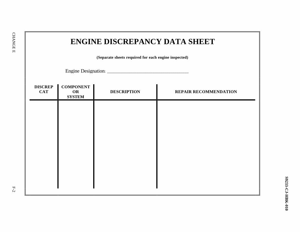
ENGINE DISCREPANCY DATA SHEET
(Separate sheets required for each engine inspected)
DISCREP
CAT COMPONENT
OR SYSTEM
DESCRIPTION
REPAIR RECOMMENDATION
Engine Designation: _________________________________________
S9233-CJ-H
BK
-010
F-2 C
HA
NG
E E

S9233-CJ-HBK-010
ALCO ENGINES
TOLERANCE MEASUREMENT DATA SHEET
USS _________________________ DATE _______________________ ENGINE NO. _________________
NOTE
All tolerance measurements are to be obtained in accordance with current PMS Maintenance Requirement Cards (MRCs) and
current printed instructions.
SPEC ACTUAL 1. Crankshaft measurements a. Crankshaft thrust readings _____ ________ b. Crankshaft deflection readings (TIR) _____ ________ ______________ q______________ _______________ ______________ Show direction of rotation.
2. Turbocharger measurements a. Crankshaft thrust readings _____ ________ b. Crankshaft deflection readings (TIR) _____ ________
G1-1

3. Pump timing measurements CYLINDER SAT UNSAT _________R ____ _______ _________R ____ _______ _________L ____ _______ _________L ____ _______ 4. Valve clearances CYLINDER SPEC ACTUAL _________R ____ _______ _________R ____ _______ _________L ____ _______ _________L ____ _______
NOTE
If there are any unusual wear patterns in the gear train, take the following measurements:
MIN MAX AVG
5. Water pump backlash measurement a. Jacket water _____ _____ _____ b. Raw water _____ _____ _____ 6. Lube oil pump backlash measurement _____ _____ _____ 7. Governor backlash measurement a. Bevel and pinion gears _____ _____ _____ b. Governor drive and camshaft gear _____ _____ _____
G1-2

S9233-CJ-HBK-010
MIN MAX AVG 8. Camshaft measurements. _____ _____ _____ a. Camshaft thrust _____ _____ _____ Right bank _____ _____ _____ Left bank _____ _____ _____ b. Camshaft backlash _____ _____ _____ Right bank _____ _____ _____ Left bank _____ _____ _____
G1-3
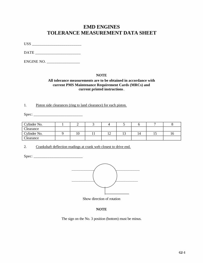
EMD ENGINES TOLERANCE MEASUREMENT DATA SHEET
USS _________________________ DATE _______________________ ENGINE NO. _________________
NOTE All tolerance measurements are to be obtained in accordance with
current PMS Maintenance Requirement Cards (MRCs) and current printed instructions .
1. Piston side clearances (ring to land clearance) for each piston. Spec: _________________________
Cylinder No. 1 2 3 4 5 6 7 8 Clearance Cylinder No. 9 10 11 12 13 14 15 16 Clearance 2. Crankshaft deflection readings at crank web closest to drive end. Spec: _________________________ ______________ q______________ _______________ ______________
Show direction of rotation
NOTE
The sign on the No. 3 position (bottom) must be minus.
G2-1

S9233-CJ-HBK-010
3. Crankshaft thrust reading. Spec: ___________________________ Actual Thrust: ____________________ 4. Cylinder head identification. _________________________________ ________________________________ _________________________________ ________________________________ _________________________________ ________________________________ _________________________________ ________________________________ _________________________________ ________________________________ _________________________________ ________________________________ _________________________________ ________________________________ _________________________________ ________________________________ 5. Exhaust valve clearances: Sat./Unsat ______________________________________ Cylinder No. 1 2 3 4 5 6 7 8 Sat./Unsat Cylinder No. 9 10 11 12 13 14 15 16 Sat./Unsat 6. Turbocharger thrust clearance (if applicable). Spec: ______________________________ Actual thrust: ____________________ 7. Turbocharger impeller-to-casing clearance (if applicable). Spec: ______________________________ Actual clearance: __________________ 8. Blower rotor-to-rear-end-plate clearance (if applicable). Spec: ______________________________ Actual clearance: __________________ 9. Blower rotor-to-front-end-plate clearance (if applicable). Spec: ______________________________ Actual clearance: __________________ 10. Blower rotor-to-rotor clearance (if applicable). Spec: ______________________________ Actual clearance: __________________ 11. Blower rotor-to-casing clearance (if applicable). Spec: ______________________________ Actual clearance:___________________ 12. Blower thrust. Spec: ______________________________ Actual clearance:___________________ 13. Timing gear backlash. Spec: ______________________________ Actual clearance:___________________
G2-2

S9233-CJ-HBK-010
FAIRBANKS MORSE ENGINES TOLERANCE MEASUREMENT DATA SHEET
USS _________________________ DATE _______________________ ENGINE NO. _________________
NOTE
All tolerance measurements are to be obtained in accordance with current PMS Maintenance Requirement Cards (MRCs) and
current printed instructions.
SPEC ACTUAL 1. Crankshaft measurements. a. Thrust bearings 1) Upper ______________ 2) Lower ______________ b. Deflections readings (TIR) ______________ q______________ _______________ ______________
Show direction of rotation
NOTE
The sign on the no. 3 position (bottom) must be minus.
G3-1

SPEC ACTUAL 2. Vertical drive measurements (if taken) a. Gear backlash 1) Lower ring gear to pinion _______ _______ 2) Upper ring gear to pinion _______ _______ b. Vertical drive shaft thrust (with coupling unbolted and spring pack removed). 1) Lower vertical drive ______ _______ 2) Upper vertical drive ______ ______ 3. Auxiliary drive gear assembly (if taken) FM 5 1/4 a. Crankshaft gear to auxiliary drive shaft gear. _____ _ _______ b. Auxiliary drive shaft-driven gear to bevel- driven gear ______ _______ c. Bevel-driven gear to fuel pump drive gear ______ _______ d. Governor drive pinion to gear ______ _______ e. Freshwater pump bevel gear to vertical drive gear ______ _______ 3A. Auxiliary drive gear assembly (if taken) FM 8 1/8 ______ _______ a. Crankshaft flexible drive gear to raw water pump gear ______ _______ b. Crankshaft flexible drive gear to jacket water pump gear ______ _______ c. Governor drive bevel gear to pinion gear ______ _______ d. Crankshaft drive gear to lubricating oil pump gear ______ _______ 4. Engine timing. a. Crankshaft lead (lower leading upper) ______ _______
G3-2
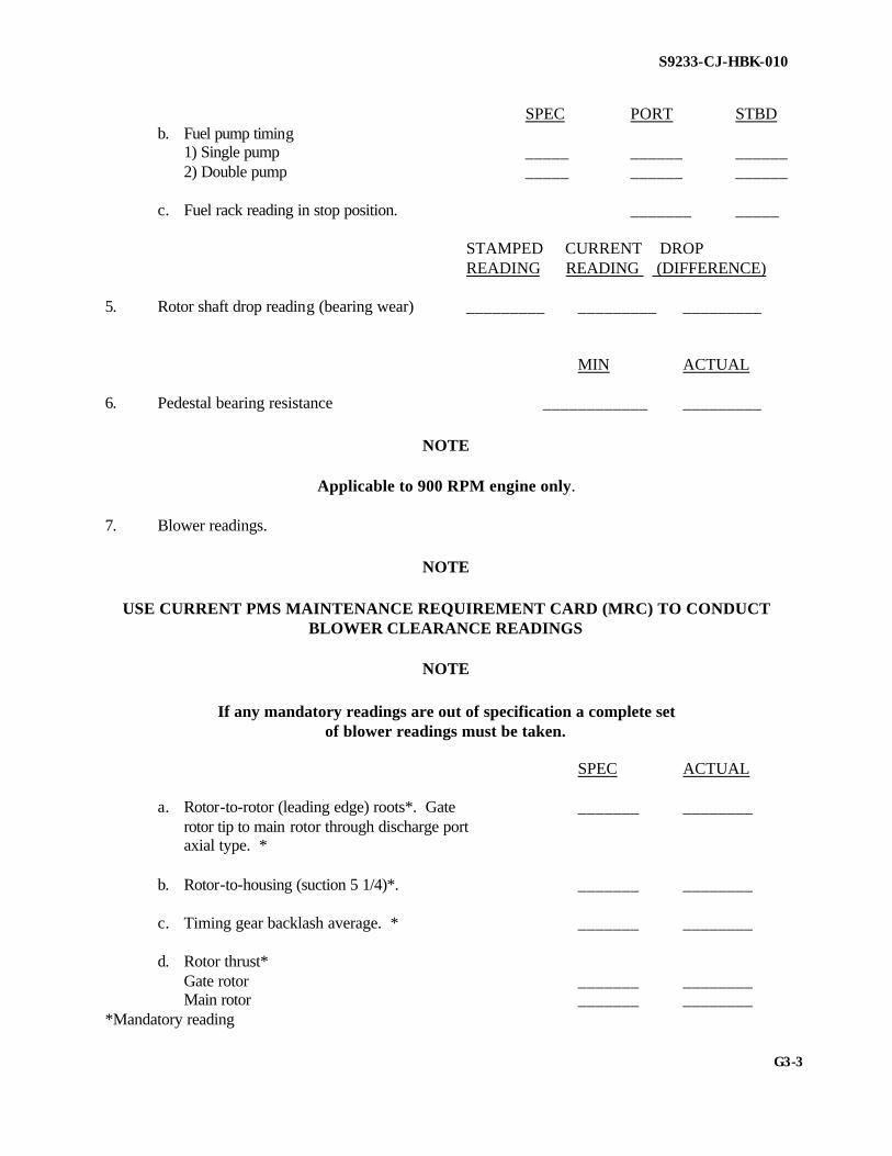
S9233-CJ-HBK-010
SPEC PORT STBD b. Fuel pump timing 1) Single pump _____ ______ ______ 2) Double pump _____ ______ ______ c. Fuel rack reading in stop position. _______ _____ STAMPED CURRENT DROP READING READING (DIFFERENCE) 5. Rotor shaft drop reading (bearing wear) _________ _________ _________ MIN ACTUAL 6. Pedestal bearing resistance ____________ _________
NOTE
Applicable to 900 RPM engine only.
7. Blower readings.
NOTE
USE CURRENT PMS MAINTENANCE REQUIREMENT CARD (MRC) TO CONDUCT BLOWER CLEARANCE READINGS
NOTE
If any mandatory readings are out of specification a complete set
of blower readings must be taken.
SPEC ACTUAL a. Rotor-to-rotor (leading edge) roots*. Gate _______ ________ rotor tip to main rotor through discharge port axial type. * b. Rotor-to-housing (suction 5 1/4)*. _______ ________ c. Timing gear backlash average. * _______ ________ d. Rotor thrust* Gate rotor _______ ________ Main rotor _______ ________ *Mandatory reading
G3-3

NOTE
If any unusual conditions were found during the course of the inspection on the above items, take and record the following
measurements.
SPEC DRIVE DRIVEN 8. Blower roots type a. Rotor to rotor leading ______________ _______ b. Rotor to rotor trailing ______________ _______ c. Rotor to housing suction ______________ _______ d. Rotor to housing discharge ______________ _______ e. Rotor to outer end plate ______________ _______ f. Rotor to inner end plate ______________ _______ g. Thrust (end movement of rotor) ______________ _______ GATE ROTOR TIP A B C D READING PRESENT READINGS DATE ___________________________ GATE ROTOR TIP A B C D READING PREVIOUS READINGS DATE __________________________ GATE ROTOR TIP TO MAIN ROTOR BODY, PRESENT AND PREVIOUS READINGS
TABLE 1
G3-4

S9233-CJ-HBK-010
COLT-PIELSTICK ENGINES TOLERANCE MEASUREMENT DATA SHEET
USS _________________________ DATE _______________________ ENGINE NO. _________________
NOTE
All tolerance measurements are to be obtained in accordance with current PMS Maintenance Requirement Cards (MRCs) and current
printed instructions.
SPEC ACTUAL 1. Crankshaft. a. Thrust (PMS) _______ _______ b. Deflection readings. (If readings taken within three months before engine inspection are within specification, the data may be used to satisfy the requirements of this step.) Document measurements on record sheet (PMS). _______ _______ 2. Camshaft Thrust (PMS) _______ _______ a. Right bank _______ _______ b. Left bank _______ _______ 3. Seawater Pump. a. Pump Drive Thrust _______ _______ b. Suction Side Wear Ring Diametrical Clearance ______ ________
G4-1

4. Web Deflections and Bearing Presses MMR No. 2 MMR No. 1 Port Engines Stbd Engines CCW Rotation CW Rotation
View from View from Drive End Drive End
WEB MOTION (mm)/ BEARING PRESSES
BRG FREE
END DRIVE
END 1 ______
2
3
4
5
6
7
8
9 ______
G4-2

S9233-CJ-HBK-010
WEB DEFLECTIONS
G4-3

CHART FOR CRANKSHAFT WEB DEFLECTION CALCULATIONS AND RECORDS
ENGINE I.D. ______________ SER NO. ________ DATE ________________ BY ____________________________
MAIN BEARING NO. 1 2 3 4 5 6 7 8 9 WEB MOTION (mm) = bc: BEARING CLEARANCE =
C: LARGER VALUE of bc =
THROW POSITION CYL. NO.
1 1&9
2 2&10
3 3&11
4 4&12
5 5&13
6 6&14
7 7&15
8 8&16
ml mm m5 mm (m1+m5)/2 mm m3 mm dv=m3-(m1+m5)/2 mm d – DIFFERENCE CORRECTED DEFLECTION dc = dv + c/2
d – DIFFERENCE m4 m2 dh = m2 – m4 d – DIFFERENCE
MAXIMUM PERMISSIBLE DIFFERENCE BETWEEN ADJACENT CRANKWEBS: VERTICAL #1 & 2 NEW 0.06mm/IN SERVICE 0.06 mm HORIZONTAL ALL WEBS NEW LESS THAN 0.03 mm DEFLECTION #2 THRU #8 NEW 0.03mm/IN SERVICE 0.06 mm DEFLECTION ALL WEBS IN SERVICE LESS THAN 0.06 mm LO SUMP TEMP _____°F JACKET WATER TEMP _____°F AMBIENT TEMP ____° F
G4-4

S9233-CJ-HBK-010
DDA 16V 149 DIESEL ENGINES
TOLERANCE MEASUREMENT DATA SHEETS
USS _________________________ DATE _______________________ ENGINE NO. _________________
NOTE All tolerance measurements are to be obtained in accordance with
current PMS Maintenance Requirement Cards (MRCs) and current printed instructions.
SPEC ACTUAL 1. Crankshaft measurements. _______ _______ Crankshaft thrust readings _______ _______ 2. Lubricating oil pump drive gear backlash. _______ _______ 3. Turbocharger measurements. a. Port fwd – Axial _______ _______ b. Port aft – Axial _______ _______ c. Stbd fwd – Axial _______ _______ b. Stbd aft – Axial _______ _______ 4. Camshaft thrust. a. Right bank _______ _______ b. Left bank _______ _______ 5. Backlash. a. Lube oil pump/drive gear _______ _______ b. JW pump gear _______ _______
G5-1

6. Blowers. a. Measure blower(s) clearance.
NOTE
Refer to current PMS MRC for specifications.
Forward blower SPEC LOCATION SYMBOL MIN MAX ACTUAL Rotor to end plate (gear end) A ____ ____ ________ Rotor to end plate B ____ ____ ________ Leading edge of R.H. rotor to trailing edge of L.H. rotor C ____ ____ ________ Trailing edge of R.H. rotor to leading edge of L.H. rotor CC ____ ____ ________ Rotors to case, inlet side D ____ ____ ________ Aft blower SPEC LOCATION SYMBOL MIN MAX ACTUAL Rotor to end plate (gear end) A ____ ____ ________ Rotor to end plate B ____ ____ ________ Leading edge of R.H. rotor to trailing edge of L.H. rotor C ____ ____ ________ Trailing edge of R.H. rotor to leading edge of L.H. rotor CC ____ ____ ________ Rotors to case, inlet side D ____ ____ ________
G5-2

S9233-CJ-HBK-010
SMALL HIGH-SPEED ENGINES
TOLERANCE MEASUREMENT DATA SHEETS
USS _________________________ DATE _______________________ ENGINE NO. _________________
NOTE All tolerance measurements are to be obtained in accordance with
current PMS Maintenance Requirement Cards (MRCs) and current printed instructions.
SPEC MIN MAX ACT 1. Crankshaft thrust. _____ _____ ______ 2. Blower readings (in accordance with _____ _____ ______ applicable PMS) 3. Turbocharger measurements (if applicable) Port-Axial _____ _____ ______ Stbd-Axial _____ _____ ______
G6-1

S9233-CJ-HBK-010
G8-2
GENERIC MEDIUM-SPEED DIESEL ENGINE TOLERANCE MEASUREMENT DATA SHEET
USS _________________________ DATE _______________________ ENGINE NO. _________________
NOTE
All tolerance measurements are to be obtained in accordance with current PMS Maintenance Requirement Cards (MRCs) and current
printed instructions.
SPEC ACT 1. Crankshaft measurements. ______ _____ a. Crankshaft thrust readings ______ _____ b. Crankshaft deflection readings (TIR) ______ _____
NOTE:
The sign on the No. 3 position (bottom) must be a minus. ______________ q______________ _______________ ______________
Show direction of rotation
G7-1
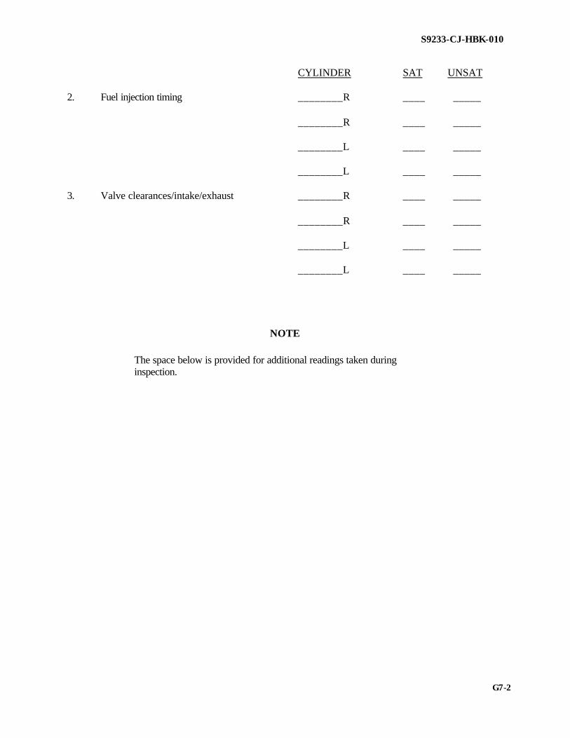
S9233-CJ-HBK-010
CYLINDER SAT UNSAT 2. Fuel injection timing ________R ____ _____ ________R ____ _____ ________L ____ _____ ________L ____ _____ 3. Valve clearances/intake/exhaust ________R ____ _____ ________R ____ _____ ________L ____ _____ ________L ____ _____
NOTE
The space below is provided for additional readings taken during inspection.
G7-2

S9233-CJ-HBK-010
CATERPILLAR D399, D398, D379, D353 ENGINES TOLERANCE MEASUREMENT DATA SHEET
USS _________________________ DATE _______________________ ENGINE NO. _________________
NOTE
All tolerance measurements are to be obtained in accordance with current PMS Maintenance Requirement Cards (MRCs) and
current printed instructions.
SPEC MIN MAX ACT 1. Crankshaft thrust. _____ _____ ______ 2. Turbocharger measurements (if applicable) Port-Axial _____ _____ ______ Stbd-Axial _____ _____ ______ 3. Deflection readings (D399, D398) ______________ q______________ _______________ ______________
Show direction of rotation.
G8-1

S9233-CJ-HBK-010
WAUKESHA ENGINES TOLERANCE MEASUREMENT DATA SHEET
USS _________________________ DATE _______________________ ENGINE NO. _________________
NOTE
All tolerance measurements are to be obtained in accordance with current PMS Maintenance Requirement Cards (MRCs) and current
printed instructions. .
SPEC MIN MAX ACT 1. Crankshaft thrust. _____ _____ ______ 2. Turbocharger measurements (if applicable). Port-Axial _____ _____ ______ Stbd-Axial _____ _____ ______ 3. Lube oil pump backlash. _____ _____ ______ 4. Collision chock settings. _____ _____ ______ _____ _____ ______ _____ _____ ______ _____ _____ ______ _____ _____ ______ 5. Fuel oil pump backlash. _____ _____ ______ 6. Generator oil scavenging pump backlash. _____ _____ ______
G9-1

S9233-CJ-HBK-010
CHANGE D
ISOTTA FRASCHINI (IF) DIESEL ENGINES TOLERANCE MEASUREMENT DATA SHEETS
USS _________________________ DATE _______________________ ENGINE NO. _________________
NOTE
All tolerance measurements are to be obtained in accordance with current PMS Maintenance Requirement Cards (MRCs) and current
printed instructions.
SPEC ACTUAL 1. Crankshaft thrust. 0.____"/0._____" 0.____" 2. Turbocharger measurements (if applicable). Port-Axial 0.____"/0._____" 0.____" Stbd-Axial 0.____"/0._____" 0.____" 3. Lube oil pump backlash. 0.____"/0._____" 0.____" (if applicable) 4. Valve lash settings. 0.____"/0._____" 0.____" 0.____"/0._____" 0.____" 0.____"/0._____" 0.____" 0.____"/0._____" 0.____" 0.____"/0._____" 0.____" 0.____"/0._____" 0.____" 0.____"/0._____" 0.____" 5. Camshaft endplay. 0.____"/0._____" 0.____" (if applicable) 0.____"/0._____" 0.____" 0.____"/0._____" 0.____"
G10-1

S9233-CJ-HBK-010
CHANGE D
PAXMAN 16RP200M ENGINE MEASUREMENT TOLERANCE MEASUREMENT DATA SHEETS
USS _________________________ DATE _______________________ ENGINE NO. _________________
NOTE
All tolerance measurements are to be obtained in accordance with current PMS Maintenance Requirement Cards (MRCs) and current
printed instructions.
1. Deflection readings. SPEC ACT ______________ q______________ _______________ ______________
DRIVE END
NOTE
Show direction of engine rotation.
G11-1

S9233-CJ-HBK-010
CHANGE D
2. Inducer to blower inlet casing clearance. SPEC ACT
NOTE
Take measurement in 90 interval as shown above. 3. Valve Clearances.
NOTE
Refer to Paxman Technical Manuals S9233-E1-MMC-010 and S9233-E1-MMC-020
4. Engine Mount Rebound. SPEC ACTUAL DEA ______ _______ FEA ______ _______ FEB ______ _______ DEB ______ _______ 5. Engine distance from alignment arm to sole plate. SPEC ACTUAL DEA ______ _______ FEA ______ _______ FEB ______ _______ DEB ______ _______
G11-2

S9233-CJ-HBK-010
CHANGE D
CATERPILLAR 3600 SERIES DIESEL ENGINES TOLERANCE MEASUREMENT DATA SHEETS
USS _______________________________________(____________) ENGINE NO. _________________
NOTE
All tolerance measurements are to be obtained in accordance with current PMS Maintenance Requirement Cards (MRCs) and
current printed instructions.
MIN/MAX ACTUAL 1. Crankshaft thrust. 0.____"/0._____" 0.____" 2. Turbocharger measurements (if applicable). Port-Axial 0.____"/0._____" 0.____" Port-Thrust 0.____"/0._____" 0.____" Stbd-Axial 0.____"/0._____" 0.____" Stbd-Thrust 0.____"/0._____" 0.____" 3. Crankshaft deflection readings 0.____"/0._____" 0.____" (D398, D399 and 3608)
0.____" 0.____"
CCW
0.____" 0.____"
0.____" 4. Crankshaft/camshaft timing. Sat./Unsat. ______ 5. Governor linkage adjustment. Sat./Unsat. ______ 6. Governor fuel rack setting. Sat./Unsat. ______
G12-1

S9233-CJ-HBK-010
TOLERANCE MEASUREMENT DATA SHEET MTU MODEL 396TE94 DIESEL ENGINE
MEASUREMENT DATA SHEET Craft Hull No.: Engine No.:
NOTE:
All tolerance measurements are to be obtained in accordance with current PMS Maintenance Requirement Cards (MRCs) requirements
and current printed instructions.
1. Valve Clearances.
NOTE:
Engine is viewed from the Power Take Off (PTO) end. (** As required). A BANK 1 2 3 4 5 6 Intake Exhaust B BANK 1 2 3 4 5 6 Intake Exhaust 2. Measure turbocharger thrust. Turbo A__________** (As required) Turbo B__________** (As required) 3. Measure shut down flap proximity switch clearance. (MTU B84 620) __________ 5.5 to 4.5 MM
G13-1

S9233-CJ-HBK-010
ALCO ENGINES OPERATIONAL TEST DATA SHEET
Ship name: __________________________ Engine rpm: ________________________ Engine No.: _________________________ KW: ______________________________ Date: _______________________________ Amps: _____________________________ Hrs. since overhaul: ___________________ Volts: _____________________________ Hrs. since last trend: ___________________ Governor power reading: ______________ Sea state (MPE only): __________________ Control air psi: ______________________ Ships draft (MPE only): ________________ Shaft rpm (MPE only): ________________ Ft/% of pitch (MPE only): _______________ Exhaust Temperature
Cylinder No. 1L 2L 3L 4L 5L 6L 7L 8L
Ex. Temp* Fi. Press* Com. Press* Rack Pos*
Cylinder No. 1R 2R 3R 4R 5R 6R 7R 8R
Ex. Temp* Fi. Press* Com. Press* Rack Pos* * Record at the same time. Pressures: Temperatures Crankcase vacuum: ___________________ J.W. to engine: _________________ Fuel header press: ____________________ J.W. from engine: _______________ L.O. pump disch: ____________________ L.O. to engine: _________________ J.W. pump disch: ____________________ L.O. from engine: _______________ S.W. pump disch: ____________________ S.W. in: ______________________ Generator brg—fwd: __________________ S.W. overboard:________________ Generator brg—aft: ___________________ Generator brg—fwd: ____________ L.O. strainer DP: _____________________ Generator brg—aft: _____________ L.O. filter DP: _______________________ Air box press/turbo: __________________ Overspeed Trip Setting: __________
H1-1

S9233-CJ-HBK-010
HIGH LOW AVERAGE Cylinder firing pressures ______ ______ __________ Cylinder compression pressures ______ ______ __________ Cylinder exhaust temperatures ______ ______ __________ Left bank temp. average: ______ ______ __________ Right bank exhaust temp average: ______ ______ __________ Right and left bank difference: _ _____ ______ __________
H1-2

S9233-CJ-HBK-010
EMD ENGINES OPERATIONAL TEST
DATA SHEET
Ship name: __________________________ Date: ______________________________ Engine No: __________________________ Hrs. since overhaul: ___________________ Hrs. since last trend: __________________ Main propulsion diesel: SSD/EDG: Engine/shaft RPM: __________________ Engine RPM: _____________________ Pitch: _____________________________ KW load: _________________________ Ship draft: _________________________ Amperage: ________________________ Sea state: __________________________ Voltage: __________________________ Governor power piston position _________ Control air pressure: __________________ Exhaust Temperature
Cylinder No. 1 2 3 4 5 6 7 8
Ex. Temp Fi. Press Cylinder No. 9 10 11 12 13 14 15 16
Ex. Temp Fi. Press HIGH LOW AVERAGE Cylinder exhaust temp: ______ ______ __________ Cylinder firing press: ______ ______ __________
NOTE
Record cylinder exhaust temperatures at the same time you take the firing pressures.
H2-1
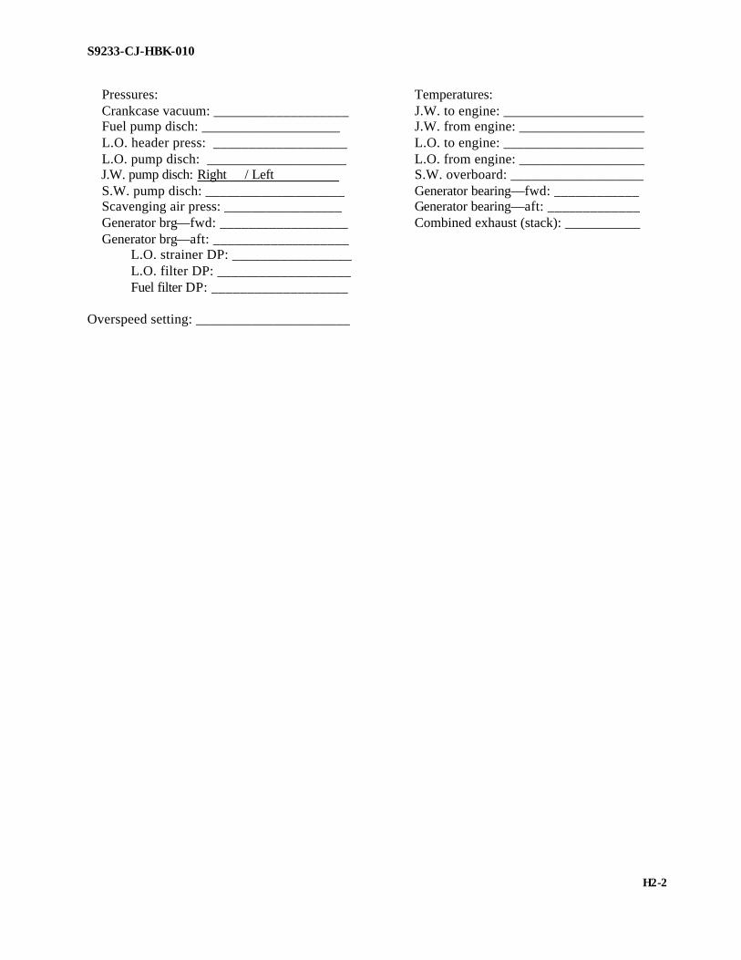
S9233-CJ-HBK-010
Pressures: Temperatures: Crankcase vacuum: ___________________ J.W. to engine: ____________________ Fuel pump disch: ____________________ J.W. from engine: __________________ L.O. header press: ___________________ L.O. to engine: ____________________ L.O. pump disch: ____________________ L.O. from engine: __________________ J.W. pump disch: Right / Left S.W. overboard: ___________________ S.W. pump disch: ____________________ Generator bearing—fwd: ____________ Scavenging air press: _________________ Generator bearing—aft: _____________ Generator brg—fwd: __________________ Combined exhaust (stack): ___________ Generator brg—aft: ___________________ L.O. strainer DP: _________________ L.O. filter DP: ___________________ Fuel filter DP: ___________________ Overspeed setting: ______________________
H2-2

S9233-CJ-HBK-010
FAIRBANKS MORSE ENGINES OPERATIONAL TEST DATA SHEET
Ship name: __________________________ Engine RPM: ________________________ Date: _______________________________ KW: ______________________________ Engine No.: _________________________ Amps: _____________________________ Hrs. since overhaul: ___________________ Volts: _____________________________ Hrs. since last trend: ___________________ Governor power indicator reading: _______ Sea state (MPE only): __________________ Control air PSI: ______________________ Ships draft (MPE only): ________________ Shaft torque (MPE only): ______________ Ft/% of pitch (MPE only): ______________ Shaft RPM (MPE only): ________________
Cylinder No. 1 2 3 4 5 6
Ex. Temp* Fi. Press* Com. Press* Rack Pos* Inbd Outbd Cylinder No. 7 8 9 10 11 12
Ex. Temp* Fi. Press* Com. Press* Rack Pos* Inbd Outbd * Record at the same time. HIGH LOW AVERAGE Cylinder exhaust temperature _ _____ ______ __________ Cylinder compression pressure ______ ______ __________ Cylinder firing pressure ______ ______ __________
H3-1

S9233-CJ-HBK-010
Pressures: Temperatures Fuel oil header press: __________________ J.W. temp to engine:________________ Fuel oil pump disch press: ______________ J.W. temp from engine: _____________ Lube oil header press: _________________ Lube oil temp to engine: ____________ S.W. pump disch/diff press: _____________ Lube oil temp from engine: __________ Crankcase vacuum (H2O): ______________ S.W. injection temp: _______________ Lube oil filter DP: ____________________ S.W. overboard temp:_______________ Lube oil strainer DP: __________________ Scavenging air press: __________________ Turbocharger disch. press: ______________ J.W. pump disch. press: ________________ Exh. back press: ______________________ Blower delta T: _______________________ Overspeed trip setting: ____________________
H3-2

S9233-CJ-HBK-010
CHANGE F
COLT-PIELSTICK ENGINES OPERATIONAL TEST
DATA SHEET
Ship name: __________________________ Date: ______________________________ Hrs since last trend: ___________________ Control air pressure: __________________ Engine No.: __________________________ Start air pressure to eng: _______________ Hrs. since ovhl: ______________________ Alarms and Safety Checks: Overspeed setting: ____________________rpm
Low Lube Oil Pressure Standby Pump Start Alarm Engine Shutdown Low Speed=175-290 rpm Med Speed=291-370 rpm High Speed=371-520 rpm
NOTE
Operate propulsion engines at 100 percent rated load and speed: 525,000 lb-ft and 520 rpm.
Cylinder No. 1 2 3 4 5 6 7 8
Ex. Temp* Fir. Press Rack Pos* Cylinder No. 9 10 11 12 13 14 15 16
Ex. Temp* Fir. Press Rack Pos* *Note : Take temperature readings simultaneously with firing pressures. Readings should be taken at EOSC. Fuel rack position readings must be taken at each injection pump. Note: Check the fuel leak off sight glasses, the maximum leak off is 5 drops per minute.
H4-1

S9233-CJ-HBK-010
MAX. HIGH LOW AVERAGE DIFF.
Cylinder firing pressures ______ ______ __________ ________ Cylinder exhaust temperatures ______ ______ __________ ________ Fuel rack position ______ ______ __________ ________ Pre-turbo exh temp LB/RB ______/_______ Post-turbo exh temp LB/RB _______/_____ Governor output lever quadrant position: ___________________________________________ Engine rpm: ________________________ Shaft rpm: _________________________ Pitch %: ___________________________ Shaft torque lb/ft: ___________________ Ship draft: _________________________ Sea state: __________________________ Pressures: Temperatures: Lube oil disch press: _______________ Lube oil temp to engine: ____________ Lube oil press to engine: ____________ Lube oil temp to cooler: ____________ J.W. pump suct press: ______________ J.W. water temp to engine: __________ J.W. pump disch press: _____________ J.W. water temp from engine: ________ J.W. press to engine: _______________ Injector clg wtr outlet temp: __________ S.W. pump suct press: ______________ Rocker lube oil temp: _______________ S.W. pump disch press: _____________ S.W. injection temp: _______________ Lube oil filter DP: ______/___________ S.W. inlet temp to intercooler: Lube oil strainer DP: _______________ Left bank/right bank:______/_______ Rocker lube oil press: ______________ S.W. outlet temp from intercooler: Turbo disch press: _________________ Left bank/right bank: _____/_______ Left bank/right bank: _____________ Intake air manifold temp: Rocker lube oil strainer DP: __________ Left bank/right bank: _____/_______ Fuel pump suct press: ______________ Fuel pump disch press: ______________ Fuel filter DP: _____________________ Fuel press to engine: ________________ Crankcase vacuum (H2O) ____________
H4-2
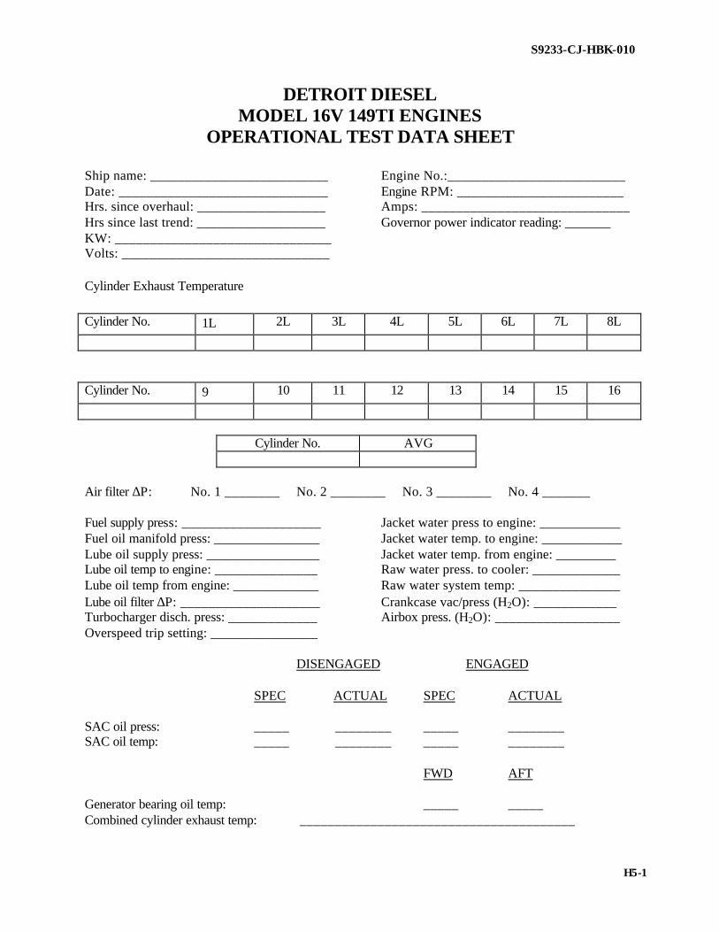
S9233-CJ-HBK-010
DETROIT DIESEL MODEL 16V 149TI ENGINES
OPERATIONAL TEST DATA SHEET
Ship name: __________________________ Engine No.:__________________________ Date: ______________________________ Engine RPM: ________________________ Hrs. since overhaul: ___________________ Amps: ______________________________ Hrs since last trend: ___________________ Governor power indicator reading: _______ KW: _______________________________ Volts: ______________________________ Cylinder Exhaust Temperature
Cylinder No. 1L 2L 3L 4L 5L 6L 7L 8L
Cylinder No. 9 10 11 12 13 14 15 16
Cylinder No. AVG
Air filter ∆P: No. 1 ________ No. 2 ________ No. 3 ________ No. 4 _______ Fuel supply press: ____________________ Jacket water press to engine: ____________ Fuel oil manifold press: ________________ Jacket water temp. to engine: ____________ Lube oil supply press: _________________ Jacket water temp. from engine: _________ Lube oil temp to engine: _______________ Raw water press. to cooler: _____________ Lube oil temp from engine: _____________ Raw water system temp: _______________ Lube oil filter ∆P: ____________________ Crankcase vac/press (H2O): ____________ Turbocharger disch. press: _____________ Airbox press. (H2O): __________________ Overspeed trip setting: ________________ DISENGAGED ENGAGED SPEC ACTUAL SPEC ACTUAL SAC oil press: _____ ________ _____ ________ SAC oil temp: _____ ________ _____ ________ FWD AFT Generator bearing oil temp: _____ _____ Combined cylinder exhaust temp: _______________________________________
H5-1

S9233-CJ-HBK-010
Operation of electrostatic precipitators: SMOKE/OIL FOG/MIST SAT UNSAT Operation of air flapper shutdown: At CCS ____ _______ Local ____ _______
H5-2

S9233-CJ-HBK-010
SMALL HIGH-SPEED ENGINE OPERATIONAL TEST DATA SHEET
Ship name: __________________________ Engine rpm:_________________________ Date: ______________________________ KW: _______________________________ Engine No.: _________________________ Amps: ______________________________ Hrs. since overhaul: ___________________ Volts: ______________________________ Hrs since last trend: ___________________ Governor power indicator reading: _______
Start air PSI:_________________________ Cylinder Exhaust Temperature
Cylinder No. 1L 2L 3L 4L 5L 6L 7L 8L
Exhaust Temp
Cylinder No. 9 10 11 12 13 14 15 16
Exhaust Temp
Cylinder No. AVG Exhaust Temp
Fuel oil press to filter: _________________ Jacket water press to engine: ____________ Fuel oil press to engine: _______________ Jacket water temp. to engine: ____________ Lube oil pump disch. press: _____________ Jacket water temp. from engine: _________ Lube oil press at engine: _______________ Raw water press to cooler: _____________ Lube oil temp to engine: _______________ Raw water injection temp: ______________ Lube oil temp from engine: _____________ Raw water overboard temp: _____________ Lube oil filter DP: ____________________ Crankcase pressure (H2O): ______________ Lube oil strainer DP: __________________ Crankcase vacuum (H2O): ______________ Gen lube oil alarm: ___________________ Air box press:________________________ Overspeed RPM: _____________________ Lube oil alarm: _______________________ Generator bearing oil press: ____________ ______________ Generator bearing oil temp: ____________ ______________ Right bank exhaust temp. average: __________________________ Left bank exhaust temp. average: ___________________________ Left and right bank exhaust temp. difference: _________________________ Overspeed trip setting: __________________________ Low lube oil alarm: ____________________________
H6-1

S9233-CJ-HBK-010
GENERIC MEDIUM-SPEED DIESEL ENGINE
OPERATIONAL TEST DATA SHEET
Ship name: __________________________ Engine rpm:_________________________ Date: ______________________________ KW: _______________________________ Engine No.: _________________________ Amps: ______________________________ Engine Model: _______________________ Volts: ______________________________ Hrs. since overhaul: ___________________ Governor power indicator reading: _______ Hrs since last trend: ___________________ Control air PSI:_______________________ Sea State (MPE only): _________________ Shaft torque (MPE only): _______________ Ships draft (MPE only): ________________ Ft./% of pitch (MPE only): ______________ Shaft rpm (MPE only): _________________
Cylinder No. 1 2 3 4 5 6 7 8
Ex. Temp*
Fi. Press*
Com press
Rack Pos*
Inbd
Outbd
Cylinder No. 9 10 11 12 13 14 15 16
Ex. Temp*
Fi. Press*
Rack Pos*
Inbd
Outbd * Record at the same time.
H7-1

S9233-CJ-HBK-010
Pressures Temperatures
Fuel oil header press: ___________________ J.W. temp to engine: __________________ Lube oil pump disch. press: ______________ J.W. temp from engine: ________________ Engine lube oil press: ___________________ Lube oil temp to engine:________________ S.W. pump disch/diff press: ______________ Lube oil temp from engine: _____________ Crankcase vacuum (H2O): _______________ S.W. injection temp: __________________ Lube oil filter ∆P: ______________________ S.W. overboard temp: _________________ Lube oil strainer ∆P: ____________________ Scavenging air press: ___________________ Turbocharger disch press: _______________ J.W. pump disch press: Right ______ Left ________ Exh back press: _______________________ Blower ∆T: __________________________ Overspeed trip setting: __________________ HIGH LOW AVERAGE Cylinder exhaust temp: _____ _____ __________ Cylinder compression press: _____ _____ __________ Cylinder firing press: _____ _____ __________
H7-2

S9233-CJ-HBK-010
CATERPILLAR D399, D398, D379, D353 ENGINES
OPERATIONAL TEST DATA SHEET
Ship name: __________________________ Engine rpm:_________________________ Date: ______________________________ kW: _______________________________ Engine No.: _________________________ Amps: ______________________________ Hrs. since overhaul: ___________________ Volts _______________________________ Hrs since last trend: ___________________ Sea State (MPE only): _________________ Ships draft (MPE only): ________________ Ft./% of pitch (MPE only): ______________ Shaft rpm (MPE only): ________________ Shaft torque (MPE only): _______________ Cylinder Exhaust Temperature
Cylinder No. 1L 2L 3L 4L 5L 6L 7L 8L
Cylinder No. 1R 2R 3R 4R 5R 6R 7R 8R
Cylinder No. AVG
Fuel oil press to filter: _________________ Jacket water press to engine: ____________ Fuel oil press to engine: _______________ Jacket water temp. to engine: ____________ Lube oil pump disch press: _____________ Jacket water temp. from engine __________ Lube oil press at engine: _______________ Raw water press. to cooler: _____________ Lube oil temp to engine: _______________ Raw water injection temp: ______________ Lube oil temp from engine: _____________ Raw water overboard temp: _____________ Lube oil filter DP: ____________________ Crankcase pressure (H2O): ______________ Lube oil strainer DP: __________________ Crankcase vacuum (H2O): ______________ Low lube oil alarm: ___________________ Turbocharger disch. press:______________ FWD AFT Generator bearing oil press: ____________ ______________ Generator bearing oil temp: ____________ ______________
H8-1

S9233-CJ-HBK-010
HIGH LOW AVERAGE Cylinder exhaust temp: _____ _____ __________ Left bank exhaust temp. average: _____ _____ __________ Left and right bank exhaust temp. difference: _________________________ Overspeed trip setting: _____________________ Low lube oil alarm: ________________________
H8-2

S9233-CJ-HBK-010
WAUKESHA DIESEL ENGINES OPERATIONAL TEST
DATA SHEET
Ship name: __________________________ Engine rpm:_________________________ Date: ______________________________ KW: _______________________________ Engine No.: _________________________ Amps: ______________________________ Hrs. since overhaul: ___________________ Volts: ______________________________ Hrs since last trend: ___________________ Governor power indicator reading: _______ Date of last trend: ____________________ Control air PSI:_______________________ Sea State (MPE only): _________________ Ships draft (MPE only): ________________ Ft./% of pitch (MPE only): ______________ Shaft rpm (MPE only): ________________ Shaft torque (MPE only): _______________
Cylinder Exhaust Temperature
Cylinder No. 1L 2L 3L 4L 5L 6L
Cylinder No. 1R 2R 3R 4R 5R 6R
Engine rpm: ________________________ Fuel oil supply press: __________________ Freshwater Temp: ____________________ Preturbo exh temp (RB): _______________ L.O. pump press: _____________________ Preturbo exh temp (LB): _______________ L.O. Filter DP: _______________________ Fuel Rack Position: ___________________ Seawater pump press: _________________ Stack temp: __________________________ Freshwater pump press: ________________ Seawater temp: _______________________ Air manif. press (LB): _________________ Pitch (% ft): _________________________ Air manif. press (RB): _________________ Engine rotation: ______________________ Lube oil gallery press: _________________ Output power (kW): ___________________ Lube oil sump temp: __________________ Output voltage: _______________________ Output freq: _________________________ Forward bearing temp: _________________ Aft bearing temp: _____________________ Overspeed trip setting: _________________ Low lube oil alarm: ____________________
H9-1

S9233-CJ-HBK-010
CHANGE D
ISOTTA FRASCHINI (IF) OPERATIONAL TREND DATA SHEET
USS ______________________________________ (____ ____) ENGINE RPM: ________________________________ DATE: _______________________________ Cycles: _________________ Engine Nr.: ____________________________ Kilowatts: _____________________________
Hrs. since overhaul: _____________________Amperes: _____________________ Hrs. since last trend: ____________________ Volts: ________________________ Sea state (MPE only): ___________________ Governor power indicator reading: _______ Ships draft (MPE only): _________________ Control air psi: _______________________ FT% of pitch (MPE only): _______________ Shaft RPM (MPE only): _______________
Cylinder Exhaust Temperatures
1L 2L 3L 4L 1R 2R 3R 4R Fuel oil press. to filter: ___________________ Jacket water temp to engine: ____________ Fuel oil press. to engine: __________________ Jacket water temp. from engine: _________ Fuel oil filter DP: _______________________ Salt water injection temp: ______________ Lube oil pump disch. press.: _______________ Salt water overboard temp: _____________ Lube oil press. to engine: _________________ Lube oil temp. from engine: _____________ Turbocharger lube oil press.: _______________ Lube oil temp. to engine: _______________ Lube oil filter DP: _______________________ Lube oil strainer DP: _____________________ Jacket water press. to engine: ______________ Salt water press. to cooler: _________________ Crankcase vacuum (H2O): _________________ Scavenging air press.: _____________________ Air filter DP: ____________________________ Condition of: Gauges Thermometers Pyrometers Meters _______ ___________________ ______ Overspeed Device: Specification Actual _____-_____ RPM’s ______ RPM’s Lube Oil Alarms: Specification Actual _____ PSI ______ PSI Remote shutdown Device: Operative ________
H10-1
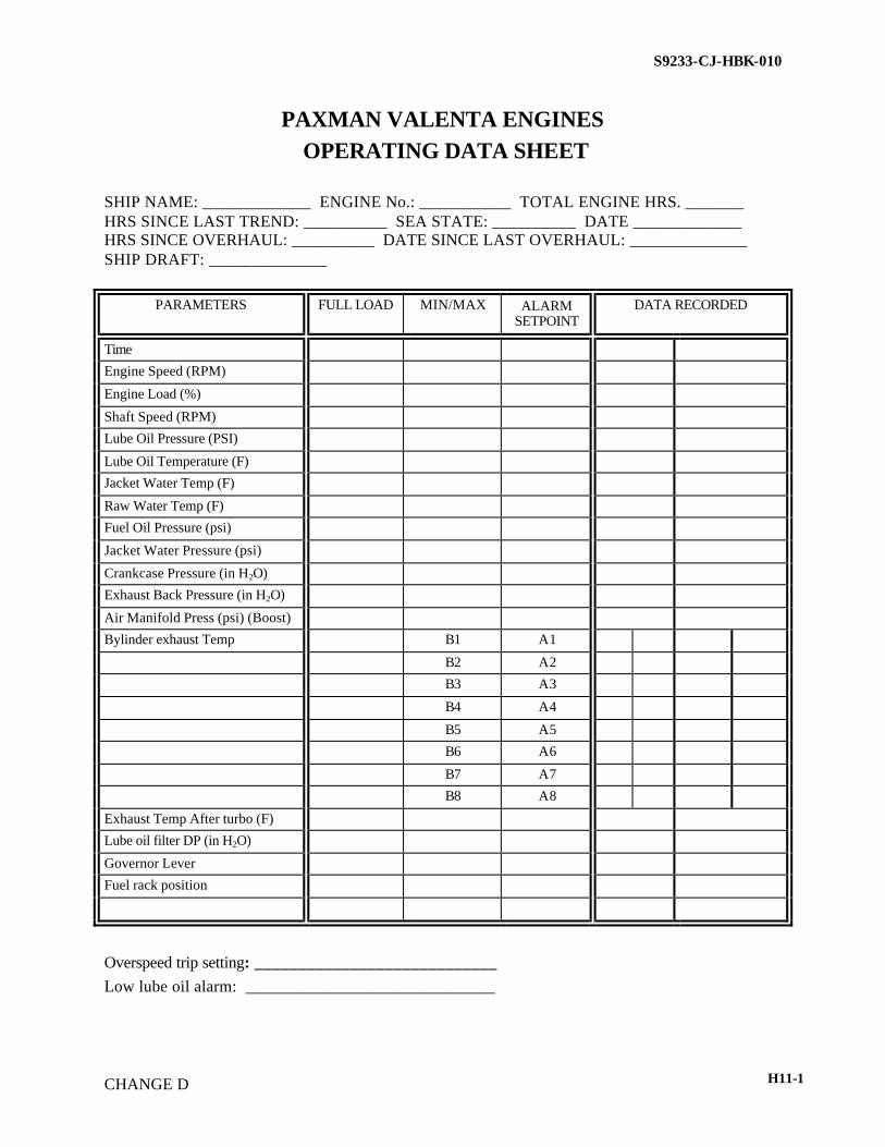
S9233-CJ-HBK-010
CHANGE D
PAXMAN VALENTA ENGINES OPERATING DATA SHEET
SHIP NAME: _____________ ENGINE No.: ___________ TOTAL ENGINE HRS. _______ HRS SINCE LAST TREND: __________ SEA STATE: __________ DATE _____________ HRS SINCE OVERHAUL: __________ DATE SINCE LAST OVERHAUL: ______________ SHIP DRAFT: ______________
PARAMETERS FULL LOAD MIN/MAX ALARM SETPOINT
DATA RECORDED
Time
Engine Speed (RPM)
Engine Load (%)
Shaft Speed (RPM)
Lube Oil Pressure (PSI)
Lube Oil Temperature (F)
Jacket Water Temp (F)
Raw Water Temp (F)
Fuel Oil Pressure (psi)
Jacket Water Pressure (psi)
Crankcase Pressure (in H2O)
Exhaust Back Pressure (in H2O)
Air Manifold Press (psi) (Boost)
Bylinder exhaust Temp B1 A1
B2 A2
B3 A3
B4 A4
B5 A5
B6 A6
B7 A7
B8 A8
Exhaust Temp After turbo (F)
Lube oil filter DP (in H2O)
Governor Lever
Fuel rack position
Overspeed trip setting: ____________________________ Low lube oil alarm: ______________________________
H11-1

S9233-CJ-HBK-010
CHANGE D
PAXMAN VALENTA OPERATING CHECKS WORKSHEET
1. Check high-pressure duoline sheathed fuel injection pipe for leakage.
Comments: _____________________________________________ 2. Inspect all external fuel lines, unions, and coupling fuel leaks.
Comments: _____________________________________________ 3. Check for leaks at exhaust stack, exhaust manifold gaskets, expansion bellows and
turbocharger exhaust inlet. Comments: _____________________________________________
4. Inspect for air leaks at intake manifold to heads and joints at air delivery casing to manifolds.
Comments: _____________________________________________ 5. Inspect complete external lube oil piping for leaks.
Comments: _____________________________________________
6. Inspect jacket water and raw water pump telltale orifice for leakage or blockage. (Leakage from telltale lines indicates defective mechanical seals). Comments: _____________________________________________
7. During ship operation check if Exhaust Flapper operates properly.
Comments: _____________________________________________ 8. Inspect all external coolant lines and flanges for leaks.
Comments: _____________________________________________
H11-2

S9233-CJ-HBK-010
CHANGE D
CATERPILLAR DIESEL ENGINE PERFORMANCE DATA SHEET
Ship name: __________________________ ( ) Date: ______________________________ Engine Nr. _________________________ Serial Nr. ___________________________
Type of fuel: F-76 (DFM)/F-44 (JP 5) Type of lube oil: 9250 Cylinder exhaust temperatures
Right Bank
1R 2R 3R 4R 5R 6R 7R 8R HIGH LOW AVE.
Temp
Left Bank
1L 2L 3L 4L 5L 6L 7L 8L HIGH LOW AVE.
Temp
Cylinder firing pressure
Right Bank
1R 2R 3R 4R 5R 6R 7R 8R HIGH LOW AVE.
Temp
Left Bank
1L 2L 3L 4L 5L 6L 7L 8L HIGH LOW AVE.
Temp
Exhaust temperature between banks:______ Fuel oil press. to filter: ______Jacket water temp. to engine: ______ Fuel oil press. to engine: ______Jacket water temp. from engine: ______ Fuel oil filter DP: ______Raw water injection temp.: ______ Lube oil pump disch press.: ______Raw water overboard temp.: ______ Lube oil press. to engine: ______Lube oil temp to engine: ______ Turbocharger lube oil press.: ______Lube oil temp from engine: ______ Lube oil filter DP: ______Engine RPM: ______ Lube oil strainer DP: ______Cycles: 60 Jacket water press to engine: ______Kilowatts: ______ Raw water press. to cooler: ______Amperes: ______ Crankcase vacuum (H2O): ______Volts: 450 Turbocharger air pressures: ______Governor power indicator reading: ______
H12-1

S9233-CJ-HBK-010
CHANGE D
Generator brg oil press. fwd: ______Generator oil temp. fwd: ______ Generator brg oil press. aft: ______Generator oil temp. aft: ______ Sea state (MPE only): ______Ships draft (MPE only): ______ Ft./% of pitch (MPE only): ______Shaft RPM (MPE only): ______ Shaft torque (MPE only): ______ Condition of: Gauges Thermometers Pyrometer Meters Calibrated Calibrated Calibrated Calibrated Overspeed device: Specification Actual
Electrical _______RPM _______RPM Hydraulic _______RPM _______RPM
Lube oil alarm: Specification Actual
High speed _______PSI _______PSI Low speed _______PSI _______PSI
Generator Lube oil shutdown: Specification Actual _______PSI _______PSI
Remote shutdown device: Operative Yes/No
H12-2

S9233-CJ-HBK-010
CHANGE E
MTU MODEL 396TE94 ENGINES OPERATIONAL TEST
DATA SHEET DATA SHEET CRAFT NUMBER_____ ENGINE NUMBER______ ENGINE HOURS______ DATE _________
NOTE:
MTU operating data is recorded by the on-board ODR system. Engine Performance is conducted automatically by down loading the
ODR data to the NSWC data analysis program for review. 1. Start engine in accordance with craft operation procedures. Conduct pre-underway checks. Overspeed trip test, record results. (MTU E531 399/00 E Chapter 7.5)____________ 2. Conduct underway operation of engines at full engine rpm and record engine data at LOCOP. OPERATING DATA: A. Engine RPM B. Fuel Rack Position C. Turbo Exh. Temp. A D. Turbo Exh. Temp. B E. Turbo Speed A F. Turbo Speed B G. Charge air Press. H. Air Intake Temp. I. Lube Oil Press. J. Lube Oil Temp. K. Jacket water Press. L. Jacket Water Temp.
H13-1

S9233-CJ-HBK-010
CHANGE F
M. Sea Water Press. N. Gearbox Oil Press. O. Gearbox Oil Temp.
H13-2

S9233-CJ-HBK-010
CHANGE F
CATERPILLAR 3100 SERIES ENGINE OPERATIONAL TEST
DATA SHEET
DATE: _______________________ CRAFT NUMBER: _______________________ ENGINE NUMBER: _______________________ SERIAL NUMBER: _______________________ ENGINE HOURS: _______________________ DATA: Engine speed: _______________________ Engine oil pressure: ______________________ Engine oil temperature: _____________________ Jacket water pressure: ______________________ Jacket water temperature: ___________________ Crankcase pressure: ______________________ *Exhaust temperature: ______________________ (if equipped) **Crankcase blow-by: ______________________ **CONDUCT ONLY IF ENGINE PROBLEM IS SUSPECTED
H14-1

I-1

I-2

I-3

I-4

I-3 I-5

I-6
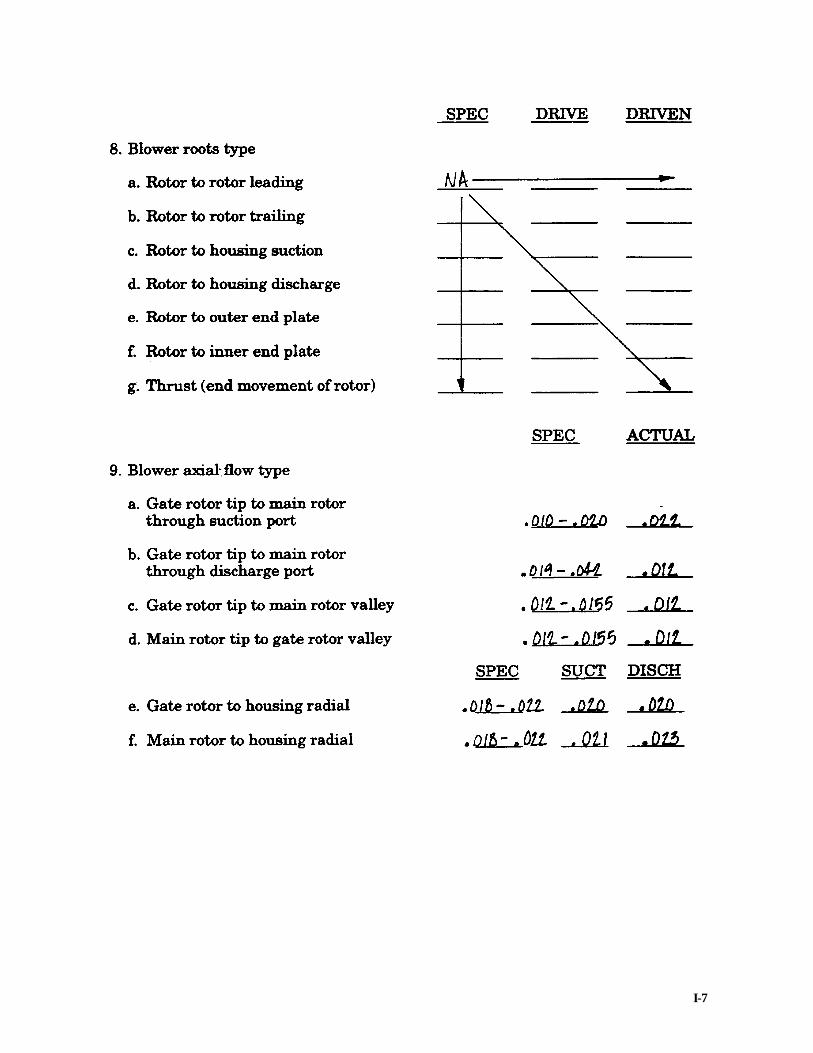
I-7

I-8

I-9
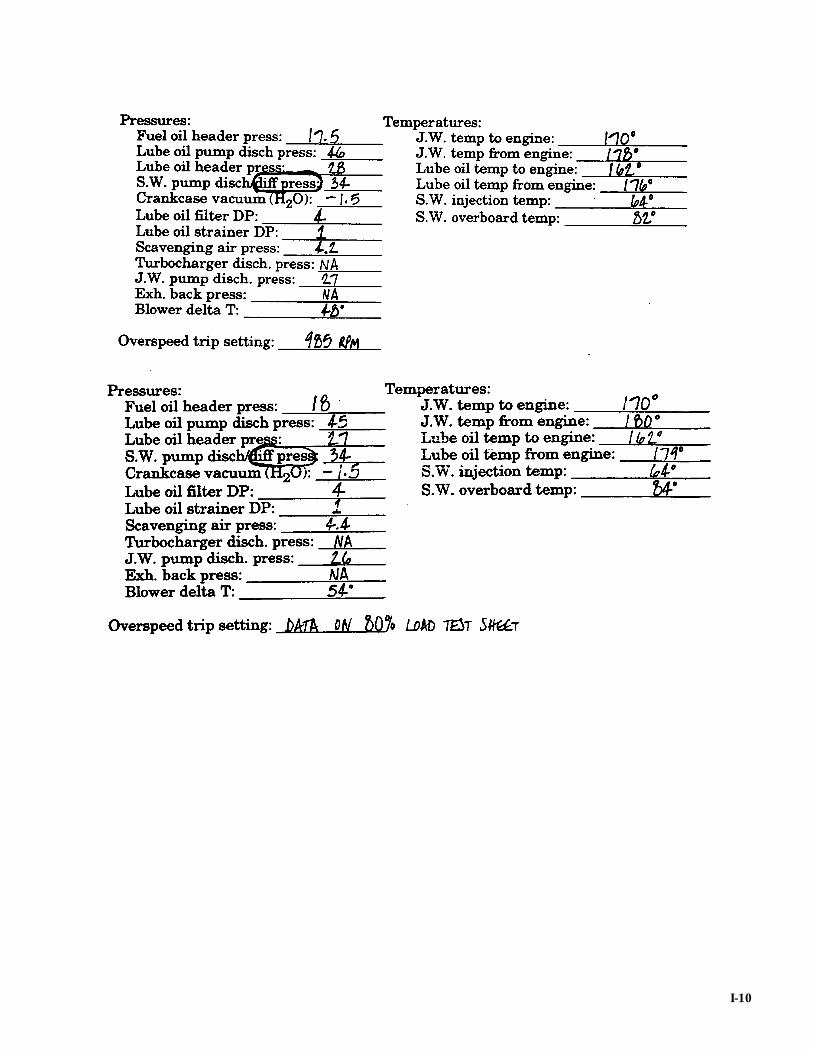
I-10