navsea standard item numerical index fy-15 · 3.1.1 in the event difficulty is encountered in...
TRANSCRIPT

1 of 8 FY-15
NAVSEA STANDARD ITEM NUMERICAL INDEX FY-15
ITEM NO.
TITLE
UTILIZATION CATEGORY
DATE
009-01 General Criteria; accomplish I 07 NOV 2013
009-02 Environmental Compliance Reports for Material Usage at Naval Facilities; provide
I 29 JUL 2011
009-03 Toxic and Hazardous Substances; control
I 17 JAN 2013
009-04 Quality Management System; provide I 07 NOV 2013
009-05 Temporary Accesses; provide I 17 JAN 2013
009-06 Maintaining Protection and Cleanliness from Non-Radioactive Operations; accomplish
I 17 JAN 2013
009-07 Confined Space Entry, Certification, Fire Prevention and Housekeeping; accomplish
I 17 JAN 2013
009-08 Fire Protection at Contractor's Facility; accomplish
I 07 NOV 2013
009-09 Process Control Procedure (PCP); provide and accomplish
II 06 JAN 2014
009-10 Shipboard Asbestos-Containing Material (ACM); control
I 29 JUL 2011
009-11 Insulation and Lagging Requirements; accomplish
II 17 JAN 2013
009-12 Welding, Fabrication, and Inspection Requirements; accomplish
II 07 NOV 2013
009-13 Meters; repair and certify calibration
II 17 JAN 2013
009-14 Gages and Thermometers; repair and certify calibration
II 17 JAN 2013
009-15 Rotating Machinery; balance II 17 JAN 2013
009-16 Electronic Equipment; repair II 29 JUL 2011

2 of 8 FY-15
ITEM NO.
TITLE
UTILIZATION CATEGORY
DATE
009-17 Rotating Electrical Equipment; repair
II 07 NOV 2013
009-18 Magnetic Material; control I 17 JAN 2013
009-19 Provisioning Technical Documentation (PTD); provide
I 29 JUL 2011
009-20 Government Property; control I 17 JAN 2013
009-21 Logistics and Technical Data; provide
I 29 JUL 2011
009-22 Shipboard Electric Cable; test II 17 JAN 2013
009-23 Interferences; remove and install I 17 JAN 2013
009-24 Authorization, Control, Isolation, Blanking, and Tagging Requirements; accomplish
I 17 JAN 2013
009-25 Structural Boundary Test; accomplish
II 17 JAN 2013
009-26 Deck Covering Requirements; accomplish
II 17 JAN 2013
009-27 Material Identification and Control (MIC) for Level I Systems; accomplish
II 07 NOV 2013
009-28 Cancelled 30 JUL 2010
009-29 Asbestos-Free Pipe Hanger Liner Material; install
I 29 JUL 2004
009-30 Boiler Sample Tubes; inspect II 29 JUL 2011
009-31 Boiler Waterjet Cleaning; accomplish
II 29 JUL 2011
009-32 Cleaning and Painting Requirements; accomplish
II 07 NOV 2013
009-33 Rotating Electrical Equipment; rewind
II 07 NOV 2013
009-34 Fire Protection of Unmanned Vessels at Contractor's Facility; provide
I 17 JAN 2013

3 of 8 FY-15
ITEM NO.
TITLE
UTILIZATION CATEGORY
DATE
009-35 Confined Space Entry, Certification, Fire Prevention Utilizing Military Fire Watches, and Housekeeping; accomplish
I 07 NOV 2013
009-36 Controller; repair II 29 JUL 2011
009-37 General Procedures for Woodwork; accomplish
II 30 JUL 2010
009-38 Boiler Dry Lay-up; accomplish II 17 JAN 2013
009-39 Technical Manual Contract Requirement (TMCR) for New Technical Manuals for Commercial Equipment/Component; provide
I 19 JUL 2007
009-40 Requirements for Contractor Cranes, Multi-Purpose Machines and Material Handling Equipment at Naval Facilities; accomplish
I 29 JUL 2011
009-41 Technical Manual Contract Requirement (TMCR) for a Topically Structured Technical Manual; provide
II 19 JUL 2007
009-42 Technical Manual Contract Requirement (TMCR) for Updating Technical Manuals; provide
II 19 JUL 2007
009-43 Light-Off Assessment (LOA) Support for Steam Propulsion System; provide
II 17 JAN 2013
009-44 Light-Off Assessment (LOA) Support for Gas Turbine Propulsion System; provide
II 07 NOV 2013
009-45 Tapered Plug Valve; repair II 29 JUL 2011
009-46 Butterfly Valve, Synthetic and Metal Seated; repair
II 17 JAN 2013
009-47 Gate Valve; repair II 29 JUL 2011
009-48 Pressure Seal Bonnet Valve; repair (shop)
II 29 JUL 2011
009-49 Pressure Seal Bonnet Valve; repair (in-line)
II 29 JUL 2011

4 of 8 FY-15
ITEM NO.
TITLE
UTILIZATION CATEGORY
DATE
009-50 Horizontal Swing Check Valve; repair
II 29 JUL 2011
009-51 Globe, Globe Angle, and Globe Stop Check Valve; repair
II 17 JAN 2013
009-52 Relief Valve; repair II 29 JUL 2011
009-53 Bolted Bonnet Steam Valve; repair (shop)
II 29 JUL 2011
009-54 Bolted Bonnet Steam Valve; repair (in-line)
II 30 JUL 2010
009-55 Regulating/Reducing Valve; repair II 30 JUL 2010
009-56 Main Propulsion Boiler Wet Lay-up; accomplish
II 29 JUL 2011
009-57 Reduction Gear Security Requirements; accomplish
II 17 JAN 2013
009-58 Pump and Driver Shaft Alignment; accomplish
II 17 JAN 2013
009-59 Organotin Antifouling Materials; control
I 29 JUL 2011
009-60 Schedule and Associated Reports for Availabilities Over 9 Weeks in Duration; provide and manage
I 07 NOV 2013
009-61 Shipboard Use of Fluorocarbons; control
I 17 JAN 2013
009-62 Boiler Handhole and Manhole Seats and Plates; inspect
II 29 JUL 2011
009-63 Lubricating Oils and Hydraulic Fluids; analyze
II 29 JUL 2011
009-64 Synthetic Fire Resistant Hydraulic Fluid; control
I 29 JUL 2011
009-65 Polychlorinated Biphenyls (PCBs); control
I 29 JUL 2011
009-66 Light-Off Assessment (LOA) Support for Diesel Propulsion System; provide
II 17 JAN 2013
009-67 Integrated Total Ship Testing; manage
I 17 JAN 2013
5 of 8 FY-15
ITEM NO.
TITLE
UTILIZATION CATEGORY
DATE
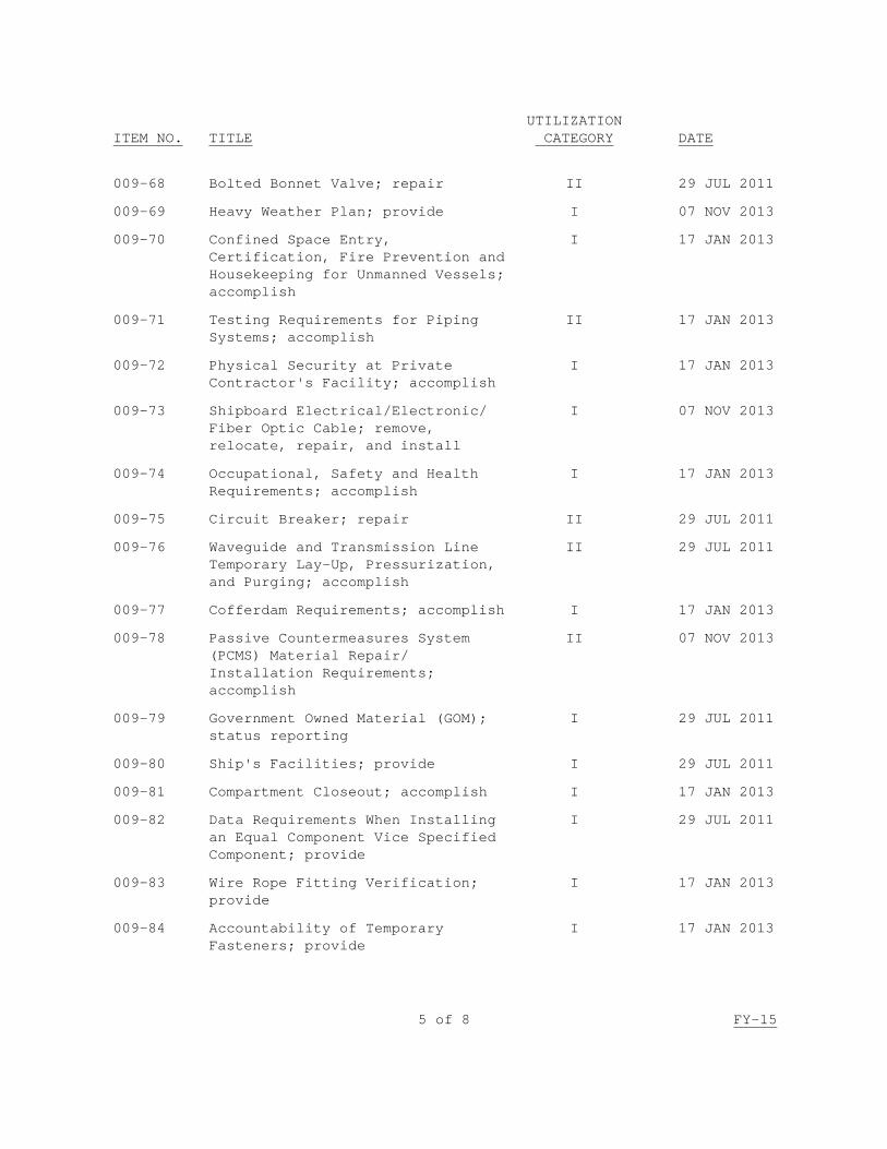
009-68 Bolted Bonnet Valve; repair II 29 JUL 2011
009-69 Heavy Weather Plan; provide I 07 NOV 2013
009-70 Confined Space Entry, Certification, Fire Prevention and Housekeeping for Unmanned Vessels; accomplish
I 17 JAN 2013
009-71 Testing Requirements for Piping Systems; accomplish
II 17 JAN 2013
009-72 Physical Security at Private Contractor's Facility; accomplish
I 17 JAN 2013
009-73 Shipboard Electrical/Electronic/ Fiber Optic Cable; remove, relocate, repair, and install
I 07 NOV 2013
009-74 Occupational, Safety and Health Requirements; accomplish
I 17 JAN 2013
009-75 Circuit Breaker; repair II 29 JUL 2011
009-76 Waveguide and Transmission Line Temporary Lay-Up, Pressurization, and Purging; accomplish
II 29 JUL 2011
009-77 Cofferdam Requirements; accomplish I 17 JAN 2013
009-78 Passive Countermeasures System (PCMS) Material Repair/ Installation Requirements; accomplish
II 07 NOV 2013
009-79 Government Owned Material (GOM); status reporting
I 29 JUL 2011
009-80 Ship's Facilities; provide I 29 JUL 2011
009-81 Compartment Closeout; accomplish I 17 JAN 2013
009-82 Data Requirements When Installing an Equal Component Vice Specified Component; provide
I 29 JUL 2011
009-83 Wire Rope Fitting Verification; provide
I 17 JAN 2013
009-84 Accountability of Temporary Fasteners; provide
I 17 JAN 2013

6 of 8 FY-15
ITEM NO.
TITLE
UTILIZATION CATEGORY
DATE
009-85 Government Sponsored Planning Yard/Configuration Data Manager (CDM) On-Site Representative Facility; provide
II 19 JUL 2007
009-86 Recovery of Chlorofluorocarbon (CFC's) and Fire Suppressant Halon (H) Materials; accomplish
I 01 AUG 2008
009-87 Chemical Disinfection Procedures; accomplish
I 17 JAN 2013
009-88 Collection, Holding and Transfer (CHT) and Mogas Tanks, Spaces, and Piping, including Sewage or Mogas-Contaminated Tanks, Spaces, and Piping; certify
I 29 JUL 2011
009-89 Purchase and Inspection Requirements for Contractor Furnished Anodes; accomplish
I 29 JUL 2011
009-90 Technical Representative; provide II 07 NOV 2013
009-91 Propeller In-Place Inspection; accomplish
II 07 NOV 2013
009-92 Resilient Mount; remove and install
II 29 JUL 2011
009-93 Emergency Planning and Community Right-to-Know Act (EPCRA) and Pollution Prevention Act (PPA) Information; provide
I 17 JAN 2013
009-94 General Environmental Requirements for Work at Contractor's Facility; accomplish
I 17 JAN 2013
009-95 Mechanically Attached Fittings (MAFs) for Piping Systems; install
I 17 JAN 2013
009-96 Ball Valve; repair II 29 JUL 2011
009-97 Shipbuilding and Ship Repair Operations National Emission Standard for Hazardous Air Pollutants (NESHAPS) for Surface Coating Information; provide
I 17 JAN 2013
009-98 Monel Fasteners; inspect II 30 JUL 2010

7 of 8 FY-15
ITEM NO.
TITLE
UTILIZATION CATEGORY
DATE
009-99 Ship Departure Report; provide I 17 JAN 2013
009-100 Ship's Stability Process Control Procedure (PCP); maintain
I 30 JUL 2010
009-101 Requirements for Mooring, Entry to, and Departure from Contractor's Facility; accomplish
I 17 JAN 2013
009-102 Alteration Verification; provide I 29 JUL 2011
009-103 Weight and Moment Change Data; provide
I 29 JUL 2011
009-104 Vibration Testing and Analysis; accomplish
II 29 JUL 2011
009-105 Thermal Sprayed Coatings for Machinery Component Repair; accomplish
II 17 JAN 2013
009-106 Work Authorization Form Coordinator (WAFCOR); provide
I 06 JAN 2014
009-107 Piping System Cleanliness (Non-Nuclear); accomplish
II 17 JAN 2013
009-108 Aircraft Carrier Requirements for Mooring, Entry to, Movement within, and Departure from Contractor's Facility; accomplish
I 29 JUL 2011
009-109 Special Requirements for Non-SUBSAFE Work on SUBSAFE-Certified Vessels; accomplish
I 29 JUL 2011
009-110 Special Requirements for Non-Nuclear Work on Nuclear Vessels; accomplish
I 29 JUL 2011
009-111 Schedule and Associated Reports for Availabilities 9 Weeks or Less in Duration; provide and manage
I 07 NOV 2013
009-112 Prevention of Radiographic-Inspection Ionizing-Radiation Hazards; accomplish
I 29 JUL 2011

8 of 8 FY-15
ITEM NO.
TITLE
UTILIZATION CATEGORY
DATE
009-113 Rotating Electrical Equipment with Sealed Insulation Systems (SIS); rewind
II 07 NOV 2013
009-114 Mold Remediation; accomplish II 07 NOV 2013
009-115 Bearing Rebabbitting; accomplish II 07 NOV 2013
009-116 Auxiliary and Waste Heat Boiler Sodium Nitrite Wet Lay-up; accomplish
II 29 JUL 2011
009-117 AEGIS Light-Off (ALO) Support for AEGIS Weapons Systems; provide
I 06 JAN 2014
009-118 CG Deck Loading; accomplish I 17 JAN 2013
009-119 Expanded Process Control Procedure (EPCP); provide and accomplish
II 06 JAN 2014
009-120 Fact Finding and Critique of Unplanned Events; manage
I 06 JAN 2014
009-121 Ship Assessment/Inspection Requirements; provide
I 06 JAN 2014

1 of 9 ITEM NO: 009-01 FY-15
NAVSEA STANDARD ITEM
FY-15 ITEM NO: 009-01 DATE: 07 NOV 2013 CATEGORY: I 1. SCOPE: 1.1 Title: General Criteria; accomplish 2. REFERENCES: 2.1 40 CFR Part 61, National Emission Standards for Hazardous Air
Pollutants
3. REQUIREMENTS: 3.1 Report delays to the SUPERVISOR. 3.1.1 In the event difficulty is encountered in meeting requirements or difficulty is anticipated in complying with the contract schedule dates, notify the SUPERVISOR immediately by verbal means, followed on the next work day by an original and 2 copies of a letter stating pertinent details. Receipt of this notification by the SUPERVISOR is not to be construed as a waiver of the requirements, delivery schedule by the Government, or waiver of rights or remedies provided by law or under this Job Order or any other requirements in the Job Order relating to jeopardy of contract schedule dates. 3.2 Reports: 3.2.1 When a Work Item does not require a report, and one is determined to be necessary in order to produce a reliable or complete repair, submit one legible copy, in approved transferrable media, of a report with supporting data as early as possible in the contract period. The goal is to have required work completed within the original contract period. 3.2.2 For reports that could result in a change in work to be accomplished or additional material to be procured, complete the preliminary work and submit one legible copy, in approved transferrable media, of the report in a time frame to allow the SUPERVISOR to initiate early action, but no later than the first 20 percent of the availability. 3.2.3 Submit one legible copy, in approved transferrable media, of the following to the SUPERVISOR one working day prior to the weekly progress meeting:

2 of 9 ITEM NO: 009-01 FY-15
3.2.3.1 A report listing Government Furnished Material not received, showing the associated Work Item number and title, material description, expected delivery date, required delivery date, and action proposed to resolve problems resulting from late delivery. Material with expected delivery dates before the required delivery date need not be listed in this report. 3.2.3.2 A report listing late or deficient Government Furnished Information, showing the associated Work Item number, deficiency description, and proposed corrective action. 3.2.3.3 A report of overdue contractor condition reports by Work Item number and expected submission date. The report shall also include those deficiency and condition reports for which Government response is outstanding. 3.2.4 Dry dock related inspection reports shall be submitted no later than the first 20 percent of the scheduled docking period. Dry dock related reports which contain readings (final, thickness, etc.), clearances, alignments, test results, or other such data for work that has to be completed prior to pre-flood/undocking, shall be submitted to the SUPERVISOR within 24 hours after recording the data but no later than 72 hours prior to pre-flood/undocking, whichever occurs first. 3.2.5 Reports shall contain the following information: 3.2.5.1 Name and hull number of ship or craft, the Job Order, Work Item, and paragraph numbers including Standard Item paragraph number if applicable. 3.2.5.2 A description of the conditions found with supporting data. Include annotated sketches, graphs, and photographs when necessary to make a report clearly understandable to the SUPERVISOR. Identify actual readings/dimensions taken. 3.2.5.3 Recommendations and/or a list of material required. 3.2.5.4 Data required by, signature, printed name, and title of the contractor's representative, and submission date. 3.2.6 Prepare and submit one legible copy, in approved transferrable media, of a listing of all reports, Process Control Procedures (PCP), and Expanded Process Control Procedures (EPCP) required by the CNO/CMAV Job Order to the SUPERVISOR no later than 15 days prior to the start of the CNO/CMAV availability. The listing shall be sequential by Work Item number, and include each applicable paragraph number, PCP/EPCP/report due date, completion date, submission date, and a provision for adding report serial numbers from NMD. 3.2.6.1 The report shall be revised and provided weekly throughout the availability to include additions, deletions, modifications,
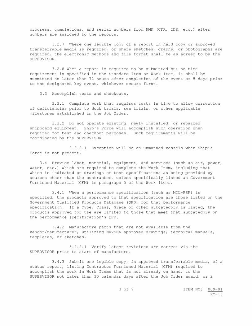
3 of 9 ITEM NO: 009-01 FY-15
progress, completions, and serial numbers from NMD (CFR, IDR, etc.) after numbers are assigned to the reports. 3.2.7 Where one legible copy of a report in hard copy or approved transferrable media is required, or where sketches, graphs, or photographs are required, the electronic methods and file format shall be as agreed to by the SUPERVISOR. 3.2.8 When a report is required to be submitted but no time requirement is specified in the Standard Item or Work Item, it shall be submitted no later than 72 hours after completion of the event or 5 days prior to the designated key event, whichever occurs first. 3.3 Accomplish tests and checkouts. 3.3.1 Complete work that requires tests in time to allow correction of deficiencies prior to dock trials, sea trials, or other applicable milestones established in the Job Order. 3.3.2 Do not operate existing, newly installed, or repaired shipboard equipment. Ship's Force will accomplish such operation when required for test and checkout purposes. Such requirements will be coordinated by the SUPERVISOR. 3.3.2.1 Exception will be on unmanned vessels when Ship’s Force is not present. 3.4 Provide labor, material, equipment, and services (such as air, power, water, etc.) which are required to complete the Work Item, including that which is indicated on drawings or test specifications as being provided by sources other than the contractor, unless specifically listed as Government Furnished Material (GFM) in paragraph 5 of the Work Items. 3.4.1 When a performance specification (such as MIL-PRF) is specified, the products approved to that specification are those listed on the Government Qualified Products Database (QPD) for that performance specification. If a Type, Class, Grade or other subcategory is listed, the products approved for use are limited to those that meet that subcategory on the performance specification’s QPD. 3.4.2 Manufacture parts that are not available from the vendor/manufacturer, utilizing NAVSEA approved drawings, technical manuals, templates, or sketches. 3.4.2.1 Verify latest revisions are correct via the SUPERVISOR prior to start of manufacture. 3.4.3 Submit one legible copy, in approved transferrable media, of a status report, listing Contractor Furnished Material (CFM) required to accomplish the work in Work Items that is not already on hand, to the SUPERVISOR not later than 30 calendar days after the Job Order award, or 2

4 of 9 ITEM NO: 009-01 FY-15
calendar days after availability start date, whichever occurs first. Update the report and submit revisions to the SUPERVISOR every 2 weeks up to availability start date, within 10 days after availability start date, then monthly thereafter to End of Availability (EOA). The reports are to contain the following: 3.4.3.1 Contract number 3.4.3.2 Contractor's purchase order number 3.4.3.3 Description of material 3.4.3.4 Quantity ordered 3.4.3.5 Date scheduled to be ordered 3.4.3.6 Date ordered 3.4.3.7 Date required to meet production schedule 3.4.3.8 Proposed receipt date 3.4.3.9 A summary listing any problem areas 3.4.3.10 Date submitted to the SUPERVISOR 3.4.3.11 Alteration number 3.4.3.12 Drawing and piece number 3.4.3.13 Manufacturer 3.4.3.14 Manufacturer's part number 3.4.3.15 Date received 3.4.3.16 Work Item number 3.4.4 Purchase Orders 3.4.4.1 Maintain a file of purchase orders for CFM for review by the SUPERVISOR upon request. 3.4.4.2 Submit one legible copy, in approved transferrable media, of selected purchase orders to the SUPERVISOR upon request. 3.5 Externally threaded fastener installation acceptance criteria unless otherwise specified or approved: 3.5.1 The minimum thread protrusion for male threaded fasteners shall be one full thread beyond the face of the nut. The maximum thread
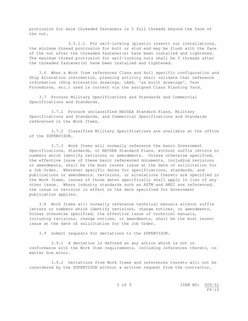
5 of 9 ITEM NO: 009-01 FY-15
protrusion for male threaded fasteners is 5 full threads beyond the face of the nut. 3.5.1.1 For self-locking (plastic insert) nut installations, the minimum thread protrusion for bolt or stud end may be flush with the face of the nut after the threaded fastener(s) have been installed and tightened. The maximum thread protrusion for self-locking nuts shall be 5 threads after the threaded fastener(s) have been installed and tightened. 3.6 When a Work Item references Class and Hull specific configuration and Ship Alteration information, planning activity shall validate that reference information (Ship Alteration drawings, LARS, "as built drawings", Test Procedures, etc.) used is correct via the assigned Class Planning Yard. 3.7 Procure Military Specifications and Standards and Commercial Specifications and Standards. 3.7.1 Procure unclassified NAVSEA Standard Plans, Military Specifications and Standards, and Commercial Specifications and Standards referenced in the Work Items. 3.7.2 Classified Military Specifications are available at the office of the SUPERVISOR. 3.7.3 Work Items will normally reference the basic Government Specifications, Standards, or NAVSEA Standard Plans, without suffix letters or numbers which identify revisions or amendments. Unless otherwise specified, the effective issue of these basic referenced documents, including revisions or amendments, shall be the most recent issue at the date of solicitation for a Job Order. Wherever specific dates for specifications, standards, and publications or amendments, revisions, or alterations thereto are specified in the Work Items, issues of those dates specifically shall apply in lieu of any other issue. Where industry standards such as ASTM and ANSI are referenced, the issue or revision in effect on the date specified for Government publication applies. 3.8 Work Items will normally reference technical manuals without suffix letters or numbers which identify revisions, change notices, or amendments. Unless otherwise specified, the effective issue of technical manuals, including revisions, change notices, or amendments, shall be the most recent issue at the date of solicitation for the Job Order. 3.9 Submit requests for deviations to the SUPERVISOR. 3.9.1 A deviation is defined as any action which is not in conformance with the Work Item requirements, including references thereto, no matter how minor. 3.9.2 Deviations from Work Items and references thereto will not be considered by the SUPERVISOR without a written request from the contractor.

6 of 9 ITEM NO: 009-01 FY-15
3.9.3 Submit one legible copy, in approved transferrable media, of requests for deviations to the SUPERVISOR within 24 hours of identifying the deviation. 3.9.4 The Government does not have an obligation to approve any deviation; it may elect to do so if benefit to the Government can be shown. Accomplish deviation only when authorized in writing by the SUPERVISOR. 3.10 Accomplish the requirements of the contract. 3.11 Comply with security requirements. 3.11.1 In the event that the work required by the Job Order requires access to spaces or equipment that are classified, or use of technical manuals, references, or drawings that are classified, the specific security clearance requirements will be identified in the individual Work Item in addition to the requirements provided in the Invitation for Bid/Request for Proposal (IFB/RFP) by the Contract Security Classification Specification (DD Form 254). 3.11.2 Verify that personnel, including subcontractor's personnel, are cleared for the required level of security classification for handling, repair, installation, and testing of classified equipment and for access to areas of the ship which require a specific security clearance. 3.11.2.1 After selection of a subcontractor, prepare in triplicate a DD Form 254 for the subcontract and request the official designated in Paragraph 14.b of the DD Form 254 for the prime contract to approve and sign the DD Form 254 for the subcontract and to make the required distribution. In preparing the DD Form 254 for subcontracts, extract pertinent data from the DD Form 254 pertaining to the prime contract. 3.11.2.2 Prior to starting work on a Work Item that requires a security clearance, submit a list in triplicate of the names, badge numbers or other identification numbers, and security clearances of contractor and subcontractor personnel who will require access to classified information or areas in order to accomplish the work. 3.11.3 Verify that classified equipment removed from ship and classified documents, such as drawings, technical manuals, and test specifications, are marked or tagged and safeguarded at all times in accordance with the National Industrial Security Program Operating Manual (DOD 5220.22-M). 3.12 Comply with applicable federal, state, and local laws, codes, ordinances, and regulations in their entirety. Any reference to a specific portion of a federal, state, or local law, code, ordinance, or regulation in this or any other item shall not be construed to mean that relief is provided from any other sections of the law, code, ordinance, or regulation.

7 of 9 ITEM NO: 009-01 FY-15
3.12.1 Provide appropriate notification to regional United States Environmental Protection Agency (EPA) in accordance with the requirements of 2.1. Also, comply with notification requirements of state and local air pollution control laws. 3.12.2 Submit one legible copy, in approved transferrable media, of notification required in 3.12.1 that has been provided to any regulatory authority for work on board the vessel to the SUPERVISOR within 2 working days of providing such notice to the regulatory authority. 3.13 Maintain a current copy at the job site of the Material Safety Data Sheet for each hazardous material that will be utilized aboard the ship and/or in a Navy facility during the performance of this Job Order. Submit one legible copy, in hard copy or approved transferrable media, to the SUPERVISOR upon request. 3.13.1 Each MSDS requires a one-time submittal/acceptance unless the MSDS changes or this NAVSEA Standard Item and/or references change. 3.14 Comply with applicable federal, state, local, and foreign contractor host country requirements when using Nuclear Regulatory Commission (NRC) licensed radioactive material, Agreement State licensed radioactive material, and/or machine sources of ionizing radiation on Government property. 3.14.1 Do not commence operations using radioactive material or machine sources of ionizing radiation on Government property until authorized by NAVSEADET RASO, via the SUPERVISOR. NAVSEADET RASO's address/telephone number is: Naval Sea Systems Command Detachment Radiological Affairs Support Office 160 Main Rd. Yorktown, VA 23691 (757) 887-4692 PLAD: NAVSEA DET RASO YORKTOWN VA (UC) 3.14.2 Contract personnel shall not be used as operators under a Navy Radioactive Material Permit (NRMP) issued to a naval facility. Navy personnel shall not be used as operators under a Nuclear Regulatory Commission (NRC) or Agreement State License issued to a contractor. 3.14.3 Submit one legible copy, in approved transferrable media, of a consolidated inventory of all ionizing radiation producing machines or material that will be utilized aboard the ship and/or naval facility during the performance of this Job Order to NAVSEADET RASO, via the SUPERVISOR, 5 working days prior to the start of work. 3.14.4 Submit one legible copy, in approved transferrable media, of the applicable NRC or Agreement State License including procedures regarding system process and operation for use of licensed radioactive material, to NAVSEADET RASO, via the SUPERVISOR 5 days prior to the start of work.

8 of 9 ITEM NO: 009-01 FY-15
Agreement State licensees shall provide evidence of NRC Form 241 (Report of Proposed Activities in a Non-Agreement State) with the copy of the license for Agreement State licensees. 3.14.5 Submit one legible copy, in approved transferrable media, of the applicable State license, authorization, or registration for machines that produce ionizing radiation, to NAVSEADET RASO, via the SUPERVISOR 5 days prior to the start of work. 3.14.6 Submit one legible copy, in approved transferrable media, of a formal Radiological Safety Plan which shall include operating and emergency procedures pertinent to the items listed in 3.14.3, and actions to control jobsite-boundary radiation exposures below those allowed for members of the general public under NRC and OSHA standards, to NAVSEADET RASO, via the SUPERVISOR 5 days prior to the start of work. 3.14.7 Provide NAVSEADET RASO, via the SUPERVISOR, with remedies to any radiation safety shortcomings identified by NAVSEADET RASO, to be rectified prior to commencing operations. 3.15 Correct errors in record keeping by drawing a single line through the error, recording the correct entry, initialing, dating, and printing the name of the person making the correction. 3.16 Record and Certification Signature Block or signature shall be legible and in ink. Erasures, write-overs, white-outs, ditto marks, continuation arrows, signature stamps, etc., are not acceptable. 3.16.1 Copying records to "make them neat" is not allowed. 3.16.2 Electronic records shall utilize electronic signature controls for certification of individual providing signature.
3.17 Do not commence operations that could compromise watertight integrity during waterborne availabilities until confirmation by the SUPERVISOR that the ship has at least one back-up power source immediately available for providing power of minimum load to support firefighting and dewatering equipment in the event of loss of shore power. 3.18 Protect the ship and its equipment from damage. 4. NOTES: 4.1 The term "day" means 24 hours prior to or after the scheduled event.

9 of 9 ITEM NO: 009-01 FY-15
4.2 Known sources for unclassified military specifications and standards are: https://mercury.tdmis.navy.mil https://assist.dla.mil http://www.assistdocs.com http://quicksearch.dla.mil 4.3 The term “SUPERVISOR” is defined as the local Government activity responsible for the execution and contract administration of Navy maintenance and modernization work. 4.4 The term "Job Order" is synonymous with the term "Contract" and “Task Order”. 4.5 One complete thread or one thread length is defined as one complete rotation (360 degrees on a single thread), starting at a point along the thread. 4.6 Deviation from the maximum 5-thread protrusion in way of stud installations in blind holes will require the contractor to verify that the stud was installed to the proper thread depth prior to submitting a request for deviation. 4.7 The term “approved transferrable media” is the form, system or program for submitting reports required as agreed to by the SUPERVISOR. 4.8 The term “subcontract” means any contract as defined in the FAR, Subpart 2.1, entered into by a subcontractor to furnish supplies or services for performance of a prime contract or a subcontract. It includes but is not limited to purchase orders, and changes and modifications to purchase orders.


1 of 3 ITEM NO: 009-02 FY-15
NAVSEA STANDARD ITEM FY-15 ITEM NO: 009-02 DATE: 29 JUL 2011 CATEGORY: I 1. SCOPE: 1.1 Title: Environmental Compliance Reports for Material Usage at Naval
Facilities; provide 2. REFERENCES: 2.1 42 USC 7412(b), Clean Air Act, Section 112(b), List of Hazardous Air
Pollutants 3. REQUIREMENTS: 3.1 Submit one legible copy, in approved transferrable media, of reports as follows: 3.1.1 Submit applicable permits for portable, registered, or rental emission units to the SUPERVISOR prior to start of work. 3.1.2 Establish a record-keeping program to reflect the manner in which the material records will be maintained and submitted to the SUPERVISOR. 3.1.3 Maintain facility specific records to ensure accurate reporting for all preservation, welding repairs, and fuel consumption for each individual portable internal combustion engine or portable emission unit. Provide the SUPERVISOR sufficient details to track usage of all paints, solvents, adhesives, welding rods, and fuel used for each individual portable internal combustion engine over 50-brake horsepower. Report any other materials used which contain chemicals listed in 2.1. 3.1.4 Maintain current usage records of materials listed in 2.1. 3.1.5 Negative reports are required. 3.1.6 Reports shall contain the following items based upon category of the material. 3.1.7 Paint, solvent, adhesive, and nonskid usage records are to be submitted monthly and shall include the following: 3.1.7.1 Product manufacturer, identification or color

2 of 3 ITEM NO: 009-02 FY-15
3.1.7.2 Net daily paint usage in gallons, paint application method (airless spray, HVLP, brush, or roller) per paint type, amount of paint disposed as hazardous waste; density of mixed paint; net daily onsite solvent usage in gallons used for equipment cleaning and surface preparation; net amount of adhesives in unit of measure (ounces, quart, gallons or pound) 3.1.7.3 Product material safety data sheet (MSDS), technical data sheet, VOC certification for paint and nonskid product 3.1.7.4 Government site location, applicable local Air Pollution Control District (APCD) permit number, date, and ship's name 3.1.8 Abrasive blast grit materials used shall be submitted monthly and shall include: 3.1.8.1 Manufacturer of abrasive blast grit and MSDS 3.1.8.2 Abrasive blast grit usage certification if required by the cognizant state or local authorities 3.1.8.3 Amount and hourly usage of the abrasive blast grit 3.1.8.4 Permit associated with the abrasive blasting equipment if required by the cognizant state or local authorities 3.1.9 Welding operation report shall be submitted monthly and shall include welding rod manufacturer, specific product used in welding application, MSDS, usage in pounds, and type of welding application 3.1.10 Portable internal combustion (IC) engine greater than 50 brake horse power operation report shall be submitted monthly and shall include: 3.1.10.1 Amount of fuel used in gallons and the hours of operation 3.1.10.2 IC engine permit number and site location if required by the cognizant state or local authorities 3.2 Submit one legible copy, in approved transferrable media, of each report required by 3.1 to the SUPERVISOR no later than 10 calendar days after the end of the month throughout the availability. 4. NOTES: 4.1 Examples of paint and nonskid manufacturers may be Ameron, International, American Safety Technology, or others as applicable. 4.2 Examples of American Welding Society Classifications for welding rod may be E316-16, E7018-AL 308-16, or others. If there is no American Welding

3 of 3 ITEM NO: 009-02 FY-15
Society (AWS) classification assigned, use the product name and circle the product on the MSDS. 4.3 Examples of welding applications may be Shielded Metal Arc Weld (SMAW), Gas Metal Arc Weld (GMAW), Flux Core Arc Weld (FCAW), and others.


1 of 3 ITEM NO: 009-03 FY-15
NAVSEA STANDARD ITEM FY-15 ITEM NO: 009-03 DATE: 17 JAN 2013 CATEGORY: I 1. SCOPE: 1.1 Title: Toxic and Hazardous Substances; control 2. REFERENCES: 2.1 29 CFR Part 1915, Occupational Safety and Health Standards for
Shipyard Employment 3. REQUIREMENTS: 3.1 Identify materials that may contain toxic or hazardous substances as listed in Subpart Z of 2.1 that are to be used, removed, or disturbed during work operations. 3.1.1 Conduct and document an initial determination of potential personnel exposure to these materials prior to the start of work. 3.1.1.1 Provide a copy of the documentation, signed by a competent person as defined in 29 CFR 1915.4, to the SUPERVISOR upon request. 3.2 Ensure that work operations comply with the requirements of 2.1 for the use of toxic or hazardous substances and removal or disruption of existing toxic or hazardous substances. 3.3 Ensure that processes or procedures for the removal or disruption of existing toxic or hazardous substances comply with the requirements of 2.1. At a minimum, address the following: exposure monitoring, method of compliance, respiratory protection, protective clothing, housekeeping, hygiene facilities and practices, medical surveillance, employee information and training, signs, and recordkeeping. 3.3.1 Submit one legible copy of process or procedure, in approved transferrable media, when requested by the SUPERVISOR. 3.4 Provide a notice to the SUPERVISOR and to the Commanding Officer's designated representative. 3.4.1 Post the notice at the ship's Quarterdeck and at all entrances to the work areas for each job or separate area of potential exposure to toxic

2 of 3 ITEM NO: 009-03 FY-15
or hazardous substances and hazardous operations at least 4 hours, but not more than 24 hours, prior to the start of work. 3.4.2 The notice shall contain the following information: 3.4.2.1 Ship's name and hull number 3.4.2.2 Work Item number 3.4.2.3 Compartment or frame number 3.4.2.4 Identification of hazard 3.4.2.5 Date and time of work process 3.4.2.6 Identification of engineering and work practice controls 3.4.3 Deliver notification of work planned over a weekend or Monday following that weekend to the Commanding Officer's designated representative not later than 0900 on the Friday immediately preceding that weekend. 3.4.4 Deliver notification of work planned on a Federal holiday and on the day following the Federal holiday to the Commanding Officer's designated representative not later than 0900 on the last working day preceding the Federal holiday. 3.4.5 The notice shall be submitted to the SUPERVISOR for review prior to commencement of the work operation. Authorization of the SUPERVISOR shall be obtained before proceeding with the work. 3.5 Provide for isolation and blanking of ship's ventilation systems in work areas to prevent toxic or hazardous substance contamination of ventilation systems or other compartments/spaces. 3.6 Establish regulated areas for monitoring and authorized personnel entry whenever concentrations of the toxic or hazardous substance are in excess of exposure limits as listed in 2.1. 3.7 Monitor the affected areas during work operations to ensure compliance with 2.1. Monitoring shall include adjacent spaces to ensure the work area containments and work practices are effective. Results of surveillance shall be documented and documentation shall be made available to the SUPERVISOR.

3 of 3 ITEM NO: 009-03 FY-15
4. NOTES: 4.1 The term "hazardous substance" means a substance, which by reason of being explosive, flammable, poisonous, corrosive, oxidizing, irritant, or otherwise harmful is likely to cause injury. 4.2 Consider ventilation cleaning debris to contain toxic or hazardous substances.


1 of 10 ITEM NO: 009-04 FY-15
NAVSEA STANDARD ITEM
FY-15 ITEM NO: 009-04 DATE: 07 NOV 2013 CATEGORY: I 1. SCOPE: 1.1 Title: Quality Management System; provide 2. REFERENCES: 2.1 Standard Items 2.2 ANSI/ISO/ASQ Q9001-2008, Quality Management Systems - Requirements 2.3 ANSI/NCSL Z540-3, Requirements for the Calibration of Measuring and
Test Equipment 2.4 ISO/IEC 17025, General Requirements for the Competence of Testing
and Calibration Laboratories 2.5 NAVSEA 04-4734, Navy and Marine Corps Calibration Laboratory
Audit/Certification Manual 2.6 SSPC QP1 Application, Instructions, and Program Rules 3. REQUIREMENTS: 3.1 Establish, document, implement, and maintain a Quality Management System as a means of ensuring that product conforms to specified requirements. The system shall, as a minimum, comply with the requirements of 2.2 and all additional contract requirements. The Quality Management System (Quality Manual, documented procedures required by 2.2 and 3.1) shall be submitted to the SUPERVISOR for a document review and acceptance. The contractor shall have an acceptable documented Quality Management System, in accordance with this Standard Item, in place to receive an award of a Job Order. The Quality Management System shall be subject to periodic audits by the SUPERVISOR throughout the contract.
3.1.1 Include the following additional documented procedures: 3.1.2 Management Responsibility: Address all areas of Paragraphs 5.1 through 5.6.3, 6.1, 6.2.1, 6.2.2, and 8.5.1 of 2.2.

2 of 10 ITEM NO: 009-04 FY-15
3.1.3 Customer Related Processes: Address all areas of Paragraphs 7.2.1 through 7.2.3 of 2.2.
3.1.4 Purchasing: Address all areas of Paragraphs 7.4.1 through 7.4.3 of 2.2.
3.1.4.1 Verification of Purchased Product: Identify, in the
purchasing documents, verification arrangements at the subcontractor or vendors location/premises. Purchasing documents shall contain the following statement when the SUPERVISOR requests government inspection: "Government Inspection is required prior to shipment from your plant. Upon receipt of this order, promptly notify and furnish a copy to the government representative who normally services your plant so that appropriate planning for government inspection can be accomplished. In the event the government representative or office cannot be located, our purchasing agent shall be notified immediately."
3.1.4.2 Unless otherwise specified in a higher tier document,
Receipt Inspection of contractor furnished materials shall be based on supplier performance history and one or more of the following: certificate of compliance, vendor material test certification data, manufacturer's mill certificate, or testing using sampling techniques.
3.1.4.3 Use of black-oxide coated brass threaded fasteners
(BOCBTF) is not authorized in the accomplishment of any work under this contract.
3.1.5 Production and Service Provision: Address all areas of Paragraphs 7.5.1 - 7.5.5 of 2.2.
3.1.6 Monitoring and Measurement of Product: Address all areas of Paragraph 8.2.4 of 2.2. 3.1.7 Control of Monitoring and Measuring Devices: Address all areas of Paragraph 7.6 of 2.2. Calibration laboratories shall be accredited to either 2.3 or 2.4 by a Commercial Accreditation Activity, or certified by a Navy Certification Activity to 2.5, and the scope of accreditation must cover the appropriate measurement parameters and ranges of the calibrations performed. 3.1.8 Measurement, Analysis, and Improvement: Address all areas of Paragraphs 8.2.1, 8.4, and 8.5.1 of 2.2. 3.2 Submittal of procedures and Process Control Procedures (009-09 of 2.1) invoked by NAVSEA Standard Items, MIL-STDs, drawings, technical publications, and specifications, although an integral part of the Quality Management System, shall be submitted to and approved by the SUPERVISOR independent of the Quality Management System a minimum of 14 working days prior to use.

3 of 10 ITEM NO: 009-04 FY-15
3.3 Submit one legible copy, in hard copy or approved transferrable media, of any revisions to the accepted Quality Management System identified in 3.1 to the SUPERVISOR within 7 days of contractor approval. 3.4 The corrective and preventive action program shall require that a copy of the written responses to contractor generated corrective actions will be provided to the SUPERVISOR when requested. 3.5 Respond in writing to each SUPERVISOR issued Method B/C/D Corrective Action (CA) within 3 business days unless otherwise specified by the SUPERVISOR. Initial response shall include immediate corrective action taken and a plan of action for CA completion. Final response shall include preventive action for recurrence of identified nonconformance, root cause analysis and Objective Quality Evidence (OQE) for corrective action completed. 3.6 Attend or conduct fact-finding/investigative meetings when requested by the SUPERVISOR. 3.6.1 Submit one legible copy, in hard copy or approved transferrable media, of a report with responses for root cause analysis, and short term and long term corrective actions on all contractor-responsible problems identified to the SUPERVISOR within 5 calendar days after completion of meeting. 3.7 Develop a Test and Inspection Plan (TIP) incorporating each Work Item in the job order, LOA Chits or Statements of Work (SOW). The initial TIP shall include all inspections and tests required by zero-tier references and first tier references, as well as symbols (I)(V)(Q) test/inspections and (G) government notification identified in the Work Item, and any additional tests and inspections the contractor deems necessary to substantiate product conformance. Submit one legible copy, in hard copy or approved transferrable media, of initial copy of the TIP to the SUPERVISOR prior to productive work for non-CNO availabilities and no later than 5 days prior to the availability start date for CNO availabilities. 3.7.1 Submit one legible copy, in hard copy or approved transferrable media that can be sorted (e.g., Excel spreadsheet) of an updated TIP when requested by the SUPERVISOR. 3.7.2 A TIP shall: 3.7.2.1 Be revised prior to the start of productive work and updated as work proceeds on each Work Item. It shall be available upon request by the SUPERVISOR. Supporting data for tests and inspections requiring government notification (G), including accept/reject criteria, shall be available at the location of each test and inspection. Include provisions for documenting the date, time, and identification of the SUPERVISOR's representative notified and government representative attending each (G)-Point on the TIP. The TIP shall annotate the relationship to a

4 of 10 ITEM NO: 009-04 FY-15
specific key event. The following key events shall be considered at a minimum (as applicable): Undocking, Propulsion Plant Production Completion Date (PCD), Combat Systems Production Completion Date (CSPCD) or AEGIS Light-Off (ALO) for AEGIS ships, Dock Trials (DT), Fast Cruise (FC), Sea Trials (ST), and Availability Completion (CA). 3.7.2.2 Each test and inspection shall be identified by its respective Work Item number and Work Item paragraph number, including Standard Item paragraph number, and shall include inspection symbols (I)(Q) and (V), and the government notification (G) Point symbol where applicable. 3.7.3 Provide identification of the item to be inspected by name, number, and location (e.g., number 3 main feed pump, 5-180-0-E). 3.7.4 Provide identification of each characteristic of the items to be inspected and provide the criteria for acceptance for each characteristic (e.g., air test; 2 PSIG for 10 minutes; no drop). 3.8 Test and Inspection records shall: 3.8.1 Include the ship's name and hull number, Job Order and Work Item number, paragraph number, date, time, and signature of the contractor's authorized representative who witnessed or performed the test or inspection. The signature occurs after the checkpoint is determined to be satisfactory or unsatisfactory and any exceptions are documented. 3.8.2 Be maintained at a contractor location accessible to the site of the work required by the Job Order. 3.8.3 Be documented within 24 hours of accomplishment or prior to the subsequent tests or inspections, whichever is less. The records shall indicate the results of the test and or inspection accomplished. Records shall be incorporated into the TIP and the PCP/EPCP within 72 hours after completion of each test or inspection. 3.8.3.1 For tests and inspections involving (G)-points, records shall be documented upon acceptance or rejection and a hard copy (or electronic copy as authorized by the SUPERVISOR) provided to the SUPERVISOR at the conclusion of each (G)-Point. For tests and inspections utilizing Coating QA Tool Kit (CQATK) paperless QA program in accordance with 009-32 of 2.1, the data must be downloaded into the computer at the time and location of inspection. (See Note 4.5) 3.8.4 Required reports resulting from tests or inspections shall include the appropriate design criteria for each attribute or measurement required by the Work Item. 3.9 The SUPERVISOR will consider the Work Item incomplete if the contractor's documentation and records are not complete.

5 of 10 ITEM NO: 009-04 FY-15
3.10 Accomplish (I), (V) and (Q) tests/inspections that do not have associated (G)-points, with qualified and/or currently certified personnel where required by the technical documents (e.g., NBPI, NACE, nondestructive testing, electrical cableway inspection, etc.) as follows: 3.10.1 (I) inspections require verification and documentation by a separate individual, other than the person who has accomplished the work, who is qualified as an inspector. 3.10.2 (V) inspections require verification and documentation by the qualified tradesperson, trade supervisor, or inspector. 3.10.3 (Q) inspections require verification and documentation by a qualified Technical Representative in accordance with 009-90 of 2.1 and associated PCP/EPCP requirements. 3.10.4 The authority to accomplish, document, accept and reject (I) and (V) inspections may be delegated to qualified subcontractor personnel, without regards to geographical location, subject to SUPERVISOR approval. 3.11 Accomplish (G)-Point (government notification) as follows: 3.11.1 (G) is a symbol inserted in a Work Item to establish a point in the sequence of accomplishment of work at which time the SUPERVISOR shall be notified by the prime contractor in all cases to permit observation of a specific test or inspection (I)(V) by the government. When the symbol (G) precedes tests or inspections in a Work Item which are applicable to more than one action, the symbol (G) shall identify the action required, e.g., (G) "HYDROSTATIC TEST". When more than one unit is involved, the (G) notification requirement applies to each unit. Pre-inspection by the contractor prior to a (G)–Point is neither required nor desired. 3.11.2 Notify the SUPERVISOR's designated representative via FAX, hard copy, or by electronic method, as directed by the SUPERVISOR. 3.11.2.1 Notify the SUPERVISOR during normal day shift working hours, at least 4 hours, but not more than one working day, prior to commencing the specific requirements in the paragraph annotated with the symbol (G). 3.11.2.2 Notify the SUPERVISOR not later than 4 hours before the end of the last preceding day shift when tests or inspections following a (G) Point are scheduled after normal day shift working hours, on a weekend, or on a federal holiday. 3.11.2.3 Notify the SUPERVISOR at least 48 hours, but not more than 72 hours, prior to commencing (G)-Points at contractor's/subcontractor's plants located in excess of 50 miles by the most direct roadway nearest to the place of performance of the contract. Document the date, time, and identification of the SUPERVISOR's representative notified.

6 of 10 ITEM NO: 009-04 FY-15
3.11.2.4 For (G)-Points scheduled after normal day shift working hours, on a weekend, or a Federal holiday, notify the SUPERVISOR to cancel a scheduled test or inspection as soon as known, but no later than 2 hours prior to the scheduled event. 3.11.3 Proceed with the test or inspection if the SUPERVISOR is not present, provided the required advance notice has been furnished to the SUPERVISOR and the contractor has completed and documented the preceding tests and inspections. 3.11.3.1 Tests or inspections in EPCP's shall not proceed until the SUPERVISOR is present. 3.11.4 A partial test or inspection requiring (G) notification may be accomplished in the event that all work cannot be completed and work progress would be delayed in waiting for total completion of work. Comply with the requirements of 3.11.2 when the incomplete work is completed and ready for the remainder of the test or inspection. Note partial inspections on the test or inspection form. 3.11.5 Invoke (G) notification requirements for tests or inspections involving a subcontractor in purchase orders such that the requirements of 3.11.2 are met. 3.11.5.1 Submit one legible copy, in hard copy or approved transferrable media, of the technical specification portion of these purchase orders which involve (G) notifications to the SUPERVISOR prior to the start of work by the subcontractor. 3.11.6 A qualified contractor representative shall be present to accomplish, accept or reject and document tests or inspections associated with the symbol (G). 3.11.6.1 The authority to witness or perform, document and accept/reject (I)(G), (Q)(G), and (V)(G) tests and inspections is a prime contractor's responsibility but, subject to SUPERVISOR approval within a 50-mile radius of the contractor’s plant nearest to the place of performance of the contract, may be delegated to subcontractors who are MSRA or ABR agreement holders, SSPC QP1 certified, NDT certified, or have a current Quality Management System accepted by the SUPERVISOR. 3.11.6.2 The contractor may delegate responsibility to subcontractors to perform, document and accept/reject (I)(G) and (V)(G) tests and inspections performed at plants located outside a 50-mile radius of the contractor's plant nearest to the place of performance of the contract subject to SUPERVISOR prior approval. 3.11.6.3 Associated (G)-Point notification requirements shall not be delegated.

7 of 10 ITEM NO: 009-04 FY-15
3.12 For work being performed outside a 50-mile radius of the place of contract performance, the prime contractor shall submit one legible copy, in hard copy or approved transferrable media, of purchase orders to the SUPERVISOR within 48 hours or otherwise as directed by the SUPERVISOR, prior to issue of purchase order and shipment of equipment. For contractors who do not utilize purchase orders as a vehicle for accomplishing work within their company, a report identifying the delineation of the specific Work Item requirements, in lieu of the purchase order shall be submitted to the SUPERVISOR. 3.13 Maintain a current list for reference by the SUPERVISOR, designating the contractor's qualified and currently certified inspectors who witness or perform and sign for symbol (I) inspections, indicating the type of tests and inspections for which each inspector is qualified and currently certified. When subcontractors are delegated responsibility, the subcontractor's qualified and currently certified inspectors shall be included on this list. 3.14 Submit one legible copy, in hard copy or approved transferrable media, of the most recent contractor's/subcontractor's SSPC QP-1 audit results to the SUPERVISOR, no later than 10 working days after contractor's/subcontractor's receipt of the final audit report. 3.15 Contractor/subcontractor shall notify the SUPERVISOR within 24 hours when aware of any preliminary SSPC audit findings for critical audit items that result in a rating of one (1) (i.e., major CAR or deficiency) as referenced in 2.6. These notifications shall be submitted, as required, in addition to the final SSPC audit report. 3.16 Certify to the SUPERVISOR that work is completed technically correct with all required OQE. All supporting documentation shall be submitted to support of the following Key Events: Undocking (if applicable), Propulsion Plant Production Completion Date (PCD), Combat Systems Production Completion Date (CSPCD) or AEGIS Light-Off (ALO) for AEGIS ships, Dock Trials (DT), Fast Cruise (FC), Sea Trials (ST), and Availability Completion (CA). 3.16.1 As required by 009-60 of 2.1, each Work Item to be accomplished during the availability shall be evaluated and properly tied to the appropriate Key Event in a predecessor/successor methodology and documented in the Integrated Production Schedule (IPS) and tracked via the Event Readiness List. Key Event ties shall also be annotated for each item in the TIP as required by 3.7.2.1. 3.16.2 Notify the SUPERVISOR of the condition and status of each individual Work Item in the availability within 72 hours of Work Item completion or a minimum of 48 hours prior to the scheduled Key Event to which that item is tied, whichever occurs first, by either of the following methods:

8 of 10 ITEM NO: 009-04 FY-15
3.16.2.1 Completion and submission of one legible copy of Attachment A, in hard copy or approved transferrable media. For Naval Shipyards managing contracted work in AIM, use of Attachment A is not required. 3.16.2.2 Signature on a centralized signature sheet or record book maintained by the SUPERVISOR if Work Item is complete. If work is incomplete or complete with discrepancies, supporting rationale and impact statement with recovery plan shall be provided to the SUPERVISOR via submission of one legible copy of Attachment A, in hard copy or approved transferrable media. Upon completion of work or correction of discrepancies, a revised Attachment A with the updated status shall be submitted to the SUPERVISOR in hard copy or approved transferrable media. 4. NOTES: 4.1 ANSI/ISO/ASQ Q9001:2008 commercial third party registrar certification is not required. 4.2 The recommended Quality Management System structure is the Level A, B, and C hierarchy as described in ANSI/ISO/ASQC Q10013, Guidelines for Developing Quality Manuals. 4.3 The Quality Management System submitted in 3.1 requires a one-time submittal/acceptance unless this NAVSEA Standard Item and/or references change or contractor's status changes. 4.4 A "zero-tier reference" is a specification, standard, drawing, test memo, planning/design memo that is cited in the contract (including its attachments). A "first-tier reference" is either: (1) a specification, standard, or drawing cited in a zero-tier reference, or (2) a specification cited in a first tier drawing. All zero-tier and first tier references are mandatory for use. All lower tier references shall be used for guidance only. 4.5 A partial (G)-point may be accomplished for a fraction of the work specification components. When elected, the contractor is responsible to account for the inspection status of each component. A final (G)-point is required for the last remaining component(s).

Attachment A
9 of 10 ITEM NO: 009-04 FY-15
Work Completion Certification
SHIP’S NAME : HULL NO.: WORK ITEM NO: SSP NO.: KEY EVENT:
Undocking (UD) Production Completion Date (PCD) Dock Trials (DT) Fast Cruise (FC) Sea Trials (ST) Availability Completion (AC) Combat Systems PCD/ALO Other ______________________
1) All contracted production work (original, new and growth) has been satisfactorily reviewed, accurate and complete. RESULTS/STATUS:
Complete Complete w/ Discrepancies Incomplete
Note: If complete with discrepancies or incomplete, rationale and final adjudication must be entered in the Comments block below. Comments: Print and Sign Name: Date: Position and Responsibility: 2) All Tests and Inspections have been completed satisfactorily reviewed, accurate, complete and properly documented in the T&I Plan. RESULTS/STATUS:
Complete Complete w/ Discrepancies Incomplete

Attachment A
10 of 10 ITEM NO: 009-04 FY-15
Note: If complete with discrepancies or incomplete, rationale and final adjudication must be entered in the Comments block below. Comments: Print and Sign Name: Date: Position and Responsibility: 3) All required reports and all accompanying required data have been submitted, reviewed, accurate, complete and satisfactory. RESULTS/STATUS:
Complete Complete w/ Discrepancies Incomplete
Note: If complete with discrepancies or incomplete, rationale and final adjudication must be entered in the Comments block below. Comments: Print and Sign Name: Date: Position and Responsibility:

1 of 5 ITEM NO: 009-05 FY-15
NAVSEA STANDARD ITEM
FY-15 ITEM NO: 009-05 DATE: 17 JAN 2013 CATEGORY: I 1. SCOPE: 1.1 Title: Temporary Accesses; provide 2. REFERENCES: 2.1 Standard Items 2.2 MIL-STD-1689, Fabrication, Welding, and Inspection of Ships Structure 2.3 29 CFR 1915, Occupational Safety and Health Standards for Shipyard
Employment 3. REQUIREMENTS: 3.1 Submit one legible drawing or sketch of each proposed access cut to the ship structure or engine enclosure and a list of each proposed bolted/riveted access removal to the SUPERVISOR 3 working days prior to making the cuts or removing the bolted/riveted access. For a nuclear-powered vessel, submit drawing/sketch of proposed access cut to the SUPERVISOR 5 working days prior to making cut or removing the bolted/riveted access. 3.1.1 Submittal of drawing or sketch is not required for those access cuts authorized on a NAVSEA-approved drawing. 3.1.2 The drawing or sketch shall include, as a minimum, the following information: 3.1.2.1 A plan and elevation view specifying the location of the access by deck, frame, and distance from the center line or deck edge and showing location of adjacent penetrations, bulkheads, framing, welds, and riveted joints within 12 inches of the proposed cut. 3.1.2.2 Location and number of previous cuts visible in each plate and the cutback of existing welds as required by 2.2. 3.1.2.3 Temporary structural reinforcement required to prevent distortion of ship structure.

2 of 5 ITEM NO: 009-05 FY-15
3.1.2.4 Thickness and type of material of plating and structural members to be cut. Include source or document/drawing number which identifies material requirements. 3.1.2.5 A description of the temporary access closure or enclosure. 3.1.2.6 Include a copy of the weld procedure or approved weld procedure number with the proposed access sketch. 3.1.3 List of bolted/riveted access covers shall include location, designation, and classification as identified on ship's damage control book. 3.1.4 Provide all drawing titles and numbers (including applicable sub-tier), and technical documentation used to accomplish the requirements of 3.1. 3.1.5 Temporary accesses include access plates, small access plates, and closure plates as defined in Paragraph 3.33 of 2.2. 3.2 Ensure that access cut boundaries conform to the requirements of 2.2 and the following: 3.2.1 Boundaries may extend across one or more frames as required for size of opening. 3.2.2 Are sized and located to accomplish the requirements of the Job Order. 3.2.2.1 Verify access requirements on NAVSEA drawings conform to these same requirements. 3.2.3 Weld riveted plates using a single V-weld with glass cloth conforming to MIL-C-24576, Type One, Class One, to prevent fusion between backing member and plate. 3.2.3.1 Remove existing rivets within 6 inches of a cut and install new rivets in accordance with 2.2. 3.2.3.2 Round patches 2 feet in diameter or less shall be dished 1/16-inch to 1/8-inch.
3.2.4 Minimum width of small access plates shall be at least 4 times the material thickness of the plate being cut or 3 inches, whichever is greater.
3.2.5 Corners of small access plates between 3 inches minimum to 6 inches maximum in width shall have a radius of one-half the width. Exception

3 of 5 ITEM NO: 009-05 FY-15
to this corner radius criteria is where a boundary terminates on an existing hull longitudinal seam or transverse butt joint.
3.2.6 Corners of small access plates greater than 6 inches in width shall have a radius of 2 times the material thickness of the plate being cut or 3 inches, whichever is greater. Exception to this corner radius criteria is where a boundary terminates on an existing hull longitudinal seam or transverse butt joint.
3.2.7 Corners of access plates shall have a minimum radius of 6 inches. Exception to this corner radius criteria is where a boundary terminates on an existing hull longitudinal seam or transverse butt joint. 3.2.8 Utilize the same boundaries as used for prior cuts unless the requirements of this Standard Item have been violated. 3.2.8.1 Annotate violations on the drawing or sketch required by 3.1. (V)(G) "INSPECT LAY OUT" 3.3 Lay out access on both sides of the structure to be cut, in accordance with the approved drawing or sketch. 3.3.1 Prior to cutting access in the ship/vessel's structure and after layout checkpoint, accomplish positive verification of access parameters by the tapping method, heat method, or drilling of pilot hole in the path of the cut to be accomplished. For a nuclear-powered vessel, drilling a pilot hole is the only allowed method for positive verification. 3.3.2 Center punch access layout upon completion of verification in 3.3.1. 3.4 Accomplish the requirements of 2.3 for guarding of access openings. 3.4.1 Remove temporary guarding after installation of access plates. Chip and grind surfaces flush in way of removals. 3.5 Install a temporary coaming with a minimum height of 4 inches around access cuts through decks. Tack-weld the coaming to the deck and seal the deck joint with caulking compound. 3.5.1 Remove the temporary coaming after installation of access plate. Chip and grind surfaces flush in way of removals. 3.6 Cut access in accordance with the approved drawing or sketch. 3.7 Remove bolted/riveted access.
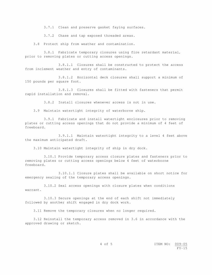
4 of 5 ITEM NO: 009-05 FY-15
3.7.1 Clean and preserve gasket faying surfaces. 3.7.2 Chase and tap exposed threaded areas. 3.8 Protect ship from weather and contamination. 3.8.1 Fabricate temporary closures using fire retardant material, prior to removing plates or cutting access openings. 3.8.1.1 Closures shall be constructed to protect the access from inclement weather and entry of contaminants. 3.8.1.2 Horizontal deck closures shall support a minimum of 150 pounds per square foot. 3.8.1.3 Closures shall be fitted with fasteners that permit rapid installation and removal. 3.8.2 Install closures whenever access is not in use. 3.9 Maintain watertight integrity of waterborne ship. 3.9.1 Fabricate and install watertight enclosures prior to removing plates or cutting access openings that do not provide a minimum of 4 feet of freeboard. 3.9.1.1 Maintain watertight integrity to a level 4 feet above the maximum anticipated draft. 3.10 Maintain watertight integrity of ship in dry dock. 3.10.1 Provide temporary access closure plates and fasteners prior to removing plates or cutting access openings below 4 feet of waterborne freeboard. 3.10.1.1 Closure plates shall be available on short notice for emergency sealing of the temporary access openings. 3.10.2 Seal access openings with closure plates when conditions warrant. 3.10.3 Secure openings at the end of each shift not immediately followed by another shift engaged in dry dock work. 3.11 Remove the temporary closures when no longer required. 3.12 Reinstall the temporary access removed in 3.6 in accordance with the approved drawing or sketch.

5 of 5 ITEM NO: 009-05 FY-15
3.12.1 Accomplish the requirements of 009-12 of 2.1 for installation and inspection of the access. 3.12.1.1 Accomplish nondestructive testing with acceptance criteria for: new welds, existing welds extending 3 inches beyond cutbacks, 24 inches of riveted joints within 12 inches of new welds, and repaired riveted joints including 12 inches either side of the repairs. Acceptance criteria for the welds adjacent to the cutbacks shall be limited to an absence of crack indications. 3.12.2 Install the bolted/riveted access. 3.12.2.1 Use new gasket material conforming to MIL-PRF-900 and fastener material conforming to MIL-DTL-1222, Grade 304. 3.12.2.2 Install new rivets for riveted access plates in accordance with 2.2. (V) "CHALK TEST" 3.13 Accomplish a chalk test on structural closure in way of temporary access. Chalk imprint shall be centered with 100-percent contact. 3.14 Accomplish the requirements of 009-25 of 2.1 for the cofferdam, vacuum box, air hose, or water hose test of each watertight/airtight closure. Allowable leakage: None. 4. NOTES: 4.1 None.


1 of 4 ITEM NO: 009-06 FY-15
NAVSEA STANDARD ITEM FY-15 ITEM NO: 009-06 DATE: 17 JAN 2013 CATEGORY: I 1. SCOPE: 1.1 Title: Maintaining Protection and Cleanliness from Non-Radioactive
Operations; accomplish 2. REFERENCES: 2.1 Standard Items 3. REQUIREMENTS: 3.1 Observe the following requirements, in addition to the specific requirements of the Job Order, for maintaining cleanliness of the ship, ship's equipment, components, and spaces for the duration of the availability. 3.1.1 Accomplish an inspection of the work area prior to installation of protective covering to identify the current condition of equipment, systems, and components, including any exposed cables, penetrations, stuffing tubes, bolted cover plates, and antennas. 3.1.1.1 Submit one legible copy, in hard copy or approved transferrable media, of a report listing results of the requirements of 3.1.1 to the SUPERVISOR. 3.2 Prevent contamination and damage of the ship's equipment, components, and spaces during contamination-producing operations. 3.2.1 Plug, blank, wrap, cover, seal, and mask equipment, components, cables, wireways, boots, and openings using fire retardant/water repellent material, and prevent entry of contaminants to components, systems and equipment. 3.2.1.1 Ensure plugging and blanking does not result in flooding or damage to ship's equipment. 3.2.1.2 Install Herculite or canvas covering conforming to A-A-55308, and/or fire retardant plywood conforming to Category 2, Type II, of MIL-L-19140, or other NAVSEA-approved fire retardant industrial protective material.

2 of 4 ITEM NO: 009-06 FY-15
3.2.2 Install fire retardant industrial filter material meeting the minimum requirements of UL 900 Class 1, non-fire contributing material, on the intake of supply and exhaust end of ventilation systems that will be in use. 3.2.2.1 Remove existing and install new filter or clean the filter material when air flow is restricted. (V) "VERIFY PROTECTIVE MEASURES" 3.2.3 All protective measures are to be in place prior to start of any contamination-producing operations and shall remain in place until the contamination-producing operations are complete. 3.2.4 Install double curtain baffles at the entrance of each access door where airborne contamination could occur during contamination-producing operations. Install a dirt collecting mat on the deck directly inside each door. The SUPERVISOR will select a maximum of 4 doors. Tag out doors not designated for access. 3.2.5 Temporary coverings shall not be removed during contamination-producing operations without permission of the SUPERVISOR. (V) "INSPECT PROTECTIVE COVERING" 3.3 Inspect the integrity of the protective covering at the beginning of each shift in which contamination-producing operations will be accomplished. Ensure that equipment and machinery have not been infiltrated by contaminants. Notify the SUPERVISOR immediately by verbal means, followed on the next work day in writing, if contamination or surface damage has occurred. Reseal to prevent further entry of contaminants or surface damage. 3.4 Maintain cleanliness of the work site, including bilges, free from accumulation of industrial debris caused by contractor and/or subcontractor employees on a continuous basis throughout the availability. Work spaces include those areas immediately under and adjacent, and those areas where service lines are run, and bilge areas in vicinity of the work site. 3.4.1 Cleaning shall be accomplished no later than at the end of each shift at a minimum, on a daily basis. 3.4.2 Remove and dispose of industrial debris from the ship at the end of each shift at a minimum, on a daily basis. 3.4.3 Vacuum cleaners shall be emptied of all debris at the end of each shift at a minimum, on a daily basis. 3.4.3.1 Use metal canister vacuum cleaners aboard the ship, except those used for regulated and controlled radiological and hazardous waste or hazardous material.

3 of 4 ITEM NO: 009-06 FY-15
3.4.3.2 Permanently and legibly mark each vacuum cleaner with a company name or unique identifier. 3.5 Accomplish a cleanliness inspection on a daily basis whenever work is in progress. The inspection shall be made jointly with the SUPERVISOR and the Commanding Officer's designated representative. During inspection the responsible party shall be assigned. A written report of any unclean work sites/spaces shall be prepared by the contractor and copies distributed to the SUPERVISOR and Commanding Officer's designated representative within 4 hours after completion of the inspection. The inspection report shall list the responsible activity (contractor, ship, etc.) for each unclean site/area. Unclean sites/areas determined as contractor responsible shall be immediately cleaned. 3.5.1 Accomplish inspections and reporting during the daily fire prevention and housekeeping inspections in accordance with 009-07 of 2.1. (V)(G) "FINAL CONTAMINATION/DAMAGE INSPECTION" 3.6 Remove protective covering installed in 3.2 upon completion of contamination-producing operations. Accomplish a final inspection of the work area to identify the presence of contamination and/or damage created by contamination-producing operations. Contamination/damage shall be documented on the inspection record. 3.7 Remove from the ship and dispose of debris and foreign matter generated as a result of work being accomplished at the end of each shift at a minimum, on a daily basis. Comply with the requirements of federal, state, and local laws, codes, ordinances, and regulations or as specified elsewhere in the Job Order. 4. NOTES: 4.1 Definitions: 4.1.1 Cleanliness means the removal of all industrial debris (industrial trash, waste material, weld rods/tips, fasteners, rags, lagging waste, job scrap, wire, litter, rubbish, etc.) at the end of each shift, leaving the areas broom clean and electronic spaces vacuum clean. Adjacent/surrounding machinery, equipment, etc., shall be cleaned free of all resulting debris. 4.1.2 Daily means at least once per every calendar day. 4.1.3 Non-radioactive contaminate-producing operations include but are not limited to: 4.1.3.1 Operations liable to produce particulates to become airborne during accomplishment of the work scope, i.e., abrasive blasting, mechanical cleaning, spray painting, hot work operations, and air blowdowns.

4 of 4 ITEM NO: 009-06 FY-15
4.1.3.2 Operations liable to produce fluid contamination of equipment as a result of external leakage of piping systems during testing. 4.1.3.3 Operations liable to produce fluid contamination of equipment as a result of external leakage of piping systems during waterjetting. 4.1.3.4 Operations liable to produce industrial debris such as, but not limited to, industrial trash, waste material, weld rods/tips, fasteners, rags, lagging waste, job scrap, wire, litter, rubbish, etc. 4.2 The SUPERVISOR will coordinate operation of ventilation systems, as requested by the contractor, to maintain a positive pressure within the vessel's envelope and to create an outward flow of air through crevices or around penetrations. 4.3 The cleanliness goal is to turn over all areas of the ship in the same condition or better as at beginning of the availability. 4.4 Ship's Force responsibility: 4.4.1 Ship's Force is responsible for dust that collects as a matter of course throughout the availability and for any Ship's Force job site maintenance including monitoring job sites being worked by intermediate maintenance activities, Alteration Installation Teams (AIT), and any contractor services that the ship has arranged. 4.4.2 Ship's Force is responsible to maintain cleanliness of their areas of responsibility broom clean at the end of each shift, on a daily basis. 4.4.3 Ship's Force will report cleanliness concerns to the SUPERVISOR for contractor responsible areas. 4.4.4 Ship's Force will work continually throughout the availability to keep bilges and other general areas of the ship clean where the Contractor is not working. 4.5 Ship's Force and the Contractor will familiarize each other with their scope of work (any other work being performed on board the ship not pursuant to contractor authorized work under the Job Order is considered Ship's Force work). The affected locations and aspects of the work and/or ship conditions (i.e., blasting, grinding, preservation, hot work, insulation removals, decking replacement, hydroblasting, weight tests, electrical cable replacement, etc.) will be identified. Each responsible party will clean site in locations where both parties will be working, on a daily basis. Communications must be continuous and active 2 ways. 4.6 Diligence in inspection will ensure that action is taken by the responsible party prior to any area becoming unsatisfactory.

1 of 14 ITEM NO: 009-07 FY-15
NAVSEA STANDARD ITEM
FY-15 ITEM NO: 009-07 DATE: 17 JAN 2013 CATEGORY: I 1. SCOPE: 1.1 Title: Confined Space Entry, Certification, Fire Prevention and
Housekeeping; accomplish 2. REFERENCES: 2.1 Standard Items 2.2 29 CFR Part 1915, Occupational Safety and Health Standards for
Shipyard Employment 2.3 29 CFR Part 1910.134, Occupational Safety and Health Standards,
Respiratory Protection 2.4 NFPA Standard 51B, Standard for Fire Prevention During Welding,
Cutting, and Other Hot Work 2.5 NFPA Standard 312, Standard for Fire Protection of Vessels During
Construction, Repair, and Lay-up 2.6 American Conference of Government Industrial Hygienists (ACGIH)
Threshold Limit Values for Chemical Substances and Physical Agents 2.7 NAVSEA OP-4, Ammunition and Explosives Safety Afloat 3. REQUIREMENTS: 3.1 Comply with the requirements of 2.2 through 2.5 and this item to determine whether or not an explosive or other dangerous atmosphere exists in tanks, spaces, and associated piping, including adjacent tanks, spaces, and piping aboard the ship and control hot work and entry to those spaces to preclude damage to the ship or injury to personnel during the accomplishment of this Job Order. 3.1.1 Submit one legible copy, in approved transferrable media, of a list of tanks or spaces to be opened or certified to the SUPERVISOR at least 24 hours prior to opening the tank or void.

2 of 14 ITEM NO: 009-07 FY-15
3.1.1.1 Comply with additional requirements of 009-88 of 2.1 when accomplishing work in Collection, Holding and Transfer (CHT) and Mogas tanks, spaces, or associated piping. 3.1.1.2 For fuel tanks or spaces that contain or have contained fuel, including F-76 and JP-5, in addition to the atmospheric testing required by 2.2, test for diesel fuel (CAS No. 68334-30-5; 68476-30-2; 68476-31-3; 68476-34-6, 77650-28-3) as total hydrocarbons in accordance with 2.6, and record total hydrocarbon test results on the Marine Chemist Certificate or competent person’s log of tests and inspections. 3.1.2 Provide initial and annual update training for Competent Persons by utilizing a National Fire Protection Association (NFPA) Certified Marine Chemist or NFPA Instructor. The length of the initial training class shall be at least 24 hours. Annual update training shall be at least 8 hours. 3.1.2.1 Maintain a current roster of designated Competent Person(s) and copies of certificates of completion for the training required in 3.1.2 for reference by the SUPERVISOR. Submit one legible copy, in approved transferrable media, of the specific documents when requested by the SUPERVISOR. 3.1.3 Post a copy of the Marine Chemist Certificate, Certified Industrial Hygienist's test/inspection record, or Competent Person's test/inspection record at each access to the affected space while work in the space is in progress. When requested, a copy of the MCC or test/inspection record shall also be delivered to a location designated by the SUPERVISOR. In the event that the space is found to be NOT SAFE FOR WORKERS or NOT SAFE FOR HOT WORK, the space shall be posted accordingly and other affected contractors, the SUPERVISOR and Ship’s Force shall be notified immediately. The posted copy shall be clearly visible and legible. 3.1.3.1 Initial certification of spaces that require a Certified MCC or Certified Industrial Hygienist's test/inspection record in support of work operations shall be effective until conditions change which would void the certificate or test/inspection record. A Competent Person shall conduct the same atmospheric testing as required on the MCC or Certified Industrial Hygienist's test/inspection record. 3.1.3.2 For those certified spaces which employees will enter, a Competent Person shall visually inspect, test and record each space certified as ENTER WITH RESTRICTIONS or SAFE FOR WORKERS as often as necessary, and as a minimum, prior to entry by employees on a daily basis. If a space is not to be entered on any given day, it is not required to be inspected and tested by a Competent Person. The initial MCC remains valid if conditions have not changed, unless noted on the MCC. 3.1.3.3 For those certified spaces affected by hot work, a Competent Person shall visually inspect, test, and record each space

3 of 14 ITEM NO: 009-07 FY-15
certified as SAFE FOR HOT WORK as often as necessary and, as a minimum, daily prior to commencement of hot work to ensure that conditions established by the certificate are maintained. When hot work is continuous, the affected spaces shall be visually inspected, tested, and recorded on a daily basis to maintain the SAFE FOR HOT WORK certification. 3.1.3.4 If a Competent Person finds that the conditions within a certified space fail to meet the applicable requirements for which it was certified, work in the space shall be stopped and may not be resumed until the space has been recertified by a Marine Chemist. 3.1.3.5 For those spaces where only Competent Person tests and inspections are required in accordance with 2.2, a Competent Person shall visually inspect and test each space as often as necessary and, as a minimum, daily prior to entry or commencement of hot work to ensure that conditions are safe. 3.1.3.6 After the Competent Person has determined initially that a space is safe for entry and finds subsequently that the conditions within the tested space fail to meet the requirements of 2.2, work shall be stopped until the conditions in the tested space are corrected, the space is retested, reinspected, and a new record of tests/inspections is recorded and posted. 3.1.4 Tank cleaning personnel shall be trained annually on safety practices to include a discussion of safety information found in Subparts A, B, and Section 1915.152 of Subpart I of 2.2. 3.1.5 Maintain a current roster of the names of the Shipyard/Plant Rescue Team Members, along with contractor certification that training requirements of Subpart B of 2.2 have been accomplished and are current for each Rescue Team Member, or documentation of arrangements made for an outside rescue team to respond promptly to a request for rescue service in a contractor facility. Submit one legible copy, in approved transferrable media, of the specific documents when requested by the SUPERVISOR. 3.1.5.1 At a naval facility, the Navy will respond. 3.1.6 Spaces that are determined to contain Immediately Dangerous to Life or Health (IDLH) atmospheres shall never be entered except for emergency rescue or for short duration for installation of ventilation equipment in accordance with 2.2 and 2.3. When entering IDLH spaces for the purpose of installing ventilation, notify the SUPERVISOR prior to entry. Notifications of rescue shall be made as soon as management becomes aware of such an event. 3.1.7 Confirm that all personnel have exited the space prior to closure of tanks, voids, and cofferdams. Designate one person to account for all personnel who may have entered the space.

4 of 14 ITEM NO: 009-07 FY-15
3.2 Provide a written notice for each job or separate area of hot work aboard ship. 3.2.1 The notice shall state a description of the work to be done, the specific location, to include compartment number, of the hot work, and compartments adjacent to decks, bulkheads, and similar structures upon which hot work is to be accomplished, the time hot work will commence, current gas-free status of the area (if required), the absence or existence of combustible material within 35 feet in any direction of the operation (or further, if affected by the operation), and if combustible material exists, what action shall be taken to protect the material from fire, the provision and assignment of a fire watch, and the affirmation that conditions at the work site (ventilation, temporary lighting, accesses) permit the fire watch(es) to have a clear view of and immediate access to all areas included in the fire watch. 3.2.2 The notice shall affirm that a suitable, fully-charged fire extinguisher shall be available at the job site and provide for an inspection of the area 30 minutes after completion of the hot work or the cessation of hot work at the job site unless the contractor's Hot Work Supervisor surveys the affected work area and determines that there is no further fire hazard as the final action to complete the notice. 3.2.3 The notice shall be signed by a supervisor specifically designated as responsible for coordination of the hot work and the fire watch requirement. 3.2.4 One copy of each notice shall be given to the SUPERVISOR when requested and one copy to the Commanding Officer's designated representative, and at a minimum, one copy of each notice shall also be conspicuously posted at the location where the hot work is being accomplished. 3.2.4.1 The notice to the Commanding Officer's designated representative shall precede the initiation of the actual hot work in order to permit the Commanding Officer to designate a member of the crew to observe the operation, if desired. 3.2.4.2 Deliver written notification of hot work planned Tuesday through Friday to the Commanding Officer's designated representative at least 30 minutes and not more than 24 hours preceding start of work. 3.2.4.3 Deliver written notification of hot work planned over a weekend or Monday following that weekend to the Commanding Officer's designated representative no later than 0900 on the Friday immediately preceding that weekend. 3.2.4.4 Deliver written notification of hot work planned on a federal holiday and on the day following the federal holiday to the Commanding Officer's designated representative no later than 0900 of the last working day preceding the federal holiday.

5 of 14 ITEM NO: 009-07 FY-15
3.2.4.5 The notice shall be effective for 24 hours unless a shorter period is specified in the contract or the gas-free status of the work area or system requires stopping the work. A new notice is required if work is interrupted due to loss of gas-free status. 3.3 Provide trained fire watches, at all affected areas where hot work is being accomplished. Provide fire extinguishing equipment as described in 2.2, 2.4, and 2.5. 3.3.1 The program utilized to train fire watches shall be in accordance with the requirements of 2.2 and 2.4, and include steps to be taken by the fire watch and hot work operator prior to accomplishment of hot work, proper selection and use of fire extinguishing equipment and other safety equipment, relationship between the fire watch and hot work operator, proper fire reporting procedures and other sounding of fire alarms, and reporting of fires to the ship's Quarterdeck. This training shall include theory and practical (hands-on) fire suppression techniques. This training shall be provided to all newly assigned fire watches, with annual updates provided to personnel. Provide visible means of identifying trained fire watches, i.e., badge, sticker, vest, etc. 3.3.1.1 Submit one legible copy, in approved transferrable media, of the training program when requested by the SUPERVISOR. 3.3.2 Each fire watch attending worker(s) accomplishing hot work shall be equipped with a fully-charged and operable fire extinguisher, have immediate access and an unobstructed view of the affected hot work area to which they are assigned and shall remain at the job site for 30 minutes from the time the hot work is completed unless the contractor's Hot Work Supervisor surveys the affected work area and determines that there is no further fire hazard. 3.3.2.1 The fire watch shall not accomplish other duties while hot work is in progress. 3.3.3 Where several workers are accomplishing hot work at one site, the fire watch shall have a clear view of and immediate access to each worker accomplishing hot work. 3.3.3.1 No more than 4 workers shall be attended by a single fire watch. 3.3.4 In cases in which hot material from hot work may involve more than one level, as in trunks, machinery spaces, and on scaffolding, a fire watch shall be stationed at each level unless positive means are available to prevent the spread or fall of hot material. 3.3.5 In cases where hot work is to be accomplished on a bulkhead or deck, combustible material shall be removed from the vicinity of the hot

6 of 14 ITEM NO: 009-07 FY-15
work on the opposite side of the bulkhead, overhead, or deck, and a fire watch shall be posted at each location. 3.3.5.1 If multiple blind compartments are involved in any hot work job, fire watches shall be posted simultaneously in each blind area. 3.3.6 Comply with the firefighting and fire prevention requirements of 2.7 prior to hot work operations in or adjacent to areas containing ammunition or explosives. 3.3.6.1 Hot work shall not be conducted during any logistics or maintenance movement of ammunition or explosives. 3.4 Locate oxygen, acetylene, fuel gas, toxic, oxygen depleting (OD) gas supply systems off the ship. Manifolds connected to pierside supply systems may be placed on board ships as long as they are located on a weather deck and equipped with a shutoff valve located on the pier. The pierside shutoff valve shall be in addition to the shutoff valve at the inlet to each portable outlet header required by 2.2. 3.4.1 Oxygen, acetylene, fuel gas, toxic, and OD gas supply systems shall be stored to prevent collisions by trucks, forklifts, falling objects, etc. 3.4.2 LOX tanks shall be staged in designated locations on the quay wall/pier to be determined jointly by the contractor, Ship's Force, and the SUPERVISOR. 3.4.3 When gas cylinders are in use on board ship, they shall be located on the weather decks or in a location determined jointly by the contractor, Ship's Force, and the SUPERVISOR and shall be secured in cylinder racks, and in an upright position. The number of in-use cylinders shall be limited to those which are required for work in progress and which have pressure regulators connected to the cylinder valves. On-board reserve gas cylinders shall not exceed one-half the number of in-use cylinders and shall be located in a remote area of the weather decks or in a location determined jointly by the contractor, Ship's Force, and the SUPERVISOR. Reserve acetylene cylinders shall be secured in an upright position. 3.4.4 When not in use, gas cylinders and manifolds on board shall have valves closed, lines disconnected, protective cover (cap) in place, and shall be secured. Acetylene cylinders shall be secured in cylinder racks and in an upright position. 3.5 Each fuel gas and oxygen hose must be positively identified by durable unique markings that include the company name at each end of the hose. If hoses are connected together, then each connection shall be positively identified by durable unique markings that include the company name.
7 of 14 ITEM NO: 009-07 FY-15
3.5.1 Unattended fuel gas and oxygen hose lines or torches are prohibited in confined spaces. 3.5.2 Unattended, charged fuel gas and oxygen hose lines or torches are prohibited in enclosed spaces for more than 15 minutes. 3.5.3 All fuel gas and oxygen hose lines shall be disconnected at the supply manifold at the end of each shift. 3.5.4 All disconnected fuel gas and oxygen hose lines shall be rolled back to the supply manifold or to open air to disconnect the torch; or extended fuel gas and oxygen hose lines shall not be reconnected at the supply manifold unless the lines were given a positive means of identification when they were first connected and the lines are tested using a drop test to ensure the integrity of fuel gas and oxygen burning system. Alternate procedures must be approved by the SUPERVISOR. 3.5.5 Upon completion of oxygen-fuel gas system hook-up, accomplish a pressure drop test to include the torch, hoses, and gages. 3.5.5.1 Apply pressure to the system. Back off pressure by turning off the valve supplying gases to the system. If the pressure on the gage drops, a leak in the system exists. If the pressure on the gage does not drop, the system is tight. 3.5.5.2 After applying pressure, wait 2 minutes to ensure pressure does not drop. 3.5.6 The use of gas hose splitters is prohibited. 3.6 Inert gas/oxygen depleting (OD) hoses must be positively identified by durable unique markings that include the company name at each end of the hose. 3.6.1 Unattended inert gas/OD hose lines or torches are prohibited in confined spaces. 3.6.2 Unattended, charged inert gas/OD hose lines or torches are prohibited in enclosed spaces for more than 15 minutes. 3.6.3 All inert gas/OD hose lines shall be disconnected at the supply manifold at the end of each shift. 3.6.4 All disconnected inert gas/OD hose lines shall be rolled back to the supply manifold or to open air to disconnect the torch; or extended inert gas/OD hose lines shall not be reconnected at the supply manifold unless the lines were given a positive means of identification when they were first connected and the lines are tested using a drop test to ensure the integrity of inert gas/OD systems. Alternate procedures must be approved by the SUPERVISOR.

8 of 14 ITEM NO: 009-07 FY-15
3.6.5 Upon completion of inert gas/OD gas system hook-up, accomplish a pressure drop test to include the torch, hoses, and gages. 3.6.5.1 Apply pressure to the system. Back off pressure by turning off the valve supplying gases to the system. If the pressure on the gage drops, a leak in the system exists. If the pressure on the gage does not drop, the system is tight. 3.6.5.2 After applying pressure, wait 2 minutes to ensure pressure does not drop. 3.6.6 The use of gas hose splitters is prohibited. 3.7 Use fire retardant materials aboard or immediately adjacent to the ship for staging, screening, temporary covers, shelters, deck covering, and ventilation ducts. Proper documentation of fire retardancy shall be available for review upon request. 3.7.1 Lumber, plywood, and staging boards, except that used for pallets, shall be fire retardant in accordance with Category Two, Type II, of MIL-L-19140. 3.7.2 Storage of material aboard ship shall be limited to that which is required for work in progress. Materials, trailers, temporary lights, flammable liquids, fueling of vehicles, and the rigging of hoses/welding leads/temporary lights aboard the ship shall comply with the following: Material, including that stowed in bins that are placed and held temporarily on hangar decks, well decks, or tank decks shall not exceed 8 feet in height. A 20-foot-wide lane shall be maintained the length of hangar decks to act as a fire break. Material shall occupy a deck space not to exceed 25-feet by 25-feet with adjacent 6-foot-wide aisles on each side for ready hose line access. 3.7.3 Prior to bringing equipment or working material aboard ship, its crating and packing shall be removed. If the equipment or material may be damaged during handling, the crating and packing shall be removed immediately after the equipment or working material is brought aboard and taken ashore for disposal. A small quantity of pallets may be staged in a location determined jointly by the contractor, Ship's Force, and the SUPERVISOR aboard ship for use in materials handling operations. 3.7.4 Trailers placed aboard the ship shall be equipped with an automatic sprinkler system designed to provide 0.1 GPM per square foot of floor area and an audible alarm that will sound outside the trailer when the sprinkler system is activated. Tool issue shacks or other walk-in enclosures placed aboard the ship shall be constructed of fire retardant material, provided with at least one fire extinguisher of appropriate size and class at each access. The enclosure shall be supported at least 10 inches above the deck.

9 of 14 ITEM NO: 009-07 FY-15
3.7.4.1 Smoke alarms, approved by Underwriter's Laboratory, shall be installed in enclosures and shall be audible outside the enclosures.
3.7.5 Flammable or combustible liquids with a flash point of 150 degrees Fahrenheit or less, including degreasers, solvents, and fuels, shall be kept in metal safety cans and shall not be left unattended. These liquids shall be limited to one day's supply for on board use. 3.7.6 Fueling of vehicles or transfer of fuel between containers shall be accomplished at designated sites on weather decks or in a location determined jointly by the contractor, Ship's Force, and the SUPERVISOR. Notify ship's Officer of the Deck prior to the fueling or transfer operation. When fuel is transferred between containers, the containers shall be bonded and grounded to prevent static discharge. 3.7.6.1 Provide a minimum of 2 dry chemical portable extinguishers, each with an Underwriter's Laboratory rating of at least 60-B:C at the fueling site.
3.7.7 Shipboard temporary ventilation systems used for exhausting toxic contaminants and/or flammable vapors shall be constructed so that ducting within confined and enclosed spaces is under negative pressure. 3.7.8 Brief Ship’s Force personnel on the procedures to rapidly secure temporary systems (e.g., air, electrical power, and ventilation) under their control. 3.7.9 Brief Ship’s Force personnel on the procedures to operate temporary firefighting systems, if installed. Provide written operating procedures/instructions to Ship’s Force on each type of firefighting system. 3.8 Accomplish temporary access requirements as follows: 3.8.1 Temporary access cuts may be made in fire zone boundaries provided they are equipped with fume-tight steel closures when installed. Boundary degradation by use of temporary access cuts or passage of service lines shall be permitted only upon granting of a written waiver by the SUPERVISOR, in conjunction with the Commanding Officer's designated representative, for a limited time. 3.8.1.1 Submit one legible copy, in approved transferrable media, of a record of boundary openings and their locations to the SUPERVISOR and one additional copy to the Commanding Officer's designated representative. Resubmit boundary opening data when any changes, additions, or deletions of boundary openings occur. 3.8.2 Ensure at least one unobstructed access on ships designed with 3 or fewer accesses to each main and auxiliary machinery space and at

10 of 14 ITEM NO: 009-07 FY-15
least 2 unobstructed accesses on ships designed with 4 or more accesses to each main and auxiliary machinery space. 3.8.3 Stage fire retardant material adjacent to the ship to provide for temporary closure of access cuts, hatches, and other hull penetrations created by contractor work (e.g., access cuts and open hatches due to running of temporary services). 3.9 Accomplish a fire prevention and housekeeping inspection on a daily basis whenever work is in progress. The inspection shall be made jointly with the SUPERVISOR and the Commanding Officer's designated representative. 3.9.1 Submit one legible copy, in approved transferrable media, of a written report of the discrepancies and corrective actions, using Attachment A, to the SUPERVISOR and the Commanding Officer's designated representative within 4 hours after completion of the inspection. 3.10 Determine fire zone boundaries as follows: 3.10.1 The SUPERVISOR, Ship's Force, and the contractor shall establish fire zone boundaries prior to start of production work. 3.10.1.1 For ships having fire zones by design, the designated bulkheads shall be used as fire zones. Ships under 600 feet in length that do not have fire zones by design shall have a minimum of 2 fire zone boundaries. Ships 600 feet and over in length that do not have fire zones by design shall have a minimum of 3 fire zone boundaries. 3.10.2 Fire zone boundaries shall be continuous through the vertical extent of the ship, from the keel up to the highest weather deck, excluding the superstructure. 3.10.2.1 For ships that have established fire zone boundaries that run from keel up through the superstructure, the fire zone boundaries as depicted on the ship's damage control diagrams shall be observed. 3.10.2.2 On aircraft carriers, provide for closing of hangar division doors in case of fire in the event division doors being repaired by the contractor are mechanically inoperative. As a minimum, rig chain falls to manually close doors in the event of fire. Exceptions shall be permitted only upon execution of a written waiver approved by the SUPERVISOR.
3.10.3 Indicate each fire zone by installing a sign adjacent to each entrance. Mark each sign with international orange tape. 3.10.3.1 Service line(s) shall not be run through fire zone boundaries unless quick disconnects are installed in temporary service lines within 10 feet of the opening, door, or closure. The quick disconnects shall be marked with international orange tape and be positively identified by a durable unique marking that includes the company name and employee(s) using

11 of 14 ITEM NO: 009-07 FY-15
the service line. All service line(s) must be able to be secured and pulled back within 3 minutes. Fuel gas/oxygen/compressed gas hoses, steam lines, hoses pressurized above 140 PSI, or hoses carrying hazardous/toxic/flammable materials shall not be run through fire zone boundaries unless expressly authorized in writing by the SUPERVISOR. Hose numbers or sizes shall not restrict free and easy access or closure of fire zone boundary doors. 3.11 Develop and implement a written fire safety and emergency fire response plan in accordance with 2.2. Review the plan with contractor employees and subcontractors. 3.12 Ensure access to temporary and Ship’s Force firefighting equipment is not obstructed or restricted.
3.13 Conduct a firefighting and fire prevention conference in conjunction with the arrival conference or no later than 5 calendar days after start of the availability for availabilities in excess of 30 days. This conference shall familiarize Ship’s Force with the contractor’s fire safety and fire response plan for fire prevention and firefighting and with the procedures that will be in use by the contractor and the region/installation or municipal fire and emergency services, as well as familiarize the contractor and the region/installation or municipal fire and emergency services with the ship arrangement, shipboard fire prevention, and firefighting systems, equipment, and organization, and familiarize all parties with the scope of work and aspects of the work or ship conditions that have significance in fire prevention and firefighting. 3.13.1 The conference shall specifically address the following matters: 3.13.1.1 Fire alarm and response procedures 3.13.1.2 Contractor firefighting capability and procedures 3.13.1.3 Region/installation or municipal fire and emergency services firefighting capability and procedures 3.13.1.4 Firefighting jurisdictional cognizance 3.13.1.5 Communication system for fire reporting and control or firefighting efforts 3.13.1.6 Shipboard arrangement including access routes, availability or firefighting systems (installed and temporary), and communication systems 3.13.1.7 Shipboard firefighting organization, systems, drills, and equipment 3.13.1.8 Ship, space, and equipment security consideration

12 of 14 ITEM NO: 009-07 FY-15
3.13.1.9 Compatibility of ship, contractor, and region/installation or municipal fire and emergency services firefighting equipment 3.13.1.10 Industrial work scope, including location of ship, and effect on firefighting systems, access, and communications 3.13.2 The firefighting and fire prevention conference shall include a table top fire drill. 3.14 A tour of the ship shall be conducted for Naval installation fire and emergency services/or municipal fire department personnel, the SUPERVISOR, Ship’s Force, and contractor key personnel assigned specific responsibilities during fires to familiarize personnel concerned with the ship’s normal access and anticipated condition while industrial work is in progress. 3.15 Provide a portable 300 KW diesel generator with associated cables, lugs/plugs to supply emergency power during transits to and from dry dock when ship’s emergency power cannot be used or anytime during the availability that the ship’s power is not available as an emergency back-up to installed shore power. 4. NOTES: 4.1 In addition to CHT and Mogas tanks, Hydrogen sulfide (H2S) may be found in AFFF, seawater, and firemain systems. 4.2 Booklet of General Plans and Tank Sounding Tables are available for review at the office of the SUPERVISOR. 4.3 A "quick disconnect" is a coupling or connecting device/system designed to permit easy and immediate separation of lines without the use of tools and to ensure the contents do not escape. 4.4 Shipboard fixed extinguishing systems such as Halon and CO2 are to be secured or isolated only at the discretion of the ship’s Commanding Officer or designated representative. Employees should be trained as required by 2.2 before entering/working in spaces with active shipboard fixed extinguishing systems.

ATTACHMENT A
Type Codes: 1-Housekeeping, 2-Fire Prevent./Fire Equipment, 3-Hot Work., 4-FZ Boundary, 5-Electrical, 6-compress gas/hoses/bottles/manifolds, 7-Scaffolding, 8-Egress/Exit, 9- Walking/Working Surfaces, 10-PPE, 11- Containment, 12-Unguarded/Edges/Holes/Openings/Fall Protection, 13-Confined/Enclosed Spaces, 14-Lines & Leads Hazards, 15-Equip. Adrift & Rollback, 16-Ventilation, 17-Machine guarding/hand tools, 18-Crane/Rigging, 19-Environmental & Hazardous Material/Communication, 20-Environmental protection, 21-General Safety 13 of 14 ITEM NO: 009-07 FY-15
ESH Discrepancy and Corrective Action Log
Ship name/hull number:
Location: Prime Contractor:
Date: Time:
No. Point of Contact
Date Corrected Location Discrepancy Corrective Action Type
Code
Fire Zone Boundaries
Attendees

ATTACHMENT A
14 of 14 ITEM NO: 009-07 FY-15
ESH DISCREPANCY AND CORRECTIVE ACTION LOG INSTRUCTIONS
1- Fire Zone Boundaries: List the designated Fire Zone Boundaries. 2- Attendees: List Company and or Command and names of personnel present for walk thru. 3- Ship Name/hull Number: Indicate ship name and hull number of the location of the walk thru. 4- Location: Indicate location where ship is moored or docked, i.e. name of contractor facility or pier at Naval Base or Station. 5- Prime Contractor: Indicate prime contractor who has the contract with the SUPERVISOR. 6- Date: Indicate date of walk thru being accomplished. 7- Time: Indicate start time (24 hour clock) of walk thru being accomplished. 8- No. (number): List sequentially, each discrepancy noted during the walk thru. Number will continue where the numbering left off the previous day, until the end of the
availability. 9- Point of Contact: Indicate Company/Command identified with the discrepancy. 10- Date Corrected: Date condition was corrected. If condition is not corrected, condition will be carried over to the next walk thru until condition is corrected. 11- Location: Indicate location of the condition, i.e. space number or frame number. 12- Discrepancy: Indicate condition that needs corrective action, be specific as necessary. 13- Corrective Action: Indicate corrective action taken to correct the condition and who is responsible for the corrective action. 14- Code: Indicate code, located at the bottom of ATTACHMENT A that condition can be grouped with, i.e. lines on deck causing trip hazard would use code 14- Lines and
Leads Hazards.

1 of 7 ITEM NO: 009-08 FY-15
NAVSEA STANDARD ITEM
FY-15 ITEM NO: 009-08 DATE: 07 NOV 2013 CATEGORY: I 1. SCOPE: 1.1 Title: Fire Protection at Contractor's Facility; accomplish 2. REFERENCES: 2.1 NFPA Standard 312, Standard for Fire Protection of Vessels During
Construction, Repair, and Lay-up 2.2 NFPA Standard 1962, Standard for the Care, Use, and Service Testing
of Fire Hose Including Couplings and Nozzles 2.3 29 CFR Part 1915, Occupational Safety and Health Standards for
Shipyard Employment 3. REQUIREMENTS: 3.1 Provide fire protection in accordance with the requirements of 2.1 through 2.3 and this item. 3.2 Primary fire protection equipment shall consist of: 3.2.1 Fire pumps capable of providing the gallons per minute (GPM) flow specified in Attachment A at 100 PSIG with 2-1/2 inch fire hoses to ensure that GPM flow in Attachment A is uninterrupted for the entire availability. Flow and pressure shall be measured at the connection point to the ship's fire main. 3.2.1.1 Verify by the Pitot tube method or an in-line flow meter that the water supply specified in Attachment A is available. Water flow tests shall be accomplished prior to availability start date, each time the vessel shifts berths, and annually thereafter should the contract extend beyond one year. 3.2.2 Lighting provided for the ship/berthing barges topside area in the vicinity of each gangway. The term "ship" as used herein is synonymous with, and has the same definition as the term "vessel" as defined in 2.3.

2 of 7 ITEM NO: 009-08 FY-15
3.2.3 Install a fire alarm system on the quarterdeck as designated by the SUPERVISOR, arranged to send a signal directly to a central station service, a remote station service, a cognizant fire department, a shipyard fire department, or a continuously manned location within the shipyard where trained operators can take immediate action to transmit an alarm. 3.2.3.1 Test the fire alarm system daily to ensure its reliability. Repair or replace defective or inoperative alarms immediately. 3.2.3.2 Fire alarm devices placed aboard ship shall be either a fire alarm pull box or a non-dial telephone. 3.2.3.3 In addition, place a telephone on the quarterdeck as an alternate means of calling the cognizant fire department, shipyard fire department, or a continuously manned location within the shipyard where trained operators can take immediate action to transmit an alarm. 3.3 When the ship's fire main is out of service, temporary primary fire protection shall consist of: 3.3.1 Fire pumps capable of providing the gallons per minute (GPM) flow specified in Attachment A at 100 PSIG with 2-1/2 inch hoses to ensure that GPM flow in Attachment A is uninterrupted for the entire availability. Flow and pressure shall be measured at the connection point to the temporary hose valve manifold stations. 3.3.2 Two and one-half inch fire hose and hose valve manifolds on the vessel and dry dock or marine railway so that all parts of the vessel and dry dock or marine railway can be reached by at least 2, one and one-half inch or one and three-quarter inch 100-foot hoses. The 100-foot hoses shall be pre-connected and faked on racks nearby. 3.3.3 The components of the temporary primary firefighting system shall be inventoried and inspected prior to flooding the dock. Provide a copy of the inventory list and inspection results to the SUPERVISOR upon request. 3.3.4 Conduct final inspection and flow test of the temporary primary fire protection systems required in 3.3.1 and 3.3.2 prior to the ship’s firefighting systems or equipment being disabled. 3.4 Emergency fire protection equipment, in addition to that required by 3.2 or 3.3, shall consist of: 3.4.1 Fire pumps capable of providing 500 GPM at 100 PSIG to hose valve manifolds located on the vessel. Flow and pressure shall be measured at the manifolds. 3.4.2 Two and one-half inch fire hoses and hose valve manifolds on the vessel and dry dock or marine railway so that all parts of the vessel and

3 of 7 ITEM NO: 009-08 FY-15
dry dock or marine railway can be reached by at least 2, one and one-half inch or one and three-quarter inch 100 foot hoses. The 100 foot hoses and nozzles shall be pre-connected and faked on racks nearby. 3.4.2.1 The manifold stations shall be clearly identified, with sources of water and operating instructions. 3.4.2.2 Emergency fire protection shall be provided in the areas prior to placing any fire main section out of commission. 3.4.3 Water supply shall be available within 3 minutes of loss of primary source of fire main flow/pressure. 3.4.4 Emergency lighting and power, other than existing ship's emergency backup, shall be available for emergency lighting throughout the ship/barge and emergency devices using a separate source of energy or power line. 3.4.5 The components of the emergency fire protection equipment shall be inventoried and inspected prior to flooding the dock. Provide a copy of the inventory list and inspection results to the SUPERVISOR upon request. 3.4.6 Conduct final inspection and flow test of the emergency fire protection equipment required in 3.4.1 and 3.4.2 prior to the ship’s firefighting systems or equipment being disabled. 3.5 Primary, temporary primary, and emergency fire protection equipment shall consist of: 3.5.1 Fire hoses equipped with one and one-half inch combination straight stream and spray pattern nozzle. Charged hoses shall have recirculation capability which will prevent freezing of water in each hose. 3.5.2 Fire hoses shall be inspected and service-tested in accordance with 2.2 within 90 days before being placed in service for the first time and at least annually thereafter. 3.5.3 Portable communication devices shall be provided for use during firefighting operations between site and fire and contractor's key control center. 3.5.4 Portable lighting devices shall be in place to assist in firefighting operation when normal and emergency shipboard power fails. 3.5.5 Emergency backup support equipment (crane, forklift, trucks, pumps) to assist in securing or providing temporary services shall be provided. 3.5.6 Dewatering equipment (100 GPM minimum).

4 of 7 ITEM NO: 009-08 FY-15
3.5.7 Portable fire pumps capable of a total of 500 GPM at 100 PSIG on board ship during berth shifts, including transits to and from dry dock, when ship's system cannot be used. 3.5.8 Install gages at connection to the ship's fire main and on all temporary and emergency fire main manifolds, and ensure that 100 PSIG is maintained at each gage uninterrupted for the entire availability. 3.6 Maintain available for review, prior to commencement of work, a fire safety and fire response plan meeting the requirements of 2.3. In addition to the requirements of 2.3, the plan shall identify: 3.6.1 The integrated fire protection system which will be in effect during the performance of the Job Order. 3.6.2 Total fire prevention program used, along with the types and frequency of tests of equipment and devices. 3.6.3 Detailed communication links (telephones, drop boxes, alarms, horns) location, testing interval, and their interface with municipal systems. 3.6.4 Normal and emergency sources of electric power, firefighting water and lighting, testing interval, and their interface with municipal systems. 3.6.5 The location of all the normal and emergency backup support equipment to be used in support when combating a fire, and the equipment's testing cycle. 3.6.6 The shipyard organization to be used and their: 3.6.6.1 Designation and responsibility for all shifts 3.6.6.2 Training 3.6.6.3 Anticipated response times 3.6.6.4 Interface with municipal units 3.6.7 The general procedures directing contractor employees on: 3.6.7.1 Fire reporting 3.6.7.2 Fire responses 3.6.7.3 Firefighting actions 3.6.7.4 Prolonged firefighting responsibilities

5 of 7 ITEM NO: 009-08 FY-15
3.6.8 The frequency testing cycle of the fire protection system. 3.7 The requirements of 3.6.7.1 shall be posted on the quarterdeck. 3.8 Ensure access to temporary and Ship’s Force firefighting equipment is not obstructed or restricted. 3.9 Brief Ship’s Force personnel on the procedures to rapidly secure temporary systems (e.g., air, electrical power, and ventilation) under their control. 4. NOTES: 4.1 None.


6 of 7 ITEM NO: 009-08 FY-15
ATTACHMENT A FIRE PROTECTION WATER SUPPLY REQUIREMENTS
SHIP TYPE FLOW (GPM) * AD Destroyer Tender 1,500 ADG Degaussing Ship 500 AE Ammunition Ship 1,500 AF Store Ship 1,500 AFS Combat Store Ship 1,500 AG Miscellaneous Auxiliary Ship 1,500 AGEH Hydrofoil Research Ship 500 AGF Miscellaneous Flagship 2,000 AGFF Frigate Research Ship 1,000 AGM Missile Range Instrumentation Ship 1,500 AGMR Major Communications Relay Ship 1,500 AGOR Oceanographic Research Ship 500 AGP Gunboat Support Ship 2,000 AGS Surveying Ship 1,000 AH Hospital Ship 1,000 AK Cargo Ship 1,500 AKS Store Issue Ship 1,500 AKR Vehicle Cargo Ship 1,500 ANL Net Laying Ship 500 AO Oiler 1,500 AOE Fast Combat Support Ship 1,500 AOG Gasoline Tanker 1,000 AOR Fleet Replenishment Oiler 1,500 AP Transport Ship 1,000 APB Self-propelled Barracks Ship 500 AR Repair Ship 1,500 ARB Battle Damage Repair Ship 500 ARC Cable Repair and Laying Ship 1,000 ARG Internal Combustion Engine Repair Ship 1,500 ARL Landing Craft Repair Ship 1,000 ARS Salvage Ship 500 ARSD Salvage Lifting Ship 500 ARST Salvage Tender 1,000 ARVA Aircraft Repair Ship 1,000 ARVE Aircraft Engine Ship 1,000 ARVH Helicopter Tender 1,500 AS Submarine Tender 1,500 ASR Submarine Rescue Ship 600 ATA Ocean Tug 500 ATF Ocean Tug Fleet 500 ATS Salvage and Rescue Tug 500 AVM Guided Missile Ship 1,500 CV, CVN Aircraft Carrier 3,000 CG Guided Missile Cruiser 1,000

7 of 7 ITEM NO: 009-08 FY-15
ATTACHMENT A FIRE PROTECTION WATER SUPPLY REQUIREMENTS (Con't)
SHIP TYPE FLOW (GPM) * DDG Guided Missile Destroyer 1,000 FFG Guided Missile Frigate 1,000 IX Unclassified Miscellaneous 1,500 LCC Amphibious Command Ship 1,000 LCS Littoral Combat Ship 1,000 LHA Amphibious Assault Ship 2,500 ** LHD Amphibious Assault Ship 2,500 LKA Amphibious Cargo Ship 1,500 LPD Amphibious Transport Dock 1,500 *** LSD Landing Ship Dock 2,000 *** YRB Repair and Berthing Barge 500 YRBM Repair, Berthing and Messing Barge 500 YRBL Repair, Berthing and Messing Barge (large) 500 LST Landing Ship Tank 1,500 *** MCM Mine Counter Measures Ship 750 PC Patrol Coastal 500 PCH Hydrofoil Patrol Craft 500 PG Patrol Combatants 500 PGH Hydrofoil Gunboat 500 * All flows are from the pier or dry dock outlet and are available at
adequate residual pressures from those systems in compliance with present design criteria for dry docks and piers as reflected in NAVFAC design manuals (UFC 4-213-10, UFC 4-213-12, UFC 4-150-01, UFC 4-150-02, and UFC 4-150-06).
** Includes supply to operate 2 hangar sprinkler groups and 2, 2-1/2-inch hoselines. *** Includes supply to operate one sprinkler group and 2, 2-1/2-inch hoses.

1 of 3 ITEM NO: 009-09 FY-15
NAVSEA STANDARD ITEM
FY-15 ITEM NO: 009-09 DATE: 06 JAN 2014 CATEGORY: II 1. SCOPE: 1.1 Title: Process Control Procedure (PCP); provide and accomplish 2. REFERENCES: 2.1 None. 3. REQUIREMENTS: 3.1 Submit one legible copy of each PCP, in approved transferrable media, to the SUPERVISOR for approval. For planned availabilities, submission shall be no later than 14 working days prior to start of the required process, or as otherwise approved by the SUPERVISOR for emergent work. Unless otherwise specified, Attachment A shall be used as the format for PCP development, ensuring each element is contained within its respective section. The procedure shall contain the following minimum information: 3.1.1 Contractor's name and address. 3.1.2 Process title, number, and date developed. 3.1.3 Description of process, including critical factors which have direct bearing on the process quality and safety. 3.1.4 Qualification requirements for the personnel performing the work. 3.1.5 Inspection and documentation forms. 3.1.6 Acceptance and rejection criteria. 3.1.7 The method utilized to ensure personnel accomplishing the procedure have direct knowledge of the requirements prior to beginning work. A copy of the procedure shall be at the work site during the performance of work. 3.1.8 The method utilized to control the procedure.

2 of 3 ITEM NO: 009-09 FY-15
3.1.9 Identification of hazardous materials which will be used in the process or hazardous waste that will be generated by the accomplishment of the process and the methodology which will be utilized to minimize the quantity of these materials which will require control and disposal. State if no hazardous material or waste is generated or used. 3.1.10 Approval signature and title of the contractor's representative, date of submission, and scheduled start date of PCP. 3.1.11 Government notification (G) for start of procedure (3.4). 3.2 Submit updated or changed procedures to the SUPERVISOR at least 3 working days prior to implementation. 3.3 Participate in a joint Ship's Force and SUPERVISOR personnel safety brief, prior to start of PCP. 3.3.1 For SI 009-88 PCP’s, the safety brief shall include a hand-over-hand inspection and verification of the tagged-out piping/mechanical/ electrical system. (V)(G) "START OF PROCEDURE" 3.4 Provide notification to the SUPERVISOR when ready to start the PCP. 3.4.1 Verify the PCP is approved. 3.4.2 Verify necessary parts and equipment are on hand to start work. 3.4.3 Attend/verify job briefing conducted prior to start of work. 3.5 Accomplish the requirements of the approved PCP. 3.6 Ensure completed process control documentation provides a record of the data required to control and determine the satisfactory completion of the process. 3.6.1 Submit one legible copy, in hard copy or approved transferrable media, of the completed documentation to the SUPERVISOR no later than 24 hours after completion of the PCP. 4. NOTES: 4.1 None.

3 of 3 ITEM NO: 009-09 FY-15
ATTACHMENT A Process Control Procedure (PCP) Checklist
Section One - Identification • Include the Process Title and Procedure Number with revision, as
appropriate. • List the Ship’s name, Work Item and paragraph that the PCP fulfills. • Include contractor/subcontractor's name and address. • Include space for the Approval Signature and title of the contractor's
representative. Include spaces for the Date Developed and Date of Submission.
• If submitting a previously approved PCP, include the previous Government approval letter (if appropriate) and attach a letter of intent to use the PCP with the updated information required by this section. A revision of Section 1 of the previously approved PCP is not required.
Section 2 - Personnel Qualifications • List the qualifications of the personnel performing the work. • Include a statement that a briefing will be conducted prior to beginning
work to ensure personnel have direct knowledge of the requirements of the procedure and the safety requirements of the job.
Section 3 - Process Description • List any specialized or critical equipment needed to perform the work. • List any specialized or critical personnel safety equipment. • State that Government Notification (V)(G) will be made at the start of the process as applicable. • Describe the process as related to the sequence of work. • List the acceptance and rejection criteria used for determining
satisfactory process completion. • Provide inspections required for the process, to include (V), (I), and (G)
symbols invoked by the Work Item applicable to the process. • Provide inspection and documentation forms applicable to the process. • Include a statement that a copy of the PCP will be provided at the work
site during the performance of the work. | Section 4 - Hazardous Material • State if no hazardous material/waste will be used or generated. • Identify any hazardous material/waste used or generated during the
performance of work. Include a Material Safety Data Sheet for each hazardous material that will be used aboard ship.
• Describe the methodology to limit the quantity that will require control. • Describe the methods of the disposal of hazardous material or hazardous
waste.


1 of 6 ITEM NO: 009-10 FY-15
NAVSEA STANDARD ITEM FY-15 ITEM NO: 009-10 DATE: 29 JUL 2011 CATEGORY: I 1. SCOPE: 1.1 Title: Shipboard Asbestos-Containing Material (ACM); control 2. REFERENCES: 2.1 29 CFR 1915.1001, Occupational Safety and Health Standards for
Shipyard Employment, Asbestos 2.2 MIL-STD-769, Thermal Insulation Requirements for Machinery and Piping 2.3 40 CFR Part 61, National Emission Standards for Hazardous Air
Pollutants 3. REQUIREMENTS: 3.1 Consider insulation, lagging, deck tile, underlayment, gasket, shipboard cabling (see 4.2), and mastic to be asbestos-containing material (ACM) until it can be established by laboratory analysis, or other reliable method(s), that the material does not contain asbestos, in accordance with 2.1. This includes reusable covers as defined in 2.2. 3.2 Apply the following requirements for the removal, disturbance, or disposal of all asbestos containing materials during the initial monitoring, daily monitoring, and control of ACM throughout the work areas, and to Class I, II, III, or IV activities as defined in 2.1. 3.2.1 Ensure that responsibilities for personnel safety and environmental control of ACM existing or damaged during accomplishment of work are assigned and implemented. 3.2.2 Maintain written substantiation of the credentials of the Qualified Person. 3.2.2.1 The Qualified Person shall take airborne samples, monitor work practices, maintain daily logs, conduct on-site inspections, set up regulated areas, be capable of specifying the necessary protection and precautions to be taken during work with ACM, and accomplish the other requirements in accordance with Class I, II, III, and IV activities as defined

2 of 6 ITEM NO: 009-10 FY-15
in 2.1. The Qualified person shall have successfully completed an initial EPA or state approved 40-hour Asbestos Supervisor's Course and annual refreshers. 3.2.2.2 Individuals performing airborne asbestos analysis must have successfully completed a NIOSH 582 course or equivalent and be rated proficient in either AIHA's PAT program or AAR program. Persons performing analysis of fiber type on bulk samples must have completed a McCrone Course in analysis of bulk asbestos samples and be rated proficient in either the NVLAP or AIHA's asbestos program. 3.2.2.3 Copies of certifications, licenses, notifications (such as advance notification to OSHA of new or modified control technology to be used to reduce exposure), and other documentation required by federal, state, and local regulatory authorities, shall be maintained at the worksite. 3.2.3 Identify removal routes and steps to be taken to protect insulation, repair damaged insulation, and to avoid asbestos contamination along those routes and obtain SUPERVISOR approval prior to proceeding. 3.2.4 Submit one legible copy, in approved transferrable media, of notifications made to regulatory authority, regarding ACM removal, to the SUPERVISOR within 2 working days of providing such notices to the regulatory authority. 3.2.5 Submit a written notice to the SUPERVISOR and to the Commanding Officer's designated representative, and post at the Ship's Quarterdeck or other designated location for each job or separate area of ACM removed or damaged aboard ship where there may be ACM at least 4 hours, but not more than 24 hours, prior to the start of work. The notice shall contain the following information: 3.2.5.1 Ship's name and hull number 3.2.5.2 Work Item number 3.2.5.3 Compartment 3.2.5.4 Class of activity and type of insulation, lagging, deck tile, underlayment, and mastic, i.e., ACM or possible ACM (provide basis for determination) 3.2.5.5 Date and time to start to work 3.2.5.6 Deliver notification for work planned over a weekend or Monday following that weekend to the Commanding Officer's designated representative no later than 0900 on the Friday immediately preceding that weekend. 3.2.5.7 Deliver notification of work planned on a federal holiday and on the day following the federal holiday to the Commanding

3 of 6 ITEM NO: 009-10 FY-15
Officer's designated representative no later than 0900 of the last working day preceding the federal holiday. 3.2.6 Personnel accomplishing ACM work shall have a direct knowledge of the requirements of this procedure prior to beginning work. All training shall be under the direct supervision of a Qualified Person. 3.2.7 Monitor the affected areas daily to ensure compliance with 2.1. Monitoring shall include adjacent spaces to ensure the work area containments and work practices are effective. Results of surveillance shall be documented and the documentation shall be provided to the SUPERVISOR. 3.2.8 Submit one legible copy, in approved transferrable media, of a list of regulated areas, decontamination areas, and engineering controls to be established in accordance with 2.1, to the SUPERVISOR. 3.2.8.1 Identify configuration of critical barriers or isolation methods. 3.2.8.2 Identify location/configuration of decontamination areas, including the equipment room, shower (if necessary), and clean change room. 3.2.8.3 Identify ventilation and filtration requirements, including the negative pressure enclosure(s) if necessary. 3.2.9 Isolate or blank the ship`s ventilation systems in work areas to prevent asbestos contamination. 3.3 Post prominent caution signs as required by 2.1 outside of affected areas. 3.3.1 In addition to caution signs required by 2.1, provide danger signs at the entrance to affected areas. 3.3.1.1 Danger signs shall be 14 inches by 20 inches and be painted black and red for the top 5 inches and white for the remaining 9 inches. 3.3.1.2 The lettering shall be as follows with 3-inch minimum letters with an oval ring around them for the first line and one-inch minimum letters for the remaining lines:

4 of 6 ITEM NO: 009-10 FY-15
Background Black Ring White Letters White Background Red
Letters Black
Background White
3.4 Monitor work areas. 3.4.1 Determine areas of airborne concentrations and potential personnel exposure to airborne asbestos fibers in accordance with the requirements of 2.1. 3.4.2 Take air samples and monitor regulated areas in the vicinity of access openings that are not tightly secured. 3.4.2.1 If the airborne concentration of asbestos fibers is at, or exceeds, 0.1 fiber, longer than 5 micrometers, per cubic centimeter of air, corrective action shall be taken to reduce the concentration to less than 0.1 fiber, longer than 5 micrometers, per cubic centimeter of air. 3.5 Accomplish ACM removal as follows: 3.5.1 Secure and tag out ventilation systems securing the work area. 3.5.1.1 Blank ventilation systems to prevent contamination of the ventilation systems and other compartments. 3.5.2 Air discharged to the environment from any containment zone shall have passed through a HEPA filter and otherwise conform to 2.3. A negative pressure will be maintained in the containment area where possible. 3.5.3 Remove materials which may contain ACM, using wet work practices and engineering controls that will minimize airborne contamination in and adjacent to the work area. 3.5.3.1 Removal tools and work practices shall minimize the generation of airborne contamination and the deposit of ACM in the work area. 3.5.3.2 Equip vacuum cleaners used to help prevent the dispersion of asbestos fibers with HEPA filters. 3.5.3.3 Clear the work area of loose ACM, including ACM dust, prior to returning the area to normal status.
DANGE
ASBESTOS
CANCER AND LUNG DISEASE HAZARD
AUTHORIZED PERSONNEL ONLY RESPIRATORS AND PROTECTIVE
CLOTHING ARE REQUIRED IN THIS AREA

5 of 6 ITEM NO: 009-10 FY-15
3.5.4 Contain edges of insulation exposed by removal operations by cutting the exposed surface true and square and sealing the surface. Encapsulate exposed ACM surfaces with insulating cement conforming to ASTM C 195. 3.6 Dispose of ACM by bag method described below: 3.6.1 Collect and dispose of ACM waste, scrap, debris, and special clothing consigned for disposal, which may produce airborne concentrations of asbestos fibers, in sealed, impermeable polyethylene bags (minimum thickness, 6 mils). Prior to placing in bags, asbestos waste shall be wet down to reduce airborne concentrations of asbestos fibers. 3.6.2 Bag ACM scrap, debris, and waste at the worksite. 3.6.3 ACM shall be placed in sealed, 6-mil or heavier, impermeable polyethylene bags before removal from the work area. Pieces of insulation too large to fit into bags shall be encased in 6-mil, or heavier polyethylene film with edges sealed with tape conforming to MIL-C-20079. 3.6.4 Vacuum outer surfaces of bags containing ACM in affected areas immediately after removal from and adjacent to the worksite. 3.6.5 Place the ACM waste while wet in leak-tight double bags. 3.6.6 Affix a danger label, in accordance with 2.3, to each bag prior to removal from affected areas. Label shall read as follows: DANGER CONTAINS ASBESTOS FIBERS AVOID CREATING DUST CANCER AND LUNG DISEASE HAZARD 3.6.7 Affix a legible label to each bag stating the contractor's name, the name of the ship the asbestos was removed from, the name of the facility where the work was performed and date of the removal. The label shall be in permanent waterproof marking. 3.6.8 Dispose of bags containing ACM waste in accordance with applicable federal, state, and local regulations. Provide a copy of the completed Waste Shipment Record to the SUPERVISOR within 15 working days after initial shipment. 3.7 Monitor the area for asbestos upon completion of work and after cleanup. 3.7.1 The airborne concentration of asbestos fibers after work and cleanup shall be less than 0.1 fiber, longer than 5 micrometers, per cubic centimeter of air on an 8-hour, time-weighted average basis. The workspace shall not be released for entry of unprotected personnel until verification

6 of 6 ITEM NO: 009-10 FY-15
has been provided to the SUPERVISOR that the airborne level of asbestos is less than the 0.1 fiber level. 3.7.1.1 Submit one legible copy, in approved transferrable media, of the lab analysis listing results of air monitoring certifying the area to be less than 0.1 asbestos fiber longer than 5 micrometers per cubic centimeter of air, to the SUPERVISOR. 3.8 Remove ACM from salvage or scrap equipment, piping, and structural components prior to delivery to the GOVERNMENT. 4. NOTES: 4.1 See additional notification requirements of NAVSEA Standard Item 009-01. 4.2 Shipboard cabling as used in 3.1 refers to all shipboard cabling, with the exception of low smoke, coaxial cables, and lamp cord cabling. 4.3 The following ACB circuit breakers listed by manufacturer contain non-friable asbestos arc chutes: 4.3.1 SPD, ITE, ITE/Gould: 640R, 900RC, 901R, 1600R, 1600HR, 1600HRC, 2000HR, 2000RC (450V), 2601R, 2801R, 3200HR, 4000HR. 4.3.2 General Electric: All types. 4.3.3 Westinghouse: All DBN types. 4.4 The term "asbestos fibers" is defined in 2.1. 4.5 Salvage - Property has some value in excess of its basic material content, but repair or rehabilitation to use for the originally intended purpose is clearly impractical. Repair for any use would exceed 65 percent of the original acquisition cost. 4.6 Scrap - Material that has no value except for its basic material content.

1 of 3 ITEM NO: 009-11 FY-15
NAVSEA STANDARD ITEM FY-15 ITEM NO: 009-11 DATE: 17 JAN 2013 CATEGORY: II 1. SCOPE: 1.1 Title: Insulation and Lagging Requirements; accomplish 2. REFERENCES: 2.1 Standard Items 2.2 MIL-STD-769, Thermal Insulation Requirements for Machinery and Piping 2.3 804-5959212, Surface Ship Machinery Insulation - Installation Details 2.4 804-5959214, Piping Insulation - Installation Details 2.5 804-5773931, Insulation for Compartments, Acoustic and Thermal
Installation Details 2.6 804-5773932, Insulation for Ducts, Acoustic and Thermal,
Installation Details 2.7 803-5184182, Insulation, Passive Fire Protection - Installation
Details 2.8 46 CFR Part 164, Materials 2.9 S4823-C-3160935, Fasteners for Insulation and Lagging 3. REQUIREMENTS: 3.1 Install new insulation, lagging, and reusable covers in accordance with 2.2 through 2.7, and the following: 3.1.1 Use of elastomeric foam conforming to MIL-P-15280 and polyphosphazene conforming to MIL-I-24703 is not permitted. 3.1.2 MIL-PRF-22344 insulation shall not be installed on hot piping above one-inch nominal pipe size (nps) and shall be installed only on piping with a vertical orientation or in low traffic areas.

2 of 3 ITEM NO: 009-11 FY-15
3.1.3 Install Electric Boat Specification No. 4013 Anti-Sweat and Refrigerant Insulation Systems (EB Spec. 4013 or equal) on anti-sweat and refrigeration piping systems that have an operating temperature of minus 20 degrees to 180 degrees Fahrenheit. 3.1.3.1 Install with adhesive conforming to MIL-A-24179. 3.1.3.2 Install rewettable fibrous glass cloth lagging conforming to MIL-C-20079, Type I, Class 6 or 8, in high traffic areas. In addition to the requirements of MIL-C-20079, rewettable lagging shall meet the requirements of Section 164.009-3 of 2.8, unless otherwise approved by NAVSEA. 3.1.4 Utilize Polyimide foam insulation conforming to DOD-I-24688, Type I, for piping and machinery systems other than systems listed in 3.1.3, and with a maximum operating temperature of 400 degrees Fahrenheit. 3.1.5 Accomplish the requirements of 009-12 of 2.1. 3.1.6 Accomplish the requirements of 009-32 of 2.1 for surfaces to be insulated with the exception of non-ferrous and corrosion resistant steel (CRES) piping. 3.1.7 Secure reusable covers using snap fasteners or laced with copper, brass or soft steel galvanized wire through hooks or rings in accordance with 2.9. 3.1.7.1 Stamp the surface of the lacing washers, piece 200 of 2.8, on the reusable cover with one quarter inch high letters, NO AB, located close to the outer edge of the washer and visible when the reusable cover is installed. 3.2 Accomplish the requirements of 009-32 of 2.1 for new insulation, lagging, and reusable covers to match surrounding areas. 4. NOTES: 4.1 Known source for EB Spec. 4013: General Dynamics Company Dept. 447 Material Services Attn: K. Hamler 75 Eastern Point Road Groton, CT 06340-4899 Tel: 860-433-2373

3 of 3 ITEM NO: 009-11 FY-15
4.2 Known sources for rewettable fibrous glass cloth lagging: BGF Industries, Inc. Alpha Associates 3802 Robert Porcher Way Two Amboy Avenue Greensboro, NC 27410 Woodbridge, NJ 07095 Tel: 800-925-1961 Tel: 732-634-5700


1 of 18 ITEM NO: 009-12 FY-15
NAVSEA STANDARD ITEM
FY-15 ITEM NO: 009-12 DATE: 07 NOV 2013 CATEGORY: II 1. SCOPE: 1.1 Title: Welding, Fabrication, and Inspection Requirements; accomplish 2. REFERENCES: 2.1 Standard Items 2.2 MIL-STD-1689, Fabrication, Welding, and Inspection of Ships Structure 2.3 American Bureau of Shipping (ABS) Rules for Building and Classing
Steel Vessels 2.4 0900-LP-060-4010, Fabrication, Welding, and Inspection of Metal Boat
and Craft Hulls 2.5 T9074-AQ-GIB-010/248, Requirements for Welding and Brazing Procedure
and Performance Qualification 2.6 0900-LP-001-7000, Fabrication and Inspection of Brazed Piping Systems 2.7 S9074-AR-GIB-010/278, Requirements for Fabrication Welding and
Inspection, and Casting Inspection and Repair for Machinery, Piping, and Pressure Vessels
2.8 MIL-STD-22, Welded Joint Design 2.9 MIL-STD-2035, Nondestructive Testing Acceptance Criteria 2.10 T9074-AS-GIB-010/271, Requirements for Nondestructive Testing Methods 2.11 DOD-STD-2185, Requirements for Repair and Straightening of Bronze
Naval Ship Propellers 2.12 S9221-C1-GTP-010/020, Repair and Overhaul, Main Propulsion Boilers 2.13 S9AAO-AB-GOS-010, General Specifications for Overhaul of Surface
Ships (GSO) 2.14 MIL-STD-2191, Repair, Welding, Weld Cladding, Straightening, and Cold
Rolling of Main Propulsion Shafting

2 of 18 ITEM NO: 009-12 FY-15
2.15 S9FFG-AG-SRM-010, Superstructure Cracking Repair; FFG7 Class, Ship
Repair Manual 2.16 DM 10-612, SERMC, FFG7 Class Aluminum Deckhouse Critical Welds and
Critical Weld Regions 2.17 S9CGO-BP-SRM-010/CG-47CL, Technical Manual for CG-47 Class,
Superstructure Cracking Repair 2.18 DM 10-623, SERMC, Quality Assurance Requirements for Welding 5XXX
Series Aluminum Structures for CG-47 Class
3. REQUIREMENTS: 3.1 Utilize specific requirements of 2.2 through 2.12 listed in Tables One, 2, 3, and 4 of this item for determining the welder and brazer qualifications, electrodes, weld design, welding requirements, brazing requirements, welding procedures, brazing procedures, welding parameters and controls, inspection standards, and acceptance criteria. 3.2 Weld bell-end fittings in accordance with Section 505c8 of 2.13. Nondestructive testing inspection shall comply with Class P-2 piping systems as defined by 2.7. 3.3 Ground welding machines, for purposes of providing a return path for welding current, using a grounding bar or lead which shall be connected directly from the machine ground return connection to the ship's hull, sized on the basis of 1,000,000 Circular Mils per 1,000 amps per 100 feet, but in no event using less than a Number One cable (85,037 Circular Mils). 3.3.1 Welding machines used for welding on machinery, pressure vessels, or piping, rotating ordnance, electronic, or fire control equipment shall have the ground return connection in the immediate vicinity of the work to ensure that current does not flow through bearings, pipe hangers, or other areas where arcing or high resistance paths exist. For ships constructed of non-magnetic materials, the ground return cables shall be connected directly to the component being welded - as close to the weld zone as feasible. 3.3.2 Shipboard power distribution system shall not be used as the power source for welding equipment. External power source shall be used. 3.4 Accomplish the requirements of 009-09 of 2.1 for specific welding, brazing, and inspection operations as follows: 3.4.1 Class A-F, A-1, A-2, A-3, A-LT, P-1, P-LT, M-1, and T-1 welding, as defined by 2.7. These procedures shall include, as a minimum, the information required by Paragraph 4.1.3 of 2.7 and supporting data such as a sketch of the weld repair areas and associated ship components. Joint numbers shall not be duplicated on ship during the availability.

3 of 18 ITEM NO: 009-12 FY-15
3.4.2 Class P-3a special category silver brazing, as defined by 2.6. The procedure shall include, as a minimum, the information required by Sections 4, 5, 6, 7, 8, and 9 of 2.6. 3.4.2.1 All brazing of steam piping shall conform to 2.6, Class P-3a special category, including ultrasonic inspection, regardless of pipe size, including any (existing) copper to (new) copper-nickel transition joints. 3.4.2.2 In steam systems, where brazed piping and fittings are to be reused, or piping has to be sized to achieve proper fit-up, the option for a 5X visual inspection for cracks listed in Sections 5.5.3, 5.10.1, and 5.10.2 of 2.6 shall not be used; liquid penetrant inspection shall be required. 3.4.3 For bronze propellers, using 2.11 for guidance. 3.4.4 For propellers other than bronze, using 2.7 for guidance. 3.4.5 For propulsion shafting and rudder stocks, using 2.14 for guidance. 3.4.6 For titanium-based materials, using 2.7 for guidance. 3.4.7 Accomplish aluminum welding and nondestructive testing for FFG-7 Class ships in accordance with 2.15 and 2.16. 3.4.8 Accomplish aluminum welding and nondestructive testing for CG-47 Class ships in accordance with 2.17 and 2.18. 3.4.9 The use of a permanent backing strap in accordance with Section 11, Paragraph 11.1 of 2.2 is prohibited unless detailed in the original weld joint design or when authorized by the SUPERVISOR.
(I) or (I)(G) “NONDESTRUCTIVE TESTING” 3.5 Accomplish nondestructive testing in accordance with the following: 3.5.1 Manufacture, installation, and repair (welding, brazing, machining, or lapping) of Level I fittings or components: 3.5.1.1 Nondestructive Testing Visual Inspection - (I) 3.5.1.2 Nondestructive Testing Magnetic Particle, Liquid Penetrant and Ultrasonic Testing (Final Only) - (I)(G) 3.5.1.3 Nondestructive Testing Radiographic - (I) 3.5.2 Welding/brazing of P-1, P-LT, P-3a piping systems or Class A-F, A-1, A-2, A-3, A-LT, M-1, T-1 welding, and P-2 steam service:

4 of 18 ITEM NO: 009-12 FY-15
3.5.2.1 Nondestructive Testing Visual Inspection - (I) 3.5.2.2 Nondestructive Testing Magnetic Particle, Liquid Penetrant and Ultrasonic Testing (Final Only) - (I)(G) 3.5.2.3 Nondestructive Testing Radiographic - (I) 3.5.3 Welding on ship/craft listed in Attachment A hull or structure when required by the fabrication document: 3.5.3.1 Nondestructive Testing Visual Inspection - (I) 3.5.3.2 Nondestructive Testing Magnetic Particle, Liquid Penetrant and Ultrasonic Testing (Final Only) - (I)(G) 3.5.3.3 Nondestructive Testing Radiographic - (I) 3.5.4 Weight handling equipment manufacture and repair: 3.5.4.1 Nondestructive Testing Visual Inspection - (I) 3.5.4.2 Nondestructive Testing Magnetic Particle, Liquid Penetrant - (I)(G) 3.5.4.3 Ultrasonic Testing (Final Only) - (I)(G) 3.5.4.4 Nondestructive Testing Radiographic - (I) 3.5.5 Corrective maintenance within the certified boundaries of cranes (as defined in NSTM 589): 3.5.5.1 Nondestructive Testing Visual Inspection - (I) 3.5.5.2 Nondestructive Testing Magnetic Particle, Liquid Penetrant - (I)(G) 3.5.5.3 Ultrasonic Testing (Final Only) - (I)(G) 3.5.5.4 Nondestructive Testing Radiographic - (I) 3.5.6 Maintenance on aircraft launch and recovery equipment: 3.5.6.1 Nondestructive Testing Visual Inspection - (I) 3.5.6.2 Nondestructive Testing Magnetic Particle, Liquid Penetrant and Ultrasonic Testing (Final Only) - (I)(G) 3.5.6.3 Nondestructive Testing Radiographic - (I)

5 of 18 ITEM NO: 009-12 FY-15
(I)(G) "EVALUATION OF RT FILMS" 3.6 Accomplish RT film interpretation. 3.6.1 Provide the cognizant Government representative designated by the SUPERVISOR the evaluated radiographs and records within 2 working days of the (G) point. 3.7 Do not deposit ferritic welds on welds made with austenitic or non-ferrous electrodes. Where the base material is ferrous and the existing weld is austenitic or non-ferrous, that weld shall be completely removed prior to welding with ferritic electrodes. The welding shall be accomplished in accordance with 2.2. 3.8 Utilize Attachment A to define combatant and non-combatant vessels and applicable table. 3.9 Where requirements in the repair and testing instructions for propulsion boilers conflict, 2.12 shall take precedence. 4. NOTES: 4.1 None.


* - PARAGRAPH 3.4.4 APPLIES ** - PARAGRAPH 3.8 APPLIES 6 of 18 ITEM NO: 009-12 FY-15
TABLE 1 WELDING, FABRICATION, AND INSPECTION OF PIPING, PRESSURE VESSELS, PROPELLERS, AND MACHINERY
COLUMN A B C D E
L I N E
SITUATION EVOLUTION
CLASS P-1, P-2 AND P-LT
PIPING
CLASS P-3a SPECIAL CATEGORY, OTHER
CLASS P-3a, AND P-3b PIPING
HARD FACING VALVE PARTS
CLASS A PRESSURE
VESSEL
** PROPULSION
BOILERS
*PROPELLERS
(BRONZE)
1
WELDER AND BRAZER QUALIFICATION
S9074-AQ-GIB-010/248, PARAGRAPH 5
0900-LP-001-7000, SECTION 4
S9074-AQ-GIB-010/248, PARAGRAPH 5
S9221-C1-GTP-010/020
2
WELDING PROCEDURE
S9074-AQ-GIB-010/248, PARAGRAPH 4
NOT APPLICABLE
S9074-AQ-GIB-010/248, PARAGRAPH 4
S9221-C1-GTP-010/020 DOD-STD-2185, PARAGRAPH 4
3 BRAZING PROCEDURE
NOT APPLICABLE 0900-LP-001-7000, SECTION 4
NOT APPLICABLE
4 WELDING REQUIREMENTS
S9074-AR-GIB-010/278, PARAGRAPH 6
NOT APPLICABLE S9074-AR-GIB-010/278, PARAGRAPH 6
MIL-STD-2185, PARAGRAPH 5
5 FILLER MATERIAL S9074-AR-GIB-010/278, PARAGRAPH 5
0900-LP-001-7000, SECTION 5
S9074-AR-GIB-010/278, PARAGRAPH 5
S9221-C1-GTP-010/020 DOD-STD-2185, PARAGRAPH 5
6 JOINT DESIGN S9074-AR-GIB-010/278, PARAGRAPH 9
MIL-STD-22
0900-LP-001-7000, SECTION 5
NOT APPLICABLE S9074-AR-GIB-010/278, PARAGRAPH 9 MIL-STD-22
S9221-C1-GTP-010/020

* - PARAGRAPH 3.4.4 APPLIES ** - PARAGRAPH 3.8 APPLIES 7 of 18 ITEM NO: 009-12 FY-15
TABLE 1 WELDING, FABRICATION, AND INSPECTION OF PIPING, PRESSURE VESSELS, PROPELLERS, AND MACHINERY
COLUMN A B C D E
L I N E
SITUATION EVOLUTION
CLASS P-1, P-2 AND P-LT
PIPING
CLASS P-3a SPECIAL CATEGORY, OTHER
CLASS P-3a, AND P-3b PIPING
HARD FACING VALVE PARTS
CLASS A PRESSURE
VESSEL
** PROPULSION
BOILERS
*PROPELLERS
(BRONZE)
7 HEAT TREATMENT S9074-AR-GIB-010/278, PARAGRAPH 6
0900-LP-001-7000, SECTION 5
S9074-AR-GIB-010/278, PARAGRAPHS 6 AND 11.6
S9074-AR-GIB-010/278, PARAGRAPH 6
S9221-C1-GTP-010/020 S9074-AR-GIB-010/278, PARAGRAPH 6 DOD-STD-2185, PARAGRAPH 5
8
WORKMANSHIP REQUIREMENTS
S9074-AR-GIB-010/278, PARAGRAPH 7
0900-LP-001-7000, SECTION 5
S9074-AR-GIB-010/278, PARAGRAPHS 7 AND 11.6
S9074-AR-GIB-010/278, PARAGRAPH 7
S9221-C1-GTP-010/020 S9074-AR-GIB-010/278, PARAGRAPH 7
9
VISUAL INSPECT JOINT FIT-UP
S9074-AR-GIB-010/278, PARAGRAPH 9 MIL-STD-22
0900-LP-001-7000, SECTION 7 FOR CLASS P-3a SPECIAL CATEGORY
NOT APPLICABLE
S9074-AR-GIB-010/278, PARAGRAPH 9 MIL-STD-22
S9221-C1-GTP-010/020 DOD-STD-2185, PARAGRAPH 5
10 VISUAL INSPECTION
S9074-AR-GIB-010/278, PARAGRAPH 10 MIL-STD-2035, PARAGRAPH 4
0900-LP-001-7000, SECTION 7 AND 8 FOR CLASS P-3a SPECIAL CATEGORY
S9074-AR-GIB-010/278, PARAGRAPH 11.6.3 MIL-STD-2035, PARAGRAPH 4
S9074-AR-GIB-010/278, PARAGRAPH 10 MIL-STD-2035, PARAGRAPH 4
MIL-STD-2035, PARAGRAPH 4

* - PARAGRAPH 3.4.4 APPLIES ** - PARAGRAPH 3.8 APPLIES 8 of 18 ITEM NO: 009-12 FY-15
TABLE 1 WELDING, FABRICATION, AND INSPECTION OF PIPING, PRESSURE VESSELS, PROPELLERS, AND MACHINERY
COLUMN A B C D E
L I N E
SITUATION EVOLUTION
CLASS P-1, P-2 AND P-LT
PIPING
CLASS P-3a SPECIAL CATEGORY, OTHER
CLASS P-3a, AND P-3b PIPING
HARD FACING VALVE PARTS
CLASS A PRESSURE
VESSEL
** PROPULSION
BOILERS
*PROPELLERS
(BRONZE)
11 RADIOGRAPHIC INSPECTION (RT)
S9074-AR-GIB-010/278 PARAGRAPH 10 T9074-AS-GIB-010/271, PARAGRAPH 3 MIL-STD-2035, PARAGRAPH 5 (NORMALLY ONLY P-1 AND P-LT)
NOT APPLICABLE
S9074-AR-GIB-010/278 PARAGRAPH 10 T9074-AS-GIB-010/271,PARAGRAPH 3 MIL-STD-2035, PARAGRAPH 5
NOT APPLICABLE
12 ULTRASONIC INSPECTION (UT)
NOT APPLICABLE 0900-LP-001-7000, SECTIONS 6,7,8 AND 9 FOR CLASS P-3a SPECIAL CATEGORY PIPING ONLY
NOT APPLICABLE S9245-AR-TSM-010/PROP, PARAGRAPH 5-7.5.2
13 LIQUID PENETRANT INSPECTION (PT)
S9074-AR-GIB-010/278, PARAGRAPH 10
T9074-AS-GIB-010/271, PARAGRAPH 5 MIL-STD-2035, PARAGRAPH 7 (NORMALLY ONLY P-1 AND P-LT)
0900-LP-001-7000, SECTION 7 AND 8 FOR CLASS P-3a SPECIAL CATEGORY SEE 3.4.2.2
S9074-AR-GIB-010/278, PARAGRAPH 11.6.3 MIL-STD-2035, PARAGRAPH 7
S9074-AR-GIB-010/278, PARAGRAPH 10 T9074-AS-GIB-010/271, PARAGRAPH 5 MIL-STD-2035, PARAGRAPH 7
MIL-STD-2035, PARAGRAPH 7
T9074-AS-GIB-010/271, PARAGRAPH 5
14 MAGNETIC PARTICLE INSPECTION (MT)
S9074-AR-GIB-010/278, PARAGRAPH 10
T9074-AS-GIB-010/271, PARAGRAPH 4 MIL-STD-2035, PARAGRAPH 6 (NORMALLY ONLY P-1 AND P-LT)
NOT APPLICABLE S9074-AR-GIB-010/278, PARAGRAPH 10 T9074-AS-GIB-010/271, PARAGRAPH 4 MIL-STD-2035 PARAGRAPH 6
NOT APPLICABLE

9 of 18 ITEM NO: 009-12 FY-15
TABLE 1 WELDING, FABRICATION, AND INSPECTION OF PIPING, PRESSURE VESSELS, PROPELLERS, AND MACHINERY
COLUMN F G H I J
L I N E
SITUATION EVOLUTION
MACHINERY CLASS M
TURBINE PARTS
CASTINGS
FORCED DRAFT
BLOWERS
REDUCTION AND STEAM TURBINE
DRIVEN AUXILIARY GEARS
1 WELDER AND BRAZER QUALIFICATIONS
S9074-AQ-GIB-010/248, PARAGRAPH 5
2 WELDING PROCEDURE S9074-AQ-GIB-010/248, PARAGRAPH 4
3 BRAZING PROCEDURE NOT APPLICABLE
4 WELDING REQUIREMENTS S9074-AR-GIB-010/278, PARAGRAPH 6
5 FILLER MATERIAL S9074-AR-GIB-010/278, PARAGRAPH 5
6 JOINT DESIGN S9074-AR-GIB-010/278, PARAGRAPH 9, AND MIL-STD-22
7 HEAT TREATMENT S9074-AR-GIB-010/278, PARAGRAPHS 6 AND 8
8 WORKMANSHIP REQUIREMENTS
S9074-AR-GIB-010/278, PARAGRAPH 7
9 VISUAL INSPECT JOINT FIT-UP
S9074-AR-GIB-010/278, PARAGRAPH 10, AND MIL-STD-22
10 VISUAL INSPECTION S9074-AR-GIB-010/278, PARAGRAPH 10 MIL-STD-2035, PARAGRAPH 4
S9074-AR-GIB-010/278, PARAGRAPH 14
S9074-AR-GIB-010/278, PARAGRAPH 13 MIL-STD-2035, PARAGRAPH 4
S9074-AR-GIB-010/278, PARAGRAPH 16
S9074-AR-GIB-010/278, PARAGRAPH 15
11 RADIOGRAPHIC INSPECTION (RT)
S9074-AR-GIB-010/278, PARAGRAPH 10 T9074-AS-GIB-010/271, PARAGRAPH 3 MIL-STD-2035, PARAGRAPH 5
S9074-AR-GIB-010/278, PARAGRAPH 14 T9074-AS-GIB-010/271, PARAGRAPH 3 MIL-STD-2035, PARAGRAPH 5
S9074-AR-GIB-010/278, PARAGRAPH 13
S9074-AR-GIB-010/278, PARAGRAPH 16 T9074-AS-GIB-010/271, PARAGRAPH 3 MIL-STD-2035, PARAGRAPH 5
NOT APPLICABLE

10 of 18 ITEM NO: 009-12 FY-15
TABLE 1 WELDING, FABRICATION, AND INSPECTION OF PIPING, PRESSURE VESSELS, PROPELLERS, AND MACHINERY
COLUMN F G H I J
L I N E
SITUATION EVOLUTION
MACHINERY CLASS M
TURBINE PARTS
CASTINGS
FORCED DRAFT
BLOWERS
REDUCTION AND STEAM TURBINE
DRIVEN AUXILIARY GEARS
12 ULTRASONIC INSPECTION (UT)
S9074-AR-GIB-010/278, PARAGRAPH 10 T9074-AS-GIB-010/271, PARAGRAPH 6 MIL-STD-2035, PARAGRAPH 8
S9074-AR-GIB-010/278, PARAGRAPH 14
S9074-AR-GIB-010/278, PARAGRAPH 13
S9074-AR-GIB-010/278, PARAGRAPH 16
S9074-AR-GIB-010/278, PARAGRAPH 15
13 LIQUID PENETRANT INSPECTION (PT)
S9074-AR-GIB-010/278, PARAGRAPH 10 T9074-AS-GIB-010/271, PARAGRAPH 5 MIL-STD-2035, PARAGRAPH 7
S9074-AR-GIB-010/278, PARAGRAPH 14 T9074-AS-GIB-010/271, PARAGRAPH 5 MIL-STD-2035, PARAGRAPH 7
S9074-AR-GIB-010/278, PARAGRAPH 13 T9074-AS-GIB-010/271, PARAGRAPH 5 MIL-STD-2035, PARAGRAPH 7
S9074-AR-GIB-010/278, PARAGRAPH 16 T9074-AS-GIB-010/271, PARAGRAPH 5 MIL-STD-2035, PARAGRAPH 7
S9074-AR-GIB-010/278, PARAGRAPH 15 T9074-AS-GIB-010/271, PARAGRAPH 5 MIL-STD-2035, PARAGRAPH 7
14 MAGNETIC PARTICLE INSPECTION (MT)
S9074-AR-GIB-010/278, PARAGRAPH 10 T9074-AS-GIB-010/271, PARAGRAPH 4 MIL-STD-2035, PARAGRAPH 6
S9074-AR-GIB-010/278, PARAGRAPH 14 T9074-AS-GIB-010/271, PARAGRAPH 4 MIL-STD-2035, PARAGRAPH 6
S9074-AR-GIB-010/278, PARAGRAPH 13 T9074-AS-GIB-010/271, PARAGRAPH 4 MIL-STD-2035, PARAGRAPH 6
S9074-AR-GIB-010/278, PARAGRAPH 16 T9074-AS-GIB-010/271, PARAGRAPH 4 MIL-STD-2035, PARAGRAPH 6
S9074-AR-GIB-010/278, PARAGRAPH 15 T9074-AS-GIB-010/271, PARAGRAPH 4 MIL-STD-2035, PARAGRAPH 6

* PARAGRAPH 3.6 APPLIES
11 of 18 ITEM NO: 009-12 FY-15
TABLE 2 WELDING, FABRICATION, AND INSPECTION OF SURFACE SHIP HULLS (COMBATANT)
COLUMN A B C D E F
L I N E
MATERIAL EVOLUTION CARBON STEEL (MS) AND (HTS)
*HIGH STRENGTH STEEL (HY-80/100, HSLA-80 AND
STS) ALUMINUM ALLOY CHROMIUM NICKEL
STEEL (STAINLESS) COPPER AND/OR
NICKEL BASE ALLOYS
SILICONE BRONZE ALUMINUM BRONZE
1 WELDER QUALIFICATION S9074-AQ-GIB-010/248, PARAGRAPH 5
2 WELDING PROCEDURE S9074-AQ-GIB-010/248, PARAGRAPH 4
3 ELECTRODE MIL-STD-1689, PARAGRAPH 10 TABLE X
MIL-STD-1689, PARAGRAPH 10 TABLE XI
MIL-STD-1689, PARAGRAPH 10 TABLE XVI
MI-STD-1689, PARAGRAPH 10 TABLES XII AND XIII
MIL-STD-1689, PARAGRAPH 10 TABLES XIV AND XV
S9074-AR-GIB-010/278, TABLE II
4 JOINT DESIGN MIL-STD-22 MIL-STD-1689, PARAGRAPH 11
5 WELDING REQUIREMENTS MIL-STD-1689, PARAGRAPH 13
6 WORKMANSHIP REQUIREMENTS
MIL-STD-1689, PARAGRAPHS 12 AND 14
7 VISUAL
MIL-STD-1689, PARAGRAPHS 6, 7, AND 8
MIL-STD-2035, PARAGRAPH 4 T9074-AS-GIB-010/271, PARAGRAPH 8
8 RADIOGRAPHIC INSPECTION (RT)
MIL-STD-1689, PARAGRAPHS 6, 7, AND 8
MIL-STD-2035, PARAGRAPH 5 T9074-AS-GIB-010/271, PARAGRAPH 3

* PARAGRAPH 3.6 APPLIES
12 of 18 ITEM NO: 009-12 FY-15
TABLE 2 WELDING, FABRICATION, AND INSPECTION OF SURFACE SHIP HULLS (COMBATANT)
COLUMN A B C D E F
L I N E
MATERIAL EVOLUTION CARBON STEEL (MS) AND (HTS)
*HIGH STRENGTH STEEL (HY-80/100, HSLA-80 AND
STS)
ALUMINUM ALLOY CHROMIUM NICKEL STEEL (STAINLESS)
COPPER AND/OR NICKEL BASE
ALLOYS
SILICONE BRONZE ALUMINUM BRONZE
9 ULTRASONIC INSPECTION (UT)
MIL-STD-1689, PARAGRAPHS 6, 7, AND 8 MIL-STD-2035, PARAGRAPH 8
T9074-AS-GIB-010/271, PARAGRAPH 6
10 LIQUID PENETRANT INSPECTION (PT)
MIL-STD-1689, PARAGRAPHS 6, 7, AND 8 MIL-STD-2035, PARAGRAPH 7
T9074-AS-GIB-010/271, PARAGRAPH 5
11 MAGNETIC PARTICLE INSPECTION (MT)
MIL-STD-1689, PARAGRAPH 6 MIL-STD-2035, PARAGRAPH 6
T9074-AS-GIB-010/271, PARAGRAPH 4
NOT APPLICABLE

13 of 18 ITEM NO: 009-12 FY-15
TABLE 3 WELDING, FABRICATION, AND INSPECTION OF SURFACE SHIP HULLS (NON-COMBATANT) * **
COLUMN A B C D E F
L I N E
MATERIAL EVOLUTION CARBON STEEL (MS) ***
HIGH STRENGTH STEEL (HY-80/100)
ALUMINUM ALLOY
CHROMIUM NICKEL STEEL (STAINLESS)
COPPER AND/OR NICKEL BASE ALLOYS
SILICONE BRONZE
ALUMINUM BRONZE
1 WELDER QUALIFICATION
ABS RULES, PART 2, CHAPTER 4, SECTION 1
2 WELDING PROCEDURE ABS RULES, PART 2, CHAPTER 4, SECTION 1
3 ELECTRODE ABS RULES, PART 2, CHAPTER 4, SECTION 1
4 JOINT DESIGN ABS RULES, PART 2, CHAPTER 4, SECTION 1
5 WELDING REQUIREMENTS
ABS RULES, PART 2, CHAPTER 4, SECTION 1
6 WORKMANSHIP REQUIREMENTS
ABS RULES, PART 2, CHAPTER 4, SECTION 1
7 VISUAL ABS RULES, PART 2, CHAPTER 4, SECTION 1
8 RADIOGRAPHIC INSPECTION (RT)
ABS RULES, PART 2, CHAPTER 4, SECTION 1

14 of 18 ITEM NO: 009-12 FY-15
TABLE 3 WELDING, FABRICATION, AND INSPECTION OF SURFACE SHIP HULLS (NON-COMBATANT) * **
COLUMN A B C D E F
L I N E
MATERIAL EVOLUTION CARBON STEEL (MS) ***
HIGH STRENGTH STEEL (HY-80/100)
ALUMINUM ALLOY
CHROMIUM NICKEL STEEL (STAINLESS)
COPPER AND/OR NICKEL BASE ALLOYS
SILICONE BRONZE
ALUMINUM BRONZE
9 ULTRASONIC INSPECTION (UT)
ABS RULES, PART 2, CHAPTER 4, SECTION 1
10 LIQUID PENETRANT INSPECTION (PT)
ABS RULES, PART 2, CHAPTER 4, SECTION 1
11 MAGNETIC PARTICLE INSPECTION (MT)
ABS RULES, PART 2, CHAPTER 4, SECTION 1
NOT APPLICABLE
* - IDENTIFICATION OF "SURVEYOR" IN ABS RULES SIGNIFIES SUPERVISOR OF SHIPBUILDING (SUPERVISOR) ACTION. THE SUPERVISOR MAY USE MIL-STD-1689 FOR GUIDANCE
WHERE ADDITIONAL DIRECTION IS NECESSARY. SUCH GUIDANCE MAY BE USED TO: ESTABLISH NDT REQUIREMENTS, ESTABLISH WELDING/NDT PROCEDURE AND PERSONNEL QUALIFICATION REQUIREMENTS, OR TO DEFINE OTHER ATTRIBUTES LISTED IN THE "MATERIAL EVOLUTION" LINE OF TABLE 3.
** - THE SUPERVISOR MAY ALSO ALLOW THE SHIPBUILDER TO CHOOSE FROM THE FOLLOWING OPTIONS, PROVIDING: - THE SHIPBUILDER'S UTILIZATION OF THE FOLLOWING OPTIONS SHALL RESULT IN NO ADDITIONAL COST TO THE GOVERNMENT. - THE SHIPBUILDER SHALL UTILIZE THE FABRICATION DOCUMENT SELECTED FOR THE ENTIRE AVAILABILITY AND SHALL NOT SWITCH BACK AND FORTH BETWEEN
DOCUMENTS. - THE SHIPBUILDER SHALL NOTIFY THE SUPERVISOR OF WHICH FABRICATION DOCUMENT HAS BEEN SELECTED. OPTIONS: A) MIL-STD-1689 MAY BE UTILIZED BY THE SHIPBUILDER AT THE SHIPBUILDER'S DISCRETION. THE REQUIREMENTS OF TABLE 2 ABOVE WOULD THEN APPLY. B) FOR DETERMINATION OF NDT METHOD(S) AND EXTENT OF NDT INSPECTION WHEN REPAIRS ARE TO BE ACCOMPLISHED, THE SHIPBUILDER MAY REQUEST TO UTILIZE
THE SAME NDT REQUIREMENTS THAT WERE INVOKED IN CONSTRUCTION OF THE VESSEL. IN SUCH CASES, THE SHIPBUILDER SHALL BE RESPONSIBLE TO DETERMINE THE ORIGINAL NDT REQUIREMENTS AND SUBMIT EVIDENCE SUCH AS DRAWINGS OR SPECIFICATIONS WHICH DETAIL THE REQUIREMENTS TO THE SUPERVISOR ALONG WITH A REQUEST FOR APPROVAL.
C) THE SHIPBUILDER MAY REQUEST TO UTILIZE PRE-ESTABLISHED WELDING AND/OR NDT PROCEDURES AND PERSONNEL QUALIFICATION PROGRAM(S) WHICH HAVE BEEN PREVIOUSLY UTILIZED IN THE PERFORMANCE OF SIMILAR ABS-ACCEPTED WORK. IN SUCH CASES, THE SHIPBUILDER SHALL SUBMIT EVIDENCE OF SUCH ABS ACCEPTABILITY TO THE SUPERVISOR ALONG WITH DESCRIPTIVE DETAILS AND SUPPORTING DOCUMENTATION FOR THE PROPOSED PROGRAM(S). SUCH DOCUMENTATION SHALL INCLUDE THE WELDING/NDT PROCEDURES AND METHODS OF WELDING/NDT PERSONNEL QUALIFICATION THAT WERE UTILIZED IN FORMER ABS-ACCEPTED WORK. THE SHIPBUILDER SHALL ALSO SUBMIT OTHER SUPPORTING EVIDENCE THAT MAY BE REQUESTED BY THE SUPERVISOR TO ESTABLISH THAT THE PROPOSED PROGRAMS HAVE BEEN PREVIOUSLY UTILIZED FOR SIMILAR ABS-ACCEPTED WORK.
*** - PARAGRAPH 3.4 APPLIES.

* PARAGRAPH 3.6 APPLIES 15 of 18 ITEM NO: 009-12 FY-15
TABLE 4 WELDING, FABRICATION, AND INSPECTION OF METAL BOAT AND CRAFT HULLS
COLUMN A B C D E F
L I N E
MATERIAL EVOLUTION CARBON STEEL (MS) *HIGH STRENGTH
STEEL (HY-80/100) ALUMINUM ALLOY CHROMIUM NICKEL STEEL (STAINLESS)
COPPER AND/OR NICKEL BASE
ALLOYS
SILICONE BRONZE
ALUMINUM BRONZE
1 WELDER QUALIFICATION
S9074-AQ-GIB-010/248, PARAGRAPH 5
2 WELDING PROCEDURE
S9074-AQ-GIB-010/248, PARAGRAPH 4
3 ELECTRODE 0900-060-4010, SECTION 10, TABLE 10-1
0900-060-4010, SECTION 10, TABLES 10-2 AND 10-3
0900-060-4010, SECTION 10, TABLE 10-7
0900-060-4010, SECTION 10, TABLE 10-4
0900-060-4010 SECTION 10, TABLES 10-5 AND 10-6
S9074-AR-GIB-010/278, TABLE II
4 JOINT DESIGN MIL-STD-22 0900-060-4010, SECTION 11
5 WELDING REQUIREMENTS
0900-060-4010, SECTION 13
6 WORKMANSHIP REQUIREMENTS
0900-060-4010, SECTIONS 12 AND 14
7 VISUAL 0900-060-4010, SECTIONS 6, 7, AND 8 T9074-AS-GIB-010/271, PARAGRAPH 8
8 RADIOGRAPHIC INSPECTION (RT)
0900-060-4010, SECTION 6, TABLE 6-1 AND SECTIONS 7 AND 8 T9074-AS-GIB-010/271, PARAGRAPH 3
9 ULTRASONIC INSPECTION (UT)
T9074-AS-GIB-010/271, PARAGRAPH 6
10 LIQUID PENETRANT INSPECTION (PT)
0900-060-4010, SECTIONS 6, 7, AND 8 T9074-AS-GIB-010/271, PARAGRAPH 5
11 MAGNETIC PARTICLE INSPECTION (MT)
0900-060-4010 SECTION 6 T9074-AS-GIB-010/271, PARAGRAPH 4
NOT APPLICABLE

16 of 18 ITEM NO: 009-12 FY-15
ATTACHMENT A COMBATANT SURFACE SHIPS WARSHIPS TABLE Aircraft Carriers: Aircraft Carrier ...................................CV........... 2 Aircraft Carrier (nuclear propulsion) .............CVN........... 2 Surface Combatants: Guided Missile Cruiser ............................CG........... 2 Guided Missile Destroyer ..........................DDG........... 2 Guided Missile Frigate ............................FFG........... 2 Littoral Combat Ship ..............................LCS........... 2 Patrol Combatants: Patrol Coastal .....................................PC............4 AMPHIBIOUS WARFARE SHIPS Amphibious Command Ship ...........................LCC........... 2 Amphibious Assault Ship (general purpose) .........LHA........... 2 Amphibious Cargo Ship .............................LKA........... 2 Amphibious Transport Dock .........................LPD........... 2 Dock Landing Ship .................................LSD........... 2 Amphibious Assault Ship (general purpose) .........LHD........... 2 AUXILIARY SHIPS Ammunition Ship ....................................AE........... 2 Combat Store Ship .................................AFS........... 2 Oiler ..............................................AO........... 2 Fast Combat Support Ship ..........................AOE........... 2 Replenishment Oiler ...............................AOR........... 2 MINE WARFARE SHIPS Mine Countermeasures Ship .........................MCM........... 2 Coastal Minehunter ................................MHC............2

17 of 18 ITEM NO: 009-12 FY-15
ATTACHMENT A (Con't)
COMBATANT SURFACE CRAFT AMPHIBIOUS WARFARE CRAFT TABLE Landing Craft, Air Cushion .........................LCAC......... 4 Landing Craft, Mechanized ...........................LCM......... 4 Landing Craft, Personnel, Large ....................LCPL......... 4 Landing Craft, Utility ..............................LCU......... 2 Landing Craft, Vehicle, Personnel ..................LCVP......... 4 Light Seal Support Craft ...........................LSSC......... 4 Amphibious Warping Tug ..............................LWT......... 4 Medium Seal Support Craft ..........................MSSC......... 4 Swimmer Delivery Vehicle ............................SDV......... 4 Side Loading Warping Tug ...........................SLWT......... 4 Special Warfare Craft, Light .......................SWCL......... 4 Special Warfare Craft, Medium ......................SWCM......... 4 PATROL CRAFT Mini-Armored Troop Carrier ..........................ATC......... 4 Patrol Boat ..........................................PB......... 4 River Patrol Boat ...................................PBR......... 4 Patrol Craft (fast) .................................PCF......... 4 Fast Patrol Craft ...................................PTF......... 4 NON-COMBATANT SURFACE SHIPS AUXILIARY SHIPS Auxiliary Crane Ship ..............................ACS........... 3 Missile Range Instrumentation Ship ................AGM........... 3 Oceanographic Research Ship ......................AGOR........... 3 Ocean Surveillance Ship ..........................AGOS........... 3 Surveying Ship ....................................AGS........... 3 Hospital Ship ......................................AH........... 3 Cargo Ship .........................................AK........... 3 Auxiliary Cargo Barge/Lighter Ship ................AKB........... 3 Auxiliary Cargo Float-On/Float-Off Ship ...........AKF........... 3 Transport Oiler ...................................AOT........... 3 Barracks Craft ....................................APL........... 3 Cable Repairing Ship ..............................ARC........... 3 Salvage Ship ......................................ARS........... 3 Submarine Tender ...................................AS........... 3 Fleet Ocean Tug ...................................ATF........... 3 Aviation Logistic Support Ship ....................AVB........... 3

18 of 18 ITEM NO: 009-12 FY-15
ATTACHMENT A (Con't) NON-COMBATANT SURFACE CRAFT SERVICE CRAFT TABLE Small Auxiliary Floating Dry Dock (non-self-propelled) ...AFDL... 3 Medium Auxiliary Floating Dry Dock (non-self-propelled) ..AFDM... 3 Medium Auxiliary Repair Dry Dock (non-self-propelled) ....ARDM... 3 Causeway Section, Powered .................................CSP... 3 Causeway Section (non-self-propelled) ....................CSNP... 3 Unclassified Miscellaneous .................................IX... 3 Open Lighter (non-self-propelled) ..........................YC... 3 Aircraft Transportation Lighter (non-self-propelled) ......YCV... 3 Cargo Semi-Submersible Barge .............................YCSS... 3 Floating Crane (non-self-propelled) ........................YD... 3 Diving Tender (non-self-propelled) ........................YDT... 3 Ferryboat or Launch (self-propelled) ......................YFB... 3 Covered Lighter (non-self-propelled) ......................YFN... 3 Large Covered Lighter (non-self-propelled) ...............YFNB... 3 Dry Dock Companion Craft (non-self-propelled) ............YFND... 3 Lighter (special purpose) (non-self-propelled) ...........YFNX... 3 Floating Power Barge (non-self-propelled) .................YFP... 3 Salvage Lift Craft, Light .................................YLC... 3 Gasoline Barge (non-self-propelled) ......................YOGN... 3 Fuel Oil Barge (non-self-propelled) .......................YON... 3 Oil Storage Barge (non-self-propelled) ....................YOS... 3 Patrol Craft (self-propelled) ..............................YP... 4 Floating Workshop (non-self-propelled) .....................YR... 3 Repair and Berthing Barge (non-self-propelled) ............YRB... 3 Repair, Berthing and Messing Barge (non-self-propelled) ..YRBM... 3 Floating Dry Dock Workshop (hull) (non-self-propelled) ...YRDH... 3 Floating Dry Dock Workshop (machine) (non-self-propelled) YRDM... 3 Radiological Repair Barge (non-self-propelled) ............YRR... 3 Seaplane Wrecking Derrick (self-propelled) ................YSD... 3 Large Harbor Tug ..........................................YTB... 4 Small Harbor Tug ..........................................YTL... 4 Torpedo Trials Craft ......................................YTT... 4 Water Barge (non-self-propelled) ..........................YWN... 3 NOTES: Letter prefixes to classification symbols may add identification: E -- Prototype ship or craft in an experimental or developmental status. T -- Assigned to MSC (Military Sealift Command) F -- Being Constructed for a foreign government. X -- Often added to existing classifications to indicate a new class whose characteristics have not been defined.


1 of 5 ITEM NO: 009-13 FY-15
NAVSEA STANDARD ITEM FY-15 ITEM NO: 009-13 DATE: 17 JAN 2013 CATEGORY: II 1. SCOPE: 1.1 Title: Meter; repair and certify calibration 2. REFERENCES: 2.1 Calibration Requirements List (CRL) for Shipboard Installed
Instrumentation 2.2 NAVSEA OD 45845, Metrology Requirements List 2.3 S9300-A6-GYD-010, Electrical Workmanship Inspection Guide for Surface
Ships and Submarines 2.4 ISO 17025, General Requirements for the Competence of Testing and
Calibration Laboratories, First Edition 2.5 ANSI/NCSL Z540-3, Requirements for the Calibration of Measuring and
Test Equipment 2.6 NAVSEA 04-04734, Naval and Marine Corps Calibration Laboratory
Audit/Certification Manual 2.7 NAVAIR 17-35TR-8, Technical Requirements for Calibration Labels and
Tags 3. REQUIREMENTS: 3.1 Prior to the installation of meters, verify applicable NAVSEA documentation to determine if the meter requires calibration. Permanently installed meters are addressed by 2.1; all other meters are addressed by 2.2. 3.1.1 If calibration is required, the meter shall have at least two-thirds of its calibration life remaining. If it does not, the meter shall be calibrated in accordance with 3.6. 3.1.2 If the meter is designated as No Calibration Required (NCR), perform a functional check to ensure proper functioning of the meter if it is not required for system acceptance testing. Meters identified as requiring calibration for system/acceptance testing/trials but designated as NCR in the ship’s CRL, shall be calibrated in accordance with 3.6 and shall be labeled with a special calibration label NAVSEA 4734/6, and an NCR label NAVSEA

2 of 5 ITEM NO: 009-13 FY-15
4734/26 and be annotated to read, “CALIBRATION PERFORMED TO SUPPORT TESTING. THIS LABEL MUST BE REMOVED UPON COMPLETION OF TESTING/TRIALS TO REFLECT THE CRL CAL=N (NCR) DESIGNATION OF THE METER”. All such special calibration labels shall be removed and the meter shall have NCR labels affixed upon completion of testing/trials. 3.1.3 System or chain calibrations (designated as Level 2 in the ship's CRL) are not to be performed by commercial activities. For system calibration, contact the SISCAL Engineering Agent (NSWCCD-SSES Code 953) at 215-897-1234. Level 2 calibrated meters installed in systems shall be subject to system or chain calibrations at the next available period. 3.2 Disconnect and remove each meter and associated impeders, reactors, resistor boxes, and shunts. 3.2.1 Record and retain hook-up data and mounting hardware. (V) "CONDITION OF WIRE LEADS" 3.2.1.1 Inspect lead wires and insulation; broken or partially broken lead wires shall be cut back to remove damaged/questionable portions of the wire and new terminal ends installed in accordance with 2.3. 3.2.2 Remove existing and install new conductor identification sleeving in place of conductor identification sleeving found to be illegible or missing. New conductor identification sleeving shall conform to SAE-AMS-DTL-23053, Class One, white, marked with indelible ink. 3.3 Disassemble and clean equipment to remove loose paint and foreign matter. 3.4 Repair each meter and associated equipment to manufacturer's specifications. 3.4.1 Remove existing and install new components in place of those found to be missing or defective. 3.4.2 Free-up and adjust moving parts. 3.4.3 Restore unit cases to original finish. 3.5 Assemble equipment. Install new seals and gaskets conforming to manufacturer's specifications. 3.6 Calibrate and adjust each meter, including associated accessories, to manufacturer's specifications, using appropriate calibration procedures and test equipment in accordance with 2.1 for permanently installed meters, or 2.2 for portable/non-installed meters. 3.6.1 Calibration laboratories shall be accredited to either 2.4 or 2.5 by a Commercial Accreditation Activity, or certified by a Navy

3 of 5 ITEM NO: 009-13 FY-15
Certification Activity to 2.6, and the scope of accreditation must cover the appropriate measurement parameters and ranges of the calibrations performed. 3.6.2 In the absence of manufacturer's specifications, tolerances shall be in accordance with Section 1 of 2.2. 3.6.3 Affix a calibration label to the face of each meter, denoting the name and location of the calibration facility, the NAVSEA Lab Code if assigned, the date of calibration, and date of next calibration. Department of the Navy calibration activities and Test, Measurement, and Diagnostic Equipment (TMDE) custodians shall use calibration | labels and tags in accordance with 2.7. 3.6.4 The calibration interval assigned for shipboard installed instrumentation shall be in accordance with 2.1. All other meters shall have a calibration interval assigned in accordance with 2.2. 3.6.5 Submit one legible copy, in hard copy and approved transferrable media (in Excel format), of a calibration events data file in accordance with Attachment A for each contractor and subcontractor-performed calibration event to the ship's Field Calibration Activity (FCA), Engineering/Maintenance Officer and AIMD Officer (if assigned) via the SUPERVISOR on a bi-weekly basis. The cognizant shipboard representative shall enter the calibration data into the Navy's calibration recall system. 3.7 Install and connect each meter, including associated accessories, using hook-up data and mounting hardware retained in 3.2.1. 3.7.1 Install new fasteners in place of those found to be missing or defective, conforming to ASTM A 449, Type I, zinc coated for bolts; ASTM A 563, zinc coated for nuts; or selected and identified in accordance with SAEJ 2280. 3.7.2 Fasteners requiring a permeability factor of 2.0 or less shall conform to Grade 304 CRES. (V) “VERIFY CORRECT INDICATION” 3.8 Verify correct indication of each meter during operational test of equipment. 4. NOTES: 4.1 The SUPERVISOR will supply the contractor with a copy of the CRL provided by the Ship's Chief Engineer. 4.2 The SUPERVISOR will provide a copy of the calibration data to the Ship's Force Calibration Coordinator for the purpose of updating the ship's RECALL list.

4 of 5 ITEM NO: 009-13 FY-15
4.3 Contact NAVSEA 04RM3 for information on commercial accreditation in accordance with 2.4 and 2.5 by NAVSEA approved commercial Accrediting Bodies (AB). 4.4 Contact one of the following Navy Certification Activities for certification requirements in accordance with 2.6: Norfolk Ship Support Activity Laboratory Certification Branch (Code 222) Phone: (757)443-3872 Ext 2553 FAX: (757)443-3666
Southwest Regional Maintenance Center Laboratory Certification Branch (Code 240C) Phone: (619)556-6699/(619)556-1346 FAX: (619)556-4877

5 of 5 ITEM NO: 009-13 FY-15
ATTACHMENT A
• Entries in the calibration events file shall not be abbreviated. • The event data for NOFORN/Reactor/Steam plant instruments shall be handled
in accordance with the applicable SEA 08 directives. • For existing, permanently installed instruments, the calibration events
file data set shall include the nomenclature, CRL reference number, condition received (i.e., In Tolerance (IT) or Out of Tolerance (OOT)), date calibrated, date due, procedure used, calibration standard used, servicing lab code and service label applied (i.e., calibrated, special calibration, rejected, etc.) in accordance with 2.7.
• For existing, non-installed instruments, the calibration events file data
set shall include the nomenclature, National Stock Number, SCAT Code, instrument serial number, manufacturer CAGE, procedure used, calibration standard used, sub-custodian and work center.
• For newly added instruments, the minimum data set includes manufacturer,
model, serial number, nomenclature, manufacturer's CAGE, range, procedure used, calibration standard used, date calibrated, date due, servicing lab code, service label attached, location, part-of (System), function within the system (if permanently installed), National Stock Number and SCAT Code.


1 of 4 ITEM NO: 009-14 FY-15
NAVSEA STANDARD ITEM FY-15 ITEM NO: 009-14 DATE: 17 JAN 2013 CATEGORY: II 1. SCOPE: 1.1 Title: Gages and Thermometers; repair and certify calibration 2. REFERENCES: 2.1 Calibration Requirements List (CRL) for Shipboard Installed
Instrumentation 2.2 NAVSEA OD 45845, Metrology Requirements List 2.3 ISO 17025, General Requirements for the Competence of Testing and
Calibration Laboratories, First Edition 2.4 ANSI/NCSL Z540-3, Requirements for the Calibration of Measuring and
Test Equipment 2.5 NAVSEA 04-04734, Naval and Marine Corps Calibration Laboratory
Audit/Certification Manual 2.6 NAVAIR 17-35TR-8, Technical Requirements for Calibration Labels and
Tags 3. REQUIREMENTS: 3.1 Prior to the installation of gages and thermometers, verify applicable NAVSEA documentation to determine if the instrument requires calibration. Permanently installed gages and thermometers are addressed by 2.1; all other meters are addressed by 2.2. 3.1.1 If required to be calibrated, the instrument shall have at least two-thirds of its calibration life remaining. If it does not, calibrate the instrument in accordance with 3.7. 3.1.2 If the instrument is designated as No Calibration Required (NCR), perform a functional check to ensure proper functioning of the instrument if it is not required for system acceptance testing. Instruments identified as requiring calibration for system/acceptance testing/trials but designated as NCR in the ship’s CRL, shall be calibrated in accordance with 3.7 and shall be labeled with a special calibration label NAVSEA 4734/6, and an NCR label NAVSEA 4734/26 and be annotated to read, “CALIBRATION PERFORMED TO SUPPORT TESTING. THIS LABEL MUST BE REMOVED UPON COMPLETION OF TESTING/TRIALS TO REFLECT THE CRL CAL=N (NCR) DESIGNATION OF THE INSTRUMENT”.

2 of 4 ITEM NO: 009-14 FY-15
All such special calibration labels shall be removed and the instrument shall have NCR labels affixed upon completion of testing/trials. 3.1.3 System or chain calibrations (designated as Level 2 in the ship's CRL) are not be performed by commercial activities. For system calibration, contact the SISCAL Engineering Agent (NSWCCD-SSES Code 953) at 215-897-1234. 3.2 Disconnect and remove each gage and thermometer. 3.2.1 Remove sealed gages as a complete unit. 3.3 Clear gage lines from instrument side of root connection of obstructions by blowing clean, dry air through the lines. 3.4 Disassemble and clean equipment to remove loose paint and foreign matter. 3.4.1 Do not disassemble sealed gage unit. 3.5 Repair the gages and thermometers to manufacturer's specifications. 3.5.1 Remove existing and install new components in place of those found to be missing or defective. 3.5.2 Free-up and adjust moving parts. 3.5.3 Restore unit cases to original finish. 3.6 Assemble equipment. 3.7 Calibrate and adjust each gage and thermometer, including associated accessories, to the manufacturer's specifications, using appropriate calibration procedures and test equipment in accordance with 2.1 for permanently installed meters, or 2.2 for portable/non-installed meters. 3.7.1 Calibration laboratories shall be accredited to either 2.3 or 2.4 by a Commercial Accreditation Activity, or certified by a Navy Certification Activity to 2.5, and the scope of accreditation must cover the appropriate measurement parameters and ranges of the calibrations performed. 3.7.2 In the absence of manufacturer's specifications, tolerances shall be in accordance with Section 1 of 2.2. 3.7.3 Affix a calibration label to the face of each meter, denoting the name and location of the calibration facility, the NAVSEA Lab Code if assigned, the date of calibration, and date of next calibration. Department of the Navy calibration activities and Test, Measurement, and Diagnostic Equipment (TMDE) custodians shall use calibration | labels and tags in accordance with 2.6.

3 of 4 ITEM NO: 009-14 FY-15
3.7.4 The calibration interval assigned for shipboard installed instrumentation shall be in accordance with 2.1. All other instrumentation shall have a calibration interval assigned in accordance with 2.2. 3.7.5 Submit one legible copy, in hard copy and approved transferrable media (in Excel format), of a calibration events data file in accordance with Attachment A for each contractor and subcontractor-performed calibration event to the ship's Field Calibration Activity (FCA), Engineering/Maintenance Officer and AIMD Officer (if assigned) via the SUPERVISOR on a bi-weekly basis. The cognizant shipboard representative shall enter the calibration data into the Navy's calibration recall system. 3.8 Install and connect each unit. Install new seals, gaskets, and fasteners. 3.8.1 Fasteners shall conform to ASTM A 449, Type I, zinc coated for bolts; ASTM A 563, zinc coated for nuts; or selected and identified in accordance with SAEJ 2280. 3.8.1.1 Fasteners requiring a permeability factor of 2.0 or less shall conform to Grade 304 CRES. (V) “VERIFY CORRECT INDICATION” 3.9 Verify correct indication of each gage and thermometer during operational test of equipment.
4. NOTES: 4.1 The SUPERVISOR will supply the contractor with a copy of the CRL provided by the Ship's Chief Engineer. 4.2 The SUPERVISOR will provide a copy of the calibration data to the Ship's Force Calibration Coordinator for the purpose of updating the ship's RECALL list. 4.3 Contact NAVSEA 04RM3 for information on commercial accreditation in accordance with 2.3 and 2.4 by NAVSEA approved commercial Accrediting Bodies (AB). 4.4 Contact one of the following Navy Certification Activities for certification requirements in accordance with 2.5: Norfolk Ship Support Activity Laboratory Certification Branch (Code 222) Phone: (757)443-3872 Ext 2553 FAX: (757)443-3666
Southwest Regional Maintenance Center Laboratory Certification Branch (Code 240C) Phone: (619)556-6699/(619)556-1346 FAX: (619)556-4877
4.5 This item does not apply to Oxygen gages.

4 of 4 ITEM NO: 009-14 FY-15
ATTACHMENT A
• Entries in the calibration events file shall not be abbreviated. • The event data for NOFORN/Reactor/steam plant instruments will be handled
in accordance with the applicable SEA 08 directives. • For existing, permanently installed instruments, the calibration events
file data set shall include the nomenclature, CRL reference number, condition received (i.e., In Tolerance (IT) or Out of Tolerance (OOT)), date calibrated, date due, procedure used, calibration standard used, servicing lab code and service label applied (i.e., calibrated, special calibration, rejected, etc.) in accordance with 2.6.
• For existing, non-installed instruments, the calibration events file data
set shall include the nomenclature, National Stock Number, SCAT Code, instrument serial number, manufacturer CAGE, procedure used, calibration standard used, sub-custodian and work center.
• For newly added instruments, the minimum data set includes manufacturer,
model, serial number, nomenclature, manufacturer's CAGE, range, red hand settings (if applicable), procedure used, calibration standard used, date calibrated, date due, servicing lab code, service label attached, location, part-of (System), function within the system (if permanently installed), National Stock Number and SCAT Code.

1 of 3 ITEM NO: 009-15 FY-15
NAVSEA STANDARD ITEM
FY-15 ITEM NO: 009-15 DATE: 17 JAN 2013 CATEGORY: II 1. SCOPE: 1.1 Title: Rotating Machinery; balance 2. REFERENCES: 2.1 Standard Items 2.2 S9086-G9-STM-010/CH-231, Propulsion and SSTG Steam Turbines 2.3 MIL-STD-167, Mechanical Vibration of Shipboard Equipment 2.4 S9245-AR-TSM-010/PROP, Marine Propeller Inspection, Repair and
Certification 3. REQUIREMENTS: 3.1 Measure and record the maximum eccentricity of the rotor shaft and installed components relative to the points of support using dial indicators. 3.2 Balance rotating machinery assemblies or components in accordance with the following requirements and procedures: 3.2.1 Balance multistage steam turbine rotors in accordance with 2.2. 3.2.1.1 Contact the SUPERVISOR prior to directing balance work for multistage steam turbine rotors. 3.2.1.2 Multistage steam turbine rotors shall only be balanced at high speed (operating speed), in accordance with Section 231-8.13 of 2.2. Balance work must be performed by the OEM, OEM certified equivalent, or NAVSEA approved contractor who has a proven capability to high speed balance rotors in accordance with 2.2, 2.3 and the OEM balance specification for the rotor. 3.2.1.3 No attempt shall be made to straighten a turbine rotor assembly. 3.2.1.4 Steam turbine rotors shall be balanced with the overspeed trip governor installed.

2 of 3 ITEM NO: 009-15 FY-15
3.2.1.5 Post-repair testing (sea trials for propulsion units) for multistage steam turbines where turbine repairs have been accomplished, shall include a bearing cap vibration survey. 3.2.1.6 Submit one legible copy, in hard copy or approved transferrable media, of an equipment overhaul report to the SUPERVISOR. Report shall include a balance report in accordance with Section 231-8.13 of 2.2 and a vibration survey report in accordance with 009-104 of 2.1. Unsatisfactory vibration balance levels recorded in the post repair testing, as determined by the SUPERVISOR, shall be corrected by in-place balancing in accordance with Section 231-8.13 of 2.2. 3.2.2 Except for propellers, if the design operating speed of the component to be balanced is less than 150 revolutions per minute (RPM), the rotor including shaft shall be balanced by symmetrically supporting the rotor on 2 knife edges and applying a correction to attain a gravity balance. 3.2.3 Except for propellers, if the design operating speed of the component to be balanced is equal to or greater than 150 RPM, the rotor including shaft shall be balanced with equipment which requires rotation of the work piece. 3.2.4 Propellers shall be balanced in accordance with 2.4. 3.2.5 Types of correction: TYPES OF CORRECTION N 1/ ROTOR CHARACTERISTIC 1/ Single-plane 0 - 1,000 L/D Less than or Equal to 0.5 0 - 150 L/D Greater than 0.5 2-plane Greater than 1,000 L/D Less than or Equal to 0.5 Greater than 150 L/D Greater than 0.5 TYPES OF CORRECTION N 1/ ROTOR CHARACTERISTIC 1/ Multi-plane Flexible: Unable to correct by
2-plane balancing 1/ L = Length of rotor mass, exclusive of shaft D = Diameter of rotor mass, exclusive of shaft N = Maximum operating RPM 3.2.6 Allowable unbalance: The values determined by Paragraph 5.2.2.2 of 2.3 are permitted in each plane of correction, except for multistage steam turbine rotors which shall be in accordance with Section 231-8.13 of 2.2.
3 of 3 ITEM NO: 009-15 FY-15
3.2.7 When the computation for converting displacement measurements to ounce-inches of force unbalance is an approximation, verification shall be made by adding a trial weight to the rotor, equal and opposite to the calculated ounce-inches of force. If putty is used as a trial weight, it shall be removed, weighed and a permanent compensating weight shall be installed in its place. 3.3 Submit one legible copy, in approved transferrable media, of a report listing results of the requirements of 3.1 and 3.2 to the SUPERVISOR. The report shall include the following information: 3.3.1 Ship's name and hull number 3.3.2 Contractor and subcontractor 3.3.3 Job Order and Work Item number 3.3.4 Unit and component identification 3.3.5 Manufacturer and model number of balance machine 3.3.6 Date of last calibration, by whom it was calibrated, and when the next calibration is due for the balancing machine 3.3.7 Maximum total indicated runout of rotor or balancing arbor 3.3.8 Weight of rotor assembly in pounds 3.3.9 Design operating RPM of rotor 3.3.10 Computation of allowable unbalance in ounce-inches 3.3.11 Measured unbalance, prior to and after balancing, in ounce-inches 3.3.12 Computations or procedures for converting displacement measurements to ounce-inches of unbalance force, when the machine used to balance components indicates displacement measurements in lieu of direct unbalance forces. 4. NOTES: 4.1 For multi-stage steam turbine rotors only: 4.1.1 Prior to performing machine or in-place balance, SUPERVISOR shall contact NAVSEA 05Z22. 4.1.2 SUPERVISOR shall forward as-found/final balance result and shipboard vibration survey to NAVSEA 05Z22 and NSWCCD-SSES Code 922.


1 of 4 ITEM NO: 009-16 FY-15
NAVSEA STANDARD ITEM FY-15 ITEM NO: 009-16 DATE: 29 JUL 2011 CATEGORY: II 1. SCOPE: 1.1 Title: Electronic Equipment; repair 2. REFERENCES: 2.1 Equipment Technical Manual 2.2 407-5291780, Standard Electromagnetic Interferences (EMI) Survey
Procedures 2.3 SE000-01-IMB-010, Navy Installation and Maintenance Book (NIMB),
Section VI, Electronics Installation and Maintenance Book - General Maintenance (Source CD: N0002400003)
2.4 SE000-01-IMB-010, Navy Installation and Maintenance Book (NIMB),
Section IX, Installation Standards (Source CD: N0002400003) 2.5 S9300-A6-GYD-010, Electrical Workmanship Inspection Guide for Surface
Ships and Submarines 2.6 IA PUB-5239-31, Information Assurance Shipboard Red/Black
Installation Publication 2.7 NSTISSAM TEMPEST/2-95, Red/Black Installation Guidance (FOUO) 2.8 MIL-STD-1310, Shipboard Bonding, Grounding, and Other Techniques for
Electromagnetic Compatibility and Safety 3. REQUIREMENTS: 3.1 Disassemble equipment for cleaning, inspection, and repair, using 2.1 for guidance. (V) "VISUALLY INSPECT" 3.1.1 Visually inspect components prior to cleaning to detect evidence of casualties and deteriorating conditions that may not be apparent after cleaning. 3.1.2 Clean equipment and remove foreign matter.

2 of 4 ITEM NO: 009-16 FY-15
3.1.3 Dry equipment, removing moisture and cleaning solvents. 3.1.4 Inspect equipment for applicable electromagnetic interference (EMI) fixes using Shipboard Electromagnetic Compatibility Improvement Program (SEMCIP) Technical Assist Network (STAN) in accordance with 2.2. 3.1.4.1 Submit one legible copy of a report, in approved transferrable media, listing the applicable EMI fixes not installed and EMI fixes that have been improperly installed, to the SUPERVISOR. (V) "INSPECT AND TEST TO DESIGN CHARACTERISTICS" 3.2 Inspect and test electrical and mechanical components, assemblies, subassemblies, equipment enclosures, internal circuitry, and enclosure hardware to design characteristics and determine missing and defective components, circuitry, and enclosure hardware in accordance with 2.1. 3.2.1 Remove existing and install new electrical and mechanical components, assemblies, subassemblies, internal circuitry, and enclosure hardware in place of those found to be missing or defective. New material shall conform to the requirements of 2.1. 3.2.1.1 Soldering, desoldering, and removal of components and circuitry shall be in accordance with Section 4 of 2.3. 3.2.1.2 Miniature and microminiature repair of printed circuit boards shall be in accordance with Sections 5 and 6 of 2.3. 3.2.1.3 New wiring shall conform to MIL-DTL-16878. Wire size and color code shall be in accordance with 2.1. Individual wires in harnesses and chassis wiring may be plain white conductors with conductor identification sleeving at each end, stenciled with indelible ink to indicate color coding. (V) "INSPECT SHIELDING TERMINATIONS" 3.3 Inspect braided wire shielding terminations for conformance to Paragraph 2-19.3 of 2.4. 3.3.1 Remove existing and install new grounding sheath connectors in place of those found to be missing or defective. Installation shall be in accordance with Paragraph 2-14 of 2.4. (V) "INSPECT WIRE CONNECTIONS" 3.4 Inspect terminal board wire connections for termination with lugs conforming to SAE-AS7928 of each conductor at the terminal board connections. 3.4.1 Remove existing and install new lugs in place of those found to be missing or defective, using 2.5 for accept or reject criteria. New lugs shall conform to SAE-AS7928.

3 of 4 ITEM NO: 009-16 FY-15
(V) "INSPECT WIRE MARKERS" 3.5 Inspect for missing and defective conductor identification sleeving. 3.5.1 Remove existing and install new conductor identification sleeving in place of those found to be missing or defective, using 2.5 for accept or reject criteria. New conductor identification sleeving shall conform to SAE-AMS-DTL-23053, Class One, white, marked with indelible ink. 3.5.1.1 Conductor identification sleeving shall be marked in accordance with 2.1. 3.6 Correct discrepancies found in terminal board connections in accordance with 2.1 and as modified by applicable field changes identified on the field change accomplished plate. (V) "INSPECT FOR SLACK" 3.7 Inspect existing cabling and cable harnesses between hinged parts and between chassis and parts which are subject to removal for slack to prevent breaking of individual wires by repeated flexing and for chafing protection. 3.7.1 Provide slack in accordance with Paragraph 2-15 of 2.4 to prevent breaking of individual wires. 3.7.2 Install new chafing protection in accordance with Paragraph 2-15 of 2.4. 3.8 Tie loose harness lacing in accordance with Paragraph 2-15.2 of 2.4. 3.9 Secure loose wiring harness clamps and install new plastic clamps where found to be missing or defective, in accordance with Paragraph 2-15.3 of 2.4. 3.10 Adjust relays and burnish contacts in exposed type relays and switches. 3.11 Remove high spots on pinion and gear teeth by stoning. 3.12 Adjust and align mechanical components in accordance with 2.1. 3.13 Assemble equipment, using 2.1 for guidance. 3.13.1 Tighten loose controls and hardware. Free-up binding in moving parts, controls, switches, chassis slides, and runners. 3.13.2 Lubricate equipment in accordance with 2.1. 3.13.3 Install heat-dissipating tube shields conforming to MIL-DTL-24251.

4 of 4 ITEM NO: 009-16 FY-15
3.14 Bond and ground equipment in accordance with 2.6 through 2.8. 3.15 Energize the equipment; calibrate, adjust, and align to achieve optimum operational characteristics in accordance with 2.1. 3.16 Update field change accomplished plate to indicate completed field changes when the Work Item directs the installation of new field changes. 4. NOTES: 4.1 Equipment technical manual will be listed in the invoking Work Item. 4.2 Shipboard Electromagnetic Compatibility Improvement Program (SEMCIP) Technical Assist Network (STAN) referred to in 3.1.4 is available at https://www.nde.navy.mil.

1 of 14 ITEM NO: 009-17 FY-15
NAVSEA STANDARD ITEM
FY-15 ITEM NO: 009-17 DATE: 07 NOV 2013 CATEGORY: II 1. SCOPE: 1.1 Title: Rotating Electrical Equipment; repair 2. REFERENCES: 2.1 Standard Items 2.2 Equipment Technical Manual 2.3 S9086-KC-STM-010/CH-300, Electric Plant - General 2.4 S9086-KE-STM-010/CH-302, Electric Motors and Controllers 2.5 S9086-KN-STM-010/CH-310, Electric Power Generators and Conversion
Equipment 2.6 S9086-HN-STM-010/CH-244, Propulsion Bearings and Seals 2.7 S6260-BJ-GTP-010, Electrical Machinery Repair, Electric Motor, Shop
Procedures Manual 2.8 S9310-AC-HBK-010, Commutator/Slip Ring Maintenance Handbook 2.9 MIL-STD-1310, Shipboard Bonding, Grounding, and Other Techniques for
Electromagnetic Compatibility and Safety 3. REQUIREMENTS: 3.1 Accomplish preliminary repair preparations as follows: 3.1.1 Prior to disconnecting equipment: 3.1.1.1 Record and retain electrical hook-up data. Record and retain air gap readings. Record and retain bearing clearances for sleeve bearing equipment only. 3.1.1.2 Inspect couplings for cracks, broken segments, wear, and misalignment in excess of tolerances specified in 2.2.

2 of 14 ITEM NO: 009-17 FY-15
3.1.2 Disconnect the equipment electrically and mechanically, using 2.2 for guidance. 3.1.2.1 Matchmark, identify, and retain chocks, shims, shock mounts, sound damping pads, and other accessories associated with equipment. 3.1.2.2 Record shaft thrust and run out readings. 3.2 Remove equipment including rotating components connected directly to the shaft. 3.2.1 Remove entire vaneaxial and tubeaxial fan assemblies from the duct system and transport to the shop for repair. 3.3 Inspect foundations for cracks, areas of distortion, and deterioration in excess of 25 percent of the thickness of each member of the structure. 3.4 Submit one legible copy, in approved transferrable media, of a report listing inspection results, missing parts, defective parts, and measurements taken in 3.1 and 3.3 to the SUPERVISOR. 3.5 Matchmark, disassemble, and inspect the equipment removed in 3.2, using 2.2 through 2.7 for guidance. 3.6 Accomplish 500-volt megger insulation resistance test, using Paragraphs 300-3.2.2 through 300-3.2.3, 300-3.4.8, 300-3.4.11, and 300-5.3.7.1 of 2.3 for guidance. Record data. 3.6.1 Disconnect solid-state devices and ground temperature-sensing leads prior to measuring insulation resistance of windings.
3.7 Accomplish a DC resistance test of windings, using a Wheatstone or Kelvin bridge, or with an ohmmeter capable of resolving one milliohm (0.001 ohm). Record phase balance for multi-phase equipment, using Paragraph 5.21 of 2.7 for guidance. Record data. 3.8 Accomplish a voltage surge test in accordance with Paragraphs 300-3.5.4 through 300-3.5.5 of 2.3. Record data. 3.9 Accomplish a DC HI POT test in accordance with Paragraph 300-3.5.2 through 300-3.5.2.3.4 of 2.3. Record data. 3.10 Accomplish a Polarization Index Test in accordance with Paragraph 300-3.4.12 of 2.3. Record data. 3.11 Measure resistance value of each winding temperature detector, heater, and heater strip using low voltage ohmmeter. Record data. 3.12 Submit one legible copy, in approved transferrable media, of a report listing results of the requirements of 3.5 through 3.11 to the SUPERVISOR.

3 of 14 ITEM NO: 009-17 FY-15
3.13 Clean the equipment and windings in accordance with Paragraphs 300-4.5.1 through 300-4.5.5 of 2.3. 3.13.1 Dry the equipment by placing it in an oven in accordance with Paragraph 300-5.3.2.3 of 2.3. 3.13.2 For motors with a Vacuum Pressure Insulation (VPI) Sealed Insulation System, ensure the motor winding temperature does not exceed 220 degrees plus 10 degrees Fahrenheit (104 degrees plus 6 degrees Celsius) during the drying process. 3.14 Allow to cool to ambient temperature and accomplish a 500-volt megger insulation resistance test, using Paragraphs 300-3.2.2 through 300-3.2.3, 300-3.4.8, 300-3.4.11, and 300-5.3.7.1 of 2.3 for guidance. Record data. 3.15 Accomplish a DC HI POT test in accordance with Paragraphs 300-3.5.2.3 through 300-3.5.2.3.4 of 2.3. Record data. 3.16 Repeat cleaning, drying, and testing in 3.13 through 3.15 if DC HI POT test readings are questionable, or if insulation resistance readings (minimum of 500 Meg Ohms for motors with a VPI Sealed Insulation System) are not in accordance with the following: 3.16.1 DC generators and motors (except propulsion and auxiliary generators for submarines) including exciters, Table 300-3-4 of 2.3. 3.16.2 DC propulsion generators and motors and DC auxiliary generators for submarines, Table 300-3-5 of 2.3. 3.16.3 AC generators and motors other than propulsion, Table 300-3-6 of 2.3. 3.16.4 AC propulsion generators and motors, Table 300-3-7 of 2.3. 3.17 If satisfactory readings are not obtained after the second cleaning, repeat 3.13 through 3.15. 3.18 Notify the SUPERVISOR if satisfactory readings are not obtained after a third cleaning. 3.19 Accomplish a DC resistance test of windings, using a Wheatstone or Kelvin bridge, or with an ohmmeter capable of resolving one milliohm (0.001 ohm). Record phase balance for multi-phase equipment, using Paragraph 5.22 of 2.7 for guidance. Record data. 3.20 Accomplish a voltage surge test in accordance with Paragraphs 300-3.5.4 through 300-3.5.5 of 2.3. Record data. 3.21 Submit one legible copy, in approved transferrable media, of a report listing winding defects such as opens, grounds, shorts, reversed or unbalanced

4 of 14 ITEM NO: 009-17 FY-15
coil groups or phases, incorrect connections, cracked or brittle insulation, and loose bands, fillers, wedges, and connections to the SUPERVISOR. 3.21.1 Include test results from 3.14 through 3.17, 3.19 and 3.20. 3.22 Protect the windings and machined surfaces. Accomplish the requirements of 009-32 of 2.1, including Table 5, Line 10, for the equipment housing exterior, including fan(s), and interior and exterior of end bells.
3.23 Inspect and test non-wound rotors for loose or cracked bars, localized overheating, and rubbing in accordance with 2.7. Inspect wound rotors, slip ring leads, and armatures for insulation damage and burns/hot spots. Inspect for loose coils and slot wedges. Inspect slip rings and commutators for damage and for wear limits, using 2.2 for criteria. Record data. 3.24 Inspect and dimensionally measure end bells, frame, rabbet fits, shaft, sleeve and pedestal bearings, keyways, fan and running surfaces for wear, eccentricity, and other defects, using 2.2 for accept or reject criteria, and 2.6 for location and type of measurements to be taken. Record data. 3.25 Inspect brush rigging for cracks, chips, worn areas, distortion, spring condition, and insulating material for cracks and arc paths. Record data. 3.26 Inspect leads and terminal lugs for damage and defects. Identify and tag leads with aluminum wrap-around bands with metal stamped or embossed markings. Record data. 3.27 Submit one legible copy, in approved transferrable media, of a report listing results of the requirements of 3.23 through 3.26 to the SUPERVISOR. (V) "VARNISH TEMPERATURE, VISCOSITY, AND GEL TIME TESTS" 3.28 Select the proper insulating process based on winding insulation classifications and to meet state or local air pollution standards. 3.28.1 Select varnish methods and material, using Paragraphs 300-4.5.8 through 300-4.5.8.2 of 2.3 for guidance. 3.28.1.1 Maintain the varnish in accordance with Paragraphs 300-4.5.8.3 through 300-4.5.8.3.3 of 2.3 and the varnish manufacturer's instructions. 3.28.1.2 Maintain a current revision of the varnish manufacturer's instructions on storage, maintenance, and use of the type of varnish to be applied. 3.28.1.3 Maintain a record of varnish temperature, viscosity and, for solventless varnish, gel time tests. Tests must show varnish is

5 of 14 ITEM NO: 009-17 FY-15
within varnish manufacturer's recommendations and have been accomplished in the intervals specified by the varnish manufacturer. The record must also show that the varnish is being stored as recommended by the varnish manufacturer. 3.28.1.4 Delete the requirements of 3.28 through 3.28.1.3 for motors with a VPI Sealed Insulation System. 3.29 Varnish windings in accordance with Paragraphs 300-4.5.8.2 of 2.3 and the varnish manufacturer's instructions. 3.29.1 Do not immerse the leads. 3.29.2 Wipe surfaces that affect assembly, such as rabbet fits and mounting flanges, with a cloth moistened with a solvent after draining and before baking. 3.29.3 Delete the requirements of 3.29 through 3.29.2 for motors with a VPI Sealed Insulation System. 3.30 Remove excess varnish run-off from the component locations described in 3.29.2, after baking. Apply a thin coat of air-dry varnish to metal surfaces exposed by the removal process in accordance with Paragraph 300-4.5.8.5 and 300-4.5.8.6 of 2.3. 3.30.1 Delete the requirements of 3.30 for motors with a VPI Sealed Insulation System. 3.31 Repeat tests described in 3.14, 3.15, 3.19, and 3.20. 3.31.1 Delete the requirements of 3.31 for motors with a VPI Sealed Insulation System. 3.32 Accomplish an AC HI POT test in accordance with Paragraphs 300-3.5.3 through 300-3.5.3.2.9 of 2.3. Record data. 3.32.1 Delete the requirements of 3.32 for motors with a VPI Sealed Insulation System. 3.33 Accomplish a 500-volt megger insulation resistance test, using Paragraphs 300-3.2.2 through 300-3.2.3, 300-3.4.8, 300-3.4.11, and 300-5.3.7.1 of 2.3 for guidance. Record data. 3.33.1 Delete the requirements of 3.33 for motors with a VPI Sealed Insulation System. 3.34 Measure resistance value of each winding temperature detector, using a low voltage ohmmeter. Record data. 3.35 Submit one legible copy, in approved transferrable media, of a report listing results of the requirements of 3.31 through 3.34 to the SUPERVISOR.

6 of 14 ITEM NO: 009-17 FY-15
3.36 True the commutator or collector rings. Eccentricity shall not exceed the requirements of 2.8. Resurface or machine each individual collector ring to the same exact diameter to allow symmetrical brush holder to ring clearance spacing. Ensure metal shavings are not permitted to contaminate the rotor or stator assembly. 3.36.1 Each cut shall not exceed 0.010 inch. Finish thickness shall not be less than design wear tolerance as shown in 2.2. 3.36.2 Undercut the mica between the commutator bars with the edge of the mica not exceeding a depth of 5/64-inch below the bars. 3.36.3 Chamfer the bar edges and remove rough surfaces in accordance with Paragraph 7-4.1.3 of 2.8. 3.36.4 Burnish the commutator with a very fine commercial burnishing stone conforming to A-A-58052. Polish collector rings to a mirror finish. 3.37 Accomplish the requirements of 009-15 of 2.1 for each rotating assembly. 3.38 Accomplish the following for the brush rigging: 3.38.1 Disassemble the brush rigging. 3.38.2 Remove foreign matter. 3.38.3 Replace existing cadmium-plated parts with zinc in accordance with ASTM A 153. 3.38.4 Recondition threads of plated parts. 3.38.5 Assemble brush rigging. 3.39 Repair lightly scored areas of frame, end bells, and shaft by manual methods. Recondition threads and fit key to keyway. Step keys shall not be used. 3.39.1 Apply a thin coat of petrolatum to unpainted mating surfaces except for explosion-proof motors, which shall have clean, dry mating surfaces. 3.40 Prepare and refinish equipment. Protect machine surfaces, windings, and nameplates from being painted or otherwise damaged. 3.40.1 Accomplish the requirements of 009-32 of 2.1, including Table 5, Line 10, for each housing, fan, and interior and exterior of each end bell. 3.41 Accomplish the requirements of 009-32 of 2.1 for the foundations of the equipment removed in 3.2.

7 of 14 ITEM NO: 009-17 FY-15
3.42 Accomplish the following on equipment having other than sleeve-type bearings unless otherwise specified in the invoking Work Item, using 2.7 for guidance. 3.42.1 Except as indicated in 3.42.1.1 (utilizing Attachment A for guidance), install new bearings, seals, fittings, lock washers, and locknuts conforming to 2.2, using 2.6 and Chapter 6 of 2.7 for guidance. 3.42.1.1 Install Type 111, Class 8 (double seal), bearings in motors meeting the criteria identified in Chapter 6 of 2.7. Only double seal bearings identified in Chapter 6 of 2.7 are acceptable for use. 3.42.1.2 For vaneaxial and tubeaxial fan motors not meeting the criteria of Chapter 6 of 2.7, if not originally furnished or already accomplished during previous repair, install Type 111, Class 8 (double seal), bearings with a C3 (greater than normal) radial internal clearance in place of the Type 111 bearing originally furnished. Install Type 120 bearings in vaneaxial and tubeaxial fan motors originally furnished with Type 120 bearings. 3.42.1.3 Install new label plates with the inscription "DO NOT LUBRICATE" on equipment using double seal bearings (Type 111, Class 8, or Type 120). 3.42.1.4 For equipment converted from re-lubricable bearings to double seal bearings, install pipe plugs on all grease fills and drains. 3.42.1.5 For equipment converted from lubricated bearings to double seal bearings, submit one legible copy, in approved transferrable media, of a report that reflects the change in the maintenance requirements for the converted motor. 3.42.2 For equipment not using double seal bearings, lubricate bearings with grease conforming to DOD-G-24508 as required in Paragraphs 244-1.7.7.1 and 244-1.7.7.3 of 2.6. 3.43 Assemble the equipment disassembled in 3.5, using 2.2 through 2.7 for guidance. 3.43.1 Do not use materials containing silicone in the repair and assembly of equipment with commutator or collector rings. 3.43.2 Install new fasteners conforming to MIL-DTL-1222, Type I or II, Grade 5, zinc coated. 3.43.3 Fasteners requiring a permeability factor of 2.0 or less shall conform to Grade 304 CRES.

8 of 14 ITEM NO: 009-17 FY-15
3.43.4 Install new gaskets on covers, inspection plates, and between the external connection box and the frame. Gaskets shall conform to MIL-PRF-1149 unless otherwise specified in 2.2. 3.43.5 Set brush holders not less than 1/16-inch or more than 1/8-inch from commutator or collector rings unless otherwise specified in 2.2. 3.43.6 Set brush holders in electrical neutral plane and stagger brushes for maximum coverage of the commutator, in accordance with Paragraph 300-4.7.7.1.10 of 2.3. 3.43.7 Center the brush holder over the collector rings. 3.43.7.1 Ensure the brushes do not extend beyond the edge of the collector rings. 3.43.8 Install new brushes in accordance with 2.2. Sand new brushes to fit curvature of the commutator or collector rings, in accordance with Paragraph 6-3.5 through 6-3.5.4 of 2.8. 3.43.8.1 Brushes shall have a surface contact of 100 percent and shall not be chipped, cracked, or broken. 3.43.8.2 Remove sand, carbon, and other foreign matter resulting from fitting new brushes. 3.43.9 Adjust spring tension of brushes in accordance with 2.2. 3.43.10 Adjust air gap as specified in 2.2, plus or minus 10 percent. 3.43.11 Rotate shaft by hand a minimum of 3 revolutions. Rubbing or binding of the rotating assembly not allowed. 3.43.12 Install label plates conforming to MIL-DTL-15024 for those found to be missing or damaged. (V) "NO-LOAD SHOP TEST" 3.44 Accomplish a no-load shop test of the motor for a minimum of one-half hour. 3.44.1 Verify proper direction of rotation. 3.44.2 After one-half hour, record current and voltage in each phase, speed and bearing temperature rise measured on the equipment's exterior near each bearing. 3.44.3 Submit one legible copy, in approved transferrable media, of the recorded data to the SUPERVISOR.

9 of 14 ITEM NO: 009-17 FY-15
(V) "OPERATIONAL SHOP TEST (FOR VANEAXIAL/TUBEAXIAL FANS - ASSEMBLY COMPLETELY REASSEMBLED)" 3.45 With the vaneaxial/tubeaxial fan reassembled, accomplish an operational test for one hour after bearing and stator temperatures stabilize within one degree Celsius for 3 consecutive 15-minute intervals. 3.45.1 Verify proper direction of rotation. 3.45.2 Record current, voltage, frame and bearing temperature rise and speed at 15-minute intervals. 3.45.2.1 Bearing temperatures shall not exceed 180 degrees Fahrenheit, unless otherwise specified in the invoking Work Item or equipment technical manual. 3.45.3 Measure and record hot insulation resistances of winding to ground immediately upon completion of the operational shop test, using a 500-volt megger. 3.46 Install equipment removed in 3.2. 3.46.1 Remove existing and install new foundation fasteners conforming to MIL-DTL-1222, Type I or II, Grade 5, zinc coated, and self-locking hexagon nuts conforming to NASM-25027, excluding body-fitted bolts and studs. 3.46.2 Remove existing galled or distorted body-fitted bolts and studs and install new fitted bolts and studs conforming to MIL-DTL-1222, Type I, Grade 5. 3.46.3 Fasteners, body-fitted bolts, and studs requiring a permeability factor of 2.0 or less shall conform to Grade 304 CRES. 3.46.4 Align equipment in accordance with 2.2. Measure and record facial and peripheral coupling data. 3.46.4.1 Install chocks, shims, shock mounts, and sound damping pads. 3.46.4.2 Accomplish the requirements of 009-58 of 2.1 for driver and pump shafts. 3.46.5 Connect electrical cables to equipment, using data retained in 3.1.1.1. 3.46.6 Bond and ground equipment in accordance with 2.9, using new ground straps. 3.46.7 Rotate shaft by hand a minimum of 3 revolutions. Rubbing or binding of rotating assembly not allowed.

10 of 14 ITEM NO: 009-17 FY-15
3.46.8 Measure and record the air gap and bearing clearance (sleeve bearing equipment only), insulation resistance (at 500 volts DC), and thrust. (V)(G) "OPERATIONAL TEST" 3.47 Accomplish an operational test of the assembled equipment at full system capacity for one hour after bearing and stator temperatures stabilize within one degree Celsius for 3 consecutive 15-minute intervals, unless otherwise specified in the invoking Work Item. 3.47.1 Verify proper direction of rotation. 3.47.2 Verify/establish oxide film coating of the commutator/ collector rings, using 2.8 for guidance 3.47.3 Record current, voltage, frame and bearing temperature rise, and speed at 15-minute intervals. Frame and bearing temperature rise and speed is not required for vaneaxial and tubeaxial fan assemblies. 3.47.3.1 Bearing temperatures shall not exceed 180 degrees Fahrenheit, unless otherwise specified in the invoking Work Item or equipment technical manual. 3.47.4 Measure and record hot insulation resistances of windings to ground immediately upon completion of test, using a 500-volt megger. 3.48 Submit one legible copy, in hard copy or approved transferrable media, of a report listing data recorded in 3.45.2, 3.45.3, 3.46.4, 3.46.8, 3.47.3, and 3.47.4 to the SUPERVISOR. 4. NOTES: 4.1 Equipment technical manual, Allowance Parts List (APL) (if applicable) and drawings will be listed in the invoking Work Item. 4.2 Shop test of generator will be addressed in the invoking Work Item. 4.3 The use of silicone is not allowed on any rotating electrical machinery containing brushes. 4.4 The purpose of 3.13.2, 3.16, 3.28.1.4, 3.29.3, 3.30.1, 3.31.1, 3.32.1, and 3.33.1 is to ensure the integrity of motors with a VPI Sealed Insulation System. 4.5 Utilize Attachment A for determination if the Navy’s motor bearing conversion program for Extended-Life Double Seal (ELDS) ball bearings is permissible).

11 of 14 ITEM NO: 009-17 FY-15
4.6 MIL-B-17931 (Bearings, Ball, Annular, for Quiet Operation) bearings are considered to be Long Lead Time (LLT) material. It is recommended these bearings be provided as Government Furnished Material (GFM).
4.7 Data received in 3.42.1.5 shall be forwarded to the local Naval Supervisory Authority (NSA) logistics representative for the purpose of initiating action ensuring shipboard databases such as the Equipment Guidance List (EGL) are updated to reflect the change in maintenance requirements for converted motors. Additionally, where APL changes are initiated to convert to ELDS bearings, a COSAL feedback report shall be submitted, providing the NSN and part number for the ELDS bearing by the NSA logistics representative. Utilize the following website to initiate changes to Technical Manuals, APLs, etc.: http://www.navy311.navy.mil.

12 of 14 ITEM NO: 009-17 FY-15
ATTACHMENT A
1. To reduce motor maintenance and repair costs, the NAVY has implemented a program that allows for the use of Extended Life Double Seal (ELDS) bearings.
2. LIMITATIONS: The ELDS program does NOT apply to motors that are under the cognizance of NAVSEA 08.
3. APLs for motors meeting the conversion criteria requirements have been modified to identify ELDS bearings. In these cases, the APL bearing criteria will override any specifications delineated in the equipment technical manual or the motor "Original Equipment Manufacturer (OEM)" drawings. If ELDS bearings are not indicated in an APL, the following motor criteria must meet the applicability specifications for motors to undergo conversion to ELDS bearings:
3.a Motor must be installed on a surface ship and must NOT be under the cognizance of NAVSEA 08.
3.b Commercial motors are not eligible. Motors must have been furnished to the NAVY in accordance with MIL-DTL-17060 (Motors, Alternating Current, Integral Horsepower, Shipboard use), MIL-M-17413 (Motors, Direct Current, Integral H.P., Naval Shipboard [NAVY]) or MIL-M-17059 (Motors, 60 Cycle, Alternating Current Fractional H.P. [Shipboard Use]).
3.c Motors using one or more noise-quiet bearings per MIL-B-17931 (Bearings, Ball, Annular, For Quiet Operation) are NOT eligible for ELDS conversion.
3.d Bearings originally furnished with the motor must be Type 111 bearings per FF-B-171. Motors are NOT to be considered as candidates for ELDS conversion in situations where the equipment technical manual and/or the OEM motor drawings originally specified FF-B-171 bearings but have notes indicating that replacement bearings are to be in accordance with MIL-B-17931 (Bearings, Ball, Annular, For Quiet Operation).
3.e The use of ELDS bearings is limited to motors where the full load speed and the size of both bearings are as follows:
1. Maximum bearing size 306 or 206 and full load rpm between 1,801 and 3,600 rpm.
2. Maximum bearing size 313 or 213 and full load rpm between 1,201 and 1,800 rpm.
3. Maximum bearing size 318 or 218 and full load rpm less than 1200 rpm.
4. The repair process using ELDS bearings includes the following requirements:

13 of 14 ITEM NO: 009-17 FY-15
4.a Only ELDS bearings, in accordance with the following table (Attachment A / Table 1), can be used. Other double seal bearings will not provide an acceptable bearing life.
Attachment A / Table 1
ELDS Bearings NSNs and Part Numbers
SIZE P/N NSN
201 6201-2RS1C3/GHY 3110-01-492-0221
202 6202-2RS1C3/GHY 3110-01-491-0233
203 6203-2RS1C3/GHY 3110-01-491-0234
204 6204-2RS1C3/GHY 3110-01-491-6636
205 6205-2RS1C3/GHY 3110-01-451-9166
206 6206-2RS1C3/GHY 3110-01-451-9165
207 6207-2RS1C3/GHY 3110-01-451-9164
208 6208-2RS1C3/GHY 3110-01-451-9170
209 6209-2RS1C3/GHY 3110-01-451-9252
210 6210-2RS1C3/GHY 3110-01-492-1831
211 6211-2RS1C3/GHY 3110-01-518-0937
303 6303-2RS1C3/GHY 3110-01-493-3750
304 6304-2RS1C3/GHY 3110-01-451-9153
305 6305-2RS1C3/GHY 3110-01-451-9158
306 6306-2RS1C3/GHY 3110-01-451-9159
607 6307-2RS1C3/GHY 3110-01-451-9161
308 6308-2RS1C3/GHY 3110-01-451-9167
309 6309-2RS1C3/GHY 3110-01-451-9168
310 6310-2RS1C3/GHY 3110-01-490-6683
311 6311-2RS1C3/GHY 3110-01-492-0223

14 of 14 ITEM NO: 009-17 FY-15
312 6312-2RS1C3/GHY 3110-01-490-6848
313 6313-2RS1C3/GHY 3110-01-492-0191
314 6314-2RS1C3GHY 3110-01-492-0226
315 6315-2RS1C3/GHY 3110-01-494-0993
316 6316-2RS1C3/GHY 3110-01-492-0188
317 6317-2RS1C3/GHY 3110-01-492-0219
318 6318-2RS1C3/GHY 3110-01-493-3749
4.b Both bearings of each converted motor must be ELDS bearings.
4.c A label plate must be permanently attached to the motor indicating "Do Not Lubricate".
4.d Grease fills and drains, if present, must be fitted with a pipe plug, securely fastened. Fittings to accommodate grease guns must be replaced with pipe plugs."
1 of 6 ITEM NO: 009-18 FY-15
NAVSEA STANDARD ITEM
FY-15 ITEM NO: 009-18 DATE: 17 JAN 2013 CATEGORY: I 1. SCOPE: 1.1 Title: Magnetic Material; control 2. REFERENCES: 2.1 801-5844249, Location of Magnetic Material MCM-1 2.2 800-5977033, Location of Magnetic Material MCM-2 2.3 801-6134737, Location of Magnetic Material MCM-3 2.4 800-6135526, Location of Magnetic Material MCM-4 2.5 801-6134737, Location of Magnetic Material MCM-5 2.6 801-6356761, Location of Magnetic Material MCM-6 2.7 800-6787960, Location of Magnetic Material MCM-7 2.8 801-6356761, Location of Magnetic Material MCM-8 2.9 801-6645302, Location of Magnetic Material MCM-9 thru 14 2.10 524-7048237, IF Engine Emergency Cutout Valve 2.11 S9086-CJ-STM-010/CH-075, Fasteners 2.12 508-6644926, Insulation and Lagging Schedule, Pipe and Machinery 3. REQUIREMENTS: 3.1 Provide and implement a procedure for maintaining a maximum permeability factor of 2.0 on board mine warfare ships and craft for material and equipment installed, repaired, or relocated during the accomplishment of work required by the Job Order. The procedure shall have been reviewed and accepted by the SUPERVISOR prior to the implementation. 3.1.1 The procedure requires a one-time submittal/acceptance unless Standard Items and/or references change or are updated.

2 of 6 ITEM NO: 009-18 FY-15
3.1.2 Describe a receipt inspection system to verify Government, contractor, and subcontractor furnished material is in compliance with the permeability limits. 3.1.3 Describe controls used in fabrication work to ensure compliance with the permeability limits after fabrication. 3.1.4 Describe the method used to determine magnetic content of materials removed from or brought on board the ship or craft including monitoring station locations. 3.1.5 Identify type of instrumentation, conforming to Method 3 of ASTM A 342, used to measure the magnetic permeability of material. 3.1.6 Describe the record and reporting system utilized to list material required, but determined to have exceeded the permeability factor 2.0 after fabrication and the maximum dimension of the part exceeds 2 inches or the maximum dimension of all parts having a similar function in a 30 foot section of the ship exceeds 60 inches. This list shall include material and equipment removed, repaired, installed, or relocated. The record and reporting system shall contain description, magnetic dimensions, approximate weight, location installed on board ship or craft, and a record verifying that the item is contained in the current Location of Magnetic Material electronic database, a new database entry made for previously NAVSEA-approved items missing an entry or both a new entry made and waiver granted for new items or substitutions. Use 2.1 thru 2.9 as applicable, and the electronic database to determine if the 60 inches in 30 foot rule above is met. 3.2 Maintain or reduce permeability of items at or below 2.0, including proposing alternative materials for existing designs to the SUPERVISOR. Where alternatives are not possible or practical, submit one legible copy, in approved transferrable media, of a report in the format of Attachment A, to document repaired or replaced items in excess of the magnetic material control limit of 3.1.6. Ensure the part number, permeability range, and magnitude and location match component material and design. Equipment which is magnetic and not currently authorized by applicable NAVSEA drawing or technical manual (i.e., substitution or new item) additionally requires evaluation and acceptance by the SUPERVISOR prior to installation. 3.3 Verify the following attributes on all reinstalled magnetic material, whether in accordance with current design or not, to minimize magnetic signature. 3.3.1 Vendor or stock number matches or crosses to NAVSEA document, if per current design. 3.3.2 Magnetic field location is limited to areas appropriate to the component (e.g., solenoids).

3 of 6 ITEM NO: 009-18 FY-15
3.3.3 Magnetic permeability is appropriate for the specified material. Measured permeability will be affected by material, geometry, location temperature and degree of magnetization. 3.3.4 400 Series Monel and 304 CRES can be weakly magnetized by machining or welding; permeability must be less than 5 in accordance with Note 3.07 of 2.10. 3.3.5 Material Upgrades: Technical documentation may be used in lieu of surveys for identification for items that could become magnetic even if not when installed. 3.3.5.1 Upgrade low energy, non-safety critical system fasteners which are magnetic or potentially so, such as carbon steel, 304 CRES and 400 Series Monel to 500 Series Monel or 316L CRES as appropriate for the working environment. Replacement fasteners must be of identical thread size, type, shape and fit. 3.3.5.2 Submit one legible copy, in approved transferrable media, of a list of all proposed replacement fasteners with costs and sizes to the SUPERVISOR for approval prior to procurement. 3.3.5.3 Upgrade mechanical wire which is magnetic or potentially so, such as carbon steel wire used for lagging pad installation in accordance with 2.11, to 500 Series Monel or 316L CRES lockwire in accordance with Paragraph 5.5.1 of 2.12. Replacement wire must be of equivalent size. 3.3.5.4 Select 500 Series Monel or 316L CRES as appropriate for the working environment for items with material not specified in NAVSEA documentation, such as the lagging pad hooks and washers of 2.12. 3.3.5.5 Upgrade non-critical load bearing hardware which is magnetic or potentially magnetic, such as carbon steel, 304 CRES and 400 Series Monel hinges, hasps, latches, chair swivels, corner reinforcements, etc., to 500 Series Monel or 316L CRES as appropriate for the working environment. 3.3.5.6 Upgrade electrical fittings which are magnetic or potentially magnetic, such as carbon steel, 304 CRES and 400 Series Monel stuffing tube packing nuts, cover plates, knockout plugs, etc., to 500 Series Monel, 316L CRES or Underwriter’s Laboratory fire rated nylon or plastic as appropriate for the working environment. 3.3.6 Submit one legible copy, in approved transferrable media, of a report furnishing documentation provided by supplier, as required by 3.1.6. 4. NOTES: 4.1 The magnetic field of mine warfare ships and craft consists of the superposition of the magnetic field from 4 basic sources: ferrous field,

4 of 6 ITEM NO: 009-18 FY-15
eddy current field, ship service stray field, and minesweep generator stray field. The stray field sources are the electric currents in cables and wiring associated with the operation of the equipment of the ship or craft. The ferrous field and eddy current field sources are as follows: 4.1.1 Ferrous Field Source: The ferrous field sources are the items on or part of the ship or craft which use a material in their construction that exhibits a relative magnetic permeability different than 1.0, the relative magnetic permeability of air. Each ferrous field source acts like a bar magnet whose magnetic field depends upon the material's relative magnetic permeability, volume (not mass), and shape of the earth's magnetic field. At a point or location external to a ferrous field source, the magnetic field of this source is essentially the same whether the source is hollow (such as a block or pedestal). A material whose relative magnetic permeability is 2.0 or less is arbitrarily defined to be nonmagnetic when used in conjunction with mine warfare ships and craft; otherwise, the material is said to be magnetic. Whether the material of an item is classified magnetic or nonmagnetic, according to the above arbitrary definition, a change in relative magnetic permeability of the material will, in general, result in a change in the magnetic field associated with this item. 4.1.2 Eddy Current Field Source: The eddy current field sources are the items on or part of the ship or craft which use a material in their construction that exhibits an electrical conductivity. A material whose electrical conductivity is less than 10.0 percent of the electrical conductivity of copper (5.8 x 10^5/cm at 20 degrees Centigrade) is arbitrarily defined to be nonconductive when used in conjunction with mine warfare ships and craft; otherwise, the material is said to be electrically conductive. Each eddy current field source acts like a generator when it oscillates in the earth's magnetic field due to the rolling and pitching of the ship or craft. The current in this source, resulting from the generator action, has associated with it a magnetic field - an eddy current field. The magnitude of this field is dependent upon the conductivity of the material, the size of the electrical path in the material, the cross-sectional area of the electrical path, and the orientation of the source with respect to the earth's magnetic field due to the rolling and pitching of the ship or craft. 4.1.3 If an item is both highly magnetic and electrically conductive, such as mild steel or steel, the ferrous field will mask out the eddy current field. If an electrically conductive item is located inside a highly magnetic enclosure, such as mild steel or steel, the enclosure will mask the magnetic effects of its contents and will appear as if it were a solid magnetic block. 4.2 The SUPERVISOR will provide written direction for accomplishment of one of the following prior to reinstallation of temporarily removed existing or new material/equipment as a result of the deviation request. 4.2.1 Authorization for deviation request.

5 of 6 ITEM NO: 009-18 FY-15
4.2.2 Identification and authorization of an acceptable Contractor Furnished Material (CFM) substitute material or equipment. 4.2.3 Receipt of an acceptable Government Furnished Material (GFM) substitute material or equipment. 4.2.4 Technical direction and information for manufacturing of acceptable material or equipment. 4.2.5 Other direction as determined acceptable by the ship class planning yard or higher authority.

ATTACHMENTA
6 of 6ITEM NO: 009-18
FY-15
MCM-xx Date Installed/Noted Magnetic Component Permeability Range System/ESWBS Compartment # Frame # Port or Starboard Location Description(distance from reference point)
Material Size of Magnetic PortionAuthorizing
Document(s)(tech manual, DWG)
per plan (YES/NO)
Data Recorder Name
Data RecorderCompany
Shipbuilding Specialist
Work Item # IDR #
PN NSN Comments

1 of 4 ITEM NO: 009-19 FY-15
NAVSEA STANDARD ITEM FY-15 ITEM NO: 009-19 DATE: 29 JUL 2011 CATEGORY: I 1. SCOPE: 1.1 Title: Provisioning Technical Documentation (PTD); provide 2. REFERENCES: 2.1 9090-1500, Policies and Procedures Manual, Provisioning, Allowance,
and Fitting Out Support (PAFOS), Chapter 4, Provisioning 2.2 Interactive Computer Aided Provisioning System (ICAPS) 3. REQUIREMENTS: 3.1 Provide Provisioning Technical Documentation (PTD) in accordance with 2.1, for all new and/or modified Contractor Furnished (CF), Allowance Parts List (APL) worthy, Hull, Mechanical, and Electrical (HM&E) and/or Electronics components. PTD shall include a Provisioning Parts List (PPL) and Engineering Data for Provisioning (EDFP). 3.1.1 PPL shall identify each part subject to failure/replacement, or required for maintenance of the component, and shall include the following MIL-PRF-49506 Data Product Deliverables (DPDs): 3.1.1.1 0870 Provisioning Contract Control Number (PCCN) 3.1.1.2 0890 Provisioning List Item Sequence Number (PLISN) 3.1.1.3 0370 Indenture Code for non-electronic components 3.1.1.4 1030 Reference Designation for electronic components 3.1.1.5 0140 Commercial and Government Entity (CAGE) Code 3.1.1.6 1050 Reference Number 3.1.1.7 0480 Item Name 3.1.1.8 0930 Quantity Per Assembly (QPA) 3.1.1.9 0950 Quantity Per End Item (QPEI)

2 of 4 ITEM NO: 009-19 FY-15
3.1.1.10 1470 Unit of Issue (UI) 3.1.1.11 1500 Unit of Issue Price (UI Price) 3.1.1.12 S008 Component Identification Data (CID): Enter all available data 3.1.2 Ship Level Provisioning Parts List (SLPPL) shall include items determined not to be APL worthy in accordance with Appendix G of 2.1, and shall include the MIL-PRF-49506 DPDs identified in 3.1.1. 3.1.3 Statements of Prior Submission (SPS) shall be submitted in lieu of PTD, whenever PTD that meets the requirements of the contract has previously been furnished to the Government. An SPS certifies that all replacement parts are identical to those provided by the previously furnished PTD. The SPS shall apply to the end item or to any component thereof and shall include: 3.1.3.1 End item part number 3.1.3.2 Manufacturer's CAGE 3.1.3.3 Manufacturer's drawing number and revision 3.1.3.4 RIC (APL number) 3.1.3.5 Certification statement certifying that all replacement parts are identical to those identified by the APL or previously furnished PTD 3.1.4 If there are any changes to replacement parts, a PTD package (PPL and EDFP) that identifies the changes shall be submitted in lieu of an SPS. 3.2 An EDFP shall be provided with each PPL and SLPPL submittal. EDFP shall be marked with Distribution Statements in accordance with DoD Directive 5230.24. 3.3 Provide a Contractor Furnished Material (CFM) report and a copy of the Purchase Order and receipt document for each procurement of equipment or components for which PTD or SPS is required. The report shall include: 3.3.1 Contract number 3.3.2 Contractor's purchase order number 3.3.3 Description of material 3.3.4 Quantity ordered 3.3.5 Date scheduled to be ordered

3 of 4 ITEM NO: 009-19 FY-15
3.3.6 Date ordered 3.3.7 Date required to meet production schedule 3.3.8 Proposed receipt date 3.3.9 A summary listing any problem areas 3.3.10 Date submitted to SUPERVISOR 3.3.11 Alteration number 3.3.12 Drawing and piece number 3.3.13 Manufacturer 3.3.14 Manufacturer's part number 3.3.15 Date received 3.3.16 Work Item number 3.3.17 Submit one legible copy, in approved transferrable media, of the CFM report to the SUPERVISOR no later than 30 calendar days after the Job Order award, every 2 weeks up to availability start date, within 10 days after availability start date, then monthly thereafter to End of Availability (EOA). 3.4 Submit data for PPLs and SLPPLs via 2.2, or in accordance with the ICAPS compatible format identified in Appendix K of 2.1. Submit SPSs in approved transferrable media (spreadsheet or document) within 20 calendar days after the installation of the contractor's component or equipment. 3.4.1 Submit PTD via the SUPERVISOR to: NSWCCD-SSES Attn: Code 9451 5001 S. Broad St. Philadelphia, PA 19112-5083 E-mail: [email protected] 4. NOTES: 4.1 EDFP is required for all systems or equipment that are acquired for Navy use and for which PTD is being acquired. EDFP is the data acquired to support Line Material Item supportability analysis. It is the technical data that provides definitive identification of dimensional, material, mechanical, electrical, or other characteristics adequate for provisioning of the support items of the end article(s) on contract. EDFP consists of but is not limited to data such as specifications, standards, drawings, photographs, sketches and descriptions, and the necessary assembly and general arrangement drawings,
4 of 4 ITEM NO: 009-19 FY-15
schematics, drawings, schematic diagrams, wiring and cable diagrams, etc. This data is necessary for the assignment of Source, Maintenance, and Recoverability (SMR) codes to assignment of Item Management Codes, prevention of proliferation of identical items in the Government inventory, maintenance decisions, and item identification necessary in the assignment of a National Stock Number (NSN). 4.2 2.1 is available at: http://www.nslc.navsea.navy.mil/nslcprod/pafos.nsf 4.3 2.2 is available for download from: https://icaps.navsea.navy.mil

1 of 4 ITEM NO: 009-20 FY-15
NAVSEA STANDARD ITEM FY-15 ITEM NO: 009-20 DATE: 17 JAN 2013 CATEGORY: I 1. SCOPE: 1.1 Title: Government Property; control 2. REFERENCES: 2.1 Federal Acquisition Regulation (FAR) Part 45, Government Property 2.2 Defense FAR Supplement (DFARS) Part 245, Government Property 2.3 Federal Acquisition Regulation (FAR) 52.245-1, Government Property 3. REQUIREMENTS: 3.1 Provide and maintain a property control system for government property in accordance with 2.1 and 2.2. The property control system shall include the following functional elements, modified by the additional requirements in the following paragraphs: 3.1.1 Property Management 3.1.2 Acquisition 3.1.3 Receiving 3.1.4 Identification 3.1.5 Records 3.1.6 Movement 3.1.7 Storage 3.1.8 Physical Inventories 3.1.9 Reports 3.1.10 Consumption 3.1.11 Utilization
2 of 4 ITEM NO: 009-20 FY-15
3.1.12 Maintenance 3.1.13 Subcontractor Control 3.1.14 Disposition 3.1.15 Contract Property Close-out 3.2 Provide for receipt of Government Furnished Property (GFP) as follows: 3.2.1 Submit the names and signatures of persons authorized to receive and account for GFP to the SUPERVISOR. 3.2.2 Inspect GFP immediately upon receipt for possible shipping damage. 3.2.2.1 Note any damage on carrier's copy of the Government Bill of Lading and notify the SUPERVISOR. 3.2.2.2 Forward one signed copy of the Shipping Document (DD Form 1348-1) and one copy of the Bill of Lading to the SUPERVISOR. 3.2.3 Inspect GFP within 5 working days of receipt to verify conformance with description and requirements. 3.2.4 Submit one legible copy, in approved transferrable media, of a report within 2 working days after inspection to the SUPERVISOR listing product quality deficiencies, including the following: 3.2.4.1 Date discovered 3.2.4.2 National Stock Number (if applicable) 3.2.4.3 Nomenclature 3.2.4.4 Manufacturer 3.2.4.5 Manufacturer's Part Number/Identification Number 3.2.4.6 Contract Number 3.2.4.7 Item condition (new or overhauled/repaired) 3.2.4.8 A specific description of the defect(s), listing drawing or technical manual dimensions, required and actual 3.2.4.9 If material is defective due to mishandling, rust, or moisture

3 of 4 ITEM NO: 009-20 FY-15
3.2.5 Notify the SUPERVISOR immediately upon discovery of loss, damage, destruction, or theft of Government property. 3.2.5.1 Submit one legible copy, in hard copy or approved transferrable media, of a report in accordance with 2.3 to the SUPERVISOR within 5 working days of the discovery. 3.3 Maintain records for GFP, containing the following information: 3.3.1 Ship's name and hull number 3.3.2 Job Order and Work Item numbers 3.3.3 Date received 3.3.4 Shipping document or Bill of Lading number 3.3.5 Date issued 3.3.6 Unit price and quantity 3.4 Dispose of government property as follows: 3.4.1 Return material purchased from the Government under the Cash Sale (Bailment) procedure and not incorporated into the end product being procured under the contract, or consumed directly in the performance of such contract, to the Government at the contractor's expense in the same condition as received. Submit one legible copy, in approved transferrable media, of turn-in document (DD 1348-1) showing material returned for credit, to the SUPERVISOR. 3.4.2 Process material permanently removed from the ship for replacement, substitution, or elimination, whether serviceable or not, including equipment units, parts, and items determined by the SUPERVISOR to be of value to the Government as follows. A written certification shall accompany the inventory schedule submitted to the SUPERVISOR for equipment that has been purged of fluorocarbon or halon materials. 3.4.2.1 Inventory, identify, and tag or otherwise mark such property. Identification shall include ship's name and hull number, Job Order and Work Item numbers, part number/stock number, and item description. 3.4.2.2 Assemble equipment prior to delivery to the Government except as specifically directed in the Work Item. 3.4.2.3 Remove valves or drill holes in empty gas cylinders prior to delivery to the Government. 3.4.2.4 Remove the chemicals from firefighting bottles, remove valves/stems, triple rinse the bottle, and stencil the bottle "Triple Rinsed".

4 of 4 ITEM NO: 009-20 FY-15
3.4.2.5 Clean each item to be disposed of free of grease and/or substances considered to be hazardous in nature prior to delivery to the Government. 3.4.2.6 Submit one legible copy, in hard copy or approved transferrable media, of the inventory to the SUPERVISOR. The inventory shall be signed by the contractor's representative and submitted when directed by the SUPERVISOR, or in any case, immediately following the completion of each Job Order. 3.5 Submit Final Termination of Inventory Report within 14 days after completion of availability. 4. NOTES: 4.1 None.

1 of 2 ITEM NO: 009-21 FY-15
NAVSEA STANDARD ITEM FY-15 ITEM NO: 009-21 DATE: 29 JUL 2011 CATEGORY: I 1. SCOPE: 1.1 Title: Logistics and Technical Data; provide 2. REFERENCES: 2.1 None. 3. REQUIREMENTS: 3.1 Complete Attachment A for all Government Furnished Material (GFM) and Contractor Furnished Material (CFM) equipment or components installed or permanently removed. This applies to all configuration changes, including alterations and repairs. 3.1.1 Provide individual Attachment A forms for each piece of equipment or component, including contractor submission and SUPERVISOR receipt signatures. 3.1.2 Submit data required by Attachment A, in approved transferrable media (spreadsheet or word processing document), to the SUPERVISOR no later than 5 working days after installation or removal of GFM and CFM equipment or components from shipboard system(s). 3.2 Submit all copies of technical manuals, Maintenance Index Pages (MIP), and Maintenance Requirements Cards (MRC) received with GFM and CFM equipment to the SUPERVISOR no later than 5 working days after receipt of equipment. 3.3 Data received in 3.2 required for installation and testing will be provided to the contractor. 4. NOTES: 4.1 The technical point of contact for the requirements contained in this NAVSEA Standard Item is the local Naval Supervisory Authority (NSA) logistics representative.

2 of 2 ITEM NO: 009-21 FY-15
ATTACHMENT A EQUIPMENT/COMPONENT LOGISTICS AND TECHNICAL DATA NAVSEA STANDARD ITEM 009-21 DATE: ALL DATA FIELDS ARE MANDATORY FILL. WRITE "NONE" WHERE NOT APPLICABLE. SHIP NAME: HULL:
SPEC PKG. NO.: AUTHORITY (WORK ITEM):
ACTION: RIC:
SHIP CHANGE DOCUMENT (SCD)/SHIPALT NO:
SERIAL NUMBER:
ITEM UNIQUE IDENTIFIER (IUID)/UNIQUE ITEM IDENTIFIER (UII):
VALVE MARK/ELECTRICAL SYMBOL NUMBER:
QUANTITY: SHIPBOARD LOCATION:
RIC NOMENCLATURE:
TM(S) RECEIVED:
PMS MIP/MRC'S RECEIVED:
OBRP(S) RECEIVED:
INSTALLATION DRAWING NO:
RIC CHARACTERISTICS:
1. MFR -
2. MFR DWG -
3. MFR ID -
4. NSN -
CIRCLE ONE: GFM or CFM
COMMENTS: __________________________________________________________________
_____________________________________________________________________________
REPORTING CONTRACTOR: ______________________________________________________
PRINTED NAME: ______________________________________________________________
SIGNATURE: _________________________________________________________________
RECEIVING SUPERVISOR: ______________________________________________________
PRINTED NAME: ______________________________________________________________
SIGNATURE: _________________________________________________________________

1 of 2 ITEM NO: 009-22 FY-15
NAVSEA STANDARD ITEM FY-15 ITEM NO: 009-22 DATE: 17 JAN 2013 CATEGORY: II 1. SCOPE: 1.1 Title: Shipboard Electric Cable; test 2. REFERENCES: 2.1 SE000-01-IMB-010, Navy Installation and Maintenance Book (NIMB),
Section IX, Installation Standards (Source CD: N0002400003) 3. REQUIREMENTS: 3.1 Accomplish an insulation resistance test of each electric cable conductor using a 500 volt, direct current megger. 3.1.1 Disconnect low voltage equipment associated with circuits to be tested to prevent damage during tests. 3.1.2 Minimum acceptable readings of each cable conductor to ground and between conductors: Lighting Circuit 0.5 Megohm Power Circuit 1.0 Megohm Degaussing Circuit 0.1 Megohm Interconnecting Control Circuit 1.0 Megohm Interior Communication Circuit 0.2 Megohm Sound Powered Telephone Circuit (with telephone disconnected) 0.05 Megohm 3.1.3 Minimum acceptable reading of coaxial cable in accordance with Section 2.8.3.3 of 2.1:
Coax cable with... Length (feet) Insulation resistance in megohms
(To equal or exceed)
Polyethylene or polytetrafluorethylene (Teflon) dielectric
100 (or less) 40,000 200 20,000 500 8,000
1,000 4,000 Synthetic rubber dielectric
Up to 1,000 1,000

2 of 2 ITEM NO: 009-22 FY-15
Coax cable with... Length (feet) Insulation resistance in megohms
(To equal or exceed) Magnesium oxide dielectric
Up to 1,000 10,000
Dielectric material arranged in layers of conducting and non-conducting rubber
Up to 1,000 500
3.1.4 Discharge coaxial cable to ground following insulation resistance test. 3.2 Test each cable conductor for continuity and complete circuit. Ensure terminal connections are tight. 3.3 Submit one legible copy, in hard copy or approved transferrable media, of a report listing results of the requirements of 3.1 and 3.2, including circuit number, lead numbers, and readings obtained, to the SUPERVISOR within 72 hours of completion of tests. 3.3.1 Identify defective cables by circuit number, lead numbers, type, size, approximate length, and readings obtained. 4. NOTES: 4.1 A new circuit is defined as a cable not previously installed. 4.2 Pulled-back cables are those which are disconnected and physically removed from a wireway, conduit, or cableway to protect the cable from industrial work. 4.3 Reused cables are those cables disconnected from the equipment to facilitate equipment removal.

1 of 5 ITEM NO: 009-23 FY-15
NAVSEA STANDARD ITEM FY-15 ITEM NO: 009-23 DATE: 17 JAN 2013 CATEGORY: I 1. SCOPE: 1.1 Title: Interferences; remove and install 2. REFERENCES: 2.1 Standard Items 2.2 0948-LP-045-7010, Material Control Standard 2.3 0924-LP-062-0010, Submarine Safety (SUBSAFE) Requirements Manual 2.4 S9086-CJ-STM-010/CH-075, Fasteners 2.5 NAVSEA OD32382, Grounding and Bonding Equipment Enclosures, Chassis
and Cases, Design and Installation 2.6 S9086-RK-STM-010/CH-505, Piping Systems 3. REQUIREMENTS: 3.1 Do not remove components from the following systems as interferences, except when the scope of work requires repairs to components of these systems or when specified in the Work Item: 3.1.1 Main steam and catapult systems 3.1.2 Gaseous oxygen piping systems which operate at pressures higher than 100 PSIG, liquid oxygen piping from oxygen plant to the liquid oxygen charging carts, and the overboard drain piping from the liquid oxygen storage plant and spillage drain 3.1.3 Degaussing systems 3.1.4 Electric cables which cannot be removed without cutting 3.1.5 Hydraulic systems 3.1.6 High pressure air systems. High pressure air systems are those systems designed for pressures of 1,000 PSIG or greater.

2 of 5 ITEM NO: 009-23 FY-15
3.1.7 Life support systems 3.1.8 Cryogenic systems 3.1.9 Spring hangers 3.1.10 Ship's strength members involving structural integrity 3.1.11 Halon systems 3.1.12 LEVEL I systems in accordance with 2.2 3.1.13 Sonar dome pressurization system 3.1.14 Passive countermeasure materials 3.1.15 Ballistic plating 3.1.16 Waveguides 3.1.17 Collective Protection System (CPS) 3.1.18 For submarines and SUBSAFE capable ships only, in addition to the systems identified above, SUBSAFE components/systems in accordance with 2.3 3.1.19 For nuclear-powered ships only, in addition to the systems identified above, steam plant systems that carry steam, water, or gas and which introduce these fluids either directly or indirectly into the steam generators, including: 3.1.19.1 Main Steam 3.1.19.2 Steam Generating 3.1.19.3 Feed 3.1.19.4 Condensate 3.1.19.5 Auxiliary Steam/Reduced Pressure Steam 3.1.19.6 Auxiliary Exhaust Steam 3.1.19.7 Gland Seal and Exhaust Steam 3.1.19.8 Bleed Steam 3.1.19.9 High Pressure Drain 3.1.19.10 Reserve Feed (except for reserve feed day tanks in surface ships)

3 of 5 ITEM NO: 009-23 FY-15
3.1.19.11 Fresh Water Drain/Low Pressure Drain/Turbine Drain Catapult Steam Drain (up to catapult fill/charging valves and associated high-pressure drain system) 3.1.19.12 Catapult Trough Heating and Drain Systems 3.1.19.13 Main Steam Supply to reboiler and reboiler drains to the Deaerating Feed Tank (DFT) 3.1.19.14 Heating steam and condensate return piping to and from distilling units and lithium bromide air conditioners 3.1.19.15 Those portions of the propulsion plant makeup water distribution system downstream of the distiller output or reverse osmosis outlet demineralizer used to supply water directly or indirectly to the steam plant 3.1.19.16 Nitrogen supply system used for sparging of aircraft carrier steam generators 3.1.19.17 Reactor Plant Fresh Water System (RPFW), Propulsion Plant Fresh Water System (PPFW), and Steam Generator Cooldown 3.1.19.18 Support systems (such as nitrogen systems, hydrostatic test rigs, and temporary steam generator makeup systems), which add water, steam, or gas directly or indirectly into steam generators 3.1.19.19 Any other systems or components governed by NAVSEA Instruction C9210.4 3.2 Submit one legible copy, in approved transferrable media, of a report of components of the systems listed in 3.1 that must be removed as interferences and the work is not required by the Work Item, to the SUPERVISOR. The report shall list the following information: 3.2.1 Identification of the item to be removed or disturbed 3.2.2 Necessity for the action 3.2.3 Protective measures which will be taken to protect equipment from damage or contamination 3.2.4 Alignment procedures and details for tests that will be accomplished to verify acceptability after reinstallation 3.3 The SUPERVISOR will review and respond to the report required by 3.2 and if removal of the components is approved, an appropriate change to the Work Item will be prepared.
4 of 5 ITEM NO: 009-23 FY-15
3.4 Visually examine interferences prior to and during removal for previous damage and deterioration. 3.4.1 Submit one legible copy, in approved transferrable media, of a report listing previously damaged and deteriorated interferences to the SUPERVISOR within 5 working days after removal. 3.5 Material containing asbestos that requires removal as an interference shall not be reinstalled. 3.5.1 Submit one legible copy, in approved transferrable media, of a report listing location and system identification of asbestos removed and non-asbestos installed which has not been identified elsewhere in the Job Order, to the SUPERVISOR. 3.6 Remove interferences. 3.6.1 Protect interferences from damage or loss and prevent contamination of removed components and remaining parts of the system.
3.6.2 Inspect each fastener for wear and defects, using Paragraph 075-8.3 of 2.4 for accept or reject criteria. 3.6.3 Submit one legible copy, in approved transferrable media, of a report listing interferences removed to the SUPERVISOR within 5 working days of removal. 3.6.3.1 Report shall identify and include those interferences that were disturbed. 3.7 Reinstall interferences. 3.7.1 Install interferences that were neither reported as previously damaged or deteriorated nor rendered unsuitable for reinstallation during removal. 3.7.2 Install interferences reported in 3.4.1 in the as-found condition or after authorized repairs have been accomplished. 3.7.3 Install new material in place of material rendered unsuitable for reinstallation during removal or storage. 3.7.3.1 New material shall be equal in composition, strength, design, type, and size as existed prior to removal of the interferences. 3.7.3.2 Ground and bond AEGIS combat systems equipment and related electrical equipment enclosures, chassis, and cases in accordance with 2.5. 3.7.4 Accomplish the requirements of 009-12 of 2.1.

5 of 5 ITEM NO: 009-23 FY-15
3.7.5 Accomplish the requirements of 009-71 of 2.1 for non-mechanical joints. 3.7.5.1 Test pressure and test medium shall be in accordance with 2.6. 3.7.6 Accomplish the requirements of 009-37 of 2.1. 3.7.7 Accomplish the requirements of 009-11 of 2.1. 3.7.7.1 Damaged reusable covers shall not be reinstalled. 3.7.7.2 Install new insulation, lagging, and reusable covers where missing. 3.7.8 Install new silicone coated aluminized cloth spray shields on mechanical joints and components in accordance with ASTM F 1138 in place of those removed as interference. 3.7.9 Install new gaskets and assemble in accordance with Section 5 of 2.6 when reinstalling interferences. 3.7.9.1 Reuse existing fasteners if the acceptance criteria of Paragraph 075-8.3 of 2.4 is met. 3.7.10 Accomplish the requirements of 009-32 of 2.1 for new and disturbed surfaces. 3.7.11 Restore compartment, equipment, and systems labeling. 3.7.12 Accomplish the requirements of 009-26 of 2.1 for deck covering removed or damaged as interference. 3.7.12.1 New material shall be equal to existing in color and composition. (V)(G) "STRENGTH, TIGHTNESS, AND OPERATIONAL TESTS" 3.8 Align and accomplish appropriate strength, tightness, system cleanliness, and operational tests and ensure that the reinstalled interferences perform their normal functions within the system. 3.8.1 Tests shall be incorporated into the contractor's Test and Inspection Plan. 4. NOTES: 4.1 An interference is any part of a ship, whether installed or portable, that must be moved or disturbed in the accomplishment of work specified in the Job Order.


1 of 3 ITEM NO: 009-24 FY-15
NAVSEA STANDARD ITEM
FY-15 ITEM NO: 009-24 DATE: 17 JAN 2013 CATEGORY: I 1. SCOPE: 1.1 Title: Authorization, Control, Isolation, Blanking, and Tagging Requirements; accomplish 2. REFERENCES: 2.1 Joint Fleet Maintenance Manual (JFMM) 2.2 9002-AK-CCM-010/6010, Industrial Ship Safety Manual (ISSM) for
Submarines 2.3 S0400-AD-URM-010/TUM, Tag-Out Users Manual 2.4 845-4612172, Hydrostatic Test Blanks 2.5 MIL-STD-777, Schedule of Piping, Valves, Fittings, and Associated
Piping Components for Naval Surface Ships 2.6 802-5959353, MIL-STD-777D Modified for DDG-51 Class, Schedule of
Piping, Valves, Fittings, and Associated Piping Components 2.7 29 CFR Part 1915, Occupational Safety and Health Standards for
Shipyard Employment 3. REQUIREMENTS: 3.1 Accomplish the requirements of Volume IV, Chapter 10 of 2.1, for administration, work authorization procedure, transfer of non-nuclear systems and nuclear instrumentation and control systems, work authorization form revisions, and barrier criteria. For submarines only, accomplish the requirements of Volume IV, Chapter 10 of 2.1 for safety of ship maintenance item identification, listing, and control, or the requirements of 2.2 for Ship's Plan of the Day (SPOD). 3.2 Accomplish the requirements of 2.3 for equipment, systems, circuits, components, piping, and valves that require isolation. 3.2.1 Ensure the isolation, deenergization, drainage of the isolated area, and depressurization of mechanical, electrical, electronics, and pressure system has been accomplished.

2 of 3 ITEM NO: 009-24 FY-15
3.2.2 Train and qualify contractor's designated representative in the Work Authorization Form (WAF) and Tag-Out process in accordance with 2.1 and 2.3. 3.2.2.1 Maintain a current copy of the plan utilized to train and qualify contractor's designated representatives in accordance with 2.1 and 2.3 for reference by the SUPERVISOR. 3.2.2.2 Notify the SUPERVISOR of revisions to the plan as they occur. 3.3 Post warning signs and barriers and install temporary positive means to prevent closure or movement of components that create a safety hazard at hull and deck openings. 3.4 Install and maintain blanks and plugs, painted blaze orange (existing system fasteners used for blanking and that will be either discarded or re-used for installations are excluded), on piping, valves, equipment, ventilation systems, on components being stored, installed, or removed, on openings aboard ship resulting from the removals, immediately upon each removal, and on openings requiring isolation to accomplish work in the Work Items including tanks. The use of cloth, polyvinyl sheet, paper, tape, and rubber sheeting as blanks is prohibited. DC plugs, wood, or wood products are prohibited as blanks on pressurized systems, but may be used on non-pressurized systems. Wooden materials are prohibited for use as foreign material exclusion prevention devices on all systems. 3.4.1 Blanks installed on equipment, valves, and piping openings in systems which are subject to pressure shall be in accordance with 2.4 to withstand maximum system pressure and secured in place with gaskets and fasteners in accordance with 2.5 and 2.6. 3.4.1.1 Pressure blanks shall have a positive means of attachment for affixing tags. Tags must endure the repair process, and must stay attached and be readable until the blanks are removed. 3.4.2 Blanks/plugs installed on openings in equipment, valves, and piping systems not subject to pressure shall preclude entry of foreign material and protect flanges and threaded areas. 3.4.3 Remove blanks/plugs installed in 3.4 immediately prior to installing piping, valves, or equipment and when work requiring isolation is complete. 3.4.4 Provide and maintain a written record of temporary blanks/plugs used, including those used for Foreign Material Exclusion (FME), documented on a signed and dated check-off sheet verifying installation and removal. Include type, size, quantity, and associated system/equipment name or tank number and location (frame, port, starboard, below or above water line).

3 of 3 ITEM NO: 009-24 FY-15
3.4.4.1 Maintain the list for the duration of the availability. 3.4.4.2 For tanks, the check-off sheet for the removal of blanks shall be at the tank closing and the removal shall be verified by Ship's Force representative and the SUPERVISOR prior to tank closing. After the tank closing is satisfactory, the check-off sheet shall be submitted. 3.4.4.3 Submit one legible copy, in hard copy or approved transferrable media, of the temporary blank/plug record and check-off sheet to the SUPERVISOR. 3.4.5 Piping, ventilation, and equipment components designated as scrap prior to removal do not need to be blanked to maintain cleanliness. However, precautions shall be taken to preclude spillage of system contents. 3.5 Install identification tags on each removed piping section, valve, ventilation system, interference, and equipment to indicate company name, ship's name, hull number, system, location, and Work Item number prior to removal from system. Tags must endure the repair process, and must stay attached and be readable until the removed piping section, valve, ventilation system, or equipment is reinstalled. 3.6 Tape and insulate cable ends disconnected from equipment to prevent shorting out or grounding in the event a system is accidentally energized. 3.6.1 Tag each cable indicating circuit number and location of panel and fuse box-energizing cable. 3.6.2 Install dust covers on equipment connectors following disconnection of cable plugs. 3.7 Use the company's lockout/tag-out plus program for unmanned craft and barges in accordance with 2.7. 3.7.1 Position equipment to achieve required isolation, deenergization, drainage of the isolated area, and depressurization, and use lockout/tag-out plus program when lock-out of equipment, systems, circuits, components, piping, or valves is required in accordance with 2.7. 3.7.2 Provide a copy of the contractor’s lockout/tag-out plus program when requested by the SUPERVISOR. 4. NOTES: 4.1 JFMM (2.1), 6010 (2.2), and TUM (2.3) are available on-line at: http://www.submepp.navy.mil/jfmm/index.htm


1 of 4 ITEM NO: 009-25 FY-15
NAVSEA STANDARD ITEM FY-15 ITEM NO: 009-25 DATE: 13 JAN 2013 CATEGORY: II 1. SCOPE: 1.1 Title: Structural Boundary Test; accomplish 2. REFERENCES: 2.1 None. 3. REQUIREMENTS: 3.1 Accomplish a preliminary air test of spaces to determine existing tightness prior to start of work in accordance with the following: 3.1.1 Install 2 independent pressure gages. 3.1.1.1 Gage range shall be such that the test pressure is in the middle third of the scale. 3.1.2 Install 2 relief valves set at a maximum of 10 percent above test pressure. 3.1.3 Install one vent valve. 3.1.4 The air source shall not exceed 25 PSIG and shall have a supply capability less than the exhaust capability of either relief valve. 3.1.5 Apply a soapy solution to the opposite side of the structure, associated tank piping, overflow and air escape piping, and inspect for leakage. (I) "UNOBSTRUCTED FLOW" 3.1.6 Accomplish unobstructed airflow test of air escape and overflow piping. (V) "VISUAL INSPECTION" 3.1.7 Accomplish a visual inspection of disturbed mechanical joints for leakage upon completion of filling each tank. Allowable leakage: None.

2 of 4 ITEM NO: 009-25 FY-15
3.1.8 Submit one legible copy, in approved transferrable media, of a report listing results of the preliminary air test, to the SUPERVISOR. (I)(G) "AIR TEST" 3.2 Accomplish an air test of spaces in accordance with the following: 3.2.1 Install 2 independent pressure gages. 3.2.1.1 Gage range shall be such that the test pressure is in the middle third of the scale. 3.2.2 Install 2 relief valves set at a maximum of 10 percent above test pressure. 3.2.3 Install one vent valve. 3.2.4 The air source shall not exceed 25 PSIG and shall have a supply capability less than the exhaust capability of either relief valve. 3.2.5 Apply a soapy solution to the opposite side of the structure, associated tank piping, overflow and air escape piping, and inspect for leaks. (I) "UNOBSTRUCTED FLOW" 3.2.6 Accomplish unobstructed airflow test of air escape and overflow piping. (V) "VISUAL INSPECTION" 3.2.7 Accomplish a visual inspection of disturbed mechanical joints for leakage upon completion of filling each tank. Allowable leakage: None. (I)(G) "AIR HOSE TEST" 3.3 Accomplish a local air hose test in accordance with the following: 3.3.1 Air hose nozzle shall be as close as possible (within 3 inches) and pressure directed at the structure under test in a manner most likely to disclose leaks. 3.3.1.1 The minimum nozzle diameter shall be 3/8 inch and the nozzle pressure shall be 60 to 90 PSIG as monitored at the nozzle. 3.3.2 Apply a soapy solution to the opposite side of the structure and inspect for leaks. (I)(G) "WATER HOSE TEST" 3.4 Accomplish a water hose test in accordance with the following:

3 of 4 ITEM NO: 009-25 FY-15
3.4.1 Use a one and one-half inch hose with a minimum nozzle diameter of one-half inch. Pressure at the nozzle shall be 50 to 55 PSIG at a maximum distance of 10 feet from the surface being tested. 3.4.2 The stream of water shall be directed against the structure in a manner most likely to disclose leaks. The opposite side of the structure shall be inspected to detect and locate leaks. Allowable leakage: None. (I)(G) "VACUUM BOX TEST" 3.5 Accomplish a local vacuum box test in accordance with the following: 3.5.1 Apply a soapy solution to the structure being tested. 3.5.2 Install a vacuum box with a clear cover over the entire joint or fitting being tested. 3.5.2.1 Install the vacuum box so that the pressure differential is in the direction of an air test. 3.5.3 Draw a vacuum of at least 10.2 inches of mercury and inspect for leaks. 3.5.3.1 Inspect the joint or fitting for leakage by observing through the clear cover for no formation of bubbles. (I)(G) “COFFERDAM TEST METHOD” 3.6 Accomplish a cofferdam test in accordance with the following: 3.6.1 Install the cofferdam over the joint or fitting to be tested so that the pressure differential will be in the same direction of an air test. 3.6.2 Pressurize the air space inside the cofferdam to the test pressure specified for the air test. 3.6.3 Apply a soapy solution to the opposite side of the structure being tested. 3.6.4 Inspect the joint or fitting for leakage by observing for formation of bubbles. Allowable leakage: None. 3.6.5 If the opposite side of the structure is inaccessible, an alternate method of proving tightness is to measure the drop in pressure within the cofferdam over a 10 minute period. The gasket and fittings in the cofferdam should be checked for leakage using a soapy solution. Allowable drop in pressure: None.

4 of 4 ITEM NO: 009-25 FY-15
(I)(G) “CHALK TEST” 3.7 Accomplish a chalk test of each knife edge and gasket on watertight doors, hatches, and scuttles. 3.7.1 A chalk test may only be used as a preliminary test. 3.7.2 Apply chalk to the bearing surface of the knife edge and close the door, hatch or scuttle by normal procedure. 3.7.3 When the door, hatch or scuttle is opened, the chalk from the knife shall have been transferred to the gasket. 3.7.4 The chalk imprint shall be in the center three-fifths of the width of the gasket with 100 percent continuous contact of knife edge to gasket. 3.8 Repaired areas requiring a structural boundary test shall remain uninsulated and unpainted until completion of successful inspection and test. 4. NOTES: 4.1 Associated tank piping is defined as, "An assembly of pipe, tubing, valves, fittings, and related components forming a whole or a part of a system which starts or terminates in subject area, thus being common to and associated with same."

1 of 16 ITEM NO: 009-26 FY-15
NAVSEA STANDARD ITEM FY-15 ITEM NO: 009-26 DATE: 17 JAN 2013 CATEGORY: II 1. SCOPE: 1.1 Title: Deck Covering Requirements; accomplish 2. REFERENCES: 2.1 Standard Items 2.2 S9510-AB-ATM-010/(U), Nuclear Powered Submarine Atmosphere Control
Manual 2.3 S9086-VG-STM-010/CH-634, Deck Coverings 3. REQUIREMENTS: 3.1 Maintain a current copy of the NAVSEA-reviewed Shipbuilders and Marine Paints and Coatings Product/Procedure Data Sheet (ASTM F718) for the NAVSEA-approved deck covering system specified in the invoking Work Item for reference by the SUPERVISOR. Where the ASTM F718 does not exist for a product, maintain a copy of the manufacturer's technical data sheets. Submit one legible copy, in approved transferrable media, of specific documents when requested by the SUPERVISOR. 3.1.1 For deck coverings installed onboard submarines, NAVSEA-approved deck covering systems shall comply with the requirements of 2.2. 3.2 Deck covering materials shall be stored in a cool, dry place, not exposed to freezing temperatures or direct sunlight, and shall be stored in accordance with NAVSEA-approved manufacturer's instructions. 3.3 Comply with the NAVSEA-approved manufacturer’s instructions and procedures submitted in 3.1 for safety and health precautions during the removal, handling, and application of deck covering products. 3.3.1 Ensure that harmful vapors, fumes, and mists are ventilated to the exterior of the vessel. 3.4 Accomplish an unobstructed flow test of each deck drain, using clean fresh water prior to the disturbance of existing deck covering. Verify that all deck DC fittings are free, removable, and operational.

2 of 16 ITEM NO: 009-26 FY-15
3.4.1 Blank or plug drains to prevent entry of contaminants. 3.5 Accomplish removal of the existing deck covering in its entirety (including base cove where installed) for locations requiring installation of a complete deck covering system. 3.5.1 Remove unused remnants, clips, brackets, and weldments from decks and vertical surfaces receiving new deck coverings. Chip and grind surfaces flush and smooth in way of removals. 3.6 Accomplish a visual inspection of each exposed piping penetration, deck drain, deck plating and bulkheads for structural integrity, deterioration, pitting, cracks, and areas of damage or distortion. 3.6.1 If any defects are found, submit one legible copy, in approved transferrable media, of a report listing defects found in 3.6 to the SUPERVISOR. 3.7 Accomplish the requirements of 009-32 of 2.1 for surface preparation and paint application to each deck surface, including the adjacent vertical surfaces intersecting the deck up to one inch above the deck covering level. The minimum surface preparation level shall be power tool clean to bare metal (SSPC-SP 11).
3.7.1 Install new rings and/or collars around each sounding tube and deck drain. New rings shall be CRES Grade 316, 3/8-inch high by 3/16-inch thick and installed 1/4-inch peripherally to sounding tube or deck drain. Seal each ring and/or collar to the deck, using epoxy compound conforming to MIL-PRF-24176.
(I) "VISUAL INSPECTION" 3.8 Accomplish a visual inspection of the exposed base coat or underlayment surfaces (after removing the top coats in accordance with the applicable Attachment) for a deck covering system repair that requires resurfacing or partial replacement and not a complete installation. 3.9 Install resin-based underlayment conforming to MIL-PRF-3135, Type III or IV, in way of low spots, dish pans, and high points that cannot be ground flush, to provide a smooth and fair surface. Slope and fair as required to ensure positive draining to deck drains where installed. See additional requirements in the applicable Attachment. Underlayment shall be installed in accordance with NAVSEA-approved manufacturer's instructions and procedure submitted in 3.1. Latex (Class 1) underlayment shall not be used for new installations. 3.9.1 The QPL for MIL-PRF-3135 currently lists no products for Type IV. Until the QPL is populated, applicators shall substitute Type I or II products from the QPL that meet the following:

3 of 16 ITEM NO: 009-26 FY-15
3.9.1.1 MIL-PRF-3135, Type IV: General use, lightweight polymeric underlayment materials weighing no greater than 1.6 lbs/sf at 0.25-inch thickness that perform the functions normally provided by separate primer, underlayment, waterproof, and crack suppression membrane materials in one application. 3.10 Except where Type IV underlayment is used, install a waterproof membrane in accordance with Attachment A or B, in each wet space (as defined in 4.1.10 through 4.1.15). (I)(G) "VISUAL INSPECTION" 3.10.1 Accomplish a visual inspection of the completely installed and cured waterproof membrane. Ensure that the waterproof membrane is installed in accordance with the applicable Attachment and is uniform and free of defects. 3.11 Accomplish the requirements of Attachment A for the installation of new Unglazed Porcelain Tile Deck Covering System, using 2.3 for guidance. 3.12 Accomplish the requirements of Attachment B for the installation of new Wear Resistant Deck Tile Covering System, using 2.3 for guidance. 3.13 Accomplish the requirements of Attachment C for the installation of new, or the resurface of existing, Cosmetic Polymeric Deck Covering System, using 2.3 for guidance. 3.14 Accomplish the requirements of Attachment D for the installation of new Electrical Grade Sheets and Matting Deck Covering System, using 2.3 for guidance. 3.15 Accomplish the requirements of Attachment E for the installation of new Carpeting Deck Covering System, using 2.3 for guidance. 3.16 Accomplish the requirements of Attachment F for the installation of new Vinyl Composition Tile Deck Covering System, using 2.3 for guidance. 3.17 Accomplish the requirements of Attachment G for the installation of new or replacement of peel and stick nonskid system, using 2.3 for guidance. 3.18 For the installation of new Fatigue Reducing Deck Tile Covering System conforming to MIL-PRF-32170 Class 2, refer to Manufacturer Technical Specification Documents. 3.19 For the installation of new Mastic (Concrete) Deck System, refer to Manufacturer Technical Specification Documents. 3.20 Accomplish the requirements of 009-32 of 2.1 for High-Durability Deck Paint in accordance with MIL-PRF-32171.

4 of 16 ITEM NO: 009-26 FY-15
3.20.1 The use of a waterproof membrane is not required in areas where MIL-PRF-32171 Type III products are used. 3.21 Accomplish the requirements of Attachment F for the selection and installation requirements of Solid Vinyl Tile. 3.22 Newly installed deck covering systems shall be allowed to stabilize at room temperature for 24 hours prior to foot traffic and must not be washed for 48 hours. (I)(G) "VISUAL INSPECTION" 3.23 Accomplish a visual inspection of the completely installed and cured deck covering system. Ensure that each deck covering system is in accordance with the applicable Attachment, and is uniform and free of defects. Deck coverings with a sealer coat installed shall have a continuous surface, free of blotchy areas, puddling, air bubbles, ridge marks or runs, with no surface contaminants embedded. Imperfections that may cause premature failure or do not meet the above requirements shall be corrected before the surfaces are accepted. (I) "UNOBSTRUCTED FLOW TEST AND POSITIVE DRAINING INSPECTION" 3.23.1 Remove blanks and plugs installed in 3.4.1 and accomplish an unobstructed flow test of each deck drain (where installed), using clean, fresh water. No obstruction allowed. For wet space decks, accomplish a positive draining inspection, using a sufficient amount of clean, fresh water throughout each deck surface to ensure that new deck covering system slopes to the drains. Water shall flow to drains and not stand or puddle. 3.23.2 Upon completion of deck covering installation, verify all deck DC fittings are free, removable, and operational. 4. NOTES: 4.1 The following are the approved deck covering systems for use in the spaces listed. This listing supersedes Table 634-2-1 of 2.3 and NAVSEA Deck Coverings Messages issued prior to this publication. 4.1.1 Dry interior spaces (living and working spaces, including offices, berthing, medical spaces, manned storerooms and passageways serving those spaces): A) Wear Resistant Deck Tile; B) Cosmetic Polymeric Type I or Type II, Class 2; C) Cosmetic Polymeric Type III; D) Cosmetic Polymeric Type V; E) Vinyl Composition Tile; F) High-Durability Type I or Type II deck paint; G) Solid Vinyl Tile. High-Durability deck paint shall not be used in medical spaces. 4.1.2 Pilot House and Control Stations, Chart Room, Combat Information Center, Barber Shop, and Ship's Store: A) Fatigue Reducing Deck Tiles; B) Cosmetic Polymeric Type I or Type II, Class 2; C) Cosmetic Polymeric Type III; D) Cosmetic Polymeric Type V; E) Wear Resistant Deck Tiles; F) Vinyl

5 of 16 ITEM NO: 009-26 FY-15
Composition Tile; G) High-Durability Type I or Type II deck paint; H) Solid Vinyl Tile. 4.1.3 Dry interior spaces (Flag Quarters, CO and XO Quarters, other quarters of equivalent rank (such as Troop CO Quarters), Wardroom and CPO Lounges, and Chapel): A) Carpet; B) Wear Resistant Deck Tile. 4.1.4 Messing areas: A) Porcelain Tile; B) Wear Resistant Deck Tile; C) Cosmetic Polymeric Type I or Type II, Class 2; D) Cosmetic Polymeric Type III; E) Cosmetic Polymeric Type V; F) Vinyl Composition Tile; G) High-Durability Type III deck paint; H) Solid Vinyl Tile. 4.1.5 Laboratory and electrical/electronic workshops (electrical grade sheets are required in all designated electrical areas such as CCTV Control Rooms, Electric Power Conversions, IC and Gyro Rooms, Radar Rooms, and Control Rooms; electrical mats are required in all non-designated electrical areas where specific electrical hazards may exist): A) Electrical Grade Sheet; B) Wear Resistant Deck Tile (except in spaces where petroleum products are used), with Electrical Grade Mats in Electrical/Electronic Workshops; C) Cosmetic Polymeric, Type I or Type II, Class 2, with Electrical Grade Mats in Electrical/Electronic Workshops; D) Cosmetic Polymeric, Type III, with Electrical Grade Mats in Electrical/Electronic Workshops; E) Cosmetic Polymeric, Type V, with Electrical Grade Mats in Electrical/Electronic Workshops; F) High-Durability Type I or Type II deck paint with Electrical Grade Mats in Electrical/Electronic Workshops; G) Solid Vinyl Tile with Electrical Grade Mats in Electrical/Electronic Workshops. 4.1.6 Carpenter and machine shops, and other shops spaces: A) High Durability Type I deck paint, with peel and stick nonskid in front of machinery in accordance with Attachment G; B) Resin-based nonskid in front of machinery. 4.1.7 Side passageways (interior) only serving shop spaces (not main passageways): A) High Durability Type I or Type II deck paint. 4.1.8 Machinery spaces (excluding bilges) in working areas around machinery and electrical grade mats around electrical switchboards: A) High Durability Type I deck paint, with peel and stick nonskid in accordance with Attachment G; B) Resin-based nonskid. 4.1.9 Dry goods store rooms with storage racks installed: A) High Durability Type I or Type II deck paint. 4.1.10 Sanitary spaces (washrooms, water closets and showers): A) for all surface ships, excluding PC-1 Class, Porcelain Tile with a waterproof membrane (3x3 inch tiles) or Type IV underlayment; B) High-Durability Type III deck paint. 4.1.11 Small enclosed spaces attached to sanitary spaces (e.g., closets containing hot water heaters): A) Porcelain Tile; B) High Durability Type III deck paint; C) Cosmetic Polymeric Type V.

6 of 16 ITEM NO: 009-26 FY-15
4.1.12 Food service spaces (galley, scullery, butcher shop, bakery, meat preparation rooms, food service lines): A) Quarry Tiles; B) Porcelain Tile (6x6 or 8x8 inch); C) Cosmetic Polymeric Type I or II, Class 1 or 3; D) Cosmetic Polymeric, Type III; Cosmetic Polymeric Type V. 4.1.13 Trash compactor rooms: A) Porcelain Tile (6x6 or 8x8 inch); B) Mastic (concrete) deck system; C) Cosmetic Polymeric Type V. 4.1.14 Other wet working spaces (Nixie Rooms, etc): A) High Durability Type III deck paint in walking areas in accordance with Attachment G; B) Resin-based nonskid in walking areas. 4.1.15 Laundry facilities: A) Porcelain Tile (6x6 or 8x8 inch) with Waterproof Membrane and Epoxy Adhesive and Grout only; (B) Cosmetic Polymeric Type I or Type II, Class 1 or 3; C) Cosmetic Polymeric, Type III; Cosmetic Polymeric Type V. 4.1.16 Unmanned spaces (wet or dry): A) High Durability Type III deck paint. 4.2 The SUPERVISOR will select type, color, and pattern of deck coverings (with input from Ship’s Force when possible), using all available samples supplied by the manufacturer. 4.3 The exact location of work will be indicated in the invoking Work Item, including the type (and grade or class) of deck covering, the location (space name and number and if entire space, within the coaming, not under furniture, etc.) and the required Table, Line, and Column from 009-32 of 2.1 for surface preparation. Locations that are to receive partial replacement or resurfacing/resealing shall also be indicated as such in the invoking Work Item (e.g., replacing carpet over existing underlayment, etc.). 4.4 The intent of 3.23.2 is to verify that deck drain covers, remote operating gear deck box covers, and other DC fittings have not been sealed over during the installation of sealer coats and/or deck covering installation and are removable and operational.

7 of 16 ITEM NO: 009-26 FY-15
ATTACHMENT A UNGLAZED PORCELAIN TILE
1. Porcelain tile shall be installed in locations listed in 4.1, including the Bakery, CO Pantry, Galley and Scullery, Solid Waste Processing Room, Filter Cleaning Shop, Plastic Waste Equipment Room and Storeroom, sanitary spaces, storerooms where heavy condensation is common, Mess rooms, small enclosed spaces attached to sanitary spaces (e.g., closets containing hot water heaters), Trash Compactor Rooms, Laundry Facilities, and all other difficult to clean wet spaces.
A. Porcelain tile shall meet the requirements of ANSI A137.1 (available from the Tile Council of North America) and be unglazed, with a minimum coefficient of friction (COF) of 0.7 dry and 0.6 wet when tested in accordance with ASTM C 1028. B. Adhesive and grout shall both be epoxy, chemical resistant, and water cleanable, in accordance with ANSI A118.3. C. The underlayment shall be in accordance with 3.9. D. Waterproof membrane. If MIL-PRF-3135, Type III underlayment is selected, an epoxy based waterproof membrane shall be applied between the underlayment and the tile in all wet spaces. The membrane shall be in accordance with ANSI A118.10, and be certified by the manufacturer to be compatible with both the underlayment and the installed deck covering. The membrane shall be one continuous barrier covering the entire deck, including the cove base 100 mm (4 inches) up each vertical surface. MIL-PRF-3135, Type IV underlayment does not require application of a waterproof membrane.
E. Concrete.
(1) Fabricate and install box units around hard to reach areas, i.e., vent ducting, stuffing tubes, and pipe brackets.
(2) Apply concrete (DEX-O-TEX A-70 or DEX-O-TEX A-70 (VLW)) by pouring into boxed area to produce slope towards deck drains and to provide vertical surfaces and square corners that suit application of cove tiles.
(3) Remove box units when concrete is cured sufficiently in accordance with 2.3.
F. Mortar and tile.
(1) Apply an ANSI A118.3 epoxy mortar to the deck and on vertical surfaces up 4 inches from the deck.
(2) Porcelain tiles 75 mm by 75 mm (3-inch by 3-inch) shall be installed in all sanitary spaces.

8 of 16 ITEM NO: 009-26 FY-15
(3) Porcelain tiles with 150 mm or 200 mm (4-inch by 4-inch or 6-inch by 6-inch) squares shall be installed in other spaces. (4) Ceramic cove base and bull nose top pieces shall be used on the vertical portions of the tile system.
(5) The tiles must be stored flat. (6) The application and installation of mortar and tile may have to be accomplished in sections if the area is so large as to prevent laying tiles within mortar pot-life.
(7) Periodically lift a set tile and inspect to ensure that 100 percent contact between mortar and tile is achieved and that there is no entrapped air in the mortar.
(8) Tiles, mortar and deck shall be allowed to stabilize to a temperature as close as practicable to room temperature, but in all cases between 64 degrees Fahrenheit and 81 degrees Fahrenheit for a period of 24 hours before, during, and after installation. (9) The deck should be protected from traffic for 24 hours after installation, and decks must not be washed for 48 hours.
G. Grout. (1) Mix and apply an ANSI, A118.3 epoxy grout by working it into tile seams to ensure air pockets are eliminated. (2) Clean epoxy grout residue from the surface of the tile. (3) Protect tile from foot traffic for a minimum of 24 hours.
H. Deck drain sealant installation. In the area between the tile, mortar, and collar joint, install a waterproof sealant conforming to SAE-AMS-S-8802, Class B, 3M 5200 Fastcure Marine Sealant, or NAVSEA-approved equivalent, around the entire circumference of the deck drain to the tile and mortar interface.

9 of 16 ITEM NO: 009-26 FY-15
ATTACHMENT B WEAR RESISTANT DECK TILE
1. Wear resistant deck tiles shall be installed in locations listed in 4.1, including all living and working spaces, including: Offices, Battle Dressing Stations, Barber Shop, Automated Data Processing Rooms, Bunkrooms, Pilot House and Control Stations, Training Room/ Library, Chart Room, Living Spaces, Recreation Rooms, Ship Store, Lounges, Issue Rooms, Labs, Morgue, Staterooms, One-man Baths (e.g., Flag Quarters, CO and XO Baths), Manned Storerooms, and passageways serving those spaces.
A. Wear resistant deck tiles shall be a Chlorine Free Tile System certified to meet the performance requirements of MIL-PRF-32170, Class 1. (1) Type I - Deck tile system for general use (2) Type II - Deck tile system for use onboard submarines.
B. For locations adjacent to wet space bulkheads where the coaming to deck joint is not 100 percent seam welded, and any other locations identified in the individual Work Item, where there is an increased likelihood of water penetration under the deck covering (e.g., around refrigerated vending machine foundations, AC spot cooler drains, etc.), a waterproof membrane underlayment meeting MIL-PRF-3135 Type IV or a two-part resin based membrane that meets the vapor transmission requirements of ANSI 118.10. The membrane shall be applied in a continuous stripe a minimum of 100 mm (4 inches) up the vertical surfaces and 100 mm (4 inches) away from the joint along the deck. This membrane or Type IV underlayment shall be applied before installation of any other underlayment required to fair the deck in 3.9. C. The adhesive shall be as recommended by the manufacturer. For adhesive application, the substrate temperature shall be between 64 degrees Fahrenheit and 81 degrees Fahrenheit, with a relative humidity maximum of 75 percent. The temperature and relative humidity shall be stabilized 24 hours prior to and after installation.
D. Tile:
(1) Tiles, adhesive, and sub-floor should be allowed to stabilize to a temperature as close as practicable to room temperature, but in all cases shall be between 64 degrees Fahrenheit and 81 degrees Fahrenheit for a period of 24 hours before, during, and after tile installation. (2) The tiles must be stored flat. (3) The deck should be protected from traffic for 24 hours after tile installation, and decks shall not be washed for 48 hours. (4) Do not spring wear resistant deck tiles into position. Tiles requiring hand cutting must not be cut oversize and then sprung (forced)

10 of 16 ITEM NO: 009-26 FY-15
into position. The tile shall be cut such that they fit neatly into position without a gap between them and not requiring bending or application by force. Tiles can be taped together with masking tape to pull joints together during curing of the adhesive.
(5) The deck should be rolled initially by hand with a vinyl seam roller. Two to 4 hours after application of the adhesive, but prior to adhesive setting, the tiled surface should be rolled with a 100 lb. floor tile roller to ensure a good bond between the tiles, adhesive, and sub-floor. (6) Clean away excess adhesive before it is allowed to dry. For water based adhesive use a soft cloth moistened with denatured alcohol. Do not use mineral spirits, which will cause swelling and have a tendency to curl.
E. Seal all edges of the tile including penetrations for pipes, foundations, vents, and other structures with a waterproof sealant conforming to SAE-AMS-S-8802, Class B, MIL-A-46106 Group I Type I, 3M 5200 Fastcure Marine Sealant, or NAVSEA-approved equivalent. F. Tile system imperfections found, which may cause premature failure, shall be corrected before the tile system is accepted. Slight imperfections in the tile system are allowable, as long as they will not result in premature failure of the tile system in the immediate vicinity of the imperfection. Such slight imperfections should be left intact, as trying to correct them could result in damage to the surrounding tile system.

11 of 16 ITEM NO: 009-26 FY-15
ATTACHMENT C COSMETIC POLYMERIC DECK COVERING
1. Cosmetic polymeric deck coverings shall be installed in locations listed in 4.1, including all living and working in areas where moisture is to be expected and a level of clinical cleanliness must be maintained such as Casualty Decontamination Station, Cleaning Gear Lockers, Medical and Dental Spaces (including Triage, Surgical Pre-Op, Scrub Room, and Medical X-ray Exposure Room), Oil and Water Test Laboratory, Laundry, and Explosive Ordnance Disposal Work Center. Medical and Dental Spaces, only Type I, Class 2 or Type II, Class 2 cosmetic polymeric deck types shall be used.
A. All cosmetic polymeric products shall conform to the appropriate Type and Class of MIL-PRF-24613. A 50 mm to 100 mm (2-inch to 4-inch) high cove shall be installed.
• Type I has a primary matrix consisting of epoxy resin and aggregate or topping material of suitable size such that it need not be ground before the applications of the sealer coats.
• Type I, Class One, is an epoxy matrix material and colored quartz
aggregate.
• Type I, Class 2, is an epoxy matrix material and color flake topping.
• Type I, Class 3, is an epoxy matrix material and marble as the primary aggregate.
• Type II has a primary matrix consisting of urethane resin and
aggregate or topping material of suitable size such that it need not be ground before the applications of the sealer coats.
• Type II, Class 2, is a urethane matrix and color flake topping.
• Type III has a primary matrix consisting of polymeric resin (such as
epoxy, polyester or polyurethane) and aggregates and is applied as a single trowel step, requiring no sealer or topcoat.
• Type V has a primary matrix consisting of epoxy and aggregates that
is applied in a single trowel step, requiring no sealer or topcoat at any time throughout its service life.
B. If aggregate is required to meet the coefficient of friction (COF) requirements of the MIL-PRF-24613, an aggregate (e.g., white aluminum oxide or glass beads) shall be included in the final seal coat to provide slip resistance. C. The materials must be stored and mixed at a temperature between 60 degrees Fahrenheit and 80 degrees Fahrenheit for best mixing and application properties.

12 of 16 ITEM NO: 009-26 FY-15
D. Maintain deck surface and room temperature in accordance with the NAVSEA-approved manufacturer’s instructions and procedures submitted in 3.1 for proper curing during application and for at least 24 hours after installation. E. For complete installations, apply base coat, color coat, color chips and sealer (as applicable for the Type being installed) in accordance with NAVSEA-approved manufacturer’s instructions. For color-flake systems, installation of the color chips shall be approximately 20 percent of the color coat area. When the NAVSEA-approved manufacturer's instructions require multiple coats of sealer to be applied, lightly sand the entire deck surface before applying the final seal coat to remove high points (remove all sanding residue prior to application of the final seal coat). F. For resurface installations, mechanically abrade the existing sealer, color coat and color chips, exposing the base coat. Repair torn, punctured or defective base coat areas with primer (see 3.7) and new base coat. Apply new color coat, color chips (20 percent of the color coat area) and sealer coats in accordance with the NAVSEA-approved manufacturer’s instructions and procedures submitted in 3.1. Lightly abrade the entire deck surfaces between sealer coats to remove high points (remove all sanding residue before applying the next coat of sealer). G. Resealing operations shall be conducted in accordance with the NAVSEA-approved manufacturer’s instructions and procedures submitted in 3.1.

13 of 16 ITEM NO: 009-26 FY-15
ATTACHMENT D ELECTRICAL GRADE SHEETS AND MATTING
1. Electrical grade sheets shall be installed in locations listed in 4.1, including all designated electrical areas. Electrical grade mats shall be installed in locations listed in 4.1, including all non-designated electrical areas where electrical hazards may exist.
A. Electrical grade sheet deck covering shall conform to MIL-DTL-15562, Type I, and the fire resistance requirements of MIL-STD-1623. B. Seams shall not be within 914 mm (3 ft) of electrical/electronic equipment, panels, and workbenches. If this is unavoidable, heat-weld the seams to provide a continuous surface free of seams, craters, or porosities.
C. Seal all edges of the tile including penetrations for pipes, foundations, vents, and other structures with a waterproof sealant conforming to SAE-AMS-S-8802, Class B, MIL-A-46106 Group I Type I, 3M 5200 Fastcure Marine Sealant, or NAVSEA-approved equivalent.
2. Electrical grade matting shall conform to MIL-DTL-15562, Type II or III, and meet the fire resistance requirements of MIL-STD-1623. Exposed corners shall be rounded off.
A. Cementing of the mat is optional, but if the mat is not cemented, an outline of the area covered by the mat shall be stenciled on the deck. Inside the outlined area the following shall be stenciled in 20 mm (0.8 inch) or larger letters: “ELECTRICAL GRADE MAT REQUIRED WITHIN MARKED LINES”. B. Over removable deck plates, the mats shall be installed without cement and marked as detailed above. Seams shall be backed with 20 mil thick polyvinyl chloride tape, with a high-tack adhesive, 7 kN/m (40 lb/in) breaking strength, a dielectric strength of 20,000 volts in accordance with ASTM D 1000, and with a 50 mm (2-inch) minimum overlap under each side of the seam.

14 of 16 ITEM NO: 009-26 FY-15
ATTACHMENT E CARPETING
1. Carpeting shall be installed in locations listed in 4.1.
A. Carpets shall be wool, velvet weave, woven through the back, conforming to the fire requirements of MIL-STD-1623. With the exception of Submarine Installations, carpets shall be treated with a soil retardant treatment such as 3M Brand Carpet Protector or equal prior to use. B. The carpet shall be either single cut pile (17 N/m2 (52 oz./yd2) pile), single level loop pile - woven through back (13.9 N/m2 (42 oz./yd2) pile), or multilevel loop pile – woven through back (14.6 N/m2 (44 oz./yd2) pile), or be specifically approved by the SUPERVISOR. C. Carpets shall cover the deck completely, but shall be fitted around all permanently installed furniture. D. Carpets shall be installed without pad over a primed steel or aluminum deck by a tackless procedure, or with an adhesive as recommended by the carpet manufacturer. For DDG 51-Class ships, acoustic insulation is authorized for use under carpeting in CO and XO cabins. E. A clean, bright CRES or aluminum metal strip shall be installed to tie down edges of the carpet in foot traffic areas where the carpet abuts other deck covering.

15 of 16 ITEM NO: 009-26 FY-15
ATTACHMENT F SOLID VINYL AND VINYL COMPOSITION TILE
1. Solid vinyl and vinyl composition tile shall be installed in locations listed in 4.1.
A. Vinyl composition deck tiles shall conform to ASTM F 1066, Class 2, and shall be 1/8-inch thick for maximum durability. Solid vinyl tile shall conform to ASTM F 1700, Class III, Type B. Tiles must also conform to MIL-STD-1623 (Fire Test Requirements). B. Vinyl tile epoxy cement shall be a qualified proprietary part of the new deck covering system applied in accordance with NAVSEA-approved manufacturer's instructions and procedures submitted in 3.1. C. Installations shall be bulkhead to bulkhead and squared off on adjacent stiffeners and stanchions. Where the exposed edge fails to butt up against a fitting or bulkhead, a vinyl beveled edge strip or a stainless/brass strip (one inch by 0.08 inch) shall be cemented (with epoxy adhesive) to the deck to protect the edge. D. Seal all edges of the tile including penetrations for pipes, foundations, vents, and other structures with a waterproof sealant conforming to SAE-AMS-8802, Class B, MIL-A-46106 Group I Type I, 3M 5200 Fastcure Marine Sealant, or NAVSEA-approved equivalent.

16 of 16 ITEM NO: 009-26 FY-15
ATTACHMENT G PEEL AND STICK NONSKID
1. Peel and stick nonskid shall be installed in locations listed in 4.1, including exterior and interior spaces and passageways where nonskid is specified.
A. Peel and stick nonskid shall conform to MIL-PRF-24667 Type XI, or other material as approved by NAVSEA. B. Spaces between adjacent pieces shall have a minimum gap of ½ inch and maximum gap up to 1-1/2 inches. This spacing should align with weld seams to the maximum extent practicable so as to avoid the material from bridging these seams. C. Seal all free edges of the peel and stick nonskid with the manufacturer’s approved sealer. Verify that the sealer bead covers both the edge of the product and the substrate surface. Allow the edge sealer to dry. D. Peel and stick nonskid shall not be used in areas frequently contaminated with hydraulic fluids as well as pallet jack, and fork | truck traffic areas. E. Corners of peel and stick nonskid shall be rounded.
2. If approved by the SUPERVISOR, existing areas of peel and stick nonskid can be repaired by removing worn or damaged areas. Product removal shall be accomplished in accordance with the manufacturer’s instructions. 3. Surfaces shall be prepared to a minimum surface preparation level of SSPC-SP 11 and be painted prior to application of the peel and stick nonskid.
A. If approved by the SUPERVISOR, for areas where the paint is intact, surface preparation and painting is not required. The surface shall be cleaned of all loose debris and be detergent washed or solvent wiped to remove all surface contaminants. Any existing areas of paint damage shall be touched up.
4. Peel and stick nonskid shall be installed in accordance with manufacturer’s documentation.

1 of 2 ITEM NO: 009-27 FY-15
NAVSEA STANDARD ITEM FY-15 ITEM NO: 009-27 DATE: 07 NOV 2013 CATEGORY: II 1. SCOPE: 1.1 Title: Material Identification and Control (MIC) for Level I Systems;
accomplish 2. REFERENCES: 2.1 0948-LP-045-7010, Material Control Standard 2.2 0948-LP-045-7020, Material Control Standard (Material Designators) 2.3 S9086-GY-STM-010/CH-221, Boilers 3. REQUIREMENTS: 3.1 Provide and maintain a Material Identification and Control (MIC) System in accordance with 2.1 and 2.2 for both Government furnished and contractor furnished materials utilized in the installation, alteration, and repair of systems or portions of systems designated as MIC LEVEL I by Work Items in the Job Order. The system shall be described in a written procedure and shall be available for review and acceptance by the SUPERVISOR prior to the initiation of productive work. It shall specifically address, as a minimum, the following: 3.1.1 Assignments of responsibility for identification and control of LEVEL I material including working level instructions for: 3.1.1.1 Procurement of LEVEL I material. 3.1.1.2 Receipt inspection and verification of LEVEL I material including marking requirements. 3.1.1.3 Storage of LEVEL I material including segregation from non-LEVEL I materials. 3.1.1.4 Handling and issue of LEVEL I material. 3.1.1.5 Control of LEVEL I material during installation. 3.1.1.6 Maintaining the integrity and continuity of marking LEVEL I material from receipt inspection through installation.

2 of 2 ITEM NO: 009-27 FY-15
3.2 Submit one legible copy, in approved transferrable media, of the LEVEL I certification, inspection, and installation records to the SUPERVISOR at the completion of work and/or a minimum of 24 hours prior to system testing/operation. 4. NOTES: 4.1 LEVEL I designation applies only to materials specified in 2.1 and Figure 221-2-12 of 2.3. 4.2 Certification records in 3.2 are those records which provide Objective Quality Evidence (OQE) as defined in 2.1. 4.3 Reference 2.2 is available at www.LISSEIS.navsea.navy.mil.

1 of 1 ITEM NO: 009-29 FY-15
NAVSEA STANDARD ITEM FY-15 ITEM NO: 009-29 DATE: 29 JUL 2004 CATEGORY: I 1. SCOPE: 1.1 Title: Asbestos-Free Pipe Hanger Liner Material; install 2. REFERENCES: 2.1 None. 3. REQUIREMENTS: 3.1 Install new fibrous glass pipe hanger liners in lieu of liners containing asbestos material. This requirement applies only where hangers and pipes are removed or new hangers are being installed. 3.2 New liner material shall be in accordance with MIL-C-20079, Type II, Class 4, for temperatures over 180 degrees Fahrenheit up to 650 degrees Fahrenheit. 3.3 For services above 650 degrees Fahrenheit where minimum contact area type hanger designs (similar to that shown in MSS SP-58) are required, no liner material is used. 4. NOTES: 4.1 None.

1 of 3 ITEM NO: 009-30 FY-15
NAVSEA STANDARD ITEM FY-15 ITEM NO: 009-30 DATE: 29 JUL 2011 CATEGORY: II 1. SCOPE: 1.1 Title: Boiler Sample Tubes; inspect 2. REFERENCES: 2.1 S9221-C1-GTP-010, Repair and Overhaul Main Propulsion Boilers 3. REQUIREMENTS: 3.1 Remove tubes using tube-sampling methods in accordance with Paragraph 3.4 of 2.1. 3.1.1 Cut generating tubes removed as samples 8 to 10 inches above the water drum. 3.2 Identify and metal-tag tubes, tube stubs, and tube sections removed, with ship's name and hull number, Work Item number, boiler number, tube designation, bottom and top of sections, segment sequence, upstream side (furnace face), and downstream side of gas flow. 3.2.1 Cut tube removed into 3-foot minimum segments and split longitudinally by mechanical method with tube dry (no oil) so that upstream side (furnace face) half is split from side downstream of gas flow half. 3.2.1.1 There shall be 2 distinct, individual halves to each segment, tube stub, and bend. 3.2.1.2 Each half (waterside/steamside and fireside) shall remain intact. 3.2.2 Identify and metal-tag each segment and half in accordance with 3.2 so that full length of tube may be reconstructed and placement oriented. 3.3 Inspect tube segments for the following: 3.3.1 Steamsides/watersides: 3.3.1.1 Oil deposits

2 of 3 ITEM NO: 009-30 FY-15
3.3.1.2 Loose sludge 3.3.1.3 Hard baked-on sludge 3.3.1.4 Scale 3.3.1.5 Scabs/tubercles 3.3.1.6 Pitting 3.3.1.7 High temperature oxides 3.3.1.8 Waterside grooves 3.3.1.9 Corrosion fatigue fissures 3.3.1.10 General waterside thinning 3.3.1.11 Waterside burning 3.3.1.12 Waterside abrasion 3.3.1.13 Die marks 3.3.1.14 Steam tracking 3.3.1.15 Stress corrosion cracking (caustic embrittlement) 3.3.2 Firesides: 3.3.2.1 General fireside thinning 3.3.2.2 Fireside burning 3.3.2.3 Tube enlargement 3.3.2.4 Swaging 3.3.2.5 Sagging 3.3.2.6 Warping 3.3.2.7 Heat blisters 3.3.2.8 Thermal cracks 3.3.2.9 Mechanical fatigue cracks 3.3.2.10 Steam gouging

3 of 3 ITEM NO: 009-30 FY-15
3.3.3 Submit one legible copy, in approved transferrable media, of a report listing results of the requirements of 3.3 to the SUPERVISOR. 3.4 Collect samples (equal to a heaping tablespoon each) of waterside soft and hard deposits for each boiler. 3.4.1 Soft deposits - Place the tube segments in a vise with the waterside up and wirebrush watersides. Collect loose residue in a bottle. Label bottle with the title Soft Deposits, ship, boiler number, and tube number. 3.4.2 Hard deposits - Place the tube segment in a vise with the waterside up and power wirebrush watersides to remove loose residue. Crimp the tube segment slowly allowing flakes of hard sludge to fall back into the tube. Collect the loose flakes in a bottle. Label bottle with title Hard Deposits, ship, boiler number, and tube number. 3.5 Package tubes, deposit samples, and a copy of report (3.3.3) and send to a laboratory qualified to accomplish chemical analysis. 3.5.1 Analyze the tube samples for the following: 3.5.1.1 Tube wall thickness at zero, 90, 180, and 270-degree positions 3.5.1.2 Extent of pitting (major pit depths and average overall pitting) 3.5.1.3 Thickness of hard scale mineral deposits 3.5.2 Analyze deposit samples for specific mineral composition in percentages of calcium, magnesium, and silicon oxide. 3.5.3 Submit one legible copy, in approved transferrable media, of a report listing results of the requirements of 3.5.1 and 3.5.2 to the SUPERVISOR. 4. NOTES: 4.1 Sample tube(s) replacement will be included in the invoking Work Item.


1 of 3 ITEM NO: 009-31 FY-15
NAVSEA STANDARD ITEM FY-15 ITEM NO: 009-31 DATE: 29 JUL 2011 CATEGORY: II 1. SCOPE: 1.1 Title: Boiler Waterjet Cleaning; accomplish 2. REFERENCES: 2.1 S6300-AE-MMA-010, Waterjet, Model WBD-150N, Operation, Maintenance, Repair and Overhaul Procedures 3. REQUIREMENTS: 3.1 Accomplish the requirements of this item for waterjet cleaning of boiler watersides, using manufacturer's equipment manual and 2.1 for guidance. 3.1.1 Portable extension lights shall conform to MIL-F-16377/49, Symbol 306.2 or MIL-F-16377/52, Symbol 286. 3.1.1.1 Ground each light fixture at the voltage source. 3.1.2 The high-pressure waterjet cleaning unit shall be operated at no more than 10,000 pounds per square inch (PSI). 3.1.3 Rope off and post warning signs in the areas where the unit is operating, where the high-pressure hose is run, and where the waterjet cleaning is to be accomplished. 3.1.4 Unit shall be stopped immediately if high-pressure leaks occur in pump, piping, high-pressure hose, or hose couplings. 3.1.5 While personnel are waterjetting, lance operator shall be in direct visual contact with control gun operator stationed outside of boiler. Control gun operator shall also maintain direct person-to-person voice communication with pump operator, using telephone, radio, or other positive direct means. Communication relay through intermediaries is not acceptable. 3.1.6 The control gun operator shall be able to regulate the flow of water to permit the system to be pressurized during the actual tube cleaning and have the nozzle pressure reduced to zero while the operator removes the lance from one tube and inserts it into the next tube to be cleaned.
2 of 3 ITEM NO: 009-31 FY-15
3.2 Cleaning equipment shall meet minimum requirements listed herein: 3.2.1 Supply hose from the pump to the control gun shall be 1/2-inch inside diameter (I.D.) with 30,000 PSI minimum burst pressure and shall not exceed 400 feet in length. A 15-foot length of supply hose shall be attached between the control gun and the flexible lance. 3.2.2 Provide a high pressure return line from the control gun dump connection to the waterjet supply tank, on units that discharge pressure to the bilges between cycles. 3.2.3 Tube cleaning nozzle shall be non-rotating. Orifices in the nozzles shall be angled back 30 degrees. Nozzles shall have a minimum of 18 orifices evenly spaced around the circumference. Each orifice shall be 0.024 inch in diameter, plus or minus 0.001 inch. 3.2.4 Fan pattern nozzle attached to a rigid lance for cleaning drum and header surfaces. 3.2.5 Lance and nozzle burst pressure ratings shall be 25,500 PSI minimum. Lance shall be 0.229 inch or larger I.D. and shall have a smooth Teflon core, and shall not exceed 25 feet in length. 3.2.6 Waterjet cleaning solution shall consist of one pound of sodium nitrite to 100 gallons of clean, fresh water. 3.3 Maintain operating pressures and flow rates for boiler cleaning as follows: 3.3.1 Boiler tube cleaning - 10,000 PSI maximum, 9,000 PSI minimum pump discharge pressure at 20 gallons per minute. 3.3.2 Drum and header surface cleaning - 7,500 PSI maximum, 6,500 PSI minimum pump discharge pressure, at 12 to 14 gallons per minute. 3.4 Verify waterjet cleaning equipment capability prior to commencement of work. 3.4.1 Place the lance and nozzle that will be utilized in waterjet cleaning securely into a container. Ensure lance cannot break loose and that unit output is 20 gallons per minute. 3.5 Accomplish cleaning operations as follows: 3.5.1 Lance and nozzle shall traverse the entire length of every tube cleaned. 3.5.1.1 Downcomer, riser, and support tubes shall be traversed twice.

3 of 3 ITEM NO: 009-31 FY-15
3.5.2 The lance and nozzle shall traverse the tubes at a maximum rate of one foot per second. 3.5.3 A fan nozzle shall be used to clean entire interior drum surfaces. 3.6 Pump waterjet wastewater effluent from boiler to a holding container or a waterjet wastewater recycling unit. Do not drain wastewater to bilges. 3.6.1 Waterjet wastewater recycling filter process shall be capable of filtering the wastewater effluent to meet the following criteria: Suspended Solids < 10 mg/L Sodium Nitrite 1100 - 1300 mg/L Ph 6.5 - 8.5 Nitrate < 10 mg/L Oil and Grease < 5 mg/L 3.6.1.1 Recycled wastewater discharge samples shall be taken every 3,000 gallons to ensure levels do not exceed the above criteria. 3.6.2 Remove and dispose of spent chemicals and solutions in accordance with federal, state, and local regulations. 3.6.3 Accomplish a fresh water flush of all internal surfaces cleaned in 3.5. All surfaces shall be free of sodium nitrite. 3.7 Dry tubes, headers, drums, and downcomers using clean, dry air immediately upon completion of waterjet cleaning. Remove pockets of water and dry surfaces using clean rags. (V)(G) "CLEANLINESS" 3.8 Inspect surfaces to ensure the following requirements are met: 3.8.1 Surfaces shall be dry. 3.8.2 There shall be no evidence of flash rusting. 3.8.3 There shall be a streaking effect seen when looking into the tubes. The streaking effect shall begin within one to 2 inches from the tube end and continue through the visible length of the tube. 3.8.4 Soft deposits and obstructions shall be removed. 3.8.5 Residual sodium nitrite deposits remaining after the surfaces are dried is unacceptable. 4. NOTES: 4.1 None.


1 of 88 ITEM NO: 009-32 FY-15
NAVSEA STANDARD ITEM
FY-15 ITEM NO: 009-32 DATE: 07 NOV 2013 CATEGORY: II 1. SCOPE: 1.1 Title: Cleaning and Painting Requirements; accomplish 2. REFERENCES: 2.1 Standard Items 2.2 S9086-VD-STM-010/CH-631, Preservation of Ships in Service - General 2.3 29 CFR 1915, Occupational Safety and Health Standards for Shipyard
Employment, Subparts C and Z 2.4 S9510-AB-ATM-010/(U), Nuclear Powered Submarine Atmosphere Control
Manual 2.5 Systems and Specifications, SSPC Painting Manual, Volume 2 2.6 MS6310-081-015, Submarine Preservation 2.7 S6360-AG-MAN-010, Camouflage Manual, Surface Ship Concealment 2.8 S9086-VG-STM-010/CH-634, Deck Coverings 2.9 ASTM D4417, Standard Test Methods for Field Measurement of Surface
Profile of Blast Cleaned Steel 2.10 NACE Book of Standards 2.11 ISO 8502-3, Assessment of Dust on Steel Surfaces Prepared for
Painting (Pressure Sensitive Tape Method) 2.12 S9086-CN-STM-020/CH-079, Damage Control - Practical Damage Control 2.13 S9086-RK-STM-010/CH-505, Piping Systems 3. REQUIREMENTS: 3.1 General Preservation Requirements:

2 of 88 ITEM NO: 009-32 FY-15
3.1.1 Consider marine paint/nonskid, and abrasive blasting media to contain heavy metals (e.g., beryllium, cadmium, chromium, or lead), hexavalent chromium, crystalline silica and/or other toxic or hazardous substances. 3.1.2 Accomplish safety precautions as specified in 2.2, 2.3, and the Work Item or task order during surface preparation and the application or removal of marine paints. 3.1.2.1 For deck coverings installed onboard submarines, NAVSEA-approved deck covering systems shall comply with the requirements of 2.4. 3.1.3 Blast Media: 3.1.3.1 Maintain a current copy of material certification of abrasive blast media conforming to MIL-A-22262, A-A-1722, or A-A-59316 for reference by the SUPERVISOR. Copy shall be available prior to blasting. MIL-A-22262 abrasives must be listed on the Qualified Products List (QPL), or the repair activity shall have written notification from NAVSEA indicating pending listing on the QPL. Submit one legible copy, in hard copy or approved transferrable media, to the SUPERVISOR upon request. For A-A-1722 or A-A-59316 abrasives, a complete data package demonstrating compliance with the requirements must be provided by the supplier to the procuring activity. Exceptions are listed in 3.1.3.2 and 3.1.3.3. 3.1.3.2 Recyclable Encapsulated Abrasive Media material conforming to SSPC-AB 4 may be used as an alternative to obtain SSPC-SP 10 or SSPC-SP 11 cleanliness. 3.1.3.3 Recyclable ferrous metallic abrasive materials conforming to AB 3 of 2.5 may be used as an abrasive blast media for steel substrates. Cleanliness of recyclable ferrous metallic abrasive materials shall be measured and maintained in accordance with the requirements of AB 2 of 2.5. 3.1.3.4 For requirements specified in 3.1.3.3, maintain a current copy of the results of the quality control requirements of Paragraph 6 of AB 2 and quality assurance test required by Paragraph 5 of AB 3 of 2.5 for reference by the SUPERVISOR. Submit one legible copy, in hard copy or approved transferrable media, to the SUPERVISOR upon request. 3.1.3.5 Steel shot, steel grit, and SSPC-AB 4 media containing steel abrasive shall not be used for nonskid surface preparation on LHA, LHD, LPD, and LSD Class ships. 3.1.4 Abrasive blast steel and aluminum plates, shapes, and ferrous piping, equal to NACE 2/SSPC-SP 10 of 2.5 and 2.10, establishing a surface profile that meets the requirements of 3.10.6, and coat, prior to shipboard installations except in the areas where weld joints remain to be accomplished, or unless specified otherwise in the invoking Work Item or task order. Material for fuel oil storage, fuel oil service, and diesel service tanks shall not be painted. If these materials are to be installed in potable

3 of 88 ITEM NO: 009-32 FY-15
water, reserve feedwater, or freshwater drain collection tanks, they shall be blasted and coated at a maximum 50 percent relative humidity from surface preparation checkpoint acceptance until cure to recoat time of final touch-up of the topcoat; for materials to be installed in all other areas, they shall be blasted and coated at a maximum 85 percent relative humidity; this requirement supersedes Notes (26) and (29A). 3.1.4.1 For tanks, when masking is removed from the open ends of piping, the piping may retain tightly-adherent paint or remain bare up to 6 inches above the open end. Loose or delaminating paint shall be prepared to SSPC-SP 2. 3.1.4.2 For non-ferrous piping which penetrates bulkheads, extend paint one to 2 inches (onto the pipe) beyond the bulkhead penetration pipe-weld. 3.1.4.3 Non-ferrous piping and cable pans, which are to be preserved shipboard, shall be prepared in accordance with SSPC-SP 2 or SSPC-SP 16 of 2.5. For painted non-ferrous piping and cable pans in tanks of nuclear powered ships, surface preparation shall be in accordance with SSPC-SP 16 of 2.5. Non-ferrous piping one inch in diameter or less shall not be prepared or painted. Surface profile is not required. 3.1.4.4 Diffusers in reserve feedwater dump tanks shall not be painted. 3.1.5 With the exception of potable water, reserve feedwater, and freshwater drain collecting tanks, nonskid applications (MIL-PRF-24667), and single coat applications (MIL-PRF-23236 Type VII Class x/18), For steel substrates on surface ships, pre-construction primer may be retained and overcoated with applicable coating systems specified in Tables One through 5, if the pre-construction primer application process meets the following: 3.1.5.1 The pre-construction primer shall be a zinc silicate material. Compatibility with the coating systems specified in Tables One through 5 shall be confirmed by the coating manufacturer. (I) “PROCESS INSPECTION” 3.1.5.2 The pre-construction primer shall be applied in a process which is certified to ISO 9001, SSPC-QP 1, or SSPC-QP 3. The surface shall meet the requirements of SSPC-SP 10 of 2.5, and the process shall be verified to meet the technical requirements of 3.10.2, 3.10.6, and 3.10.7 a minimum of once per shift. 3.1.5.3 The maximum relative humidity requirement of 3.10.1 shall be 85 percent. 3.1.5.4 The secondary surface preparation, once the steel is installed shipboard, shall be accomplished in accordance with 3.1.5.5 through 3.1.5.8.

4 of 88 ITEM NO: 009-32 FY-15
3.1.5.5 Accomplish degreasing/cleaning prior to surface preparation to ensure that the surface is free of contaminants in accordance with SSPC-SP 1 of 2.5. 3.1.5.6 Brush-off blast the preconstruction primer-coated surface to SSPC-SP 7 to remove contaminants and loose paint. A thorough pressure wash of the area with fresh water at 3,000 to 5,000 PSI may be substituted for the degreasing/cleaning to SSPC-SP 1 and the brush-off blast to SSPC-SP 7. 3.1.5.7 For weld joints where the pre-construction primer was burned away, and for any other areas of visible rust where the pre-construction primer had been previously damaged, clean the affected areas to the level required by applicable Line in Tables One through 5. 3.1.5.8 Upon completion of secondary surface preparation, the surface shall meet the requirements of SSPC-SP 1 of 2.5. A visual water break test (ASTM F22) on the surface may be used to validate SSPC-SP 1. 3.1.6 For touch-up, disturbed (terms are clarified in 3.6), and/or inaccessible areas, the minimum surface preparation shall be that shown in Tables One through 8, except that an SSPC-SP 11 is acceptable for areas originally requiring a NACE 2/SSPC-SP 10 or NACE/SSPC WJ-2. The decision that an area is inaccessible and the acceptable surface preparation shall be determined by inspection and agreed to by the SUPERVISOR prior to surface preparation. The degree of surface preparation required would be the maximum possible for that area, but could include retention of existing tightly adherent paint in inaccessible areas not to exceed 0.02 percent of the total surface area, with no individual areas larger than 2 square inches. 3.1.7 Feather edges of well-adhered paint remaining after cleaning for all surface preparation methods. Feathering is explained in more detail in 3.6.5. 3.1.8 Clean insulation and lagging prior to painting; ensure such areas are free of foreign matter and contaminants that would prevent adherence of paint. 3.1.9 Clean and dry all prepared and previously painted surfaces; ensure such surfaces are free of foreign matter that will affect adherence of paints. Inclusions such as dust and debris in the paint film shall be removed prior to the application of the next coat. 3.1.10 Record and restore existing painted labels, compartment designations, hull markings, interior photoluminescent tape/markings and other painted information which will be removed or covered during cleaning and painting operations.

5 of 88 ITEM NO: 009-32 FY-15
3.1.11 Install masking material for protection of equipment and items not to be painted during preservation. Shipboard items not to be painted are listed in 2.2 and 2.6. Remove masking material upon completion of final coating. 3.1.12 Clean shoe coverings shall be worn when walking on prepared or painted surfaces. Shoe coverings shall be selected that do not degrade and contaminate surfaces. 3.1.13 Unless otherwise specified, only paints/nonskids listed on the Government Qualified Products Database (QPD) shall be applied. All paints/nonskids that are qualified to performance specifications (MIL-PRF) are to be applied in accordance with the manufacturer’s NAVSEA-reviewed ASTM F718 product data sheet. The dry film thickness (DFT), temperature, relative humidity, and surface preparation requirements stated herein take precedence over the NAVSEA-reviewed ASTM F718 data sheets if there is a conflict. The NAVSEA-reviewed ASTM F718 data sheets shall supersede any other manufacturer’s ASTM F718 data sheets for that product, even if it is newer (more recent) than the NAVSEA-reviewed ASTM F718 data sheets. Copies of the NAVSEA-reviewed ASTM F718 data sheets are available from the National Surface Treatment Center (NST Center) website: http://www.nstcenter.biz. 3.1.14 Store paint and nonskid system components in a cool, dry place. Do not expose to freezing temperatures or direct sunlight. For both paint and nonskid, storage ambient temperature shall be maintained between 50 and 90 degrees Fahrenheit, or within the manufacturer’s recommended storage temperature range with written authorization from the SUPERVISOR. Low temperature nonskid systems (nonskid and primer) shall be stored between 65 and 85 degrees Fahrenheit with the optimal storage temperature being between 70 and 80 degrees Fahrenheit. 3.1.14.1 Monitor the storage temperature over the 24-hour period prior to initiation of the application process and document the minimum and maximum temperatures. If recorded manually, temperature shall be recorded once per shift (not to exceed 12 hours) during the 24-hour period. Manual readings are not necessary if monitoring equipment is used that tracks minimum and maximum temperature for the 24-hour period. 3.1.14.2 When approved by the SUPERVISOR, as an alternative to the storage monitoring requirement for paint and nonskid in 3.1.14.1, a maximum of 1 hour before application of products, measure individual components (after each is mixed, but before components are combined together) with a paint thermometer to confirm that each component of the system is within the required range. 3.1.14.3 When MIL-PRF-23236 Type VII coatings are applied using a plural component spray pump with recirculation and preheating, the 24-hour storage temperature requirement is waived. 3.1.15 When applying paint, multiple coats shall be of contrasting colors, unless specifically stated otherwise in Tables One through 8.

6 of 88 ITEM NO: 009-32 FY-15
3.1.16 When using multiple component (such as 2-part) paint/nonskid systems (e.g., epoxies and polyurethanes), use of "partial kits" is prohibited unless using verified proportioning equipment or other verified measuring equipment (gravimetric). 3.1.17 For surface ships, for commercial underwater hull coating systems including anti-corrosive paints and anti-fouling paints, the manufacturer's primer must be used with its anti-fouling paint. No substitution is allowed. Successive coats of anti-corrosive paints shall be of a contrasting color. Coats of anti-fouling paints shall be of the colors stated in Tables One through 5. 3.1.17.1 For all ships, anti-fouling paint may be repaired, touched-up, and/or overcoated as defined in 4.3 with any other approved ablative anti-fouling system, and approved anti-fouling paints may be applied over any approved exterior anti-corrosive system. Anti-fouling paints must be of the same "Type"; this does not apply to foul release coatings. 3.1.18 Apply the first coat of MIL-PRF-24647 anti-fouling paint when the last coat of epoxy paint is still slightly tacky (as defined in 3.6.4) (approximately 4 to 6 hours after paint application) and in accordance with applicable NAVSEA-reviewed ASTM F718. If the maximum recoat time for the epoxy is exceeded, accomplish the overcoat window requirements of 3.5, then apply a tack coat (explained in 3.6.1) of epoxy paint one to 2 mils wet film thickness (WFT) over previously painted surfaces. The epoxy tack coat shall be allowed to cure until tacky, and then the first full coat of anti-fouling paint shall be applied. 3.1.19 Mix and apply all paint/nonskid in accordance with the product’s NAVSEA-reviewed ASTM F718, except for invoked requirements for surface preparation and Dry Film Thickness (DFT) as specified in Tables One through 8. 3.1.19.1 Paint that is past its shelf life / expiration date shall not be applied without written authorization from the SUPERVISOR. 3.1.20 Boats and small craft that are embarked on surface ships or otherwise deployed should meet the camouflage requirements of 2.7. 3.1.21 Utilize water-based latex fire retardant paints in preference to chlorinated alkyd-based fire retardant paints in areas where condensation, high humidity, and temperatures below 50 degrees Fahrenheit are not expected during application and cure. Such paints are available under MIL-PRF-24596. 3.1.22 Mix and apply the Navy Polyamide Epoxy MIL-DTL-24441 paints in accordance with the following, except the DFT shall be as specified in Tables One through 8. The MIL-DTL-24441 paints’ mixing ratio is one-to-one by volume. The components of the various formulas are not interchangeable. Blend each component thoroughly prior to mixing the components. After mixing equal volumes of the 2 components, the mixture must be thoroughly stirred.

7 of 88 ITEM NO: 009-32 FY-15
For Type III only, the stand-in times listed below must be observed. There is no induction time for Type IV. 3.1.22.1 Stand-in time (induction time) for MIL-DTL-24441 Type III is considered to be the time immediately following the mixing of components A and B, during which the critical reaction period of these components is initiated and is essential to the complete curing of the paint. During stand-in time, the mixture must be thoroughly stirred at least once every 20 minutes to avoid hot spots caused by localized overheating from the chemical reaction. Surface Temperature at Job Site (Degrees Fahrenheit) Stand-In Time in Hours 35 to 50 2 hours at 70 degrees
Fahrenheit (paint temperature)
50 to 60 2 hours at job site temperature 60 to 70 One hour to 1-1/2 hours
at job site temperature 70 to 90 1/2 to one hour at job
site temperature 3.1.23 For proper curing, the maximum application and cure temperature for MIL-DTL-24441 products shall be 90 degrees Fahrenheit (ambient and surface temperature). 3.1.24 Powder coating application may be used if approved by the SUPERVISOR; otherwise use applicable Lines in Tables One through 8. Powder coatings may be overcoated with liquid paints. Powder coated items require near white metal blast, NACE 2/SSPC-SP 10 surface preparation. Any use of a chemical pretreatment (e.g., phosphate conversion coatings) requires approval by NAVSEA. For areas listed in 3.7, QA checkpoints are still required for items that are powder coated.
3.1.24.1 Powder coatings are not practical for use on large components or ship structure. Any large-scale applications to ship structure require approval by NAVSEA. 3.1.24.2 Powder coating is not authorized for use on components, covers, or any parts to be installed in potable, reserve feed water, or freshwater drain collecting tanks aboard nuclear powered ships. 3.1.24.3 For surface ships, SUPERVISOR approval shall denote specific items or classes of items and applications. 3.1.24.4 For submarines, powder coating may be used if approved by the SUPERVISOR. Thermoplastic powder coatings (such as vinyls, nylons, polyethylenes, and polypropylenes) are not authorized for interior submarine applications and powder coatings are prohibited for use on those components

8 of 88 ITEM NO: 009-32 FY-15
and coating applications governed by reactor plant paint schedules. Application of thermoset powder coatings to approved components using the electrostatic spray method are to be accomplished in accordance with Uniform Industrial Process Instruction (UIPI) 0631-901, “Electrostatic Powder Coating” or equivalent as approved by the SUPERVISOR. Interior and exterior miscellaneous metal components to be powder coated shall be non-reactor plant miscellaneous components. 3.1.24.5 Air flasks may be powder coated as approved by the SUPERVISOR. 3.1.25 Accomplish the requirements of 009-26 of 2.1, including Attachment G, for installation of peel and stick nonskid in interior and exterior applications on surface ships as identified in 2.8. Exterior applications require material designated as coarse on NAVSEA reviewed manufacturer’s instructions. 3.1.25.1 For submarines, peel and stick nonskid is approved for limited interior application during CNO availabilities in dry dock only.
3.1.25.2 Peel and stick nonskid shall not be painted or color-topped. 3.1.25.3 Peel and stick nonskid is mandatory for use on masts and yardarms receiving nonskid. 3.1.26 Paints used on interior spaces of submarines are approved under the Submarine Atmosphere Control Program and listed on the Submarine Material Control List (SMCL). For interior use on submarines, only those MIL-PRF-23236 Type VII paints listed in Note (8A) may be used. For use in tanks, voids, and freefloods on submarines, only use paints listed in Table 8. 3.1.27 For submarines, inspections and repairs required by the SUPERVISOR shall be accomplished before the prime coat is applied if using high solids paints. Upon completion of structural repairs, the affected areas shall be abrasive blasted to SSPC-SP 10 prior to paint application unless otherwise specified. 3.1.28 Restrictions on repair activity personnel (which includes Contractors) working in propulsion plant spaces aboard nuclear powered ships shall be in accordance with NAVSEAINST 4350.2 (Series) (Contract Work Onboard Nuclear-Powered Ships). 3.1.29 For nuclear powered ships, surfaces covered by a reactor plant paint schedule shall use that schedule for all preservation and painting requirements for those surfaces. 3.1.30 For areas that require 100 percent preservation or major structural repairs/modifications, coating removal may be accomplished prior to starting the repairs without the requirements of 009-32 applying until the

9 of 88 ITEM NO: 009-32 FY-15
full surface preparation can be accomplished in accordance with the applicable Table and Line. (I) "CLEANING" 3.1.30.1 Accomplish the requirements of SSPC-SP 1 of 2.5 prior to coating removal. For areas prepared to NACE/SSPC WJ-2 of 2.5 and 2.10 with vacuum self-contained UHP waterjetting equipment, the requirement of initial degreasing/cleaning is waived. 3.1.31 On surface ships accomplish the requirements of SSPC-SP 15 of 2.5 and apply one coat of appropriate MIL-PRF-23236 primer or tank system coating at 6-8 mils, or 2 coats of appropriate MIL-DTL-24441 tank system coating at 2-4 mils/coat, for tank and void bolting rings. 3.2 Stripe Coat Requirements: 3.2.1 For all areas where stripe coating is required, as denoted in Tables One through 8, apply stripe coat in accordance with applicable NAVSEA-reviewed ASTM F718 data sheet to edges, weld seams, welds of attachments and appendages, cutouts, corners, butts, foot/handholds (including inaccessible areas such as back side of piping, underside of I-beams), and other mounting hardware (non-flat surface). Stripe coat these areas after the previous coat has dried. The stripe coat shall encompass all edges as well as at least a one-inch border outside each edge and weld. For submarines, solvent-based paints shall have the stripe coat applied by brush; ultra high solids paints (e.g., MIL-PRF-23236 Type VII) may have the stripe coat applied by brush or spray. 3.2.1.1 Each stripe coat shall be of the specified paint system and shall be a different color from both the paint over which it is being applied and the next coat in the system (if a product only comes in 2 colors, the stripe coat shall contrast with the color of the previous coat). Full coat inspection shall be conducted prior to stripe coat application. 3.2.1.2 MIL-PRF-23236 Type VII paints may have the stripe coat eliminated; however, in lieu of a stripe coat, additional DFT readings are required in accordance with Attachment A. 3.3 Cure time is dependent on temperature; products applied at lower temperature will need more time to cure. This includes low temperature paints. Cure time of each coat shall be IAW NAVSEA-reviewed ASTM F718 unless otherwise specified in the following requirements: 3.3.1 Drying time between coats of a specified paint for potable, reserve feedwater, and freshwater drain collecting tanks shall be a minimum of 36 hours (for paint applied to more than 2 percent of the tank surface area) or 12 hours (for paint applied to 2 percent or less of the tank surface area) at a minimum temperature of 70 degrees Fahrenheit (substrate and ambient), using heated air if necessary to maintain temperature. Ventilation shall be sufficient to ensure continuous flow of air through the tanks with at least

10 of 88 ITEM NO: 009-32 FY-15
one complete air change every 4 hours. For potable water tanks coated with MIL-PRF-23236 Type VII Class 9 paints and reserve feedwater tanks on non-nuclear ships coated with MIL-PRF-23236 Type VII Class 11 and 11/18 paints, see Note (55) for surface ships and Note (39A) for submarines. 3.3.2 Following paint applications, potable, reserve feedwater, and freshwater drain collecting tanks shall be continuously ventilated with a minimum of one complete air change every 4 hours for at least 5 consecutive days prior to filling with water. During the ventilation period, maintain a minimum tank temperature of 70 degrees Fahrenheit (substrate and ambient). Verify and document daily that ventilation is properly installed and operating (document on QA Checklist Form Appendix 1). For potable water tanks coated with MIL-PRF-23236 Type VII Class 9 paints and reserve feedwater tanks on non-nuclear ships coated with MIL-PRF-23236 Type VII Class 11 and 11/18 paints, see Note (55) for surface ships and Note (39A) for submarines. 3.3.2.1 Freshly painted potable water tanks shall be filled with potable water and emptied at least twice to ensure tank cleanliness. 3.3.3 Prior to application of any MIL-PRF-24635 Type II or III over an epoxy paint, allow the epoxy to dry until it is dry to the touch, but not to exceed 7 days. 3.3.4 Prior to application of any water-based paint, such as MIL-PRF-24596, over an epoxy paint, allow the epoxy to dry for at least 16 hours. 3.4 Overcoating of MIL-DTL-24441 with MIL-DTL-24441: 3.4.1 If less than 7 days has elapsed since the application of the prior coat, the next coat may be applied after visual inspection to confirm the absence of grease, dirt, salts, or other surface contaminants. If surface contamination is suspected as a result of visual inspection or for other reasons, the entire surface shall be cleaned in accordance with SSPC-SP 1 of 2.5. The next coat of MIL-DTL-24441 shall be applied after surfaces are completely dried. 3.4.2 If more than 7 days but less than 30 days has elapsed since the application of the prior coat, the entire surface shall be cleaned in accordance with SSPC-SP 1 of 2.5. Ensure the surface has fully dried, and then apply a mist coat (one to 2 mils WFT) of the last coat applied or Formula 150. The mist coat shall be allowed to cure (dry) for 4-8 hours; then apply the next full coat of the system. This condition can only be met one time during the painting system application. 3.4.3 If more than 30 days has elapsed since the application of the prior coat, the entire surface shall be cleaned in accordance with SSPC-SP 1 of 2.5. After allowing the surface to dry, the surface shall be lightly abraded to degloss the epoxy, using a brush-off abrasive blast (preferred), power sanding, or hand sanding using 80-120 grit, then apply the next full coat of the system.

11 of 88 ITEM NO: 009-32 FY-15
3.5 Overcoating of Non-MIL-DTL-24441 Epoxy Paints: 3.5.1 Follow the manufacturer's instructions for the allowable overcoat window, not to exceed 30 days. The 30-day maximum may be extended beyond 30 days if specifically approved in writing by NAVSEA. Where the base coat and topcoat are provided from different manufacturers, the term "manufacturer" refers to the manufacturer of the base coat. Application of a tack coat shall not restart the 30-day window. 3.5.1.1 If either the manufacturer's instructions or the 30-day window (or a specific extension approved by NAVSEA) has been exceeded, the paint shall be reactivated by following the manufacturer's instructions for reactivating the surface. 3.6 Clarification of Terms: 3.6.1 A tack coat is defined as a layer of paint with a reduced film thickness (e.g., one-2 mils vice 5 mils); this does not imply that adding thinner is acceptable. 3.6.2 Touch-up is defined differently within this Standard Item between surface ships and submarines. 3.6.2.1 Touch-up is defined within this Standard Item for submarines as preservation operations on cumulative surface areas less than one percent of the total area (e.g., bilge, tank, space, etc.) being preserved, with no individual area greater than 4 square feet. Included under touch-up operations are new and disturbed surfaces of less than 4 square feet. Except for potable or reserve feedwater tanks, the documentation requirements of 3.7 and 3.8.1 are replaced with Appendix 9 or Naval Shipyard QA Checklist Form Appendix 6 for touch-up of in-service coatings (3.8.2 is still required), and the requirements of 3.10.2, 3.10.6, 3.10.7, 3.10.8, and 3.10.10 shall be verified by the accomplishing activity as (I) inspections prior to paint applications. 3.6.2.2 For potable, reserve feedwater, or freshwater drain collecting tanks on nuclear powered surface ships, touch-up is defined within this Standard Item as preservation operations on cumulative surface areas less than 1 percent of the total area being preserved, with no individual area greater than 10 square feet. Included under touch-up operations are new and disturbed surfaces of less than 10 square feet. 3.6.2.3 For surface ship areas, except for potable, reserve feedwater, or freshwater drain collecting tanks on nuclear powered surface ships, touch-up is defined within this Standard Item as preservation operations on cumulative surface areas less than 10 percent of the total area (e.g., bilge, tank, space, etc.) being preserved, with no individual area greater than 10 square feet. Included under touch-up operations are new and disturbed surfaces of less than 10 square feet. The documentation requirements of 3.7 and 3.8 are waived for touch-up of in-service coatings, and the requirements of
12 of 88 ITEM NO: 009-32 FY-15
3.10.2, 3.10.6, 3.10.7, 3.10.8, and 3.10.10 shall be verified by the accomplishing activity as (I) inspections prior to paint applications. 3.6.2.4 Touch-up of in-service MIL-DTL-24441 Type IV and MIL-PRF-23236 paint systems may be performed interchangeably using any of these paints. 3.6.2.5 On surface ships and submarines, for new and disturbed areas of individual areas 2 sq ft or less totaling less than 0.03 percent of the total surface area, the requirements of Notes (26) and (29A) do not apply. Except for potable, reserve feedwater and fresh water drain collecting tanks, the requirements to perform and document the following paragraphs are waived: 3.10.1, 3.10.2, 3.10.6, 3.10.7, 3.10.8, and 3.10.10; the documentation requirements of 3.7 and 3.8 are also waived. The requirement of 3.10.1.1 shall be accomplished, but not documented. For paint application, apply paints in accordance with Tables One through 8 with the following exception: apply only one coat of primer on prepared substrate, followed by topcoat product applied to overlap intact paint by a minimum of one inch around primer. 3.6.3 Disturbed surfaces are defined as any surface that requires cleaning and/or painting due to existing paint finish being damaged in the accomplishment of work specified by the Work Item or task order. 3.6.3.1 Exterior surfaces of underwater hull closure plates/hull accesses and their associated welds will not be considered disturbed surfaces and shall be cleaned, prepared, painted, and documented in accordance with the applicable area. For surface ships, deviations from the requirements may be authorized by the SUPERVISOR based on size, location, application, or severity of condition of the paint system being applied. 3.6.3.2 Interior surfaces of underwater hull closure plates/hull access-associated welds shall have surface preparation in accordance with 3.1.6. 3.6.3.3 The word "new" in "new and disturbed surfaces" refers to all material installed on the ship by the repair activity regardless of source. 3.6.4 Tacky is defined as that curing (drying) stage when a fingertip pressed lightly, without twisting, against the paint film meets slight resistance when removed, leaves only a slight impression on the surface of the paint film and none of the film sticks to the finger. 3.6.5 Feathering is used for transition of applying a fresh paint system to an area with an intact paint system that is not removed. To do this, visible areas of defective old paint shall be removed until an area of completely intact and adhering paint is attained around the defective area by feathering (tapering) the edges of tightly adhering old paint at an approximate 30 degree slope into the newly prepared bare metal surface thus preventing application of new paint over loose or cracked paint.

13 of 88 ITEM NO: 009-32 FY-15
3.6.6 Solvent wipe is defined as cleaning a surface by pouring solvent on a clean, light colored rag and subsequently wiping the surface. 3.6.7 Initiation of the application process is defined as that time when paint/nonskid is removed from storage for staging at the work site, but is not the start date/time for applying the paint/nonskid. 3.6.8 Creditable Cure Time (CCT) is defined as the accrued time for which data shows compliance with environmental requirements collected in accordance with 3.10.1. CCT is accrued based on established environmental data collection intervals (e.g., 4 hours, 12 hours, 24 hours) when consecutive environmental readings are shown to satisfy the requirements of 3.10.1. Regardless of elapsed overall time between consecutive acceptable environmental readings, CCT equivalent to a single data collection interval (e.g., 4 hours, 12 hours, 24 hours) is accrued. 3.7 The following ship structural surfaces are defined as critical coated areas:
SURFACES TYPE OF SUBSTRATE
Underwater hull, including appendages and surfaces below the waterline up to and including the boottopping
All
Cofferdams Steel and aluminum
Hangar, flight (including aircraft elevator), landing, catapult, and vertical replenishment decks
Steel and aluminum
RAST track trough (including sumps) Steel and aluminum
Well deck overheads and enclosed boat handling areas Steel and aluminum
Surface ship bilges (including sumps) Steel and aluminum
Interior surfaces of vent plenums, defined as combustion air intakes (gas turbine, diesel, and steam) and other vent system plenums with openings greater than 7 square feet
Steel and aluminum
Tanks and floodable voids (including sumps, Covers, and bolting rings); see Note (65)
Steel and aluminum
Non-floodable voids (at waterline or below) Steel and aluminum
Gas turbine exhaust uptake spaces and trunks Steel
All recesses on submarines below the upper boottop Steel
Interior surfaces of submarine sail (fairwater) and superstructure when SSPC-SP 10 is accomplished
Steel

14 of 88 ITEM NO: 009-32 FY-15
SURFACES TYPE OF SUBSTRATE
Aircraft Launch and Recovery Equipment (ALRE) System herein defined as catapult wing voids, catapult troughs, catapult exhaust blowdown trunks, barricade stanchions and wells, catapult jet blast deflector pits, and associated void spaces
Steel
Arresting gear sheave foundations Steel
3.7.1 Record and maintain in-process records in Coating QA Tool Kit (CQATK) paperless QA program or on QA Checklist Form Appendices as blasting, painting, nonskid, inspections, and tests are being accomplished. CQATK program and installation setup are available upon request from the Global Distance Support Center (GDSC), http://www.anchordesk.navy.mil, 1-877-4-1-TOUCH. 3.7.1.1 For surface ship nonskid work in multiple areas to be coated, a detailed sketch shall be completed for each area or zone of installation to indicate the area of work. 3.7.1.2 QA Checklist Form Appendices are available at http://www.nstcenter.biz. QA documentation shall include 3.7.1.3 through 3.7.1.11. 3.7.1.3 Ambient and substrate surface temperatures, relative humidity, and dew point during preservation process (QA Checklist Form Appendix 1); 3.7.1.4 Cleaning/degreasing prior to surface preparation inspection results (QA Checklist Form Appendix 2 or Naval Shipyard QA Checklist Form Appendix 6); 3.7.1.5 Surface profile readings and surface preparation method, including name of abrasive and QPL-22262 revision number from which the product was purchased, or copy of NAVSEA product approval letter. (QA Checklist Form Appendix 3 or Naval Shipyard QA Checklist Form Appendix 3 or 3A); 3.7.1.6 Surface conductivity or chloride test results (QA Checklist Form Appendix 4); 3.7.1.7 Surface cleanliness test results for dust (QA Checklist Form Appendix 5); 3.7.1.8 Name of paint/nonskid, manufacturer, batch number, and date of expiration (QA Checklist Form Appendix 6); 3.7.1.9 Elapsed time between coats (QA Checklist Form Appendix 6);

15 of 88 ITEM NO: 009-32 FY-15
3.7.1.10 Dry film thickness (DFT) measurements (QA Checklist Form Appendix 7) and/or wet film thickness (WFT) measurements (QA Checklist Form Appendix 7A or Naval Shipyard QA Checklist Form Appendix 7); 3.7.1.11 Minimum and maximum storage temperatures of paint and nonskid over the 24-hour period prior to use (QA Checklist Form Appendix 1). 3.7.2 If using QA Appendices, submit one legible copy, in hard copy or approved transferrable media, of recorded in-process information on QA Checklist Forms to the SUPERVISOR within 72 hours of completion of preservation of each separate location listed in the invoking Work Item or task order. 3.8 Determine the type of surface preparation required and paint/nonskid system options that are available for use in accomplishing the work. 3.8.1 Accomplish receipt inspection for coatings applied on aircraft carriers and submarines to areas listed in 3.7 (excluding underwater hull and nonskid coating systems) upon receipt from the manufacturer. Receipt inspect coating systems in accordance with applicable coating specification requirements and NAVSEA-reviewed ASTM F718. Receipt inspect coating components for density, fineness of grind, viscosity, and condition in container. Receipt inspect mixed coating for dry hard time, sag resistance, and color of dry film. Receipt inspection testing is not required for those characteristics provided on the manufacturer's certificate of compliance or conformance test data forms, or another shipyard's receipt inspection test data forms that meet the applicable coating specification requirements. Submit one legible copy, in hard copy or approved transferrable media to the SUPERVISOR upon request. 3.8.1.1 On all ships for coatings applied to areas listed in 3.7 (excluding underwater hull and nonskid coating systems), maintain on file the original manufacturer's certificate of compliance and material conformance test data in accordance with Section 11 of 2.2. Submit one legible copy, in hard copy or approved transferrable media to the SUPERVISOR upon request. 3.9 Maintain the following certifications for accomplishing preservation operations to areas as listed in 3.7. Information for these certifications can be found at www.sspc.org and www.nace.org. 3.9.1 Coating inspectors shall be certified in accordance with the NAVSEA Basic Paint Inspector (NBPI) course, NACE International Coating Inspector Program (CIP) Level 1 or higher, or SSPC Protective Coating Inspector Program (PCI). Coating inspectors shall also have a minimum of 2 years of marine coatings related work experience. 3.9.2 Organizations performing blasting operations (abrasive and waterjetting) or paint/nonskid application shall be certified in accordance with QP 1 of 2.5 (with the exception of the Coating Application Specialist (CAS) requirement) or NAVSEA-approved equivalent.

16 of 88 ITEM NO: 009-32 FY-15
3.9.3 Spray painters shall be certified in accordance with SSPC C-12 or SSPC C-14 or NAVSEA-approved equivalent. For equivalent certifications, a copy of the NAVSEA approval letter shall be maintained by the repair activity. 3.9.4 Plural Component Pump Tenders and Applicators shall be certified in accordance with SSPC C-14 or NAVSEA-approved equivalent certifications. For equivalent certifications, a copy of the NAVSEA approval letter shall be maintained by the repair activity. 3.9.5 Blasters shall be certified in accordance with SSPC C-7 or NAVSEA-approved equivalent. For equivalent certifications, a copy of the NAVSEA approval letter shall be maintained by the repair activity. 3.9.6 Blasters performing Ultra-High Pressure waterjetting shall be certified in accordance with SSPC C-13 or NAVSEA-approved equivalent. For equivalent certifications, a copy of the NAVSEA approval letter shall be maintained by the repair activity. 3.10 For all paint/nonskid systems except surface ship nonskid, accomplish preservation operations in accordance with the following. For surface ship nonskid system application, refer to 3.11. (V) "ENVIRONMENTAL READINGS" 3.10.1 For paint/nonskid, take ambient and substrate surface temperatures, relative humidity, and dew point from conditions on-site, in close proximity to the structure being coated, for all areas listed in Tables One through 8. 3.10.1.1 Unless otherwise stated within the Notes of Tables One through 8, and as noted in 3.10.1.2 and 3.10.1.3, paint/nonskid shall be applied only when the temperature of the prepared substrate is 50 degrees Fahrenheit or greater and a minimum of 5 degrees Fahrenheit above the dew point. The maximum relative humidity shall be 85 percent. For areas listed in 3.7, readings shall be documented on QA checklist Form Appendix 1. 3.10.1.2 MIL-PRF-23236 Type VII Class 17 products are exempt from dew point and relative humidity requirements. For these products, dew point and relative humidity do not need to be recorded on QA Checklist Forms. 3.10.1.3 The only products that may be applied below 50 degrees Fahrenheit are those specified in the Tables and Notes for use below 50 degrees Fahrenheit. 3.10.1.4 These environmental readings shall be taken prior to, to 48 hours of creditable cure time after, the application of a coat of paint. Creditable cure time is defined in 3.6.8. For areas preserved under 3.6.2.1/3.6.2.2, environmental readings shall be taken immediately prior to start of application to 24 hours after application of a coat of paint. If a final coat fully cures to immersion/service in less than 48 hours (24 hours for 3.6.2.1/3.6.2.2), as defined in its NAVSEA-reviewed ASTM F718,

17 of 88 ITEM NO: 009-32 FY-15
environmental readings for that final coat shall be taken until the product's cure to immersion/service time is reached. For potable, reserve feedwater, and freshwater drain collecting tanks on submarines and aircraft carriers, during inspection of each coat, the (G)-point inspection shall validate that the environmental readings during application and curing of that coat comply with applicable environmental requirements. All components blasted and primed in accordance with 3.1.4 shall have environmental readings taken until the cure to recoat time is reached. 3.10.1.5 For potable, reserve feedwater, and freshwater drain collecting tanks, environmental readings shall be taken from the surface preparation acceptance checkpoint to 7 days of creditable cure time after application of the final coat, unless otherwise stated in Tables One through 8. 3.10.1.6 The preferred method of measurement is use of a data logger. If a data logger is used, it shall collect data at a minimum of every one hour. To confirm data logger readings, a manual reading shall be taken once every 24 hours and at every evolution involving (G)-points. For areas listed in 3.7, manual readings shall be documented on QA Checklist Form Appendix 1. 3.10.1.7 For areas where a data logger is not used, environmental readings shall be manually taken every 4 hours and at every evolution involving (G)-points except as modified below. For areas listed in 3.7, readings shall be documented on QA Checklist Form Appendix 1. 3.10.1.8 For areas where relative humidity is maintained (through the use of dehumidification equipment or forced hot air) below 50 percent and the surface temperature is greater than 5 degrees above the dew point, manual readings where a data logger is not used are required once every 12 hours and at every evolution involving a (G)-point. 3.10.1.9 Environmental readings at (G)-points are only required within the timeframes given in 3.10.1.4 and 3.10.1.5. 3.10.1.10 Environmental readings shall be monitored during application of powder coating products, but they do not need to be recorded. (I) or (I)(G) "CLEANLINESS" (See 4.4) 3.10.2 Accomplish degreasing/cleaning prior to surface preparation to ensure that the surface is free of contaminants in accordance with SSPC-SP 1 of 2.5. For areas prepared to NACE/SSPC WJ-2 of 2.5 and 2.10 with vacuum self-contained UHP waterjetting equipment, the requirement of initial degreasing/cleaning is waived. For areas listed in 3.7, document on QA Checklist Form Appendix 2 or Naval Shipyard QA Checklist Form Appendix 6. 3.10.2.1 Inspect the surface a maximum of 4 hours prior to start of coating removal to ensure accomplishment of SSPC-SP 1. For areas

18 of 88 ITEM NO: 009-32 FY-15
listed in 3.7, document on QA Checklist Form Appendix 2 or Naval Shipyard QA Checklist Form Appendix 6. 3.10.3 Except for tanks, surface preparation by abrasive blasting is prohibited on submarine interior surfaces, with the exception that use of self-contained Recyclable Encapsulated Abrasive Media material conforming to SSPC-AB 4 is permissible in submarine machinery spaces. 3.10.4 Intentionally left blank. 3.10.5 Limit the square footage of surfaces being prepared for preservation to an area that can be coated prior to the occurrence of flash rusting and/or oxidation. Remove any flash rust prior to painting, except as follows: 3.10.5.1 Surfaces cleaned by waterjetting shall meet the applicable NACE/SSPC Standard for flash rust. For submarines, the first coat of epoxy primer shall be applied within 24 hours of paint removal if removal is by non-automated waterjetting. 3.10.5.2 The water used in waterjetting shall not include detergents or inhibitors without written approval from the coating manufacturer and the SUPERVISOR. (I) or (I)(G) "SURFACE PROFILE" (See 4.4) 3.10.6 One profile reading shall be taken for every 200 square feet for the first 1,000 square feet; for each additional 500 square feet or less, one profile reading shall be taken. Profile readings shall be taken in accordance with Method B or Method C of 2.9. For Method B of 2.9, one profile reading shall be the average (mean) of 10 individual measurements. For profile readings taken in accordance with Method C of 2.9, use profile tape suitable to read subject profile (i.e., coarse to extra-coarse plus). For Method C of 2.9, one profile reading shall be the average (mean) of 3 individual measurements. If any individual measurement is found to be greater than 5 mils, use Method B of 2.9 in those areas to determine existing profile. The retention of Testex tape is not required. For areas listed in 3.7, document surface profile on QA Checklist Form Appendix 3 or Naval Shipyard QA Checklist Form Appendix 3 or 3A. 3.10.6.1 Following blasting or waterjetting operations, surface peak-to-valley profile must be checked. For Method B of 2.9, each profile reading shall be between 2 and 4 mils, with no individual measurement less than one mil. For Method C of 2.9, each profile reading shall be between 2 and 4 mils, with no individual measurement less than one mil or greater than 5 mils. If such profile is not present, repair activity shall establish the proper profile. 3.10.6.2 Following power tool cleaning to SSPC-SP 11 of 2.5, surface profile shall be checked. For submarines, one mil minimum profile is acceptable for all areas. For surface ships, profile readings shall be 2 mils

19 of 88 ITEM NO: 009-32 FY-15
minimum for areas listed in 3.7 and one mil minimum for all other areas where accessible (inaccessible areas must be determined by inspection and agreed to by the SUPERVISOR). 3.10.6.3 When surface profile requirements of the NAVSEA-reviewed ASTM F718s are greater (higher in value) than that specified in this item, the NAVSEA-reviewed ASTM F718 surface profile requirements shall supersede this item. For products without a NAVSEA-reviewed F718, manufacturer’s instructions may be substituted. 3.10.6.4 Avoid excessive power wire brushing or excessive grinding/sanding which results in a polished surface. 3.10.6.5 Conversely, excessive use of mechanical tools (grinders, sanders, chippers, etc.) must be minimized to avoid metal loss. Overly aggressive blasting which causes metal thickness loss over the amount required for surface profile shall also be avoided. Excessive depth of profile can cause problems with poor coating performance. A greater than recommended surface profile requires a paint film be applied to totally cover the profile to prevent pinpoint or flash rust. The increase in paint film thickness also increases the susceptibility of solvent entrapment, causing blistering and premature failure of the coating. 3.10.6.6 Due to the potential for excessive metal loss, for SSN-21 and SSN-774 Class submarines, only the following power tools may be used to obtain an SSPC-SP 11 surface: needle guns and rotopeens. On submarines, any areas of potential metal loss by corrosion or mechanical means shall be documented and reported to the SUPERVISOR. 3.10.6.7 Recyclable Encapsulated Abrasive Media material conforming to SSPC-AB 4 may not establish a sufficient surface profile. If this method is employed and the profile is insufficient to meet the requirements, the repair activity shall establish a sufficient surface profile. 3.10.6.8 Waterjetting will not establish a surface profile. If this method is selected by the repair activity and a surface profile does not exist or is insufficient to meet the requirements, the repair activity shall establish a sufficient surface profile. (I)(G) "CONDUCTIVITY OR CHLORIDE MEASUREMENT" 3.10.7 For surfaces listed in 3.7, accomplish the requirements for conductivity or chloride measurements as follows: 3.10.7.1 Following coating removal, accomplish conductivity or chloride measurements in accordance with the requirements of 3.10.7.3. 3.10.7.2 Additionally, accomplish a visual inspection within 4 hours prior to application of each coat of paint. If evidence of contamination of the surface exists, accomplish the requirements of 3.10.7.3.

20 of 88 ITEM NO: 009-32 FY-15
3.10.7.3 Accomplish surface conductivity or chloride checks using available field or laboratory test equipment on the freshly prepared surface. One reading shall be taken for every 200 square feet for the first 1,000 square feet. One determination shall be conducted for every additional 500 square feet or less. For immersed applications, such as tanks and bilges, chloride measurements shall not exceed 3 µg/cm2 (30 mg/m2); conductivity measurements shall not exceed 30 micro-siemens/cm. For non-immersed applications, chloride measurements shall not exceed 5 µg/cm2 (50 mg/m2); conductivity measurements shall not exceed 70 micro-siemens/cm. Conductivity samples shall be collected using a product that meets the requirements of NACE SP0508-2010, “Methods of Validating Equivalence to ISO 8502-9 on Measurement of the Levels of Soluble Salts.” Document on QA Checklist Form Appendix 4. 3.10.7.4 Because conductivity testing measures more than just chlorides, for any conductivity check that fails, a confirmatory chloride check may be conducted to confirm chloride levels. If the chloride levels do not exceed the requirements in 3.10.7.3, the measurement passes the conductivity/chloride check. 3.10.7.5 If a conductivity check fails and the confirmatory chloride check is not conducted, or if chloride measurements exceed the respective values, water wash (3000–5000 PSI) the affected areas with potable water. Dry the affected areas and remove all standing water. Accomplish surface conductivity or chloride checks on affected areas in accordance with 3.10.7.3. Repeat step until satisfactory levels are obtained. 3.10.7.6 If, after a freshwater wash, the measurements exceed required levels, a salt remover may be used; however, the only salt remover products that may be used for a coating system are those specified on that coating's NAVSEA-reviewed ASTM F718. (I) or (I)(G) "SURFACE PREPARATION" (See 4.4) 3.10.8 Verify surface preparation for the coating systems specified in the Work Item or task order and Tables One through 8 are in accordance with 2.5 and 2.10. For areas listed in 3.7, document on QA Checklist Form Appendix 3 or Naval Shipyard QA Checklist Form Appendix 6. 3.10.8.1 For surface ships, surface cleanliness for dust shall be accomplished for the underwater hull and documented on QA Checklist Form Appendix 5. Surface cleanliness for dust shall meet Rating 2, Class 2, of 2.11. One dust tape reading shall be taken for every 200 square feet for the first 1,000 square feet; for each additional 500 square feet or less, one tape reading shall be taken. The tape reading requirement is waived if the final stage of surface preparation for the entire surface is ultra high pressure (UHP) waterjetting. 3.10.8.2 When waterjetting has been performed to a specified WJ level of cleanliness on a steel surface, and the level of flash rust (low, moderate, or high) cannot be agreed upon between the authorized coating

21 of 88 ITEM NO: 009-32 FY-15
inspector and the Contractor through the use of the written WJ standard or the SSPC-VIS 4 visual reference standard, the procedure in Attachment B shall be used to resolve the dispute. 3.10.8.3 The checkpoints of 3.10.6, 3.10.7, and 3.10.8 can be accomplished concurrently. 3.10.9 Coating systems shall be applied and cured in accordance with this NAVSEA Standard Item and applicable NAVSEA-reviewed ASTM F718s as defined in 3.1.13. 3.10.9.1 For surface ship preservation of areas not listed in Tables One through 5, see the Tables in Section 1 of 2.2. For submarine preservation of areas not listed in Tables 6 through 8, see the Tables in 2.6. 3.10.9.2 Paints shall not be thinned. 3.10.9.3 Unless fully enclosed, (i.e., with containment), do not perform exterior paint application when sustained winds exceed 15 MPH. (I) or (I)(G) "COATING INSPECTION FOR EACH PAINT COAT" (Consists of Dry Film
Thickness, Holidays, and Cleanliness) (See 4.4) 3.10.10 Inspect each Prime, Intermediate, Stripe, Tack, and Top Coat as follows: 3.10.10.1 Accomplish DFT measurements of each coat applied for the coating systems listed in Tables One through 8. This excludes any stripe coats. For areas listed in 3.7, document on QA Checklist Form Appendix 7. 3.10.10.2 Accomplish a visual holiday check on each coat of the system. For areas listed in 3.7, document on QA Checklist Form Appendix 7. Any holiday found shall be identified and touched up. These touched-up holidays do not constitute a new coat of paint. Paint containing Optically Active Pigment (OAP) shall be visually inspected using violet light; when this occurs, the inspector shall use a violet-light flashlight conforming to ASTM E2501 to enhance the normal visual inspection process. An ASTM E2501 flashlight produces violet light that activates the fluorescent OAP. The inspector shall wear yellow or amber-tinted glasses that block ultraviolet and violet light to accomplish the inspection. See ASTM E2501 for the light transmittance specification for tinted glasses and http://www.nstcenter.biz for a list of safety eyewear models that meet the specification. Guidance regarding OAP inspection practices is available in SSPC-TU 11. 3.10.10.3 Accomplish a visual inspection for surface cleanliness. If evidence of contamination exists, accomplish degreasing/cleaning a maximum of 4 hours prior to application of next coat of paint to ensure removal of surface contaminants. For areas listed in 3.7, document on QA Checklist Form Appendix 7 or 7A or Naval Shipyard QA Checklist Form Appendix 6 or 7. If condition is UNSAT, then also use Appendix 2 or Naval Shipyard QA Checklist Form Appendix 6.

22 of 88 ITEM NO: 009-32 FY-15
3.10.10.4 Accomplish a visual inspection for chloride contamination for areas listed in 3.7. If evidence of chloride contamination exists, accomplish requirement of 3.10.7.2 a maximum of 4 hours prior to application of next coat of paint to ensure removal of surface contaminants. Document on QA Checklist Form Appendix 7 or 7A or Naval Shipyard QA Checklist Form Appendix 6 or 7. If condition is UNSAT, then also use Appendix 4 as required in 3.10.7.3. 3.10.11 For Dry Film Thickness (DFT) readings required in 3.10.10.1, DFT readings for each coat shall be taken in accordance with Method PA 2 of 2.5. When measuring full coats to determine total system thicknesses denoted in Tables One through 8, DFT readings shall not be taken in areas where stripe coatings have been applied. 3.10.11.1 WFT readings are required in lieu of DFT readings for any coat that must be in a tacky state (as defined in 3.6.4) when the next coat is applied, for non-metallic surfaces, for anticorrosive and antifouling paint applied over capastic shields, and when applied over existing coatings. For metallic surfaces, the number of WFT spot readings shall be 2 readings per 1,000 sq ft. For non-metallic surfaces, the number of WFT spot readings shall equal the number of DFT readings that would have been taken. When WFT readings are used in this manner, the sampling frequency, distribution, and acceptance criteria shall be the same as described in SSPC-PA 2 of 2.5, except that only one WFT reading is required to represent a “spot measurement” instead of the three “gage readings” defined in SSPC-PA 2. WFT equals DFT divided by percent solids by volume (when percent solids by volume is expressed as a decimal, i.e., 60 percent equals 0.60). For areas listed in 3.7, document on QA Checklist Form Appendix 7A or Naval Shipyard QA Checklist Form Appendix 7. 3.10.11.2 If any coat measures less than its specified DFT, apply an additional coat of that product. The total DFT of these 2 coats shall not exceed the specified maximum thickness for the original coat as specified in Tables One through 8. If an additional coat is required, accomplish a cleanliness checkpoint in accordance with 3.10.10.3 prior to application of the additional coat. 3.10.11.3 During paint application, a WFT gage shall be used to verify the application of proper paint thickness for the primer coat of all coating systems listed in Tables One through 8. WFT readings shall be taken to confirm this, but need not be recorded. 3.10.11.4 Except to remediate small, localized drips or sags totaling less than 0.03% of the coated area, excessive DFT shall not be sanded to reduce DFT without approval of the SUPERVISOR. 3.10.12 With the exception of potable water, reserve feedwater, and freshwater drain collecting tanks, when performing QA inspections for holidays and DFT readings, for all areas where aesthetics are not an issue, permanent

23 of 88 ITEM NO: 009-32 FY-15
markers conforming to ASTM D4236 (Paint and Related Coating Standards) are acceptable. 3.11 Except for Peel and Stick nonskid systems (MIL-PRF-24667 Type XI Composition PS), which shall have preservation operations as specified in 3.10, accomplish preservation operations for surface ship nonskid systems in accordance with the following: (V) "ENVIRONMENTAL READINGS" 3.11.1 Accomplish the requirements of 3.10.1 (environmental) with the following additions: 3.11.1.1 Record ambient and substrate surface temperatures, relative humidity, and dew point readings at one-hour intervals during nonskid system application. 3.11.1.2 Unless fully enclosed (i.e., with a tent), do not apply nonskid primer when sustained winds exceed 15 MPH. 3.11.1.3 Unless the applicable NAVSEA-reviewed ASTM F718 is more stringent, ambient air temperature shall be 55-100 degrees Fahrenheit, deck temperature for primer application shall be 40-120 degrees Fahrenheit, and deck temperature for nonskid application shall be 40-110 degrees Fahrenheit. Deck temperature shall be a minimum of 5 degrees Fahrenheit above the dew point for nonskid system application. For application of Type VIII (low temperature) nonskid systems, ambient air and deck temperatures shall be between 35 degrees Fahrenheit and the upper limit specified by the NAVSEA-reviewed ASTM F718. 3.11.2 Accomplish the requirements of 3.10.2 through 3.10.5 with the following additions: 3.11.2.1 If cleaning is performed via solvent wiping, after solvent wiping, the deck shall be allowed to dry before application of any coating. No visible solvent shall be present on deck surfaces prior to proceeding with the next process step. Solvent wiping is defined in 3.6.6. 3.11.2.2 When a solvent wipe is performed, annotate Appendix 2 or Naval Shipyard QA Checklist Form Appendix 6 with type of solvent and time allowed to dry. (I) or (I) (G) “SURFACE PROFILE” (See 4.4) 3.11.3 Following blasting or waterjetting operations, surface peak-to-valley profile shall be checked. For each area of preparation, one profile reading shall be taken every 100 sq ft for the first 500 sq ft. Only one profile reading shall be taken for every 1,000 sq ft remaining. Profile readings shall be taken in accordance with Method B or Method C of 2.9. For profile readings taken in accordance with Method C of 2.9, use profile tape suitable to read subject profile (i.e., coarse to extra-coarse plus). For

24 of 88 ITEM NO: 009-32 FY-15
Method C of 2.9, one profile reading shall be the average (mean) of three (3) individual tapes. Each profile reading shall be 3 to 6 mils, with no individual tape reading less than 2.5 mils or greater than 7 mils. If such profile is not present on decks and aircraft elevators, repair activity shall establish proper profile. The maximum profile requirement is waived for carrier aircraft elevators prepared via waterjetting. The retention of Testex tape is not required. For areas listed in 3.7, document on QA Checklist Form Appendix 3 or Naval Shipyard QA Checklist Form Appendix 3 or 3A. 3.11.3.1 For nonskid areas that abrasive blast equipment or waterjet equipment cannot access, substrate shall be prepared to SSPC-SP 11, except that minimum profile shall be 2 mils where accessible. Inaccessible areas of tie-downs shall be prepared to SSPC-SP 3 of 2.5. 3.11.4 Accomplish the requirements of 3.10.7 for conductivity/ chloride measurements. 3.11.5 Accomplish the requirements of 3.10.8 for surface preparation. 3.11.5.1 Surface cleanliness for dust shall be accomplished for nonskid flight decks and documented on QA Checklist Form Appendix 5. Surface cleanliness for dust shall meet Rating 2, Class 2, of 2.11. Three individual readings shall be taken every 100 sq ft for the first 500 sq ft. If the tape readings are consistent, only one tape reading shall be taken for every 1,000 sq ft remaining. The tape reading requirement is waived if the final stage of surface preparation for the entire surface is ultra high pressure (UHP) waterjetting and the primer is applied within 6 hours of completion of surface preparation. 3.11.6 Nonskid systems shall be applied in accordance with the applicable Tables. 3.11.6.1 Nonskid shall be rolled parallel to ship's main axis. Welds parallel with the direction of peaks and valleys shall be cross-rolled. Cross-rolling shall extend 3 to 6 inches on each side of the weld. 3.11.6.2 Nonskid material remaining in the can after nonskid is poured onto primed deck surface shall not be removed from the can. 3.11.6.3 If probing the nonskid surface with a dull putty knife results in penetration of the putty knife into the nonskid, neither foot nor vehicular traffic shall be permitted. 3.11.6.4 DFT measurements of nonskid primer in overlap areas shall be no more than 15 mils. 3.11.7 Accomplish the requirements of 3.2 for stripe coat with the exception that stripe coat may precede prime coat. 3.11.7.1 For overcoating of stripe coat or stripe coating of the primer coat, refer to the applicable NAVSEA-reviewed ASTM F718. When the

25 of 88 ITEM NO: 009-32 FY-15
stripe coat is applied prior to overcoating with a full coat of primer, the stripe coat shall be dry to touch in accordance with ASTM D1640. 3.11.8 Nonskid application shall begin within 36 hours of completion of final full primer coat application. For areas not listed in 3.7, nonskid overcoating application shall be in accordance with NAVSEA-reviewed ASTM F718. For areas listed in 3.7, use the following: 3.11.8.1 If nonskid application begins within 36 to 72 hours after completion of final full primer coat application, the primer coat shall be solvent wiped with solvent required by the NAVSEA-reviewed ASTM F718. 3.11.8.2 If nonskid application begins within 3 to 7 days after completion of final full primer coat application, the primer coat shall be solvent wiped with solvent required by the NAVSEA-reviewed ASTM F718, then lightly abraded, solvent wiped again, and a tack coat (one to 2 mils) of primer shall be applied. 3.11.8.3 If the primer coat is not overcoated with nonskid within 7 days of final full primer coat application, the primer shall be removed and the surface preparation repeated. For zone tie-in areas where the primer is to be overcoated with itself (up to 12 inches of overlap), the recoat window shall be in accordance with the NAVSEA-reviewed ASTM F718; the primer shall be solvent wiped with solvent required by the NAVSEA-reviewed ASTM F718, then lightly abraded, then solvent wiped again. 3.11.8.4 Aircraft carrier landing areas not overcoated with nonskid within 72 hours of primer application shall have surface preparation repeated. 3.11.9 Accomplish the requirements of 3.10.10 through 3.10.12 for inspection of nonskid primer (full and stripe coats). (I) or (I) (G) "NONSKID MIXING AND APPLICATION" (See 4.4) 3.11.10 Accomplish the following requirements during initiation of the mixing and application process: 3.11.10.1 Verify that nonskid mixing blade is free of previously cured paint/nonskid. 3.11.10.2 Verify that applicator meets NAVSEA-reviewed ASTM F718 mixing and application requirements, including: specified mixing equipment, pre-mix time, mix time, induction time, pot-life and any product specific application requirements. (I) or (I) (G) “NONSKID SPREAD RATE AND HOLIDAY INSPECTION” (See 4.4) 3.11.11 Verify that nonskid spread rate meets the following requirement: Types I, V, VI, VII, and VIII - 18 sq ft/gallon minimum and 30 sq ft/gallon maximum; Types II, III, IX and X - 23 sq ft/gallon minimum and 35 sq

26 of 88 ITEM NO: 009-32 FY-15
ft/gallon maximum; and, Types IV and IX (sprayed) - 60 sq ft/gallon maximum. Perform visual holiday inspection of nonskid and document on QA Checklist Form Appendix 7. Spread rate shall be determined by dividing the square feet coated by the number of 5-gallon kits used and then multiplying this value by 0.2. 3.11.11.1 Holidays less than 4 sq inches shall be touched-up as follows: 1) solvent clean primer with solvent required in product NAVSEA-reviewed ASTM F718, 2) lightly sand exposed primer, 3) solvent clean sanded surface with solvent required in product NAVSEA-reviewed ASTM F718, and 4) apply nonskid to primer with a small brush to approximate texture of surrounding nonskid. Overcoat window restrictions do not apply to touchup of holidays in non-landing areas. 3.11.12 Inspect the location and color of required visual landing aid (VLA) markings in accordance with Naval Air Warfare Center Aircraft Division (NAWCAD) Class Guidance Drawings, Air Capable Ship Aviation Facilities Bulletin, Amphibious Assault Ship Aviation Facilities Bulletin, Shipboard Aviation Resume (NAEC-ENG-7576), VLA General Service Bulletin No. 8 (latest revision) or by contacting the local NAWC (CAFSU/ASIR) Field Office. 3.12 For submarines, accomplish preservation of damping and acoustic tiles and surfaces in way of these tiles in accordance with the following. All exterior tiles and tiles inside tanks shall be installed over a surface prepared to SSPC-SP 10 and painted with the preservation system indicated in Table 8. Surfaces beneath exterior tiles and tiles inside tanks are considered critically coated. Care shall be taken to ensure blasting does not damage tiles. Surface preparation and preservation of steel restrained tiles shall be as listed in Table 8. Paint only steel portions of SSBN/SSGN-726 Class acoustic baffles. Before overcoating tile that is currently coated, sweep blast the surface to roughen the existing paint. Non-steel restraining covers are not required to be painted except for anti-fouling purposes. In interior spaces, exposed surfaces of acoustical absorptive treatments that are painted shall be prepared to SSPC-SP 1 and shall be painted with 1-2 mils of paint (avoid filling perforations) to match surroundings. 4. NOTES: 4.1 Wet space decks include sanitary spaces (washrooms, water closets, and showers), food service spaces (galley, scullery, butcher shop, bakery, meat prep rooms, and food service line), and trash compactor rooms. 4.2 Total DFT encountered during removal may exceed specified Table thicknesses. 4.3 Total removal of ablative coating is not required. An ablative copper AF coating system shall not be removed by blasting prior to its specified service life unless it is blistered, peeling, or otherwise damaged beyond repair. Stable and intact ablative AF coatings shall be retained and overcoated. The total film thickness of the combined retained and freshly applied paint shall comply with Table One/Table 6. When the Work Item or task

27 of 88 ITEM NO: 009-32 FY-15
order calls for overcoating of retained intact ablative copper AF coating, AF surfaces shall be washed down with fresh water. For all ships except for submarines and aircraft carriers, this fresh water washdown shall be performed at 2000 psi as the vessel comes out of the water, in order to prevent slime and oxidized paint from drying on the hull and inhibiting leaching of the paint when the ship is returned to the water. For submarines and aircraft carriers, instead, within 24 hours of the hull being released by cognizant shipyard authorities, pressure wash with fresh water at 2,000 - 5,000 PSI. The surface shall be cleaned and dried before new paint is applied. Apply any AC paint to areas in need of repairs. Overcoat the AC paint with the approved AF paint of the same MIL-PRF-24647 Type. The Work Item or task order will specify the degree of removal. 4.4 The paragraphs referencing this note are considered an (I)(G) if the inspection/test is on a critical surface as listed in 3.7. If the inspection/test is not on a surface listed in 3.7, then the paragraph is considered an (I). 4.5 Refer to 009-03 of 2.1 as appropriate for requirements concerning potential exposure to toxic or hazardous substances and hazardous operations. 4.6 The repair activity may use environmental enclosures to control environmental conditions. 4.7 Preservation Process Instructions (PPIs) provide detailed instructions and procedures for specific ship preservation evolutions to include safety precautions, surface preparation, selection of appropriate coating systems, and third-party quality assurance check points. See new Section 12 of 2.2 for details. 4.8 Preservation system repairs are an Unrestricted Operations (URO) Maintenance Requirement Cards (MRC) program attribute. 4.8.1 The Unrestricted Operations (URO) Maintenance Requirement Cards (MRC) program was developed by NAVSEA to monitor specific areas of interest to determine if the conditions of these areas are suitable for continued unrestricted operations. Maintaining the protective capability of the coating system is critical to maintaining structural integrity during the periods between inspections. For this reason, complying with requirements for coating system application for all aspects of the preservation process is essential. Other systems that impact the URO MRC program are Special Hull Treatment (SHT) application process, including Mold-In-Place (MIP), maintenance of cathodic protection systems (Impressed Current Cathodic Protection (ICCP) and anodes) and installation of various types of tiles (acoustic, damping, etc). 4.8.1.1 Substrate preparation and preservation are not authorized/covered in this Standard Item for vertical launch system (VLS) bathtub area, thin line towed array (TLTA) interior, surfaces covered by SHT, and retractable bow plane recesses on submarines.
28 of 88 ITEM NO: 009-32 FY-15
4.8.2 Preservation work in submarine tanks and enclosed spaces is usually scheduled to occur when the tanks and spaces are opened and entered to perform URO MRC structural inspections. Any time a tank or other enclosed space is entered, if a URO MRC 003 structural inspection is not authorized, the government will be performing a structural visual examination. 4.8.3 Any URO MRC item being blasted and painted will have a URO MRC hull survey inspection performed by the government prior to blasting and again prior to repainting. 4.9 Painting of rubber piece parts of pipe hangers is permitted in the following areas: Main Ballast Tanks (MBTs), freeflood areas, and internal tanks which are normally painted. The rubber piece parts include the liners, grommets, and inserts found in steel strap and steel block type pipe hangers; also included is the block rubber type pipe hangers. Prior to painting rubber piece parts in surface ship potable water and reserve feedwater tanks, existing paint shall be removed to an SSPC SP-2 level of cleanliness as approved by the SUPERVISOR. Do not paint rubber piece parts in surface ship FWDCTs, submarine RFTs, and hangers on nuclear piping that traverses other non-nuclear tanks. 4.10 Inspections such as URO inspections and inspection periodicities are addressed in 2.2 and 2.6. 4.11 Unless otherwise noted, carriers are considered surface ships throughout this document. The tables are split up between surface ships and submarines. Table One is for surface ship underwater hull areas. Table 2 is for surface ship exterior areas. Table 3 is for surface ship interior spaces. Table 4 is for surface ship tanks and voids. Table 5 is for surface ship miscellaneous areas. Table 6 is for submarine exterior hull areas. Table 7 is for submarine interior areas. Table 8 is for submarine tanks and voids.

29 of 88 ITEM NO: 009-32 FY-15
Attachment A Edge DFT Measurement In addition to the required DFTs per SSPC-PA 2, a separate set of “edge” DFT readings shall be taken in close proximity to corners and edges of area structural elements including, but not limited to stiffeners, “rat holes,” cut-outs, and frames. This data shall be taken in accordance with SSPC-PA 2 and reported separately from those required by 3.10.10.1, with the following modifications: 1) The “edge” gage readings shall be taken approximately ¼ inch (i.e., 0.5 cm) from edges using micro-probe gages with a probe less than or equal to ½-inch in diameter (such as Elcometer 456 with T456FM3R90A probe or DeFelsko Positector 6000 series gauge with mini probe F90S or F0S), or the Fischer FMP Series Gauges with either FGAB1.3 or FD13 Probes. For “edge” readings taken on substrates less than ½-inch thick, readings shall be taken from the “middle” of the substrate. Microprobe gages shall be calibrated, in accordance with manufacturer’s direction, to measure paint thicknesses expected during application. 2) Welds not associated with corners or edges (i.e., a butt weld joining 2 flat plates) shall be inspected using standard visual techniques. The inherent roughness of the weld precludes the collection of reproducible data from these areas. Inspectors may, if they choose, take a spot reading within ¼ inch (i.e., 0.5 cm) from a butt weld. 3) An "edge" spot measurement shall consist of 3 gage readings taken within a 1.5 inch (i.e., 4 cm) diameter circle. Accomplish front, back, and edge DFT gage readings as shown in Figure 1 (see attached). For each data set required for the flat surface data set the equivalent is required for the edge or corner data set. For example, if 20 spot DFT measurements are required for an area, then 20 DFT measurements are required using the front, back, edge method set and 20 for the flat surface set.
Figure 1

30 of 88 ITEM NO: 009-32 FY-15
Attachment B NAVSEA Flash Rust Adjudication Procedure: When waterjetting has been performed to a specified WJ level of cleanliness on a steel surface, and the level of flash rust (low, moderate, or high) cannot be agreed upon between the authorized coating inspector and the Contractor through the use of the written WJ standard or the SSPC-VIS 4 visual reference standard, the following procedure shall be used to resolve the dispute. Note that this procedure is not a substitute for the definitions contained in the SSPC standard, but rather is intended to provide objective quality evidence (OQE) that a disputed zone, surface, or area has a low, moderate or high level of flash rust. 1. Ensure Surface Condition. The zone, surface, or area shall have been cleaned to the required waterjetting level of cleanliness in accordance with 2.5 and 2.10 and possess a level of flash rust that cannot be readily gauged or appraised with certitude using the guidelines of 2.5, 2.10, and SSPC-VIS 4 alone. 2. Determine Minimum Number of Samples. One flash rust reading (consisting of one test measurement and one control measurement) shall be taken for every 200 square feet for the first 1,000 square feet of a zone, surface, or area. For each additional 500 square feet or increment thereof, one additional flash rust reading shall be taken.
CAUTION Excessive pressure applied to the tape can crack the slide and create a dangerous, sharp surface. 3. Prepare Test Sample and Control Sample. Both the test and control samples are prepared by applying a 4-5 inch long piece of ISO 8502-3 dust tape to a 1.2 mm thick clean, clear microscope slide which is 50mm by 75mm or larger. The tapes for the test and control samples shall be prepared as described in the sub-paragraphs below. Fully adhere the adhesive side of the tape to the slide, centering the tape’s length over the 75mm dimension of the glass. To help secure the tape to the slide, not more than 1/4-inch of the tape end may be wrapped under the slide. Additional tape may interfere with the measuring devices. Any sample with air bubbles larger than 1/4-inch in diameter shall be rejected. Using a permanent marker to write on a non-test portion of the slide, date and uniquely identify each sample. 3.1 Test Sample Tape Preparation. For each test sample, the dust tape is applied to a representative area of the flash rusted surface before being applied to the microscope slide. The inspector shall rub the tape onto the flash rusted surface with his/her thumb or other finger, pressing as hard as possible over the central 3-inches of the tape without damaging it. Remove the tape from the steel in a manner that retains as much of the adherent rust as possible; do not shake the tape or try to dislodge the rust.

31 of 88 ITEM NO: 009-32 FY-15
Attachment B (Con’t)
3.2 Control Sample Tape Preparation. While avoiding transferring fingerprints to the central 3 inches of tape, apply a control piece of tape from the same roll as that used for the test sample to a separate clean, clear microscope slide. 4. Measure Transmittance. For each test and control tape/microscope-slide assembly, measure the transmittance using a Laser Labs Model LM100, Monroe PMP Model PD2.1, Monroe PMP Model PD3.0, or NAVSEA-approved equivalent transmittance measurement meter. Transmittance measurements shall not be made in direct sunlight or in an area where the ambient light level exceeds 100 foot candles. Insert the slide into the instrument with the tape facing the meter's light source. Record two measurements from different locations on the test sample. Record 2 measurements from the control tape, taking one measurement from each end. Subtract the average of the 2 test readings from the average of the two control readings. The difference in average transmittance of the test sample (i.e., sample with flash rust) and the average transmittance of the control sample shall constitute one transmittance reading. 5. Adjudicate Flash Rust Level. A difference in transmittance reading (i.e., control minus test sample) shall be applied to the entire zone, surface, or area which the measurement is intended to represent. The percentage difference between the average control and test sample values, as compared to the control sample, shall be used to establish the following flash rust levels:
WJ "High" level of flash rust: greater than 20 percent difference in transmittance readings. WJ “Moderate” level of flash rust: 10 percent to 20 percent difference in transmittance readings. WJ “Low” level of flash rust: less than 10 percent difference in transmittance readings.
If the adjudicated flash rust level is determined to be greater than the requirements for the area allow, then the area shall be re-cleaned until the specification is met. 6. Retain Samples. All test transmittance samples and control transmittance samples shall be retained as objective quality evidence that the required level of surface cleanliness was obtained.

32 of 88 ITEM NO: 009-32 FY-15
NOTES OF TABLES ONE THROUGH 5 FOR SURFACE SHIPS (1) Sherwin-Williams SeaGuard 5000 HS and SeaGuard Ablative Anti-foulant
can be used for cold weather application below 50 degrees Fahrenheit. Do not apply paint below 35 degrees Fahrenheit without approval of the SUPERVISOR.
(2) Boottop - The boottopping is defined as the black area from minimum
load waterline at which the ship is expected to operate to 12 inches above the maximum load waterline. The black paint is an anti-fouling paint conforming to MIL-PRF-24647. Haze gray shall be carried to the black anti-fouling paint that marks the upper boottop paint. Do not apply the black anti-fouling paint over haze gray MIL-PRF-24635.
(3) Ameron Amercoat 235 and ABC #3 can be used for cold weather application
below 50 degrees Fahrenheit. Apply at 5 mils DFT (minimum) per coat. Do not apply paint below 35 degrees Fahrenheit without approval of the SUPERVISOR.
(4) International Interspeed 640 AF can be used for cold weather
applications below 50 degrees Fahrenheit. Use International FCA 321 in lieu of FPA 327, or KHA414 in lieu of KHA062, for cold weather application below 50 degrees Fahrenheit. Do not apply any of these paints below 35 degrees Fahrenheit without approval of the SUPERVISOR.
(5) Use Hempel Hempadur 4514U in lieu of 45150 for cold weather
applications below 50 degrees Fahrenheit. Do not apply paint below 35 degrees Fahrenheit without approval of the SUPERVISOR.
(6) A minimum of 24 hours drying time shall be allowed after last coat
prior to undocking. (7) Within a zone or work area, proprietary primer and nonskid listed on
QPLs for MIL-PRF-24667 shall be coated with the same primer and compatible topcoat.
(8) INTENTIONALLY LEFT BLANK (9) MIL-DTL-24607, chlorinated alkyd, may also be used. MIL-PRF-24596,
Grade C, Classes 1 and 2 or MIL-DTL-24607 must be used if surface and ambient temperatures are less than 50 degrees Fahrenheit.
(10) The "inner shield" is defined as the portion of the dielectric shield
that extends 3 ft. from the anode in all directions. The "outer shield" is defined as the portion of the dielectric shield from the inner shield to a distance of 6 ft. from the anode. Repair of the inner shield area is required when total deteriorated inner shield surface area is from 0 to 2 percent, and no single spot is greater than one square foot. Repair of the outer shield area is required when total deteriorated outer shield surface area is from 0 to 10 percent,

33 of 88 ITEM NO: 009-32 FY-15
NOTES OF TABLES ONE THROUGH 5 FOR SURFACE SHIPS (Con't)
and no single spot is greater than one square foot. Replacement (new
installation) of the entire dielectric shield is required when either of the above criteria is exceeded (damage to the inner shield is greater than 2 percent, OR damage to the outer shield is greater than 10 percent, OR any single spot damage is greater than one square foot). Repair of this system shall be performed with U.S. Filter and Electrocatalytic Products Inc. part number Capastic™ 35524.
(11) The following steps shall be used for repair/replacement of dielectric
shields. Ensure QA checkpoints are conducted in accordance with 3.7. a. Protect surrounding area from damage. Mask anode surfaces with
heavy cardboard or plywood. b. Abrasive blast. c. For repair, areas of undamaged dielectric shield shall be roughened
and feathered into the bare metal areas to provide a profile for adhesion of the new dielectric shield. Feather edges at least one inch using power tools or hand sanding. To prevent fracturing of shield, do not feather using abrasive blasting.
d. The trowlable or sprayable dielectric shield material shall be
mixed, applied, and cured in accordance with manufacturer’s instructions as modified by this document.
e. The dielectric shield material should be faired in and made smooth
from the anode for a distance of at least 10 inches to minimize hull turbulence except for diver-serviceable anodes which require no fairing.
f. The anti-corrosive shall be applied when the dielectric shield
material is in a tack-free state. If the dielectric shield material has cured, sanding shall be accomplished to smooth any rough areas and to degloss the surface for the anti-corrosive to be applied over it.
g. During visual inspection, ensure anode surfaces are undamaged and
free of paint and dielectric shield material. h. The anode should remain covered with heavy cardboard or plywood to
prevent damage or contamination by the ship’s underwater hull coating system until just before undocking.
(12) These systems may also be invoked for preservation of decks in spaces
that are prone to wear and do not receive deck covering. (13) Anchors below lower boottopping limit shall be painted in accordance
with normal underwater hull anti-corrosion/anti-fouling system.

34 of 88 ITEM NO: 009-32 FY-15
NOTES OF TABLES ONE THROUGH 5 FOR SURFACE SHIPS (Con't)
(14) For MCM class ships, use black walnut shells, garnet, or crushed glass
for abrasive blast media. Waterjetting to NACE/SSPC WJ-2/L may be used in place of NACE 2/SSPC-SP 10. Waterjetting to NACE/SSPC WJ-3/L may be used in place of SSPC-SP 6.
(15) Anchor chain and detachable links shall be marked and color-coded in
accordance with NSTM Chapter 581 unless otherwise directed by the Work Item or task order.
(16) Steel shot, steel grit, and SSPC-AB 4 media containing steel abrasive
shall not be used for nonskid surface preparation on LHA, LHD, LPD, and LSD Class ships.
(17) Colors shown in Tables 631-8-10 and 631-8-11 of 2.2 shall be specified
by TYCOM or ship's Commanding Officer in accordance with Paragraph 631-8.18.3.2 of 2.2.
(18) Restore each compartment marking in accordance with 2.12 and 2.13. (19) MIL-PRF-24667 nonskid systems shall be applied as complete systems
(primer, intermediate coat when MIL-PRF-24667, Type III, coatings are invoked, nonskid, and color topping) from the same manufacturer except for the color topping. When a manufacturer does not have approved color topping, use another compatible manufacturer's color topping. MIL-PRF-24667, Type I, when required, shall be specified in the invoking Work Item or task order.
(20) Prior to accomplishing painting of wooden underwater hulls, allow the
hull to dry to a moisture content of 15 percent. Readings shall be taken with an electronic moisture meter, Sovereign Moisture Master or equal. Cover grounding plates and zincs prior to painting.
(21) Blasted surface metal must be degreased following walnut shell
blasting. Even traces of residual oil will degrade paint adhesion. Appropriate safety precautions for working with flammable solvents must be enforced. Alternate procedure is a vigorous soap and water wash followed by pressurized fresh water rinse. Do not use a detergent and fresh water washdown when using aluminum oxide as an abrasive blast medium.
(22) Peripheral deck edging and areas not receiving nonskid may substitute
the manufacturer's MIL-PRF-24667 color topping at 2-3 mils for MIL-PRF-24635. Aircraft tie-downs may be coated with MIL-DTL-24441 F-155 in lieu of nonskid color topping.
(23) MIL-PRF-23236, Type VII paints may have the stripe coat waived;
however, in lieu of a stripe coat, additional DFT readings of the final coat are required in accordance with Attachment A.

35 of 88 ITEM NO: 009-32 FY-15
NOTES OF TABLES ONE THROUGH 5 FOR SURFACE SHIPS
(Con't) (24) This product shall be spray applied where possible. All references to
“brush coat” or “brush application” may be accomplished using a paint brush or a paint roller or cartridge unit. Two coats applied by brush/roller/cartridge unit at 10-15 mils per coat shall be substituted for one coat of the spray-applied product at 20-30 mils per coat in areas where plural-component spray application is not feasible or for paint touch-up. Where 2 full coats are applied by brush application, the stripe coat shall be applied over the 2 full coats rather than between them. For brush application, the spray version of each product may be brush-applied or the brush coat version of the product may be used. The brush coat version of Sherwin-Williams Fast Clad ER is Fast Clad Brush Grade. The brush coat version of International Interline 783 is Interline 624.
For application of the "single coat" products, the product shall be
applied all at one time, meaning during a continuous spray and touch-up operation. Specifically, a “single-coat” system involves one color of paint, applied during one work evolution (i.e., no time is required to wait for the paint to dry), with a single pass or double pass, then a stripe coat is applied over the edges and welds to build adequate paint thickness in these failure-prone areas. Because the spray application is one work evolution, coating inspection QA checkpoint 3.10.10 need only be conducted after completion of application of the full coat with the stripe coat. Completing a single work evolution may involve actions over numerous days, but it is still one evolution, requiring one QA checkpoint. If a tank or void is touched up with a contrasting color, it is acceptable for the area to have a multi-color appearance.
For heavily pitted areas, substitute Sherwin-Williams Fast Clad primer
or International THA787/785 for the prime coat; apply at 4-8 mils. Then apply the topcoat at 16-22 mils if spray applying or 2 coats at 8-11 mils each if applied by brush/roller/cartridge unit. The primer application constitutes a separate QA checkpoint from the topcoat; however, the checkpoint for the primer shall be (I) instead of (I) (G).
(25) Power impact tool cleaning using power-driven needle guns, chipping or
scaling hammers, rotary scalers, single or multiple-piston scalers, or other similar impact cleaning tools shall not be utilized in the cleaning methods.
(26) Maintain the relative humidity in the tank or void space at a maximum
of 50 percent from surface preparation checkpoint acceptance until cure to recoat time of final touch-up of the topcoat. From cure to recoat time until cure to immersion/service time of topcoat, relative humidity shall be maintained at a maximum of 85 percent.

36 of 88 ITEM NO: 009-32 FY-15
NOTES OF TABLES ONE THROUGH 5 FOR SURFACE SHIPS (Con't)
(27) Finish coats for boats and craft shall be as specified in Paragraph
631-9.3.2 through 631-9.3.3 of 2.2 unless otherwise specified in the invoking Work Item or task order.
(28) Thermal insulation shall be soap and water cleaned and hand sanded. (29) Three coats of MIL-DTL-24441, Type III at 3-4 mils per coat can be
substituted for 2 coats of MIL-DTL-24441, Type IV at 4-6 mils per coat, for total system DFT of 8-12 mils. Three full coats and 2 stripe coats of MIL-DTL-24441, Type III at 3-4 mils per coat can be substituted for 2 full coats and one stripe coat of MIL-DTL-24441, Type IV at 4-6 mils per coat, for total system DFT of 8-12 mils.
(30) Grit blasting to near white metal is the preferred method of surface
preparation. Only where grit blasting is not possible should power tool cleaning be used with prior authorization by the SUPERVISOR. Power tool cleaning should not be used for well deck areas frequently exposed to LCAC exhaust.
(31) A low-pressure (3,000 to 5,000 PSI) fresh water washdown of the well
deck area shall be performed before either grit blasting or power tool cleaning to remove dirt, oil, grease, salts, and loosely adherent paint.
(32) Upon completion of surface preparation, pH measurements must be taken.
The pH must be in the range of 6.5 to 7.5. If the pH is not within this range, the surface must be washed with fresh water until the required pH is obtained.
(33) Runs, sags, and drips may appear in the paint. For DFTs less than 50
mils, no action is required. DFTs in excess of 50 mils shall be assessed by the local NAVSEA technical authority.
(34) These systems may also be invoked for preservation of well deck
bulkheads and decks. (35) Topcoat JBD pits and barricade stanchions with one coat MIL-DTL-24441
or MIL-PRF-23236 Type VI, white, at 2-4 mils. (36) SSPC-SP 11 shall be the surface preparation standard used, even if the
applicable NAVSEA-reviewed ASTM F718 has a more stringent requirement. (37) Total DFT specified for potable water tanks shall not be exceeded
except in isolated areas adjacent to shapes and stiffeners. In no case shall the maximum DFT be exceeded by 2 mils. The isolated areas shall be less than 2 percent of the total area.

37 of 88 ITEM NO: 009-32 FY-15
NOTES OF TABLES ONE THROUGH 5 FOR SURFACE SHIPS (Con't)
(38) Maintain the relative humidity in the tank at a maximum of 85 percent
from the start of abrasive blasting to cure of the topcoat. By allowing 85 percent vice 50 percent relative humidity, this will reduce the service life of the tank from 15-20 years to 10-12 years.
(39) Ameron Amercoat 892HS shall not be used for surfaces that exceed 700
degrees Fahrenheit. (40) Do not stripe coat inside surfaces of the Sonar Trunk Guide Rail
angles. (41) Apply 3 coats of a vapor barrier-coating compound, MIL-PRF-19565, in
contrasting colors (white-orange-white), to thermal insulation within laundries, sculleries, galleys, drying rooms, and to thermal insulation on the warm side of refrigerated stores spaces.
(42) High temperature areas of exhaust pipe exteriors include BLISS caps,
air eductors, and exhaust stacks. (43) In lieu of white, use Light Gray, Color No. 26373 (Low Solar Absorption
only). In lieu of black, use Ocean Gray, Color No. 26173 (Low Solar Absorption only).
(44) These systems shall also be invoked for Aircraft Electrical Servicing
Stations (AESS) trunks. (45) PCMS tile on the bow flares shall be painted with the same topcoat as
the freeboard. (46) For struts, rudders, and other erosion-prone areas, add one coat 3M Co.
No. EC-2216, 4-5 mils, and 3 coats, 5-6 mils/coat over the first coat of AC prior to application of the second coat of AC, if authorized by the TYCOM.
(47) The topcoats for ordnance/non-ordnance pyrotechnic locker sun shields
shall be painted white (FED STD 595, Color No. 27875) or as directed by NAVSEA.
(48) All of the AC and AF coats in the product system must be from the same
manufacturer. (49) For touch-up of Sherwin-Williams DuraPlate UHS or NovaPlate UHS,
BrushPlate may be used. For touch-up of Sherwin-Williams Fast Clad ER, Fast Clad Brush Grade may be used. BrushPlate and Fast Clad Brush Grade are applied at 8-10 mils/coat.

38 of 88 ITEM NO: 009-32 FY-15
NOTES OF TABLES ONE THROUGH 5 FOR SURFACE SHIPS (Con't)
(50) "Cosmetic" color topping is not to be applied on top of nonskid on
vertical replenishment or aviation decks. (51) A second full coat of proprietary nonskid primer listed on the QPL for
MIL-PRF-24667 may be applied if approved by the SUPERVISOR. (52) Do not blast fin stabilizers to near white metal. As-received fin
stabilizers shall be brush-off blasted to NACE 4/SSPC-SP 7 (Brush-Off Blast Cleaning) in lieu of near white metal blast to ensure polymer fairing compound is not removed prior to application of paint. Blank, wrap, cover, or mask equipment, shafts and openings to preclude damage and prevent entry of contaminants prior to cleaning operation. Remove protective covering upon completion of preservation operations.
(53) “Total System” value is only listed when it is more stringent than the
sum of the individual coats of the system. (54) This Table Line does not apply to propulsion plant water tanks aboard
nuclear-powered ships. (55) For MIL-PRF-23236 Type VII Class 9, 11, and 11/18 paints, follow the
NAVSEA-reviewed ASTM F718 for temperatures, cure and recoat times. This supersedes the 70 degree Fahrenheit, 36/12-hour/7 day requirement.
(56) Do not nonskid a 7-inch wide strip of deck surface in way of the helo
hangar door seal interface on DDG-51 Class Flight II-A ships. (57) Painting PCMS tile on painted ships will be to match surrounding
surfaces and as designated by the SUPERVISOR. Painting is prohibited on no-paint PCMS ships.
(58) Products used for the primer or single coat shall contain Optically
Active Pigment (OAP). (59) Composition L nonskid may be used in these areas with TYCOM approval. (60) MIL-PRF-24667 Composition L material shall be applied in areas
designated by the VLA General Services Bulletin Number 8. (61) For flight decks equipped with RAST tracks, see Figure 2 for guidance
on RAST track plates.

39 of 88 ITEM NO: 009-32 FY-15
NOTES OF TABLES ONE THROUGH 5 FOR SURFACE SHIPS (Con't)

40 of 88 ITEM NO: 009-32 FY-15
NOTES OF TABLES ONE THROUGH 5 FOR SURFACE SHIPS (Con't)
(62) Once the old nonskid is removed, or if it is a new deck being prepared
for nonskid installation, the surface of the GRP fiberglass shall be lightly hand-sanded with 80-grit paper to roughen the surface.
(63) Nonskid shall be applied to within 2-3 inches of deck fittings and
protrusions. Nonskid shall be applied to within 4-6 inches from coamings and deck edges. Areas underneath protrusions, such as stowage racks or fire stations that are normally found on hangar decks, or coaming areas of decks not subject to vehicle or aircraft movement, need not comply with the 4-6 inch rule for applying nonskid near deck edges.
(64) Primer coat(s) shall be from the same manufacturer as the other coats
in the system. (65) Fuel oil storage, fuel oil service, and diesel service tanks shall not
be painted. For existing paints, when flaking occurs, SSPC-SP 3 surface preparation shall be accomplished and a light coat of system fluid shall be wiped over the surface prior to closing. If pre-construction primer was applied in accordance with 3.1.5, it may be retained but it shall be overcoated with one coat MIL-PRF-23236, Type V, VI, or VII Class 5 at 4-8 mils.
(66) Do not apply primer to bulkheads and overheads. (67) Total system thickness shall be 15-30 mils. (68) For interior surfaces of stern tubes and coupling covers, do not apply
antifouling topcoat. (69) The sprayable dielectric shield (SDS) shall be applied so that the
primer extends 7 feet, the middle coat extends 6.5 feet, and the top coat extends 6 feet outward from the edge of the anode (see figure 3 for the perimeter shape of the SDS primer). The SDS shall be uniform thickness under the anode extending to a feathered edge for each successive coat.
The purpose is to create a tapered or gradually decreasing DFT effect
at the outer edge of the shield as a function of application. A sharp edge denoting a change in film thickness is not intended. Note that the anode for this system is installed on top of the coating after the final coat has cured. Except for diver-serviceable anodes, once the anode is in place, roughen a 10-inch wide perimeter of the topcoat around the anode with 80-grit paper, and fair from edge of anode case to 10 inches out on shield, with U.S. Filter and Electrocatalytic Products Inc. part number Capastic™ 35524. Diver-serviceable anodes shall have no capastic taper/fairing. Repair of the shield area is

41 of 88 ITEM NO: 009-32 FY-15
NOTES OF TABLES ONE THROUGH 5 FOR SURFACE SHIPS (Con't)
required when total deteriorated shield surface area is from 0 to 10
percent, and no single spot is greater than one square foot. Replacement (new installation) of the entire dielectric shield is required when damage to the shield is greater than 10 percent OR any single spot damage is greater than one square foot. Repair of this system shall be performed with the same coating.
Figure 3

42 of 88 ITEM NO: 009-32 FY-15
NOTES OF TABLES ONE THROUGH 5 FOR SURFACE SHIPS
(Con't)
(70) Only International Intergard 264 may be used with International Interfine 979SG Polysiloxane.
(71) Any MIL-PRF-24667 color topping may be used on MIL-PRF-24667 Type XI
(peel and stick) nonskid. (72) MIL-PRF-24667 Type I spray-applied products are not authorized for
application to critical coated areas on CVNs. (73) Runs, drips, and sags may appear in application of MIL-PRF-23236, Type
VII paint. When wet, runs, drips, and sags shall be brushed out to form a smooth, uniform film. When cured, runs, drips, and sags shall be evaluated by the SUPERVISOR and if found to be detrimental to the coating system, shall be repaired.
(74) Painting over PCMS tile is not covered by this Standard Item, but is
covered by the applicable PCMS specifications.

43 of 88 ITEM NO: 009-32 FY-15
NOTES OF TABLES 6 THROUGH 8 FOR SUBMARINES (1A) Hull inserts shall be coated with the preservation system applied to
adjacent surfaces. Extend paint system a minimum 1/2-inch on to non-ferrous liner or cladding. For MBT vent valves, preserve weld radius of the clad sealing surface and the vertical surface mating with the MBT vent valve gasket retainer; the only surface which is not painted is the horizontal clad sealing surface which mates with the MBT vent valve disc gasket.
(2A) Alternating AF colors may be used. Final coat can be red or black. (3A) For all surfaces above max beam that are to receive AF, all coats shall
be black. The final coat of all exterior paint systems above the upper boottop shall also be black.
(4A) When applying a MIL-PRF-24647 system, the cure to immersion/service
time for the anti-corrosive system may be different than the cure to immersion/service time for the anti-fouling paint. The longer cure to immersion/service time shall be used. Tack coats are not included when determining cure to immersion/service times.
(5A) Draft marks are applied directly to the AC coat or bare rubber (SHT and
MIP); do not apply AF beneath draft marks. (6A) Blasting is not allowed in machinery spaces. (7A) Topcoat color shall match surrounding paint on visible surfaces. (8A) MIL-PRF-23236 Type VII Class 17 NAVSEA-reviewed paints for interior
submarine use under the Submarine Atmosphere Control Manual are International Interbond 998 and Sherwin Williams Euronavy ES301.
(9A) To minimize premature yellowing, chlorinated alkyd-based paints (MIL-
DTL-24607) shall not be applied within 4 weeks before and after the application of amine-cured epoxy paints formulated to MIL-PRF-23236.
(10A) When using paints qualified to MIL-DTL-24607, use Table 631-8-10 of 2.2
to select approved colors. (11A) MIL-PRF-24596 Class 2, Grade A, and Formula 25A may be substituted
for MIL-DTL-24607 chlorinated alkyd enamels. Color shall match the existing surroundings.
(12A) The SSBN/SSGN-726 Class logistics escape trunk (LET) fasteners and
bubble skirt knife edge in way of gaskets and fasteners for LET upper hatch fairings are to be left unpainted.

44 of 88 ITEM NO: 009-32 FY-15
NOTES OF TABLES 6 THROUGH 8 FOR SUBMARINES (Con't)
(13A) The Environmental Protection Agency (EPA) has found that samples of
vermiculite ore contain asbestos fibers. Vermiculite was used as an anti-sweat treatment on the upper hatch covers on submarines. All facilities and workers shall assume vermiculite contains asbestos fibers until it has been tested. All facilities are to test new vermiculite or vermiculite in use prior to working with the material. Workers who are doing work with or near vermiculite should be aware that it may contain asbestos and proper precautions shall be used.
(14A) INTENTIONALLY LEFT BLANK (15A) Motor generators require protection from paints conforming to MIL-DTL-
24441 or MIL-PRF-23236 during application and curing of the paint. When these paints are being applied or cured while venting in a space containing motor generators, the motor generators shall be protected using a NAVSEA-approved procedure. For 300 kW and 500 kW motor generators, a positive pressure unit according to Appendix A of the motor generator technical manual shall be used. Maintenance on motor generators shall not be performed for a minimum of 5 days after painting with MIL-DTL-24441 and MIL-PRF-23236 paints or any application of silicones (e.g., TT-P-28, MIL-PRF-24635 silicone enamels) in the engine room.
(16A) When lead is removed from lead bins, the structure shall be blasted to
SSPC-SP 10 and preserved with an ultra high solids paint, (even if the surrounding structure is being touch-up painted) prior to installing lead.
(17A) Immersed non-ferrous and corrosion-resistant steel piping and cable
pans shall be completely coated with the specified tank or bilge paint system with the following exceptions: non-ferrous and corrosion-resistant steel piping and CRES torpedo system components in torpedo impulse tanks shall not be painted; non-ferrous and CRES piping above residual waterline in MBTs is not required to be painted; in all tanks, closed system piping one-inch diameter and less is to be protected from blast and is not required to be painted.
(18A) Succeeding coats of the coating system shall be of contrasting color,
and the top coat shall be white or a very light pastel shade. (19A) CRES fasteners (studs, nuts, washers) used to secure Type II vibration
damping and acoustic tiles may be left unpainted. (20A) Unpainted NFO, hydraulic oil, hydrophone, and CFO tanks shall remain
unpainted. Lube oil sludge tanks on SSBN/SSGN-726 Class submarines are not painted.

45 of 88 ITEM NO: 009-32 FY-15
NOTES OF TABLES 6 THROUGH 8 FOR SUBMARINES
(Con't) (21A) Reduced touch-up paint curing procedures of Section 7 of 2.2 do not
apply to these surfaces. Also, note accelerated touch-up times authorized by 2.2 are for non-reactor potable water tanks only, and therefore are not to be used for potable water, reserve feedwater, and freshwater drain collecting tanks unless specifically approved by NAVSEA.
(22A) Total DFT specified in Table 8 for potable water tanks shall not be
exceeded except in isolated areas adjacent to shapes and stiffeners. In no case shall the maximum DFT be exceeded by more than 2 mils. The isolated areas shall be less than 2 percent of the total area. For touch-up or overcoating intact aged paint in good condition, the same requirements for each coat apply, and the total film thickness maximum requirement may be corrected to allow for thickness of underlying aged paint.
(23A) Prior to surface preparation, flasks must be depressurized. Barrier
protection shall be in accordance with NAVSEA S0400-AD-URM-010/TUM, Tag-Out Users Manual (TUM), Appendix G.
(24A) Welds and area above welds will be coated with MIL-DTL-24441 primer (at
4-6 mils/coat) and 2 coats MIL-PRF-24635 (at 2-3 mils/coat). Tek-Haz paint system shall be applied in accordance with EB Specification 4277 and will extend to a line even with the underside of the ventilation plenum welds, but not including the welds.
(25A) Bilge and Drain Collection Tanks includes the following: Bilge
Collecting Tanks, Bilge Collecting Sump Tanks, Non-Oily Drain Collecting Tanks (other than Fresh Water), Oily Drain Collecting Tanks, Bilge Water Processing Tank, Drain Water Collecting Tanks, VLS Drain Collecting Tank, Oil Collection Tanks.
(26A) For Moored Training Ships (MTS), the anti-foulant coating is not
required, because the tanks are blanked off and filled with fresh water.
(27A) Conduct low voltage holiday detection on 100 percent of potable water
tanks when MIL-DTL-24441 Type III paint is being applied. Holiday detection shall also be performed on any repaired (touchup) areas of an existing paint system. The holiday checks are to be performed after application of the topcoat using a low voltage wet sponge holiday detector. Any holidays (defects to bare metal) found shall be marked by the inspector and the area touched up. Holiday checks shall be performed again on these areas after repair.

46 of 88 ITEM NO: 009-32 FY-15
NOTES OF TABLES 6 THROUGH 8 FOR SUBMARINES (Con't)
(28A) All painting with organic solvent-based paints (alkyd, epoxy, oil
based) that exceeds 1 quart per day for the entire ship shall be completed 5 days prior to the date of departure as determined by the Commanding Officer. Date of departure, as it relates to painting, is the date of first dive after departure for a period of operation.
(29A) Maintain the relative humidity in the tank or void space at a maximum
of 50 percent from surface preparation checkpoint acceptance until cure to recoat time of final touch-up of the topcoat. From cure to recoat time until cure to immersion/service time of topcoat, relative humidity shall be maintained at a maximum of 85 percent.
(30A) Steam clean to remove excess oil. (31A) Tank manhole covers are critical coated areas. Solvent-based paint
systems may be used to paint manhole covers of tanks painted with high solids paint systems due to fit-up issues associated with high solids paint systems. Powder coatings shall not be applied to reserve feedwater, potable water, freshwater drain collecting, and steam surge tank manhole covers.
(32A) Areas visible from above shall be topcoated either gray or black. (33A) Total number of coats and total DFT specified in Table 7 for all
interior spaces shall not be exceeded. Maximum system total DFT shall not exceed 17 mils for surfaces topcoated with MIL-DTL-24607, 21 mils for surfaces topcoated with MIL-PRF-24596, or 24 mils for surfaces topcoated with Formula 25A.
(34A) Naval Shipyards are allowed to accomplish work on these items. All
other activities are to be approved by NAVSEA. (35A) The David Taylor Research Center paint system (DTRC 2844-1110 and 2844-
1109) may be used on other exterior hull areas. This is to allow areas adjacent to areas covered by MIP or SHT to be re-preserved the same as MIP or SHT areas. For areas requiring stripe coat, refer to 3.2.
(36A) Areas within the HOSUB Deep Submergence System/Scope of Certification
(DSS-SOC) boundary are not covered by this Standard Item but are covered by the applicable DSS-SOC preservation maintenance standard. The SUPERVISOR should be contacted to specify the areas that are outside the DSS-SOC boundary.
(37A) MIL-PRF-23236, Type VII paints may have the stripe coat waived;
however, in lieu of a stripe coat, additional DFT readings of the final coat are required in accordance with Attachment A.

47 of 88 ITEM NO: 009-32 FY-15
NOTES OF TABLES 6 THROUGH 8 FOR SUBMARINES
(Con't) (38A) Final grooming of bow domes must be performed by qualified shipyard
personnel. Final surface finish of bow domes must be 180 microinches Ra or smoother. Measure and record surface roughness in accordance with ASME B46.1-2009 Surface Texture (Surface Roughness, Waviness, and Lay.) If necessary, groom the surface of the dome to attain a maximum surface roughness of 180 microinches Ra. This additional grooming can be accomplished by wet sanding the surface by hand using 120 grit paper and fresh water. Refer to the appropriate bow dome manual for the class for more specific guidance on surface roughness, grooming and paint application.
(39A) For MIL-PRF-23236, Type VII, Class 9 paints, follow the NAVSEA-reviewed
ASTM F718 for temperatures, cure, and recoat times. This supersedes the 70 degree Fahrenheit, 36/12-hour/7-day requirement.
(40A) This product shall be spray applied where possible. All references to
“brush coat” or “brush application” may be accomplished using a paint brush or a paint roller or cartridge unit. Two coats applied by brush/roller/cartridge unit at 10-15 mils per coat shall be substituted for one coat of the spray-applied product at 20-30 mils per coat in areas where plural-component spray application is not feasible or for paint touch-up. Where 2 full coats are applied by brush application, the stripe coat shall be applied over the 2 full coats rather than between them. For brush application, the spray version of each product may be brush-applied or the brush coat version of the product may be used. The brush coat version of Sherwin-Williams Fast Clad ER is Fast Clad Brush Grade. The brush coat version of International Interline 783 is Interline 624.
For application of the "single coat" products, the product shall be
applied all at one time, meaning during a continuous spray and touch-up operation. Specifically, a “single-coat” system involves one color of paint, applied during one work evolution (i.e., no time is required to wait for the paint to dry), with a single pass or double pass, then a stripe coat is applied over the edges and welds to build adequate paint thickness in these failure-prone areas. Because the spray application is one work evolution, coating inspection QA checkpoint 3.10.10 need only be conducted after completion of application of the full coat with the stripe coat. Completing a single work evolution may involve actions over numerous days, but it is still one evolution, requiring one QA checkpoint. If a tank or void is touched up with a contrasting color, it is acceptable for the area to have a multi-color appearance.
48 of 88 ITEM NO: 009-32 FY-15
NOTES OF TABLES 6 THROUGH 8 FOR SUBMARINES (Con't)
(41A) Work shall be in accordance with the requirements of the following: SSN-688 Class - Technical Handbook for Special Hull Treatment
Maintenance and Repair for Submarines: NAVSEA S6360-AD-HBK-010. For Fairing Compound, use NAVSEA Drawing 605-6160358.
SSN-21 Class - Submarine Mold-in-Place Special Hull Treatment
Maintenance and Repair Manual: NAVSEA S6360-AN-MMA-010/SHT SSN-774 Class - Maintenance and Repair Manual for Virginia Class
Submarine Mold-in-Place Special Hull Treatment: NAVSEA S6360-AV-MMA-010
(42A) Low Pressure Water Clean (LP WC) with a fan spray starting at a
pressure of 1,000 PSI. Keep the cleaning lance nozzle tip perpendicular to and at least 4” from the surface. Increase pressure, if needed, in increments of 500 PSI up to a maximum of 5,000 PSI. Remove all paints down to sound gray or green anti-corrosive paint (F-151 or F-150) or bare GRP. Remove any remaining barnacle particles or other foreign objects with wood or plastic scrapers, or by sanding. Do not use wire brushes or other abrasive instruments.
(43A) Remove all marine growth and existing paint from the boot surface by
Low Pressure Water Cleaning (LP WC) or sanding with soft back dual action or soft back random orbital sanders and 60 grit paper. Observe extreme caution when Low Pressure Water Cleaning (LP WC). Measure stand-off distance and control nozzle pressure to assure that the boot is not damaged during the cleaning process. Low Pressure Water Cleaning must be performed using fresh water with a starting pressure of 1000 PSI. Pressure must be increased in 500 PSI increments until the desired results are obtained. Scuff the entire boot surface using 60 grit paper or equivalent coarseness Scotchbrite pad to remove any remaining paint and provide an adequately prepared surface for paint application. Clean the bare boot surface with PF-145HP degreaser (NSN 6850-01-378-0044) or degreasing solvent per MIL-PRF-680, Type I.
(44A) Do not apply nonskid to Fairwater Planes or Retractable Bow Planes. (45A) Navy Formula 187 is not required to be applied to SHT tiles under towed
array fairing covers. These tiles are to be left unpainted above the upper boottop or be painted with anti-fouling paint below the upper boottop.
(46A) Navy Formula F-187 cannot be applied over F-184.

49 of 88 ITEM NO: 009-32 FY-15
NOTES OF TABLES 6 THROUGH 8 FOR SUBMARINES (Con't)
(47A) If performing touch-up of paint in Steam Plant Surge Tanks, 1 coat
Dampney Company ENDCOR 450 (no DFT required) shall be applied prior to application of the coats of Apexior No. 1.
(48A) Powder coatings approved for use on submarines are listed in Table 12
of 2.6. (49A) Runs, sags, and drips may appear in the paint. For DFTs less than 50
mils, no action is required. DFTs in excess of 50 mils shall be assessed by the local NAVSEA technical authority.
(50A) Products used for the primer or single coat shall contain Optically
Active Pigment (OAP). (51A) Runs, drips, and sags may appear in application of MIL-PRF-23236, Type
VII paint. When wet, runs, drips, and sags shall be brushed out to form a smooth, uniform film. When cured, runs, drips, and sags shall be evaluated by the SUPERVISOR and if found to be detrimental to the coating system, shall be repaired.

50 of 88 ITEM NO: 009-32 FY-15
TABLE ONE STEEL SURFACES SURFACE SHIPS
LINE
A
SURFACE PREPARATION
B
PRIMER
C
D
E
KEEL TO BOTTOM OF BOOTTOP
F
BOOTTOP
G
DRAFT MARKS
UNDERWATER HULL (KEEL TO TOP OF BOOTTOP, INCLUDING PROPULSION SHAFT OUTBOARD BEARING VOIDS) UP TO 3 YEARS SERVICE LIFE FOR SMALL BOATS AND SERVICE CRAFT ONLY
1
NEAR WHITE METAL BLAST, NACE 2/SSPC-SP 10 - OR - WATERJETTING TO NACE/SSPC WJ-2/M
ONE AC COAT MIL-PRF-24647, TYPE I OR II, RED -- & -- ONE AC COAT MIL-PRF-24647, TYPE I OR II, GRAY, 5 - 7 MILS/COAT SEE NOTES (1), (3), (4), (5) & (48)
ONE AF COAT MIL-PRF-24647, TYPE I OR II, 5 - 7 MILS SEE NOTES (1), (2), (3), (4), (6), (27), (48), & (68)
ONE AF COAT MIL-PRF-24647, TYPE I OR II, 5 - 7 MILS SEE NOTES (1), (2), (3), (4), (6), (27) & (48)
ONE COAT MIL-PRF-24635 LT GRAY, COLOR NO. 26373 (LOW SOLAR ABSORPTION ONLY) TO BOOTTOPPING & BELOW, 2 - 3 MILS --OR-- COMMERCIAL GRADE WHITE AF ONE COAT COLOR NO. 26173 (FED STD 595) MIL-PRF-24635 OCEAN GRAY (LOW SOLAR ABSORPTION ONLY) ABOVE BOOTTOPPING, 2 - 3 MILS
2
SAME AS LINE ONE
ONE AC COAT MIL-PRF-24647, TYPE III, CLASSES 1, 2, AND 3, GRADE A, RED, 5 - 7 MILS -- & -- ONE AC COAT MIL-PRF-24647, TYPE III, CLASSES 1, 2, AND 3, GRADE A, GRAY, 5 - 7 MILS SEE NOTE (4)
ONE AF TIE COAT 3 - 5 MILS -- & -- ONE AF FULL COAT 5 - 7 MILS MIL-PRF-24647, TYPE III, CLASSES 1, 2, AND 3, GRADE A SEE NOTES (1), (2), (4), (6) & (68)
ONE AF TIE COAT 3 - 5 MILS -- & -- ONE AF FULL COAT 5 - 7 MILS MIL-PRF-24647, TYPE III, CLASSES 1, 2, AND 3, GRADE A SEE NOTES (1), (2), (4) & (6)
SAME AS LINE ONE
UNDERWATER HULL (KEEL TO TOP OF BOOTTOP, INCLUDING PROPULSION SHAFT OUTBOARD BEARING VOIDS) UP TO 7 YEARS SERVICE LIFE SEE NOTE (46)
3
SAME AS LINE ONE
ONE AC COAT MIL-PRF-24647, TYPE II, RED -- & -- ONE AC COAT MIL-PRF-24647, TYPE II, GRAY, 5 - 7 MILS/COAT SEE NOTES (1), (3), (4), (5) & (48)
ONE AF COAT MIL-PRF-24647, TYPE II, BLACK -- & -- ONE AF COAT MIL-PRF-24647, TYPE II, RED, 5 - 7 MILS/COAT SEE NOTES (1), (2), (3), (4), (6), (48) & (68)
2 AF COATS MIL-PRF-24647, TYPE II, BLACK, 5 - 7 MILS/COAT SEE NOTES (1), (2), (3), (4), (6) & (48)
SAME AS LINE ONE
UNDERWATER HULL (KEEL TO TOP OF BOOTTOP, INCLUDING PROPULSION SHAFT OUTBOARD BEARING VOIDS) UP TO 12 YEARS SERVICE LIFE SEE NOTE (46)
4
SAME AS LINE ONE
SAME AS LINE 3
ONE AF COAT MIL-PRF-24647, TYPE II, RED -- & -- ONE AF COAT MIL-PRF-24647, TYPE II, BLACK -- & -- ONE AF COAT MIL-PRF-24647, TYPE II, RED, 5 - 7 MILS/COAT SEE NOTES (1), (2), (3), (4), (6), (48) & (68)
ONE AF COAT MIL-PRF-24647, TYPE II, RED AND 2 AF COATS MIL-PRF-24647, TYPE II, BLACK, 5 - 7 MILS/COAT SEE NOTES (1), (2), (3), (4), (6) & (48)
SAME AS LINE ONE
EXISTING FIN STABILIZERS SEE NOTES (48) & (52)
5
BRUSH-OFF BLAST TO NACE 4/SSPC-SP 7
SAME AS LINE 3
SAME AS LINE 4
REFURBISHED FIN STABILIZERS SEE NOTE (48)
6
HAND TOOL CLEAN TO SSPC-SP 2
SAME AS LINE 3
SAME AS LINE 4

51 of 88 ITEM NO: 009-32 FY-15
TABLE ONE STEEL SURFACES SURFACE SHIPS
LINE
A
SURFACE PREPARATION
B
PRIMER
C
D
E
KEEL TO BOTTOM OF BOOTTOP
F
BOOTTOP
G
DRAFT MARKS
UNDERWATER HULL (DIELECTRIC SHIELDS)
7
WHITE METAL BLAST, NACE 1/SSPC-SP 5
TROWLABLE DIELECTRIC SHIELD INNER SHIELD: ONE COAT US FILTER, ELECTROCATALYTIC, CAPASTICTM, PART NO. 35524, 100 MILS MIN OUTER SHIELD: ONE COAT US FILTER, ELECTROCATALYTIC, CAPASTICTM, PART NO. 35524, 22 MILS MIN SEE NOTES (10) & (11)
ANTICORROSIVE PAINT SAME AS SURROUNDING HULL EXCEPT ONE COAT
ANTIFOULING PAINT SAME AS SURROUNDING HULL SEE NOTES (2) & (6)
8
SAME AS LINE 7
SPRAYABLE DIELECTRIC SHIELD: ONE COAT INTERNATIONAL INTERLINE 624 BUFF OR SHERWIN-WILLIAMS NOVAPLATE UHS PRIMER AT 10 MILS MINIMUM DFT (OUT TO 7 FEET). --&-- ONE COAT INTERNATIONAL INTERLINE 624 OR SHERWIN-WILLIAMS NOVAPLATE UHS AT 30 MILS MINIMUM DFT (OUT TO 6.5 FEET). --&-- ONE COAT INTERNATIONAL INTERLINE 624 OR SHERWIN-WILLIAMS NOVAPLATE UHS AT 30 MILS MINIMUM DFT (OUT TO 6 FEET WITH A TOTAL MINIMUM DFT OF 70 MILS). SEE NOTES (11) & (69)
SAME AS LINE 7
SAME AS LINE 7
EXPOSED AREAS OF OUTBOARD SHAFTING COVERED BY GRP
9
SAME AS LINE 6
ONE AC COAT MIL-PRF-24647, TYPE I OR II, 5 - 7 MILS SEE NOTES (1), (3), (4), (5) & (48)
ANTIFOULING PAINT SAME AS SURROUNDING HULL SEE NOTES (1), (2), (3), (4), (6) & (68)

52 of 88 ITEM NO: 009-32 FY-15
TABLE ONE ALUMINUM SURFACES SURFACE SHIPS
LINE
A
SURFACE PREPARATION
B
PRIMER
C
D
E
KEEL TO BOTTOM OF BOOTTOP
F
BOOTTOP
G
DRAFT MARKS
UNDERWATER HULL (KEEL TO TOP OF BOOTTOP, INCLUDING PROPULSION SHAFT OUTBOARD BEARING VOIDS) SEE NOTE (46)
10
NEAR WHITE METAL BLAST USING GARNET OR ALUMINUM OXIDE OR CRUSHED GLASS OR BLACK WALNUT SHELLS - OR - WATERJETTING TO NACE/ SSPC WJ-2
ONE AC COAT RED, WITHIN 4 HOURS AFTER SURFACE PREPARATION --&-- ONE AC COAT GRAY MIL-PRF-24647, TYPE III, CLASSES 1, 2, AND 3, GRADE A, APPLICATION I, 5 - 7 MILS SEE NOTES (4) & (48)
ONE AF TIE COAT MIL-PRF-24647, TYPE III, CLASSES 1, 2, AND 3, GRADE A, APPLICATION I, 3 - 5 MILS --&-- ONE AF FULL COAT MIL-PRF-24647, TYPE III, CLASSES 1, 2, AND 3, GRADE A, APPLICATION I, 5 - 7 MILS, HAZE GRAY SEE NOTES (2), (6), (48) & (68)
ONE AF TIE COAT MIL-PRF-24647, TYPE III, CLASSES 1, 2, AND 3, GRADE A, APPLICATION I, 3 - 5 MILS --&-- ONE AF FULL COAT MIL-PRF-24647, TYPE III, CLASSES 1, 2, AND 3, GRADE A, APPLICATION I, 5 - 7 MILS, HAZE GRAY SEE NOTES (2), (6), & (48)
ONE AF TIE COAT MIL-PRF-24647, TYPE III, CLASSES 1, 2, AND 3, GRADE A, APPLICATION I, 3 - 5 MILS --&-- ONE AF FULL COAT MIL-PRF-24647, TYPE III, CLASSES 1, 2, AND 3, GRADE A, APPLICATION I, 5 - 7 MILS, BLACK SEE NOTE (48)
11
SAME AS LINE 10
ONE AC COAT MIL-PRF-24647, TYPE I, RED WITHIN 4 HOURS AFTER SURFACE PREPARATION -- & -- ONE AC COAT MIL-PRF-24647, TYPE I, GRAY, 5 - 7 MILS/COAT SEE NOTE (48)
ONE AF COAT MIL-PRF-24647, TYPE I, BLACK -- & -- ONE AF COAT MIL-PRF-24647, TYPE I, RED, 5 - 7 MILS/COAT SEE NOTES (2), (6), (48) & (68)
2 AF COATS MIL-PRF-24647, TYPE I, BLACK, 5 - 7 MILS/COAT SEE NOTES (2), (6), &(48)
2 AF COATS MIL-PRF-24647, TYPE I, BLACK, 5 - 7 MILS/COAT SEE NOTE (48)
UNDERWATER HULL APPLIES TO EMBARKED BOATS AND CRAFT ONLY
12
SAME AS LINE 10
SAME AS LINE 11
SAME AS LINE 11
SAME AS LINE 11
SAME AS LINE 11

53 of 88 ITEM NO: 009-32 FY-15
TABLE ONE GRP FIBERGLASS SURFACES SURFACE SHIPS
LINE
A
SURFACE PREPARATION
B
PRIMER
C
D
E
KEEL TO BOTTOM OF BOOTTOP
F
BOOTTOP
G
DRAFT MARKS
UNDERWATER HULL (KEEL TO TOP OF BOOTTOP, INCLUDING PROPULSION SHAFT OUTBOARD BEARING VOIDS) UP TO 3 YEARS SERVICE LIFE SEE NOTE (46)
13
HIGH PRESSURE WASH TO REMOVE MARINE GROWTH & LOOSE PAINT - OR - TOUCH-UP OR REMOVAL OF PAINT SYSTEM TO SOUND PRIMER BY LIGHT ABRASIVE BLASTING WITH BLACK WALNUT SHELLS -- & -- SPOT CLEAN, CHAP 631, PARA 631-5.2.6 SEE NOTE (21)
ONE AC COAT MIL-PRF-24647, TYPE III, CLASSES 1, 2, AND 3, GRADE A, 5 - 7 MILS SEE NOTE (4)
ONE AF TIE COAT 3 - 5 MILS -- & -- ONE AF FULL COAT 5 - 7 MILS MIL-PRF-24647, TYPE III, CLASSES 1, 2, AND 3, GRADE A SEE NOTES (1), (2), (4), (6) & (68)
ONE AF TIE COAT 3 - 5 MILS -- & -- ONE AF FULL COAT 5 - 7 MILS MIL-PRF-24647, TYPE III, CLASSES 1, 2, AND 3, GRADE A SEE NOTES (1), (2), (4) & (6)
ONE COAT MIL-PRF-24635 LT GRAY, COLOR NO. 26373 (LOW SOLAR ABSORPTION ONLY) TO BOOTTOPPING & BELOW, 2 - 3 MILS ONE COAT COLOR NO. 26173 (FED STD 595) MIL-PRF-24635 OCEAN GRAY (LOW SOLAR ABSORPTION ONLY) ABOVE BOOTTOPPING, 2 - 3 MILS
14
SAME AS LINE 13
ONE AC COAT MIL-PRF-24647, TYPE I OR II, –5 - 7 MILS SEE NOTES (1), (3), (4), (5) & (48)
ONE AF COAT MIL-PRF-24647, TYPE I OR II, RED, 5 - 7 MILS SEE NOTES (1), (2), (3), (4), (6), (48) & (68)
ONE AF COAT MIL-PRF-24647, TYPE I OR II, BLACK, 5 - 7 MILS SEE NOTES (1), (2), (3), (4), (6) & (48)
SAME AS LINE 13
UNDERWATER HULL (KEEL TO TOP OF BOOTTOP, INCLUDING PROPULSION SHAFT OUTBOARD BEARING VOIDS) UP TO 7 YEARS SERVICE LIFE SEE NOTE (46)
15
SAME AS LINE 13
ONE AC COAT MIL-PRF-24647, TYPE II, –5 - 7 MILS SEE NOTES (1), (3), (4), (5) & (48)
ONE AF COAT MIL-PRF-24647, TYPE II, BLACK -- & -- ONE AF COAT MIL-PRF-24647, TYPE II, RED, 5 - 7 MILS/COAT SEE NOTES (1), (2), (3), (4), (6), (48) & (68)
2 AF COATS MIL-PRF-24647, TYPE II, BLACK, 5 - 7 MILS/COAT SEE NOTES (1), (2), (3), (4), (6) & (48)
SAME AS LINE 13
UNDERWATER HULL (KEEL TO TOP OF BOOTTOP, INCLUDING PROPULSION SHAFT OUTBOARD BEARING VOIDS) UP TO 12 YEARS SERVICE LIFE SEE NOTE (46)
16
SAME AS LINE 13
SAME AS LINE 15
ONE AF COAT MIL-PRF-24647, TYPE II, RED -- & -- ONE AF COAT MIL-PRF-24647, TYPE II, BLACK -- & -- ONE COAT MIL-PRF-24647, TYPE II, RED, 5 - 7 MILS/COAT SEE NOTES (1), (2), (3), (4), (6), (48) & (68)
3 AF COATS MIL-PRF-24647, TYPE II, BLACK, 5 - 7 MILS/COAT SEE NOTES (1), (2), (3), (4), (6) & (48)
SAME AS LINE 13
UNDERWATER HULL APPENDAGES ON MINESWEEPERS ONLY
17
NEAR WHITE METAL BLAST USING GARNET OR ALUMINUM OXIDE - OR - WATERJETTING TO NACE/SSPC WJ-2
ONE FULL COAT --- & --- ONE STRIPE COAT --- & --- ONE FULL COAT --- & --- ONE STRIPE COAT --- & --- ONE FULL COAT AMERCOAT 3258 DARK GRAY, 3 - 5 MILS/COAT SEE NOTE (40)
ANTI-FOULING PAINT SAME AS SURROUNDING HULL
MINESWEEPER PROPULSION SHAFTS
18
NEAR WHITE METAL BLAST USING BLACK WALNUT SHELLS - OR - WATERJETTING TO NACE/SSPC WJ-2 SEE NOTE (21)
SAME AS LINE 16
SAME AS LINE 16
SONAR TRANSDUCER TR-192B/UQN-1 ON MINESWEEPERS ONLY
19
POWER TOOL CLEAN TO BARE METAL PER SSPC-SP 11
SAME AS LINE 17
SAME AS LINE 17

54 of 88 ITEM NO: 009-32 FY-15
TABLE ONE WOOD SURFACES SURFACE SHIPS
LINE
A
SURFACE PREPARATION
B
PRIMER
C
D
E
KEEL TO BOTTOM OF BOOTTOP
F
BOOTTOP
G
DRAFT MARKS
UNDERWATER HULL
20
BRUSH-OFF BLAST TO REMOVE LOOSE & DETERIORATED COATINGS - OR - HIGH-PRESSURE WASH TO REMOVE MARINE GROWTH & LOOSE PAINT SEE NOTE (20)
KEEL TO 6 INCHES ABOVE UPPER BOOTTOP LIMIT ONE AC COAT MIL-PRF-24647, TYPE I OR II, 5 - 7 MILS SEE NOTES (1), (3), (4), (5) & (48)
ONE AF COAT MIL-PRF-24647, TYPE I OR II, 5 - 7 MILS SEE NOTES (1), (2), (3), (4), (6), (27), (48) & (68)
ONE AF COAT MIL-PRF-24647, TYPE I OR II, 5 - 7 MILS SEE NOTES (1), (2), (3), (4), (6), (27) & (48)
ONE COAT NO. 26373 (FED STD 595), MIL-PRF-24635 (LOW SOLAR ABSORPTION ONLY) LT GRAY, TO BOOTTOPPING & BELOW, 2 - 3 MILS ONE COAT NO. 26173 (FED STD 595), MIL-PRF-24635 (LOW SOLAR ABSORPTION ONLY) OCEAN GRAY, ABOVE BOOTTOPPING, 2 - 3 MILS SEE NOTE (6)

55 of 88 ITEM NO: 009-32 FY-15
TABLE 2 STEEL SURFACES SURFACE SHIPS
LINE
A
SURFACE PREPARATION
B
PRIMER
C
D
E
HORIZONTAL SURFACES DECKS & FITTINGS
F
MASTS & STACKS EXPOSED TO GASES
G
VERTICAL SURFACES
EXTERIOR SURFACES ABOVE BOOTTOP WITH EXCEPTION OF AREAS RECEIVING NONSKID & WELL DECK OVERHEAD AREAS SEE NOTE (2)
1
NEAR WHITE METAL BLAST, NACE 2/SSPC-SP 10 - OR - WATERJETTING TO NACE/SSPC WJ-2/M
ONE COAT MIL-PRF-23236, TYPE V OR VI, CLASS 5 OR 7, 4 - 8 MILS
ONE STRIPE COAT -- & -- ONE FULL COAT MIL-PRF-23236, TYPE V OR VI, CLASS 5 OR 7, 4 - 8 MILS/COAT
ONE COAT DECK GRAY NO. 26008 (FED STD 595), MIL-PRF-24635 TYPE III GRADE B, 2 - 3 MILS
ONE COAT HAZE GRAY NO. 26270 (FED STD 595), MIL-PRF-24635 TYPE III GRADE B, 2 - 3 MILS - OR - MIL-PRF-24763, TYPE II OR III, CLASS 2, GRADE B, 2 - 4 MILS SEE NOTE (42)
ONE COAT HAZE GRAY NO. 26270 (FED STD 595), MIL-PRF-24635 TYPE III GRADE B, 2 - 3 MILS - OR - MIL-PRF-24763, TYPE II OR III, CLASS 2, GRADE B, 2 - 4 MILS PAINT DESIGNATIONS & MARKINGS MIL-PRF-24635 , 2 - 3 MILS SEE NOTES (43) & (47)
2
SAME AS LINE ONE
ONE COAT MIL-PRF-23236, TYPE VII, CLASS 5 OR 7, 4 - 8 MILS
ONE STRIPE COAT MIL-PRF-23236, TYPE VII, CLASS 5 OR 7, 6 - 10 MILS -- & -- ONE FULL COAT MIL-PRF-23236, TYPE VII, CLASS 5 OR 7,10 - 12 MILS SEE NOTE (23)
SAME AS LINE ONE
SAME AS LINE ONE
SAME AS LINE ONE
3
SAME AS LINE ONE
ONE COAT MIL-PRF-24647 APPROVED PRODUCT FROM TABLE ONE, LINE 4
ONE STRIPE COAT -- & -- ONE FULL COAT MIL-PRF-24647 APPROVED PRODUCT FROM TABLE ONE, LINE 4
SAME AS LINE ONE
SAME AS LINE ONE
SAME AS LINE ONE
4
SAME AS LINE ONE
ONE COAT MIL-PRF-23236, CLASS 5 OR 7, 4 - 8 MILS --OR-- ONE COAT MIL-PRF-24647, APPROVED PRODUCT FROM TABLE ONE, LINE 4 SEE NOTES (64) & (70)
ONE STRIPE COAT MIL-PRF-23236, CLASS 5 OR 7 - OR - MIL-PRF-24647 APPROVED PRODUCT FROM TABLE ONE, LINE 4 SEE NOTE (70)
ONE COAT MIL-PRF-24635, TYPE V OR VI, CLASS 2, 5 - 8 MILS, DECK GRAY SEE NOTE (70)
ONE COAT MIL-PRF-24635, TYPE V OR VI, CLASS 2, 5 - 8 MILS, HAZE GRAY SEE NOTE (70)
ONE COAT MIL-PRF-24635, TYPE V OR VI, CLASS 2, 5 - 8 MILS HAZE GRAY SEE NOTE (70)
HANGAR DECKS, FLIGHT DECKS & VERTICAL REPLENISHMENT DECK AREAS MINIMUM 3 YEARS SERVICE LIFE
5
NEAR WHITE METAL BLAST, NACE 2/SSPC-SP 10 - OR - WATERJETTING TO NACE/SSPC WJ-2/L SEE NOTE (16)
ONE COAT PROPRIETARY NONSKID PRIMER LISTED ON THE QPL FOR MIL-PRF-24667 (OF TYPE TO MATCH COLUMN E) SEE NOTE (7)
STRIPE COAT OF PROPRIETARY NONSKID PRIMER LISTED ON THE QPL FOR MIL-PRF-24667 SEE NOTES (7) & (51)
ONE COAT DARK GRAY, MIL-PRF-24667, TYPE V, COMP G SEE NOTES (19), (22), (50), (56), (59), (61), & (63)
HANGAR DECKS, FLIGHT DECKS & VERTICAL REPLENISHMENT DECK AREAS MINIMUM 12 MONTHS SERVICE LIFE
6
SAME AS LINE 5
SAME AS LINE 5
SAME AS LINE 5
ONE COAT DARK GRAY, MIL-PRF-24667, TYPE I, VI, OR VIII, COMP G SEE NOTES (19), (22), (50), (56), (59), (61), (63), & (72)
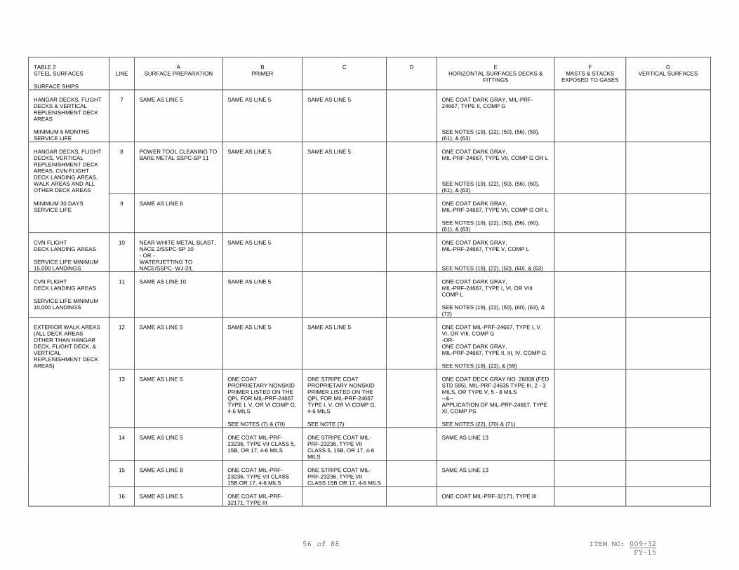
56 of 88 ITEM NO: 009-32 FY-15
TABLE 2 STEEL SURFACES SURFACE SHIPS
LINE
A
SURFACE PREPARATION
B
PRIMER
C
D
E
HORIZONTAL SURFACES DECKS & FITTINGS
F
MASTS & STACKS EXPOSED TO GASES
G
VERTICAL SURFACES
HANGAR DECKS, FLIGHT DECKS & VERTICAL REPLENISHMENT DECK AREAS MINIMUM 6 MONTHS SERVICE LIFE
7
SAME AS LINE 5
SAME AS LINE 5
SAME AS LINE 5
ONE COAT DARK GRAY, MIL-PRF-24667, TYPE II, COMP G SEE NOTES (19), (22), (50), (56), (59), (61), & (63)
HANGAR DECKS, FLIGHT DECKS, VERTICAL REPLENISHMENT DECK AREAS, CVN FLIGHT DECK LANDING AREAS, WALK AREAS AND ALL OTHER DECK AREAS
8
POWER TOOL CLEANING TO BARE METAL SSPC-SP 11
SAME AS LINE 5
SAME AS LINE 5
ONE COAT DARK GRAY, MIL-PRF-24667, TYPE VII, COMP G OR L SEE NOTES (19), (22), (50), (56), (60), (61), & (63)
MINIMUM 30 DAYS SERVICE LIFE
9
SAME AS LINE 8
ONE COAT DARK GRAY, MIL-PRF-24667, TYPE VII, COMP G OR L SEE NOTES (19), (22), (50), (56), (60), (61), & (63)
CVN FLIGHT DECK LANDING AREAS SERVICE LIFE MINIMUM 15,000 LANDINGS
10
NEAR WHITE METAL BLAST, NACE 2/SSPC-SP 10 - OR - WATERJETTING TO NACE/SSPC- WJ-2/L
SAME AS LINE 5
ONE COAT DARK GRAY, MIL-PRF-24667, TYPE V, COMP L SEE NOTES (19), (22), (50), (60), & (63)
CVN FLIGHT DECK LANDING AREAS SERVICE LIFE MINIMUM 10,000 LANDINGS
11
SAME AS LINE 10
SAME AS LINE 5
ONE COAT DARK GRAY, MIL-PRF-24667, TYPE I, VI, OR VIII COMP L SEE NOTES (19), (22), (50), (60), (63), & (72)
EXTERIOR WALK AREAS (ALL DECK AREAS OTHER THAN HANGAR DECK, FLIGHT DECK, & VERTICAL REPLENISHMENT DECK AREAS)
12
SAME AS LINE 5
SAME AS LINE 5
SAME AS LINE 5
ONE COAT MIL-PRF-24667, TYPE I, V, VI, OR VIII, COMP G -OR- ONE COAT DARK GRAY, MIL-PRF-24667, TYPE II, III, IV, COMP G SEE NOTES (19), (22), & (59)
13
SAME AS LINE 5
ONE COAT PROPRIETARY NONSKID PRIMER LISTED ON THE QPL FOR MIL-PRF-24667 TYPE I, V, OR VI COMP G, 4-6 MILS SEE NOTES (7) & (70)
ONE STRIPE COAT PROPRIETARY NONSKID PRIMER LISTED ON THE QPL FOR MIL-PRF-24667 TYPE I, V, OR VI COMP G, 4-6 MILS SEE NOTE (7)
ONE COAT DECK GRAY NO. 26008 (FED STD 595), MIL-PRF-24635 TYPE III, 2 - 3 MILS, OR TYPE V, 5 - 8 MILS --&-- APPLICATION OF MIL-PRF-24667, TYPE XI, COMP PS SEE NOTES (22), (70) & (71)
14
SAME AS LINE 5
ONE COAT MIL-PRF-23236, TYPE VII CLASS 5, 15B, OR 17, 4-6 MILS
ONE STRIPE COAT MIL-PRF-23236, TYPE VII CLASS 5, 15B, OR 17, 4-6 MILS
SAME AS LINE 13
15
SAME AS LINE 8
ONE COAT MIL-PRF-23236, TYPE VII CLASS 15B OR 17, 4-6 MILS
ONE STRIPE COAT MIL-PRF-23236, TYPE VII CLASS 15B OR 17, 4-6 MILS
SAME AS LINE 13
16
SAME AS LINE 5
ONE COAT MIL-PRF-32171, TYPE III
ONE COAT MIL-PRF-32171, TYPE III

57 of 88 ITEM NO: 009-32 FY-15
TABLE 2 STEEL SURFACES SURFACE SHIPS
LINE
A
SURFACE PREPARATION
B
PRIMER
C
D
E
HORIZONTAL SURFACES DECKS & FITTINGS
F
MASTS & STACKS EXPOSED TO GASES
G
VERTICAL SURFACES
RAST TRACK TROUGHS WHERE PAINTED (WHERE NONSKID NOT APPLIED)
17
SAME AS LINE ONE
ONE COAT MIL-PRF-23236, TYPE VII, CLASS 17, 6 - 8 MILS
ONE STRIPE COAT MIL-PRF-23236, TYPE VII, CLASS 17, 6 - 8 MILS SEE NOTE (23)
ONE COAT MIL-PRF-23236, TYPE VII, CLASS 17, 6 - 8 MILS
WELL DECK OVERHEADS, BOTH EXPOSED & NON-EXPOSED TO LCAC EXHAUST, AND ENCLOSED BOAT HANDLING AREA OVERHEADS SEE NOTE (34)
18
NEAR WHITE METAL BLAST, NACE 2/SSPC-SP 10 SEE NOTES (30) & (31)
ONE COAT MIL-PRF-23236, TYPE VII, CLASS 19, 4 - 8 MILS SEE NOTES (33) & (49)
ONE STRIPE COAT MIL-PRF-23236, TYPE VII, CLASS 19, 6 - 10 MILS SEE NOTES (23), (33) & (49)
ONE COAT MIL-PRF-23236, TYPE VII, CLASS 19, 10 - 12 MILS SEE NOTES (33) & (49)
19
SAME AS LINE 18
"SINGLE COAT" ONE COAT MIL-PRF- 23236 TYPE VII CLASS 19/18, 20-30 MILS SEE NOTES (24) & (33)
"SINGLE COAT" ONE STRIPE COAT MIL-PRF-23236 TYPE VII CLASS 19/18, 10-15 MILS SEE NOTES (23) & (33)
WELL DECK AND ENCLOSED BOAT HANDLING AREA BULKHEADS AND DECKS
20
SAME AS LINE 18
"SINGLE COAT" ONE COAT MIL-PRF-23236 TYPE VII CLASS 7/18, 20-30 MILS SEE NOTES (24) & (33)
"SINGLE COAT" ONE STRIPE COAT MIL-PRF-23236 TYPE VII CLASS 7/18, 10-15 MILS SEE NOTES (23) & (33)
EXTERIOR PORTABLE/BOLTED LOUVERS FOR INTAKES AND UPTAKES
21
SAME AS LINE ONE
ONE COAT MIL-PRF-23236, TYPE VII, CLASS 5 OR 7, 4 - 8 MILS SEE NOTES (33) & (49)
ONE STRIPE COAT MIL-PRF-23236, TYPE VII, CLASS 5 OR 7, 6 - 10 MILS SEE NOTES (23), (33) & (49)
ONE COAT MIL-PRF-23236, TYPE VII, CLASS 5 OR 7, 10 - 12 MILS SEE NOTES (33) & (49)
SAME AS LINE ONE
SAME AS LINE ONE
22
NEAR WHITE METAL BLAST, NACE 2/SSPC-SP 10
ONE COAT MIL-PRF-23236, TYPE VIIIA APPLIED BY FLUIDIZED BED METHOD ONLY
ONE COAT MIL-PRF-24712, TGIC POLYESTER, TOTAL SYSTEM 10 MILS MINIMUM SEE NOTE (67)
ONE COAT MIL-PRF-24712, TGIC POLYESTER, TOTAL SYSTEM 10 MILS MINIMUM SEE NOTE (67)
23
SAME AS LINE ONE
"SINGLE COAT" ONE COAT MIL-PRF-23236, TYPE VII, CLASS 7/18, 20-30 MILS SEE NOTES (24) & (33)
"SINGLE COAT" ONE STRIPE COAT MIL-PRF-23236, TYPE VII, CLASS 7/18, 10-15 MILS SEE NOTES (23) & (33)
SAME AS LINE ONE
SAME AS LINE ONE
DDG GAS TURBINE BOLTED AIR INTAKE AND EXHAUST LOUVERS
24
SAME AS LINE 22
SAME AS LINE 22
SAME AS LINE 22
SAME AS LINE 22
POWDER COATED WATERTIGHT DOORS: INTERIOR AND EXTERIOR
25
SAME AS LINE 22
ONE COAT MIL-PRF-23236, TYPE VIII APPLIED BY FLUIDIZED BED METHOD ONLY, 10 MILS MINIMUM
SAME AS LINE 22
SAME AS LINE 22

58 of 88 ITEM NO: 009-32 FY-15
TABLE 2 ALUMINUM SURFACES SURFACE SHIPS
LINE
A
SURFACE PREPARATION
B
PRIMER
C
D
E
HORIZONTAL SURFACES DECKS & FITTINGS
F
MASTS & STACKS EXPOSED TO
GASES
G
VERTICAL SURFACES
EXTERIOR SURFACES ABOVE BOOTTOP, WITH EXCEPTION OF AREAS RECEIVING NONSKID SEE NOTE (2)
26
NEAR WHITE METAL BLAST USING GARNET, ALUMINUM OXIDE, CRUSHED GLASS, BLACK WALNUT SHELLS, OR STAINLESS STEEL SHOT - OR - WATERJETTING TO NACE/SSPC WJ-2 SEE NOTE (21)
ONE COAT MIL-PRF-23236, TYPE V OR VI, CLASS 5 OR 7, 4 - 8 MILS -- OR -- ONE COAT MIL-PRF-23236, TYPE VII, CLASS 5 OR 7, 4 - 8 MILS
ONE STRIPE COAT MIL-PRF-23236, TYPE V OR VI, CLASS 5 OR 7, 4 - 8 MILS -- OR -- ONE STRIPE COAT MIL-PRF-23236, TYPE VII, CLASS 5 OR 7, 6 - 10 MILS SEE NOTE (23)
ONE FULL COAT MIL-PRF-23236, TYPE V OR VI, CLASS 5 OR 7, 4 - 8 MILS -- OR -- ONE FULL COAT MIL-PRF-23236, TYPE VII, CLASS 5 OR 7,10 - 12 MILS
ONE COAT DECK GRAY NO. 26008 (FED STD 595), MIL-PRF-24635 TYPE III GRADE B, 2 - 3 MILS SEE NOTE (47)
ONE COAT HAZE GRAY NO. 26270 (FED STD 595), MIL-PRF-24635 TYPE III GRADE B, 2 - 3 MILS - OR - MIL-PRF-24763 TYPE II OR III, CLASS 2, GRADE B, 2 - 4 MILS SEE NOTE (42)
ONE COAT HAZE GRAY NO. 26270 (FED STD 595), MIL-PRF-24635 TYPE III GRADE B, 2 - 3 MILS - OR - MIL-PRF-24763 TYPE II OR III, CLASS 2, GRADE B, 2 - 4 MILS PAINT DESIGNATIONS & MARKINGS MIL-PRF-24635 , 2 - 3 MILS SEE NOTES (43) & (47)
27
SAME AS LINE 26
2 COATS F-84, TT-P-645, ALKYD ZINC MOLYBDATE, 1.5 - 3 MILS/COAT
SAME AS LINE 26
SAME AS LINE 26
SAME AS LINE 26
28
SAME AS LINE 26
ONE STRIPE COAT MIL-PRF-23236, TYPE V OR VI, CLASS 5 OR 7, 4 - 8 MILS -- OR -- ONE STRIPE COAT MIL-PRF-23236, TYPE VII, CLASS 5 OR 7, 6 - 10 MILS --OR— ONE STRIPE COAT MIL-PRF-24635, TYPE V OR VI, CLASS 2, 5-8 MILS DECK GRAY SEE NOTE (23)
ONE COAT MIL-PRF-24635, TYPE V OR VI, CLASS 2, 5 - 8 MILS DECK GRAY
ONE COAT MIL-PRF-24635, TYPE V OR VI, CLASS 2, 5 - 8 MILS, HAZE GRAY
ONE COAT MIL-PRF-24635, TYPE V OR VI, CLASS 2, 5 - 8 MILS, HAZE GRAY
HANGAR DECKS, FLIGHT DECKS & VERTICAL REPLENISHMENT DECK AREAS MINIMUM 3 YEARS SERVICE LIFE
29
NEAR WHITE METAL BLAST USING GARNET, ALUMINUM OXIDE, CRUSHED GLASS, BLACK WALNUT SHELLS, OR STAINLESS STEEL SHOT - OR - WATERJETTING TO NACE/SSPC WJ-2 SEE NOTES (16) & (21)
ONE COAT PROPRIETARY NONSKID PRIMER LISTED ON THE QPL FOR MIL-PRF-24667 (OF TYPE TO MATCH COLUMN E) SEE NOTE (7)
ONE COAT DARK GRAY, MIL-PRF-24667, TYPE V, COMP G SEE NOTES (19), (22), (50), (56), (59), (61), & (63)
HANGAR DECKS, FLIGHT DECKS & VERTICAL REPLENISHMENT DECK AREAS MINIMUM 12 MONTHS SERVICE LIFE
30
SAME AS LINE 29
SAME AS LINE 29
ONE COAT DARK GRAY MIL-PRF-24667, TYPE I, VI, OR VIII, COMP G SEE NOTES (19), (22), (50), (56), (59), (61), (63), & (72)
HANGAR DECKS, FLIGHT DECKS & VERTICAL REPLENISHMENT DECK AREAS MINIMUM 6 MONTHS SERVICE LIFE
31
SAME AS LINE 29
SAME AS LINE 29
ONE COAT DARK GRAY MIL-PRF-24667 TYPE II, COMP G SEE NOTES (19), (22), (50), (56), (59), (61), & (63)

59 of 88 ITEM NO: 009-32 FY-15
TABLE 2 ALUMINUM SURFACES SURFACE SHIPS
LINE
A
SURFACE PREPARATION
B
PRIMER
C
D
E
HORIZONTAL SURFACES DECKS & FITTINGS
F
MASTS & STACKS EXPOSED TO
GASES
G
VERTICAL SURFACES
HANGAR DECKS, FLIGHT DECKS, VERTICAL REPLENISHMENT DECK AREAS, CVN FLIGHT DECK LANDING AREAS, WALK AREAS AND ALL OTHER DECK AREAS MINIMUM 30 DAYS SERVICE LIFE
32
POWER TOOL CLEAN TO BARE METAL, SSPC-SP 11
SAME AS LINE 29
ONE COAT DARK GRAY, MIL-PRF-24667, TYPE VII, COMP G OR L SEE NOTES (19), (22), (50), (56), (60), (61), & (63)
33
SAME AS LINE 32
ONE COAT DARK GRAY, MIL-PRF-24667, TYPE VII, COMP G OR L SEE NOTES (19), (22), (50), (56), (60), (61), & (63)
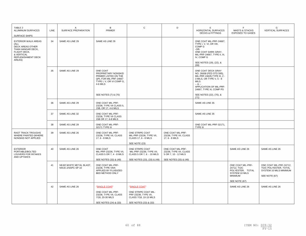
60 of 88 ITEM NO: 009-32 FY-15
TABLE 2 ALUMINUM SURFACES SURFACE SHIPS
LINE
A
SURFACE PREPARATION
B
PRIMER
C
D
E
HORIZONTAL SURFACES DECKS & FITTINGS
F
MASTS & STACKS EXPOSED TO GASES
G
VERTICAL SURFACES
EXTERIOR WALK AREAS (ALL DECK AREAS OTHER THAN HANGAR DECK, FLIGHT DECK, & VERTICAL REPLENISHMENT DECK AREAS)
34
SAME AS LINE 29
SAME AS LINE 29
ONE COAT MIL-PRF-24667, TYPE I, V, VI, OR VIII, COMP G -OR- ONE COAT DARK GRAY, MIL-PRF-24667, TYPE II, III, IV, COMP G SEE NOTES (19), (22), & (59)
35
SAME AS LINE 29
ONE COAT PROPRIETARY NONSKID PRIMER LISTED ON THE QPL FOR MIL-PRF-24667 TYPE I, V, OR VI COMP G, 4-6 MILS SEE NOTES (7) & (70)
ONE COAT DECK GRAY NO. 26008 (FED STD 595), MIL-PRF-24635,TYPE III, 2 - 3 MILS, OR TYPE V, 5 - 8 MILS -- & -- APPLICATION OF MIL-PRF-24667, TYPE XI, COMP PS SEE NOTES (22), (70), & (71)
36
SAME AS LINE 29
ONE COAT MIL-PRF-23236, TYPE VII CLASS 5, 15B, OR 17, 4-6 MILS
SAME AS LINE 35
37
SAME AS LINE 32
ONE COAT MIL-PRF-23236, TYPE VII CLASS 15B OR 17, 6-8 MILS
SAME AS LINE 35
38
SAME AS LINE 29
ONE COAT MIL-PRF-32171 TYPE III
ONE COAT MIL-PRF-32171, TYPE III
RAST TRACK TROUGHS WHERE PAINTED (WHERE NONSKID NOT APPLIED
39
SAME AS LINE 26
ONE COAT MIL-PRF-23236, TYPE VII, CLASS 17, 6 - 8 MILS
ONE STRIPE COAT MIL-PRF-23236, TYPE VII, CLASS 17, 6 - 8 MILS SEE NOTE (23)
ONE COAT MIL-PRF-23236, TYPE VII, CLASS 17, 6 - 8 MILS
EXTERIOR PORTABLE/BOLTED LOUVERS FOR INTAKES AND UPTAKES
40
SAME AS LINE 26
ONE COAT MIL-PRF-23236, TYPE VII, CLASS 5 OR 7, 4 - 8 MILS SEE NOTES (33) & (49)
ONE STRIPE COAT MIL-PRF-23236, TYPE VII, CLASS 5 OR 7, 6 - 10 MILS SEE NOTES (23), (33) & (49)
ONE COAT MIL-PRF-23236, TYPE VII, CLASS 5 OR 7, 10 - 12 MILS SEE NOTES (33) & (49)
SAME AS LINE 26
SAME AS LINE 26
41
NEAR WHITE METAL BLAST, NACE 2/SSPC-SP 10
ONE COAT MIL-PRF-23236, TYPE VIIIA APPLIED BY FLUIDIZED BED METHOD ONLY
ONE COAT MIL-PRF-24712, TGIC POLYESTER, TOTAL SYSTEM 10 MILS MINIMUM SEE NOTE (67)
ONE COAT MIL-PRF-24712, TGIC POLYESTER, TOTAL SYSTEM 10 MILS MINIMUM SEE NOTE (67)
42
SAME AS LINE 26
"SINGLE COAT" ONE COAT MIL-PRF-23236, TYPE VII, CLASS 7/18, 20-30 MILS SEE NOTES (24) & (33)
"SINGLE COAT" ONE STRIPE COAT MIL-PRF-23236, TYPE VII, CLASS 7/18, 10-15 MILS SEE NOTES (23) & (33)
SAME AS LINE 26
SAME AS LINE 26

61 of 88 ITEM NO: 009-32 FY-15
TABLE 2 GRP FIBERGLASS SURFACES SURFACE SHIPS
LINE
A
SURFACE PREPARATION
B
PRIMER
C
D
E
HORIZONTAL SURFACES DECKS & FITTINGS
F
MASTS & STACKS EXPOSED TO GASES
G
VERTICAL SURFACES
EXTERIOR SURFACES ABOVE BOOTTOP SEE NOTE (2)
43
HIGH PRESSURE WASH TO REMOVE MARINE GROWTH & LOOSE PAINT - OR - TOUCH-UP OR REMOVAL OF PAINT SYSTEM TO SOUND PRIMER BY LIGHT ABRASIVE BLASTING WITH BLACK WALNUT SHELLS -- & -- SPOT CLEAN, CHAP 631, PARA 631-5.2.6 SEE NOTE (21)
ONE COAT F-150, MIL-DTL-24441, TYPE IV, 4 - 6 MILS SEE NOTE (29)
ONE STRIPE COAT MIL-DTL-24441, TYPE IV, 4 - 6 MILS -- & -- ONE COAT MIL-DTL-24441, TYPE IV, 4 - 6 MILS SEE NOTE (29)
ONE COAT DECK GRAY NO. 26008 (FED STD 595), MIL-PRF-24635 TYPE III, GRADE B, 2 - 3 MILS
ONE COAT HAZE GRAY NO. 26270 (FED STD 595), MIL-PRF-24635 TYPE III, GRADE B, 2 - 3 MILS - OR - MIL-PRF-24763, TYPE II OR III, CLASS 2, GRADE B, 2 - 4 MILS SEE NOTE (42)
ONE COAT HAZE GRAY NO. 26270 (FED STD 595), MIL-PRF-24635 TYPE III, GRADE B, 2 - 3 MILS - OR - MIL-PRF-24763, TYPE II OR III, CLASS 2, GRADE B, 2 - 4 MILS IDENTIFICATION MARKINGS: PAINT DESIGNATIONS & MARKINGS MIL-PRF-24635 TYPE III, 2 - 3 MILS SEE NOTE (43)
EXTERIOR WALK AREAS ALL EXTERIOR DECK AREAS
44
POWER TOOL CLEAN TO CLEAN FIBERGLASS (DISC SANDER, ETC.) - OR - POWER TOOL CLEAN TO POLYURETHANE OVERLAY SUBSTRATE (DISC SANDER, ETC.) - OR - HYDROBLAST TO CLEAN FIBERGLASS SEE NOTES (25) & (62)
PROPRIETARY NONSKID PRIMER LISTED ON THE QPL FOR MIL-PRF-24667 SEE NOTE (7)
ONE COAT MIL-PRF-24667, TYPE I, II, OR III, COMP G - OR - MIL-PRF-24667 TYPE IV SEE NOTES (19) & (22)
45
SAME AS LINE 44
ONE COAT F-150, MIL-DTL-24441, TYPE IV, 4 - 6 MILS
ONE COAT DECK GRAY NO. 26008 (FED STD 595), MIL-PRF-24635 TYPE III, GRADE B, 2 - 3 MILS --&-- APPLICATION OF MIL-PRF-24667, TYPE XI, COMPOSITION PS SEE NOTE (71)

62 of 88 ITEM NO: 009-32 FY-15
TABLE 2 WOOD SURFACES SURFACE SHIPS
LINE
A
SURFACE PREPARATION
B
PRIMER
C
D
E
HORIZONTAL SURFACES DECKS & FITTINGS
F
MASTS & STACKS EXPOSED TO GASES
G
VERTICAL SURFACES
EXTERIOR ABOVE BOOTTOPPING
46
HAND TOOL CLEAN - OR - POWER TOOL CLEAN TO REMOVE DETERIORATED COATINGS
ONE COAT F-150, MIL-DTL-24441, TYPE IV, 4 - 6 MILS
DECKS, MASTS & SPARS: ONE COAT NO. 26008 (FED STD 595), MIL-PRF-24635 TYPE III, GRADE B, 2 - 3 MILS - OR - ONE COAT NO. 37038 (FED STD 595), MIL-PRF-24635, 2 - 3 MILS
ALL OTHER SURFACES: ONE COAT HAZE GRAY NO. 26270 (FED STD 595), MIL-PRF-24635 TYPE III, GRADE B, 2 - 3 MILS
IDENTIFICATION MARKINGS: PAINT DESIGNATIONS & MARKINGS MIL-PRF-24635 TYPE III,, 2 - 3 MILS SEE NOTE (43)

63 of 88 ITEM NO: 009-32 FY-15
TABLE 3 STEEL SURFACES SURFACE SHIPS
LINE
A
SURFACE PREPARATION
B
PRIMER
C
D
BULKHEADS & OVERHEADS
E
DECKS
F
INSULATION
G
MARKINGS
INTERIOR COMPARTMENTS COLORS TO BE SPECIFIED BY TYCOM OR SHIP'S COMMANDING OFFICER PER CHAP 631, PARA 631-8.18.3.2
1
HAND TOOL CLEANING, SSPC-SP 2 SEE NOTES (17) & (28)
2 COATS FORMULA 84, TT-P-645, ALKYD ZINC MOLYBDATE, 1.5 - 3 MILS/COAT - OR - ONE COAT MIL-PRF-23236, TYPE V, VI, OR VII, CLASS 5 OR 7, 4 - 8 MILS --OR-- ONE COAT MIL-PRF-32171, TYPE I, CLASS 1 OR 2, 10 – 12 MILS
2 COATS MIL-PRF-24596, WATER-BASED INTERIOR LATEX, 2 - 4 MILS/COAT - OR - 2 COATS MIL-DTL-24607, 1.5 - 3 MILS/COAT SEE NOTE (9)
TO DECKS NOT RECEIVING COVERING: ONE COAT DECK GRAY (OR TERRACOTTA RED) (FED STD 595) MIL-PRF-23236, TYPE V VI, OR VII, CLASS 5 OR 7, 4 - 8 MILS - OR - MIL-PRF-32171, TYPE I, CLASS 1 OR 2, 10 - 12 MILS
HULL, VENTILATION & PIPING INSULATION 2 COATS MIL-PRF-24596, WATER-BASED INTERIOR LATEX, 2 - 4 MILS/COAT SEE NOTES (9), (28) & (41)
FOR COMPARTMENT PIPING & VENTILATION SEE NOTE (18)
INTERIOR COMPARTMENTS (OVERCOAT)
2
HAND TOOL CLEANING, SSPC-SP 2 SEE NOTE (28)
SAME AS LINE ONE FOR BARE METAL AREAS
SAME AS LINE ONE EXCEPT ONE COAT
SAME AS LINE ONE
SAME AS LINE ONE EXCEPT ONE COAT
SAME AS LINE ONE EXCEPT ONE COAT
WELDING BAYS AND LIGHT TRAPS
3
SAME AS LINE ONE
SAME AS LINE ONE
ONE COAT BLACK, LOW GLOSS (FED STD 595), MIL-PRF-23236, TYPE V VI, OR VII, 4 - 8 MILS
ONE COAT BLACK, SEMI-GLOSS (FED STD 595): MIL-PRF-23236, TYPE V VI, OR VII, 4 - 8 MILS - OR - MIL-PRF-32171, TYPE I, CLASS 1 OR 2, 10 - 12 MILS
WET SPACES (WASH ROOMS, WATER CLOSETS, SHOWER STALLS, GALLEYS, SCULLERIES, & STOREROOMS WHERE HEAVY CONDENSATION IS COMMON)
4
POWER TOOL CLEAN TO BARE METAL, SSPC-SP 11 SEE NOTE (28)
ONE COAT SIGMAGLAZE 5492, WHITE ONLY, 8-10 MILS
ONE STRIPE COAT SIGMAGLAZE 5492, 8-10 MILS, -- & -- ONE FULL COAT, SIGMAGLAZE 5492, 8-10 MILS, WHITE ONLY SEE NOTE (23)
SAME AS LINE ONE
SAME AS LINE ONE
5
SAME AS LINE 4
ONE COAT MIL-PRF-23236, TYPE VII, CLASS 17, 6 - 8 MILS
ONE STRIPE COAT SHERWIN WILLIAMS DURAPLATE UHS, 6 - 10 MILS -- & -- ONE FULL COAT, 10 - 12 MILS SEE NOTE (23)
SAME AS LINE ONE
SAME AS LINE ONE
6
SAME AS LINE 4
SAME AS LINE 5
ONE STRIPE COAT MIL-PRF-23236, TYPE VII, CLASS 17, 6 - 8 MILS -- & -- ONE FULL COAT MIL-PRF-24635, TYPE V OR VI, 5 - 8 MILS SEE NOTE (23)
SAME AS LINE ONE
SAME AS LINE ONE
7
SAME AS LINE 4
ONE COAT MIL-PRF-23236, TYPE VII, CLASS 17, 6 - 8 MILS --OR-- ONE COAT MIL-PRF-32171, TYPE I, CLASS 1 OR 2, 10 – 12 MILS
ONE STRIPE COAT MIL-PRF-23236, TYPE VII, CLASS 17, 6 - 8 MILS -- & -- ONE FULL COAT 6 - 8 MILS SEE NOTE (23)
SAME AS LINE ONE
SAME AS LINE ONE
INTERIOR COMPARTMENTS COLORS TO BE SPECIFIED BY TYCOM OR SHIP'S COMMANDING OFFICER PER CHAP 631, PARA 631-8.18.3.2
8
POWER TOOL CLEAN TO BARE METAL, SSPC-SP 11 SEE NOTES (17) & (28)
2 COATS FORMULA 84, TT-P-645, 1.5 - 3 MILS/COAT - OR - ONE COAT MIL-PRF-23236, TYPE V, VI, OR VII, CLASS 5 OR 7, 4 - 8 MILS --OR-- ONE COAT MIL-PRF-32171, TYPE I, CLASS 1 OR 2, 10 – 12 MILS
2 COATS MIL-PRF-24596, WATER-BASED INTERIOR LATEX, 2 - 4 MILS/COAT - OR - 2 COATS MIL-DTL-24607, 1.5 - 3 MILS/COAT SEE NOTE (9)
TO DECKS NOT RECEIVING COVERING: ONE COAT DECK GRAY (OR TERRACOTTA RED) (FED STD 595) MIL-PRF-23236, TYPE V, VI, OR VII, CLASS 5 OR 7, 4 - 8 MILS - OR - MIL-PRF-32171, TYPE I, CLASS 1 OR 2, 10 - 12 MILS
SAME AS LINE ONE
SAME AS LINE ONE

64 of 88 ITEM NO: 009-32 FY-15
TABLE 3 STEEL SURFACES SURFACE SHIPS
LINE
A
SURFACE PREPARATION
B
PRIMER
C
D
BULKHEADS & OVERHEADS
E
DECKS
F
INSULATION
G
MARKINGS
INTERIOR COMPARTMENTS (OVERCOAT)
9
POWER TOOL CLEANING, SSPC-SP 3 SEE NOTE (28)
SAME AS LINE ONE FOR BARE METAL AREAS
SAME AS LINE ONE EXCEPT ONE COAT
SAME AS LINE ONE
SAME AS LINE ONE EXCEPT ONE COAT
SAME AS LINE ONE EXCEPT ONE COAT
WELDING BAYS AND LIGHT TRAPS
10
SAME AS LINE 8
SAME AS LINE 8
SAME AS LINE 3
SAME AS LINE 3
MACHINERY SPACES & BILGES SEE NOTE (44)
11
POWER TOOL CLEAN TO BARE METAL, SSPC-SP 11 - OR - WATERJETTING TO NACE/SSPC WJ-2/L - OR - NEAR WHITE METAL BLAST, NACE 2/SSPC-SP 10 SEE NOTE (28)
ONE COAT MIL-PRF-23236, TYPE VII, CLASS 17, 6 - 8 MILS
ABOVE BILGE AREA: 2 COATS F-124, MIL-DTL-24607, 1.5 - 3 MILS/COAT
BILGE AREA: ONE STRIPE COAT MIL-PRF-23236, TYPE VII, CLASS 17, 6 - 8 MILS -- & -- ONE COAT MIL-PRF-23236, TYPE VII, CLASS 17, 6 - 8 MILS SEE NOTE (23)
SAME AS LINE ONE
12
NEAR WHITE METAL BLAST, NACE 2/SSPC-SP 10 SEE NOTE (28)
ONE COAT MIL-PRF-23236, TYPE VII, CLASS 5, 4 - 8 MILS SEE NOTE (49)
SAME AS LINE 11
BILGE AREA: ONE STRIPE COAT MIL-PRF-23236, TYPE VII, CLASS 5, 6 - 10 MILS -- & -- ONE COAT MIL-PRF-23236, TYPE VII, CLASS 5, 10 - 12 MILS SEE NOTES (23) & (49)
SAME AS LINE ONE
13
SAME AS LINE 12
"SINGLE COAT" ONE COAT MIL-PRF-23236 TYPE VII CLASS 5/18 OR 17/18, 20-30 MILS SEE NOTES (24) & (33)
SAME AS LINIE 11
BILGE AREA: ONE STRIPE COAT MIL-PRF-23236 TYPE VII CLASS 5/18 OR 17/18, 10-15 MILS SEE NOTES (23), (24) & (33)
SAME AS LINE ONE
VENT PLENUMS
14
NEAR WHITE METAL BLAST, NACE 2/SSPC-SP 10
ONE COAT MIL-PRF-23236, TYPE VII, CLASS 5, 4 - 8 MILS SEE NOTES (33) & (49)
ONE STRIPE COAT MIL-PRF-23236, TYPE VII, CLASS 5, 6 - 10 MILS -- & -- ONE COAT MIL-PRF-23236, TYPE VII, CLASS 5, 10 - 12 MILS SEE NOTES (23), (33) & (49)
ONE STRIPE COAT MI-PRF-23236, TYPE VII, CLASS 5, 6 - 10 MILS -- & -- ONE COAT MIL-PRF-23236, TYPE VII, CLASS 5, 10 - 12 MILS SEE NOTES (23), (33) & (49)
15
SAME AS LINE 14
"SINGLE COAT" ONE COAT MIL-PRF-23236 TYPE VII CLASS 5/18, 20-30 MILS SEE NOTES (24) & (33)
"SINGLE COAT" ONE STRIPE COAT MIL-PRF-23236 TYPE VII CLASS 5/18, 10-15 MILS SEE NOTES (23) & (33)
"SINGLE COAT" ONE STRIPE COAT MIL-PRF-23236 TYPE VII CLASS 5/18, 10-15 MILS SEE NOTES (23) & (33)
16
WATERJETTING TO NACE/SSPC WJ-2/L -OR- NEAR WHITE METAL BLAST, NACE 2/SSPC-SP 10
ONE COAT MIL-PRF-23236, TYPE VII, CLASS 17, 6 - 8 MILS SEE NOTE (33)
ONE STRIPE COAT MIL-PRF-23236, TYPE VII, CLASS 17, 6 - 8 MILS -- & -- ONE COAT MIL-PRF-23236, TYPE VII, CLASS 17, 6 - 8 MILS SEE NOTES (23) & (33)
ONE STRIPE COAT MIL-PRF-23236, TYPE VII, CLASS 17, 6 - 8 MILS -- & -- ONE COAT MIL-PRF-23236, TYPE VII, CLASS 17, 6 - 8 MILS SEE NOTES (23) & (33)

65 of 88 ITEM NO: 009-32 FY-15
TABLE 3 STEEL SURFACES SURFACE SHIPS
LINE
A
SURFACE PREPARATION
B
PRIMER
C
D
BULKHEADS & OVERHEADS
E
DECKS
F
INSULATION
G
MARKINGS
CLEAN AND DIRTY SIDE OF COMBUSTION AIR INTAKES/ EXHAUST TRUNKS
17
NEAR WHITE METAL BLAST, NACE 2/SSPC-SP 10
ONE COAT MIL-PRF-23236, TYPE VII, CLASS 7, 4 - 8 MILS SEE NOTE (33)
ONE STRIPE COAT MIL-PRF-23236, TYPE VII, CLASS 7, 6 - 10 MILS -- & -- ONE FULL COAT MIL-PRF-23236, TYPE VII, CLASS 7, 10 - 12 MILS SEE NOTES (23) & (33)
ONE STRIPE COAT MIL-PRF-23236, TYPE VII, CLASS 7, 6 - 10 MILS -- & -- ONE FULL COAT MIL-PRF-23236, TYPE VII, CLASS 7,10 - 12 MILS SEE NOTES (23) & (33)
18
WATERJETTING TO NACE/SSPC WJ-2/L - OR - NEAR WHITE METAL BLAST, NACE 2/SSPC-SP 10 - OR - POWER TOOL CLEAN TO BARE METAL, SSPC-SP 11
ONE COAT MIL-PRF-23236, TYPE VII, CLASS 17, 6 - 8 MILS SEE NOTE (33)
ONE STRIPE COAT MIL-PRF-23236, TYPE VII, CLASS 17, 6 - 8 MILS -- & -- ONE COAT MIL-PRF-23236, TYPE VII, CLASS 17, 6 - 8 MILS SEE NOTES (23) & (33)
ONE STRIPE COAT MIL-PRF-23236, TYPE VII, CLASS 17, 6 - 8 MILS -- & -- ONE COAT MIL-PRF-23236, TYPE VII, CLASS 17, 6 - 8 MILS SEE NOTES (23) & (33)
FAN ROOMS
19
SAME AS LINE 11
SAME AS LINE 18
SAME AS LINE 18
SAME AS LINE 18
MIXING ROOM/GAS TURBINE EXHAUST UPTAKE SPACES AND TRUNKS WITH VENTS OR LOUVERS TO THE OUTSIDE ATMOSPHERE (BULKHEADS & DECKS)
20
NEAR WHITE METAL BLAST NACE 2/SSPC-SP 10
ONE COAT MIL-PRF-23236, TYPE VII, CLASS 5, 4 - 8 MILS SEE NOTES (33) & (49)
ONE STRIPE COAT MIL-PRF-23236, TYPE VII, CLASS 5, 6 - 10 MILS -- & -- ONE COAT MIL-PRF-23236, TYPE VII, CLASS 5, 10 - 12 MILS SEE NOTES (23), (33) & (49)
ONE STRIPE COAT MIL-PRF-23236, TYPE VII, CLASS 5, 6 - 10 MILS -- & -- ONE COAT MIL-PRF-23236, TYPE VII, CLASS 5, 10 - 12 MILS SEE NOTES (23), (33) & (49)
UNDER AFFF PROPORTIONING UNITS (INSIDE THE COAMING), OR BILGE DRAIN WELLS
21
POWER TOOL CLEAN TO BARE METAL, SSPC-SP 11 SEE NOTES (32) & (36)
ONE COAT MIL-PRF-32171, TYPE IV, CLASS 1 OR 2, 12 - 18 MILS
ONE COAT MIL-PRF-32171, TYPE IV, CLASS 1 OR 2, 12 - 18 MILS
INTERIOR DECK PASSAGEWAYS NOT RECEIVING DECK COVERINGS (HIGH DURABILITY DECK PAINT)
22
NEAR WHITE METAL BLAST, NACE 2/SSPC-SP 10 - OR - POWER TOOL CLEAN TO BARE METAL, SSPC-SP 11
ONE COAT MIL-PRF-32171, TYPE I, CLASS 1 OR 2, 10 - 12 MILS
ONE COAT MIL-PRF-32171, TYPE I, CLASS 1 OR 2, 10 - 12 MILS
SEE NOTE (12)
23
SAME AS LINE 22
SAME AS LINE 21
SAME AS LINE 21
INTERIOR STEEL SURFACES
24
SAME AS LINE 14
SAME AS LINE ONE
SAME AS LINE ONE
SAME AS LINE ONE
SAME AS LINE ONE
SAME AS LINE ONE
25
SAME AS LINE 16
SAME AS LINE ONE
SAME AS LINE ONE
SAME AS LINE ONE
SAME AS LINE ONE
SAME AS LINE ONE
26
SAME AS LINE 22
SAME AS LINE ONE
SAME AS LINE ONE
SAME AS LINE ONE
SAME AS LINE ONE
SAME AS LINE ONE

66 of 88 ITEM NO: 009-32 FY-15
TABLE 3 ALUMINUM SURFACES SURFACE SHIPS
LINE
A
SURFACE PREPARATION
B
PRIMER
C
D
BULKHEADS & OVERHEADS
E
DECKS
F
INSULATION
G
MARKINGS
INTERIOR COMPARTMENTS
27
POWER TOOL CLEAN TO BARE METAL, SSPC-SP 11, USING STAINLESS STEEL WIRE BRUSHES, STAINLESS STEEL PADS, OR ABRASIVE SANDING DISCS (ANSI/BHMA B74.18) SEE NOTES (17) & (28)
2 COATS FORMULA 84, TT-P-645, ALKYD ZINC MOLYBDATE, 1.5 - 3 MILS/COAT - OR - ONE COAT MIL-PRF-23236, TYPE V VI, OR VII, CLASS 5 OR 7, 4 - 8 MILS --OR-- ONE COAT MIL-PRF-32171, TYPE I, CLASS 1 OR 2, 10 – 12 MILS
2 COATS MIL-DTL-24607, 1.5 - 3 MILS/COAT - OR - 2 COATS MIL-PRF-24596, WATER-BASED INTERIOR LATEX, 2 - 4 MILS/COAT SEE NOTE (9)
TO DECKS NOT RECEIVING COVERING: ONE COAT DECK GRAY (OR TERRACOTTA RED) (FED STD 595), MIL-PRF-23236, TYPE V, VI, OR VII, CLASS 5 OR 7, 4 - 8 MILS - OR - MIL-PRF-32171, TYPE I, CLASS 1 OR 2, 10 - 12 MILS
HULL, VENTILATION & PIPING INSULATION 2 COATS MIL-DTL-24607, 1.5 - 3 MILS/COAT - OR - 2 COATS MIL-PRF-24596, WATER-BASED INTERIOR LATEX, 2 - 4 MILS/COAT SEE NOTES (9), (28) & (41)
FOR COMPARTMENT PIPING & VENTILATION SEE NOTE (18)
28
HAND TOOL CLEANING, SSPC-SP 2 SEE NOTES (17) & (28)
SAME AS LINE 27
SAME AS LINE 27
SAME AS LINE 27
SAME AS LINE 27
SAME AS LINE 27
INTERIOR COMPARTMENTS (OVERCOAT)
29
HAND TOOL CLEANING, SSPC-SP 2 SEE NOTE (28)
SAME AS LINE 27 FOR BARE METAL AREAS
SAME AS LINE 27 EXCEPT ONE COAT
SAME AS LINE 27
SAME AS LINE 27 EXCEPT ONE COAT
SAME AS LINE 27
30
POWER TOOL CLEANING, SSPC-SP 3 SEE NOTE (28)
SAME AS LINE 27 FOR BARE METAL AREAS
SAME AS LINE 27 EXCEPT ONE COAT
SAME AS LINE 27
SAME AS LINE 27 EXCEPT ONE COAT
SAME AS LINE 27
WELDING BAYS AND LIGHT TRAPS
31
SAME AS LINE 27
SAME AS LINE 27
ONE COAT BLACK, LOW GLOSS (FED STD 595), MIL-PRF-23236, TYPE V, VI, OR VII, 4 - 8 MILS
ONE COAT BLACK, SEMI-GLOSS (FED STD 595): MIL-PRF-23236, TYPE V, VI, OR VII, 4 - 8 MILS - OR - MIL-PRF-32171, TYPE I, CLASS 1 OR 2, 10 - 12 MILS
32
SAME AS LINE 28
SAME AS LINE 27
SAME AS LINE 31
SAME AS LINE 31
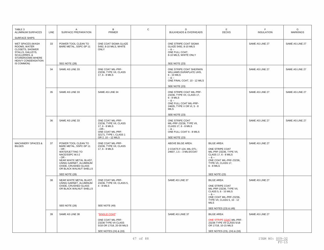
67 of 88 ITEM NO: 009-32 FY-15
TABLE 3 ALUMINUM SURFACES SURFACE SHIPS
LINE
A
SURFACE PREPARATION
B
PRIMER
C
D
BULKHEADS & OVERHEADS
E
DECKS
F
INSULATION
G
MARKINGS
WET SPACES (WASH ROOMS, WATER CLOSETS, SHOWER STALLS, GALLEYS, SCULLERIES, & STOREROOMS WHERE HEAVY CONDENSATION IS COMMON)
33
POWER TOOL CLEAN TO BARE METAL, SSPC-SP 11 SEE NOTE (28)
ONE COAT SIGMA GLAZE 5492, 8-10 MILS, WHITE ONLY
ONE STRIPE COAT SIGMA GLAZE 5492, 8-10 MILS -- & -- ONE FULL COAT, 8-10 MILS, WHITE ONLY SEE NOTE (23)
SAME AS LINE 27
SAME AS LINE 27
34
SAME AS LINE 33
ONE COAT MIL-PRF-23236, TYPE VII, CLASS 17, 6 - 8 MILS
ONE STRIPE COAT SHERWIN WILLIAMS DURAPLATE UHS, 6 - 10 MILS -- & -- ONE FINAL COAT, 10 - 12 MILS SEE NOTE (23)
SAME AS LINE 27
SAME AS LINE 27
35
SAME AS LINE 33
SAME AS LINE 34
ONE STRIPE COAT MIL-PRF-23236, TYPE VII, CLASS 17, 6 - 8 MILS -- & -- ONE FULL COAT MIL-PRF-24635, TYPE V OR VI, 5 - 8 MILS SEE NOTE (23)
SAME AS LINE 27
SAME AS LINE 27
36
SAME AS LINE 33
ONE COAT MIL-PRF-23236, TYPE VII, CLASS 17, 6 - 8 MILS --OR-- ONE COAT MIL-PRF-32171, TYPE I, CLASS 1 OR 2, 10 – 12 MILS
ONE STRIPE COAT MIL-PRF-23236, TYPE VII, CLASS 17, 6 - 8 MILS -- & -- ONE FULL COAT 6 - 8 MILS SEE NOTE (23)
SAME AS LINE 27
SAME AS LINE 27
MACHINERY SPACES & BILGES
37
POWER TOOL CLEAN TO BARE METAL, SSPC-SP 11 - OR - WATERJETTING TO NACE/SSPC WJ-2 - OR - NEAR WHITE METAL BLAST, USING GARNET, ALUMINUM OXIDE, CRUSHED GLASS OR BLACK WALNUT SHELLS SEE NOTE (28)
ONE COAT MIL-PRF-23236, TYPE VII, CLASS 17, 6 - 8 MILS
ABOVE BILGE AREA: 2 COATS F-124, MIL-DTL-24607, 1.5 – 3 MILS/COAT
BILGE AREA: ONE STRIPE COAT MIL-PRF-23236, TYPE VII, CLASS 17, 6 - 8 MILS -- & -- ONE COAT MIL-PRF-23236, TYPE VII, CLASS 17, 6 - 8 MILS SEE NOTE (23)
SAME AS LINE 27
38
NEAR WHITE METAL BLAST, USING GARNET, ALUMINUM OXIDE, CRUSHED GLASS OR BLACK WALNUT SHELLS SEE NOTE (28)
ONE COAT MIL-PRF-23236, TYPE VII, CLASS 5, 4 - 8 MILS SEE NOTE (49)
SAME AS LINE 37
BILGE AREA: ONE STRIPE COAT MIL-PRF-23236, TYPE VII, CLASS 5, 6 - 10 MILS -- & -- ONE COAT MIL-PRF-23236, TYPE VII, CLASS 5, 10 - 12 MILS SEE NOTES (23) & (49)
SAME AS LINE 27
39
SAME AS LINE 38
"SINGLE COAT" ONE COAT MIL-PRF-23236 TYPE VII CLASS 5/18 OR 17/18, 20-30 MILS SEE NOTES (24) & (33)
SAME AS LINIE 37
BILGE AREA: ONE STRIPE COAT MIL-PRF-23236 TYPE VII CLASS 5/18 OR 17/18, 10-15 MILS SEE NOTES (23), (24) & (33)
SAME AS LINE 27

68 of 88 ITEM NO: 009-32 FY-15
TABLE 3 ALUMINUM SURFACES SURFACE SHIPS
LINE
A
SURFACE PREPARATION
B
PRIMER
C
D
BULKHEADS & OVERHEADS
E
DECKS
F
INSULATION
G
MARKINGS
VENT PLENUMS
40
NEAR WHITE METAL BLAST, USING GARNET, ALUMINUM OXIDE, CRUSHED GLASS OR BLACK WALNUT SHELLS
ONE COAT MIL-PRF-23236, TYPE VII, CLASS 5, 4 - 8 MILS SEE NOTES (33) & (49)
ONE STRIPE COAT MIL-PRF-23236, TYPE VII, CLASS 5, 6 - 10 MILS -- & -- ONE COAT MIL-PRF-23236, TYPE VII, CLASS 5, 10 - 12 MILS SEE NOTES (23), (33) & (49)
ONE STRIPE COAT MIL-PRF-23236, TYPE VII, CLASS 5, 6 - 10 MILS -- & -- ONE COAT MIL-PRF-23236, TYPE VII, CLASS 5, 10 - 12 MILS SEE NOTES (23), (33) & (49)
41
SAME AS LINE 40
"SINGLE COAT" ONE COAT MIL-PRF-23236 TYPE VII CLASS 5/18, 20-30 MILS SEE NOTES (24) & (33)
"SINGLE COAT" ONE STRIPE COAT MIL-PRF-23236 TYPE VII CLASS 5/18, 10-15 MILS SEE NOTES (23) & (33)
"SINGLE COAT" ONE STRIPE COAT MIL-PRF-23236 TYPE VII CLASS 5/18, 10-15 MILS SEE NOTES (23) & (33)
42
WATERJETTING TO NACE/SSPC WJ-2 - OR - NEAR WHITE METAL BLAST, USING GARNET, ALUMINUM OXIDE, CRUSHED GLASS OR BLACK WALNUT SHELLS
ONE COAT MIL-PRF-23236, TYPE VII, CLASS 17, 6 - 8 MILS SEE NOTE (33)
ONE STRIPE COAT MIL-PRF-23236, TYPE VII, CLASS 17, 6 - 8 MILS -- & -- ONE COAT MIL-PRF-23236, TYPE VII, CLASS 17, 6 - 8 MILS SEE NOTES (23) & (33)
ONE STRIPE COAT MIL-PRF-23236, TYPE VII, CLASS 17, 6 - 8 MILS -- & -- ONE COAT MIL-PRF-23236, TYPE VII, CLASS 17, 6 - 8 MILS SEE NOTES (23) & (33)
CLEAN AND DIRTY SIDE OF COMBUSTION AIR INTAKES/EXHAUST TRUNKS SEE NOTE (66)
43
NEAR WHITE METAL BLAST, USING GARNET, ALUMINUM OXIDE, CRUSHED GLASS OR BLACK WALNUT SHELLS
ONE COAT MIL-PRF-23236, TYPE VII, CLASS 7, 4 - 8 MILS SEE NOTE (33)
ONE STRIPE COAT MIL-PRF-23236, TYPE VII, CLASS 7, 6 - 10 MILS -- & -- ONE COAT MIL-PRF-23236, TYPE VII, CLASS 7, 10 - 12 MILS SEE NOTES (23) & (33)
44
WATERJETTING TO NACE/SSPC WJ-2 - OR - NEAR WHITE METAL BLAST, USING GARNET, ALUMINUM OXIDE, CRUSHED GLASS OR BLACK WALNUT SHELLS - OR - POWER TOOL CLEAN TO BARE METAL, SSPC-SP 11
ONE COAT MIL-PRF-23236, TYPE VII, CLASS 17, 6 - 8 MILS SEE NOTE (33)
ONE STRIPE COAT MIL-PRF-23236, TYPE VII, CLASS 17, 6 - 8 MILS -- & -- ONE COAT MIL-PRF-23236, TYPE VII, CLASS 17, 6 - 8 MILS SEE NOTES (23) & (33)
MIXING ROOM//GAS TURBINE EXHAUST UPTAKE SPACES AND TRUNKS WITH VENTS OR LOUVERS TO THE OUTSIDE ATMOSPHERE (BULKHEADS & DECKS)
45
NEAR WHITE METAL BLAST, USING GARNET,ALUMINUM OXIDE, CRUSHED GLASS OR BLACK WALNUT SHELLS
ONE COAT MIL-PRF-23236, TYPE VII, CLASS 5, 4 - 8 MILS SEE NOTES (33) & (49)
ONE STRIPE COAT MIL-PRF-23236, TYPE VII, CLASS 5, 6 - 10 MILS -- & -- ONE COAT MIL-PRF-23236, TYPE VII, CLASS 5, 10 - 12 MILS SEE NOTES (23), (33), & (49)
ONE STRIPE COAT MIL-PRF-23236, TYPE VII, CLASS 5, 6 - 10 MILS -- & -- ONE COAT MIL-PRF-23236, TYPE VII, CLASS 5, 10 - 12 MILS SEE NOTES (23), (33), & (49)
INTERIOR ALUMINUM SURFACES
46
SAME AS LINE 27
SAME AS LINE 27
SAME AS LINE 27
SAME AS LINE 27
SAME AS LINE 27
SAME AS LINE 27
47
SAME AS LINE 40
SAME AS LINE 27
SAME AS LINE 27
SAME AS LINE 27
SAME AS LINE 27
SAME AS LINE 27
48
SAME AS LINE 42
SAME AS LINE 27
SAME AS LINE 27
SAME AS LINE 27
SAME AS LINE 27
SAME AS LINE 27

69 of 88 ITEM NO: 009-32 FY-15
TABLE 3 GRP FIBERGLASS SURFACES SURFACE SHIPS
LINE
A
SURFACE PREPARATION
B
PRIMER
C
WELDING BAYS & LIGHT TRAPS
D
BULKHEADS & OVERHEADS
E
DECKS
F
INSULATION
G
MARKINGS
INTERIOR FIBROUS GLASS BOARDS
49
SOAP & WATER CLEAN & HAND SAND AS NECESSARY
ONE COAT FORMULA 84, TT-P-645, ALKYD ZINC MOLYBDATE, 1.5 - 3 MILS
2 COATS WATER-BASED INTERIOR LATEX, MIL-PRF-24596, 2 - 4 MILS/COAT
50
SAME AS LINE 49
ONE COAT FORMULA 84, TT-P-645, ALKYD ZINC MOLYBDATE, 1.5 - 3 MILS
2 COATS OF FINISH COAT MIL-DTL-24607, 1.5 - 3 MILS/COAT, F-124, 125, OR 126 (COLOR TO BE DESIGNATED)

70 of 88 ITEM NO: 009-32 FY-15
TABLE 3 WOOD SURFACES SURFACE SHIPS
LINE
A
SURFACE PREPARATION
B
PRIMER
C
WELDING BAYS & LIGHT TRAPS
D
BULKHEADS & OVERHEADS
E
DECKS
F
INSULATION
G
MARKINGS
INTERIOR COMPARTMENTS
51
HAND TOOL CLEAN -- & -- POWER TOOL CLEAN TO BARE WOOD OR TIGHTLY ADHERING INTACT PAINT
2 COATS FORMULA 84, ALKYD ZINC MOLYBDATE, TT-P-645, 1.5 - 3 MILS/COAT - OR - ONE COAT MIL-DTL-24441 TYPE IV, 2 – 4 MILS
2 COATS MIL-PRF-24596, WATER-BASED INTERIOR LATEX, 2 - 4 MILS/COAT SEE NOTES (9) & (17)
ONE COAT MIL-DTL-24441 TYPE IV, 2 – 4 MILS
FOR COMPARTMENT PIPING & VENTILATION SEE NOTE (18)
52
SAME AS LINE 51
2 COATS FORMULA 84, ALKYD ZINC MOLYBDATE, TT-P-645, 1.5 - 3 MILS/COAT - OR - ONE COAT MIL-DTL-24441 TYPE IV, 2 – 4 MILS
2 COATS MIL-DTL-24607, 1.5 - 3 MILS/COAT SEE NOTE (17)
ONE COAT MIL-DTL-24441 TYPE IV, 2 – 4 MILS
SAME AS LINE 51
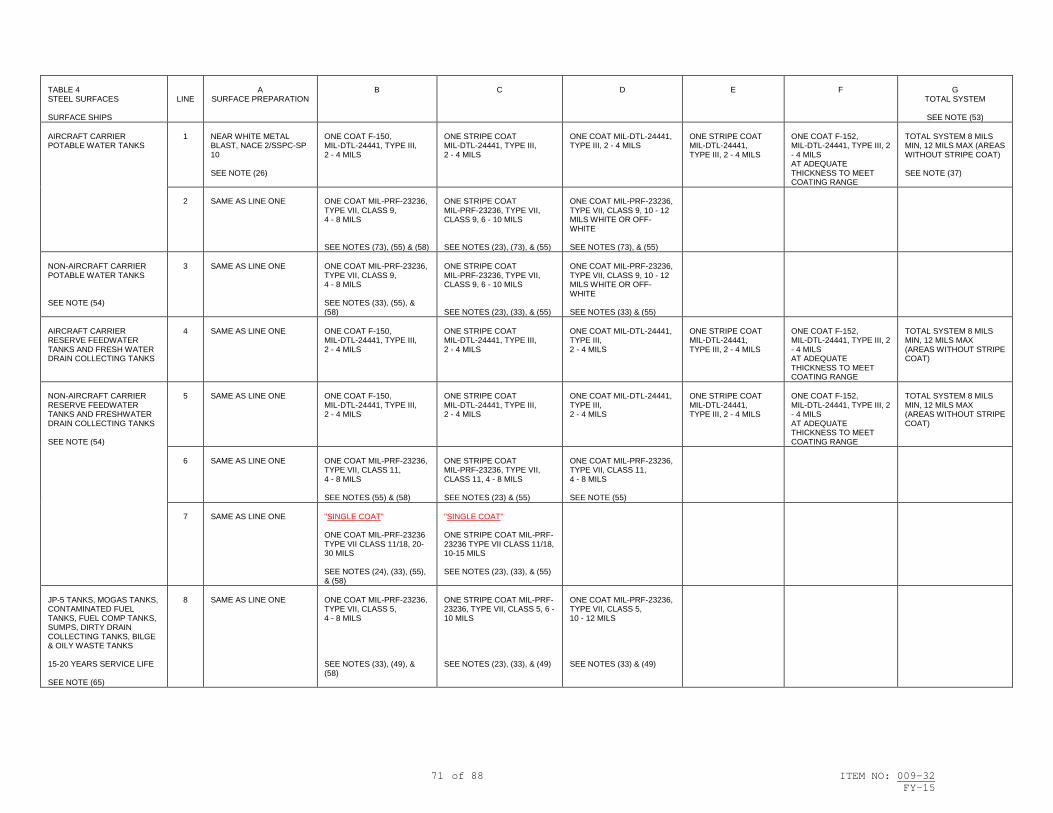
71 of 88 ITEM NO: 009-32 FY-15
TABLE 4 STEEL SURFACES SURFACE SHIPS
LINE
A
SURFACE PREPARATION
B
C
D
E
F
G
TOTAL SYSTEM
SEE NOTE (53) AIRCRAFT CARRIER POTABLE WATER TANKS
1
NEAR WHITE METAL BLAST, NACE 2/SSPC-SP 10 SEE NOTE (26)
ONE COAT F-150, MIL-DTL-24441, TYPE III, 2 - 4 MILS
ONE STRIPE COAT MIL-DTL-24441, TYPE III, 2 - 4 MILS
ONE COAT MIL-DTL-24441, TYPE III, 2 - 4 MILS
ONE STRIPE COAT MIL-DTL-24441, TYPE III, 2 - 4 MILS
ONE COAT F-152, MIL-DTL-24441, TYPE III, 2 - 4 MILS AT ADEQUATE THICKNESS TO MEET COATING RANGE
TOTAL SYSTEM 8 MILS MIN, 12 MILS MAX (AREAS WITHOUT STRIPE COAT) SEE NOTE (37)
2
SAME AS LINE ONE
ONE COAT MIL-PRF-23236, TYPE VII, CLASS 9, 4 - 8 MILS SEE NOTES (73), (55) & (58)
ONE STRIPE COAT MIL-PRF-23236, TYPE VII, CLASS 9, 6 - 10 MILS SEE NOTES (23), (73), & (55)
ONE COAT MIL-PRF-23236, TYPE VII, CLASS 9, 10 - 12 MILS WHITE OR OFF-WHITE SEE NOTES (73), & (55)
NON-AIRCRAFT CARRIER POTABLE WATER TANKS SEE NOTE (54)
3
SAME AS LINE ONE
ONE COAT MIL-PRF-23236, TYPE VII, CLASS 9, 4 - 8 MILS SEE NOTES (33), (55), & (58)
ONE STRIPE COAT MIL-PRF-23236, TYPE VII, CLASS 9, 6 - 10 MILS SEE NOTES (23), (33), & (55)
ONE COAT MIL-PRF-23236, TYPE VII, CLASS 9, 10 - 12 MILS WHITE OR OFF-WHITE SEE NOTES (33) & (55)
AIRCRAFT CARRIER RESERVE FEEDWATER TANKS AND FRESH WATER DRAIN COLLECTING TANKS
4
SAME AS LINE ONE
ONE COAT F-150, MIL-DTL-24441, TYPE III, 2 - 4 MILS
ONE STRIPE COAT MIL-DTL-24441, TYPE III, 2 - 4 MILS
ONE COAT MIL-DTL-24441, TYPE III, 2 - 4 MILS
ONE STRIPE COAT MIL-DTL-24441, TYPE III, 2 - 4 MILS
ONE COAT F-152, MIL-DTL-24441, TYPE III, 2 - 4 MILS AT ADEQUATE THICKNESS TO MEET COATING RANGE
TOTAL SYSTEM 8 MILS MIN, 12 MILS MAX (AREAS WITHOUT STRIPE COAT)
NON-AIRCRAFT CARRIER RESERVE FEEDWATER TANKS AND FRESHWATER DRAIN COLLECTING TANKS SEE NOTE (54)
5
SAME AS LINE ONE
ONE COAT F-150, MIL-DTL-24441, TYPE III, 2 - 4 MILS
ONE STRIPE COAT MIL-DTL-24441, TYPE III, 2 - 4 MILS
ONE COAT MIL-DTL-24441, TYPE III, 2 - 4 MILS
ONE STRIPE COAT MIL-DTL-24441, TYPE III, 2 - 4 MILS
ONE COAT F-152, MIL-DTL-24441, TYPE III, 2 - 4 MILS AT ADEQUATE THICKNESS TO MEET COATING RANGE
TOTAL SYSTEM 8 MILS MIN, 12 MILS MAX (AREAS WITHOUT STRIPE COAT)
6
SAME AS LINE ONE
ONE COAT MIL-PRF-23236, TYPE VII, CLASS 11, 4 - 8 MILS SEE NOTES (55) & (58)
ONE STRIPE COAT MIL-PRF-23236, TYPE VII, CLASS 11, 4 - 8 MILS SEE NOTES (23) & (55)
ONE COAT MIL-PRF-23236, TYPE VII, CLASS 11, 4 - 8 MILS SEE NOTE (55)
7
SAME AS LINE ONE
"SINGLE COAT" ONE COAT MIL-PRF-23236 TYPE VII CLASS 11/18, 20-30 MILS SEE NOTES (24), (33), (55), & (58)
"SINGLE COAT" ONE STRIPE COAT MIL-PRF-23236 TYPE VII CLASS 11/18, 10-15 MILS SEE NOTES (23), (33), & (55)
JP-5 TANKS, MOGAS TANKS, CONTAMINATED FUEL TANKS, FUEL COMP TANKS, SUMPS, DIRTY DRAIN COLLECTING TANKS, BILGE & OILY WASTE TANKS 15-20 YEARS SERVICE LIFE SEE NOTE (65)
8
SAME AS LINE ONE
ONE COAT MIL-PRF-23236, TYPE VII, CLASS 5, 4 - 8 MILS SEE NOTES (33), (49), & (58)
ONE STRIPE COAT MIL-PRF-23236, TYPE VII, CLASS 5, 6 - 10 MILS SEE NOTES (23), (33), & (49)
ONE COAT MIL-PRF-23236, TYPE VII, CLASS 5, 10 - 12 MILS SEE NOTES (33) & (49)

72 of 88 ITEM NO: 009-32 FY-15
TABLE 4 STEEL SURFACES SURFACE SHIPS
LINE
A
SURFACE PREPARATION
B
C
D
E
F
G
TOTAL SYSTEM
SEE NOTE (53) JP-5 TANKS, MOGAS TANKS, CONTAMINATED FUEL TANKS, FUEL COMP TANKS, SUMPS, DIRTY DRAIN COLLECTING TANKS, BILGE & OILY WASTE TANKS 10-12 YEARS SERVICE LIFE SEE NOTE (65)
9
NEAR WHITE METAL BLAST, NACE 2/SSPC-SP 10 SEE NOTE (38)
SAME AS LINE 8
SAME AS LINE 8
SAME AS LINE 8
10
SAME AS LINE ONE
"SINGLE COAT" ONE COAT MIL-PRF-23236 TYPE VII CLASS 5/18, 20-30 MILS SEE NOTES (24), (33), & (58)
"SINGLE COAT" ONE STRIPE COAT MIL-PRF-23236 TYPE VII CLASS 5/18, 10-15 MILS SEE NOTES (23) & (33)
CHT/MSD TANKS
11
SAME AS LINE 9
ONE COAT MIL-PRF-23236, TYPE VII, CLASS 13, 4 - 8 MILS SEE NOTES (33) & (58)
ONE STRIPE COAT MIL-PRF-23236, TYPE VII, CLASS 13, 6 - 10 MILS SEE NOTES (23) & (33)
ONE COAT MIL-PRF-23236, TYPE VII, CLASS 13, 10 - 12 MILS SEE NOTE (33)
12
SAME AS LINE 9
"SINGLE COAT" ONE COAT MIL-PRF-23236, TYPE VII CLASS 13/18, 20-30 MILS SEE NOTES (24), (33), & (58)
"SINGLE COAT" ONE STRIPE COAT MIL-PRF-23236, TYPE VII CLASS 13/18, 10-15 MILS SEE NOTES (23) & (33),
BALLAST TANKS, FLOODABLE VOIDS (SUBSTRATE TEMPERATURE 50 DEGREES FAHRENHEIT & ABOVE) EDGE RETENTIVE-EXTENDED SERVICE LIFE 15-20 YEARS (MORE STRINGENT HUMIDITY REQUIREMENTS)
13
SAME AS LINE ONE
"SINGLE COAT" ONE COAT MIL-PRF-23236 TYPE VII CLASS 7/18, 20-30 MILS SEE NOTES (24), (33), & (58)
"SINGLE COAT" ONE STRIPE COAT MIL-PRF-23236 TYPE VII CLASS 7/18, 10-15 MILS SEE NOTES (23) & (33)
BALLAST TANKS, FLOODABLE VOIDS (SUBSTRATE TEMPERATURE 50 DEGREES FAHRENHEIT & ABOVE) EDGE RETENTIVE SERVICE LIFE 10 - 12 YEARS (LESS STRINGENT HUMIDITY REQUIREMENTS)
14
SAME AS LINE 9
"SINGLE COAT" ONE COAT MIL-PRF-23236 TYPE VII CLASS 7/18, 20-30 MILS SEE NOTES (24), (33), & (58)
"SINGLE COAT" ONE STRIPE COAT MIL-PRF-23236 TYPE VII CLASS 7/18, 10-15 MILS SEE NOTES (23) & (33)
BALLAST TANKS, FLOODABLE VOIDS (USE ONLY WHEN SUBSTRATE TEMPERATURE CANNOT BE MAINTAINED ABOVE 50 DEGREES FAHRENHEIT) NORMAL 5 - 7 YEARS SERVICE LIFE
15
NEAR WHITE METAL BLAST, NACE 2/SSPC-SP 10
ONE COAT MIL-PRF-23236, CLASS 5 OR 7, GRADE A OR B, 4 - 8 MILS SEE NOTE (58)
ONE STRIPE COAT MIL-PRF-23236, CLASS 5 OR 7, GRADE A OR B, 4 - 8 MILS
ONE COAT MIL-PRF-23236, CLASS 5 OR 7, GRADE A OR B, 4 - 8 MILS
PEAK TANKS EDGE RETENTIVE-EXTENDED SERVICE LIFE 15-20 YEARS (MORE STRINGENT HUMIDITY REQUIREMENTS)
16
SAME AS LINE ONE
ONE COAT MIL-PRF-23236, TYPE VII CLASS 7, 4 - 8 MILS SEE NOTES (33) & (58)
ONE STRIPE COAT MIL-PRF-23236, TYPE VII CLASS 7, 6 - 10 MILS SEE NOTES (23) & (33)
ONE COAT MIL-PRF-23236, TYPE VII CLASS 7, 10 - 12 MILS SEE NOTE (33)
17
SAME AS LINE ONE
SAME AS LINE 14
SAME AS LINE 14

73 of 88 ITEM NO: 009-32 FY-15
TABLE 4 STEEL SURFACES SURFACE SHIPS
LINE
A
SURFACE PREPARATION
B
C
D
E
F
G
TOTAL SYSTEM
SEE NOTE (53) PEAK TANKS EDGE RETENTIVE SERVICE LIFE 10 - 12 YEARS (LESS STRINGENT HUMIDITY REQUIREMENTS)
18
SAME AS LINE 9
SAME AS LINE 16
SAME AS LINE 16
SAME AS LINE 16
19
SAME AS LINE 9
SAME AS LINE 14
SAME AS LINE 14
CHAIN LOCKERS AND NON-FLOODABLE VOIDS
20
NEAR WHITE METAL BLAST, NACE 2/SSPC-SP 10
"SINGLE COAT" ONE COAT MIL-PRF-23236, TYPE VII, CLASS 7/18, 20-30 MILS SEE NOTES (24), (33) & (58)
"SINGLE COAT" ONE STRIPE COAT MIL-PRF-23236, TYPE VII, CLASS 7/18, 10-15 MILS SEE NOTES (23) & (33)
CATAPULT WING VOIDS AND CATAPULT EXHAUST BLOWDOWN TRUNKS
21
SAME AS LINE 9
ONE COAT MIL-PRF-23236, TYPE VI, CLASS 5 OR 7, 4 - 8 MILS SEE NOTES (33) & (49)
ONE STRIPE COAT MIL-PRF-23236, TYPE VI, CLASS 5 OR 7, 4 - 8 MILS SEE NOTES (33) & (49)
ONE COAT MIL-PRF-23236, TYPE VI, CLASS 5 OR 7, 4 - 8 MILS SEE NOTES (33) & (49)
BARRICADE STANCHIONS AND WELLS, CATAPULT JET BLAST DEFLECTOR PITS, AND ASSOCIATED VOID SPACES
22
SAME AS LINE 9
ONE COAT MIL-PRF-23236, TYPE VI, CLASS 5, 4 - 8 MILS SEE NOTES (33) & (49)
ONE STRIPE COAT MIL-PRF-23236, TYPE VI, CLASS 5, 4 - 8 MILS SEE NOTES (33) & (49)
ONE COAT MIL-PRF-23236, TYPE VI, CLASS 5, 4 - 8 MILS SEE NOTES (33), (35) & (49)

74 of 88 ITEM NO: 009-32 FY-15
TABLE 4 ALUMINUM SURFACES SURFACE SHIPS
LINE
A
SURFACE PREPARATION
B
C
D
E
F
G
TOTAL SYSTEM
SEE NOTE (53) TANKS AND VOIDS
23
NEAR WHITE METAL BLAST, USING GARNET, ALUMINUM OXIDE, CRUSHED GLASS OR BLACK WALNUT SHELLS
SAME AS FOR STEEL
SAME AS FOR STEEL
SAME AS FOR STEEL
SAME AS FOR STEEL
SAME AS FOR STEEL
SAME AS FOR STEEL

75 of 88 ITEM NO: 009-32 FY-15
TABLE 5 VARIOUS LOCATIONS SURFACE SHIPS
LINE
A
SURFACE PREPARATION
B
C
D
E
F
TOTAL SYSTEM
SEE NOTE (53)
G
DESIGNATIONS & MARKINGS
UNHEATED PIPING, FITTINGS, VALVES
1
HAND TOOL CLEAN, SSPC-SP 2
2 COATS F-84, ALKYD ZINC MOLYBDATE, TT-P-645, 1.5 - 3 MILS/COAT
2 COATS OF BILGE FINISH COAT TO MATCH SURROUNDING SURFACES, INCLUDING LAGGED SURFACES
ONE COAT MIL-PRF-24635, 2 - 3 MILS, FOR COLOR CODED SYSTEMS
MACHINERY, GAGEBOARDS; UNHEATED FERROUS MACHINERY EXTERNAL SURFACES
2
POWER TOOL CLEAN, SSPC-SP 3
SAME AS LINE ONE
ONE COAT F-111, MIL-DTL-15090, 1.5 - 3 MILS - OR - ONE COAT NO. 26307 (FED STD 595), MIL-PRF-24635, 2 - 3 MILS
IF REQUIRED FOR HIDING, ONE ADDITIONAL COAT: F-111, MIL-DTL-15090, 1.5 - 3 MILS - OR - NO. 26307 (FED STD 595), MIL-PRF-24635, 2 - 3 MILS
UNINSULATED SIDE OF BULKHEAD OR SHELL ADJACENT TO SEA OR AC BOUNDARY (FOR INTERIOR COMPARTMENTS ONLY)
3
POWER TOOL CLEAN TO BARE METAL, SSPC-SP 11
ONE COAT HEMPEL HEMPADUR 45880, 4 - 6 MILS
ONE COAT HEMPEL ANTI-CONDENS 617US-10000, 50 - 60 MILS
4
SAME AS LINE 3
ONE COAT F-84, ALKYD ZINC MOLYBDATE, TT-P-645, 1.5 - 3 MILS - OR - ONE COAT MIL-PRF-23236, TYPE V VI, OR VII, 4 - 8 MILS
ONE COAT TEMP-COAT 101, 20 - 22 MILS
ONE COAT TEMP-COAT 101, 20 - 22 MILS
ONE COAT TEMP-COAT 101, 20 - 22 MILS
5
SAME AS LINE 3
SAME AS LINE 4
ONE COAT MASCOAT DELTA-T MARINE, 20-22 MILS
ONE COAT MASCOAT DELTA-T MARINE, 20-22 MILS
ONE COAT MASCOAT DELTA-T MARINE, 20-22 MILS
6
SAME AS LINE 3
SAME AS LINE 4
ONE COAT KEFA AIRLESS 8125, 50 - 60 MILS
BOILERS & ECONOMIZERS (EXCEPT PARTS USED FOR HEAT TRANSFER), MACHINERY CASINGS, FERROUS SHEET METAL
7
SAME AS LINE 3
ONE COAT AMERON AMERCOAT 892HS, 2 - 3 MILS SEE NOTE (39)
8
SAME AS LINE 3
2 COATS OF TT-P-28 SUFFICIENT TO COVER THE PROFILE
STEAM, RESERVE FEEDWATER, BOTTOM/ SURFACE BLOW & BOILER PRESSURE VESSEL PIPING IN PREPARATION FOR ULTRASONIC MEASUREMENTS
9
POWER TOOL CLEAN TO BARE METAL, SSPC-SP 11, USING STAINLESS STEEL WIRE BRUSHES, STAINLESS STEEL PADS, OR ABRASIVE SANDING DISCS (ANSI/BHMA B74.18)
ELECTRICAL EQUIPMENT, ELECTRONIC EQUIPMENT
10
SAME AS LINE ONE
2 COATS F-84, TT-P-645, ALKYD ZINC MOLYBDATE, 1.5 - 3 MILS/COAT
2 COATS F-111, MIL-DTL-15090, 1.5 - 3 MILS/COAT
CABLE, INTERIOR
11
SAME AS LINE ONE
2 COATS WATER-BASED LATEX PER MIL-PRF-24596, 2 - 4 MILS/COAT
2 COATS MIL-DTL-24607 CHLORINATED ALKYD 1.5 - 3 MILS/COAT (FOR COLOR MATCH IF REQUIRED)
CABLE, EXTERIOR (OTHER THAN PVC, LOW SMOKE)
12
SAME AS LINE ONE
SAME AS LINE 11
2 COATS MIL-PRF-24763, TYPE II, CLASS 2, 2 – 4 MILS/COAT --OR— ONE COAT MIL-PRF-24635 (LOW SOLAR ABSORPTION ONLY) TO MATCH SURROUNDING AREA, 2 - 3 MILS

76 of 88 ITEM NO: 009-32 FY-15
TABLE 5 VARIOUS LOCATIONS SURFACE SHIPS
LINE
A
SURFACE PREPARATION
B
C
D
E
F
TOTAL SYSTEM
SEE NOTE (53)
G
DESIGNATIONS & MARKINGS
ANCHOR (SURFACE SHIP BOW ANCHORS) FOR ANCHORS BELOW LOWER BOOTTOPPING LIMIT, SEE NOTE (13)
13
NEAR WHITE METAL BLAST, NACE 2/SSPC-SP 10 SEE NOTES (14) & (21)
ONE COAT MIL-PRF-23236, TYPE V OR VI, CLASS 5 OR 7, 4 - 8 MILS - OR - ONE COAT MIL-PRF-23236, CLASS 5 OR 7, TYPE VII, 4 - 8 MILS
ONE COAT MIL-PRF-23236, TYPE V OR VI, CLASS 5 OR 7, 4 - 8 MILS - OR - ONE COAT MIL-PRF-23236, TYPE VII, CLASS 5 OR 7, 10 - 12 MILS
ONE COAT HAZE GRAY, NO. 26270 (FED STD 595), MIL-PRF-24635 (LOW SOLAR ABSORPTION ONLY), 2 - 3 MILS
ANCHOR CHAIN
14
COMMERCIAL BLAST CLEAN, SSPC-SP 6 SEE NOTES (14) & (21)
ONE COAT MIL-PRF-24635, TYPE V OR VI --OR-- ONE COAT MIL-PRF-23236 TYPE VI OR VII, 4-6 MILS
ONE COAT MIL-PRF-24635, TYPE V OR VI, 4-6 MILS
10 MILS MIN, 12 MILS MAX
MIL-PRF-24635, TYPE V OR VI SEE NOTE (15)
INTERIOR GALVANIZED SURFACES
15
BRUSH-OFF BLAST, SSPC-SP 7 - OR - POWER TOOL CLEAN, SSPC-SP 3
ONE COAT WATER-BASED INTERIOR LATEX, MIL-PRF-24596, 2 - 4 MILS
TOPCOAT TO MATCH SURROUNDING AREA
EXTERIOR GALVANIZED SURFACES
16
SAME AS LINE 15
ONE COAT MIL-PRF-23236 TYPE V CLASS 5 OR 7 -OR- MIL-DTL-24441, 1-2 MILS
ONE COAT MIL-PRF-24763, 2 - 4 MILS
TOPCOAT TO MATCH SURROUNDING AREA
EXHAUST PIPE EXTERIOR
17
NEAR WHITE METAL BLAST, NACE 2/SSPC-SP 10
ONE COAT AMERCOAT 892HS, HAZE GRAY #26270, 2 - 3 MILS - OR - 2 COATS OF TT-P-28 SUFFICIENT TO COVER THE PROFILE SEE NOTES (39) & (42)
ELEVATED TEMPERATURE PIPING AND MACHINERY, 125-200F
18
SAME AS LINE 17
ONE COAT MIL-DTL-24441 TYPE IV, 4-6 MILS
HIGH TEMPERATURE PIPING AND MACHINERY, 200-400F
19
SAME AS LINE 17
ONE COAT AMERCOAT 892HS, HAZE GRAY #26270, 2 - 3 MILS SEE NOTE (39)
HIGH TEMPERATURE PIPING AND MACHINERY, 400-1200F
20
SAME AS LINE 17
2 COATS OF TT-P-28 SUFFICIENT TO COVER THE PROFILE
PCMS (REPAIRS) SEE NOTE (57)
21
STRIP PAINT, USING "PEEL-AWAY-7" - OR - PLASTIC MEDIA BLASTER - OR - SODIUM BICARBONATE MEDIA BLASTER SEE REPAIR & INSTALLATION METHODS, RIM 05T1-99
ONE COAT HAZE GRAY, MIL-PRF-24763 (LOW SOLAR ABSORPTION ONLY), 2 - 4 MILS (TOP COAT OF PCMS) SEE NOTES (45) & (74)
PCMS (NEW TILE INSTALLATION)
22
NEAR WHITE METAL BLAST, NACE 2/SSPC-SP 10 - OR - POWER TOOL CLEAN TO BARE METAL, SSPC-SP 11
ONE COAT MIL-PRF-23236 TYPE V OR VI, CLASS 5 OR 7, 4 - 8 MILS
ONE COAT MIL-PRF-23236, TYPE V OR VI, CLASS 5 OR 7, 4 - 8 MILS
SAME AS LINE 21

77 of 88 ITEM NO: 009-32 FY-15
TABLE 5 VARIOUS LOCATIONS SURFACE SHIPS
LINE
A
SURFACE PREPARATION
B
C
D
E
F
TOTAL SYSTEM
SEE NOTE (53)
G
DESIGNATIONS & MARKINGS
ARRESTING GEAR SHEAVE FOUNDATIONS (NON-MACHINERY ROOMS)
23
SSPC-SP 1 -- & -- SPONGEJET TO NEAR WHITE METAL BLAST, NACE 2/SSPC-SP 10 -- & -- SSPC-SP 1 (STEAM CLEAN) -- & -- SPONGEJET TO NEAR WHITE METAL BLAST, NACE 2/SSPC-SP 10
ONE COAT MIL-PRF-23236, TYPE VII, CLASS 5, 4 - 8 MILS (BRUSH APPLY ONLY) SEE NOTES (33) & (49)
ONE STRIPE COAT MIL-PRF-23236, TYPE VII, CLASS 5, 6 - 10 MILS SEE NOTES (23), (33) & (49)
ONE COAT MIL-PRF-23236, TYPE VII, CLASS 5, 10 - 12 MILS SEE NOTES (33) & (49)
24
SAME AS LINE 20
ONE COAT MIL-PRF-23236, TYPE VII CLASS 17, 6 – 8 MILS (BRUSH APPLY ONLY)
ONE STRIPE COAT MIL-PRF-23236, TYPE VII CLASS 17, 6 – 8 MILS SEE NOTE (23)
ONE FULL COAT MIL-PRF-23236 TYPE VII, CLASS 17, 6 – 8 MILS
ARRESTING GEAR SHEAVE FOUNDATIONS (MACHINERY ROOMS)
25
POWER TOOL CLEAN TO BARE METAL, SSPC-SP 11
ONE COAT MIL-PRF-23236, TYPE VI, CLASS 5 OR 7, 4-8 MILS
ONE STRIPE COAT MIL-PRF-23236, TYPE VI, CLASS 5 OR 7, 4-8 MILS
ONE COAT MIL-PRF-23236, TYPE VI, CLASS 5 OR 7, 4-8 MILS
POWDERCOATING FOR EXTERIOR APPLICATIONS AND INTERIOR DRY APPLICATIONS OF REMOVABLE PARTS
26
SAME AS LINE 17
ONE COAT MIL-PRF-24712
POWDERCOATING FOR INTERIOR WET OR IMMERSION APPLICATION AREAS
27
SAME AS LINE 17
ONE COAT MIL-PRF-23236, TYPE VIII

78 of 88 ITEM NO: 009-32 FY-15
TABLE 6 STEEL SURFACES SUBMARINES
LINE
A
SURFACE PREPARATION
B
PRIMER
C
D
E
KEEL TO MAX BEAM
F
MAX BEAM TO UPPER BOOTTOP
G
DRAFT MARKS
EXTERIOR SURFACES (KEEL TO UPPER BOOTTOP) (NON-SHT SURFACES BELOW UPPER BOOTTOP)
1 NEAR WHITE METAL BLAST, NACE 2/SSPC-SP 10 - OR - WATERJETTING TO NACE/SSPC WJ-2/L
ONE COAT MIL- PRF-23236, TYPE V OR VI CLASS 5 OR 7, 4 - 8 MILS --OR— ONE AC COATS MIL-PRF-24647 TYPE I OR II, 5 - 7 MILS --OR— ONE COAT MIL-DTL-24441 TYPE IV, F-150, , 5 - 7 MILS SEE NOTES (1A), (4A), & (35A)
ONE STRIPE COAT MIL- PRF-23236, TYPE V OR VI CLASS 5 OR 7, 4 - 8 MILS --OR— ONE AC STRIPE COAT MIL-PRF-24647 TYPE I OR II, 5 - 7 MILS --OR— ONE STRIPE COAT MIL-DTL-24441 TYPE IV, 5 - 7 MILS SEE NOTES (1A), (4A), & (35A)
ONE COAT MIL- PRF-23236, TYPE V OR VI CLASS 5 OR 7, 4 - 8 MILS --OR— ONE AC COAT MIL-PRF-24647 TYPE I OR II, 5 - 7 MILS --OR— ONE COAT MIL-DTL-24441 TYPE IV, F-153, 5 - 7 MILS SEE NOTES (1A), (4A), & (35A)
2 AF COATS MIL-PRF-24647, TYPE I OR II, 5 - 7 MILS/COAT SEE NOTES (2A) & (4A)
2 AF COATS MIL-PRF-24647, TYPE I OR II BLACK, 5 - 7 MILS/COAT SEE NOTES (3A) & (4A)
ONE COAT MIL-DTL-24631 F-186 --OR-- ONE COAT MIL-DTL-24441 TYPE IV, F-152 --OR-- ONE AC COAT MIL-PRF-23236, WHITE, 3-4 MILS SEE NOTE (5A)
NON-SHT, EXTERIOR SURFACES ABOVE THE UPPER BOOTTOP (INCLUDES DSRV/SRC SEATING SURFACES)
2
SAME AS LINE ONE
ONE COAT MIL- PRF-23236, TYPE V OR VI CLASS 5 OR 7, 4 - 8 MILS --OR-- ONE COAT AC MIL-PRF-24647, TYPE I OR II, 5 - 7 MILS SEE NOTES (1A), (32A), & (35A)
ONE STRIPE COAT MIL- PRF-23236, TYPE V OR VI CLASS 5 OR 7, 4 - 8 MILS --OR-- ONE STRIPE COAT AC MIL-PRF-24647, TYPE I OR II, 5 - 7 MILS SEE NOTES (1A), (32A), & (35A)
ONE COAT MIL- PRF-23236, TYPE V OR VI CLASS 5 OR 7, 4 - 8 MILS --OR-- ONE COAT AC MIL-PRF-24647, TYPE I OR II, 5 - 7 MILS FINAL COAT TO BE BLACK SEE NOTES (1A), (32A), & (35A)
3
SAME AS LINE ONE
ONE COAT MIL-DTL-24441 TYPE IV, F-150, 5 - 7 MILS SEE NOTES (1A), (32A), & (35A)
ONE STRIPE COAT MIL-DTL-24441 TYPE IV, 5 - 7 MILS SEE NOTES (1A), (32A), & (35A)
ONE COAT MIL-DTL-24441 TYPE IV, F-153, 5 - 7 MILS SEE NOTES (1A), (32A), & (35A)
FOR MOORED TRAINING SHIPS ONLY; EXTERIOR SURFACES ABOVE THE UPPER BOOTTOP (NON-IMMERSION SURFACES ONLY)
4
SAME AS LINE ONE
ONE COAT MIL-PRF-23236, TYPE V OR VI CLASS 5 OR 7, 4 - 8 MILS --OR-- ONE COAT MIL-DTL-24441, TYPE IV 5 - 7 MILS SEE NOTES (1A) & (32A)
ONE STRIPE COAT MIL-PRF-23236, TYPE V OR VI CLASS 5 OR 7, 4 - 8 MILS --OR-- ONE STRIPE COAT MIL-DTL-24441, TYPE IV 5 - 7 MILS SEE NOTES (1A) & (32A)
ONE COAT MIL-PRF-23236, TYPE V OR VI CLASS 5 OR 7, 4 - 8 MILS --OR-- ONE COAT MIL-DTL-24441, TYPE IV 5 - 7 MILS SEE NOTES (1A) & (32A)
UPPER BOOTTOP TO TOP OF SAIL ONLY: ONE COAT MIL-PRF-24635 NO. 27038, 2-4 MILS -&- ONE COAT MIL-PRF-24667, TYPE I OR X, COMP G
UNTILED (NON-SHT COVERED) FOOT TRAFFIC AREAS TO BE COVERED WITH NONSKID PAINT (ALL CLASSES OF SUBMARINES)
5
SAME AS LINE ONE
ONE COAT MIL-DTL-24441 TYPE IV F-150, 5 - 7 MILS SEE NOTE (32A)
ONE STRIPE COAT MIL-DTL-24441 TYPE IV, 5 - 7 MILS SEE NOTE (32A)
ONE COAT MIL-DTL-24441 TYPE IV, F-153, 5 - 7 MILS SEE NOTE (32A)
NONSKID: MIL-PRF-24667, TYPE I OR X, COMP G SEE NOTE (44A)
6
SAME AS LINE ONE
ONE COAT MIL- PRF-23236, TYPE V OR VI CLASS 5 OR 7, 4 - 8 MILS --OR— ONE COAT AC MIL-PRF-24647, TYPE I OR II, 5 - 7 MILS SEE NOTES (3A) & (32A)
ONE STRIPE COAT MIL- PRF-23236, TYPE V OR VI CLASS 5 OR 7, 4 - 8 MILS --OR— ONE STRIPE COAT AC MIL-PRF-24647, TYPE I OR II, 5 - 7 MILS SEE NOTES (3A) & (32A)
ONE COAT MIL- PRF-23236, TYPE V OR VI CLASS 5 OR 7, 4 - 8 MILS --OR— ONE COAT AC MIL-PRF-24647, TYPE I OR II, 5 - 7 MILS FINAL COAT TO BE BLACK SEE NOTES (3A) & (32A)
SAME AS LINE 5
7
INTENTIONALLY LEFT BLANK
8
INTENTIONALLY LEFT BLANK
79 of 88 ITEM NO: 009-32 FY-15
TABLE 6 STEEL SURFACES SUBMARINES
LINE
A
SURFACE PREPARATION
B
PRIMER
C
D
E
KEEL TO MAX BEAM
F
MAX BEAM TO UPPER BOOTTOP
G
DRAFT MARKS
9
INTENTIONALLY LEFT BLANK
10
INTENTIONALLY LEFT BLANK
11
INTENTIONALLY LEFT BLANK

80 of 88 ITEM NO: 009-32 FY-15
TABLE 6 GRP FIBERGLASS SURFACES SUBMARINES
LINE
A
SURFACE PREPARATION
B
PRIMER
C
D
E
KEEL TO MAX BEAM
F
MAX BEAM TO UPPER BOOTTOP
G
DRAFT MARKS
UNBOOTED GRP BOW DOMES ABOVE UPPER BOOTTOP SEE NOTE (34A)
12
LOW PRESSURE WATER CLEAN (LP WC) SEE NOTE (42A)
ONE COAT MIL-DTL-24441, TYPE IV, F-150, 4 - 6 MILS -- & -- ONE COAT MIL-DTL-24441 TYPE IV, F-153 OR F-154, 4 - 6 MILS --OR-- 2 COATS MIL-PRF-24647 4 - 6 MIL/COAT --OR-- 2 COATS MIL-PRF-23236 TYPE V OR VI, CLASS 5 OR 7, 4 - 6 MILS/COAT SEE NOTES (32A) & (38A)
UNBOOTED GRP BOW DOMES BELOW UPPER BOOTTOP SEE NOTE (34A)
13
SAME AS LINE 12
ONE COAT MIL-DTL-24441, TYPE IV, F-150, 4 - 6 MILS --OR-- ONE COAT MIL-PRF-24647 4 - 6 MIL/COAT DARK GRAY SEE NOTE (4A)
TWO COATS AF MIL-PRF-24647, TYPE I, CLASS 3, 4 - 6 MIL/COAT SEE NOTES (2A), (4A), & (38A)
TWO COATS AF MIL-PRF-24647, TYPE I, CLASS 3, 4 - 6 MIL/COAT SEE NOTES (3A), (4A), & (38A)
BOOTED GRP BOW DOMES ABOVE UPPER BOOTTOP SEE NOTE (34A)
14
LOW PRESSURE WATER CLEAN (LP WC) SEE NOTE (43A)
PRIOR TO INSTALLING THE BOOT - ONE COAT MIL-DTL-24441, TYPE IV, F-150, 2-4 MILS AFTER BOOT INSTALLATION ONE COAT NAVY FORMULA 187, 2-3 MILS SEE NOTES (38A) & (46A)
BOOTED GRP BOW DOMES BELOW UPPER BOOTTOP SEE NOTE (34A)
15
SAME AS LINE 14
PRIOR TO INSTALLING THE BOOT - ONE COAT MIL-DTL-24441, TYPE IV, F-150, 2-4 MILS AFTER BOOT INSTALLATION ONE COAT NAVY FORMULA 184, 2-3 MILS
SAME AS LINE 13
SAME AS LINE 13
INTERIOR SURFACES OF RUDDERS, PLANES, STABILIZERS (SYNTACTIC FILLED VOIDS)
16
HAND TOOL CLEAN, SSPC-SP 2
2 COATS TT-P-645 F-84 (PRIMER), 1-2 MILS/COAT -OR- ONE COAT PRIMER MIL-PRF-23236, TYPE V OR VI, 4-6 MILS -OR- ONE COAT MIL-DTL-24441, TYPE IV, F-150, 4-6 MILS
ONE STRIPE COAT TT-P-645, 1-2 MILS -OR- ONE STRIPE COAT MIL-PRF-23236, TYPE V OR VI, 4-6 MILS -OR- ONE STRIPE COAT MIL-DTL-24441, TYPE IV, 4-6 MILS

81 of 88 ITEM NO: 009-32 FY-15
TABLE 7 STEEL SURFACES SUBMARINES
LINE
A
SURFACE PREPARATION
B
PRIMER
C
D
E
BULKHEADS AND OVERHEADS
F
THERMAL INSULATION
G
BILGE AND TRUNK INTERIOR AREAS BELOW THE LOWER WALKING FLAT SEE NOTE (36A)
1
POWER TOOL CLEAN TO BARE METAL, SSPC-SP 11 SEE NOTE (6A)
ONE COAT MIL-PRF-23236, TYPE VII, CLASS 17, 5 - 7 MILS SEE NOTES (8A), (15A) & (28A)
ONE STRIPE COAT AND ONE FULL COAT MIL-PRF-23236, TYPE VII, CLASS 17, 5 - 7 MILS/COAT SEE NOTES (7A), (8A), (9A), (15A), (28A), (33A) & (37A)
2
SAME AS LINE ONE
ONE COAT MIL-DTL-24441, TYPE IV, F-150, 4-6 MILS SEE NOTES (15A) & (28A)
ONE STRIPE COAT AND ONE FULL COAT MIL-DTL-24441, TYPE IV, F-151 OR F-157, 4-6 MILS/COAT SEE NOTES (7A), (15A), (28A), & (33A)
3
SAME AS LINE ONE
ONE COAT MIL- PRF-23236, TYPE V OR VI, CLASS 5 OR 7, 4 - 8 MILS SEE NOTES (15A) & (28A)
ONE STRIPE COAT AND ONE FULL COAT MIL-PRF-23236, TYPE V OR VI, CLASS 5 OR 7, 4 - 8 MILS/COAT SEE NOTES (7A), (9A), (15A), (28A), & (33A)
WET SPACES (EXCEPT BILGES AND TRUNKS)
4
SAME AS LINE ONE
SAME AS LINE 2
SAME AS LINE 2
5
SAME AS LINE ONE
SAME AS LINE 3
SAME AS LINE 3
VRLA BATTERY COMPARTMENT
6
SAME AS LINE ONE
SAME AS LINE 2
ONE STRIPE COAT, MIL-DTL-24441, TYPE IV, F-151 or F-157, AND ONE FULL COAT, MIL-DTL-24441, TYPE IV, F-152, 4-6 MILS/COAT SEE NOTES (7A), (15A), (28A), & (33A)
VRLA BATTERY COMPARTMENT (SSBN/SSGN-726 CLASS)
7
NEAR WHITE METAL BLAST, NACE 2/SSPC-SP 10
“SINGLE COAT” ONE COAT MIL-PRF-23236 TYPE VII, CLASS 7/18, 20 – 30 MILS SEE NOTES (15A), (16A) & (40A)
“SINGLE COAT” ONE STRIPE COAT MIL-PRF-23236 TYPE VII, CLASS 7/18, 10 – 15 MILS SEE NOTES (15A) & (37A)
VA CLASS BATTERY COMPARTMENT (DECK AND BHDS UP TO 62” ABOVE TOP STEP OF DECK)
8
SAME AS LINE ONE
TEK-HAZ RED PRIME COAT, 16-20 MILS SEE NOTES (24A) & (28A)
TEK-HAZ GRAY TOPCOAT, 16-20 MILS SEE NOTES (24A), (28A), & (33A)
VA CLASS BATTERY COMPARTMENT (OVHD AND BHDS ABOVE 62” ABOVE TOP STEP OF DECK)
9
SAME AS LINE ONE
ONE COAT MIL-DTL-24441, TYPE IV, F-150, 4-6 MILS SEE NOTES (24A) & (28A)
2 COATS MIL-PRF-24635, TYPE II, CLASS 1, 4-6 MILS/ COAT SEE NOTES (24A), (28A), & (33A)

82 of 88 ITEM NO: 009-32 FY-15
TABLE 7 STEEL SURFACES SUBMARINES
LINE
A
SURFACE PREPARATION
B
PRIMER
C
D
E
BULKHEADS AND OVERHEADS
F
THERMAL INSULATION
G
TRUNK INTERIORS, UNINSULATED AREA ABOVE THE LOWER FLAT (INCLUDING UPPER HATCH COVER) SEE NOTE (36A)
10
POWER TOOL CLEAN TO BARE METAL, SSPC-SP 11 SEE NOTES (6A) & (13A)
SAME AS LINE ONE
ONE COAT MIL-PRF-23236, TYPE VII, CLASS 17, 5 - 7 MILS SEE NOTE (7A), (8A), (9A), (15A), (28A), (33A), & (37A)
11
SAME AS LINE 10
SAME AS LINE 2
ONE COAT MIL-DTL-24441, TYPE IV, F-151 OR F-157, 4-6 MILS SEE NOTES (7A), (15A), & (28A)
ONE COAT MIL-DTL-24607, 1-2 MILS SEE NOTES (7A), (9A), (10A), (11A), (12A), (28A) & (33A)
12
SAME AS LINE 10
SAME AS LINE 3
ONE COAT MIL-PRF-23236, TYPE V OR VI, CLASS 5 OR 7, 4 - 8 MILS SEE NOTES (7A), (9A), (15A), & (28A)
SAME AS LINE 11
TRUNK INTERIORS UNDER INSULATION ABOVE THE LOWER FLAT SEE NOTE (36A)
13
SAME AS LINE ONE
SAME AS LINE 2
ONE COAT MIL-DTL-24441, TYPE IV, CONTRASTING COLOR, 4-6 MILS SEE NOTES (7A), (15A), (28A), & (33A)
14
SAME AS LINE ONE
SAME AS LINE 3
ONE FULL COAT MIL-PRF-23236, TYPE V OR VI, CLASS 5 OR 7, 4 - 8 MILS SEE NOTES (7A), (15A), (28A), & (33A)
MACHINERY SPACES (ENGINE ROOMS AND AUXILIARY MACHINERY ROOMS) UNINSULATED PRESSURE HULL
15
SAME AS LINE ONE
SAME AS LINE 2
SAME AS LINE 11
2 COATS MIL-DTL-24607, 1-2 MILS/COAT SEE NOTES (7A), (9A), (10A), (11A), (28A) & (33A)
16
SAME AS LINE ONE
SAME AS LINE 3
SAME AS LINE 12
SAME AS LINE 15
MACHINERY SPACES (ENGINE ROOMS AND AUXILIARY MACHINERY ROOMS) PRESSURE HULL TO BE COVERED BY INSULATION
17
SAME AS LINE ONE
SAME AS LINE 2
SAME AS LINE 2
18
SAME AS LINE ONE
SAME AS LINE 3
SAME AS LINE 3
DECKS WITHOUT COVERINGS
19
SAME AS LINE ONE
ONE COAT MIL-DTL-24441, TYPE IV, 2-4 MILS SEE NOTES (7A), (15A), (25A), (28A), & (33A)
ONE COAT MIL-DTL-24441, TYPE IV, 2-4 MILS SEE NOTES (7A), (15A), (28A), & (33A)
20
SAME AS LINE ONE
SAME AS LINE 3
SAME AS LINE 14
21
SAME AS LINE ONE
ONE COAT TT-P-645, F-84, 1-2 MILS SEE NOTES (28A) & (33A)
2 COATS MIL-PRF-24635, 1-2 MILS/COAT SEE NOTES (7A), (28A), & (33A)

83 of 88 ITEM NO: 009-32 FY-15
TABLE 7 STEEL SURFACES SUBMARINES
LINE
A
SURFACE PREPARATION
B
PRIMER
C
D
E
BULKHEADS AND OVERHEADS
F
THERMAL INSULATION
G
DECKS WITH COVERINGS
22
SAME AS LINE ONE
ONE COAT MIL-DTL-24441, TYPE IV, F-150, 2 - 4 MILS -OR- ONE COAT MIL- PRF-23236, TYPE V OR VI, CLASS 5 OR 7, 4 - 8 MILS SEE NOTES (15A), (28A) & (33A)
23
SAME AS LINE ONE
SAME AS LINE 21
ENSOLITE INSULATION (OVERCOAT)
24
DETERGENT WASH AND RINSE
2 COATS MIL-DTL-24607, 1-2 MILS/COAT SEE NOTES (7A), (9A), (10A), (11A), (28A) & (33A)
POLYIMIDE INSULATION (OVERCOAT)
25
SAME AS LINE 24
SAME AS LINE 24
26
SAME AS LINE 24
2 COATS MIL-PRF-24596, 1-2 MILS/COAT -OR- 2 COATS F-25A, 1-2 MILS/COAT SEE NOTES (28A) & (33A)
DRY VOIDS
27
SAME AS LINE ONE
SAME AS LINE 3
SAME AS LINE 14
28
SAME AS LINE ONE
SAME AS LINE 19
SAME AS LINE 19

84 of 88 ITEM NO: 009-32 FY-15
TABLE 8 STEEL SURFACES SUBMARINES
LINE
A
SURFACE PREPARATION
B
PRIMER
C
D
E
F
G
TOTAL
POTABLE WATER TANKS
1
NEAR WHITE METAL BLAST, NACE 2/SSPC-SP 10 SEE NOTE (29A)
ONE COAT MIL-PRF-23236, TYPE VII, CLASS 9, 4 - 8 MILS SEE NOTES (15A), (17A), (39A), & (51A)
ONE STRIPE COAT MIL-PRF-23236, TYPE VII, CLASS 9, 6-10 MILS SEE NOTES (15A), (37A), (39A), & (51A)
ONE COAT MIL-PRF-23236, TYPE VII, CLASS 9, 10-12 MILS, WHITE OR OFF-WHITE SEE NOTES (15A), (27A), (39A), & (51A)
SEE NOTES (31A) & (34A) 2
SAME AS LINE ONE
ONE COAT MIL-DTL-24441, TYPE III, F-150, 2 - 4 MILS SEE NOTES (15A), (17A), & (21A)
ONE STRIPE COAT MIL-DTL-24441, TYPE III, 2 - 4 MILS SEE NOTES (15A), & (21A)
ONE COAT MIL-DTL-24441, TYPE III, 2 - 4 MILS SEE NOTES (15A) & (21A)
ONE STRIPE COAT MIL-DTL-24441, TYPE III, 2-4 MILS SEE NOTES (15A) & (21A)
ONE COAT MIL-DTL-24441, TYPE III, F-152, 2-4 MILS DFT AT ADEQUATE THICKNESS TO MEET COATING RANGE SEE NOTES (15A), (21A), & (27A)
TOTAL SYSTEM 8 -12 MILS (ON AREAS WITHOUT STRIPE COAT) SEE NOTE (22A)
RESERVE FEEDWATER TANKS SEE NOTES (31A) & (34A)
3
SAME AS LINE ONE
ONE COAT MIL-DTL-24441, TYPE III, F-150, 2 - 4 MILS SEE NOTES (15A), (17A), & (21A)
ONE STRIPE COAT MIL-DTL-24441 TYPE III F-152, 2 - 4 MILS SEE NOTES (15A) & (21A)
ONE COAT MIL-DTL-24441, TYPE III F-151, 2 - 4 MILS SEE NOTES (15A) & (21A)
ONE STRIPE COAT MIL-DTL-24441, TYPE III, F-150, 2 - 4 MILS SEE NOTES (15A) & (21A)
ONE COAT MIL-DTL-24441 TYPE III F-152, 2 - 4 MILS SEE NOTES (15A) & (21A)
TOTAL SYSTEM 8 MILS MIN
AUXILIARY TANKS, ACR HOLDING TANKS (MTS), DEPTH CONTROL TANKS, NFO EXPANSION TANK, SEAWATER EXPANSION TANK, SECONDARY SHIELD WATER OVERFLOW TANK (MTS), TRIM TANKS, UNHEATED WATER STORAGE TANK (MTS), WRT TANKS
4
SAME AS LINE ONE
"SINGLE COAT" ONE COAT MIL-PRF-23236, TYPE VII, CLASS 7/18, 20-30 MILS SEE NOTES (15A), (16A), (17A), (40A), (49A), & (50A)
"SINGLE COAT" ONE STRIPE COAT MIL-PRF-23236, TYPE VII, CLASS 7/18, 10-15 MILS SEE NOTES (15A), (37A), & (49A)
BILGE AND DRAIN COLLECTION TANKS SEE NOTE (25A)
5
SAME AS LINE ONE
ONE COAT MIL-PRF-23236, TYPE VII, CLASS 5, 4 - 8 MILS SEE NOTES (15A), (17A), (49A), & (50A)
ONE STRIPE COAT MIL-PRF-23236, TYPE VII, CLASS 5, 6 - 10 MILS SEE NOTES (15A), (37A), & (49A)
ONE COAT MIL-PRF-23236, TYPE VII, CLASS 5, 10 - 12 MILS SEE NOTES (15A) & (49A)
BOW TANK, BOW SONAR TANK, SONAR DOME AREA STEEL STRUCTURE (INCLUDES SONAR SPHERE, ITS SUPPORT STRUCTURE, AND FORWARD SIDE OF MBT BULKHEAD)
6
SAME AS LINE ONE
"SINGLE COAT" ONE COAT MIL-PRF-23236, TYPE VII, CLASS 7/18, 20-30 MILS SEE NOTES (17A), (18A), (19A), (40A), (49A), & (50A)
"SINGLE COAT" ONE STRIPE COAT MIL-PRF-23236, TYPE VII, CLASS 7/18, 10-15 MILS SEE NOTES (18A), (37A), & (49A)

85 of 88 ITEM NO: 009-32 FY-15
TABLE 8 STEEL SURFACES SUBMARINES
LINE
A
SURFACE PREPARATION
B
PRIMER
C
D
E
F
G
TOTAL
FUEL OIL OVERFLOW/COLLECTING TANK, FUEL OIL FILTER SUMP DRAIN TANK, ES DIESEL FUEL OIL TANK (MTS)
7
SAME AS LINE ONE
ONE COAT MIL-DTL-24441, TYPE IV, F-150, 4 - 6 MILS SEE NOTES (17A) & (19A)
ONE STRIPE COAT MIL-DTL-24441, TYPE IV, 4 - 6 MILS
ONE COAT MIL-DTL-24441, TYPE IV, F-152 OR F-151, 4 - 6 MILS
8
SAME AS LINE ONE
ONE COAT MIL-PRF-23236 TYPE V OR VI, CLASS 5, 4 - 8 MILS SEE NOTES (17A), (19A), & (50A)
ONE STRIPE COAT MIL-PRF-23236 TYPE V OR VI, CLASS 5, 4 - 8 MILS
ONE COAT MIL-PRF-23236 TYPE V OR VI, CLASS 5, 4 - 8 MILS
9
SAME AS LINE ONE
"SINGLE COAT" ONE COAT MIL-PRF-23236, TYPE VII, CLASS 5/18, 20-30 MILS SEE NOTES (17A), (19A), (40A), (49A), & (50A)
"SINGLE COAT" ONE STRIPE COAT MIL-PRF-23236, TYPE VII, CLASS 5/18, 10-15 MILS SEE NOTES (37A) & (49A)
MAIN BALLAST TANKS ABOVE RESIDUAL WATER LINE; HIGH PRESSURE AIR FLASKS IN MBT’S, EMBT AIR FLASKS IN MBT’S
10
NEAR WHITE METAL BLAST, NACE 2/SSPC-SP 10 SEE NOTE (23A) & (29A)
"SINGLE COAT" ONE COAT MIL-PRF-23236, TYPE VII, CLASS 7/18, 20-30 MILS SEE NOTES (16A), (17A), (18A), (19A), (40A), (49A), & (50A)
"SINGLE COAT" ONE STRIPE COAT MIL-PRF-23236, TYPE VII, CLASS 7/18, 10-15 MILS SEE NOTES (18A), (37A), & (49A)
MAIN BALLAST TANKS BELOW RESIDUAL WATER LINE
11
SAME AS LINE 10
SAME AS LINE 10
SAME AS LINE 10
ONE COAT MIL-PRF-24647 PRIMER, 1 – 2 MILS
2 COATS AF MIL-PRF-24647, 4-6 MILS/COAT, FROM BOTTOM CENTERLINE TO APPROXIMATELY 2’ VERTICALLY ABOVE HEIGHT OF HIGHEST FLOOD LOUVER SEE NOTES (4A) & (26A)
MAIN INDUCTION SUMP TANK, MISSILE COMPENSATING TANKS
12
SAME AS LINE ONE
"SINGLE COAT" ONE COAT MIL-PRF-23236, TYPE VII, CLASS 7/18, 20-30 MILS SEE NOTES (15A), (17A), (40A), (49A), & (50A)
"SINGLE COAT" ONE STRIPE COAT MIL-PRF-23236, TYPE VII, CLASS 7/18, 10-15 MILS SEE NOTES (15A), (37A), & (49A)
TORPEDO IMPULSE TANKS
13
SAME AS LINE ONE
ONE COAT MIL-DTL-24441, TYPE IV, F-150, 4-6 MILS SEE NOTES (15A) & (17A),
ONE STRIPE COAT MIL-DTL-24441, TYPE IV, 4-6 MILS SEE NOTES (15A) & (17A)
ONE COAT MIL-DTL-24441, TYPE IV, F-152 OR F-151, 4-6 MILS SEE NOTES (15A) & (17A)
14
SAME AS LINE ONE
ONE COAT MIL-PRF-23236, TYPE V OR VI, CLASS 7, GRADE B OR C, 4 - 8 MILS SEE NOTES (15A), (17A), & (50A)
ONE STRIPE COAT MIL-PRF-23236, TYPE V OR VI, CLASS 7, GRADE B OR C, 4 - 8 MILS SEE NOTES (15A) & (17A)
ONE COAT MIL-PRF-23236, TYPE V OR VI, CLASS 7, GRADE B OR C, 4 - 8 MILS SEE NOTES (15A) & (17A)

86 of 88 ITEM NO: 009-32 FY-15
TABLE 8 STEEL SURFACES SUBMARINES
LINE
A
SURFACE PREPARATION
B
PRIMER
C
D
E
F
G
TOTAL
TORPEDO IMPULSE TANKS (SSBN/SSGN ONLY)
15
SAME AS LINE ONE
"SINGLE COAT" ONE COAT MIL-PRF-23236, TYPE VII, CLASS 7/18, 20-30 MILS SEE NOTES (15A), (17A), (19A), (40A), (49A), & (50A)
"SINGLE COAT" ONE STRIPE COAT MIL-PRF-23236, TYPE VII, CLASS 7/18, 10-15 MILS SEE NOTES (15A), (37A), & (49A)
SANITARY TANKS
16
SAME AS LINE ONE
ONE COAT MIL-PRF-23236, TYPE VII, CLASS 13, 4 - 8 MILS SEE NOTES (15A), (17A), (49A), & (50A)
STRIPE COAT MIL-PRF-23236, TYPE VII, CLASS 13 6-10 MILS SEE NOTES (15A), (37A), & (49A)
ONE COAT MIL-PRF-23236, TYPE VII, CLASS 13, 10-12 MILS SEE NOTES (15A) & (49A)
STEAM PLANT SURGE TANKS (MTS)
17
SAME AS LINE ONE
ONE COAT OF APEXIOR NO. 1 (DAMPNEY CO.). 2 - 4 MILS SEE NOTE (47A)
ONE COAT OF APEXIOR NO. 1 (DAMPNEY CO.), 2 - 4 MILS SEE NOTE (47A)
WASTE OIL COLLECTING TANKS, WASTE OIL OVERFLOW TANKS, ENGINE ROOM OIL COLLECTION TANKS
18
SAME AS LINE ONE
ONE COAT MIL-PRF-23236, TYPE VII, CLASS 5, 4 - 8 MILS SEE NOTES (15A), (17A), (49A), & (50A)
ONE STRIPE COAT MIL-PRF-23236, TYPE VII, CLASS 5, 6 - 10 MILS SEE NOTES (15A), (37A), & (49A)
ONE COAT MIL-PRF-23236, TYPE VII, CLASS 5, 10 - 12 MILS SEE NOTES (15A), & (49A)
19
SAME AS LINE ONE
"SINGLE COAT" ONE COAT MIL-PRF-23236, TYPE VII, CLASS 5/18, 20-30 MILS SEE NOTES (15A), (17A), (40A), (49A), & (50A)
"SINGLE COAT" ONE STRIPE COAT MIL-PRF-23236, TYPE VII, CLASS 5/18, 10-15 MILS SEE NOTES (15A), (37A), & (49A)
FREE FLOOD AREAS AND RECESSES: INSIDE SURFACES OF FAIRWATER, UNDERSIDE OF SUPERSTRUCTURE, CHAIN LOCKERS, INTERIOR SURFACES OF STEEL DOMES, SHAFT TUBE INTERIOR SURFACES (WHEN SHAFT IS REMOVED), BOW DOME ACCESS FREE FLOOD AREA, BSY-1 RECESS (FR 29-30 STBD), 726 CLASS ACCESS SONAR DOME RECESS (FR 6-7 PORT), 726 CLASS SONAR SPHERE EXTERNAL SURFACES, 726 CLASS SONAR TRUNK EXTERNAL SURFACES, 726 CLASS SONAR DOME BHD (FR 4), 726 CLASS SONAR CAVITY (FR 6-8), 726 CLASS SONAR DOME ACCESS TRUNK (FR 6-7), CAPSTAN RECESS, SONAR PENETRATION SPLICE TRUNK RECESSES (PORT AND STBD), SONAR CABLE TRUNK, EMERGENCY TOWING PENDANT, BETWEEN BLADES COVER PLATES (BBCP) RECESS, 726 CLASS MSS RECESS AT BHD 4, SHAFT TUBE HULL INSERTS
20
SAME AS LINE ONE
"SINGLE COAT" ONE COAT MIL-PRF-23236, TYPE VII, CLASS 7/18, 20-30 MILS SEE NOTES (1A), (32A), (40A), (49A), & (50A)
"SINGLE COAT" ONE STRIPE COAT MIL-PRF-23236, TYPE VII, CLASS 7/18, 10-15 MILS SEE NOTES (32A), (37A), & (49A)

87 of 88 ITEM NO: 009-32 FY-15
TABLE 8 STEEL SURFACES SUBMARINES
LINE
A
SURFACE PREPARATION
B
PRIMER
C
D
E
F
G
TOTAL
FREE FLOOD AREAS AND RECESSES: TORPEDO TUBE RECESS, AFT FREE FLOOD AREA (MUD TANK), EJECTION PUMP RECESS, SECONDARY PROPULSION MOTOR (SPM) RECESS, SSN-688 CLASS BQN-17, BSY-1 OR AN/BBQ-10/V(1) RECESS (FR 14-15 PORT BOTTOM), 726 CLASS ANCHOR RECESS
21
SAME AS LINE ONE
SAME AS LINE 20
SAME AS LINE 20
ONE COAT MIL-PRF-24647 PRIMER, 1 – 2 MILS
2 AF COATS MIL-PRF-24647 TYPE I OR II, RED, 4 – 6 MILS/COAT SEE NOTE (4A)
ALL OTHER FREE FLOOD AREAS, RECESSES BELOW UPPER BOOTTOP (APPLIES TO FREE FLOOD AREAS, RECESSES, AND VOIDS NOT LISTED ELSEWHERE IN THIS TABLE)
22
SAME AS LINE ONE
"SINGLE COAT" ONE COAT MIL-PRF-23236, TYPE VII, CLASS 7/18, 20-30 MILS SEE NOTES (1A), (16A), (17A), (26A), (32A), (40A), (49A), & (50A)
"SINGLE COAT" ONE STRIPE COAT MIL-PRF-23236, TYPE VII, CLASS 7/18, 10-15 MILS SEE NOTES (26A), (37A), (40A), & (49A)
SAME AS LINE 21
SAME AS LINE 21
23
SAME AS LINE ONE
ONE COAT MIL-PRF-23236, TYPE VII, CLASS 7, 4 – 8 MILS SEE NOTES (1A), (17A), (36A), (49A), & (50A)
ONE STRIPE COAT MIL-PRF-23236, TYPE VII, CLASS 7, 6 - 10 MILS SEE NOTES (37A) & (49A)
ONE COAT MIL-PRF-23236, TYPE VII, CLASS 7, 10 – 12 MILS SEE NOTES (4A), & (49A)
SAME AS LINE 21
SAME AS LINE 21
24
SAME AS LINE ONE
ONE COAT MIL-PRF-23236, TYPE V OR VI, CLASS 5 OR 7, 4 - 8 MILS -OR- ONE COAT MIL-DTL-24441 TYPE IV, F-150, 4 - 6 MILS -OR- ONE AC COAT MIL-PRF-24647, TYPE I OR II, 4-6 MILS SEE NOTES (1A), (16A), (17A), & (50A)
ONE STRIPE COAT MIL-PRF-23236, TYPE V OR VI, CLASS 5 OR 7, 4 - 8 MILS -OR- ONE STRIPE COAT MIL-DTL-24441 TYPE IV, F-151 OR F-152, 4-6 MILS -OR- ONE AC STRIPE COAT MIL-PRF-24647, TYPE I OR II, 4-6 MILS
ONE COAT MIL-PRF-23236, TYPE V OR VI, CLASS 5 OR 7, 4 - 8 MILS -OR- ONE COAT MIL-DTL-24441 TYPE IV, F-151 OR F-152, 4-6 MILS -OR- ONE AC COAT MIL-PRF-24647, TYPE I OR II, 4-6 MILS SEE NOTE (4A)
SAME AS LINE 21
SAME AS LINE 21
ALL OTHER FREE FLOOD AREAS, RECESSES ABOVE UPPER BOOTTOP (APPLIES TO FREE FLOOD AREAS, RECESSES, AND VOIDS NOT LISTED ELSEWHERE IN THIS TABLE)
25
SAME AS LINE ONE
"SINGLE COAT" ONE COAT MIL-PRF-23236, TYPE VII, CLASS 7/18, 20-30 MILS SEE NOTES (1A), (16A), (17A), (26A), (32A), (40A), (49A), & (50A)
"SINGLE COAT" ONE STRIPE COAT MIL-PRF-23236, TYPE VII, CLASS 7/18, 10-15 MILS SEE NOTES (26A), (32A), (37A), & (49A)
26
SAME AS LINE ONE
ONE COAT MIL-PRF-23236, TYPE VII, CLASS 7, 4 – 8 MILS SEE NOTES (1A), (16A), (17A), (36A), (49A), & (50A)
ONE STRIPE COAT MIL-PRF-23236, TYPE VII, CLASS 7, 6 - 10 MILS SEE NOTES (37A) & (49A)
ONE COAT MIL-PRF-23236, TYPE VII, CLASS 7, 10 – 12 MILS SEE NOTES (32A), (36A), & (49A)
27
SAME AS LINE ONE
ONE COAT MIL-PRF-23236, TYPE V OR VI, CLASS 5 OR 7, 4 - 8 MILS -OR- ONE COAT MIL-DTL-24441 TYPE IV, F-150, 4 - 6 MILS -OR- ONE AC COAT MIL-PRF-24647, TYPE I OR II, 4-6 MILS SEE NOTES (1A), (16A) & (17A)
ONE STRIPE COAT MIL-PRF-23236, TYPE V OR VI, CLASS 5 OR 7, 4 - 8 MILS -OR- ONE STRIPE COAT MIL-DTL-24441 TYPE IV, F-151 OR F-152, 4-6 MILS -OR- ONE AC STRIPE COAT MIL-PRF-24647, TYPE I OR II, 4-6 MILS
ONE COAT MIL-PRF-23236, TYPE V OR VI, CLASS 5 OR 7, 4 - 8 MILS -OR- ONE COAT MIL-DTL-24441 TYPE IV, F-151 OR F-152, 4-6 MILS -OR- ONE AC COAT MIL-PRF-24647, TYPE I OR II, 4-6 MILS SEE NOTE (32A)

88 of 88 ITEM NO: 009-32 FY-15
TABLE 8 STEEL SURFACES SUBMARINES
LINE
A
SURFACE PREPARATION
B
PRIMER
C
D
E
F
G
TOTAL
CLEAN FUEL OIL, HYDRAULIC OIL, LUBE OIL SLUDGE AND HYDROPHONE TANKS, NFO TANKS (SSBN/SSGN, SSN-21 & SSN-774 CLASS)
28
POWER TOOL CLEAN, SSPC-SP 3 SEE NOTE (29A)
ONE COAT MIL-DTL-24441, TYPE IV, F-150, 4-6 MILS SEE NOTES (15A), (17A), & (20A)
MIL-DTL-24441, TYPE IV, F-152 OR F-151, 4-6 MILS SEE NOTE (15A)
29
COMMERCIAL BLAST, SSPC-SP 6 OR POWER TOOL CLEAN TO BARE METAL SSPC-SP 11 SEE NOTES (20A) & (29A)
NORMAL FUEL OIL (688 CLASS ONLY; FROM BASELINE TO 4 FEET ABOVE BASELINE)
30
COMMERCIAL BLAST, SSPC-SP 6 OR POWER TOOL CLEAN TO BARE METAL SSPC-SP 11 SEE NOTES (20A), (29A) & (30A)
TANK MANHOLE COVERS
31
SAME AS LINE ONE
ONE COAT MIL-PRF-23236, TYPE VIII --OR-- USE APPROVED COATING SYSTEM SPECIFIED FOR TANK OR FREEFLOOD SEE NOTES (15A), (21A), (31A), & (48A)
FREEFLOOD ACCESS COVERS
32
SAME AS LINE ONE
2 COATS AC MIL-PRF-24647, TYPE I OR II, 4-6 MILS/COAT SEE NOTE (32A)
2 AF COATS MIL-PRF-24647, TYPE I OR II, 4–6 MILS/COAT SEE NOTES (2A), (3A), (4A), (7A), & (32A)
33
SAME AS LINE ONE
TWO COATS MIL- PRF-23236, TYPE V OR VI CLASS 5 OR 7, 4 - 8 MILS/COAT SEE NOTE (32A)
SAME AS LINE 32
34
SAME AS LINE ONE
ONE COAT MIL-DTL-24441, TYPE IV, F-150, 4-6 MILS --- & --- ONE COAT MIL-DTL-24441, TYPE IV, F-151 OR F-152, 4-6 MILS SEE NOTE (32A)
SAME AS LINE 32

1 of 14 ITEM NO: 009-33 FY-15
NAVSEA STANDARD ITEM
FY-15 ITEM NO: 009-33 DATE: 07 NOV 2013 CATEGORY: II 1. SCOPE: 1.1 Title: Rotating Electrical Equipment; rewind 2. REFERENCES: 2.1 Standard Items 2.2 Equipment Technical Manual 2.3 S9086-KC-STM-010/CH-300, Electric Plant - General 2.4 S9086-KE-STM-010/CH-302, Electric Motors and Controllers 2.5 S9086-KN-STM-010/CH-310, Electric Power Generators and Conversion
Equipment 2.6 S9086-HN-STM-010/CH-244, Propulsion Bearings and Seals 2.7 S6260-BJ-GTP-010, Electrical Machinery Repair, Electric Motor, Shop
Procedures Manual 2.8 S9310-AC-HBK-010, Commutator/Slip Ring Maintenance Handbook 2.9 MIL-STD-1310, Shipboard Bonding, Grounding, and Other Techniques for
Electromagnetic Compatibility and Safety 3. REQUIREMENTS: 3.1 Accomplish preliminary repair preparations as follows: 3.1.1 Prior to disconnecting equipment: 3.1.1.1 Record and retain electrical hook-up data. Record and retain air gap readings. Record and retain bearing clearances for sleeve bearing equipment only. 3.1.1.2 Inspect couplings for cracks, broken segments, wear, and misalignment in excess of tolerances specified in 2.2.

2 of 14 ITEM NO: 009-33 FY-15
3.1.2 Disconnect the equipment electrically and mechanically, using 2.2 for guidance. 3.1.2.1 Matchmark, identify, and retain chocks, shims, shock mounts, sound damping pads, and other accessories associated with equipment. 3.1.2.2 Record shaft thrust and run out readings. 3.2 Remove equipment including rotating components connected directly to the shaft. 3.2.1 Remove entire vaneaxial and tubeaxial fan assemblies from the duct system and transport to the shop for repair. 3.3 Inspect foundations for cracks, areas of distortion, and deterioration in excess of 25 percent of the thickness of each member of the structure. 3.4 Submit one legible copy, in approved transferrable media, of a report listing inspection results, missing parts, defective parts, and measurements taken in 3.1 and 3.3 to the SUPERVISOR. 3.5 Matchmark, disassemble and inspect the equipment removed in 3.2, using 2.2 through 2.7 for guidance. 3.5.1 Accomplish a core loss test prior to winding removal in accordance with Paragraphs 300-4.5.6 and 300-4.5.6.1 of 2.3. Record data. 3.5.1.1 Inspect for hot spots in accordance with the Core Loss Tester Instruction Manual. 3.5.1.2 Conduct a loop test in accordance with Paragraph 300-4.5.6.1.2 of 2.3 when core indicates a marginal satisfactory reading or when test equipment does not directly support equipment being subjected to testing. 3.5.2 Remove each winding, using Paragraph 300-4.5.7.2 of 2.3 for guidance for winding removal and 2.7 for core inspection. 3.5.2.1 Verify the temperature limitations of the core material prior to exercising the burnout oven option. 3.5.2.2 Record winding data. Verify conformance of recorded data to the manufacturer's winding data. 3.5.2.3 Accomplish a core loss test after winding removal in accordance with Paragraph 300-4.5.6 and 300-4.5.6.1 of 2.3. Record data. 3.5.2.4 Inspect for hot spots in accordance with the Core Loss Tester Instruction Manual.
3 of 14 ITEM NO: 009-33 FY-15
3.5.2.5 Conduct a loop test in accordance with Paragraph 300-4.5.6.1.2 of 2.3 when core indicates a marginal satisfactory reading or when test equipment does not directly support equipment being subjected to testing. 3.5.2.6 Dip core in a 20 percent solution of varnish MIL-I-24092 and dry. In localities where MIL-I-24092 does not meet state and local Air Pollution Control District (APCD) standards, spray the iron core with a clear air-drying varnish. 3.5.3 Protect machined surfaces. Accomplish the requirements of 009-32 of 2.1, including Table 5, Line 10, for the equipment housing exterior, fan(s), core, and interior and exterior of end bells.
3.6 Inspect non-wound rotors for loose or cracked bars, localized overheating, and rubbing. Inspect wound rotors, slip ring leads, and armatures for insulation damage and burns/hot spots. Inspect for loose coils and slot wedges. Inspect slip rings and commutators for damage and for wear limits, using 2.2 for criteria. Record data. 3.7 Inspect and dimensionally measure end bells, frame, rabbet fits, shaft, sleeve and pedestal bearings, keyways, fan and running surfaces for wear, eccentricity, and other defects, using 2.2 for accept or reject criteria, and 2.6 for location and type of measurements to be taken. Record data. 3.8 Inspect brush rigging for cracks, chips, worn areas, distortion, spring condition, and insulating material for cracks and arc paths. Record data. 3.9 Accomplish commutator pre-installation and post-installation test, using Table 300-3-9 of 2.3 for guidance. Record data. 3.10 Submit one legible copy, in approved transferrable media, of a report listing results of the requirements of 3.5 through 3.9 to the SUPERVISOR. 3.11 Rewind the equipment in accordance with Original Equipment Manufacturer's (OEM) "for Navy use" winding data. 3.11.1 Do not permanently connect winding until after successful completion of testing of 3.11.3 through 3.11.6. 3.11.2 Material shall conform to: 3.11.2.1 Magnet wire, National Electrical Manufacturers Association (NEMA) MW-1000, Table MW 16 (round wire), or NEMA MW-1000, Table MW 20 (rectangular wire), or equivalent to OEM original 3.11.2.2 Slot and phase insulation, NEMA FI-3-2004 3.11.2.3 Slot wedge-spacers and fillers, MIL-I-24768/17

4 of 14 ITEM NO: 009-33 FY-15
3.11.2.4 Lead wire, stranded, MIL-DTL-16878 3.11.2.5 Glass banding, MIL-I-24178 3.11.2.6 New temperature detectors in accordance with 2.2 (V) "INSULATION RESISTANCE TEST" 3.11.3 Accomplish 500-volt megger insulation resistance test, using Paragraphs 300-3.2.2 through 300-3.2.3, 300-3.4.8, 300-3.4.11, and 300-5.3.7.1 of 2.3 for guidance. (V) "DC RESISTANCE TEST" 3.11.4 Accomplish a DC resistance test of windings, using a Wheatstone or Kelvin bridge, or with an ohmmeter capable of resolving one milliohm (0.001 ohm). Record phase balance for multi-phase equipment, using Paragraph 5.21 of 2.7 for guidance. (V) "VOLTAGE SURGE TEST" 3.11.5 Accomplish a voltage surge test in accordance with Paragraphs 300-3.5.4 through 300-3.5.5 of 2.3. (V) "DC HI POT TEST" 3.11.6 Accomplish a DC HI POT test in accordance with Paragraph 300-3.5.2 through 300-3.5.2.3.4 of 2.3. 3.12 Permanently connect the windings. 3.12.1 Repeat tests described in 3.11.3 through 3.11.6. (V) "BAR-TO-BAR TEST" 3.12.2 Accomplish DC bar-to-bar test on commutators after making coil connections to the risers in accordance with Paragraph 300-4.7.11.3 of 2.3. (V) "VARNISH TEMPERATURE, VISCOSITY, AND GEL TIME TESTS" 3.13 Select the proper insulation process based on winding insulation classifications and to meet state or local air pollution standards. Windings of a sealed insulation system by vacuum pressure impregnation shall be by a NAVSEA-certified repair facility. For Sealed Insulation System windings, accomplish the requirements of 009-113 of 2.1 for rotating equipment with Vacuum Pressure Insulation (VPI) Sealed Insulation Systems. 3.13.1 Select varnish methods and material, using Paragraphs 300-4.5.8 through 300-4.5.8.9 of 2.3 for guidance.

5 of 14 ITEM NO: 009-33 FY-15
3.13.1.1 Maintain the varnish in accordance with Paragraphs 300-4.5.8.3 through 300-4.5.8.3.3 of 2.3 and the varnish manufacturer's instructions. 3.13.1.2 Maintain a current revision of the varnish manufacturer's instructions on storage, maintenance, and use of the type of varnish to be applied. 3.13.1.3 Maintain a record of varnish temperature, viscosity, and, for solventless varnish, gel time tests. Tests must show varnish is within varnish manufacturer's recommendations and have been accomplished in the intervals specified by the varnish manufacturer. The record must also show the varnish is being stored as recommended by the varnish manufacturer. 3.14 Varnish windings in accordance with Paragraphs 300-4.5.8.2 of 2.3 and the varnish manufacturer's instructions. 3.14.1 Do not immerse the leads. 3.14.2 Wipe surfaces that affect assembly such as rabbet fits and mounting flanges with a cloth moistened with a solvent after draining and before baking. 3.15 Remove excess varnish runoff from the component locations described in 3.14.2 after final baking. Apply a thin coat of air-dry varnish to metal surfaces exposed by the removal process in accordance with Paragraphs 300-4.5.8.5 and 300-4.5.8.6 of 2.3. 3.16 Repeat tests described in 3.11.3 through 3.11.6. Record data. 3.17 Accomplish an AC HI POT test in accordance with Paragraphs 300-3.5.3 through 300-3.5.3.2.9 of 2.3. Record data. 3.18 Accomplish a 500-volt megger insulation resistance test, using Paragraphs 300-3.2.2 through 300-3.2.3, 300-3.4.8, 300-3.4.11, and 300-5.3.7.1 of 2.3 for guidance. Record data. 3.19 Measure resistance value of each winding temperature detector, using a low voltage ohmmeter. Record data. 3.20 Submit one legible copy, in approved transferrable media, of a report listing results of the requirements of 3.16 through 3.19 to the SUPERVISOR. 3.21 True the commutator or collector rings. Eccentricity shall not exceed the requirements of 2.8. Resurface or machine each individual collector ring to the same exact diameter to allow symmetrical brush holder to ring clearance spacing. Ensure metal shavings are not permitted to contaminate the rotor or stator assembly. 3.21.1 Each cut shall not exceed 0.010 inch. Finish thickness shall not be less than design wear tolerance as shown in 2.2.

6 of 14 ITEM NO: 009-33 FY-15
3.21.2 Undercut the mica between the commutator bars with the edge of the mica not exceeding a depth of 5/64-inch below the bars. 3.21.3 Chamfer the bar edges and remove rough surfaces in accordance with Paragraph 7-4 of 2.8. 3.21.4 Burnish the commutator with a very fine commercial burnishing stone conforming to A-A-58052. Polish collector rings to a mirror finish. 3.22 Accomplish the requirements of 009-15 of 2.1 for each rotating assembly. 3.23 Accomplish the following for the brush rigging: 3.23.1 Disassemble the brush rigging. 3.23.2 Remove foreign matter. 3.23.3 Replace existing cadmium-plated parts with zinc in accordance with ASTM A 153. 3.23.4 Recondition threads of plated parts. 3.23.5 Assemble brush rigging. 3.24 Install identification markers on wiring in the external connection box. 3.24.1 Markers shall be aluminum wrap-around type with metal stamped or embossed markings. 3.25 Repair lightly scored areas of frame, end bells, and shaft by manual methods. Recondition threads and fit key to keyway. Step keys shall not be used. 3.25.1 Apply a thin coat of petrolatum to unpainted mating surfaces except for explosion-proof motors that shall have clean, dry mating surfaces. 3.26 Prepare and refinish equipment. Protect machine surfaces, windings, and nameplates from being painted or otherwise damaged. 3.26.1 Accomplish the requirements of 009-32 of 2.1, including Table 5, Line 10, for each housing, fan, and interior and exterior of each end bell. 3.27 Accomplish the requirements of 009-32 of 2.1 for the foundations of the equipment removed in 3.2. 3.28 Accomplish the following on equipment having other than sleeve-type bearings unless otherwise specified in the invoking Work Item, using 2.7 for guidance.

7 of 14 ITEM NO: 009-33 FY-15
3.28.1 Except as indicated in 3.28.1.1 (utilizing Attachment A for guidance), install new bearings, seals, fittings, lock washers, and locknuts conforming to 2.2, using 2.6 and Chapter 6 of 2.7 for guidance. 3.28.1.1 Install Type 111, Class 8 (double seal) bearings in motors meeting the criteria identified in Chapter 6 of 2.7. Only double seal bearings identified in Chapter 6 of 2.7 are acceptable for this use. 3.28.1.2 For vaneaxial and tubeaxial fan motors not meeting the criteria of Chapter 6 of 2.7, if not originally furnished or already accomplished during previous repair, install Type 111, Class 8 (double seal) bearings with a C3 (greater than normal) radial internal clearance in place of the Type 111 bearing originally furnished. Install Type 120 bearings in vaneaxial and tubeaxial fan motors originally furnished with Type 120 bearings. 3.28.1.3 Install new label plates with the inscription "DO NOT LUBRICATE" on equipment using double seal bearings (Type 111, Class 8 or Type 120). 3.28.1.4 For equipment converted from re-lubricable bearings to double seal bearings, install pipe plugs on all grease fills and drains. 3.28.1.5 For equipment converted from lubricated bearings to double seal bearings, submit one legible copy, in approved transferrable media, of a report that reflects the change in the maintenance requirements for the converted motor. 3.28.2 For equipment not using double seal bearings, lubricate bearings with grease conforming to DOD-G-24508 as required in Paragraphs 244-1.7.7.2 and 244-1.7.7.3 of 2.6. 3.29 Assemble the equipment disassembled in 3.5, using 2.2 through 2.7 for guidance. 3.29.1 Do not use materials containing silicone in the repair and reassembly of equipment with commutator or collector rings. 3.29.2 Install new fasteners conforming to MIL-DTL-1222, Type I or II, Grade 5, zinc coated. 3.29.3 Fasteners requiring a permeability factor of 2.0 or less shall conform to Grade 304 CRES. 3.29.4 Install new gaskets on covers, inspection plates, and between the external connection box and the frame. Gaskets shall conform to MIL-PRF-1149 unless otherwise specified in 2.2. 3.29.5 Set brush holders not less than 1/16-inch or more than 1/8-inch from commutator or collector rings unless otherwise specified in 2.2.
8 of 14 ITEM NO: 009-33 FY-15
3.29.6 Set brush holders in electrical neutral plane and stagger brushes for maximum coverage of the commutator, in accordance with Paragraph 300-4.7.7.1.10 of 2.3. 3.29.7 Center the brush holder over the collector rings. 3.29.7.1 Ensure the brushes do not extend beyond the edge of the collector rings. 3.29.8 Install new brushes in accordance with 2.2. Sand new brushes to fit curvature of the commutator or collector rings, using Paragraphs 6-3.5 through 6-3.5.4 of 2.8 for guidance. 3.29.8.1 Brushes shall have a surface contact of 100 percent and shall not be chipped, cracked, or broken. 3.29.8.2 Remove sand, carbon, and other foreign matter resulting from fitting new brushes. 3.29.9 Adjust spring tension of brushes in accordance with 2.2. 3.29.10 Adjust air gap as specified in 2.2, plus or minus 10 percent. 3.29.11 Rotate shaft by hand a minimum of 3 revolutions. Rubbing or binding of rotating assembly not allowed. 3.29.12 Install label plates conforming to MIL-DTL-15024 for those found to be missing or damaged. (V) "NO-LOAD SHOP TEST" 3.30 Accomplish a no-load shop test of the motor for a minimum of one-half hour. 3.30.1 Verify proper direction of rotation. 3.30.2 After one-half hour, record current and voltage in each phase, speed and bearing temperature rise measured on the equipment's exterior near each bearing. 3.30.3 Submit one legible copy, in approved transferrable media, of the recorded data to the SUPERVISOR. (V) "OPERATIONAL SHOP TEST (FOR VANEAXIAL/TUBEAXIAL FANS - ASSEMBLY COMPLETELY REASSEMBLED)" 3.31 With the vaneaxial/tubeaxial fan reassembled, accomplish an operational test for one hour after bearing and stator temperatures stabilize within one degree Celsius for 3 consecutive 15-minute intervals.

9 of 14 ITEM NO: 009-33 FY-15
3.31.1 Verify proper direction of rotation. 3.31.2 Record current, voltage, frame and bearing temperature rise and speed at 15-minute intervals. 3.31.2.1 Bearing temperatures shall not exceed 180 degrees Fahrenheit, unless otherwise specified in the invoking Work Item or equipment technical manual. 3.31.3 Measure and record hot insulation resistances of winding to ground immediately upon completion of the operational shop test, using a 500-volt megger. 3.32 Install equipment removed in 3.2. 3.32.1 Remove existing and install new foundation fasteners conforming to MIL-DTL-1222, Type I or II, Grade 5, zinc coated, and self-locking hexagon nuts conforming to NASM-25027, excluding body-fitted bolts and studs. 3.32.2 Remove existing galled or distorted body-fitted bolts and studs and install new fitted bolts and studs conforming to MIL-DTL-1222, Type I, Grade 5. 3.32.3 Fasteners, body-fitted bolts, and studs requiring a permeability factor of 2.0 or less shall conform to Grade 304 CRES. 3.32.4 Align equipment in accordance with 2.2. Measure and record facial and peripheral coupling data. 3.32.4.1 Install chocks, shims, shock mounts, and sound damping pads. 3.32.4.2 Accomplish the requirements of 009-58 of 2.1 for driver and pump shafts. 3.32.5 Connect electrical cables to equipment, using data retained in 3.1.1.1. 3.32.6 Bond and ground equipment in accordance with 2.9, using new ground straps. 3.32.7 Rotate shaft by hand a minimum of 3 revolutions. Rubbing or binding of rotating assembly not allowed. 3.32.8 Measure and record the air gap and bearing clearance (sleeve bearing equipment only), insulation resistance (at 500 volts DC), and thrust.

10 of 14 ITEM NO: 009-33 FY-15
(V)(G) "OPERATIONAL TEST" 3.33 Accomplish an operational test of the assembled equipment at full system capacity for one hour after bearing and stator temperatures stabilize within one degree Celsius for 3 consecutive 15-minute intervals, unless otherwise specified in the invoking Work Item. 3.33.1 Verify proper direction of rotation. 3.33.2 Verify/establish oxide film coating of the commutator/ collector rings, using 2.8 for guidance. 3.33.3 Record current, voltage, frame and bearing temperature rise, and speed at 15-minute intervals. Frame and bearing temperature rise and speed is not required for vaneaxial and tubeaxial fan assemblies. 3.33.3.1 Bearing temperatures shall not exceed 180 degrees Fahrenheit unless otherwise specified in the invoking Work Item/equipment technical manual. 3.33.4 Measure and record hot insulation resistances of windings to ground immediately upon completion of test, using a 500-volt megger. 3.34 Submit one legible copy, in hard copy or approved transferrable media, of a report listing data recorded in 3.31.2, 3.31.3, 3.32.4, 3.32.8, 3.33.3, and 3.33.4 to the SUPERVISOR. 4. NOTES: 4.1 Equipment technical manual, Allowance Parts List (APL) (if applicable) and drawings will be listed in the invoking Work Item. 4.2 Shop test of generator will be addressed in the invoking Work Item. 4.3 The use of silicone is not allowed on any rotating electrical machinery containing brushes. 4.4 Utilize Attachment A for determination if the Navy’s motor bearing conversion program for Extended Life Double Seal (ELDS) ball bearings is permissible. 4.5 MIL-B-17931 (Bearings, Ball, Annular, For Quiet Operation) bearings are considered to be Long Lead Time (LLT) material. It is recommended these bearings be provided as Government Furnished Material (GFM).
4.6 Data received in 3.28.1.5 shall be forwarded to the local Naval Supervisory Authority (NSA) logistics representative for the purpose of initiating action ensuring shipboard databases such as the Equipment Guidance List (EGL) are updated to reflect the change in maintenance requirements for converted motors. Additionally, where APL changes are initiated to convert to

11 of 14 ITEM NO: 009-33 FY-15
ELDS bearings, a COSAL feedback report shall be submitted, providing the NSN and part number for the ELDS bearing by the NSA logistics representative. Utilize the following website to initiate changes to Technical Manuals, APLs, etc.: http://www.navy311.navy.mil.

12 of 14 ITEM NO: 009-33 FY-15
ATTACHMENT A
1. To reduce motor maintenance and repair costs, the NAVY has implemented a program that allows for the use of Extended Life Double Seal (ELDS) bearings.
2. LIMITATIONS: The ELDS program does NOT apply to motors that are under the cognizance of NAVSEA 08.
3. APLs for motors meeting the conversion criteria requirements have been modified to identify ELDS bearings. In these cases, the APL bearing criteria will override any specifications delineated in the equipment technical manual or the motor "Original Equipment Manufacturer (OEM)" drawings. If ELDS bearings are not indicated in an APL, the following motor criteria must meet the applicability specifications for motors to undergo conversion to ELDS bearings:
3.a Motor must be installed on a surface ship and must NOT be under the cognizance of NAVSEA 08.
3.b Commercial motors are not eligible. Motors must have been furnished to the NAVY in accordance with MIL-DTL-17060 (Motors, Alternating Current, Integral Horsepower, Shipboard use), MIL-M-17413 (Motors, Direct Current, Integral H.P., Naval Shipboard [NAVY]) or MIL-M-17059 (Motors, 60 Cycle, Alternating Current Fractional H.P. [Shipboard Use]).
3.c Motors using one or more noise-quiet bearings per MIL-B-17931 (Bearings, Ball, Annular, For Quiet Operation) are NOT eligible for ELDS conversion.
3.d Bearings originally furnished with the motor must be type 111 bearings per FF-B-171. Motors are NOT to be considered as candidates for ELDS conversion in situations where the equipment technical manual and/or the OEM motor drawings originally specified FF-B-171 bearings but have notes indicating that replacement bearings are to be in accordance with MIL-B-17931 (Bearings, Ball, Annular, For Quiet Operation).
3.e The use of ELDS bearings is limited to motors where the full load speed and the size of both bearings are as follows:
1. Maximum bearing size 306 or 206 and full load rpm between 1,801 and 3,600 rpm.
2. Maximum bearing size 313 or 213 and full load rpm between 1,201 and 1,800 rpm.
3. Maximum bearing size 318 or 218 and full load rpm less than 1200 rpm.
4. The repair process using ELDS bearings includes the following requirements:

13 of 14 ITEM NO: 009-33 FY-15
4.a Only ELDS bearings, in accordance with the following table (Attachment A / Table 1), can be used. Other double seal bearings will not provide an acceptable bearing life.
Attachment A / Table 1
ELDS Bearings NSNs and Part Numbers
SIZE P/N NSN
201 6201-2RS1C3/GHY 3110-01-492-0221
202 6202-2RS1C3/GHY 3110-01-491-0233
203 6203-2RS1C3/GHY 3110-01-491-0234
204 6204-2RS1C3/GHY 3110-01-491-6636
205 6205-2RS1C3/GHY 3110-01-451-9166
206 6206-2RS1C3/GHY 3110-01-451-9165
207 6207-2RS1C3/GHY 3110-01-451-9164
208 6208-2RS1C3/GHY 3110-01-451-9170
209 6209-2RS1C3/GHY 3110-01-451-9252
210 6210-2RS1C3/GHY 3110-01-492-1831
211 6211-2RS1C3/GHY 3110-01-518-0937
303 6303-2RS1C3/GHY 3110-01-493-3750
304 6304-2RS1C3/GHY 3110-01-451-9153
305 6305-2RS1C3/GHY 3110-01-451-9158
306 6306-2RS1C3/GHY 3110-01-451-9159
607 6307-2RS1C3/GHY 3110-01-451-9161
308 6308-2RS1C3/GHY 3110-01-451-9167
309 6309-2RS1C3/GHY 3110-01-451-9168
310 6310-2RS1C3/GHY 3110-01-490-6683
311 6311-2RS1C3/GHY 3110-01-492-0223

14 of 14 ITEM NO: 009-33 FY-15
312 6312-2RS1C3/GHY 3110-01-490-6848
313 6313-2RS1C3/GHY 3110-01-492-0191
314 6314-2RS1C3GHY 3110-01-492-0226
315 6315-2RS1C3/GHY 3110-01-494-0993
316 6316-2RS1C3/GHY 3110-01-492-0188
317 6317-2RS1C3/GHY 3110-01-492-0219
318 6318-2RS1C3/GHY 3110-01-493-3749
4.b Both bearings of each converted motor must be ELDS bearings.
4.c A label plate must be permanently attached to the motor indicating "Do Not Lubricate".
4.d Grease fills and drains, if present, must be fitted with a pipe plug, securely fastened. Fittings to accommodate grease guns must be replaced with pipe plugs."

1 of 2 ITEM NO: 009-34 FY-15
NAVSEA STANDARD ITEM FY-15 ITEM NO: 009-34 DATE: 17 JAN 2013 CATEGORY: I 1. SCOPE: 1.1 Title: Fire Protection of Unmanned Vessels at Contractor's Facility;
provide 2. REFERENCES: 2.1 NFPA Standard 312, Standard for Fire Protection of Vessels During
Construction, Repair, and Lay-up 2.2 29 CFR Part 1915, Occupational Safety and Health Standards for
Shipyard Employment 3. REQUIREMENTS: 3.1 Provide fire protection in accordance with the requirements of 2.1 and 2.2 and this item. 3.2 Maintain available for review, prior to commencement of work, a fire safety plan meeting the requirements of 2.2. In addition to the requirements of 2.2, the plan shall include and identify the method for reporting fires, the shipyard firefighting facilities, equipment, and organization (paid or volunteer), the procedures for maintenance of clear fire lanes in the shipyard and on the piers, and the nearest municipal firefighting organization, including the anticipated time of response. 3.3 Provide fire protection equipment consisting of: 3.3.1 Firefighting water, utilizing manifolds connected to a source capable of providing 150 GPM at 60 PSIG at the manifold shall be in place before start of work. 3.3.1.1 The number of manifolds shall be sufficient to permit reaching all points on the vessel (including underwater body when the vessel is in dry dock or on a marine railway) with 2, 1-1/2 inch hoses of not more than 100 feet in length. 3.3.1.2 Hoses shall be attached to the manifolds and fitted with an all-purpose combination fog and straight stream nozzle.

2 of 2 ITEM NO: 009-34 FY-15
3.3.1.3 Verify by the Pitot tube method or an in-line flow meter that the water volume and pressure meets these requirements. 3.4 Ensure access to temporary and Ship’s Force firefighting equipment is not obstructed or restricted. 4. NOTES: 4.1 The term "unmanned" is defined as without the physical presence of people in control; without a human operator.

1 of 14 ITEM NO: 009-35 FY-15
NAVSEA STANDARD ITEM
FY-15 ITEM NO: 009-35 DATE: 07 NOV 2013 CATEGORY: I 1. SCOPE: 1.1 Title: Confined Space Entry, Certification, Fire Prevention Utilizing
Military Fire Watches, and Housekeeping; accomplish 2. REFERENCES: 2.1 Standard Items 2.2 29 CFR Part 1915, Occupational Safety and Health Standards for
Shipyard Employment 2.3 29 CFR Part 1910.134, Occupational Safety and Health Standards,
Respiratory Protection 2.4 NFPA Standard 51B, Standard for Fire Prevention During Welding,
Cutting, and Other Hot Work 2.5 NFPA Standard 312, Standard for Fire Protection of Vessels During
Construction, Repair, and Lay-up 2.6 American conference of Government Industrial Hygienists (ACGIH)
Threshold Limit Values for Chemical Substances and Physical Agents 2.7 NAVSEA OP-4, Ammunition and Explosives Safety Afloat 3. REQUIREMENTS: 3.1 Comply with the requirements of 2.2 through 2.5 and this item to determine whether or not an explosive or other dangerous atmosphere exists in tanks, spaces, and associated piping, including adjacent tanks, spaces, and piping aboard the ship and control hot work and entry to those spaces to preclude damage to the ship or injury to personnel during the accomplishment of this Job Order. 3.1.1 Submit one legible copy, in approved transferrable media, of a list of tanks or spaces to be opened or certified to the SUPERVISOR at least 24 hours prior to opening the tank or void.

2 of 14 ITEM NO: 009-35 FY-15
3.1.1.1 Comply with additional requirements of 009-88 of 2.1 when accomplishing work in Collection, Holding and Transfer (CHT) and Mogas tanks, spaces, or associated piping. 3.1.1.2 For fuel tanks or spaces that contain or have contained fuel, including F-76 and JP-5, in addition to the atmospheric testing required by 2.2, test for diesel fuel (CAS No. 68334-30-5; 68476-30-2; 68476-31-3; 68476-34-6, 77650-28-3) as total hydrocarbons in accordance with 2.6, and record total hydrocarbon test results on the Marine Chemist Certificate or competent person’s log of tests and inspections. 3.1.2 Provide initial and annual update training for Competent Persons by utilizing a National Fire Protection Association (NFPA) Certified Marine Chemist or NFPA Instructor. The length of the initial training class shall be at least 24 hours. Annual update training shall be at least 8 hours. 3.1.2.1 Maintain a current roster of designated Competent Person(s) and copies of certificates of completion for the training required in 3.1.2 for reference by the SUPERVISOR. Submit one legible copy, in approved transferrable media, of the specific documents when requested by the SUPERVISOR. 3.1.3 Post a copy of the Marine Chemist Certificate, Certified Industrial Hygienist's test/inspection record, or Competent Person's test/inspection record at each access to the affected space while work in the space is in progress. When requested, a copy of the MCC or test/inspection record shall also be delivered to a location designated by the SUPERVISOR. In the event that the space is found to be NOT SAFE FOR WORKERS or NOT SAFE FOR HOT WORK, the space shall be posted accordingly and other affected contractors, the SUPERVISOR and Ship’s Force shall be notified immediately. The posted copy shall be clearly visible and legible. 3.1.3.1 Initial certification of spaces that require a Certified MCC or Certified Industrial Hygienist's test/inspection record in support of work operations shall be effective until conditions change which would void the certificate or test/inspection record. A Competent Person shall conduct the same atmospheric testing as required on the MCC or Certified Industrial Hygienist's test/inspection record. 3.1.3.2 For those certified spaces which employees will enter, a Competent Person shall visually inspect, test and record each space certified as ENTER WITH RESTRICTIONS or SAFE FOR WORKERS as often as necessary, and as a minimum, prior to entry by employees on a daily basis. If a space is not to be entered on any given day, it is not required to be inspected and tested by a Competent Person. The initial MCC remains valid if conditions have not changed, unless noted on the MCC. 3.1.3.3 For those certified spaces affected by hot work, a Competent Person shall visually inspect, test, and record each space

3 of 14 ITEM NO: 009-35 FY-15
certified as SAFE FOR HOT WORK as often as necessary and, as a minimum, daily prior to commencement of hot work to ensure that conditions established by the certificate are maintained. When hot work is continuous, the affected spaces shall be visually inspected, tested, and recorded on a daily basis to maintain the SAFE FOR HOT WORK certification. 3.1.3.4 If a Competent Person finds that the conditions within a certified space fail to meet the applicable requirements for which it was certified, work in the space shall be stopped and may not be resumed until the space has been recertified by a Marine Chemist. 3.1.3.5 For those spaces where only Competent Person tests and inspections are required in accordance with 2.2, a Competent Person shall visually inspect and test each space as often as necessary and, as a minimum, daily prior to entry or commencement of hot work to ensure that conditions are safe. 3.1.3.6 After the Competent Person has determined initially that a space is safe for entry and finds subsequently that the conditions within the tested space fail to meet the requirements of 2.2, work shall be stopped until the conditions in the tested space are corrected, the space is retested, reinspected, and a new record of tests/inspections is recorded and posted. 3.1.4 Tank cleaning personnel shall be trained annually on safety practices to include a discussion of safety information found in Subparts A, B, and Section 1915.152 of Subpart I of 2.2. 3.1.5 Maintain a current roster of the names of the Shipyard/Plant Rescue Team Members, along with contractor certification that training requirements of Subpart B of 2.2 have been accomplished and are current for each Rescue Team Member, or documentation of arrangements made for an outside rescue team to respond promptly to a request for rescue service in a contractor facility. Submit one legible copy, in approved transferrable media, of the specific documents when requested by the SUPERVISOR. 3.1.5.1 At a naval facility, the Navy will respond. 3.1.6 Spaces that are determined to contain Immediately Dangerous to Life or Health (IDLH) atmospheres shall never be entered except for emergency rescue or for short duration for installation of ventilation equipment in accordance with 2.2 and 2.3. When entering IDLH spaces for the purpose of installing ventilation, notify the SUPERVISOR prior to entry. Notifications of rescue shall be made as soon as management becomes aware of such an event. 3.1.7 Confirm that all personnel have exited the space prior to closure of tanks, voids, and cofferdams. Designate one person to account for all personnel who may have entered the space.

4 of 14 ITEM NO: 009-35 FY-15
3.2 Provide a written notice for each job or separate area of hot work aboard ship. 3.2.1 The notice shall state a description of the work to be done, the specific location, to include compartment number, of the hot work, and compartments adjacent to decks, bulkheads, and similar structures upon which hot work is to be accomplished, the time hot work will commence, current gas-free status of the area (if required), the absence or existence of combustible material within 35 feet in any direction of the operation (or further, if affected by the operation), and if combustible material exists, what action shall be taken to protect the material from fire, the provision and assignment of a fire watch, and the affirmation that conditions at the work site (ventilation, temporary lighting, accesses) permit the fire watch(es) to have a clear view of and immediate access to all areas included in the fire watch. 3.2.2 The notice shall affirm that a suitable, fully-charged fire extinguisher shall be available at the job site and provide for an inspection of the area 30 minutes after completion of the hot work or the cessation of hot work at the job site unless the contractor's Hot Work Supervisor surveys the affected work area and determines that there is no further fire hazard as the final action to complete the notice. 3.2.3 The notice shall be signed by a supervisor specifically designated as responsible for coordination of the hot work and the fire watch requirement. 3.2.4 One copy of each notice shall be given to the SUPERVISOR when requested and one copy to the Commanding Officer's designated representative, and at a minimum, one copy of each notice shall also be conspicuously posted at the location where the hot work is being accomplished. 3.2.4.1 The notice to the Commanding Officer's designated representative shall precede the initiation of the actual hot work in order to permit the Commanding Officer to designate a member of the crew to observe the operation, if desired. 3.2.4.2 Deliver written notification of hot work planned Tuesday through Friday to the Commanding Officer's designated representative at least 30 minutes and not more than 24 hours preceding start of work. 3.2.4.3 Deliver written notification of hot work planned over a weekend or Monday following that weekend to the Commanding Officer's designated representative no later than 0900 on the Friday immediately preceding that weekend. 3.2.4.4 Deliver written notification of hot work planned on a federal holiday and on the day following the federal holiday to the Commanding Officer's designated representative no later than 0900 of the last working day preceding the federal holiday.

5 of 14 ITEM NO: 009-35 FY-15
3.2.4.5 The notice shall be effective for 24 hours unless a shorter period is specified in the contract or the gas-free status of the work area or system requires stopping the work. A new notice is required if work is interrupted due to loss of gas-free status. 3.3 Request sufficient fire watches from Ship's Force to provide trained fire watches at all affected areas where hot work is being accomplished. Provide each Ship's Force fire watch with fire extinguishing equipment as described in 2.2, 2.4, and 2.5. 3.3.1 Describe the manner by which the requirements for fire watches shall be implemented using Ship's Force personnel, including the manner in which the ship's Commanding Officer's designated representative will be notified in case of absence of the assigned fire watch. 3.3.2 Train Ship’s Force personnel to be utilized as fire watches in accordance with the requirements of 2.2 and 2.4, including steps to be taken by the fire watch and hot work operator prior to accomplishment of hot work, proper selection and use of fire extinguishing equipment and other safety equipment, relationship between the fire watch and hot work operator, proper fire reporting procedures and other sounding of fire alarms, and reporting of fires to the ship's Quarterdeck. This training shall include theory and practical (hands-on) fire suppression techniques. This training shall be provided to all newly assigned fire watches, with annual updates provided to personnel. Ship’s Force shall be provided with a visible means of identifying trained fire watches, i.e., badge, sticker, vest, etc. 3.3.2.1 Submit one legible copy, in approved transferrable media, of the training program when requested by the SUPERVISOR. 3.3.3 Each fire watch attending worker(s) accomplishing hot work shall be equipped with a fully-charged and operable fire extinguisher, have immediate access and an unobstructed view of the affected hot work area to which they are assigned and shall remain at the job site for 30 minutes from the time the hot work is completed unless the contractor's Hot Work Supervisor surveys the affected work area and determines that there is no further fire hazard. 3.3.3.1 The fire watch shall not accomplish other duties while hot work is in progress. 3.3.4 In the event that the fire watch leaves his/her post without permission of the person accomplishing the hot work, stop the hot work and immediately report the absence of the fire watch to the ship's fire watch division. Do not resume hot work until a fire watch is assigned and on station.

6 of 14 ITEM NO: 009-35 FY-15
3.3.5 Where several workers are accomplishing hot work at one site, the fire watch shall have a clear view of and immediate access to each worker accomplishing hot work. 3.3.5.1 No more than 4 workers shall be attended by a single fire watch. 3.3.6 In cases in which hot material from hot work may involve more than one level, as in trunks, machinery spaces, and on scaffolding a fire watch shall be stationed at each level unless positive means are available to prevent the spread or fall of hot material. 3.3.7 In cases where hot work is to be accomplished on a bulkhead or deck, combustible material shall be removed from the vicinity of the hot work on the opposite side of the bulkhead, overhead, or deck, and a fire watch shall be posted at each location. 3.3.7.1 If multiple blind compartments are involved in any hot work job, fire watches shall be posted simultaneously in each blind area. 3.3.8 Comply with the firefighting and fire prevention requirements of 2.7 prior to hot work operations in or adjacent to areas containing ammunition or explosives. 3.3.8.1 Hot work shall not be conducted during any logistics or maintenance movement of ammunition or explosives. 3.4 Locate oxygen, acetylene, fuel gas, toxic, oxygen depleting (OD) gas supply systems off the ship. Manifolds connected to pierside supply systems may be placed on board ships as long as they are located on a weather deck and equipped with a shutoff valve located on the pier. The pierside shutoff valve shall be in addition to the shutoff valve at the inlet to each portable outlet header required by 2.2. 3.4.1 Oxygen, acetylene, fuel gas, toxic, and OD gas supply systems shall be stored to prevent collisions by trucks, forklifts, falling objects, etc. 3.4.2 LOX tanks shall be staged in designated locations on the quay wall/pier to be determined jointly by the contractor, Ship's Force, and the SUPERVISOR. 3.4.3 When gas cylinders are in use on board ship, they shall be located on the weather decks or in a location determined jointly by the contractor, Ship's Force, and the SUPERVISOR and shall be secured in cylinder racks, and in an upright position. The number of in-use cylinders shall be limited to those which are required for work in progress and which have pressure regulators connected to the cylinder valves. On-board reserve gas cylinders shall not exceed one-half the number of in-use cylinders and shall be located in a remote area of the weather decks or in a location determined

7 of 14 ITEM NO: 009-35 FY-15
jointly by the contractor, Ship's Force, and the SUPERVISOR. Reserve acetylene cylinders shall be secured in an upright position. 3.4.4 When not in use, gas cylinders and manifolds on board shall have valves closed, lines disconnected, protective cover (cap) in place, and shall be secured. Acetylene cylinders shall be secured in cylinder racks and in an upright position. 3.5 Each fuel gas and oxygen hose must be positively identified by durable unique markings that include the company name at each end of the hose. If hoses are connected together, then each connection shall be positively identified by durable unique markings that include the company name. 3.5.1 Unattended fuel gas and oxygen hose lines or torches are prohibited in confined spaces. 3.5.2 Unattended charged fuel gas and oxygen hose lines or torches are prohibited in enclosed spaces for more than 15 minutes. 3.5.3 All fuel gas and oxygen hose lines shall be disconnected at the supply manifold at the end of each shift. 3.5.4 All disconnected fuel gas and oxygen hose lines shall be rolled back to the supply manifold or to open air to disconnect the torch; or extended fuel gas and oxygen hose lines shall not be reconnected at the supply manifold unless the lines were given a positive means of identification when they were first connected and the lines are tested using a drop test to ensure the integrity of fuel gas and oxygen burning system. Alternate procedures must be approved by the SUPERVISOR. 3.5.5 Upon completion of oxygen-fuel gas system hook-up, accomplish a pressure drop test to include the torch, hoses, and gages. 3.5.5.1 Apply pressure to the system. Back off pressure by turning off the valve supplying gases to the system. If the pressure on the gage drops, a leak in the system exists. If the pressure on the gage does not drop, the system is tight. 3.5.5.2 After applying pressure, wait 2 minutes to ensure pressure does not drop. 3.5.6 The use of gas hose splitters is prohibited. 3.6 Inert gas/oxygen depleting (OD) hoses must be positively identified by durable unique markings that include the company name at each end of the hose. 3.6.1 Unattended inert gas/OD hose lines or torches are prohibited in confined spaces.

8 of 14 ITEM NO: 009-35 FY-15
3.6.2 Unattended, charged inert gas/OD hose lines or torches are prohibited in enclosed spaces for more than 15 minutes. 3.6.3 All inert gas/OD hose lines shall be disconnected at the supply manifold at the end of each shift. 3.6.4 All disconnected inert gas/OD hose lines shall be rolled back to the supply manifold or to open air to disconnect the torch; or extended inert gas/OD hose lines shall not be reconnected at the supply manifold unless the lines were given a positive means of identification when they were first connected and the lines are tested using a drop test to ensure the integrity of inert gas/OD systems. Alternate procedures must be approved by the SUPERVISOR. 3.6.5 Upon completion of inert gas/OD gas system hook-up, accomplish a pressure drop test to include the torch, hoses, and gages. 3.6.5.1 Apply pressure to the system. Back off pressure by turning off the valve supplying gases to the system. If the pressure on the gage drops, a leak in the system exists. If the pressure on the gage does not drop, the system is tight. 3.6.5.2 After applying pressure, wait 2 minutes to ensure pressure does not drop. 3.6.6 The use of gas hose splitters is prohibited. 3.7 Use fire retardant materials aboard or immediately adjacent to the ship for staging, screening, temporary covers, shelters, deck covering, and ventilation ducts. Proper documentation of fire retardancy shall be available for review upon request. 3.7.1 Lumber, plywood, and staging boards, except that used for pallets, shall be fire retardant in accordance with Category Two, Type II, of MIL-L-19140. 3.7.2 Storage of material aboard ship shall be limited to that which is required for work in progress. Materials, trailers, temporary lights, flammable liquids, fueling of vehicles, and the rigging of hoses/welding leads/temporary lights aboard the ship shall comply with the following: Material, including that stowed in bins that are placed and held temporarily on hangar decks, well decks, or tank decks shall not exceed 8 feet in height. A 20-foot-wide lane shall be maintained the length of hangar decks to act as a fire break. Material shall occupy a deck space not to exceed 25-feet by 25-feet with adjacent 6-foot-wide aisles on each side for ready hose line access. 3.7.3 Prior to bringing equipment or working material aboard ship, its crating and packing shall be removed. If the equipment or material may be damaged during handling, the crating and packing shall be removed

9 of 14 ITEM NO: 009-35 FY-15
immediately after the equipment or working material is brought aboard and taken ashore for disposal. A small quantity of pallets may be staged in a location determined jointly by the contractor, Ship's Force, and the SUPERVISOR aboard ship for use in materials handling operations. 3.7.4 Trailers placed aboard the ship shall be equipped with an automatic sprinkler system designed to provide 0.1 GPM per square foot of floor area and an audible alarm that will sound outside the trailer when the sprinkler system is activated. Tool issue shacks or other walk-in enclosures placed aboard the ship shall be constructed of fire retardant material, provided with at least one fire extinguisher of appropriate size and class at each access. The enclosure shall be supported at least 10 inches above the deck. 3.7.4.1 Smoke alarms, approved by Underwriter's Laboratory, shall be installed in enclosures and shall be audible outside the enclosures. 3.7.5 Flammable or combustible liquids with a flash point of 150 degrees Fahrenheit or less, including degreasers, solvents, and fuels, shall be kept in metal safety cans and shall not be left unattended. These liquids shall be limited to one day's supply for on board use. 3.7.6 Fueling of vehicles or transfer of fuel between containers shall be accomplished at designated sites on weather decks or in a location determined jointly by the contractor, Ship's Force, and the SUPERVISOR. Notify ship's Officer of the Deck prior to the fueling or transfer operation. When fuel is transferred between containers, the containers shall be bonded and grounded to prevent static discharge. 3.7.6.1 Provide a minimum of 2 dry chemical portable extinguishers, each with an Underwriter's Laboratory rating of at least 60-B:C at the fueling site. 3.7.7 Shipboard temporary ventilation systems used for exhausting toxic contaminants and/or flammable vapors shall be constructed so that ducting within confined and enclosed spaces is under negative pressure. 3.7.8 Brief Ship’s Force personnel on the procedures to rapidly secure temporary systems (e.g., air, electrical power, and ventilation) under their control. 3.7.9 Brief Ship’s Force personnel on the procedures to operate temporary firefighting systems, if installed. Provide written operating procedures/instructions to Ship’s Force on each type of firefighting system. 3.8 Accomplish temporary access requirements as follows: 3.8.1 Temporary access cuts may be made in fire zone boundaries provided they are equipped with fume-tight steel closures when installed. Boundary degradation by use of temporary access cuts or passage of service lines shall be permitted only upon granting of a written waiver by the

10 of 14 ITEM NO: 009-35 FY-15
SUPERVISOR, in conjunction with the Commanding Officer's designated representative, for a limited time. 3.8.1.1 Submit one legible copy, in approved transferrable media, of a record of boundary openings and their locations to the SUPERVISOR and one additional copy to the Commanding Officer's designated representative. Resubmit boundary opening data when any changes, additions, or deletions of boundary openings occur. 3.8.2 Ensure at least one unobstructed access on ships designed with 3 or fewer accesses to each main and auxiliary machinery space and at least 2 unobstructed accesses on ships designed with 4 or more accesses to each main and auxiliary machinery space. 3.8.3 Stage fire retardant material adjacent to the ship to provide for temporary closure of access cuts, hatches, and other hull penetrations created by contractor work (e.g., access cuts and open hatches due to running of temporary services). 3.9 Accomplish a fire prevention and housekeeping inspection on a daily basis whenever work is in progress. The inspection shall be made jointly with the SUPERVISOR and the Commanding Officer's designated representative. 3.9.1 Submit one legible copy, in approved transferrable media, of a written report of the discrepancies and corrective actions, using Attachment A, to the SUPERVISOR and the Commanding Officer's designated representative within 4 hours after completion of the inspection. 3.10 Determine fire zone boundaries as follows: 3.10.1 The SUPERVISOR, Ship's Force, and the contractor shall establish fire zone boundaries prior to start of production work. 3.10.1.1 For ships having fire zones by design, the designated bulkheads shall be used as fire zones. Ships under 600 feet in length that do not have fire zones by design shall have a minimum of 2 fire zone boundaries. Ships 600 feet and over in length that do not have fire zones by design shall have a minimum of 3 fire zone boundaries. 3.10.2 Fire zone boundaries shall be continuous through the vertical extent of the ship, from the keel up to the highest weather deck, excluding the superstructure. 3.10.2.1 For ships that have established fire zone boundaries that run from keel up through the superstructure, the fire zone boundaries as depicted on the ship's damage control diagrams shall be observed. 3.10.2.2 On aircraft carriers, provide for closing of hangar division doors in case of fire in the event division doors being repaired by the contractor are mechanically inoperative. As a minimum, rig chain falls

11 of 14 ITEM NO: 009-35 FY-15
to manually close doors in the event of fire. Exceptions shall be permitted only upon execution of a written waiver approved by the SUPERVISOR. 3.10.3 Indicate each fire zone by installing a sign adjacent to each entrance. Mark each sign with international orange tape. 3.10.3.1 Service line(s) shall not be run through fire zone boundaries unless quick disconnects are installed in temporary service lines within 10 feet of the opening, door, or closure. The quick disconnects shall be marked with international orange tape and be positively identified by a durable unique marking that includes the company name and employee(s) using the service line. All service line(s) must be able to be secured and pulled back within 3 minutes. Fuel gas/oxygen/compressed gas hoses, steam lines, hoses pressurized above 140 PSI, or hoses carrying hazardous/toxic/flammable materials shall not be run through fire zone boundaries unless expressly authorized in writing by the SUPERVISOR. Hose numbers or sizes shall not restrict free and easy access or closure of fire zone boundary doors. 3.11 Develop and implement a written fire safety and emergency fire response plan in accordance with 2.2. Review the plan with contractor employees and subcontractors. 3.12 Ensure access to temporary and Ship’s Force firefighting equipment is not obstructed or restricted. 3.13 Conduct a firefighting and fire prevention conference in conjunction with the arrival conference or no later than 5 calendar days after start of the availability for availabilities in excess of 30 days. This conference shall familiarize Ship’s Force with the contractor’s fire safety and fire response plan for fire prevention and firefighting and with the procedures that will be in use by the contractor and the region/installation or municipal fire and emergency services, as well as familiarize the contractor and the region/installation or municipal fire and emergency services with the ship arrangement, shipboard fire prevention, and firefighting systems, equipment, and organization, and familiarize all parties with the scope of work and aspects of the work or ship conditions that have significance in fire prevention and firefighting. 3.13.1 The conference shall specifically address the following matters: 3.13.1.1 Fire alarm and response procedures 3.13.1.2 Contractor firefighting capability and procedures 3.13.1.3 Region/installation or municipal fire and emergency services firefighting capability and procedures 3.13.1.4 Firefighting jurisdictional cognizance

12 of 14 ITEM NO: 009-35 FY-15
3.13.1.5 Communication system for fire reporting and control or firefighting efforts 3.13.1.6 Shipboard arrangement including access routes, availability or firefighting systems (installed and temporary), and communication systems 3.13.1.7 Shipboard firefighting organization, systems, drills, and equipment 3.13.1.8 Ship, space, and equipment security consideration 3.13.1.9 Compatibility of ship, contractor, and region/installation or municipal fire and emergency services firefighting equipment 3.13.1.10 Industrial work scope, including location of ship, and effect on firefighting systems, access, and communications 3.13.2 The firefighting and fire prevention conference shall include a table top fire drill. 3.14 A tour of the ship shall be conducted for Naval installation fire and emergency services/or municipal fire department personnel, the SUPERVISOR, Ship’s Force, and contractor key personnel assigned specific responsibilities during fires to familiarize personnel concerned with the ship’s normal access and anticipated condition while industrial work is in progress. 3.15 Provide a portable 300 KW diesel generator with associated cables, lugs/plugs to supply emergency power during transits to and from dry dock when ship’s emergency power cannot be used or anytime during the availability that the ship’s power is not available as an emergency back-up to installed shore power. 4. NOTES: 4.1 In addition to CHT and Mogas tanks, Hydrogen sulfide (H2S) may be found in AFFF, seawater, and firemain systems. 4.2 Booklet of General Plans and Tank Sounding Tables are available for review at the office of the SUPERVISOR. 4.3 A "quick disconnect" is a coupling or connecting device/system designed to permit easy and immediate separation of lines without the use of tools and to ensure the contents do not escape.

ATTACHMENT A
Type Codes: 1-Housekeeping, 2-Fire Prevent./Fire Equipment, 3-Hot Work., 4-FZ Boundary, 5-Electrical, 6-compress gas/hoses/bottles/manifolds, 7-Scaffolding, 8-Egress/Exit, 9- Walking/Working Surfaces, 10-PPE, 11- Containment, 12-Unguarded/Edges/Holes/Openings/Fall Protection, 13-Confined/Enclosed Spaces, 14-Lines & Leads Hazards, 15-Equip. Adrift & Rollback, 16-Ventilation, 17-Machine guarding/hand tools, 18-Crane/Rigging, 19-Environmental & Hazardous Material/Communication, 20-Environmental protection, 21-General Safety 13 of 14 ITEM NO: 009-35 FY-15
ESH Discrepancy and Corrective Action Log
Ship name/hull number:
Location: Prime Contractor:
Date: Time:
No. Point of Contact
Date Corrected Location Discrepancy Corrective Action Type
Code
Fire Zone Boundaries
Attendees

ATTACHMENT A
14 of 14 ITEM NO: 009-35 FY-15
ESH DISCREPANCY AND CORRECTIVE ACTION LOG INSTRUCTIONS
1- Fire Zone Boundaries: List the designated Fire Zone Boundaries. 2- Attendees: List Company and or Command and names of personnel present for walk thru. 3- Ship Name/hull Number: Indicate ship name and hull number of the location of the walk thru. 4- Location: Indicate location where ship is moored or docked, i.e. name of contractor facility or pier at Naval Base or Station. 5- Prime Contractor: Indicate prime contractor who has the contract with the SUPERVISOR. 6- Date: Indicate date of walk thru being accomplished. 7- Time: Indicate start time (24 hour clock) of walk thru being accomplished. 8- No. (number): List sequentially, each discrepancy noted during the walk thru. Number will continue where the numbering left off the previous day, until the end of the
availability. 9- Point of Contact: Indicate Company/Command identified with the discrepancy. 10- Date Corrected: Date condition was corrected. If condition is not corrected, condition will be carried over to the next walk thru until condition is corrected. 11- Location: Indicate location of the condition, i.e. space number or frame number. 12- Discrepancy: Indicate condition that needs corrective action, be specific as necessary. 13- Corrective Action: Indicate corrective action taken to correct the condition and who is responsible for the corrective action. 14- Code: Indicate code, located at the bottom of ATTACHMENT A that condition can be grouped with, i.e. lines on deck causing trip hazard would use code 14- Lines and
Leads Hazards.

1 of 4 ITEM NO: 009-36 FY-15
NAVSEA STANDARD ITEM FY-15 ITEM NO: 009-36 DATE: 29 JUL 2011 CATEGORY: II 1. SCOPE: 1.1 Title: Controller; repair 2. REFERENCES: 2.1 Standard Items 2.2 Equipment Technical Manual 2.3 S9086-KC-STM-010/CH-300, Electric Plant - General 2.4 MIL-STD-2003, Electric Plant Installation Standard Methods for
Surface Ships and Submarines 2.5 S9300-A6-GYD-010, Electrical Workmanship Inspection Guide for
Surface Ships and Submarines 2.6 MIL-STD-1310, Shipboard Bonding, Grounding, and Other Techniques for
Electromagnetic Compatibility and Safety 3. REQUIREMENTS: 3.1 Disconnect electrically and mechanically and remove each controller. Record and retain electrical hookup data. 3.1.1 Matchmark, identify, and retain shims. 3.1.2 Inspect each foundation for cracks, areas of distortion, and deterioration in excess of 25 percent of the thickness of each member of the structure. 3.1.2.1 Submit one legible copy, in approved transferrable media, of a report listing results of the requirements of 3.1.2 to the SUPERVISOR. 3.1.3 Accomplish the requirements of 009-32 of 2.1 for each foundation of the removed equipment. 3.2 Disassemble each controller and clean components free of foreign matter.
2 of 4 ITEM NO: 009-36 FY-15
3.3 Inspect each controller enclosure, mounting board, and component for mechanical and physical defects, improper values, and internal wiring for conformance to 2.2 and controller wiring diagram. 3.3.1 Test internal wiring and each coil for open circuits. Test insulation resistance to ground and between conductors, using a 500-volt megger. Record readings. Minimum acceptable resistance to ground shall be one megohm. 3.3.1.1 Disconnect solid-state devices prior to measuring insulation resistance. 3.3.2 Submit one legible copy, in approved transferrable media, of a report listing results of the requirements of 3.3 and 3.3.1 to the SUPERVISOR. 3.4 Repair each controller, using 2.2 for guidance. 3.4.1 Straighten each enclosure and door. Free-up hinges and align door. Plug and seal unused cable openings. 3.4.1.1 Install ground straps on each door on controllers with door mounted energized components in accordance with MIL-E-2036 in place of those found to be missing or defective. 3.4.2 Accomplish the requirements of 009-32 of 2.1 for the interior and exterior of the enclosure. 3.4.3 Remove existing and install new enclosure gaskets. 3.4.4 Remove existing and install new door fasteners in place of those found to be missing or defective. Install new door fasteners where missing. 3.4.5 Remove existing and install new molded-rubber switch covers. 3.4.6 Remove existing and install new components in place of those found to be missing, defective or of improper value. Remove existing and install new wiring in place of wiring found to be defective or frayed. Install new wiring where missing. 3.4.7 Inspect, dress, and adjust contacts. 3.4.7.1 Install new contacts in place of those found to be missing or defective, or resilver contacts in accordance with ASTM B 700. 3.4.8 Replace existing cadmium-plated parts with zinc in accordance with ASTM A 153.

3 of 4 ITEM NO: 009-36 FY-15
3.4.9 Wash, dip and bake, tape insulated coils and open transformers. Dipping shall be in varnish conforming to MIL-I-24092, Class 155. 3.4.9.1 Dip and bake coils and open transformers in Dolph 1105, Epoxylite Esterlite 605, or Schenectady International Isolite 862M varnish in localities where MIL-I-24092 varnish does not meet state and local Air Pollution Control District (APCD) Standards. 3.4.9.2 Repair and reinsulate coil and transformer leads. 3.4.10 Free-up and lubricate moving parts. 3.4.11 Adjust timing devices, relays, and contactors. 3.4.12 Repair defective connections. 3.4.13 Install a new wiring diagram and new heater table in each controller. The new diagram shall reflect actual configuration of the controller in which it is installed. New diagrams shall be sealed in transparent plastic and shall be mounted on the inside of each controller so as to be conveniently accessible. 3.5 Assemble each controller. 3.5.1 Dress and shape wiring and wire harnesses for neat appearance. Install wire clamps on both ends of wire hinges. Install flexible insulating tubing over wire hinges to prevent chafing. 3.5.2 Install new threaded fasteners, washers, and lockwashers in place of those found to be missing or defective. (V) "SHOP OPERATIONAL TEST" 3.6 Accomplish an operational test of each controller and adjust to ensure correct operation in accordance with the wiring diagram of 3.4.13, using 2.2 for guidance. (V) "INSULATION RESISTANCE TEST" 3.6.1 Accomplish 500-volt megger insulation resistance test, using Paragraphs 300-3.2.2 through 300-3.2.3, 300-3.4.8, 300-3.4.11, and 300-5.3.7.1 of 2.3 for guidance. 3.7 Install each controller, installing new fasteners conforming to MIL-DTL-1222, Type I or II, Grade 5, zinc coated, using shims retained in 3.1.1. 3.7.1 Fasteners requiring a permeability factor of 2.0 or less shall conform to Grade 304 CRES.

4 of 4 ITEM NO: 009-36 FY-15
3.7.2 Remove existing and install new conductor identification sleeving in place of conductor identification sleeving found to be illegible or missing. New conductor identification sleeving shall conform to SAE-AMS-DTL-23053, Class One, white, marked with indelible ink. 3.7.3 Repair and reinsulate cable ends terminating in the controller in accordance with Part One of 2.4. Resleeve conductors over 9,000 circular mils. 3.7.4 Remove defective and install new lugs, using 2.5 for accept or reject criteria. Install new lugs where missing. New lugs shall conform to MIL-T-16366 or SAE-AS7928 3.7.5 Bond and ground equipment in accordance with 2.6. 3.8 Connect each controller with the exception of the motor leads and the brake leads if applicable, using retained data of 3.1. (V) "PRELIMINARY SEQUENCE TEST" 3.8.1 Accomplish a preliminary sequence test of each controller by cycling the controller through 3 start and stop cycles from each local and remote pushbutton station. Observe controller for proper sequence. Correct deficiencies. 3.8.2 Connect the motor leads and brake leads, if applicable, at completion of preliminary sequence test. (V)(G) "OPERATIONAL TEST" 3.9 Accomplish an operational test of each controller with its associated motor for designed sequence of operation. Verify correct speed selection, correct motor rotation in each mode, and correct value of overload setting or size of heater coils based on motor nameplate full load running current. 4. NOTES: 4.1 Equipment technical manual and drawings will be listed in the invoking Work Item.

1 of 10 ITEM NO: 009-37 FY-15
NAVSEA STANDARD ITEM FY-15 ITEM NO: 009-37 DATE: 30 JUL 2010 CATEGORY: II 1. SCOPE: 1.1 Title: General Procedures for Woodwork; accomplish 2. REFERENCES: 2.1 Standard Items 2.2 0900-LP-015-1010, Wood: A Manual for Its Use as a Shipbuilding
Material, Basic Wood Technology Applicable to Boat and Shipbuilding 2.3 0900-LP-015-1020, Wood: A Manual for Its Use as a Shipbuilding
Material, Techniques and Practices Applicable to Preservation and Storage
2.4 0900-LP-015-1030, Wood: A Manual for Its Use as a Shipbuilding
Material, Technical Data Applicable to Boat and Ship Design 2.5 0900-LP-015-1040, Wood: A Manual for Its Use as a Shipbuilding
Material, Boat and Ship Construction Techniques 2.6 MIL-STD-1623, Fire Performance Requirements and Approved
Specifications for Interior Finish Materials and Furnishings (Navy Shipboard Use)
3. REQUIREMENTS: 3.1 Accomplish the requirements of 2.2 through 2.5 for performing woodworking procedures. 3.2 Install flush fitted wood plugs/dowels in holes resulting from the removal of fasteners. 3.2.1 Drill out holes to sound wood and install plugs/dowels. Plugs/dowels shall be set in a commercial grade phenol and resorcinol resin base adhesive. 3.2.2 Where deterioration and decay exists around the perimeter of the fastener holes and where through-bolt holes have been elongated, enlarge the holes by drilling to a size (diameter) that will remove the deterioration, decay, and elongation, prior to installing plugs/dowels.

2 of 10 ITEM NO: 009-37 FY-15
3.2.2.1 Clean-bore drill bit diameter shall not be more than one inch larger than the original fastener hole diameter, unless otherwise specified. 3.2.3 Plugs/dowels shall be of the same wood species as the member being repaired, with their grain installed parallel with the grain of the existing wood, and then driven the full depth of the hole being repaired. 3.2.4 Soak plugs/dowels for a minimum of 10 minutes and saturate the exposed fastener holes with copper naphthenate wood preservative applied in accordance with manufacturer's instructions, and allow to dry to a moisture content of 15 percent or less prior to installation of plugs/dowels. 3.3 Install new fasteners conforming to the following requirements, unless otherwise specified. 3.3.1 Fastener material composition requirements: 3.3.1.1 Nickel copper alloy conforming to QQ-N-281, Grades 400 or 405. 3.3.1.2 Nickel copper aluminum alloy conforming to QQ-N-286 (UNS N05500) where greater strength is required. 3.3.1.3 Copper silicon alloy conforming to ASTM B 98, Grades 651 or 655. 3.3.1.4 Corrosion resistant steel (CRES) conforming to SAE-AMS-STD-66, Grades 304 or 316. 3.3.2 Fastener characteristics specifications: 3.3.2.1 Bolts, studs, and cap screws shall conform to MIL-DTL-1222. 3.3.2.2 Wood screws shall conform to FF-S-111. 3.3.2.3 Lag bolts (screws) shall conform to ASME B18.2.1. 3.3.2.4 Round head bolts shall conform to ASME B18.5, Type I, Class One. 3.3.2.5 Nuts shall conform to MIL-DTL-1222. 3.3.2.6 Flat washers shall conform to FF-W-92, Grade I. 3.3.2.7 Lock washers shall conform to FF-W-100.

3 of 10 ITEM NO: 009-37 FY-15
3.3.3 Fasteners subject to contact with sea water and bilge water shall be manufactured of the materials outlined in 3.3.1.1 through 3.3.1.3 and shall be coated with a light viscosity epoxy resin prior to installation. 3.3.3.1 Corrosion resistant steel (CRES), Grade 316, may be used as an alternative material substitute for the materials listed in 3.3.3 only if so specified in the Work Item. 3.3.4 Aluminum and aluminum alloy components and structural members shall be installed using CRES, Grade 304 or 316 fasteners. 3.3.4.1 Fasteners with compositions of copper alloys shall not be used in contact with aluminum and aluminum alloy components and structural members. 3.3.4.2 Install non-metallic (epoxy plastic, phenolic, polyimide [nylon], Teflon) sleeves over CRES fasteners where they come in contact with the aluminum and aluminum alloy components and structural members. 3.3.4.3 Install insulation tape, minimum thickness 20 mils, conforming to MIL-I-24391 (2 thicknesses) between faying surfaces of aluminum/aluminum alloy-to-CRES to extend approximately 1/4-inch beyond the faying surfaces. 3.3.4.4 Ensure that the surfaces of aluminum and aluminum alloy components and structural members which will come in contact with wood members and CRES fasteners are protected with a minimum of 2 coats of epoxy polyimide primer conforming to MIL-PRF-23236. 3.3.4.5 Apply one coat of phenolic modified clear varnish on wood members which will come in contact with aluminum and aluminum alloy components and structural members. Refer to the Master Painters Institute (MPI) Approved Product List, MPI #28, for procurement of exterior marine spar varnish. 3.3.5 To avoid bi-metallic corrosion, fastener material composition shall be the same material composition as that of the metal components and structural members that they are fastening except as noted in 3.3.4. 3.4 Accomplish installation of new fasteners as follows: 3.4.1 Drill pre-bored pilot holes for screws and fetter ring nails prior to installation to prevent damage to wood members. 3.4.1.1 Diameter of pilot holes shall not exceed 70 percent of the root diameter of screws for soft woods, and 90 percent for hard woods. For screw shanks, the hole in the material to be fastened shall be 100 percent shank diameter.

4 of 10 ITEM NO: 009-37 FY-15
3.4.1.2 Maximum depth of pilot holes shall not exceed 90 percent of the length of screws. 3.4.1.3 Holes for fetter ring nails shall be pre-bored not to exceed 60 percent of the nail diameter. 3.4.2 Screws shall not be impact driven. The last 1/4-inch of screws shall be hand-tightened. 3.4.2.1 Fasteners shall be set snug but not so tight as to weaken the material by rupture of wood fibers adjacent to the fasteners. 3.4.3 Bolt holes shall be drilled for a tight fit. 3.4.4 Where watertight integrity shall be maintained, the fasteners shall be body bound. 3.4.5 Through-bolts and hull plank fasteners shall be bedded in marine oakum conforming to T-O-56 or caulking cotton, and a NAVSEA approved natural bedding compound such as Interlux 214 or Dolchem 3400. 3.4.6 Counterbore wood fastener holes to permit the installation of a wood plug (bung) over the fasteners, unless otherwise specified. Install wood plugs over fasteners. 3.4.6.1 The depth of counterboring is fixed by the thickness of the planking, which in turn fixes the depth of the wood plug (bung) used. The depth (thickness) of a bung plug shall be one-half to two-thirds its diameter to ensure that it will stay in place. The rule for counterboring for bung plugs is that the plug diameter shall be no larger than necessary to allow the largest part of the fastener to enter the hole. 3.4.6.2 Plugs shall be of the same wood species as the member being plugged and their grain shall be installed parallel with the grain of the existing wood. 3.4.6.3 Soak plugs for a minimum of 10 minutes and saturate the fastener holes with wood preservative conforming to copper naphthenate, applied in accordance with manufacturer's instructions, and allow to dry for a minimum of 72 hours prior to installation of plugs. 3.4.6.4 Coat plugs on faying surfaces with a NAVSEA approved natural bedding compound such as Interlux 214 or Dolchem 3400, prior to installation and cut level and smooth with surrounding surfaces, unless otherwise specified. 3.5 New wood materials shall conform to the following requirements, unless otherwise specified. 3.5.1 Wood materials used for new interior finish materials and furnishings shall conform to the requirements of MIL-L-19140 and 2.6.

5 of 10 ITEM NO: 009-37 FY-15
3.5.2 Types, grades, and species of wood (lumber) shall be as specified in the invoking Work Item. 3.5.3 Lumber shall conform to the specified grade after seasoning to the required moisture content and after being sized to the approximate dimensions of the members to be fashioned from it. 3.5.4 New wood members shall be finished smooth on each side. 3.5.5 Uncaulked seams, joints, and faying surfaces shall be fair and in continuous contact when assembled, except where specifically exempted, such as for hull sheathing. 3.5.6 New wood members, when assembled in place, shall show no rupture as a result of overstraining. 3.5.7 Laminated member construction shall conform to MIL-W-15154 for red or white oak. 3.5.7.1 When bonding together wood surfaces which rely on mechanical fastening for main strength, commercial grade phenol and resorcinol resin base adhesive shall be used. 3.5.8 Plywood shall conform to MIL-P-18066, Class 3A. 3.5.9 Moisture content of new wood materials shall fall within the following parameters. 3.5.9.1 New lumber shall have a moisture content of 13 percent, plus or minus 5 percent, at the time of installation. 3.5.9.2 New plywood shall have a moisture content of 10 percent, plus or minus 5 percent, at the time of installation. 3.6 New lumber and plywood shall be soaked for 10 minutes in wood preservative after boring, shaping, and fairing operations have been completed. 3.6.1 Apply one soaking brush coat of wood preservative on bare wood surfaces exposed by removals and machining operations before surfaces are covered. 3.6.2 Wood preservative shall conform to copper naphthenate, applied in accordance with manufacturer's instructions, unless otherwise specified. 3.6.3 Allow preservative-treated wood to dry to a moisture content of 15 percent or less prior to gluing and/or painting operations. 3.7 Apply a heavy coating of a NAVSEA approved natural bedding compound such as Interlux 214 or Dolchem 3400 on the top surfaces of deck beams, frames

6 of 10 ITEM NO: 009-37 FY-15
headers, fillers, planking side of frames, deck beam ends, seams, and butts (except those to be caulked), and other faying (joining) surfaces before the faying surfaces are covered, except as follows: In between inner and outer layers of hull planking of crafts that do not have caulking seams, a wood bedding/sealant compound conforming to 3M-5200 shall be installed. 3.7.1 Install one layer of canvas conforming to PIA-C-419, Type III (8 ounces or heavier) between faying surfaces of new leveling foundation pads installed on weather decks, in addition to a NAVSEA approved natural bedding compound such as Interlux 214 or Dolchem 3400. 3.7.2 Remove surplus bedding/sealing compound after squeeze-out. 3.8 No new butt joints shall be established in any planking strake (hull shell or deck) that will leave a portion that is less than 12 feet in length. No new portion of a planking strake shall be installed which is less than 12 feet in length. 3.8.1 Butt joints in adjacent strakes shall be separated by a minimum of 3 strakes. 3.8.2 Butt joints in the same frame space shall be separated by a minimum of 3 frame spaces. 3.8.3 Planking strakes may be scarf-joined to maintain butt joint schedule. Scarfing shall be in accordance with 2.2 through 2.5. 3.9 Wood members requiring caulking seams shall be installed with their faying surfaces tight and with an outgage (special bevel for caulking) in the side(s) to be caulked. 3.10 Accomplish the following work to ensure watertight integrity of caulked seams (including butt and rabbet seams). 3.10.1 Reef out by hand, defective caulking compound and loose and decayed caulking (cotton/oakum) from existing caulking seams requiring installation of new caulking and caulking compound. 3.10.1.1 Exercise care when reefing out caulking compound and caulking to preclude damage to existing caulking seams. Power tools shall not be utilized for the reefing out process. 3.10.2 Where existing caulking is found to be sound and in good condition, set the existing caulking deeper into the seam opening to ensure that it is driven solidly home and to make room for additional caulking. 3.10.2.1 Set the existing caulking by driving the caulking uniformly, to the same hardness in each seam. To prevent a wedging effect it shall be set to a hardness that would not allow an awl to penetrate more than 3/8-inch.

7 of 10 ITEM NO: 009-37 FY-15
3.10.3 Caulking seams shall be clean and dry before installing new caulking and caulking compound. 3.10.4 Caulk deck planking caulking seams using treated caulking cotton and spun-type marine oakum conforming to T-O-56. Treat the caulking cotton as follows. 3.10.4.1 The untreated caulking cotton shall be undyed, of not less than 3/4-inch staple length, and shall be free from oil, fire-damaged or scorched cotton, added waste, and substantially free from linters. 3.10.4.2 The untreated caulking cotton shall be soft and fully opened and contain no sizing. The amount or size of specks shall not be objectionably noticeable upon casual examination. 3.10.4.3 The untreated caulking cotton shall be well carded to form a sliver and shall consist of not less than 9 nor more than 12 slivers laid parallel to form a composite untwisted strand. Each sliver untreated shall measure approximately 500, plus or minus 50 feet, to the pound. 3.10.4.4 Treat the caulking cotton with a solvent solution of copper naphthenate-asphaltum to produce caulking cotton having a minimum of one percent metallic copper and 1-1/2 percent, plus or minus 1/2 percent, asphalt, based on the weight of the treated cotton. The copper shall be uniformly distributed throughout the cotton. 3.10.4.5 The treated caulking cotton shall be dry to the touch prior to installation. 3.10.5 Caulk hull shell planking caulking seams using treated caulking cotton conforming to the requirements outlined in 3.10.4.1 through 3.10.4.5 and spun-type marine oakum conforming to T-O-56. 3.10.5.1 Drive one to 2 strands of caulking cotton into the bottom of the seams, prior to installing marine oakum, to ensure that deep/tight seams are filled. 3.10.6 Caulking cotton and marine oakum caulking shall be looped, tucked, and hard-driven to a depth that provides space for installation of seam caulking compound. 3.10.6.1 The size of the seam in width and depth determines the required amount of cotton/oakum caulking and shall be filled to within 1/4-inch to 3/8-inch of the plank surface. 3.10.6.2 The amount of cotton/oakum caulking inserted shall be carefully controlled to limit the possibility to "caulk off" a plank from its frames if too much is driven in and forced beyond the outgage bevel.

8 of 10 ITEM NO: 009-37 FY-15
3.10.6.3 The cotton/oakum caulking shall be driven uniformly, to the same hardness and depth in each seam, to prevent a wedging effect. It shall be set to a hardness that would not allow an awl to penetrate more than 3/8-inch. 3.10.6.4 Butt caulking seams shall be caulked ahead of adjoining longitudinal caulking seams to ensure that short ends of caulking will be locked in place. 3.10.6.5 The ends of sound existing caulking and new caulking shall be drawn out and tapered so as to be married in a continuous bulk and then be installed as stated in 3.10.6 through 3.10.6.4. 3.10.6.6 Hull shell planking caulking seams of heavy planked ships (e.g., MSOs) shall have the caulking set firmly home by means of a heavy horsing iron driven into the seams with a heavy mallet known as a beetle. This is a 2-man operation that requires one man to hold the long-handled horsing iron while the second man swings the horsing beetle. This operation ensures that the caulking will be well seated, will not work loose, and is the final means to stiffen the hull. 3.10.7 Pay (fill) deck planking caulking seams with polyurethane caulking compound conforming to MIL-S-24340, Type I, or marine glue MIL-G-413, as specified in the invoking Work Item. 3.10.7.1 The depth of the seam caulking compound shall be one to 1-1/2 times the width of the seam but no deeper than 3/8-inch. 3.10.7.2 Seal the surfaces of the seams and the installed cotton caulking with a seam primer that is compatible with the caulking compound. 3.10.7.3 Install one-inch wide masking tape on both sides of each caulking seam to keep the caulking compound from penetrating the open grain areas of the deck planking. 3.10.7.4 Remove the tape installed in 3.10.7.3 upon completion of caulking operations. 3.10.8 Pay hull shell planking caulking seams with caulking compound in accordance with the following requirements. 3.10.8.1 Pay underwater hull caulking seams with Interlux 30 brown underwater seam compound (oleoresinous material cut with an aromatic solvent). 3.10.8.2 Pay hull caulking seams above the waterline with Interlux 31 white seam compound (oleoresinous material cut with an aromatic solvent).

9 of 10 ITEM NO: 009-37 FY-15
3.10.8.3 The depth of the seam caulking compound shall be one to 1-1/2 times the width of the seam. 3.10.8.4 Paint the surfaces of the seams and the installed cotton/oakum caulking with anti-fouling paint conforming to MIL-PRF-24647, Type II, Class 1, prior to filling underwater hull shell planking seams with caulking compound. 3.10.8.5 Seal the surfaces of the seams and the installed cotton/oakum caulking with a seam primer that is compatible with the caulking compound on hull shell planking seams existing above the waterline. 3.10.9 Prior to paying the caulking compound installed in 3.10.7 and 3.10.8, seams shall be thoroughly cleared and cleaned of foreign matter. 3.10.9.1 The caulking compound may be applied with a caulking gun but shall be handworked into the seams to eliminate air pockets and voids in the seams. 3.10.9.2 Remove surplus caulking compound from surrounding surfaces. 3.10.9.3 Pay and complete seams daily, leaving no exposed cotton/oakum caulking at the end of each work shift to ensure the cotton/oakum caulking remains dry and clean. 3.10.9.4 When installing caulking compound and its compatible primer, the manufacturer's instructions shall be strictly adhered to. Seams greater than 1/2-inch width shall be payed in 2 applications spaced 24 hours apart. 3.11 Blank openings resulting from removals and relocations, unless otherwise specified, in accordance with the following. 3.11.1 Blank deck planking as follows: 3.11.1.1 Route a 3/8-inch deep indentation on both the top and underside of the deck planking, centered over the area to be blanked. 3.11.1.2 The routed area shall extend a minimum of 3 inches beyond the perimeter of the area to be blanked. 3.11.1.3 Fit and install a Douglas Fir insert in the area to be blanked. 3.11.1.4 Fit and install a 3/8-inch thick plywood insert in each routed-out indentation. 3.11.1.5 Bed faying surfaces of the inserts with a NAVSEA approved natural wood bedding compound such as Interlux 214 or Dolchem 3400,

10 of 10 ITEM NO: 009-37 FY-15
and secure with round head bolts to ensure watertight integrity. Remove surplus wood bedding compound left after squeeze-out. 3.11.2 Blank plywood bulkheads and plywood decks as follows: 3.11.2.1 Enlarge the hole to be blanked to a minimum of 4 inches square. 3.11.2.2 Install a fitted plywood insert in the resulting opening in the deck or bulkhead. 3.11.2.3 Install a plywood lap cover on one side of and centered over the area to be blanked. The lap cover shall extend a minimum of 3 inches beyond the perimeter of the area to be blanked. 3.11.2.4 Bed faying surfaces of the insert and the lap cover in a NAVSEA approved natural wood bedding compound such as Interlux 214 or Dolchem 3400, and secure with round head bolts to ensure watertight integrity. Remove surplus wood bedding compound left after squeeze-out. 3.11.3 Blank double-sheathed bulkheads as follows: 3.11.3.1 Enlarge the opening in the inner sheathing to a minimum of 4 inches square. 3.11.3.2 Enlarge the opening in the outer sheathing to a size that extends a minimum of 3 inches beyond the perimeter of enlarged inner sheathing opening. 3.11.3.3 Install a fitted plywood insert in each opening. The plywood inserts shall be the same thickness as the sheathing. 3.11.3.4 Install one layer of canvas conforming to PIA-C-419, Type III (8 ounces or heavier), between the 2 inserts, the same size as the larger insert. 3.11.3.5 Bed faying surfaces of the inserts and the canvas in a NAVSEA approved natural wood bedding compound such as Interlux 214 or Dolchem 3400, and secure with round head bolts to ensure watertight integrity. Remove surplus wood bedding compound left after squeeze-out. 3.11.4 Sand new plywood blanks and disturbed surfaces to fair in with surrounding areas. 3.11.4.1 Bulkhead sheathing sanded surfaces shall be painted in accordance with 009-32 of 2.1. 4. NOTES: 4.1 None.

1 of 3 ITEM NO: 009-38 FY-15
NAVSEA STANDARD ITEM FY-15 ITEM NO: 009-38 DATE: 17 JAN 2013 CATEGORY: II 1. SCOPE: 1.1 Title: Boiler, Catapult Accumulator and Reboiler Dry Lay-up; accomplish 2. REFERENCES: 2.1 S9086-GY-STM-010/CH-221, Boilers 2.2 S9587-B1-MMA-010, Catapult Steam Support Systems 2.3 525-7270424, Steam Accumulator Dehumidification 2.4 0989-036-0000, CVN 68 Class Steam Plant Manual (CONFIDENTIAL) 2.5 S9534-AD-MMA-010, Steam Reboiler 3. REQUIREMENTS: 3.1 Boiler: Prepare boiler for dry lay-up in accordance with Paragraph 221-2.3.3 of 2.1. 3.1.1 Fill or drain water in steam drum to a level below the bottom of the manhole. 3.1.2 Inject 10 pounds of sodium nitrite for each 1,000 gallons of boiler water in a slurry solution to the water in the boiler. 3.1.2.1 If boiler is pressurized, inject sodium nitrite after pressure drops to 100 PSIG or less. 3.1.3 Fill the steam drum to bring water level to the top of the gage glass using water conforming to the following requirements: CONSTITUENT or PROPERTY REQUIREMENT pH 5.8 to 8.0 Conductivity 2.5 micromho/cm (at point of delivery) Dissolved Silica 0.2 ppm (0.2 mg/L) max Hardness 0.10 epm (0.10 meg/L) max

2 of 3 ITEM NO: 009-38 FY-15
3.1.3.1 Prevent water level from carrying the solution over into the superheater. 3.1.4 Do not drain the solution to the bilge. 3.1.5 Remove each drum manhole plate and header handhole plate from boiler. 3.1.5.1 Do not remove seal welded handhole plates. 3.1.6 Blow out horizontal tubes with clean air to remove any water. Dry remaining solution from water walls, economizers, superheater headers, steam and water drums. 3.1.7 Circulate heated air with positive flow through the firesides and watersides, as long as the boiler is in a dry lay-up condition, in accordance with Paragraph 221-2.3.3.1 of 2.1. (See Note 4.1) 3.1.7.1 Introduce and exhaust heated air in accordance with Table 221-2 and Table 221-2-3 of 2.1. 3.2 Catapult Accumulator, Drain Accumulator: Open manway access, dry out and remove standing water in accordance with Paragraph 5.5.1 of 2.2. 3.2.1 Install temporary closures (FME) in accordance with Paragraph 5.5.3 of 2.2. 3.2.2 Provide source of heated air to the accumulator through the manway opening in accordance with Paragraph 5.4.4 of 2.2. 3.2.3 Introduce heated air through a 4.0 inch hose penetrating the temporary manhole cover in accordance with Table 221-2-3 of 2.1, Unit Type IV. 3.2.3.1 Manufacture manway cover in accordance with details 10-E through 15-E of 2.3. 3.2.4 Accomplish dehumidified air lay-up in accordance with 2.2, using 2.3 for guidance. 3.3 Reboiler Shell Side, Drain Reboiler: Accomplish dry lay-up in accordance with 2.4 and Chapter 3 of 2.5. 3.3.1 Open manway access, conduct feed water wash down of the tube bundle and internal areas of the shell with high pressure water lance in accordance with Chapter 3 of 2.5. 3.3.2 Dry out and remove standing water. 3.3.3 Manufacture and install a plexiglass cover to seal the manway opening, using details 10-E through 15-E of 2.3 for guidance. Cover shall have

3 of 3 ITEM NO: 009-38 FY-15
a 4.0 inch hole in the middle to allow penetration of air vent duct (supply) and 4 each 0.75 inch holes for air exhaust points in accordance with Chapter 3 of 2.5. 3.3.4 Introduce heated air through a 4.0 inch hose penetrating the temporary manhole cover in accordance with Table 221-2-3 of 2.1, Unit Type I. 3.3.5 Install vent ducting hose (supply) from outlet of the heater through the manway cover to the conical section (rear) of the Reboiler and align air exit points by opening drum vent valve RB-V280 and Bottom Blow valves RB-V105A/105B/108 in accordance with Chapter 3 of 2.5. (V) "INSPECT BOILER, ACCUMULATOR AND REBOILER LAY-UP" 3.4 Inspect the boiler, accumulator and reboiler daily and at the end of each work shift and ensure dry lay-up conditions are maintained in accordance with Paragraphs 221-2.4.6.2 and 221-2.4.6.3 of 2.1. 3.5 Remove and dispose of spent chemicals and solutions in accordance with federal, state, and local laws, codes, ordinances, and regulations. 4. NOTES: 4.1 For ships using chelant treatment, the use of sodium nitrite prior to placing boiler on hot air or desiccant lay-up is prohibited unless the ship is in a CNO Availability. 4.2 Catapult accumulator and reboiler requirements apply to CVN only. 4.3 Aluminum material may be used to manufacture manway covers when authorized by the SUPERVISOR.


1 of 1 ITEM NO: 009-39 FY-15
NAVSEA STANDARD ITEM FY-15 ITEM NO: 009-39 DATE: 19 JUL 2007 CATEGORY: I 1. SCOPE: 1.1 Title: Technical Manual Contract Requirement (TMCR) for New
Technical Manuals for Commercial Equipment/Component; provide 2. REFERENCES: 2.1 NDMS-000172-000, Technical Manual Contract Requirement (TMCR);
Commercial Off-The-Shelf (COTS) Equipment Requirements 3. REQUIREMENTS: 3.1 Accomplish the requirements of 2.1. 3.1.1 Deliver the data items listed in Paragraph 1.3 of 2.1 as follows: 3.1.1.1 Submit 3 advance copies to the SUPERVISOR for review within 10 days upon receipt of equipment/component from the vendor. 3.1.1.2 One copy shall be in a form suitable for offset printing. 3.2 Submit supplementary data for commercial manuals in accordance with 2.1 to the SUPERVISOR. 3.2.1 Deliver the data items listed in Paragraph 1.4 of 2.1 as follows: 3.2.1.1 Submit 3 review draft copies (RDC) of the supplementary data to the SUPERVISOR for review within 10 days of receipt of equipment from vendor. 3.2.1.2 One copy of the commercial manual with supplementary data inserted shall be in a form suitable for offset printing. 4. NOTES: 4.1 2.1 is available and can be read on-line at: https://nsdsa2.phdnswc.navy.mil


1 of 6 ITEM NO: 009-40 FY-15
NAVSEA STANDARD ITEM FY-15 ITEM NO: 009-40 DATE: 29 JUL 2011 CATEGORY: I 1. SCOPE: 1.1 Title: Requirements for Contractor Cranes, Multi-Purpose Machines and
Material Handling Equipment at Naval Facilities; accomplish 2. REFERENCES: 2.1 29 CFR Part 1910, Occupational Safety and Health Standards 2.2 29 CFR Part 1915, Occupational Safety and Health Standards for
Shipyard Employment 2.3 29 CFR Part 1917, Marine Terminals 2.4 29 CFR Part 1926, Safety and Health Regulations for Construction 2.5 NAVFAC P-307, Management of Weight Handling Equipment 3. REQUIREMENTS: 3.1 Notify the SUPERVISOR 24 hours prior to bringing any cranes, multi-purpose machines, material handling equipment, or construction equipment that may be used in a crane-like application to lift suspended loads onto a Naval facility. 3.2 Comply with the requirements of 2.1 through 2.4, and Paragraph 1.7.2 of 2.5, prior to bringing or using any contractor cranes, multi-purpose machines and material handling equipment that may be used in a crane-like application to lift suspended loads on Naval facilities. 3.2.1 Maintain written documentation of the last weight test of the crane and all related weight handling equipment on site. 3.3 Ensure the handling and rigging gear and below the hook lifting devices and personnel comply with the following requirements: 3.3.1 Personnel performing rigging shall have an understanding of all signs, notices, and operating instructions, and be familiar with the applicable hand signals prescribed by the ASME B30 standard for the type of crane in use. 3.3.2 Personnel performing rigging shall be familiar with the rigging requirements in 2.1 through 2.4.
2 of 6 ITEM NO: 009-40 FY-15
3.4 Inspect rigging gear in accordance with 2.1 through 2.4 and Paragraph 1.7.2 of 2.5. 3.4.1 Maintain certification records on site available for review during all work. (V) "INSPECT CRANE" 3.5 Contractor shall: 3.5.1 Ensure all inspections are performed in accordance with 2.1 through 2.5 (daily, monthly, quarterly, and yearly), and retain the current documentation of inspections. Documents shall be kept on site. 3.5.1.1 Perform daily pre-use inspections and testing on all load hoisting and lowering mechanisms, boom hoisting and lowering mechanisms, swinging mechanisms, traveling mechanisms (if to be used that day), and safety devices. 3.5.2 Cranes that have to be re-rated shall be in accordance with SAE Recommended Practice, Crane Load Stability Test Code J765 and documentation maintained on site. 3.5.3 Have an operational anti-two-block device or a two-block damage prevention feature for all points of two-blocking. 3.5.4 Have a boom hoist disconnect, shutoff, or hydraulic relief to automatically stop the boom hoist when the boom reaches a predetermined high angle. 3.6 Conduct a joint verification with the Government representative to ensure that a legible and indelible completed copy of Appendix P, Figure P-1 of 2.5 is maintained on the crane, multi-purpose and material handling equipment used in a crane-like application to lift suspended loads. The following certification and testing documentation shall be on site prior to entry and use on any Naval facility: 3.6.1 Crane, multi-purpose and material handling equipment used in a crane-like application to lift suspended loads certification 3.6.2 Load testing 3.6.3 Yearly, monthly, and daily inspection logs 3.6.4 Rope/sling certifications 3.6.5 Operator certifications/designations 3.6.6 Designation of person performing log inspections 3.6.7 Cranes that are permanently located on a Naval facility shall have a quarterly joint verification.

3 of 6 ITEM NO: 009-40 FY-15
3.7 Develop and maintain on site a critical lift plan in accordance with Paragraph 1.7.2 of 2.5. 3.7.1 Complete and maintain a copy of Attachment A for each lift. 3.8 Report verbally each accident to the SUPERVISOR as soon as management becomes aware but not later than 4 hours of such an event. 3.8.1 Secure the accident site and preserve the scene until released by the SUPERVISOR. 3.8.1.1 Conduct an accident investigation to establish root cause(s) of any accident. 3.8.2 Withhold further crane, multi-purpose and material handling equipment operations until the cause is determined and corrective actions are implemented and approved by the SUPERVISOR. 3.8.3 A crane and rigging gear accident is when any of the following occurs during crane, multi-purpose and material handling equipment operations: 3.8.3.1 Personnel injury or death 3.8.3.2 Material or equipment damage 3.8.3.3 Dropped load 3.8.3.4 Derailment 3.8.3.5 Two-blocking 3.8.3.6 Overload 3.8.3.7 Collision, including unplanned contact between the load, crane, multi-purpose, material handling equipment and/or other objects 3.8.4 Provide a formal written report of the event to the SUPERVISOR within 24 hours of each accident. 3.8.5 Submit one legible copy, in approved transferrable media, of the accident report consisting of a summary of circumstances, and explanation of cause(s), and corrective actions taken, using Attachment B, to the SUPERVISOR within 15 working days of each accident. 4. NOTES: 4.1 None.

4 of 6 ITEM NO: 009-40 FY-15
ATTACHMENT A
CONTRACTOR CRANE OPERATION CHECKLIST FOR CRITICAL LIFTS YES NO
1 Does the operator know the weight of the load to be lifted?
2 Is the load to be lifted within the crane manufacturer's rated capacity in its present configuration?
3 Is the crane level and on firm ground?
4 Are outriggers required?
5 If so, are outriggers fully extended and down, and the crane load off the wheels?
6 If blocking is required, is the entire surface of the outrigger pad supported and is the blocking material of sufficient strength to safely support the loaded outrigger pad?
7 If outriggers are not used, is the crane rated for on-rubber lifts by the manufacturer's load chart?
8 Is the swing radius of the crane counterweight clear of people and obstructions and accessible areas within the swing area barricaded to prevent injury or damage?
9 Has the hook been centered over the load in such a manner to minimize swing?
10 Is the load well secured and balanced in the sling or lifting device before it is lifted more than a few inches?
11 Is the lift and swing path clear of obstructions?
12 If rotation of the load being lifted is hazardous, is a tag or restraint line being used?
13 Are personnel prevented from standing or passing under a suspended load?
14 Is the crane operator's attention diverted?
15 Are proper signals being used at all times?
16 Do the operations ensure that side loading is prohibited?
17 Are personnel prevented from riding on a load?
18 Are start and stop motions in a smooth fluid motion (no sudden acceleration or deceleration)?
19 If operating near electric power lines, are the rules and guidelines understood and adhered to?
20 Is the lift a critical lift?
21 If so, are critical lift regulations understood, check-off sheets initialed and signed off, and was there an interactive brief conducted with associated personnel?
22 Is Appendix P, Figure P-1 of 2.5 current, filled out completely, and posted in the crane?
Contractor: Subcontractor:
Location: Date:

5 of 6 ITEM NO: 009-40 FY-15
ATTACHMENT B
FOR OFFICIAL USE ONLY
CRANE AND RIGGING GEAR ACCIDENT REPORT Accident Category: Crane Accident Rigging Gear Accident
From:
To: SUPERVISOR
Activity: Report No:
Crane No: Category: Accident Date: Time: hrs
Category of Service:
SPS GPS Crane Type: Crane Manufacturer:
Was Crane/Rigging Gear Being Used in SPS? Yes _____ No_____
Was Crane/Rigging Gear Being Used in a Complex Lift/Critical non-crane rigging operation? Yes_____ No_____
Location: Weather:
Crane Capacity: Hook Capacity: Weight of Load on Hook:
Fatality or Permanent Disability?
Yes No Material/Property Cost Estimate:
Accident Type: Personal Injury Overload Derail Damaged Rigging Gear Load Collision Two Blocked Dropped Load Damaged Crane Crane Collision Damaged Load Other Specify Cause of Accident: Improper Operation Equipment Failure Inadequate Visibility Improper Rigging Switch Alignment Inadequate Communication Track Condition Procedural Failure Other Specify Chargeable to: Crane Walker Rigger Operator Maintenance Management/Supervision Other Specify Crane Function: Travel Hoist Rotate Luffing Telescoping Other N/A Is this accident indicative of a recurring problem? Yes No If yes, list Accident Report Nos.: ATTACH COMPLETE AND CONCISE SITUATION DESCRIPTION AND CORRECTIVE/PREVENTIVE ACTIONS TAKEN AS ENCLOSURE (1). Include probable cause and contributing factors. Assess damages and define responsibility. For equipment malfunction or failure, include specific description of the component and the resulting effect or problem caused by the malfunction or failure. List immediate and long term corrective/preventive actions assigned and respective codes. Preparer: Phone and email Code Date
Concurrences:
Code Date
Code Date
Certifying Official (Crane Accidents Only):
Code Date
FOR OFFICIAL USE ONLY

6 of 6 ITEM NO: 009-40 FY-15
CRANE AND RIGGING GEAR ACCIDENT REPORT INSTRUCTIONS
Electronic submission will be accepted without signatures but the names of the preparer, concurring personnel, and certifying official (for crane accidents only) must be filled in. 1. Accident Category: Indicate either crane accident or rigging gear accident. 2. From: The contractor that is responsible for reporting the accident. 3. Activity: The naval activity where the accident took place. 4. Report No.: The activity assigned accident number (e.g., 95-001). 5. Crane No.: The activity assigned crane number (e.g., PC-5), if applicable. 6. Category: Identify category of crane (i.e., 1, 2, 3, or 4), if applicable. 7. Accident Date: The date the accident occurred. 8. Time: The time (24 hour clock) the accident occurred (e.g., 1300). 9. Category of Service: Check the applicable service (SPS as defined by NAVSEA 0989-030-7000). 10. Crane Type: The type of crane involved in the accident (e.g., mobile, bridge), if applicable. 11. Crane Manufacturer: The manufacturer of the crane (e.g., Dravo, Grove, P&H), if applicable. 12. SPS: Was the crane or rigging gear being used in an SPS lift? 13. Complex lift: Was the crane or rigging gear being used in a complex lift? 14. Location: The detailed location where the accident took place (e.g., building 213, dry dock 5). 15. Weather: The weather conditions at time of accident (e.g., wind, rain, cold). 16. Crane Capacity: The certified capacity of the crane (e.g., 120,000 pounds), if applicable. 17. Hook Capacity: The capacity of the hook involved in the accident at the maximum radius of the operation, if
applicable. 18. Weight of Load on Hook: If applicable, the weight of the load on the hook. 19. Fatality or Permanent Disability?: Check yes or no. 20. Material/Property Cost Estimate: Estimate total cost of damage resulting from the accident. 21. Reported to NAVSAFECEN?: Self-explanatory. 22. Accident Type: Check all that apply. 23. Cause of Accident: Check all that apply. 24. Chargeable to: Check all that apply. 25. Crane Function: Check the function(s) in operation at time of accident. Check all that apply. Check N/A if a
rigging gear accident. 26. Is this a recurring problem?: Check yes or no. Identify any other similar accidents. 27. Situation Description/Corrective Actions: Self-explanatory. 28. Preparer: Self-explanatory. 29. Concurrences: Self-explanatory. 30. Certifying Official (Crane Accidents Only): Self-explanatory.

1 of 1 ITEM NO: 009-41 FY-15
NAVSEA STANDARD ITEM FY-15 ITEM NO: 009-41 DATE: 19 JUL 2007 CATEGORY: II 1. SCOPE: 1.1 Title: Technical Manual Contract Requirement (TMCR) for a Topically
Structured Technical Manual; provide 2. REFERENCES: 2.1 NDMS-000173-000, Technical Manual Contract Requirements (TMCR); Hull,
Mechanical and Electrical (HM&E) Equipment Technical Manual Requirements
3. REQUIREMENTS: 3.1 Accomplish the requirements of 2.1. 3.2 Deliver the data items listed in Paragraph 1.3 of 2.1 as follows: 3.2.1 Submit 3 review draft copies (RDC) to the SUPERVISOR for review within 10 days of receipt of equipment. 3.2.2 Submit one proof copy and one reproducible copy with integrally related art to the SUPERVISOR not later than 30 days after receipt of the reviewed final reproducible copy (FRC). 4. NOTES: 4.1 2.1 is available and can be read on-line at: https://nsdsa2.phdnswc.navy.mil


1 of 1 ITEM NO: 009-42 FY-15
NAVSEA STANDARD ITEM FY-15 ITEM NO: 009-42 DATE: 19 JUL 2007 CATEGORY: II 1. SCOPE: 1.1 Title: Technical Manual Contract Requirement (TMCR) for Updating
Technical Manuals; provide 2. REFERENCES: 2.1 NDMS-000174-000, Technical Manual Contract Requirement (TMCR);
Technical Manual Revision Requirements 2.2 NDMS-000175-000, Technical Manual Contract Requirement (TMCR);
Technical Manual Change Package Requirements 3. REQUIREMENTS: 3.1 Accomplish the requirements of 2.1 or 2.2 as appropriate. 3.2 Deliver the data items listed in Paragraph 1.3 of 2.1 or 2.2 as follows: 3.2.1 Submit 3 review draft copies (RDC) to the SUPERVISOR for review within 10 days after receipt of equipment/component. 3.2.2 Submit one proof copy and one final reproducible copy (FRC) with integrally related art to the SUPERVISOR not later than 30 days after receipt of the reviewed draft copy. 4. NOTES: 4.1 2.1 and 2.2 are available and can be read on-line at: https://nsdsa2.phdnswc.navy.mil


1 of 3 ITEM NO: 009-43 FY-15
NAVSEA STANDARD ITEM FY-15 ITEM NO: 009-43 DATE: 17 JAN 2013 CATEGORY: II 1. SCOPE: 1.1 Title: Light-Off Assessment (LOA) Support for Steam Propulsion
System; provide 2. REFERENCES: 2.1 None. 3. REQUIREMENTS: 3.1 Complete work in the main propulsion machinery spaces, steering gear rooms, shaft alleys, pump rooms, auxiliary machinery rooms, designated fuel tanks, and feedwater tanks prior to the scheduled Light-Off Assessment (LOA). For availabilities in excess of 120 days (140 days for forward deployed CVNs), Propulsion Plant Production Completion Date (PCD) will be scheduled 14 days prior to the LOA. For availabilities 120 days or less (140 days for forward deployed CVNs), PCD will be scheduled between 4-14 days prior to propulsion plant light-off. Repairs, installations, testing, and adjustments of auxiliary machinery, systems, and equipment outside those spaces which support the main propulsion system directly, indirectly, or for emergencies shall also be completed. 3.1.1 The term complete is defined to mean the accomplishment of all contractor responsible work, testing, and certification that is possible without lighting off the boilers. Steam shall not be introduced into propulsion systems from any source until after a successful Light-Off Assessment. 3.1.2 The following work shall be complete: 3.1.2.1 Repair and installation of machinery, equipment, piping systems, gages, thermometers, meters, operating instructions and warning plates, protective guards, flange shields, remote shutdown devices, strainer shields, valves and handwheels, insulation and lagging, check valves, steam traps and orifices, regulators and reducing valves, remote operating gear and pull cables, valve reach rods, pipe hangers and braces, valve locking devices, valve position indicators, gage lines, label plates, relief valves and hand lifting levers, boiler uptakes and stacks, boiler safety valves and easing gear, sight glasses and guards, fuel strainers, fuel burner drip pans, soot blowers and operators, auxiliary boiler controls,

2 of 3 ITEM NO: 009-43 FY-15
boiler combustion monitoring system, boiler igniter system, boiler casings, firefighting systems and equipment, automatic boiler control system (combustion and feedwater), main feed pump control systems, deck plates, handrails, ladders, ventilation systems, supply and exhaust vent screens, lighting systems (incandescent, fluorescent, and emergency battle lanterns), electric cables and runs, cable straps, cable packing, cable tags, alarm systems, interior communication systems, ground straps, resilient mounts, safety devices, stenciling, tachometers, and access closures. 3.1.2.2 Calibration of gages, thermometers, tachometers, pyrometers, and meters 3.1.2.3 Cold setting of relief valves, steam turbine governors, diesel engine governors and overspeed trips, piping spring hangers, regulators and reducing valves, low suction trips, high temperature alarms and switches, high and low pressure control switches, low lube oil pressure alarms, boiler water high and low level alarms 3.1.2.4 Painting 3.1.2.5 Filling of lube oil, fuel oil, freshwater, and feedwater tanks 3.1.2.6 Boilers in designated lay-up 3.1.2.7 Bilges shall be clean and gas free, "Safe for Workers" 3.1.3 Complete portions of required test procedures that can be completed without steam. 3.2 Correct contractor responsible preliminary LOA discrepancies prior to the turnover of engineering spaces to Ship's Force. The time period after PCD and prior to the LOA is reserved for Ship's Force preparation for LOA. Contractor work will not be allowed in the engineering spaces during this period unless specifically authorized by the SUPERVISOR. 3.2.1 Submit one legible copy, in approved transferrable media, of a weekly report on the status of completion of preliminary LOA discrepancies. Notify the SUPERVISOR immediately upon determination of any discrepancies that cannot be corrected prior to the scheduled LOA, giving the reason and expected completion date. 3.3 Provide the services of a contractor quick response team during the LOA to correct Government and contractor discrepancies. 3.3.1 Contractor shall coordinate the correction of discrepancies as they are discovered at the direction of the SUPERVISOR.

3 of 3 ITEM NO: 009-43 FY-15
3.3.2 The quick response team members shall have with them (or readily accessible) the tools of their trade for immediate use in the correction of discrepancies. 4. NOTES: 4.1 The LOA is a comprehensive assessment of the ship in the key areas of: The level of knowledge and state of training of propulsion plant personnel; the adequacy of Engineering Department administrative programs and procedures; the material readiness of the propulsion plant; and the state of cleanliness and preservation of main propulsion and auxiliary machinery spaces. The LOA will be accomplished by the Immediate Superior in Command (ISIC), Afloat Training Group (ATG) or the Type Commander Staff. The assessment will be conducted immediately prior to scheduled boiler light-off and it must be concluded successfully prior to boiler light-off. The material assessment portion usually takes less than 12 hours. If restrictive discrepancies are identified, those discrepancies must be corrected prior to boiler light-off. 4.2 The SUPERVISOR will establish an inspection team and accomplish a preliminary LOA inspection in conjunction with Ship's Force 4 to 8 weeks prior to the LOA to determine and record discrepancies which would impact upon the LOA. The pre-LOA will be about 4 days in duration and will result in the identification of discrepancies and incomplete work considered necessary to support a successful Light-Off Assessment. Each discrepancy noted in the inspection will be described in simple terms on a 4-part, serialized form. The form will identify the general location of the discrepancy and the associated Work Item number, if applicable. The fourth copy of the form, made of hard card with an attachment wire, will be hung by the SUPERVISOR's inspection team in the immediate proximity of the discrepancy (on the deficient item itself, when practical). Upon completion of the pre-LOA the SUPERVISOR will identify contractor responsible discrepancies to the contractor. Deficient items identified that are the responsibility of the Government will be screened for accomplishment by the Ship's Force. That portion of this work that cannot be accomplished by the Ship's Force will be considered for accomplishment by the contractor. 4.2.1 Any time after completion of the pre-LOA inspection that additional discrepancies are discovered, they will be similarly identified and screened.

1 of 3 ITEM NO: 009-44 FY-15
NAVSEA STANDARD ITEM FY-15 ITEM NO: 009-44 DATE: 07 NOV 2013 CATEGORY: II 1. SCOPE: 1.1 Title: Light-Off Assessment (LOA) Support for Gas Turbine Propulsion
System; provide 2. REFERENCES: 2.1 None. 3. REQUIREMENTS: 3.1 Complete work in the main propulsion machinery spaces, steering gear room, shaft alleys, pump rooms, auxiliary machinery rooms, and designated fuel tanks prior to the scheduled Light-Off Assessment (LOA). For availabilities in excess of 120 days, Propulsion Plant Production Completion Date (PCD) will be scheduled 14 days prior to the LOA. For availabilities 120 days or less, PCD will be scheduled between 4-14 days prior to propulsion plant light-off. Repairs, installations, testing, and adjustments of auxiliary machinery, systems, and equipment outside those spaces which support the main propulsion system directly, indirectly, or for emergencies shall also be completed. 3.1.1 The term complete is defined to mean the accomplishment of all contractor responsible work, testing, and certification that is possible without lighting off the gas turbine engines until after a successful Light-Off Assessment. 3.1.2 The following work shall be complete: 3.1.2.1 Repair and installation of machinery, equipment, piping systems, gages, thermometers, meters, operating instructions and warning plates, protective guards, flange shields, remote shutdown devices, strainer shields, valves and handwheels, insulation and lagging, check valves, steam traps and orifices, regulators and reducing valves, remote operating gear and pull cables, valve reach rods, pipe hangers and braces, valve locking devices, valve position indicators, indicators, gage lines, label plates, relief valves and hand lifting levers, waste heat boiler safety valves and easing gear, sight glasses and guards, fuel strainers, firefighting systems and equipment, handrails, ladders, access door and scuttles, ventilation systems, supply and exhaust vent screens, lighting systems (incandescent, fluorescent, and emergency battle lanterns), electric

2 of 3 ITEM NO: 009-44 FY-15
cables and runs, cable straps, cable packing, cable tags, alarm systems, ground straps, flex hose, resilient-mounts, safety devices, stenciling, interior communication systems, tachometers, and resiliently mounted pipe hangers. 3.1.2.2 Calibration of gages, thermometers, tachometers, pyrometers, and meters 3.1.2.3 Cold setting of relief valves, gas turbine governors, overspeed trips, piping spring hangers, regulators and reducing valves, high temperature alarms and switches, high and low pressure control switches, low lube oil pressure alarms, waste heat boiler water high and low level alarms 3.1.2.4 Painting 3.1.2.5 Filling of lube oil, fuel oil, and freshwater tanks 3.1.2.6 Bilges shall be clean and gas free, "Safe for Workers" 3.1.3 Complete portions of required test procedures that can be completed without gas turbine engine light-off. 3.2 Correct contractor responsible preliminary LOA discrepancies prior to the turnover of engineering spaces to Ship's Force. The time period after PCD and prior to the LOA is reserved for Ship's Force preparation for LOA. Contractor work will not be allowed in the engineering spaces during this period unless specifically authorized by the SUPERVISOR. 3.2.1 Submit one legible copy, in approved transferrable media, of a weekly report on the status of completion of preliminary LOA discrepancies. Notify the SUPERVISOR immediately upon determination of any discrepancies that cannot be corrected prior to the scheduled LOA, giving the reason and expected completion date. 3.3 Provide the services of a contractor quick response team during the LOA to correct Government and contractor discrepancies. 3.3.1 Contractor shall coordinate the correction of discrepancies as they are discovered at the direction of the SUPERVISOR. 3.3.2 The quick response team members shall have with them (or readily accessible), the tools of their trade for immediate use in the correction of discrepancies. 4. NOTES: 4.1 The LOA is a comprehensive assessment of the ship in the key areas of: The level of knowledge and state of training of propulsion plant personnel; the adequacy of Engineering Department administrative programs and

3 of 3 ITEM NO: 009-44 FY-15
procedures; the material readiness of the propulsion plant; and the state of cleanliness and preservation of main propulsion and auxiliary machinery spaces. The LOA will be accomplished by the Immediate Superior in Command (ISIC), Afloat Training Group (ATG) or the Type Commander Staff. The assessment will be conducted immediately prior to scheduled gas turbine engine light-off and it must be concluded successfully prior to gas turbine engine light-off. The material assessment portion usually takes less than 12 hours. If restrictive discrepancies are identified, those discrepancies must be corrected prior to gas turbine light-off. 4.2 The SUPERVISOR will establish an inspection team, and accomplish a preliminary LOA inspection in conjunction with Ship's Force 4 to 8 weeks prior to the LOA to determine and record discrepancies which would impact upon the LOA. The pre-LOA will be about 4 days in duration and will result in the identification of discrepancies and incomplete work considered necessary to support a successful Light-Off Assessment. Each discrepancy noted in the inspection will be described in simple terms on a 4-part, serialized form. The form will identify the general location of the discrepancy and the associated Work Item number, if applicable. The fourth copy of the form, made of hard card with an attachment wire, will be hung by the SUPERVISOR's inspection team in the immediate proximity of the discrepancy (on the deficient item itself, when practical). Upon completion of the pre-LOA the SUPERVISOR will identify contractor responsible discrepancies to the contractor. Deficient items identified that are the responsibility of the Government will be screened for accomplishment by the Ship's Force. That portion of this work that cannot be accomplished by the Ship's Force will be considered for accomplishment by the contractor. 4.2.1 Any time after completion of the pre-LOA inspection that additional discrepancies are discovered, they will be similarly identified and screened.


1 of 6 ITEM NO: 009-45 FY-15
NAVSEA STANDARD ITEM FY-15 ITEM NO: 009-45 DATE: 29 JUL 2011 CATEGORY: II 1. SCOPE: 1.1 Title: Tapered Plug Valve; repair 2. REFERENCES: 2.1 S9086-RJ-STM-010/CH-504, Pressure, Temperature and Other Mechanical and Electromechanical Measuring Instruments 3. REQUIREMENTS: 3.1 Matchmark valve parts. (V) "INSPECT PARTS FOR DEFECTS" 3.2 Disassemble, clean internal and external surfaces free of foreign matter (including paint), and inspect parts for defects. 3.3 Repair valve as follows: 3.3.1 Machine, grind, or lap and spot-in plug to bore to obtain an 80 percent minimum surface contact, evenly distributed over 100 percent of the area. (V) "INSPECT CONTACT" 3.3.1.1 Inspect contact using blueing method. 3.3.1.2 Vertical misalignment of ports in the plug valve and body with the plug fully seated shall not be of a degree that will restrict flow. 3.3.2 Chase and tap exposed threaded areas. 3.3.3 Dress and true gasket mating surfaces. 3.4 Assemble valve installing new packing and gaskets in accordance with the manufacturer's specifications, and new fasteners in accordance with Attachment A, or for DDG-51 class, Attachment B.

2 of 6 ITEM NO: 009-45 FY-15
3.4.1 Lubricate each MIL-V-24509 valve with grease conforming to SAE-AMS-G-6032. 3.5 Hydrostatically test valve as follows: 3.5.1 Hydrostatic test equipment shall have the following capabilities: 3.5.1.1 Manual overpressure protection release valve. 3.5.1.2 Self-actuated and resetting relief valve with a set point no greater than 100 PSIG above the test pressure or 10 percent above the test pressure, whichever is less. (V) "GAGE CHECK" 3.5.1.3 Master and backup test gages with gage range and graduation shown on Table 504-6-1 of 2.1. The backup gage shall be cross-checked to the master hydrostatic test gage up to the maximum test pressure just prior to start of testing. Master and backup gages shall track within 2 percent of each other. 3.5.1.4 Protection equipment shall be accessible and test gages shall be located where clearly visible and readable to pump operator and inspector. (I) "SEAT TIGHTNESS" 3.5.2 Test for seat tightness with valve in closed position with opposite side open for inspection. 3.5.2.1 Plug shall be seated by hand force. 3.5.2.2 Test shall be continued for a minimum of 3 minutes if there is no evidence of leakage or, in the event of visible leakage, until accurate determination of leakage can be made. 3.5.2.3 Maximum allowable leakage for a metal-to-metal seated valve: 10 cubic centimeters (cc) per hour, per inch of nominal pipe size; 10 cc maximum per hour for valve sizes less than 1-1/2 inches. 3.5.2.4 Allowable leakage for soft seated plug: None. (I) "SEAT TIGHTNESS" 3.5.3 Test plug valve of duplex strainer to each strainer chamber with unpressurized side top cover removed (2 tests per strainer). Allowable leakage: With the drain valve closed the non-pressurized side shall not fill within one hour.

3 of 6 ITEM NO: 009-45 FY-15
4. NOTES: 4.1 Test pressures of 3.5.2 and 3.5.3 will be specified in Work Item. 4.2 Repair of valve operating gear will be specified in Work Item. 4.3 Test medium will be specified in Work Item.

4 of 6 ITEM NO: 009-45 FY-15
ATTACHMENT A VALVE BODY MATERIAL
1/ Alloy Steel
Carbon Steel
2/ Nonferrous
3/ Studs and Bolts to MIL-DTL-1222
Grade B-16
Grade B-16
Phosphor Bronze - Any Grade Silicon Bronze - Any Grade Nickel Copper - Class A 4/
Nuts to MIL-DTL-1222
Grade 4 or 7 Grade 4 or 7 Phosphor Bronze - Any Grade Silicon Bronze - Any Grade Nickel Copper - Class A or Class B 5/
Socket Head Cap Screws
FF-S-86 FF-S-86
1/ Alloy steel is of Composition A - 2-1/4 percent Chromium, one percent
Molybdenum, Composition B - 1-1/4 percent Chromium, 1/2 percent Molybdenum, and Composition C - Carbon Molybdenum.
2/ Nonferrous Alloy except Aluminum. 3/ Studs shall be Class 2 or 3 fit on the nut end and Class 5 fit on the stud
and, except that a Class 3 fit with a thread locking compound may be used where temperatures do not exceed 250 degrees Fahrenheit. The thread locking compound shall conform to ASTM D 5363. Check Class 3 fit stud ends in accordance with SAE-J2270.
4/ Fasteners of Nickel Copper Aluminum shall be the only type used on sea
chest and hull valves. 5/ Nuts of Nickel Copper Alloy, conforming to QQ-N-281 Class A or B, or
Nickel Copper Aluminum conforming to QQ-N-286 shall be the only type used on sea chest and hull valves.

5 of 6 ITEM NO: 009-45 FY-15
ATTACHMENT B VALVE BODY MATERIAL
1/ Alloy Steel/Carbon Steel
2/ Nonferrous
3/ Studs and Bolts to MIL-DTL-1222
5/ For services up to and including 650 degrees Fahrenheit; Grade 5 steel
4/ 5/ Phosphor Bronze - Any Grade Silicon Bronze - Any Grade Nickel Copper - Class A
For services to 775 degrees Fahrenheit; Grade B-7 or B-16
For services to 1,000 degrees Fahrenheit; Grade B-16
For services in which JP-5 lubricating oil, or inflammable gas or liquid of any kind, regardless of pressure and temperature, which are within 3 feet of hot surfaces (above 650 degrees F) and where steel tubing is required; Grade 2, 5 or 8 steel
Bolting subject to seawater corrosion (other than hull integrity bolting; for hull integrity bolting see Note 4) Connections in contact with bilge regions. Where strength requires ferrous bolting and is exposed to the weather; Class A Nickel - Copper alloy to QQ-N-281 or silicon bronze to ASTM B 98 with dimensions of MIL-DTL-1222. Where greater strength is required, use Nickel - Copper - Aluminum alloy QQ-N-286.
Nuts to MIL-DTL-1222
5/ For services up to and including 650 degrees Fahrenheit; Grade 5 steel
Phosphor Bronze - Any Grade Silicon Bronze - Any Grade Nickel Copper - Class A or Class B 4/ 5/
For service to 775 degrees Fahrenheit; Grade 2H or 4 steel
For services to 1,000 degrees Fahrenheit; Grade 4 steel

6 of 6 ITEM NO: 009-45 FY-15
ATTACHMENT B (Con't)
1/ Alloy Steel/Carbon Steel
2/ Nonferrous
For services in which JP-5, lubricating oil, or inflammable gas or liquid of any kind, regardless of pressure and temperature which are within 3 feet of hot surfaces (above 650 degrees F) and where steel tubing is required; Grade 5 or 8 steel
Nuts subject to seawater corrosion. Connections in the bilge regions. Where strength requires ferrous material and is exposed to the weather; Class A or B Nickel Copper Alloy to QQ-N-281 or Silicon Bronze to ASTM B 98 with dimensions to MIL-DTL-1222
NOTES 1/ Alloy steel is of Composition A - 2-1/4 percent Chromium, one percent
Molybdenum, Composition B - 1-1/4 percent Chromium, 1/2 percent Molybdenum, and Composition C - Carbon Molybdenum.
2/ Nonferrous Alloy except Aluminum. 3/ Studs shall be Class 2 or 3 fit on the nut end and Class 5 fit on the stud
end, except that a Class 3 fit with a thread locking compound may be used where temperatures do not exceed 200 degrees Fahrenheit. The thread locking compound shall conform to ASTM D 5363. Check Class 3 fit stud ends in accordance with SAE-J2270.
4/ Fasteners of Nickel Copper Aluminum shall be the only type used on sea
chest and hull valves. 5/ Where these materials would constitute part of a galvanic couple,
proposals for alternate materials shall be submitted for approval.

1 of 3 ITEM NO: 009-46 FY-15
NAVSEA STANDARD ITEM FY-15 ITEM NO: 009-46 DATE: 17 JAN 2013 CATEGORY: II 1. SCOPE: 1.1 Title: Butterfly Valve, Synthetic and Metal Seated; repair 2. REFERENCES: 2.1 S9086-RJ-STM-010/CH-504, Pressure, Temperature and Other Mechanical and Electromechanical Measuring Instruments 3. REQUIREMENTS: 3.1 Matchmark valve parts. (V) "INSPECT PARTS FOR DEFECTS" 3.2 Disassemble, clean internal and external surfaces free of foreign matter (including paint), and inspect parts for defects. 3.3 Repair valve as follows: 3.3.1 Polish stem to remove raised edges and foreign matter. 3.3.2 Chase and tap exposed threaded areas. 3.3.3 Machine, grind, or lap and spot-in metal-to-metal seat to disc to obtain a leakage rate at or below that allowed in 3.5.5. 3.3.4 Polish seating surface of synthetic seated valve to remove high spots, nicks, and burrs. 3.4 Assemble valve installing new bushings, O-Rings, V-Rings, valve liner, seat assemblies, washers, pins, and fasteners in accordance with manufacturer's specifications or instructions. 3.5 Hydrostatically test valve as follows: 3.5.1 Hydrostatic test equipment shall have the following capabilities: 3.5.1.1 Manual overpressure protection release valve.
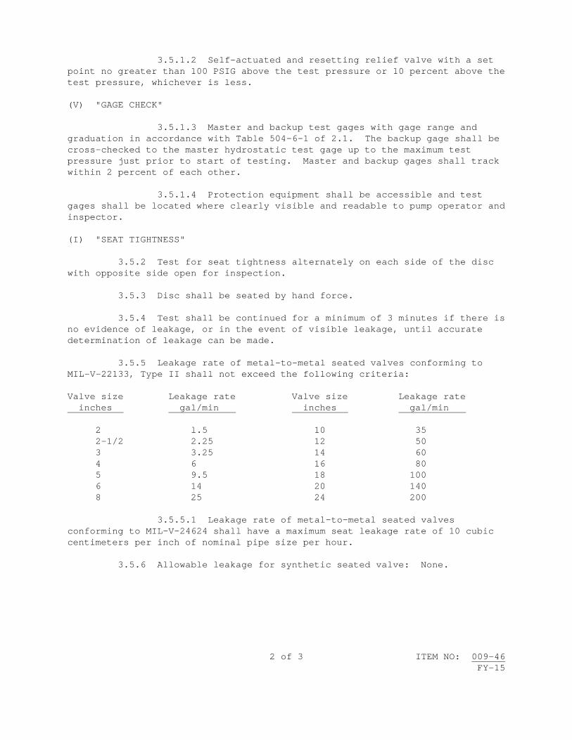
2 of 3 ITEM NO: 009-46 FY-15
3.5.1.2 Self-actuated and resetting relief valve with a set point no greater than 100 PSIG above the test pressure or 10 percent above the test pressure, whichever is less. (V) "GAGE CHECK" 3.5.1.3 Master and backup test gages with gage range and graduation in accordance with Table 504-6-1 of 2.1. The backup gage shall be cross-checked to the master hydrostatic test gage up to the maximum test pressure just prior to start of testing. Master and backup gages shall track within 2 percent of each other. 3.5.1.4 Protection equipment shall be accessible and test gages shall be located where clearly visible and readable to pump operator and inspector. (I) "SEAT TIGHTNESS" 3.5.2 Test for seat tightness alternately on each side of the disc with opposite side open for inspection. 3.5.3 Disc shall be seated by hand force. 3.5.4 Test shall be continued for a minimum of 3 minutes if there is no evidence of leakage, or in the event of visible leakage, until accurate determination of leakage can be made. 3.5.5 Leakage rate of metal-to-metal seated valves conforming to MIL-V-22133, Type II shall not exceed the following criteria: Valve size Leakage rate Valve size Leakage rate inches gal/min inches gal/min 2 l.5 10 35 2-1/2 2.25 12 50 3 3.25 14 60 4 6 16 80 5 9.5 18 100 6 14 20 140 8 25 24 200 3.5.5.1 Leakage rate of metal-to-metal seated valves conforming to MIL-V-24624 shall have a maximum seat leakage rate of 10 cubic centimeters per inch of nominal pipe size per hour. 3.5.6 Allowable leakage for synthetic seated valve: None.
3 of 3 ITEM NO: 009-46 FY-15
4. NOTES: 4.1 The test pressure of 3.5.2 will be specified in Work Item. 4.2 Repair of valve operating gear will be specified in Work Item. 4.3 Test medium will be specified in Work Item.


1 of 6 ITEM NO: 009-47 FY-15
NAVSEA STANDARD ITEM FY-15 ITEM NO: 009-47 DATE: 29 JUL 2011 CATEGORY: II 1. SCOPE: 1.1 Title: Gate Valve; repair 2. REFERENCES: 2.1 S9086-CJ-STM-010/CH-075, Fasteners 2.2 S9253-AD-MMM-010, Maintenance Manual for Valves, Traps, and Orifices
(Non-Nuclear), User's Guide and General Information 2.3 S9086-RJ-STM-010/CH-504, Pressure, Temperature and Other Mechanical
and Electromechanical Measuring Instruments 2.4 S9086-RK-STM-010/CH-505, Piping Systems 3. REQUIREMENTS: 3.1 Matchmark valve parts. (V) "INSPECT PARTS FOR DEFECTS" 3.2 Disassemble, clean internal and external surfaces free of foreign matter (including paint), and inspect parts for defects. 3.2.1 The removal of body-bound studs only to determine the condition of threads is not required. 3.2.1.1 Exposed portion of body-bound studs shall be inspected in accordance with Section 075-8.3 of 2.1. (I) or (V) “TORQUE TEST” (See 4.3) 3.2.2 Torque test each body-bound stud in accordance with Section 075-8.6.3.2(d) of 2.1. 3.3 Repair valve as follows: 3.3.1 Straighten stem to within 0.002-inch total indicator reading. Polish stem to a 32 Root-Mean-Square finish in way of packing surface and remove raised edges and foreign matter.

2 of 6 ITEM NO: 009-47 FY-15
3.3.2 Chase and tap exposed threaded areas. 3.3.3 Dress and true gasket mating surfaces. 3.3.4 Machine, grind, or lap and spot-in gate to seats (including backseat) to obtain a 360-degree continuous contact. (I) or (V) "INSPECT CONTACT" (See 4.4) 3.3.4.1 Inspect contact using blueing method. 3.3.4.2 Transfer line shall not exceed 3/16-inch in width and shall appear within the lower 75 percent of the gate seating surface. (I)(G) "VERIFY LEVEL I PARTS AND CLEANLINESS" 3.4 Assemble valve installing new gaskets in accordance with the manufacturer's specifications, using new fasteners for those removed in 3.2, in accordance with Attachment A, or for DDG-51 class, Attachment B. 3.4.1 Pack feedwater, condensate, and steam valves with valve stem packing conforming to MIL-P-24503/24583 combination in accordance with Chapter 6 of 2.2. 3.4.2 Pack valves of systems other than feedwater, condensate, or steam with valve stem packing conforming to MIL-P-24396, Type B. 3.5 Hydrostatically test valve as follows: 3.5.1 Hydrostatic test equipment shall have the following capabilities: 3.5.1.1 Manual overpressure protection release valve. 3.5.1.2 Self-actuated and resetting relief valve with a set point no greater than 100 PSIG above the test pressure or 10 percent above the test pressure, whichever is less. (V) "GAGE CHECK" 3.5.1.3 Master and backup test gages with gage range and graduation in accordance with Table 504-6-1 of 2.3. The backup gage shall be cross-checked to the master hydrostatic test gage up to the maximum test pressure just prior to start of testing. Master and backup gages shall track within 2 percent of each other. 3.5.1.4 Protection equipment shall be accessible and test gages shall be located where clearly visible and readable to pump operator and inspector.

3 of 6 ITEM NO: 009-47 FY-15
(V)(G) or (I)(G) "SEAT TIGHTNESS" (See 4.3) 3.5.2 Test for seat tightness alternately on each side of gate for double seated valves, and on outboard side only on single-seated valves, with the opposite side open for inspection. 3.5.2.1 Do not exceed the handwheel closing force specified in Table 505-11-2 of 2.4. 3.5.2.2 Test shall be continued for a minimum of 3 minutes if there is no evidence of leakage, or in the event of visible leakage, until accurate determination of leakage can be made. Maximum allowable leakage: 10 cubic centimeters (cc) per hour, per inch of nominal pipe size; 10 cc maximum per hour for valve sizes less than 1-1/2 inches. 4. NOTES: 4.1 The test pressures of 3.5.2 will be specified in Work Item. 4.2 Repair of valve operating gear will be specified in Work Item. 4.3 The paragraph referencing this note is considered an (I)(G) if the valve is Level I. If the valve is not Level I, the paragraph is considered a (V)(G). 4.4 The paragraph referencing this note is considered an (I) if the valve is Level I. If the valve is not Level I, the paragraph is considered a (V). 4.5 Test medium will be specified in Work Item.
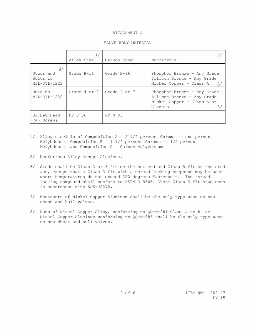
4 of 6 ITEM NO: 009-47 FY-15
ATTACHMENT A VALVE BODY MATERIAL
1/ Alloy Steel
Carbon Steel
2/ Nonferrous
3/ Studs and Bolts to MIL-DTL-1222
Grade B-16
Grade B-16
Phosphor Bronze - Any Grade Silicon Bronze - Any Grade Nickel Copper - Class A 4/
Nuts to MIL-DTL-1222
Grade 4 or 7 Grade 4 or 7 Phosphor Bronze - Any Grade Silicon Bronze - Any Grade Nickel Copper - Class A or Class B 5/
Socket Head Cap Screws
FF-S-86 FF-S-86
1/ Alloy steel is of Composition A - 2-1/4 percent Chromium, one percent
Molybdenum, Composition B - 1-1/4 percent Chromium, 1/2 percent Molybdenum, and Composition C - Carbon Molybdenum.
2/ Nonferrous Alloy except Aluminum. 3/ Studs shall be Class 2 or 3 fit on the nut end and Class 5 fit on the stud
and, except that a Class 3 fit with a thread locking compound may be used where temperatures do not exceed 250 degrees Fahrenheit. The thread locking compound shall conform to ASTM D 5363. Check Class 3 fit stud ends in accordance with SAE-J2270.
4/ Fasteners of Nickel Copper Aluminum shall be the only type used on sea
chest and hull valves. 5/ Nuts of Nickel Copper Alloy, conforming to QQ-N-281 Class A or B, or
Nickel Copper Aluminum conforming to QQ-N-286 shall be the only type used on sea chest and hull valves.

5 of 6 ITEM NO: 009-47 FY-15
ATTACHMENT B VALVE BODY MATERIAL
1/ Alloy Steel/Carbon Steel
2/ Nonferrous
3/ Studs and Bolts to MIL-DTL-1222
5/ For services up to and including 650 degrees Fahrenheit; Grade 5 steel
4/ 5/ Phosphor Bronze - Any Grade Silicon Bronze - Any Grade Nickel Copper - Class A
For services to 775 degrees Fahrenheit; Grade B-7 or B-16
For services to 1,000 degrees Fahrenheit; Grade B-16
For services in which JP-5 lubricating oil, or inflammable gas or liquid of any kind, regardless of pressure and temperature, which are within 3 feet of hot surfaces (above 650 degrees F) and where steel tubing is required; Grade 2, 5 or 8 steel
Bolting subject to seawater corrosion (other than hull integrity bolting; for hull integrity bolting see Note 4) Connections in contact with bilge regions. Where strength requires ferrous bolting and is exposed to the weather; Class A Nickel - Copper alloy to QQ-N-281 or silicon bronze to ASTM B 98 with dimensions of MIL-DTL-1222. Where greater strength is required, use Nickel - Copper - Aluminum alloy QQ-N-286.
Nuts to MIL-DTL-1222
5/ For services up to and including 650 degrees Fahrenheit; Grade 5 steel
Phosphor Bronze - Any Grade Silicon Bronze - Any Grade Nickel Copper - Class A or Class B 4/ 5/
For service to 775 degrees Fahrenheit; Grade 2H or 4 steel
For services to 1,000 degrees Fahrenheit; Grade 4 steel

6 of 6 ITEM NO: 009-47 FY-15
ATTACHMENT B (Con't)
1/ Alloy Steel/Carbon Steel
2/ Nonferrous
For services in which JP-5, lubricating oil, or inflammable gas or liquid of any kind, regardless of pressure and temperature which are within 3 feet of hot surfaces (above 650 degrees F) and where steel tubing is required; Grade 5 or 8 steel
Nuts subject to seawater corrosion. Connections in the bilge regions. Where strength requires ferrous material and is exposed to the weather; Class A or B Nickel Copper Alloy to QQ-N-281 or Silicon Bronze to ASTM B 98 with dimensions to MIL-DTL-1222
NOTES
1/ Alloy steel is of Composition A - 2-1/4 percent Chromium, one percent Molybdenum, Composition B - 1-1/4 percent Chromium, 1/2 percent Molybdenum, and Composition C - Carbon Molybdenum.
2/ Nonferrous Alloy except Aluminum.
3/ Studs shall be Class 2 or 3 fit on the nut end and Class 5 fit on the stud end, except that a Class 3 fit with a thread locking compound may be used where temperatures do not exceed 200 degrees Fahrenheit. The thread locking compound shall conform to ASTM D 5363. Check Class 3 fit stud ends in accordance with SAE-J2270.
4/ Fasteners of Nickel Copper Aluminum shall be the only type used on sea chest and hull valves.
5/ Where these materials would constitute part of a galvanic couple, proposals for alternate materials shall be submitted for approval.

1 of 5 ITEM NO: 009-48 FY-15
NAVSEA STANDARD ITEM FY-15 ITEM NO: 009-48 DATE: 29 JUL 2011 CATEGORY: II 1. SCOPE: 1.1 Title: Pressure Seal Bonnet Valve; repair (shop) 2. REFERENCES: 2.1 S9086-CJ-STM-010/CH-075, Fasteners 2.2. T9074-AS-GIB-010/271, Requirements for Nondestructive Testing Methods 2.3 MIL-STD-2035, Nondestructive Testing Acceptance Criteria 2.4 803-6074287, Repair Guide, Pressure Seal Valves 2.5 803-5001021, Pressure Seal Rings Standard and Oversize Valve Pressure
Class 600-1500 2.6 S9253-AD-MMM-010, Maintenance Manual for Valves, Traps, and Orifices
(Non-Nuclear), User's Guide and General Information 2.7 S9086-RJ-STM-010/CH-504, Pressure, Temperature and Other Mechanical
and Electromechanical Measuring Instruments 2.8 S9086-RK-STM-010/CH-505, Piping Systems 3. REQUIREMENTS: 3.1 Matchmark valve parts. (V) "INSPECT PARTS FOR DEFECTS" 3.2 Disassemble, clean internal and external surfaces free of foreign matter (including paint), and inspect parts for defects. 3.2.1 The removal of body-bound studs only to determine the condition of threads is not required. 3.2.1.1 Exposed portion of body-bound studs shall be inspected in accordance with Section 075-8.3 of 2.1.

2 of 5 ITEM NO: 009-48 FY-15
(I) or (V) “TORQUE TEST” (See 4.3) 3.2.2 Torque test each body-bound stud in accordance with Section 075-8.6.3.2(d) of 2.1. (I) "LIQUID PENETRANT INSPECT" 3.2.3 Accomplish liquid penetrant inspection of seats (including back seat), discs, or gate and body inlay area in accordance with 2.2. 3.2.3.1 Acceptance criteria shall be in accordance with Paragraph 7 of 2.3, except hairline cracks in hard-faced areas of seats and discs or gate are acceptable provided the valve does not show evidence of leakage. 3.3 Repair valve as follows: 3.3.1 Straighten stem to within 0.002-inch total indicator reading. Polish stem to a 32 Root-Mean-Square (RMS) finish in way of packing surface and remove raised edges and foreign matter. 3.3.2 Chase and tap exposed threaded areas. 3.3.3 Dress and true gasket mating surfaces. 3.3.4 Inspect and repair sealing surfaces of inlay area and bonnet as follows: (I) or (V) "VISUAL INSPECT" (See 4.3) 3.3.4.1 Inspect valve body to verify that stainless steel inlay is free of steam cuts and cracks and diameter of inlay area is round to within 0.003 inch and free of non-design taper. Measure diameter at top and bottom of inlay area in increments of 45 degrees, on each circle. 3.3.4.2 For the inlay, correct out-of-round, non-design tapered condition and provide 32 RMS finish. Finished inlay diameter shall provide 0.002 to 0.005 inch clearance on the standard size diameter for seal rings described by 2.4. 3.3.4.3 Machine valve bonnet tapered area for concentricity and design angle to within 0.002 inch total indicator reading and 32 RMS finish. 3.3.5 Machine, grind, or lap and spot-in discs or gate to seats (including back seat) to obtain a 360-degree continuous contact. (I) or (V) "INSPECT CONTACT" (See 4.3) 3.3.5.1 Inspect contact using blueing method.

3 of 5 ITEM NO: 009-48 FY-15
3.3.5.2 Transfer line for gate valve shall not exceed 3/16 inch in width and shall appear within the lower 75 percent of the gate seating surface. 3.3.5.3 Transfer line for globe valve shall not exceed 1/16 inch in width. (I)(G) "VERIFY LEVEL I PARTS AND CLEANLINESS" 3.4 Assemble valve, using new fasteners for those removed in 3.2, in accordance with Attachment A. 3.4.1 Install new seal ring in accordance with 2.4, using 2.5 for guidance. 3.4.1.1 The SUPERVISOR must approve fitting new seal ring to inlay bores above first oversize. 3.4.1.2 Attach a metal identification tag to the valve bonnet indicating the size of seal ring installed, straight or tapered body neck, name of installing activity, and date of installation. 3.4.2 Install new valve stem packing conforming to MIL-P-24503/24583 combination in accordance with Chapter 6 of 2.6. 3.5 Hydrostatically test valve as follows: 3.5.1 Hydrostatic test equipment shall have the following capabilities: 3.5.1.1 Manual overpressure protection release valve. 3.5.1.2 Self-actuated and resetting relief valve with a set point no greater than 100 PSIG above the test pressure or 10 percent above the test pressure, whichever is less. (V) "GAGE CHECK" 3.5.1.3 Master and backup test gages with gage range and graduation in accordance with Table 504-6-1 of 2.7. The backup gage shall be cross-checked to the master hydrostatic test gage up to the maximum test pressure just prior to start of testing. Master and backup gages shall track within 2 percent of each other. 3.5.1.4 Protection equipment shall be accessible and test gages shall be located where clearly visible and readable to pump operator and inspector.

4 of 5 ITEM NO: 009-48 FY-15
(V)(G) or (I)(G) "SEAT TIGHTNESS" (See 4.4) 3.5.2 Test for seat tightness alternately on each side of gate for double seated valves, and on outboard side only on single seated valves, with the opposite side open for inspection. 3.5.2.1 Do not exceed handwheel closing force specified in Table 505-11-2 of 2.8. 3.5.2.2 Test shall be continued for a minimum of 3 minutes if there is no evidence of leakage, or in the event of visible leakage, until accurate determination of leakage can be made. Maximum allowable leakage: 10 cubic centimeters (cc) per hour, per inch of nominal pipe size; 10 cc maximum per hour for valve sizes less than 1-1/2 inches. (V)(G) or (I)(G) "SEAT TIGHTNESS" (See 4.4) 3.5.3 Test globe valve in the direction tending to open valve. 3.5.3.1 Do not exceed the handwheel closing force specified in Table 505-11-2 of 2.8. 3.5.3.2 Test shall be continued for a minimum of 3 minutes if there is no evidence of leakage, or in the event of visible leakage, until accurate determination of leakage can be made. Maximum allowable leakage: 10 cubic centimeters (cc) per hour, per inch of nominal pipe size; 10 cc maximum per hour for valve sizes less than 1-1/2 inches. 4. NOTES: 4.1 The test pressures of 3.5.2 and 3.5.3 will be specified in Work Item. 4.2 Repair of valve operating gear will be specified in Work Item. 4.3 The paragraph referencing this note is considered an (I) if the valve is Level I. If the valve is not Level I, the paragraph is considered a (V). 4.4 The paragraph referencing this note is considered an (I)(G) if the valve is Level I. If the valve is not Level I, the paragraph is considered a (V)(G). 4.5 Reference 2.5 provides guidance with respect to applicable APLs and other information not in direct conflict with the material and hardness requirements for seal rings specified in 2.4. 4.6 Test medium will be specified in Work Item.

5 of 5 ITEM NO: 009-48 FY-15
ATTACHMENT A
VALVE BODY MATERIAL
1/ Alloy Steel
Carbon Steel
2/ Studs and Bolts to MIL-DTL-1222
Grade B-16
Grade B-16
Nuts to MIL-DTL-1222
Grade 4 or 7 Grade 4 or 7
Socket Head Cap Screws
FF-S-86 FF-S-86
1/ Alloy steel is of Composition A - 2-1/4 percent Chromium, one percent
Molybdenum, Composition B - 1-1/4 percent Chromium, 1/2 percent Molybdenum, and Composition C - Carbon Molybdenum.
2/ Studs shall be Class 2 or 3 fit on the nut end and Class 5 fit on the stud
end, except that a Class 3 fit with a thread locking compound may be used where temperatures do not exceed 250 degrees Fahrenheit. The thread locking compound shall conform to ASTM D 5363. Check Class 3 fit stud ends in accordance with SAE-J2270.


1 of 4 ITEM NO: 009-49 FY-15
NAVSEA STANDARD ITEM FY-15 ITEM NO: 009-49 DATE: 29 JUL 2011 CATEGORY: II 1. SCOPE: 1.1 Title: Pressure Seal Bonnet Valve; repair (in-line) 2. REFERENCES: 2.1 S9086-CJ-STM-010/CH-075, Fasteners 2.2 T9074-AS-GIB-010/271, Requirements for Nondestructive Testing Methods 2.3 MIL-STD-2035, Nondestructive Testing Acceptance Criteria 2.4 803-6074287, Repair Guide, Pressure Seal Valves 2.5 803-5001021, Pressure Seal Rings Standard and Oversize Valve Pressure
Class 600-1500 2.6 S9253-AD-MMM-010, Maintenance Manual for Valves, Traps, and Orifices
(Non-Nuclear), User's Guide and General Information 3. REQUIREMENTS: 3.1 Matchmark valve parts. (V) "INSPECT PARTS FOR DEFECTS" 3.2 Disassemble, clean free of foreign matter (including paint), and inspect parts for defects. 3.2.1 The removal of body-bound studs only to determine the condition of threads is not required. 3.2.1.1 Exposed portion of body-bound studs shall be inspected in accordance with Section 075-8.3 of 2.1. (I) or (V) “TORQUE TEST” (See 4.3) 3.2.2 Torque test each body-bound stud in accordance with Section 075-8.6.3.2(d) of 2.1.
2 of 4 ITEM NO: 009-49 FY-15
(I) "LIQUID PENETRANT INSPECT" 3.2.3 Accomplish liquid penetrant inspection of seats (including back seat), discs or gate, and body inlay area in accordance with 2.2. 3.2.3.1 Acceptance criteria shall be in accordance with Paragraph 7 of 2.3, except hairline cracks in hard-faced seats and discs or gate are acceptable provided the valve does not show evidence of leakage. 3.3 Repair valve as follows: 3.3.1 Straighten stem to within 0.002-inch total indicator reading. Polish stem to a 32 Root-Mean-Square (RMS) finish in way of packing surface and remove raised edges and foreign matter. 3.3.2 Chase and tap exposed threaded areas. 3.3.3 Inspect and repair sealing surfaces of inlay area and bonnet as follows: (I) or (V) "VISUAL INSPECT" (See 4.3) 3.3.3.1 Inspect valve body to verify that stainless steel inlay is free of steam cuts and cracks and that diameter of inlay area is round to within 0.003 inch and free of non-design taper. Measure diameter at top and bottom of inlay area in increments of 45 degrees, on each circle. 3.3.3.2 For the inlay, correct out-of-round, non-design tapered condition and provide 32 RMS finish. Finished inlay diameter shall not exceed oversize number one diameter, plus 0.002 to 0.005-inch clearance described by 2.4. 3.3.3.3 Machine valve bonnet tapered area for concentricity and design angle to within 0.002-inch total indicator reading and 32 RMS finish. 3.3.4 Machine, grind, or lap and spot-in discs or gate to seats (including back seat) to obtain a 360-degree continuous contact. (I) or (V) "INSPECT CONTACT" (See 4.3) 3.3.4.1 Inspect contact using blueing method. 3.3.4.2 Transfer line for gate valve shall not exceed 3/16-inch in width and shall appear within the lower 75 percent of the gate seating surface. 3.3.4.3 Transfer line for globe valve shall not exceed 1/16-inch in width.

3 of 4 ITEM NO: 009-49 FY-15
(I)(G) "VERIFY LEVEL I PARTS AND CLEANLINESS" 3.4 Assemble valve, using new fasteners for those removed in 3.2, in accordance with Attachment A. 3.4.1 Install new seal ring in accordance with 2.4, using 2.5 for guidance. 3.4.1.1 The SUPERVISOR must approve new seal rings to inlay bores above first oversize. 3.4.1.2 Attach a metal identification tag to the valve bonnet indicating the size of seal ring installed, straight or tapered body neck, name of installing activity, and date of installation. 3.4.2 Install new valve stem packing conforming to MIL-P-24503/24583 combination in accordance with Chapter 6 of 2.6. 4. NOTES: 4.1 Operational test of the valve will be specified in Work Item. 4.2 Repair of valve operating gear will be specified in Work Item. 4.3 The paragraph referencing this note is considered an (I) if the valve is Level I. If the valve is not Level I, the paragraph is considered a (V).

4 of 4 ITEM NO: 009-49 FY-15
ATTACHMENT A
VALVE BODY MATERIAL
1/ Alloy Steel
Carbon Steel
2/ Studs and Bolts to MIL-DTL-1222
Grade B-16
Grade B-16
Nuts to MIL-DTL-1222
Grade 4 or 7 Grade 4 or 7
Socket Head Cap Screws
FF-S-86 FF-S-86
1/ Alloy steel is of Composition A - 2-1/4 percent Chromium, one percent
Molybdenum, Composition B - 1-1/4 percent Chromium, 1/2 percent Molybdenum, and Composition C - Carbon Molybdenum.
2/ Studs shall be Class 2 or 3 fit on the nut end and Class 5 fit on the stud
end, except that a Class 3 fit with a thread locking compound may be used where temperatures do not exceed 250 degrees Fahrenheit. The thread locking compound shall conform to ASTM D 5363. Check Class 3 fit stud ends in accordance with SAE-J2270.

1 of 5 ITEM NO: 009-50 FY-15
NAVSEA STANDARD ITEM FY-15 ITEM NO: 009-50 DATE: 29 JUL 2011 CATEGORY: II 1. SCOPE: 1.1 Title: Horizontal Swing Check Valve; repair 2. REFERENCES: 2.1 S9086-RJ-STM-010/CH-504, Pressure, Temperature and Other Mechanical and Electromechanical Measuring Instruments 3. REQUIREMENTS: 3.1 Matchmark valve parts. (V) "INSPECT PARTS FOR DEFECTS" 3.2 Disassemble, clean internal and external surfaces free of foreign matter (including paint), and inspect parts for defects. 3.3 Repair valve as follows: 3.3.1 Chase and tap exposed threaded areas. 3.3.2 Dress and true gasket mating surfaces. 3.3.3 Machine, grind, or lap and spot-in disc to seat to obtain 360-degree continuous contact. (V) "INSPECT CONTACT" 3.3.3.1 Inspect contact using blueing method. 3.3.3.2 Transfer line for swing check valve shall not exceed 1/16-inch in width. 3.4 Assemble valve installing new gaskets, bushings, disc retaining nut, hinge pin, and plug in accordance with the manufacturer's specifications, and new fasteners in accordance with Attachment A, or for DDG-51 class, Attachment B. 3.5 Hydrostatically test valve as follows:

2 of 5 ITEM NO: 009-50 FY-15
3.5.1 Hydrostatic test equipment shall have the following capabilities: 3.5.1.1 Manual overpressure protection release valve. 3.5.1.2 Self-actuated and resetting relief valve with a set point no greater than 100 PSIG above the test pressure or 10 percent above the test pressure, whichever is less. (V) "GAGE CHECK" 3.5.1.3 Master and backup test gages with gage range and graduation in accordance with Table 504-6-1 of 2.1. The backup gage shall be cross-checked to the master hydrostatic test gage up to the maximum test pressure just prior to start of testing. Master and backup gages shall track within 2 percent of each other. 3.5.1.4 Protection equipment shall be accessible and test gages shall be located where clearly visible and readable to pump operator and inspector. (I) "SEAT TIGHTNESS" 3.5.2 Test for seat tightness in the direction tending to close the valve (back pressure) for a minimum of 5 minutes. Allowable leakage as follows: VALVE SIZE (NOM) LEAKAGE RATE Up to 2 inches inclusive 25 cc/hr./in. dia. 2-1/2 inches - 10 inches inclusive 50 cc/hr./in. dia. Over 10 inches 100 cc/hr./in. dia. The back pressure applied shall be in accordance with the following: VALVE PRESSURE RATING TEST BACK PRESSURE 150 PSIG and Below 50 PSIG Over 150 PSIG 100 PSIG 4. NOTES: 4.1 Test medium will be specified in Work Item.

3 of 5 ITEM NO: 009-50 FY-15
ATTACHMENT A VALVE BODY MATERIAL
1/ Alloy Steel
Carbon Steel
2/ Nonferrous
3/ Studs and Bolts to MIL-DTL-1222
Grade B-16
Grade B-16
Phosphor Bronze - Any Grade Silicon Bronze - Any Grade Nickel Copper - Class A 4/
Nuts to MIL-DTL-1222
Grade 4 or 7 Grade 4 or 7 Phosphor Bronze - Any Grade Silicon Bronze - Any Grade Nickel Copper - Class A or Class B 5/
Socket Head Cap Screws
FF-S-86 FF-S-86
1/ Alloy steel is of Composition A - 2-1/4 percent Chromium, one percent
Molybdenum, Composition B - 1-1/4 percent Chromium, 1/2 percent Molybdenum, and Composition C - Carbon Molybdenum.
2/ Nonferrous Alloy except Aluminum. 3/ Studs shall be Class 2 or 3 fit on the nut end and Class 5 fit on the stud
and, except that a Class 3 fit with a thread locking compound may be used where temperatures do not exceed 250 degrees Fahrenheit. The thread locking compound shall conform to ASTM D 5363. Check Class 3 fit stud ends in accordance with SAE-J2270.
4/ Fasteners of Nickel Copper Aluminum shall be the only type used on sea
chest and hull valves. 5/ Nuts of Nickel Copper Alloy, conforming to QQ-N-281 Class A or B, or
Nickel Copper Aluminum conforming to QQ-N-286 shall be the only type used on sea chest and hull valves.

4 of 5 ITEM NO: 009-50 FY-15
ATTACHMENT B VALVE BODY MATERIAL
1/ Alloy Steel/Carbon Steel
2/ Nonferrous
3/ Studs and Bolts to MIL-DTL-1222
5/ For services up to and including 650 degrees Fahrenheit; Grade 5 steel
4/ 5/ Phosphor Bronze - Any Grade Silicon Bronze - Any Grade Nickel Copper - Class A
For services to 775 degrees Fahrenheit; Grade B-7 or B-16
For services to 1,000 degrees Fahrenheit; Grade B-16
For services in which JP-5 lubricating oil, or inflammable gas or liquid of any kind, regardless of pressure and temperature, which are within 3 feet of hot surfaces (above 650 degrees F) and where steel tubing is required; Grade 2, 5 or 8 steel
Bolting subject to seawater corrosion (other than hull integrity bolting; for hull integrity bolting see Note 4) Connections in contact with bilge regions. Where strength requires ferrous bolting and is exposed to the weather; Class A Nickel - Copper alloy to QQ-N-281 or silicon bronze to ASTM B 98 with dimensions of MIL-DTL-1222. Where greater strength is required, use Nickel - Copper - Aluminum alloy QQ-N-286.
Nuts to MIL-DTL-1222
5/ For services up to and including 650 degrees Fahrenheit; Grade 5 steel
Phosphor Bronze - Any Grade Silicon Bronze - Any Grade Nickel Copper - Class A or Class B 4/ 5/
For service to 775 degrees Fahrenheit; Grade 2H or 4 steel
For services to 1,000 degrees Fahrenheit; Grade 4 steel

5 of 5 ITEM NO: 009-50 FY-15
ATTACHMENT B (Con't)
1/ Alloy Steel/Carbon Steel
2/ Nonferrous
For services in which JP-5, lubricating oil, or inflammable gas or liquid of any kind, regardless of pressure and temperature which are within 3 feet of hot surfaces (above 650 degrees F) and where steel tubing is required; Grade 5 or 8 steel
Nuts subject to seawater corrosion. Connections in the bilge regions. Where strength requires ferrous material and is exposed to the weather; Class A or B Nickel Copper Alloy to QQ-N-281 or Silicon Bronze to ASTM B 98 with dimensions to MIL-DTL-1222
NOTES 1/ Alloy steel is of Composition A - 2-1/4 percent Chromium, one percent
Molybdenum, Composition B - 1-1/4 percent Chromium, 1/2 percent Molybdenum, and Composition C - Carbon Molybdenum.
2/ Nonferrous Alloy except Aluminum. 3/ Studs shall be Class 2 or 3 fit on the nut end and Class 5 fit on the stud
end, except that a Class 3 fit with a thread locking compound may be used where temperatures do not exceed 200 degrees Fahrenheit. The thread locking compound shall conform to ASTM D 5363. Check Class 3 fit stud ends in accordance with SAE-J2270.
4/ Fasteners of Nickel Copper Aluminum shall be the only type used on sea
chest and hull valves. 5/ Where these materials would constitute part of a galvanic couple,
proposals for alternate materials shall be submitted for approval.


1 of 6 ITEM NO: 009-51 FY-15
NAVSEA STANDARD ITEM
FY-15 ITEM NO: 009-51 DATE: 17 JAN 2013 CATEGORY: II 1. SCOPE: 1.1 Title: Globe, Globe Angle, and Globe Stop Check Valve; repair 2. REFERENCES: 2.1 S9086-CJ-STM-010/CH-075, Fasteners 2.2 S9253-AD-MMM-010, Maintenance Manual for Valves, Traps, and Orifices
(Non-Nuclear), User's Guide and General Information 2.3 S9086-RJ-STM-010/CH-504, Pressure, Temperature and Other Mechanical
and Electromechanical Measuring Instruments 2.4 S9086-RK-STM-010/CH-505, Piping Systems 3. REQUIREMENTS: 3.1 Matchmark valve parts. (V) "INSPECT PARTS FOR DEFECTS" 3.2 Disassemble, clean internal and external surfaces free of foreign matter (including paint), and inspect parts for defects. 3.2.1 The removal of body-bound studs only to determine the condition of threads is not required. 3.2.1.1 Exposed portion of body-bound studs shall be inspected in accordance with Section 075-8.3 of 2.1. (I) or (V) “TORQUE TEST” (See 4.3) 3.2.2 Torque test each body-bound stud in accordance with Section 075-8.6.3.2(d) of 2.1. 3.3 Repair valve as follows: 3.3.1 Straighten stem to within 0.002-inch total indicator reading. Polish stem to a 32 Root-Mean-Square finish in way of packing surface and remove raised edges and foreign matter.

2 of 6 ITEM NO: 009-51 FY-15
3.3.2 Chase and tap exposed threaded areas. 3.3.3 Dress and true gasket mating surfaces. 3.3.4 Machine, grind, or lap and spot-in disc to seat to obtain a 360-degree continuous contact. (I) or (V) "INSPECT CONTACT" (See 4.3) 3.3.4.1 Inspect contact using blueing method (soft seated valves excluded). 3.3.4.2 Transfer line (hard seated valves) shall not exceed 1/16-inch in width. (I)(G) "VERIFY LEVEL I PARTS AND CLEANLINESS" 3.4 Assemble valve installing new gaskets in accordance with manufacturer's specifications, installing new fasteners for those removed in 3.2, in accordance with Attachment A, or for DDG-51 class, Attachment B. 3.4.1 Pack feedwater, condensate, and steam valves with valve stem packing conforming to MIL-P-24503/24583 combination in accordance with Chapter 6 of 2.2. 3.4.2 Pack valves of systems other than feedwater, condensate, or steam with valve packing conforming to MIL-P-24396, Type B. 3.5 Hydrostatically test valve as follows: 3.5.1 Hydrostatic test equipment shall have the following capabilities: 3.5.1.1 Manual overpressure protection release valve. 3.5.1.2 Self-actuated and resetting relief valve with a set point no greater than 100 PSIG above the test pressure or 10 percent above the test pressure, whichever is less. (V) "GAGE CHECK" 3.5.1.3 Master and backup test gages with gage range and graduation in accordance with Table 504-6-1 of 2.3. The backup gage shall be cross-checked to the master hydrostatic test gage up to the maximum test pressure just prior to start of testing. Master and backup gages shall track within 2 percent of each other. 3.5.1.4 Protection equipment shall be accessible and test gages shall be located where clearly visible and readable to pump operator and inspector.

3 of 6 ITEM NO: 009-51 FY-15
(V)(G) or (I)(G) "SEAT TIGHTNESS" (See 4.4) 3.5.2 Test for seat tightness in the direction tending to open valve. 3.5.2.1 Do not exceed the handwheel closing force specified in Table 505-11-2 of 2.4. 3.5.2.2 Test shall be continued for a minimum of 3 minutes if there is no evidence of leakage, or in the event of visible leakage, until accurate determination of leakage can be made. Maximum allowable leakage: 10 cubic centimeters (cc) per hour, per inch of nominal pipe size; 10 cc maximum per hour for valve sizes less than 1-1/2 inches. (V)(G) or (I)(G) "SEAT TIGHTNESS" (See 4.4) 3.5.3 Back pressure test globe stop check valve with stem in the open position. Allowable leakage as follows: VALVE SIZE (NOM) LEAKAGE RATE Up to 2 inches inclusive 25 cc/hr./in. dia. 2-1/2 inches - 10 inches inclusive 50 cc/hr./in. dia. Over 10 inches 100 cc/hr./in. dia. The back pressure applied shall be in accordance with the following: VALVE PRESSURE RATING TEST BACK PRESSURE 150 PSIG and below 50 PSIG Over 150 PSIG 100 PSIG 4. NOTES: 4.1 The test pressures of 3.5.2 will be specified in Work Item. 4.2 Repair of valve operating gear will be specified in Work Item. 4.3 The paragraph referencing this note is considered an (I) if the valve is Level I. If the valve is not Level I, the paragraph is considered a (V). 4.4 The paragraph referencing this note is considered an (I)(G) if the valve is Level I. If the valve is not Level I, the paragraph is considered a (V)(G).
4.5 Test medium will be specified in Work Item.

4 of 6 ITEM NO: 009-51 FY-15
ATTACHMENT A
VALVE BODY MATERIAL
1/ Alloy Steel
Carbon Steel
2/ Nonferrous
3/ Studs and Bolts to MIL-DTL-1222
Grade B-16
Grade B-16
Phosphor Bronze - Any Grade Silicon Bronze - Any Grade Nickel Copper - Class A 4/
Nuts to MIL-DTL-1222
Grade 4 or 7 Grade 4 or 7 Phosphor Bronze - Any Grade Silicon Bronze - Any Grade Nickel Copper - Class A or Class B 5/
Socket Head Cap Screws
FF-S-86 FF-S-86
1/ Alloy steel is of Composition A - 2-1/4 percent Chromium, one percent
Molybdenum, Composition B - 1-1/4 percent Chromium, 1/2 percent Molybdenum, and Composition C - Carbon Molybdenum.
2/ Nonferrous Alloy except Aluminum. 3/ Studs shall be Class 2 or 3 fit on the nut end and Class 5 fit on the stud
and, except that a Class 3 fit with a thread locking compound may be used where temperatures do not exceed 250 degrees Fahrenheit. The thread locking compound shall conform to ASTM D 5363. Check Class 3 fit stud ends in accordance with SAE-J2270.
4/ Fasteners of Nickel Copper Aluminum shall be the only type used on sea
chest and hull valves. 5/ Nuts of Nickel Copper Alloy, conforming to QQ-N-281 Class A or B, or
Nickel Copper Aluminum conforming to QQ-N-286 shall be the only type used on sea chest and hull valves.

5 of 6 ITEM NO: 009-51 FY-15
ATTACHMENT B
VALVE BODY MATERIAL
1/ Alloy Steel/Carbon Steel
2/ Nonferrous
3/ Studs and Bolts to MIL-DTL-1222
5/ For services up to and including 650 degrees Fahrenheit; Grade 5 steel
4/ 5/ Phosphor Bronze - Any Grade Silicon Bronze - Any Grade Nickel Copper - Class A
For services to 775 degrees Fahrenheit; Grade B-7 or B-16
For services to 1,000 degrees Fahrenheit; Grade B-16
For services in which JP-5 lubricating oil, or inflammable gas or liquid of any kind, regardless of pressure and temperature, which are within 3 feet of hot surfaces (above 650 degrees F) and where steel tubing is required; Grade 2, 5 or 8 steel
Bolting subject to seawater corrosion (other than hull integrity bolting; for hull integrity bolting see Note 4) Connections in contact with bilge regions. Where strength requires ferrous bolting and is exposed to the weather; Class A Nickel - Copper alloy to QQ-N-281 or silicon bronze to ASTM B 98 with dimensions of MIL-DTL-1222. Where greater strength is required, use Nickel - Copper - Aluminum alloy QQ-N-286.
Nuts to MIL-DTL-1222
5/ For services up to and including 650 degrees Fahrenheit; Grade 5 steel
Phosphor Bronze - Any Grade Silicon Bronze - Any Grade Nickel Copper - Class A or Class B 4/ 5/
For service to 775 degrees Fahrenheit; Grade 2H or 4 steel
For services to 1,000 degrees Fahrenheit; Grade 4 steel

6 of 6 ITEM NO: 009-51 FY-14
ATTACHMENT B (Con't)
1/ Alloy Steel/Carbon Steel
2/ Nonferrous
For services in which JP-5, lubricating oil, or inflammable gas or liquid of any kind, regardless of pressure and temperature which are within 3 feet of hot surfaces (above 650 degrees F) and where steel tubing is required; Grade 5 or 8 steel
Nuts subject to seawater corrosion. Connections in the bilge regions. Where strength requires ferrous material and is exposed to the weather; Class A or B Nickel Copper Alloy to QQ-N-281 or Silicon Bronze to ASTM B 98 with dimensions to MIL-DTL-1222
NOTES 1/ Alloy steel is of Composition A - 2-1/4 percent Chromium, one percent
Molybdenum, Composition B - 1-1/4 percent Chromium, 1/2 percent Molybdenum, and Composition C - Carbon Molybdenum.
2/ Nonferrous Alloy except Aluminum.
3/ Studs shall be Class 2 or 3 fit on the nut end and Class 5 fit on the stud end, except that a Class 3 fit with a thread locking compound may be used where temperatures do not exceed 200 degrees Fahrenheit. The thread locking compound shall conform to ASTM D 5363. Check Class 3 fit stud ends in accordance with SAE-J2270.
4/ Fasteners of Nickel Copper Aluminum shall be the only type used on sea chest and hull valves.
5/ Where these materials would constitute part of a galvanic couple, proposals for alternate materials shall be submitted for approval.

1 of 5 ITEM NO: 009-52 FY-15
NAVSEA STANDARD ITEM FY-15 ITEM NO: 009-52 DATE: 29 JUL 2011 CATEGORY: II 1. SCOPE: 1.1 Title: Relief Valve; repair 2. REFERENCES: 2.1 S9086-RJ-STM-010/CH-504, Pressure, Temperature and Other Mechanical
and Electromechanical Measuring Instruments 3. REQUIREMENTS: 3.1 Matchmark valve parts. (V) "INSPECT PARTS FOR DEFECTS" 3.2 Disassemble, clean internal and external surfaces free of foreign matter (including paint), and inspect parts for defects. 3.3 Repair valve as follows: 3.3.1 Straighten stem to within 0.002-inch total indicator reading. Polish stem to a 32 Root-Mean-Square finish and remove raised edges and foreign matter. 3.3.2 Machine, grind, or lap and spot-in metallic disc to seat to obtain a 360-degree continuous contact. (V) "INSPECT CONTACT" 3.3.2.1 Inspect contact using blueing method. Transfer line shall not exceed 1/16-inch in width. 3.3.3 Dress and true gasket mating surfaces. 3.3.4 Chase and tap exposed threaded areas. 3.4 Assemble valve installing new packing, soft seats, and gaskets in accordance with manufacturer's specifications and new fasteners in accordance with Attachment A, or for DDG-51 class, Attachment B.

2 of 5 ITEM NO: 009-52 FY-15
3.5 Hydrostatically test valve as follows: 3.5.1 Hydrostatic test equipment shall have the following capabilities: 3.5.1.1 Manual overpressure protection release valve. 3.5.1.2 Self-actuated and resetting relief valve with a set point no greater than 100 PSIG above the test pressure or 10 percent above the test pressure, whichever is less. (V) "GAGE CHECK" 3.5.1.3 Master and backup test gages with gage range and graduation in accordance with Table 504-6-1 of 2.1. The backup gage shall be cross-checked to the master hydrostatic test gage up to the maximum test pressure just prior to start of testing. Master and backup gages shall track within 2 percent of each other. 3.5.1.4 Protection equipment shall be accessible and test gages shall be located where clearly visible and readable to pump operator and inspector. (I) "SHOP TEST" 3.6 Shop test and set valve to lifting pressure. 3.6.1 Seat tightness test shall be accomplished for a minimum of 3 minutes. Allowable leakage: None. 3.6.2 Purge valve of test medium. 3.6.3 Install wire and lead lock seals. 3.7 Attach a metal tag to valve, stamped with the following information: 3.7.1 Ship name and hull number 3.7.2 Valve number or identification 3.7.3 Valve lifting pressure 3.7.4 Date valve tested and set 3.7.5 Name of repair facility 4. NOTES: 4.1 Test medium, seat tightness, and lifting pressures will be specified in Work Item.

3 of 5 ITEM NO: 009-52 FY-15
ATTACHMENT A VALVE BODY MATERIAL
1/ Alloy Steel
Carbon Steel
2/ Nonferrous
3/ Studs and Bolts to MIL-DTL-1222
Grade B-16
Grade B-16
Phosphor Bronze - Any Grade Silicon Bronze - Any Grade Nickel Copper - Class A 4/
Nuts to MIL-DTL-1222
Grade 4 or 7 Grade 4 or 7 Phosphor Bronze - Any Grade Silicon Bronze - Any Grade Nickel Copper - Class A or Class B 5/
Socket Head Cap Screws
FF-S-86 FF-S-86
1/ Alloy steel is of Composition A - 2-1/4 percent Chromium, one percent
Molybdenum, Composition B - 1-1/4 percent Chromium, 1/2 percent Molybdenum, and Composition C - Carbon Molybdenum.
2/ Nonferrous Alloy except Aluminum. 3/ Studs shall be Class 2 or 3 fit on the nut end and Class 5 fit on the stud
and, except that a Class 3 fit with a thread locking compound may be used where temperatures do not exceed 250 degrees Fahrenheit. The thread locking compound shall conform to ASTM D 5363. Check Class 3 fit stud ends in accordance with SAE-J2270.
4/ Fasteners of Nickel Copper Aluminum shall be the only type used on sea
chest and hull valves. 5/ Nuts of Nickel Copper Alloy, conforming to QQ-N-281 Class A or B, or
Nickel Copper Aluminum conforming to QQ-N-286 shall be the only type used on sea chest and hull valves.

4 of 5 ITEM NO: 009-52 FY-15
ATTACHMENT B VALVE BODY MATERIAL
1/ Alloy Steel/Carbon Steel
2/ Nonferrous
3/ Studs and Bolts to MIL-DTL-1222
5/ For services up to and including 650 degrees Fahrenheit; Grade 5 steel
4/ 5/ Phosphor Bronze - Any Grade Silicon Bronze - Any Grade Nickel Copper - Class A
For services to 775 degrees Fahrenheit; Grade B-7 or B-16
For services to 1,000 degrees Fahrenheit; Grade B-16
For services in which JP-5 lubricating oil, or inflammable gas or liquid of any kind, regardless of pressure and temperature, which are within 3 feet of hot surfaces (above 650 degrees F) and where steel tubing is required; Grade 2, 5 or 8 steel
Bolting subject to seawater corrosion (other than hull integrity bolting; for hull integrity bolting see Note 4) Connections in contact with bilge regions. Where strength requires ferrous bolting and is exposed to the weather; Class A Nickel - Copper alloy to QQ-N-281 or silicon bronze to ASTM B 98 with dimensions of MIL-DTL-1222. Where greater strength is required, use Nickel - Copper - Aluminum alloy QQ-N-286.
Nuts to MIL-DTL-1222
5/ For services up to and including 650 degrees Fahrenheit; Grade 5 steel
Phosphor Bronze - Any Grade Silicon Bronze - Any Grade Nickel Copper - Class A or Class B 4/ 5/
For service to 775 degrees Fahrenheit; Grade 2H or 4 steel
For services to 1,000 degrees Fahrenheit; Grade 4 steel

5 of 5 ITEM NO: 009-52 FY-15
ATTACHMENT B (Con't)
1/ Alloy Steel/Carbon Steel
2/ Nonferrous
For services in which JP-5, lubricating oil, or inflammable gas or liquid of any kind, regardless of pressure and temperature which are within 3 feet of hot surfaces (above 650 degrees F) and where steel tubing is required; Grade 5 or 8 steel
Nuts subject to seawater corrosion. Connections in the bilge regions. Where strength requires ferrous material and is exposed to the weather; Class A or B Nickel Copper Alloy to QQ-N-281 or Silicon Bronze to ASTM B 98 with dimensions to MIL-DTL-1222
NOTES 1/ Alloy steel is of Composition A - 2-1/4 percent Chromium, one percent
Molybdenum, Composition B - 1-1/4 percent Chromium, 1/2 percent Molybdenum, and Composition C - Carbon Molybdenum.
2/ Nonferrous Alloy except Aluminum. 3/ Studs shall be Class 2 or 3 fit on the nut end and Class 5 fit on the stud
end, except that a Class 3 fit with a thread locking compound may be used where temperatures do not exceed 200 degrees Fahrenheit. The thread locking compound shall conform to ASTM D 5363. Check Class 3 fit stud ends in accordance with SAE-J2270.
4/ Fasteners of Nickel Copper Aluminum shall be the only type used on sea
chest and hull valves. 5/ Where these materials would constitute part of a galvanic couple,
proposals for alternate materials shall be submitted for approval.


1 of 5 ITEM NO: 009-53 FY-15
NAVSEA STANDARD ITEM FY-15 ITEM NO: 009-53 DATE: 29 JUL 2011 CATEGORY: II 1. SCOPE: 1.1 Title: Bolted Bonnet Steam Valve; repair (shop) 2. REFERENCES: 2.1 S9086-CJ-STM-010/CH-075, Fasteners 2.2 T9074-AS-GIB-010/271, Requirements for Nondestructive Testing Methods 2.3 MIL-STD-2035, Nondestructive Testing Acceptance Criteria 2.4 S9253-AD-MMM-010, Maintenance Manual for Valves, Traps, and Orifices
(Non-Nuclear), User's Guide and General Information 2.5 S9086-RJ-STM-010/CH-504, Pressure, Temperature and Other Mechanical
and Electromechanical Measuring Instruments 2.6 S9086-RK-STM-010/CH-505, Piping Systems 3. REQUIREMENTS: 3.1 Matchmark valve parts. (V) "INSPECT PARTS FOR DEFECTS" 3.2 Disassemble, clean internal and external surfaces free of foreign matter (including paint), and inspect parts for defects. 3.2.1 The removal of body-bound studs only to determine the condition of threads is not required. 3.2.1.1 Exposed portion of body-bound studs shall be inspected in accordance with Section 075-8.3 of 2.1. (I) or (V) “TORQUE TEST” (See 4.3) 3.2.2 Torque test each body-bound stud in accordance with Section 075-8.6.3.2(d) of 2.1.

2 of 5 ITEM NO: 009-53 FY-15
(I) "LIQUID PENETRANT INSPECT" 3.2.3 Accomplish liquid penetrant inspection of seats (including back seat), discs, or gate in accordance with 2.2. 3.2.3.1 Acceptance criteria shall be in accordance with Paragraph 7 of 2.3, except hairline cracks in hard-faced areas of seats and discs or gate are acceptable provided the valve does not show evidence of leakage. 3.3 Repair valve as follows: 3.3.1 Straighten stem to within 0.002-inch total indicator reading. Polish stem to a 32 Root-Mean-Square finish in way of packing surface and remove raised edges and foreign matter. 3.3.2 Chase and tap exposed threaded areas. 3.3.3 Dress and true gasket mating surfaces. 3.3.4 Machine, grind, or lap and spot-in gate or discs to seats (including back seat) to obtain a 360-degree continuous contact. (I) or (V) "INSPECT CONTACT" (See 4.3) 3.3.4.1 Inspect contact using blueing method. 3.3.4.2 Transfer line for gate valve shall not exceed 3/16 inch in width and shall appear within the lower 75 percent of the gate seating surface. 3.3.4.3 Transfer line for globe valve shall not exceed 1/16 inch in width. (I)(G) "VERIFY LEVEL I PARTS AND CLEANLINESS" 3.4 Assemble valve, installing new gaskets in accordance with the manufacturer's specifications, installing new fasteners for those removed in 3.2, in accordance with Attachment A. 3.4.1 Install new valve stem packing conforming to MIL-P-24503/24583 combination in accordance with Chapter 6 of 2.4. 3.5 Hydrostatically test valve as follows: 3.5.1 Hydrostatic test equipment shall have the following capabilities: 3.5.1.1 Manual overpressure protection release valve.

3 of 5 ITEM NO: 009-53 FY-15
3.5.1.2 Self-actuated and resetting relief valve with a set point no greater than 100 PSIG above the test pressure or 10 percent above the test pressure, whichever is less. (V) "GAGE CHECK" 3.5.1.3 Master and backup test gages with gage range and graduation in accordance with Table 504-6-1 of 2.5. The backup gage shall be cross-checked to the master hydrostatic test gage up to the maximum test pressure just prior to start of testing. Master and backup gages shall track within 2 percent of each other. 3.5.1.4 Protection equipment shall be accessible and test gages shall be located where clearly visible and readable to pump operator and inspector. (V)(G) or (I)(G) "SEAT TIGHTNESS" (See 4.4) 3.5.2 Test for seat tightness alternately on each side of gate for double seated valves, and on outboard side only on single seated valves, with the opposite side open for inspection. 3.5.2.1 Do not exceed handwheel closing force specified in Table 505-11-2 of 2.6. 3.5.2.2 Test shall be continued for a minimum of 3 minutes if there is no evidence of leakage, or in the event of visible leakage, until accurate determination of leakage can be made. Maximum allowable leakage: 10 cubic centimeters (cc) per hour, per inch of nominal pipe size; 10 cc maximum per hour for valve sizes less than 1-1/2 inches. (V)(G) or (I)(G) "SEAT TIGHTNESS" (See 4.4) 3.5.3 Test globe valve in the direction tending to open valve. 3.5.3.1 Do not exceed the handwheel closing force specified in Table 505-11-2 of 2.6. 3.5.3.2 Test shall be continued for a minimum of 3 minutes if there is no evidence of leakage, or in the event of visible leakage, until accurate determination of leakage can be made. Maximum allowable leakage: 10 cubic centimeters (cc) per hour, per inch of nominal pipe size; 10 cc maximum per hour for valve sizes less than 1-1/2 inches. (V)(G) or (I)(G) "BACK PRESSURE TEST" (See 4.4) 3.5.4 Back pressure test globe stop check valve with stem in the open position. Allowable leakage as follows:

4 of 5 ITEM NO: 009-53 FY-15
VALVE SIZE (NOM) LEAKAGE RATE Up to 2 inches inclusive 25 cc/hr./in.dia. 2-1/2 inches - 10 inches inclusive 50 cc/hr./in.dia. Over 10 inches 100 cc/hr./in.dia. The back pressure applied shall be in accordance with the following: VALVE PRESSURE RATING TEST BACK PRESSURE 100 PSIG and Below 50 PSIG Over 150 PSIG 100 PSIG 4. NOTES: 4.1 The test pressures of 3.5.2 and 3.5.3 will be specified in Work Item. 4.2 Repair of valve operating gear will be specified in Work Item. 4.3 The paragraph referencing this note is considered an (I) if the valve is Level I. If the valve is not Level I, the paragraph is considered a (V). 4.4 The paragraph referencing this note is considered an (I)(G) if the valve is Level I. If the valve is not Level I, the paragraph is considered a (V)(G). 4.5 Test medium will be specified in Work Item.

5 of 5 ITEM NO: 009-53 FY-15
ATTACHMENT A VALVE BODY MATERIAL
1/ Alloy Steel
Carbon Steel
2/ Nonferrous
3/ Studs and Bolts to MIL-DTL-1222
Grade B-16
Grade B-16
Phosphor Bronze - Any Grade Silicon Bronze - Any Grade Nickel Copper - Class A 4/
Nuts to MIL-DTL-1222
Grade 4 or 7 Grade 4 or 7 Phosphor Bronze - Any Grade Silicon Bronze - Any Grade Nickel Copper - Class A or Class B 5/
Socket Head Cap Screws
FF-S-86 FF-S-86
1/ Alloy steel is of Composition A - 2-1/4 percent Chromium, one percent
Molybdenum, Composition B - 1-1/4 percent Chromium, 1/2 percent Molybdenum, and Composition C - Carbon Molybdenum.
2/ Nonferrous Alloy except Aluminum. 3/ Studs shall be Class 2 or 3 fit on the nut end and Class 5 fit on the stud
and, except that a Class 3 fit with a thread locking compound may be used where temperatures do not exceed 250 degrees Fahrenheit. The thread locking compound shall conform to ASTM D 5363. Check Class 3 fit stud ends in accordance with SAE-J2270.
4/ Fasteners of Nickel Copper Aluminum shall be the only type used on sea
chest and hull valves. 5/ Nuts of Nickel Copper Alloy, conforming to QQ-N-281 Class A or B, or
Nickel Copper Aluminum conforming to QQ-N-286 shall be the only type used on sea chest and hull valves.

1 of 3 ITEM NO: 009-54 FY-15
NAVSEA STANDARD ITEM FY-15 ITEM NO: 009-54 DATE: 30 JUL 2010 CATEGORY: II 1. SCOPE: 1.1 Title: Bolted Bonnet Steam Valve; repair (in-line) 2. REFERENCES: 2.1 T9074-AS-GIB-010/271, Requirements for Nondestructive Testing Methods 2.2 MIL-STD-2035, Nondestructive Testing Acceptance Criteria 2.3 S9253-AD-MMM-010, Maintenance Manual for Valves, Traps, and Orifices
(Non-Nuclear), User's Guide and General Information 3. REQUIREMENTS: 3.1 Matchmark valve parts. (V) "INSPECT PARTS FOR DEFECTS" 3.2 Disassemble, clean free of foreign matter (including paint), and inspect parts for defects. (I) "LIQUID PENETRANT INSPECT" 3.2.1 Accomplish liquid penetrant inspection of seats (including back seat), discs or gate in accordance with 2.1. 3.2.1.1 Acceptance criteria shall be in accordance with Paragraph 7 of 2.2, except hairline cracks in hard-faced areas of seats and discs or gate are acceptable provided the valve does not show evidence of leakage. 3.3 Repair valve as follows: 3.3.1 Straighten stem to within 0.002-inch total indicator reading. Polish stem to a 32 Root-Mean-Square finish in way of packing surface and remove raised edges and foreign matter. 3.3.2 Chase and tap exposed threaded areas. 3.3.3 Clean and spot-in bonnet to body gasket mating surfaces.

2 of 3 ITEM NO: 009-54 FY-15
3.3.4 Machine, grind, or lap and spot-in gate or discs to seats (including back seat) to obtain a 360-degree continuous contact. (I) or (V) "INSPECT CONTACT" (See 4.3) 3.3.4.1 Inspect contact using blueing method. 3.3.4.2 Transfer line for gate valve shall not exceed 3/16-inch in width and shall appear within the lower 75 percent of the gate seating surface. 3.3.4.3 Transfer line for globe valve shall not exceed 1/16-inch in width. (I)(G) "VERIFY LEVEL I PARTS AND CLEANLINESS" 3.4 Assemble valve, installing new gaskets in accordance with the manufacturer's specifications, and new fasteners in accordance with Attachment A. 3.4.1 Install new valve stem packing conforming to MIL-P-24503/24583 combination in accordance with Chapter 6 of 2.3. 4. NOTES: 4.1 Operational test of valve will be specified in Work Item. 4.2 Repair of valve operating gear will be specified in Work Item. 4.3 The paragraph referencing this note is considered an (I) if the valve is Level I. If the valve is not Level I, the paragraph is considered a (V).

3 of 3 ITEM NO: 009-54 FY-15
ATTACHMENT A VALVE BODY MATERIAL
1/ Alloy Steel
Carbon Steel
2/ Nonferrous
3/ Studs and Bolts to MIL-DTL-1222
Grade B-16
Grade B-16
Phosphor Bronze - Any Grade Silicon Bronze - Any Grade Nickel Copper - Class A 4/
Nuts to MIL-DTL-1222
Grade 4 or 7 Grade 4 or 7 Phosphor Bronze - Any Grade Silicon Bronze - Any Grade Nickel Copper - Class A or Class B 5/
Socket Head Cap Screws
FF-S-86 FF-S-86
1/ Alloy steel is of Composition A - 2-1/4 percent Chromium, one percent
Molybdenum, Composition B - 1-1/4 percent Chromium, 1/2 percent Molybdenum, and Composition C - Carbon Molybdenum.
2/ Nonferrous Alloy except Aluminum. 3/ Studs shall be Class 2 or 3 fit on the nut end and Class 5 fit on the stud
and, except that a Class 3 fit with a thread locking compound may be used where temperatures do not exceed 250 degrees Fahrenheit. The thread locking compound shall conform to ASTM D 5363. Check Class 3 fit stud ends in accordance with SAE-J2270.
4/ Fasteners of Nickel Copper Aluminum shall be the only type used on sea
chest and hull valves. 5/ Nuts of Nickel Copper Alloy, conforming to QQ-N-281 Class A or B, or
Nickel Copper Aluminum conforming to QQ-N-286 shall be the only type used on sea chest and hull valves.


1 of 6 ITEM NO: 009-55 FY-15
NAVSEA STANDARD ITEM FY-15 ITEM NO: 009-55 DATE: 30 JUL 2010 CATEGORY: II 1. SCOPE: 1.1 Title: Regulating/Reducing Valve; repair 2. REFERENCES: 2.1 T9074-AS-GIB-010/271, Requirements for Nondestructive Testing Methods 2.2 MIL-STD-2035, Nondestructive Testing Acceptance Criteria 2.3 S9086-RJ-STM-010/CH-504, Pressure, Temperature and Other Mechanical
and Electromechanical Measuring Instruments 3. REQUIREMENTS: 3.1 Matchmark valve parts. (V) "INSPECT PARTS FOR DEFECTS" 3.2 Disassemble, clean internal and external surfaces free of foreign matter (including paint), and inspect parts for defects. (I) "LIQUID PENETRANT INSPECT" 3.2.1 Accomplish liquid penetrant inspection of hard-faced metallic seats and discs in accordance with 2.1. 3.2.1.1 Acceptance criteria shall be in accordance with Paragraph 7 of 2.2, except hairline cracks in hard-faced areas of seats and discs are acceptable provided the valve does not show evidence of leakage. 3.3 Repair valve as follows: 3.3.1 Straighten stems and pushrods to within 0.002-inch total indicator reading. Polish stems and pushrods to a 32 Root-Mean-Square finish in way of packing or seal surfaces and remove raised edges and foreign matter. 3.3.2 Chase and tap exposed threaded areas. 3.3.3 Dress and true gasket mating surfaces.

2 of 6 ITEM NO: 009-55 FY-15
3.3.4 Machine, grind, or lap and spot-in metallic discs to seats to obtain a 360-degree continuous contact. (V) "INSPECT CONTACT" 3.3.4.1 Inspect contact using blueing method. 3.3.4.2 Transfer line shall not exceed 1/16-inch in width and shall appear within the lower 75 percent of the seating surface. 3.4 Assemble valve, installing new packing, gaskets, diaphragms, springs, and soft seats in accordance with manufacturer's specifications and new fasteners in accordance with Attachment A, or for DDG-51 class, Attachment B. 3.5 Hydrostatically test valve as follows: 3.5.1 Hydrostatic test equipment shall have the following capabilities: 3.5.1.1 Manual overpressure protection release valve. 3.5.1.2 Self-actuated and resetting relief valve with a set point no greater than 100 PSIG above the test pressure or 10 percent above the test pressure, whichever is less. (V) "GAGE CHECK" 3.5.1.3 Master and backup test gages with gage range and graduation in accordance with Table 504-6-1 of 2.3. The backup gage shall be cross-checked to the master hydrostatic test gage up to the maximum test pressure just prior to start of testing. Master and backup gages shall track within 2 percent of each other. 3.5.1.4 Protection equipment shall be accessible and test gages shall be located where clearly visible and readable to pump operator and inspector. (I) "SHOP TEST" 3.5.2 Test and set valve in shop. 3.5.2.1 Test shall be applied for a minimum of 3 minutes. 3.6 Attach a metal tag to valve, stamped with the following information: 3.6.1 Ship name and hull number 3.6.2 Valve number or identification 3.6.3 Valve regulation range and set point

3 of 6 ITEM NO: 009-55 FY-15
3.6.4 Date valve tested and set 3.6.5 Name of repair facility 4. NOTES: 4.1 Test medium and test pressure for valve inlet and regulated pressure/temperature, shall be specified in the invoking Work Item. 4.2 Nitrogen or air may be used for shop test of steam valves. 4.3 Repairs to pilot control will be specified in Work Item.

4 of 6 ITEM NO: 009-55 FY-15
ATTACHMENT A VALVE BODY MATERIAL
1/ Alloy Steel
Carbon Steel
2/ Nonferrous
3/ Studs and Bolts to MIL-DTL-1222
Grade B-16
Grade B-16
Phosphor Bronze - Any Grade Silicon Bronze - Any Grade Nickel Copper - Class A 4/
Nuts to MIL-DTL-1222
Grade 4 or 7 Grade 4 or 7 Phosphor Bronze - Any Grade Silicon Bronze - Any Grade Nickel Copper - Class A or Class B 5/
Socket Head Cap Screws
FF-S-86 FF-S-86
1/ Alloy steel is of Composition A - 2-1/4 percent Chromium, one percent
Molybdenum, Composition B - 1-1/4 percent Chromium, 1/2 percent Molybdenum, and Composition C - Carbon Molybdenum.
2/ Nonferrous Alloy except Aluminum. 3/ Studs shall be Class 2 or 3 fit on the nut end and Class 5 fit on the stud
and, except that a Class 3 fit with a thread locking compound may be used where temperatures do not exceed 250 degrees Fahrenheit. The thread locking compound shall conform to ASTM D 5363. Check Class 3 fit stud ends in accordance with SAE-J2270.
4/ Fasteners of Nickel Copper Aluminum shall be the only type used on sea
chest and hull valves. 5/ Nuts of Nickel Copper Alloy, conforming to QQ-N-281 Class A or B, or
Nickel Copper Aluminum conforming to QQ-N-286 shall be the only type used on sea chest and hull valves.

5 of 6 ITEM NO: 009-55 FY-15
ATTACHMENT B VALVE BODY MATERIAL
1/ Alloy Steel/Carbon Steel
2/ Nonferrous
3/ Studs and Bolts to MIL-DTL-1222
5/ For services up to and including 650 degrees Fahrenheit; Grade 5 steel
4/ 5/ Phosphor Bronze - Any Grade Silicon Bronze - Any Grade Nickel Copper - Class A
For services to 775 degrees Fahrenheit; Grade B-7 or B-16
For services to 1,000 degrees Fahrenheit; Grade B-16
For services in which JP-5 lubricating oil, or inflammable gas or liquid of any kind, regardless of pressure and temperature, which are within 3 feet of hot surfaces (above 650 degrees F) and where steel tubing is required; Grade 2, 5 or 8 steel
Bolting subject to seawater corrosion (other than hull integrity bolting; for hull integrity bolting see Note 4) Connections in contact with bilge regions. Where strength requires ferrous bolting and is exposed to the weather; Class A Nickel - Copper alloy to QQ-N-281 or silicon bronze to ASTM B 98 with dimensions of MIL-DTL-1222. Where greater strength is required, use Nickel - Copper - Aluminum alloy QQ-N-286.
Nuts to MIL-DTL-1222
5/ For services up to and including 650 degrees Fahrenheit; Grade 5 steel
Phosphor Bronze - Any Grade Silicon Bronze - Any Grade Nickel Copper - Class A or Class B
4/ 5/
For service to 775 degrees Fahrenheit; Grade 2H or 4 steel
For services to 1,000 degrees Fahrenheit; Grade 4 steel

6 of 6 ITEM NO: 009-55 FY-15
ATTACHMENT B (Con't)
1/ Alloy Steel/Carbon Steel
2/ Nonferrous
For services in which JP-5, lubricating oil, or inflammable gas or liquid of any kind, regardless of pressure and temperature which are within 3 feet of hot surfaces (above 650 degrees F) and where steel tubing is required; Grade 5 or 8 steel
Nuts subject to seawater corrosion. Connections in the bilge regions. Where strength requires ferrous material and is exposed to the weather; Class A or B Nickel Copper Alloy to QQ-N-281 or Silicon Bronze to ASTM B 98 with dimensions to MIL-DTL-1222
NOTES 1/ Alloy steel is of Composition A - 2-1/4 percent Chromium, one percent
Molybdenum, Composition B - 1-1/4 percent Chromium, 1/2 percent Molybdenum, and Composition C - Carbon Molybdenum.
2/ Nonferrous Alloy except Aluminum. 3/ Studs shall be Class 2 or 3 fit on the nut end and Class 5 fit on the stud
end, except that a Class 3 fit with a thread locking compound may be used where temperatures do not exceed 200 degrees Fahrenheit. The thread locking compound shall conform to ASTM D 5363. Check Class 3 fit stud ends in accordance with SAE-J2270.
4/ Fasteners of Nickel Copper Aluminum shall be the only type used on sea
chest and hull valves. 5/ Where these materials would constitute part of a galvanic couple,
proposals for alternate materials shall be submitted for approval.

1 of 2 ITEM NO: 009-56 FY-15
NAVSEA STANDARD ITEM FY-15 ITEM NO: 009-56 DATE: 29 JUL 2011 CATEGORY: II 1. SCOPE: 1.1 Title: Main Propulsion Boiler Wet Lay-Up; accomplish 2. REFERENCES: 2.1 S9086-GX-STM-020/CH-220, Boiler Water/Feedwater Test and Treatment 3. REQUIREMENTS: 3.1 Accomplish carbohydrazide wet lay-up of each boiler. 3.2 Notify the SUPERVISOR 24 hours prior to lay-up of each boiler. 3.3 Provide the volume of water required to fill the boiler, superheater, economizer, and associated piping by consulting Table 220-22-11 of 2.1. Include an additional 500 gallons for reserve in the total amount required in Table 220-22-11 of 2.1. Water used for lay-up shall conform to the following requirements: CONSTITUENT or PROPERTY REQUIREMENT SHORE STEAM AND CONDENSED SHORE STEAM USED AS FEEDWATER pH 8.0 to 9.5 Conductivity 15 micromho/cm max Dissolved Silica 0.2 ppm max Hardness 0.10 epm max Total Suspended Solids 0.10 ppm max SHORE PROCESSED FEEDWATER (DEMINERALIZERS, REVERSE OSMOSIS) Conductivity 2.5 micromho/cm max (at point of delivery) Silica 0.2 ppm max 3.3.2 The use of filming amines to control steam/steam condensate pH is prohibited. 3.3.3 Provide a pierside tank that will hold the quantity of feedwater required. The tank shall be used to mix the carbohydrazide layup solution.

2 of 2 ITEM NO: 009-56 FY-15
3.3.4 For each 2,000 gallons of feed quality water to be treated, one-gallon of 6.5 percent carbohydrazide and 1/2 quart of 40-percent morpholine shall be used, in accordance with Paragraph 220-22 of 2.1. 3.3.4.1 Transfer the required amount of carbohydrazide and morpholine to a narrow mouthed polyethylene bottle as appropriate to the volume needed. Pour the carbohydrazide and morpholine into the tank. 3.3.4.2 Immediately fill the tank with feed quality water to the level calculated in 3.3. 3.3.5 Remove water from the boiler, superheater, and economizer. Close boiler drains and openings with the exception of steam drum, superheater, and economizer vents. 3.3.6 Immediately fill the boiler, including superheater and economizer, taking suction from the carbohydrazide lay-up solution treated tank. 3.3.6.1 While filling the boiler, close each vent in turn as the treated water overflows. After the boiler is filled as shown by an overflow from the highest vent, crack each lower vent in turn to ensure that there are no trapped air pockets. 3.4 Maintain positive pressure on the boiler, not to exceed 150 PSIG, using a head tank, or shore steam in accordance with Paragraph 220-1.1 of 2.1. 3.5 Determine the carbohydrazide concentration on the day the boiler is placed under lay-up and weekly thereafter. 3.5.1 Draw a sample through the boiler water sample line after allowing the boiler water to flow for 5 minutes to flush the line. Rinse the sample bottle with boiler water sample prior to filling. Allow the sample bottle to overflow before capping the bottle to eliminate trapped air. 3.5.1.1 Determine the carbohydrazide concentration immediately after sampling. 3.5.1.2 If the carbohydrazide concentration falls below 2.0 ppm, the layup is lost and the boiler shall be dumped and retreated or changed to an authorized layup. 3.6 Drain the superheater and bring the boilers to operating level. Dispose of removed solution in accordance with local, state, and federal regulations. 3.6.1 Do not drain the solution to the bilge. 4. NOTES: 4.1 None.

1 of 15 ITEM NO: 009-57 FY-15
NAVSEA STANDARD ITEM FY-15 ITEM NO: 009-57 DATE: 17 JAN 2013 CATEGORY: II 1. SCOPE: 1.1 Title: Reduction Gear Security Requirements; accomplish 2. REFERENCES: 2.1 Standard Items 2.2 S9086-H7-STM-010/CH-262, Lubricating Oils, Greases, Specialty
Lubricants, and Lubrication Systems 2.3 S9086-HK-STM-010/CH-241, Propulsion Reduction Gears, Couplings,
Clutches, and Associated Components 3. REQUIREMENTS: 3.1 Accomplish the requirements of Paragraph 262-3.10 of 2.2 to prevent entry of foreign matter into the lube oil system during work accomplished by the Work Item. 3.1.1 Notify the ship's Engineering Officer via the SUPERVISOR before opening and closing each main reduction gear or main reduction gear attached components. 3.1.2 Accomplish the requirements of Paragraph 241-3.5.2 of 2.3 to prevent rust/moisture damage to components when the reduction gear is going to remain inoperative in excess of 8 weeks. 3.2 Remove and dispose of system fluids to accomplish the requirements of the Work Item. 3.3 Provide and install temporary machinery protection in accordance with 2.3 and the following requirements: 3.3.1 Establish a limited access area and the physical boundary of the security control area. 3.3.2 The security control area shall be established prior to and maintained during the time an access to the reduction gears is opened.

2 of 15 ITEM NO: 009-57 FY-15
(V)(G) "INSPECTION/APPROVAL OF SECURITY CONTROL AREA" 3.3.3 Notify the SUPERVISOR prior to opening any clean system or component within the area. The SUPERVISOR shall inspect and approve the security control area prior to start of work. 3.3.4 Maintain on site Accountability Logs, Attachments A and B, of all tools and equipment entering and leaving the security control area to verify adherence to the requirements set forth in 3.6. 3.3.4.1 Inspect the log at the beginning and end of each shift to ensure that it describes the equipment and tools within the security control area. 3.3.4.2 Use Attachment A to log all tools and equipment. 3.3.4.3 Use Attachment B for shift turnover verification. 3.3.5 Post warning signs at the entry points to the security control area and limited access area to maintain control of the area and inform personnel that the reduction gear is open. 3.3.5.1 Set up Limited Access Area with rope/line and signs to restrict unnecessary traffic. 3.3.6 Provide 24-hour continuous on-site surveillance by contractor personnel in the area as long as the reduction gear is exposed. 3.3.6.1 Policing of limited access area shall be routine while gear is exposed. 3.4 Observe Ship's Force security control/accountability measures. 3.5 Provide reduction gear security during periods that require the gear train to be exposed from access openings where direct or indirect paths to gearing will result. 3.5.1 Notify the ship's Engineering Officer or designated representative prior to disassembly and removal of the following gear casing components: 3.5.1.1 Hinged, pinned, or bolted gear casing covers, inspection ports, and plates 3.5.1.2 Sight flow indicators, gear mesh spray nozzles, thermometers, and associated fittings 3.5.1.3 Oil supply and return piping, vent lines, fittings, and plugs.

3 of 15 ITEM NO: 009-57 FY-15
3.5.2 The ship's Engineering Officer or designated representative shall be present at all times when external connections are attached to the reduction gear casing, oil sump, and oil piping. 3.5.3 The surrounding limited access area shall be secured and policed to remove overhead or local dirt, loose objects, or any potential security violating objects prior to and during gear exposure. (V)(G) "PRE-OPENING CLEANLINESS" 3.5.4 Prior to opening casing, ensure no foreign material exists on adjacent surfaces that could contaminate the internal areas upon lifting casing covers, piping, and associated equipment. 3.5.5 Construct a temporary cover over openings of the gear train, in addition to the required limited access area controls, if it becomes necessary to stop work with the casing/covers removed. 3.6 Protective coverings: 3.6.1 When repairs require the removal of main bolted cover plates, assemble an enclosure made from Herculite or canvas covering conforming to A-A-55308 over the top of the reduction gear housing, lashing the bottom of the enclosure to the deck structure or piping at deck level. 3.6.1.1 Snaps, staples, or similar shall not be used on enclosure. Utilize heavy duty zippers and Velcro hook-pile. Secure all grommets attached to enclosure with line or lanyard to prevent loss of grommets. 3.6.1.2 Lash the top edge of the enclosure to overhead structural members to form a work area over and around the reduction gear casing. 3.6.1.3 Lace the top flaps to the sides. The top shall utilize a center joint if lifting gear is utilized. Unlace center joint when utilizing lifting gear. 3.6.1.4 Lace all but one of the corners to each other, utilizing stiffeners, to form a secure work area. The unlaced corner shall be used for a security door constructed to be capable of being secured. Stencil "CONTROLLED AREA – AUTHORIZED PERSONNEL ONLY" on the sides and top of the enclosure or install signs at enclosure boundaries. 3.6.2 For non-nuclear ships, when repairs do not require removal of main bolted cover plates, protect planned open and accessible areas of the reduction gear by assembling an enclosure made from Herculite or canvas covering conforming to A-A-55308. 3.6.2.1 Submit one legible drawing or sketch of proposed enclosure(s) to the SUPERVISOR 5 working days prior to entering the reduction

4 of 15 ITEM NO: 009-57 FY-15
gear. Drawing shall include enclosure access for installation of lifting gear (if required). 3.6.2.2 Snaps, staples, or similar shall not be used on enclosure. Utilize heavy duty zippers and Velcro hook-pile. Secure all grommets attached to enclosure with line or lanyard to prevent loss of grommets. 3.6.2.3 Stencil “CONTROLLED AREA – AUTHORIZED PERSONNEL ONLY” on the sides and top of the enclosure or install signs at enclosure boundaries. 3.7 Prepare an Accountability Log, Attachment A, immediately after limited access area has been approved by the SUPERVISOR, but prior to opening an access. Maintain the Accountability Log while reduction gears and attached components are open. 3.7.1 Station a Control Watch at the enclosure door/flap and maintain Attachment A for all material and hardware which is small enough to fit inside access opening. 3.7.2 The Control Watch shall record the date and time in the appropriate block on Attachment A each time accountability is started or stopped, and each time access is opened or closed. The log shall be turned over to another Control Watch before the access is closed. The outgoing Control Watch and the incoming Control Watch shall sign Attachment B to show that all items recorded as "in" are accounted for. 3.7.3 Any material permanently or temporarily installed shall be noted as such in the remarks column on Attachment A. 3.8 Inspection equipment, tools, and personnel clothing shall be captured, secured, and accounted for to preclude introduction of foreign matter into the reduction gear. 3.8.1 Acceptable methods of capturing are: 3.8.1.1 Drilling and lockwiring 3.8.1.2 Tackwelding or silver brazing 3.8.1.3 Using nylock-type locking devices 3.8.1.4 Upsetting or staking threads 3.8.1.5 Attaching a lanyard 3.8.1.6 Taping with duct tape 3.8.2 All personnel working in or around an open gear casing shall have all eye glasses, buttons, zippers, and other loose items on their

5 of 15 ITEM NO: 009-57 FY-15
clothing properly taped to prevent them from breaking loose and falling into the gear casing. All jewelry, pens, change, metal objects, loose items, etc., shall be removed from the person and clothing pockets prior to entering area. 3.9 Notify the SUPERVISOR in all matters involving foreign material retrieval from the reduction gear. Report all incidents breaching reduction gear security to the ship's Engineering Officer or Engineering Duty Officer via the SUPERVISOR, followed by a written Critique Report Form, Attachment C. 3.9.1 Submit one legible copy, in hard copy or approved transferrable media, of each incident report within 4 hours after notification to the SUPERVISOR. 3.9.2 The SUPERVISOR will review each incident report and decide if a trouble report is required. 3.9.2.1 Use Attachment D for the trouble report. (V)(G) "INSPECTION PRIOR TO CLOSURE" 3.10 Accomplish a visual inspection of the exposed reduction gear and associated components prior to each closing (daily and final). Ensure no foreign matter has entered or remains within the reduction gear and/or components. Inspect ledges, including the underside of ledges, pockets, gear teeth, and bearing journals and caps, using mirrors, periscopes, and borescopes. 3.10.1 The inspection shall be made jointly with the SUPERVISOR and the ship's Engineering Officer or designated representative. 3.10.2 Prior to each closing verify that all tools and equipment listed on Attachments A and B have been either logged out satisfactorily or are annotated as installed, permanently or temporarily, in the remarks column. 3.10.2.1 Accountability shall stop when the access is closed. 3.10.3 Attachments A and B shall be available for review by the SUPERVISOR at time of final closure. 3.10.3.1 Submit one legible copy, in hard copy or approved transferrable media, of completed Attachments A and B to the SUPERVISOR within 2 days of final closure. 3.11 Disassemble and remove the enclosure and limited area boundary when directed by the SUPERVISOR. 3.12 Accomplish the requirements of 009-32 of 2.1 for new and disturbed surfaces.

6 of 15 ITEM NO: 009-57 FY-15
4. NOTES: 4.1 In support of emergency inspections, limited inspections or minor repairs to the propulsion reduction gear, the requirements for a security control area may be omitted at the discretion of the SUPERVISOR with the concurrence of the ship's Engineering Officer. If the security control area is precluded during these special circumstances, the security of the reduction gear shall be maintained. 4.1.1 The requirements for contractor accountability cannot be waived. 4.2 Definitions of terms used are: 4.2.1 Clean Work Area: An area requiring a cleanliness/ accountability level at least equal to that required for in-shop repair of similar equipment to permit the easy recovery of any dropped tools, material, etc. This area shall be free of excess moisture and contaminants, i.e., abrasive materials resulting from blasting, grinding, or other particle generating processes. Areas where this condition would apply are inspection and/or access covers removed or open. 4.2.2 Security Control Area: An area or enclosure that provides a physical boundary around access opening (Herculite) which will preclude the inadvertent introduction of any uncontrolled personnel, tools, equipment or foreign material. This area shall always meet the requirements of a Clean Work Area and can be upgraded to a Limited Access/Exclusion Area. A Controlled Area shall always require Physical Separation. 4.2.3 Full Enclosure: An enclosure that has all edges (sides, top, and bottom) secured with cabling that is woven through grommets and secured to stanchions, foundations, deck grating, etc. The enclosure will be considered adequately secured if a person cannot enter through any opening other than the designed entry accesses. 4.2.4 Limited Access Area: An area requiring the maximum level of concern and accountability for personnel and material. During this condition a Full Enclosure is required. This type of area isolation is required where the recovery of dropped or broken material would be difficult and/or requires extensive rework of the task in progress. The Full Enclosure shall be locked when unattended by production and during the unattended time keys shall be controlled by the Ship's Engineering Office. An area established outside the security control area to limit the personnel allowed to enter the reduction gear area and is intended to prevent unnecessary traffic. 4.2.5 Accountability: The method used to maintain foreign material exclusion from reduction gears by keeping a formal record (accountability log) of all materials, including tools and hardware that may pass through access opening.

7 of 15 ITEM NO: 009-57 FY-15
ATTACHMENT A ACCOUNTABILITY LOG SHEET______OF______ SHIP/HULL_________________________ SPEC. ITEM________________ SYSTEM-LOCATION ________________________________
Item No.
Item/ Description
Material Use
Qty Item In - SAT Date/Time Inspector*
Qty Item Out - SAT Date/Time Inspector*
Remarks
* The person designated to sign for an action verifies, based on personal observation, and certifies by their signature that
the action has actually been performed in accordance with the specified requirements.

8 of 15 ITEM NO: 009-57 FY-15
ATTACHMENT B ACCOUNTABILITY LOG (SHIFT TURNOVER VERIFICATION)
SHIP/HULL_____________________ SPEC. ITEM____________ SYSTEM-LOCATION______________________________ Logged items remaining within the exposed location at the change of shift shall be verified present by the in-coming and out-going control watches. This verification shall be accomplished by physically checking the area and confirming those items required to be logged. Both the outgoing and incoming shift control watches shall sign the shift turnover verification to certify that the remaining items have been physically verified, no unnecessary items are left in accountability area, containments are satisfactory, and area is cleaned.
Crl Watch Start
Date/Time Started
Crl Watch Stop
Date/Time Stopped
Date/Time Line Supervisor/QA Inspector
System Open
System Closed
Log and Area Remarks
Inspector* Date/Time
THIS LOG IS CLOSED. ALL ITEMS ARE ACCOUNTED FOR AS INDICATED. Inspector**_______________ Date/Time_______________ Supervisor**__________________ Date/Time_______________ * The person designated to sign for an action verifies, based on personal observation, and certifies by their signature that the action has actually been performed in accordance with the specified requirements. ** The person designated to sign for an action verifies, based on personal observation, certified records of direct reports from control watches, and certifies by their signature that the action has been performed in accordance with the specified requirements.

9 of 15 ITEM NO: 009-57 FY-15
ATTACHMENT C CRITIQUE REPORT FORM
______________________________________________________________________________ SHIP NO. PREPARED BY: ______________________________________________________________________________ TIME/DATE: CRITIQUE SER NO: _________________________ (Code Yr. Seq. No) ______________________________________________________________________________ NOTE: (1) If the information of items 1-14 is available, a formal critique meeting
is not required. (2) Provide the following information on supplemental sheets. List all facts
in detail and in sequences. Provide timing of events and list individuals involved with their respective shop or code number. List temporary corrective actions and determine causes.
Topic of Discussion and Report Sign Topic of Discussion and Report
Sign
1. Description of incident 8. List damage incurred
2. Location of incident. 3. Discovered by/time/date.
9. What is the basic cause of this problem? Include background info.
4. List in order the immediate actions taken/actions taken by whom/identify persons notified.
10. Is a trouble report recommended? List reason.
5. Identify any work stopped and by whom; identify what must be accomplished prior to resuming work stopped.
11. Was a formal critique meeting necessary to provide the above info?
6. Identify work in progress/related to problem and include system or plant conditions.
7. Were temporary corrective
actions adequate? Were additional actions necessary and taken? Identify.
12. Include Ship's CO or EDO or EOOW remarks.
13. Provide applicable
shop/technical code concurrence.
14. Supplementary info
attached to this critique report form.

10 of 15 ITEM NO: 009-57 FY-15
ATTACHMENT C SUPPLEMENTAL PAGES
1. DESCRIPTION OF INCIDENT ______________________________________________________________________________ ______________________________________________________________________________ ______________________________________________________________________________ ______________________________________________________________________________ 2. LOCATION OF INCIDENT SPACE (NAME)__________________________________________________________________ FRAME_________________________________________________________________________ LEVEL_________________________________________________________________________ 3. DISCOVERED BY: NAME__________________________________________________________________________ RANK OR POSITION______________________________________________________________ TIME (NAVY)________________________________________DATE_______________________ 4. LIST IN ORDER THE IMMEDIATE ACTIONS TAKEN AND BY WHAT PERSONS: ______________________________________________________________________________ ______________________________________________________________________________ ______________________________________________________________________________ IDENTIFY PERSONS NOTIFIED: NAME__________________________________ RANK/POSITION__________________________ NAME__________________________________ RANK/POSITION__________________________ NAME__________________________________ RANK/POSITION__________________________ NAME__________________________________ RANK/POSITION__________________________ NAME__________________________________ RANK/POSITION__________________________ 5. IDENTIFY ANY WORK STOPPED AND BY WHOM: ______________________________________________________________________________ ______________________________________________________________________________ ______________________________________________________________________________ ______________________________________________________________________________ (a). IDENTIFY WHAT MUST BE ACCOMPLISHED BEFORE THIS WORK MAY BE RESTARTED: ______________________________________________________________________________ ______________________________________________________________________________

11 of 15 ITEM NO: 009-57 FY-15
ATTACHMENT C (CON'T)
6. IDENTIFY WORK CURRENTLY IN PROGRESS WHICH IS RELATED TO THE INCIDENT: ______________________________________________________________________________ ______________________________________________________________________________ ______________________________________________________________________________ OPERATING CONDITIONS OF SHIP AND/OR STATUS OF SYSTEMS OR COMPONENTS AT TIME OF INCIDENT: ______________________________________________________________________________ ______________________________________________________________________________ ______________________________________________________________________________ ______________________________________________________________________________ ______________________________________________________________________________ ______________________________________________________________________________ ______________________________________________________________________________ 7. WERE TEMPORARY CORRECTIVE ACTIONS ADEQUATE? YES NO IDENTIFY: _____________________________________________________________________________ _____________________________________________________________________________ _____________________________________________________________________________ _____________________________________________________________________________ (a) WERE ADDITIONAL ACTIONS NECESSARY? YES NO IDENTIFY: _____________________________________________________________________________ _____________________________________________________________________________ _____________________________________________________________________________ _____________________________________________________________________________ 8. LIST DAMAGE INCURRED: ______________________________________________________________________________ ______________________________________________________________________________ ______________________________________________________________________________ ______________________________________________________________________________

12 of 15 ITEM NO: 009-57 FY-15
ATTACHMENT C (CON'T)
9. WHAT IS THE BASIC CAUSE OF THE PROBLEM? PERSONNEL PROCEDURE EQUIPMENT OTHER BRIEF DESCRIPTION: ______________________________________________________________________________ ______________________________________________________________________________ ______________________________________________________________________________ ______________________________________________________________________________ ______________________________________________________________________________ ______________________________________________________________________________ 10. IS A TROUBLE REPORT RECOMMENDED? YES NO IDENTIFY: ______________________________________________________________________________ ______________________________________________________________________________ ______________________________________________________________________________ 11. WAS A FORMAL CRITIQUE MEETING NECESSARY TO PROVIDE THE ABOVE INFORMATION? YES NO 12. SHIP'S CO, EDO, OR EOOW REMARKS: ______________________________________________________________________________ ______________________________________________________________________________ ______________________________________________________________________________ 13. APPLICABLE SHOP/TECHNICAL CODE CONCURRENCE: NAME: _________________________________ SHOP/CODE: _________________________ SIGNATURE: _____________________________

13 of 15 ITEM NO: 009-57 FY-15
ATTACHMENT C (CON'T)
14. SUPPLEMENTARY INFORMATION: ______________________________________________________________________________ ______________________________________________________________________________ ______________________________________________________________________________ ______________________________________________________________________________ ______________________________________________________________________________ ______________________________________________________________________________ ______________________________________________________________________________ ______________________________________________________________________________ ______________________________________________________________________________ ______________________________________________________________________________ ORIGINATOR (PRINT OR TYPE) NAME: _______________________________________________________________ POSITION: _______________________________________________________________ DATE: _______________________________________________________________ _____________________________________ SIGNATURE

14 of 15 ITEM NO: 009-57 FY-15
ATTACHMENT D
TROUBLE REPORT NO. __________
SHIP _____________________________ DATE OF ISSUE ______________________ TIME/DATE OF INCIDENT _______________________________ PRELIMINARY _______________ FINAL _______________ 1. Summary of incident. _____________________________________________________________________________ _____________________________________________________________________________ _____________________________________________________________________________ _____________________________________________________________________________ 2. Description of incident and general description of apparent cause. Design Material Personnel Procedure A. Description of incident. ______________________________________________________________________________ ______________________________________________________________________________ ______________________________________________________________________________ ______________________________________________________________________________ ______________________________________________________________________________ B. Discussion of apparent cause. ______________________________________________________________________________ ______________________________________________________________________________ ______________________________________________________________________________ ______________________________________________________________________________ 3. Operating conditions of ship and/or status of system or components. ______________________________________________________________________________ ______________________________________________________________________________ ______________________________________________________________________________ 4. Immediate temporary corrective action taken and results. ______________________________________________________________________________ ______________________________________________________________________________ 5. PERMANENT CORRECTIVE ACTION. ______________________________________________________________________________ ______________________________________________________________________________ ______________________________________________________________________________ ______________________________________________________________________________ ______________________________________________________________________________ ______________________________________________________________________________

15 of 15 ITEM NO: 009-57 FY-15
ATTACHMENT D (CON'T) 6. AREAS OF RESPONSIBILITY FOR FURTHER SHIPYARD EVALUATIONS. ______________________________________________________________________________ ______________________________________________________________________________ ______________________________________________________________________________ 7. SIMILAR TROUBLE REPORTS. ______________________________________________________________________________ ______________________________________________________________________________ ______________________________________________________________________________ 8. ORIGINATOR(S): ________________________________ DATE: ___________________________________ ________________________________ DATE: ___________________________________ 9. CONCURRENCES: ________________________________ DATE: ___________________________________ Repair Dept Control Mgr ________________________________ DATE: ___________________________________ Quality Assurance Officer ________________________________ DATE: ___________________________________ Chief Design Engineer 10. Approved: ________________________________ DATE: ___________________________________ Repair Officer


1 of 3 ITEM NO: 009-58 FY-15
NAVSEA STANDARD ITEM
FY-15 ITEM NO: 009-58 DATE: 17 JAN 2013 CATEGORY: II 1. SCOPE: 1.1 Title: Pump and Driver Shaft Alignment; accomplish 2. REFERENCES: 2.1 S6226-JX-MMA-010, Instruction Manual for the Indicator Reverse Method
of Pump Shaft Alignment 2.2 803-6397419, Standard Machinery Shim Kits 3. REQUIREMENTS: 3.1 Measure pump and driver shaft alignment using the indicator reverse method and the mathematical equations or graphs or alignment computer or laser based measuring instruments in accordance with 2.1. 3.1.1 Determine soft foot and correct in accordance with Section 2-2, 2-6.5.13 or 2-6.6.18 of 2.1. Shims shall be in accordance with 2.2. (V) or (V)(G) "INSPECT PIPING ALIGNMENT" (See 4.4) 3.2 Inspect piping alignment in accordance with Section 2-3 of 2.1 prior to removal and at installation. 3.2.1 Submit one legible copy, in hard copy or approved transferrable media, of a report listing results of the requirements of 3.2 to the SUPERVISOR. 3.3 Measure indicator sag in accordance with Section 2-4 of 2.1. (V)(G) "COLD ALIGNMENT" (See 4.5) 3.4 Align each shaft to the offset and angular alignments in accordance with the cold alignment settings invoked in the Work Item (see 4.1). Cold alignments for horizontally mounted machinery shall be accomplished in accordance with Chapter 2, Sections 2-1 through 2-7 of 2.1, and vertically mounted machinery shall be in accordance with Chapter 5, Sections 5-1 through 5-3 of 2.1. Pumps/motors with magnetic couplings shall be aligned in accordance with 2.1.

2 of 3 ITEM NO: 009-58 FY-15
3.4.1 If hot alignment is not required, complete cold final alignment verification. Accomplish a final alignment check of pump with dowels installed. 3.4.1.1 Fit and install new chocks and shims conforming to ASTM A 240 to accomplish alignment. Shims shall be in accordance with 2.2. 3.4.1.2 Drill and ream foundations. Fit and install new SAE-AMS-QQ-S-763, Grade 304, dowels in each unit to retain final satisfactory unit alignment in accordance with Section 2-8 of 2.1. 3.4.2 Submit one legible copy, in hard copy or approved transferrable media, of a completed alignment data collection form (Page 7-2 of 2.1) (see 4.6) for the results of the requirements of 3.4 to the SUPERVISOR. 3.5 Align shafts so that offset and angular alignments are acceptable when the unit is hot. Acceptable alignment tolerances shall be based on the rated speed of the pump and the alignment tolerance listed in Table 1-1 of 2.1 (see 4.2). Hot alignments for horizontally mounted machinery shall be accomplished in accordance with Chapter 2, Section 2-1 through 2-8 of 2.1. Hot alignment is not required for vertically mounted machinery unless specified in the unit’s technical manual. Accomplish hot alignment check only on units when the cold alignment has been compensated for thermal growth. (Hot alignment readings must be taken within 30 minutes of shutting down unit). 3.5.1 Fit and install new chocks and shims conforming to ASTM A 240 to accomplish alignment. Shims shall be in accordance with 2.2. 3.5.2 Drill and ream foundations. Fit and install new SAE-AMS-QQ-S-763, Grade 304, dowels in each unit to retain final satisfactory unit alignment in accordance with Section 2-8 of 2.1. (V)(G) "FINAL HOT ALIGNMENT" 3.6 Accomplish a final hot alignment check of pump in accordance with 2.1 with dowels installed. 3.6.1 Submit one legible copy, in hard copy or approved transferrable media, of a report listing results of the requirements of 3.6 to the SUPERVISOR. The report shall include the following: 3.6.1.1 Ship's name and hull number 3.6.1.2 Contractor and subcontractor 3.6.1.3 Job Order and Work Item number 3.6.1.4 Identity of pump aligned

3 of 3 ITEM NO: 009-58 FY-15
3.6.1.5 Completed alignment data collection form (Page 7-2 of 2.1) (see 4.6) for final hot alignment condition. 4. NOTES: 4.1 Reference that contains the cold setting alignment will be identified in the invoking Work Item. 4.2 Hot alignment criteria if different from zero will be identified in the invoking Work Item. 4.3 Motor driven units must be run a minimum of 4 hours to achieve operating temperature. Turbine driven unit must be run a minimum of 2 hours to achieve operating temperature. 4.4 (V) is invoked for prior-to-removal inspection. (V)(G) is invoked for installation inspection. 4.5 (V)(G) is invoked only when hot alignment is not required. 4.6 If utilizing laser based measuring instruments, a completed results printout may be utilized in lieu of Page 7-2 of 2.1.


1 of 3 ITEM NO: 009-59 FY-15
NAVSEA STANDARD ITEM FY-15 ITEM NO: 009-59 DATE: 29 JUL 2011 CATEGORY: I 1. SCOPE: 1.1 Title: Organotin Antifouling Material; control 2. REFERENCES: 2.1 S9086-VD-STM-010/CH-631, Preservation of Ships in Service 3. REQUIREMENTS: 3.1 Accomplish work associated with application, removal, or disturbance of organotin materials in accordance with 2.1, using this item for control, clean-up, safety precautions, and environmental practices. 3.1.1 Apply and dispose of organotin material in accordance with federal, state, and local laws, codes, ordinances, and regulations. 3.1.2 Personnel with occupational exposure to organotin shall be in the medical monitoring program. 3.1.3 Safety and environmental protection shall include total encapsulation of the work site. 3.1.3.1 Blank ship intake ventilators and close hatches within the work site enclosure to prevent entry of paint, blasting particles, or vapors into the ship. Take precautions to prevent circulation of paint mists and vapors throughout the interior of the ship. 3.1.3.2 Remove all unnecessary equipment from the containment. 3.1.4 Accomplish the following clean-up at the completion of the painting or blasting operation: 3.1.4.1 Sweep (in a wet state) or vacuum all dry dock and equipment surfaces after painting or blasting. 3.1.4.2 Clean up accidental spills immediately.
2 of 3 ITEM NO: 009-59 FY-15
3.1.4.3 Decontaminate keel blocks, staging, planks, suspended platforms, dry dock, or equipment surfaces contaminated with organotin paint prior to reuse. 3.1.5 Provide personal protective equipment (PPE) for personnel as follows: 3.1.5.1 Organotin workers shall wear protective impervious clothing, including gloves, aprons, suits, hoods, and boots when needed to prevent skin contact. 3.1.5.2 Abrasive blasting operators, in addition to their regular protective clothing, shall wear rubber boots and impervious coveralls as outer garments. All openings shall be taped. 3.1.5.3 Blasters/blasting support personnel (personnel within the work area containment) shall use self-contained breathing apparatus (SCBA) with a full facepiece operated in pressure-demand mode, or a combination supplied-air respirator with full facepiece and an auxiliary self-contained air supply operated in pressure-demand mode. 3.1.5.4 Protective equipment shall be cleaned before/after use. 3.1.5.5 Personnel handling potentially contaminated items shall wear rubber gloves and disposable coveralls. 3.1.5.6 Where small areas of paint removal are required, a small containment shall be set up around the area. Paint removal other than blasting shall be used to remove paint a minimum of 6 inches on either side of repair. 3.1.6 Provide training for all personnel involved in the application, removal, disturbance, or disposal of organotin and support personnel. Training shall be documented. 3.1.6.1 Training shall include the hazards, physical symptoms, appropriate emergency procedures, and proper conditions and precautions for the safe handling or use of organotin to workers in areas where exposure may occur. Additionally, training shall include the use of PPE and shall ensure that personnel have a knowledge of job hazards, proper maintenance, clean up methods, and respirator usage. 3.1.7 As a minimum, the following safety and health precautions shall be enforced: 3.1.7.1 No eating, drinking, or smoking in work areas. 3.1.7.2 Protective clothing must be worn. 3.1.7.3 Avoid inhaling vapor, dust, mist, or fumes.

3 of 3 ITEM NO: 009-59 FY-15
3.1.7.4 Avoid direct contact of paint with skin. 3.1.7.5 Avoid eye and skin contact with mist or spray. 3.1.7.6 After working with organotin and immediately upon removal of protective clothing, personnel must shower using soap and water unless otherwise informed. 3.1.7.7 Avoid contact between hands and mouth if hands have been exposed to the material. 3.1.8 Post the exposure zone whenever organotin work is in progress. 3.1.8.1 During the application, removal or disturbance of organotin, a sign must be posted at each entrance to the work area and at each entrance to the dry dock reading: ANTI-FOULING PAINT CONTAINING ORGANOTIN BEING APPLIED OR REMOVED. 3.1.8.2 Work areas shall be posted with signs stating PPE requirements. 4. NOTES: 4.1 None.

1 of 8 ITEM NO: 009-60 FY-15
NAVSEA STANDARD ITEM FY-15 ITEM NO: 009-60 DATE: 07 NOV 2013 CATEGORY: I 1. SCOPE: 1.1 Title: Schedule and Associated Reports for Availabilities Over 9
Weeks in Duration; provide and manage 2. REFERENCES: 2.1 Standard Items 3. REQUIREMENTS: 3.1 For Firm Fixed Price (FFP) Contracts: Prepare, provide, and submit one legible copy, in approved transferrable media, of an integrated Production Schedule to the SUPERVISOR for availabilities of 65 to 120 days in duration, no later than 15 days after contract award. For availabilities greater than 120 days in duration, provide no later than 30 days after contract award. The Production Schedule shall establish an orderly and systematic overhaul program that reflects the manner in which the project will be accomplished. The schedule shall be inclusive of key events, milestones, tests and all Alteration Installation Team (AIT), Ship's Force, Commercial Industrial Services (CIS), and Fleet Maintenance Activity (FMA) work. 3.1.1 Schedule each Work Item to the activity level listing the start and completion dates for each activity. Each activity shall be displayed to reflect its relevancy to the applicable key events and milestones as required in 3.4. 3.1.1.1 Schedule all required tests by Work Item. These required tests shall include but are not limited to: hydrostatic, operational, weight and safety device tests by the Job Order. List scheduled start and finish dates for each test. This list of tests shall be incorporated into the Integrated Total Ship Test Plan as required by 009-67 of 2.1. 3.1.2 Assign each activity in the Production Schedule a short title to describe the nature of the activity, system and equipment or machinery involved. 3.1.3 Schedule shall identify the critical path and controlling Work Items within the Job Order.

2 of 8 ITEM NO: 009-60 FY-15
3.1.4 Identify the amount of total float available on each Work Item activity based on a 5-day workweek unless otherwise specified. Show each early and late start and early and late finish dates as designated by the SUPERVISOR. 3.1.5 Revise the Production Schedule weekly to include additions, deletions, modifications, progress, and completions. 3.1.5.1 Submit one legible copy, in approved transferrable media, of the revised Production Schedule to the SUPERVISOR one day prior to the weekly progress meeting. Weekly network revision submission can be in a current schedule status report, production agenda or a production report column format as agreed to by the Maintenance Team. Weekly network submission format shall be designated by the SUPERVISOR based on the Maintenance Team agreed to format. 3.1.6 Submit one legible copy, in approved transferrable media, of the Production Schedule to the SUPERVISOR 3 days prior to the 25, 50, and 75 percent points in the availability. Production Schedule submission shall be in a Gantt chart format. 3.2 For Cost Plus Contracts for CNO availabilities greater than 9-weeks: Prepare, provide and submit one legible copy, in approved transferrable media, of an integrated Production Schedule to the SUPERVISOR no later than the dates specified in 3.2.1. The Production Schedule shall establish an orderly and systematic overhaul program that reflects the manner in which the project will be accomplished. The schedule shall be inclusive of milestones and key events, tests and all AIT, Ship’s Force, CIS and FMA work. 3.2.1 Production Schedule submission dates:
TYCOM CNO Availability (A-days) Surface A-30 Carriers A-60 Submarines A-60
3.2.2 Schedule each Work Item to the activity level listing the start and completion dates for each activity. Each activity shall be displayed to reflect its relevancy to the applicable key events and milestones as required in 3.3. 3.2.2.1 Schedule all critical tests by Work Item. These tests shall include but are not limited to: hydrostatic, operational, weight and safety device tests by the Job Order. List scheduled start and finish dates for each test. This list of tests shall be incorporated into the Integrated Total Ship Test Plan as required by 009-67 of 2.1. 3.2.3 Assign each activity in the Production Schedule a short title to describe the nature of the activity, system or equipment involved.

3 of 8 ITEM NO: 009-60 FY-15
3.2.4 Schedule shall identify the critical path and controlling Work Items within the Job Order. 3.2.5 Identify the amount of total float available on each Work Item within the Job Order based on a 5 day work week unless otherwise specified. Show early and late start and early and late finish dates as designated by the SUPERVISOR. 3.2.6 Revise the Production Schedule weekly to include additions, deletions, modifications, progress, and completions. 3.2.6.1 Submit one legible copy, in approved transferrable media, of the revised Production Schedule to the SUPERVISOR one day prior to the weekly progress meeting. Weekly network revisions submission can be in a current schedule status report, production agenda or a production report column format as agreed to by the Maintenance Team. Weekly network submission format shall be designated by the SUPERVISOR based on the Maintenance Team agreed to format. 3.2.7 Submit one legible copy, in approved transferrable media, of the Production Schedule to the SUPERVISOR 3 days prior to the 25, 50, and 75 percent points in the availability. Production Schedule submission shall be in a Gantt chart format. 3.3 Prepare a time-oriented work package network in Gantt chart format that displays critical path Work Items and controlling Work Items, key events, milestones, and Work Items that interrelate with controlling Work Items. Display critical path and controlling Work Items at the activity level. 3.3.1 The network may be partitioned into sub-networks by key events, milestones, ship's system, ship area, or other logical divisions. 3.3.1.1 The following data elements are required to allow for filtering and sorting for ad hoc extraction of network data. These data elements shall be entered at the Work Item activity level or the lowest Work Breakdown Structure (WBS) activity level, as appropriate. These data elements shall include but are not limited to:
Data Element Description Alteration Number Ship Alteration Number Component Component Unit (tank, valve, motor, pump, etc.) Hot Work Yes or No (Yes, if hot work is associated with
task) ICN Industrial Control Number (ICN): only required for
reporting to naval shipyard AIM/PSS system JCN JCN (filter on work center) Key Event Key Event or Milestone Key Trade Key Trade involved in task

4 of 8 ITEM NO: 009-60 FY-15
Location Work location/compartment number (deck/frame/Port or Stbd)
Maintenance Provider MSR/Contractor/Subcontractor/AIT/CIS/etc. SWLIN SWLIN (filter: 123, 221, 253, 533, etc.) System System(s) affected (FM, HAB, CHT, JP5, etc.) Title Search for text in Work Item or Task title Work Item Number 4-E specification Work Item number Superintendent or Zone Manager
Responsible Superintendent or Zone Manager
SBS Responsible Ship Building Specialist 3.3.1.2 Submit one legible copy, in approved transferrable media, of an extraction or ad hoc type report sorted by network data elements specified in 3.3.1.1 when requested by the SUPERVISOR. 3.3.2 The network or any sub-network thereof may be continued on additional pages. Each page of the network or sub-networks shall be clearly identified and show all off page interdependencies. 3.3.3 Label each Work Item, activity, milestone, and key event of the network with the activity or event identifier (ID) and title. 3.3.4 Submit one legible copy, in approved transferrable media, of the network to the SUPERVISOR in accordance with the requirements of 3.1.5.1 or 3.2.6.1 as applicable. 3.3.5 Revise the network weekly in support of the weekly Production Schedule revisions of 3.1.5 and 3.2.6. Weekly network revision submission can be in a current schedule status report, production agenda or a production report column format as agreed to by the Maintenance Team. Weekly network submission format shall be designated by the SUPERVISOR based on the Maintenance Team agreed to format. 3.3.5.1 Each revised network shall be available for review by the SUPERVISOR. 3.3.5.2 Submit one legible copy, in approved transferrable media, of the revised network to the SUPERVISOR at the 50 percent point in the availability. The SUPERVISOR may, at his discretion, designate the submittal of a revised network at 2 other times during the availability. 3.4 Provide milestone and key event listing. 3.4.1 After development of the schedule and network, generate a listing of milestones and key events, showing for each: Event Title, Original Schedule Date, Revised Schedule Date, and Actual Date of Accomplishment.

5 of 8 ITEM NO: 009-60 FY-15
3.4.1.1 The revised schedule date and actual date of accomplishment shall be left blank on the initial submission and filled in to reflect actual conditions on subsequent submission of the listing. 3.4.1.2 Submit one legible copy, in approved transferrable media, of the milestone and key event list to the SUPERVISOR in accordance with the requirements of 3.1 or 3.2 as applicable, and provide subsequent weekly reports to the SUPERVISOR reflecting contemporary contract performance. 3.5 Provide manpower management information. 3.5.1 Develop a total manpower loading curve showing proposed manning throughout the contract period calculated in men per day. The curve shall indicate that portion of the total that is subcontractor provided. 3.5.2 Develop individual key trade manpower curves showing proposed manning by trade throughout the contract period in men per day. The curves shall indicate that portion of the total that is subcontractor provided. 3.5.3 Prepare a weekly manpower utilization report showing total mandays expended during the previous week, indicating that portion of the total that is subcontractor provided. Indicate the number of days worked during the previous week. 3.5.4 Submit one legible copy, in approved transferrable media, of the manpower curves developed in 3.5.1 and 3.5.2 to the SUPERVISOR in accordance with the requirements of 3.1 or 3.2 as applicable. 3.5.5 Update the manpower curves of 3.5.1 and 3.5.2 when the schedule and network revisions are completed. 3.5.5.1 Submit one legible copy, in approved transferrable media, of the updated manpower curves to the SUPERVISOR at the 25, 50, and 75 percent points in the availability. 3.6 Coordinate and schedule subcontractor's performance with respect to work progress, material procurement, and AIT, Ship's Force, CIS and FMA interface control to support the Production Schedule. 3.6.1 Submit one legible copy, in approved transferrable media, of a complete list of subcontractors, by Work Item to the SUPERVISOR at the same time the Production Schedule is submitted. The subcontractor list shall include: 3.6.1.1 Work Item paragraph number 3.6.1.2 Specific work to be accomplished 3.6.1.3 Subcontractor's business address

6 of 8 ITEM NO: 009-60 FY-15
3.6.2 Submit one legible copy, in approved transferrable media, of a report to the SUPERVISOR of any change to the original list prior to making the change, whenever any subcontractor is added or deleted. 3.7 Provide cognizant shipyard management representation to participate in the weekly progress meeting at the time and location mutually agreeable to all parties. The representative must be authorized to make management decisions relative to the routine requirements of the Job Order that, in good faith, commit the contractor. AIT Managers and/or On-Site Installation Coordinators (OSIC) shall participate and represent respective alteration teams in scheduled weekly progress meetings. 3.7.1 Submit one legible copy, in approved transferrable media, of the following information to the SUPERVISOR one working day prior to the weekly progress meeting: 3.7.1.1 The manpower utilization data required by 3.5.3. 3.7.1.2 A report listing for each Work Item of the Job Order, the Work Item number, Work Item title, scheduled start date, scheduled completion date, actual start date, and the percentage complete. The report shall address changes to the milestones and key events list and major problems of each Work Item and proposed corrective action. The Work Items shall be listed in increasing order, by Work Item number. The report shall reflect the addition, deletion, or modification of Work Items. Completed Work Items need not be addressed. 3.7.1.3 The revised weekly Production Schedule required by 3.1.5 or 3.2.6 as applicable. 3.8 Provide a representative whose function is to coordinate and schedule the entry of AIT, Ship's Force, CIS, and FMA work with contractor work into the contractor Master Schedule. 3.8.1 Representative shall meet with the AIT, Ship's Force, CIS, and FMA at A-6 months but no later than 5 days prior to availability start date and then daily thereafter commencing on the first day of the availability to compare and coordinate programmed AIT, Ship's Force, CIS, and FMA work with the contractor’s Master Schedule. The representative shall submit a report at the weekly progress meeting of conflicts where programmed AIT, Ship's Force, CIS, and FMA work interferes with the contractor schedule. 3.8.2 Coordinate AIT, Ship's Force, CIS, and FMA work integration into the contractor’s Master Schedule prior to setting baseline dates. 3.8.3 Representative shall identify at the weekly progress meeting schedule conflicts where programmed AIT, Ship's Force, CIS, and FMA work interferes with previously scheduled contractor work.

7 of 8 ITEM NO: 009-60 FY-15
3.8.4 Representative shall identify at the weekly progress meeting required AIT, Ship's Force, CIS, and FMA prerequisite actions necessary to support contractor testing and equipment operation schedule. 3.9 Participate in review conferences at the 25, 50, and 75 percent points in the availability. Data required to be provided at the 25, 50, and 75 percent points will be used at the review conferences. The conferences will be scheduled at a time and place mutually agreeable to all parties. The contractor shall: 3.9.1 Be prepared to discuss planned production manning versus actual production manning by total, individual key trades and subcontractors. 3.9.2 Address known factors that may impact key events, milestones and the contract completion. Provide recommended courses of action to resolve problem areas. 3.9.3 Two days prior to the 25 percent review conference, provide the SUPERVISOR with the status of open and inspect reports and be prepared to discuss possible impact of growth in these items at the 25 percent review conference. 3.9.4 Three days prior to the 50 percent review conference, provide the SUPERVISOR with the following: 3.9.4.1 A machinery reinstallation plan showing projected dates for installing the equipment on the foundation, hook-up of the equipment, and operational tests of the equipment. 3.9.4.2 A valve status list showing projected completion and reinstallation dates. 3.9.4.3 A list of items not complete that are required for Production Completion Date (PCD), formerly known as machinery space turnover. Annotate those items on the list that may be in jeopardy of completing by PCD. 3.9.5 Submit one legible copy, in approved transferrable media, of a test schedule for all planned underway equipment and system testing to the SUPERVISOR 2 days prior to the 75 percent review conference.
4. NOTES: 4.1 Definitions. 4.1.1 Production Schedule: The schedule used by contractor and subcontractor personnel as a means of planning, tracking, and coordinating the accomplishment of contract work. 4.1.2 Activity: A portion of an individual Work Item which is a logical subdivision of the Work Item representing a manageable unit of work

8 of 8 ITEM NO: 009-60 FY-15
which must be accomplished at a specific period of time in relation to other activities of the Job Order. 4.1.3 Key Event: An event that, if slippage occurs, could impact or delay the overall schedule. Key events may be identified by either the contractor or the SUPERVISOR. 4.1.4 Milestone: A significant event identified by the Maintenance Team. Milestones may be identified by either the contractor or the SUPERVISOR. 4.1.5 Critical Path: That sequence of activities which forms the longest duration, and directly affects the completion of the availability. Factors in determining critical path are: time duration required for the activity, space limitations, manpower available, and the interface between Work Item activities. 4.1.6 Controlling Work Items: Those Work Items which are on the critical path of the Job Order and/or those Work Items which, by virtue of scope, material requirements, complexity, or other considerations, have the potential for impact on the scheduled project key events or completion of the availability. 4.1.7 Free Float: The amount of time an activity can move without impacting succeeding activities. 4.1.8 Total Float: The total number of days that a path of activities can be delayed without affecting the project finish date. 4.1.9 Logic Relationship defines an interdependence between activities. 4.1.10 Network: A graphic display showing the planned sequence and interdependent relationship of activities, milestones, or key events within the Job Order. 4.1.11 Resource: Labor and non-labor demands required to complete an activity. These may include personnel (trade skills), material, special tools, facilities, space, and equipment. 4.2 The SUPERVISOR will provide the AIT, Ship's Force, CIS, and FMA availability data required in 3.8. 4.3 When invoked, the following Standard Items interface with this Standard Item: 009-43, 009-44, 009-66, 009-67 and 009-81.

1 of 5 ITEM NO: 009-61 FY-15
NAVSEA STANDARD ITEM FY-15 ITEM NO: 009-61 DATE: 17 JAN 2013 CATEGORY: I 1. SCOPE: 1.1 Title: Shipboard Use of Fluorocarbons; control 2. REFERENCES: 2.1 Standard Items 2.2 29 CFR Part 1915, Occupational Safety and Health Standards for
Shipyard Employment 2.3 NFPA Standard 306, Standard for the Control of Gas Hazards on Vessels 2.4 40 CFR Part 82, Protection of Stratospheric Ozone, Subpart F 3. REQUIREMENTS: 3.1 Accomplish work associated with the use of fluorocarbons aboard ship in accordance with this item. 3.2 Maintain at the work site a copy of the credentials of the Competent/Qualified Person who will monitor atmosphere, inspect and certify spaces are safe to enter, and who will supervise all activities. 3.2.1 A Qualified Person is defined as a National Fire Protection Association Certified Marine Chemist, an Industrial Hygienist, or a Competent Person as defined in 2.2 and trained in accordance with 009-07 of 2.1. These Qualified Persons shall be capable of specifying the necessary protection and precautions to be taken during fluorocarbon operations, as designated in 2.2 and 2.3. 3.3 Maintain a copy of a fluorocarbon control plan at the work site. The plan shall include the following information and shall be provided to the SUPERVISOR upon request: 3.3.1 Identification of hose/piping routes and steps to be taken to protect hoses along those routes 3.3.2 Type and location of warning signs 3.3.3 Type and location of portable ventilation required
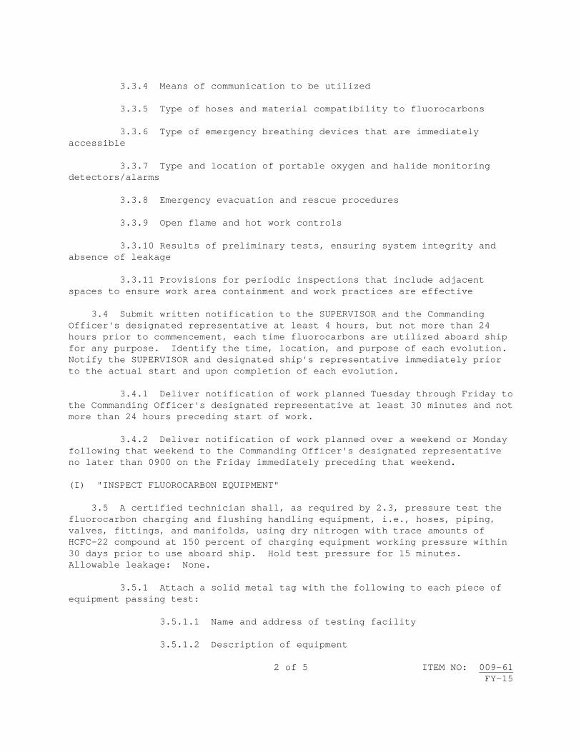
2 of 5 ITEM NO: 009-61 FY-15
3.3.4 Means of communication to be utilized 3.3.5 Type of hoses and material compatibility to fluorocarbons 3.3.6 Type of emergency breathing devices that are immediately accessible 3.3.7 Type and location of portable oxygen and halide monitoring detectors/alarms 3.3.8 Emergency evacuation and rescue procedures 3.3.9 Open flame and hot work controls 3.3.10 Results of preliminary tests, ensuring system integrity and absence of leakage 3.3.11 Provisions for periodic inspections that include adjacent spaces to ensure work area containment and work practices are effective 3.4 Submit written notification to the SUPERVISOR and the Commanding Officer's designated representative at least 4 hours, but not more than 24 hours prior to commencement, each time fluorocarbons are utilized aboard ship for any purpose. Identify the time, location, and purpose of each evolution. Notify the SUPERVISOR and designated ship's representative immediately prior to the actual start and upon completion of each evolution. 3.4.1 Deliver notification of work planned Tuesday through Friday to the Commanding Officer's designated representative at least 30 minutes and not more than 24 hours preceding start of work. 3.4.2 Deliver notification of work planned over a weekend or Monday following that weekend to the Commanding Officer's designated representative no later than 0900 on the Friday immediately preceding that weekend. (I) "INSPECT FLUOROCARBON EQUIPMENT" 3.5 A certified technician shall, as required by 2.3, pressure test the fluorocarbon charging and flushing handling equipment, i.e., hoses, piping, valves, fittings, and manifolds, using dry nitrogen with trace amounts of HCFC-22 compound at 150 percent of charging equipment working pressure within 30 days prior to use aboard ship. Hold test pressure for 15 minutes. Allowable leakage: None. 3.5.1 Attach a solid metal tag with the following to each piece of equipment passing test: 3.5.1.1 Name and address of testing facility 3.5.1.2 Description of equipment

3 of 5 ITEM NO: 009-61 FY-15
3.5.1.3 Date of test 3.5.1.4 Test pressure (I)(G) "INSPECT WORK SITE AND PROCESS PRIOR TO FLUOROCARBON OPERATIONS" 3.6 Inspect work site to ensure the following prior to fluorocarbon operations: 3.6.1 Provide ventilation to maintain oxygen content above 19.5 percent and not greater than 22.0 percent by volume in spaces where fluorocarbon compounds are in use. 3.6.2 Establish and maintain telephone communication between the pumping station and the space involved when the fluorocarbon compound is being transferred by hose or pipe. 3.6.3 Ensure that all personnel in a space where fluorocarbon operations are being carried out have an emergency escape breathing device (EEBD) in their possession or in the immediate area so that they can quickly don the units in case of a leak. 3.6.3.1 Each person shall have received instruction and practice in the use of the particular EEBD to be used, prior to entering each space where fluorocarbon operations are being carried out. 3.6.4 Suspend hot work in spaces prior to hook-up, test, and disconnect operations in which fluorocarbon compounds are exposed to the atmosphere. 3.6.4.1 Hot work is permitted in spaces traversed by lines carrying fluorocarbon compounds provided the lines are clearly tagged and no hot work is attempted within 3 feet of a tagged line. 3.6.5 Provide a halide monitor with alarm or equivalent instrument to continuously monitor the atmosphere in spaces where fluorocarbon compounds are used. If the concentration of fluorocarbon compound in the space exceeds the Threshold Limit Value (TLV) for the fluorocarbon compound (where the instrument is set to alarm), clear the space of personnel, notify Quarterdeck Watch immediately and the SUPERVISOR as soon as practical but not more than 30 minutes after the instrument alarms. 3.6.6 Post a caution sign in the area and at each entrance to the area. 3.6.6.1 The sign shall read: CAUTION: No open flames. Do not enter without testing the air for fluorocarbons. 3.6.6.2 The sign letters shall be at least one-inch high.

4 of 5 ITEM NO: 009-61 FY-15
3.6.7 Provide a minimum of 2 people trained and familiar with the operation while a fluorocarbon compound is being used in quantities exceeding 10 pounds. 3.7 Accomplish preliminary pressure tests of charging/flushing equipment after connecting aboard ship each time equipment is used. Pressure shall equal 100 percent of charging/flushing equipment working pressure. Hold test pressure for 15 minutes. Allowable leakage: None. 3.7.1 Ensure charging equipment is isolated from equipment to be charged prior to test. 3.8 A certified technician shall, as required by 2.4, ensure that fluorocarbon gases are not vented to the interior of the ship or to the atmosphere when pressure is released from the system by utilizing reclaiming/recycling equipment tested and certified by an Environmental Protection Agency (EPA) approved laboratory or organization. 3.8.1 Collect CFCs and HFCs for either recycling back into the same system/piece of equipment from which the material was removed or recovering the CFCs for turn-in. 4. NOTES: 4.1 Following are examples of commonly used fluorocarbon compounds: Trichlorofluoromethane, Freon 11, R-11 (CFC-11) Dichlorodifluoromethane, Freon 12, R-12 (CFC-12) Chlorotrifluoromethane, R-13 (also component of R-503) (CFC-13) Pentachlorofluoroethane (CFC-111) Tetrachlorodifluoroethane (CFC-112) 1,1,2 Trichloro-1,2,2 Trifluoroethane, Freon 113, Freon TF, Freon PCA, Genetron 113 (CFC-113) 1,2 Dichlorotetrafluotethane, R-114, Freon 114 (CFC-114) Chloropentafluoroethane, R-115 (also component of R-502) (CFC-115) Heptachlorofluoropropane (CFC-211) Hexachlorodifluoropropane (CFC-212) Pentachlorotrifluoropropane (CFC-213) Tetrachlorotetrafluoropropane (CFC-214) Trichloropentafluoropropane (CFC-215) Dichlorohexafluoropropane (CFC-216) Chloroheptafluoropropane (CFC-217) Tetrafluoroethane (HFC-134a) 4.2 EEBD equipment for Government representatives will be provided by the Government. 4.3 ODS material must be procured as Government Furnished Material (GFM) from the DOD ODS Reserve. Notify the SUPERVISOR at least 14 working days prior to anticipated usage.
5 of 5 ITEM NO: 009-61 FY-15
4.4 The following definitions are delineated by Navy policy: 4.4.1 Recover - To remove refrigerant in any condition from a system and store it in an external container without necessarily testing or processing it in any way. 4.4.2 Recycle - To reduce contaminants in used refrigerant by oil separation and single or multiple passes through devices such as replaceable core filter dryers that reduce moisture, acidity and particulate matter. The term usually applies to procedures implemented at the field job site or at a local service shop. 4.4.3 Reclaim - To reprocess refrigerant to new product specifications by means that may include distillation. Chemical analysis of the refrigerant is required to determine that appropriate product specifications are met. This usually implies the use of processes or procedures that are available only at refrigerant reprocessing or manufacturing facilities.


1 of 3 ITEM NO: 009-62 FY-15
NAVSEA STANDARD ITEM FY-15 ITEM NO: 009-62 DATE: 29 JUL 2011 CATEGORY: II 1. SCOPE: 1.1 Title: Boiler Handhole and Manhole Seats and Plates; inspect 2. REFERENCES: 2.1 S9221-C1-GTP-010, Repair and Overhaul Main Propulsion Boiler 2.2 803-841216, Handhole Plates and Arch Bars for Boilers 3. REQUIREMENTS: 3.1 Remove handhole and manhole plates from headers and drums of boilers. Plates shall be identified and tagged as to respective boilers. 3.2 Wire brush clean to bare metal handhole and manhole plates, studs, strongbacks, and fasteners. Wire brush clean to bare metal handhole and manhole gasket seating surfaces using a power driven wire cup brush. Ensure complete removal of rust and gasket material. 3.2.1 Wire brush clean to bare metal external surfaces in way of "B" and "C" measurement contact areas using a power-driven wire wheel or needle gun. 3.3 Visually inspect gasket seating surfaces of handhole and manhole plates and the drum and header for erosion, corrosion, gouges, steam cuts, crack indications, excessive pitting, grooves, and any irregularities that may cause poor or leaky joints. Inspect external surfaces of headers in way of "B" and "C" measurement areas for erosion and corrosion. Inspect studs and nuts for deterioration and damaged and stripped threads. 3.3.1 Visually inspect, measure, and record the following handhole and manhole gasket seating surface criteria in accordance with Paragraph 5-8.2 of 2.1 and Attachment A. 3.3.1.1 Seat taper: Use template of flat stock and feeler gage to measure maximum taper around periphery of handhole and manhole seats. 3.3.1.2 Minimum wall thickness: Measure header wall thickness using a point micrometer at each side of the header cross sectional minor axis.

2 of 3 ITEM NO: 009-62 FY-15
3.3.1.3 Minimum seat thickness: Measure header seat thickness with a flat-faced micrometer at the 4 points of the header cross sectional major and minor axis. 3.3.1.4 Handhole Plate Overlap: Measure maximum gap clearance between shoulder of the handhole plate and handhole with handhole plate located in the most extreme misaligned position. Subtract the measurement from the plate seat width to establish the amount of plate overlap. Handhole plates used for measurements shall conform to 2.2. 3.3.1.5 Manhole Plate Clearance: Measure clearance between shoulder of manhole plate and manhole at 8, 45-degree increments, with the manhole plate accurately centered. 3.4 Submit one legible copy, in approved transferrable media, of a report listing results of the requirements of 3.3 to the SUPERVISOR. Report shall list each handhole and manhole seat which failed to meet the minimum allowable values listed in Appendices 5D, 5E, and 6C of 2.1. 3.5 Install handhole and manhole plates, using new gaskets conforming to MIL-G-15342 and applicable boiler technical manual. 4. NOTES: 4.1 Equipment technical manual will be listed in the invoking Work Item.

3 of 3 ITEM NO: 009-62FY-1
ATTACHMENT A


1 of 4 ITEM NO: 009-63 FY-15
NAVSEA STANDARD ITEM FY-15 ITEM NO: 009-63 DATE: 29 JUL 2011 CATEGORY: II 1. SCOPE: 1.1 Title: Lubricating Oils and Hydraulic Fluids; analyze 2. REFERENCES: 2.1 S9086-H7-STM-010/CH-262, Lubricating Oils, Greases, Specialty
Lubricants, and Lubrication Systems 2.2 S9086-S4-STM-010/CH-556, Hydraulic Equipment (Power Transmission and
Control) 2.3 S9086-HB-STM-010/CH-233, Diesel Engines 3. REQUIREMENTS: 3.1 Provide samples (lubricant oil or hydraulic fluids) to a certified laboratory as listed in Table 262-4-2 of 2.1. 3.2 Accomplish tests of each sample in accordance with the specified test methods of Attachment A or Attachment B. 3.2.1 Test selections shall be based on the sample type and service. 3.3 Analyze samples for metal content and water contamination by utilizing a spectrographic analysis in accordance with ASTM D-6595. 3.3.1 Determine if water contamination is fresh or salt water based on high sodium levels. 3.3.2 Record and report the concentration of the following elements in ppm with the indicated degree of accuracy:
IRON COPPER TIN MAGNESIUM LEAD
ALUMINUM SILVER CHROMIUM NICKEL SILICON
SODIUM

2 of 4 ITEM NO: 009-63 FY-15
3.3.2.1 The sensitivity and reliability of the equipment used for the test shall be in accordance with ASTM D-6595. 3.4 Accomplish specific gravity test for each MIL-H-19457 hydraulic fluid sample and determine hydrocarbon oil content in accordance with Table 556-8-1 of 2.2. 3.5 Submit one legible copy, in hard copy or approved transferrable media, of a report listing completed test results of 3.2 through 3.4 for each sample to the SUPERVISOR. 3.5.1 Reports shall be submitted within 48 hours after the qualified chemical laboratory receives each sample. 3.5.2 Reports shall include recommendations for continued use, disposal, or re-sampling of each tested oil or fluid sample. 3.6 Use Table 262-4-1 of 2.1 and Table 556-8-1 of 2.2 for guidance for test accept and reject criteria for each in-service sample. 3.6.1 Use Table 233-8-2 of 2.3 for test accept and reject criteria for 9000 Series lube oil/MIL-PRF-2104 lube oil. 3.7 Submit one legible copy, in hard copy or approved transferrable media, of original manufacturer's certificate of compliance and material conformance test data in accordance with Military Specifications listed in Attachment A and Attachment B, 7 working days prior to use of new fluids and oils. 4. NOTES: 4.1 Ship's Force will label all samples in accordance with 2.1 and 2.2.

X -- IDENTIFIES EACH TEST REQUIRED FOR EACH FLUID TYPE 3 of 4 ITEM NO: 009-63 FY-15
ATTACHMENT A LUBRICATING OILS
ASTM TEST
METHOD
MIL-PRF-17672 MS-2075-TH MS-2110-TH MS-2135-TH
MIL-PRF-17331 MS-2190-TEP
MIL-PRF-9000 9250
MIL-PRF-2104
15W/40 MIL-PRF-23699 VV-L-825
FUEL DILUTION VIA FLASH POINT
ASTM D93
X X
PERCENT WATER
ASTM D6304 X X X X
VISCOSITY
ASTM D445 X X X X
ACID NO.
ASTM D974 X X X X X
TOTAL BASE NO.
ASTM D2896 X X
SPECTROGRAPHIC ANALYSIS
ASTM D6595
X X X X X X

X -- IDENTIFIES EACH TEST REQUIRED FOR EACH FLUID TYPE 4 of 4 ITEM NO: 009-63 FY-15
ATTACHMENT B HYDRAULIC FLUIDS
ASTM TEST
METHOD MIL-DTL-17111 MIL-H-19457
MIL-PRF-2104 MIL-PRF-17672 MS-2075-TH MS-2110-TH MS-2135-TH
MIL-PRF-17331 MS-2190-TEP
MIL-H-22072
FLASH POINT
ASTM D92 X X
PERCENT WATER
ASTM D95 X
PERCENT WATER
ASTM D6304 X X X X
VISCOSITY
ASTM D445 X X X
ACID NO.
ASTM D974 X X X X
PARTICLE COUNT
NAS/SAE 4059
(Automatic Particle Count Method)
X X X X X

1 of 2 ITEM NO: 009-64 FY-15
NAVSEA STANDARD ITEM FY-15 ITEM NO: 009-64 DATE: 29 JUL 2011 CATEGORY: I 1. SCOPE: 1.1 Title: Synthetic Fire-Resistant Hydraulic Fluid; control 2. REFERENCES: 2.1 None. 3. REQUIREMENTS: 3.1 Accomplish the following for control of MIL-H-19457 and/or MIL-H-22072 Synthetic Fire-Resistant Hydraulic Fluid: 3.1.1 Monitor and exercise positive control of accesses to and egresses from areas in which the hydraulic fluid is being handled. 3.1.1.1 Post warning signs at entrances and in work areas (2-inch minimum letters on signs) stating: CAUTION: SYNTHETIC FIRE-RESISTANT HYDRAULIC FLUID HANDLING. UNAUTHORIZED PERSONNEL KEEP OUT. 3.1.1.2 All areas shall be roped off or otherwise secured and identified. 3.1.2 Hydraulic fluid shall be contained and immediately cleaned up in event of spill. 3.1.2.1 Rags in sufficient quantity shall be on hand to clean up and control spills. 3.1.2.2 Plastic bags for disposal of oily rags shall be available and partially filled or filled bags removed at the end of each shift. 3.1.2.3 Used fluid shall be pumped into drums stenciled: USED SYNTHETIC FLUID, for disposal. 3.1.3 Requirements for handling: 3.1.3.1 In addition to normal personal protective equipment (PPE), rubber gloves, face shields, and rubber aprons shall be used by personnel handling fire-resistant hydraulic fluid.

2 of 2 ITEM NO: 009-64 FY-15
3.1.3.2 Spills on clothing shall be cause to remove clothing and rinse in fresh water. 3.1.3.3 Spills on skin shall be washed with soap and rinsed with fresh water. 3.2 Report verbally each spill in excess of 5 gallons as soon as management becomes aware of such an event. 3.2.1 Submit one legible copy, in approved transferrable media, of a formal written report of the event to the SUPERVISOR within 24 hours. 3.3 Upon completion of work the contractor shall notify the SUPERVISOR in writing of the completion of the work, certifying that the area is cleaned and that the area is safe to enter. 4. NOTES: 4.1 None.

1 of 1 ITEM NO: 009-65 FY-15
NAVSEA STANDARD ITEM FY-15 ITEM NO: 009-65 DATE: 29 JUL 2011 CATEGORY: I 1. SCOPE: 1.1 Title: Polychlorinated Biphenyls (PCBs); control 2. REFERENCES: 2.1 40 CFR Part 761, Polychlorinated Biphenyls (PCBs) Manufacturing,
Processing, Distribution in Commerce, and Use Prohibitions 2.2 Toxic Substances Control Act (TSCA) 3. REQUIREMENTS: 3.1 Visually inspect equipment suspected of containing PCBs for leaks, deterioration, and corrosion prior to opening, removing, or installing equipment. 3.1.1 Submit one legible copy, in approved transferrable media, of a report listing results of the inspection conducted in 3.1 to the SUPERVISOR if PCBs are identified. 3.2 Consider wool felt to contain PCBs and chromium. 3.2.1 Submit one legible copy, in approved transferrable media, of a report listing the type of wool felt (gasket or damping material), location, and approximate quantity to the SUPERVISOR. 3.3 Provide a copy of a control, method of removal, and disposal plan in accordance with 2.1 and/or 2.2 to the SUPERVISOR. 4. NOTES: 4.1 None.


1 of 3 ITEM NO: 009-66 FY-15
NAVSEA STANDARD ITEM FY-15 ITEM NO: 009-66 DATE: 17 JAN 2013 CATEGORY: II 1. SCOPE: 1.1 Title: Light-Off Assessment (LOA) Support for Diesel Propulsion
System; provide 2. REFERENCES: 2.1 None. 3. REQUIREMENTS: 3.1 Complete work in the main propulsion machinery spaces, steering gear room, shaft alleys, pump rooms, auxiliary machinery rooms, and designated fuel tanks prior to the scheduled Light-Off Assessment (LOA). For availabilities in excess of 120 days (140 days for forward deployed CVNs), Propulsion Plant Production Completion Date (PCD) will be scheduled 14 days prior to the LOA. For availabilities 120 days or less (140 days for forward deployed CVNs), PCD will be scheduled between 4-14 days prior to propulsion plant light-off. Repairs, installations, testing, and adjustments of auxiliary machinery, systems, and equipment outside those spaces which support the main propulsion system directly, indirectly, or for emergencies shall also be completed. 3.1.1 The term complete is defined to mean the accomplishment of all contractor responsible work, testing, and certification that is possible without lighting off the main propulsion diesel engines until after a successful Light-Off Assessment. 3.1.2 The following work shall be complete: 3.1.2.1 Repair and installation of machinery, equipment, blowers, piping systems, gages, thermometers, meters, operating instructions and warning plates, protective guards, flange shields, remote shutdown devices, strainer shields, valves and handwheels, insulation and lagging, check valves, steam traps and orifices, regulators and reducing valves, remote operating gear and pull cables, valve reach rods, pipe hangers and braces, valve locking devices, valve position indicators, indicators, gage lines, label plates, relief valves and hand lifting levers, sight glasses and guards, fuel strainers, firefighting systems and equipment, handrails, ladders, access doors and scuttles, ventilation systems, supply and exhaust vent screens, lighting systems (incandescent, fluorescent, and emergency

2 of 3 ITEM NO: 009-66 FY-15
battle lanterns), electric cables and runs, cable straps, cable packing, cable tags, alarm systems, ground straps, flex hoses, resilient mounts, safety devices, stenciling, interior communication systems, tachometers, and resiliently-mounted pipe hangers. 3.1.2.2 Calibration of gages, thermometers, tachometers, pyrometers, and meters. 3.1.2.3 Cold setting of relief valves, diesel engine governors, overspeed trips, piping spring hangers, regulators and reducing valves, high temperature alarms and switches, high and low pressure control switches, and low lube oil pressure alarms. 3.1.2.4 Painting. 3.1.2.5 Filling of lube oil, fuel oil, and freshwater tanks. 3.1.2.6 Bilges shall be clean and gas free, "Safe for Workers." 3.1.3 Complete portions of required test procedures that can be completed without diesel engine light-off. 3.2 Correct contractor responsible preliminary LOA discrepancies prior to the turnover of engineering spaces to Ship's Force. The time period after PCD and prior to the LOA is reserved for Ship's Force preparation for LOA. Contractor work will not be allowed in the engineering spaces during this period unless specifically authorized by the SUPERVISOR. 3.2.1 Submit one legible copy, in approved transferrable media, of a weekly report on the status of completion of preliminary LOA discrepancies. Notify the SUPERVISOR immediately upon determination of any discrepancies that cannot be corrected prior to the scheduled LOA, giving the reason and expected completion date. 3.3 Provide the services of a contractor quick response team during the LOA to correct Government and contractor discrepancies. 3.3.1 Coordinate the correction of discrepancies as they are discovered at the direction of the SUPERVISOR. 3.3.2 The quick response team members shall have with them (or readily accessible), the tools of their trade for immediate use in the correction of discrepancies.

3 of 3 ITEM NO: 009-66 FY-15
4. NOTES: 4.1 The LOA is a comprehensive assessment of the ship in the key areas of: The level of knowledge and firefighting capability of propulsion plant personnel; the adequacy of Engineering Department administrative programs and procedures; the material readiness of the propulsion plant; and the state of cleanliness and preservation of main propulsion and auxiliary machinery spaces. The LOA will be accomplished by the Immediate Superior in Command (ISIC), Afloat Training Group (ATG) or the Type Commander Staff. The assessment will be conducted immediately prior to scheduled diesel engine light-off and it must be concluded successfully prior to diesel engine light-off. The material assessment portion usually takes less than 12 hours. If restrictive discrepancies are identified, those discrepancies must be corrected prior to diesel engine light-off. 4.2 The SUPERVISOR will establish an inspection team and accomplish a preliminary LOA inspection in conjunction with Ship's Force 4 to 8 weeks prior to the LOA to determine and record discrepancies which would impact upon the LOA. The pre-LOA will be about 4 days in duration and will result in the identification of discrepancies and incomplete work considered necessary to support a successful Light-Off Assessment. Each discrepancy noted in the inspection will be described in simple terms on a 4-part, serialized form. The form will identify the general location of the discrepancy and the associated work Item number, if applicable. The fourth copy of the form, made of hard card with an attachment wire, will be hung by the SUPERVISOR'S inspection team in the immediate proximity of the discrepancy (on the deficient item itself, when practical). Upon completion of the pre-LOA the SUPERVISOR will identify contractor responsible discrepancies to the contractor. Deficient items identified that are the responsibility of the Government will be screened for accomplishment by the Ship's Force. That portion of this work that cannot be accomplished by the Ship's Force will be considered for accomplishment by the contractor. 4.2.1 Any time after completion of the pre-LOA inspection that additional discrepancies are discovered, they will be similarly identified and screened.


1 of 5 ITEM NO: 009-67 FY-15
NAVSEA STANDARD ITEM FY-15 ITEM NO: 009-67 DATE: 17 JAN 2013 CATEGORY: I 1. SCOPE: 1.1 Title: Integrated Total Ship Testing; manage 2. REFERENCES: 2.1 S9AAO-AB-GOS-010, General Specifications for Overhaul of Surface
Ships (GSO) 2.2 S9095-AD-TRQ-010/TSTP, Total Ship Test Program 3. REQUIREMENTS: 3.1 Prepare and manage a Comprehensive Test Plan (CTP) in accordance with Section 092c of 2.1, using 2.2 for guidance. 3.1.1 Define and document the responsibility, lines of authority, and interrelation of personnel who manage, perform, or verify work. 3.1.2 Include a schedule of the restoration of ship's installed services to support completion of Stage 5 testing. 3.1.3 Include a procedure for reporting problems in delivery dates of the Contractor furnished material (CFM), Government furnished material (GFM), Government furnished equipment (GFE), and Government furnished information (GFI) for ship's systems. 3.1.4 Include organizational responsibility for equipment and system installation, repair, maintenance, start-up, operation, and test. 3.1.5 Submit one legible copy, in approved transferrable media, of the CTP to the SUPERVISOR not later than 15 working days prior to availability start date. 3.2 Develop an Integrated Total Ship Test Plan, using contracted work package and available GFI. 3.2.1 Include a shipyard Test Sequence Network (TSN) and test schedule, with Government and Contractor responsibilities defined.

2 of 5 ITEM NO: 009-67 FY-15
3.2.2 Include required external services, with Government and Contractor responsibilities. 3.2.3 Include a list of necessary test equipment and software, with required dates and responsible provider. 3.2.4 Include organizational responsibility for equipment operation and accomplishment of testing, including Government and Contractor manning requirements. 3.2.5 Include a list of SUPERVISOR, contractor, Alteration Installation Team (AIT), and Ship's Force key test team personnel, with test sign-off authority. 3.2.6 Include administrative procedures for submittal of Test Problem Reports (TPRs), Test Procedures (TPs), Test Failure Reports (TFRs), and test status. 3.2.7 Include identification and display of the combat system critical path for testing. 3.2.8 Include provision for completion of total ship testing through Stage 5 prior to dock trials. 3.2.9 Define the requirements of both Contractor and Government for general and special purpose test equipment, weapon test shapes, dummy loads, and test weights, to accomplish total ship testing. Identify known and anticipated deficiencies in required type, quantity, calibration, or availability, to support the production or test schedule. 3.2.10 Submit one legible copy, in approved transferrable media, of the Test Plan to the SUPERVISOR at the start of the availability. 3.3 Develop and manage a Total Ship Testing Task Group. 3.3.1 The group shall consist of representatives of the SUPERVISOR, Contractor, AIT Team(s) on scene, Ship's Force, and shall meet as requested by the SUPERVISOR. 3.3.2 The SUPERVISOR’s representative shall act as Chairman. 3.3.2.1 Provide an updated Total Ship Test Plan and status of Total Ship Testing including growth and new work. Document problems impeding progress of meeting scheduled dates or of satisfying technical requirements. 3.3.2.2 Maintain minutes and agendas. Minutes shall include a list of attendees, action items with assignments, highlights of proceedings, and identified problems with their potential impact.

3 of 5 ITEM NO: 009-67 FY-15
3.3.2.3 Submit one legible copy, in approved transferrable media, of the minutes and updated Test Plan to the members not later than 2 working days after each meeting. 3.4 Manage Total Ship Testing. 3.4.1 Accomplish the requirements of the Test Plan of 3.2. 3.4.2 Coordinate testing in accordance with the Test Plan. 3.4.3 Coordinate stationing of test personnel in accordance with the Test Plan. Provide test procedures and test data sheets to test personnel. 3.4.4 Coordinate the performance of each test procedure and the recording of each test result on data sheet provided in Attachment A. 3.4.4.1 Ensure sufficient information is provided on the comment sheet for any identified discrepancy, including corrective action. 3.4.4.2 Submit one legible copy, in hard copy or approved transferrable media, of completed data sheets and test procedures for each test in accordance with the Test Plan to the SUPERVISOR within 5 working days of test completion. Include the documentation of each test procedure not completed, and reasons for incompletion. 3.4.5 Coordinate preparations for sea trials. 3.4.6 Develop a test status program completion report that summarizes the results of the Total Ship Test Plan (TSTP) in accordance with Paragraph 3.6 of 2.2. 3.4.6.1 Provide the rationale for test procedures not attempted, incomplete, or failed. 3.4.6.2 Provide details and status of test procedures that were completed with discrepancies. 3.4.7 Submit one legible copy, in hard copy or approved transferrable media, of the test status report to the SUPERVISOR not later than 5 working days after completion of availability. 4. NOTES: 4.1 The ship's Commanding Officer will provide personnel for recording data during Ship's Force/Government responsible total ship testing. 4.2 GFI required to develop the Test Plan may include: Integrated Test Package (ITP), Total Ship's Test Requirements Index (TSTR), Test Index, Test Summary, and known AIT test requirements.

4 of 5 ITEM NO: 009-67 FY-15
4.3 Stage 5 testing is that testing normally conducted between 2 or more sub-elements within the combat, mobility, support, or containment areas of the ship.

5 of 5 ITEM NO: 009-67 FY-15
ATTACHMENT A
TEST PERFORMANCE, RESPONSIBILITY/WITNESS RECORD TEST PROCEDURE: TITLE: SHIP'S NAME: HULL NO.: TEST PERFORMANCE
TEST RESULTS / STATUS (Check all that apply) Complete Failed Complete w/Discrepancies Not attempted Incomplete Aborted If TPR issued TPR #: Comments: TEST RESPONSIBILITY / WITNESS Test performed by: Contractor Ship’s Force Government Print and Sign Name: Position and Responsibility: If SF/GOV: Ship/Agency Name: Dept/Code: Tel/Fax Number: Test witnessed by: Contractor Ship’s Force Government Print and Sign Name: Position and Responsibility: If SF/GOV: Ship/Agency Name: Dept/Code: Tel/Fax Number: Test record reviewed by: SUPERVISOR (Only) Print and Sign Name: Position and Responsibility: Tel/Fax Number:


1 of 5 ITEM NO: 009-68 FY-15
NAVSEA STANDARD ITEM FY-15 ITEM NO: 009-68 DATE: 29 JUL 2011 CATEGORY: II 1. SCOPE: 1.1 Title: Bolted Bonnet Valve; repair 2. REFERENCES: 2.1 S9086-CJ-STM-010/CH-075, Fasteners 2.2 T9074-AS-GIB-010/271, Requirements for Nondestructive Testing Methods 2.3 MIL-STD-2035, Nondestructive Testing Acceptance Criteria 2.4 S9253-AD-MMM-010, Maintenance Manual for Valves, Traps, and Orifices
(Non-Nuclear), User's Guide and General Information 3. REQUIREMENTS: 3.1 Matchmark valve parts. (V) "INSPECT PARTS FOR DEFECTS" 3.2 Disassemble, clean free of foreign matter (including paint), and inspect parts for defects. 3.2.1 The removal of body-bound studs only to determine the condition of threads is not required. 3.2.1.1 Exposed portion of body-bound studs shall be inspected in accordance with Section 075-8.3 of 2.1. (I) or (V) “TORQUE TEST” (See 4.3) 3.2.2 Torque test each body-bound stud in accordance with Section 075-8.6.3.2(d) of 2.1. (I) "LIQUID PENETRANT INSPECT" 3.2.3 Accomplish liquid penetrant inspection of seats (including back seat), discs, or gate in accordance with 2.2.

2 of 5 ITEM NO: 009-68 FY-15
3.2.3.1 Acceptance criteria shall be in accordance with Paragraph 7 of 2.3, except hairline cracks in hard-faced areas of seats and discs or gate are acceptable provided the valve does not show evidence of leakage. 3.3 Repair valve as follows: 3.3.1 Straighten stem to within 0.002-inch total indicator reading. Polish stem to a 32 Root-Mean-Square finish in way of packing surface and remove raised edges and foreign matter. 3.3.2 Chase and tap exposed threaded areas. 3.3.3 Clean and spot-in bonnet to body gasket mating surfaces. 3.3.4 Machine, grind, or lap and spot-in gate or discs to seats (including back seat) to obtain a 360-degree continuous contact. (V) "INSPECT CONTACT" 3.3.4.1 Inspect contact using blueing method. 3.3.4.2 Transfer line for gate valve shall not exceed 3/16 inch in width and shall appear within the lower 75 percent of the gate seating surface. 3.3.4.3 Transfer line for globe valve shall not exceed 1/16 inch in width. (I)(G) "VERIFY LEVEL I PARTS" 3.4 Assemble valve, installing new gaskets in accordance with the manufacturer's specifications, using new fasteners for those removed in 3.2, in accordance with Attachment A, or for DDG-51 class, Attachment B. 3.4.1 Pack feedwater, condensate, and steam valves with valve stem packing conforming to MIL-P-24503/24583 combination in accordance with Chapter 6 of 2.4. 3.4.2 Pack valves of systems other than feedwater, condensate, or steam with valve stem packing conforming to MIL-P-24396, Type B. 4. NOTES: 4.1 Operational test of valve will be specified in Work Item. 4.2 Repair of valve operating gear will be specified in Work Item. 4.3 The paragraph referencing this note is considered an (I) if the valve is Level I. If the valve is not Level I, the paragraph is considered a (V).

3 of 5 ITEM NO: 009-68 FY-15
ATTACHMENT A VALVE BODY MATERIAL
1/ Alloy Steel
Carbon Steel
2/ Nonferrous
3/ Studs and Bolts to MIL-DTL-1222
Grade B-16
Grade B-16
Phosphor Bronze - Any Grade Silicon Bronze - Any Grade Nickel Copper - Class A 4/
Nuts to MIL-DTL-1222
Grade 4 or 7 Grade 4 or 7 Phosphor Bronze - Any Grade Silicon Bronze - Any Grade Nickel Copper - Class A or Class B 5/
Socket Head Cap Screws
FF-S-86 FF-S-86
1/ Alloy steel is of Composition A - 2-1/4 percent Chromium, one percent
Molybdenum, Composition B - 1-1/4 percent Chromium, 1/2 percent Molybdenum, and Composition C - Carbon Molybdenum.
2/ Nonferrous Alloy except Aluminum. 3/ Studs shall be Class 2 or 3 fit on the nut end and Class 5 fit on the stud
and, except that a Class 3 fit with a thread locking compound may be used where temperatures do not exceed 250 degrees Fahrenheit. The thread locking compound shall conform to ASTM D 5363. Check Class 3 fit stud ends in accordance with SAE-J2270.
4/ Fasteners of Nickel Copper Aluminum shall be the only type used on sea
chest and hull valves. 5/ Nuts of Nickel Copper Alloy, conforming to QQ-N-281 Class A or B, or
Nickel Copper Aluminum conforming to QQ-N-286 shall be the only type used on sea chest and hull valves.

4 of 5 ITEM NO: 009-68 FY-15
ATTACHMENT B VALVE BODY MATERIAL
1/ Alloy Steel/Carbon Steel
2/ Nonferrous
3/ Studs and Bolts to MIL-DTL-1222
5/ For services up to and including 650 degrees Fahrenheit; Grade 5 steel
4/ 5/ Phosphor Bronze - Any Grade Silicon Bronze - Any Grade Nickel Copper - Class A
For services to 775 degrees Fahrenheit; Grade B-7 or B-16
For services to 1,000 degrees Fahrenheit; Grade B-16
For services in which JP-5 lubricating oil, or inflammable gas or liquid of any kind, regardless of pressure and temperature, which are within 3 feet of hot surfaces (above 650 degrees F) and where steel tubing is required; Grade 2, 5 or 8 steel
Bolting subject to seawater corrosion (other than hull integrity bolting; for hull integrity bolting see Note 4) Connections in contact with bilge regions. Where strength requires ferrous bolting and is exposed to the weather; Class A Nickel - Copper alloy to QQ-N-281 or silicon bronze to ASTM B 98 with dimensions of MIL-DTL-1222. Where greater strength is required, use Nickel - Copper - Aluminum alloy QQ-N-286.
Nuts to MIL-DTL-1222
5/ For services up to and including 650 degrees Fahrenheit; Grade 5 steel
Phosphor Bronze - Any Grade Silicon Bronze - Any Grade Nickel Copper - Class A or Class B 4/ 5/
For service to 775 degrees Fahrenheit; Grade 2H or 4 steel
For services to 1,000 degrees Fahrenheit; Grade 4 steel

5 of 5 ITEM NO: 009-68 FY-15
ATTACHMENT B (Con't)
1/ Alloy Steel/Carbon Steel
2/ Nonferrous
For services in which JP-5, lubricating oil, or inflammable gas or liquid of any kind, regardless of pressure and temperature which are within 3 feet of hot surfaces (above 650 degrees F) and where steel tubing is required; Grade 5 or 8 steel
Nuts subject to seawater corrosion. Connections in the bilge regions. Where strength requires ferrous material and is exposed to the weather; Class A or B Nickel Copper Alloy to QQ-N-281 or Silicon Bronze to ASTM B 98 with dimensions to MIL-DTL-1222
NOTES 1/ Alloy steel is of Composition A - 2-1/4 percent Chromium, one percent
Molybdenum, Composition B - 1-1/4 percent Chromium, 1/2 percent Molybdenum, and Composition C - Carbon Molybdenum.
2/ Nonferrous Alloy except Aluminum. 3/ Studs shall be Class 2 or 3 fit on the nut end and Class 5 fit on the stud
end, except that a Class 3 fit with a thread locking compound may be used where temperatures do not exceed 200 degrees Fahrenheit. The thread locking compound shall conform to ASTM D 5363. Check Class 3 fit stud ends in accordance with SAE-J2270.
4/ Fasteners of Nickel Copper Aluminum shall be the only type used on sea
chest and hull valves. 5/ Where these materials would constitute part of a galvanic couple,
proposals for alternate materials shall be submitted for approval.


1 of 12 ITEM NO: 009-69 FY-15
NAVSEA STANDARD ITEM
FY-15 ITEM NO: 009-69 DATE: 07 NOV 2013 CATEGORY: I 1. SCOPE: 1.1 Title: Heavy Weather Plan; provide 2. REFERENCES: 2.1 845-6686999 Rev E, US Navy Vessel Water Depth, Mooring and
Hull/Appendage Clearance Requirements for Transit and Berthing 2.2 DDS 582-1, Design Data Sheet, Calculations for Mooring Systems 2.3 S9086-TW-STM-010/CH-582, Mooring and Towing 2.4 UFC 4-159-03, Mooring Design 3. REQUIREMENTS: 3.1 Maintain a written plan that shall be implemented during gales, storms, hurricanes, and destructive weather, including mooring calculations in accordance with 2.1 and 2.2, using 2.3 and 2.4 for guidance. The documented Heavy Weather Plan shall be submitted to the SUPERVISOR for a document review and acceptance. The contractor shall have an acceptable documented Heavy Weather Plan, in accordance with this Standard Item, in place no later than 15 days prior to availability start date. The Heavy Weather Plan shall be subject to periodic conformity audits by the SUPERVISOR throughout the contract. 3.1.1 Submit updated or changed plans to the SUPERVISOR as they occur. 3.2 Ensure that the plan designates responsibility and implements procedures for prevention of damage to naval ships, craft, barges, and lighters. This includes periods when ships, craft, barges, and lighters are physically located in private contractors' plants; during times when work on ships, craft, barges, and lighters at naval facilities requires openings to hulls or decks; and when contractor owned/furnished floating equipment is tied alongside ships, craft, barges, and lighters. 3.2.1 The plan shall contain specific responsibilities and detailed actions to be taken during the weather conditions listed below.

2 of 12 ITEM NO: 009-69 FY-15
3.2.2 Conditions where there is substantial advance warning for approaching adverse weather are addressed by the following 4 categories: 3.2.2.1 Gale/Storm/Hurricane Condition IV: Trend indicates a possible threat of destructive winds of force indicated within 72 hours. 3.2.2.2 Gale/Storm/Hurricane Condition III: Destructive winds of force indicated are possible within 48 hours. 3.2.2.3 Gale/Storm/Hurricane Condition II: Destructive winds of force indicated are anticipated within 24 hours. 3.2.2.4 Gale/Storm/Hurricane Condition I: Destructive winds of force indicated are anticipated within 12 hours or less. 3.2.3 Conditions where there is little or no advance warning for approaching adverse weather are addressed by the following 2 categories: 3.2.3.1 Thunderstorm/Tornado Condition II: Destructive winds accompanying the phenomenon indicated are reported or expected in the general area within 6 hours. Lightning and thunder are also anticipated. 3.2.3.2 Thunderstorm/Tornado Condition I: Destructive winds accompanying the phenomenon are imminent. Lightning and thunder are also anticipated. 3.3 Ensure that the plan contains, as a minimum, the following information as dictated by conditions listed in 3.2: 3.3.1 Steps to be taken to remove or secure staging items or equipment on decks of ships, craft, barges, and lighters, pier or dry dock, including cranes that could become wind-borne. 3.3.2 Protection of ships, craft, barges, and lighters from damage from other floating equipment, such as barges, doughnuts, work floats, and other ships, craft, barges, and lighters. 3.3.3 Provisions for protection of government equipment and material in custody of the contractor from damage by pierside flooding. 3.3.4 Provisions for removal of temporary hoses, welding lines, air lines, oxygen/acetylene lines, etc., extending through watertight closures. 3.3.5 Provisions for security, emergency fire and flooding protection, emergency shipboard dewatering and fire main capability, emergency shipboard electrical generation, and emergency shipboard communications. 3.3.5.1 Specific requirements for emergency shipboard fire main capability are shown on Attachment A.

3 of 12 ITEM NO: 009-69 FY-15
3.3.5.2 The minimum requirements for emergency shipboard electrical generation equipment are shown on Attachment B. 3.3.5.3 One portable dewatering pump and associated equipment shall be available adjacent to each damage control equipment box such that 200 gal/min at a discharge head of 50 feet of dewatering capacity can be used at the scene of a casualty within 3 minutes of receiving an alarm. Additional dewatering capacity to provide 1,000 gal/min at a discharge head of 50 feet at the scene shall be available within 15 minutes. During the waterborne overhaul period, no damage control system associated with flooding prevention and control or any portion thereof shall be removed or made inoperable without prior notification of the Supervisor and to the casualty-control station and until a back-up system has been established. 3.3.6 Provisions for access to the ship for personnel and emergency equipment during and immediately following the storm consistent with prudent safety precautions. 3.3.7 Assurance that all hull/deck openings are made watertight. 3.3.8 Steps to be taken to secure floating piers during high winds/high tides. 3.3.9 Provisions for messing contractor, Ship's Force, and SUPERVISOR duty personnel for 3 days (minimum). The maximum number of Navy personnel will be 15. 3.3.10 The name and telephone number (business and residential) of the private contractor's single point of contact. This person shall have the authority to commit the contractor to take necessary actions as requested by the SUPERVISOR. 3.3.11 Provisions for operation and manning of a Hurricane Control Center, with capabilities of telephone and portable radio communications with the ship and SUPERVISOR duty personnel. 3.4 Ensure that the plan contains the following mooring related information: 3.4.1 Specify steps to be taken to secure ships, craft, barges, and lighters to contractor's pier, dry dock, graving dock, marine railway, or contractor's other facility. Information must define specific precautions to be taken and supporting calculations, to include limits of docking blocks and dock stability for both normal and heavy weather conditions. Calculations for heavy weather configurations shall include wind and tidal considerations. 3.4.1.1 Provide the heavy weather state at which the ship must be undocked. 3.4.2 Submit mooring calculations for the worst anticipated loading condition during the availability. For ships with a self-compensating fuel

4 of 12 ITEM NO: 009-69 FY-15
system, the loading condition shall show the self-compensation fuel system full of water, fuel, or some combination of fuel and water, projecting the worse possible condition as shown in calculations for maintaining ship’s stability. Determine the combined loading due to wind load from each direction and both peak flood and ebb current loads at low and high tides. Calculations may require re-submittal if significant changes occur from the original estimate on which the calculations were based. 3.4.3 For ships in dry dock, provide limits and supporting calculations for listed conditions. Analyze both the "normal" dock configuration and the "heavy weather" configuration. 3.4.3.1 Maximum safe wind speed and surge for side block strength and stability. Include maximum loading of the side blocks on ship. 3.4.3.2 Maximum safe wind speed and surge for dry dock strength and stability. 3.4.3.3 Surge required to float ship. 3.4.3.4 Table or graph showing safe combinations of wind speed and surge. 3.4.4 For ships pierside, provide limits and supporting calculations for ship loading conditions specified in 3.4.2. Analyze the "heavy weather" mooring configuration that would be used during the conditions specified in 3.2. Analyze worst-case wind directions including frontal, broadside, and quartering. 3.4.4.1 Maximum safe wind speed for mooring strength. Include strength of pier, pier fittings, mooring lines, and shipboard fittings. Maximum applied load on any mooring line shall be the breaking strength of the mooring line divided by 2.5 (factor of safety of 2.5). 3.4.4.2 Maximum safe surge for mooring. 3.4.4.3 Maximum safe elongation of mooring lines. Include the following information: Size and type of mooring line; Percent elongation of mooring line at failure; Tattletale-free length and length between attachments. 3.4.4.4 Sketch, showing size, type, and location (vertical and horizontal angles) of all securing devices including fenders, bumpers, and camels. 3.4.5 Include the following statement, providing the necessary data: USS __________ can be safely moored to withstand a maximum of ___ mph winds with a __ knot current and a __ foot storm surge.

5 of 12 ITEM NO: 009-69 FY-15
4. NOTES: 4.1 The SUPERVISOR will set Conditions of Readiness consistent with the forecasts and advisories of the local Weather Service Office of National Oceanic and Atmospheric Administration (NOAA). 4.2 NOAA defines the 5 categories of hurricanes as follows: CATEGORY WIND SPEED STORM SURGE 1 74 - 95 MPH OR 4 - 5 FT ABOVE NORMAL 2 96 - 110 MPH OR 6 - 8 FT ABOVE NORMAL 3 111 - 129 MPH OR 9 - 12 FT ABOVE NORMAL 4 130 - 156 MPH OR 13 - 18 FT ABOVE NORMAL 5 157 MPH OR HIGHER OR GREATER THAN 18 FT ABOVE NORMAL 4.3 Attachment C contains regional heavy weather conditions based on historical data and is provided as information only; the historical data is not intended to place limitations/restrictions on other values appropriate and/or previously authorized by a Naval Supervising Activity for their cognizant contractor(s) sites. 4.4 The Heavy Weather Plan submitted in 3.1 requires a one-time submittal/acceptance unless this NAVSEA Standard Item and/or references change or contractor's status changes.
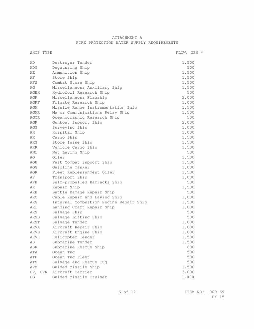
6 of 12 ITEM NO: 009-69 FY-15
ATTACHMENT A
FIRE PROTECTION WATER SUPPLY REQUIREMENTS SHIP TYPE FLOW, GPM * AD Destroyer Tender 1,500 ADG Degaussing Ship 500 AE Ammunition Ship 1,500 AF Store Ship 1,500 AFS Combat Store Ship 1,500 AG Miscellaneous Auxiliary Ship 1,500 AGEH Hydrofoil Research Ship 500 AGF Miscellaneous Flagship 2,000 AGFF Frigate Research Ship 1,000 AGM Missile Range Instrumentation Ship 1,500 AGMR Major Communications Relay Ship 1,500 AGOR Oceanographic Research Ship 500 AGP Gunboat Support Ship 2,000 AGS Surveying Ship 1,000 AH Hospital Ship 1,000 AK Cargo Ship 1,500 AKS Store Issue Ship 1,500 AKR Vehicle Cargo Ship 1,500 ANL Net Laying Ship 500 AO Oiler 1,500 AOE Fast Combat Support Ship 1,500 AOG Gasoline Tanker 1,000 AOR Fleet Replenishment Oiler 1,500 AP Transport Ship 1,000 APB Self-propelled Barracks Ship 500 AR Repair Ship 1,500 ARB Battle Damage Repair Ship 500 ARC Cable Repair and Laying Ship 1,000 ARG Internal Combustion Engine Repair Ship 1,500 ARL Landing Craft Repair Ship 1,000 ARS Salvage Ship 500 ARSD Salvage Lifting Ship 500 ARST Salvage Tender 1,000 ARVA Aircraft Repair Ship 1,000 ARVE Aircraft Engine Ship 1,000 ARVH Helicopter Tender 1,500 AS Submarine Tender 1,500 ASR Submarine Rescue Ship 600 ATA Ocean Tug 500 ATF Ocean Tug Fleet 500 ATS Salvage and Rescue Tug 500 AVM Guided Missile Ship 1,500 CV, CVN Aircraft Carrier 3,000 CG Guided Missile Cruiser 1,000

7 of 12 ITEM NO: 009-69 FY-15
ATTACHMENT A FIRE PROTECTION WATER SUPPLY REQUIREMENTS (Con't)
SHIP TYPE FLOW (GPM) * DDG Guided Missile Destroyer 1,000 FFG Guided Missile Frigate 1,000 IX Unclassified Miscellaneous 1,500 LCC Amphibious Command Ship 1,000 LCS Littoral Combat Ship 1,000 LHA Amphibious Assault Ship 2,500 ** LHD Amphibious Assault Ship 2,500 LKA Amphibious Cargo Ship 1,500 LPD Amphibious Transport Dock 1,500 *** LSD Landing Ship Dock 2,000 *** YRB Repair and Berthing Barge 500 YRBM Repair, Berthing and Messing Barge 500 YRBL Repair, Berthing and Messing Barge (large) 500 LST Landing Ship Tank 1,500 *** MCM Mine Counter Measures Ship 750 PC Patrol Coastal 500 PCH Hydrofoil Patrol Craft 500 PG Patrol Combatants 500 PGH Hydrofoil Gunboat 500 * All flows are from the pier or dry dock outlet and are available at
adequate residual pressures from those systems in compliance with present design criteria for dry docks and piers as reflected in NAVFAC design manuals (UFC 4-213-10, UFC 4-213-12, UFC 4-150-01, UFC 4-150-02, and UFC 4-150-06).
** Includes supply to operate 2 hangar sprinkler groups and 2, 2-1/2-inch hoselines. *** Includes supply to operate one sprinkler group and 2, 2-1/2-inch hoses.

8 of 12 ITEM NO: 009-69 FY-15
ATTACHMENT B
HEAVY WEATHER EMERGENCY POWER REQUIREMENT MINIMUM POWER REQUIREMENT (KILOWATTS SHIP TYPE (NOTE 3) EXCEPT AS NOTED) AD 15, 18, 19 Destroyer Tender 358 AD 37, 38 529 AD 41, 42, 43, 44 809 AE 21CL Ammunition Ship 202 AE 26CL 264 AFS 1CL Combat Stores Ship 342 AGDS 2 Deep Submergence Support Ship 186 AGF 3, 11 Miscellaneous Flagship 498 AGM Missile Range Instrumentation Ship AGOR 11, 23 Oceanographic Research Ship AGOS 1 Ocean Surveillance Ship 109 AGOS 19 Ocean Surveillance Ship 246 AGS Survey Ship 221 AH Hospital Ship 628 AK Cargo Ship AKR Vehicle Cargo Ship AO(J) 51, 98, 99 Oiler 186 AO 105, 143, 187 Oiler AO 177CL 373 AO 177 (JUMBO) Oiler 451 AOE 1CL Fast Combat Support Ship 436 AOE 6 Fast Combat Support Ship 1,090 AOR 1-6 Fleet Replenishment Oiler 264 AOR 7 295 AOT 168 Transport Oiler AP 122 Transport Ship APL Berthing and Messing Barge AR 5, 6, 7, 8 Repair Ship 373 ARC Cable Repair and Laying Ship 264 ARD Auxiliary Repair Dock ARDM Medium Auxiliary Repair Dock

9 of 12 ITEM NO: 009-69 FY-15
ATTACHMENT B (CON'T) HEAVY WEATHER EMERGENCY POWER REQUIREMENT MINIMUM POWER REQUIREMENT (KILOWATTS SHIP TYPE (NOTE 3) EXCEPT AS NOTED) ARS 8, 38CL Salvage Ship 15 ARS 50CL Salvage Ship 100 AS 11 Submarine Tender 327 AS 18 436 AS 19 559 AS 31, 32 622 AS 33, 34 529 AS 36, 37 467 AS 39, 40, 41 653 ASR 9, 13, 14, 15 Submarine Rescue 16 ASR 21CL 124 ATF 91, 113 Ocean Tug Fleet 16 ATS 1CL Salvage and Rescue Tug 93 BB Battleship 436 CG 16-24 Guided Missile Cruiser 467 CG 26CL 358 CG 47CL 638 CG 52CL 623 CGN 9 Guided Missile Cruiser (Nuclear) 872 CGN 25 872 CGN 35 872 CGN 36CL, 38CL 653 CV 60-62, 66 Aircraft Carrier 1,152 CV 63, 64, 67 1,339 CVN 65 Aircraft Carrier (Nuclear) 1,837 CVN 68-70 2,491 CVN 71 CVN 72

10 of 12 ITEM NO: 009-69 FY-15
ATTACHMENT B (CON'T) HEAVY WEATHER EMERGENCY POWER REQUIREMENT MINIMUM POWER REQUIREMENT (KILOWATTS SHIP TYPE (NOTE 3) EXCEPT AS NOTED) DD 963-992, 997 Destroyer 498 DDG 2CL Guided Missile Destroyer 280 DDG 37CL 358 DDG 51CL 1,121 DDG 993CL 662 FFT 1052CL Frigate (Reserve Training) 202 FFG 7CL Guided Missile Frigate 436 LCC 19, 20 Amphibious Command Ship 436 LCU* Landing Craft LHA 1CL Amphibious Assault Ship 840 LHD 1CL LKA 113CL Attack Cargo Ship 218 LPD 1, 2, 4CL, 7CL, 14CL Amphibious Transport 218 LPD 17CL 1,050 LPH 2, 3, 7, 9-12 Amphibious Assault Ship 280 LSD 36CL Landing Ship Dock 295 LSD 41CL 334 LST 1179CL Landing Ship Tank 280 MCM 1 Mine Countermeasures 80 MHC 1 Minehunter Coastal PC Patrol Coastal 50 PHM 1-6 Guided Missile Patrol 35 Combatants (NOTE 2) YD Floating Crane * Type includes ASDV, YFU, YFB

11 of 12 ITEM NO: 009-69 FY-15
ATTACHMENT B (CON'T)
HEAVY WEATHER EMERGENCY POWER REQUIREMENT
MINIMUM POWER REQUIREMENT (KILOWATTS SHIP TYPE (NOTE 3) EXCEPT AS NOTED) YRB Repair & Berthing Barge YRBM Repair, Berthing and Messing Barge YTB Harbor Tug (Large) Yard Craft (Misc.) GENERAL NOTES: The power requirement listed is the minimum considered necessary for emergency power if the main source of shore power is lost during heavy weather situations. Each contractor's heavy weather plan shall specify the individual power capacity for each ship connected to the ship's shore power distribution system. Electrical information referenced from MIL-HDBK-1025/2. NOTES: 1 - CAPACITY IS GIVEN IN KW. UNLESS OTHERWISE INDICATED. INPUT VOLTAGE IS 450 VOLTS, 3 PHASE, 3 WIRE, 60 HERTZ, UNGROUNDED. POWER FACTOR IS APPROXIMATELY 0.8. 2 - REQUIREMENT IS TO SUPPORT AN EXISTING PORTABLE MOTOR GENERATOR SET WHICH CONVERTS THE 60 HERTZ POWER TO 400 HERTZ POWER. THE MOTOR GENERATOR SET NORMALLY ACCOMPANIES THE SHIP SUPPORT FACILITIES. 3 - POWER REQUIREMENTS FOR ANY SHIP TYPE NOT LISTED SHALL BE DETERMINED BY COMPARISON WITH A SHIP(S) OF SIMILAR DESIGN LOAD AND APPROPRIATE SHIP'S INFORMATION BOOK.

12 of 12 ITEM NO: 009-69 FY-15
ATTACHMENT C HEAVY WEATHER CONDITIONS
SITE WIND
(Knots) CURRENT (Knots)
SURGE (Feet)
Bath, ME 83 2.5 8.7
Portsmouth NSY, NH 84 3.8 12.8
SUBBASE New London, CT 87 0.2 10.8
Norfolk NSY, VA 82 0.4 8.9
NAVSTA Norfolk, VA 87 0.8 8.4
NAB Little Creek, VA 91 0.3 7.1
Newport News Ship Building, VA 87 1.3 8.4
SUBBASE Kings Bay, GA 96 0.3 9.1
NAVSTA Mayport, FL 96 3.1 7.5
NAVSTA Pascagoula, MS 104 Negligible 6.1
NAVSTA Ingleside, TX 109 2 16.2
NAVSTA Everett, WA 74 0.6 14.4
SUBBASE Bangor, WA 64 1.1 14.7
Puget Sound NSY, WA 64 0.5 15.4
NAS North Island, CA 52 0.6 8.4
Pearl Harbor NSY, HI 87 Negligible 3.5
Guam 122 2 4.7
La Maddelana, Italy 89 Negligible Not Available

1 of 12 ITEM NO: 009-70
FY-15
NAVSEA STANDARD ITEM FY-15 ITEM NO: 009-70 DATE: 17 JAN 2013 CATEGORY: I 1. SCOPE: 1.1 Title: Confined Space Entry, Certification, Fire Prevention and
Housekeeping for Unmanned Vessels; accomplish 2. REFERENCES: 2.1 Standard Items 2.2 29 CFR Part 1915, Occupational Safety and Health Standards for
Shipyard Employment 2.3 29 CFR Part 1910.134, Occupational Safety and Health Standards,
Respiratory Protection 2.4 NFPA Standard 51B, Standard for Fire Prevention During Welding,
Cutting, and Other Hot Work 2.5 NFPA Standard 312, Standard for Fire Protection of Vessels During
Construction, Repair, and Lay-up 2.6 American Conference of Government Industrial Hygienists (ACGIH)
Threshold Limit Values for Chemical Substances and Physical Agents 2.7 NAVSEA OP-4, Ammunition and Explosives Safety Afloat 3. REQUIREMENTS: 3.1 Comply with the requirements of 2.2 through 2.5 and this item to determine whether or not an explosive or other dangerous atmosphere exists in tanks, spaces, and associated piping, including adjacent tanks, spaces, and piping, aboard the craft and control hot work and entry to those spaces to preclude damage to the craft or injury to personnel during accomplishment of this Job Order. 3.1.1 Submit one legible copy, in approved transferrable media, of a list of tanks or spaces to be opened or certified to the SUPERVISOR at least 24 hours prior to opening the tank or void.

2 of 12 ITEM NO: 009-70
FY-15
3.1.1.1 Comply with additional requirements of 009-88 of 2.1 when accomplishing work in Collection, Holding and Transfer (CHT) and Mogas tanks, spaces, or associated piping. 3.1.1.2 For fuel tanks or spaces that contain or have contained fuel, including F-76 and JP-5, in addition to the atmospheric testing required by 2.2, test for diesel fuel (CAS No. 68334-30-5; 68476-30-2; 68476-31-3; 68476-34-6, 77650-28-3) as total hydrocarbons in accordance with 2.6, and record total hydrocarbon test results on the Marine Chemist Certificate or competent person’s log of tests and inspections. 3.1.2 Provide initial and annual update training for Competent Persons by utilizing a National Fire Protection Association (NFPA) Certified Marine Chemist or NFPA Instructor. The length of the initial training class shall be at least 24 hours. Annual update training shall be at least 8 hours. 3.1.2.1 Maintain a current roster of designated Competent Person(s) and copies of certificates of completion for the training required in 3.1.2 for reference by the SUPERVISOR. Submit one legible copy, in approved transferrable media, of the specific documents when requested by the SUPERVISOR. 3.1.3 Post a copy of the Marine Chemist Certificate, Certified Industrial Hygienist's test/inspection record, or Competent Person's test/inspection record at each access to the affected space while work in the space is in progress. When requested, a copy of the MCC or test/inspection record shall also be delivered to a location designated by the SUPERVISOR. In the event that the space is found to be NOT SAFE FOR WORKERS or NOT SAFE FOR HOT WORK, the space shall be posted accordingly and other affected contractors, the SUPERVISOR and Ship’s Force (if applicable) shall be notified immediately. The posted copy shall be clearly visible and legible. 3.1.3.1 Initial certification of spaces that require a Certified MCC or Certified Industrial Hygienist's test/inspection record in support of work operations shall be effective until conditions change which would void the certificate or test/inspection record. A Competent Person shall conduct the same Atmosphere testing as annotated on the MCC Certified Industrial Hygienist's test/inspection record. 3.1.3.2 For those certified spaces which employees will enter, a Competent Person shall visually inspect, test and record each space certified as ENTER WITH RESTRICTIONS or SAFE FOR WORKERS as often as necessary, and as a minimum, prior to entry by employees on a daily basis. If a space is not to be entered on any given day, it is not required to be inspected and tested by a Competent Person. The initial MCC remains valid if conditions have not changed, unless noted on the MCC. 3.1.3.3 For those certified spaces affected by hot work, a Competent Person shall visually inspect, test and record each space certified as SAFE FOR HOT WORK as often as necessary and, as a minimum, daily prior to

3 of 12 ITEM NO: 009-70
FY-15
commencement of hot work to ensure that conditions established by the certificate are maintained. When hot work is continuous, the affected spaces shall be visually inspected, tested, and recorded on a daily basis to maintain the SAFE FOR HOT WORK certification. 3.1.3.4 If a Competent Person finds that the conditions within a certified space fail to meet the applicable requirements for which it was certified, work in the space shall be stopped and may not be resumed until the space has been recertified by a Marine Chemist. 3.1.3.5 For those spaces where only Competent Person tests and inspections are required in accordance with 2.2, a Competent Person shall visually inspect and test each space as often as necessary and, as a minimum, daily prior to entry or commencement of hot work to ensure that conditions are safe. 3.1.3.6 After the Competent Person has determined initially that a space is safe for entry and finds subsequently that the conditions within the tested space fail to meet the requirements of 2.2, work shall be stopped until the conditions in the tested space are corrected, the space is retested, reinspected, and a new record of tests/inspections is recorded and posted. 3.1.4 Tank cleaning personnel shall be trained annually on safety practices to include a discussion of safety information found in Subparts A, B, and Section 1915.152 of Subpart I of 2.2. 3.1.5 Maintain a current roster of the names of the Shipyard/Plant Rescue Team Members, along with contractor certification that training requirements of Subpart B of 2.2 have been accomplished and are current for each Rescue Team Member, or documentation of arrangements made for an outside rescue team to respond promptly to a request for rescue service in a contractor facility. Submit one legible copy, in approved transferrable media, of the specific documents when requested by the SUPERVISOR. 3.1.5.1 At a naval facility, the Navy will respond. 3.1.6 Spaces that are determined to contain Immediately Dangerous to Life or Health (IDLH) atmospheres shall never be entered except for emergency rescue or for short duration for installation of ventilation equipment in accordance with 2.2 and 2.3. When entering IDLH spaces for the purpose of installing ventilation, notify the SUPERVISOR prior to entry. Notifications of rescue shall be made as soon as management becomes aware of such an event. 3.1.7 Confirm that all personnel have exited the space prior to closure of tanks, voids, and cofferdams. Designate one person to account for all personnel who may have entered the space. 3.2 Provide a written notice for each job or separate area of hot work aboard craft.

4 of 12 ITEM NO: 009-70
FY-15
3.2.1 The notice shall state a description of the work to be done, the specific location, to include compartment number, of the hot work, and compartments adjacent to decks, bulkheads, and similar structures upon which hot work is to be accomplished, the time hot work will commence, current gas-free status of the area (if required), the absence or existence of combustible material within 35 feet in any direction of the operation (or further, if affected by the operation), and if combustible material exists, what action shall be taken to protect the material from fire, the provision and assignment of a fire watch, and the affirmation that conditions at the work site (ventilation, temporary lighting, accesses) permit the fire watch(es) to have a clear view of and immediate access to all areas included in the fire watch. 3.2.2 The notice shall affirm that a suitable, fully-charged fire extinguisher shall be available at the job site and provide for an inspection of the area 30 minutes after completion of the hot work or the cessation of hot work at the job site unless the contractor's Hot Work Supervisor surveys the affected work area and determines that there is no further fire hazard as the final action to complete the notice. 3.2.3 The notice shall be signed by a supervisor specifically designated as responsible for coordination of the hot work and the fire watch requirement. 3.2.4 One copy of each notice shall be given to the SUPERVISOR when requested and at a minimum, one copy of each notice shall also be conspicuously posted at the location where the hot work is being accomplished. 3.2.4.1 Deliver written notification of hot work planned Tuesday through Friday to the SUPERVISOR at least 30 minutes and not more than 24 hours preceding start of work. 3.2.4.2 Deliver written notification of hot work planned over a weekend or Monday following that weekend to the SUPERVISOR no later than 0900 on the Friday immediately preceding that weekend. 3.2.4.3 Deliver written notification of hot work planned on a federal holiday and on the day following the federal holiday to the SUPERVISOR no later than 0900 of the last working day preceding the federal holiday. 3.2.4.4 The notice shall be effective for 24 hours unless a shorter period is specified in the contract or the gas-free status of the work area or system requires stopping the work. A new notice is required if work is interrupted due to loss of gas-free status. 3.3 Provide trained fire watches, at all affected areas where hot work is being accomplished. Provide fire extinguishing equipment as described in 2.2, 2.4, and 2.5.

5 of 12 ITEM NO: 009-70
FY-15
3.3.1 The program utilized to train fire watches shall be in accordance with the requirements of 2.2 and 2.4, and include steps to be taken by the fire watch and hot work operator prior to accomplishment of hot work, proper selection and use of fire extinguishing equipment and other safety equipment, relationship between the fire watch and hot work operator, proper fire reporting procedures and other sounding of fire alarms, and reporting of fires to the ship's Quarterdeck. This training shall include theory and practical (hands-on) fire suppression techniques. This training shall be provided to all newly assigned fire watches, with annual updates provided to personnel. Provide visible means of identifying trained fire watches, i.e., badge, sticker, vest, etc. 3.3.1.1 Submit one legible copy, in approved transferrable media, of the training program when requested by the SUPERVISOR. 3.3.2 Each fire watch attending worker(s) accomplishing hot work shall be equipped with a fully-charged and operable fire extinguisher, have immediate access and an unobstructed view of the affected hot work area to which they are assigned and shall remain at the job site for 30 minutes from the time the hot work is completed unless the contractor's Hot Work Supervisor surveys the affected work area and determines that there is no further fire hazard. 3.3.2.1 The fire watch shall not accomplish other duties while hot work is in progress. 3.3.3 Where several workers are accomplishing hot work at one site, the fire watch shall have a clear view of and immediate access to each worker accomplishing hot work. 3.3.3.1 No more than 4 workers shall be attended by a single fire watch. 3.3.4 In cases in which hot material from hot work may involve more than one level, as in trunks, machinery spaces, and on scaffolding, a fire watch shall be stationed at each level unless positive means are available to prevent the spread or fall of hot material. 3.3.5 In cases where hot work is to be accomplished on a bulkhead or deck, combustible material shall be removed from the vicinity of the hot work on the opposite side of the bulkhead, overhead, or deck, and a fire watch shall be posted at each location. 3.3.5.1 If multiple blind compartments are involved in any hot work job, fire watches shall be posted simultaneously in each blind area. 3.3.6 Comply with the firefighting and fire prevention requirements of 2.7 prior to hot work operations in or adjacent to areas containing ammunition or explosives.

6 of 12 ITEM NO: 009-70
FY-15
3.3.6.1 Hot work shall not be conducted during any logistics or maintenance movement of ammunition or explosives. 3.4 Locate oxygen, acetylene, fuel gas, toxic, oxygen depleting (OD) gas supply systems off the craft. Manifolds connected to pierside supply systems may be placed on board as long as they are equipped with a shutoff valve located on the pier. The pierside shutoff valve shall be in addition to the shutoff valve at the inlet to each portable outlet header required by 2.2. 3.4.1 Oxygen, acetylene, fuel gas, toxic, and OD gas supply systems shall be stored to prevent collisions by trucks, forklifts, falling objects, etc. 3.4.2 LOX tanks shall be staged in designated locations on the quay wall/pier to be determined jointly by the contractor and the SUPERVISOR. 3.4.3 When gas cylinders are in use on board the craft, they shall be located on the weather decks or in a location determined jointly by the contractor and the SUPERVISOR and shall be secured in cylinder racks, and in an upright position. The number of in-use cylinders shall be limited to those which are required for work in progress and which have pressure regulators connected to the cylinder valves. On-board reserve gas cylinders shall not exceed one-half the number of in-use cylinders and shall be located in a remote area of the weather decks or in a location determined jointly by the contractor and the SUPERVISOR. Reserve acetylene cylinders shall be secured in an upright position. 3.4.4 When not in use, gas cylinders and manifolds on board shall have valves closed, lines disconnected, protective cover (cap) in place, and shall be secured. Acetylene cylinders shall be secured in cylinder racks and in an upright position. 3.5 Each fuel gas and oxygen hose must be positively identified by durable unique markings that include the company name at each end of the hose. If hoses are connected together, then each connection shall be positively identified by durable unique markings that include the company name. 3.5.1 Unattended fuel gas and oxygen hose lines or torches are prohibited in confined spaces. 3.5.2 Unattended charged fuel gas and oxygen hose lines or torches are prohibited in enclosed spaces for more than 15 minutes. 3.5.3 All fuel gas and oxygen hose lines shall be disconnected at the supply manifold at the end of each shift. 3.5.4 All disconnected fuel gas and oxygen hose lines shall be rolled back to the supply manifold or to open air to disconnect the torch; or extended fuel gas and oxygen hose lines shall not be reconnected at the supply manifold unless the lines were given a positive means of identification when

7 of 12 ITEM NO: 009-70
FY-15
they were first connected and the lines are tested using a drop test to ensure the integrity of fuel gas and oxygen burning system. Alternate procedures must be approved by the SUPERVISOR. 3.5.5 Upon completion of oxygen-fuel gas system hook-up, accomplish a pressure drop test to include the torch, hoses, and gages. 3.5.5.1 Apply pressure to the system. Back off pressure by turning off the valve supplying gases to the system. If the pressure on the gage drops, a leak in the system exists. If the pressure on the gage does not drop, the system is tight. 3.5.5.2 After applying pressure, wait 2 minutes to ensure pressure does not drop. 3.5.6 The use of gas hose splitters is prohibited. 3.6 Inert gas/oxygen depleting (OD) hoses must be positively identified by durable unique markings that include the company name at each end of the hose. 3.6.1 Unattended inert gas/OD hose lines or torches are prohibited in confined spaces. 3.6.2 Unattended, charged inert gas/OD hose lines or torches are prohibited in enclosed spaces for more than 15 minutes. 3.6.3 All inert gas/OD hose lines shall be disconnected at the supply manifold at the end of each shift. 3.6.4 All disconnected inert gas/OD hose lines shall be rolled back to the supply manifold or to open air to disconnect the torch; or extended inert gas/OD hose lines shall not be reconnected at the supply manifold unless the lines were given a positive means of identification when they were first connected and the lines are tested using a drop test to ensure the integrity of inert gas/OD systems. Alternate procedures must be approved by the SUPERVISOR. 3.6.5 Upon completion of inert gas/OD gas system hook-up, accomplish a pressure drop test to include the torch, hoses, and gages. 3.6.5.1 Apply pressure to the system. Back off pressure by turning off the valve supplying gases to the system. If the pressure on the gage drops, a leak in the system exists. If the pressure on the gage does not drop, the system is tight. 3.6.5.2 After applying pressure, wait 2 minutes to ensure pressure does not drop. 3.6.6 The use of gas hose splitters is prohibited.

8 of 12 ITEM NO: 009-70
FY-15
3.7 Use fire retardant materials aboard or immediately adjacent to the craft for staging, screening, temporary covers, shelters, deck covering, and ventilation ducts. Proper documentation of fire retardancy shall be available for review upon request. 3.7.1 Lumber, plywood, and staging boards, except that used for pallets, shall be fire retardant in accordance with Category Two, Type II, of MIL-L-19140. 3.7.2 Storage of material aboard the craft shall be limited to that which is required for work in progress. 3.7.3 Prior to bringing equipment or working material aboard the craft, its crating and packing shall be removed. If the equipment or material may be damaged during handling, the crating and packing shall be removed immediately after the equipment or working material is brought aboard and taken ashore for disposal. A small quantity of pallets may be staged in a location determined jointly by the contractor and the SUPERVISOR aboard the craft for use in materials handling operations. 3.7.4 Flammable or combustible liquids with a flash point of 150 degrees Fahrenheit or less, including degreasers, solvents, and fuels, shall be kept in metal safety cans and shall not be left unattended. These liquids shall be limited to one day's supply for on board use. 3.7.5 Ensure at least one unobstructed access to each main and auxiliary machinery space. 3.7.6 Shipboard temporary ventilation systems used for exhausting toxic contaminants and/or flammable vapors shall be constructed so that ducting within confined and enclosed spaces is under negative pressure. 3.8 Accomplish a fire prevention and housekeeping inspection on a weekly basis whenever work is in progress. The inspection shall be made jointly with the SUPERVISOR. 3.8.1 Submit one legible copy, in approved transferrable media, of a written report of the discrepancies and corrective actions, using Attachment A, to be taken to the SUPERVISOR within 4 hours after completion of the inspection. 3.9 Develop and implement a written fire safety plan in accordance with 2.2. Review the plan with contractor employees and subcontractors. 3.10 Ensure access to temporary and Ship’s Force firefighting equipment is not obstructed or restricted. 3.11 Conduct a firefighting and fire prevention conference in conjunction with the arrival conference or no later than 5 calendar days after start of the availability for availabilities in excess of 30 days. This conference

9 of 12 ITEM NO: 009-70
FY-15
shall cover the contractor’s fire safety and fire response plan for fire prevention and firefighting and the procedures that will be in use by the contractor and the region/installation or municipal fire and emergency services, as well as familiarize the contractor and the region/installation or municipal fire and emergency services with the craft arrangement, onboard fire prevention, and firefighting systems, equipment, and organization, and familiarize all parties with the scope of work and aspects of the work or craft conditions that have significance in fire prevention and firefighting. 3.11.1 The conference shall specifically address the following matters: 3.11.1.1 Fire alarm and response procedures 3.11.1.2 Contractor firefighting capability and procedures 3.11.1.3 Region/installation or municipal fire and emergency services firefighting capability and procedures 3.11.1.4 Firefighting jurisdictional cognizance 3.11.1.5 Communication system for fire reporting and control or firefighting efforts 3.11.1.6 Craft arrangement including access routes, availability or firefighting systems (installed and temporary), and communication systems 3.11.1.7 Craft firefighting organization, systems, drills, and equipment 3.11.1.8 Craft, space, and equipment security consideration 3.11.1.9 Compatibility of contractor, and region/installation or municipal fire and emergency services firefighting equipment 3.11.1.10 Industrial work scope, including location of craft, and effect on firefighting systems, access, and communications 3.11.2 The firefighting and fire prevention conference shall include a table top fire drill. 3.12 Provide a portable 300 KW diesel generator with associated cables, lugs/plugs to supply emergency power during transits to and from dry dock when ship’s emergency power cannot be used or anytime during the availability that the craft’s power is not available as an emergency back-up to installed shore power. 4. NOTES:

10 of 12 ITEM NO: 009-70
FY-15
4.1 In addition to CHT and Mogas tanks, Hydrogen sulfide (H2S) may be found in AFFF, seawater, and firemain systems. 4.2 Booklet of General Plans and Tank Sounding Tables are available for review at the office of the SUPERVISOR. 4.3 The term "unmanned" is defined as without the physical presence of people in control; without a human operator.
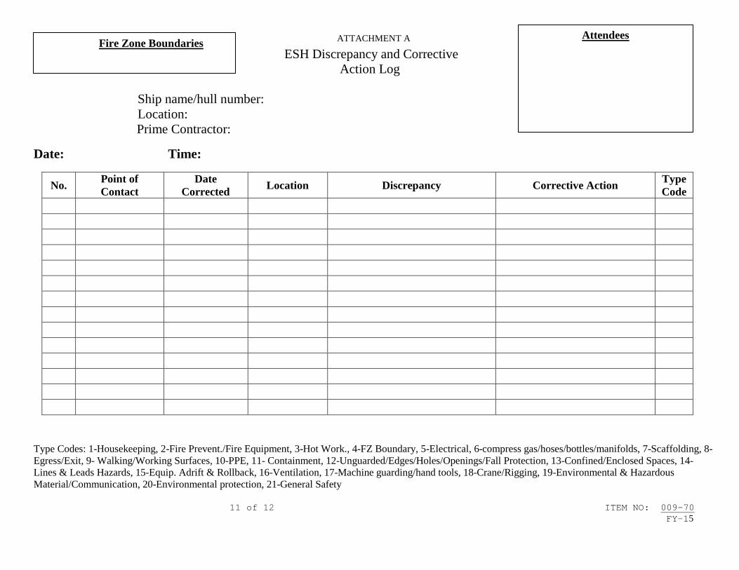
ATTACHMENT A
Type Codes: 1-Housekeeping, 2-Fire Prevent./Fire Equipment, 3-Hot Work., 4-FZ Boundary, 5-Electrical, 6-compress gas/hoses/bottles/manifolds, 7-Scaffolding, 8-Egress/Exit, 9- Walking/Working Surfaces, 10-PPE, 11- Containment, 12-Unguarded/Edges/Holes/Openings/Fall Protection, 13-Confined/Enclosed Spaces, 14-Lines & Leads Hazards, 15-Equip. Adrift & Rollback, 16-Ventilation, 17-Machine guarding/hand tools, 18-Crane/Rigging, 19-Environmental & Hazardous Material/Communication, 20-Environmental protection, 21-General Safety 11 of 12 ITEM NO: 009-70 FY-15
ESH Discrepancy and Corrective Action Log
Ship name/hull number:
Location: Prime Contractor:
Date: Time:
No. Point of Contact
Date Corrected Location Discrepancy Corrective Action Type
Code
Fire Zone Boundaries
Attendees

ATTACHMENT A
12 of 12 ITEM NO: 009-70 FY-15
ESH DISCREPANCY AND CORRECTIVE ACTION LOG INSTRUCTIONS
1- Fire Zone Boundaries: List the designated Fire Zone Boundaries. 2- Attendees: List Company and or Command and names of personnel present for walk thru. 3- Ship Name/hull Number: Indicate ship name and hull number of the location of the walk thru. 4- Location: Indicate location where ship is moored or docked, i.e. name of contractor facility or pier at Naval Base or Station. 5- Prime Contractor: Indicate prime contractor who has the contract with the SUPERVISOR. 6- Date: Indicate date of walk thru being accomplished. 7- Time: Indicate start time (24 hour clock) of walk thru being accomplished. 8- No. (number): List sequentially, each discrepancy noted during the walk thru. Number will continue where the numbering left off the previous day, until the end of the
availability. 9- Point of Contact: Indicate Company/Command identified with the discrepancy. 10- Date Corrected: Date condition was corrected. If condition is not corrected, condition will be carried over to the next walk thru until condition is corrected. 11- Location: Indicate location of the condition, i.e. space number or frame number. 12- Discrepancy: Indicate condition that needs corrective action, be specific as necessary. 13- Corrective Action: Indicate corrective action taken to correct the condition and who is responsible for the corrective action. 14- Code: Indicate code, located at the bottom of ATTACHMENT A that condition can be grouped with, i.e. lines on deck causing trip hazard would use code 14- Lines and
Leads Hazards.

1 of 3 ITEM NO: 009-71 FY-15
NAVSEA STANDARD ITEM FY-15 ITEM NO: 009-71 DATE: 17 JAN 2013 CATEGORY: II 1. SCOPE: 1.1 Title: Testing Requirements for Piping Systems; accomplish 2. REFERENCES: 2.1 S9086-RK-STM-010/CH-505, Piping Systems 2.2 S9086-RJ-STM-010/CH-504, Pressure, Temperature and Other Mechanical and Electromechanical Measuring Instruments 2.3 S9074-AR-GIB-010/278, Requirements for Fabrication Welding and
Inspection, and Casting Inspection and Repair for Machinery, Piping, and Pressure Vessels
2.4 T9074-AS-GIB-010/271, Requirements for Nondestructive Testing Methods 2.5 MIL-STD-2035, Nondestructive Testing Acceptance Criteria 3. REQUIREMENTS: 3.1 Accomplish testing of new and disturbed piping systems in accordance with 2.1. (V) "GAGE CHECK" 3.1.1 Each master and backup test gage shall conform to gage range and graduation shown on Table 504-6-1 of 2.2. The backup gage shall be cross-checked to the master hydrostatic test gage up to the maximum test pressure just prior to start of testing. Master and backup gages shall track within 2 percent of each other. 3.1.1.1 Each master and backup test gage used for vacuum testing shall consist of 2 compound gages with a 30 inch-0-30 PSI range. (I)(G) "LIQUID PENETRANT INSPECTION" or "MAGNETIC PARTICLE INSPECTION" 3.1.2 Accomplish liquid penetrant or magnetic particle test on root layer of all P-1 and/or P-LT welded joints in accordance with Paragraph
2 of 3 ITEM NO: 009-71 FY-15
505-11.1.2.6.a(1) of 2.1, and the requirements of 2.3 and 2.4. The accept or reject criteria shall be in accordance with Class One of 2.5. (See 4.2) (I)(G) "LIQUID PENETRANT INSPECTION" 3.1.3 Accomplish liquid penetrant tests on final layer of all P-1 and/or P-LT welded joints in accordance with Paragraph 505-11.1.2.6.a(1) of 2.1, and P-2 welded joints in accordance with Paragraph 505-11.1.2.6.a(2) of 2.1 for operating conditions greater than 200 degrees Fahrenheit or 200 PSIG, and the requirements of 2.3 and 2.4. The accept or reject criteria shall be in accordance with Class One of 2.5 for P-1 and/or P-LT, and Class 2 of 2.5 for P-2. (See 4.2) (V)(G) or (I)(G) "VISUAL INSPECTION - SHOP TEST" (See 4.3) 3.1.4 Accomplish a shop hydrostatic test of replacement piping, fittings, and components for evidence of external leakage and/or deformation. Allowable external leakage and/or deformation: None. (V)(G) or (I)(G) "VISUAL INSPECTION - HYDROSTATIC, LOW PRESSURE AIR, VACUUM, OR OPERATING PRESSURE TEST" (See 4.3) 3.1.5 Visually inspect the pressurized system or system under vacuum for evidence of external leakage and/or deformation. Allowable external leakage and/or deformation: None. 3.1.5.1 Joints requiring inspection shall remain uninsulated and unpainted until completion of successful inspection. 3.1.5.2 Provide a sketch of that portion of the system to be tested, showing the location of blanks, isolation valves, test connection, and the location of air vents to vent air. Sketch shall be on the test site during the accomplishment of the test. (I) "STATIC TEST" 3.2 Accomplish a static head pressure test of new and disturbed gravity drain piping (unpressurized piping), using clean, fresh water for a minimum of 30 minutes. Allowable leakage: None. (V)(G) "OPERATIONAL TEST" 3.3 Accomplish an operational test of new and disturbed gravity drain piping for proper operation and unobstructed flow. (V)(G) "OPERATIONAL TEST" 3.4 Accomplish an operational test of new and disturbed sounding tube piping by inserting a 16-inch theft sampler into sounding tube until it bottoms. Accomplish the test a minimum of 4 times for each sounding tube. There shall be no binding or sticking of sampler during this test.

3 of 3 ITEM NO: 009-71 FY-15
4. NOTES: 4.1 Boiler pressure vessel piping is defined as, "The piping from the pressure vessel drum or header up to the first valve off the pressure vessel drum or header." 4.2 Nondestructive testing requirements in 3.1.2 and 3.1.3 apply only when the operating pressure test option has been selected. 4.3 The paragraph referencing this note is considered an (I)(G) if the system is P-1, P-LT, or P-3a. If the system is P-2 or P-3b, then the paragraph is considered (V)(G). 4.4 Test pressure and test medium will be specified in invoking Work Item.


1 of 12 ITEM NO: 009-72 FY-15
NAVSEA STANDARD ITEM FY-15 ITEM NO: 009-72 DATE: 17 JAN 2013 CATEGORY: I 1. SCOPE: 1.1 Title: Physical Security at Private Contractor's Facility; accomplish 2. REFERENCES: 2.1 33 CFR Part 165, Regulated Navigation Areas and Limited Access Areas 2.2 33 CFR Part 334, Danger Zone and Restricted Area Regulations 3. REQUIREMENTS: 3.1 The requirements of 3.2.5, 3.2.6, 3.2.7, 3.2.8, and 3.2.9 are Force Protection measures the Contractor shall be able to meet under Force Protection Conditions Normal, Alpha, Bravo, Charlie, and Delta, respectively. The solicitation shall define the Force Protection Condition. Implementation of any other measures, when directed by the SUPERVISOR, will be the subject of an equitable adjustment. 3.2 Provide a written plan which shall be implemented for the protection of personnel, U.S. Naval vessels, work in process, the material and equipment to be installed therein, and GFM dry docks (as applicable) at the Contractor's facility, which addresses the requirements of this Standard Item. The written plan shall, as a minimum, be identified as "For Official Use Only (FOUO)". 3.2.1 Provide written designation to the SUPERVISOR of the individual who will be in charge of the security effort. 3.2.2 Attend security coordination meeting with Ship's Force and the SUPERVISOR to brief the Contractor's security plan and procedures prior to security conference of 3.2.3. 3.2.3 Conduct a security conference with federal, state, and local authorities, Ship's Force, and the SUPERVISOR within 45 calendar days prior to ship's arrival to ensure all parties are in agreement with the security procedures while the ship is in port. 3.2.4 Coordinate the establishment of the land and water areas adjacent to U.S. Naval vessels as restricted areas or limited waterway areas in accordance with 2.1 or 2.2, in cooperation with the Navy, U.S. Coast Guard, and Army Corps of Engineers.

2 of 12 ITEM NO: 009-72 FY-15
3.2.5 Under Force Protection Condition NORMAL, establish and maintain physical security boundaries, positive access controls, and other security measures to provide safeguards against hazards, including unauthorized entry, malicious mischief, theft, espionage, sabotage, and terrorism at Contractor's facility in accordance with Attachment A, to include the following: 3.2.5.1 Perimeter physical barriers 3.2.5.2 Perimeter openings control 3.2.5.3 Access and circulation control 3.2.5.4 Armed security force 3.2.5.5 Protective lighting 3.2.5.6 Signs and posting of boundaries 3.2.5.7 Security force communications 3.2.5.8 Random antiterrorism measures (RAM) 3.2.6 Under Force Protection Condition ALPHA, establish and maintain the following requirements in addition to 3.2.5: 3.2.6.1 Additional plant boundary protection 3.2.6.2 Assistance from state, local, and other law enforcement agencies 3.2.6.3 Increased personnel, property, and perimeter security checks 3.2.6.4 Increased security force manning commensurate with the additional actions directed under this section 3.2.6.5 Increased waterfront surveillance 3.2.6.6 Place vehicle barriers to reduce ease of vehicular access adjacent to the ship 3.2.6.7 Brief the security force and the SUPERVISOR concerning the threat, the security precautions being implemented, and what action is to be taken with respect to strangers, unidentified vehicles, abandoned parcels or suitcases, or unusual activity in or near the Contractor's facility. 3.2.6.8 Increase security spot-checks of vehicles, persons, and buildings near U.S. Naval vessels.
3 of 12 ITEM NO: 009-72 FY-15
3.2.6.9 Limit access points for vehicles and personnel commensurate with performance of the Job Order. 3.2.6.10 Inspect 100 percent of commercial vehicles entering the controlled industrial area and/or piers. 3.2.6.11 Test procedures for mass notification. 3.2.6.12 Review requirements related to implementing additional security actions in the event of an increased threat. 3.2.6.13 Review barrier plans. 3.2.7 Under Force Protection Condition BRAVO, establish and maintain the following requirements in addition to 3.2.5 through 3.2.6: 3.2.7.1 Request the Captain of the Port or U.S. Coast Guard District Commander to activate the Naval Vessel Protection Zones in accordance with 2.1. 3.2.7.2 Establish communications with state, local, and other law enforcement, fire, and emergency management agencies. 3.2.7.3 At the beginning of each workday, as well as at random intervals, inspect the interior and exterior of buildings in regular use for suspicious packages. Secure and regularly inspect buildings, rooms, and storage areas not in regular use for unusual conditions or suspicious activity. 3.2.7.4 Clear the area within 100 feet (30.5 meters) of U.S. Naval vessels of all non-mission-essential materials and vehicles as determined by the SUPERVISOR. 3.2.7.5 Review requirements related to implementing additional security actions in the event of an increasing threat. 3.2.7.6 Identify paths for critical materials to maintain production. 3.2.7.7 Brief all employees working at the facility, including the ship's crew and subcontractor employees, concerning the threat, the security precautions being implemented and what action is to be taken with respect to strangers, unidentified vehicles, abandoned parcels, containers or suitcases, and any other suspicious or unusual activity. 3.2.7.8 Increase security presence and surveillance, and randomly inspect vehicles, persons and accompanying items entering the facility.

4 of 12 ITEM NO: 009-72 FY-15
3.2.7.9 Review mail and material screening procedures at the facility. 3.2.8 Under Force Protection Condition CHARLIE, establish and maintain the following requirements in addition to 3.2.5 through 3.2.7: 3.2.8.1 Inspect the interior and exterior of buildings in regular use for suspicious activity or objects at frequent intervals. 3.2.8.2 Increase protection for crew berthing to reduce vulnerability. 3.2.8.3 List work that would be required to permit safe relocation of the vessel and its crew to the nearest Government facility as designated by the SUPERVISOR. 3.2.8.4 Determine work that will be stopped if the next higher Force Protection Condition is implemented. Determine a list of and inform mission-essential personnel, including Contractor work force. Communicate critical Work Items to the SUPERVISOR, ship's Commanding Officer, and/or Shipyard Commander. 3.2.8.5 Increase surveillance in and around waterside perimeter and facilities. Position floats, work boats, and barges along the sides of the U.S. Naval vessel and any occupied berthing barges to create a buffer zone. 3.2.8.6 Limit access points to strictly enforce entry control. Inspect all vehicles entering the controlled industrial area and/or pier. Review access procedures to ensure no unauthorized personnel gain access into the facility. 3.2.9 Under Force Protection Condition DELTA, establish and maintain the following requirements in addition to 3.2.5 through 3.2.8: 3.2.9.1 Immediately notify state and local law enforcement agencies and the U.S. Coast Guard of any knowledge of terrorist activity, suspicious persons or criminal activity. 3.2.9.2 Limit access points to the absolute minimum. 3.2.9.3 Strictly control all facility access points, ensure positive identification of all personnel, and search all vehicles and their contents, suitcases, briefcases, and packages entering the Contractor's facility. 3.2.9.4 Accomplish continuous security patrols of all areas of the facility, to include the waterfront, occupied by U.S. Naval vessels and personnel.

5 of 12 ITEM NO: 009-72 FY-15
3.2.9.5 Prepare U.S. Naval vessels for movement away from the Contractor's facility when directed by the SUPERVISOR. 3.2.9.6 Discontinue work except that directly related to the integrity of the vessel and as otherwise directed by the SUPERVISOR. 3.2.9.7 Implement the plan to deny access to individuals not essential or critical to the overall mission of protecting and/or moving vital Navy assets onto the facility and occupied buildings. 3.3 Submit one legible copy, in approved transferrable media, of the plan to the SUPERVISOR for review and approval no later than 15 days prior to availability start date. 3.3.1 Accomplish the requirements of the approved plan. 3.3.2 Any changes at the Contractor's facility affecting physical security or the approved plan shall be submitted to the SUPERVISOR for approval within 24 hours. 3.4 Provide procedures for coordinating the Contractor's security efforts with those of the SUPERVISOR and the Commanding Officer's designated representative. 3.5 Prepare an itemized statement of cost incurred for the work covered by this Standard Item. Submit one legible copy, in approved transferrable media, of the statement to the SUPERVISOR within 30 days of delivery or redelivery (as applicable) of the ship. The statement shall itemize the total direct labor hours with the applicable direct labor rates, overhead, General and Administrative (G&A) and/or other indirect rates, material, material handling charges, subcontractor costs, Other Direct Costs (ODC), and freight costs (as applicable). Where final overhead rates are not available, use the most current billing rate(s). 3.5.1 The Government may perform an audit of the Contractor's statement of cost incurred. The Contractor, upon request, shall make available to the SUPERVISOR all records, related correspondence, and the substantiating data upon which the statement of cost incurred is based. 4. NOTES: 4.1 U.S. Naval vessel means any vessel owned, operated, chartered, or leased by the U.S. Navy; any pre-commissioned vessel under construction for the U.S. Navy, once launched into the water; and any vessel under the operational control of the U.S. Navy or a Combatant Command. 4.2 Controlled Industrial Area (CIA) means an area of the shipyard in which construction, conversion, repair, or overhaul of U.S. Navy vessels is conducted.

6 of 12 ITEM NO: 009-72 FY-15
4.3 USFF AT OPORD 3300 (series) provides general security requirements for Fleet Activities. The SUPERVISOR will use this reference as a guide in applying force protection measures appropriate to the unique situation at each Contractor’s facility. 4.4 A vehicle is defined as a means of transportation that transports people or objects.

7 of 12 ITEM NO: 009-72 FY-15
ATTACHMENT A OTHER SECURITY MEASURES
1. Perimeter Physical Barriers: a. Physical barriers, including both natural (e.g., mountains, swamps,
thick vegetation, rivers, bays, cliffs) and structural (e.g., fences, walls, doors, gates, vehicle barriers) which control, delay, impede, and discourage access by unauthorized persons. To be effective, such barriers shall be augmented by armed security force personnel or other means of protection and assessment.
b. Physical barriers shall be employed along Contractor facility
perimeters. The barrier or combination of barriers used shall afford an equal degree of continuous protection along the entire perimeter.
c. Structural barriers such as fences or walls shall be a minimum of 8
feet in height, and any uncontrolled opening shall be securable to afford protection against unauthorized entry.
d. The waterfront security required to protect the Navy asset is
dependent on the asset. e. Closed Circuit Television (CCTV) installs will be planned for
installation by using Chapter 4 of the Unified Facilities Criteria (UFC) 4-021-02NF. Plans will be submitted to the SUPERVISOR for approval, prior to installation. This UFC document provides guidance on how to design electronic security systems required by the current antiterrorism/force-protection environment.
f. The patent number for the original Port Security Barrier (PSB) is
6,681,709 B1. The patent number for the Port Security Barrier –T variant (PSB-T) is 7,401,565 B2. There is no separate patent for the Port Security Barrier –V variant (PSB-V). At the time of publishing SI 009-72 FY-12 (CH-2), Harbor Offshore Barriers (5720 Nicolle St., Ventura, CA 93003) and Truston Technologies, Inc. (520 Ridgely Ave., Annapolis, MD 21401) were both licensed to manufacture the original PSB, as well as both the T and V variant.
Asset Security measures
For Patrol Coastal (PC), MSC Strategic Sealift Ship (SSS) (reduced operational status)
- Adjacent landside security (patrols,
surveillance, pier access control) no special requirements in waterways.
- Identify restricted area waterways with buoys and signs.

8 of 12 ITEM NO: 009-72 FY-15
Asset Security measures
Surface combatants, Amphibious ships (full operational status), auxiliary, MSCSSS, ammunition ships, mine warfare
The requirements above and - Security Zone per 3.2.4 - Use of a Port Security Barrier (PSB-V or -T model
dependent on expected geographic and environmental conditions as determined by the SUPERVISOR) per 1.d above, or other physical barrier approved by the numbered Fleet commander.
- In areas where the cognizant SUPERVISOR agrees
the use of waterborne barrier(s) is not in the best interest of the US Navy, a dedicated waterborne security boat shall patrol within 200 yards of the protected vessel equipped with a bullhorn, night vision device, spotlight, marine flares, lethal and non-lethal weapons, and a two-way communications device according to the specifications described in Addendum 1.
**Note: If PSB-V or –T or SUPERVISOR authorized
(numbered Fleet commander-approved) physical barrier is in place, a dedicated waterborne security asset is not required.
Carriers, submarines (see next row for SSBN)
The requirements above and - Electronic water/waterside security system to
include, but not limited to, closed-circuit television for the purposes of surface craft detection.
- Use water barriers to prevent direct unchallenged access from small boat attacks.
SSBN
The requirements above and - Per SECNAVINST S8126.1 - Use water barriers to stop small boat threat
2. Perimeter Openings: Openings in the perimeter barrier shall be kept to
the minimum necessary for the safe and efficient operation of the Contractor facility. Access through such openings shall be controlled, or the openings shall be secured.
3. Access and Circulation Control: d. A system of personnel and vehicle movement control is required at
Contractor facilities. The degree of control shall be in keeping with efficient operations yet afford defense-in-depth to provide graduated levels of protection.

9 of 12 ITEM NO: 009-72 FY-15
e. Armed or unarmed sentries may be assigned to check identification at pedestrian and vehicle entry control points to restrict and control movement by vehicles and unauthorized personnel from gaining access into the facility.
f. The facility shall coordinate with the local postal and courier
services in developing a plan for ensuring that all mail and courier delivered packages to the facility are properly screened by the delivery service prior to being delivered to the contractor facility's mailroom.
4. Armed Security Force: The Contractor security force shall consist of
designated persons specifically organized, trained, armed, and equipped to provide physical security.
5. Protective Lighting: g. Protective lighting, to include work lighting, increases the
effectiveness of security forces and has considerable deterrent value.
h. Contractors shall provide adequate illumination to discourage or
detect attempts to enter facilities and reveal the presence of unauthorized persons within such areas.
i. Lighting shall support security force activities such as
identification of badges and personnel at perimeter openings, surveillance of facility perimeter/avenues of approach, and inspection of unusual or suspicious circumstances.
6. Signs and Posting of Boundaries: j. Trespass laws applicable to the jurisdiction in which the facility is
located will govern signs and posting of perimeter boundaries at Contractor facilities.
k. Size, placement, and use of any language in addition to English
should be appropriate for the stated purpose. Signs will read essentially as follows:
WARNING RESTRICTED AREA KEEP OUT Authorized Personnel Only l. Signs shall be posted at regularly-used points of entry and at
intervals along the facility perimeter such that any reasonable person would conclude that everyone crossing the boundary into the facility would have been informed of the above.

10 of 12 ITEM NO: 009-72 FY-15
7. Security Force Communications: a. The activity security force requires sufficient equipment to maintain
continuous, secure 2-way voice communications between elements (fixed/mobile posts, and supervisory personnel) of the security force and U.S. Naval vessel's watch section. Establish communications between the Contractor's security force and the U.S. Naval vessel's watch section.
b. The facility shall maintain a communication system for use in
emergencies or crisis situations to facilitate effective two-way voice communications among state and local law enforcement agencies and the U.S. Coast Guard.
c. The facility shall establish a communication system, pre-recorded
and/or live-voice, but capable of broadcasting information to all building occupants or personnel in the immediate vicinity during or prior to an emergency or crisis situation.
8. Random Antiterrorism Measures (RAM): As a deterrent, randomly apply the
measures from higher Force Protection Conditions and other RAM including: m. Keep personnel involved in implementing increased security
requirements on call. n. Inspect deliveries to protect against the introduction of
unauthorized material. o. Cars and other non-mission essential items shall be moved 100 feet
from U.S. Naval Vessels and buildings where the crew is located or work is in progress.
p. Inspect mail for letter or parcel bombs. q. On entry of visitors to the facility, physically inspect them and
accompanying items. r. Search vehicles entering the facility. s. Erect barriers and obstacles to provide additional traffic controls
to areas where U.S. Naval Vessels and crews are located. t. Consult local authorities about closing public roads and facilities
that might make sites more vulnerable. u. Other site-specific RAM that shall be incorporated into the
Contractor's physical security plan and/or company-specific implementation procedures.

11 of 12 ITEM NO: 009-72 FY-15
Addendum One to Attachment A of Standard Item 009-72
Waterborne Security Boats
Mission The boats are primarily used to provide a dedicated waterborne presence and deterrence in the immediate vicinity of no more than three (3) U.S. Naval Assets. The word ”dedicated” is defined as on-site, 24-hours a day, 7 days a week, and responsive solely to the operational confines of the protected asset(s). Normally, a single waterborne security boat will be designated for each U.S. Naval Asset. Waterborne security boats must be capable of conducting continuous patrols in the immediate vicinity of the protected asset(s), or continuous monitoring of a patrol zone when assigned to protect clustered U.S. Naval Assets (a patrol zone shall not exceed 200 yards and shall not include more than 3 protected assets). Waterborne security boats will be used to provide restricted area enforcement by providing a layered defense and deterrence mechanism. This includes the ability for early detection of intruders under day/night, and all-weather conditions. Projected Operating Environment The projected operating environment of the waterborne security boats will normally be in protected harbors or inland waterways. These boats will be expected to operate in varying temperatures depending on the climate at the location the boat(s) will be used. Temperatures can be expected to vary from below 32 degrees Fahrenheit to above 100 degrees Fahrenheit. Storm conditions and warnings often issued in the operating environment include: small craft, gale, storm, and hurricane warnings. General Characteristics There are no specific hull material requirements for waterborne security boats. Waterborne security boats must be visible from distances of at least 500 yards to the unaided eye, during periods of unrestricted visibility and must possess all safety equipment required by federal and local regulations. Waterborne security boats must also display a placard on both sides of the vessel with the word "Security" of sufficient size and reflective composition to be visible from 500 yards to the unaided eye, during periods of unrestricted visibility (250 yards during periods of low-light) and in accordance with federal and local regulations. These boats must possess a hailing mechanism capable of warning/hailing approaching craft at 500 yards. Hailing capability may consist of modified human voice (e.g., through the use of a bull horn, PA system, etc.), or mechanical (e.g., siren, pulsating tone, etc.). The boat must have a weather resistant spot/flood light capable of rotating 360 degrees with instant start/restart and at least 6,000,000 candlepower.

12 of 12 ITEM NO: 009-72 FY-15
The boat must have a fully operable marine band radio (VHF). Length range: 27 feet to 40 feet And why: This size is necessary for safety and mission accomplishment, ease of discernment, crew accommodation, visual deterrent, and ease of maneuverability when responding to contacts of interest during all-weather patrols. Breadth 8 feet 6 inches And why: The minimum breadth of 8 feet 6 inches is necessary to provide a stable platform, crew accommodation, visual deterrent, ease of maneuverability, safety and mission accomplishment when responding to contacts of interest during all-weather patrols. Maximum Draft: 4.5 feet The maximum draft of 4.5 feet is necessary for ease of maneuverability in and around the protected assets. Number of Crew: Two. At least one coxswain and one observer/lookout shall be assigned to each boat for the duration of the patrol period. These personnel shall be qualified in the operation of the security boat, and shall be qualified with, and armed with personal protective weapons in accordance with SECNAVINST 5500.29C, DoDD 5210.56, and relevant state and local regulations. Required Cargo Capacity or Deck Space: Stowage space must be sufficient to accommodate at least four (including 2 spare) life vests, a flood light, a first-aid kit, a back board, and specialized tactical equipment, etc. Propulsion System (e.g., Diesel inboard with outdrive, Diesel inboard with waterjet, or gasoline outboard) and why: The propulsion system must be able to conduct multiple idle/sprint missions during each patrol period. Because of the limited operating area, propulsion systems must be capable of rapidly responding to a contact of interest (normally within the 200 yard operating zone) and rapidly reversing. Speed 20kts. A minimum speed of 20kts is necessary to provide the capability to rapidly respond to contacts of interest or rapidly move out of the line of fire from shipboard responders in the event of a deadly engagement.

1 of 14 ITEM NO: 009-73 FY-15
NAVSEA STANDARD ITEM FY-15 ITEM NO: 009-73 DATE: 07 NOV 2013 CATEGORY: I 1. SCOPE: 1.1 Title: Shipboard Electrical/Electronic/Fiber Optic Cable; remove,
relocate, repair, and install 2. REFERENCES: 2.1 Standard Items 2.2 MIL-STD-2003, Electric Plant Installation Standard Methods for
Surface Ships and Submarines 2.3 MIL-STD-2042, Fiber Optic Cable Topology Installation Standard
Methods for Naval Ships 2.4 S9300-A6-GYD-010, Electrical Workmanship Inspection Guide for Surface
Ships and Submarines 2.5 SE000-01-IMB-010, Navy Installation and Maintenance Book (NIMB),
Section IX, Installation Standards (Source CD: N0002400003) 2.6 MIL-STD-1310, Shipboard Bonding, Grounding, and Other Techniques for
Electromagnetic Compatibility and Safety 2.7 SE000-01-IMB-010, Navy Installation and Maintenance Book (NIMB),
Section VII, Industrial Electromagnetic Compatibility (IEMC) Work Process Instructions (Source CD: N0002400003)
2.8 IA PUB-5239/31, Information Assurance Shipboard Red/Black
Installation Publication 2.9 NSTISSAM TEMPEST/2-95, Red/Black Installation Guidance (FOUO) 3. REQUIREMENTS: 3.1 Identify, isolate and remove each cable designated for removal or replacement by the individual Work Items. 3.1.1 Remove each cable in its entirety.
2 of 14 ITEM NO: 009-73 FY-15
3.1.1.1 Blank each bulkhead, deck penetration, and multi-cable transit device from which cable was removed and which will not be reused, in accordance with Part 3 of 2.2 and Part 3 of 2.3. 3.1.1.2 Blank each hole not required to be used in equipment from which cable was removed. 3.1.1.3 Remove unused hangers from which cable was removed and which will not be reused, and grind areas flush in way of removals. 3.1.1.4 Install new banding for cableways affected by cable removals, in accordance with Part 4 of 2.2 and Part 4 of 2.3. 3.2 Identify and isolate each cable to be pulled back, rerouted, relocated, or reused to support work required by the individual Work Items. 3.2.1 Inspect each cable end to be disconnected for correct conductor identification sleeving, including size, type, and legible lettering in accordance with referenced drawings. Ensure lugs are secured to leads and are of correct size and type, and the insulation is not damaged. Ensure optical connectors are secured to the cable, the correct type, and the cable jacket is not damaged. Accept and reject criteria for lugs and sleeving for non-fiber optic cables shall be in accordance with Chapters 3 and 4 of 2.4. 3.2.1.1 Submit one legible copy, in approved transferrable media, of a report listing results of the requirements of 3.2.1 to the SUPERVISOR. 3.2.2 Disconnect each cable. Record and retain electrical and optical hook-up data. 3.2.2.1 Accomplish the requirements of 009-22 of 2.1 for disconnected non-fiber optic cables. 3.2.2.2 Accomplish the requirements of Method 6D1 of Part 6 of 2.3 for fiber optic cable. 3.2.3 Remove each cable from equipment and pull back to predetermined locations. Coil each cable and secure to prevent damage. 3.2.3.1 Protect disconnected connectors and wiring from the environment. 3.2.4 Install each cable to equipment or component in accordance with 2.2 and 2.5 for non-fiber optic cable, and 2.3 for fiber optic cable. 3.2.5 Band disturbed cable in accordance with Part 4 of 2.2 for non-fiber optic cable, and Part 4 of 2.3 for fiber optic cable. 3.2.6 Bond and ground non-fiber optic cable in accordance with 2.6.

3 of 14 ITEM NO: 009-73 FY-15
3.2.7 Accomplish the requirements of 009-22 of 2.1 for non-fiber optic cables upon completion of banding and prior to reconnecting. 3.2.8 Accomplish the requirements of Method 6D1 of Part 6 of 2.3 for fiber optic cables upon completion of banding and prior to reconnection. 3.2.9 Prepare each cable end and serve the lead bundles in accordance with 2.2 and 2.5 for non-fiber optic cable and 2.3 for fiber optic cable. 3.2.10 Connect each cable, using referenced drawings or retained hook-up data. 3.2.11 Install new cable identification tags in accordance with 2.2 and Part 4 of 2.3, using 2.5 for guidance. 3.3 Isolate and splice non-fiber optic cables in accordance with Part One, Appendix E of 2.2, to support work required by the individual Work Items. Fiber optic cables shall only be spliced in accordance with Paragraph 4.3 of 2.3, and MIL-PRF-24623/4. 3.3.1 Accomplish the requirements of 009-22 of 2.1 for each spliced non-fiber optic cable. 3.3.2 Accomplish the requirements of 3.2.5 through 3.2.11. 3.4 Isolate and repair non-fiber optic cables in accordance with Part One, Appendix A through D of 2.2, and fiber optic cable in accordance with Part One of 2.3, to support work required by the individual Work Items. 3.4.1 Accomplish the requirements of 009-22 of 2.1 for each non-fiber optic cable. 3.4.2 Accomplish the requirements of Method 6D1 of Part 6 of 2.3 for each fiber optic cable. 3.4.3 Accomplish the requirements of 3.2.5 through 3.2.11. 3.5 Install each new cable, cableway, penetration, lug, and connector in accordance with 2.2, 2.5, and 2.6 for non-fiber optic cable and 2.3 for fiber optic cable, and referenced drawings, to support work required by the individual Work Items. 3.5.1 New cable shall conform to MIL-DTL-24643 (low smoke), and MIL-DTL-24640 (lightweight) in lieu of MIL-DTL-915. New Radio Frequency (RF) cables shall conform to MIL-DTL-17 (Rev) low smoke. New fiber optic cable shall conform to MIL-PRF-85045. 3.5.1.1 Preserve the cable data package provided with new fiber optic cable. Retain the original cable data package with the unused portion of the cable.

4 of 14 ITEM NO: 009-73 FY-15
3.5.1.2 Submit one legible copy, in approved transferrable media, of a report containing copies of the cable data packages obtained in 3.5.1.1 and cable number listings of the cables taken from each reel to the SUPERVISOR. 3.5.2 Accomplish a visual and continuity test of each fiber optic cable in accordance with Method 6A1 and Method 6D1 of 2.3. 3.5.2.1 Maintain a copy of a report listing results of the requirements of 3.5.2 for reference by the SUPERVISOR. 3.5.3 Use existing cableways and penetrations wherever possible. Penetrations shall be correct size in accordance with 2.2 and 2.3. 3.5.4 For hard-wired cables, install new conductor identification sleeving conforming to SAE-AMS-DTL-23053, Class One, white, marked with indelible ink. 3.5.4.1 Mark in accordance with the referenced drawings and/or equipment technical manual. 3.5.4.2 Install new lugs of correct size and shape conforming to MIL-T-16366 or SAE-AS7928. Do not cut off strands of copper to reduce size of lead to fit lug. Use correct barrel and hole size. 3.5.4.3 Install new fiber optic connectors of the correct size and type conforming to MIL-C-83522 or MIL-PRF-28876. 3.5.5 Accomplish the requirements of 009-22 of 2.1 upon completion of lugging, connector attachment, and banding of non-fiber optic cables. 3.5.6 Accomplish the requirements of Method 6C1 of Part 6 of 2.3 upon the completion of connector attachment, slack management, and banding for fiber optic cables. 3.5.6.1 Submit one legible copy, in approved transferrable media, of a report listing results of the requirements of 3.5.6 to the SUPERVISOR, using Attachment A. 3.5.7 Connect leads to terminal boards and connectors to equipment using referenced drawings. 3.6 Weatherproof and seal connectors exposed to the weather in accordance with 2.7. 3.7 Submit a written procedure to the SUPERVISOR for review and approval prior to the initiation of production work for the installation of multi-pin, coaxial, and fiber optic connectors, using 2.2, 2.3, and 2.5 for the minimum requirements.

5 of 14 ITEM NO: 009-73 FY-15
3.7.1 This procedure only requires a one-time submittal/approval unless the Standard Items change and/or references change or are updated, and shall contain the following minimum information: 3.7.2 Reference the appropriate fabrication document for which the procedure is applicable. 3.7.3 Qualification requirements for the personnel performing the work. 3.7.4 Inspection and documentation forms. 3.7.5 Acceptance and rejection criteria. 3.8 Provide written designation of the Qualified Persons who will prepare electrical/fiber optic cable endings to receive connectors, assemble connector parts on the cable endings, and attach the connectors to the cable endings. Provide written designation of the Qualified Person or Persons who will supervise and inspect the execution of the process. 3.8.1 Submit one legible copy, in approved transferrable media, of any additions or modifications to the SUPERVISOR prior to the start or continuation of work. 3.8.2 Maintain current copies of the credentials of the Qualified Persons for reference by the SUPERVISOR. 3.8.2.1 Submit one legible copy, in approved transferrable media, of specific documents when requested by the SUPERVISOR. 3.9 Inspect existing cable installations affected as a result of work required by the individual Work Items and interferences within the first 25 percent of contract completion. Ensure that cable installations are in accordance with 2.2, and 2.3 for fiber optic cable. 3.9.1 Submit one legible copy, in hard copy or approved transferrable media, of a report of cable installation conditions not in compliance with 2.2 and 2.3 to the SUPERVISOR, using Attachments B and C, within 72 hours of completion of inspections. 3.9.1.1 Report shall state if cable installation inspections resulted in no compliance issues. 3.10 Install new fasteners conforming to MIL-DTL-1222, Type One, Grade 316, stainless steel, for areas exposed to weather and high moisture areas, and Type One, Grade 2 or 5, carbon steel, zinc plated, for other areas to support work required by the individual Work Items. 3.11 Remove, install, and relocate cables which are part of the secure electrical information processing systems or are located within a secure

6 of 14 ITEM NO: 009-73 FY-15
processing space in accordance with 2.8 and 2.9 to support work required by the individual Work Items. 3.12 After installation of cables, accomplish the requirements of 009-25 of 2.1 for the local air hose test of each new and disturbed multi-cable transit device, multi-cable penetrators, stuffing tubes, kick pipes, and cable penetrations of tightness boundaries. 3.12.1 Accomplish a light test in accordance with Part 3, Appendix B of 2.2 as an alternative for non-structural assemblies of multi-cable transit devices. 3.13 Accomplish the requirements of 009-32 of 2.1 for new and disturbed surfaces. 4. NOTES: 4.1 A new circuit is defined as a cable not previously installed. 4.2 Pulled-back cables are those which are disconnected and physically removed from a wireway, conduit, or cableway to protect the cable from industrial work. 4.3 Reused cables are those cables disconnected from the equipment to facilitate equipment removal. 4.4 Electrical connector fabrication is the preparation of cable endings to receive multi-pin connectors, coaxial connectors, fiber optic connectors, assembly of connector parts on cables, and securing connectors to cables. 4.5 A Qualified Person is defined as a person who has successfully completed connector fabrication training and meets the qualification requirements stated below. 4.5.1 Emphasizes the importance of connector fabrication to the performance and long-term reliability of shipboard combat systems. 4.5.2 Uses 2.2 through 2.5 for basic instructional material supplemented by connector manufacturer's instructional material as desired. 4.5.3 Requires classroom lecture, study, and demonstration of each topic in Appendix A of Part 5 of 2.2, and 2.3. 4.5.4 Requires individual student practice in the use of specified tools and performance of connector fabrication techniques and procedures described in Appendices B through H of Part 5 of 2.2, Parts One through 6 of 2.3, and Paragraph 2-20.2 of 2.5. 4.5.5 Requires a minimum of 32 hours of combined classroom lecture and laboratory practice in the type of connectors to be fabricated, either electrical/electronic or fiber optic.

7 of 14 ITEM NO: 009-73 FY-15
4.6 Connector fabrication qualifications consist of: 4.6.1 Connector Fabricator Qualification requirement: Successful completion of the training course required in 4.5.5 plus successful completion of 40 hours on-the-job training under the tutelage of a qualified connector fabricator or a qualified connector fabrication supervisor in the type of connectors to be fabricated, either electrical/electronic or fiber optic. 4.6.2 Connector Fabrication Supervisor Qualification requirement: Successful completion of the classroom training required in 4.5.5 plus be the incumbent of a supervisory electrical or electronic mechanic position. 4.6.3 Connector Fabrication Quality Assurance Inspector Qualification requirement: Successful completion of the classroom training required in 4.5.5 plus be the incumbent of a quality assurance specialist or inspector position. 4.7 Cable installations consist of cable, banding, equipment, penetrations, cableways, cable separation and connection(s), and associated hardware. 4.8 Attachment C is provided as an aid to completion of Electrical Cableway Inspection Form Attachment B. 4.9 Attachment D is provided as an aid to accomplishing required documentation of electrical/electronic disconnect/reconnect reporting requirements.

8 of 14 ITEM NO: 009-73 FY-14 (CH-1)
ATTACHMENT A
OPTICAL MEASUREMENT RECORD
DATE HULL NUMBER
INSPECTED BY CODE INSPECTING ORGANIZATION TELEPHONE
ENDPOINT LOCATIONS OR EQUIPMENT NAME: SOURCE DETECTOR
INSTALLATION/CONFIGURATION DRAWING CABLE SERIAL NUMBER
CABLE TYPE1 REFRACTIVE INDEX OF FIBER2 ATTENTUATION/KM3 @1300 NM @850 NM
CONNECTOR TYPE(S)1 TEST EQUIPMENT MANUFACTURER/MODEL NO.
SERIAL NO. CALIBRATION DUE DATE SOURCE WAVELENGTH(S)(NM) /
SOURCE CABLE NO.4
DETECTOR CABLE NO.4
1300NM/850NM WINDOW (CIRCLE ONE)
FIBER COLOR5 OR NUMBER
FIBER COLOR5 OR NUMBER
ACCEPTABLE LOSS (dB)
FORWARD REFERENCE POWER
FORWARD MEASURED POWER
FORWARD LOSS (dB)
FORWARD RETURN LOSS (dB)
REVERSE REFERENCE POWER
REVERSE MEASURED POWER
REVERSE LOSS (dB)
REVERSE RETURN LOSS (dB)
CABLE/LINK LENGTH (M)
NOTES: 1RECORD MIL-SPEC NUMBER IF APPLICABLE. 4FOR LINK MEASUREMENTS ONLY. 2RECORD VALUE FROM CABLE REEL DATA SHEET, IF UNAVAILABLE DEFAULT TO 1.490. 5STANDARD COLORS: BLUE, ORANGE, GREEN, BROWN, SLATE, WHITE, 3RECORD VALUES FROM CABLE REEL DATA SHEET. RED, BLACK, YELLOW, VIOLET, PINK, TAN CONNECTOR END FACE QUALITY: CONNECTION LIST: REMARKS: SIGNATURE:

9 of 14 ITEM NO: 009-73 FY-14 (CH-1)
ATTACHMENT B
ELECTRICAL CABLEWAY INSPECTION FORM
DATE HULL NUMBER INSPECTED BY INSPECTING ORGANIZATION
SER # COMPT DECK FRAME P/S POS CABLE CIRCUIT DESIG
CABLE TYPE *CAT *NAVSEA DWG NO.
EQUIPMENT
DESCRIPTION
DESCRIPTION
DESCRIPTION
DESCRIPTION
* SEE ATTACHMENT C FOR "CATEGORY" GUIDANCE

10 of 14 ITEM NO: 009-73 FY-14 (CH-1)
ATTACHMENT C
INSPECTION CRITERIA FOR ELECTRICAL CABLES AND CABLEWAYS CATEGORY 1 - Immediate Hazard CATEGORY 2 - Potential Hazard CATEGORY 3 - Non-Hazardous
ITEM CRITERIA CATEGORY
I. CABLES
A. Installation
1. Minimum bend radius exceeded, causing visual damage to cable. 1
2. Minimum bend radius exceeded; No visual cable damage, cable rings out and meggers satisfactorily.
3
3.
Equipment connector supporting weight of cable (more than 32 inches of cable from last support to end use equipment). (18 inches from shock mounted motors).
1
4. Cables run on or near hot objects (steam or exhaust pipes, griddles, ovens, etc. 1
5. Cable run outside of hangers. 3
6. Lack of slack at expansion joints. 2
7. Excess slack between hangers. (Minimum distance of 6 feet 4 inches between deck and cables.)
3
8. Excess cable slack stored in wireway. 3
B. Damaged
1. Bulging, bubbling or discoloration of cable jacket (evidence of overloading, overheating or hot spots.)
1
2. Bulging, bubbling or discolored cable jacket; but cable rings out and meggers satisfactorily.
2
3. Cable chafed or cut through outer jacket only. 2
4. Cable chafed or cut through, inner wire insulation damage. 1
5. Cable pulled out of equipment/junction box penetrations and leads exposed 1
6. Armored and unarmored cables in contact at an oblique angle causing chafing of unarmored jacket.
2
7. Fiber cable chafed or cut beyond the cable outer jacket to the Kevlar strength members 1
C. Dead-ended

11 of 14 ITEM NO: 009-73 FY-14 (CH-1)
ITEM CRITERIA CATEGORY
1. Cable dead-ended, not end sealed and labeled (serialized) properly at both ends. 1
2. Cable for future use not properly sealed on both ends and labeled at both ends for the specific use.
1
3. Cable dead-ended, end sealed and labeled (serialized) properly. 3
D. Spliced
1. Improper materials/methods used for splicing, or evidence of loose joints. 1
2. Splice located in bend of cable. 2
II. BANDING
A. All Cable Runs
1. Banding cuts cable outer jacket (banding too tight). 1
2. Banding compressing outer jacket (banding too tight but not cutting jacket). 3
3. Plastic tie wraps used in place of banding straps (metal banding strap required). 2
4. Cables secured to hanger with bailing wire or rope. 1
5. Bands cut and left in wireway. 2
6. Channel rubber not installed where required. 2
B. Horizontal Cable Runs
1. Banding not installed at breakout hangers before and after penetrations or at change of direction of wireway.
2
C. Vertical Cable Runs
1. No banding or loose banding (banding required on every hanger). 2
III.
A. Cableways
1. Cable hangers or hardware cutting into the cable jacket. 1
2.
Improper hanger spacing (Cable hangers are required at least every 32 inches except that hangers for multiple tier overhead aluminum decks shall be spaced every 16 inches).
2
3. Inadequate cableway support (hangers, hardware, tiers, or cable straps missing) or welds cracked.
2

12 of 14 ITEM NO: 009-73 FY-14 (CH-1)
ITEM CRITERIA CATEGORY
4. Overload/Overcrowded cable hangers. 3
5. Maximum no. of tiers exceeded. 3
6. Inadequate fastener length. 3
7. One-half inch clearance between cable run and hangers above or structure not provided. 2
IV. EQUIPMENT
A. Covers
1. Junction box or equipment covers loose or missing. 1
B. Mounting
1. Cable supporting the weight of equipment (power junction boxes, lighting fixtures switch boxes, etc.)
1
2. Missing loose or improperly installed mounting hardware on equipment. 2
C. Cable Entrance
1. Watertight penetrators not utilized for entrance to watertight equipment enclosures. 1
2. Drip loops, drip shields plastic sealer or bottom penetration not utilized for entrance to non-watertight drip proof equipment.
1
3. Cable can be moved in and out of tube. Improperly packed or not packed. 1
4. Nylon tube base loose in enclosure. (O-ring missing) 1
V. DECK/BULKHEAD PENETRATION
A. Non-watertight Deck or Bulkhead Cable Penetration
1. No plastic sealer around cables through collars where required. 1
2. Chafing protection not installed at non-watertight deck or bulkhead cableway penetrations.
2
3. Chafing ring overloaded. 3
4. Inadequate chafing protection and damage evidence. 1
B. Watertight Deck or Bulkhead Cable Penetration
1.
No plastic sealer around cable at stuffing tubes which are exposed to the weather. Note: If plastic sealer is installed at locations other than those exposed to the weather, it is not required to be removed.
2

13 of 14 ITEM NO: 009-73 FY-14 (CH-1)
ITEM CRITERIA CATEGORY
2. Stuffing tube or kickpipe not utilized (cable installed without tube). 1
3. Unused stuffing tube or kickpipe not plugged. 1
4. Stuffing tube or kickpipe assembly incomplete (missing gland nut, packing, or pipe connector).
1
5. Stuffing tube assembly incorrect (improper packing). 2
6. Stuffing tube or kickpipe too large for size of cable. 3
7. Multiple cables in a single stuffing tube or kickpipe. 2
8.
Stuffing tube or kickpipe damaged to point where complete assembly not possible (cracked welds, damaged threads, out-of-round, etc.) if firestop material is installed.
2
C. Watertight Deck or Bulkhead Penetrations Utilizing Multiple Cable Penetration
1. Insert blocks, compression bolts or filler blocks missing. 1
2. Improper size blocks used for size cable installed violating watertight integrity. 2
3. Incorrect type of RTV used to seal armored cable through MCP blocks. 1
4. RISE type MCP not properly sealed. 1

14 of 14ITEM NO: 009-73
FY-15
DATE: HULL NUMBER: JOB ORDER: WORK ORDER:WORK ITEM NO: TITLE:NAMEPLATE DATA:MANUFACTURER: VOLT: AMPS:HZ: HP: CAT#: ID#:
Calibrated Inst #:
Disconnect Reconnect Term Lug Insulation Sleeving
* Report Cable Length for Defective Cables Only.
Date:Date:
Remarks:
Cable Length *
ATTACHMENT D
SHIPBOARD ELECTRIC CABLE: DISCONNECT & RECONNECT
CABLE TYPE CIRCUIT ID CONDUCTOR ID
LEAD COLOR
CABLE END TERM PT
Disconnected by: _____________________________________Reconnected by: _____________________________________
Cable ConditionContinuity
Megger ReadingsCABLE START TERM PT

1 of 9 ITEM NO: 009-74 FY-15
NAVSEA STANDARD ITEM FY-15 ITEM NO: 009-74 DATE: 17 JAN 2013 CATEGORY: I 1. SCOPE: 1.1 Title: Occupational, Safety and Health Requirements; accomplish 2. REFERENCES: 2.1 29 CFR Part 1915, Occupational Safety and Health Standards for
Shipyard Employment 2.2 Safe Work Practices for Marine Hanging Staging: An OSHA Guidance
Document, April 2005 2.3 Joint Fleet Maintenance Manual (JFMM) 2.4 S0400-AD-URM-010/TUM, Tag-Out Users Manual 2.5 S9086-KC-STM-010/CH-300, Electric Plant – General 2.6 29 CFR Part 1904.7, Recording and Reporting Occupational Injuries
and Illness, General Recording Criteria 3. REQUIREMENTS: 3.1 Establish, document, implement, and maintain a written Safety Plan appropriate for the work to be accomplished. Provide a copy of the Safety Plan to the SUPERVISOR upon request. At a minimum, the Safety Plan shall include the following elements: 3.1.1 Method(s) of communicating potential hazards, prior to the start of any task, to contractor’s employees. 3.1.1.1 Hazards to be addressed shall include but not be limited to emergency evacuation and muster policy, confined space, and energy control. 3.1.2 Method(s) of communicating potential hazards, prior to the start of any task, to subcontractors and other potentially affected personnel.

2 of 9 ITEM NO: 009-74 FY-15
3.1.2.1 Hazards to be addressed shall include but not be limited to emergency evacuation and muster policy, confined space, and energy control. 3.1.3 A process for performing a Job Safety Analysis/Job Hazard Analysis (JSA/JHA) for: 3.1.3.1 Processes and equipment new to the worksite. 3.1.3.2 Existing processes and equipment that have been involved in mishaps or near misses. 3.1.3.3 Maintain a copy of each JSA/JHA which shall be available for review by the SUPERVISOR upon request. 3.1.4 A process for identification, communication, abatement, and prevention of unsafe conditions and work practices. 3.1.5 Method(s) to account for employees and subcontractors working in isolated areas, e.g. Confined spaces. 3.1.6 Method(s) to ensure work areas and walkways are adequately illuminated. 3.1.7 Method(s) to establish and maintain good housekeeping practices. 3.1.8 Method(s) to ensure that medical services and first aid are readily accessible. 3.1.9 Method(s) to provide adequate and readily accessible sanitation facilities. 3.1.10 A process for notifying the Quarterdeck and initiating emergency response. 3.2 Update the Safety Plan as circumstances warrant or at the request of the SUPERVISOR. 3.3 Provide a Safety Point of Contact to the SUPERVISOR before each project. 3.4 Provide appropriate Personal Protective Equipment (PPE) for employees and monitor utilization in accordance with 2.1. 3.5 Mark or tag material and equipment brought aboard naval facilities and vessels. Marking or tags must endure the repair process, and must stay attached and/or be readable until the material or equipment is removed.

3 of 9 ITEM NO: 009-74 FY-15
3.5.1 Marking/tags shall be a company unique identifier or display the company name, point of contact, phone number, item description and contents. 3.6 Provide the SUPERVISOR a complete list of subcontractors (e.g., company name) hired by the contractor prior to subcontractor(s) commencing work aboard naval facilities or vessels. 3.6.1 Contractor shall monitor, inspect, oversee, and abate hazardous or deficient conditions related to the conduct and work practices of subcontractor(s). 3.7 Ensure Material Handling Equipment (MHE) and Aerial Work Platforms (AWP) are operated and maintained in accordance with 2.1 and manufacturer's specifications. 3.7.1 Ensure operators of MHE and AWP meet applicable training and licensing requirements and provide documentation to the SUPERVISOR upon request. 3.7.2 Ensure operators conduct a daily operational check of the MHE or AWP before use. 3.7.2.1 Maintain copies of the daily operational checks for the duration of the performance period of the prime contract and provide copies to the SUPERVISOR upon request. 3.8 “Screw type” hose clamps are prohibited on any pressurized hose (e.g., compressed gas and air hoses). 3.9 Temporary lights shall have 3-conductor cable, guard or shield, hook, and lamp holder. Exposed non-current-carrying metal parts of the fixture shall be grounded either through a third wire in the cable containing the current conductors, or through a separate wire that is grounded at the fixture's voltage source. 3.10 Rigging of temporary services, such as but not limited to hoses, electrical lines, welding leads, and temporary lights shall be kept clear of the decks on temporary trees or brackets and be arranged to minimize tripping and other safety hazards and to allow free access through doors, hatches, and passageways. 3.10.1 Temporary service lines shall be routed to allow emergency access and egress to all areas of the ship and shall not impede damage control and watchstander performance of duties. Where appropriate, run temporary services outboard to keep passageways clear. 3.10.2 Secure temporary services with metal hangers or heat and flame resistant line. Plastic tie wraps, string, rope or other combustible material shall not be used.

4 of 9 ITEM NO: 009-74 FY-15
3.10.3 Remove temporary services from the ship when no longer needed. 3.10.4 Evaluate temporary services during the daily fire prevention and housekeeping inspection made jointly with the SUPERVISOR and Ship’s Force. Discrepancies shall be promptly corrected. 3.11 Each employee shall have a flashlight or other adequate light source onboard a navy vessel. 3.12 Notify personnel of lifting operations by audible alerts during crane operations (e.g., whistles or horns). Audible alerts shall be utilized throughout the lifting evolution. 3.13 Comply with the fall protection requirements of 2.1. 3.14 Scaffolding shall be built and maintained in accordance with 2.1 and manufacturer's specifications or under the direction of a Professional Engineer. 3.14.1 Provide manufacturer's specifications to the SUPERVISOR upon request. 3.14.2 Tag all scaffolding. Tags must endure the repair process, and must stay attached and be readable. 3.14.2.1 Tags shall display the stage of completion, scaffold load capacity, and availability for use. 3.14.3 Erect scaffolding so that a swing gate is installed at each working level accessed by a ladder. 3.14.4 Ensure marine hanging scaffolding meets the guidance provided in 2.2. 3.14.5 When there is a danger of tools, materials, or equipment falling from a scaffold and striking employees below during the erection, dismantling, or altering of scaffolding, the area below the scaffold to which objects can fall shall be barricaded and adequately identified with signs and danger tape. Employees not involved with the scaffolding operation shall not be permitted to enter the hazard area. 3.15 Ensure protective measures are taken in accordance with 2.1 before creating a deck opening or an unguarded edge. 3.15.1 Deck openings and unguarded edges shall not be left unprotected for any amount of time.

5 of 9 ITEM NO: 009-74 FY-15
3.16 Crimping or pinching of fuel gas/oxygen/compressed gas hoses, air hoses, or hoses carrying hazardous/toxic/flammable materials is prohibited. All hoses shall be disconnected at the manufacturer’s fittings. Prior to disconnecting hoses from equipment/tool, pressure shall be released by disconnecting the hose from the source, e.g., manifold or gas cylinder. 3.17 Notify the SUPERVISOR and accomplish the requirements of 2.1, Volume IV, Chapter 10 of 2.3, and 2.4 prior to working aloft. 3.17.1 Accomplish the requirements of the vessel’s work aloft instruction and utilize the vessel’s working aloft request form. 3.17.1.1 The vessel’s working aloft request form shall be routed to the OOD/CDO for permission for working over the side or aloft. Do not go aloft on masts, stacks, or kingposts or be suspended over the side by a crane without first obtaining written permission from the OOD in the form of a working aloft request form. 3.17.1.2 Verify that the working aloft request form is active prior to going aloft each time. 3.17.2 Provide and use personal fall arrest system (PFAS), working lanyard, and climber safety device when going aloft where a climber safety rail is installed. If a climber safety rail is not installed, use a double lanyard configuration. 3.17.3 In the absence of a properly guarded work platform, position a safety observer on deck near the work being performed. The safety observer shall keep the deck area beneath the work aloft free of unnecessary personnel. 3.17.4 In case of an emergency, the safety observer shall notify the Quarterdeck or emergency services. 3.18 Accomplish safety precautions as specified in 2.5 for work on electrical/electronic circuits and equipment. 3.18.1 Obtain written authorization from the ship’s Commanding Officer before testing or entering components which are energized at a value greater than 30 volts.
3.19 Notify the SUPERVISOR and vessel’s Quarterdeck immediately by verbal means of each accident, injury, fire, flooding, and electrical shock occurring on the vessel, dry dock or pier/berth involving contractor/subcontractor personnel. 3.19.1 Secure the accident/fire and electrical shock site and preserve the scene until released by the SUPERVISOR.

6 of 9 ITEM NO: 009-74 FY-15
3.19.2 Submit one legible copy, in approved transferrable media, of a formal written report, Attachment A, of the event to the SUPERVISOR within 24 hours of each accident requiring medical treatment, shock, and each fire. Provide daily updates within 24 hours upon request by the SUPERVISOR, until the final report is submitted. The written report shall contain the name of each injured person, date and time of incident/fire, extent of each personal injury or property damage, contractor/subcontractor name, Job Order/Work Item Number, type of incident/fire, location of event (ship name and hull number, space, compartment), a brief description of the event including occurrences leading up to the incident/fire, equipment involved, Contract Number, witness and/or individuals involved, short term and long term corrective action, and root cause analysis. 3.20 Repair and maintenance employees working aboard vessels, dry docks and piers shall have a valid 10 hour OSHA Maritime Shipyard Employment Course #7615 or NAVSEA-approved equivalent completion card within 60 days of employment. 3.20.1 The authorized maritime trainer shall have successfully completed the OSHA 5400 trainer course in occupational safety and health standards for the maritime industry. The authorized maritime trainer shall have a current OSHA Training Institute ID number and shall follow the OSHA outreach training program guidelines. 3.20.2 Maintain current copies of the training documents required by the guidelines for reference by the SUPERVISOR. Submit one legible copy in approved transferrable media when requested by the SUPERVISOR. 4. NOTES: 4.1 The term “medical treatment” is defined in 2.6. 4.2 Requests for deviations/waivers of training requirements will only be approved by NAVSEA and on a case-by-case basis. This includes equivalent training for foreign nationals. 4.3 Contractors may provide the OSHA outreach training program report as documentation of completing Course #7615 until completion cards are received. 4.4 The term “repair and maintenance employee” is defined as one whose employment relates to or is in conjunction with ship repairing, shipbuilding, or shipbreaking work, including, but not restricted to, inspection, testing, and employment as a fire watch. This excludes employees who provide incidental services that do not influence shipyard employment such as delivery services.

ATTACHMENT A FOR OFFICIAL USE ONLY
7 of 9 ITEM NO: 009-74 FY-15
0BINCIDENT REPORT Report #
INITIAL REPORT
REQUESTED UPDATE
FINAL REPORT
TYPE OF INCIDENT: NAME(S) OF INJURED (if applicable): INCIDENT DATE: TIME:
COMPANY: SUPERVISOR: LOCATION OF INCIDENT:
TYPE OF INJURY OR FIRE:
CAUSE OF INCIDENT:
EQUIPMENT INVOLVED:
WORK ITEM NUMBER:
CONTRACT NUMBER:
WITNESS AND/OR INDIVIDUALS INVOLVED NAME(S) DEPT. COMPANY
DESCRIPTION OF INCIDENT
DISPOSITION OF INJURED (if applicable)
IMMEDIATE CORRECTIVE ACTION
INVESTIGATED BY (NAME):
TITLE:
SIGNATURE OF INVESTIGATOR: DATE:
1BINCIDENT REPORT Report #

ATTACHMENT A FOR OFFICIAL USE ONLY
8 of 9 ITEM NO: 009-74 FY-15
LONG TERM CORRECTIVE ACTION
ROOT CAUSE ANALYSIS
INVESTIGATED BY (NAME):
TITLE:
SIGNATURE OF INVESTIGATOR: DATE:

ATTACHMENT A FOR OFFICIAL USE ONLY
9 of 9 ITEM NO: 009-74 FY-15
Incident Report Instructions
REPORT NUMBER- Unique tracking number created by contractor TYPE OF INCIDENT- Injury, fire or near miss NAME(S) OF INJURED- Self Explanatory INCIDENT DATE: - Self Explanatory
TIME: - Self Explanatory COMPANY: - Prime and subcontractors involved SUPERVISOR – Supervisor of employee(s) involved LOCATION OF INCIDENT: - Base/Yard, Ship name and hull number, space number and compartment name TYPE OF INJURY OR FIRE – i.e. broken arm, laceration to head or Class A, B, C fires, smoldering CAUSE OF INJURY – i.e. Equipment failure, PPE, process EQUIPMENT INVOLVED – Equipment working on and equipment being used to cause incident WORK ITEM NUMBER – Work Item being accomplished when incident occurred CONTRACT NUMBER: - Contract Number assigned by government agency i.e. RMC, Alteration Installation Team (AIT) Sponsor. WITNESS AND/OR INDIVIDUALS INVOLVED – Name, company of witnesses and or individuals involved with the incident. DESCRIPTON OF INCIDENT OR NEAR MISS – Short description of events leading up to incident and extent of injuries and or damage to equipment. DISPOSITION OF INJURED – i.e. Transported to hospital via ambulance or POV, transported to clinic, released from hospital, name of hospital or clinic, limited duty or loss time (if known). IMMEDIATE CORRECTIVE ACTION – i.e. Scene/space secured, ship notified (who and when), RMC notified (who and when) clean up of blood, equipment secured fire debris cleaned up. INVESTIGATED BY – Self Explanatory. TITLE – Self Explanatory. SIGNATURE OF INVESTIGATOR – Self Explanatory. DATE – Self Explanatory. LONG TERM CORRECTIVE ACTION – What action(s) were taken so that incident does not reoccur, i.e. training, safety stand down or process/policy change. ROOT CAUSE ANALYSIS – Process by which you will identify the cause or contributing factors of the incident. Note: Attach additional information as necessary.


1 of 5 ITEM NO: 009-75 FY-15
NAVSEA STANDARD ITEM FY-15 ITEM NO: 009-75 DATE: 29 JUL 2011 CATEGORY: II 1. SCOPE: 1.1 Title: Circuit Breaker; repair 2. REFERENCES: 2.1 Equipment Technical Manual 3. REQUIREMENTS: 3.1 Disconnect electrically and mechanically and remove each circuit breaker, using 2.1 for guidance. 3.1.1 Matchmark and retain mounting hardware and fasteners. 3.1.2 Protect exposed terminal connections and internal switchboard parts from dirt and damage. 3.1.2.1 Each phase shall be isolated and protected from other phases. 3.2 Disassemble each circuit breaker, using 2.1 for guidance. 3.2.1 Inspect and test electrical and mechanical components, assemblies, subassemblies, internal circuitry, and hardware to design characteristics and determine missing and defective components, circuitry, and hardware in accordance with 2.1. 3.2.1.1 Acceptance criteria for silver contacts is that wear shall be less than 50 percent of original thickness after dressing, contacts shall have no evidence of copper migration, and shall have no irregular, burnt, or pitted interface after dressing. 3.2.1.2 Acceptance criteria for non-silver contacts is that, after dressing, wear shall be less than 10 percent of original thickness and contacts shall have no irregular, burnt, or pitted interface after dressing. 3.2.2 Test internal wiring, coils, and transformers for open and short circuits and 500 volt megger insulation resistance to ground. Record readings. Minimum acceptable resistance to ground shall be one megohm.

2 of 5 ITEM NO: 009-75 FY-15
3.2.3 Submit one legible copy, in approved transferrable media, of a report listing results of the requirements of 3.2.1 and 3.2.2 to the SUPERVISOR. 3.3 Remove defective and install new electrical and mechanical components, assemblies, subassemblies, internal circuitry, and hardware. Install new electrical and mechanical components, assemblies, subassemblies, internal circuitry, and hardware where missing. New material shall conform to the requirements of 2.1 and shall be obtained from the Federal Stock System or the Original Equipment Manufacturer (OEM), except for non-restricted parts. 3.3.1 Clean each component free of dirt, lubricants, and other foreign matter. 3.3.1.1 Steam cleaning of circuit breakers is not authorized. 3.3.2 Resilver previously silver plated contacts in accordance with ASTM B 700. 3.3.3 Dress, burnish, adjust, and align arcing and main contacts (contacts that experience arcing in functional duty) in accordance with 2.1. 3.3.4 Replace existing cadmium-plated parts with zinc in accordance with ASTM A 153. 3.3.5 Dip and bake taped insulated coils and open transformers in varnish conforming to MIL-I-24092, Class 155. 3.3.5.1 Dip and bake insulated coils and open transformers in Dolph Varnish 1105, Epoxylite Esterlite 605, or Schenectady International Isolite 862M varnish in localities where MIL-I-24092 varnish does not meet state and local air pollution control district standards. 3.3.6 Remove existing and install new coil and transformer leads in place of those found to be missing or defective. 3.3.7 Repair defective connections. 3.3.8 Free-up and adjust moving parts and latching mechanisms. 3.3.9 Lubricate the current-carrying parts (except for interrupting contacts) and sliding joints with lubricant conforming to MIL-L-87177, Type I, Grade B. Lubricate mechanical pivots, excluding latch roller face components, with high performance multi-purpose grease conforming to DOD-G-24508. 3.3.9.1 Apply new lubricant sparingly and wipe off excess. 3.3.10 Test and inspect molded and insulation parts in accordance with the following criteria:
3 of 5 ITEM NO: 009-75 FY-15
3.3.10.1 Phase-to-phase dielectric strength 2,000 volts minimum. 3.3.10.2 Surface burn marks and hairline cracks are acceptable but shall not deteriorate the mold surface or impair physical strength. Cracks are not permitted in wall section between phase and a ground plane when there is a conducting part in contact with the wall section. Cracks should not exceed 0.75 inch in length, and in no case should be greater than 50 percent of the length of the surface in which the crack appears. 3.3.10.3 Surface cracks should not exceed 1.5 inches in length, and in no case should be greater than 50 percent of the length of the surface in which the crack appears. 3.3.10.4 Submit one legible copy, in approved transferrable media, of a report listing results of the requirements of 3.3.10 to the SUPERVISOR. (V) "SHOP TEST" 3.4 Shop test and inspect each motor operator and motor in accordance with 2.1. 3.4.1 Submit one legible copy, approved transferrable media, of a report to the SUPERVISOR listing defects. (V) "SETTINGS AND MILLIVOLT DROP TEST" 3.5 Reassemble each circuit breaker and accomplish adjustments and settings in accordance with 2.1. 3.5.1 Align and true each set of stationary and movable contacts to the manufacturer's specifications. 3.5.2 Accomplish millivolt drop test to each set of contacts in accordance with 2.1 or Original Equipment Manufacturer (OEM) requirements. (V) "TEST, CALIBRATION, AND ADJUSTMENT" 3.6 Test, calibrate, adjust, and certify the trip units of each circuit breaker for time delay and instantaneous trip settings in accordance with 2.1. 3.6.1 Accomplish a heat run test for repaired type ACB and AQB circuit breakers. 3.6.1.1 Connect each ACB type circuit breaker to a test set and apply rated current to each individual phase of the circuit breaker for 30 minutes. After 5 minutes, measure the voltage across the line to load contacts of each pole and calculate the contact impedance. Satisfactory impedance for 1,600-4,000 ampere ACB's is below 225 microhms, and below 1,050 microhms for 600-900 ampere ACB's.

4 of 5 ITEM NO: 009-75 FY-15
3.6.1.2 Connect each AQB-type molded case circuit breaker to a test set and apply rated current to each phase simultaneously for one hour. The AQB shall not trip within that hour. 3.6.2 Submit one legible copy, in hard copy or approved transferrable media, of a report listing results of the requirements of 3.6.1 to the SUPERVISOR. 3.6.3 Attach a calibration label to the face of each circuit breaker denoting the name and location of the calibration facility and date of calibration. In the event there is insufficient room on the face of the circuit breaker, attach the calibration label to the right hand side of the breaker as viewed from the front. 3.7 Install and connect each circuit breaker. 3.7.1 Install new threaded fasteners, washers, and lockwashers to replace those found to be missing or defective. (V)(G) "OPERATIONAL TEST" 3.8 Accomplish final adjustments and test operate each circuit breaker, including control and safety devices. 3.8.1 Close and trip each circuit breaker electrically from local and remote stations. Four consecutive successful times required. 3.8.1.1 Ensure generator heater interlock is de-energized by the generator circuit breaker. 3.8.2 Repeat the requirements of 3.8.1 manually. 4. NOTES: 4.1 Equipment technical manual will be listed in the invoking Work Item. 4.2 Repair and overhaul will be accomplished by the Navy Designated Overhaul Point (DOP) at Puget Sound Naval Shipyard, the OEM, or a commercial repair facility that has demonstrated to the SUPERVISOR the capability to perform the work. Capability to perform circuit breaker overhaul and repair work includes having the facilities, trained mechanics, and access to the OEM`s qualified parts and repair procedures. Use of non-qualified restricted parts violates the integrity of the circuit breaker, nullifying the breakers prior qualification under the QPL process. Restricted parts must be obtained from the OEM either directly or via (if available) the Federal stock system. If a restricted part is replaced with an unqualified part, the qualification of the particular circuit breaker is revoked until the full set of QPL required tests are repeated and submitted to NAVSEA for approval.

5 of 5 ITEM NO: 009-75 FY-15
4.3 Non-restricted parts are defined as nuts, bolts, screws, washers, lockwashers, cotter pins, O-rings, indicator lights, and indicator light globes (colored and clear) only. 4.4 The following ACB circuit breakers listed by manufacturer contain non-friable asbestos arc chutes: 4.4.1 SPD, ITE, ITE/Gould: 640R, 900RC, 901R, 1600R, 1600HR, 1600HRC, 2000HR, 2000RC (450V), 2601R, 2801R, 3200HR, 4000HR. 4.4.2 General Electric: all types. 4.4.3 Westinghouse: All DBN types.


1 of 2 ITEM NO: 009-76 FY-15
NAVSEA STANDARD ITEM FY-15 ITEM NO: 009-76 DATE: 29 JUL 2011 CATEGORY: II 1. SCOPE: 1.1 Title: Waveguide and Transmission Line Temporary Lay-Up,
Pressurization, and Purging; accomplish 2. REFERENCES: 2.1 Equipment Technical Manual 2.2 SE000-01-IMB-010, Navy Installation and Maintenance Book (NIMB),
Section IX, Installation Standards (Source CD: N0002400003) 3. REQUIREMENTS: 3.1 Disconnect each dry air pressure line at last mechanical joint prior to connection to ship's dry air panel, using 2.1 for guidance. 3.2 Accomplish uninterrupted nitrogen or dry air lay-up for waveguides and rigid coaxial cables in accordance with Paragraph 5-2.7 of 2.2 and lay-up procedures of 2.1. 3.2.1 Do not connect unregulated pressurized air to equipment sub-assemblies or components. Ensure that temporary dry air pressure source(s) are connected in accordance with lay-up procedures of 2.1 to prevent equipment damage due to over-pressurization. No pressurization shall be supplied to waveguide in excess of the normal operating pressures specified for that equipment. 3.2.2 Ensure temporary dry air meets the requirements of Paragraph 5-1.14 and 5-1.15 of 2.2, and the following: 3.2.2.1 Dew Point: Minus 40 degrees Fahrenheit at 80 PSIG. 3.2.2.2 Quality of Air: Filtered to remove all particulate matter greater than one micrometer and filtered for a total amount of contamination (including oil contaminants) not to exceed one part per million by weight. 3.2.3 Pressurize each line as specified in the lay-up procedures of 2.1.

2 of 2 ITEM NO: 009-76 FY-15
3.2.3.1 Where specific lay-up instructions are not available, pressurize those lines to 3 PSIG. 3.2.3.2 Install relief valve downstream of temporary source, setting relief pressure at 5 PSIG. 3.2.4 Identify leaks in accordance with Paragraph 5-2.7.2 and 5-2.7.3 of 2.2. 3.2.4.1 Submit one legible copy, in approved transferrable media, of a report listing results of the requirements of 3.2.4 to the SUPERVISOR. 3.3 Remove temporary pressurization when directed by the SUPERVISOR. 3.3.1 Connect the dry air pressure line disconnected in 3.1. 3.3.2 Purge and pressurize in accordance with Paragraph 5-2.7 of 2.2. 4. NOTES: 4.1 Equipment technical manual will be listed in the invoking Work Item. 4.2 Where lay-up conditions permit, ensure equipment's dry air control/monitor panels are operational for continuous monitoring of temporary dry air in the equipment space(s).

1 of 16 ITEM NO: 009-77 FY-15
NAVSEA STANDARD ITEM FY-15 ITEM NO: 009-77 DATE: 17 JAN 2013 CATEGORY: I 1. SCOPE: 1.1 Title: Cofferdam Requirements; accomplish
2. REFERENCES: 2.1 Standard Items 2.2 S0600-AA-PRO-160/CH-16, Underwater Ship Husbandry Manual, Cofferdams 3. REQUIREMENTS: 3.1 Maintain watertight integrity to a level 4 feet above the maximum anticipated draft, including but not limited to the following operations: access openings, hull plating replacement, welding to the hull when pre-heating is required, modifications or repairs to damage or deterioration that will degrade watertight integrity or stability, or piping and mechanical repairs that are expected to result in less than double-valve protection. 3.2 Accomplish the requirements of 009-09 of 2.1 for the installation of each cofferdam (plug, patch, dry chamber, and stern tube seal) in accordance with 2.2, including the following: 3.2.1 Include the Operational Checklist, Table 16-9 of 2.2, in the Process Control Procedure (PCP). 3.2.2 Prior to the start of the PCP, any time the installed cofferdam will serve as the only barrier to the sea (single valve protection), ensure Ship's Commanding Officer sign-off via the SUPERVISOR, as required by Paragraph 16-4.7.1.4 (plugs), or Paragraph 16-5.2.10 (patches), or Paragraph 16-6.6 (dry chambers), or Paragraph 16-7.6.5 (stern tube seals) of 2.2. 3.2.2.1 The first page of the PCP shall be stamped SINGLE VALVE PROTECTION, at the top, in minimum one-half inch letters. 3.2.2.2 Attachment A shall be used to document single valve isolation signatures. 3.3 Submit one legible copy, in approved transferrable media, of the design and maintenance records in accordance with Paragraph 16-5.2.7

2 of 16 ITEM NO: 009-77 FY-15
(patches), or Paragraph 16-6.6.4 (dry chambers), or Paragraph 16-7.6.3 (stern tube seals) of 2.2 to the SUPERVISOR. 3.4 Prior to the start of the PCP, submit one legible copy, in approved transferrable media, of Ship's Force notification in accordance with Paragraph 16-4.7.1.3 (plugs), or Paragraph 16-5.2.9 (patches), or Paragraph 16-6.6 (dry chambers), or Paragraphs 16-7.6.5 and 16-7.6.8 (stern tube seals) of 2.2 to the SUPERVISOR. (I)(G) “REMOVAL OF COFFERDAM” 3.5 Prior to the removal of the cofferdam, submit one legible copy, in approved transferrable media, of Ship’s Force notification in accordance with Paragraph 16-4.7.1.3 (plugs), or Paragraph 16-5.2.9 (patches), or Paragraph 16-6.6 (dry chambers), or Paragraphs 16-7.6.5 and 16.7.6.8 (stern tube seals) of 2.2 to the SUPERVISOR. 3.5.1 Remove each cofferdam (plug, patch, dry chamber, or stern tube seal) and all associated components upon completion of repairs. 4. NOTES: 4.1 2.2 and associated forms are available at: http://www.supsalv.org/manuals/uwsh/chap16/chap16.pdf 4.2 Attachment B is provided as an aid to cofferdam PCP development.

3 of 16 ITEM NO: 009-77 FY-15
ATTACHMENT A
AUTHORIZATION FOR SINGLE VALVE ISOLATION
Date____________________
Subj: PROVIDE NOTIFICATION OF SINGLE VALVE ISOLATION REQUIREMENT AND PROVIDE PRECAUTIONARY PROCEDURES TO BE EMPLOYED DURING REPAIRS/ALTERATIONS TO SEA-CONNECTED SYSTEMS.
Ref: (a) OPNAVINST 3120.32 Series 1. The procedures involved in this repair/alteration will subject the affected area to a flooding hazard during the
time the repair is being accomplished. The purpose of this notification is to outline the responsibilities for precautionary measures placed upon the contractor and the ship while the repairs/alterations are in progress.
2. System: The repairs/alterations to be accomplished to the following system:
______________________________________Component/Space _______________________________ 3. Prior to Commencing work, the contractor shall provide:
a. A procedure, in accordance with the requirements of NAVSEA Standard Item 009-77, has been developed and approved by the SUPERVISOR (Copy Attached).
b. The sequence of repairs to be accomplished, including drawings of the system and valve locations. The proposed system isolation must be discussed and mutually agreed upon between the ship, SUPERVISOR, and the contractor.
c. Identify possible hazards of single valve isolation failure. ___________________________________ d. Expected start ______________ and completion _______________ for single valve isolation evolution. e. Watertight boundaries have been defined, sighted, tagged out and verified. ______________________
4. During the period of this repair, the following minimum precautions are required:
a. Ship’s Supervisor, E-7 or above, must be present to verify single valve isolation and breaking of pressure boundary.
b. Ship’s Force will provide a watch on the affected system and monitor for leaks, etc.
c. Ship will maintain appropriate state of damage control readiness. 5. See attached drawing of system and valve locations. ______________________________ ________________________ _________________________ Ship’s SRA Coordinator Engineering Officer Commanding Officer/approval ______________________________ Ship Repair Officer (SRO)/Project Management Officer (PMO) (Notification made to Waterfront Operations Officer)
(Held on site for SBS Review)

ATTACHMENT B COFFERDAM PCP REVIEW GUIDE Minimum Requirements and Critical Factors
4 of 16 ITEM NO: 009-77 FY-15
References
1. NAVSEA STD ITEM 009-01, General Criteria; accomplish 2. NAVSEA STD ITEM 009-09, Process Control Procedure (PCP); provide and accomplish 3. S0600-AA-PRO-160 Underwater Ship Husbandry Manual, Chapter 16 (Appendix C, D, E, F, G; Table 16-9) 4. NAVSEA STD ITEM 009-77, Cofferdam Requirements 5. NAVSEA STD ITEM 009-24, Authorization, Control, Isolation, Blanking and Tagging Requirements;
accomplish 6. MIL-STD-777, Schedule of Piping, Valves, Fittings, and Associated Piping Components for Naval Surface
Ships or 802-5959353, MIL-STD-777 Modified for DDG-51 Class 7. NAVSEA STD ITEM 009-04, Quality Management System; provide
All cofferdam PCPs shall include the following MINIMUM criteria, including Critical Factors1, as appropriate, preferably in the order shown below (for further elaboration, see the applicable Reference):
Criteria Ref Justification YES NO N/A
1. ADMINISTRATIVE CONTROLS.
1.1. SHIP’S NAME 1 3.2.4.1
1.2. SHIP’S HULL NUMBER 1 3.2.4.1
NUCLEAR VESSEL?
1.3. CONTRACTOR’S NAME 2 2
3.1.1 Attachment A
1.4. CONTRACTOR’S ADDRESS 2 2
3.1.1 Attachment A
1.5. WORK ITEM AND PARAGRAPH 2 1
Attachment A 3.2.4.1
1.6. PCP TITLE 2 2
3.1.2 Attachment A
1.7. PCP NUMBER (WITH REVISION) 2 2
3.1.2 Attachment A
1.8. DATE OF PCP DEVELOPMENT 2 2
3.1.2 Attachment A
1.9. PCP SUBMISSION DATE 2 2 1
3.1.10 Attachment A 3.2.4.4
1.10. TITLE OF CONTRACTOR’S REPRESENTATIVE. The individual responsible for creating the PCP.
2 1
3.1.10 3.2.4.4
1.11. APPROVAL SIGNATURE 2 2
3.1.10 Attachment A

ATTACHMENT B COFFERDAM PCP REVIEW GUIDE Minimum Requirements and Critical Factors
5 of 16 ITEM NO: 009-77 FY-15
2. PURPOSE/SCOPE. Describe the process and: (a) Type of cofferdam (b) Affected hull opening (c) Affected equipment/system(s)
2 2 3
3.1.3 Attachment A Appendix C
3. PERSONNEL QUALIFICATIONS. 2 2 3
3.1.4 Attachment A 16-10.2.3
3.1. Diver Training Plan. Note the Diving Contractor‘s Training Plan & documentation complies with Reference 3, 16-10.2.1 & 10.2.2.
3 3 3 3 3
16-10.2.1 16-10.2.2 16-10.2.4.1 16-10.2.4.2 16-10.2.4.3
3.2. Diver Competency. Note the Divers: (a) Are ADCI recognized with 7 years (min.) commercial
diving experience; (b) Have current medical physical screening; (c) Have current CPR and First Aid certification; (d) Have cofferdam program qualification; (e) Have performed six (6) cofferdam installations; (f) Have performed a cofferdam installation within the past six
(6) months.
3 3 3 3 3
16-1.6 16-10.2.3.3.1 16-10.2.3.3.2 16-10.2.4.2.5 16-10.2.4.2.8
3.2.1. Minimum Diver Cofferdam Training Requirements. Require the completion of Reference 3, Appendix E demonstrating Diver fundamental cofferdam knowledge.
3 3 3 3
16-5.2.20 16-10.2.2 16-10.2.3.3.4.(c) Appendix E
3.3. Engineering. Specify NON-standard cofferdam(s)2 were designed by a degreed Engineer or Professional Engineer.
3 3
16-3.11 16-10.2.3.1
3.4. Fabrication Personnel. Note Contractor Welders are qualified to Company’s approved welding procedure.
3 3
16-10.2.3.2 16-10.2.4.3
4. SAFETY GUIDELINES.
CF 4.1. Personnel Protective Gear. Note that the minimum required PPE will be used and provide several examples. 2 Attachment A
4.2. Hazardous Materials. Note Hazardous Material Identification and minimization methods comply with NAVSEA STD ITEM 009-03, Toxic and Hazardous Substances; control, as required.
2 2
3.1.9 Attachment A

ATTACHMENT B COFFERDAM PCP REVIEW GUIDE Minimum Requirements and Critical Factors
6 of 16 ITEM NO: 009-77 FY-15
4.3. Emergency Flooding Plan. Whenever single-valve protection is in place, include in the written notification to the ship a specific plan for immediate installation of a replacement piping component or internal sealing blank. Provide a note indicating that S/F is responsible for developing an on-site Emergency Flooding Plan (dewatering response), which includes additional emergency dewatering equipment that shall be operationally ready before commencing work and available for the entire time single valve protection is in place.
3 3 3 3 3
16-4.7.1.5 16-5.2.10 16-7.6.4 16-10.2.6 16-10.2.6.9
4.4. Joint Safety Brief. Note participation in a pre-job Joint Safety Brief, if Contractor attendance was required. 2 3.4
CF 4.5. Posted Safety Precautions – Warning Signs. Specify and describe each of the following (e.g., figure, sketch, etc.):
4.5.1. Warning Sign posted at Quarter Deck to space that contains the system impacted by the PCP.
4.5.2. Warning Sign posted at entrance to space that contains the system impacted by the PCP.
4.5.3. Warning Sign posted at seawater supply manifold (eductor), if applicable.
4.5.4. Warning Sign at deck edge in way of cofferdam support rigging, if applicable.
5. COFFERDAM AND INTERNAL BLANK DESIGN. 2 3.1.3

ATTACHMENT B COFFERDAM PCP REVIEW GUIDE Minimum Requirements and Critical Factors
7 of 16 ITEM NO: 009-77 FY-15
5.1. Cofferdam Design. Specify a suitable capacity cofferdam, including:
3 3 3 3
16-3.7 16-3.8.(7) 16-10.2.4.5 Appendix C: 1-7
5.1.1. Supporting Documentation. Require design and maintenance records that comply with Reference 3, Paras. 16-5.2.7 (patches), or 16-6.6.4 (dry chambers), or 16-7.6.2 (stern tube seals), including, as necessary: (a) Fabrication drawing(s) (b) Inspections (c) Engineering Calculations (d) Cofferdam Rated depth (e) Maximum hull opening size (f) Gasket requirements (g) Eductor and vent line requirements (h) Patch specific hull opening (i) Attachment and alignment requirements
Note: Commercially procured plugs from an approved manufacturer do not require a design sketch. Cofferdam designs from NAVSEA approved DWGs or Reference 3 do not require engineering calculations.
4 3 3 3 3
3.2.1 16-5.2.7 16-5.2.8 16-6.6.4 16-6.7.4
5.1.2. Identification. Require an installed data plate or engraved serial number on cofferdams, corresponding to supporting documentation.
3 3
16-5.2.7 16-6.6.4
5.1.3. Templating. Note the cofferdam is contoured to fit the hull curvature, as necessary.
3 3 3 3 3 3 3 3 3
16-2.1.2.2 16-2.1.2.3 16-3.10 16-5.3.3 16-6.7.3 16-7.7.3 16-8.1 16-8.2 Appendix C
5.1.4. Overall Dimensions. Specify the gross dimensions of the cofferdam3.
3 3
16-10.2.4.5 16-3.8
5.1.5. Material Types and Thicknesses. Specify the appropriate material types and thicknesses conforming to Reference 3, Section 93.
3 3
16-3.8 16-10.2.4.5
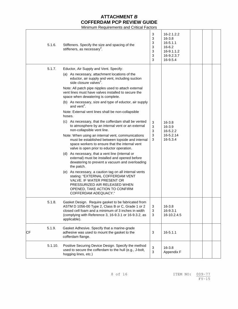
ATTACHMENT B COFFERDAM PCP REVIEW GUIDE Minimum Requirements and Critical Factors
8 of 16 ITEM NO: 009-77 FY-15
5.1.6. Stiffeners. Specify the size and spacing of the stiffeners, as necessary3.
3 3 3 3 3 3 3
16-2.1.2.2 16-3.8 16-5.1.1 16-6.2 16-9.1.1.2 16-9.2.3.7 16-9.5.4
5.1.7. Eductor, Air Supply and Vent. Specify: (a) As necessary, attachment locations of the
eductor, air supply and vent, including suction side closure valves3.
Note: All patch pipe nipples used to attach external vent lines must have valves installed to secure the space when dewatering is complete. (b) As necessary, size and type of eductor, air supply
and vent3. Note: External vent lines shall be non-collapsible hoses. (c) As necessary, that the cofferdam shall be vented
to atmosphere by an internal vent or an external non-collapsible vent line.
Note: When using an internal vent, communications must be established between topside and internal space workers to ensure that the internal vent valve is open prior to eductor operation.
(d) As necessary, that a vent line (internal or external) must be installed and opened before dewatering to prevent a vacuum and overloading the patch.
(e) As necessary, a caution tag on all internal vents stating: “EXTERNAL COFFERDAM VENT VALVE. IF WATER PRESENT OR PRESSURIZED AIR RELEASED WHEN OPENED, TAKE ACTION TO CONFIRM COFFERDAM ADEQUACY."
3 3 3 3 3
16-3.8 16-3.9 16-5.2.2 16-5.2.14 16-5.3.4
5.1.8. Gasket Design. Require gasket to be fabricated from ASTM D 1056-00 Type 2, Class B or C, Grade 1 or 2 closed cell foam and a minimum of 3 inches in width (complying with Reference 3, 16-9.3.1 or 16-9.3.2, as applicable).
3 3 3
16-3.8 16-9.3.1 16-10.2.4.5
CF 5.1.9. Gasket Adhesive. Specify that a marine-grade
adhesive was used to mount the gasket to the cofferdam flange.
3 16-5.1.1
5.1.10. Positive Securing Device Design. Specify the method used to secure the cofferdam to the hull (e.g., J-bolt, hogging lines, etc.)
3 3
16-3.8 Appendix F

ATTACHMENT B COFFERDAM PCP REVIEW GUIDE Minimum Requirements and Critical Factors
9 of 16 ITEM NO: 009-77 FY-15
5.1.10.1. J-Bolt Minimum Requirements. Refer to, and include, Reference 3, Appendix F if a j-bolt is used.
3 3
16-9.2.3.4 Appendix F
5.1.11. Mechanical Fasteners. Specify the fastener type, as necessary.
3 3
16-3.8 16-9.4
5.2. Internal Sealing Blank Design and Documentation. If an internal sealing blank is necessary, require the installation of a less than ½-inch vent valve in the blank and specify: Note: Vent lines shall be less than ½” IPS or else a temporary reducer shall be installed to make the opening less than ½” IPS.
3 3 3 3 3 3 3
16-3.4.2.1.(2) 16-4.7.1.1 16-4.7.1.2 16-4.7.1.5 16-5.2.1 16-5.2.2 App D: 2, 19
5.2.1. Blank conforms to Standard DWG# 845-4612172(latest applicable revision). 5 3.6.1
5.2.2. Gasket conforms to MIL-PRF-1149 (latest revision). 5 6
3.6.1 Cat D-1 & D-3
5.2.3. Fasteners conform to with MIL-DTL-1222J. 5 6
3.6.1 4.15
5.2.4. Positive attachment of a Danger Tag. 3 5
Appendix D: 19 3.6.1.1
5.2.5. Require the blank to be documented on a certified
check-off sheet (Reference 3, Appendix D) verifying its installation and removal.
3 App D: 2, 19, 22, 23

ATTACHMENT B COFFERDAM PCP REVIEW GUIDE Minimum Requirements and Critical Factors
10 of 16 ITEM NO: 009-77 FY-15
5.3. Rigging Plan. Specify a rigging plan to positively secure the cofferdam to the hull, including, as necessary: (a) Lifting requirements (b) Suitable rigging equipment (e.g., chainfalls, turnbuckles,
shackles, bellybands, hogging lines, chafing gear, counterweights)
(c) Securing and attachment requirements (e.g., padeye dimensions and locations) and consideration of rigging load requirements, per Reference 3, Section 9
(d) Manufacturer and weight testing requirements (Lifting Straps, Padeyes, Wire)
(e) Direction and magnitude of expected loads from installation, use, and removal of the cofferdam
(f) Rigging points and supporting structure designed with the factors of safety from Reference 3, Table 16-6.
Note: If rigging to existing ship structure include the following statement: "All existing ship structure selected for rigging purposes, in accordance with this procedure, shall be visually inspected, before its use, for any questionable indications that would appear to compromise its strength (e.g., cracks, unintentional holes, severe corrosion) or items or structure that appear insufficient to carry the intended load(s). This authorization is ONLY applicable to the installation and removal of the cofferdam of this procedure." If Contractor personnel are unclear or unsure as to whether an item is acceptable to rig from, contact the SUPERVISOR immediately for clarification / approval.
3 3 3 3 3
16-3.12 16-5.2.6 16-9.2.3.4 16-9.5.2 16-10.2.5.2
5.4. PREPARATION.
5.4.1. Patch and Plug Inspection. Include Reference 3, Appendix C Patch and Plug Inspection Checksheet and require its completion confirming cofferdam inspection.
3 3 3 3 3 3 3 3 3
16-3.7.3.(b) 16-3.8.(7) 16-4.7.1.3 16-4.7.1.6 16-5.2.8 16-5.2.11 16-6.6.5 16-6.7.4 Appendix C
5.4.2. Freeboard. Note that watertight integrity of 4-feet (MIN) above the maximum anticipated draft shall be maintained.
4 3.1
CF 5.4.3. Hull Opening or Access Cut Location. To locate cofferdam, specify, as necessary:
5.4.3.1. Hull Opening Item #. Referenced on docking drawing.

ATTACHMENT B COFFERDAM PCP REVIEW GUIDE Minimum Requirements and Critical Factors
11 of 16 ITEM NO: 009-77 FY-15
5.4.3.2. Hull Opening Size. Referenced on docking drawing.
5.4.3.3. Hull Fairing. Referenced on docking drawing.
5.4.3.4. Hull Opening Strainer Bars. Detailed on the seachest drawing and referenced on the piping drawing.
5.4.3.5. Access Cut. In lieu of hull opening, detail the location and access cut size.
5.4.3.6. Surface Preparation. Inspect and clean hull surfaces to obtain a 100% seal.
3 3 3 3 3 3
16-4.8.6 16-4.9.2 16-5.4.2 16-6.8.1 16-7.8.1 Appendix C
CF
5.4.3.7. Sealing Surface, Hull. A 3-inch minimum sealing surface on the hull around the opening to accommodate the minimum cofferdam gasket width.
3 3
16-9.3.1.(b) App D: 5
5.4.4. Briefing. Specify a method ensuring cognizant personnel shall have direct knowledge of the requirements before starting the process.
2 2
3.1.7 Attachment A
5.4.5. On-site Documentation. Specify that the following on-site documentation shall be available for the duration of the process, separately or as part of the PCP. (a) Applicable System Drawings. (b) Docking Plan Drawing. (c) Approved PCP (d) Reference 3 (e) Applicable Standard Forms. Including but not
limited to, Reference 3, Appendices C, D and G, as necessary
(f) Rigging Plan (g) Cofferdam Design Package (h) Emergency Flooding Plan (i) Diving Contractor’s Safe Practices Manual
2 2 3
3.1.7 Attachment A 16-10.2.6

ATTACHMENT B COFFERDAM PCP REVIEW GUIDE Minimum Requirements and Critical Factors
12 of 16 ITEM NO: 009-77 FY-15
5.4.6. PCP Control. Specify a method establishing administrative control of the authorized PCP for the duration of the process, including a record of the data demonstrating satisfactory completion of the procedure. Note: This is normally accomplished by a First-Line Supervisor ensuring all personnel shall maintain compliance with PCP requirements.
2 2 2
3.1.8 3.2 Attachment A
5.4.7. Notifications.
5.4.7.1. Government. Notify the Government (G) of the start of the process, in compliance with Reference 7, Para 3.8.2. Label the notification sign-off as: “(V)(G) START OF PROCEDURE”.
2 2 2 7
3.1.11 4.1 Attachment A 3.8.2
5.4.7.2. Ship’s Force Notification of Cofferdam Installation (Location) and Single Valve Protection. Include, and complete, as required, Reference 3, Appendix G Report of Ship’s Responsibility for Patch Installation and/or Single Valve Protection confirming the Ship’s C.O. or Designated Representative have been notified and acknowledge the cofferdam’s location (if installed) and level of valve protection. Note: Unlike single/double valve protection, weld repairs to the hull do not require App. G as implied by Ref. 3, 16-10.2.6.6.
4 4 3 3 3 3 3 3 3 3 3 3 5
3.2.2 3.2.4 16-4.7.1.3 16-4.7.1.4 16-5.2.1 16-5.2.2 16-5.2.9 16-5.2.10 16-6.6.10 16-7.6.4 16-7.6.6 16-10.2.6.6 3.1
5.4.8. Leak Rate. Specify an appropriate leak rate. 3 3 3
16-4.7.1.8 16-5.2.17 16-7.6.6
5.4.9. Inspection Dive. Note a pre-installation inspection dive shall be accomplished verifying existing conditions.
3 3
16-3.6 16-7.7.4
CF
5.4.10. Communications. Specify mandatory two-way communication (e.g., hand-held radio, sound powered telephone) between the Contractor (Surveillance Personnel) and Ship’s Force (Quarterdeck or OOD Station) for the duration of the process.
3 3 3 3 3 3
16-3.4.2.6 16-4.8.4 16-5.2.14 16-5.5.1 16-10.2.5.1 App D: 14, 21
CF 5.4.11. Dewatering.

ATTACHMENT B COFFERDAM PCP REVIEW GUIDE Minimum Requirements and Critical Factors
13 of 16 ITEM NO: 009-77 FY-15
5.4.11.1. Dewatering. If necessary, require installation, tagging (as required) and inspection of all vent lines, eductors and air supply lines (dry chambers), in accordance with Reference 3, Appendix D, as necessary.
3 3 3 3 3 3 3 3 3 3
16-5.2.2 16-5.2.14 16-5.2.15 16-5.2.18.1 16-5.2.18.2 16-5.3.4 16-6.6.7 16-6.7.5 16-7.6.6 Appendix D
CF
5.4.11.2. Pumping, Seawater Supply. If necessary, require maintenance of a seawater supply (supply valve wired open and either a backup fire pump or secondary fire main).
CF 5.4.12. Operational Compliance Check-List. Include, and
complete, the Operational Check-List, Reference 3, Table 16-9.
4 3
3.2.3 16-10.3.1
5.5. INSTALLATION.
5.5.1. Installation Checksheet. Include Reference 3, Appendix D Patch and Plug Installation Check sheet and complete only those steps pertaining to cofferdam installation.
3 3 3 3 3 3
16-3.13 16-4.7.1.3 16-4.7.1.9 16-5.2.11 16-5.2.19 Appendix D
5.5.2. Verify System and Hull Opening. Verify the removed valve or system corresponds to the system blanked and the hull opening.
3 16-5.4.1
CF
5.5.3. Locate and Position Cofferdam. Require: (a) Cofferdam to be located in conjunction with
the Rigging Plan and Inspection Dive. (b) A 4-foot minimum freeboard (conforming to
GOS, S9AA0-AB-GOS-010, Section 045) (c) A 6-inch minimum clearance between the
cofferdam side and hot work area, if applicable. If the 6-inch minimum clearance cannot be maintained provide written justification.
4 3 3 3 3 3 3 3
3.1 3.6 3.12 5.3.5 6.7.6 7.7.5 App C: 1b, 1c App D: 1
CF
5.5.4. Verify Cofferdam Seal (Watertight Integrity). Require Divers to verify cofferdam’s watertight integrity, and, if necessary, retightening of the primary means of cofferdam attachment to establish a watertight seal.
3 Appendix D

ATTACHMENT B COFFERDAM PCP REVIEW GUIDE Minimum Requirements and Critical Factors
14 of 16 ITEM NO: 009-77 FY-15
5.5.4.1. Notification of Cofferdam Seal. Require Lead Shop notification that a seal has been established.
3 Appendix D
CF
5.5.5. Internal Seal Blank. If necessary, require: (a) The installation of an internal seal blank,
conforming to the specified design requirements, immediately after removal of the damaged (or repair) component (internal piping or watertight boundary is opened) to maintain double-valve protection.
(b) The Contractors to confirm that an internal seal blank with a less than ½” diameter vent valve has been installed immediately after removal of the damaged (or repair) component.
3 3 3 3 3 3 3
16-3.4.2.1.(2) 16-4.7.1.1 16-4.7.1.2 16-4.7.1.5 16-5.2.1 16-5.2.2 App D: 2, 19
CF 5.5.6. Test & Inspection Plan; Acceptance & Rejection Criteria. Include a Test & Inspection Plan denoting the relevant acceptance and rejection criteria, in compliance with Reference 7, Paras. 3.4.1 and 3.5.1.
2 2 7 7
3.6.1 Attachment A 3.4.1 3.5.1
5.5.7. Monitoring. Require cognizant personnel (e.g., Divers or Ship’s Force) to monitor watertight integrity of all applicable cofferdams (with dewatering equipment secured) while actually providing single or double-valve protection at intervals no greater than every 7 days for patches and continuously for dry chambers (when occupied). Note 1: The vent valve on internal seal blanks facilitates internal vent cofferdam monitoring. Note 2: The blank vent valve may be left shut when not temporarily opened by the ship's sounding and security detail for patch or plug seal monitoring or, upon approval by the Ship, the blank vent valve may be left continuously open to maintain cofferdam differential pressure.
3 3 3 3
16-5.2.2 16-5.2.18 16-6.7.2 Appendix D: 19

ATTACHMENT B COFFERDAM PCP REVIEW GUIDE Minimum Requirements and Critical Factors
15 of 16 ITEM NO: 009-77 FY-15
5.6. REMOVAL.
5.6.1. Removal Checklist. Remove cofferdam and complete those remaining steps in Reference 3, Appendix D Patch and Plug Installation Checksheet applicable to the removal phase of the cofferdam procedure.
3 3 3 3 3 3 3 3 3 3
16-3.13 16-4.7.1.3 16-4.7.1.9 4.8.1 4.9.7 16-5.2.11 16-5.2.19 5.5 7.9 Appendix D
CF 5.6.2. Removal/Reinstallation Equipment, On-site.
Equipment to move/manipulate the component shall be available on-site.
CF
5.6.3. Cofferdam Seal Verification. Either open the ½-inch vent valve or loosen blank fasteners to slightly spread (open) the seal and verify the cofferdam is holding back sea pressure. If leakage exists correct cofferdam seal.
3 3 3
4.8.9 4.8.10 Appendix D
CF 5.6.4. Internal Sealing Blank. Remove internal sealing
blank and retain on-site for immediate installation, if necessary.
3 Appendix D
CF
5.6.5. Double Valve Protection. Verify reestablishment of double-valve protection after component has been installed and 24-hour surveillance or diver stand-by for single-valve protection is no longer required.
3 Appendix D
CF 5.6.6. Divers Stand-By, Removal. Require Divers to be
on stand-by during removal of internal blank and re/installation of component.
3 Appendix D
CF
5.6.7. Verify System Integrity. Require loosening of cofferdam after the component is installed to verify the flange seal is tight (zero leaks) and, if not, the Divers shall retighten the cofferdam to reestablish watertight integrity of the component. When seal is verified, remove the cofferdam.
3 Appendix D

ATTACHMENT B COFFERDAM PCP REVIEW GUIDE Minimum Requirements and Critical Factors
16 of 16 ITEM NO: 009-77 FY-15
Notes. 1. Items referenced to this note are considered “critical factors, which have direct bearing on the process
quality and safety” in accordance with Reference 2, Para. 3.1.3 and are either only generally implied in the References or are not readily specified but are nevertheless considered critical and required for a successful cofferdam process. These Items are marked “CF” in this Review form.
2. Non-standard cofferdams are cofferdams other than those provided by Reference 4, Section 9. 3. Can be included as part of design sketch.

1 of 2 ITEM NO: 009-78 FY-15
NAVSEA STANDARD ITEM FY-15 ITEM NO: 009-78 DATE: 07 NOV 2013 CATEGORY: II 1. SCOPE: 1.1 Title: Passive Countermeasures System (PCMS) Material Repair/
Installation Requirements; accomplish 2. REFERENCES: 2.1 Standard Items 2.2 RIM 05T1-99, Passive Countermeasures System (PCMS)
Repair/Installation Methods 2.3 PHS&T 05T1-07, Passive Countermeasures System Packaging, Handling,
Storage and Transportation Plan 2.4 ACD 05P1-13, Passive Countermeasures System (PCMS) Access, Material
Control and Disposal Manual 3. REQUIREMENTS: 3.1 Remove existing and install new PCMS material in accordance with 2.2 through 2.4. 3.1.1 Accomplish additional PCMS material handling and storage requirements in accordance with 2.3. (V) "ENVIRONMENTAL REQUIREMENTS" 3.1.2 Verify the environmental requirements of Section C.1 of 2.2 are met prior to application of primers, tiles, caulking, and paint. (V) "WELD FAIRING" 3.1.3 Verify the fairing of weld seams is in accordance with Section C.3 of 2.2. (V)(G) "FINAL INSPECTION" 3.1.4 Accomplish a final inspection of newly installed PCMS material to verify correct installation.

2 of 2 ITEM NO: 009-78 FY-15
3.1.5 Accomplish surface preparation and preservation for topcoat of new PCMS material in accordance with Section C.6 of 2.2. 3.2 Accomplish the requirements of 009-32 of 2.1 for new and disturbed surfaces. 4. NOTES: 4.1 None.

1 of 4 ITEM NO: 009-79 FY-15
NAVSEA STANDARD ITEM FY-15 ITEM NO: 009-79 DATE: 29 JUL 2011 CATEGORY: I 1. SCOPE: 1.1 Title: Government Owned Material (GOM); status reporting 2. REFERENCES: 2.1 None. 3. REQUIREMENTS: 3.1 Provide an accurate accounting of Government Owned Material (GOM), traceable to the Lowest Replaceable Unit (LRU), in the custody of the contractor. For this tasking, GOM is defined as government furnished material (GFM) and contractor acquired material (CAM) which the Navy has either paid for or provided directly to the contractor. 3.2 Prepare and submit one legible copy of GOM Status Reports in approved transferrable media (similar or equal to Excel). 3.2.1 This report shall specify all the current inventory of GOM baseline, residual, and excess assets including COSAL material, installation and checkout (INCO) spares, GFM, and CAM. Specific content requirements shall be as specified in 3.2.2 and shall include the following: 3.2.1.1 Allowance Parts List/Allowance Equipage List (APL/AEL). An alphanumeric code, minimum of 8 characters and maximum of 11 characters, that identifies the unique characteristics of an equipment or system provisioned by the Naval Inventory Control Point, or the non-installed material collectively known as equipage. 3.2.1.2 Document GFM Requisition/CFM purchase order number. 3.2.1.3 National Item Identification Number. Represents the last 9 digits of the 13-digit Naval Stock Number and identifies a specific item catalogued in the Federal Supply System. 3.2.1.4 Part Number. A manufacturer’s part numbers, drawing numbers, and model, type, or source controlling numbers used to identify an item of production or supply.

2 of 4 ITEM NO: 009-79 FY-15
3.2.1.5 Commercial and Government Entity (CAGE). A 5-digit number assigned to an individual supplier, manufacturer, corporation, or government activity for identification purposes. 3.2.1.6 Unit of Issue. A 2-character abbreviation code used to identify the types of units under which material is issued. For example, shoes would be issued as a pair (PR), while hammers would be issued one at a time or each (EA). 3.2.1.7 Allowance/Required Quantity. The total number of a given item of replacement allowed onboard. 3.2.1.8 Quantity on Order. The number of a given item for which requisitions are in process. 3.2.1.9 Quantity Received. The number of a given item acquired as a result of a requisition. 3.2.1.10 Quantity on Hand. The number of a given replaceable item currently in the storeroom/storage location. 3.2.1.11 Unit Price. The cost of the unit of issue (i.e., gross, pair, each, quart, gallon, ton, ounce, etc.). 3.2.1.12 Extended Price. The cost calculated by multiplying the unit price by the quantity of items. 3.2.1.13 Material Accessibility Code (MAC). A 2-character alphabetic code that defines the material's intended use and disposition. Generally speaking, excess assets are available as free issue redistributions while baseline and residual assets are either non-available for redistribution or are negotiable at the program manager's discretion. A single item may have multiple MACs assigned to it; some of its quantity on hand could be in each category. Valid MACs include IC (Inaccessible and contractually required), ID (Inaccessible and Deferred), and AR (Accessible and Residual). 3.2.1.14 Unit Identification Code. A 5-digit accounting number that identifies a ship, shore activity, operational unit, agency, contractor or other organized entity that may be involved in acquiring and/or managing material. 3.2.1.15 Type Number Code. A one-digit alphabetic code that identifies the data in position 12-28 as either a document number [R] or a contract number (P). 3.2.1.16 Condition Code. A one-digit alphabetic code that identifies the condition of the material, whether it is ready for issue or in need of some level of repair. 3.2.1.17 Cognizance Code. A 2-position code. The first position identifies the stores account to which the item belongs and the

3 of 4 ITEM NO: 009-79 FY-15
second position identifies the combined technical and inventory manager having jurisdiction over the item. 3.2.1.18 Federal Supply Classification. A 4-position code assigned to designate various groups of common use, commercial type items. 3.2.1.19 COAR/Material Group. A 6-position code locally assigned by the SUPERVISOR to indicate the modernization program under which the work on the ship is being performed or the outfitting material group material is being purchased to support. 3.2.1.20 Item Name. A 48-position nomenclature assigned to an item to describe the item for allowance purposes. 3.2.1.21 Technical Characteristics. A 200-character field used to describe the technical characteristics of an item. 3.2.2 The GOM Report Format (character positions, data element numbers, and field lengths) shall use the following table as an illustration of the data elements with their respective character positions and field lengths: POSITION DEN DATA DESCRIPTION PICTURE REMARKS 1-11 D008G APL/AEL X (11) 12-28 K002/P699 Document/Contract Number X (17) 29-37 D046D NIIN X (9) N/R if no NSN
assigned 38-67 D001W Part Number X (30) N/R if NSN
assigned 68-72 C035 CAGE X (5) N/R if NSN
assigned 73-74 C005 Unit of Issue X (2) 75-79 E372 Allowance Quantity 9 (5) 80-84 F977C Quantity on Order 9 (5) 85-89 F977D Quantity Received 9 (5) 90-94 A012 Quantity on Hand 9 (5) 95-105 B053 Unit Price 9 (11) 106-116 G101A Extended Price 9 (11) 117-118 Material Access Code (AF) X(2) 119-120 Material Access Code (AR) X(2) 121-122 Material Access Code (IC) X(2) 123-124 Material Access Code (ID) X(2) 125-129 A002 Unit Identification Code X (5) 130 T088 Type Number Code X 131 SD041 Condition Code X 132-133 C003 Cog X(2) 134-137 C042 FSC X(4)

4 of 4 ITEM NO: 009-79 FY-15
POSITION DEN DATA DESCRIPTION PICTURE REMARKS 138-143 COAR X(6) 144-191 C004C Item Name X(48) 192-392 T059B Technical Characteristics X(200) N/R if NSN
assigned N/R = Not Required 3.3 Submit the GOM Status Report to the SUPERVISOR 4 working days prior to the 50 percent conference and 5 working days after the end of the availability. 4. NOTES: 4.1 The GOM Status Report will be invoked in the solicitation for multi-ship/multi-year availabilities.

1 of 2 ITEM NO: 009-80 FY-15
NAVSEA STANDARD ITEM FY-15 ITEM NO: 009-80 DATE: 29 JUL 2011 CATEGORY: I 1. SCOPE: 1.1 Title: Ship's Facilities; provide 2. REFERENCES: 2.1 None. 3. REQUIREMENTS: 3.1 Accomplish the following requirements to keep the ship habitable and maintain the ship's facilities operational at times when spaces are inhabited by the crew. 3.1.1 Maintain operational sanitary services. 3.1.2 Identify span of time each CHT zone will be taken out of service. 3.1.3 Install and maintain temporary, primary, and back-up CHT pumps during such time that ship's CHT system is inoperative. 3.1.4 Ensure that the ship's power, steam, fire main, seawater service system, flushing system, heating system, CHT system, potable water, air conditioning, and ventilation is maintained operational. 3.1.5 Install temporary cables, jumpers, pumps, spool pieces, valves, hoses, and ducts when required to maintain systems operational. 3.2 Coordinate disruption of the facilities listed in 3.1 and systems listed in 3.1.4 with the ship via the SUPERVISOR. 3.3 Submit one legible copy, in approved transferrable media, of a detailed schedule showing when each facility/system will be disrupted to accomplish 3.1.5 and include the following: 3.3.1 Original schedule is due 5 calendar days prior to availability start date. 3.3.2 Submit updated schedules weekly throughout the entire availability.

2 of 2 ITEM NO: 009-80 FY-15
3.3.3 Include each compartment disrupted and specify the system(s) affected, with the scope of the disruption. 3.4 Remove the temporary installations and restore the systems to operational conditions when directed by the SUPERVISOR. 4. NOTES: 4.1 The contractor is only required to maintain those systems operational which he disturbs or disrupts in the performance of work in the Job Order, and only to the extent possible, using temporary methods consistent with 3.1.5.

1 of 3 ITEM NO: 009-81 FY-15
NAVSEA STANDARD ITEM FY-15 ITEM NO: 009-81 DATE: 17 JAN 2013 CATEGORY: I 1. SCOPE: 1.1 Title: Compartment Closeout; accomplish 2. REFERENCES: 2.1 None. 3. REQUIREMENTS: 3.1 Submit one legible copy, in approved transferrable media, of a compartment closeout schedule to the SUPERVISOR no later than the 50 Percent Review Conference. 3.1.1 The compartment closeout schedule shall contain the following minimum information: 3.1.1.1 A list of compartments where work has been or remains to be accomplished. Include each compartment number and name. Work not completed shall be identified by the Work Item number. 3.1.1.2 A brief of the work that remains to be accomplished by the contractor. 3.1.1.3 Any impact that known Ship's Force work will have on the contractor. 3.1.1.4 The date when the contractor expects to complete his work within each compartment. Highlight major trouble spots. 3.1.1.5 Index the compartment closeout schedule by compartment number listing the page number of where the information about the compartment can be located. 3.1.2 The compartment closeout schedule shall provide for completion of the following compartments, including associated machinery, equipment, electrical, alarm, control, piping, and ventilation systems, prior to the crew move aboard milestone date:

2 of 3 ITEM NO: 009-81 FY-15
3.1.2.1 Messing, berthing, and living compartments, including galley, scullery, pantry, mess decks, walk-in freezer, chill and thaw boxes, dry provisions and breakout storerooms, wardroom, CPO mess, berthing compartments, staterooms, lounges, wash rooms, water closets and showers, laundry, and associated access routes and passageways that have had other than cable installation performed. 3.1.2.2 Refrigeration and air conditioning machinery rooms 3.1.2.3 CHT machinery spaces and tanks 3.1.2.4 Medical and dental spaces (V)(G) "COMPARTMENT INSPECTION" 3.2 Accomplish a joint inspection with the SUPERVISOR and the Commanding Officer's designated representative upon completion, inspection, and acceptance, by the contractor, of work within each compartment. 3.2.1 Submit one legible copy, in approved transferrable media, of a report to the SUPERVISOR after each compartment inspection, listing the discrepancies. Identify each discrepancy as Contractor responsibility or Government responsibility. The 3 parties will sign the above report as work being complete. Turn over each compartment to Ship's Force for maintenance and indicate on the updated compartment closeout schedule as complete. 3.3 Update the compartment closeout schedule at the weekly progress meeting after the first report is published. 3.3.1 Highlight changes from the previous compartment closeout schedule. 3.3.2 Highlight each discrepancy in the spaces in 3.1.2 that cannot be corrected prior to crew move aboard milestone date, providing the reason and expected completion date. 4. NOTES: 4.1 The ship's Commanding Officer will furnish the SUPERVISOR the work by compartment, including the schedule, which is planned for accomplishment by Ship's Force on a weekly basis. 4.2 For purposes of this item, the term compartment includes compartments, tanks, and voids. 4.3 The crew move aboard evolution is a difficult and complex one. Key areas of concern are: safety of the crew; sanitation and serviceability of food preparation, serving, and eating areas; livability of berthing and sanitary spaces; cleanliness.

3 of 3 ITEM NO: 009-81 FY-15
4.4 Interface conflicts in the closeout schedule will be resolved as they occur. 4.5 For purposes of this item, the terms "space/spaces", "room/rooms", and "compartment/compartments" are synonymous.


1 of 1 ITEM NO: 009-82 FY-15
NAVSEA STANDARD ITEM FY-15 ITEM NO: 009-82 DATE: 29 JUL 2011 CATEGORY: I 1. SCOPE: 1.1 Title: Data Requirements When Installing an Equal Component Vice
Specified Component; provide 2. REFERENCES: 2.1 None. 3. REQUIREMENTS: 3.1 Submit one legible copy, in approved transferrable media, of the following data to the SUPERVISOR in each instance when the Work Item allows, and the contractor chooses, to install "an equal component" in lieu of the component specified by the Work Item. Provide data to compare the equal component to that specified including the following: 3.1.1 Physical dimensions of each 3.1.2 Bolting pattern required to install the component 3.1.3 Power requirements 3.1.4 Size, location, and type of miscellaneous service connections 3.1.5 Modifications required for installation 3.1.6 Comparison of the characteristics, i.e., gallons per minute, cubic feet per minute, and temperature ranges 3.1.7 Submission of the reports shall be 20 days after award of CNO availabilities and 2 days after award for other availabilities. 4. NOTES: 4.1 None.


1 of 2 ITEM NO: 009-83 FY-15
NAVSEA STANDARD ITEM FY-15 ITEM NO: 009-83 DATE: 17 JAN 2013 CATEGORY: I 1. SCOPE: 1.1 Title: Wire Rope Fitting Verification; provide 2. REFERENCES: 2.1 S9086-UU-STM-010/CH-613, Wire and Fiber Rope and Rigging 3. REQUIREMENTS: 3.1 Comply with the following specifications when procuring wire rope fittings. 3.1.1 SOCKETS - RR-S-550 3.1.2 FIEGE-TYPE - MIL-S-21433 3.1.3 SWAGE SLEEVES - Commercial, supplied by the same manufacturer as the swaging machine 3.1.4 THIMBLES - FF-T-276 Type 3 only 3.1.5 SHACKLES - RR-C-271 3.1.6 BLOCKS - MIL-B-24141 3.2 Comply with the following specification when procuring wire rope. 3.2.1 WIRE ROPE AND STRAND – RR-W-410 3.3 Fabricate wire rope assemblies from the materials specified in 3.1 in accordance with the assembly and testing requirements of 2.1. 3.4 Submit one legible copy, in approved transferrable media, to the SUPERVISOR of certification from each manufacturer that states that the wire rope and all components listed in 3.1.1 through 3.1.6 comply with the requirements and specifications listed in 3.1 and 3.2. 3.5 Verify each fitting is legibly marked with manufacturer's name or trademark and size. 3.5.1 Shackles and blocks shall also be marked with safe working load.

2 of 2 ITEM NO: 009-83 FY-15
3.5.2 Thimbles are not required to be marked. 3.6 In addition to the certifications of 3.4, submit one legible copy, in approved transferrable media, of testing results in accordance with 2.1. Provide certification documentation of qualified assembly personnel in accordance with 2.1 if required. 4. NOTES: 4.1 None.

1 of 2 ITEM NO: 009-84 FY-15
NAVSEA STANDARD ITEM FY-15 ITEM NO: 009-84 DATE: 17 JAN 2013 CATEGORY: I 1. SCOPE: 1.1 Title: Accountability of Temporary Fasteners; provide 2. REFERENCES: 2.1 None. 3. REQUIREMENTS: 3.1 Maintain a single log/file of installed/removed temporary fasteners with the following information: 3.1.1 System 3.1.2 Component (valves, flanges, foundations, brackets) 3.1.3 Location (deck, frame, port, starboard, tank, manhole) 3.1.4 Company name/badge number/name of mechanic 3.1.5 Date installed/date removed 3.2 Paint temporary fasteners blaze orange unless an alternate color has been authorized by the SUPERVISOR. 3.2.1 Minimum requirements for painting fasteners are as follows: Nut Bearing faces (top) Bolt Top of Bolt Head Stud Both ends of stud Washer Faces (Edge and Bottom of washer) 3.3 Remove temporary fasteners prior to any testing, lagging, and/or painting of systems or components. 3.4 Logging-in of temporary fasteners shall be accomplished no later than the end of the work shift.

2 of 2 ITEM NO: 009-84 FY-15
4. NOTES: 4.1 For purposes of this item, temporary fasteners are defined as those fasteners that are installed in lieu of the final fasteners that are specified for system installation. Examples would include temporary fasteners used to hold fittings, valves, or machinery in place.

1 of 3 ITEM NO: 009-85 FY-15
NAVSEA STANDARD ITEM FY-15 ITEM NO: 009-85 DATE: 19 JUL 2007 CATEGORY: II 1. SCOPE: 1.1 Title: Government Sponsored Planning Yard/Configuration Data Manager
(CDM) On-Site Representative Facility; provide 2. REFERENCES: 2.1 None. 3. REQUIREMENTS: 3.1 Provide a separate, lockable, and secure office space for use by the Government Sponsored Planning Yard/CDM On-Site Representative furnished with 2 desks with chairs, lights, heat, air conditioning, electrical outlets, sanitary facilities, filing cabinets, telephone service, janitorial service, and 2, 15-pound fire extinguishers and 24-hour service for the entire contract period. 3.1.1 The facility shall have a minimum of 240 square feet of floor space. 3.1.2 The facility shall be located within one-quarter mile of the ship. 3.1.2.1 Provide a parking area adjacent to the facility. The area shall be lighted and accommodate 2 automobiles simultaneously. 3.1.3 Lighting shall provide 28 foot candles of illumination measured at the desktop level. 3.1.4 Heating and air conditioning shall be capable of maintaining the temperature between 65 and 78 degrees Fahrenheit. 3.1.5 Provide 2 double-pedestal desks 30-inches wide by 60-inches long. 3.1.5.1 Provide one telephone desk set and one 115-volt, shock resistant, double electrical receptacle for each desk. Each receptacle shall be a convenient height and located adjacent to each desk.

2 of 3 ITEM NO: 009-85 FY-15
3.1.5.2 Provide one swivel chair and one straight-back chair for each desk. 3.1.6 Provide telephone communications with separate circuits for each desk set, between the facility, shipyard, ship, and the municipal telephone system. One telephone line shall be capable of digital transmission. 3.1.6.1 Telephone systems designated long distance shall be installed in such a manner that the only way long distance calls can be made will be with a long distance calling card (credit card) that shall be obtained by the On-Site Representative prior to availability start date. 3.1.7 Provide 4-drawer filing cabinets with lock and keys. 3.1.8 Provide sanitary facilities equipped with drains, hot and cold potable water, and the following: 3.1.8.1 Hot water shall be maintained at 120 to 140 degrees Fahrenheit. 3.1.8.2 One lavatory 3.1.8.3 One water closet 3.1.8.4 One soap dispenser 3.1.8.5 One towel dispenser 3.1.9 Facilities shall be provided 2 days prior to contract start date through 2 days after the contract completion date unless otherwise specified. 3.2 Provide janitorial services to include sweeping, mopping, buffing, and trash pickup on a daily basis. 3.3 The facility shall be in accordance with local building codes, sanitary and current fire regulations. The facility shall include smoke alarms, 2, 15-pound fire extinguishers, and sprinkler systems. 3.4 Furnishings and equipment in this item shall be maintained in a fully operable condition by the contractor. 3.5 The facility shall be delivered to the Government clean, sanitary, damage free, and vermin free. 4. NOTES: 4.1 The On-Site Representative will retain the keys during the entire contract period.

3 of 3 ITEM NO: 009-85 FY-15
4.2 The SUPERVISOR will identify the Government Sponsored Planning Yard/CDM On-Site Representatives upon request of the contractor. 4.3 The Government Sponsored Planning Yard/CDM On-Site Representatives shall obtain the telephone credit card specified in 3.1.6.1 from their command.


1 of 4 ITEM NO: 009-86 FY-15
NAVSEA STANDARD ITEM FY-15 ITEM NO: 009-86 DATE: 01 AUG 2008 CATEGORY: I 1. SCOPE: 1.1 Title: Recovery of Chlorofluorocarbon (CFC) Refrigerants and Fire
Suppressant Halon (H) Materials; accomplish 2. REFERENCES: 2.1 49 CFR Part 173, General Requirements for Shipments and Packagings 3. REQUIREMENTS: 3.1 Recover CFC refrigerants and halon materials listed in 4.2 that are not recycled back into the specific system's equipment from which they were removed as follows: 3.1.1 Fire suppression (halon) cylinders and canisters with electrical charges or initiators must be deactivated and safety caps must be used to cover exposed actuating mechanisms and discharge ports prior to shipping the intact cylinder. 3.1.2 Recover other halon and CFC materials for turn-in to the DoD ODS Reserve at the Defense Depot Richmond VA (DDRV). Empty cylinders shall be used to recover the materials. Empty recovery cylinders can be requisitioned through normal MILSTRIP stock ordering procedures from DDRV. The cylinders used to recover CFC shall be painted orange and cylinders used for halon shall be painted red. Both cylinders shall have yellow tops and shall also have dual port valves to ease the recovery process. 3.1.2.1 Do not mix new materials with used materials and do not mix different types of materials in the same cylinders. 3.1.3 Ensure the recovered materials cylinder is tagged. The tag should be placed beneath the cylinder protective cap or attached securely to the container. Do not stencil on cylinder. The tag shall contain the following information: 3.1.3.1 The shipper's DOD Activity Address Code (DODAAC). If the turned-in material originates from a ship or submarine, use the DODAAC of the ship/submarine on the tag.

2 of 4 ITEM NO: 009-86 FY-15
3.1.3.2 The shipping activity with point of contact and telephone number. 3.1.3.3 The National Stock Number (NSN) that applies to the filled cylinder being returned. 3.1.3.4 The identity of the recovered material (Navy recovered R-XXX, CFC-XXX, or HALON-XXXX). 3.1.3.5 The amount, in pounds, of recovered materials in the cylinder. Do not fill more than 80 percent of its water weight capacity. 3.1.3.6 Apply a warning/hazardous label to the cylinder in compliance with 2.1. 3.1.3.7 The quantity of containers on the pallet or within the shipping crate. When multiple containers with the same NSN are shipped palletized or in a box/crate, apply only one tag/label to the shipment, not to each item. 3.2 Prior to shipping the reclaimed materials to DDRV, notify the SUPERVISOR so that a DD Form 1348-1 MILSTRIP can be prepared and transaction authorization procured. 3.3 Upon receipt of the completed DD Form 1348-1, and transaction authority from the SUPERVISOR, ship the reclaimed materials to: Defense Depot Richmond Virginia (DDRV) SWO400 Cylinder Operations 8000 Jefferson Davis Highway Richmond, VA 23297-5000 4. NOTES: 4.1 If your activity is personally transporting ODS to the DoD ODS Reserve, be sure to schedule your delivery with the DDRV Dispatch Office at DSN 695-3834 or (804) 279-3834. 4.2 Recovery Material - CFC's and Halons: PRODUCT TYPE PRODUCT TYPE WEIGHT CYLINDER WATER WEIGHT R-11 59 42 170 122 1,400 1,000 100 (drum) N/A 200 (drum) N/A 650 (drum) N/A

3 of 4 ITEM NO: 009-86 FY-15
PRODUCT TYPE PRODUCT TYPE WEIGHT CYLINDER WATER WEIGHT R-12 45 42 145 122 1,190 1,000 R-113 6 ounces N/A 1 pint N/A 1 quart N/A 1 gallon N/A 5 gallons (60 lbs) N/A 100 lbs (can) N/A 200 lbs (drum) N/A 55 gallons (drum) N/A Note: Only unused CFC-113 solvent contained in original drums or cans with unbroken seals shall be returned to DDRV. Used R-113 refrigerant can also be returned. Call (804) 279-5203 or DSN 695-5203 for specific turn-in guidance. R-114 57 42 165 122 1,350 1,000 R-500 43 42 127 122 1,045 1,000 R-502 44 42 125 122 1,050 1,000 H-1202 160 122 H-1211 1-5 6-10 11-20 21-60 61-125 126-200 122 200 122 201-340 341-1,500 1,000 1,500 1,000

4 of 4 ITEM NO: 009-86 FY-15
PRODUCT TYPE PRODUCT TYPE WEIGHT CYLINDER WATER WEIGHT H-1301 1-5 6-10 11-20 21-70 71-100 101-117 117 118-125 126-150 150 122 151-200 201-260 261-350 351-530 531-600 601-1,240 1,240 1,000 4.3 Current NSNs for cylinders are available from the SUPERVISOR. 4.4 Condition codes for cylinders are as follows: 4.4.1 Condition Code A: To be used for returning original cylinders whose seal was never broken or for recovery cylinders. 4.4.2 Condition Code B: To be used for returning full, original cylinders or for standard DOD refillable cylinders. 4.4.3 Condition Code F: To be used to return partially depleted cylinders whose purity cannot be guaranteed or for returning other (non-standard/commercial) cylinders. 4.5 Definition of Recover - To remove refrigerant in any condition from a system and store it in an external container without necessarily testing or processing it in any way.

1 of 2 ITEM NO: 009-87 FY-15
NAVSEA STANDARD ITEM FY-15 ITEM NO: 009-87 DATE: 17 JAN 2013 CATEGORY: I 1. SCOPE: 1.1 Title: Chemical Disinfection Procedures; accomplish 2. REFERENCES: 2.1 NAVMED P-5010-6, Manual of Naval Preventive Medicine, Chapter 6,
Water Supply Afloat 3. REQUIREMENTS: 3.1 Accomplish disinfection of each affected potable water system, tank, pump, piping, and hoses in accordance with 2.1. 3.2 Accomplish a halogen (chlorine) residual test for each affected potable water tank and system. Acceptable free available chlorine (FAC) shall meet minimum levels specified in 2.1. 3.2.1 Submit one legible copy, in approved transferrable media, of the chlorine residual test to the SUPERVISOR not later than 24 hours after the completion of the test, stating that minimum FAC level has been met in accordance with 2.1. 3.3 Secure and tag out each affected potable water system upon completion of the chlorine residual test. 3.4 Accomplish a bacteriological test for each affected potable water system. 3.4.1 Bacteriological testing must be accomplished at laboratories certified by state regulatory agencies in states having primacy, or by the Regional EPA Office in states not having primacy. 3.4.2 Submit one legible copy, in approved transferrable media, of completed report to the SUPERVISOR not later than 24 hours after the completion of the test, with certification that the water is safe for human consumption. 3.5 Remove each tag upon completion of satisfactory bacteriological test and release each potable water system for Ship's Force use.

2 of 2 ITEM NO: 009-87 FY-15
3.6 Accomplish localized disinfection of new and disturbed pipe fittings, pipe ends, and valves in accordance with Article 6-23c of 2.1. 3.7 Remove and dispose of chlorinated water and all rinse water in accordance with federal, state, and local laws, codes, ordinances, and regulations. 4. NOTES: 4.1 Do not take calcium hypochlorite in dry powder form aboard ship. Mixing is to be done ashore. 4.2 2.1 can be accessed at: http://navymedicine.med.navy.mil (use link to Navy Medicine Directives, Publications and Manuals) or http://www-nehc.med.navy.mil/downloads/prevmed/NewP-5010-6.pdf

1 of 4 ITEM NO: 009-88 FY-15
NAVSEA STANDARD ITEM FY-15 ITEM NO: 009-88 DATE: 29 JUL 2011 CATEGORY: I 1. SCOPE: 1.1 Title: Collection, Holding and Transfer (CHT) and Mogas Tanks,
Spaces, and Piping, including Sewage or Mogas-Contaminated Tanks, Spaces, and Piping; certify
2. REFERENCES: 2.1 Standard Items 2.2 29 CFR Part 1915, Occupational Safety and Health Standards for
Shipyard Employment 2.3 NFPA Standard 312, Standard for Fire Protection of Vessels During
Construction, Repair, and Lay-up 2.4 NFPA Standard 306, Standard for the Control of Gas Hazards on
Vessels 2.5 S9086-T8-STM-010/CH-593, Pollution Control 2.6 Compressed Gas Association Commodity Specification for Air, Pamphlet
G-7.1 2.7 29 CFR Part 1910.134, Occupational Safety and Health Standards,
Respiratory Protection 3. REQUIREMENTS: 3.1 Certify ENTER WITH RESTRICTIONS, SAFE FOR WORKERS and/or SAFE FOR HOT WORK in accordance with 2.2 through 2.4, using 2.5 and 2.6 for guidance, Collection, Holding and Transfer (CHT) and Mogas tanks, spaces, and associated piping, and inspect and certify adjacent tanks, spaces, or piping, where the scope of repairs will result in a need for certification during the accomplishment of this Job Order. 3.1.1 A National Fire Protection Association (NFPA) Certified Marine Chemist shall be present during the opening of CHT or Mogas tanks, spaces, or associated piping. The Marine Chemist shall personally certify all CHT or Mogas tanks, spaces, and associated piping for initial entry.

2 of 4 ITEM NO: 009-88 FY-15
3.1.2 Submit one legible copy, in approved transferrable media, of a list of tanks or spaces to be certified to the SUPERVISOR at least 24 hours prior to commencement of work. 3.1.3 Accomplish the requirements of 009-09 of 2.1 for a step-by-step procedure of how the certification process will be accomplished. 3.1.3.1 Procedures for CHT systems shall include, as a minimum, personnel requirements, notification of emergency response personnel, disinfecting of CHT tank and associated piping, removal of product, diagram and tag-out of affected piping, protective clothing, respiratory protection, ventilation requirements, and a list of spaces affected. 3.1.3.2 Procedures for Mogas systems shall include, as a minimum, personnel requirements, notification of emergency response personnel, removal of product from the draw-off tank and Mogas tank and associated piping, removal of inert gas (carbon dioxide) from the cofferdam around the Mogas tank, tag-out of affected Mogas and inert gas (CO2) piping, fire protection/fire prevention, protective clothing, respiratory protection, ventilation requirements, and control of other hazards such as benzene and lead. 3.2 Provide a written notice of opening of CHT and Mogas tanks, spaces, and associated piping. 3.2.1 Deliver written notification to the SUPERVISOR and the Commanding Officer's designated representative at least 4 hours prior to the planned opening of CHT or Mogas tanks, spaces, and associated piping. 3.2.2 Deliver written notification to the SUPERVISOR and the Commanding Officer's designated representative of opening of CHT or Mogas tanks, spaces, and associated piping planned over a weekend or Monday following that weekend no later than 0900 on the Friday immediately preceding that weekend. 3.2.3 Deliver written notification to the SUPERVISOR and the Commanding Officer's designated representative of opening of CHT or Mogas tanks, spaces, and associated piping planned on a federal holiday and on the day following the federal holiday no later than 0900 of the last working day preceding the federal holiday. 3.3 Accomplish the requirements of 2.2 for tanks, spaces, or piping that have the potential to become Immediately Dangerous to Life or Health (IDLH). 3.3.1 Spaces that are determined to contain IDLH atmospheres shall never be entered except for emergency rescue or for short duration for installation of ventilation equipment in accordance with 2.2 and 2.7, and the requirements of 3.3.1.1 and 3.3.1.2. When entering IDLH spaces for the purpose of installing ventilation, notify the SUPERVISOR prior to entry. Notifications of rescue shall be made as soon as possible.

3 of 4 ITEM NO: 009-88 FY-15
3.3.1.1 Provide a full facepiece, pressure demand, self-contained breathing apparatus (SCBA) certified by National Institute for Occupational Safety and Health (NIOSH) for a minimum service life of 30 minutes, or a combination, full facepiece, pressure demand supplied-air respirator (SAR) with an auxiliary self-contained air supply. The size/volume of the auxiliary self-contained air supply shall be based on the contractor's assessment of the unique characteristics/hazards of the space being entered to allow employees to safely escape. 3.3.1.2 In the case of Mogas tanks and the associated cofferdams, the auxiliary self-contained air supply shall be a minimum of 15 minutes or more depending on the required assessment in 3.3.1.1. 3.3.2 NIOSH-approved atmosphere-supplying respirators shall be used by personnel entering CHT tanks, Mogas tanks or spaces, or opening associated piping. Atmosphere-supplying respirators may be either a combination, full facepiece, pressure demand SAR, or a full facepiece, pressure demand SCBA. The source of breathing air for SARs shall be either a compressor capable of delivering an adequate quantity of breathing air at the pressure required by the respirators used and meeting the requirements of the specification for Grade D breathing air described in 2.6, or a bank of cylinders cascading to provide at least 4 to 6 hours of breathing air meeting the above specifications at the pressure needed by the respirators used. The source of breathing air for SCBAs shall meet the requirements of 2.6. Compressed and liquid oxygen shall meet the United States Pharmacopoeia requirements for medical or breathing oxygen. Compressed oxygen shall not be used in atmosphere-supplying respirators that have previously used compressed air. SCBA respirators shall have a minimum service life of 30 minutes. 3.3.3 All personnel required to use the respiratory equipment mentioned above shall receive training in accordance with 2.2 in the actual use of the respirator equipment including operation of all controls and breathing under pressure-demand conditions. 3.3.4 An adequate and attended lifeline shall be utilized for each employee who must enter the IDLH or potentially IDLH atmosphere. 3.4 An observer, whose only duty shall consist of oversight of the work area and spreading the alarm in the event of a casualty, shall be stationed at the access to the work site. The observer must be able to have visual contact or communication with persons in the space at all times. 3.4.1 The observer shall be provided with and trained to use the same personal protective equipment required for the personnel accomplishing the work. In addition, the observer shall be knowledgeable in the work process being accomplished. 3.4.2 The observer shall establish communication between the ship's designated 24-hour manned casualty control location, e.g., Quarterdeck, Damage Control Center (DCC), Casualty Control Station (CCS), and the

4 of 4 ITEM NO: 009-88 FY-15
observer's location to facilitate notification of the ship in the event of a casualty. This communication may be in the form of 2-way radios, temporary portable-wired alarm system, or other effective devices. The communication devices shall be tested every 30 minutes, as a minimum, to ensure the observer's ability to sound the alarm in the event of a casualty. 3.5 Ventilation suckers, suction ducting, tools, flashlights, and other equipment shall be non-sparking type. 4. NOTES: 4.1 Booklet of General Plans and Tank Sounding Tables are available for review at the office of the SUPERVISOR. 4.2 Refer to 009-07, 009-35, or 009-70 of 2.1, as appropriate, for other requirements concerning confined space entry, certification, fire prevention, and housekeeping. 4.3 For the purpose of this Standard Item, the words "associated piping" means any piping or fixture physically connected to the CHT or Mogas system.

1 of 1 ITEM NO: 009-89 FY-15
NAVSEA STANDARD ITEM FY-15 ITEM NO: 009-89 DATE: 29 JUL 2011 CATEGORY: I 1. SCOPE: 1.1 Title: Purchase and Inspection Requirements for Contractor-Furnished
Anodes; accomplish 2. REFERENCES: 2.1 None. 3. REQUIREMENTS: 3.1 Purchase of zinc anodes shall meet the requirements of MIL-A-18001. 3.2 Purchase of aluminum anodes shall meet the requirements of MIL-DTL-24779. 3.3 Accomplish a visual inspection to ensure that each anode displays the following information: 3.3.1 MILSPEC revision letter 3.3.2 Manufacturer name or logo 3.3.3 Heat or melt number 3.4 Maintain a chain of custody record for pencil-type anodes that are unable to display the information listed in 3.3. 3.5 Submit one legible copy, in hard copy or approved transferrable media, of the chemical analysis of each heat or melt number for each anode furnished. 3.6 Maintain segregation of anodes by lot numbers. 4. NOTES: 4.1 None.


1 of 3 ITEM NO: 009-90 FY-15
NAVSEA STANDARD ITEM
FY-15 ITEM NO: 009-90 DATE: 07 NOV 2013 CATEGORY: II 1. SCOPE: 1.1 Title: Technical Representative; provide 2. REFERENCES: 2.1 None. 3. REQUIREMENTS: 3.1 Provide the services of a qualified on-site Technical Representative to provide assistance in the process or processes, including NAVSEA pilot coating system application, and repair and testing of the equipment specified in the invoking Work Item. The Technical Representative shall meet the following minimum qualification requirements: 3.1.1 Have technical knowledge of the specified equipment or process and have a documented history of successful performance or repairs on similar equipment or processes. 3.1.2 Have demonstrated competency in analyzing repair requirements and process performance and making recommendations based on process or disassembly inspection results. 3.1.3 Have current/active documented and verified access to Original Equipment Manufacturer (OEM) proprietary plans, specifications, procedures, material, and parts. 3.1.3.1 The Chief Engineer of the SUPERVISOR is the only representative who may waive specific requirements of 3.1.3. 3.1.4 Provide certification from the OEM or NAVSEA 05 that the individual is an authorized service provider. 3.1.5 Submit one legible copy, in approved transferrable media, of the name and qualifications of the Technical Representative to the SUPERVISOR for approval 15 days prior to commencement of work. Qualification documentation shall include information supporting the requirements of 3.1.1 through 3.1.4.

2 of 3 ITEM NO: 009-90 FY-15
3.1.5.1 Obtain written approval from the SUPERVISOR prior to substituting the Technical Representative. 3.2 The Technical Representative shall review, sign, and date all required reports, including Process Control Procedures, for technical adequacy prior to submittal to the SUPERVISOR for acceptance. 3.3 The Technical Representative does not have the authority to direct modifications to the equipment, processes, or items specified in the invoking Work Item or deviate from the Work Item without signed authorization from the Chief Engineer of the SUPERVISOR. 3.3.1 The Technical Representative has the responsibility to notify the SUPERVISOR and recommend interruption of the execution of any specific Work Item if they recognize that repair procedures (e.g., PCP, EPCP, etc.) are ineffective, the Executing Activity is not following the repair procedures, or not using good craftsmanship practices. 3.4 Minimum requirements for the services of the Technical Representative are as follows: 3.4.1 Witness pre-repair operational tests, adjustments, and inspections to determine equipment condition, when required by the Work Item. 3.4.2 Inspect equipment and component parts during disassembly, to include process material and process performance. 3.4.3 Verify process documents where as-found reports are required, to include clearances and conditions, and submit as-found report. Include in as-found report the information required by 3.4.3.1 through 3.4.3.4. 3.4.3.1 Provide dimensional measurements and comparisons to minimum/maximum design tolerances for equipment. 3.4.3.2 Provide sketches of suspect and defective areas with notations to describe defects. 3.4.3.3 Provide list of recommended repair parts or material in addition to those specified in the invoking Work Item. 3.4.3.4 Provide recommendations for future process improvements. 3.4.4 Inspect new and repaired areas and component parts of the equipment prior to re-assembly to ensure compliance with Navy technical manual requirements and Standard Items. 3.4.4.1 Any deviations or departure from the specifications and/or the requirements of 3.4.4 require an approval from the SUPERVISOR prior to equipment re-assembly.

3 of 3 ITEM NO: 009-90 FY-15
3.4.5 Inspect and provide technical guidance and assistance during process performance, equipment re-assembly and adjustment, and when specified, coating application. Verify re-assembly procedures, sizes, and clearances comply with manufacturer's requirements, Navy technical manual requirements, and coating application procedures when specified. 3.4.5.1 Verify and document mechanical and electrical alignments, final closing sizes, and clearances. 3.4.6 Witness operational tests, make adjustments, and document test and process performance results, including, when required, final inspections of coating systems. 3.4.7 Submit one legible copy, in approved transferrable media, of an overall condition report to the SUPERVISOR within 5 days of completion of the requirements of the Work Item and/or coating system application or other process specified in the invoking Work Item. 3.4.7.1 The report shall provide a brief of the repairs accomplished and the Technical Representative's assessment of the post-overhaul equipment condition or process performance. 3.5 Notify the SUPERVISOR upon arrival and prior to departure of the Technical Representative. 4. NOTES: 4.1 None.


1 of 2 ITEM NO: 009-91 FY-15
NAVSEA STANDARD ITEM FY-15 ITEM NO: 009-91 DATE: 07 NOV 2013 CATEGORY: II 1. SCOPE: 1.1 Title: Propeller In-Place Inspection; accomplish 2. REFERENCES: 2.1 S9086-HP-STM-010/CH-245, Propellers 3. REQUIREMENTS: (I) "VISUAL INSPECTION" 3.1 Clean and accomplish a visual inspection of each propeller and propeller cap in accordance with Section 3 of 2.1. 3.2 Record all inspection data taken in 3.1. 3.2.1 Submit one legible copy, in approved transferrable media, of completed Propeller Visual Technical Inspection Report Forms, NAVSEA 9245/3, listing results of the visual inspection and a sketch showing the size and location of any cracks or defects to the SUPERVISOR. 3.2.2 Cover the entire periphery of each propeller blade with metal edge guards and secure them with steel straps in accordance with 2.1. 3.3 Stake each screw and plug on the exterior of each propeller cap to prevent backing out. (V) "INSPECT BLADE ALIGNMENT" 3.4 Inspect for the existence and accuracy of the word "BLADE" in line with each propeller blade on the coupling flange at the main reduction gears. 3.4.1 Stamp coupling hub with the word "BLADE" in line with each propeller blade. Stamping shall be 1/8-inch to 1/4-inch lettering, low stress markings. Etching is prohibited. 3.5 Just prior to undocking, remove blade edge protection installed in 3.2.2.

2 of 2 ITEM NO: 009-91 FY-15
(V) "INSPECT BLADE EDGE PROTECTION REMOVAL" 3.5.1 Inspect to ensure that blade edge protection has been removed. 4. NOTES: 4.1 Additional inspections or requirements will be specified in invoking Work Item. 4.2 NAVSEA Form 9245/3 is available on the Web at: http://www.dcma.mil/dcman/NPP/forms.cfm
1 of 2 ITEM NO: 009-92 FY-15
NAVSEA STANDARD ITEM FY-15 ITEM NO: 009-92 DATE: 29 JUL 2011 CATEGORY: II 1. SCOPE: 1.1 Title: Resilient Mount; remove and install 2. REFERENCES: 2.1 Standard Items 2.2 Equipment Technical Manual 2.3 S9073-A2-HBK-010, U.S. Navy Resilient Mount Handbook 3. REQUIREMENTS: 3.1 Notify the SUPERVISOR of the presence of heavily mis-loaded or deformed mounts prior to mount removal. 3.2 Remove resilient mount assemblies, using 2.2 and 2.3 for guidance. 3.2.1 Inspect each equipment foundation for structural integrity, deterioration, pitting, cracks, and areas of damage or distortion. 3.2.1.1 Submit one legible copy, in approved transferrable media, of a report listing results of the requirements of 3.2.1 to the SUPERVISOR within 5 working days after equipment removal. 3.2.2 Accomplish the requirements of 009-32 of 2.1 for disturbed surfaces of each foundation where resilient mount assemblies have been removed. 3.3 Select, procure, assemble, install, load, and adjust new resilient mount assemblies including load bolts, foundation bolts, nuts, and snubbers in accordance with 2.3. 3.3.1 Stamp the installation date on each resilient mount flange adjacent to the identification date. The date shall be visible and legible when the mount is installed with 1/8-inch minimum lettering size. 3.3.2 Submit one legible copy, in approved transferrable media, of a report listing results of the requirements of 3.3 and 3.3.1 to the SUPERVISOR. The report shall include the following:

2 of 2 ITEM NO: 009-92 FY-15
3.3.2.1 Ship's name and hull number 3.3.2.2 Contractor and subcontractor 3.3.2.3 Job Order and Work Item number 3.3.2.4 Identity of equipment 3.3.2.5 Amount and designation of mounts installed 4. NOTES: 4.1 Equipment technical manual and drawings referenced in invoking Work Item may identify mount designation and loading requirements. 4.2 This item does not apply to turbine enclosure mounts.

1 of 2 ITEM NO: 009-93 FY-15
NAVSEA STANDARD ITEM
FY-15 ITEM NO: 009-93 DATE: 17 JAN 2013 CATEGORY: I 1. SCOPE: 1.1 Title: Emergency Planning and Community Right-to-Know Act (EPCRA) and
Pollution Prevention Act (PPA) Information; provide 2. REFERENCES: 2.1 42 U.S.C. 110001, et seq (1986) Emergency Planning and Community
Right-to-Know (EPCRA) 2.2 Comprehensive Environmental Response, Compensation, and Liability Act
of 1980 (CERCLA), Section 102(a) 2.3 40 CFR Parts 300, 302, 355, 370, and 372, Protection of Environment 3. REQUIREMENTS: 3.1 Contractor facility availabilities: 3.1.1 Designate a primary and secondary point of contact to receive reports applicable under this item. 3.1.2 Submit the names of the primary and secondary point of contact to the SUPERVISOR in writing prior to availability start date. 3.2 Government facility availabilities: 3.2.1 Provide reports/notifications required in 3.2.2 through 3.2.6.2 to the SUPERVISOR regardless of threshold quantities delineated in 2.1 through 2.3. 3.2.2 EPCRA Section 302 requirements: 3.2.2.1 Submit one legible copy, in approved transferrable media, of Material Safety Data Sheet (MSDS) for each Extremely Hazardous Substances (EHS) listed in 2.3 brought aboard the Government facility. 3.2.2.2 Report quantities of all chemical products containing EHS brought aboard the Government facility. 3.2.3 EPCRA Section 304 requirements:

2 of 2 ITEM NO: 009-93 FY-15
3.2.3.1 Provide verbal notification of the release of a reportable quantity of a EHS or Hazardous Substance (HS) released at the Government facility to the SUPERVISOR immediately after initial applicable notifications have been made in accordance with local regulations. This verbal notification shall be followed by a written notification to the SUPERVISOR within 24 hours. 3.2.4 EPCRA Section 311 requirements: 3.2.4.1 Provide MSDS and quantity (by weight) of each HS and EHS in accordance with 2.3, stored on the Government facility. 3.2.5 EPCRA Section 312 requirements: 3.2.5.1 Provide MSDS and Tier I and Tier II reports, including quantities processed or used, of all products or substances listed in accordance with 2.3. 3.2.6 EPCRA Section 313 requirements: 3.2.6.1 Provide MSDS and quantities processed or used of all products or substances listed in Section 313 lists in accordance with 2.3. 3.2.6.2 The Standard Industrial Classification (SIC) Code exception for reporting under Section 313 of 2.1 shall be disregarded when making the required reports. 3.3 All availabilities: 3.3.1 Submit one legible copy, in approved transferrable media, of non-emergency reports and copies of MSDS(s) to the SUPERVISOR upon request. 3.3.2 All emergency reports shall be made immediately upon becoming aware of the existence of the release. 3.3.3 Utilize individual contract numbers on all reports/ notifications. 4. NOTES: 4.1 None.

1 of 3 ITEM NO: 009-94 FY-15
NAVSEA STANDARD ITEM
FY-15 ITEM NO: 009-94 DATE: 17 JAN 2013 CATEGORY: I 1. SCOPE: 1.1 Title: General Environmental Requirements for Work at Contractor's
Facility; accomplish 2. REFERENCES:
2.1 40 CFR, Protection of Environment 2.2 49 CFR, Transportation 2.3 29 CFR 1910, Occupational Safety and Health Standards 3. REQUIREMENTS: 3.1 Observe the following requirements, in addition to the specific requirements of the Job Order, for work accomplished on Naval ships and craft within the contractor's facility. 3.2 Prepare a written Environmental Management Plan (EMP) that shall be implemented to ensure no adverse environmental impact occurs. 3.2.1 Submit one legible copy, in approved transferrable media, of the EMP when requested by the SUPERVISOR. 3.2.2 Submit revisions to the EMP when personnel, telephone numbers, or plan processes change. A cover letter indicating EMP previously submitted has been reviewed and is applicable or a revised plan shall be submitted. 3.3 The EMP shall address controls and operational actions that will be employed to ensure no adverse environmental impact and shall include the following: 3.3.1 Spill Prevention, Control, and Countermeasure (SPCC) Plan: 3.3.1.1 Provide name and telephone number for a 24-hour emergency coordinator with alternate. 3.3.1.2 Describe the method and work practices to be employed to prevent discharges of any volume to the river or waters adjacent to the contractor's facility.

2 of 3 ITEM NO: 009-94 FY-15
3.3.1.3 Describe the contractor's spill clean-up capability (i.e., equipment such as oil skimmer, absorbent pads/booms, etc.). 3.3.1.4 Identify a standby subcontractor in case a discharge exceeds the prime contractor's clean-up capability. Provide name of proposed subcontractor, estimated response time, clean-up capabilities, and certify that the subcontractor will respond if called regardless of time/weather, etc. 3.3.1.5 Provisions for notification of the SUPERVISOR (after normal working hours) or Occupational Safety Health and Environmental Office (during normal working hours) immediately upon discovery of any improper discharge. 3.3.1.6 Provide documentation of successful accomplishment of spill training for all spill team members. 3.3.2 Pumping operations (liquid transfer to barge/tank or vice versa or in combination). 3.3.2.1 Describe the continuous communications between pump tender and barge/tank tender to allow immediate shutdown if a problem occurs during pumping/transfer operations. 3.3.2.2 Specific method for gauging compartment volume in barge/tank; maximum volume to be 90 percent of capacity in receiving barge/tank. 3.3.2.3 Describe provisions to tag pump lines to indicate where line is originating from (i.e., ship/craft tank/void pump number). 3.3.3 Waste Disposal: 3.3.3.1 Hazardous waste is defined by 2.1 and applicable state Hazardous Waste Management Regulations. 3.3.3.2 Indicate that the contractor is responsible for properly determining waste identification, including laboratory analysis if necessary under the requirements of 2.1, so that the proper Department of Transportation (DOT) shipping name can be determined for disposal of the hazardous waste in accordance with 2.2. Copies of all laboratory analyses shall be provided to the SUPERVISOR along with manifests. 3.3.3.3 Identify the proposed transporter and transporter EPA ID number who will deliver the hazardous waste to the disposal site. Certify in writing that the proposed transporter meets all Federal, state, and local laws/requirements for the services to be provided. This information shall be submitted to the SUPERVISOR. 3.3.3.4 Describe the segregated storage area that will be utilized by the contractor for storage of hazardous waste.

3 of 3 ITEM NO: 009-94 FY-15
3.3.3.5 Develop and use a checklist to ensure that transporter's vehicles comply with all applicable DOT requirements of 2.2. 3.3.3.6 Provide certification that the disposal site is legally authorized to accept the identified hazardous waste. 3.3.3.7 Provide documentation of hazardous waste training for all required personnel in accordance with 2.1 through 2.3. 3.3.4 Hazardous Material: 3.3.4.1 Provide documentation of training for personnel using hazardous materials as required by 2.3. 3.3.4.2 Indicate that no hazardous material shall be stored on the ship or craft, except while the material is in daily use or while located in storage areas assigned by the SUPERVISOR. 4. NOTES: 4.1 The SUPERVISOR will: 4.1.1 Retain the right to inspect all hazardous waste/material management activities performed by the contractor as a result of this Job Order. 4.1.2 Retain the right to take any/all wastes/materials from the contractor as deemed necessary to protect the Government's interests. In this event, appropriate credit may be taken by the Navy for any and all work not performed. 4.1.3 Retain the right to stop contractor work/operations in the event of serious safety and environmental problems/violations. 4.1.4 Provide oversight (as necessary) to all spill clean-up operations. 4.1.5 Review all manifests (Navy and co-generated waste) prior to shipment. 4.1.6 Review documentation of all contractor efforts to comply with Federal, state, and local environmental laws, codes, ordinances, and regulations. This review includes, but is not limited to, compliance with any minimization efforts chosen by the contractor.


1 of 1 ITEM NO: 009-95 FY-15
NAVSEA STANDARD ITEM FY-15 ITEM NO: 009-95 DATE: 17 JAN 2013 CATEGORY: I 1. SCOPE: 1.1 Title: Mechanically Attached Fittings (MAFs) for Piping Systems;
install 2. REFERENCES: 2.1 S9086-RK-STM-010/CH-505, Piping Systems 3. REQUIREMENTS: 3.1 Provide control over the use of mechanically attached fittings (MAFs) as an alternative to the standard welding or brazing of fittings in shipboard systems. Select and install MAFs in accordance with Paragraph 505-6.8 of 2.1. 3.2 Prepare a written procedure for approval by the SUPERVISOR identifying the specific MAF process that may be utilized. The procedure requires a one-time submittal/acceptance unless Standard Items and/or references change or contractor's status changes. 3.2.1 The procedure shall be in accordance with 2.1 and shall include quality control requirements, inspection and documentation forms, safety requirements, installation criteria (procedures), responsibilities, and training program requirements. 3.2.2 Submit one legible copy, in approved transferrable media, of the procedure to the SUPERVISOR at least 7 working days prior to initial implementation of procedure. 3.2.2.1 Submit updated or changed procedures to the SUPERVISOR at least 3 working days prior to implementation. 3.3 Accomplish the requirements of the approved procedure. 3.3.1 Submit one legible copy, in approved transferrable media, of a report to the SUPERVISOR identifying the type of MAF, location (space), and system where the contractor exercises the option to install MAFs in lieu of weld fittings. 4. NOTES: 4.1 None.


1 of 6 ITEM NO: 009-96 FY-15
NAVSEA STANDARD ITEM
FY-15 ITEM NO: 009-96 DATE: 29 JUL 2011 CATEGORY: II 1. SCOPE: 1.1 Title: Ball Valve; repair 2. REFERENCES: 2.1 S9086-RJ-STM-010/CH-504, Pressure, Temperature and Other Mechanical
and Electromechanical Measuring Instruments 3. REQUIREMENTS: 3.1 Matchmark valve parts. (V) "INSPECT PARTS FOR DEFECTS" 3.2 Disassemble, clean internal and external surfaces free of foreign matter (including paint), and inspect parts for defects. 3.3 Repair valve as follows: 3.3.1 Polish the seating surface of the valve ball to a 32 Root-Mean-Square finish to remove high spots, nicks, and burrs. 3.3.2 Remove existing and install new valve soft seats using those compatible with the system fluid, in accordance with manufacturer's specifications. 3.3.3 Chase and tap exposed threaded areas. 3.3.4 Dress and true gasket mating surfaces. (I)(G) “VERIFY LEVEL I PARTS AND CLEANLINESS” 3.4 Assemble valve installing new O-rings, packing and gaskets in accordance with the manufacturer's specifications, and new fasteners in accordance with Attachment A, or for DDG-51 class, Attachment B. 3.4.1 Lubricate each MIL-V-24509 valve with grease conforming to SAE-AMS-G-6032.

2 of 6 ITEM NO: 009-96 FY-15
(I) or (V) "INSPECT ALIGNMENT" (See 4.3) 3.5 Inspect alignment of ports in the ball valve and body with the ball fully seated. Ball misalignment shall not be of a degree that will restrict flow. 3.6 Hydrostatically test valve as follows: 3.6.1 Hydrostatic test equipment shall have the following capabilities: 3.6.1.1 Manual overpressure protection release valve. 3.6.1.2 Self-actuated and resetting relief valve with a set point no greater than 100 PSIG above the test pressure or 10 percent above the test pressure, whichever is less. (V) "GAGE CHECK" 3.6.1.3 Master and backup test gages with gage range and graduation in accordance with Table 504-6-1 of 2.1. The backup gage shall be cross-checked to the master hydrostatic test gage up to the maximum test pressure just prior to start of testing. Master and backup gages shall track within 2 percent of each other. 3.6.1.4 Protection equipment shall be accessible and test gages shall be located where clearly visible and readable to pump operator and inspector. (V)(G) or (I)(G) "SEAT TIGHTNESS" (See 4.4) 3.6.2 Test for seat tightness alternately on each side of ball valve with the opposite side open for inspection. 3.6.2.1 Ball shall be seated by hand force. 3.6.2.2 Test shall be continued for a minimum of 3 minutes if there is no evidence of leakage or, in the event of visible leakage, until accurate determination of leakage can be made. 3.6.2.3 Allowable leakage for a soft-seated ball valve: None. 4. NOTES: 4.1 Test pressures of 3.6.2 will be specified in Work Item. 4.2 Repair of valve operating gear will be specified in Work Item. 4.3 The paragraph referencing this note is considered an (I) if the valve is Level I. If the valve is not Level I, the paragraph is considered a (V).

3 of 6 ITEM NO: 009-96 FY-15
4.4 The paragraph referencing this note is considered an (I)(G) if the valve is Level I. If the valve is not Level I, the paragraph is considered a (V)(G). 4.5 Test medium will be specified in Work Item.

4 of 6 ITEM NO: 009-96 FY-15
ATTACHMENT A VALVE BODY MATERIAL
1/ Alloy Steel
Carbon Steel
2/ Nonferrous
3/ Studs and Bolts to MIL-DTL-1222
Grade B-16
Grade B-16
Phosphor Bronze - Any Grade Silicon Bronze - Any Grade Nickel Copper - Class A 4/
Nuts to MIL-DTL-1222
Grade 4 or 7 Grade 4 or 7 Phosphor Bronze - Any Grade Silicon Bronze - Any Grade Nickel Copper - Class A or Class B 5/
Socket Head Cap Screws
FF-S-86 FF-S-86
1/ Alloy steel is of Composition A - 2-1/4 percent Chromium, one percent
Molybdenum, Composition B - 1-1/4 percent Chromium, 1/2 percent Molybdenum, and Composition C - Carbon Molybdenum.
2/ Nonferrous Alloy except Aluminum. 3/ Studs shall be Class 2 or 3 fit on the nut end and Class 5 fit on the stud
and, except that a Class 3 fit with a thread locking compound may be used where temperatures do not exceed 250 degrees Fahrenheit. The thread locking compound shall conform to ASTM D 5363. Check Class 3 fit stud ends in accordance with SAE-J2270.
4/ Fasteners of Nickel Copper Aluminum shall be the only type used on sea
chest and hull valves. 5/ Nuts of Nickel Copper Alloy, conforming to QQ-N-281 Class A or B, or
Nickel Copper Aluminum conforming to QQ-N-286 shall be the only type used on sea chest and hull valves.

5 of 6 ITEM NO: 009-96 FY-15
ATTACHMENT B VALVE BODY MATERIAL
1/ Alloy Steel/Carbon Steel
2/ Nonferrous
3/ Studs and Bolts to MIL-DTL-1222
5/ For services up to and including 650 degrees Fahrenheit; Grade 5 steel
4/ 5/ Phosphor Bronze - Any Grade Silicon Bronze - Any Grade Nickel Copper - Class A
For services to 775 degrees Fahrenheit; Grade B-7 or B-16
For services to 1,000 degrees Fahrenheit; Grade B-16
For services in which JP-5 lubricating oil, or inflammable gas or liquid of any kind, regardless of pressure and temperature, which are within 3 feet of hot surfaces (above 650 degrees F) and where steel tubing is required; Grade 2, 5 or 8 steel
Bolting subject to seawater corrosion (other than hull integrity bolting; for hull integrity bolting see Note 4) Connections in contact with bilge regions. Where strength requires ferrous bolting and is exposed to the weather; Class A Nickel - Copper alloy to QQ-N-281 or silicon bronze to ASTM B 98 with dimensions of MIL-DTL-1222. Where greater strength is required, use Nickel - Copper - Aluminum alloy QQ-N-286.
Nuts to MIL-DTL-1222
5/ For services up to and including 650 degrees Fahrenheit; Grade 5 steel
Phosphor Bronze - Any Grade Silicon Bronze - Any Grade Nickel Copper - Class A or Class B 4/ 5/
For service to 775 degrees Fahrenheit; Grade 2H or 4 steel
For services to 1,000 degrees Fahrenheit; Grade 4 steel

6 of 6 ITEM NO: 009-96 FY-15
ATTACHMENT B (Con't)
1/ Alloy Steel/Carbon Steel
2/ Nonferrous
For services in which JP-5, lubricating oil, or inflammable gas or liquid of any kind, regardless of pressure and temperature which are within 3 feet of hot surfaces (above 650 degrees F) and where steel tubing is required; Grade 5 or 8 steel
Nuts subject to seawater corrosion. Connections in the bilge regions. Where strength requires ferrous material and is exposed to the weather; Class A or B Nickel Copper Alloy to QQ-N-281 or Silicon Bronze to ASTM B 98 with dimensions to MIL-DTL-1222
NOTES 1/ Alloy steel is of Composition A - 2-1/4 percent Chromium, one percent
Molybdenum, Composition B - 1-1/4 percent Chromium, 1/2 percent Molybdenum, and Composition C - Carbon Molybdenum.
2/ Nonferrous Alloy except Aluminum. 3/ Studs shall be Class 2 or 3 fit on the nut end and Class 5 fit on the stud
end, except that a Class 3 fit with a thread locking compound may be used where temperatures do not exceed 200 degrees Fahrenheit. The thread locking compound shall conform to ASTM D 5363. Check Class 3 fit stud ends in accordance with SAE-J2270.
4/ Fasteners of Nickel Copper Aluminum shall be the only type used on sea
chest and hull valves. 5/ Where these materials would constitute part of a galvanic couple,
proposals for alternate materials shall be submitted for approval.

1 of 4 ITEM NO: 009-97 FY-15
NAVSEA STANDARD ITEM FY-15 ITEM NO: 009-97 DATE: 17 JAN 2013 CATEGORY: I 1. SCOPE: 1.1 Title: Shipbuilding and Ship Repair Operations National Emission
Standard for Hazardous Air Pollutants (NESHAPS) for Surface Coating Information; provide
2. REFERENCES: 2.1 40 CFR Part 63, National Emission Standards for Hazardous Air
Pollutants for Source Categories, Subpart II 3. REQUIREMENTS: 3.1 Contractor facility availabilities: 3.1.1 Designate a contractor primary and secondary point of contact to receive reports applicable under this item. 3.1.2 Submit one legible copy, in approved transferrable media, of the names of the primary and secondary point of contact to the SUPERVISOR prior to availability start date. 3.2 Government facility availabilities: 3.2.1 Provide certification to the SUPERVISOR, using Attachment A for Volatile Organic Compounds (VOC) (for Option 1, 2, and 3 thinning requirement use only), or Attachment B for Volatile Organic Hazardous Air Pollutants (VOHAP) (for Option 4 thinning requirement), on the as-supplied coating by the manufacturer, or similar form as authorized by the SUPERVISOR. 3.2.1.1 For coatings to which thinners must not be added, the coating container must have a label stating "NO THINNING". 3.2.1.2 For coatings to which thinners are to be added, designate a single thinner to be used and determine the maximum allowable thinning ratio using Equation One of 2.1, apply a label to the coating container stating that "THINNER MAY BE ADDED" and also supply the maximum allowable thinning ratio.

2 of 4 ITEM NO: 009-97 FY-15
3.2.2 No later than the 10th of each month, or at the end of each job, whichever is earlier, submit one legible copy, in approved transferrable media, of a report listing the following to the SUPERVISOR: 3.2.2.1 Volume and type of each coating used the previous month. 3.2.2.2 Volume and type of thinner used the previous month. 3.2.2.3 Calculations used to determine the maximum allowable thinning ratio for each coating that was thinned the previous month. 3.2.3 All handling, thinning, and transfer of coatings, solvents, and related waste shall be done in a manner that minimizes spills. 3.2.3.1 All containers of coatings, solvents, and related waste shall be free of cracks, holes, and defects such as damage, dents, or ill-fitting lids or covers that compromise the integrity of the container. The containers shall remain closed unless materials are being added or removed from the container. 3.2.3.2 All waste materials including rags, brushes, and rollers shall be kept in tightly closed containers that minimize evaporation. 4. NOTES: 4.1 None.

3 of 4 ITEM NO: 009-97 FY-15
ATTACHMENT A (For Option 1, 2, & 3 Thinning Requirement Use Only)
VOC DATA SHEET PROPERTIES OF THE COATING "AS SUPPLIED" BY THE MANUFACTURER Coating Manufacturer: Coating Identification: Batch Identification: Supplied To: Properties of the coating as supplied to the customer: A. Coating Density: (Dc)2 g/L ASTM D 1475-90 Other1 B. Total Volatiles: (mv)s Mass Percent ASTM D 2369-93 Other1 C. Water Content: 1. (mv)s Mass Percent ASTM D 3792-91 ASTM D 4017-90 Other1 2. (vw)s Volume Percent Calculated Other1 D. Organic Volatiles: (mo)s Mass Percent E. Nonvolatiles: (vn)s Volume Percent Calculated Other1 F. VOC Content (VOC)s: 1. g/L solids (nonvolatiles) 2. g/L coating (less water and exempt compounds) G. Thinner Density: Dth g/L ASTM Other1 Remarks: (use reverse side) H. Certification: Signed: Date: 1 Explain the other method used under "Remarks"

4 of 4 ITEM NO: 009-97 FY-15
ATTACHMENT B (For Option 4 Thinning Requirement Use Only)
VOHAP DATA SHEET PROPERTIES OF THE COATING "AS SUPPLIED" BY THE MANUFACTURER Coating Manufacturer: Coating Identification: Batch Identification: Supplied To: Properties of the coating as supplied to the customer: A. Coating Density: (Dc)2 g/L ASTM D 1475-90 Other1 B. Total Volatiles: (mv)s Mass Percent ASTM D 2369-93 Other1 C. Water Content: 1. (mv)s Mass Percent ASTM D 3792-91 ASTM D 4017-90 Other1 2. (vw)s Volume Percent Calculated Other1 D. HAP Volatiles: (mhap)s Mass Percent E. Nonvolatiles: (vn)s Volume Percent Calculated Other1 F. VOHAP Content (VOHAP)s: 1. g/L solids (nonvolatiles) 2. g/L coating (less water and exempt compounds) G. Thinner VOHAP Density: Dth(vohap) g/L ASTM Other1 Remarks: (use reverse side) H. Certification: Signed: Date: 1 Explain the other method used under "Remarks"
1 of 2 ITEM NO: 009-98 FY-15
NAVSEA STANDARD ITEM FY-15 ITEM NO: 009-98 DATE: 30 JUL 2010 CATEGORY: II 1. SCOPE: 1.1 Title: Monel Fasteners; inspect 2. REFERENCES: 2.1 S9086-CJ-STM-010/CH-075, Fasteners 3. REQUIREMENTS: 3.1 Maintain fastener accountability to ensure fasteners meeting the criteria of this item are reused in the same joint from which they came. 3.2 Clean each fastener free of foreign matter (including paint). 3.2.1 Chase and tap exposed threaded areas. (V) "INSPECT FASTENER" 3.3 Visually inspect each fastener in accordance with the following requirements: 3.3.1 General inspection: Fasteners shall bear markings identifying material to be compatible with the system. Fasteners without markings are not acceptable. Joints with mixed material fasteners are not acceptable. 3.3.2 Engaged Thread Area: 3.3.2.1 Cracks are not acceptable. 3.3.2.2 Broken, chipped, or missing threads or other indications of brittle material failure, are not acceptable. 3.3.2.3 Galling, spalling, or pitting is not acceptable. 3.3.2.4 Major defects are not acceptable. A major defect is a single defect (after removal of sharp edges and raised metal) that has a depth over one-half the thread depth. 3.3.2.5 Isolated minor defects are acceptable. A minor defect is a single nick, gouge, or flattened thread (after removal of sharp

2 of 2 ITEM NO: 009-98 FY-15
edges and raised metal) that has a depth greater than 1/64-inch, but less than one-half the thread height (depth), and a width less than the thread spacing (pitch). Defects less than 1/64-inch deep may be ignored. 3.3.2.6 An isolated minor defect that exceeds the width criteria for a minor defect is acceptable when the total length of the defect does not exceed 15 percent of one thread length in any one complete thread. 3.3.2.7 Any combination of minor defects is acceptable when the total combined length of the defects does not exceed 15 percent of one thread length in any one complete thread. 3.3.2.8 Repaired threads that engage with a non-self-locking Class 3-B fit nut, turned with fingers, are acceptable. 3.3.3 Non-Engaged Thread Area: 3.3.3.1 Cracks are not acceptable. 3.3.3.2 For externally threaded fasteners, no minimum thread form is required, except as needed to provide initial thread engagement and passing of the nut. 3.3.4 Self-locking nuts shall have positive reinstallation torque. Cuts, tears, or looseness in self-locking elements or the adjacent metal are not acceptable. 3.3.4.1 Determine adequate torque values (i.e., positive reinstallation, breakaway, running) in accordance with Table 075-5-1 of 2.1. 3.3.5 Deformed or damaged flats on fasteners are not acceptable. 3.4 Discard fasteners not meeting the acceptance requirements of this item. 4. NOTES: 4.1 None.

1 of 6 ITEM NO: 009-99 FY-15
NAVSEA STANDARD ITEM
FY-15 ITEM NO: 009-99 DATE: 17 JAN 2013 CATEGORY: I 1. SCOPE: 1.1 Title: Ship Departure Report; provide 2. REFERENCES: 2.1 None. 3. REQUIREMENTS: 3.1 Provide the following completion data, which will be used to close all completed 2-Kilos and generate the Ship Departure Report, no later than 60 days after the availability end date for scheduled CNO and scheduled Fleet Maintenance Availabilities and no later than 60 days after completion of the work for unscheduled and emergent Fleet Maintenance Availabilities. Provide this data in the Navy Maintenance Database (NMD), either directly in the application or indirectly via another computer system using a web interface. 3.1.1 Verify that the following fields are correct: Execution Availability, Contractor, Definitized Amount, Contract Number, Availability Start Date, and Availability End Date. 3.1.2 Verify that the following Work Item fields are correct for each Work Item completed in the work package: SPEC and RCC. 3.1.3 For COST contracts, provide the following data for each Work Item and Request for Contract Change (RCC) completed in the work package: M/D, LABOR, CFM, subcontractor information, COMPLETION DATE, ACTION TAKEN code (see 4.2), and AS FOUND CONDITION (if required by the Work Item). 3.1.3.1 Return cost data shall be entered separately for each Original Work Item and RCC. The RCC costs are those costs associated with a change in scope from the Original Work Item. The Original Work Item costs plus all associated RCC costs must equal the actual costs from the C+60 Final Cost Report or equivalent financial report for that completed Work Item. If the contractor is unable to segregate charges between Original Work Items and RCCs, it is acceptable to report RCC settled costs (M/D, LABOR, CFM, and subcontractor information) as the return costs for the RCC, and to subtract the settled costs of all RCCs for the Work Item from the total Work Item actual costs to derive the return costs associated with the Original Work Item.

2 of 6 ITEM NO: 009-99 FY-15
3.1.3.2 The sum of all Work Items, including all RCC costs and new Work Items, shall equal the actual cost of the availability without fees from the C+60 Final Cost Report or equivalent financial report.
3.1.4 For FFP contracts, provide the following data for each Work Item and Request for Contract Change (RCC) completed in the work package: COMPLETION DATE, ACTION TAKEN code (see 4.2), and AS FOUND CONDITION (if required by the Work Item).
3.2 For COST contracts, verify the subcontractor percentages are correct or adjust as necessary. (See 4.3) 3.3 Report completion to the SUPERVISOR. 4. NOTES: 4.1 Departure reports are not accounting documents; however, they will be handled as business sensitive material. 4.2 Definitions for Action Taken codes can be found in NAVSEAINST 4790.8, Paragraph B-2.5.2. 4.3 If the distribution of subcontractor information is known, enter the data in the appropriate fields (SUB-M/D, SUB-LABOR, and SUB-MAT). If only a total cost of subcontracted work is known, enter that cost in the SUB-MAT field and leave SUB-M/D and SUB-LABOR blank. 4.4 For non-alteration Work Items and RCCs, if only GFM was used, enter an ACTION TAKEN Code of 1 (Maintenance Action Completed; Parts Drawn From Supply). If only CFM was used, enter an ACTION TAKEN Code of 2 (Action Complete; Parts Not Drawn From Supply). If no material was required, enter an ACTION TAKEN Code of 3 (Action Complete; No Parts Required). If both GFM and CFM were used, enter an ACTION TAKEN Code of 1 (Maintenance Action Completed; Parts Drawn From Supply). 4.5 Attachment A defines terms used in this Standard Item. 4.6 For activities not using NMD, Attachments B and C are provided as examples of the required format for departure reports.

3 of 6 ITEM NO: 009-99 FY-15
ATTACHMENT A
GLOSSARY
ACTION TAKEN CODE: Code which describes the final disposition of the Work Item/RCC AS FOUND CONDITION: Code which describes the necessity of the Work Item/RCC AVAILABILITY END DATE: Date of actual availability completion (month/day/year) AVAILABILITY START DATE: Date of actual availability start (month/day/year) CFM: Contractor-furnished material cost CONTRACT NUMBER: Identifying number of the contract authorizing the work CONTRACTOR: Name of contractor DEFINITIZED AMOUNT: Contract price plus growth pool EXECUTION AVAILABILITY: Number assigned to the availability, showing contractor, SPP (code to describe the availability type and contract method), and the fiscal year of execution
GFM: Government furnished material cost JCN: The 5-digit ship UIC plus the 8-character Job Sequence Number LABOR: Cost for contractor labor M/D: Man-days; contractor man-hours divided by 8 ORIGINAL WORK ITEM: A Work Item that existed at definitization/award. It is the original scope of work for that work Item RCC: Request for contract change SETTLED WORK ITEM: The estimated costs (M/D, LABOR, CFM, and subcontractor information) at the time the RCC is settled SPEC: Work Item SUB-LABOR: Cost for subcontractor labor (if known) SUB-MAT: Subcontractor-furnished material cost (or total subcontractor cost if SUB-M/D, SUB-LABOR, and SUB-MAT are not known) SUB-M/D: Subcontractor man-days; subcontractor man-hours divided by 8 (if known)

4 of 6 ITEM NO: 009-99 FY-15
TYPE AVAIL: The type of availability. Examples: ROH - Regular Overhaul; COH - Complex Overhaul; SRA - Selected Restricted Availability; DSRA - Docking Selected Restricted Availability; PMA - Phase Maintenance Availability; DPMA - Docking Phase Maintenance Availability; INA - Inactivation; ACT - Activation; CONV - Conversion; CMAV - Continuous Maintenance Availability; PSA - Post Shakedown Availability; PIA - Planned Incremental Availability; DPIA - Docking Planned Incremental Availability; RCOH - Refueling Complex Overhaul

5 of 6 ITEM NO: 009-99 FY-15
ATTACHMENT B
FOUO. FOR OFFICIAL USE ONLY. THIS REPORT CONTAINS BUSINESS SENSITIVE INFORMATION.
SHIP DEPARTURE REPORT USS __________ (______) FY-__ ____
0BCLASS “C” ESTIMATES ACTUAL EXPENSES
ESWBS W/C JSN RCC COAR % SUMMARY M/D MATL SUB/ TOTAL M/D LABOR CFM SUBCONTRACTOR TOTAL GLM APA
REP COST M/D MATL TOT$

6 of 6 ITEM NO: 009-99 FY-15
ATTACHMENT C
FOUO. FOR OFFICIAL USE ONLY. THIS REPORT CONTAINS BUSINESS SENSITIVE INFORMATION.
SHIP DEPARTURE REPORT NAVSEAINST 4790.14 Series REPORT NO: ISSUE DATE: SHIP/HULL SSP NO. UIC FY/TYPE AVAIL. AVAIL.NO. AVAIL. START AVAIL. COMPLETION INDUSTRIAL ACTIVITY CONTRACTOR JOB ORDER NO. CUSTOMER/ TYPE OF WORK COAR M/D RATE GLM M/D MAT'L COST APA TYCOM REPAIRS TYCOM ALTERATIONS NAVSEA ALTERATIONS NAVSEA ORDALTS ADMINISTRATIVE SERVICES (DSA FUNDED) OTHER TOTALS

1 of 1 ITEM NO: 009-100 FY-15
NAVSEA STANDARD ITEM FY-15 ITEM NO: 009-100 DATE: 30 JUL 2010 CATEGORY: I 1. SCOPE: 1.1 Title: Ship's Stability Process Control Procedure (PCP); maintain 2. REFERENCES: 2.1 Standard Items 2.2 541-6687001, Compensating Fuel Oil Tanks on CG-47, DD-963, and DDG-
993 Class Ships, Guidance for Process Control Procedure Preparation While Waterborne
2.3 541-6686789 Rev A, Compensating Fuel Oil Tanks on DDG-51 Class Ships,
Guidance for Process Control Procedure Preparation While Waterborne 3. REQUIREMENTS: 3.1 Accomplish the requirements of 009-09 of 2.1, to include engineering calculations, for maintaining ship's stability during the accomplishment of modifications, repairs, removal or repositioning of equipment, ballasting, and off-loading/on-loading of fluids for the duration of the availability, using 2.2 (CG-47) or 2.3 (DDG-51) and the following for criteria: 3.1.1 The ship's list shall not exceed 2 degrees. 3.1.1.1 If the ship's list exceeds 2 degrees, it shall be corrected within 4 hours. 3.1.1.2 Provide weights or water boxes at the locations and amounts as determined by the engineering calculations. 3.1.1.3 Add and remove weights or water to maintain the ship's stability. 3.1.2 Submit the PCP to the SUPERVISOR within 10 days after award for CNO scheduled availabilities. 4. NOTES: 4.1 None.


1 of 2 ITEM NO: 009-101 FY-15
NAVSEA STANDARD ITEM FY-15 ITEM NO: 009-101 DATE: 17 JAN 2013 CATEGORY: I 1. SCOPE: 1.1 Title: Requirements for Mooring, Entry to and Departure from
Contractor's Facility; accomplish 2. REFERENCES: 2.1 845-6686999 Rev E, US Navy Vessel Water Depth, Mooring and
Hull/Appendage Clearance Requirements for Transit and Berthing 2.2 DDS 582-1, Design Data Sheet, Calculations for Mooring Systems 2.3 S9086-TW-STM-010/CH-582, Mooring and Towing 2.4 UFC 4-159-03, Mooring Design 3. REQUIREMENTS: 3.1 Channels, berth, turning basin, and mooring shall comply with 2.1 and 2.2, using 2.3 and 2.4 for guidance. 3.1.1 Minimum water depth shall be maximum navigable draft plus 2 feet at mean low water. 3.1.1.1 The approach channel, vessel turning radius, and berth/pier shall be clearly marked with channel markers in areas where the 2 feet minimum does not extend beyond the minimum approach channel, vessel turning radius, and berth/pier requirements specified in 2.1. 3.1.1.2 Install temporary fixed reference points at each end of the approach channel and berth. The reference points shall mark the center of the approach channel and berth. 3.2 Maintain a minimum of 4 feet between the highest point on the ship and overhead projections at mean high water. 3.3 Maintain a minimum horizontal clearance of 17 feet 6 inches between each side of the ship's extreme beam (35 feet total) and any fixed structures such as bridges.

2 of 2 ITEM NO: 009-101 FY-15
3.4 Submit one legible copy, in approved transferrable media, of a report listing results of the requirements of 3.1 through 3.3 to the SUPERVISOR 15 days prior to availability start date. 4. NOTES: 4.1 This item is for all ships over 100 feet in length entering contractor's facility.
1 of 4 ITEM NO: 009-102 FY-15
NAVSEA STANDARD ITEM FY-15 ITEM NO: 009-102 DATE: 29 JUL 2011 CATEGORY: I 1. SCOPE: 1.1 Title: Alteration Verification; provide 2. REFERENCES: 2.1 None. 3. REQUIREMENTS: 3.1 Accomplish reporting of alterations in accordance with the following: 3.1.1 Meet with the ship's Commanding Officer's designated representative and the SUPERVISOR within one day after start of the availability. Accomplish required reporting for each alteration in accordance with Attachments A through C. 3.1.2 Meet with the Commanding Officer's designated representative to obtain necessary information and signatures as required throughout the availability. 3.1.3 Submit one legible copy, in approved transferrable media, of completed Attachments A through C to the SUPERVISOR for each alteration within 3 days after alteration completion. 4. NOTES: 4.1 Alterations may include Ship Alterations (ShipAlts), Ordnance Alterations (ORDALTs), Engineering Changes (ECs), Field Changes (FCs), Machinery Alterations (MACHALTs), Ship Change Document (SCD), Alteration Equivalent to Repair (AER), and other configuration changes authorized for accomplishment. 4.2 The requirements of this NAVSEA Standard Item will be accomplished by the activity installing the alteration.

2 of 4 ITEM NO: 009-102 FY-15
ATTACHMENT A EXCEPTIONS TO ILS VERIFICATION ALTERATION IDENTIFICATION: ______________________________________________ __ (Type Hull-Class-Alteration Number) SHIP: _________________ ALTERATION ACCOMPLISHMENT DATE:____________________ __ (Hull No./Name) (From - To) INSTALLING ACTIVITY: ___________________________________________________ 1. The following ILS was not provided upon completion of this alteration: a. Technical Manuals (listed by identification number and equipment application). b. Spares Support that is without RIC/PAL No./Interim Repair Parts (listed by Equipment Nomenclature) c. COSAL Updates (list documentation not onboard) d. Test Equipment (listed by Equipment Nomenclature) e. PMS Documentation (listed by Maintenance Index Pages (MIPs), Maintenance Requirements Card (MRC) Numbers) f. Ship Selected Record Drawings (SSRD) Markups (list mark-ups not onboard) g. Installation Drawings (list drawings not onboard) 2. The following information is provided for items indicated in paragraph (1): a. Information on how and when this missing ILS was ordered (i.e. Requisition Number, Letter/Transmittal Number, etc.). b. Information on the current status/estimated receipt date/reason for late arrival (if known) (i.e. out of stock, not developed, etc.). c. Information on the anticipated method of transfer to the ship when received (i.e. transhipment, forwarding letter, to be accomplished by someone other than Naval Supervisory Authority (NSA)/Alteration Installation Team (AIT), etc.). ______________________________________________________________________________ ______________________________________________________________________________ ______________________________________________________________________________

3 of 4 ITEM NO: 009-102 FY-15
ATTACHMENT B PHYSICAL CONFIGURATION AUDIT REPORT ALTERATION IDENT: ___________________________________________ (Type Hull-Class-Alteration Number) SHIP: ____________________ ALTERATION ACCOMP DATE:_______________________ (Hull No./Name) (From - To) INSTALLING ACTIVITY:_____________________________________________________ EQUIPMENT NOMENCLATURE __________________________________________________ SERIAL NO.: ____________________________ LOCATION: ______________________________ EQUIPMENT DISPOSITION: INSTALLED REMOVED MODIFIED
EIC NO.: _____________________ TECHNICAL MANUAL(S): (New/Revised/Copies) ___________________________________________________________________________ ___________________________________________________________________________ APL/AEL/PAL: ________________________________________ TEST EQUIPMENT: __________________________________________________________ ___________________________________________________________________________ ___________________________________________________________________________ PMS DOCUMENTATION: _____________________ (MIP NO.) REMARKS: __________________________________________________________________ ___________________________________________________________________________ ___________________________________________________________________________

4 of 4 ITEM NO: 009-102 FY-15
ATTACHMENT C SHIP ALTERATION COMPLETION REPORT REPORT NO: ISSUE DATE: SHIP/HULL SSP NO. UIC FY/TYPE AVAIL. NAVSEA SUMMARY COMPLETE SHIPALT NO. BRIEF DESCRIPTION (Yes/No) REMARKS ____________________________________________________________________________________________________________ TYCOM SUMMARY COMPLETE SHIPALT NO. BRIEF DESCRIPTION (Yes/No) REMARKS ____________________________________________________________________________________________________________

1 of 3 ITEM NO: 009-103 FY-15
NAVSEA STANDARD ITEM
FY-15 ITEM NO: 009-103 DATE: 29 JUL 2011 CATEGORY: I 1. SCOPE: 1.1 Title: Weight and Moment Change Data; provide 2. REFERENCES: 2.1 None. 3. REQUIREMENTS: 3.1 Provide final weight and moment data in the format identified in Attachment A. 3.1.1 Maintain an account of weight and moment changes resulting from work accomplished during the availability as follows: 3.1.1.1 Weights removed and location of removal 3.1.1.2 Weights added and location of addition 3.1.1.3 Longitudinal, vertical, and transverse moment of removed weights 3.1.1.4 Longitudinal, vertical, and transverse moment of added weights 3.1.2 Submit one legible copy, in approved transferrable media, of a report listing results of the requirements of 3.1.1 to the SUPERVISOR. 3.1.2.1 The data shall be a summation of total weight and moment (longitudinal, vertical, and transverse) changes resulting from weights added, removed, and relocated during the availability. 3.1.2.2 Submit a separate data sheet for each applicable Work Item number. 3.1.2.3 Submissions shall be progressive as Work Items are completed.

2 of 3 ITEM NO: 009-103 FY-15
4. NOTES: 4.1 The SUPERVISOR will provide the Alteration Installation Team (AIT), Ship’s Force, Commercial Industrial Services (CIS), and Fleet Maintenance Activity (FMA) availability data required in 3.1. 4.2 The technical point of contact for the requirements contained in this NAVSEA Standard Item is the local Naval Supervisory Authority (NSA) Engineering and Planning Department representative.

3 of 3 ITEM NO: 009-103 FY-15
ATTACHMENT A SHIP NAME: __________________________ HULL ( ) CONTRACT/JOB ORDER NO: ___ __ REPORT DATE: ___________________ WORK ITEM NO: _______________ TITLE: ___________ _______
WT GROUP
ITEM DESCRIPTION
DWG NO. REV WT LBS VCG FT LCG FT TCG FT ABBREVIATED DWG TITLE
Abbreviations: WT - weight; DWG - drawing; REV - revision; VCG - vertical center of gravity; LCG - longitudinal center of gravity; TCG - transverse center of gravity; FT - feet; I - install; R - remove; F - forward; A - aft; P - port; S - starboard; O - centerline; LBS - pounds


1 of 5 ITEM NO: 009-104 FY-15
NAVSEA STANDARD ITEM
FY-15 ITEM NO: 009-104 DATE: 29 JUL 2011 CATEGORY: II 1. SCOPE: 1.1 Title: Vibration Testing and Analysis; accomplish 2. REFERENCES: 2.1 S9073-AX-SPN-010/MVA, Vibration Analysis, Machinery 2.2 Equipment Technical Manual 3. REQUIREMENTS: 3.1 Minimum personnel qualifications: 3.1.1 For vibration testing, personnel shall have the equivalent of 1,000 man hours of combined experience in: vibration concepts and terminology, the use of vibration equipment, performing equipment calibration, using electronic data collectors for monitoring and recording of vibration data, the attachment of transducer mounting disks and blocks, the selection and location of transducers, calculating machine frequencies, and have a qualified Vibration Category I certification from the Vibration Institute, or equivalent experience and training.
3.1.2 For vibration analysis, personnel shall have the equivalent of 3,000 man hours experience in: the use of FFT analyzers and data collectors, identifying machinery faults, performing spectral analysis, performing vibration testing, and have a knowledge of the engineering units involved, have a qualified Vibration Category II certification from the Vibration Institute, or equivalent experience and training.
3.1.3 Submit one legible copy, in hard copy or approved transferrable media, of written substantiation of the credentials of the personnel to the SUPERVISOR 7 working days prior to the start of vibration testing.
3.1.3.1 Submit any change of certification and/or personnel as it occurs to the SUPERVISOR. (V) "TESTING AND ANALYSIS"
3.2 Accomplish vibration testing and analysis of the equipment in accordance with 2.1, using the ship’s applicable Vibration Test and Analysis Guide (VTAG), and the following.
2 of 5 ITEM NO: 009-104 FY-15
3.2.1 Test the equipment at normal operational speed and load, using 2.2 for guidance. 3.2.2 Vibration data shall be recorded after obtaining stabilized bearing temperatures for continuous duty equipment. 3.2.2.1 Prior to collecting any data, operate pumps with electric motor drivers a minimum of 4 hours. 3.2.2.2 Operate pumps with auxiliary turbine drivers a minimum of 2 hours. 3.2.2.3 Operate other equipment a minimum of one hour. 3.2.2.4 For auxiliary turbine drivers or other variable speed equipment, data shall be acquired within plus or minus 5 percent of the specified speed. 3.2.3 Intermittent or special duty equipment shall have vibration data collected during the normal operating cycle. 3.2.4 Acceptable vibration data results shall not exceed like unit average machine values (statistically averaged signatures maintained in the ship’s/Class program database). New or newly overhauled units shall be compared to the Mean plus one Standard Deviation of the statistically averaged machine data as criteria. If only one component, the driver or the driven component, was replaced or overhauled and no repair action was accomplished to the other, the unit vibration signature shall be compared to the Mean plus 2 Standard Deviations of the statistically averaged machine data as criteria. 3.2.5 If VTAG information is not available, collect and analyze vibration data in accordance with the following: 3.2.5.1 Record vibration data in accordance with Paragraph 3.1.2 and 3.3 of 2.1. 3.2.5.2 Vibration data shall not exceed the criteria of Paragraph 3.4.3 of 2.1. 3.2.5.3 Test equipment in accordance with 3.2.1 through 3.2.3. 3.2.5.4 For reciprocating machinery, take a minimum of 2 data points, one at each end of the crankshaft centerline, or as close to centerline as possible. 3.2.5.5 Number each vibration measurement location, starting on the driver end furthest from the driven unit. For 2 drivers on a single driven unit, the numbering shall be from one driver end to the other. For 2

3 of 5 ITEM NO: 009-104 FY-15
driven units from a single driver, the numbering shall be from one driven unit to the other. 3.2.5.6 Provide a sketch of the unit with the following information: Drive Unit(s) Driven Unit(s) Location of Bearings Location and numbering of vibration measurement points 3.2.5.7 Scale vibration amplitudes on plot to show the best representation of the magnitudes. 3.2.5.8 For machinery consisting of a drive and driven unit, take vibration data on both pieces of equipment, even if only one piece of equipment was subject to overhaul, to allow a complete analysis of the vibration data, including vibration transmitted between the pieces of equipment. 3.2.6 Record results of vibration analysis on a test data sheet, Attachment A. 3.2.6.1 Submit one legible copy, in hard copy or approved transferrable media, of the following to the SUPERVISOR within 48 hours of completion of vibration analysis: Completed Attachment A Machine’s vibration data plots VTAG applicable to the machine Average machine values applicable to the machine 4. NOTES: 4.1 Equipment performance shall satisfy vibration requirements of specific average machine values if the machinery item is included in the ship’s machinery vibration analysis (MVA) program. Such programs are in compliance with 2.1 and depend on the ship’s applicable VTAG to identify machinery, provide pertinent measurement locations, numbering conventions, test conditions, manufacturer’s configuration information, analysis ranges and major forcing frequencies. 4.2 For surface ships, other than aircraft carriers, VTAG and average machine values are available from Technical Points of Contact (TPOCs) at 215-897-7467 or 215-897-8471. 4.3 For aircraft carriers, VTAG and average machine values are available from Supervisor of Shipbuilding Newport News, Aircraft Carrier Planning Office (757-688-5183). 4.4 Equipment Technical Manual will be listed in the invoking Work Item.

4 of 5 ITEM NO: 009-104 FY-15
4.5 For new or newly overhauled equipment, start of vibration testing can only commence upon satisfactory completion of shipboard operational testing, which will be addressed in the invoking Work Item. Also consider any other adjacent work in the machinery space that may affect accomplishment of vibration testing.
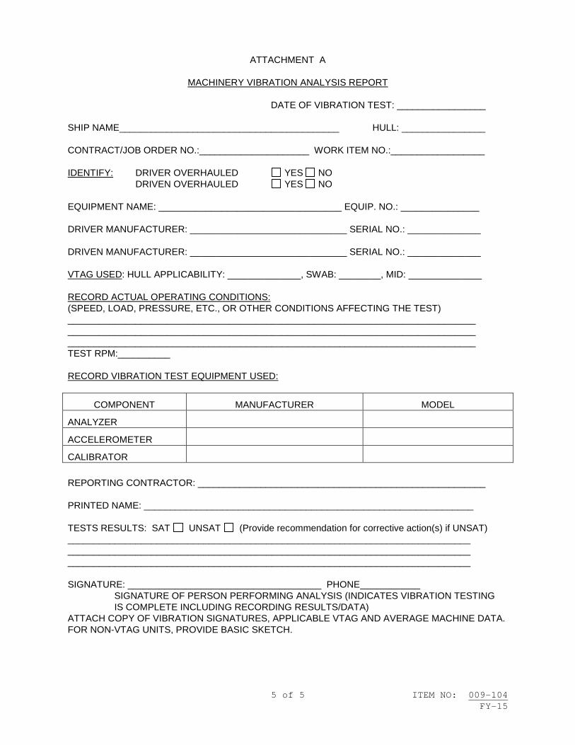
5 of 5 ITEM NO: 009-104 FY-15
ATTACHMENT A
MACHINERY VIBRATION ANALYSIS REPORT
DATE OF VIBRATION TEST: _________________ SHIP NAME__________________________________________ HULL: ________________ CONTRACT/JOB ORDER NO.:_____________________ WORK ITEM NO.:__________________ IDENTIFY: DRIVER OVERHAULED YES NO
DRIVEN OVERHAULED YES NO EQUIPMENT NAME: ___________________________________ EQUIP. NO.: _______________ DRIVER MANUFACTURER: ______________________________ SERIAL NO.: ______________ DRIVEN MANUFACTURER: ______________________________ SERIAL NO.: ______________ VTAG USED: HULL APPLICABILITY: ______________, SWAB: ________, MID: ______________ RECORD ACTUAL OPERATING CONDITIONS: (SPEED, LOAD, PRESSURE, ETC., OR OTHER CONDITIONS AFFECTING THE TEST) ______________________________________________________________________________ ______________________________________________________________________________ ______________________________________________________________________________ TEST RPM:__________ RECORD VIBRATION TEST EQUIPMENT USED:
COMPONENT MANUFACTURER MODEL
ANALYZER
ACCELEROMETER
CALIBRATOR REPORTING CONTRACTOR: _______________________________________________________ PRINTED NAME: _______________________________________________________________ TESTS RESULTS: SAT UNSAT (Provide recommendation for corrective action(s) if UNSAT) _____________________________________________________________________________ _____________________________________________________________________________ _____________________________________________________________________________ SIGNATURE: _____________________________________ PHONE
SIGNATURE OF PERSON PERFORMING ANALYSIS (INDICATES VIBRATION TESTING IS COMPLETE INCLUDING RECORDING RESULTS/DATA)
ATTACH COPY OF VIBRATION SIGNATURES, APPLICABLE VTAG AND AVERAGE MACHINE DATA. FOR NON-VTAG UNITS, PROVIDE BASIC SKETCH.


1 of 1 ITEM NO: 009-105 FY-15
NAVSEA STANDARD ITEM FY-15 ITEM NO: 009-105 DATE: 17 JAN 2013 CATEGORY: II 1. SCOPE: 1.1 Title: Thermal Sprayed Coatings for Machinery Component Repair;
accomplish 2. REFERENCES: 2.1 Standard Items 2.2 MIL-STD-1687, Thermal Spray Processes for Naval Ship Machinery
Applications 2.3 0948-LP-045-7010, Material Control Standard 3. REQUIREMENTS: 3.1 Accomplish the requirements of 2.2 for thermal spray coatings. 3.2 Maintain segregation and record identification markings of Material Identification and Control (MIC) LEVEL I material. Restore LEVEL I markings after coating process in accordance with 2.3. 3.2.1 Accomplish the requirements of 009-27 of 2.1. 4. NOTES: 4.1 None.


1 of 2 ITEM NO: 009-106 FY-15
NAVSEA STANDARD ITEM FY-15 ITEM NO: 009-106 DATE: 06 JAN 2014 CATEGORY: I 1. SCOPE: 1.1 Title: Work Authorization Form Coordinator (WAFCOR); provide 2. REFERENCES: 2.1 Joint Fleet Maintenance Manual (JFMM)
3. REQUIREMENTS: 3.1 Provide a representative whose function is to coordinate the Work Authorization and Control Process, known as the Work Authorization Form (WAF) Coordinator (WAFCOR), from 30 days prior to the actual scheduled start date of shipboard work to the completion of shipboard work. 3.2 The WAFCOR shall be responsible for the work authorization control process for all Repair Activity (RA) work being performed during the contract performance period. The WAFCOR shall receive, process, compare, and coordinate all WAFs and Technical Work Documents (TWDs) submitted by RAs in accordance with the requirements of Volume IV, Chapter 10, of 2.1. The WAFCOR shall meet daily with the designated representatives from each RA, the Commanding Officer's designated representative, and the SUPERVISOR to eliminate any tag-out conflicts, and to advise the SUPERVISOR of any work authorization problems that could impact the RA's or the ship's work operations and testing. 3.2.1 The WAFCOR shall ensure that each RA submits a properly filled out WAF. The WAF/TWD shall show or explain the job description for each work authorization. The WAFCOR shall assign a tracking number and submit the WAF to the Commanding Officer's designated representative. The Commanding Officer's designated representative will determine if adequate isolation and plant/system conditions exist to safely and properly conduct the work, authorize and hang tag-outs, and sign the WAF. Each individual RA must submit work authorizations even if multiple RAs are working on the same components. 3.2.2 The WAFCOR shall legibly sign and release the WAF for start of work upon receipt of legible signature from the cognizant RA's designated representative.
|

2 of 2 ITEM NO: 009-106 FY-15
3.2.3 The WAFCOR shall ensure that the cognizant RAs submit a copy of revisions or changes to the WAF or TWD at the time of revision or change. The WAFCOR will submit all changes to the Commanding Officer's designated representative for processing. Accomplish all applicable verifications required by the original WAF including any tag-out actions. Signatures by all applicable parties shall be reentered on the original WAF or attached sheet. The system tag-outs shall be verified by the Commanding Officer's designated representative and the cognizant RA prior to the accomplishment of the work. 4. NOTES: 4.1 Repair Activity (RA) is any activity (public or private) other than Ship's Force involved in the construction, testing, repair, overhaul, refueling, or maintenance of the ship. Repair Activities include the prime contractor, all subcontractors, government provided contractors or agencies, Alteration Installation Teams, Fleet Maintenance Activities, Naval Shipyards, and others. 4.2 Training requirements are listed in NAVSEA Standard Item 009-24.

1 of 5 ITEM NO: 009-107 FY-15
NAVSEA STANDARD ITEM FY-15 ITEM NO: 009-107 DATE: 17 JAN 2013 CATEGORY: II 1. SCOPE: 1.1 Title: Piping System Cleanliness (Non-Nuclear); accomplish 2. REFERENCES: 2.1 Standard Items 2.2 S9AAO-AB-GOS-010, General Specifications for Overhaul of Surface Ships
(GSO) 2.3 0902-018-2010, General Specifications for Deep Diving SSBN/SSN
Submarines 2.4 S9086-RK-STM-010/CH-505, Piping Systems 2.5 MIL-STD-1330, Precision Cleaning and Testing of Shipboard Oxygen,
Helium, Helium-Oxygen, and Nitrogen Systems 2.6 MIL-STD-419, Cleaning and Protecting Piping, Tubing, and Fittings for
Hydraulic Power Transmission Equipment 2.7 MIL-STD-1622, Cleaning of Shipboard Compressed Air Systems 2.8 S9086-RW-STM-010/CH-516, Refrigeration Systems 3. REQUIREMENTS: 3.1 Accomplish the general cleaning requirements of 2.2 through 2.4 for new, modified, or repaired non-nuclear piping systems and components of nuclear and non-nuclear powered naval vessels. Accomplish the system cleaning requirements of 2.5 through 2.8. 3.1.1 Clean to the following acceptance standard: 3.1.1.1 Cleanliness Level II: Surface shall be visually free of grease, oil, flux, scale, dirt, loose particles and any other contamination foreign to the base metal. Tap water residues on all metals and light superficial rust on carbon steel surfaces, caused by short time exposure to the atmosphere, are permitted. Light dust on cleaned surfaces is not objectionable, provided that the quantity and size of the particle does not adversely affect system operations.

2 of 5 ITEM NO: 009-107 FY-15
3.1.1.2 Cleanliness Level III: Surface shall be reasonably free of contamination and any remaining residue on the surface does not interfere with system operations or damage system components. 3.2 Accomplish local cleaning to areas where existing system cleanliness has been lost in a localized area (such as metal shavings deposited in a pipeline while removing a section for replacement). Restore cleanliness by locally swabbing, wiping, vacuuming, etc., the area to meet existing system cleanliness. (V) “VERIFY CLEANLINESS” 3.2.1 Verify that existing system cleanliness was maintained. 3.3 Accomplish the requirements of 009-09 of 2.1 for cleaning, flushing, and acceptance criteria of compressed air systems in accordance with Section 551 of 2.2 and 2.7. (I)(G) “VERIFY CLEANLINESS” 3.3.1 Verify cleanliness in accordance with acceptance standards. 3.4 Accomplish the requirements of 009-09 of 2.1 for cleaning, flushing, and acceptance criteria of oxygen, nitrogen, and helium systems in accordance with Section 552 of 2.2 and 2.5. (I)(G) “VERIFY CLEANLINESS” 3.4.1 Verify cleanliness in accordance with acceptance standards. 3.5 Accomplish the requirements of 009-09 of 2.1 for cleaning, flushing, and acceptance criteria of hydraulic systems in accordance with Section 556 of 2.2 and 2.6. (I)(G) “VERIFY CLEANLINESS” 3.5.1 Verify cleanliness in accordance with acceptance standards. 3.6 Accomplish the requirements of 009-09 of 2.1 for cleaning, flushing, and acceptance criteria of fuel oil systems in accordance with Section 541 of 2.2. (I)(G) “VERIFY CLEANLINESS” 3.6.1 Verify cleanliness in accordance with acceptance standards. 3.7 Accomplish the requirements of 009-09 of 2.1 for cleaning, flushing, and acceptance criteria of steam systems in accordance with Section 253 of 2.2. (I)(G) “VERIFY CLEANLINESS” 3.7.1 Verify cleanliness in accordance with acceptance standards.

3 of 5 ITEM NO: 009-107 FY-15
3.8 Accomplish the requirements of 009-09 of 2.1 for cleaning, flushing, and acceptance criteria of condensate systems in accordance with Section 255 of 2.2. (I)(G) “VERIFY CLEANLINESS” 3.8.1 Verify cleanliness in accordance with acceptance standards. 3.9 Accomplish the requirements of 009-09 of 2.1 for cleaning, flushing, and acceptance criteria of lube oil systems in accordance with Section 262 of 2.2. (I)(G) “VERIFY CLEANLINESS” 3.9.1 Verify cleanliness in accordance with acceptance standards. 3.10 Accomplish the requirements of 009-09 of 2.1 for cleaning, flushing, and acceptance criteria of fresh and potable water systems in accordance with Section 532 of 2.2. (I)(G) “VERIFY CLEANLINESS” 3.10.1 Verify cleanliness in accordance with acceptance standards. 3.11 Accomplish the requirements of 009-09 of 2.1 for each cleaning operation of refrigerant systems in accordance with the requirements of 2.8. (I)(G) “VERIFY CLEANLINESS” 3.11.1 Verify cleanliness in accordance with acceptance standards. 3.12 Accomplish the requirements of 009-09 of 2.1 for cleaning, flushing, and acceptance criteria of HP/LP steam drains in accordance with Section 534 of 2.2. (I)(G) “VERIFY CLEANLINESS” 3.12.1 Verify cleanliness in accordance with acceptance standards. 4. NOTES: 4.1 This Standard Item does not apply to systems of nuclear-powered ships covered by NAVSEAINST 9210.36, Steam Plant Cleanliness Control, or nuclear piping systems on nuclear-powered ships. 4.2 See Attachment A for Level II and Level III piping systems.

4 of 5 ITEM NO: 009-107 FY-15
ATTACHMENT A CLEANLINESS LEVEL II AND III
CLEANLINESS LEVEL II PIPING SYSTEMS:
• DIVERS AIR (NOTE 1) • ELECTRONICS DISTILLED WATER COOLING (NOTE 1) • HIGH PRESSURE AIR (NOTE 1) • HYDRAULIC PIPING SYSTEMS (NOTE 1) • LUBRICATING OIL SYSTEMS (NOTE 1) • MISSILE HEATING AND COOLING • REFRIGERANT SYSTEM (FREON AND LITHIUM BROMIDE) (NOTE 1) • OXYGEN SYSTEM (NOTE 1) • AIR CONDITIONING CHILLED WATER SYSTEM • AUXILIARY STEAM SYSTEM • CONDENSATE SYSTEM (NOTE 1) • DIESEL FRESHWATER COOLING • AIR FOR DIESEL CONTROL, VITAL AIR, ELECTRONICS SYSTEMS, ABC SYSTEMS AND PNEUMATIC
CONTROL (NOTE 1) • EXHAUST PIPING (STEAM) • FEEDWATER SYSTEM (NOTE 1) • POTABLE WATER SYSTEM (NOTE 1) • FUEL SERVICE SYSTEM (NOTE 1) • DISTILLATE PIPING SYSTEMS • FUEL TRANSFER SYSTEM (NOTE 1) • GASOLINE SYSTEM • HIGH AND LOW PRESSURE DRAIN SYSTEM (NOTE 1) • MAIN STEAM SYSTEM (NOTE 1) • MEDIUM PRESSURE AIR (ABOVE 250 PSI AND BELOW 1500 PSIG) (NOTE 1) • NITROGEN PIPING SYSTEM (NOTE 1) • JP-5 PIPING SYSTEM • OTHER SYSTEMS AS SPECIFIED BY THE DESIGN AGENT
NOTE 1: SEE INDIVIDUAL GSO SECTIONS FOR ADDITIONAL SPECIAL CLEANING REQUIREMENTS CLEANLINESS LEVEL III PIPING SYSTEMS:
• AIR ESCAPE (TANK VENT) • AIR CONDITIONING SEAWATER COOLING SYSTEM • AFFF CONCENTRATE AND AFFF/SW SYSTEMS • AUXILIARY SEAWATER SYSTEM • CO2 SYSTEM

5 of 5 ITEM NO: 009-107 FY-15
• DIESEL EXHAUST SYSTEM • DIESEL SEAWATER COOLING SYSTEM • DISTILLING PLANT, BRINE OVERBOARD DISCHARGE SYSTEM • DISTILLING PLANT, SEAWATER FEED SYSTEM • ESCAPE PIPING (STEAM) • FIREMAIN SYSTEM • HALON • MAIN SEAWATER COOLING SYSTEM • PLUMBING SYSTEM • SANITARY AND FLUSHING PIPING SYSTEM • SHIP SERVICE LOW PRESSURE AIR SYSTEM (NON-VITAL) • OTHER SYSTEMS AS SPECIFIED BY THE DESIGN AGENT


1 of 2 ITEM NO: 009-108 FY-15
NAVSEA STANDARD ITEM FY-15 ITEM NO: 009-108 DATE: 29 JUL 2011 CATEGORY: I 1. SCOPE: 1.1 Title: Aircraft Carrier Requirements for Mooring, Entry to, Movement
within, and Departure from Contractor's Facility; accomplish 2. REFERENCES: 2.1 845-6686999 Rev E, US Navy Vessel Water Depth, Mooring and
Hull/Appendage Clearance Requirements for Transit and Berthing 2.2 DDS 582-1, Design Data Sheet, Calculations for Mooring Systems 2.3 S9086-TW-STM-010/CH-582, Mooring and Towing 2.4 UFC 4-159-03, Mooring Design 3. REQUIREMENTS: 3.1 Channels, berth, and mooring shall comply with 2.1 and 2.2, using 2.3 and 2.4 for guidance. Turning basin shall meet the requirements of 2.1 unless physically impossible, in which case turning area shall meet all other clearance requirements specified in this item. 3.1.1 Minimum water depth shall be maximum draft plus 6 feet minimum at mean low water. List and trim effects shall be considered to determine the 6-feet minimum. 3.1.1.1 The approach channel, vessel turning area, and berth/pier shall be clearly marked with channel markers in areas where the 6-feet minimum does not extend beyond the minimum approach channel, vessel turning area, and berth/pier requirements specified in 2.1. 3.1.1.2 Install temporary fixed reference points at each end of the approach channel and berth. The reference points shall mark the center of the approach channel and berth. 3.1.1.3 The 6-feet minimum shall be for the duration of time at a berth/pier.

2 of 2 ITEM NO: 009-108 FY-15
3.2 Maintain a minimum of 4 feet between the highest point on the ship and overhead projections at mean high water. 3.3 Maintain a minimum horizontal clearance of 17 feet 6 inches between each side of the ship's extreme beam (35 feet total) and any fixed structures such as bridges. 3.4 Submit one legible copy, in approved transferrable media, of a report listing results of the requirements of 3.1 through 3.3 to the SUPERVISOR 15 days prior to availability start date. 4. NOTES: 4.1 This item is for all aircraft carriers for all conditions, including "dead stick" (towed) conditions that enter into a contractor's facility.

1 of 3 ITEM NO: 009-109 FY-15
NAVSEA STANDARD ITEM FY-15 ITEM NO: 009-109 DATE: 29 JUL 2011 CATEGORY: I 1. SCOPE: 1.1 Title: Special Requirements for Non-SUBSAFE Work on SUBSAFE-
Certified Vessels; accomplish 2. REFERENCES: 2.1 0924-LP-062-0010, Submarine Safety (SUBSAFE) Requirements Manual 2.2 0905-LP-485-6010, Control of Testing and Ship Conditioning 2.3 S9510-AB-ATM-010/U, Nuclear Powered Submarine Atmosphere Manual 2.4 Joint Fleet Maintenance Manual (JFMM) 3. REQUIREMENTS: 3.1 Provide a written training plan for accomplishing non-SUBSAFE work on SUBSAFE-certified vessels, using 2.1 through 2.3 and Volume IV, Chapter 10 of 2.4 for guidance. 3.1.1 Submit one legible copy, in approved transferrable media, of the training plan to the SUPERVISOR no later than 15 days prior to availability start date. 3.1.2 Submit revisions to the training plan to the SUPERVISOR for review and acceptance prior to use. 3.1.3 Implement the approved training plan prior to commencement of non-SUBSAFE work on SUBSAFE-certified vessels. 3.2 Train all personnel (including subcontractors) assigned to perform work on SUBSAFE-certified vessels in accordance with the approved training plan of 3.1 prior to start of work. 3.2.1 All personnel shall have direct knowledge of work control procedures, be able to recognize and initiate alarms, be familiar with actions to be taken to evacuate the vessel, and reporting submerged safety draft marks.

2 of 3 ITEM NO: 009-109 FY-15
3.2.2 Submit one legible copy, in approved transferrable media, of a list of qualified contractor and subcontractor personnel to the SUPERVISOR no later than 15 days prior to start of work. The list shall include company name, badge number, and date training was provided, along with certification documentation showing that training requirements have been met. 3.2.2.1 Submit updates to the list as changes occur throughout the availability. 3.3 Accomplish a joint on-site brief and walkthrough of the work site with the SUPERVISOR and the Commanding Officer's designated representative prior to start of work. 3.3.1 Include identification of SUBSAFE components and/or systems located in the area of work, components and/or systems which may be affected by the work, and lessons learned from previous or similar work. Include identification of Unrestricted Operations (URO) Maintenance Requirement (MRC)-related equipment located in the area of work. 3.3.2 Ensure that URO MRC-measured parameter is not violated. (See V-I-5-5.12.1.c of 2.4.) 3.4 Maintain approved written instructions for accomplishing non-SUBSAFE work on the work site at all times. 3.4.1 Do not accomplish work or disturb any system or component without specific approved written instructions for accomplishing non-SUBSAFE work. 3.5 Prohibit the following items from being brought onboard any nuclear-powered vessel or nuclear support vessel: 3.5.1 Any mercury bearing equipment such as mercury thermometers, portable fluorescent lights, black lights or any other items containing mercury. 3.5.2 Nickel-Cadmium fasteners. 3.5.3 Any device that contains a source of radioactivity. 3.5.4 Bright yellow tools, bags, or equipment. 4. NOTES: 4.1 The SUBSAFE program is a certification program implemented by NAVSEA to ensure strict work controls, material controls, and testing to verify submarine system integrity and prevent loss of submarine personnel and equipment.

3 of 3 ITEM NO: 009-109 FY-15
4.2 The URO MRC program was developed by NAVSEA to monitor specific areas of interest to determine if the conditions of these areas are suitable for continued unrestricted operations. 4.2.1 URO MRC Manuals: 4.2.1.1 T9081-AD-MMO-010 & 020 (SSN 21 Class) 4.2.1.2 0924-LP-064-8010 (SSN 688 Class) 4.2.1.3 T0700-AA-PRO-010 (SSBN/SSGN 726 Class) 4.2.1.4 T9081-AE-MMO-010 (SSN 774 Class) 4.2.1.5 0924-LP-040-2010 (NR-1 Only)


1 of 3 ITEM NO: 009-110 FY-15
NAVSEA STANDARD ITEM FY-15 ITEM NO: 009-110 DATE: 29 JUL 2011 CATEGORY: I 1. SCOPE: 1.1 Title: Special Requirements for Non-Nuclear Work on Nuclear Vessels;
accomplish 2. REFERENCES: 2.1 Joint Fleet Maintenance Manual (JFMM)
3. REQUIREMENTS: 3.1 Provide a written training plan for accomplishing non-nuclear work on nuclear vessels, using Volume IV, Chapter 10 of 2.1 for guidance. 3.1.1 Submit one legible copy, in approved transferrable media, of the training plan to the SUPERVISOR no later than 15 days prior to availability start date. 3.1.2 Submit revisions to the training plan to the SUPERVISOR for review and acceptance prior to use. 3.1.3 Implement the approved training plan prior to commencement of non-nuclear work on nuclear vessels. 3.2 Train all personnel (including subcontractors) assigned to perform work on a nuclear vessel in accordance with the approved training plan of 3.1 prior to start of work. 3.2.1 All personnel shall have direct knowledge of work control procedures, be able to recognize and initiate alarms, and be familiar with actions to be taken to evacuate the vessel. 3.2.2 Submit one legible copy, in approved transferrable media, of a list of qualified contractor and subcontractor personnel to the SUPERVISOR no later than 15 days prior to start of work. The list shall include company name, badge number, and date training was provided, along with certification documentation showing that training requirements have been met. 3.2.2.1 Submit updates to the list as changes occur throughout the availability.
2 of 3 ITEM NO: 009-110 FY-15
3.3 Accomplish a joint on-site brief and walkthrough of the work site with the SUPERVISOR and the Commanding Officer's designated representative prior to start of work. 3.3.1 Include identification of all nuclear equipment including nuclear temporary/support systems and radiological containment materials located in the area of work, components and/or systems which may be affected by the work, and lessons learned from previously accomplished or similar work. 3.3.2 Evaluate services/temporary systems to be installed by the contractor that run through spaces containing nuclear equipment for possible leakage/spray protection. 3.3.3 The contractor shall identify all possible contact with nuclear equipment or nuclear temporary/support system identified in the space prior to start of work. 3.3.4 Evaluate the rigging path for potential collateral damage to nuclear components/piping. All inadvertent contact with nuclear equipment or nuclear temporary/support system in the work area during the work shall be brought immediately to the attention of the SUPERVISOR. 3.3.5 Submit one legible copy, in approved transferrable media, of a written report of the requirements of 3.3 to the SUPERVISOR within 24 hours after completion of the briefing and walkthrough. 3.4 Maintain approved written instructions for accomplishing non-nuclear work on the work site at all times. 3.4.1 Do not accomplish work or disturb any system or component without specific approved written instructions for accomplishing work on nuclear vessels. 3.5 Material (permanent or temporary) shall not contact nuclear piping/components unless specifically authorized by the SUPERVISOR. Some examples are cleaning fluid sprays, dripping grease or liquids, inadvertent paint splatter, attaching rope or strings, wood, tape, plastic bags, temporary contractor’s services that contact hot or cold nuclear piping and components. 3.6 Report immediately inadvertent contact with or damage to nuclear equipment regardless of how minor (e.g., gouges, scratches, dents, slag, carbon arc, corrosion) to the SUPERVISOR. 3.7 Prohibit the following items from being brought onboard any nuclear-powered vessel or nuclear support vessel: 3.7.1 Any mercury bearing equipment such as mercury thermometers, portable fluorescent lights, black lights or any other items containing mercury.

3 of 3 ITEM NO: 009-110 FY-15
3.7.2 Nickel-Cadmium fasteners. 3.7.3 Any device that contains a source of radioactivity. 3.7.4 Bright yellow tools, bags, or equipment. 4. NOTES: 4.1 None.


1 of 4 ITEM NO: 009-111 FY-15
NAVSEA STANDARD ITEM FY-15 ITEM NO: 009-111 DATE: 07 NOV 2013 CATEGORY: I 1. SCOPE: 1.1 Title: Schedule and Associated Reports for Availabilities 9 Weeks or
Less in Duration; provide and manage 2. REFERENCES: 2.1 None. 3. REQUIREMENTS: 3.1 For work packages less than 3 weeks in duration, Firm Fixed Price (FFP) or Multi-Ship/Multi-Option (MS/MO), Chief of Naval Operations (CNO), Continuous Maintenance (CM), or Emergency Maintenance (EM) work as determined by the Maintenance Team to be routine or standard repair: Prepare and manage a Production Schedule for each Work Item of the Job order. The Production Schedule shall list: 3.1.1 Start and completion date of the production work for each Work item. 3.1.2 Scheduled start and completion dates of tests. 3.1.3 Critical path and controlling Work Items. 3.1.4 Submit one legible copy, in approved transferrable media, of the Production Schedule to the SUPERVISOR no later than 5 days prior to the availability start date. 3.2 For work packages 3 to 9 weeks in duration, FFP or MS/MO, CNO, CM, or EM work as determined by the Maintenance Team to be routine or standard repair: Prepare and manage a Production Schedule for each Work Item of the Job Order, including milestones identified by the SUPERVISOR. The Production Schedule shall list: 3.2.1 Schedule each Work Item to the activity level listing the start and completion dates for each activity. Each activity shall be displayed to reflect its relevancy to the applicable key events and milestones.

2 of 4 ITEM NO: 009-111 FY-15
3.2.1.1 Assign each activity in the Production Schedule a short title to describe the nature of the activity, system and equipment or machinery involved. Integrate known Alteration Installation Team (AIT), Ship's Force, Commercial Industrial Services (CIS), and Fleet Maintenance Activity (FMA) work. 3.2.1.2 Each activity shall be scheduled by location, system and integrated into the schedule for each activity. 3.2.2 The latest allowable receipt date for contractor and government furnished material to maintain schedule. 3.2.3 Scheduled key events/milestones. 3.2.4 Critical path and controlling Work Items. 3.2.5 Scheduled start and completion dates of tests. 3.2.6 Submit one legible copy, in approved transferrable media, of the Production schedule to the SUPERVISOR no later than 5 days prior to the availability start date. 3.3 Revise Production Schedule weekly to reflect the addition, deletion, or modification of Work Items, and changes made by the contractor for work packages identified in 3.1 and 3.2. 3.3.1 Submit one legible copy, in approved transferrable media, of the revised Production Schedule to the SUPERVISOR one day prior to progress meeting. 3.4 Participate in a weekly progress meeting to be held at a time and place mutually agreeable to all parties for work packages identified in 3.1 and 3.2. 3.4.1 Weekly progress meeting participants shall be prepared to address critical path, controlling work and offer reasonable solutions to problems which may have impact on scheduled milestones or completion date. Interfaces between contractor scheduled and planned AIT or Ship's Force work and Ship's Force actions necessary to support contractor testing and equipment operation schedule shall be discussed. 3.4.2 Provide cognizant management representation to participate in the weekly progress meeting. The representative must be authorized to make management decisions relative to routine requirements of the Job Order which, in good faith, commit the contractor. 3.5 Submit one legible copy, in approved transferrable media, of an availability status report to the SUPERVISOR one working day prior to the weekly progress meeting that includes the revised Production Schedule for work packages identified in 3.2. Submit the following for each Work Item:

3 of 4 ITEM NO: 009-111 FY-15
3.5.1 Percent of production work completed. 3.5.2 Late contractor furnished material. 3.5.3 Late government furnished material. 3.5.4 Late or deficient government furnished information. 3.5.5 A report of overdue contractor condition reports listing Work Item number and expected submission date. The report shall also include those deficiency and condition reports for which government response is outstanding. 3.5.6 Action taken or proposed to resolve problems of 3.5.1 through 3.5.5. 3.6 Coordinate and schedule subcontractor's performance with respect to work progress, material procurement, and AIT, Ship’s Force, CIS, and FMA interface control to support the production schedule for work packages identified in 3.2. 3.6.1 Submit one legible copy, in approved transferrable media, of a complete list of subcontractors by Work Item to the SUPERVISOR at the same time the Production Schedule is submitted. The subcontractor list shall include: 3.6.1.1 Work Item paragraph number. 3.6.1.2 Specific work to be accomplished. 3.6.1.3 Subcontractor's business address. 3.6.2 Submit one legible copy, in approved transferrable media, of a report to the SUPERVISOR of any change to the original list prior to making the change, whenever any subcontractor is added or deleted. 3.7 Accomplish a walk-through with Ship's Force and SUPERVISOR 5 days prior to completion of work in machinery spaces and provide a list of contractor's and Ship's Force work required to be completed prior to light-off for work packages identified in 3.2. 3.7.1 Schedule daily meetings to resolve problems/unfinished work relating to light-off. Meetings shall commence 2 weeks prior to light-off, and continue until completion of testing. 3.7.2 Revise the list of unfinished work, including machinery and systems discrepancies, daily throughout the light-off phase. 3.8 Provide cognizant contractor representation for CNO availabilities to participate in a review conference to be held at the 50-percent point in the availability and a completion conference to be held no later than 3 working

4 of 4 ITEM NO: 009-111 FY-15
days prior to availability completion date to determine the scope of remaining work for work packages identified in 3.2. 3.8.1 Submit one legible copy, in approved transferrable media, of the revised schedule no later than 3 working days prior to the 50-percent review conference. 4. NOTES: 4.1 Definitions. 4.1.1 Production Schedule: The schedule used by contractor and subcontractor personnel as a means of planning, tracking, and coordinating the accomplishment of contract work. 4.1.2 Activity: a portion of an individual Work Item which is a logical subdivision of the Work Item representing a manageable unit of work which must be accomplished at a specific period of time in relation to other activities of the Job Order. 4.1.3 Key Event: An event which cannot slip without impacting or delaying the overall schedule. Key events may be identified by either the contractor or the SUPERVISOR. 4.1.4 Milestone: A significant event identified by the Maintenance Team. Milestones may be identified by either the contractor or the SUPERVISOR. 4.1.5 Critical Path: That sequence of activities which forms the longest duration, and directly affects the completion of the availability. Factors in determining critical path are: time duration required for the activity, space limitations, manpower available, and the interface between Work Item activities. 4.1.6 Controlling Work Items: Those Work Items which are on the critical path of the Job Order and/or those Work Items which, by virtue of scope, material requirements, complexity, or other considerations, have the potential for impact on the scheduled project key events or completion of the availability. 4.1.7 Float: The amount of time an event can be delayed without delaying the start of subsequent or follow-on activities.

1 of 10 ITEM NO: 009-112 FY-15
NAVSEA STANDARD ITEM FY-15 ITEM NO: 009-112 DATE: 29 JUL 2011 CATEGORY: I 1. SCOPE:
1.1 Title: Prevention of Radiographic-Inspection Ionizing-Radiation Hazards; accomplish
2. REFERENCES: 2.1 None. 3. REQUIREMENTS: 3.1 This item applies to all contracts that utilize radiographic inspection as part of their work. “Foreign contractor” refers to a contractor that is contracted from the U.S. Navy host country in which U.S. Navy contracts may be executed onboard U.S. Government property and/or vessels. 3.2 Each foreign contractor shall comply with the regulatory standards of the host country when conducting radiographic inspections on U.S. Government property and/or vessels. 3.3 Fourteen (14) days prior to start of work, submit one legible copy, in hard copy or approved transferrable media, of completed Radiography Operations Planning Work Sheet, Attachment A, to the SUPERVISOR and obtain approval prior to commencement of radiography operations. 3.4 Fourteen (14) days prior to start of work, submit one legible copy, in hard copy or approved transferrable media, of a diagram illustrating the boundary where the exposure rate shall not exceed 2 mr/hr (0.02 mSv/hr) or under special circumstances the dose to an individual in any unrestricted area would not exceed 2 mrem (0.02mSv) in any one hour. In addition, the boundary shall meet the requirement that no individual member of the public will receive a dose in excess of 100 mrem (1mSv)in a calendar year from the radiographic work, exclusive of background radiation. 3.4.1 In addition to the boundary requirements of 3.4, the foreign contractor shall also illustrate the foreign radiation-boundary requirements. 3.5 Establish a physical boundary where the exposure rate is 2mr/hr or less. In some circumstances the boundary may be established at a point where the dose to an individual in any unrestricted area would not exceed 2 mrem in any one hour. The perimeter of the radiation area shall be a physical barrier

2 of 10 ITEM NO: 009-112 FY-15
established by an enclosure or by stanchions and rope, as necessary. Post this boundary with tri-foil radiation warning symbol, “Radiation Area”, “Radiography in Progress”, and “Keep Out” signs written in English and host-country language. The signs shall be visible to any person approaching the radiation area barrier from any accessible direction. 3.5.1 Radiographer shall maintain constant surveillance of the entire area boundary through direct observation or Radiation Safety Officer (RSO)/Radiation Safety Oversight Manager (RSOM) approved positive communication with boundary monitor who is in a position to provide visual surveillance. 3.5.2 Monitor the entire boundary using radiation detection equipment appropriate for the source of radiation during the first radiation exposure of the day. If the beam’s orientation, kVp, mA, collimation, or shielding is changed between exposures, the boundary shall be re-surveyed and re-established in accordance with 3.5, if necessary. 3.5.2.1 Submit one legible copy, in hard copy or approved transferrable media, of a report listing results of the requirements of 3.5.2 within 24 hours. The report shall include Attachment A diagram identifying survey locations, time, date and location of the survey, the highest radiation level recorded, the kVp, mA, and beam direction of the x-ray machine or, if using gamma source material, the half value of the collimator and beam direction at the time of exposure. 3.6 If an unauthorized individual crosses the boundary, the boundary monitor shall immediately notify the radiographer who will immediately stop radiography operations. 3.6.1 Report any boundary violation immediately to the RSO/RSOM via the SUPERVISOR. Submit one legible copy, in hard copy or approved transferrable media, of a follow-up report within 4 hours of the violation, using Boundary Violation Report, Attachment B. The report shall include the time, date of violation, name of individual(s), the names of the radiography crew, including boundary monitor, the kVp, mA, duration of actual exposure and beam direction for the x-ray machine or if using source material, the half value of the collimator and the beam direction at the time of violation. Include a diagram showing the location of the violation and the egress path in relation to the source. 3.7 Upon discovery of loss or theft of radioactive material or x-ray producing devices, the radiographer shall cease and make safe all radiographic operations and immediately notify the RSO/RSOM via the SUPERVISOR. 3.7.1 Report verbally each incident to the SUPERVISOR as soon as management becomes aware of such an event. 3.7.1.1 Submit one legible copy, in approved transferrable media, of a formal written report of the incident within 24 hours.

3 of 10 ITEM NO: 009-112 FY-15
4. NOTES: 4.1 The SUPERVISOR shall perform oversight and surveillance of all radiography operations on U.S. Government property and/or vessels associated with contracted work. 4.2 The technical point of contact for the requirements contained in this Standard Item is SUPERVISOR’s RSO or RSOM for radiographic inspections conducted in the host-country and any U.S. Government Detachment. 4.3 This Standard Item complies with 10 CFR Parts 19, 20, and 34 and 29 CFR 1910.1096.

4 of 10 ITEM NO: 009-112 FY-15
ATTACHMENT A
RADIOGRAPHY OPERATIONS PLANNING WORK SHEET
A. General Information 1. Prime Contractor Name: 2. Subcontractor Name (if applicable): 3. Proposed Date(s) and Time(s) of Planned Radiography: 4. Purpose of Radiographic Operation: 5. Host country regulatory standards applicable to radiographic
inspections preferably translated to English. B. If conducting gamma radiography complete the following: 1. Radioisotope: Serial Number: 2. Activity: Date of Determination of Activity: 3. Collimator Serial Number: 4. Half Value Thickness: 5. Transportation and vehicle information: a. Manufacturer: b. Model: c. License Plate Number: d. Sign on Vehicle: e. Driver’s Name: f. Passengers: g. Location of radiography operation site (ship, submarine, building,
pier):

5 of 10 ITEM NO: 009-112 FY-15
h. Transportation route to be taken to and from work site while on Government activity:
C. If conducting x-ray radiography complete the following: 1. Machine Manufacturer: 2. Serial Number: 3. Maximum kVp: 4. Maximum mA: 5. Total Number of Exposures: 6. Direction of Beam: D. Provide a diagram of each work site that illustrates: 1. Each location of the radiography, including major features such as
walls, bulkheads, tanks, walkways or passageways that may provide shielding or difficulty in controlling the area.
2. The location of the exposure device drive cable, guide tube, and end
stop if using gamma radiography equipment, or the location of the tube head and control panel if conducting x-ray radiography.
3. The location of the 2 mr/hr (0.02 mSv/hr) controlled boundary. E. Provide the calculations for the 2 mr/hr (0.02 mSv/hr) controlled boundary
from the distance from the gamma radiography source, or the x-ray machine tube head, to the location where the boundary shall be established.
F. Review/Approval:

6 of 10 ITEM NO: 009-112 FY-15
Contractor’s Radiographer:
Name (Printed) Signature
Date:
RSO/RSOM (SUPERVISOR’s) Approval: Name (Printed) Signature
Date:

ATTACHMENT B FOR OFFICIAL USE ONLY
7 of 10 ITEM NO: 009-112
FY-15
0BBOUNDARY VIOLATION REPORT Report #
NAME OF REPORTING INDIVIDUAL: TIME/DATE OF THE VIOLATION: LOCATION OF THE VIOLATION:
COMPANY: SUPERVISOR:
EQUIPMENT INVOLVED FOR GAMMA RADIOGRAPHY: ISOTOPE: ACTIVITY: HALF VALUE OF THE COLLIMATOR: DURATION OF EXPOSURE:
FOR X-RAY RADIOGRAPHY mA: kVp: DURATION OF EXPOSURE:
WORK ITEM NUMBER:
CONTRACT NUMBER:
INDIVIDUALS WHO VIOLATED THE BOUNDARY NAME(S) DEPT. ORGANIZATION/COMPANY
NAMES OF THE RADIOGRAPHY CREW MEMBERS, INCLUDING NAMES OF BOUNDARY MONITORS
NAME(S) DEPT. COMPANY
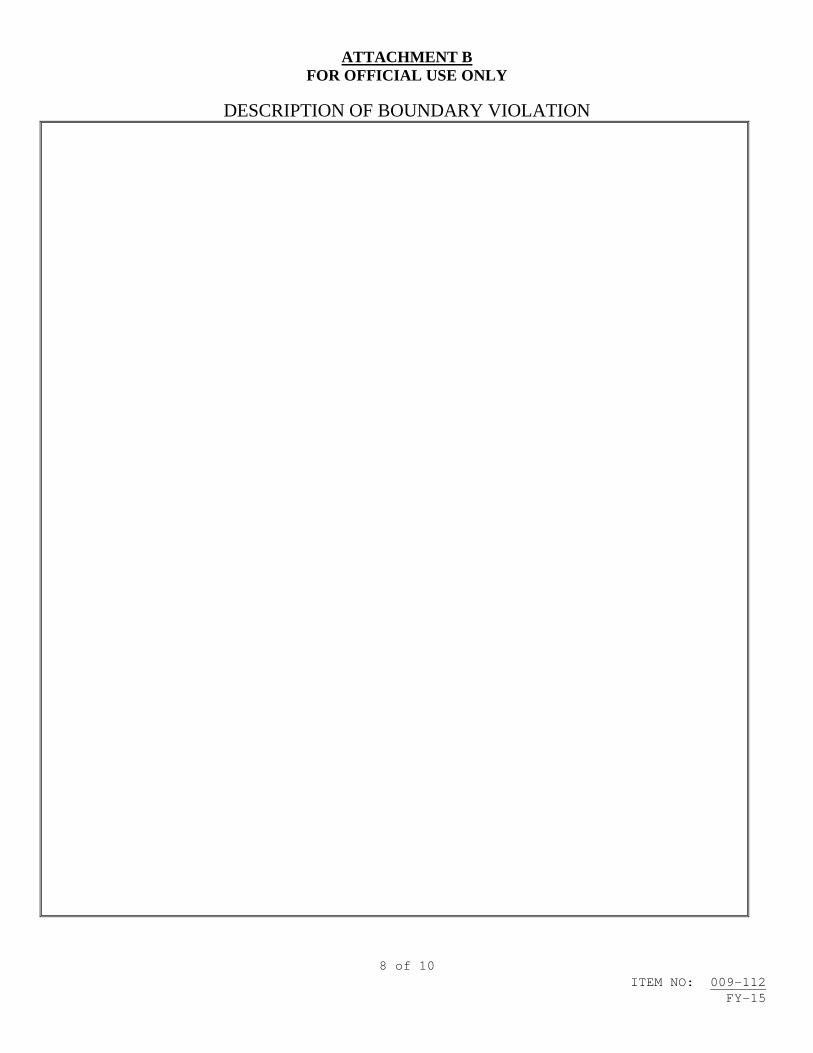
ATTACHMENT B FOR OFFICIAL USE ONLY
8 of 10 ITEM NO: 009-112
FY-15
DESCRIPTION OF BOUNDARY VIOLATION

ATTACHMENT B FOR OFFICIAL USE ONLY
9 of 10 ITEM NO: 009-112
FY-15
DIAGRAM SHOWING THE LOCATION OF THE VIOLATION AND THE EGRESS PATH IN RELATION TO THE SOURCE
SIGNATURE OF REPORTING INDIVIDUAL: DATE:

ATTACHMENT B FOR OFFICIAL USE ONLY
10 of 10 ITEM NO: 009-112
FY-15
Incident Report Instructions
REPORT NUMBER- Unique tracking number created by contractor NAME OF REPORTING INDIVIDUAL: – Self Explanatory DATE/TIME OF THE VIOLATION: – Self Explanatory LOCATION OF THE VIOLATION: – Base/Yard, Ship name and hull number, space number and compartment name COMPANY: – Prime and subcontractors involved SUPERVISOR – Supervisor of employee(s) involved EQUIPMENT INVOLVED – Self Explanatory WORK ITEM NUMBER – Work Item being accomplished when incident occurred CONTRACT NUMBER: – Contract Number assigned by government agency i.e. RMC, AIT Sponsor. INDIVIDUALS WHO VIOLATED THE BOUNDARY: – Name, Department and Organization/Company of individuals that violated the boundary. NAMES OF THE RADIOGRAPHY CREW MEMBERS, INCLUDING NAMES OF BOUNDARY MONITORS: – Name, Department and Company of the members of the radiography crew, including names of boundary monitors. DESCRIPTION OF BOUNDARY VIOLATION: – Narrative description of the boundary violation including the sequence of events, time line, estimated exposures to individuals who violated the boundary, the immediate corrective actions taken to secure operations and emergency notifications that were made. DIAGRAM SHOWING THE LOCATION OF THE VIOLATION AND THE EGRESS PATH IN RELATION TO THE SOURCE: – A diagram of the location of the boundary violation showing the egress path and location of the individual(s) that violated the boundary, location of the source, beam direction (for x-ray machine radiography or gamma radiography if collimator was used) and the location of any barriers, walls, or equipment that would provide shielding. SIGNATURE OF REPORTING INDIVIDUAL: – Self Explanatory. TITLE – Self Explanatory. DATE – Self Explanatory.

1 of 13 ITEM NO: 009-113 FY-15
NAVSEA STANDARD ITEM FY-15 ITEM NO: 009-113 DATE: 07 NOV 2013 CATEGORY: II 1. SCOPE: 1.1 Title: Rotating Electrical Equipment with Sealed Insulation Systems (SIS); rewind 2. REFERENCES: 2.1 Standard Items 2.2 MIL-STD-2037, Procedure to Obtain Certification for Electric Motor Sealed Insulation Systems 2.3 Equipment Technical Manual 2.4 S9086-KC-STM-010/CH-300, Electric Plant - General 2.5 S9086-KE-STM-010/CH-302, Electric Motors and Controllers 2.6 S9086-KN-STM-010/CH-310, Electric Power Generators and Conversion
Equipment 2.7 S9086-HN-STM-010/CH-244, Propulsion Bearings and Seals 2.8 S6260-BJ-GTP-010, Electrical Machinery Repair, Electric Motor,
Shop Procedures Manual 2.9 MIL-STD-1310, Shipboard Bonding, Grounding, and Other Techniques for
Electromagnetic Compatibility and Safety 3. REQUIREMENTS: 3.1 Only Repair Activities certified by Naval Sea Systems Command (NAVSEA) in accordance with 2.2 may rewind motors with a Sealed Insulation System. 3.1.1 Submit one legible copy, in hard copy or approved transferrable media of the NAVSEA Certification Recertification letter confirming the Repair Activity has fulfilled the requirements for the Sealed Insulation System process. The NAVSEA letter shall indicate the type of motors and the range of motor frame sizes the activity is qualified to rewind.

2 of 13 ITEM NO: 009-113 FY-15
3.1.2 Submit any change of certification as it occurs to the SUPERVISOR. 3.2 Submit one legible copy, in hard copy or approved transferrable media of any deviations between the NAVSEA-approved Repair Activity SIS Rewind Procedure (SISRP) and this Standard Item for record purposes. 3.3 Prior to disconnecting equipment: 3.3.1 Record and retain electrical hook-up data. Record and retain air gap readings. Record and retain bearing clearances for sleeve bearing equipment only. 3.3.2 Inspect couplings for cracks, broken segments, wear, and misalignment in excess of tolerances specified in 2.3. 3.3.3 Disconnect the equipment electrically and mechanically, using 2.3 for guidance. 3.3.3.1 Matchmark, identify, and retain chocks, shims, shock mounts, sound damping pads, and other accessories associated with equipment. 3.3.3.2 Record shaft thrust and run out readings. 3.4 Remove equipment including rotating components connected directly to the shaft. 3.4.1 Remove entire vaneaxial and tubeaxial fan assemblies from the duct system and transport to the shop for repair. 3.5 Inspect foundations for cracks, areas of distortion, and deterioration in excess of 25 percent of the thickness of each member of the structure. 3.6 Submit one legible copy, in approved transferrable media, of a report listing inspection results, missing parts, defective parts, and measurements taken in 3.3 and 3.5 to the SUPERVISOR. 3.7 Matchmark, disassemble and inspect the equipment removed in 3.4, in accordance with the Repair Activity SISRP, using 2.3 through 2.8 for guidance. 3.7.1 Accomplish a core loss test prior to winding removal in accordance with the Repair Activity SISRP. Record data. 3.7.1.1 Conduct a loop test in accordance with Paragraphs 5.1.2.3.3(a) (1) through (16) or 5.1.2.3.3(b) (1) through (12) as applicable of 2.2 when core indicates a marginal satisfactory reading or when test equipment does not directly support equipment being subjected to testing. 3.7.1.2 Inspect for hot spots in accordance with the Core Loss Tester Instruction Manual.

3 of 13 ITEM NO: 009-113 FY-15
3.7.2 Remove each winding, in accordance with the Repair Activity SISRP for winding removal and 2.8 for core inspection. 3.7.2.1 Verify the temperature limitations of the core material prior to exercising the burnout oven option. The surface temperature of the laminated iron surface shall be determined by thermocouple and shall not exceed 370 degrees Centigrade (698 degrees Fahrenheit). 3.7.2.2 Record winding data. Verify conformance of recorded data to the manufacturer's winding data. 3.7.2.3 Accomplish a core loss test after winding removal in accordance with the Repair Activity SISRP. Record data. 3.7.2.4 Conduct a loop test in accordance with Paragraphs 5.1.2.3.3(a) (1) through (16) or 5.1.2.3.3(b) (1) through (12) as applicable of 2.2 when core indicates a marginal satisfactory reading or when test equipment does not directly support equipment being subjected to testing. 3.7.2.5 Inspect for hot spots in accordance with the Core Loss Tester Instruction Manual. 3.7.2.6 Dip core for preservation in accordance with the Repair Activity SISRP. 3.7.3 Protect machined surfaces. Accomplish the requirements of 009-32 of 2.1, including Table 5, Line 10, for the equipment housing exterior, fan(s), and interior and exterior of end bells. 3.8 Inspect rotors for cracked bars, localized overheating, rubbing, insulation damage, and burns/hot spots. Record data. 3.9 Inspect and dimensionally measure end bells, frame, rabbet fits, shaft, sleeve and pedestal bearings, keyways, fan and running surfaces for wear, eccentricity, and other defects, using 2.3 for accept or reject criteria, and 2.7 for location and type of measurements to be taken. Record data. 3.10 Submit one legible copy, in approved transferrable media, of a report listing results of the requirements of 3.7 through 3.9 to the SUPERVISOR. 3.11 Rewind the equipment in accordance with the Repair Activity SISRP and the Original Equipment Manufacturer's (OEM) "for Navy use" winding data. 3.11.1 Do not permanently connect winding until after successful completion of testing of 3.11.3 through 3.11.7. 3.11.2 Material shall be in accordance with the Repair Activity SISRP.

4 of 13 ITEM NO: 009-113 FY-15
3.11.2.1 New temperature detectors shall be in accordance with 2.3. (V) "INSULATION RESISTANCE TEST" 3.11.3 Accomplish 500-volt megger insulation resistance test in accordance with the Repair Activity SISRP. (V) "DC RESISTANCE TEST" 3.11.4 Accomplish a DC resistance test of windings, using a Wheatstone or Kelvin bridge, or with an ohmmeter capable of resolving one milliohm (0.001 ohm) in accordance with the Repair Activity SISRP. Record phase balance for multi-phase equipment. (V) "VOLTAGE SURGE TEST" 3.11.5 Accomplish a voltage surge test in accordance with the Repair Activity SISRP. (V) "DC HI POT TEST" 3.11.6 Accomplish a DC HI POT test in accordance with the Repair Activity SISRP. 3.11.7 Accomplish 500-volt megger insulation resistance test in accordance with the Repair Activity SISRP. 3.12 Permanently connect the windings. 3.12.1 Repeat tests described in 3.11.3 through 3.11.7. (V) "VARNISH TEMPERATURE, VISCOSITY, AND GEL TIME TESTS" 3.13 Select varnish methods and material in accordance with the Repair Activity SISRP. 3.13.1 Maintain the varnish in accordance with the Repair Activity SISRP and the varnish manufacturer's instructions. 3.13.2 Maintain a current revision of the varnish manufacturer's instructions on storage, maintenance, and use of the type of varnish to be applied. 3.13.3 Maintain a record, in accordance with the Repair Activity SISRP, of varnish temperature, viscosity, and, for solventless varnish, gel time tests. Tests must show varnish is within varnish manufacturer's recommendations and have been accomplished in the intervals specified by the varnish manufacturer. The record must also show the varnish is being stored as recommended by the varnish manufacturer.

5 of 13 ITEM NO: 009-113 FY-15
3.14 Insulate the windings using the Vacuum Pressure Impregnation (VPI) procedure in accordance with the Repair Activity SISRP. 3.14.1 Do not immerse the leads. 3.14.2 Wipe surfaces that affect assembly such as rabbet fits and mounting flanges with a cloth moistened with a solvent after draining and before baking. 3.15 Remove excess varnish runoff from the component locations described in 3.14.2 after final baking. 3.16 Prime equipment housing, fan(s), and end bells with one coat F-84 Alkyd Zinc Molybdate TT-P-645 (1.5 mils dry film thickness). 3.17 Submerge wound assembly in fresh water for 24 hours. 3.18 Accomplish a Submerged Insulation test in accordance with the Repair Activity SISRP. Record data. 3.19 Accomplish a 500-volt megger dry insulation resistance test in accordance with the Repair Activity SISRP. Record data. 3.20 Accomplish an AC HI POT test in accordance with the Repair Activity SISRP. Record data. 3.21 Accomplish a Surge Comparison test in accordance with the Repair Activity SISRP. Record data. 3.22 Accomplish a 500-volt megger dry insulation resistance test in accordance with the Repair Activity SISRP. Record data. 3.23 Measure resistance value of each winding temperature detector, using a low voltage ohmmeter. Record data. 3.24 Submit one legible copy, in approved transferrable media, of a report listing results of the requirements of 3.18 through 3.23 to the SUPERVISOR. 3.25 Accomplish the requirements of 009-15 of 2.1 for each rotating assembly. 3.26 Install identification markers on wiring in the external connection box. 3.26.1 Markers shall be aluminum wrap-around type with metal stamped or embossed markings. 3.27 Repair lightly scored areas of frame, end bells, and shaft by manual methods. Recondition threads and fit key to keyway. Step keys shall not be used.

6 of 13 ITEM NO: 009-113 FY-15
3.27.1 Apply a thin coat of petrolatum to unpainted mating surfaces except for explosion-proof motors that shall have clean, dry mating surfaces. 3.28 Prepare and refinish equipment. Protect machine surfaces, windings, and nameplates from being painted or otherwise damaged. 3.28.1 Accomplish the requirements of 009-32 of 2.1, including Table 5, Line 10, for each housing, fan, and interior and exterior of each end bell. 3.29 Accomplish the requirements of 009-32 of 2.1 for the foundations of the equipment removed in 3.4. 3.30 Accomplish the following on equipment having other than sleeve-type bearings unless otherwise specified in the invoking Work Item, using 2.8 for guidance. 3.30.1 Except as indicated in 3.30.1.1 (utilizing Attachment A for guidance), install new bearings, seals, fittings, lock washers, and locknuts conforming to 2.3, using 2.7 and Chapter 6 of 2.8 for guidance. 3.30.1.1 Install Type 111, Class 8 (double seal) bearings in motors meeting the criteria identified in Chapter 6 of 2.8. Only double seal bearings identified in Chapter 6 of 2.8 are acceptable for this use. 3.30.1.2 For vaneaxial and tubeaxial fan motors not meeting the criteria of Chapter 6 of 2.8, if not originally furnished or already accomplished during previous repair, install Type 111, Class 8 (double seal) bearings with a C3 (greater than normal) radial internal clearance in place of the Type 111 bearing originally furnished. Install Type 120 bearings in vaneaxial and tubeaxial fan motors originally furnished with Type 120 bearings. 3.30.1.3 Install new label plates with the inscription "DO NOT LUBRICATE" on equipment using double seal bearings (Type 111, Class 8 or Type 120). 3.30.1.4 For equipment converted from re-lubricable bearings to double seal bearings, install pipe plugs on all grease fills and drains. 3.30.1.5 For equipment converted from lubricated bearings to double seal bearings, submit one legible copy, in approved transferrable media, of a report that reflects the change in the maintenance requirements for the converted motor. 3.30.2 For equipment not using double seal bearings, lubricate bearings with grease conforming to DOD-G-24508 as required in Paragraphs 244-1.7.7.2 and 244-1.7.7.3 of 2.7. 3.31 Assemble the equipment disassembled in 3.7, using 2.3 through 2.8 for guidance.

7 of 13 ITEM NO: 009-113 FY-15
3.31.1 Do not use materials containing silicone in the repair and reassembly of equipment with commutator or collector rings. 3.31.2 Install new fasteners conforming to MIL-DTL-1222, Type I or II, Grade 5, zinc coated. 3.31.3 Fasteners requiring a permeability factor of 2.0 or less shall conform to Grade 304 CRES. 3.31.4 Install new gaskets on covers, inspection plates, and between the external connection box and the frame. Gaskets shall conform to MIL-PRF-1149 unless otherwise specified in 2.3. 3.31.5 Adjust air gap as specified in 2.3, plus or minus 10 percent. 3.31.6 Rotate shaft by hand a minimum of 3 revolutions. Rubbing or binding of rotating assembly not allowed. 3.31.7 Install label plates conforming to MIL-DTL-15024 for those found to be missing or damaged. (V) "NO-LOAD SHOP TEST" 3.32 Accomplish a no-load shop test of the motor for a minimum of one-half hour. 3.32.1 Verify proper direction of rotation. 3.32.2 After one-half hour, record current and voltage in each phase, speed and bearing temperature rise measured on the equipment's exterior near each bearing. 3.32.3 Submit one legible copy, in approved transferrable media, of the recorded data to the SUPERVISOR. (V) "OPERATIONAL SHOP TEST (FOR VANEAXIAL/TUBEAXIAL FANS - ASSEMBLY COMPLETELY REASSEMBLED)" 3.33 With the vaneaxial/tube axial fan reassembled, accomplish an operational test for one hour after bearing and stator temperatures stabilize within 1 degree C for three consecutive 15-minute intervals. 3.33.1 Verify proper direction of rotation. 3.33.2 Record current, voltage, frame and bearing temperature rise and speed at 15-minute intervals. 3.33.2.1 Bearing temperatures shall not exceed 180 degrees Fahrenheit, unless otherwise specified in the invoking Work Item or equipment technical manual.

8 of 13 ITEM NO: 009-113 FY-15
3.33.3 Measure and record hot insulation resistances of winding to ground immediately upon completion of the operational shop test, using a 500-volt megger. 3.33.4 Submit one legible copy, in approved transferrable media, of the recorded data to the SUPERVISOR. 3.34 Install equipment removed in 3.4. 3.34.1 Remove existing and install new foundation fasteners conforming to MIL-DTL-1222, Type I or II, Grade 5, zinc coated, and self-locking hexagon nuts conforming to NASM-25027, excluding body-fitted bolts and studs. 3.34.2 Remove existing galled or distorted body-fitted bolts and studs and install new fitted bolts and studs conforming to MIL-DTL-1222, Type I, Grade 5. 3.34.3 Fasteners, body-fitted bolts, and studs requiring a permeability factor of 2.0 or less shall conform to Grade 304 CRES. 3.34.4 Align equipment in accordance with 2.3. Measure and record facial and peripheral coupling data. 3.34.4.1 Install chocks, shims, shock mounts, and sound damping pads. 3.34.4.2 Accomplish the requirements of 009-58 of 2.1 for driver and pump shafts. 3.34.5 Connect electrical cables to equipment, using data retained in 3.3.1. 3.34.6 Bond and ground equipment in accordance with 2.9, using new ground straps. 3.34.7 Rotate shaft by hand a minimum of 3 revolutions. Rubbing or binding of rotating assembly not allowed. 3.34.8 Measure and record the air gap and bearing clearance (sleeve bearing equipment only), insulation resistance (at 500 volts DC), and thrust. (V)(G) "OPERATIONAL TEST" 3.35 Accomplish an operational test of the assembled equipment at full system capacity for one hour after bearing and stator temperatures stabilize within 1 degree C for three consecutive 15 minute intervals, unless otherwise specified in the invoking Work Item. 3.35.1 Verify proper direction of rotation.

9 of 13 ITEM NO: 009-113 FY-15
3.35.2 Record current, voltage, frame and bearing temperature rise, and speed at 15-minute intervals. Frame and bearing temperature rise and speed is not required for vaneaxial and tubeaxial fan assemblies. 3.35.2.1 Bearing temperatures shall not exceed 180 degrees Fahrenheit unless otherwise specified in the invoking Work Item/equipment technical manual. 3.35.3 Measure and record hot insulation resistances of windings to ground immediately upon completion of test, using a 500-volt megger. 3.36 Submit one legible copy, in hard copy or approved transferrable media, of a report listing data recorded in 3.34.4, 3.34.8, 3.35.2, and 3.35.3 to the SUPERVISOR. 4. NOTES: 4.1 This Standard Item is concerned primarily with the requirements to rewind rotating electrical equipment with a sealed insulation system in accordance with 2.2. Each Certified Repair Activity has developed a SIS Rewind Procedure (SISRP) that has been reviewed, approved by and filed with NAVSEA. In most cases, these Repair Activity SISRPs are treated as proprietary and may not be available to the SUPERVISOR for process review. The NAVSEA approved Repair Activity SISRP is the guiding document by which the equipment is to be rewound and supersedes any specification detailed in this Standard Item. 4.2 Equipment technical manual, Allowance Parts List (APL) (if applicable) and drawings will be listed in the invoking Work Item. 4.3 Shop test of generator will be addressed in the invoking Work Item. 4.4 The use of silicone is not allowed on any rotating electrical machinery containing brushes. 4.5 For the current list of NAVSEA-certified facilities for Vacuum Pressure Insulation (VPI) Sealed Insulation Systems, contact Naval Surface Warfare Center Carderock Division, Department 934, Phone (215) 897-7245. 4.6 Utilize Attachment A for determination if the Navy’s motor bearing conversion program for Extended Life Double Seal (ELDS) ball bearings is permissible. 4.7 MIL-B-17931 (Bearings, Ball, Annular, For Quiet Operation) bearings are considered to be Long Lead Time (LLT) material. It is recommended these bearings be provided as Government Furnished Material (GFM). 4.8 Data received in 3.30.1.5 shall be forwarded to the local Naval Supervisory Authority (NSA) logistics representative for the purpose of initiating action ensuring shipboard databases such as the Equipment Guidance List (EGL) are updated to reflect the change in maintenance requirements for

10 of 13 ITEM NO: 009-113 FY-15
converted motors. Additionally, where APL changes are initiated to convert to ELDS bearings, a COSAL feedback report shall be submitted, providing the NSN and part number for the ELDS bearing by the NSA logistics representative. Utilize the following website to initiate changes to Technical Manuals, APLs, etc.: http://www.navy311.navy.mil.

11 of 13 ITEM NO: 009-113 FY-15
ATTACHMENT A
1. To reduce motor maintenance and repair costs, the NAVY has implemented a program that allows for the use of Extended Life Double Seal (ELDS) bearings.
2. LIMITATIONS: The ELDS program does NOT apply to motors that are under the cognizance of NAVSEA 08.
3. APLs for motors meeting the conversion criteria requirements have been modified to identify ELDS bearings. In these cases, the APL bearing criteria will override any specifications delineated in the equipment technical manual or the motor "Original Equipment Manufacturer (OEM)" drawings. If ELDS bearings are not indicated in an APL, the following motor criteria must meet the applicability specifications for motors to undergo conversion to ELDS bearings:
3.a Motor must be installed on a surface ship and must NOT be under the cognizance of NAVSEA 08.
3.b Commercial motors are not eligible. Motors must have been furnished to the NAVY in accordance with MIL-DTL-17060 (Motors, Alternating Current, Integral Horsepower, Shipboard use), MIL-M-17413 (Motors, Direct Current, Integral H.P., Naval Shipboard [NAVY]) or MIL-M-17059 (Motors, 60 Cycle, Alternating Current Fractional H.P. [Shipboard Use]).
3.c Motors using one or more noise-quiet bearings per MIL-B-17931 (Bearings, Ball, Annular, For Quiet Operation) are NOT eligible for ELDS conversion.
3.d Bearings originally furnished with the motor must be type 111 bearings per FF-B-171. Motors are NOT to be considered as candidates for ELDS conversion in situations where the equipment technical manual and/or the OEM motor drawings originally specified FF-B-171 bearings but have notes indicating that replacement bearings are to be in accordance with MIL-B-17931 (Bearings, Ball, Annular, For Quiet Operation).
3.e The use of ELDS bearings is limited to motors where the full load speed and the size of both bearings are as follows:
1. Maximum bearing size 306 or 206 and full load rpm between 1,801 and 3,600 rpm.
2. Maximum bearing size 313 or 213 and full load rpm between 1,201 and 1,800 rpm.
3. Maximum bearing size 318 or 218 and full load rpm less than 1200 rpm.
4. The repair process using ELDS bearings includes the following requirements:

12 of 13 ITEM NO: 009-113 FY-15
4.a Only ELDS bearings, in accordance with the following table (Attachment A / Table 1), can be used. Other double seal bearings will not provide an acceptable bearing life.
Attachment A / Table 1
ELDS Bearings NSNs and Part Numbers
SIZE P/N NSN
201 6201-2RS1C3/GHY 3110-01-492-0221
202 6202-2RS1C3/GHY 3110-01-491-0233
203 6203-2RS1C3/GHY 3110-01-491-0234
204 6204-2RS1C3/GHY 3110-01-491-6636
205 6205-2RS1C3/GHY 3110-01-451-9166
206 6206-2RS1C3/GHY 3110-01-451-9165
207 6207-2RS1C3/GHY 3110-01-451-9164
208 6208-2RS1C3/GHY 3110-01-451-9170
209 6209-2RS1C3/GHY 3110-01-451-9252
210 6210-2RS1C3/GHY 3110-01-492-1831
211 6211-2RS1C3/GHY 3110-01-518-0937
303 6303-2RS1C3/GHY 3110-01-493-3750
304 6304-2RS1C3/GHY 3110-01-451-9153
305 6305-2RS1C3/GHY 3110-01-451-9158
306 6306-2RS1C3/GHY 3110-01-451-9159
607 6307-2RS1C3/GHY 3110-01-451-9161
308 6308-2RS1C3/GHY 3110-01-451-9167
309 6309-2RS1C3/GHY 3110-01-451-9168

13 of 13 ITEM NO: 009-113 FY-15
310 6310-2RS1C3/GHY 3110-01-490-6683
311 6311-2RS1C3/GHY 3110-01-492-0223
312 6312-2RS1C3/GHY 3110-01-490-6848
313 6313-2RS1C3/GHY 3110-01-492-0191
314 6314-2RS1C3GHY 3110-01-492-0226
315 6315-2RS1C3/GHY 3110-01-494-0993
316 6316-2RS1C3/GHY 3110-01-492-0188
317 6317-2RS1C3/GHY 3110-01-492-0219
318 6318-2RS1C3/GHY 3110-01-493-3749
4.b Both bearings of each converted motor must be ELDS bearings.
4.c A label plate must be permanently attached to the motor indicating "Do Not Lubricate".
4.d Grease fills and drains, if present, must be fitted with a pipe plug, securely fastened. Fittings to accommodate grease guns must be replaced with pipe plugs."


1 of 3 ITEM NO: 009-114 FY-15
NAVSEA STANDARD ITEM FY-15 ITEM NO: 009-114 DATE: 07 NOV 2013 CATEGORY: II 1. SCOPE: 1.1 Title: Mold Remediation; accomplish 2. REFERENCES:
2.1 EPA 402-K-01-001, Mold Remediation in Schools and Commercial Buildings
2.2 29 CFR Part 1915, Occupational Safety and Health Standards for
Shipyard Employment 3. REQUIREMENTS: 3.1 Conduct and document an initial determination of potential personnel exposure to materials contaminated with mold or mold spores prior to the start of work. 3.1.1 Provide a copy of the documentation, signed by a Competent Person as defined in 29 CFR 1915.4, to the SUPERVISOR upon request. 3.2 Ensure the remediation of material contaminated with mold or mold spores meets the guidance provided in 2.1. 3.3 Provide a notice and remediation plan to the SUPERVISOR and to the Commanding Officer's designated representative prior to start of work. 3.3.1 The remediation plan shall be on the job site and include at a minimum the following information: 3.3.1.1 Scope and location of the remediation area. 3.3.1.2 Method(s) to be used to remediate material contaminated with mold or mold spores. 3.3.1.3 List of Personal Protective Equipment (PPE) in accordance with 2.2 to be used during remediation process.

2 of 3 ITEM NO: 009-114 FY-15
3.3.1.4 Engineering controls (i.e., ventilation and containment) to be used to eliminate exposure to personnel and other spaces/compartments. 3.3.2 Post a notice at the ship's Quarterdeck and at all entrances to the work areas for each job or separate area of potential exposure to mold or mold spore remediation operations at least 4 hours, but not more than 24 hours, prior to the start of work. 3.3.3 The notice shall contain the following information: 3.3.3.1 Ship's name and hull number 3.3.3.2 Work Item number 3.3.3.3 Compartment or frame number 3.3.3.4 Identification of hazard 3.3.3.5 Date and time of work process 3.3.3.6 Identification of engineering and work practice controls 3.3.4 Deliver notification of work planned over a weekend or Monday following that weekend to the Commanding Officer's designated representative not later than 0900 on the Friday immediately preceding that weekend. 3.3.5 Deliver notification of work planned on a Federal holiday and on the day following the Federal holiday to the Commanding Officer's designated representative not later than 0900 on the last working day preceding the Federal holiday. 3.3.6 The notice and remediation plan shall be submitted to the SUPERVISOR for review prior to commencement of the work operation. Authorization of the SUPERVISOR shall be obtained before proceeding with the work. 3.4 Provide for isolation and blanking of ship's ventilation systems in work areas to prevent mold or mold spore contamination of ventilation systems or other compartments/spaces. 3.5 Post warning signs and establish regulated areas for monitoring and authorized personnel entry. 3.6 Visually monitor the affected areas during work operations to ensure compliance with 2.1 and 2.2. Monitoring shall include adjacent spaces to ensure the work area containments and work practices are effective. Results of surveillance shall be documented and documentation shall be made available to the SUPERVISOR.
3 of 3 ITEM NO: 009-114 FY-15
(V)(G) “FINAL INSPECTION” 3.7 Conduct a final visual inspection jointly with the SUPERVISOR and Commanding Officer’s designated representative to verify that all visible mold and mold-damaged materials have been removed. 4. NOTES: 4.1 Reference 2.1 is available at http://www.epa.gov/mold/mold_remediation.html


1 of 2 ITEM NO: 009-115 FY-15
NAVSEA STANDARD ITEM
FY-15 ITEM NO: 009-115 __ DATE: 07 NOV 2013 CATEGORY: II_____ 1. SCOPE: 1.1 Title: Bearing Rebabbitting; accomplish 2. REFERENCES: 2.1 Standard Items 2.2 SL460-AA-HBK-010, Handbook for Inspection, Packaging, Handling,
Storage and Transportation 2.3 DOD-STD-2188, Babbitting of Bearing Shells (METRIC) 2.4 T9074-AS-GIB-010/271, Requirements for Nondestructive Testing
Methods 3. REQUIREMENTS: 3.1 Crate and secure each bearing identified in the work item. Packaging shall conform to 2.2. Reuse crate for return shipping. 3.1.1 Ship crated material prepaid to and from the contractor’s facility. (I)(G) ”SHIPPING CRATE INSPECTION” 3.1.2 Prior to packing and crating, visually inspect the crate for conformance and proper packaging and securing of each bearing. 3.2 Accomplish the requirements of 009-09 of 2.1 for the process of rebabbitting each bearing in accordance with the requirements of each bearing drawing, 2.3, and ASTM B339. The process control procedure shall provide for accomplishment of all steps from receipt inspection to final dimensional inspection and verify compliance with and documentation of the following steps: 3.2.1 Receipt inspection of babbit and tin to the requirements of 2.3 and ASTM B339.
3.2.2 Receipt inspection of bearing
2 of 2 ITEM NO: 009-115 FY-15
3.2.3 Removal of existing babbit 3.2.4 Bearing shell machining 3.2.5 Bearing shell cleanliness 3.2.6 Bearing shell fluxing 3.2.7 Bearing shell tinning temperatures 3.2.8 Bearing shell babbitting, centrifugal and or static 3.2.9 Centrifugal casting rotation speed 3.2.10 Static casting rodding 3.2.11 Pouring babbit temperatures of babbit and bearing shell 3.2.12 Post babbit machining (I)(G) “VERIFICATION OF BOND” 3.2.13 Bond testing in accordance with DOD-STD-2188 and 2.4. 3.2.14 Final inspection to determine conformance to referenced drawing dimensional requirements. (I)(G) “SHIPPING CRATE INSPECTION” 3.2.15 Packaging and crating inspection and conformance to 2.2 packaging requirements. 3.3 Submit one legible copy, in hard copy or approved transferrable media, of the PCP with all substantiating documents within 24 hours of completion of the requirements of 3.2.15. Provide one additional legible hard copy of the completed PCP with the bearing when shipped. 4. NOTES: 4.1 Known source: American Metal Bearing Company 7191 Acacia Avenue, Garden Grove, CA 92841-5297 Contact number; 714-892-5527 or 800-888-3048 4.2 If drawing for bearing is not available, invoke NSI 009-90 to ensure bearing is correctly refurbished in conformance with equipment manufacturer’s requirements and specifications.

1 of 2 ITEM NO: 009-116 FY-15
NAVSEA STANDARD ITEM
FY-15 ITEM NO: 009-116 __ DATE: 29 JUL 2011 CATEGORY: II_____ 1. SCOPE: 1.1 Title: Auxiliary and Waste Heat Boiler Sodium Nitrate Wet Layup; accomplish 2. REFERENCES: 2.1 S9086-GX-STM-020/CH-220, Boiler Water/Feedwater Test and Treatment 2.2 S9086-GY-STM-010/CH-221, Boilers 3. REQUIREMENTS:
3.1 Accomplish sodium nitrite wet layup of each auxiliary/waste heat boiler.
3.2 Notify the SUPERVISOR 24 hours prior to layup of each boiler.
3.3 The sodium nitrite layup solution shall be prepared with sufficient solution to fill boiler and to provide a reservoir in a pier side tank or ship’s feedwater tank.
3.3.1 For each 100-gallons of feed quality water (conductivity maximum of 15-micromho/cm) to be treated, dissolve 1 pound of sodium nitrite in accordance with Paragraphs 220-22.74, 220-29.58, and 220-32.59 of 2.1.
3.3.1.1 Mixing is accomplished by dissolving the sodium nitrite in feed quality water (10 pounds will dissolve in 2-gallons of water), and then adding the dissolved chemicals to the feedwater in the tank. The tank is then circulated for 30-minutes to mix the solution.
3.3.2 A head tank is the easiest and preferred method of maintaining positive pressure. If a head tank method is used, locate and pipe the head tank above the highest boiler vent.
3.3.3 Fill the boiler with the sodium nitrite layup solution and maintain pressure using a head tank or feed pump.

2 of 2 ITEM NO: 009-116 FY-15
3.3.4 Provide an authorized source of heat to the fireside/gas-side areas to prevent corrosion in accordance with 2.2.
3.4 Layup is lost when the head tank level or pump discharge pressure is not maintained and cannot be reestablished. Apply dry layup if lay-up is lost.
3.5 To prepare for boiler operation, dump the boiler, feed tanks and associated piping. Flush by refilling the boiler, feed tanks, and associated piping with feed-quality water. Do not light-off with sodium nitrite layup solution in the boiler, DFT (if applicable) or feed tank. Dispose of removed solution in accordance with local, state, and federal regulations.
3.5.1 Do not drain the solution to the bilge.
4. NOTES:
4.1 None.

1 of 3 ITEM NO: 009-117 FY-15
NAVSEA STANDARD ITEM
FY-15 ITEM NO: 009-117 │ DATE: 06 JAN 2014 │ CATEGORY: I │ 1. SCOPE: 1.1 Title: AEGIS Light-Off (ALO) Support for AEGIS Weapons Systems
Assessments (AWSA); provide 2. REFERENCES: 2.1 Standard Items 2.2 S9095-AD-TRQ-010/TSTP, Total Ship Test Program 3. REQUIREMENTS: 3.1 Complete work in designated compartments and support systems prior to the ALO Key Event to the degree required to support uninterrupted completion of all Stage 3 and follow-on Combat System tests. Stage Test definitions are detailed in 2.2. Designated compartments and support systems required to support testing are listed in a Compartment Release Schedule (CRS) which is provided to the Lead Maintenance Activity (LMA) by the SUPERVISOR as Government Furnished Information (GFI). The selected Stage 3 through 5 or Operational Verification Tests to be conducted during ALO are to be identified in the LMA’s Integrated Test Schedule (ITS). 3.1.1 Obtain from the SUPERVISOR, during the planning phase and no later than A-60, a Combat Systems Compartment Release Schedule (CRS), indicating compartments and Combat Systems Support Equipment (CSSE) required in support of AEGIS Light-Off (ALO). 3.1.2 Ensure all work and testing required to meet CRS dates are fully integrated into the Integrated Production Schedule (IPS) and Integrated Test Schedule (ITS) required by 009-60 and 009-67 of 2.1. Include all work and testing planned for accomplishment during the maintenance availability by all organizations involved including; Alteration Installation Team (AIT), Ship's Force, Commercial Industrial Services (CIS), and Fleet Maintenance Activity (FMA). 3.2 Release compartments to the Government no later than the dates indicated in the approved CRS. 3.2.1 Submit one legible copy, in approved transferrable media, of a report listing the status of CRS completion including a list of preliminary ALO discrepancies to the SUPERVISOR weekly beginning at A+30.

2 of 3 ITEM NO: 009-117 FY-15
3.2.2 Notify the SUPERVISOR immediately upon determination of any discrepancies that cannot be corrected prior to scheduled compartment release dates for each compartment or prior to the ALO date. Include the reason for the discrepancy and when applicable, highlight the new expected completion date on a revised CRS. (I)(G) “JOINT INSPECTION” 3.2.3 Accomplish a joint inspection of the compartments to be released with the SUPERVISOR, NSWC PHD Combat Systems Project Engineer, and Ship's Commanding Officer (or designee), upon completion of industrial work. 3.2.3.1 The joint inspection team shall document the discrepancies and determine if the scope and nature of work remaining will impede uninterrupted testing. 3.2.3.2 Submit one legible copy, in approved transferrable media, of a report listing the discrepancies found during each inspection that will impede testing and the discrepancies found that will not impede testing, to the SUPERVISOR. 3.2.3.3 Identify each discrepancy as contractor responsible or government responsible. 3.2.3.4 The three parties identified in 3.2.3 will sign the report upon completion of discrepancies. 3.2.4 Ensure that compartments are ready to support ALO and associated CSSE light-off. 3.2.5 Correct contractor-responsible discrepancies found during the compartment inspection process prior to the turnover of compartments to Ship's Force. 3.2.6 Allow no work in compartments turned over to the government between the time of turnover until the end of the availability without written permission of the SUPERVISOR. 3.3 The ALO Key Event can only be declared met after all required reports and OQE have been submitted for review and approved by the NSA Chief Engineer. In order to meet the ALO Key Event, all industrial work in compartments and work on CSSE listed on the CRS shall be complete to the degree that allows for the safe and uninterrupted operation and testing of the ship’s Combat Systems. When required, so as not to cause delays in the ALO test schedule, suitable temporary support systems and services may be considered acceptable but only after joint concurrence by the NSA Chief Engineer, NSWC PHD Combat Systems Project Engineer, and Ship's Commanding Officer. 3.3.1 Industrial work in 3.3 includes but is not limited to hot work, cutting, grinding, deck work (PRC, Terrazzo, NOMEX) and spray painting. Repair and installation of electronics equipment, antennas, machinery, equipment, piping systems, gages, thermometers, meters, operating instructions and warning plates, remote shutdown devices, strainer shields,

3 of 3 ITEM NO: 009-117 FY-15
valves and hand wheels, access door and scuttles, ventilation systems, lighting systems, electric cables and runs, alarm systems, ground straps, flex hose, resilient mounts, safety devices, interior communication systems, tachometers, and resiliently mounted pipe hangers must be completed. Newly installed or repaired gages, thermometers, and meters must be calibrated. Access routes need not be released but must be passable or alternate routes made available at all times. Services, either ship or shore based, must be available on a reliable basis. These services include 60HZ/400HZ, Air Conditioning (AC), Chilled Water (CW), Firemain or AEGIS Salt Water Cooling pumps, Ventilation, Electronic Cooling Water (ECW) (demineralized water), Dry Air, High Pressure Air (HP), Low Pressure Air (LP), Fwd and Aft SPY skids, Sonar skid, AN/SPS 49 skid, Command and Decision (C&D) skid, AN/SLQ 32 Cooling Unit and CIWS heat exchanger. In addition, the Electric Plant Control Equipment (EPCE) console or remote 400HZ console must be available. Cabling from 60HZ Power panels, Chilled Water (CW) hoses and routes must be intact to MK 84 converters. ECW modifications must be completed and all contractor flushes accomplished. If in dock, overboard discharges for AC plants, Cooling Skids and Firemain must be installed. 3.3.2 Combat System testing shall not begin in a compartment which has not been formally turned over per the joint inspection process in 3.2.3. or until approved by the SUPERVISOR. When discrepancies prevent final compartment turnover, the NSA Chief Engineer, NSWC PHD Combat Systems Project Engineer, and Ship's Commanding Officer will determine if industrial work is completed to the degree allowing for the safe and uninterrupted operation and testing of the ship's Combat Systems and Combat Systems Support Equipment. 4. NOTES: 4.1 ALO is an availability Key Event scheduled to allow the start of a comprehensive testing and operation of the ships C5I equipment. ALO marks the Project Teams and Combat Systems Project Engineers transition from production work to testing and training. The assessment procedures and level of knowledge provided by the ISEA or RMC representatives to Ships Force while assessing and repairing the equipment is invaluable in allowing exit of the industrial period ready for training and fleet tasking. The Aegis Weapon system assessments will begin immediately after the ALO Key Event. If discrepancies which preclude uninterrupted testing are identified prior to ALO start, those discrepancies must be corrected prior to ALO being declared met. 4.2 NSWC Port Hueneme will provide CRS documentation, including list of spaces and systems/equipment along with required completion dates to the SUPERVISOR to forward to the Contractor.


1 of 1 ITEM NO: 009-118 FY-15
NAVSEA STANDARD ITEM
FY-15 ITEM NO: 009-118 DATE: 17 JAN 2013 CATEGORY: I 1. SCOPE: 1.1 Title: CG Deck Loading; accomplish 2. REFERENCES: 2.1 671-8416047, CG47 Class Topside Laydown Areas & Load Limits 3. REQUIREMENTS: 3.1 Accomplish the requirements of 2.1 for topside deck loading of contractor equipment and supplies. 3.1.1 Submit one legible drawing or sketch of a proposed deck loading plan to the SUPERVISOR for review and acceptance 3 working days prior to the start of the availability. 3.1.1.1 Submit updated or changed plans to the SUPERVISOR as they occur. 4. NOTES: 4.1 None.


1 of 36 ITEM NO: 009-119 FY-15
NAVSEA STANDARD ITEM
FY-15 ITEM NO: 009-119 | DATE: 06 JAN 2014 | CATEGORY: II | 1. SCOPE: 1.1 Title: Expanded Process Control Procedure (EPCP); provide and
accomplish 2. REFERENCES: 2.1 Standard Items 2.2 Joint Fleet Maintenance Manual (JFMM) 3. REQUIREMENTS: 3.1 Establish and implement a process for the development and use of Expanded Process Control Procedures (EPCP). 3.2 Develop new EPCPs only when directed by the SUPERVISOR. 3.2.1 Obtain from the SUPERVISOR, no later than A-240, a list of EPCPs which require development. 3.2.2 Use Attachment A, EPCP Template, in its entirety for EPCP development. Do not omit any line item. For those line items not applicable, list the line item and note as such. 3.2.2.1 Divide EPCPs into phases to support incremental certification of work. All phases shall be clearly delineated and contained within the EPCP. 3.2.3 Write EPCPs in non-proprietary language. Include statements to bring attention to pertinent Category I and II NAVSEA Standard Item requirements that have a direct impact on the accomplishment of work. (e.g. verify, confirm, ensure, etc.) Category II NAVSEA Standard Items shall be invoked by the work specification for which the EPCP is required, not by the EPCP. 3.2.4 Use Attachment B, EPCP Approval Form, as a cover page for all EPCP submissions. 3.2.5 Use Attachment C, Record of Change Form, to document any changes to approved EPCPs.

2 of 36 ITEM NO: 009-119 FY-15
3.2.6 Use Attachment D, EPCP Addendum Template, in its entirety for EPCP addendum development. Do not omit any line item. For those line items not applicable, list the line item and note as such. 3.2.7 Use Attachment E, EPCP Incremental and Final Review Form, to document all incremental reviews to support incremental certification of phased EPCPs and to document final review and final certification of all EPCPs. 3.2.8 Submit new EPCPs 3.2.8.1 For planned maintenance availabilities, submit one legible copy, in approved transferrable media (Microsoft Word format), of each new EPCP to the SUPERVISOR no later than A-190. When directed by the SUPERVISOR to develop EPCPs between A-240 and A-204, submit anytime during the planning phase but not later than A-190. When tasked to develop EPCPs after A-204, submit to the SUPERVISOR within 14 days of tasking. 3.2.8.2 For EPCP developed outside of a planned maintenance availability, submit one legible copy, in approved transferrable media (Microsoft Word format), of each new EPCP to the SUPERVISOR within 14 days. 3.2.9 Correct any EPCP returned by the SUPERVISOR for change. 3.2.9.1 Submit one legible copy, in approved transferrable media (Microsoft Word format), of each corrected EPCP to the SUPERVISOR, within 14 days of receiving the SUPERVISOR’s comments. 3.2.10 Attend a review meeting as requested by the SUPERVISOR whenever corrections are required as a result of a second review by the SUPERVISOR. Attend the meeting prepared with the resources to make required changes to the EPCP during the meeting (i.e. laptop computer, technical manuals, technical writer, subject matter expert for the subject EPCP). 3.2.10.1 Submit one legible copy, in approved transferrable media (Microsoft Word format), of corrected EPCPs to the SUPERVISOR, within 48 hours of the meeting. 3.3 Obtain all approved EPCPs to be used during the availability from the SUPERVISIOR. 3.3.1 Use only EPCPs approved by the SUPERVISOR. 3.3.2 Do not accomplish work at any time on Critical Systems designated in Attachment F without an EPCP approved by the SUPERVISOR. 3.3.3 Obtain clarification from the SUPERVISOR when there are questions pertaining to EPCP requirements. 3.4 Participate in a Ready to Start (RTS) review conducted by the SUPERVISOR prior to starting any EPCP work. The SUPERVISOR will ensure that all items required to start work have been verified.

3 of 36 ITEM NO: 009-119 FY-15
3.4.1 Require the attendance of personnel who are knowledgeable of the EPCP work being performed such as senior on-site managers and supervisors and craftsman/tradesman who will be performing the work. 3.4.2 Ensure that all documentation pertinent to the EPCP is on hand at the meeting including the approved EPCP, all enclosures, attachments, check sheets, referenced tech manuals and other referenced information as applicable so as not to delay the meeting. 3.5 Accomplish the requirements of the approved EPCP. 3.5.1 Maintain the approved EPCP including all enclosures, attachments, check sheets, referenced tech manuals and other referenced information as applicable at the job site during the performance of work. 3.5.1.1 When two or more EPCPs are used for a work item, develop a sequencing document that facilitates the completion of tasks in the correct order. The sequencing document shall include a procedure in an outline format directing the tradesman/craftsman to the pertinent step(s) in the referenced EPCPs. 3.5.1.2 When an EPCP requires work at multiple work sites, copies of the approved EPCP are authorized. However, the “Original” approved EPCP must be maintained as the official record of work being performed. This shall be accomplished by transferring the appropriate portions (QA Forms, procedure steps, in-process signatures, etc.) from the original copy to the working copy, capturing signatures as work occurs at the other worksite(s), and incorporating the appropriate portions back with the original as soon as practical, but no later than the end of each work shift. Any signatures that are contained in EPCP working copies shall be clearly annotated in the original EPCP via statement that the signatures are contained in the copy. The entire copy must be included with the original EPCP on file. In all cases, only personnel who accomplished the steps in EPCP copies are allowed to transfer information from copies to the original EPCP.
3.5.1.3 Mark the cover of the original EPCP clearly to prevent confusion with work site copies. 3.5.2 Accomplish “circle X” requirements. 3.5.2.1 The tradesman/craftsman shall circle each step number in the EPCP as it is commenced. Mark the step number with an “X” upon completion. 3.5.2.2 Accomplish the “circle X” requirement on work steps accomplished per an EPCP enclosure and on EPCP copies at other worksites. 3.5.2.3 When the tradesman/craftsman starts a step directing work to be conducted in accordance with a required reference, the tradesman/craftsman shall circle the number of the EPCP step. Upon completion of the work specified in the required reference, an “X” shall be

4 of 36 ITEM NO: 009-119 FY-15
marked through the circle as described above. This “circle X” procedure does not apply to procedure steps in required references. 3.5.3 Stop work and notify the SUPERVISOR immediately in the event that a step, test or inspection is not, was not or cannot be accomplished as specified in the EPCP. 3.5.3.1 Resume work only after being directed by the SUPERVISOR. 3.5.4 Accomplish Quality Assurance checkpoints as follows: 3.5.4.1 Ensure that approved QA forms of 2.2 are completed along with associated checkpoints. 3.5.4.2 Use QA Form 17 of 2.2 for documenting fastener torques. Use of QA Forms 34 and 34A of 2.2 is prohibited. 3.5.4.3 Print and sign name and date QA Forms and other OQE documents. Signatures shall be accompanied by an adjacent statement stating that satisfactory compliance with requirements was achieved (e.g. “Level II cleanliness satisfactory”). 3.5.4.4 Accomplish all check points in accordance with 009-04 of 2.1 with the exception that a SUPERVISOR’s Technical Matter Expert (TME) as designated by the NSA CHENG must be present to witness and sign off all (G) point checks. Work cannot resume until the TME is present to witness the checkpoint and the required signature is obtained. 3.6 Accomplish Emergent EPCPs when directed by the SUPERVISOR. 3.6.1 Attend an RTS meeting per 3.4 through 3.4.2. 3.6.2 During the accomplishment of work not covered by an approved EPCP, monitor in-process work continuously and observe and record all craftsman actions using contractor QA personnel and contractor work center supervisory personnel. Continue this in-process monitoring and recording until the official EPCP for the work is approved. 3.6.3 Complete all tests and inspections and record all required Objective Quality Evidence (OQE). 3.6.4 When observing and recording in accordance with 3.6.2, include documentation of all precautions taken, any prerequisite requirements, initial conditions and pertinent personnel qualification requirements, a listing of all material (including HAZMAT) and reference documents utilized, a sequential listing of every procedural step taken and all OQE collected. 3.6.5 Do not proceed with any step of the Emergent EPCP process without SUPERVISOR presence. The SUPERVISOR is required to be at the work site at all times during Emergent EPCP work.

5 of 36 ITEM NO: 009-119 FY-15
3.6.6 Incorporate all actions taken and all recorded data and signatures into an EPCP to document the work performed. This emergent EPCP package will serve as the completed EPCP and shall be closed out, logged and retained. 3.7 Accomplish Pen and Ink Changes to approved EPCPs as needed for minor administrative changes that do not affect the scope and/or intent of the EPCP. Examples of changes of this nature include typographical/editorial errors, amplifying/additional information to clarify a step, a change in the sequence of steps, or change to the material list that does not alter testing requirements or create a non-conformance. 3.7.1 Do not proceed after pen and ink changes until approved and initialed by the SUPERVISOR to signify acceptance. 3.7.2 Make pen and ink changes by drawing a single line through the portion to be changed and entering the necessary information adjacent to that portion. The person making the change shall print their name, initial and date. The SUPERVISOR approving the change shall also print their name, initial and date. 3.8 Submit one legible copy, in approved transferrable media, of completed EPCP documentation including OQE, to the SUPERVISOR within 72 hours of work completion or a minimum of 48 hours prior to the scheduled Key Event which the work item is tied to, whichever comes first. 3.8.1 Use Attachment B, EPCP Approval Form, as a cover page for all EPCP completion packages. 4. Notes. 4.1 The purpose of the RTS meeting is to review and verify, through a joint meeting that all participants involved are fully prepared to execute and certify the work.

6 of 36 ITEM NO: 009-119 FY-15
Attachment A
EXPANDED PROCESS CONTROL PROCEDURE TEMPLATE
LIST OF EFFECTIVE PAGES SHT NO. REV NO. SHT NO. REV NO. SHT NO. REV NO. SHT NO. REV NO.
1. PURPOSE/GENERAL INFORMATION 1.1 PURPOSE
1.1.1 The purpose of this EPCP is (Describe general scope and purpose of the
work contained in the EPCP). 1.2 GENERAL INFORMATION
1.2.1 This EPCP is required to be physically at the work site whenever work
under its direction is performed.
1.2.2 (Describe other general requirements associated with the conduct of the work under the EPCP and administrative use of the EPCP. Use additional paragraphs as required. Where appropriate, the EPCP shall include statements (e.g. verify, confirm, ensure, etc.) to bring attention to pertinent Category I and II NAVSEA Standard Item requirements that have a direct impact on the accomplishment of work. However, Category II NAVSEA Standard Items shall be invoked by the work specification for which the EPCP is required, not by the EPCP.) 1.3 PRECAUTIONS
1.3.1 (Describe applicable personnel safety precautions or equipment
protection precautions for the conduct of work under the EPCP. Include any safety equipment or specialized PPE unique to the work. Include specific precautions to prevent the loss of system or component cleanliness. Include specific precautions to maintain a sanitary environment for the task being performed. Use additional paragraphs as required.) 1.4 PREREQUISITES AND INITIAL CONDITIONS
1.4.1 (Describe the prerequisite and initial conditions that must be completed
prior to commencing work. Include a description of the work boundaries addressed by the EPCP. Examples: Equipment secured, system drained, ship in dry-dock, equipment tagged out, Work Authorization Form submitted and approved. Use additional paragraphs as required.) 1.5 PERSONNEL QUALIFICATIONS
1.5.1 (List any unique specific qualifications (e.g. NDT, welder
qualifications) required by the government for personnel conducting or overseeing work required by the EPCP. Identify personnel by position or title, not by name. Use additional paragraphs as required.)

7 of 36 ITEM NO: 009-119 FY-15
1.5.2 In addition to the qualification requirements listed in Section 1.5.1 through 1.5.X, all personnel who conduct work under this EPCP must participate in a pre-work briefing to ensure that they are thoroughly familiar with the work direction, applicable safety precautions, documentation requirements and overall guidance provided by the EPCP. This briefing will be repeated as necessary to accommodate new personnel assignment and when dictated by supervisor judgment. Attendance at this briefing will be documented on Enclosure (2.X). (Recording of briefing attendance will include name, date, and identifying employee number.)
1.6 HAZARDOUS MATERIAL
1.6.1 (Option 1) No hazardous material will be utilized in the processes guided by this EPCP.
1.6.2 (Option 2) Hazardous material is required in the performance of this
EPCP. Detailed information on material characteristics and considerations in handling can be found in the MSDS. A current copy of each MSDS shall be at the work site as required by NAVSEA Standard Item (NSI) 009-01.
1.6.3 The following measures will be taken to minimize the volume of hazardous
waste generated by this EPCP:
1.6.3.1(Describe measures in sufficient detail to ensure understanding and compliance such as occupational exposure srategies.)
1.6.4 Hazardous material produced or utilized in the performance of this EPCP
will be disposed of as follows:
1.6.4.1(Describe measures in sufficient detail to ensure understanding and compliance, including Hazardous Substance Control Form as required.) 1.7 REFERENCES (All referenced documents shall be listed in a manner to allow positive identification of the current revision and/or change used at the time of EPCP preparation.)
(If only a portion of the reference is pertinent to the work, only that applicable portion shall be listed. For example, if a drawing package contains 20 sheets but only two are needed for the EPCP, only list those two sheets; or only list the applicable sections of the tech manual.)
(Any reference required for the execution of the EPCP (e.g. the technical manual that provides a procedure for the craftsman or mechanic to follow, a schematic that the craftsman or mechanic must follow for completing a step of the EPCP, etc.) shall be annotated as “required”. All applicable portions of each required reference shall be at the location where the work is being performed. Required references shall not be included as enclosures to the EPCP unless it is not available to personnel conducting the work.)
REF. NO. REF
REQ’D (Y/N)
DOCUMENT/DRAWING NUMBER DOCUMENT/DRAWING TITLE REV CHG
NO.

8 of 36 ITEM NO: 009-119 FY-15
1.8 MATERIAL
PIECE NO. DRAWING NUMBER NOMENCLATURE NSN PART NO.
* * * * *
(All materials, spare parts, Foreign Material Exclusion (FME) devices, cleanliness caps/plugs/blanks and special tools required to accomplish the work shall be listed. The table above shall be augmented by a Job Material List, Bill of Materials, or other report generated from the contractor’s procurement system and included as an enclosure to the EPCP provided it clearly ties the material to the work item.) 2. ENCLOSURES/ADDENDUMS (This section is used to list technical documentation that is not readily available to the craftsman and are therefore enclosed within the EPCP. Enclosures are used to provide information, direction or an approved form to document work. Each page of the enclosure shall contain, at a minimum; the work specification number, EPCP log number, enclosure number, and enclosure page number. Enclosures are not required to be listed as references. Some examples of enclosures include; QA Forms required for documenting the Objective Quality Evidence (OQE), diagrams, sketches, illustrations, weld joint maps, Maintenance Standards, contingency repair procedures/Addendums (predictable event) and others.)
2.1 Record of personnel work brief

9 of 36 ITEM NO: 009-119 FY-15
2.2 Disassembly Inspection OQE Records
2.2.1 Location 1
2.2.2 Location 2
2.3 Repair OQE Records
2.3.1 Location 1
2.3.2 Location 2
2.4 Assembly OQE Records (including in-process testing)
2.4.1 Location 1
2.4.2 Location 2
2.5 Final Acceptance / Testing / Certification OQE Records
2.6 Technical Source Document Excerpts (Maintenance Standards, Process Instructions, Diagrams, Weld Joint Maps, etc.)
2.7 Addendums
3. PROCEDURE (This section contains the instructions on how to accomplish the work in proper sequence. It does not describe technically how to do a step unless past experience has shown some of this type of information is required. The procedure shall be used to list the various tasks to be performed and the sequence in which they should be accomplished. Notes on proven craftsmanship skill techniques that significantly aid in first-time quality and are not addressed in other reference documents shall be included. A well-written procedure is designed for use by trained personnel who have a requisite level of knowledge about their specialty and the work to be performed. A procedure must have sufficient detail to allow a determination of exactly what was done; material used, inspections completed, and to support certification of the work conducted on the system or component.) (Retyping/scanning extensive step-by-step procedures from source documents into EPCPs is discouraged. The procedure shall reference the specific section and paragraphs of the source document.) (The steps of the job shall be placed in a logical and proper sequence. In instances where work can be performed in parallel, identify those steps by use of a sequencing note.) (All inspections and tests directed by the EPCP, including enclosures, shall include clear acceptance and rejection criteria.) (All (V), (I), (Q) (D) and (G) inspections and checkpoints called out in the applicable Work Item must be incorporated and present in the EPCP.) (Record of (V), (I), (Q) and (G) signatures will be captured on the OQE data recording form associated with the action or in signature blocks incorporated within the body of the EPCP.) (Divide the procedure into phases as appropriate to support incremental certification of the work. A statement shall be included after the last step of the phase to require submission of OQE for that section. A (G) checkpoint shall be included to verify that all work in the phase is completed technically correct with all OQE completed satisfactory.)

10 of 36 ITEM NO: 009-119 FY-15
(The paragraph arrangement below provides a logical sequence of common repair steps. This will need to be modified or added to as applicable to the specific work being controlled by the EPCP. Section titles may be customized if those listed below do not adequately reflect the work involved.)
3.1 Accomplish a Ready-To-Start (RTS) review in accordance with CNRMCINST 4700.5. 3.2 Installation of Temporary Systems/Services
3.2.1 (Specifically describe and provide sequencing of the necessary actions to accomplish 3.2. Add additional paragraphs as necessary. Removal of temporary systems/services shall be address where appropriate in the procedure.)
3.3 Removal, Disassembly and Inspection
3.3.1 (Specifically describe and provide sequencing of the necessary actions to accomplish 3.3. Add additional paragraphs as necessary.)
3.4 Equipment Repair/Modification
3.4.1 (Specifically describe and provide sequencing of the necessary actions to accomplish 3.4. Add additional paragraphs as necessary.)
(Component post-repair inspections, bench testing, etc. may be included in this section)
3.5 Assembly
3.5.1 (Specifically describe and provide sequencing of the necessary actions to accomplish 3.5. Add additional paragraphs as necessary.)
(Component post-repair inspections, bench testing, etc. may be included in this section.)
3.6 Installation
3.6.1 (Specifically describe and provide sequencing of the necessary actions to accomplish 3.6. Add additional paragraphs as necessary.)
3.7 Component Level Installed Testing, prior to Acceptance Test
(Include all in-process tests, such as seat leakage tests or joint tightness tests performed in the shop.)
3.7.1 (Specifically describe and provide sequencing of the necessary actions to accomplish 3.7. Add additional paragraphs as necessary.)
4. ACCEPTANCE AND CERTIFICATION TESTING (Acceptance or certification testing are those tests which provide final acceptance of the work conducted by the EPCP. This includes, but is not limited to: final system hydrostatic tests, engine operational tests, system functional testing and integrated multi-system testing.) (Tests may be included as a separate section (phase) in the EPCP or an enclosure to the EPCP.) (All tests directed by the EPCP, including enclosures, shall include clear acceptance and rejection criteria.)
4.1 TEST NAME
4.1.1 (Specifically describe and provide sequencing of the necessary actions to accomplish 4.1. Add additional paragraphs as necessary.)

11 of 36 ITEM NO: 009-119 FY-15
4.2 TEST NAME
4.2.1 (Specifically describe and provide sequencing of the necessary actions to accomplish 4.2. Add additional paragraphs as necessary.) 5. TRANSFER OF TESTING (Certain testing cannot be performed until the ship is underway. Two options exist for this situation: 1. Transfer accountability of the testing to a Departure from Specification (DFS), or 2. Transfer of the testing to Ship’s Force for accomplishment as part of the CNO Availability Sea Trials Agenda. The approved document providing the test requirements and acceptance criteria and the associated forms to be used for recording results shall be clearly identified in the EPCP.)
5.1 TEST NAME
5.1.1 (I)(G) “Test Description” will be accomplished during the next ship’s underway period. Accountability for accomplishment of this test has been transferred to DFS Number XXXX-XXXX.
5.1.1 (I)(G) “Test Description” will be accomplished during the next ship’s underway period. Accountability for accomplishment of this test has been transferred to Ship’s Force for accomplishment and included in the XXX-XXXX Availability Sea Trials Agenda dated MMM DD YYYY. 6. SYSTEM RESTORATION
6.1 (Describe actions necessary to return the system or equipment to a state of normal operability, under ship’s standard operating procedures. Add additional paragraphs as necessary. The Transfer of Testing per Section 5 above does not need to be repeated.)

12 of 36 ITEM NO: 009-119 FY-15
Attachment B
EXPANDED PROCESS CONTROL PROCEDURE (EPCP) APPROVAL FORM
1. SHIP/HULL NAME:
2. SHIP/HULL NUMBER:
3. EPCP TITLE:
4a. LOCAL EPCP SERIAL NO.:
4b. REV:
4c. REUSED EPCP? (Y/N):
5a. CNRMC EPCP SERIAL NO.:
5b. REV:
6. WORK SPEC NO.:
7. CONTRACT NUMBER:
8a. ORIGINATOR (NAME):
8b. COMPANY/COMMAND: 8c. SHOP/CODE:
REVIEWED BY: (Print and Sign) 9a. CONTRACTOR SHOP/SUPERVISOR: (Optional)
9b. DATE:
10a. CONTRACTOR QA MANAGER:
10b. DATE:
11a. NSA QUALITY ASSURANCE SPECIALIST (C130):
11b. DATE:
12a. NSA PROJECT MANAGER (C300) - Optional:
12b. DATE:
13a. NSA ENGINEERING TECH CODE (C200):
13b. DATE:
14a. NSA CHENG (or Designated Representative)– Approval Signature:
14b. DATE:
INTERIM REVIEW FOR INCREMENTAL CERTIFICATION: (Signature Required) 15a. PRIME CONTRACTOR:
15b. DATE:
16a. NSA QUALITY ASSURANCE SPECIALIST (C130):
16b. DATE:
17a. NSA TECHNICAL MATTER EXPERT (TME):
17b. DATE:
18a. NSA CHENG (or Designated Rep) – Incremental Certification & Approval to Proceed:
18b. DATE:
COMPLETION AND CERTIFICATION: (Signature Required) 19a. PRIME CONTRACTOR:
19b. DATE:
20a. NSA PM:
20b. DATE:
21a. NSA CHENG (or Designated Representative)– Final Certification:
21b. DATE:

13 of 36 ITEM NO: 009-119 FY-15
Attachment B
EPCP APPROVAL FORM INSTRUCTIONS Complete all blocks for new EPCPs. For reuse EPCPs, complete all blocks except for blocks 8a, 8b, 8c, 11a, 11b, 12a and 12b. Blocks 11a thru 12b are optional at the discretion of the NSA. BLOCK 1 - SHIP/HULL NAME Enter the ship's name. BLOCK 2 - SHIP/HULL NUMBER Enter the ship's hull number. BLOCK 3 - EPCP TITLE Enter a descriptive title for the EPCP. Include system or equipment being worked and nature of the work (e.g. “NO. 1 MRG LUBO Cooler Tube Bundle, Repair”). BLOCK 4a - LOCAL EPCP SERIAL NUMBER Enter the local RMC EPCP serial number. See Appendix (B) for format information. BLOCK 4b - LOCAL EPCP REVISION Enter the EPCP revision number. Initial issue is "-" (dash). First revision “A”, second revision “B”, etc. BLOCK 4c - EPCP REUSED? Enter “Y” if the EPCP is a reused EPCP. Enter “N” if new. BLOCK 5a - CNRMC EPCP SERIAL NUMBER If the EPCP is a reuse EPCP, enter the CNRMC Serial Number of the reused EPCP. If the EPCP is a new EPCP, enter “NA”. BLOCK 5b - CNRMC EPCP Revision If the EPCP is a reuse EPCP, enter the revision of the reused EPCP. If the EPCP is a new EPCP, enter “NA”. BLOCK 6 - WORK SPECIFICATION NUMBER Enter the Work Specification number under which the EPCP is required. BLOCK 7 - CONTRACT NUMBER Enter the contract number under which the EPCP is required. BLOCK 8a - ORIGINATOR (NAME) Enter the name of the planner or engineer writing the EPCP. For reuse EPCPs, enter “NA”. BLOCK 8b - COMPANY/COMMAND Enter the name of the company or government command for which the planner writing the EPCP works. For reuse EPCPs, enter “NA”. BLOCK 8c - SHOP/CODE Enter the shop or code number of the planner writing the EPCP. For reuse EPCPs, enter “NA”. REVIEWED BY

14 of 36 ITEM NO: 009-119 FY-15
This portion of the form documents the completion of EPCP review (verification review for reuse EPCPs) and approval to use the EPCP. BLOCKS 9a & 9b - CONTRACTOR SHOP/SUPERVISOR: (Optional) The contractor shop representative signature/date signifies that:
1. All technical and quality requirements in the EPCP are understood, 2. The contractor is capable to execute the EPCP as written.
BLOCKS 10a & 10b - CONTRACTOR QA MANAGER: The contractor Quality Assurance Manager shall sign and date to signify that:
1. The contractor performing the work has a valid and current QMS, 2. Personnel conducting the EPCP work are competent and meet all qualification
requirements defined in the EPCP.
BLOCKS 11a & 11b - NSA QUALITY ASSURANCE SPECIALIST: The NSA QAS shall sign and date to signify that:
1. The EPCP contains the appropriate use of qualitative OQE in-process sign-offs, 2. The EPCP contains the appropriate use of quantitative OQE record requirements
including the proper JFMM QA Forms, 3. The availability QMP provides adequate coverage of work contained in the EPCP, 4. The EPCP identifies all personnel qualification requirements 5. That the Prime Contractor has an approved, current QMS and the system has been
audited with satisfactory results within the last five years Note: For reuse EPCPs, enter “NA” if verification review by the NSA QAS is not required/conducted.
BLOCKS 12a & 12b - NSA PROJECT MANANGER: NSA PM signature/date signifies that:
1. The EPCP addresses the work scope of the job listed in the AWP, 2. All pertinent administrative requirements are adequately noted in the EPCP, 3. That the EPCP effectively uses addendums in order to mitigate schedule delays, 4. The any transfer of testing is understood and planned
Note: For reuse EPCPs, enter “NA” if verification review by the NSA PM is not required/conducted. BLOCKS 13a & 13b - NSA ENGINEERING TECH CODE: The NSA Engineering Department representative shall sign and date to signify that:
1. A thorough review of the EPCP was conducted and that the technical content, including references, material, procedures, boundaries, testing, etc., is accurate and current,
2. The contents of the EPCP adequately address the work scope of the job listed in the AWP,
3. The appropriate level of quality checkpoints are included, BLOCKS 14a & 14b - NSA CHENG (or Designated Rep) – Approval Signature: This signature constitutes approval of the EPCP thereby authorizing it for use. INTERIM REVIEW

15 of 36 ITEM NO: 009-119 FY-15
Complete this portion of the form when incremental certification of the EPCP is conducted. If no incremental certification is conducted, enter “NA” in each of the signature blocks. BLOCKS 15a & 15b - PRIME CONTRACTOR: The Prime Contractor Representative shall sign to certify that all work up to the designated step was conducted in compliance with the EPCP and that all supporting OQE records are complete, accurate and are included for interim review and incremental certification. BLOCKS 16a & 16b - NSA QUALITY ASSURANCE SPECIALIST: The NSA QAS shall sign to concur that all OQE records required to incrementally certify work up to the designated step are complete, accurate and included and that the EPCP is ready for incremental certification. BLOCKS 17a & 17b - NSA TME: For work up to the designated step in the EPCP, the NSA TME shall sign to certify that work was conducted in compliance with the EPCP, that all technical requirements are met, that all technical problems have been resolved, that any non-compliances have been resolved and that the EPCP is ready for NSA CHENG/TWH incremental certification. BLOCKS 18a & 18b - NSA CHENG (or Designated Rep) – Incremental Certification and Approval to Proceed: The NSA CHENG or his/her designated representative shall sign to certify that work up to the designated step in the EPCP is complete, that work was executed and tested (as appropriate) in accordance with correct technical requirements, that any non-conformances have been adjudicated and properly documented and that approval to proceed with the follow-on portion of the EPCP is granted. COMPLETION AND CERTIFICATION BLOCKS 19a & 19b - PRIME CONTRACTOR: The Prime Contractor Representative shall sign to certify that all work was conducted in compliance with the EPCP and that all OQE records complete, accurate and are included. BLOCKS 20a & 20b - NSA PM: The NSA PM shall sign to concur that the contractor conducted all work in compliance with the EPCP, that at a minimum the QAS, TME and PSE assigned to the PT have reviewed the completed EPCP and concurred that the EPCP is ready for certification, and that the EPCP is ready for close-out. BLOCKS 21a & 21b - NSA CHENG (or Designated Rep) – Final Certification: The NSA CHENG or his/her designated representative shall sign to certify that work specified in the EPCP is complete, that work was executed and tested in accordance with correct technical requirements, and that any non-conformances associated with the EPCP have been adjudicated and properly documented.

16 of 36 ITEM NO: 009-119 FY-15
Attachment C
EXPANDED PROCESS CONTROL PROCEDURE (EPCP) RECORD OF CHANGE FORM
1. PAGE NO.:
___ OF ___
2. SHIP NAME/HULL:
3. WORK SPEC NO.:
4. RMC EPCP SER NO.:
5. CNRMC EPCP SER NO.:
6.
EPCP REVISION (A,B,etc.)
7.
DF NUMBER (DF-XXX)
8.
DATE (MM/DD/YYY)
9. CHANGE APPROVED BY
(LAST, FIRST, MI, CXXX)
10.
REMARKS/COMMENTS

17 of 36 ITEM NO: 009-119 FY-15
Attachment C
EPCP RECORD OF CHANGE FORM INSTRUCTIONS BLOCK 1 - PAGE NO. As each new page is started, the PSE or appropriate government representative shall enter the appropriate page number. BLOCK 2 – SHIP NAME/HULL Enter the ship's name and hull number. BLOCK 3 – WORK SPEC NO. Enter the work specification number associated with the EPCP. BLOCK 4 – RMC EPCP SER NO. Enter the local RMC EPCP serial number. BLOCK 5 – CNRMC EPCP SER NO. Enter the CNRMC EPCP serial number. BLOCK 6 – EPCP REVISION Enter the EPCP revision letter (i.e. “A”, “B”, “C”, etc.) associated with the change form entry. BLOCK 7 – DF NUMBER When applicable, enter the DF number (e.g. “DF-001”) associated with the change. When a DF is issued, a brief explanation of the change intent shall be entered in block 10, “REMARKS/COMMENTS”. Enter “NA” if not applicable. BLOCK 8 – DATE Enter the effective date of the EPCP change (MM/DD/YYYY). BLOCK 9 – CHANGE APPROVED BY Print the name (Last, First, MI) and code (CXXX) of the government representative authorizing the change. BLOCK 10 – REMARKS/COMMENTS Enter any DFS number associated with the change (e.g. “DFS-1000-2013”) and any other pertinent information associated with the EPCP change, including that discussed in block 7 instructions above.

18 of 36 ITEM NO: 009-119 FY-15
Attachment D
EPCP Addendum Template
EPCP [Enter Ser. No.] ADDENDUM [Enter Sequential No. (i.e. 1,2,3...)]
1. Purpose. The purpose of this EPCP Addendum is (Describe general scope and purpose of the work to be performed within the scope of the original EPCP – this work is generally “growth work” within the scope of original EPCP). 2. All headings listed below fall under the EPCP. Change/Additions shall be denoted under each specific heading:
2.1 GENERAL INFORMATION (List any additional general information) 2.2 PRECAUTIONS (List any additional precautions) 2.3 PREREQUISITES AND INITIAL CONDITIONS (List any additional prerequisites and
initial conditions) 2.4 PERSONNEL QUALIFICATIONS (List any additional personal qualifications
required) 2.5 HAZARDOUS MATERIAL (List any additional HAZMAT required)
2.6 REFERENCES (List any additional references as required)
REF. NO.
REF REQ’D (Y/N)
DOCUMENT /DRAWING NUMBER
DOCUMENT/DRAWING TITLE REV CHG NO.
2.7 MATERIAL (List any additional material required to complete work) PIECE NO.
DRAWING NUMBER
NOMENCLATURE NSN PART NO.

19 of 36 ITEM NO: 009-119 FY-15
*Note: Additional material is listed in Enclosure (X.X.X). 3. Enclosures (This section is used to list technical documentation that is not readily available to the craftsman and are therefore enclosed within the EPCP. Enclosures are used to provide information, direction or an approved form to document work. Each page of the enclosure shall contain, at a minimum; the work specification number, EPCP log number, enclosure number, and enclosure page number. Enclosures are not required to be listed as references. Some examples of enclosures include; QA Forms required for documenting the Objective Quality Evidence (OQE), diagrams, sketches, illustrations, weld joint maps, Maintenance Standards, contingency repair procedures/Addendums (predictable event) and others.)
3.1 Record of personnel work brief (As Required)
3.2 Disassembly Inspection OQE Records
3.2.1 Location 1
3.2.2 Location 2
3.3 Repair OQE Records
3.3.1 Location 1
3.3.2 Location 2
3.4 Assembly OQE Records (including in-process testing)
3.4.1 Location 1
3.4.2 Location 2
3.5 Final Acceptance / Work Certification Testing OQE Records
3.6 Technical Source Document Excerpts (Maintenance Standards, Process Instructions, Diagrams, Weld Joint Maps, etc.)
4. PROCEDURE (This section contains the instructions on how to accomplish the work in proper sequence. It does not describe technically how to do a step unless past experience has shown some of this type of information is required. The procedure shall be used to list the various tasks to be performed and the sequence in which they should be accomplished. Notes on proven craftsmanship skill techniques that significantly aid in first-time quality and are not addressed in other reference documents shall be included. A well-written procedure is designed for use by trained personnel who have a requisite level of knowledge about their specialty and the work to be performed. A procedure must have sufficient detail to allow a determination of exactly what was done; material used, inspections completed, and to support certification of the work conducted on the system or component.)

20 of 36 ITEM NO: 009-119 FY-15
(Retyping/scanning extensive step-by-step procedures from source documents into EPCP Addendums is discouraged. The procedure shall reference the specific section and paragraphs of the source document.) (The steps of the job shall be placed in a logical and proper sequence. In instances where work can be performed in parallel, identify those steps by use of a sequencing note.) (All inspections and tests directed by the EPCP Addendum, including enclosures, shall include clear acceptance and rejection criteria.) (All (V), (I), (Q) (D) and (G) inspections and checkpoints called out in the applicable Work Item must be incorporated and present in the EPCP Addendum.) (Record of (V), (I), (Q) and (G) signatures will be captured on the OQE data recording form associated with the action or in signature blocks incorporated within the body of the EPCP Addendum.) (Divide the procedure into phases as appropriate to support incremental certification of the work. A statement shall be included after the last step of the phase to require submission of OQE for that section. A (G) checkpoint shall be included to verify that all work in the phase is completed technically correct with all OQE completed satisfactory.) (The paragraph arrangement below provides a logical sequence of common repair steps. This will need to be modified or added to as applicable to the specific work being controlled by the EPCP Addendum. Section titles may be customized if those listed below do not adequately reflect the work involved.)
4.1 Accomplish a Ready-To-Start (RTS) review in accordance with CNRMCINST 4700.5.
4.2 Installation of Temporary Systems/Services
4.2.1 (Specifically describe and provide sequencing of the necessary actions to accomplish 4.2. Add additional paragraphs as necessary. Removal of temporary systems/services shall be address where appropriate in the procedure.)
4.3 Removal, Disassembly and Inspection
4.3.1 (Specifically describe and provide sequencing of the necessary actions to accomplish 4.3. Add additional paragraphs as necessary.)
4.4 Equipment Repair/Modification
4.4.1 (Specifically describe and provide sequencing of the necessary actions to accomplish 4.4. Add additional paragraphs as necessary.)
(Component post-repair inspections, bench testing, etc. may be included in this section)
4.5 Assembly
4.5.1 (Specifically describe and provide sequencing of the necessary actions to accomplish 4.5. Add additional paragraphs as necessary.)
(Component post-repair inspections, bench testing, etc. may be included in this section.)
4.6 Installation
4.6.1 (Specifically describe and provide sequencing of the necessary actions to accomplish 4.6. Add additional paragraphs as necessary.)
4.7 Component Level Installed Testing, prior to Acceptance Test

21 of 36 ITEM NO: 009-119 FY-15
(Include all in-process tests, such as seat leakage tests or joint tightness tests performed in the shop.)
4.7.1 (Specifically describe and provide sequencing of the necessary actions to accomplish 4.7. Add additional paragraphs as necessary.)
5. ACCEPTANCE AND CERTIFICATION TESTING (Acceptance or certification testing are those tests which provide final acceptance of the work conducted by the EPCP Addendum. This includes, but is not limited to: final system hydrostatic tests, engine operational tests, system functional testing and integrated multi-system testing). (Tests may be included as a separate section (phase) in the EPCP Addendum or an enclosure to the EPCP Addendum.) (All tests directed by the EPCP Addendum, including enclosures, shall include clear acceptance and rejection criteria).
5.1 TEST NAME
5.1.1 (Specifically describe and provide sequencing of the necessary actions to accomplish 5.1. Add additional paragraphs as necessary.)
5.2 TEST NAME
5.2.1 (Specifically describe and provide sequencing of the necessary actions to accomplish 5.2. Add additional paragraphs as necessary.)
6. TRANSFER OF TESTING. (Certain testing cannot be performed until the ship is underway. Two options exist for this situation: 1. Transfer accountability of the testing to a Departure from Specification (DFS), or 2. Transfer of the testing to Ship’s Force for accomplishment as part of the CNO Availability Sea Trials Agenda. The approved document providing the test requirements and acceptance criteria and the associated forms to be used for recording results shall be clearly identified in the EPCP.)
6.1 TEST NAME
6.1.1 (I)(G) “Test Description” will be accomplished during the next ship’s underway period. Accountability for accomplishment of this test has been transferred to DFS Number XXXX-XXXX.
6.1.2 (I)(G) “Test Description” will be accomplished during the next ship’s underway period. Accountability for accomplishment of this test has been transferred to Ship’s Force for accomplishment and included in the XXX-XXXX Availability Sea Trials Agenda dated MMM DD YYYY.
7. SYSTEM RESTORATION. This step will be covered under the original EPCP – the restoration process covered under the original EPCP will include restoration from this Addendum.
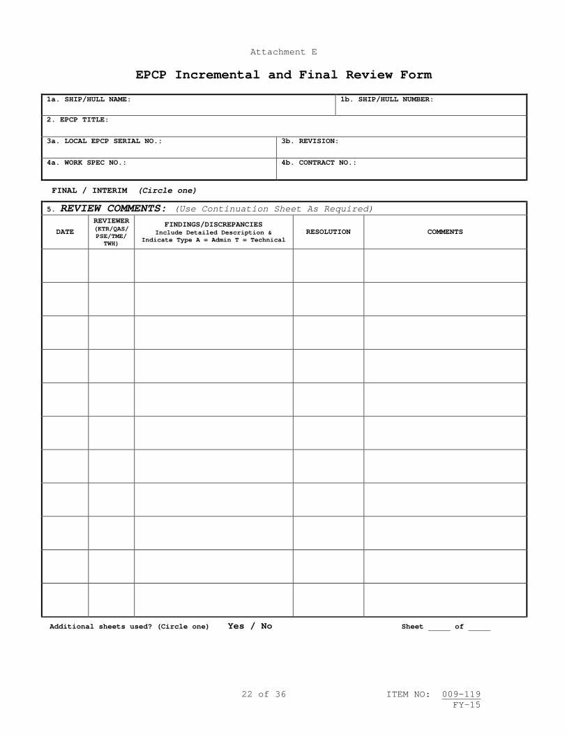
22 of 36 ITEM NO: 009-119 FY-15
Attachment E
EPCP Incremental and Final Review Form
1a. SHIP/HULL NAME:
1b. SHIP/HULL NUMBER:
2. EPCP TITLE:
3a. LOCAL EPCP SERIAL NO.:
3b. REVISION:
4a. WORK SPEC NO.:
4b. CONTRACT NO.:
FINAL / INTERIM (Circle one)
5. REVIEW COMMENTS: (Use Continuation Sheet As Required)
DATE REVIEWER (KTR/QAS/ PSE/TME/
TWH)
FINDINGS/DISCREPANCIES Include Detailed Description &
Indicate Type A = Admin T = Technical RESOLUTION COMMENTS
Additional sheets used? (Circle one) Yes / No Sheet of

23 of 36 ITEM NO: 009-119 FY-15
1a. SHIP/HULL NAME:
1b. SHIP/HULL NUMBER:
2. EPCP TITLE:
3a. LOCAL EPCP SERIAL NO.:
3b. REVISION:
4a. WORK SPEC NO.:
4b. PLANNER:
4c. COMPANY/COMMAND:
4d. SHOP/CODE:
Final / Interim Review Comments (Circle one)
5. REVIEW COMMENTS: (Continuation Sheet)
DATE REVIEWER (KTR/QAS/ PSE/TME/
TWH)
FINDINGS/DISCREPANCIES Include Detailed Description &
Indicate Type A = Admin T = Technical RESOLUTION COMMENTS
Sheet of _____

24 of 36 ITEM NO: 009-119 FY-15
Attachment E
EPCP Incremental and Final Review Form Instructions
BLOCK 1a - SHIP/HULL NAME Enter the ship and hull name. Copy from EPCP Approval Form (Attachment B). BLOCK 1b - SHIP/HULL NUMBER Enter the ship and hull number. Copy from EPCP Approval Form (Attachment B). BLOCK 2 - EPCP Title Copy from EPCP Approval Form (Attachment B). BLOCK 3a – LOCAL EPCP SERIAL NUMBER Enter the local NSA/RMC EPCP serial number. Copy from EPCP Approval Form (Attachment B). BLOCK 3b – REVISION Enter the alpha-character starting with “-“, “A”, “B”, etc. to annotate the EPCP revision. BLOCK 4a – WORK SPECIFICATION NUMBER Copy from EPCP Approval Form (Attachment B). BLOCK 4b – CONTRACT NUMBER Copy from EPCP Approval Form (Attachment B). FINAL / INTERIM
- Circle “INTERIM” when form is used to document EPCP review comments and resolution in support of incremental certification.
- Circle “FINAL” when form is used to document EPCP review comments and resolution in support of final EPCP certification.
BLOCK 5 – REVIEW COMMENTS
- Date - Enter the date of the review. - Reviewer: Annotate the reviewer’s job position (e.g. QAS, PSE, KTR, etc…). - Findings/Discrepancies: Provide a brief description of the findings discovered
and whether they are technical or administrative (see definitions for each category below).
- Resolution – Provide information on the action taken to resolve identified discrepancies.
- Comments – Provide pertinent amplifying information. Technical: Findings which, based on a review of the applicable EPCP documentation and available OQE, are determined to have an impact on the ability to verify critical measurements or data, or to verify required conditions (i.e., cleanliness) or to verify that work was conducted in accordance with the EPCP. Administrative: Findings which have no bearing on the technical compliance of the repair but are found to be not in accordance with guidance provided in applicable EPCP governing instructions. Findings of this nature include typographical/ editorial errors.

25 of 36 ITEM NO: 009-119 FY-15
Attachment F
List of Surface Ship Critical Systems
This list applies to the following Ship Classes: CG47, DDG51, FFG7, LCC19, LCS, LHA1, LHA6, LHD1, LHD8, LPD4, LPD17, LSD41, LSD49, MCM1 and PC1.
Critical Systems List
Note: The NAVSEA 05 Technical Warrant Holder (TWH) and Ship Design Manager (SDM) shall be notified prior to starting work and upon completion of work (to include completion of pier-side testing and completion of at-sea testing) for all Critical Systems listed below with the exception of SSDG lube oil systems and generator pedestal bearings.
All Ship Classes
• Main Reduction Gear (MRG) - Includes internal components (coupling, clutches and main thrust bearing). If these components are outside the MRG, they are excluded. OD box removal is excluded.
• MRG Lube Oil (L/O) System – Includes external L/O system that is a part of the MRG and the sump. The L/O purification system, storage tanks and filling system are excluded.
• Steering System
LSD41, LSD49 and LPD17 Ship Classes
• Main Propulsion Diesel Engine (MPDE) • MPDE L/O System • Ship Service Diesel Generator (SSDG) L/O System and Generator Pedestal Bearings
PC1 and MCM1 Ship Classes
• MPDE • MPDE L/O System • Magnetic Minesweeping Gas Turbine Generator (MMGTG) L/O System • SSDG L/O System and Generator Pedestal Bearings
LHA6 Class and LHD8 Class
• SSDG L/O System and Generator Pedestal Bearings
LPD4, LHA1, LHD1 and LCC19 Classes
• Main Boiler • High Pressure/Low Pressure (HP/LP) Turbines • HP/LP Turbine L/O System
LCS Class
• MPDE • MPDE L/O System

26 of 36 ITEM NO: 009-119 FY-15
• SSDG L/O System
FFG7 Class
• SSDG L/O System
General Exclusions:
• Computer software associated with critical systems • Flex hoses • Instrumentation (pressure gages, thermometers, thermocouples) • Valve repairs (by-pass regulating, thermostatic control, air start distributor,
exhaust, relief valves, L/O unloader valves and temperature regulating valves) • Attached/detached pump repairs (includes mechanical seals) • Fuel injectors • Attached/detached fuel oil pumps • Strainers • Cleaning/inspection/testing of coolers • Resilient mounts • MRG dehumidifiers • In-shop work on small items (e.g., fuel pumps, fuel injector pop tests) can be
excluded at the discretion of the NSA CHENG. • Exhaust leak repairs
Critical System Boundaries
CG47
• MRG – The mechanical boundary begins at the input drive flange and ends at the
output shaft. – Includes all components within the gear case. – Includes the SSS clutches, power turbine brakes, sight flow indicators
(SFI), input shaft seals, turning gear, attached L/O pump drive gears, attached CRP pump drive gears, foundation bolts, MRG sump.
– Excludes the CPP pumps, L/O pumps, dehumidifier, turning gear motor, SFI thermometers, and all electrical components beyond the first electrical connection (cannon plug) outside of the gear case.
• MRG L/O System – Includes the L/O unloader and the external L/O system that is a part of the
MRG. – Excludes L/O pump mechanical seals, attached L/O pump, L/O cooler, gages and
gage tubing from the gage back to the last mechanical connection before the MRG.
• Steering System – The mechanical boundary includes the rudder ram and tiller (including the
pins). – The hydraulic boundaries include the pump, power unit and all associated
hydraulic piping used to operate the rudder. – The controls boundary ends at but includes the actuator. – Includes the steering pumps, trickwheel box, and feedback linkages. – Excludes the oil distribution (OD) box, main pump motor, hydraulic oil
cooler, rudder stock and rudder seal, thermometers, pressure switches, transducers and gages.

27 of 36 ITEM NO: 009-119 FY-15
DDG51
• MRG – The mechanical boundary begins at the input drive flange and ends at the
output shaft. – Includes all components within the gear case. – Includes the SSS clutches, sight flow indicators (SFI), input shaft seals,
turning gear, attached L/O pump drive gears, foundation bolts, and MRG sump. – Excludes the power turbine brake, CPP pumps, dehumidifier, SFI thermometers,
and all electrical components beyond the first electrical connection (cannon plug) outside of the gear case.
• MRG L/O System – Includes the L/O temperature regulating valves (1-RLO-V-32, 2-RLO-V-32), L/O
cooler (oil side), and the external L/O system that is a part of the MRG. – Excludes the L/O pumps, attached L/O pump, L/O cooler (seawater side), gages
and gage tubing from the gage back to the last mechanical connection before the MRG.
• Steering System – The mechanical boundary includes the rudder ram and tiller (including the
pins). – The hydraulic boundaries include the pump, power unit and all associated
hydraulic piping used to operate the rudder. – The controls boundary ends at but includes the actuator. – Includes the steering pumps, trickwheel box, and feedback linkages. – Excludes the oil distribution (OD) box, main pump motor, hydraulic oil
cooler, rudder stock and rudder seal, thermometers, pressure switches, transducers and gages.
FFG7
• MRG – The mechanical boundary begins at the input drive flange and ends at the
output shaft. – Includes all components within the gear case. – Includes the SSS clutches, sight flow indicators (SFI), input shaft seals,
turning gear, shaft brake, attached CPP pump drive gears, foundation bolts, and MRG sump.
– Excludes the power turbine brake, attached CPP pump, electric CPP pump, dehumidifier, SFI thermometers, and all electrical components beyond the first electrical connection (cannon plug) outside of the gear case.
• MRG L/O System – Includes the L/O unloader (RLO-V8), L/O temperature regulating valve (RLO-
V4) and the external L/O system that is a part of the MRG. – Excludes the L/O pumps, L/O coast-down pump, L/O cooler, gages and gage
tubing from the gage back to the last mechanical connection before the MRG. • Steering System
– The mechanical boundary includes the rudder ram and tiller (including the pins).
– The hydraulic boundaries include the pump, rotary hydraulic power unit and all associated hydraulic piping used to operate the rudder.
– The controls boundary ends at but includes the actuator. – Includes the steering pumps, trickwheel box, and feedback linkages. – Excludes the oil distribution (OD) box, main pump motor, hydraulic oil
cooler, rudder stock and rudder seal, thermometers, pressure switches, transducers and gages.
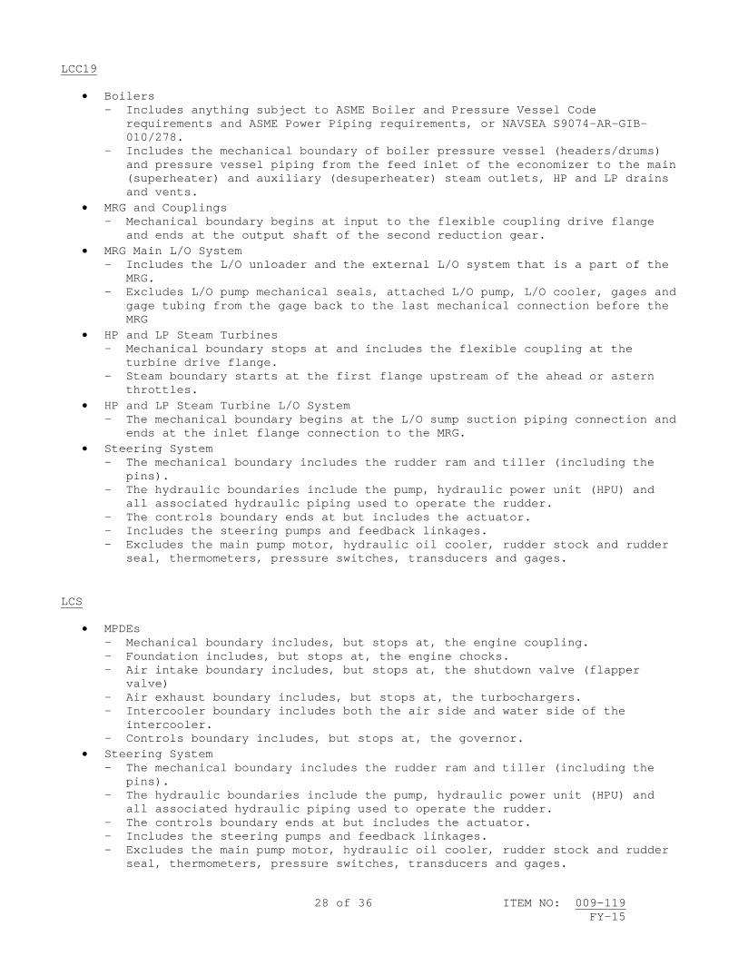
28 of 36 ITEM NO: 009-119 FY-15
LCC19
• Boilers – Includes anything subject to ASME Boiler and Pressure Vessel Code
requirements and ASME Power Piping requirements, or NAVSEA S9074-AR-GIB-010/278.
– Includes the mechanical boundary of boiler pressure vessel (headers/drums) and pressure vessel piping from the feed inlet of the economizer to the main (superheater) and auxiliary (desuperheater) steam outlets, HP and LP drains and vents.
• MRG and Couplings – Mechanical boundary begins at input to the flexible coupling drive flange
and ends at the output shaft of the second reduction gear. • MRG Main L/O System
– Includes the L/O unloader and the external L/O system that is a part of the MRG.
– Excludes L/O pump mechanical seals, attached L/O pump, L/O cooler, gages and gage tubing from the gage back to the last mechanical connection before the MRG
• HP and LP Steam Turbines – Mechanical boundary stops at and includes the flexible coupling at the
turbine drive flange. – Steam boundary starts at the first flange upstream of the ahead or astern
throttles. • HP and LP Steam Turbine L/O System
– The mechanical boundary begins at the L/O sump suction piping connection and ends at the inlet flange connection to the MRG.
• Steering System – The mechanical boundary includes the rudder ram and tiller (including the
pins). – The hydraulic boundaries include the pump, hydraulic power unit (HPU) and
all associated hydraulic piping used to operate the rudder. – The controls boundary ends at but includes the actuator. – Includes the steering pumps and feedback linkages. – Excludes the main pump motor, hydraulic oil cooler, rudder stock and rudder
seal, thermometers, pressure switches, transducers and gages.
LCS
• MPDEs – Mechanical boundary includes, but stops at, the engine coupling. – Foundation includes, but stops at, the engine chocks. – Air intake boundary includes, but stops at, the shutdown valve (flapper
valve) – Air exhaust boundary includes, but stops at, the turbochargers. – Intercooler boundary includes both the air side and water side of the
intercooler. – Controls boundary includes, but stops at, the governor.
• Steering System – The mechanical boundary includes the rudder ram and tiller (including the
pins). – The hydraulic boundaries include the pump, hydraulic power unit (HPU) and
all associated hydraulic piping used to operate the rudder. – The controls boundary ends at but includes the actuator. – Includes the steering pumps and feedback linkages. – Excludes the main pump motor, hydraulic oil cooler, rudder stock and rudder
seal, thermometers, pressure switches, transducers and gages.

29 of 36 ITEM NO: 009-119 FY-15
– Water-jet steering boundaries include the hydraulic system piping and hoses outboard to and including the hydraulic cylinders. Included is the feedback mechanism used to indicate cylinder position.
LHA1
• Boilers – Includes anything subject to ASME Boiler and Pressure Vessel Code
requirements and ASME Power Piping requirements, or NAVSEA S9074-AR-GIB-010/278.
– Includes the mechanical boundary of boiler pressure vessel (headers/drums) and pressure vessel piping from the feed inlet of the economizer to the main (superheater) and auxiliary (desuperheater) steam outlets, HP and LP drains and vents.
• MRG and Couplings – Mechanical boundary begins at input to the flexible coupling drive flange
and ends at the output shaft of the second reduction gear. • MRG Main L/O System
– Includes the L/O unloader and the external L/O system that is a part of the MRG.
– Excludes L/O pump mechanical seals, attached L/O pump, L/O cooler, gages and gage tubing from the gage back to the last mechanical connection before the MRG
• HP and LP Steam Turbines – Mechanical boundary stops at and includes the flexible coupling at the
turbine drive flange. – Steam boundary starts at the first flange upstream of the ahead or astern
throttles. • HP and LP Steam Turbine L/O System
– The mechanical boundary begins at the L/O sump suction piping connection and ends at the inlet flange connection to the MRG.
• Steering System – The mechanical boundary includes the rudder ram and tiller (including the
pins). – The hydraulic boundaries include the pump, hydraulic power unit (HPU) and
all associated hydraulic piping used to operate the rudder. – The controls boundary ends at but includes the actuator. – Includes the steering pumps and feedback linkages. – Excludes the main pump motor, hydraulic oil cooler, rudder stock and rudder
seal, thermometers, pressure switches, transducers and gages. LHD1
• Boilers – Includes anything subject to ASME Boiler and Pressure Vessel Code
requirements and ASME Power Piping requirements, or NAVSEA S9074-AR-GIB-010/278.
– Includes the mechanical boundary of boiler pressure vessel (headers/drums) and pressure vessel piping from the feed inlet of the economizer to the main (superheater) and auxiliary (desuperheater) steam outlets, HP and LP drains and vents.
• MRG and Couplings – Mechanical boundary begins at input to the flexible coupling drive flange
and ends at the output shaft of the second reduction gear. • MRG Main L/O System
– Includes the L/O unloader and the external L/O system that is a part of the MRG.
– Excludes L/O pump mechanical seals, attached L/O pump, L/O cooler, gages and

30 of 36 ITEM NO: 009-119 FY-15
gage tubing from the gage back to the last mechanical connection before the MRG
• HP and LP Steam Turbines – Mechanical boundary stops at and includes the flexible coupling at the
turbine drive flange. – Steam boundary starts at the first flange upstream of the ahead or astern
throttles. • HP and LP Steam Turbine L/O System
– The mechanical boundary begins at the L/O sump suction piping connection and ends at the inlet flange connection to the MRG.
• Steering System – The mechanical boundary includes the rudder ram and tiller (including the
pins). – The hydraulic boundaries include the pump, hydraulic power unit (HPU) and
all associated hydraulic piping used to operate the rudder. – The controls boundary ends at but includes the actuator. – Includes the steering pumps and feedback linkages. – Excludes the main pump motor, hydraulic oil cooler, rudder stock and rudder
seal, thermometers, pressure switches, transducers and gages. LPD4
• Boilers – Includes anything subject to ASME Boiler and Pressure Vessel Code
requirements and ASME Power Piping requirements, or NAVSEA S9074-AR-GIB-010/278.
– Includes the mechanical boundary of boiler pressure vessel (headers/drums) and pressure vessel piping from the feed inlet of the economizer to the main (superheater) and auxiliary (desuperheater) steam outlets, HP and LP drains and vents.
• MRG and Couplings – Mechanical boundary begins at input to the flexible coupling drive flange
and ends at the output shaft of the second reduction gear. • MRG Main L/O System
– Includes the L/O unloader and the external L/O system that is a part of the MRG.
– Excludes L/O pump mechanical seals, attached L/O pump, L/O cooler, gages and gage tubing from the gage back to the last mechanical connection before the MRG
• HP and LP Steam Turbines – Mechanical boundary stops at and includes the flexible coupling at the
turbine drive flange. – Steam boundary starts at the first flange upstream of the ahead or astern
throttles. • HP and LP Steam Turbine L/O System
– The mechanical boundary begins at the L/O sump suction piping connection and ends at the inlet flange connection to the MRG.
• Steering System – The mechanical boundary includes the rudder ram and tiller (including the
pins). – The hydraulic boundaries include the pump, hydraulic power unit (HPU) and
all associated hydraulic piping used to operate the rudder. – The controls boundary ends at but includes the actuator. – Includes the steering pumps and feedback linkages. – Excludes the main pump motor, hydraulic oil cooler, rudder stock and rudder
seal, thermometers, pressure switches, transducers and gages. LPD17

31 of 36 ITEM NO: 009-119 FY-15
• MPDE – Mechanical boundary includes but stops at the Gieslinger Coupling. – Foundation boundary includes but stops at the engine chocks. – Air intake boundary includes but stops at the shutdown valve (flapper valve) – Air exhaust boundary includes but stops at the turbochargers. – Intercooler boundary includes both the air side and water side of the
intercooler. – Controls boundary includes but stops at the machinery control interface
(commonly known as the "blue box"). • MPDE L/O System
– Includes external L/O system that is a part of the MPDE. The L/O purification system, storage tanks, filling system and L/O pumps are excluded.
• MRG and Couplings – Mechanical boundary begins at input to the flexible coupling drive flange
and ends at the output shaft of the second reduction gear. • MRG Main L/O System
– Includes the L/O unloader and the external L/O system that is a part of the MRG.
– Excludes the L/O pump mechanical seals, attached L/O pump, L/O cooler, gages and gage tubing from the gage back to the last mechanical connection before the MRG
• Steering System – The mechanical boundary includes the rudder ram and tiller (including the
pins). – The hydraulic boundaries include the pump, hydraulic power unit (HPU) and
all associated hydraulic piping used to operate the rudder. – The controls boundary ends at but includes the actuator. – Includes the steering pumps and feedback linkages. Excludes the oil
distribution (OD) box, main pump motor, rudder stock and rudder seal, hydraulic oil cooler, HPU mechanical seal, tiller linkage bearings, thermometers, pressure switches, transducers and gages.
LSD41
• MPDE – Mechanical boundary includes but stops at the Gieslinger Coupling. – Foundation boundary includes but stops at the engine chocks. – Air intake boundary includes but stops at the shutdown valve (flapper valve) – Air exhaust boundary includes but stops at the turbochargers. – Intercooler boundary includes both the air side and water side of the
intercooler. – Controls boundary includes but stops at the governor.
• MPDE L/O System – Includes external L/O system that is a part of the MPDE. The L/O
purification system, storage tanks and filling system are excluded. • MRG and Couplings
– Mechanical boundary begins at input to the flexible coupling drive flange and ends at the output shaft of the second reduction gear.
• MRG Main L/O System – Includes the L/O unloader and the external L/O system that is a part of the
MRG. – Excludes L/O pump mechanical seals, attached L/O pump, L/O cooler, gages and
gage tubing from the gage back to the last mechanical connection before the MRG
• Steering System – The mechanical boundary includes the rudder ram and tiller (including the
pins).

32 of 36 ITEM NO: 009-119 FY-15
– The hydraulic boundaries include the pump, hydraulic power unit (HPU) and all associated hydraulic piping used to operate the rudder.
– The controls boundary ends at but includes the actuator. – Includes the steering pumps and feedback linkages. Excludes the oil
distribution (OD) box, main pump motor, rudder stock and rudder seal, hydraulic oil cooler, thermometers, pressure switches, transducers and gages.
LSD49
• MPDE – Mechanical boundary includes but stops at the Gieslinger Coupling. – Foundation boundary includes but stops at the engine chocks. – Air intake boundary includes but stops at the shutdown valve (flapper valve) – Air exhaust boundary includes but stops at the turbochargers. – Intercooler boundary includes both the air side and water side of the
intercooler. – Controls boundary includes but stops at the governor.
• MPDE L/O System – Includes external L/O system that is a part of the MPDE. The L/O
purification system, storage tanks and filling system are excluded. • MRG and Couplings
– Mechanical boundary begins at input to the flexible coupling drive flange and ends at the output shaft of the second reduction gear.
• MRG Main L/O System – Includes the L/O unloader and the external L/O system that is a part of the
MRG. – Excludes L/O pump mechanical seals, attached L/O pump, L/O cooler, gages and
gage tubing from the gage back to the last mechanical connection before the MRG
• Steering System – The mechanical boundary includes the rudder ram and tiller (including the
pins). – The hydraulic boundaries include the pump, hydraulic power unit (HPU) and
all associated hydraulic piping used to operate the rudder. – The controls boundary ends at but includes the actuator. – Includes the steering pumps and feedback linkages. Excludes the oil
distribution (OD) box, the main pump motor, rudder stock and rudder seal, hydraulic oil cooler, thermometers, pressure switches, transducers and gages.
MCM1
• MPDE – Mechanical boundary includes, but stops at, the flywheel. – Foundation boundary includes and stops at the engine rail. – Air intake boundary includes but stops at the air filter. – Air exhaust boundary includes but stops at the turbochargers. – Controls boundary includes but stops at the governor actuator.
• MPDE L/O System – Includes external L/O system that is a part of the MPDE. The L/O
purification system, storage tanks and filling system are excluded. • Steering System
– The mechanical boundary includes the rudder ram and tiller (including the pins).
– The hydraulic boundaries include the pump, hydraulic power unit (HPU) and all associated hydraulic piping used to operate the rudder.
– The controls boundary ends at but includes the actuator.

33 of 36 ITEM NO: 009-119 FY-15
– Includes the steering pumps and feedback linkages. – Excludes the main pump motor, hydraulic oil cooler, rudder stock and rudder
seal, thermometers, pressure switches, transducers and gages. PC1
• MPDE – Mechanical boundary includes but stops at the flywheel. – Foundation boundary includes and stops at the engine rail. – Air intake boundary includes but stops at the air filter. – Air exhaust boundary includes but stops at the turbochargers. – Controls boundary includes but stops at the governor actuator. – Gearboxes are excluded.
• MPDE L/O System – Includes external L/O system that is a part of the MPDE. The L/O
purification system, storage tanks and filling system are excluded. • Steering System
– The mechanical boundary includes the rudder ram and tiller (including the pins).
– The hydraulic boundaries include the pump, hydraulic power unit (HPU) and all associated hydraulic piping used to operate the rudder.
– The controls boundary ends at but includes the actuator. – Includes the steering pumps and feedback linkages. – Excludes the main pump motor, hydraulic oil cooler, rudder stock and rudder
seal, thermometers, pressure switches, transducers and gages.
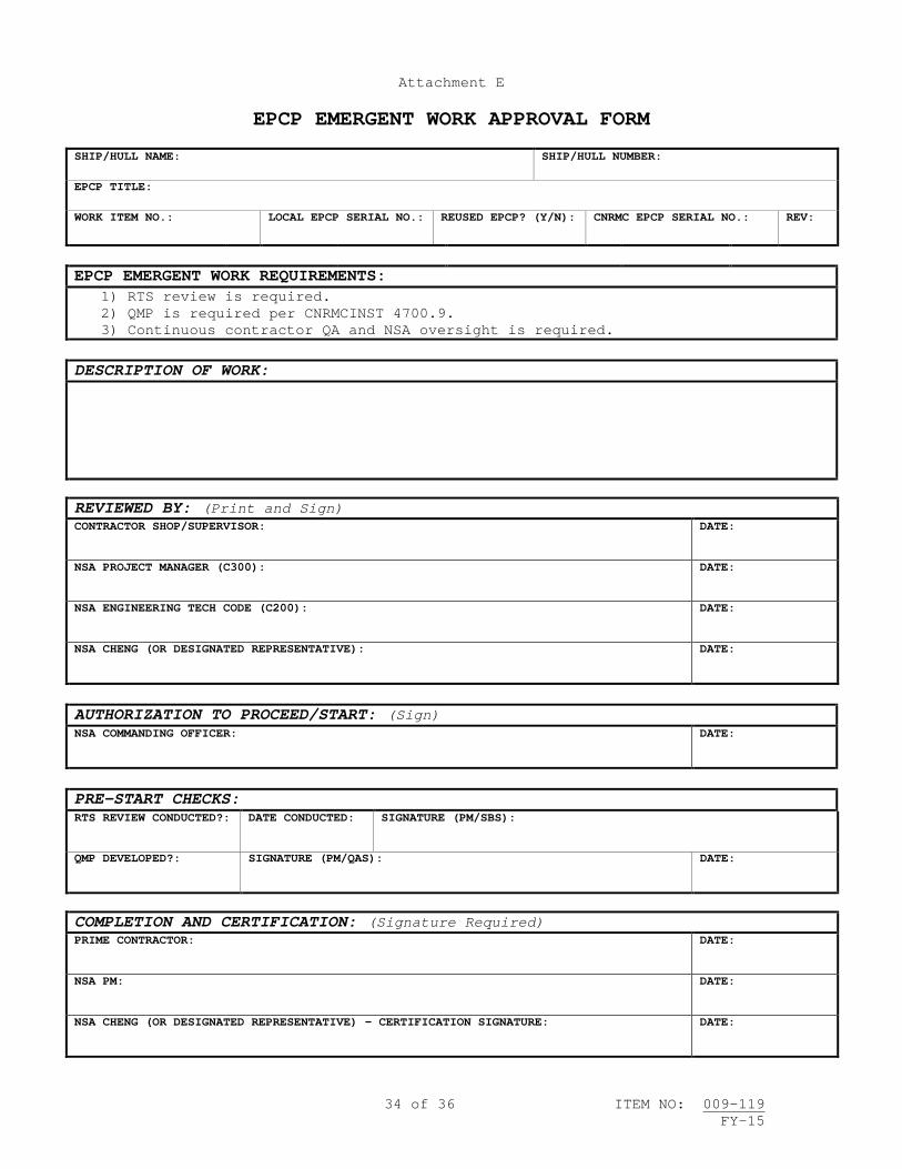
34 of 36 ITEM NO: 009-119 FY-15
Attachment E
EPCP EMERGENT WORK APPROVAL FORM SHIP/HULL NAME:
SHIP/HULL NUMBER:
EPCP TITLE: WORK ITEM NO.:
LOCAL EPCP SERIAL NO.:
REUSED EPCP? (Y/N):
CNRMC EPCP SERIAL NO.:
REV:
EPCP EMERGENT WORK REQUIREMENTS: 1) RTS review is required. 2) QMP is required per CNRMCINST 4700.9. 3) Continuous contractor QA and NSA oversight is required.
DESCRIPTION OF WORK:
REVIEWED BY: (Print and Sign) CONTRACTOR SHOP/SUPERVISOR:
DATE:
NSA PROJECT MANAGER (C300):
DATE:
NSA ENGINEERING TECH CODE (C200):
DATE:
NSA CHENG (OR DESIGNATED REPRESENTATIVE):
DATE:
AUTHORIZATION TO PROCEED/START: (Sign) NSA COMMANDING OFFICER:
DATE:
PRE-START CHECKS: RTS REVIEW CONDUCTED?:
DATE CONDUCTED:
SIGNATURE (PM/SBS):
QMP DEVELOPED?:
SIGNATURE (PM/QAS): DATE:
COMPLETION AND CERTIFICATION: (Signature Required) PRIME CONTRACTOR:
DATE:
NSA PM:
DATE:
NSA CHENG (OR DESIGNATED REPRESENTATIVE) – CERTIFICATION SIGNATURE:
DATE:

35 of 36 ITEM NO: 009-119 FY-15
Attachment E
EPCP EMERGENT WORK APPROVAL FORM SHIP/HULL NAME: Enter the ship's name. SHIP/HULL NUMBER: Enter the ship's hull number. EPCP TITLE: Enter a descriptive title for the EPCP. Include system or equipment being worked and nature of the work (e.g. “NO. 1 MRG LUBO Cooler Tube Bundle, Repair”). WORK ITEM NUMBER: Enter the Work Item Number under which the emergent work is required. LOCAL EPCP SERIAL NUMBER: Enter the local NSA EPCP serial number for the EPCP to be developed for this work. REUSED EPCP?: Enter “Y” if all or part of a previously approved EPCP will be used to accomplish any portion of this emergent work. Enter “N” if new. CNRMC EPCP SERIAL NUMBER: If the EPCP is a reuse EPCP, enter the CNRMC Serial Number of the reused EPCP. If the EPCP is a new EPCP, enter “NA”. CNRMC EPCP REV: If the EPCP is a reuse EPCP, enter the revision of the reused EPCP. If the EPCP is a new EPCP, enter “NA”. EPCP EMERGENT WORK REQUIREMENTS: The following statements shall be included on all emergent work approval forms:
• RTS is required. • QMP is required per CNRMCINST 4700.9. • Continuous contractor QA and NSA oversight is required.
Additional requirement statements may be added as appropriate. DESCRIPTION OF WORK: Provide a clear description of the work to be conducted. As appropriate, include pertinent precautions, prerequisites, initial conditions and personnel qualification requirements. REVIEWED BY: The following individuals (or designated representatives) shall legibly print their name (Last, First, MI), sign and date this form to document that the form was completed in accordance with this instruction and that the information contained on the form is valid. These required signatures shall not be made until after all of the above information has been recorded on the form. Additionally, these three review signature shall be completed prior to submitting the form to the NSA CO for an “authorization to proceed” signature.
• Contractor or shop supervisor

36 of 36 ITEM NO: 009-119 FY-15
• NSA Project Manager • NSA Engineering Tech Code
AUTHORIZATION TO PROCEED/START: The NSA Commanding Officer (CO) shall, via signature and date, provide authorization for work to proceed under the EPCP emergent work process. This signature shall be made after securing all three required signatures. PRE-START CHECKS: The RTS and QMP requirements of this instruction shall be complied with and documented prior to starting work.
• RTS BRIEF CONDUCTED?: Enter “Y” if RTS brief was conducted. Work shall not commence until an RTS brief is completed.
• DATE CONDUCTED: Enter the date of the RTS brief. • SIGNATURE (PM/SBS): The NSA PM or SBS shall sign to confirm that a RTS
brief was conducted. This signature shall be recorded prior to starting work.
• QMP DEVELOPED?: Enter “Y” if a QMP was developed for this emergent work or if the QMP data for this work was included in the availability QMP. Work shall not commence until a QMP is developed for this work.
• SIGNATURE (PM/QAS): The NSA PM or QAS shall sign to confirm that a QMP was developed for this emergent work or that the QMP data was included in the availability QMP. This signature shall be recorded prior to starting work.
• DATE: Enter the date that the PM or QAS signature was made. COMPLETION AND CERTIFICATION: PRIME CONTRACTOR: The Prime Contractor Representative shall sign to certify that all work was conducted in compliance with the EPCP and that all OQE records complete, accurate and are included. NSA PM: The NSA PM shall sign to concur that the contractor conducted all work in compliance with the EPCP, that all OQE records complete, accurate and are included and that the EPCP is ready for certification and close-out. NSA CHENG (or Designated Representative) – Certification Signature: The NSA CHENG or his/her designated representative shall sign to certify that work specified in the EPCP is complete, that work was executed and tested in accordance with correct technical requirements, and that any non-conformances associated with the EPCP have been adjudicated and properly documented.

1 of 15 ITEM NO: 009-120 FY-15
NAVSEA STANDARD ITEM
FY-15 ITEM NO: 009-120 | DATE: 06 JAN 2014 | CATEGORY: I | 1. SCOPE: 1.1 Title: Fact Finding and Critique of Unplanned Events; manage 2. REFERENCES: 2.1 None 3. REQUIREMENTS: 3.1 Accomplish the requirements of this item upon discovery of an unplanned event as directed by the SUPERVISOR. 3.1.1 Ensure immediate corrective actions are taken to mitigate the impact of the unplanned event, reduce or confine the area of concern, and place the work site in a safe and stable condition. 3.1.2 Secure work until approval to recommence is authorized by the SUPERVISOR. 3.1.3 Accomplish preliminary investigation to obtain immediate first-hand information at the job site concerning the unplanned event and ensure adequate immediate corrective action has been taken. 3.1.4 Determine the severity level of problems associated with the unplanned event using Attachment A (Severity Classification Guide). 3.1.4.1 Severity Level One (critical) or Severity Level 2 (major) problems require an investigation and normally a Critique Meeting. 3.1.4.2 Severity Level 3 (minor) problems require an investigation, however a Critique Meeting is not required. 3.1.5 Provide update to the SUPERVISOR on the status of the preliminary investigation and the assigned severity level within 4 hours of being directed by the SUPERVISOR to conduct a critique. 3.1.6 Obtain SUPERVISOR concurrence that the immediate corrective actions have been taken.

2 of 15 ITEM NO: 009-120 FY-15
3.1.6.1 Resume work concurrently with Fact Finding Investigation process only with SUPERVISOR authorization. 3.1.7 Assign a Fact Finding Investigator to accomplish the Fact Finding Process. 3.1.7.1 Accomplish Fact Finding Investigation with the objective of preparing a complete chronological statement of the facts relative to the occurrences leading up to and through the unplanned event, and of the immediate corrective actions taken. Include only facts such as what happened, when, where, who was present, who took action, and what could have happened if the outcome was different. 3.1.7.2 Obtain written independent statements from all witnesses to the unplanned event to establish the relevant facts. 3.1.7.3 Review all appropriate references, technical work documents, or other information pertinent to the problem and ensure that they are available for examination and discussion at the Critique Meeting. 3.1.7.4 Review similar unplanned events and corrective actions previously documented to identify repeat problems and the effectiveness of those previous corrective actions. 3.1.7.5 Complete the Fact Finding Investigation prior to the Critique Meeting without being influenced by pressure to resume work. 3.1.7.6 Document the initial Fact Finding Investigation of the unplanned event using Attachment B (Fact Finding Report and Preparation Requirements). 3.1.7.7 Obtain a unique Fact Finding Report Serial Number from the SUPERVISOR. This number shall be used as the serial number for the Fact Finding Report and all related documents. 3.1.8 Assign a Critique Chairperson and identify required Critique Meeting members (Contractor, Government, Ship’s Force). 3.1.8.1 A Critique Meeting is normally required; however, based on the results of the investigation, it may be deemed not warranted. For Critique Meeting to be not warranted, the problem(s) must be fully understood, cause(s) clearly known, and there must be concurrence from the SUPERVISOR to not hold a Critique Meeting. 3.1.8.2 Submit one legible copy, in hard copy or approved transferrable media, of the preliminary Fact Finding report, Attachment B, to the SUPERVISOR prior to the Critique Meeting, or a final Fact Finding report,

3 of 15 ITEM NO: 009-120 FY-15
if the Critique Meeting is deemed not warranted, within 20 working days of being directed by the SUPERVISOR to conduct a critique. 3.1.9 Coordinate the time and location of the Critique Meeting with the SUPERVISOR and meeting members. Ensure appropriate personnel (including ships force) are notified of the time, location and subject of the Critique Meeting. 3.1.10 Conduct Critique Meeting within 24 hours of being directed by the SUPERVISOR to conduct a critique. 3.1.10.1 Commencement of the Critique Meeting may be extended up to 3 working days with SUPERVISOR authorization. 3.1.11 Document all attendees using Attachment C, the Critique Meeting Attendance Sheet. 3.1.12 Ensure all pertinent documentation is available and distributed at the Critique Meeting (e.g. Fact Finding Report, appropriate references, technical work documents, chronological statement of relative facts, other information relevant to the problem and a list of any similar problems and corrective actions previously documented). 3.1.13 Introduce the Critique Chairperson, Fact Finding Investigator and all meeting members at the commencement of the Critique Meeting. 3.1.14 Brief all attendees that the purpose of the meeting is to encourage open discussion of the relevant facts and problems associated with an unplanned event, so that apparent causes of the problems and effective solutions can be determined. Critique Meetings are not examinations or investigations for the purpose of disciplinary action. Any disciplinary action investigation will be conducted separately and independently of this critique process. 3.1.15 Review all pertinent documentation and open the floor for discussion to determine any additional relevant facts. Obtain agreement/consensus on the relevant facts from all attending personnel. 3.1.16 Update the chronological statement of relevant facts to reflect additional pertinent information discovered during the Critique Meeting. 3.1.17 Document each problem identified during the Critique Meeting on the List of Problems and Corrective Actions form, Attachment D. 3.1.18 Coordinate with the SUPERVISOR to assign actions for each problem to the appropriate contractor or designated representative of an organization.
4 of 15 ITEM NO: 009-120 FY-15
3.1.18.1 More than one action may be required for each problem. 3.1.18.2 Ensure the contractor or designated representative of the organization assigned an action item signs the Fact Finding Report Form, Attachment B, acknowledging concurrence. 3.1.18.3 Ensure a Cause and Corrective Action (CCA) form, Attachment E, has been issued to the appropriate organization for follow-up and action. 3.1.19 Submit one legible copy, in hard copy or approved transferrable media, of the Critique paperwork and associated reports to the SUPERVISOR within three working days after conclusion of the Critique Meeting. 3.1.20 Ensure the organization assigned an action from the Critique Meeting provides an update using the Cause and Corrective Action Form, Attachment E, for all actions taken or in progress within two working days of assignment and as required thereafter. 3.1.20.1 All corrective actions must have an actual or estimated completion date. The terms “continuing” or “continuous” are not acceptable. If an action is of a repetitive or continuous nature, the completion date will match the date the policy for that action was disseminated. 3.1.21 Notify the SUPERVISOR of any new problems related to the unplanned event that are discovered while working action items. 3.1.21.1 Changes to the Fact Finding Report after the Critique Meeting was adjourned will only be made by the Chairperson with SUPERVISOR concurrence. 3.1.22 Manage the Fact Finding and Critique Process for each problem until satisfactory conclusion. 3.1.23 Collect all completed Cause and Corrective Action forms to review for completion and compliance. 3.1.24 Submit one legible copy, in hard copy or approved transferable media, of the Final Fact Finding report listing the results of the investigation, along with all associated paperwork to the SUPERVISOR within 20 working days of being directed to conduct a critique. 3.1.25 Maintain a record of all Fact Finding and Critique process documents for a minimum of three years.

5 of 15 ITEM NO: 009-120 FY-15
3.1.25.1 Stored records shall be used to conduct trend analysis for any similar problems and corrective actions previously documented to identify repeat problems and to evaluate the effectiveness of those corrective actions. 4. NOTES: 4.1 Definitions. 4.1.1 Apparent Cause: The most likely reason for a problem to have occurred based on a review of relevant facts determined during the preliminary investigation, subsequent investigations and the critique. There may be more than one apparent cause for a problem. 4.1.2 Critique: A formal review meeting of a critical or major unplanned event (as defined in Attachment A, Severity Level Classification Guide) to determine the relevant facts, to provide an accurate and documented chronology of the relevant occurrences surrounding the event (before, during and after), to determine the apparent causes of problems and their severity levels, and to validate the adequacy of the immediate corrective actions taken. Apparent cause(s) and corrective and preventive action(s) for each problem should be determined during the critique. Participants will include personnel directly involved with or knowledgeable about the incident, system, or work processes and a cross-section of senior level management. 4.1.3 Fact Finding: A formal investigation conducted by the contractor for all unplanned events to identify and document the facts surrounding the unplanned event to include the identification of all problems and their severity levels, apparent causes, immediate corrective actions, and short and long-term corrective actions taken to prevent recurrence of the unplanned event. A formal Critique Meeting may be conducted as part of some Fact Findings. The results of the Fact Finding and Critique Meeting (when conducted) are documented in a Fact Finding report. 4.1.4 Critique Chairperson: Appointed by the contractor and responsible for ensuring that the problems associated with unplanned events are properly identified, characterized by severity level, investigated, critiqued (if necessary), have adequate short and long-term corrective actions identified, and are reported in a timely manner. Collects the Cause and Corrective Action (CCA) memos for each problem identified in the critique meeting, reviews them for adequacy, prepares the final Fact Finding report and obtains the concurrence of the SUPERVISOR with the final Fact Finding report. 4.1.5 Fact Finding Investigator: Appointed by the contractor to conduct Investigation of an unplanned event to determine the relevant facts, chronology, and circumstances of the event and to determine if the event

6 of 15 ITEM NO: 009-120 FY-15
warrants conducting a critique meeting. Provides results of the investigation to the Critique Chairperson. 4.1.6 Fact Finding Report Serial Number: Each unplanned event to be investigated is assigned a unique serial number used for accountability and tracking. Serial Numbers will be provided by the SUPERVISOR. 4.1.7 Immediate Corrective Action: Action(s) taken immediately upon discovery of an unplanned event to put the component or system in a safe condition and correct any problems requiring immediate attention so that it does not escalate into a greater problem. 4.1.8 Long-Term Corrective Action: Action(s) taken to correct the apparent cause(s) of the problem(s) to minimize the probability of recurrence and to correct any problems that may be discovered during the fact finding and critique process. 4.1.9 Short-Term Corrective Action: Temporary action(s) taken to correct or mitigate the apparent cause(s) of the problem(s) associated with an unplanned event. Such actions minimize the probability of problem recurrence and allow work to continue until long-term corrective actions are taken. 4.1.10 Unplanned Event: An unexpected occurrence that is not normal behavior or anticipated condition for the process. 4.2 Problems identified to Ship’s Force will only require a response for immediate and short-term corrective action. Long-term corrective actions will be taken through the established processes within the command. Systemic problem areas identified may be addressed through other administrative reporting procedures with cognizant Immediate Superior In Command (ISIC) personnel. 4.3 If problems are identified to contractors working for AIT managers, the Alteration Installation Team (AIT) managers are required to initiate and conduct the Fact Finding process for unplanned events. The Naval Supervisory Authority (NSA) shall participate as necessary to ensure effectiveness. 4.4 A Process Flow Chart, Appendix F is provided as a quick reference guide for the Critique process.

7 of 15 ITEM NO: 009-120 FY-15
ATTACHMENT A
SEVERITY LEVEL CLASSIFICATION GUIDE 1. PROBLEM SEVERITY LEVELS: 1.1 Problems associated with unplanned events shall be assigned one of three levels of severity (Level One, 2, or 3) to distinguish those problems that have the most impact on an activity in accomplishing its mission. Severity levels also help ensure appropriate resources are focused on the most significant problems. 1.2 For each unplanned event identified, attempt to determine the level of severity of the problem(s) during the preliminary investigation. 1.2.1 Problems meeting the criteria of Levels One or 2 normally require both a Fact Finding Investigation and a Critique Meeting to determine and correct the cause(s) of the unplanned event. 1.2.2 Problems meeting the criteria of Level 3 shall be investigated to determine and correct the cause(s) of the unplanned event, normally on the spot, but a Fact Finding Report is not required for a Level 3 problem. For completeness, Level 3 problems identified in conjunction with a Fact Finding Investigation for a Level One or 2 problem shall be included in the Fact Finding Report for the Level One or 2 problem. 1.3 The severity level for each problem shall be determined using the following guidelines: 1.3.1 Level One “CRITICAL” 1.3.1.1 A problem or trend which has or could endanger personnel, result in significant rework, significant environmental hazard, significant personnel injury or renders safeguards ineffective. Level One problems normally require Technical Authority and/or senior management attention to resolve. 1.3.1.2 Level One deficiencies often result in significant recovery time/cost. A series or trend of Level 2 deficiencies should be grouped together and identified as Level One. Examples of Level One problems include: -Equipment damage greater than $50K -Any rework costing over $100K -Work Control/Tag Out violations -Loss of control during testing -Crane accident resulting in an event such as derailment, overload, injury to personnel, dropped material, equipment damage, unplanned contact between the load, crane or object -Serious personnel injury (i.e. chemical burn, electric shock, fall)

8 of 15 ITEM NO: 009-120 FY-15
-Flammable liquid spill -Fire or Flooding -Broken weight handling equipment (while in use) -Personnel in a toxic environment without proper gas free certification (space not gas free) 1.3.2 Level 2 “MAJOR” 1.3.2.1 A problem or trend which, if not found and corrected, has the potential to result in a Level One problem or which results in equipment degradation requiring DFS approval. Level 2 problems may require Technical Authority involvement and senior management attention. 1.3.2.2 A series or trend of Level 3 deficiencies should be grouped together and identified as Level 2. Examples of Level 2 problems include: -Equipment damage of less than $50K -Using improper test procedures -Loss of cleanliness of a system or equipment -Component found out of position (i.e. valve or switch open in lieu of shut) -Systemic problems regarding safety requirements -Personnel in a toxic environment without gas free certification properly posted (not posted but space was Gas Free) -Not following written procedures (e.g. Expanded Process Control Procedures, Process Control Procedures, Test Plan) 1.3.3 Level 3 “MINOR” 1.3.3.1 Isolated deficiencies with minimal overall impact and no significant consequences. Level 3 problems are normally corrected on the spot (i.e. document the deficiency and brief personnel involved) with an immediate corrective action. Examples of Level 3 problems include: -Any problem not categorized as Level One or Level 2 -Required notification of the problem was not made in a timely manner -Paint sample taken at incorrect location -Required procedures not on site -OQE or reports not recorded or submitted in required time -Unsafe work practices -Poor craftsmanship -Repeated housekeeping violations
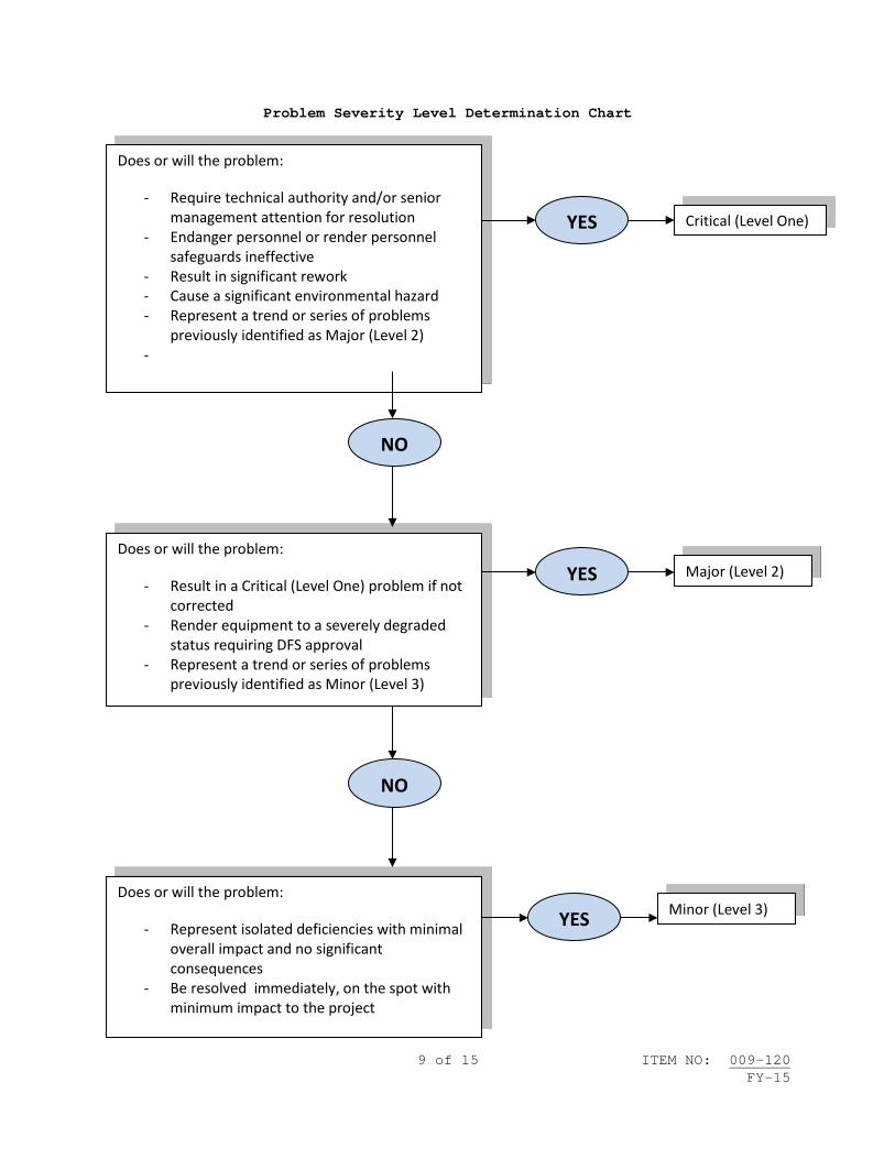
9 of 15 ITEM NO: 009-120 FY-15
Problem Severity Level Determination Chart
Does or will the problem:
- Require technical authority and/or senior management attention for resolution
- Endanger personnel or render personnel safeguards ineffective
- Result in significant rework - Cause a significant environmental hazard - Represent a trend or series of problems
previously identified as Major (Level 2) -
YES Critical (Level One)
NO
YES
NO
YES
Does or will the problem:
- Result in a Critical (Level One) problem if not corrected
- Render equipment to a severely degraded status requiring DFS approval
- Represent a trend or series of problems previously identified as Minor (Level 3)
Does or will the problem:
- Represent isolated deficiencies with minimal overall impact and no significant consequences
- Be resolved immediately, on the spot with minimum impact to the project
Major (Level 2)
Minor (Level 3)

10 of 15 ITEM NO: 009-120 FY-15
Attachment B FACT FINDING REPORT AND PREPARATION REQUIREMENTS
*Note: Mark the security classification on the report as applicable based on the sensitivity of the information contained in the report. 1. Preliminary Fact Finding Report: 1.1 An in-progress report that may consist of the following: 1.1.1 Fact Finding Report Form filled out with the “Preliminary Report” box checked. 1.1.2 List of Problems and Corrective Actions Form(s) (Attachment D). 1.1.3 Cause and Corrective Action Form(s) (Attachment E). 1.1.4 Chronological statement of relevant facts. 1.1.5 Any other document(s) used during the Fact Finding Investigation. 2. Final Fact Finding Report: 2.1 A final Fact Finding Report shall consist of the following: 2.1.1 Completed Fact Finding Report Form with the “Final Report” box checked and senior manager review. 2.1.2 Completed List of Problem and corrective Action Form(s) (Attachment D). 2.1.3 Completed Cause and corrective Action Form(s) (Attachment E) 2.1.4 Complete chronological statement of relevant facts from the unplanned event. 2.1.5 Any other document(s) used during the Fact Finding Investigation (e.g. Independent statements from individual(s), appropriate references, technical work documents). 2.1.6 Critique Meeting attendance form (Attachment C), if a Critique Meeting was held.
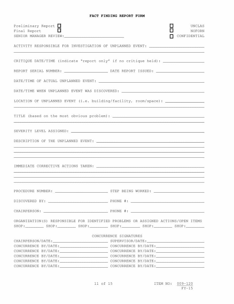
11 of 15 ITEM NO: 009-120 FY-15
FACT FINDING REPORT FORM
Preliminary Report UNCLAS Final Report NOFORN SENIOR MANAGER REVIEW:__________________________ CONFIDENTIAL ACTIVITY RESPONSIBLE FOR INVESTIGATION OF UNPLANNED EVENT: ________________________ ___________________________________________________________________________________ CRITIQUE DATE/TIME (indicate “report only” if no critique held): __________________ REPORT SERIAL NUMBER: ___________________ DATE REPORT ISSUED: _____________________ DATE/TIME OF ACTUAL UNPLANNED EVENT: ______________________________________________ DATE/TIME WHEN UNPLANNED EVENT WAS DISCOVERED: ____________________________________ LOCATION OF UNPLANNED EVENT (i.e. building/facility, room/space): _________________ ___________________________________________________________________________________ TITLE (based on the most obvious problem): ________________________________________ ___________________________________________________________________________________ SEVERITY LEVEL ASSIGNED: __________________________________________________________ DESCRIPTION OF THE UNPLANNED EVENT: _______________________________________________ ___________________________________________________________________________________ ___________________________________________________________________________________ ___________________________________________________________________________________ IMMEDIATE CORRECTIVE ACTIONS TAKEN: _______________________________________________ ___________________________________________________________________________________ ___________________________________________________________________________________ ___________________________________________________________________________________ PROCEDURE NUMBER: _______________________ STEP BEING WORKED: ______________________ DISCOVERED BY: __________________________ PHONE #: ________________________________ CHAIRPERSON: ____________________________ PHONE #: ________________________________ ORGANIZATION(S) RESPONSIBLE FOR IDENTIFIED PROBLEMS OR ASSIGNED ACTIONS/OPEN ITEMS SHOP:________ SHOP:________ SHOP:________ SHOP:________ SHOP:________ SHOP:________
CONCURRENCE SIGNATURES CHAIRPERSON/DATE:________________________ SUPERVISOR/DATE:_________________________ CONCURRENCE BY/DATE:_____________________ CONCURRENCE BY/DATE:_____________________ CONCURRENCE BY/DATE:_____________________ CONCURRENCE BY/DATE:_____________________ CONCURRENCE BY/DATE:_____________________ CONCURRENCE BY/DATE:_____________________ CONCURRENCE BY/DATE:_____________________ CONCURRENCE BY/DATE:_____________________ CONCURRENCE BY/DATE:_____________________ CONCURRENCE BY/DATE:_____________________

12 of 15 ITEM NO: 009-120 FY-15
ATTACHMENT C
CRITIQUE MEETING ATTENDANCE SHEET FORM REPORT SERIAL NUMBER: _____________ DATE/TIME: ____________________________ PRINT NAME ORGANIZATION/SHOP PHONE #
Check block if you are a Senior Manager ____________________________ ________________________________ ___________
____________________________ ________________________________ ___________
____________________________ ________________________________ ___________
____________________________ ________________________________ ___________
____________________________ ________________________________ ___________
____________________________ ________________________________ ___________
____________________________ ________________________________ ___________
____________________________ ________________________________ ___________
____________________________ ________________________________ ___________
____________________________ ________________________________ ___________
____________________________ ________________________________ ___________
____________________________ ________________________________ ___________
____________________________ ________________________________ ___________
____________________________ ________________________________ ___________
____________________________ ________________________________ ___________
____________________________ ________________________________ ___________
____________________________ ________________________________ ___________
____________________________ ________________________________ ___________
____________________________ ________________________________ ___________
____________________________ ________________________________ ___________
____________________________ ________________________________ ___________
____________________________ ________________________________ ___________
____________________________ ________________________________ ___________
____________________________ ________________________________ ___________
____________________________ ________________________________ ___________
____________________________ ________________________________ ___________

13 of 15 ITEM NO: 009-120 FY-15
ATTACHMENT D
LIST OF PROBLEMS AND CORRECTIVE ACTIONS REPORT SERIAL NUMBER: _____________ PROBLEM #: ___________________________ SEVERITY LEVEL: ___________________________ ORGANIZATION RESPONSIBLE FOR ANALYSIS AND RESOLUTION: ____________________________ PROBLEM STATEMENT: _______________________________________________________________ __________________________________________________________________________________ APPARENT CAUSES: _________________________________________________________________ __________________________________________________________________________________ __________________________________________________________________________________ SHORT-TERM CORRECTIVE ACTIONS: ___________________________________________________ __________________________________________________________________________________ __________________________________________________________________________________ __________________________________________________________________________________ __________________________________________________________________________________ ESTIMATED COMPLETION DATE: ___________ ACTUAL COMPLETION DATE: ___________________ PROBLEM #: ___________________________ SEVERITY LEVEL: ___________________________ ORGANIZATION RESPONSIBLE FOR ANALYSIS AND RESOLUTION: ____________________________ PROBLEM STATEMENT: _______________________________________________________________ __________________________________________________________________________________ APPARENT CAUSES: _________________________________________________________________ __________________________________________________________________________________ __________________________________________________________________________________ SHORT-TERM CORRECTIVE ACTIONS: ___________________________________________________ __________________________________________________________________________________ __________________________________________________________________________________ __________________________________________________________________________________ __________________________________________________________________________________ ESTIMATED COMPLETION DATE: ___________ ACTUAL COMPLETION DATE: ___________________ PROBLEM #: ___________________________ SEVERITY LEVEL: ___________________________ ORGANIZATION RESPONSIBLE FOR ANALYSIS AND RESOLUTION: ____________________________ PROBLEM STATEMENT: _______________________________________________________________ __________________________________________________________________________________ APPARENT CAUSES: _________________________________________________________________ __________________________________________________________________________________ __________________________________________________________________________________ SHORT-TERM CORRECTIVE ACTIONS: ___________________________________________________ __________________________________________________________________________________ __________________________________________________________________________________ __________________________________________________________________________________ __________________________________________________________________________________ ESTIMATED COMPLETION DATE: ___________ ACTUAL COMPLETION DATE: ___________________

14 of 15 ITEM NO: 009-120 FY-15
ATTACHMENT E
CAUSE AND CORRECTIVE ACTION FORM
REPORT SERIAL NUMBER: _____________________ SEVERITY LEVEL: ________________________ MANAGER/TECHNICAL CODE: ___________________ DATE ISSUED: __________________________ 1. This form contains the problem descriptions that were identified as being partially or wholly the responsibility of shop ______. As the __________________ manager, you are responsible to follow up and take the appropriate actions to correct the listed problems. PROBLEM # ___ DESCRIPTION: ________________________________________________________ ___________________________________________________________________________________ ___________________________________________________________________________________ ___________________________________________________________________________________ CAUSE: ____________________________________________________________________________ ___________________________________________________________________________________ ___________________________________________________________________________________ ___________________________________________________________________________________ SHORT-TERM CORRECTIVE ACTIONS: ____________________________________________________ ___________________________________________________________________________________ ___________________________________________________________________________________ ___________________________________________________________________________________ ESTIMATED COMPLETION DATE: _______________ ACTUAL COMPLETION DATE: ________________ LONG-TERM CORRECTIVE ACTIONS: _____________________________________________________ ___________________________________________________________________________________ ___________________________________________________________________________________ ___________________________________________________________________________________ ESTIMATED COMPLETION DATE: _______________ ACTUAL COMPLETION DATE: ________________ PROBLEM # ___ DESCRIPTION: ________________________________________________________ ___________________________________________________________________________________ ___________________________________________________________________________________ ___________________________________________________________________________________ CAUSE: ____________________________________________________________________________ ___________________________________________________________________________________ ___________________________________________________________________________________ ___________________________________________________________________________________ SHORT-TERM CORRECTIVE ACTIONS: ____________________________________________________ ___________________________________________________________________________________ ___________________________________________________________________________________ ___________________________________________________________________________________ ESTIMATED COMPLETION DATE: _______________ ACTUAL COMPLETION DATE: ________________ LONG-TERM CORRECTIVE ACTIONS: _____________________________________________________ ___________________________________________________________________________________ ___________________________________________________________________________________ ___________________________________________________________________________________ ESTIMATED COMPLETION DATE: _______________ ACTUAL COMPLETION DATE: ________________

15 of 15 ITEM NO: 009-120 FY-15
Attachment F
Process Flow Chart
Discovery of Unplanned Event
-Take immediate corrective action to stabilize the problem -Obtain firsthand information on site to ensure adequate immediate corrective action has been taken
Determine the Problem Severity Level using Attachment A and make appropriate notification of the need for an investigation and Critique Meeting to the SUPERVISOR
Schedule and conduct the Critique Meeting, normally within 24 hours of being directed by the SUPERVISOR to conduct a critique, but not longer than three
working days
When directed by the SUPERVISOR, commence the Fact Finding process associated with problem investigation, problem identification and reporting of unplanned events
Complete follow-on actions
Prepare Final Fact Finding Report per Attachment B
Maintain all Fact Finding and Critique Process records for the duration of the project in support of trend analysis. Ideally, records will be kept on hand for review during future similar unplanned events but records must be maintained for at least 3 years.
Obtain concurrence from Supervisor that corrective actions are adequate
Submit Final Fact Finding Report to the SUPERVISOR using attachment B and associated forms as applicable within 20 working days of being directed by the SUPERVISOR to critique.


1 of 2 ITEM NO: 009-121 FY-15
NAVSEA STANDARD ITEM
FY-15 ITEM NO: 009-121 ___ | DATE: 06 JAN 2014 | CATEGORY: I_____ | 1. SCOPE: 1.1 Title: Ship Assessment/Inspection Requirements; provide 2. REFERENCES: 2.1 None. 3. REQUIREMENTS: 3.1 Provide the services of qualified on-site technical representatives and resources to accomplish Ship Assessments/Inspections. 3.1.1 Provide Assessors that meet all qualification requirements for each specific Assessment/Inspection area assigned and the following general qualification requirements. 3.1.1.1 Have technical knowledge of the specified equipment or process, and have a documented history of conducting Material Assessments/Inspections on similar equipment or processes. 3.1.1.2 Have demonstrated competence with required Standard Work Templates (SWT) and procedures specified in the Class Maintenance Plan (CMP) and the Planned Maintenance system (PMS) database. 3.1.1.3 Have demonstrated competence with submitting technically accurate documentation of both satisfactory and unsatisfactory Assessment/Inspection results (OPNAV 4790 2-Kilo’s and Automated Work Requests). 3.1.2 Comply with the following requirements when conducting Assessments/Inspections and reporting deficient material conditions of assigned ships equipment/systems. 3.1.2.1 Integrate work requirements, setting of priorities, coordinating with the ship, and de-conflicting of other ship Assessments/Inspections as agreeable by the Government Project Team/Assessment Director. 3.1.2.2 Conduct Assessments/Inspections only using tasks from the Class Maintenance Plan (CMP) or Assessment Procedures (AP) Maintenance Requirement Cards (MRC) in the Planned Maintenance System (PMS) database.

2 of 2 ITEM NO: 009-121 FY-15
3.1.2.3 Verify all established procedures (e.g., CMP, MRC) are reviewed for technical accuracy and ability to comply with the procedure as written. 3.1.2.4 Inform Government Project Team/Assessment Director of any deficiencies or technical inaccuracies in the Assessment/Inspection procedures. 3.1.2.5 Submit Technical Feedback Report (TFBR) to the Government Project Team/Assessment Director to address any deficiencies or technical inaccuracies in the Assessment/Inspection procedure. Ensure TFBR describes what is required to properly perform Assessment/Inspection. 3.1.3 Document all Assessment/Inspection findings, whether satisfactory or unsatisfactory using an OPNAV 4790 2-Kilo or Automated Work Request (AWR). 3.1.3.1 The SUPERVISOR is the ultimate approval authority for review of 2-Kilo’s and AWR’s written during an Assessment/Inspection. Any corrections found necessary due to error or omission by the contractor shall be promptly corrected by the contractor. 4. NOTES: 4.1 None.