navigation intrumentation – vor · navigation instrument ... the hsi illustrated above is a type...
TRANSCRIPT
Navigation instrument - VOR Version 1.1 20 July 2016 Page 1
© IVAO HQ training department Training Documentation Manager Erwan L’hotellier
This manual is dedicated only for IVAOTM Network activities. This document must not be used in real aviation or in other networks
NAVIGATION INTRUMENTATION – VOR
1. Introduction
The VHF omnidirectional radio range (VOR) is an omnidirectional (360° of azimuth) range station which
operates in the very high frequency (VHF) band of the radio spectrum between 108 to 118MHz, sharing the
band from 108 to 112MHz with the localizer component of instrument landing systems (ILS).
The VOR is the basic short-range aid used to provide navigation guidance along airways, air traffic services
(ATS) routes, intermediate and final approach tracks, and specified tracks.
2. Bearing information
The VHF radio signal includes the station's Morse code identifier and electromagnetic signals that allows
the airborne receiving equipment to calculate the magnetic bearing from the station to the aircraft.
This magnetic bearing from the station to the aircraft is called the "radial".
A radial starts at the beacon and continues until the reception is granted.
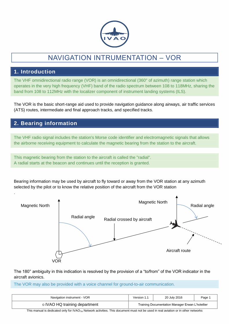
Bearing information may be used by aircraft to fly toward or away from the VOR station at any azimuth
selected by the pilot or to know the relative position of the aircraft from the VOR station
.
The 180° ambiguity in this indication is resolved by the provision of a “to/from” of the VOR indicator in the
aircraft avionics.
The VOR may also be provided with a voice channel for ground-to-air communication.
Magnetic North
VOR
Radial angle Radial crossed by aircraft
Radial angle Magnetic North
Aircraft route

Navigation instrument - VOR Version 1.1 20 July 2016 Page 2
© IVAO HQ training department Training Documentation Manager Erwan L’hotellier
This manual is dedicated only for IVAOTM Network activities. This document must not be used in real aviation or in other networks
3. Ground equipment: VOR
VOR are exploited over the Very High Frequency (VHF) band from 108 to 117.95 MHz with channels
spaced of 50 or 100 kHz (50 kHz for dense zones, 100 kHz elsewhere).
The first 4 MHz frequency range, from 108.0 to 111.95 MHz, is shared with the ILS band.
Two types of VOR beacons are used:
Terminal VOR (T-VOR): they are used in the terminal area of airports and cover a relatively small
geographic area protected from interference by other stations on the same frequency. T-VOR
output power is 50 W which allows covering a region from 1000 ft AGL up to and including
12000 ft AGL at radial distances out to 25 NM. The allocated band ranges from 108 to 111.850 MHz
with the 100 kHz digit being always even (example: 108.25MHz, 109 MHz)
En route VOR: they are used as route fixes within high or low airspace. Their output power is
200 W which provides a range up to 200 NM. The allocated band ranges from 112 to 117.950 MHz
Since it is normally used within approximately 130 NM of the station, the VOR is considered a short-range
navigation aid.
Distance measuring equipment (DME) is a useful adjunct to, and is normally collocated with a VOR. In such case the VOR is referred to as a VOR/DME.
Sometimes a TACAN is collocated with a VOR; the VOR is referred to as VORTAC. TACAN is tactical air navigation and it is a military equipment that provides both azimuth and distance components by equipment operating in the UHF band. The distance measuring equipment of TACAN is compatible with other DME equipment.
3.1. VOR performance limitations
VOR are used at times beyond 130 NM; however, the accuracy of navigation guidance derived from it
decreases with the increased range.
VOR is subject to line-of-sight limitations. This means that its signals can only be received at increasingly
higher altitudes as the distance of the aircraft from the station increases. The usable range of a VOR is also
proportional to its power (the greater the power output, the greater the effective range is).
The equation of line-of-sight distance (without obstacles):
𝐷(𝑁𝑀) = 1.23 × √𝐻𝑒𝑖𝑔ℎ𝑡 (𝑓𝑡)
Example: for 3000ft, D= 65NM; for 9000ft, D=115NM.

Navigation instrument - VOR Version 1.1 20 July 2016 Page 3
© IVAO HQ training department Training Documentation Manager Erwan L’hotellier
This manual is dedicated only for IVAOTM Network activities. This document must not be used in real aviation or in other networks
When overflying the VOR, aircraft will enter a “cone” of signal “softness” but its horizontal dimension at any
level is relatively small and has normally no noticeable effect on navigation.
Nevertheless, the VOR receiver becomes incapable of radial detection inside this cone. The VOR receiver
will display the OFF flag and the radial indicator should be at maximum deviation.
𝐷(𝑁𝑀) = 𝐻𝑒𝑖𝑔ℎ𝑡 (𝑓𝑡)
2× 1000
Example:
at 20000ft, D = 20/2 = 10 NM
at 4000ft D = 4/2 = 2NM
3.2. VOR accuracy and interference
The radial line is read in degrees of azimuth from the magnetic North and is technically accurate to within
±2°. The over-all system accuracy is ±5°.
The VORs are also subject to co-channel or adjacent frequency interference problems with other VOR or ILS.
3.3. Principles of VOR signals
The VOR beacon simultaneously transmits two signals:
A constant omnidirectional signal (30Hz) called the reference phase
A directional signal (30Hz) which rotates through 360°, during a 0.03 second system cycle (30Hz),
and consistently varies in phase through each rotation.
The two signals are only exactly in phase once during each rotation – when the directional signal is aligned
to the magnetic north.
The receiver onboard the aircraft will measure the phase between both signals which is independent of the
aircraft heading
Height
D

Navigation instrument - VOR Version 1.1 20 July 2016 Page 4
© IVAO HQ training department Training Documentation Manager Erwan L’hotellier
This manual is dedicated only for IVAOTM Network activities. This document must not be used in real aviation or in other networks
4. VOR on charts
The representation of the VOR on charts can take one of these symbols.
4.1. VOR only symbol
These are some examples of the VOR symbol on charts.
The representation using a circle is the Jeppesen representation.
The representation using a hexagon can be found on some local charts published by national
organizations. Some representations can mix the two symbols.
Example: VOR LCA 112.1MHz “LA CHATRE”
4.2. VOR/DME symbol
These are some examples of the VOR/DME symbol on charts.

Navigation instrument - VOR Version 1.1 20 July 2016 Page 5
© IVAO HQ training department Training Documentation Manager Erwan L’hotellier
This manual is dedicated only for IVAOTM Network activities. This document must not be used in real aviation or in other networks
4.3. VORTAC symbol
These are some examples of the VORTAC symbol on charts.
Below, there are the TACAN only symbols. Do not confuse them with others!
5. On-board equipment: VOR
5.1. Frequency selector
The navigation receiver is the control unit where pilots select the VOR frequency.
Usually, many aircraft have 2 navigation receivers named NAV 1 or NAV 2.
These images above show a Beechcraft (at the left), a Cessna (at the centre) and a Boeing (at the right)
Selectors.
NAV equipment has its own controls:
Frequency selector: frequency is tuned by rotating 2 knobs until the wanted frequency is obtained.
One knob for the main digits and another for decimal digits. You can tune on smallest aircraft
directly the wanted frequency or tune a standby frequency (non-active)
Band selector on heavier aircraft (Airbus Boeing)
Mode selector (NAV, DME …) on light aircraft
Frequency switch between Active frequency and Standby frequency (only when standby frequency
exists)
Navigation instrument - VOR Version 1.1 20 July 2016 Page 6
© IVAO HQ training department Training Documentation Manager Erwan L’hotellier
This manual is dedicated only for IVAOTM Network activities. This document must not be used in real aviation or in other networks
5.2. Indicator instruments
The VOR signal is analysed by a receiver and displayed by:
A course deviation indicator (CDI) with or without Glide slope indication
A horizontal situation indicator (HIS)
An electronic horizontal situation indicator (EHSI) named navigation display (ND)
A radio magnetic indicator (RMI)
5.2.1. Course Deviation Indicator - CDI
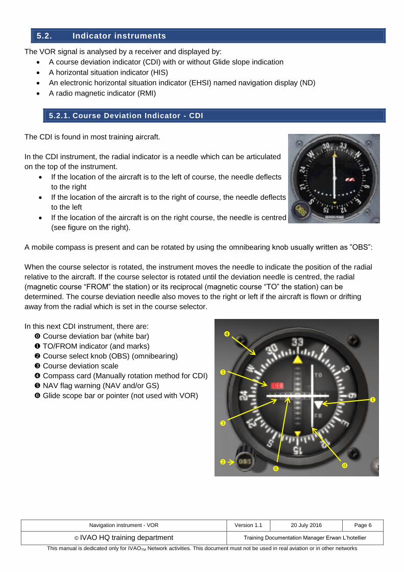
The CDI is found in most training aircraft.
In the CDI instrument, the radial indicator is a needle which can be articulated
on the top of the instrument.
If the location of the aircraft is to the left of course, the needle deflects
to the right
If the location of the aircraft is to the right of course, the needle deflects
to the left
If the location of the aircraft is on the right course, the needle is centred
(see figure on the right).
A mobile compass is present and can be rotated by using the omnibearing knob usually written as ”OBS”:
When the course selector is rotated, the instrument moves the needle to indicate the position of the radial
relative to the aircraft. If the course selector is rotated until the deviation needle is centred, the radial
(magnetic course “FROM” the station) or its reciprocal (magnetic course “TO” the station) can be
determined. The course deviation needle also moves to the right or left if the aircraft is flown or drifting
away from the radial which is set in the course selector.
In this next CDI instrument, there are:
Course deviation bar (white bar)
TO/FROM indicator (and marks)
Course select knob (OBS) (omnibearing)
Course deviation scale
Compass card (Manually rotation method for CDI)
NAV flag warning (NAV and/or GS)
Glide scope bar or pointer (not used with VOR)

Navigation instrument - VOR Version 1.1 20 July 2016 Page 7
© IVAO HQ training department Training Documentation Manager Erwan L’hotellier
This manual is dedicated only for IVAOTM Network activities. This document must not be used in real aviation or in other networks
5.2.2. Horizontal Situation Indicator - HSI
The HSI is an aircraft instrument normally mounted in place of a conventional heading indicator.
It combines a heading indicator with a VOR/ILS display.
On the HSI, the aircraft is represented by a schematic figure in the centre of the instrument – the VOR/ILS
display is shown in relation to this figure. The heading indicator is usually slaved to a remote compass and
the HSI is frequently interconnected with an autopilot capable of following the heading select bug.
In this instrument, there are:
Course deviation bar (white bar)
TO/FROM indicator
Course select knob
Course deviation scale
Compass card (automatic rotation for HSI with heading)
Select course pointer (only for HSI)
Symbolic aircraft (only for HSI)
Heading select knob (only for HSI)
Heading select bug (only for HSI)
NAV (or GS) flag warning
Lubber line (Orange or white)
Lubber line represents the current aircraft flying direction.
The HSI illustrated above is a type designed for smaller airplanes and is the size of a standard 3¼ inch instrument. Airline and jet aircraft HSIs are larger and may include more display elements.
The desired course is selected by rotating the course select knob, in relation to the compass card.
The HSI has a fixed aircraft symbol and the course deviation bar displays the aircraft’s position relative
to the selected course.
The TO/FROM indicator is a triangular pointer:
When the indicator points to the head of the course select pointer, the arrow shows the course
selected. If properly intercepted and flown, the course will take the aircraft to the chosen facility.
When the indicator points to the tail of the course, the arrow shows that the course selected, if
properly intercepted and flown, will take the aircraft directly away from the chosen facility.
On a conventional VOR indicator, left/right and to/from must be interpreted in the context of the selected
course.
When an HSI is tuned to a VOR station,
Left and right always mean left and right
TO/FROM is indicated by a simple triangular arrowhead pointing to the VOR. If the arrowhead
points to the same side as the course selector arrow, it means TO, and if it points behind to the side
opposite the course selector, it means FROM.

Navigation instrument - VOR Version 1.1 20 July 2016 Page 8
© IVAO HQ training department Training Documentation Manager Erwan L’hotellier
This manual is dedicated only for IVAOTM Network activities. This document must not be used in real aviation or in other networks
5.2.3. Electronic HSI
The most modern HSI displays are computed and integrated with electronic flight instrument systems into
dedicated instruments or into "glass cockpit" systems.
Rose Mode E-HSI Arc Mode E-HSI
5.2.4. Radio Magnetic Indicator -RMI
The RMI is a navigational aid providing aircraft magnetic or
directional gyro heading and VOR, GPS, and ADF(for NDB) bearing
information.
The RMI consists of a compass card, a heading index, one or two
bearing pointers, and pointer function switches.
The two pointers are driven by any two combinations of a GPS, an
ADF, and/or a VOR.
The pilot has the ability to select the navigation aid to be indicated. In the figure on the right, the RMI is configured to receive 2 VOR, 2 NDB (ADF) or combinations of one VOR and one NDB.
Note that there is no course with the RMI. RMI will work like an ADF.
Figure represents dual-RMI with 2 bearing pointers.
Navigation instrument - VOR Version 1.1 20 July 2016 Page 9
© IVAO HQ training department Training Documentation Manager Erwan L’hotellier
This manual is dedicated only for IVAOTM Network activities. This document must not be used in real aviation or in other networks
6. VOR to determine position of the aircraft
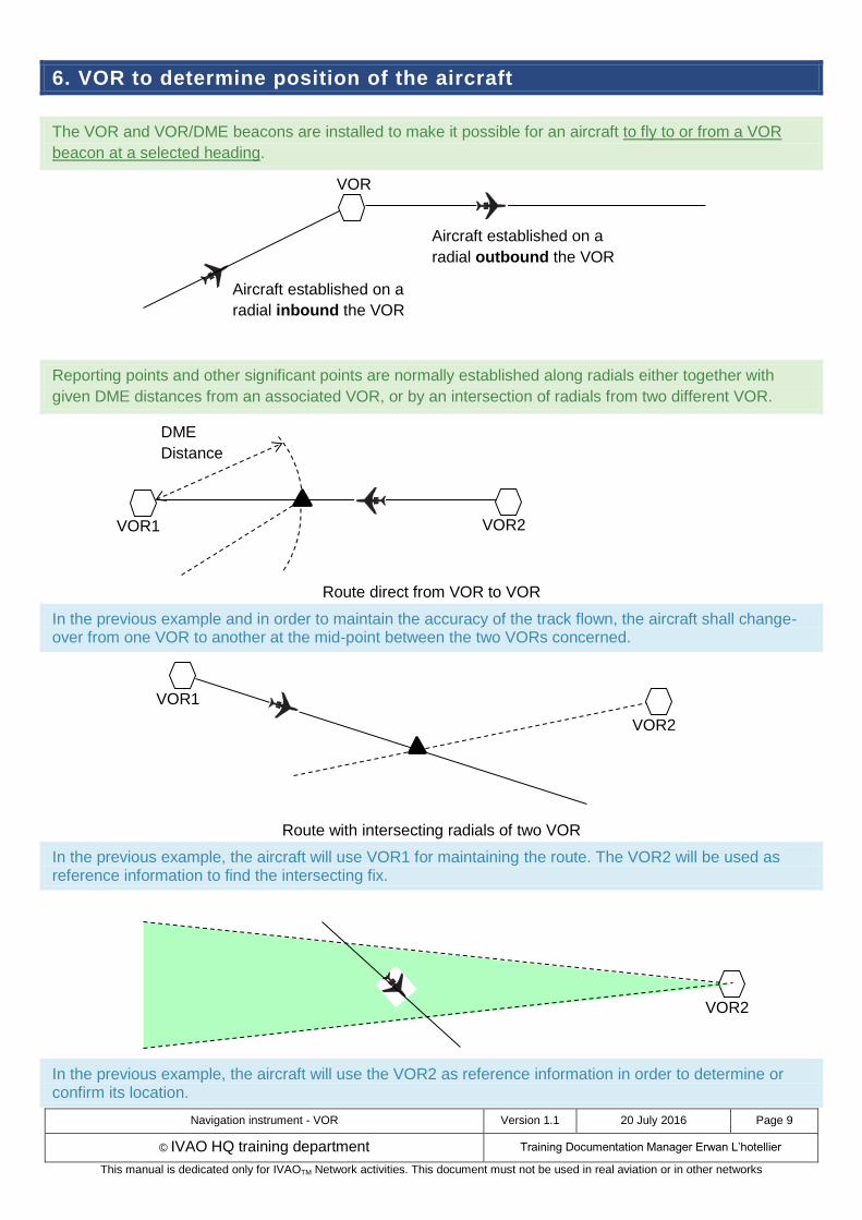
The VOR and VOR/DME beacons are installed to make it possible for an aircraft to fly to or from a VOR
beacon at a selected heading.
Reporting points and other significant points are normally established along radials either together with
given DME distances from an associated VOR, or by an intersection of radials from two different VOR.
Route direct from VOR to VOR
In the previous example and in order to maintain the accuracy of the track flown, the aircraft shall change-over from one VOR to another at the mid-point between the two VORs concerned.
Route with intersecting radials of two VOR
In the previous example, the aircraft will use VOR1 for maintaining the route. The VOR2 will be used as reference information to find the intersecting fix.
In the previous example, the aircraft will use the VOR2 as reference information in order to determine or confirm its location.
Aircraft established on a
radial outbound the VOR
Aircraft established on a
radial inbound the VOR
VOR1 VOR2
VOR1
VOR2
VOR
DME
Distance
VOR2
Navigation instrument - VOR Version 1.1 20 July 2016 Page 10
© IVAO HQ training department Training Documentation Manager Erwan L’hotellier
This manual is dedicated only for IVAOTM Network activities. This document must not be used in real aviation or in other networks
7. CDI instrument reading
In this chapter, we present the basic of CDI instrument reading and use.
7.1. TO/FROM Region
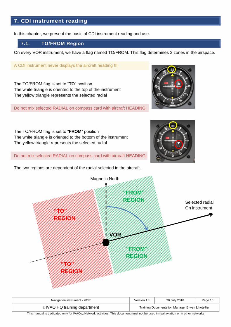
On every VOR instrument, we have a flag named TO/FROM. This flag determines 2 zones in the airspace.
A CDI instrument never displays the aircraft heading !!!
The TO/FROM flag is set to “TO” position
The white triangle is oriented to the top of the instrument
The yellow triangle represents the selected radial
Do not mix selected RADIAL on compass card with aircraft HEADING.
The TO/FROM flag is set to “FROM” position
The white triangle is oriented to the bottom of the instrument
The yellow triangle represents the selected radial
Do not mix selected RADIAL on compass card with aircraft HEADING.
The two regions are dependent of the radial selected in the aircraft.
Magnetic North
VOR
Selected radial
On instrument “TO”
REGION
“FROM”
REGION
“TO”
REGION
“FROM”
REGION

Navigation instrument - VOR Version 1.1 20 July 2016 Page 11
© IVAO HQ training department Training Documentation Manager Erwan L’hotellier
This manual is dedicated only for IVAOTM Network activities. This document must not be used in real aviation or in other networks
These region definitions are independent of the heading. The TO/FROM indication is not enough to
determine if you fly to the beacon or from the beacon.
By centering the needle, the course selector indicates either the course “FROM” the station or the course
“TO” the station.
If the flag displays a “TO”, the course shown on the course selector will be flown to the station.
If the flag displays a “FROM”, the course shown on the course selector will be flown away from the
station.
7.2. CDI reading in function of region
On a CDI instrument, the pilot will turn the OBS knob to the desired radial (070° in our example).
We suppose that the aircraft is on the heading 070° (same orientation with the radial).
The CDI will react as the figure below in function of the TO/FROM zone.
VOR
Radial =70°
“TO”
REGION
“FROM”
REGION
Magnetic North
Navigation instrument - VOR Version 1.1 20 July 2016 Page 12
© IVAO HQ training department Training Documentation Manager Erwan L’hotellier
This manual is dedicated only for IVAOTM Network activities. This document must not be used in real aviation or in other networks
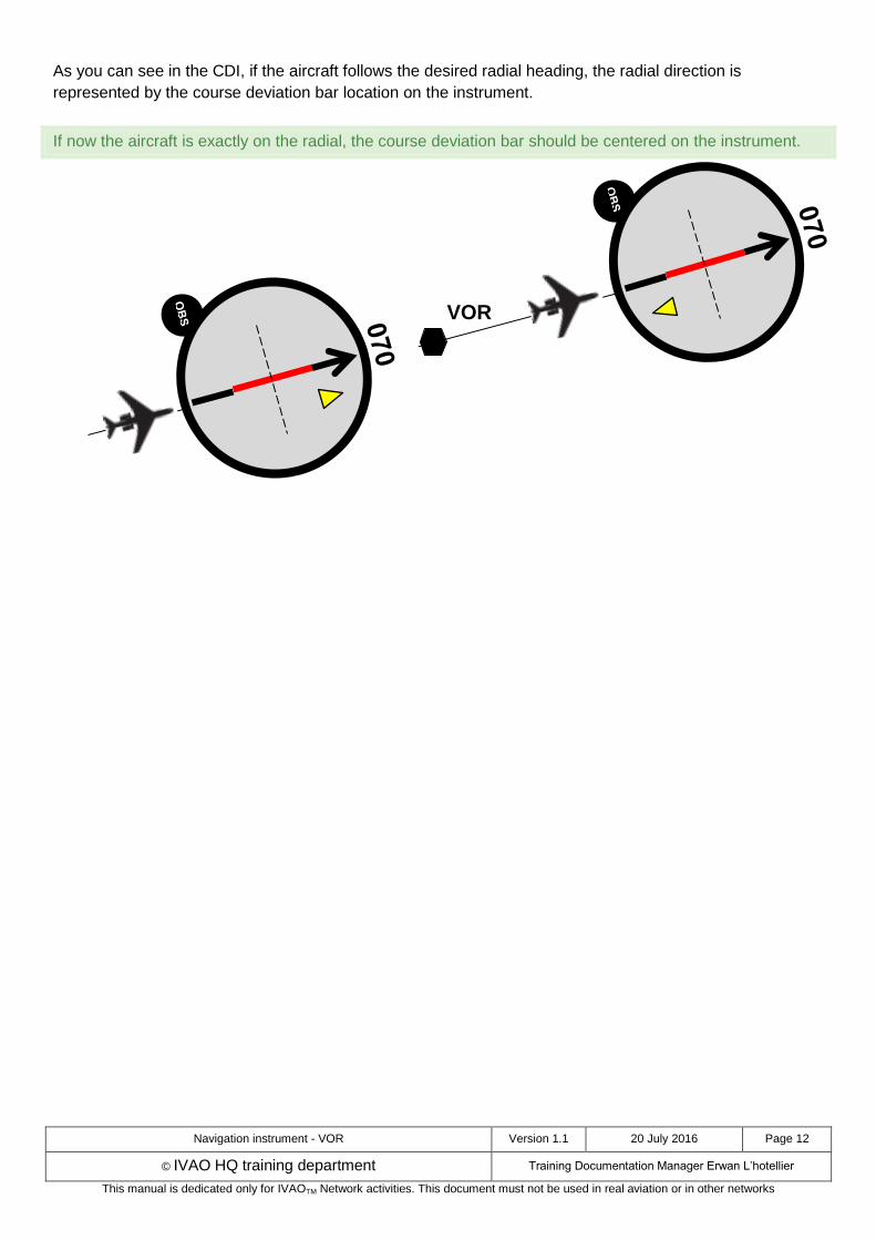
As you can see in the CDI, if the aircraft follows the desired radial heading, the radial direction is
represented by the course deviation bar location on the instrument.
If now the aircraft is exactly on the radial, the course deviation bar should be centered on the instrument.
VOR
Navigation instrument - VOR Version 1.1 20 July 2016 Page 13
© IVAO HQ training department Training Documentation Manager Erwan L’hotellier
This manual is dedicated only for IVAOTM Network activities. This document must not be used in real aviation or in other networks
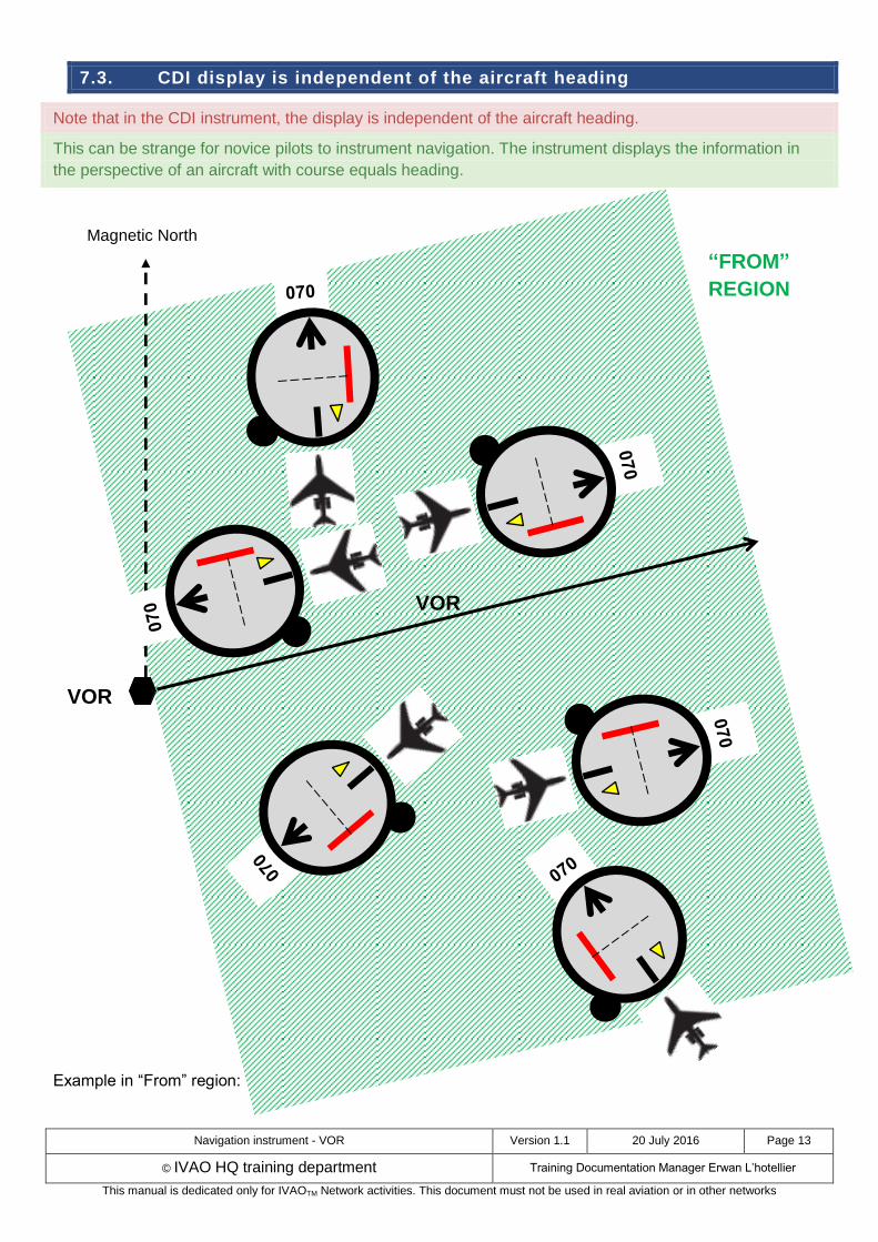
7.3. CDI display is independent of the aircraft heading
Note that in the CDI instrument, the display is independent of the aircraft heading.
This can be strange for novice pilots to instrument navigation. The instrument displays the information in
the perspective of an aircraft with course equals heading.
Example in “From” region:
VOR
“FROM”
REGION
Magnetic North
VOR
Navigation instrument - VOR Version 1.1 20 July 2016 Page 14
© IVAO HQ training department Training Documentation Manager Erwan L’hotellier
This manual is dedicated only for IVAOTM Network activities. This document must not be used in real aviation or in other networks
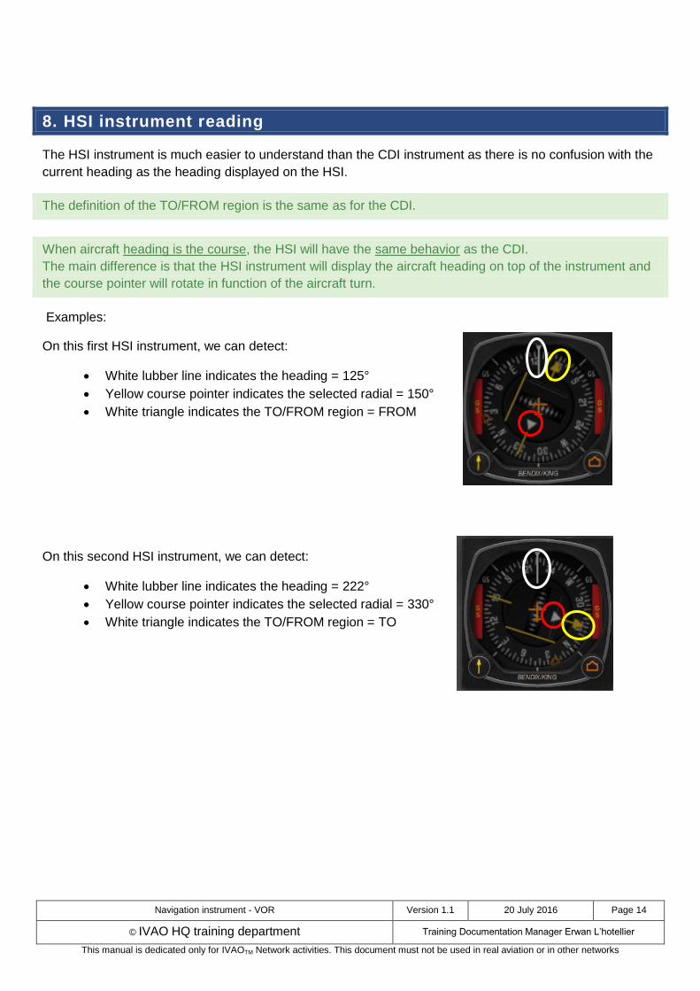
8. HSI instrument reading
The HSI instrument is much easier to understand than the CDI instrument as there is no confusion with the
current heading as the heading displayed on the HSI.
The definition of the TO/FROM region is the same as for the CDI.
When aircraft heading is the course, the HSI will have the same behavior as the CDI.
The main difference is that the HSI instrument will display the aircraft heading on top of the instrument and
the course pointer will rotate in function of the aircraft turn.
Examples:
On this first HSI instrument, we can detect:
White lubber line indicates the heading = 125°
Yellow course pointer indicates the selected radial = 150°
White triangle indicates the TO/FROM region = FROM
On this second HSI instrument, we can detect:
White lubber line indicates the heading = 222°
Yellow course pointer indicates the selected radial = 330°
White triangle indicates the TO/FROM region = TO
Navigation instrument - VOR Version 1.1 20 July 2016 Page 15
© IVAO HQ training department Training Documentation Manager Erwan L’hotellier
This manual is dedicated only for IVAOTM Network activities. This document must not be used in real aviation or in other networks
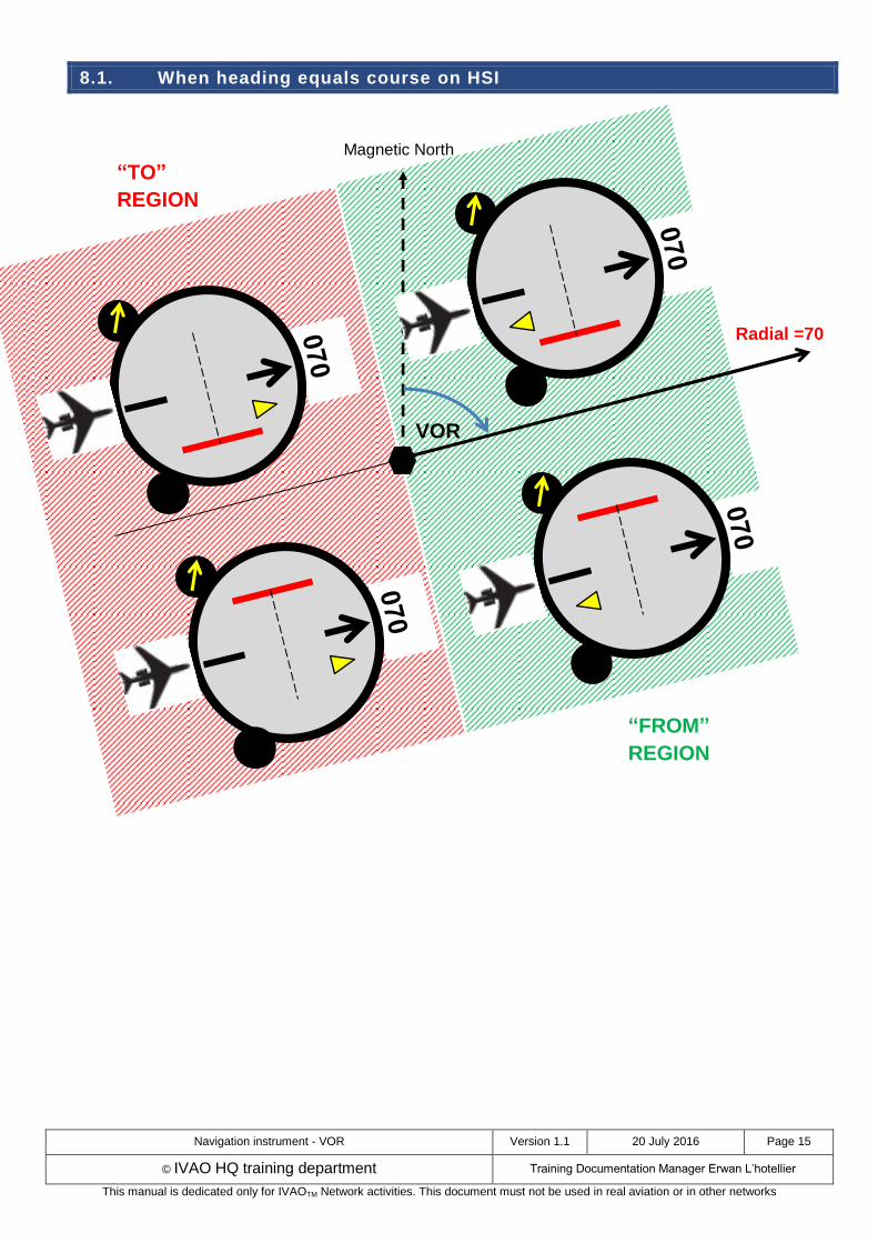
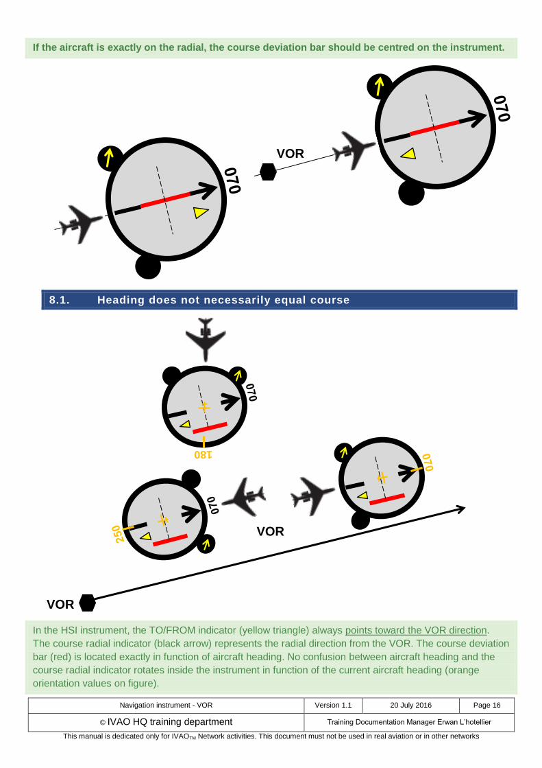
8.1. When heading equals course on HSI
VOR
Radial =70
“TO”
REGION
“FROM”
REGION
Magnetic North
Navigation instrument - VOR Version 1.1 20 July 2016 Page 16
© IVAO HQ training department Training Documentation Manager Erwan L’hotellier
This manual is dedicated only for IVAOTM Network activities. This document must not be used in real aviation or in other networks
If the aircraft is exactly on the radial, the course deviation bar should be centred on the instrument.
8.1. Heading does not necessarily equal course
In the HSI instrument, the TO/FROM indicator (yellow triangle) always points toward the VOR direction.
The course radial indicator (black arrow) represents the radial direction from the VOR. The course deviation
bar (red) is located exactly in function of aircraft heading. No confusion between aircraft heading and the
course radial indicator rotates inside the instrument in function of the current aircraft heading (orange
orientation values on figure).
180
VOR
VOR
VOR
Navigation instrument - VOR Version 1.1 20 July 2016 Page 17
© IVAO HQ training department Training Documentation Manager Erwan L’hotellier
This manual is dedicated only for IVAOTM Network activities. This document must not be used in real aviation or in other networks
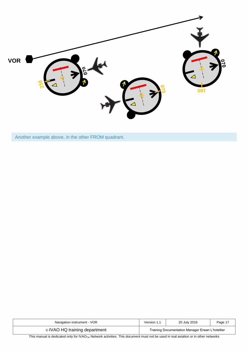
Another example above, in the other FROM quadrant.
VOR
180

Navigation instrument - VOR Version 1.1 20 July 2016 Page 18
© IVAO HQ training department Training Documentation Manager Erwan L’hotellier
This manual is dedicated only for IVAOTM Network activities. This document must not be used in real aviation or in other networks
9. Where is the VOR and shortest distance to join the radial ?
Using a CDI or an HSI, you must know as a pilot where the VOR is and which is the shortest path to reach
it.
The VOR is located in the sector determined by the TO/FROM flag in the direction of the radial and the
shortest path in direction to the radial.
The shortest path can be determined by the direction from the centre of the instrument towards the course
deviation bar. On the CDI instrument just read the number displayed on the compass card (±90° of the
radial).
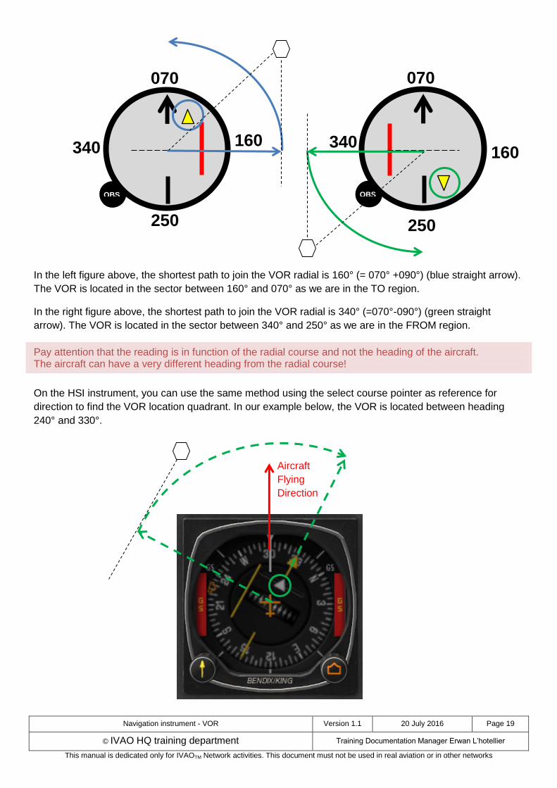
In the left figure above, the shortest path to join the VOR radial is 340° (=070°-090°) (blue straight arrow).
The VOR is located in the sector between 340° and 070° as we are in the TO region.
In the right figure above, the shortest path to join the VOR radial is 160° (= 070° +090°) (green straight
arrow). The VOR is located in the sector between 160° and 250° as we are in the FROM region.
250 250
160 160 340
340
070
OBS
070
OBS
Navigation instrument - VOR Version 1.1 20 July 2016 Page 19
© IVAO HQ training department Training Documentation Manager Erwan L’hotellier
This manual is dedicated only for IVAOTM Network activities. This document must not be used in real aviation or in other networks
In the left figure above, the shortest path to join the VOR radial is 160° (= 070° +090°) (blue straight arrow).
The VOR is located in the sector between 160° and 070° as we are in the TO region.
In the right figure above, the shortest path to join the VOR radial is 340° (=070°-090°) (green straight
arrow). The VOR is located in the sector between 340° and 250° as we are in the FROM region.
Pay attention that the reading is in function of the radial course and not the heading of the aircraft. The aircraft can have a very different heading from the radial course!
On the HSI instrument, you can use the same method using the select course pointer as reference for
direction to find the VOR location quadrant. In our example below, the VOR is located between heading
240° and 330°.
250
160 340
250
160 340
070
OBS
070
OBS
Aircraft
Flying
Direction