navigation accuracy for infrared equipped apollo … technical note w -i i m 0 h t m z a % + m 4 2e...
TRANSCRIPT

N A S A TECHNICAL NOTE
-Iw I
M 0 h T m
A z %+ m
24 Er/l 4 z
NAVIGATION ACCURACY FOR INFRARED EQUIPPED APOLLO AIRCRAFT FOR REENTRY TRACKING
. by F. K d i l
. Goddard Spdce Flight Center Greenbelt, M d
1. i $:,//'
N A T I O N A L AERONAUTICS AND SPACE A D M I N I S T R A T I O N 0 W A S H I N G T O N , D. C. 0 fiOVEh-B'ER 1 9 6 6
https://ntrs.nasa.gov/search.jsp?R=19660030248 2018-07-06T23:01:09+00:00Z

NAVIGATION ACCURACY FOR INFRARED EQUIPPED
APOLLO AIRCRAFT FOR REENTRY TRACKING
By F. Kalil
Goddard Space Flight Center Greenbelt , Md.
,
N A T I O N A L AERONAUTICS AND SPACE ADMINISTRATION
For sale by the Clearinghouse for Federal Scientific and Technical Information Springfield, Virginia 22151 - Price $2.00

ABSTRACT
In this work the navigational accuracy requirements were analyzed for an Apollo reentry aircraft equipped with an infrared acquisition and tracking system (IRATS) for monitoring the reentry of the Apollo Command Module. The navigational accuracy requirements are functionally dependent on detection and tracking range, and pointing accuracy; which in turn a r e functionally dependent on many factors, some of which are: detector size, number of detectors, dwell time, scan rate, search field, optical system focal length and aperture size, detection probability, false alarm rates, and thermal characteristics of the reentering spacecraft. Thus, it was believed necessary to investigate these parameters in order to make the necessary trade-offs and come up with some realistic requirements. This was done by analyzing some conceptual designs which could fulfill the requirements set forth in Reference 1 regarding acquisition time, detection range, probability of detection, and pointing accuracy. It was concluded that the navigational accuracy of the IRATS equipped aircraft should be about 2 n.mi. ( 1 ~ )on each the latitude and longitude, assuming a negligible altitude error .
ii
1

CONTENTS
Abstract . . . . . . . . . . . . . . . . . . . . . . . . . . . . . . . ii
INTRODUCTION . . . . . . . . . . . . . . . . . . . . . . . . . 1
ANALYSIS . . . . . . . . . . . . . . . . . . . . . . . . . . . . . 2
Angular Pointing Data From One Aircraft . . . . . 4
Angular Pointing Data From Two Aircraft . . . . . 6
Other Design Considerations for the IRATS . . . . 9
CONCLUSIONS . . . . . . . . . . . . . . . . . . . . . . . . . . 29
References . . . . . . . . . . . . . . . . . . . . . . . . . . . . . 30
iii

NAVIGATION ACCURACY FOR INFRARED EQUIPPED APOLLQ AIRCRAFT FOR REENTRY TRACKING
b Y F. Kalil
Goddard Space Flight Center
INTRODUCTION
Considerable work has been done in the past regarding the use of an infrared system for acquiring and tracking the Apollo spacecraft during reentry (References 1through 6). For purposes of completeness, some of what has been reported may be repeated here primarily to provide a unified and coherent report for the benefit of the reader.
During reentry into 'the atmosphere (Figure l),the Apollo Command Module (Figure 2) becomes heated due to the frictional effects, causing large amounts of energy to be dissipated. Much of this energy is radiated in the form of electromagnetic radiation in both the visible and infrared wavelength regions. Some typical temperature characteristics for the reentering Apollo Command Module (C/M), and the spectral irradiance curves for some of these temperatures for a black body are shown in Figures 3 and 4,respectively. However, it is expected that the Apollo C/M will be a gray body, with an emmissivity of about 0.75, instead of a black body.
400
2 300 0
0 Y
= 200 u-D2 c 3 1004
0 2,000 1,500 1,000 500 0
RANGE TO GO (n. mi.) I I I I I I d
35.0 27.8 21.5 21.2 20.8 15.0 0.6
VELOCITY (103 fps) I I 10 loo 200 300 400 500 700
REENTRY TIME (rec)
Figure 1 -Possible Apol lo reentry trajectory.
S - DISTANCE ALONG THE SURFACE FROM THE GEOMETRIC CENTER OF THE SPHERICAL HEAT SHEILD.
R-MAXIMUM BODY RADIUS OF THE COMMAND MODULE,
INCHES FULL SCALE.
I 33\
R=184.8 IN.!/
R = i . / IN. I 142.5 IN..
Figure 2-Basic configuration of Apollo Command Module.
L

'I
I Y
10-2
300 400 500 0.5 1 5 10 50 100
TIME (secs) WAVELENGTH A (microns)
Figure 4-Spectral radiant emittance of a black body as Figure 3-Apollo C/M heating rate and temperature. a function of wavelength and temperature.
If the spacecraft reenters during darkness, the hot radiating body may be seen quite readily. If, however, the spacecraft reenters during daylight as is presently planned for all manned spaceflights, namely Gemini, Apollo, etc., then the visible radiation emitted by the spacecraft would be very difficult to detect against the daylight background. Furthermore, during certain phases of the reentry, the spacecraft is in a communication blackout due to the hot plasma ion sheath surrounding it, as shown in Figure 1. Since the Apollo is a maneuverable spacecraft, it would be difficult to predict i ts position based on a priori knowledge. Thus, an infrared acquisition and tracking system, which can be used on board highly mobile aircraft above the largest portion of cloud cover, becomes increasingly important. Such a system would be valuable in seeking, acquiring, and tracking the spacecraft particularly during blackout, and thus facilitate a successful recovery of the spacecraft and more importantly its crew.
The purpose of this report is to present the navigational accuracy for infrared equipped Apollo aircraft for reentry tracking. In order to do this it is helpful to understand the Infrared Acquisition and Tracking System (IRATS), its use, its characteristics, and some of the detailed design considerations such as detector dimensions, focal length, and instantaneous field of view as they relate to pointing accuracy. The pointing accuracy will have a bearing on the navigational accuracy requirements. Therefore, some of these factors will also be discussed in this report.
ANALYSIS
As pointed out above, the concept of an infrared acquisition and tracking system (IRATS) was investigated, and it was found to be useful for acquiring the reentering craft and providing angular tracking data relative to the aircraft (Reference 1). The angular pointing data would be useful for:
1. Pointing and slaving the aircraft 's Unified S-Band communication antenna.
2. Rough trajectory calculations in real time to assist in a safe recovery of the spacecraft and more importantly its crew. (Figures 11, 12, and 13 of Reference 1; also, Figures 5 and 6.)
3. Providing useful data for post flight analyses.
2

HORIZON : c Z 1' SAMPLING RATE: 2 MEAS/SEC TRACKER LOCATION ERRORS:
6(LAT. )= l n . m i . (2km) 6 (LONG. )= l n . m i . ( 2 Ian) 6 (ALTITUDE)=O
TRACKER ERRORS :
Sa= 6 e = *5 X RADIANS
ASSUMES KNOWLEDGE OF EQUATIONS OF MOTION
10
1 1 1 1 I I l I 40 80 120 160 200
The Infrared Acquisition and Tracking System (IRATS) must be capable of monitoring both
HORIZON: t >lo SAMPLING RATE: 2 MEAS/SEC TRACKING LOCATION ERRORS:
6(Lat.) = 1 n . m i . ( 2 k m ) 6 (Long. ) = 1 n . mi. (2 km) 6 (Altitude) = 0
TRACKERERRORS: Sa = 6 e =f.5 x 10 - 3 mdians
10 ASSUMES NO 0'
n c
0.1-0I1 ~~
I 1 -I I I I I I 20040 80 120 160
TRACKING TIME (secs)
Figure 6-Propagation of errors in spacecraft position for reentry tracking with two aircraft equipped with I RATS.
a nominal as well as an emergency reentry [reentry refers to the initial reentry into the earth's atmosphere as well as any subsequent reentry resulting from a skip-out after the initial reentry (Figures 1, 2, 3 and 5 of Reference 7)]. Furthermore, it appears likely that the heading of the Apollo/Range Instrumented Aircraft would not always be advantageously pointed to facilitate acquisition of the reentering spacecraft. Therefore, one of the IRATS requirements is that it shall be capable of scanning the hemisphere in order to ensure acquisition of the reentering spacecraft.
In the following paragraphs, the method(s) of utilizing the angular pointing data and the corresponding problems are investigated.
3

Angular Pointing Data From One Aircraft
The angular pointing data from one aircraft could be used as follows:
Pointing and Slaving of Aircraft's Communication Antenna- This in itself poses some interesting problems. Mr. J. R. Moore (Reference 6) has made some recommendations regarding the configuration and location of the Unified S-Band System (USBS) antenna which is not presently specified but is presently being investigated as par t of the Program Definition Phase Contract for the Apollo Range Instrumented Aircraft. The same antenna will be used for the VHF communication link. The USBS is the primary communication link to the C/M. It is the writer's understanding that the VHF link is the primary telemetering link to the SIVB during the injection phase of a lunar mission, and that this VHF would also serve as a back-up for the USBS link to the C/M. The angles through which the USBS antenna could be pointed relative to the aircraft frame will be part of the specifications for the Program Definition Phase Contract.
As pointed out before, the aircraft heading might not always be advantageously pointed for acquiring the reentry spacecraft. Even in the case of a nominal reentry, the aircraft equipped with an IRATS would fly in a pre-specified flight pattern and in a pre-selected area where the cloud cover would not be expected to present an unduly severe handicap. This is one of the reasons for requiring that the IRATS have the hemispherical scan capability.
Should the aircraft be headed in a disadvantageous direction when the IRATS acquires the spacecraft, it is conceivable that the communication antenna with its limited angular mobility could not point at the spacecraft without the aircraft doing some maneuvering. Hence, the aircraft's maneuverability needs to be considered. The aircraft maneuvering time may be long relative to the time the spacecraft is in the field of view of the IRATS, and it may not always be possible to get the communication antenna pointed at the spacecraft.
The angular pointing accuracies required from the IRATS in order to point the aircraft communication antenna are not at all stringent because of the relatively broad antenna beamwidth (-5" at S-Band) which is expected. Therefore, the pointing accuracy requirements a re based on more stringent requirements to be discussed below and which are within the state-of-the-art.
Rough Trajectory Analyses in Real Time to Facilitate an Effective Recovery of the Spacecraft and More Importantly Its Crew- This facet of the problem has been investigated and is reported in Reference 1. Hence, the following discussion will be very brief.
Any computations o r predictions of the spacecraft trajectory based on angular measurements from one aircraft equipped with an IRATS will be rough, primarily because: .
1. The number of independent measurements obtainable from the IRATS with reasonable accuracy a re basically the azimuth and elevation angles of the slant range vector from the aircraft to the spacecraft.
2. The various parameters entering into the equations of motion of a lifting body type of spacecraft (angle of attack, roll, pitch, yaw, and altitude) cannot be assumed to be known,
4

I I 1 111 I I I 1
particularly during communication black-out. The altitude is mentioned because it is needed to determine the atmospheric density which determines the drag and lift forces on the spacecraft.
It should be pointed out that the magnitude of the slant range might be estimated from the target signal strength in the IRATS by monitoring the signal voltage at the decision-making point in the IRATS circuitry or by allowing an operator to estimate the traget intensity on a visual display screen. Monitoring the signal voltage would be preferable since this data can be recorded on a strip chart recorder and telemetered to the ground station or reentry ship where the necessary computations can readily be made.
The above range estimate may be computed (Reference 5) by applying: (1)Plank's law of radiation to compute the irradiance of the target over the wavelength region of interest ( - 3 . 4 ~to - 5 . 3 , ~for an indium antimonide detector, a type of detector with the fast response time sec which is needed to give the hemispherical coverage and acquisition probabilities within the specified times). In this case the target's temperature and thermal characteristics must be known. (2) The inverse square law which states that the intensity of radiation received by the IRATS is inversely proportioned to the square of the slant range from the target to the detector. In addition, the detector sensitivity (or noise equivalent flux density) and atmospheric attenuation must be taken into account. The detector sensitivity is assumed to include such factors as optical efficiency, signal conversion efficiency, aperture diameter, scanning rate, number of detectors, etc. More will be said about such considerations later on in this report.
It may be expected that the estimated range obtained in the above manner could be wrong by a factor of about three primarily because of uncertainties in the spacecraft's temperature profile and its physical orientation, namely the aspect angle relative to the IRATS.
It has been shown (Reference 1) that with only one aircraft tracking the spacecraft, after acquisition has been effected, the spacecraft position e r r o r is as shown in Figure 5. Values of *5 mrad were used for the IRATS angular errors , which is the overall pointing e r ro r and includes the platform e r r o r s as well as the pointing e r r o r s of the IRATS relative to the platform. These platform e r r o r s a re the uncertainties in the attitude and heading of the IRATS mount as might be provided by an inertial platform and navigation system.
Other assumptions used in arriving at Figure 5 include:
1. The aircraft position e r r o r s on each horizontal axis is k2 km (or 1.08 n.mi.).
2. The aircrdt altitude e r r o r is negligible, which is a reasonable assumption for purposes of this study, particularly if the aircraft is equipped with a radio-altimeter.
3. The IRATS provides angular tracking data every 2 sec, which is conservative, because as stated in Reference 1, the IRATS could provide angular tracking data at a sampling rate of 10 to 20 times per second, particularly in the track mode where the spacecraft image is kept focused on a single detector element. If one uses the higher sampling rates, then the spacecraft position e r r o r s shown in Figure 5 may be reduced by a factor of 2 to 3 (Reference 1).
5

To properly interpret Figure 5, it should be pointed out that the dotted line assumes no a priori knowledge of the equations of motion, while the solid line assumes a knowledge of the equations of motion. The practical case lies somewhere between these two extremes.
Angular Pointing Data From T w o Aircraft
The spacecraft position could be monitored by triangulating the angular pointing data obtained from more than one aircraft simultaneously. Although this mode of operation is not presently recommended because of the operational complexities, it should be mentioned. A knowledge of the spacecraft's position, particularly during blackout, could be used for:
1. Pointing the reentry ship's tracking and communication antennas fo r both skin tracking during blackout and immediate radio contact with the spacecraft at the termination of the blackout.
2. Providing useful real time trajectory data which would be more accurate than the rough trajectory calculations based on angular tracking data from only one aircraft, assuming the aircraft positions are adequately known.
3. Providing useful data for post flight analysis.
The accuracy of the trajectory calculations o r spacecraft position data discussed above depend upon how well the aircraft positions are known. For example, it could be assumed that the spacecraft position e r r o r should be comparable to the spacecraft's on-board navigation capabilities and/or could be within the reentry ship tracking system's circular scan beamwidth to ensure quick acquisition and skin tracking during the ion plasma blackout. Based on these assumptions, a par-
D3..
AIRCRAFT 2 e =ELEVATION ANGLE OF SLANT RANGE VECTORf a=AZIMUTH ANGLE OF SLANT RANGE VECTOR
Se,Sa=ERRORS IN e AND a Sp=POSITION ERROR ON EACH AXIS
D,,D2,D3 =ERROR VOLUME DIMENSIONS t,b3 =RADAR HALF BEAMWIDTH
1. ALTITUDE ERRORS ARE ASSUMED TO BE NEGLIGIBLE COMPARED TO THE OTHER ERRORS
Figure 7-Top view of tracking geometry using two aircraft equipped with IRATS for determining spacecraft position and/or slaving the reentry ship's radar.
ameteric study was made in order to ascertain the trade-offs between the angular pointing accuracies of the IRATS and the aircraft navigation requirements.
Shown in Figures 7 and 8 is the tracking geometry which was used in the following analysis.
From Figure 7, it can be seen that, assuming a normal distribution,
= spacecraft position e r r o r using I -R angular tracking from two aircraft,
where the D1,D,, D, are the axes of the e r r o r volume.
6

In order to simplify the mathematics and to facilitate a parametric analysis, the following assumptions were used:
1.
2.
3.
4.
5.
6.
The range (R) of the spacecraft to Aircraft 1 is larger than its range to Aircraft 2, i.e., R, > R , so that D, > D 2 ,
and hence D should be replaced by D, to be conservative.
The angular pointing e r r o r s from the two aircraft are equal, i.e., SU, Saz
and S E , = 8 e Z .
The azimuth and elevation angular e r r o r s are equal, i.e., Sa = S E .
The aircraft latitude and longitude position e r r o r s ( 8 p ) are all equal so that SP, = FP,.
The aircraft utilizes a radio-altimeter, and the altitude e r r o r s a r e negligible compared to the other e r r o r s involved.
The distribution is normal,
1 . ALTITUDE ERRORS ARE ASSUMED TO BE
2. a , E ARE THE AZIMUTH AND ELEVATION ANGLES, RESPECTIVELY.
3. & , S I ARE THE ERRORS IN THE AZIMUTH AND ELEVATION ANGLES.
4. Sp I S THE POSITION ERROR O N EACH AXIS. 5. R IS THE SLANT RANGE VECTOR. 6. $ I S THE SHIP TRACKER BEAM WIDTH IN A
SPIRAL OR CIRCULAR SCAN MODE, 7. THE D ‘ s ARE THE AXES OF THE SPACECRAFT
ERROR VOLUME.
Figure 8-Top view of tracking geometry using two aircraft equipped with IRATS for determining spacecraft position and/or slaving the reentry ship’s radar.
Based on these simplifying and probably conservative assumptions, it can be seen from Figu r e 7 that
and
D,’ = 4[(R, S E , ) ~+ (Sp, s in< , ) ‘ ] . (4)
Substituting from Equations 2, 3, and 4 into Equation 1 and using the above assumptions, then .
Now the problem reduces to one of assessing the allowable aircraft position e r r o r s (SP), Le., the aircraft navigation requirements as a function of some realistic o r practical values for both
7
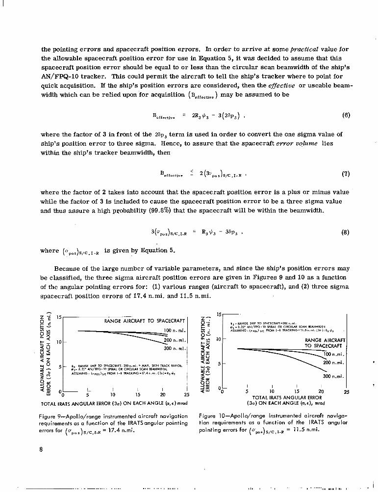
the pointing e r r o r s and spacecraft position errors . In order to arr ive at some pactical value for the allowable spacecraft position e r ror for use in Equation 5, it was decided to assume that this spacecraft position e r r o r should be equal to o r less than the circular scan beamwidth of the ship's AN/FPQ-10 tracker. This could permit the aircraft to tell the ship's tracker where to point for quick acquisition. If the ship's position e r r o r s a r e considered, then the eflective o r useable beam-width which can be relied upon for acquisition ( Beffective) may be assumed to be
where the factor of 3 in front of the 26p3 t e rm is used in order to convert the one sigma value of ship's position e r ror to three sigma. Hence, to assure that the spacecraft e w o r volume lies within the ship's tracker beamwidth, then
where the factor of 2 takes into account that the spacecraft position e r r o r is a plus or minus value while the factor of 3 is included to cause the spacecraft position e r r o r to be a three sigma value and thus assure a high probability (99.8%) that the spacecraft will be within the beamwidth.
where (Dpos)S/C.I-R is given by Equation 5.
Because of the large number of variable parameters, and since the ship's position e r rors may be classified, the three sigma aircraft position e r r o r s a r e given in Figures 9 and 10 as a function of the angular pointing e r rors for: (1)various ranges (aircraft to spacecraft), and (2) three sigma spacecraft position e r rors of 17.4 n.mi. and 11.5 n.mi.
RANGE AIRCRAFT TO SPACECRAFT l5 II R -RANGE SHIP TO SPACfCRAFT=lWn.mi.$: I3.35. AN/FPQ-10 SPIRAL OR CIRCULAR SCAN BEAMWID7H ASSUMING: FROM I - R TRACKlNG=I1.5n.mi.(30)=R1*, .
10t RANGEAIRCRAFTI 300 n . mi. TO SPACECRAFT
R - RANGE SHIP TO SPACECWFT=IWn.mi. MAX. SKIN TRACK RANGE. 5 200 n.mi. .
3.35. AN/FPQ-IO SWRAL OR CIRCULAR SCAN W W I D T H . ASSUMING: ( O ~ ~ ~ ) ~ ~ ~ F R O MI - R TRACKING=17.4n.mi. ( 3 e ) = R 3 S 3
300 n.mi.
I I 1 I I l l 1 I
5 10 15 20 25 OO 5 10 15 20 25 TOTAL IRATS ANGULAR ERROR
TOTAL IRATS ANGULAR ERROR (30)ON EACH ANGLE (a,�) mmd (3a)ON EACH ANGLE (a,�), mrad
Figure 9--ApoIIo/range instrumented aircraft navigation Figure 10-Apollo/range instrumented aircraft naviga
requirements as a function of the IRATSangular pointing tion requirements as a function of the IRATS angular
errors for ( o ~ ~ ~ ) ~ / ~ , ~ - ~ pointing errors for ups S/C,I-R = 11.5 n.mi.= 17.4 n.mi. 0 8
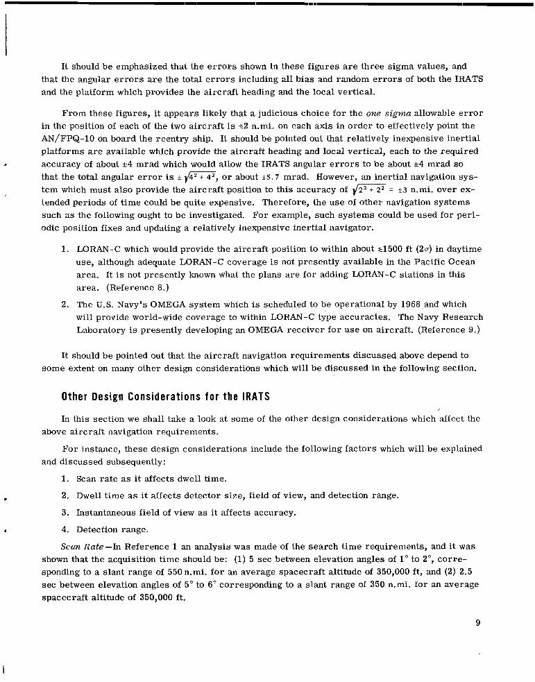
It should be emphasized that the e r r o r s shown in these figures are three sigma values, and that the angular e r r o r s a r e the total e r r o r s including all bias and random e r r o r s of both the IRATS and the platform which provides the aircraft heading and the local vertical.
From these figures, it appears likely that a judicious choice for the one sigma allowable e r r o r in the position of each of the two aircraft is *2 n.mi. on each axis in order to effectively point the AN/FPQ-10on board the reentry ship. It should be pointed out that relatively inexpensive inertial platforms are available which provide the aircraft heading and local vertical, each to the required accuracy of about *4 mrad which would allow the IRATS angular e r r o r s to be about *4 mrad so that the total angular e r r o r is * i4--, or about t 5 . 7 mrad. However, an inertial navigation system which must also provide the aircraft position to this accuracy of {m= 3 3 n.mi. over extended periods of time could be quite expensive. Therefore, the use of other navigation systems such as the following ought to be investigated. For example, such systems could be used for periodic position fixes and updating a relatively inexpensive inertial navigator.
1. LORAN-C which would provide the aircraft position to within about 51500 f t (20) in daytime use, although adequate LORAN-C coverage is not presently available in the Pacific Ocean area. It is not presently known what the plans a r e for adding LORAN-C stations in this area. (Reference 8.)
2. The U.S. Navy's OMEGA system which is scheduled to be operational by 1968 and which will provide world-wide coverage to within LORAN-C type accuracies. The Navy Research Laboratory is presently developing an OMEGA receiver for use on aircraft. (Reference 9.)
It should be pointed out that the aircraft navigation requirements discussed above depend to some extent on many other design considerations which will be discussed in the following section.
Other Design Considerations for the IRATS
In this section we shall take a look at some of the other design considerations which affect the above aircraft navigation requirements.
For instance, these design considerations include the following factors which will be explained and discussed subsequently:
1. Scan rate as it affects dwell time.
2. Dwell time as it affects detector size, field of view, and detection range.
3. Instantaneous field of view as it affects accuracy.
4. Detection range.
Scan Rate-In Reference 1 an analysis was made of the search time requirements, and it was shown that the acquisition time should be: (1)5 sec between elevation angles of 1" to 2", corresponding to a slant range of 550n.mi. for an average spacecraft altitude of 350,000 f t , and (2) 2.5 sec between elevation angles of 5" to 6" corresponding to a slant range of 350 n.mi. for an average spacecraft altitude of 350,000 ft .
9
I

l111l1lllllIlllIllllI Ill 1m11ll11llll1111
ORBIT\ This is based on a consideration of the tracking time and angular rates. For instance, shown in Figure 11 is the tracking geometry for an overhead pass. Using the nomenclature in Figure 11 it can be seen that
s i n p - s i n ( � +go") - s i n y ~~ -R - b a - (9)
But
y = 180" - (90" + E ) - ,L3 ,
y = 90 - ( E t p ) . (10)
Therefore,
C E - cos ( E t p ) , b - a
where
a = Re t h,
b = Re t H, a=R.+h b = R,+H h = aircraft altitude, h = AiRCRAFT ALTITUDE H= SPACECRAFT ALTITUDE H = spacecraft altitude, R =SLANT RANGE FROM THE AIRCRAFT TO THE SPACECRAFT R'= SADIUS OF VISIBILITY and
Figure 11-Tracking geometry for an overhesd pass. R = slant range from the aircraft to the spacecraft.
However, p is a small angle which does not exceed about 10"for spacecraft altitudes of less than 100 n.mi., and the spacecraft altitude during reentry is less than 70 n.mi.
Then, in Equation 11, expanding COS ( E t p ) by use of the cosine of the sum of two single formula; using a ser ies expansion for the cos p; dropping te rms of order higher than quadratic; using the quadratic formula to solve for p as a function of E ; assuming circular orbital speed for the spacecraft to get a s a function of Re t H; and integrating ,b dt gives the tracking time
where
and p = 6.275086 x l o 4 n.mi.3/sec2 is the earth's gravitational constant.
10

The tracking time T is shown in Figure 12 as a function of E and is in agreement with the results obtained in Reference 1.
In order to obtain the elevation angular rate i as a function of E , differentiate Equation 11 with respect to time and obtain
; = b a s i n E
b s in ( E + p )
Figure 13 gives i as a function of E , where i is the elevation angular rate of the spacecraft relative to the aircraft.
In existing search and track systems, namely the AVSCAN, produced for military applications (Reference lo), the system tracks while it scans. This feature permits it to detect the target several times and assures discriminating the "real" target from false ones due to background noise. Assuming that the RATS being discussed in this report must scan its search field (2n steradians, a hemisphere) several times to assure a high probability of discrimination of the real target at the lower elevation angles and longer ranges, a judicious choice of the allowable time to scan the hemisphere appears to be 2 seconds. As will subsequently be shown, this scan time appears to be within the present state-of-the-art, and the probability of detection could be about 0.995 with a false alarm rate of sterad at a range of 580 n.mi. and an Apollo C/M body temperature of 1300 K.
10 150
; 9 2
3 8 U v
7.UI
w ' 6d
H=SPACECRAFT ALTITUDE z 5 3
h=AIRCRAFT ALTITUDE =40,000f t ( 3 4Z
25 I u
I I I I I I I I h =AIRCRAFT ALTITUDE 40,000 ft 0 10 20 30 40 50 60 70 80 90
ELEVATION ANGLE E (degrees) 0 10 20 30 40 50 60 70 80 90 100 110 ELEVATION ANGLE ,E (degrees)
Figure 12-Apollo reentry aircraft tracking time versus elevation, assuming acquisition and tracking begin a t Figure 13-Elevation angular rate of spacecraft relative zenith for an overhead pass. eo aircraft versus elevation angle for an overhead pass.
11

scan time (the time required to scan this search field) is 2 sec. In this section the technical implications of such a wide search field with such a fast scan time will be discussed with emphasis on how they affect the IRATS configuration, dwell time, detector size, field of view, and detection range.
Although excellent infrared scan and t rack instruments of the type being discussed presently exist, they were designed to meet requirements different f rom those presented here. However, a simple conceptual design of an IRATS would be helpful to understand the design considerations which are about to be discussed.
Shown in Figures 14 and 15 is a conceptual design of an IRATS which could give the hemispherical scan in 2 sec and provide the desired field of view and sensitivity (or detection range). Figure 14 is a simple diagram of the system while Figure 15 is a three dimensional picture of what the system might look like. Figure 16 shows an alternate conceptual design, and Figure 17 is a three dimensional picture of Figure 16. As shown in Figure 14, one mirror (Mirror A) would give zenith o r polar scan by rotating about a horizontal axis at a very high rate, approximately 1000 rpm
to 4000 rpm, depending on the instantaneous field of view, as will soon be shown. The radiation received by this mirror would be reflected to a second mirror (Mirror B) which then reflects the energy directly to the detectoris) o r as shown in Figure 1 6 to a fixed lens which in turn focuses the energy onto the detection elements. The two mir rors would rotate together about a vertical axis at about one revolution per two seconds, while the detector(s) o r the lens
I
HIGH SPEED CYLINDER DRlV
DETECTOR ( S )
NOTES : 1. MIRROR A ROTATES ABOUT HORIZONTAL AXIS A. 2. MIRRORS A AND B ROTATE ABOUT VERTICAL AXIS 8. 3. DETECTOR(S) ARE STATIONARY. 4. FlLTERS,AND OTHER DETAILS ARE NOT SHOWN.
Figure 14-Simple concept of an infrared acquisition and tracking system.
LOW SPEED PLATFORM DRIVE
i Figure 15-Infrared acquisition and tracking system.
12

.. .- .._..._.... ,,
/ I
DETECTOR (S ) LOW SPEED
LENS (STATIONARY) Figure 17-Infrared acquisition and tracking system.
and detector could remain stationary. The Mir(SIGNAL TO ELECTRONICS r o r A could have reflective surfaces on both1 AND DISPLAY)
NOTES : I 1. MIRROR A ROTATES ABOUT AXIS A. 2. MIRRORS A AND B ROTATE ABOUT AXIS B. 3. DTECTOR ( 5 ) ARE STATIONARY. IF LENS IS
USED, IT TOO WOULD BE STATIONARY. 4. FILTERS AND OTHER DETAILS ARE NOT SHOWN.
Figure 16-Possible alternate embodiment of conceptual design of infrared acquisition and tracking system.
on the capability of the associated electronics.
sides to increase the scanning efficiency, but the design becomes more complicated. There a re other configurations where there might have to be another mir ror like Mirror B, depending on the arrangement of the mirrors .
The system could search for, detect, acquire, and/or track multiple targets depending
In the search mode, the system would give either a hemispherical o r spherical scan coverage within two seconds, depending on how and where the system is mounted, and any obstructions which might limit the search coverage. Limited scan o r search coverage with the same scan time could be used with slower mirror rotation and resulting increased sensitivity, depending on the situation.
After detecting the target(s) a repeated number of times, i.e., with sufficient redundancy to assure discrimination of the real target(s) from "false" targets o r noise, the system could either go into a search and track mode o r into a track mode.
J
In the search and track mode, the system could continue to search for other target(s) with limited or full scan capability while simultaneously tracking acquired targets. The tracking is done
T by noting the angular position (direction) of the target(s) relative to the system; and can be done simultaneously while the system continues to scan and search, since the target(s) are detected each time the desired search field has been scanned.
In the track mode, the system could "lock onto" the desired target and keep pointing at it and tracking it in much the same sense that a radar system tracks a target. The longer
13
i
the system dwells on the target, the greater the sensitivity and hence the greater will be the distance at which a target can be detected.
The dome, if properly coated, could act as a filter to transmit only the desired wavelengths within practical limits, as is already done in present systems.
If the dome has curved surfaces in the optical path to Rotating Mirror A, (the dome could be hemispherical in shape) then the dome need not rotate, but it would have to be accurately made and optically aligned with the remainder of the system. However, the advantage gained is that the dome and the system as a whole might more easily be mounted on the aircraft on which it could be used.
On the other hand, the cost and construction of the dome might be simplified by having a series of flat segmented surfaces in the optical path to Rotating Mirror A. This would alleviate the optical alignment problems, but then the dome would have to rotate with Mirros A and B about the vertical axis of rotation. This would make the installation of the system on an aircraft more difficult and might also create aerodynamic problems.
The optimum dome to use depends in part on where the system is to be installed and used. For instance, if it is to be installed on the top side of an aircraft to detect reentering space capsules o r vehicles, o r if it is to be installed on the underside of the aircraft (or even the nose o r tail of the aircraft) to detect missile launchings (or missiles in general, other aircraft, other radiating bodies of military significance, o r targets of interest in general); then the aircraft type, speed, and altitude need to be considered in a cost effectiveness study to determine the optimum dome for the given application.
The design concept is versatile regarding the wavelength(s) it is used to detect. For instance, it could be used to detect radiation in the visible spectrum by using proper components and detectors with sensitivity in the wavelength region of interest. The optimum wavelength at which to operate depends on the application and the target's characteristics.
There are infrared detection elements which can be used in the system and would be useful particularly in the wavelength regions of 2 to 3 microns and 3 to 5 microns. Although the system is versatile with regard to the type of detector which can be used, the "best" detector for a given application depends on many factors. For instance, summarized below a r e only some of the basic technical factors to be considered in determining the wavelength region of interest and the optimum type of detector to be used in the system for a given application.
1. Apollo Command Module will be at a temperature of 1000°K.to 2000°K when reentering the atmosphere after completing its lunar mission (Reference 1 and Figures 18 and 19 in this report).
2. In the wavelength region of 2 to 3 microns:
a. The spectral radiant emittance of a heated body is near maximum when its temperature is 2000"K, i.e., Wph 2 10 watts - cm-2 - micron-' (Reference 11, Page 20; and Reference 12).
14

TIME (secs)
400,O
300,O
h
Lc ALTITUDE
100,o
REENTRY RANGE=1500 n. mi. y=-6 .05O
I I I 1 000 500
RANGE TO GO (n.mi.)
TIME (secs) 0 100 200 300 400 500 600 I
495
1I 1 I I I I 2100' REENTRY RANGL='250dn.'mi. 2000
2000
-1900 1900
2,-1800 1800 3
0
U
-1700 1700 5-m Y-1600
1600 cJ d
1500
a 1400 2
5 I
1300 & 8
L-1100 1200\
11025 0 I100
\ / n I I IO00 "2500 2000 loo0 0
Figure 18-Apollo C/M body temperature (center of RANGE TO GO (n. m i . )
blunt face) and altitude as a function of reentry range ~i~~~~19-Apollo C/M body temperature (center of and time. blunt face) and altitude as a function of reentry range
and time.
b. The transmissivity of the atmosphere is high, particularly in the 2 to 2.5 micron region, 70% above 40,000 f t .i.e. ( T ~ ~ ~ ) ~ - ~ , ~
c. Lead sulfide (PbS) photoconduction detectors have a relatively high sensitivity (specific detectivity D* = (1.4 X 10" cm-cps )/watt) and the advantage that they need not be cooled, but they have a relatively slow response time T~ = sec (Reference 11, Page 186).
d. Atmospheric background irradiance is higher than at 3 to 5 microns (Reference 11, Chapter 4).
3. In the wavelength region of 3 to 5 microns:
i a. The spectral radiant emittance of the reentering body is near maximum when its temperature is 1000°K, i.e., W,h 1watt/cm 2/micron (Reference 11, Page 20; and Reference 12).
b. The transmissivity of the atmosphere is high, namely ( T ~ ~ , , , ) ~ - ~ ~2 50% at ranges of 600 n.mi. above 40,000 ft, assuming a clear sky.
15
c. Indium antimonide (Insb) photovoltaic detectors have a good sensitivity in the 3 to 5 micron region (specific detectivity D* % (5 X l O ' O cm-cps '/')/watt) and have a relatively fast response time (7=% 1 microsec), but they need to be cooled to about WOK, (Reference 11, Pages 167-169).
d. For an IRATS looking up at the sky from on top of an aircraft, the atmospheric sky background irradiance is about minimum in the 3 to 5 micron region (Reference 11, Chapter 4).
L� the reflectivity of the mirrors is so low in the wavelength region of interest, then Mirror B could be replaced by the lens and detector elements. In this case, the lens and/or detector would rotate with Mirror A about the vertical axis, and it would be necessary to have slip rings.
If the reflectivity of the mirrors is high enough, then additional reflectors might be used in lieu of the lens. For instance, in the conceptual design shown in Figures 1 6 and 17, an additional reflector could receive the radiant energy from Mirror B and reflect it to a parabola type reflector which focuses the energy onto the detectors. This could have the advantage that the vertical axis of rotation could be located between Mirrors A and B and thus reduce the size of the dome required. There are many other combinations of reflectors, prisms, and/or lens and angular orientation of components which could be used.
Such a system could give the desired scan coverage ( 2 ~steradian, hemispherical, or even spherical coverage) in two seconds very simply and reliably because the only parts that need to move a r e the mirrors. There is no need for slip rings to take the detected signal from the detection elements to the necessary associated electronic equipment and display, because the detection elements a r e stationary. Also, the cooling system for the detectors could be simplified because it would not need to rotate or have any rotating joints.
Other advantages a r e as follows. The mirror sizes could be as large as practical to collect as much radiant energy as possible and thus increase the sensitivity of the system. It is much easier to increase the size of rotating mirrors than to increase the size of the rotating lens(es).
Some Discussion on the Use of Curved Mirrors-It should also be pointed out that in order to have the paraxial rays impinge onto a curved Mirror A and be reflected and focused onto Mirror B (off the axis of the impinging rays), then Mirror A could be what is called a Herschelian mirror (Reference 11, Page 220). If Mirror A were spherical, then spherical aberration would result in this case. However, this disadvantage might be outweighed by the simplicity of construction. Also, i t appears that the extent of spherical aberration would not depend on the elevation angle at which Mirror A is pointing because of the spherical symmetry. i
The function of the mirrors is to: (1)collect as much radiant energy as possible in the wavelength of interest, and (2) focus this energy onto the detector(s), and not to form a precise image. The detectors a re finite in size, and hence the spherical aberration resulting from the use of spherical mirrors might not be an overwhelming disadvantage.
16

SWATH COVER ONE REVOLUT OF MIRROR A
A disadvantage of a Herschelian mirror is the difficulty in fabricating it, since the method of fabrication is to cut off the off-center paraboloidal section from a whole paraboloidal mirror of twice the dimension (Reference 11, Page 221). In this case, the aberrations depend on the s ize of the original mirror . Furthermore, although a paraboloidal mir ror is free from spherical aberration (caustics) even for large apertures, it shows unusually large astigmatic aberrations off the axis. Hence, paraboloidal mi r ro r s are generally limited in their use to devices that require a small angular spread such as astronomical telescopes or search lights (Reference 12, Page 94).
Based on these comments, it might appear that the configuration using flat mir rors as shown in Figures 16 and 17, might be simpler to fabricate and implement for use. However, the optimum design depends on the application, and a cost effectiveness study should be made for each case. For example, the dome required for the configuration shown in Figures 14 and 15 is smaller than the dome required for the configuration shown in Figure 17, and the aerodynamics problem might be less severe. If the system is to be used on board a jet aircraft, then the aerodynamics, the s ize hole to cut in the aircraft to accommodate the I-R system, the airframe structure configuration and s t resses , and the space available, all become significant considerations which might make the smaller I-R system more advantageous.
Sample Calczilations-Instantaneous Field of View and Scan Rate -The following are some sample calculations to show how to compute the instantaneous field of view and the rotational ra tes needed for Mirrors A and B (Figure 14) ' inorder to provide hemispherical coverage within 2 seconds. Referring to Figure 20, it can be seen that:
t, = time for a to increase by O a ,
t, = time for E to increase by 360" for a mirror which is reflective on one side only,
Aa' TOTAL INSTATANEOUS FIELD OF VIEW IN
DIRECTION
SWATH COVERED BY ONE REVOLUTION
for complete coverage, t a = t,, OF MIRROR A
I I
for redundant coverage, t a > t E . (17)
Consider t, = t c ,
therefore &
". s c a n
but Aa = instantaneous field of view in the a direction, therefor e
Figure 20-Geometry for computing the scan rates iscon da and & to give complete hemispherical coverage i n a
cla = 7 (Reference 11, Page 198). (19) specified scan time T ~ ~ ~ ~ .
17

__-
Where
da = width of detector o r width of field stop,
f = "effective" focal length of the system.
Assume for instance that f = 8 inches and there is a bank of twenty detectors, each 0.020 inches wide, so that (do) = 0.40 inches.
Then, c\a = 50 mrad or about 2.9". This does not mean that the resolution is 50 mrad, because the resolution is a function of the instantaneous field of view for each detector. Hence, the resolution will be of the order of (da,detector)/f = 25 mrad.
If the hemisphere is to be covered within two seconds, then
n 180" ~a TSC'?" 2 sec (not
360" as can be seen from Figure 1 8 ) ,
n rad a - zsec'
therefore
2 200 rad/sec ,
2 32 rev/sec ,
This depends on the instantaneous field of view which could be different from the one used in the computation. Hence, the value of about 4000 rpm quoted earlier as a possible angular rate for Mirror A is a plausible one. By using the configuration shown in Figures 16 and 17, the focal length might be about 5 inches instead of the 10 inches used above. Also by using a larger number of detectors to further widen the instantaneous field of view and at the same time increase the system's sensitivity, this sweep rate could then be reduced to 1000 rpm, which was the value quoted in Reference 3.
Infrared Sys tem Capability -The capability of a system is commonly expressed in terms of its noise equivalent flux density (NEFD), which is defined in such a way that
18
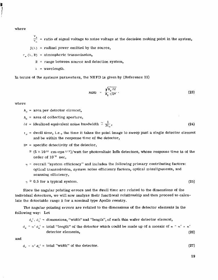
where
vs - = ratio of signal voltage to noise voltage at the decision making point in the system, V"
J ( A ) = radiant power emitted by the source,
T~ ( A , R ) = atmospheric transmission,
R = range between source and detection system,
x = wavelength.
In terms of the systems parameters, the NEFD is given by (Reference 11)
where
A, = area per detector element,
A, = area of collecting aperture, 1
Af = idealized equivalent noise bandwidth 2 K,,
t, = dwell time, i.e., the time it takes the point image to sweep past a single detector element and be within the response time of the detector,
D* = specific detectivity of the detector,
(5 X 1 O 1 O cm-cps lI2)/watt for photovoltaic InSb detectors, whose response time is of the order of sec,
71 = overall "system efficiency" and includes the following primary contributing factors: optical transmission, system noise efficiency factors, optical misalignments, and scanning efficiency,
71 0.5 for a typical system. (25)
Since the angular pointing e r r o r s and the dwell time a r e related to the dimensions of the individual detectors, we will now analyze their functional relationship and then proceed to calculate the detectable range R for a nominal type Apollo reentry.
The angular pointing e r r o r s are related to the dimensions of the detector elements in the following way: Let
d,' , d,' = dimensions, "width" and "length", of each thin wafer detector element,
d, = n ' d,' = total "length" of the detector which could be made up of a mosaic of n = n ' x n '
detector elements, (26)
and
d, = n ' d,' = total "width" of the detector.
19

. .
Then,
A, = d,' d,' = area of each detector element,
and
e;, e�' = instantaneous field of view per detector element in the a and E directions.
Neglecting the finite s ize of the focal spot of the optical system, the angular pointing e r r o r s 6a and S E in the a and E directions a r e
and
where f is the focal length of the system.
As before, the total instantaneous field of view in the a direction 8, is
where Oa was defined earlier as that increment of a over which the system must scan in azimuth during the time that E is completely scanned (from horizon to horizon plus the "dead" o r fly-back time) in order to provide complete coverage (Equations 15 and 19).
In addition, the dwell time td on each detector element is related to the size of each detector element and the scan field in the following manner.
Let us now analyze the iscanand show how it is related to the total scan time ( T s c a n ) for covering the desired search field. Referring to Figure 21 and Equations 19 to 23, but being somewhat more general,
20
I

and
ta = t, for complete coverage, (35)
where
t, = time to scan the instantaneous field of view in the direction B,,
and
t, = time to scan the desired elevation coverage R e ,
therefore
- _ . - e, a
But h is also related to the total time Tscan it takes to scan the necessary azimuth angle na to give the desired search field,
. - 'a a -
T s c a n '
therefore
(37)
I E =0.75= EMISSIVITY
Abrget=12.2 m2 (Apollo C/M blunt face)
I 0 lo00 2000 3000 4000 5000
BODY TEMPERATURE ( O K )
Figure 21-Apollo b l u n t face rad ian t emi t tance i n the wave length reg ion o f i = 3.4p t o 5.3p as a func t i on of body temperature.
One must be very careful in the use of these equations not to substitute the search field Rae for the product R E R,. Because of the way the equations were derived, the RE is the angle through which the elevation angle is scanned. In order to give hemispherical coverage with the type of scanning system being discussed, RE = 360" o r 2 71 radians. Likewise, the a, is the magnitude of the azimuth scan required to give the desired coverage, which is hemispherical coverage in this case. Hence R, = 180" or 71 radians. For hemispherical coverage,
Rc Ra = 2-n' (radians)' (38)
while the search field Rea is 271 steradians for hemispherical coverage. The physical reason why Ran, is greater than Rae in this case may be explained by the fact that there is a considerable amount of redundant coverage at the higher elevation angles with this type of scanning system.
21
61

From Equations 31, 37, and 38,
where Tscan is the total time to scan the hemisphere. This ;scan must not be confused with the i used earlier. The 2 denotes the elevation angular rate of the spacecraft motion relative to the I-R
denotes the elevation angular rate with which the I-R system searches.tracker, while the iscan
Substituting Equations 32 and 41 into Equation 24,
and similarly,
A, = d,' d,' = f 2 Fa F E . (41)
It now becomes clear that when equations 44 and 45 a r e substituted for A, and A f in Equation 23, that the angular e r r o r s will cancel out, and for the system being considered, Equation 23 may be written as
The system's range detection capability may be expressed as
and to a good approximation for a narrow wavelength band,
Substituting Equation 42 into 44 and simplifying the notation, for the system being considered,
22

Thus, the system's maximum range detection capability is independent of the angular pointing e r ro r s but depends in large part on the focal length, the magnitude of the search field, the scan rate or the time it takes to scan this field, the diameter of the energy collecting aperture, and the number of detector elements per ''row" in the mosaic which makes up the total detector. Thus, it can be seen that the number of detector elements per row is the important factor and not the total number of detector elements in the mosaic. Hence, it might be more economical to build only one row of detector elements and let this row rotate about the vertical axis, in which case slip rings would need to be used as discussed earlier.
Sample Calculation-A rigorous computation would require a knowledge of the product J(A) T~ (A , R ) in order to perform the integration of Equation 43;however a close approximation is obtained by replacing the integral with the product of J ( A , -A,) and r a (A1 -A,, R ) , where J ( A , -A,) is the source o r target radiant power in the wavelength region A, to A , and T~ ( h l -A,, R ) is the mean atmospheric transmission in this wavelength region as a function of R. For instance, tabulated below are some cursory values of T ( A , -A,, R ) for the case where R = 600 n.mi. the IRATS is on an aircraft at 35,000 ft , and the heat source (target) is above 100,000 f t* which it would need to be in order for R to be 600 n.mi. line of sight.
Table 1
Atmospheric Transmissivity at R = 600 n.mi. When the I-R Detection System is at 35,000 Ft Altitude and Source is Above 100,000 Ft (Reference 12).
MeanWavelength Difference Atmospheric Transmission
A I - A 2 r a ( A I -4) Remarks 1(microns) (percent) I 1.4 - 2.4
3.25 - 3.5
3.5 - 5
70
-65
-50
Based on experimental data
Computed
Computed
The J ( X ~- x 2 ) is computed as follows. When the source is a diffuse radiator, the observed radiation from a given surface element varies with the cosine of the angle between the line of sight and the normal to the surface element. This is called Lambert's law of cosines (Reference 11). The radiant power dp in watts emitted by the surface dA into the solid angle d.0 = s i n 0 dB d+, where B and @ a re the spherical coordinates, is
where N is the radiance of the source in watts per unit area per unit solid angle, and dJ = N d A in watts per unit solid angle.
*Private Communication, R. A. Stacy, AVCO Corporation, Electro Optical Advanced Technology, Cincinnati, Ohio, September 22, 1964.
23

The heat shield surface element dA is radiating from one side only. Thus integrating over the solid angle to get the radiant power emitted by the surface element dA into the hemisphere gives
Since the radiant emittance of the target in watts per unit a rea is
dP = W '
then W = nN for a Lambertian radiator. (49)
This Equation 49 is equally valid for either the total radiant emittance at all wavelengths or when referred to a particular wavelength, provided only that the surface obey Lambert's law (Reference 11, P. 26). Similarly, the radiant emittance of the target in watts per unit solid angle may be written as
where the integral is taken over the radiating surface (in this case the heat shield on the blunt side of the spacecraft). Equation 50 assumes that the radiance N of the source is a constant over its entire radiating area, which is a simplifying assumption for purposes of computation, in which case
W-J = N * t a r g e t = n A t a r g e t '
where A t a r g e t is the a rea of the heat shield on the blunt side of the reentering spacecraft. It is important to note that it is being assumed here that the infrared detection system is looking at the blunt side of the target, where the temperature is greatest.
From Kirchoff's law of radiation,
(52)
so that
(53)
24

L
... ... . ..... -...- . . . .. ,,-,....., , ,.
where W B A i s shown in Figure 4 as a function of A for temperatures of 1000"K, 1500"K, and 2000°K because it appears likely that this is the temperature range of interest as might be deduced from Figure 3.
Using the trapezoidal rule to numerically integrate the spectral radiant emittance of Figure 4 over the wavelength region of 3 . 4 ~ (about the optimum wavelength region for detection withto 5 . 3 ~ InSb detectors), one obtains the radiant emittance.
which is plotted as a function of temperature in Figure 19, for the Apollo C/M blunt face where E = 0.75 and A t a r g e t _= 12.2.m2.
Some typical Apollo C/M reentry parameters (Altitude, time, range to go, relative velocity, and blunt face temperature at the center) a r e given in Figures 18, 19, 22, and 23* (References 14, 15), for the case L/D = 0.34 and W&A = 67 lbs/ft2.
Assuming that the IRATS uses a row of 20 InSb detector elements each with dimensions I
d,' ,L
1 0 .020 i n . 0 .050 cm , 60,OOOr 6000 1 REENTRY RANGE 600, OOO =25W n. mi.
and L / D = 0.34 50,0001 50001 W = 67.04 Ibs/ft2
500,000 d,' ?' 0.010 i n . 2 0 . 0 2 5 cm , y =-6.05'
a 40,000 I 400,000 h
y. -d v- 50,000 2000 L/ D =0.34
500,000 % v
-a W =67.04 Ibs/ft2
30,000- 300,000 -I
c 40J000-400,000 <
V9 30,000- 300,000 20,000. 200,000
YE 20,000 - 200,000 I-
5 10,OOo. 100, 000
y 10,000- 100, 000
0- .-\. e O L I
01 " I I " - . . --.\. \
0Id0 2& 3& 400 ! 0 200 400 600 800
TIME (secs)
Figure 22-Apollo C/M reentry altitude, range, and Figure 23-Apollo C/M reentry altitude range, and magnitude of relative velocity as a function of time for magnitude of relative velocity as a function of time for a range to go of greater than 1500 n.mi. and a time of a range to go of greater than 3000 n.mi. and a time of 500 secs. 800 secs.
'Strouhal, G. , "Surface Temperature and Mass Loss Information," Manned Spaceflight Center, ES3/Head, Thermal Protection Systems Section, Memorandum, September 17, 1964 (Confidential)..
25

which is well within the state-of-the-art, a focal length of 8 in. as before, D* of about (5 X 10" cm-cps '/')/watt, and a Do of 10 inches which seems a reasonable value for the type of system being considered, it follows that
- % ' ( 8 )- 20 ( . 0 2 0 ) 2 sec
,x, = 200 rad/sec ,
4' .OlO td - * - 8 ( 2 0 0 ) - 6 . 3 x SeC ,
e 'scan
which is compatible with the response time of this In% detector (Reference 11).
With these system parameters, let us now examine the signal to noise ratio, false alarms, and probability of detection as a function of the Apollo C/M body temperature and slant range.
System Parameters
fF = - = 0.8,
DO
Do = 10 in
D* = (5 X 10" cm-cps'/')/watt at 77°K (Reference ll),
n ' = 20 = no. of detectors,
d,' = 0.020 in detector dimensions,
d,' = 0.010 in
and
T ) = 0.5.
For the system being considered, Table 2 lists specific values of NEFD for corresponding values of T s c a n . As stated previously, Tscm represents the total time necessary to scan the search field Rae; and NEFD is an abbreviation for noise equivalent f lux density, as represented by the equation
26

w VI
where NEFD is expressed in watts/n.mi.'. By making use of the equation
where T~ = 0.5 = atmospheric transmissivity, one obtains the results shown in Figures 24, 25, 26, and 27 for the above NEFD's, the expected temperature ranges (Figures 18 and 19) and corresponding radiant emittance ( J ) for the reentering Apollo C/M.
I SYSTEM PARAMETERS
n ' = io NO. OF DETECTORS dd, = 0.020 in d: = 0.010 in } DETECTOR DIMENSIONS
2 10K 1 = 0.5 SYSTEMS OVERALL OPTICAL EFFICIENCY
T,,,,= 2 SEC TO SCAN A HEMISPHERE$ R, R, = 2 H ', BECAUSE OF REDUNDANT5 9 COVERAGE AND "FLYBACK" TIME.
-g 1000
2 g B2 100G ;iZ (3VI
2 10 8 e 5 NEFD=27.Bx 10-3watis/n. mi. '
I1 - I I I I I 0 200 400 6
RANGE (n.mi . )
Figure 24-IRATS signal to noise ratio as a function of detection range and Apollo C/M body temperature for an NEFD of 27.8 x watts/n.mi.'.
Table 2
Corresponding Values of Tscen and NEFD.
NEFD
(watts/n.mi .2)
27.8 10-3
22.7 x 1 0 - ~
19.7 x 10⁻³
16.1 x 10⁻³
looKbSYSTEM PARAMETERS fF = - = O . BDo
D = 10 in D:= ( 5 x lo ' 'cm-cps1/2) / , , t ta t770~ n l = io NO. OF DETECTORS1 dd, = 0.020 in DETECTOR DIMENSIONSd: = 0.010 in
1 = 0.5 SYSTEMS OVERALL OPTICAL 1OK EFFICIENCY
T,,,,= 3 SEC TO SCAN A HEMISPHERE R, R, = 2 n ', BECAUSE OF REDUNDANT
COVERAGE AND "FLYBACK" T M E .
1000
1 10 ° ~
NEFD =22.7X 10⁻³watts/n. mi.2
I I I I I l 0 200 400 t 0
RANGE (n.mi . )
Figure 25-IRATS signal to noise ratio as a function of detection range and Apollo C/M body temperature for an NEFD of 22.7 x watts/n.mi.2.
27

n ’ = 20 =NO. OF DETECTORS
= o.020 i n } DETECTOR DIMENSIONSd: = 0 . 0 1 0 in q = 0.5 SYSTEMS OVERALL OPTICAL
EFFICIENCY T,,,,= 4 SEC TO SCAN A HEMISPHERE
R, R, = 2nZ, BECAUSE OF REDUNDANT COVERAGE AND “FLYBACK “ TIME.
NEFD = 1 9 . 7 X 10⁻³watts /n . mi.’ I 1 I I I I I 1
RANGE ( n . m i . )
Figure 26-lvTS signal to noise ratio as a function of detection range and Apollo C/M body temperature for an NEFD of 1.97 x watts/n.mi.2.
I SYSTEM PARAMETERS
F= -f = 0.8 Do
Do = 10 in D+ = 5 X 1 0 ” c m - c p s -watt -1at 77OK
z n ’ = ZO=NO.OF DETECTORS dd, = 0.020 in } DETECTOR DIMENSIONS5 F, d: = 0 . 0 1 0 i n q = 0.5 SYSTEMS OVERALL OPTICAL
10K EFFICIENCY T,,,, = 6 SEC TO SCAN A HEMISPHERE
R, R, = 2 n ’,BECAUSE OF REDUNDANT COVERAGE AND “FLYBACK“ TIME.
1000
1 0 0
1 0
NEFD = 16.C5x 10-3watts /n . mi.-’
I I I 1 I
RANGE ( n . m i . )
Figure 27-IRATS signal to noise ratio as a function of detection range and Apollo C/M body temperature for an NEFD of 16.05 x watts/n.mi.’.
The probability of detection is a function of both the signal to noise ratio and the log,, (TfaAf n’)
(Reference 11, Figure 13-4)where
Tscan
T f a = -“ f a = mean time between false alarms, . . (55)
and where
n f a = number of false alarms for each scan of the search field (in this case a hemisphere).
As before,
28

. - . . . .
and
R E n a = 2vZ, because of overlapping cov- .-E
erage and dead time ("flyback" time). c v
Hence, for the system being considered,
= 6 . 3 - loglo n f a (57)
n ' = 20 = NO. OF DETECTORS
Using these foregoing results, Figure 28 d: = 0.010 in = o.020 "1 DETECTOR DIMENSIONS
gives the maximum detection range for this n = 0.5 SYSTEMS OVERALL OPTICAL EFFICIENCYsystem as a function of Apollo C/M body tem- T,,,,= 2 SEC TO SCAN A HEMISPHERE
perature and probability of detection for a 3.01 $2, i,,= 2 r 2 , BECAUSE OF REDUNDANT
given allowable false alarm rate (chosen to be COVERAGE AND "FLYBACK " TIME. I I
0.01 and 0.001 false alarms per hemispherical 1000 1100 1200 1 IO scan in Figure 28). Thus, it can be seen that APOLLO BODY C/M TEMPERATURE (OK)
such a system, which is within the present Figure28-IRATS maximum detection range as a function
state-of-the-art, can probably meet the re- of target temperature, probability of detection (P,) and quirements set forth in Reference 1. false alarm rate (n fa ) .
CONCLUSIONS
The problem was analyzed from a mission point of view for using an Infrared Acquisition and Tracking System (IRATS) on board a jet aircraft fo r monitoring the reentry of the Apollo Command Module primarily to determine the aircraft navigational accuracy requirements; and secondarily to determine the IRATS capability to meet the acquisition time, detection range, probability of detection, and pointing accuracy requirements set forth in Reference 1, which a r e repeated here for completeness:
1. Hemispherical coverage with a 99% acquisition probability for:
a. An elevation E 1" to 2O, corresponding to a slant range r = 550 n.mi. using an acquisition time T = 5 sec and an average spacecraft height of 350 k feet.
b. An elevation E = 5" to 6O, corresponding to a slant range r = 350 n.mi. using an acquisition time T = 2-1/2 sec and an average spacecraft height of 350 k feet. (Reference 1, Figures 6, 7, and 8), assuming temperatures between 1000% and 2000% and a heat shield area of 130 feetZ.
29

2. Capable of mounting on K-135 jet aircraft as indicated in Figure 5 Reference 1.
3. Capable of providing maximum angular tracking rates of 15 degrees per second for overhead passes of the spacecraft.
4. Capable of lock-on after initial hemispherical search.
5. Azimuth and elevation angular outputs with angular RMS values *3 mrad to use for rough trajectory determination and antenna pointing.
6. Discrimination capability of 99% of the "real" target.
7. Real time display capability and on board recording for post flight analysis.
First, it was concluded that, in order to be compatible with the other requirements, the aircraft navigational requirements should be about &2n.mi. (lo) on each of the latitude and longitude axes, assuming a negligible altitude error , during the time the IRATS equipped aircraft is tracking the reentry vehicle. That is, the navigation system must provide this accuracy over a period of about 4 hours because the aircraft must leave its land base, fly to its predetermined station location, and wait for the reentry.
Secondly, it appears likely that the above mentioned requirements set forth in Reference 1 a r e within the state-of-the-art of present technology. For instance, using a scan time of 2 sec to scan the hemisphere and the system parameters shown in Figure 28, then the probability of detection could be about 0.995 with a false alarm rate of 10-*/271 steradian at a range of 580 n.mi. and an
Apollo C/M body temperature of 1300°K.
(Manuscript received February 24, 1966)
REFERENCES
1. Vonbun, F. O., "Apollo Reentry Infrared Support," GSFC Document X-513-65-4, December 1964.
2. Plotkin, H. H., "Infrared Reentry Tracking," GSFC Document X-524-62-136, August 10, 1962.
3. Kalil, F., "Infrared Acquisition System," GSFC, Systems Analysis Office Teckiical Brief, November 20, 1964.
4. Kalil, F., "Infrared Acquisition and Tracking System-Preliminary Mission System Specifications," GSFC, Systems Analysis Office Technical Brief, December 8, 1964.
5. Richard, H. L., "Summary Report Apollo Infrared Acquisition and Tracking System," GSFC Document X- 524- 65-290, September 1965.
6. Moore, J. R., "Recommendations for Improved Acquisition System for Aircraft Instrumentation,'' GSFC Document X-513-65-12, December 30, 1964.
30
7. Vonbun, F. O. , "Reentry Tracking for Apollo," GSFC Document X-513-64-85, March 6, 1964.
8. Pierce, J. A., McKenzie, A. A., and Woodward, R. H., "LORAN," New York: McGraw-Hill, 1948.
9. Pierce, J. A., Palmer, W., Watt, A. D., and Woodward, R. H., "OMEGA-A World Wide Navigational System, System Specification and Implementation," Pickard and Burns Electronics, Waltham, Mass., Publication No. 886, Project NO. 347, June 1, 1964.
10. Haas, D. L., "Research and Development of Infrared Track-While-Scan Technique," Technical Documentary Report No. ASD-TDR-63-285, AVCO Corp., Cincinnati, Ohio, May, 1963 (Secret).
11. Jamieson, J. A., McFee, R. H., Plass, G. N., Grube, R. H., and Richards, R. G., "Infrared Physics and Engineering," New York: McGraw-Hill, 1963.
12. Jenkins, F. A., and White, H. E., "Fundamentals of Optics," 2nd ed., New York: McGraw-Hill, 1950.
13. "Feasibility Analysis of Infrared Detection and Tracking of a Lunar Return Vehicle," Report No. AR 1900, ACF Industries, November 19, 1964.
14. Tolin, J. W., Jr., Unclassified Attachments to "Guided Apollo Reentry Trajectories for the Typical Lunar Mission,'' Manned Spaceflight Center, FM/Mission Analysis Branch, Memorandum, File Reference 65-FM5-25, June 10, 1965, (Confidential).
15. Bertin, J. J., and Louden, Anna W., "Apollo Reentry Heating as a Function of Angle of Attack," Manned Spaceflight Center Internal Note No. 64-ET-55, August 14, 1964, (Confidential).
31NASA-Langley, 1966
.._ ,...,,.,.-. ,,.-,. - . . . .

“The aeroiiairtical and space activities o f the United States shall be conducted so as to contribute . . . io the expansion of briman kiiowledge of phenometia in the atmosphere and space. The Administratiou shall provide fo r the widest practicable and appropriaie dissemination of information concerning its actjuities and the resrilts thereof .”
-NATIOPU’AL AND SPACE ACTOF 1958AERONAUTICS
NASA SCIENTIFIC AND TECHNICAL PUBLICATIONS
TECHNICAL REPORTS: Scientific and technical information considered important, complete, and a lasting contribution to existing knowledge.
TECHNICAL NOTES: Information less broad in scope but nevertheless of importance as a contribution to existing knowledge.
TECHNICAL MEMORANDUMS: Information receiving limited distribution because of preliminary data, security classification, or other reasons.
CONTRACTOR REPORTS: Technical information generated in connection with a NASA contract or grant and released under NASA auspices.
TECHNICAL TRANSLATIONS: Information published in a foreign language considered to merit NASA distribution in English.
TECHNICAL REPRINTS: Information derived from NASA activities and initially published in the form of journal articles.
SPECIAL PUBLICATIONS: Information derived from or of value to NASA activities but not necessarily reporting the results .of individual NASA-programmed scientific efforts, Publications include conference proceedings, monographs, data compilations, handbooks, sourcebooks, and special bibliographies.
Details on the availability o f these publications may be obtained from:
SCIENTIFIC AND TECHNICAL INFORMATION DIVISION
NATIONAL AERONAUTICS AND SPACE ADMINISTRATION
Washington, D.C. 20546