naval surface warfare center carderock division - … · naval surface warfare center carderock...
TRANSCRIPT

Naval Surface Warfare Center Carderock Division West Bethesda, MD 20817-5700
Approved for public release; distribution is unlimited.
NSWCCD-65-TR–2004/16A May 2013
Survivability, Structures, and Materials Department
Technical Report
Design Equations and Criteria of Orthotropic Composite Panels by
Brian J. Jones
NS
WC
CD
-65-
TR
–200
4/16
A
Des
ign
Equ
atio
ns a
nd C
riter
ia o
f Ort
hotr
opic
Com
posi
te P
anel
s


IN REPLY REFER TO
DEPARTMENT OF THE NAVY NAVAL SURFACE WARFARE CENTER, CARDEROCK DIVISION
9500 MACARTHUR BOULEVARD WEST BETHESDA MD 20817-5700
9078 Ser 65/13-75 5 Nov 13
From: Commander, Naval Surface Warfare Center, Carderock Division
To: Chief of Naval Research (ONR 331)
Subj: GRAPHITE SANDWICH COMPOSITES FOR NAVAL APPLICATIONS
Ref: (a) Graphite Sandwich Composites for Naval Applications, Task R91390 of the FY03 6.2 Surface Ship Hull, Mechanical and Electrical Technology Program (Program Element 0603123N)
Encl: (1) NSWCCD-65-TR–2004/16A, Design Equations and Criteria of Orthotropic Composite Panels
1. Reference (a) requested the Naval Surface Warfare Center, Carderock Division (NSWCCD) to develop the design equations for orthotropic composite plates for principal use in code development. Enclosure (1) is a revised issuance of the original report describing the design equations and criteria for simply-supported orthotropic plates in the context of the design of composite hull and topside structures. It discusses a description of ship structural loads, structural design criteria, and design equations for solid, sandwich and hat-stiffened panels, as well as girders and frames. The Administrative Information section of the report describes the nature of the revisions.
2. Comments or questions may be referred to Mr. Brian J. Jones, Code 655; telephone (301) 227-4130; e-mail, [email protected].
E. A. RASMUSSEN By direction
Copy to:
COMNAVSEASYSCOM WASHINGTON DC [SEA 05D, SEA 05P4 (Gardner, Nappi, Sieve, Smith)]
CNR ARLINGTON VA [ONR 331 (Hess)]
Defense Technical Information Center 8725 John Kingman Road Suite 0944 Fort Belvoir, VA 22060-6218
NAVSURFWARCEN CARDEROCKDIV BETHESDA MD [Codes 3850 (TIC), 60 (SharePoint), 65, 652 (Hwang, Scott, Taylor), 654 (Wells), 655, 655 (Coffin, Fick, Hart, B. Jones, Noland, Pohlit, Udinski)]


Enclosure (1)
Naval Surface Warfare Center Carderock Division West Bethesda, MD 20817-5700
Approved for public release; distribution is unlimited.
NSWCCD-65-TR–2004/16A May 2013
Survivability, Structures, and Materials Department
Technical Report
Design Equations and Criteria of Orthotropic Composite Panels
by
Brian J. Jones


REPORT DOCUMENTATION PAGE Form Approved
OMB No. 0704-0188 Public reporting burden for this collection of information is estimated to average 1 hour per response, including the time for reviewing instructions, searching existing data sources, gathering and maintaining the data needed, and completing and reviewing this collection of information. Send comments regarding this burden estimate or any other aspect of this collection of information, including suggestions for reducing this burden to Department of Defense, Washington Headquarters Services, Directorate for Information Operations and Reports (0704-0188), 1215 Jefferson Davis Highway, Suite 1204, Arlington, VA 22202-4302. Respondents should be aware that notwithstanding any other provision of law, no person shall be subject to any penalty for failing to comply with a collection of information if it does not display a currently valid OMB control number. PLEASE DO NOT RETURN YOUR FORM TO THE ABOVE ADDRESS.
1. REPORT DATE (DD-MM-YYYY) 1-May-2013
2. REPORT TYPEFinal
3. DATES COVERED (From - To) -
4. TITLE AND SUBTITLE
Design Equations and Criteria of Orthotropic Composite Panels 5a. CONTRACT NUMBER
5b. GRANT NUMBER
5c. PROGRAM ELEMENT NUMBER 0603123N
6. AUTHOR(S)
Brian J. Jones
5d. PROJECT NUMBER
5e. TASK NUMBER R91390 5f. WORK UNIT NUMBER
7. PERFORMING ORGANIZATION NAME(S) AND ADDRESS(ES) AND ADDRESS(ES) 8. PERFORMING ORGANIZATION REPORT
NUMBER NSWCCD-65-TR–2004/16A
Naval Surface Warfare Center Carderock Division 9500 Macarthur Boulevard West Bethesda, MD 20817-5700
9. SPONSORING / MONITORING AGENCY NAME(S) AND ADDRESS(ES) 10. SPONSOR/MONITOR’S ACRONYM(S) Attn ONR 331
Chief of Naval Research One Liberty Center 875 North Randolph Street, Suite 1425 Arlington, VA 22203-1995
11. SPONSOR/MONITOR’S REPORT NUMBER(S)
12. DISTRIBUTION / AVAILABILITY STATEMENT Approved for public release; distribution is unlimited.
13. SUPPLEMENTARY NOTES This report is a revision of NSWCCD-65-TR-2004/16, dated June 2004.
14. ABSTRACT The U.S. Navy is currently pursuing lightweight material options for shipboard structural applications, including hull, topside and mast structures. It is necessary to develop preliminary design criteria and methods to assess structures before the development of detailed finite element models. The design equations and criteria presented in this report are for simply-supported orthotropic plates typically used in composite ship structures. The design equations presented provide orthotropic plate solutions for principal use in code development. In addition, the method could extend to overall ship structural design, for scantling design, or for input into an overall design program. This document provides design equations and criteria for simply-supported orthotropic plates in the context of the design of composite hull and topside structures. It identifies ship structural loads, structural design criteria, and design equations for solid, sandwich and hat-stiffened panels, as well as girders and frames.
15. SUBJECT TERMS ship structures, composite materials
16. SECURITY CLASSIFICATION OF: 17. LIMITATION OF ABSTRACT
SAR
18. NUMBER OF PAGES
47
19a. NAME OF RESPONSIBLE PERSONMr. Brian J. Jones
a. REPORT UNCLASSIFIED
b. ABSTRACT UNCLASSIFIED
c. THIS PAGEUNCLASSIFIED
19b. TELEPHONE NUMBER (include area code) (301)-227-4130
i/ii
Standard Form 298 (Rev. 8-98)Prescribed by ANSI Std. Z39.18


NSWCCD-65-TR–2004/16A
Contents
Page
iii
Figures............................................................................................................................................ iv
Tables ............................................................................................................................................. iv
Administrative Information .............................................................................................................v
1. Introduction .................................................................................................................................1
2. Ship Structural Design Loads .....................................................................................................1
3. Composite Failure Modes ...........................................................................................................4 The Definition of Failure ........................................................................................................4
Damage ..........................................................................................................................4 Collapse..........................................................................................................................4
4. Overall Ship Design Process .......................................................................................................5 4.1. Ship Cross-Section Analysis ...........................................................................................5 4.2. Composite Panel Analysis ..............................................................................................6
5. Design Criteria (Limit States) .....................................................................................................6 5.1 Deflection Requirements ..................................................................................................6 5.2 Strength Limits .................................................................................................................7 5.3 Buckling Criteria...............................................................................................................7 5.4 Natural Frequency Criteria ...............................................................................................7 5.5 Design Allowables and Factors of Safety .........................................................................8
5.5.1 Traditional Factor of Safety Approach .................................................................8 5.5.2 Design Allowable Method ....................................................................................8
6. Panel Design Equations ..............................................................................................................9 6.1 Solid Laminate Panel Design ............................................................................................9
6.1.1 Deflection of Solid Laminate Panel ......................................................................9 6.1.2 Stress of Solid Laminate Panel ...........................................................................11 6.1.3 Buckling of Solid Laminate Panel ......................................................................12 6.1.4 Natural Frequency of Solid Laminate Panel .......................................................15 6.1.5 Design Criteria for Solid Laminate Panel ...........................................................15
6.2. Sandwich Panel Design ................................................................................................17 6.2.1 Deflection of Sandwich Laminate Panel .............................................................17 6.2.2 Stress of Sandwich Laminate Panel ....................................................................20 6.2.3 Buckling of Sandwich Laminate Panel ...............................................................22 6.2.4 Natural Frequency of Sandwich Laminate Panel ................................................23 6.2.5 Design Criteria for Sandwich Laminate Panel ....................................................24
6.3. Hat-Stiffened Panel Design ..........................................................................................25 6.3.1 Stiffener or Girder/Frame Design .......................................................................25 6.3.2 Overall Stiffened Panel Design ...........................................................................29
NSWCCD-65-TR–2004/16A
Contents
Page
iv
6.3.3 Design Criteria for Hat-Stiffened Panels ............................................................32
References ......................................................................................................................................33
Appendix A Classical Laminate Theory (CLT): ....................................................................... A–1
Appendix B Sample Area and Moment of Inertia Calculation ................................................... B–1
Figures
Page
Figure 1. Categories of Ship Structural Loads ................................................................................2 Figure 2. Generalized Rectangular Plate with Typical Panel Loads ............................................10 Figure 3. Sandwich Panel Dimensions .........................................................................................17 Figure 4. Hat-Stiffened Panel Dimensions ...................................................................................25 Figure 5. Hat-Stiffener Dimensions .............................................................................................26 Figure 6. General Shear and Moments .........................................................................................28 Figure 7. Interframe Buckling Modes ...........................................................................................31 Figure 8. Extraframe Buckling Modes..........................................................................................31
Tables
Page
Table 1. Ship Structures Load Application Chart ...........................................................................3

NSWCCD-65-TR–2004/16A
v
Administrative Information
The Structures and Composites Division (Code 65) of the Survivability, Structures and Materials Department at the Naval Surface Warfare Center, Carderock Division (NSWCCD), performed the work described in this report. The work was funded by the Office of Naval Research, Code 334 as part of the R91390 Task of the FY03 6.2 Surface Ship Hull, Mechanical and Electrical Technology Program (Program Element 0603123N).
The original issuance of this report was published in June 2004 as a compilation of design criteria for Navy composite structures and design equations for composite plates (laminate and sandwich) and stiffeners. Many of these equations tend to be the complete or generalized solutions that require a computer to solve the complex summations. NSWCCD developed a computer program to design composite panels using these equations. During the development of this computer program minor errors were found in certain equations. This revision addresses the changes made to the original document. Corrected information is identified with a bar in the left margin.
As design and analysis of composites continues to evolve, undoubtedly these equations will be used and the corrected forms will eliminate potential errors during the design process. No further changes are recommended at this time.

NSWCCD-65-TR–2004/16A
vi
This page intentionally left blank.

NSWCCD-65-TR–2004/16A
1
1. Introduction
The U.S. Navy is currently pursuing lightweight material options for shipboard structural applications, including hull, topside and mast structures. It is necessary to develop preliminary design criteria and methods to assess structures before the development of detailed finite element models.
The design equations and criteria presented in this report are for simply-supported orthotropic plates typically used in composite ship structures. The design equations presented provide orthotropic plate solutions for principal use in code development. In addition, the method could extend to overall ship structural design, for scantling design, or for input into an overall design program.
This document provides design equations and criteria for simply-supported orthotropic plates in the context of the design of composite hull and topside structures. It identifies ship structural loads, structural design criteria, and design equations for solid, sandwich and hat-stiffened panels, as well as girders and frames.
2. Ship Structural Design Loads
Loads on the hull structure define the basic requirements for any ship structure. The hull loads are related to geometry, size, speed, and operational and combat environments of the ship. The determination of the loads is a crucial part of the composite structural design process.
Within the ship structure, there are a variety of loads which are experienced by the various parts. Because of the variety of loads acting on the hull, bulkheads and decks, it is important to first identify, then define each load and conditions in which they can occur. Only when there is an understanding of the frequency can we understand when and how the loads may be combined.
From the structural design manual for surface ships [Reference 1], loads are grouped into four categories, basic loads, sea environment, operational environment, and combat environment; see Figure 1. Table 1 shows ship structural members and pertinent loads and their combination for analysis.

NSWCCD-65-TR–2004/16A
2
Loads for naval ship design are discussed in the structural design manual for surface ships [Reference 1] and also by, a topside design guide [Reference 2]. These documents provide much of the background information on which this report is based. Recently, classification societies, Det Norske Veratis (DNV) and American Bureau of Shipping (ABS), have added more specific information about basic, sea environment, and operational environment loads of naval ships and of ships with non-traditional hull forms [References 3, 4, 5].
SHIP STRUCTURAL LOADS
BASIC LOADS
SEA ENVIRONMENT
OPERATIONALENVIRONMENT
COMBATENVIRONMENT
STANDARDLIVE LOADS
DEAD LOADS
LIQUIDS/TANKSLOADS
LOADS BASED ON KNOWN EQUIPMENT AND CARGO
HULL GIRDERLOADS
SEA LOADS
WEATHERLOADS
SHIP MOTION LOADS
SLAMMINGLOADS
FLOODING
AIRCRAFT/HELOLANDING
TANK OVERFILL
DOCKING
UNREP OP’s
MORE …
SHOCK
AIRBLAST
FRAGMENTS
GUN BLAST& REACTION
MISSILE BLAST AND ACCIDENTALIGNITION
LOADS TO COMBINED INDIVIDUAL LOADS
Figure 1. Categories of Ship Structural Loads

NSWCCD-65-TR–2004/16A
3
Table 1. Ship Structures Load Application Chart
Ship Component
Loads to be Combined Load to be Applied Independently
Prim
ary
Hydrostatic
Tank Loads
Dead Loads
Live Load
Weather
Stow
age
Wave S
lap
Tank O
verflow
Flooding
Gun and M
issile Blast
Interior Pressure
Dry-D
ocking
Operating
Aircraft/H
elo Landing
Nuclear A
ir Blast
Shock
1 Shell & Frame A Midship X X X X - - - - X - - - X X - X - B Forward X X X X - - - X X - - - X X - X -
C Aft X X X X - - - - X - - - X X - X - D Sponson Shell - X - X - X - X - - - - - X - X - E Web Frame - X X X - X X X X X X - X X - X -
2 Bulkhead A Longitudinal X - X X - - - - X X - X - - - - - B Transverse - - X X - - - - X X - X - - - X - C Bends - - - X X - X - - - - - - - X X -
D Misc. - - X X - - - - X X - X - - - - -
3 Decks A Interior X - X X X - X - X X - X - X - - -
B Weather X X - X X X X X X - X X - X X X - C Platforms - - X X X - X - X X - X - - - - -
4 Stanchion - X X X X X X - X X X X - X X X -
5 Superstructures A Long X X - X X X X - - - X X - X X X - B Short - X - X X X X - - - X X - X - X -
C Deckhouse - X - X X X X - - - X X - X - X -
6 Foundations A Critical Machinery/Equipment - - - X - - - - - - - - X - - X
B Secondary Machinery/Equipment
- - - X - - - - - - - - X - - -
C Exposed Locations - - - X X - X - - X - - X - X -
NSWCCD-65-TR–2004/16A
4
3. Composite Failure Modes
The Definition of Failure
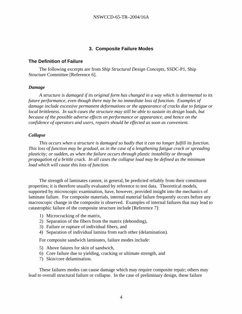
The following excerpts are from Ship Structural Design Concepts, SSDC-P1, Ship Structure Committee [Reference 6].
Damage
A structure is damaged if its original form has changed in a way which is detrimental to its future performance, even though there may be no immediate loss of function. Examples of damage include excessive permanent deformations or the appearance of cracks due to fatigue or local brittleness. In such cases the structure may still be able to sustain its design loads, but because of the possible adverse effects on performance or appearance, and hence on the confidence of operators and users, repairs should be effected as soon as convenient.
Collapse
This occurs when a structure is damaged so badly that it can no longer fulfill its function. This loss of function may be gradual, as in the case of a lengthening fatigue crack or spreading plasticity; or sudden, as when the failure occurs through plastic instability or through propagation of a brittle crack. In all cases the collapse load may be defined as the minimum load which will cause this loss of function.
The strength of laminates cannot, in general, be predicted reliably from their constituent properties; it is therefore usually evaluated by reference to test data. Theoretical models, supported by microscopic examination, have, however, provided insight into the mechanics of laminate failure. For composite materials, internal material failure frequently occurs before any macroscopic change in the composite is observed. Examples of internal failures that may lead to catastrophic failure of the composite structure include [Reference 7]:
1) Microcracking of the matrix, 2) Separation of the fibers from the matrix (debonding), 3) Failure or rupture of individual fibers, and 4) Separation of individual lamina from each other (delamination).
For composite sandwich laminates, failure modes include:
5) Above faiures for skin of sandwich, 6) Core failure due to yielding, cracking or ultimate strength, and 7) Skin/core delamination.
These failures modes can cause damage which may require composite repair; others may
lead to overall structural failure or collapse. In the case of preliminary design, these failure

NSWCCD-65-TR–2004/16A
5
modes can affect structural design criteria. Four classes of design criteria must be met for a feasible design:
Deflection requirement,
Strength limits,
Buckling, and
Natural frequency.
Properties normally required for design purposes and failure evaluation/prediction are tensile, compressive, flexural, in-plane and interlaminar shear strengths. Material modulus data are needed to determine deflection, buckling strength and natural frequencies. Material strength data are needed for comparison with strength allowables.
4. Overall Ship Design Process
The structural design process is initiated by assuming a set of ship hull cross-sectional scantlings for the midship plating. For the first cycle of the design, the contributions of longitudinal stiffeners to the overall hull sectional modulus may be neglected. Using the longitudinal hull girder loads, the induced primary stresses in the deck and hull bottom are calculated [References 8, 9, 10, 11, 12]. With these primary in-plane stresses and assumed transverse frame spacing and plate thickness, the assumed scantlings are checked for buckling under in-plane loads and ultimate strength under combined in-plane and lateral loadings. The calculated stress results and design criteria are used to modify the assumed set of cross-sectional scantlings and the iterative processes continues until an optimum set of scantlings is obtained.
4.1. Ship Cross-Section Analysis
Hull girder analysis requires that deck and bottom stress and overall ship deflection is checked. Using a maximum bending at mid-ship, the induced stress in the deck and bottom is given by:
),min(:...
...
TensionnCompressioult
ultBKeel
ultDDeck
whereSOFI
McSOFI
Mc
In addition to stress, hull girder deflection must be checked. Assume that the ship’s weight is evenly distributed between perpendiculars and that the moment of inertia throughout the length of the hull is equal to the value at midships. The evenly distributed weight required to give a bending moment for the case of simply-supported ends gives [Reference 13]:

NSWCCD-65-TR–2004/16A
6
PL
MW
8
The beam deflection can be calculated from the following:
200/1384
5 3
EI
WLP
The hull girder deflection is required to be less than 1/200.
4.2. Composite Panel Analysis
From the ship cross-sectional analysis mentioned above, in-plane axial forces and in-plane bending moments are determined. With knowledge of the out-of-plane load requirements, the ship structure can be segmented into panels for design analysis. Necessary equations and design criteria will be discussed in subsequent sections.
The design equations are split into three categories: solid laminate panels, sandwich panels, hat-stiffened-panels. Four classes of design criteria must be met for a feasible design:
Deflection requirement, Strength limits, Buckling, and Natural frequency.
5. Design Criteria (Limit States)
5.1 Deflection Requirements
Structural stiffness is a major driver in the design of composite structures due to the low composite modulus. Deflection limits can be absolute limits or limits due to imposed design criteria. Absolute limits represent physical constraints based on tolerances or interference with adjacent structures or equipment. Limits due to design criteria aid in avoidance of other requirements such as crew habitability/visibility, motions (velocity or acceleration) or natural frequency.
The absolute deflection limits must be set on a case-by-case basis and are typically not load case dependent. Specified design criteria limits have values which could be as much as 1/25 and as little as 1/1000 in some civil engineering applications [Reference 14].

NSWCCD-65-TR–2004/16A
7
Deflection limits used in the past for composite structural design are:
L/200 internal (walking) decks panels L/200 internal (walking) decks frame L/100 internal (non-walking) decks panelsL/100 internal (non-walking) decks framesL/200 hull exterior frames L/150 hull exterior deck panels L/150 hull exterior panels (elsewhere) L/100 topside exterior panels and frame L/50 bulkhead to bulkhead panels
5.2 Strength Limits
Using current methodology, material strengths are determined via stress. Historically, material knockdown factors that reduce ultimate strength values to account for laminate service conditions have also been derived from stress-based testing and calculation.
To determine failure with analytical or numerical (FE) results, maximum stress theory is most-commonly used. In comparison with other failure theories, maximum stress theory is conservative and well understood. Jenkins [Reference 15] stated that failure occurs when one or all of the orthotropic stress values exceed their maximum limits as obtained in uni-axial tension, compression or pure shear stress test, when material is tested to failure. For plane stress, this is:
11 = X 22 = Y 12 = S
5.3 Buckling Criteria
Ship structures generally have: [Reference 16]
Plate Buckling-Critical Member 4Plate Buckling-Non-Critical Member 2Stanchion and Stiffener Buckling 4
5.4 Natural Frequency Criteria
From the DDX deckhouse program, the approach to account for vibration at preliminary design level is to determine the panel’s natural frequency. The local response of individual panels (panel natural frequencies) will be above 125% of the ship’s blade rate values [Reference 17].
Where: Shaft Rate (Hz) = Shaft RPM / 60
Blade Rate (Hz) = # of Blades × Shaft RPM / 60

NSWCCD-65-TR–2004/16A
8
5.5 Design Allowables and Factors of Safety
5.5.1 Traditional Factor of Safety Approach
Typically, a traditional single factor of safety design has been used. Design data sheets for hull structures have used a single factor of safety from the ultimate strength [Reference 18].
stiffener or stanchion 4 static loading 4 long-term loading (creep) 4 fatigue 6 air blast load (one-time-load) 1.25repeated impact load 8
5.5.2 Design Allowable Method
Design allowable stress levels should account for all applicable fabrication and loading condition uncertainties. These uncertainties include, but are not limited to the following:
1. End-use/In-service environment, 2. Fatigue loadings, 3. Sustained loadings, 4. Impact loadings, 5. Form and shape factors, 6. Laminate thickness effects, 7. Manufacturing variables, 8. Residual stresses and strains, and 9. Corrosion effects.
When accounting for these effects by testing or other methods, one may establish design allowables by first determining material allowables, and then applying a reduced factor of safety. The material allowables account for the anticipated in-service, worst-case environmental conditions, for example, elevated temperature, moisture, processing variability (B-basis statistical determinations). When material allowables are known, then the design allowables are determined as follows:
Using the material knockdown factors combined with a load uncertainty, the factor of safety can be determined.
factorsy uncertaint load
factorsknockdown material
F.S.
1
1
φ
K
K j
M
j
i
N
i

NSWCCD-65-TR–2004/16A
9
6. Panel Design Equations
6.1 Solid Laminate Panel Design
Consider a rectangular plate of length, a, width, b, and thickness, t shown in Figure 2. For marine construction, the rectangular panel loads can be simplified into an average edge force Nx, or Ny combined with an in-plane bending moment and in-plane shear, Nxy. In addition, the panel may be subjected to a uniform pressure, P, on the entire panel. Using classical plate theory for thin plates, Z-stress = 0 (no transverse shear deformation), the governing equation for displacement, w, of the plate in the Z direction is
yxFy
wD
yx
wDD
x
wD ,22
4
4
2222
4
66124
4
11
where Dij’s are the flexural rigidities of the plate given by:
12,
112112,
112
312
662112
3121
122112
32
222112
31
11
tGD
tED
tED
tED
With these terms, the governing equation can be rewritten as:
yxFy
w
yx
w
x
w,2
4
4
22
42
1
4
4
where:
2211
6612
11
22 2 ,
DD
DD
D
D
The non-dimensional adjusted plate aspect ratio is given by:
b
aR
4/1
Plate equations are valid for symmetric laminates (with no bending twist coupling, Bij = 0). For further discussion on plate equations, go to the detailed progression in Reference [Reference 19]. Additionally, in laminated parts, the flexural rigidities, Dij’s, can be determined through classical laminate theory see Appendix A.
6.1.1 Deflection of Solid Laminate Panel
The deflection of a composite panel is important in composite design due to the low modulus of laminates. Because the modulus ranges from 1 to 10 Msi, deflection limits can

NSWCCD-65-TR–2004/16A
10
govern design. For a simply-support panel, the deflection solution for a uniform pressure is given by the Navier solution [Reference 20]. This solution converges rapidly for deflection within 20 to 40 terms of the summation.
X
Y
Z
b
a
X
Y
Z
Nxy
Nx(y)=Nxavg+Mx In-plane
Ny(x)=Ny avg+My In-plane
P
Figure 2. Generalized Rectangular Plate with Typical Panel Loads
4
22
2
6612
4
11
...5,3,1 ...5,3,16
)2(2
:
sinsin116
,
b
nD
ab
mnDD
a
mDD
where
b
yn
a
xm
Dmn
Pyx
n mss
For most panels in marine construction, the simply-support deflection is overly conservative. For this reason, the clamped-clamped rectangular panel is calculated [Reference 19]. The maximum deflection of a clamped-clamped rectangular panel is:
if –1 < < (3.5)^0.5
RR
RRRR
D
Pbclamped
1221
212
211
11
4
sinhsinh2
cos2
sinh22
sin2
cosh21
384
5.36,5.36 21
if > (3.5)0.5
2cosh
2sinh
2cosh
2sinh
2sinh
2sinh
1384 2121
22
11
11
4
21
RRRR
RR
D
Pbclamped

NSWCCD-65-TR–2004/16A
11
5.332,5.332 22
21
As an alternative to the piece-wise solution proposed by Roberts & Bao [Reference 19], a continuous function is presented by Lekhnitskii [Reference 21] and similarly by Whitney [Reference 22].
Pa4
D11 0.571 D12 2D66 R2 D22R4
Not only is the continuous function easier to employ computationally, but solution accuracy appears improved over a larger range of aspect ratios and panel material orthotropy.
The maximum deflection of the simply-supported and clamped-clamped panel are combined using a weighted average W to estimated the panel deflection. W ranges between 0 and 1 and is typically taken to be 0.75.
CRCR Y
nCompressioY
X
nCompressioX
Clampedss
N
N
N
N
WW
11
1
6.1.2 Stress of Solid Laminate Panel
For preliminary design and assessment, stresses in the simply-supported rectangular panel offer a conservative estimate of stress in the panel. Stress components can be determined through the extension of the Navier solution [Reference 20]. The Navier solution for a rectangular panel with a uniform pressure gives the following moment and shear resultants due to bending:
...5,3,1 ...5,3,1
2
12
2
114sinsin
116,
n mx b
yn
a
xm
b
nD
a
mD
Dmn
PyxM
...5,3,1 ...5,3,1
2
22
2
124sinsin
116,
n my b
yn
a
xm
b
nD
a
mD
Dmn
PyxM
...5,3,1 ...5,3,1
664
coscos32
,n m
xy b
yn
a
xm
b
n
a
m
Dmn
DPyxM
...5,3,1 ...5,3,1
2
6612
3
112sincos2
116,
n mx b
yn
a
xm
b
n
a
mDD
a
mD
Dmn
PyxQ

NSWCCD-65-TR–2004/16A
12
...5,3,1 ...5,3,1
2
6612
3
222cossin2
116,
n my b
yn
a
xm
b
n
a
mDD
b
nD
Dmn
PyxQ
The maximum stresses for a solid laminate panel are:
t
aQt
bQt
Mt
baM
t
baM
yBendingyz
xBendingxz
xyBendingxy
yBendingY
xBendingX
2
0,2/32
2/,03
0,06
2,
26
2,
26
2
2
2
In addition to the bending stress due to out-of-plane pressure, membrane components can be determined from in-plane loading.
t
Nt
Nt
N
xyMembranexy
YMembraney
XMembranex
6.1.3 Buckling of Solid Laminate Panel
Solid laminate panel buckling can arise from any loads shown in Figure 2. Here we will show the solutions for a simply-support panel under Nx, Ny, Nxy and in-plane bending moments. There is little information on resulting buckling due to combined loaded cases. However, it should be noted that all components of the loads are typically not substantial at the same time. These equations will form the basis for an interaction equation to be used to assess combinations of loading.
In-plane buckling of a simply supported panel due to a uniform edge load for both the X-face and Y-face are given below [Reference 19].

NSWCCD-65-TR–2004/16A
13
X-Edge Load:
b
aD
D
R
where
R
m
m
R
b
DDN
x
x
xXcr
4/1
11
22
2
2
2
2
22211
2
:
2
Y-Edge Load:
a
bD
D
R
where
R
m
m
R
a
DDN
y
y
yYcr
4/1
22
11
2
2
2
2
22211
2
:
2
The panel will buckle in m half waves if
1,11 mmmRmm i
The critical in-plane bending moment along each edge of a simply-supported panel is given by [Reference 23]:
X-Moment
816
2
:
047.0
2
2
2
2
2
2
2
2
222
22112
x
xx
x
xx
xxplaneIn
X
R
k
k
R
R
k
k
R
where
bb
DDM
Cr

NSWCCD-65-TR–2004/16A
14
Y-Moment
816
2
:
047.0
2
2
2
2
2
2
2
2
222
22112
y
yy
y
yy
yyplaneIn
Y
R
k
k
R
R
k
k
R
where
aa
DDM
Cr
the panel buckles in k m-half waves when:
8741.33.1637 5
1637.32.4513 4
4513.21.7346 3
7346.11 2
10 1
i
i
i
i
i
Rifk
Rifk
Rifk
Rifk
Rifk
if Ri is greater than 3.8741, these critical in-plane bending moment can be estimated by:
25.124.18
25.124.18
2
2
2
22112
2
2
2
22112
a
a
DDM
b
b
DDM
planeIny
planeInx
Cr
Cr
For in-plane shear, there are limited solutions for rectangular plate buckling. Here the plate is assumed to be infinitely long, for which Rx approaches infinity. The critical in-plane shear for this case is given by [Reference 23]:
22
4/132211
2
4/132211
938.0532.07.11
4
1
05.5125.84
1
b
DDN
fib
DDN
if
cr
cr
xy
xy

NSWCCD-65-TR–2004/16A
15
6.1.4 Natural Frequency of Solid Laminate Panel
In addition to deflection concerns, the low modulus of composites can make the natural frequency of the panel a concern. The general form of the panel natural frequency is given [Reference 22]:
43
422
22
26612
41112
221
RDRDDDa
where:
= rotational inertia (slugs/in2)
for a simply support panel the fundamental natural frequency is given by the following constants
3
42
1
for a clamped-clamped panel, the fundamental natural frequency is given by the following constants
730.4
3.151
730.4
3
2
1
The true natural frequency can be estimated by a weighting function given by following:
Clampedss WW 1
Typically W is taken to be 0.25.
6.1.5 Design Criteria for Solid Laminate Panel
The following 11 criteria, arising from the above equations, must be satisfied.

NSWCCD-65-TR–2004/16A
16
Stress-X Tensile Laminate ..
.4
Stress-X eCompressiv Laminate ..
1
.3
b Width,respect to with Criteria Deflection Panel 1.2
a Length, respect to with Criteria Deflection Panel 1.1
SF
S
SF
S
N
N
bd
ad
XTTxB
TxM
XC
X
X
CxBC
xM
LIMIT
LIMIT
Cr
LimitFrequency Natural 1.11
nInteractio Buckling ...
1.10
Y Stress,Shear Thickness-Through Laminate ..
.9
X Stress,Shear Thickness-Through Laminate ..
.8
StressShear plane-In Laminate ..
.7
Stress-Y Tensile Laminate ..
.6
Stress-Y eCompressiv Laminate ..
1
.5
222
LIMIT
PlaneInY
PlaneInY
PlaneInX
PlaneInX
XY
XY
Y
Y
X
X
YZyz
XZxz
XYxyBxyM
YTTyB
TyM
YC
Y
Y
CyBC
yM
BSFM
M
M
M
N
N
N
N
N
N
SF
SSF
SSF
SSF
S
SF
S
N
N
CRCRCrCrCr
Cr
where:
dLIMIT = deflection limit for the panel
Si = stress allowable for each component of stress
F.S. = Factor of safety for stress
F.S.B. = Factor of safety for buckling
LIMIT = minimum natural frequency of the panel

NSWCCD-65-TR–2004/16A
17
6.2. Sandwich Panel Design
The design of sandwich panels in this discussion is limited to equal face sheet thickness and similar material (see Figure 3), where Dij’s are flexural rigidities of the plate given by [Reference 24]:
tf
c or hc
d
h
Figure 3. Sandwich Panel Dimensions
3
12
12
3
2112
312
66
3
2
2
21
21
2112
2112
3
2112
3121
12
3
2
2
2112
2112
3
2112
32
22
3
1
1
2112
2112
3
2112
31
11
1112
,1
11
112
,1
11
112
,1
11
112
h
c
G
G
h
chGD
h
c
E
E
v
v
h
chED
h
c
E
E
h
chED
h
c
E
E
h
chED
F
C
FF
F
F
C
F
C
CC
FF
FF
FF
F
C
CC
FF
FF
F
F
C
CC
FF
FF
F
Additional terms are needed to represent transverse shear stiffness of the sandwich laminate. These terms are given by:
c
chGA
c
chGA
C
C
4
42
2344
213
55
6.2.1 Deflection of Sandwich Laminate Panel
Due to transverse shear deformation of the core, a sandwich panel will deflect more than estimated by the classical plate theory. The revised Navier solution for a simply-supported sandwich panel is given by Dobyns [Reference 25]. This solution is general and can apply to sandwich or solid laminate plates where:

NSWCCD-65-TR–2004/16A
18
1 1
1 1
1 1
1 1
sinsin),(
:)(
cossin
sincos
:
sinsin),(
:
m n
m nmn
m nmn
m n
b
yn
a
xmqyxp
dGeneralizeLoad
b
yn
a
xmB
b
yn
a
xmA
Rotations
b
yn
a
xmCyx
ntDisplaceme
mn
mnn
where:
nmmn
pqmn cos1cos1
42
Amn, Bmn, and Cmn can be determined by substitutions into the governing equations resulting in the following solution:
mnmn
mn
mn
qC
B
A
LLL
LLL
LLL
0
0
332313
232212
131211
where:
12/2
244
25533
4423
442
662
2222
5513
661212
552
662
1111
b
na
m
AAL
AL
ADDL
AL
DDL
ADDL
n
m
nm
n
mn
m
nm
nm

NSWCCD-65-TR–2004/16A
19
The Amn, Bmn, and Cmn can be solved:
)det(
)det(
)det(
12122211
23111312
13222312
L
qLLLLC
L
qLLLLB
L
qLLLLA
mnmn
mnmn
mnmn
As in the solid panel case, the simply-support solution is overly conservative. For this reason, the clamped-clamped rectangular panel is calculated from the work by Roberts [Reference 24].
The maximum deflection of a clamped-clamped rectangular panel is:
FF
FF
F
F
CC
FF
FF
clamped
b
EEctF
b
a
E
Es
DD
DD
ssR
b
aGGH
H
FR
where
Rc
t
c
hb
a
EEc
Pb
21122
22112
4/1
22
11
2211
66122
2
2
1323
3
2
42211
3
21124
1
2
2 ,2
33
:
21
1112
These terms are combined using a weighted average, W, to estimate the true panel deflection. The weighting function, W, ranges between 0 and 1. Typically W is taken to be 0.25.
CRCR Y
nCompressioY
X
nCompressioX
Clampedss
N
N
N
N
WW
11
1

NSWCCD-65-TR–2004/16A
20
6.2.2 Stress of Sandwich Laminate Panel
For panel stresses the Navier Solution for a simply-supported panel under uniform pressure with transverse shear deformation was used to determine Mx, My, Mxy. In addition, the shear resultants can be found. This is important because in a sandwich panel the core (only) is assumed to resist shear. Using the solutions for displacement and rotations, the stress couples, Mx, My, and Mxy and shear resultants Qx and Qy can be determined.
1 16666
1 12212
1 122
1 112
2212
1 11211
1 112
1 111
1211
coscos2
12
sinsin
sinsinsinsin
sinsin
sinsinsinsin
m nmnmnxy
m nmnmny
m nmn
m nmny
y
m nmnmnx
m nmn
m nmnx
x
b
yn
a
xm
a
mB
b
nAD
xyDM
b
yn
a
xm
b
nBD
a
mADM
b
yn
a
xm
b
nBD
b
yn
a
xm
a
mADM
yD
xDM
b
yn
a
xm
b
nBD
a
mADM
b
yn
a
xm
b
nBD
b
yn
a
xm
a
mADM
yD
xDM
b
yn
a
xm
a
mCAA
x
wAQ
m nmnmnx
sincos1 1
5555
b
yn
a
xm
b
nCBA
y
wAQ
m nmnmny
cossin1 1
4444

NSWCCD-65-TR–2004/16A
21
The resulting stresses in the face sheet and core shear are:
f
yCoreyz
xCorexz
f
xyBendingxy
f
yBendingY
f
xBendingX
tcdd
aQd
bQ
dt
M
dt
baM
dt
baM
:where
0,2/
2/,0
0,0
2,
2
2,
2
In addition to the bending stress due to out-of-plane pressure, membrane components can be determined from in-plane loading.
f
xyMembranexy
f
YMembraney
f
XMembranex
t
N
t
N
t
N
2
2
2

NSWCCD-65-TR–2004/16A
22
6.2.3 Buckling of Sandwich Laminate Panel
There are several modes of buckling for a solid-core sandwich panel. These modes include face-wrinkling instability, core shear instability, or overall buckling. The critical stress for buckling is discussed by Vinson [Reference 26] and given below. Overall buckling is given by:
1 ,,1,
panel supported-simply afor
,
,2,,
2
:
1
2
for 14
2
12
2
322
2
41
23
2211
2
2
13
2211
2
2
23
1312132
2211
123
11
221
1
3221123
22231
423
1
3
42311
41
32211
112
2
22112112
2..
ka
bCC
b
aCC
D
DD
bV
D
DD
bV
G
GrBBB
DD
DB
D
DB
B
CCBCBCBCBCCA
where
C
AVVVCB
B
C
C
VCBCB
VC
VA
B
CCBCB
K
rBkVKb
hEE
tN
yx
C
CF
yxx
y
xy
xcFF
FF
fBOX CR
When the condition for overall buckling is satisfied, the panel may still buckle due to core shear instability given by:
f
cC
SCX t
hGCR 2
13..
Other modes of core shear crimping or instability are given by:
f
cC
SCY t
hGCR 2
23..
f
cCC
SCXY t
hGGCR 2
2313..

NSWCCD-65-TR–2004/16A
23
Face wrinkling instability causes a short-wave buckling of the sandwich skins, primarily when core modulus is low or skins are thin. The critical in-plane edge load to cause face wrinkling is estimated by two methods. The first by Vinson [Reference 26]:
2/1
2112
221131..
13
2
FF
FFC
c
fWFX
EEE
h
tCR
A second estimate of critical in-plane edge load to cause face wrinkling is given by Hoff and Mautner [Reference 27]:
5.0
3/1
133112..
cwhere
GEEc CCFWFXCR
Buckling will occur at the minimum edge load as calculated above. For the assessment of buckling in the Y direction, terms can be rearranged with proper directionality. To assess shear face wrinkling, stress is given by the lower of the following [Reference 7]:
FFFF
F
CCFWF
XY
CCFWF
XY
EEGEE
cwhere
GEEc
GEEc
CR
CR
2211
12
1211
45
3/1
23345.
3/1
13345.
4
1
24
1
4
1
44.0
3
3
The in-plane moment and shear critical loads equations can be used with proper flexural rigidities for the sandwich panel.
6.2.4 Natural Frequency of Sandwich Laminate Panel
Additionally, the natural frequency of the sandwich panel can be approximated with equations used in Section 6.1.4 with proper flexural rigidities for the sandwich panel. Note in this case, transverse shear deformation consideration is not used.

NSWCCD-65-TR–2004/16A
24
6.2.5 Design Criteria for Sandwich Laminate Panel
The 14 design constraints which must be satisfied for a feasible design are shown below. Note that core shear stresses become a critical component in the design.
LimitFrequency Natural 1.14
nInteractio WrinklingFace Buckling, Local ....
1.13
nInteractio InstabiltyShear Core Buckling, Local ....
1.12
nInteractio Buckling Global ...
1.11
direction- ZStress, eCompressiv Core ..
.10
direction-Y Stress,Shear Core ..
.9
direction-X Stress,Shear Core ..
.8
StressShear plane-InFacesheet ..
.7
Stress-Y TensileFacesheet ..
.6
Stress-Y eCompressivFacesheet ..
1
.5
Stress-X TensileFacesheet ..
.4
Stress-X eCompressiv Facesheet ..
1
.3
b Width,respect to with Criteria Deflection Panel 1.2
a Length, respect to with Criteria Deflection Panel 1.1
2
......
2
......
222
LIMIT
WFXY
XYWF
Y
YWF
X
X
SCXY
XYSC
Y
YSC
X
X
PlaneInY
PlaneInY
PlaneInX
PlaneInX
XY
XY
Y
Y
X
X
CoreZ
yz
CoreYZ
yz
CoreXZ
xz
XYxyxyBxyM
YTTy
TyB
TyM
YCCy
Y
Y
CyBC
yM
XTTx
TxB
TxM
XCCx
X
X
CxBC
xM
LIMIT
LIMIT
BLSF
BLSF
BSFM
M
M
M
N
N
N
N
N
N
SF
S
SF
S
SF
S
SF
SSF
S
SF
S
NN
SF
S
SF
S
NN
bd
ad
CrCrCr
CrCrCr
CRCRCrCrCr
Cr
Cr

NSWCCD-65-TR–2004/16A
25
6.3. Hat-Stiffened Panel Design
Consider a panel with several hat-stiffeners attached; see Figure 4. In this case, three separate analysis checks must be done. First, the unsupported panel, which is now length a, width s-bw, can be designed using the procedures discussed in Section 6.1 or 6.2. Second, the plate-stiffener combination must be checked. Finally, the overall panel length a width b with effective stiffness properties must assessed.
s
UnsupportedPlate Dimensions
a x (s-bw)
ab
Figure 4. Hat-Stiffened Panel Dimensions
6.3.1 Stiffener or Girder/Frame Design
Figure 5 shows hat stiffener geometry. For analysis of hat-stiffened structure, the core is assumed to be ineffective. When calculating the characteristics of the plate-hat-stiffener combination, the effective width of the beam is given by ABS Rules [Reference 4]:
sbtb weff ,18:oflesser the
For a sandwich panel, the equivalent thickness t must be calculated to have the same inertia of sandwich construction. For a sandwich panel with equal skin thickness and similar material, the equivalent thickness equals:
3/13
1
1
2112
2112
33
1
11
h
c
E
E
h
cht
F
C
CC
FF
eq

NSWCCD-65-TR–2004/16A
26
S b w
t w
t s
S s
t
H
h
Figure 5. Hat-Stiffener Dimensions
Composite hat-stiffeners typically have lay-ups which vary between the webs and cap. Also, composite hat-stiffeners have different composite materials in stiffener caps. To represent a composite hat-stiffened beam, a designer must:
Develop an effective axial stiffness:
N
iiieff AEEA
1
Develop an effective bending stiffness:
N
iyiiiiieffy IEzAEEI
1
2
From this, the area A and moment of inertia of the plate-stiffener combination I can be determined. See Appendix B for an example.
For beam bending due to out-of-plane load, the beam is assumed to have a uniform load w (lb/in). The resulting shear and moments will cause maximum tensile or compressive stress values either at the mid-span or ends of the beam, shown Figure 6.
The bending moments and shear forces are defined as [Reference 1]:
3
2
2
1
2
forceshear end
moment bendingmidspan
moment bending end
f
wLV
f
wLM
f
wLM
m
e
where:
w = normal load in lb/in
L = span of plate-stiffener combination
f1, f2, f3 = response factors

NSWCCD-65-TR–2004/16A
27
For hydrostatic, dead, damage or tank overflow load of plate-stiffener combination (that is, load that is uniform over a large area):
02
024
012
3
2
1
.f
.f
.f
For hydrostatic, dead, damage or tank overflow load of plate-frame stiffener combination (that is, load that is not uniform over a large area):
671
020
010
3
2
1
.f
.f
.f
For live loads and dynamic loads (slamming) of plate-frame or plate-stiffener combination (that is, load that is intermittent from frame to frame):
761
9012
469
3
2
1
.f
.f
.f
From the moments, stress in the plate-stiffener combination can be determined:
stiffener-hat afor H)(2S areashear :where
edge at the stressshear average
midspan at the plate in the stress ecompressiv
edge at the flange in the stress ecompressiv
midspan at the flange in the stress nsile te
edge at the plate in the stress ile tens
s
s
sxy
eff
plateplatemCmidspan
eff
flangeflangeeCend
eff
flangeflangemTmidspan
eff
plateplateeTend
A
A
V
EI
EcM
EI
EcM
EI
EcM
EI
EcM

NSWCCD-65-TR–2004/16A
28
Figure 6. General Shear and Moments
The column buckling of the plate-stiffener combination with uniform cross-section is given by Reference [Reference 1]:

NSWCCD-65-TR–2004/16A
29
2
4
2
r
LK
Ecr
0.2K free-fixedFor
75.0K pinned-fixedFor
5.0K ends fixedFor
1.0K ends pinnedFor
directioncolumn the toparallel modulusE
gyration of radius
:where
4
4
4
4
A
Ir
The defection of the plate-stiffener combination is defined by Navy standards [Reference 1]:
EI
wLB
4004.0
The buckling critical stress is:
cr
B
P
P1
In addition to overall buckling, web buckling should be checked. This can be assessed using the equations for solid laminate (the hat stiffener core is taken to be non-structural) for edge compression and shear, respectively.
6.3.2 Overall Stiffened Panel Design
To this point, the hat-stiffened panel has been examined for the unsupported panel and the plate-stiffener combination. Now the entire panel with length a and width b must be examined for defection criteria, natural frequency, and overall buckling. This can be done by developing flexural rigidities for the entire hat-stiffened panel. This work was done Roberts and Bao [Reference 19]:

NSWCCD-65-TR–2004/16A
30
perimter thearound s, distance therespect ton with integratio 2
stiffener theofsection
closed theforming elements theof scenterline by the enclosed area2
stiffener theofrigidity torsional4
:212
,112
2112
,
212
312
66
2112
3121
12
2112
32
22
11
ss
w
s
w
wwm
mTx
Tx
w
eff
s
tS
t
S
h
t
b
t
ds
Htb
A
t
dsAG
D
wheres
DtGD
tED
ba
atED
b
EID
The response of this panel can be calculated via solid laminate equations in the Section 6.1.
Longitudinally framed structures are also subject to buckling failure; see Figure 7 and Figure 8. A suitable formula for critical buckling stress ycr (simply supported ends) for longitudinally framed composite structures is given as Reference [2]:
2
2
2
21
ycr
S
EIAL
EIL GA
where:
L = longitudinal panel span,
EI = the flexural rigidity of a longitudinal with assumed effective plate width,
A = total cross-sectional area of the longitudinal, including effective width of plate,
GAS = shear rigidity with AS = the area of the stiffener webs.

NSWCCD-65-TR–2004/16A
31
Figure 7. Interframe Buckling Modes
NODE LINES OCCUR BETWEEN FRAMES
NODE LINES COINCIDE WITH FRAMES
NODE LINES OCCUR BETWEEN FRAMES
NODE LINES COINCIDE WITH FRAMES
Reference [Reference 28]
Figure 8. Extraframe Buckling Modes

NSWCCD-65-TR–2004/16A
32
6.3.3 Design Criteria for Hat-Stiffened Panels
nInteractio Buckling Web ...
1.19
Buckling ...
1.18
StressShear Web ..
17.
Stress TensileMidspan ..
.16
Stress eCompressivMidspan ..
1
15.
Stress Tensile End ..
.14
Stress eCompressiv End ..
1
13.
a Length, respect to with Criteria Deflection Beam 1.12
nCombinatioStiffener -PlateFor
LimitFrequency Natural 1.11
nInteractio Buckling ...
1.10
Y Stress,Shear ..
.9
X Stress,Shear ..
.8
StressShear plane-In ..
.7
Stress-Y Tensile ..
.6
Stress-Y eCompressiv ..
1
.5
Stress-X Tensile ..
.4
Stress-X eCompressiv ..
1
.3
s Spacing, respect to with Criteria Deflection Plate 1.2
a Length, respect to with Criteria Deflection Plate 1.1
stiffenersebetween th plate dunsupporte For the
2
222
BSFN
N
N
N
BSFP
PSF
S
SF
S
EA
PE
SF
S
P
PEA
PE
SF
S
EA
PE
SF
S
P
PEA
PE
ad
BSFM
M
M
M
N
N
N
N
N
N
SF
SSF
SSF
SSF
S
SF
S
N
N
SF
S
SF
S
N
N
sd
ad
CrCr
Cr
CRCRCrCrCr
Cr
Cr
XY
XY
X
X
XYxy
XTTMisSpan
eff
flange
XC
cr
C
CMidspan
eff
plate
XTTEnd
eff
plate
XC
cr
C
CEnd
eff
flange
LIMIT
LIMIT
PlaneInY
PlaneInY
PlaneInX
PlaneInX
XY
XY
Y
Y
X
X
YZyz
XZxz
XYxyBxyM
YTTyB
TyM
YC
Y
Y
CyBC
yM
XTTxB
TxM
XC
X
X
CxBC
xM
LIMIT
LIMIT

NSWCCD-65-TR–2004/16A
33
LimitFrequency Natural 1.23
nInteractio Buckling ...
1.22
Spacing, respect to with Criteria Deflection Plate 1.21
Length, respect to with Criteria Deflection Plate 1.20
Response Panel OverallFor
222
LIMIT
PlaneInY
PlaneInY
PlaneInX
PlaneInX
XY
XY
Y
Y
X
X
LIMIT
LIMIT
BSFM
M
M
M
N
N
N
N
N
N
bbd
aad
CRCRCrCrCr
References
1. Naval Ship Engineering Center, Structural Design Manual for Naval Surface Ships, February 1977.
2. Grubbs, K., Gregory, W., Jennings, E., Surface Ship Topside Structure Design Guidance, NSWCCD-65-TR–2001/14, December 2002.
3. Det Norske Veritas, DNV Rules of High Speed and Light Craft Naval Craft, January 2001.
4. American Bureau of Shipping, ABS Rules for Building and Classing High Speed Naval Craft, 2003.
5. Naval Sea Combat Systems Engineering Station, Norfolk VA, High Performance Marine Craft: Design Manual for Hull Structure, Volume 1, April 1988.
6. Evans, Ship Structural Design Concepts, Ship Structure Committee: SSDC-P1, 1975.
7. ASM Handbook, Volume 21: Composites, 2001.
8. Nappi, N.S., Lev, F.M., Midship Section Design for Naval Ships, Naval Ship Research and Development Center Report 3815, August 1972.
9. Kuo J., and Nguyen L. B., Structural Design and Proposed Fabrication of a GRP Advanced Materiel Transporter, NSWCCD Report: SSPD-93-173-22, December 1992.
10. Gibbs & Cox, Feasibility of Fiber Reinforced Plastic (FRP) for Naval Surface Combatants, ID 1660-16(4-RJS-6860), June 1995.
11. Kuo J., “Preliminary Structural Design of a Composite Half Scale Midsection of Corvette Class Ship,” NSWCCD Letter: 9100 Ser 65/76, December 1994.
12. Ship Structures Committee, Feasibility Study of Glass Reinforced Plastic Cargo Ship, SSC-224, 1971.
13. Band, Lavis & Associates Inc., Feasibility of FRP for Naval Surface Combatants, Volume 1: Analysis and Assessment, Contract No-N00167-89-D-0002, June 1995.
14. Demitz, J. R., Limit States Design Methodology for Composite Material Bridge Structures, University of Delaware Center for Composite Materials Technical Report: CCM Report: 99-03, 1999.
15. Jenkins, C. F, Report. on Materials of Construction Used in Aircraft and Aircraft Engines, 162 pp., illus. H. M. Stationary Office, London, England, 1920.

NSWCCD-65-TR–2004/16A
34
16. Naval Ship Engineering Center, Strength of Glass Reinforced Plastic Structural Members, Design Data Sheet-9110-9, August 1969.
17. Bartlett, S. W., “DD(X) Deckhouse Vibration Design Appoach, SWB-03-07, July 2003.
18. Kuo, J. Cross, R., “Preliminary Design Equations for Single Skin Laminates.”
19. Roberts, J. C., Bao, G., “Design Equations for Fiber Reinforced Plastics (FRP) Ship Hulls,” Contract No. N00039-94-C-0001, October 1997.
20. Timosheko, Theory of Plates and Shells, McGraw-Hill Inc, New York 1959.
21. Lekhnitskii, S.G. (1968). Anisotropic Plates, Gordon and Breach Science Publishers, New York, NY.
22. Whitney, J. M., Structural Analysis of Laminated Anisotropic Plates, Technomic Publishing Company, Inc., Lancaster, PA, 1987.
23. Rockwell International Corporation. DOD/NASA Advanced Composite Design Guide, Volumes IV - A and IV – B, First Edition, July 1983.
24. Roberts, J. C., “Buckling, Post buckling and Out-of Plane Deflection of Orthotropic Rectangular Sandwich Panels,” Contract No. N00027-94-C-8119, August 2000.
25. Dobyns, A. L., “The Analysis of Simply-Supported Orthotropic Plates Subjected to Static and Dynamic Loads,” AIAA Journal, pp 642-650, May 1981.
26. Vinson, The Behavior of Sandwich Structures of Isotropic and Composite Materials, Technomic Publishing, Lancaster, PA. 1995.
27. Hoff N.J. and Mautner S.E., "Buckling of Sandwich Type Panels", Journal of the Aeronautical Sciences, Vol. 12, No 3, pp. 285-297, July 1945.
28. Smith, C. S., Design of Marine Structures in Composite Materials, Elsevier Applied Science London , 1990.

NSWCCD-65-TR–2004/16A
A–1
Appendix A Classical Laminate Theory (CLT):
In Section 6 of this report, preliminary design equations are presented with smeared composite laminates properties. In most Navy projects, smeared laminates representing common structural configurations, that is, quasi-isotropic, have been tested. In this case, a designer can now input a set of modulii and strength properties for a single plate thickness.
However, depending on the material test data developed through the material test program, the use of material properties in laminated plates can be determined. In some cases, lamina (ply) properties are generated (warps-parallel or uni-directional). In this case, the user can define a stacking sequence for construction which provides individual ply information in the material set (lamina elastic constants), thickness, and angular orientation; see Figure A-1. Micro-mechanics analysis can be used to predict the behavior of the laminate. Equivalent properties can be determined using:
Classical Laminate Theory, CLT, to Predict Equivalent Stiffness Characteristics, First-Ply Strength Note: CLT is valid for symmetric laminates (with no bending twist coupling, Bij = 0)
CLT with Ply-Discount Method to Predict Equivalent Stiffness Characteristics and Ultimate Strength Predictions
Micro-Mechanics Analysis with Progressive Failure/Damage Analysis (Currently there are no standard methods for using these models.)
Classical Laminated Plate Theory covered in detail in Reference [26].

NSWCCD-65-TR–2004/16A
A–2
Figure A-1. Laminated Plate Assembly

NSWCCD-65-TR–2004/16A
B–1
Appendix B Sample Area and Moment of Inertia Calculation
[Reference 28]
Figure B-1. Sample Area and Moment of Inertia Calculation Solid Hat-Stiffener

NSWCCD-65-TR–2004/16A
B–2
[Reference 28]
Figure B-2. Sample Area and Moment of Inertia Calculation Sandwich Hat-Stiffener

