naval postgraduate school · naval postgraduate school monterey, ... g. nonce or initialization...
TRANSCRIPT

NAVAL
POSTGRADUATE SCHOOL
MONTEREY, CALIFORNIA
THESIS
Approved for public release; distribution is unlimited.
SECURITY OF SENSOR NETWORKS
by
Hong-Siang Teo
June 2006
Thesis Advisor: John McEachen Second Reader: Weilian Su

THIS PAGE INTENTIONALLY LEFT BLANK

i
REPORT DOCUMENTATION PAGE Form Approved OMB No. 0704-0188 Public reporting burden for this collection of information is estimated to average 1 hour per response, including the time for reviewing instruction, searching existing data sources, gathering and maintaining the data needed, and completing and reviewing the collection of information. Send comments regarding this burden estimate or any other aspect of this collection of information, including suggestions for reducing this burden, to Washington headquarters Services, Directorate for Information Operations and Reports, 1215 Jefferson Davis Highway, Suite 1204, Arlington, VA 22202-4302, and to the Office of Management and Budget, Paperwork Reduction Project (0704-0188) Washington DC 20503. 1. AGENCY USE ONLY (Leave blank)
2. REPORT DATE June 2006
3. REPORT TYPE AND DATES COVERED Master’s Thesis
4. TITLE AND SUBTITLE: Security of Sensor Networks
6. AUTHOR(S) Teo, Hong-Siang
5. FUNDING NUMBERS
7. PERFORMING ORGANIZATION NAME(S) AND ADDRESS(ES) Naval Postgraduate School Monterey, CA 93943-5000
8. PERFORMING ORGANIZATION REPORT NUMBER
9. SPONSORING /MONITORING AGENCY NAME(S) AND ADDRESS(ES) N/A
10. SPONSORING/MONITORING AGENCY REPORT NUMBER
11. SUPPLEMENTARY NOTES The views expressed in this thesis are those of the author and do not reflect the official policy or position of the Department of Defense or the U.S. Government. 12a. DISTRIBUTION / AVAILABILITY STATEMENT Approved for public release; distribution is unlimited.
12b. DISTRIBUTION CODE
13. ABSTRACT (maximum 200 words) This thesis discusses the security of sensor networks. First, an overview of the security architectures of two dominant implementations of sensor networks in the market today is presented: the TinyOS stack and the IEEE 802.15.4 stack. Their similarities and differences are explored and their strength and limitations are discussed. Where applicable, comparisons are made with IEEE 802.11 Wireless LAN to highlight improvements and lessons learned. It is pointed out that in general, IEEE 802.15.4 offers better security, but replay protection is effectively missing in today’s implementations and access control is poorly implemented.. Consequently, TinyOS is still the better option for devices with severe resource constraints. Finally, as a tool to aid in the security analysis of sensor network, the design and implementation of a TinyOS sniffer is presented and captured frames for a simple sensor network application are analyzed for the purpose of validation.
15. NUMBER OF PAGES
69
14. SUBJECT TERMS Sensor Network, Security, Sniffer
16. PRICE CODE
17. SECURITY CLASSIFICATION OF REPORT
Unclassified
18. SECURITY CLASSIFICATION OF THIS PAGE
Unclassified
19. SECURITY CLASSIFICATION OF ABSTRACT
Unclassified
20. LIMITATION OF ABSTRACT
UL
NSN 7540-01-280-5500 Standard Form 298 (Rev. 2-89) Prescribed by ANSI Std. 239-18

ii
THIS PAGE INTENTIONALLY LEFT BLANK
iii
Approved for public release; distribution is unlimited.
SECURITY OF SENSOR NETWORKS
Hong-Siang Teo DSO National Laboratories, Singapore M.Eng., Imperial College, UK, 1997
Submitted in partial fulfillment of the requirements for the degree of
MASTER OF SCIENCE IN ELECTRICAL ENGINEERING
from the
NAVAL POSTGRADUATE SCHOOL June 2006
Author: Hong-Siang Teo
Approved by: John McEachen
Thesis Advisor
Weilian Su Second Reader
Jeffrey B. Knorr Chairman, Department of Electrical and Computer Engineering

iv
THIS PAGE INTENTIONALLY LEFT BLANK

v
ABSTRACT
This thesis discusses the security of sensor networks. First, an overview of the
security architectures of two dominant implementations of sensor networks in the market
today is presented: the TinyOS stack and the IEEE 802.15.4 stack. Their similarities and
differences are explored and their strength and limitations are discussed. Where
applicable, comparisons are made with IEEE 802.11 Wireless LAN to highlight
improvements and lessons learned. It is pointed out that in general, IEEE 802.15.4 offers
better security, but replay protection is effectively missing in today’s implementations
and access control is poorly implemented. Consequently, TinyOS is still the better option
for devices with severe resource constraints. Finally, as a tool to aid in the security
analysis of sensor network, the design and implementation of a TinyOS sniffer is
presented and captured frames for a simple sensor network application are analyzed for
the purpose of validation.

vi
THIS PAGE INTENTIONALLY LEFT BLANK

vii
TABLE OF CONTENTS I. INTRODUCTION ........................................................................................................1
A. INTRODUCTION............................................................................................1 B. THESIS OBJECTIVE......................................................................................1 C. RELATED WORK ..........................................................................................1 D. ORGANIZATION ...........................................................................................2
II. SECURITY ARCHITECTURE OF IEEE 802.15.4...................................................5 A. OVERVIEW.....................................................................................................5 B. RELATIONSHIP WITH ZIGBEE..................................................................6 C. SECURITY SERVICES ..................................................................................8
1. Access Control .......................................................................................8 2. Message Confidentiality ........................................................................8 3. Message Integrity ..................................................................................9 4. Replay Protection (optional) .................................................................9
D. SECURITY SUITES........................................................................................9 E. ACCESS CONTROL LIST (ACL)................................................................10 F. MODE OF OPERATION ..............................................................................11 G. NONCE OR INITIALIZATION VECTOR (IV)..........................................12 H. SUMMARY ...................................................................................................13
III. SECURITY ARCHITECTURE OF TINYOS........................................................15 A. OVERVIEW...................................................................................................15 B. SECURITY SERVICES.................................................................................16 C. SECURITY PRIMITIVES ............................................................................17
1. Message Authentication Codes (MAC)...............................................17 2. Encryption Scheme..............................................................................18 3. Initialization Vectors (IV) ...................................................................18
D. SUMMARY....................................................................................................19
IV. ANALYSIS OF 802.15.4 AND TINYOS SECURITY ............................................21 A. MODULARITY VS OPTIMIZATION.........................................................21 B. KEYING MECHANISM AND IV.................................................................22 C. ACCESS CONTROL.....................................................................................24 D. MESSAGE INTEGRITY...............................................................................26 E. ENCRYPTION SCHEMES ...........................................................................27 F. REPLAY PROTECTION ..............................................................................27 G. SUMMARY....................................................................................................28
V. ANATOMY OF THE TINYOS SNIFFER ...............................................................29 A. TINYOS FILTERING MECHANISM .........................................................29
1. Destination Address ............................................................................29 2. Group ID..............................................................................................29 3. AM Type ..............................................................................................30
B. COMPONENTS OF THE SNIFFER ............................................................30
viii
1. Hardware components ........................................................................30 2. Software Components .........................................................................31
C. SUMMARY....................................................................................................32 VI. DESIGN AND IMPLEMENTATION OF THE SNIFFER APPLICATION ........33
A. USAGE ...........................................................................................................33 B. PROCESS FLOW ..........................................................................................34 C. DESCRIPTION OF THE MAJOR JAVA CLASSES..................................35
1. Data Classes.........................................................................................37 2. Input Subsystem ..................................................................................38 3. Processing Subsystem..........................................................................38 4. Output Subsystem ...............................................................................39
D. EXTENDING SNIFFER................................................................................40 1. Adding Input Sources..........................................................................40 2. Adding AM Handlers ..........................................................................41 3. Adding output channels ......................................................................41
E. TEST AND EVALUATION ..........................................................................41 1. CountRadio application ......................................................................42 2. Output..................................................................................................42 3. Observations and Recommendations .................................................44
F. SUMMARY ....................................................................................................44
VII. CONCLUSION.......................................................................................................47 LIST OF REFERENCES..................................................................................................49
INITIAL DISTRIBUTION LIST .....................................................................................53
ix
LIST OF FIGURES Figure 1: Illustration of a Zigbee/802.15.4 network. The green links and nodes show
the star topology, while the blue links and nodes show the mesh topology. Through appropriate routing nodes, star and mesh networks can interoperate. ....6
Figure 2: Relationship between Zigbee and 802.15.4. Note the separation point in the medium access control layer. ..............................................................................7
Figure 3: Format of the 802.15.4 IV for AES-CTR security suite [11]. .............................12 Figure 4: TinyOS packet formats. The byte sizes of the fields are indicated in
parentheses. The shaded fields are protected by the MAC. Note that the Group field is omitted from the TinySec packet formats – group membership is implicit in the knowledge of the secret key [20]. ...........................................17
Figure 5: Chipcon CC2420 RAM memory map................................................................26 Figure 6 TelosB mote connected to the USB port of a PC.................................................31 Figure 7 Block diagram of TinyOS Sniffer. ......................................................................32 Figure 8 Process flow chart for Sniffer. ............................................................................34 Figure 9 UML diagram of Sniffer. ....................................................................................36 Figure 10 Captured screen output of Sniffer sniffing on 2 motes running the
CountRadio application. The sniffer was started after the motes. Hence the lower packet count............................................................................................43

x
THIS PAGE INTENTIONALLY LEFT BLANK

xi
LIST OF TABLES
Table 1: IEEE 802.15.4 security suites. The only mandatory security suite that each
device that implements security shall support is AES-CCM-64 [11]. ................10 Table 2: IV reuse periods for TinyOS and 802.15.4 between two communicating nodes...23

xii
THIS PAGE INTENTIONALLY LEFT BLANK

xiii
EXECUTIVE SUMMARY
Security in sensor networks is an active but wide-open research field. Past
experiences with other wireless technologies have shown that security will be an
important factor in deciding the viability of sensor networks. But sensor networks have
entirely different physical and network characteristics from conventional wireless
networks, so they pose unique security challenges where traditional security techniques
cannot be applied directly.
There are two dominant sensor network implementations in the market today,
namely TinyOS and IEEE 802.15.4. TinyOS targets devices where energy and
computation power are significant resource constraints. IEEE 802.15.4 takes a more
modular approach to its design, and is suited for a variety of devices and applications.
Currently TinyOS is more popular. But the formal adoption of the IEEE 802.15.4
standard should accelerate its acceptance in the sensor network community.
In this thesis, the security architectures of TinyOS and IEEE 802.15.4 are
examined. The focus is on link layer security because, like other wireless networking
technologies, the threat of interception by an adversary is always present. The security
services they provide are described in terms of access control, message confidentiality,
message integrity, and replay protection.
It is pointed out that in general, IEEE 802.15.4 offers higher assurance in terms of
cryptographic strength, message integrity, and information leakage from IV reuse.
TinyOS applications will need robust re-keying support and countermeasures against
forgery attempts to make up the difference. But they both lack effective peer-level access
control and replay protection – both important aspects of sensor network security.
For resource-limited sensor networks, TinyOS is still the better choice. For
military applications where security and performance needs dominate, a hybrid
TinyOS/IEEE 802.15.4 system would be ideal. Given the open source nature of the
TinyOS project, it is conceivable that TinyOS can be adapted to leverage on IEEE
802.15.4-compliant hardware for its link layer security, instead of relying on TinySec –
xiv
TinyOS’s own link layer security implementation. TinyOS packets can be encapsulated
inside IEEE 802.15.4 frames, just like TCP/IP packets are encapsulated inside IEEE
802.11 frames. In this way, sensor network applications can be built that enjoy the best of
both worlds – the mature and optimized environment of TinyOS, and the superior link
layer security offered by IEEE 802.15.4.
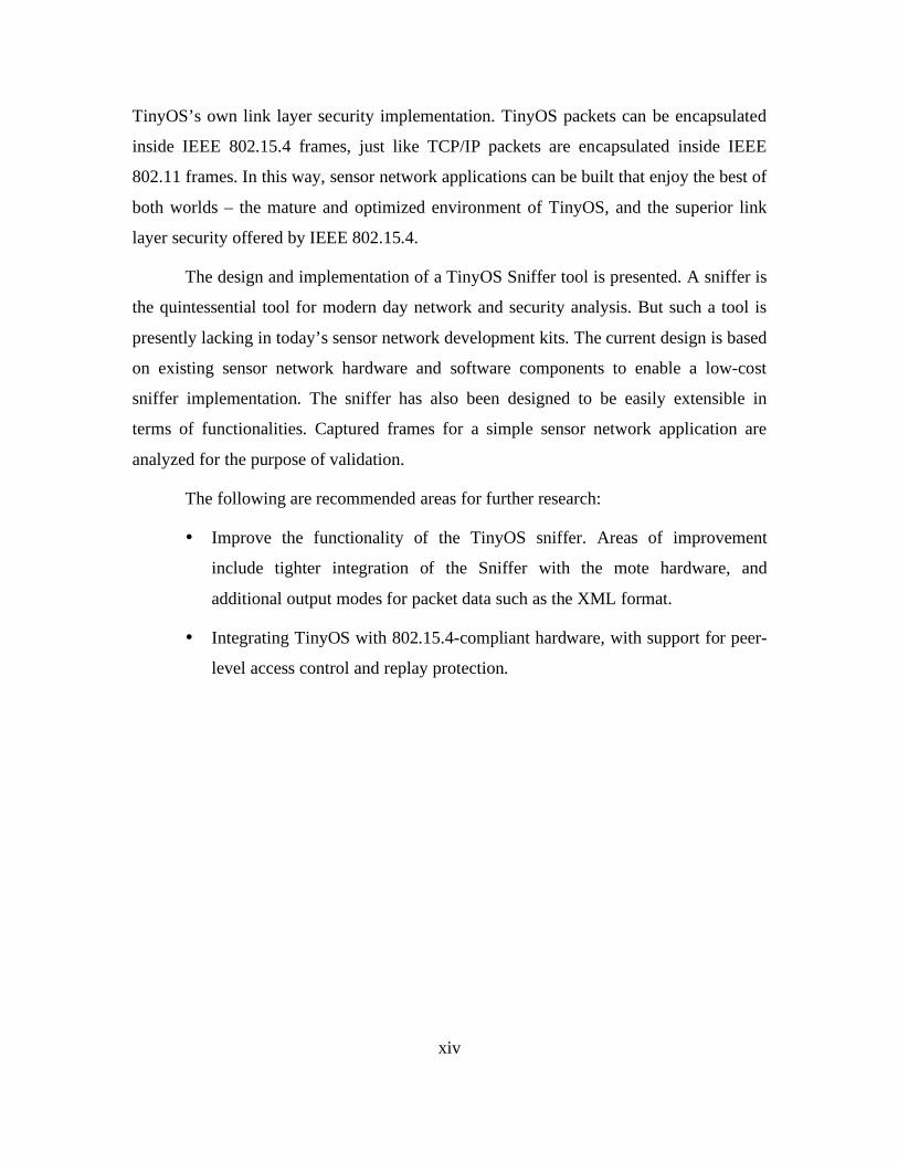
The design and implementation of a TinyOS Sniffer tool is presented. A sniffer is
the quintessential tool for modern day network and security analysis. But such a tool is
presently lacking in today’s sensor network development kits. The current design is based
on existing sensor network hardware and software components to enable a low-cost
sniffer implementation. The sniffer has also been designed to be easily extensible in
terms of functionalities. Captured frames for a simple sensor network application are
analyzed for the purpose of validation.
The following are recommended areas for further research:
• Improve the functionality of the TinyOS sniffer. Areas of improvement
include tighter integration of the Sniffer with the mote hardware, and
additional output modes for packet data such as the XML format.
• Integrating TinyOS with 802.15.4-compliant hardware, with support for peer-
level access control and replay protection.
1
I. INTRODUCTION
A. INTRODUCTION Security in sensor networks is an active but wide-open research field. Initial
research efforts in sensor networks have understandably been focused on functionality,
stability, and cost effectiveness. But past experiences with other wireless technologies
have shown that security will be an equally important factor in deciding the viability of
sensor networks. In order for a sensor network to be resilient to the myriad of network
attacks that it will inevitably face, security must pervade its entire system design. The
good news is that the sensor network is still very much in its infancy, so there are ample
opportunities for researchers to ensure that security is designed into sensor networks, and
that it is done right. The bad news, however, is that since sensor networks have entirely
different physical and network characteristics from conventional wireless networks, they
pose unique security challenges where traditional security techniques cannot be applied
directly. New and innovative approaches must be sought.
B. THESIS OBJECTIVE This thesis examines the current state of sensor network security, assesses its
adequacy, and identifies potential areas of research. The main objective is to understand
the design and implementation issues in realizing a secure deployable sensor network. A
secondary objective is the design and development of a sensor network packet sniffer. A
sensor network packet sniffer will assist in further analyzing and validating some of the
issues identified in this thesis.
C. RELATED WORK Researchers have known about the challenges facing sensor network security
[1,2,3]. These include key establishment and trust setup, secrecy and authentication,
privacy of sensed data, denial-of-service, secure routing, node capture, eavesdropping,
and malicious use of the technology. For denial of service, researchers have found that a
variety of attacks can be mounted at the physical, link, network and transport layers [4].
2
New classes of routing attacks, called sinkhole and HELLO floods, have been devised
[5]. In addition, a variety of ad-hoc and peer-to-peer networking attacks, like the Sybil
attack [6], can be adapted into powerful attacks against sensor networks [7]. Commercial
tools are available for packet sniffing of a IEEE 802.15.4 network [8].
Researchers have studied the security of IEEE 802.15.4, and a few problems have
been found [9]. These include lack of integrity protection for acknowledgement packets,
key management issues, and lack of support for group keying models. Nonetheless, they
conceded that the 802.15.4 security is fundamentally sound, and that proper use of the
security API can lead to secure applications. SNEP (Secure Network Encryption
Protocol), part of the SPINS [10] (Secure Protocols for Sensor Networks) framework,
appears to be an alternative security architecture specifically targeted at sensor networks.
But SNEP was unfortunately not fully specified nor fully implemented.
D. ORGANIZATION The first step to a secure deployable sensor network is to understand the security
from the ground up. Chapters II and III of the thesis examine the link layer security
offered by the two dominant sensor network implementations in the market today,
namely TinyOS and IEEE 802.15.4. Like other wireless networking technologies, the
communications of sensor networks do not enjoy the benefits of physically protected data
links, so the threat of interception by an adversary is always present. Hence, link layer
security is an especially important consideration for wireless sensor networks. Chapter IV
discusses the similarities and differences in the security architecture of TinyOS and IEEE
802.15.4, as well as their strength and limitations. Where applicable, comparisons are
made with IEEE 802.11 Wireless LAN to highlight improvements and lessons learnt.
Next, the design and implementation of a sensor network sniffer is described in
Chapters V and VI. A sniffer is the quintessential tool for network analysis. But such a
tool is presently lacking in today’s sensor network development kits. The current design
is based on existing sensor network hardware and software components to enable a low-
cost sniffer implementation. Captured frames from a simple sensor network application
are analyzed for the purpose of validation.

3
Finally, Chapter VII concludes with a summary of the key points of this thesis,
and recommended areas for further research.

4
THIS PAGE INTENTIONALLY LEFT BLANK

5
II. SECURITY ARCHITECTURE OF IEEE 802.15.4
A. OVERVIEW The IEEE 802.15.4 standard [11] (802.15.4) is also known as the Low Rate
Wireless Personal Area Network (LR-WPAN). It is designed to be a low-cost, low-
complexity and short-range wireless communication network for applications with
limited power and relaxed throughput requirements. Strictly speaking, 802.15.4 defines
protocols not specifically for sensor networks, but for Wireless Personal Area Networks
(WPAN). It is part of the WPAN family of standards that covers a personal operating
space (POS) of typically 10 meters. But it has begun to attract strong interest from the
sensor network community in using these protocols for sensor networks.
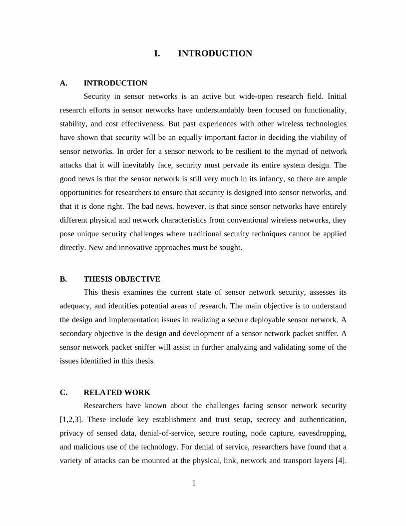
An 802.15.4 network can operate in either a star or peer-to-peer (mesh) topology,
as illustrated in Figure 1. Each node in the network can either be a Full-Function Device
(FFD), or a Reduced-Function Device (RFD).
The FFD embodies all the functionalities of an 802.15.4 device. It can operate in
three roles: a PAN coordinator, a coordinator, or a device. An 802.15.4 network must
include at least one FFD acting as the PAN coordinator in order for the network to form.
On the other hand, an RFD is an extremely simple device that can talk only to an FFD.
RFDs are useful for say, a light switch or a passive infrared sensor. Thus, in a typical
sensor network, the “leaves” of the network can be visualized to be either RFDs or FFDs,
while the gateway or router is an FFD.
Each device in the 802.15.4 network can by addressed by either a 64-bit extended
address, or a 16-bit short address. The former is the global unique address of the device,
analogous to the 48-bit Ethernet address of network interface cards. The latter is a
convenient shorthand in a network-specific setting.
6
Figure 1: Illustration of a Zigbee/802.15.4 network. The green links and nodes show the star topology, while the blue links and nodes show the mesh topology. Through appropriate routing nodes, star and mesh networks can interoperate.
Source: [From 12].
B. RELATIONSHIP WITH ZIGBEE Zigbee [13] is often spoken in the same breath as 802.15.4. They are not the same,
although Zigbee is designed to work in tandem with 802.15.4. Their relationship is
illustrated in Figure 2.
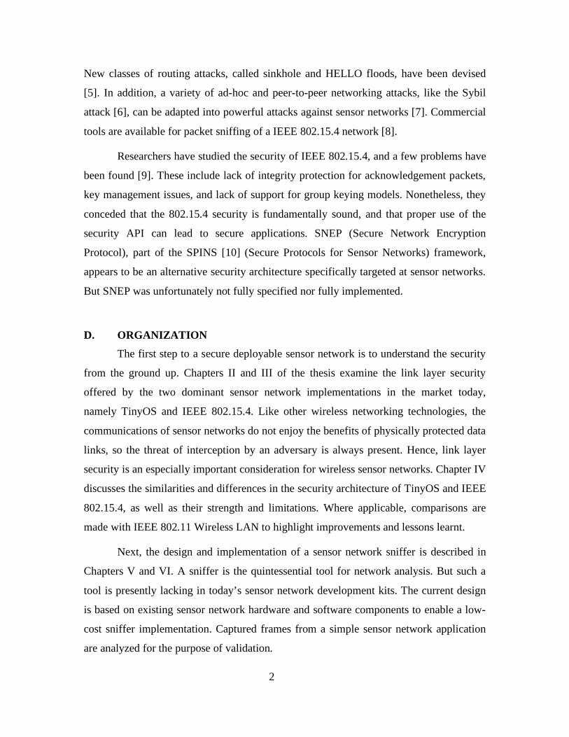
802.15.4 is based on the classic Open Systems Interconnection (OSI) seven-layer
model [14], where it defines the physical layer and the media access control layer. The
physical layer contains the radio frequency transceiver along with its low-level control
mechanism. The media access control layer forms part of the data link layer, and provides
access to the physical channel for all types of transfer. This is the typical way that recent
IEEE 802.x standards are specified. Its purpose is to provide a common and interoperable
communications platform that higher layer protocols can leverage on.
The higher layer protocols are defined by specific applications such as Zigbee.
Zigbee builds on the 802.15.4’s physical and medium access control layers with a
network layer and an application layer that manage routing, discovery, security, and other
network-level functions. Of note, the security services provided by Zigbee include
methods for key establishment, key transport, frame protection, and device management.
7
Figure 2: Relationship between Zigbee and 802.15.4. Note the separation point in the medium access control layer.
Source: [From 12].
As such, the security provided by 802.15.4 can be considered to be link layer
security primarily aimed at node-to-node security, while the security provided by Zigbee
can be considered application layer security primarily aimed at end-to-end security.
Zigbee security is thus analogous to SSH [15], SSL/TLS [16] and IPSec [17].
In section 2.4 of his book [18], Stallings noted that with end-to-end security, the
user data is secure, but the traffic pattern is not, since packet headers must be transmitted
in the clear for the packet to be successfully routed to the destination. User data is
therefore subjected to traffic analysis [19]. To achieve greater security, both link and end-
to-end security are needed. Hence, 802.15.4 security and Zigbee security should
complement but not replace each other.
Karlof, Sastry and Wagner [20] opined that the dominant traffic pattern in sensor
networks is not end-to-end communication, but many-to-one communication, where in-
network processing such as aggregation and duplicate elimination is used to reduce
network traffic and save energy. Since in-network processing requires each intermediate
node to access, modify and suppress the contents of messages, the more appropriate
security mechanism to study should be node-to-node security instead of end-to-end
8
security. For this reason, the analysis of the security of Zigbee stack is outside the scope
of this thesis. Nonetheless, it is recognized that end-to-end security will still have value
for security services like keying.
The following sections discuss key components of the 802.15.4 security
architecture.
C. SECURITY SERVICES
The International Telecommunication Union (ITU) Telecommunication
Standardization Section (ITU-T) Recommendation X.800 [21] defines four classes of
layer 2 security services between communicating open systems, namely authentication,
access control, message confidentiality, and message integrity. 802.15.4 uses the
following terms for its security services: access control, data encryption, frame integrity,
and sequential freshness. In this thesis, the more conventional terms of access control,
message confidentiality, message integrity, and replay protection, respectively are
adopted.
802.15.4 provides all four of these services, but only three of them are specified in
the standard, namely access control, message confidentiality and message integrity. Peer
entity authentication is embedded in message integrity. In addition, an optional fourth
security service, replay protection, is provided by 802.15.4, although one may say that it
can be considered part of message integrity too.
1. Access Control Access control provides the ability for a device to select the other devices with
which it is willing to communicate. At the same time, it also prevents unauthorized
parties from participating in the network. In 802.15.4, access control is implemented by
an access control list (ACL) that each device maintains for the nodes that it is willing to
communicate with. The ACL is explained in more details later.
2. Message Confidentiality Message confidentiality means keeping information secret from unauthorized
observation. In 802.15.4, message confidentiality is achieved through a symmetric cipher,
using a key shared by a group of devices (typically stored as the default key) or using a
key shared between two peers (typically stored in an individual ACL entry). Message
9
confidentiality may be provided on beacon payloads, command payloads, and data
payloads, but not on acknowledgement payloads.
3. Message Integrity Message integrity means protecting the data from unauthorized modification. In
802.15.4, message integrity is achieved by using a message authentication code (MAC).
802.15.4 refers to the message authentication code as a message integrity code (MIC) in
order to differentiate it from the media access control layer, which also abbreviates to
MAC. This is beginning to become the convention used in recent IEEE standards. In this
thesis, however, the cryptographic convention of using MAC as an abbreviation for
message authentication code is adhered to. To avoid any confusion, media access control
is not abbreviated.
A MAC is a key-dependent one-way hash function [22] that is applied over the
entire packet, including the packet headers. The key used to compute the MAC is the
same key used for data confidentiality. Since the MAC depends on the key, the MAC
further provides peer entity authenticity. The MAC may be provided on beacon frames,
command frames, and data frames, but not on acknowledgement frames. Note the
distinction between frame and payload. Encryption is applied to the packet payload,
while MAC is applied to the entire frame, including the headers.
4. Replay Protection (optional) Replay protection uses an ordered sequence of inputs to detect and reject frames
that have been replayed. The sender assigns a monotonically increasing sequence number
to every outgoing packet, and the receiver rejects packets with sequence numbers smaller
than the one it has already received. A receiver can optionally enable replay protection
when encryption is enabled.
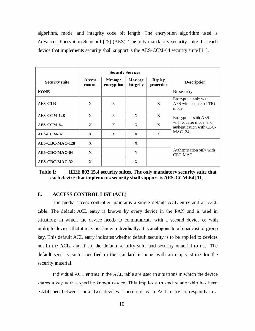
D. SECURITY SUITES
802.15.4 provides the security services via a set of pre-defined security suites (see
Table 1). These security suites will only be used when the application specifies that the
device shall operate in secured mode.
A security suite consists of a set of operations to perform on medium access
control layer frames. The security suite name indicates the symmetric cryptography
10
algorithm, mode, and integrity code bit length. The encryption algorithm used is
Advanced Encryption Standard [23] (AES). The only mandatory security suite that each
device that implements security shall support is the AES-CCM-64 security suite [11].
Security Services
Security suite Access control
Message encryption
Message integrity
Replay protection Description
NONE No security
AES-CTR X X X Encryption only with AES with counter (CTR) mode
AES-CCM-128 X X X X
AES-CCM-64 X X X X
AES-CCM-32 X X X X
Encryption with AES with counter mode, and authentication with CBC-MAC [24]
AES-CBC-MAC-128 X X
AES-CBC-MAC-64 X X
AES-CBC-MAC-32 X X
Authentication only with CBC-MAC
Table 1: IEEE 802.15.4 security suites. The only mandatory security suite that each device that implements security shall support is AES-CCM-64 [11].
E. ACCESS CONTROL LIST (ACL) The media access controller maintains a single default ACL entry and an ACL
table. The default ACL entry is known by every device in the PAN and is used in
situations in which the device needs to communicate with a second device or with
multiple devices that it may not know individually. It is analogous to a broadcast or group
key. This default ACL entry indicates whether default security is to be applied to devices
not in the ACL, and if so, the default security suite and security material to use. The
default security suite specified in the standard is none, with an empty string for the
security material.
Individual ACL entries in the ACL table are used in situations in which the device
shares a key with a specific known device. This implies a trusted relationship has been
established between these two devices. Therefore, each ACL entry corresponds to a

11
trusted device, and consists of its PAN identifier, its 64 bit extended address, its 16 bit
short address (or 0xffff if this address is not known), and its security suite and related
security material. When replay protection is enabled, the security material includes a high
water mark of the most recently received sequence number. There can be a maximum of
255 entries in the ACL table.
F. MODE OF OPERATION The media access controller can be set in one of three security modes, namely
unsecured mode, ACL mode, and secured mode. Unsecured mode is self-explanatory.
ACL mode does not perform any cryptographic operations on the frames, but provides
only a means for the device to indicate to the application whether the frame comes from a
device in the ACL table. Secured mode utilizes the ACL functionality and also provides
cryptographic protection on incoming and outgoing frames.
When the media access controller receives a packet from the application to send
in secured mode, the ACL is consulted to find an entry that matches the destination
address of the packet. If there is a match, the security material in the ACL entry is used to
encrypt and/or authenticate the packet, according on the security suite specified in the
ACL entry. If there is no match, then the default ACL entry is checked to see if default
security is to be applied. If this setting is true, then the default security suite and security
material is used to process the packet. Note that this can mean no security. Otherwise, the
media access controller reports an error to the application.
On packet reception, the media access controller consults a flag in the packet
header to determine if any of the security suites have been applied to the packet. If no
security has been applied, the packet is passed on to the application as is. Otherwise, a
process similar to the sending process is used, but this time based on the source address.
If replay protection is enabled, the media access controller also verifies that the sequence
number of the packet is greater than the one stored at the corresponding ACL entry. If it
is, the ACL entry is updated with the new sequence number as the new high water mark.
Otherwise, an error is reported to the application.
12
G. NONCE OR INITIALIZATION VECTOR (IV) An important aspect of data confidentiality is semantic security [25]. It means that
besides preventing plaintext recovery, the encryption scheme should also prevent
adversaries from learning even partial information about the plaintext. One implication of
semantic security is that encrypting the same plaintext twice must result in two different
ciphertexts. A common technique to achieve this is to use a nonce, or more commonly
called the initialization vector (IV), as a side input to the cipher in addition to the key. So
long as the IV is unique for each encrypted packet, then no two packets can be encrypted
to the same ciphertext, even if they have the same data, which is not an uncommon
situation in computer networking. Since the receiver must use the IV to decrypt
messages, the security of most encryption schemes do not rely on the IV being secret.
Hence, the IV is typically sent in the clear with the encrypted packet. The IV is often a
monotonically increasing large number. Another strategy to generate IV is to randomly
choose from an n-bit value. But by the birthday paradox, it is likely that the first
repetition will occur after 2n/2 packets have been sent. On the other hand, if the IV is
chosen from an n-bit counter, then the first repetition will not occur before 2n+1 packets
have been sent. Hence, the later strategy is often the more popular.
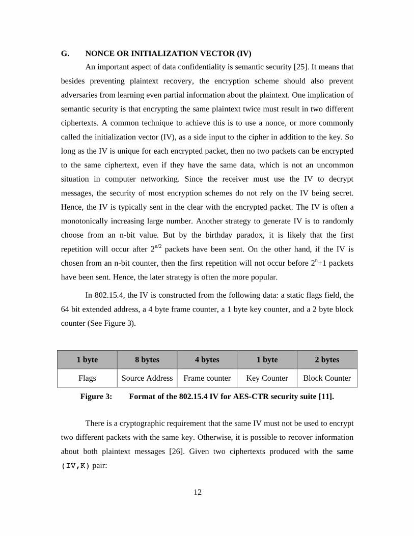
In 802.15.4, the IV is constructed from the following data: a static flags field, the
64 bit extended address, a 4 byte frame counter, a 1 byte key counter, and a 2 byte block
counter (See Figure 3).
1 byte 8 bytes 4 bytes 1 byte 2 bytes
Flags Source Address Frame counter Key Counter Block Counter
Figure 3: Format of the 802.15.4 IV for AES-CTR security suite [11]. There is a cryptographic requirement that the same IV must not be used to encrypt
two different packets with the same key. Otherwise, it is possible to recover information
about both plaintext messages [26]. Given two ciphertexts produced with the same
(IV,K) pair:
13
C1 = AES(IV,K) ⊕ P1
C2 = AES(IV,K) ⊕ P2
C1 ⊕ C2 = AES(IV,K) ⊕ P1 ⊕ AES(IV,K) ⊕ P2 = P1 ⊕ P2
Given the well-known structure of network messages, recovering the XOR of the
two plaintexts makes it significantly easier to recover the two plaintexts.
The frame counter and key counter are key (pun unintended) in ensuring that this
will not be the case. The frame counter is maintained by the media access controller,
while the key counter is controlled by the application. The media access controller
increments the frame counter for every encrypted packet sent. When the frame counter
reaches the maximum value and rolls over, the media access controller notifies the
application with an error. The application must increment the key counter to continue
encrypting packets.
When both the frame counter and key counter are exhausted, no further
encryption is possible with this key, until a new key is established.
Instead of sending the entire IV with the encrypted payload, only the frame
counter and key counter are pre-pended to the encrypted payload and sent in the clear.
The rest of the fields of the IV can be derived from the packet.
In previous sections, a sequence number that is used in replay protection has been
alluded to. In 802.15.4, this sequence number is the five byte value constructed from the
concatenation of the frame counter and the key counter.
H. SUMMARY
The basic security architecture of 802.15.4 was presented. A distinction has been
made between application-layer security offered by Zigbee, and the link-layer security
offered by 802.15.4. The discussion includes its security services and security suites, as
well as its mode of operation, and the specification of the access control list and
initialization vector. Overall, 802.15.4 has a comprehensive set of services to enable

14
secure link-layer communications in sensor networks. In the next chapter, the security
architecture of TinyOS will be presented.
15
III. SECURITY ARCHITECTURE OF TINYOS
A. OVERVIEW TinyOS is a popular research platform for sensor networks, frequently used in
conjunction with the Crossbow motes [27] as the preferred microprocessor and radio
hardware. From its website [28],
TinyOS is an open-source operating system designed for wireless embedded sensor networks. It features a component-based architecture which enables rapid innovation and implementation while minimizing code size as required by the severe memory constraints inherent in sensor networks. TinyOS's component library includes network protocols, distributed services, sensor drivers, and data acquisition tools – all of which can be used as-is or be further refined for a custom application. TinyOS's event-driven execution model enables fine-grained power management yet allows the scheduling flexibility made necessary by the unpredictable nature of wireless communication and physical world interfaces.
The topology of a sensor network based on TinyOS devices depends entirely on
the application and the networking stack used. A TinyOS application, and indeed parts of
TinyOS itself, is programmed in an object-oriented componentized C language extension,
called nesC [29]. For example, Surge is a popular mesh networking stack. For Surge-
based applications, the topology is similar to one based on 802.15.4, but it does not have
an implicit hierarchy of nodes like 802.15.4 does.
A TinyOS device is addressed by a 16-bit address, augmented with an 8-bit group
ID. The group ID is analogous to the network address for a group of cooperating nodes. It
allows multiple distinct groups of motes to share the same radio channel. In addition,
TinyOS implements the Active Message (AM) system. AM types are analogous to port
numbers in TCP/IP. Each TinyOS packet includes an 8-bit AM type in the header (see
Figure 4).
Early versions of TinyOS did not have security built in at all. In late 2004, the
developers of TinyOS introduced TinySec [30], a lightweight generic link layer security
package that developers can easily integrate into their TinyOS applications. The authors
foresee that TinySec will cover the basic security needs of all but the most security
16
critical applications. To enable TinySec in TinyOS, the application needs to specify
TINYSEC=true on the command line to make, or in the Makefile. Unfortunately, at
this moment, TinySec only works in the TOSSIM simulator and the Mica and Mica2
motes [38]. It has not yet been ported to the MicaZ and Telos motes.
Since the main focus of this thesis is on security, henceforth, when the term
“TinyOS” is used, it is meant to be TinyOS with TinySec enabled.
The following paragraphs discuss the key components of the TinyOS security
architecture. Because TinyOS is not a formal specification like 802.15.4, there is no
official documentation on TinySec. Almost all the information discussed here is taken
from [20,30,38] and the TinyOS source code, which can be downloaded from [28].
B. SECURITY SERVICES The security provided by TinyOS centers on message integrity and message
confidentiality. As in 802.15.4, peer entity authenticity is embedded in message integrity
through the use of a MAC. Unlike 802.15.4, however, TinyOS does not explicitly provide
access control via an ACL.
TinyOS supports two security options: authenticated-encryption (TinySec-AE)
and authentication-only (TinySec-Auth). The former encrypts the data payload, then
computes the MAC over the packet header and encrypted payload. The latter does not
encrypt the data payload, but only computes the MAC over the packet header and data
payload. The default security mode of a TinySec-enabled application is TinySec-Auth.
The TinySec mode is indicated in the upper 2 bits (MSB) of the length field of the packet
header. This modification is harmless because the maximum size of the data field in a
TinyOS packet is 29 bytes, i.e., at most 5 bits of the length field will be used.
It can be seen from Figure 4 that the TinyOS and the TinySec-Auth packets do
not have a field for the source address. So it is impossible for the receiver to know where
the packet came from. Source address is only included in the TinySec-AE packet, and
that was primarily for the benefit of increasing the diversity of the IV. Hence, if an
application wants to implement ACL-based access control, then it can only do so with
TinySec-AE.

17
Figure 4: TinyOS packet formats. The byte sizes of the fields are indicated in parentheses. The shaded fields are protected by the MAC. Note that the Group field is omitted from the TinySec packet formats – group membership is implicit in the
knowledge of the secret key [20]. C. SECURITY PRIMITIVES
1. Message Authentication Codes (MAC) As in 802.15.4, TinySec uses the cipher block chaining construct, CBC-MAC
[24], for computing and verifying MACs. The MAC is 32-bit long, and is computed over
the headers as well as payload of the packet. The authentication key is 64 bits long.
While the security of the MAC is directly related to the length of the MAC, the
developers argued in that given the expected low data rate of the sensor network, a 32-bit
MAC may provide an adequate level of security against blind forgeries. Adversaries
cannot determine off-line if he has successfully forged a valid MAC for a particular
message, hence any forgery attempts will be “blind”. For example, if an adversary tries to
flood a 19.2 kb/s channel with blind forgery attempts, it may take him over 20 months to
succeed, notwithstanding the fact that he would have effectively conducted a denial-of-
service (DoS) attack on the network and exhausted the battery of the device long ago.
Dest
(2)
AM
(1)
Len
(1)
Src
(2)
Ctr
(2)
Encrypted Data
(0..29)
MAC
(4)
IV
(a) TinySec-AE packet format
Dest
(2)
AM
(1)
Len
(1)
Data
(0..29)
MAC
(4)
(b) TinySec-Auth packet format
Dest (2)
AM (1)
Grp (1)
Len (1)
Data (0..29)
CRC (2)
(c) TinyOS packet format
18
Furthermore, sustained forgery attempts can be pre-empted through simple
heuristics. For example, nodes can signal the base station when the rate of MAC failures
exceeds some reasonable threshold. Such countermeasures would mitigate the need for a
longer MAC. Unfortunately, TinyOS leaves the implementation of such countermeasures
to the application.
2. Encryption Scheme The default cipher used in TinyOS is Skipjack in 64-bit cipher block chaining
(CBC) mode, in conjunction with an eight byte IV, using a 64-bit encryption key. RC5 is
also feasible. These two ciphers were found to be most appropriate for software
implementation on embedded microcontroller as far as implementation efficiency and
performance are concerned. The TinyOS source code includes implementation for both
Skipjack and RC5. AES was later deemed to be equally suitable as well.
The choice of using CBC mode over stream cipher was primarily because with
regards to semantic security, CBC mode is believed to degrade more gracefully when IV
reuse occurs. This is an important consideration for TinyOS, because between two
communicating nodes, the IV could be as small as a 16-bit value. If the IV is long enough
so that it is not expected to repeat in a long time, then a stream cipher like AES-CTR
performs much better. An additional advantage is that the same block cipher code can be
used for the message authentication code (CBC-MAC), thus saving considerable code
space.
3. Initialization Vectors (IV) As in 802.15.4, the encryption scheme uses an IV to achieve semantic security.
The format of the IV is shown in Figure 4a. The first four bytes of the IV are borrowed
from the existing header fields of the TinyOS packet: the destination address, the AM
type, and the length of the packet. The last four bytes are comprised of the source address
and a 16-bit counter. The counter is initialized to zero, then incremented by one after
every message sent.
The last four bytes of the IV is chosen in this way to maximize the number of
packets each node can send before there is a global repetition of the IV. That is, each
node can send at least 216 packets before IV reuse occurs. For a network of n nodes, this
results in n.216 packets before IV reuse occurs in the network.
19
The developers felt that this IV design should provide adequate security. Since
sensor networks must conserve power to be long-lived, the average packet rate in most
sensor networks will be very low – on the order of one packet per minute. At one packet
per minute, IV reuse will not occur for over 45 days. In addition, the selection of CBC
encryption mode further mitigates the risk of information leakage when IV reuse occurs.
In short, information may only leak when one node sends two different packets with the
same first eight bytes and IV, to the same destination, with the same AM type, and of the
same length.
D. SUMMARY The basic security design of the TinyOS, or more specifically TinySec, was
presented. The security provided by TinyOS centers on message integrity and message
confidentiality. Peer entity authenticity is embedded in message integrity through the use
of a MAC. On the other hand, TinyOS does not explicitly provide access control via an
ACL. There are 2 security modes: authenticated-encryption, and authenticated only.
Security primitives such as message authentication codes, encryption scheme and
initialization vector has also been discussed. With the background information on
802.15.4 and TinyOS now in place, the next chapter will discuss their similarities,
differences, strength and limitations.

20
THIS PAGE INTENTIONALLY LEFT BLANK
21
IV. ANALYSIS OF 802.15.4 AND TINYOS SECURITY
In this chapter, the similarities and differences between the security designs of
802.15.4 and TinyOS will be examined, and their strength and limitations discussed.
Where applicable, lessons learned from another wireless standard, IEEE 802.11 Wireless
LAN [31] (802.11), will be applied to assess the adequacies of 802.15.4 and TinyOS
security.
A. MODULARITY VS OPTIMIZATION The objectives of 802.15.4 and TinyOS are very similar: ease of deployment,
reliability and robustness, short-range operations, extremely low cost, and long battery
life. But they are quite different in the way they are architected. The contrast can be
summarized as Modularity versus Optimization.
802.15.4 follows the tried-and-tested layered protocol approach of the seven-layer
OSI model. 802.15.4 specifies the lower 2 layers, namely physical and media access
control. In this regard, it is very similar to 802.11. The inherent modularity of this model
allows powerful higher layer specifications like Zigbee to export their own services,
which applications can easily take advantage of. The downside is added code complexity,
memory overhead, and processing delay in the handling of packets as they traverse the
layers – a luxury that some sensor network applications can ill afford.
On the other hand, TinyOS resembles more of a toolkit or library for fast
prototyping of sensor network applications. The OS is built-in to abstract the underlying
hardware and support an event-driven framework. Unlike 802.15.4, TinyOS is tailor-
made for sensor networks, and targets devices with limited memory and power. Many of
the design decisions were made under the constraints of significant resource limitations.
Betweem the two, TinyOS would easily offer a more optimized and energy efficient
sensor network solution. The cost to pay for this optimization is the loss of some
implementation transparency, the ability to modularize the solution, and perhaps some
degree of assurances especially for applications where security is critical.

22
It should be noted that 802.15.4 is intended for hardware implementation on a
dedicated radio chip, while TinyOS does not require dedicated hardware. The developers
of TinyOS do not see this as a handicap. They claim that with sufficient engineering
efforts, it is possible to encrypt and authenticate all communications entirely in software
without major performance degradation. This result is a testament to the optimization
possible in TinyOS.
As of today, the only radio chip that claims to be fully 802.15.4 compliant is the
Chipcon CC2420 (CC2420) [32,33], currently used in Crossbow’s MicaZ and the TelosB
motes. It operates in the 2.4 GHz frequency band with a data rate of 250 kbps.
B. KEYING MECHANISM AND IV Neither 802.15.4 nor TinyOS addresses the issue of the keying, that is the manner
in which keys are generated, distributed, and securely stored (or destroyed). Section
5.4.6.1 in [11] states,
the security mechanisms in this standard are symmetric-key based using keys provided by higher layer processes. The management and establishment of these keys is the responsibility of the implementer. The security provided by these mechanisms assume[s] the keys are generated, transmitted, and stored in a secure manner.
Given that keying is generally considered a higher layer service, this position is
understandable. But keying has a critical inter-dependency with one aspect of link layer
security: the IV. Recall that to achieve semantic security, a node must not use the same
IV with the same key for encryption. This is especially true when the IV is used with a
stream ciphers like AES-CTR used by 802.15.4, or RC4 used by 802.11. 802.11 used a
woefully inadequate 24-bit IV. On a network with a moderate load, this IV space was
exhausted within a few hours. When there are multiple hosts within the wireless network,
the situation is exacerbated since they all share the same encryption key.
Both 802.15.4 and TinyOS learned this lesson: 802.15.4 uses a much longer IV,
up to 40 bits. While TinyOS limits itself to a shorter IV, it tries to mitigate the risk of
information leakage through the use of CBC encryption mode rather than naively use a
stream cipher.

23
Table 2 illustrates the theoretical IV reuse periods for TinyOS and 802.15.4
between 2 communicating nodes for the various data rates shown. The packet sizes
chosen are the maximum packet sizes, so that if the actual packets are smaller, then the
IV reuse periods will be shorter than those shown. The IV length of 40 bits for 802.15.4
assumes both the frame counter (4 bytes) and the key counter (1 byte) are in use.
IV reuse period
Data rate
(kb/s)
Packet size
(bytes)
Maximum throughput
(pkt/s) IV
length 100%
duty cycle At 1
pkt/min Mica2[34] 38.4 120 9.1 min TinyOS MicaZ[35] 250
41 780
16 bits 1.4 min
45.5 days
20 20 1743 yrs 40 40 872 yrs 802.15.4 250
128
250
40 bits
139 yrs
>2m yrs
Table 2: IV reuse periods for TinyOS and 802.15.4 between two communicating nodes.
It can be seen from the table that in the worse case, i.e., 100% duty cycle, it will
take a matter of minutes in TinyOS for IV reuse to occur, while it will take hundreds of
years for 802.15.4. Even in the optimistic case of one packet per minute, it will take
slightly more than 45 days in TinyOS for IV reuse to occur, while it will take more than 2
million years for 802.15.4.
This implies that for TinyOS to avoid IV reuse, a new key will have to be
established every 45 days. In practice, one may re-key well before that period runs out.
On the other hand, re-keying may not even be an issue for 802.15.4, since the IV reuse
period will be longer than the lifetime of almost all applications.
It is stated here that the IV length of TinyOS is 16 bits. This warrants some
discussion. On paper, TinyOS states that the IV is 8 bytes (see Figure 4a). But between
two communicating nodes, only the last 2 bytes will be constantly variable. The
destination address, source address and AM type are most likely fixed. Theoretically, the
length field may also be variable, but most sensory messages will be fixed length, or have
low variances in their lengths. Hence, it can be concluded that the IV length is effectively
only 16 bits.

24
Even if a constantly varying length field is taken into consideration, it will only
add five bits to the IV, not eight bits, because the maximum data field size is 29 bytes.
This translates into a 32 times increase in the IV reuse period. For the optimistic case of
one packet per second, it becomes a more respectable 4 years. But in the worst case, it is
still only in the order of hours.
To be fair, it was a conscious design decision by the developers of TinySec to
choose a 16-bit IV, and accept that IV reuse will occur, because a longer IV was deemed
to add unacceptable overhead to the TinyOS packet size. Thus, CBC mode was
specifically chosen because of its robustness to information leakage when IVs repeat. In
short, information only leaks when two packets with the same first 8 bytes and IV are
sent, assuming the rest of the fields are identical.
In summary, the long IV length of 802.15.4 means that the IV is unlikely to be
exhausted in the lifetime of any application. Hence 802.15.4 applications can get away
with not having to contend with re-keying issues. On the other hand, the short IV length
combined with CBC mode may be sufficient security for most TinyOS applications. For
applications requiring higher assurances, however, either a robust re-keying mechanism
must be used, or TinyOS’s IV must be customized to a longer length.
C. ACCESS CONTROL 802.11 did not specify a mechanism for access control within the wireless
network. Most vendors choose to implement Ethernet address-based access control list at
the access point. Unfortunately, the Ethernet address alone does not provide a strong
enough identity. Attackers can sniff Ethernet addresses wirelessly and then spoof them
via software [36] to impersonate legitimate clients. Encrypting the wireless traffic via a
shared key may exclude adversaries without the key, but once the key is compromised,
the adversary will again be able to impersonate any legitimate client.
Access control is an important consideration in sensor networks, because sensor
network nodes are susceptible to physical capture. Therefore if the access control of the
network is based on a single shared key, then once a node is captured and the key
compromised, the access control for the entire network fails. The remaining sensor nodes
25
may have to be recovered and securely re-keyed with a new shared key – not always a
feasible course of action. On the other hand, if the access control is based on pair-wise
keys, then capturing a node will just violate the access control relationship with its peers,
not the entire network. If a node is suspected of being captured, the network can simply
instruct the captured node’s immediate peers to expel the node from their access control
list. There is no need to re-key the entire network. Hence, access control via an ACL with
pair-wise keying should be the preferred access control mechanism for sensor networks.
TinyOS enforces access control with a MAC computed from a network-wide
shared key. On the other hand, 802.15.4 can potentially offer very fine-grained access
control. Each device can hold up to 255 entries in its ACL table, one for each trusted
peer. Each trust relationship can have its individual security settings; authenticate-only,
encrypt-only, or authenticate-encrypt.
An interesting scenario arises when an FFD is physically captured. In this case, an
attacker can make use of the captured FFD to impersonate as a PAN coordinator, thus
potentially routing all traffic through it. One way to mitigate this threat is to ensure that
the edge devices that are susceptible to physical capture are only RFDs. Another way is
to employ countermeasures to detect unauthorized or duplicate PAN coordinators.
It must be pointed out, however, that the 802.15.4 specification does not make it
mandatory to support the full 255 entries in the ACL table, and in the manner that the
specification describes. Figure 5 shows the CC2420 RAM memory map. It can be seen
that the CC2420 does not have an ACL table. Instead, it has 2 keys. The application may
choose to use one for transmit and the other for receive, or use a single key for both
transmit and receive. These keys do not have an address associated with them. Therefore,
these keys are more akin to the default ACL entry in the 802.15.4 specifications, and can
only effectively support group keying.

26
Figure 5: Chipcon CC2420 RAM memory map. Source: [From 33]
D. MESSAGE INTEGRITY In 802.11, message integrity is only protected by a CRC-32 checksum, even when
WEP is turn on. Researchers have shown that it is possible to modify WEP encrypted
packets in transit without detection, because the CRC checksum is an unkeyed function
of the message [37]. The fix is to use a cryptographically secure MAC.
Both 802.15.4 and TinyOS uses a MAC to protect the integrity of their encrypted
messages. It is an accepted wisdom that the security of the MAC is directly related to the
length of the MAC. 802.15.4 applications can use up to 128-bit MAC. CC2420 supports
128-bit MAC only. This is clearly superior to TinyOS’s 32-bit MAC. TinyOS
applications requiring higher assurances should implement countermeasures to prevent an
attacker from making too many blind forgery attempts.
27
E. ENCRYPTION SCHEMES The notable difference between the encryption schemes of 802.15.4 and TinyOS,
is that 802.15.4 uses a stream cipher, AES-CTR, and a long IV to avoid the issue of IV
reuse, while TinyOS uses a 64-bit block cipher in CBC mode with a shorter IV to
mitigate the risk of information leakage associated with IV reuse. The key length of AES
can be up to 128 bits long, and CC2420 has hardware cryptographic support for 128-bit
keys only. It is reasonable to conclude that 802.15.4 should provide a higher degree of
assurance as far as message confidentiality is concerned.
Note that TinyOS does not have an encrypt-only mode. This is no great loss.
From the discussion in the previous section, the integrity of an encrypted packet cannot
be guaranteed by its CRC checksum. A corollary is that encryption should not be used
without a MAC if its integrity needs to be guaranteed. Hence, TinyOS only supports
authenticate-only and authenticate-encrypt. Researchers have cautioned against using
802.15.4’s AES-CTR security suite [9]. They argued that a simple, single-packet denial-
of-service (DoS) attack can be mounted on a 802.15.4 network that uses the AES-CTR
security suite with replay protection enabled.
F. REPLAY PROTECTION TinyOS explicitly omitted replay protection in the security architecture. The main
reason is to avoid the extra memory needed to keep the sequence numbers for every node
that a receiver communicates with. Another reason is that the developers believe that
replay protection is better and more efficiently handled by the application, which has
more intimate knowledge of the overall topology and communications pattern of the
network.
It is generally a good idea to have replay protection in link layer security. 802.11
did not have replay protection; hence, messages could be intercepted and replayed
without modification. The result can be denial-of-service attacks, or it can be used as a
launching pad for other attacks, like the man-in-the-middle attacks.
802.15.4 specifies optional replay protection. On paper, peer-to-peer replay
protection should work very well under the specification. But researchers have found that
28
network shared keying using the default ACL entry to be incompatible with replay
protection. This is because the receiver can only keep a single sequence number in the
default ACL entry as the high water mark while receiving packets from many sources,
each maintaining their own sequence numbers.
It must be pointed out that, as can be seen from Figure 5, CC2420 does not have
provision for a replay counter in its RAM memory space. So any replay protection will
have to be implemented in the application space – just like TinyOS. Therefore, one can
conclude that replay protection is currently absent from today’s sensor network link layer
security, until another radio chip comes along that supports this important feature.
G. SUMMARY The security of 802.15.4 and TinyOS was analyzed and compared in five broad
categories: IV length, access control, message integrity, encryption scheme, and replay
protection. In general, 802.15.4 offers higher assurance in terms of cryptographic
strength, message integrity, and information leakage from IV reuse. TinyOS applications
will need robust re-keying support and countermeasures against forgery attempts to make
up the difference. But they both lack effective peer-level access control and replay
protection – both important aspects of sensor network security.
To validate this security analysis, a sensor network sniffer is needed. A sniffer is
the quintessential tool for modern day network and security analysis. But such a tool is
presently lacking in today’s sensor network development kits. In the following chapters,
the design and implementation of a TinyOS sensor network sniffer will be presented.
29
V. ANATOMY OF THE TINYOS SNIFFER
In the previous chapters, the link-layer security design of TinyOS and 802.15.4
was described and analyzed. To validate the analysis, we need to use a sensor network
sniffer. A sniffer is the quintessential tool for network analysis. But such a tool is
presently lacking in today’s sensor network development kits. In the following chapters,
we will present the design and implementation of a TinyOS sensor network sniffer. The
current design is based on existing sensor network hardware and software components to
enable a low-cost sniffer implementation.
To understand how the sniffer works, it is necessary to first understand how
TinyOS handles incoming network messages, and hence the hardware and software
components necessary to implement such a sniffer.
A. TINYOS FILTERING MECHANISM A TinyOS packet has the format shown in Figure 4c. The fields of interest are the
following:
1. Destination Address The destination address refers to the 16-bit node address of the mote. It is
programmed into the mote along with the TinyOS application when the following
command is issued: make <platform> re|install,<n> <programmer>,<port>
where <n> is the 16-bit node address. The address 0 is typically reserved for the
base station mote.
2. Group ID The group ID is analogous to the network address for a group of cooperating
motes. It allows multiple distinct groups of motes to share the same radio channel. The
group ID can be set by defining the preprocessor symbol DEFAULT_LOCAL_GROUP. For
example, this symbol can be located in the MakeXbowlocal file in the tinyos-
1.x/contrib/xbow/apps directory. This file is automatically included in the
compilation of almost all TinyOS programs in the tinyos-1.x/contrib/xbow/apps
directory. The default group ID is 0x7D.
30
3. AM Type TinyOS implements the Active Message (AM) system. AM types are analogous
to port numbers in TCP/IP. Different applications may use different AM types. For
example, for the Surge_Reliable application, the AM type is defined in the Surge.h
header file: enum { AM_SURGEMSG = 17 };
TinyOS automatically filters incoming packets by matching the destination
address in the packet header with the node address of the mote. If the node address is 0,
then TinyOS skips this step – the mote is effectively operating in promiscuous mode. If
the destination address matches the node address, then the entire packet, including the
header, is passed on to the application. It is the application’s responsibility to handle the
group ID and AM fields.
In summary, a TinyOS sniffer can simply be a mote programmed with a node
address of 0, and an application that ignores the group ID and AM fields (assuming no a-
priori knowledge of either of them).
B. COMPONENTS OF THE SNIFFER The TinyOS sniffer is based on readily available hardware and software
components, and a Java-based application analogous to tcpdump [39].
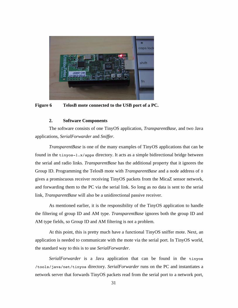
1. Hardware components The hardware platform is simply an off-the-shelf mote connected to a PC. The
traditional connection is via the MIB510 programming board to a PC’s serial port. The
TelosB mote offers a more convenient on-board USB connector that plugs directly into
the PC for both the power and serial connections; hence, a more compact solution (see
Figure 6). Connecting via the MIB510 would require not only an external serial cable, but
also an external power supply for the MIB510 programming board. However, the
message format forwarded by a Mica, MicaZ, or TelosB mote is quite different. So the
application will have to decode the message appropriately according to the hardware
used.
31
Figure 6 TelosB mote connected to the USB port of a PC.
2. Software Components The software consists of one TinyOS application, TransparentBase, and two Java
applications, SerialForwarder and Sniffer.
TransparentBase is one of the many examples of TinyOS applications that can be
found in the tinyos-1.x/apps directory. It acts as a simple bidirectional bridge between
the serial and radio links. TransparentBase has the additional property that it ignores the
Group ID. Programming the TelosB mote with TransparentBase and a node address of 0
gives a promiscuous receiver receiving TinyOS packets from the MicaZ sensor network,
and forwarding them to the PC via the serial link. So long as no data is sent to the serial
link, TransparentBase will also be a unidirectional passive receiver.
As mentioned earlier, it is the responsibility of the TinyOS application to handle
the filtering of group ID and AM type. TransparentBase ignores both the group ID and
AM type fields, so Group ID and AM filtering is not a problem.
At this point, this is pretty much have a functional TinyOS sniffer mote. Next, an
application is needed to communicate with the mote via the serial port. In TinyOS world,
the standard way to this is to use SerialForwarder.
SerialForwarder is a Java application that can be found in the tinyos
/tools/java/net/tinyos directory. SerialForwarder runs on the PC and instantiates a
network server that forwards TinyOS packets read from the serial port to a network port,

32
and vice versa. Typically, it is used to allow applications to communicate with the mote
via a network interface instead of a serial interface – this is especially useful for
distributed network clients, or Java clients like Surge.
The final piece of the puzzle is an application that reads the packet from Serial
Forwarder, extracts the protocol and application information, and outputs the information
in a usable form. There is no such tool in current TinyOS development kits. For this
reason, the Java application Sniffer has been developed. The design and implementation
of Sniffer will be discussed in the next chapter.
Figure 7 illustrates the block diagram of the sniffer.
Figure 7 Block diagram of TinyOS Sniffer.
C. SUMMARY The TinyOS packet filtering mechanism was discussed, and explained how it can
be used for the purpose of frame capture. The necessary hardware and software
components of a TinyOS sniffer was also presented. However, an application,
Sniffer.java, is still needed that reads the packet from Serial Forwarder, extracts the
protocol and application information, and outputs the information in a usable form. This
will be discussed in the next chapter

33
VI. DESIGN AND IMPLEMENTATION OF THE SNIFFER APPLICATION
In addition to the analysis of the security architectures of 802.15.4 and TinyOS,
the main development effort in this thesis is the design and implementation of Sniffer.
This is a multi-threaded, tcpdump-like application that reads raw packets from Serial
Forwarder, extracts the protocol and application layer information, and outputs it in a
usable form.
The developmental paradigm of TinyOS is that mote applications running on the
motes are written in nesC, while user applications running on the PC are written in Java.
Keeping in line with this paradigm, Sniffer is also written in Java.
The remainder of this chapter explains the Sniffer application in more details. To
follow the discussion, some working knowledge of Java is assumed, e.g. how to run Java
programs, what are Java classes etc.
A. USAGE Sniffer is a command line tool with usage as follows:
usage: java Sniffer [-m mica|micaz|telos] [-h host] [-ob filename]
[-?] [-p port] [-l filename] [-oc filename] -m <mica|micaz|telos> Specifies TOS message format when auto-
detection fails. -? Print this help text. -h <host> The host running Serial Forwarder. Can be
a valid hostname or IP address. Default is local host.
-l <filename> Log screen output to file. -ob <filename> Output to file in raw binary format. -oc <filename> Output to file in CSV format. -p <port> Network port used by Serial Forwarder.
Default is 9001.
The meaning of some of these options will become clear as the implementation of
the program is explained.
34
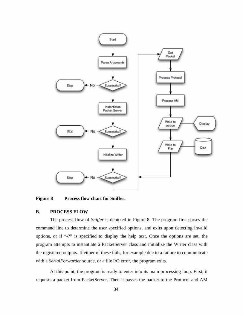
Figure 8 Process flow chart for Sniffer.
B. PROCESS FLOW
The process flow of Sniffer is depicted in Figure 8. The program first parses the
command line to determine the user specified options, and exits upon detecting invalid
options, or if “-?” is specified to display the help text. Once the options are set, the
program attempts to instantiate a PacketServer class and initialize the Writer class with
the registered outputs. If either of these fails, for example due to a failure to communicate
with a SerialForwarder source, or a file I/O error, the program exits.
At this point, the program is ready to enter into its main processing loop. First, it
requests a packet from PacketServer. Then it passes the packet to the Protocol and AM
35
classes in sequence to process the protocol and application layer information respectively.
Finally, the processed packet is passed to the Writer class for output to the screen, and is
optionally written to file in a variety of formats if the user so specifies. The process loop
continues indefinitely until the user terminates with Ctrl-C.
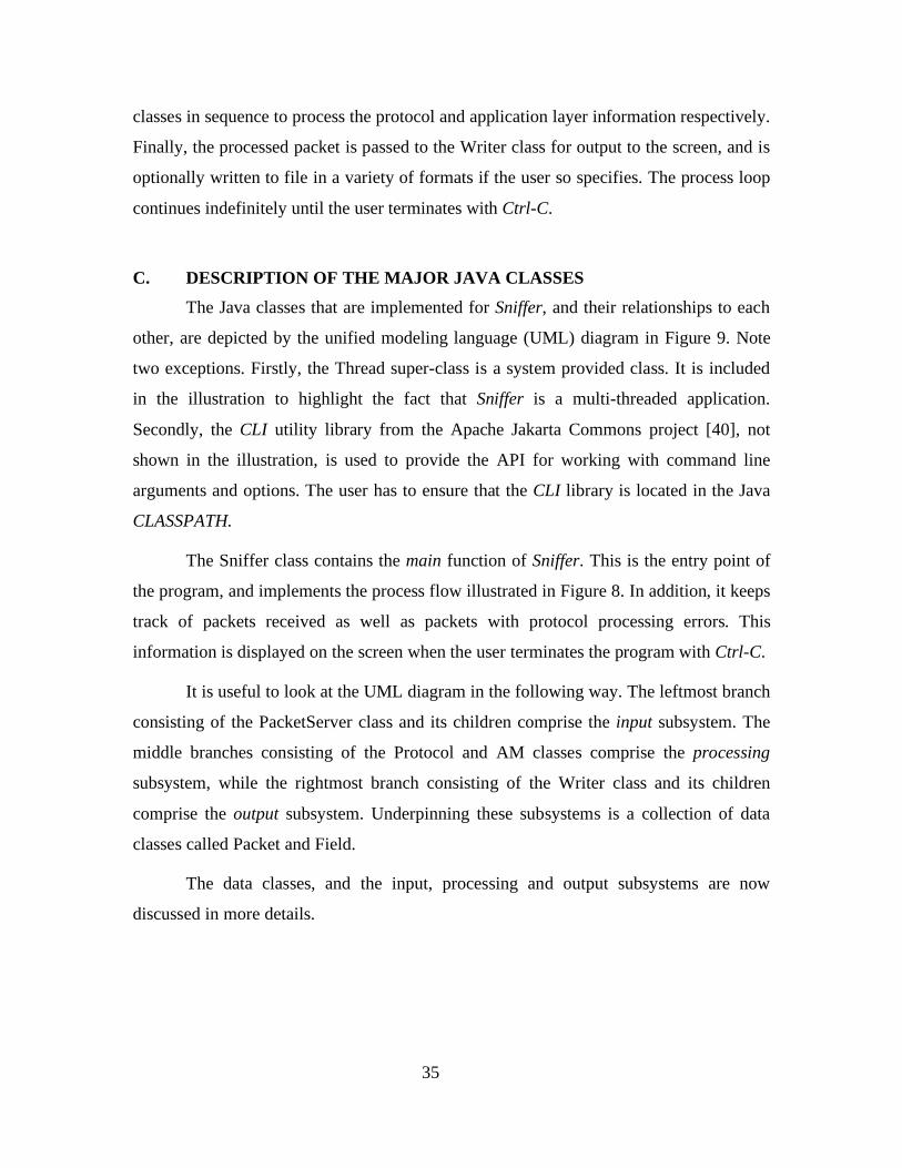
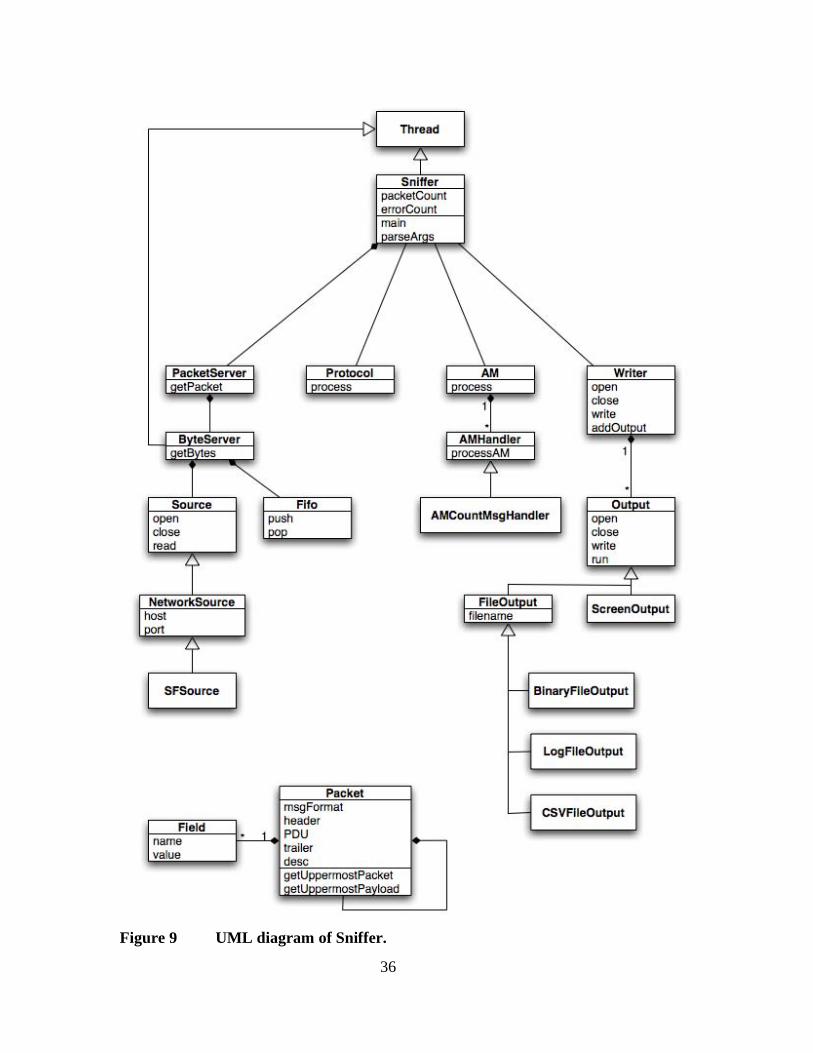
C. DESCRIPTION OF THE MAJOR JAVA CLASSES The Java classes that are implemented for Sniffer, and their relationships to each
other, are depicted by the unified modeling language (UML) diagram in Figure 9. Note
two exceptions. Firstly, the Thread super-class is a system provided class. It is included
in the illustration to highlight the fact that Sniffer is a multi-threaded application.
Secondly, the CLI utility library from the Apache Jakarta Commons project [40], not
shown in the illustration, is used to provide the API for working with command line
arguments and options. The user has to ensure that the CLI library is located in the Java
CLASSPATH.
The Sniffer class contains the main function of Sniffer. This is the entry point of
the program, and implements the process flow illustrated in Figure 8. In addition, it keeps
track of packets received as well as packets with protocol processing errors. This
information is displayed on the screen when the user terminates the program with Ctrl-C.
It is useful to look at the UML diagram in the following way. The leftmost branch
consisting of the PacketServer class and its children comprise the input subsystem. The
middle branches consisting of the Protocol and AM classes comprise the processing
subsystem, while the rightmost branch consisting of the Writer class and its children
comprise the output subsystem. Underpinning these subsystems is a collection of data
classes called Packet and Field.
The data classes, and the input, processing and output subsystems are now
discussed in more details.
36
Figure 9 UML diagram of Sniffer.
37
1. Data Classes In order to capture the representation of a packet accurately as it is processed
through the program, Sniffer defines a Field class and a Packet class. A Field is simply
some value with an associated name. A Packet is represented as a triplet of header,
payload data unit (PDU), and trailer. It may also have a description string. The
description is useful for displaying human-readable packet information on the screen.
The header and trailer are defined as linked lists of Fields. Perhaps more
intriguingly, the PDU is itself defined as a Packet. The Packet class is therefore a nested
class. This allows packets to be encapsulated inside another packet easily.
If the PDU is null, then this Packet is the uppermost packet, and all the
information about the packet is stored in the header. In OSI parlance, an upper layer
payload is encapsulated inside a lower layer protocol. So uppermost, in this case, means
the higher layer payload. The current processing system should only concern itself with
the uppermost packet and payload.
In this case, there are two possibilities. On one hand, the header list may consist
of just a single field containing the data payload waiting to be processed. On the other
hand, the header can be null, indicating that there is no more data to be process, i.e. this
packet has been fully resolved.
Hence, packet protocol processing works as follows:
1) Use the getUppermostPacket method to get the uppermost packet.
2) Use the getUppermostPayload method to get the uppermost payload to be
processed.
3) Process the payload accordingly to derive new header, trailer and PDU
information.
4) Replace the uppermost packet's header, PDU and trailer attributes with the new
information. The new PDU will now become the new uppermost packet to the
next protocol layer.

38
2. Input Subsystem The heart of the input subsystem is the ByteServer class. A ByteServer object is
instantiated by PacketServer, when it is in turn instantiated by the Sniffer class.
ByteServer is a separate thread of execution from the main Sniffer class. This allows
input from the sniffer mote to be received in the most responsive way, independent from
the execution of the rest of the program.
The ByteServer receives data from the sniffer mote through objects subclassed
from the Source class. Currently, only the SFSource (or Serial Forwarder Source) class is
implemented. However, it is perfectly possible to implement other sources if necessary,
for example a SerialSource class that communicates with the mote directly via serial port
communications, or a file source to read data previously archived in a file. It shall be seen
later that additional sources can be easily created and added to the system. By default,
Serial Forwarder is assumed to be running on the local host, port 9001. If this is not the
case, then the user can specify a host and port using the “-h” and “-p” options.
Data read from the source is stored in a First-In-First-Out (FIFO) buffer. In the
current implementation, when the buffer is full, further packet data are dropped, instead
of overriding the earliest received data.
The Sniffer class does not talk to the ByteServer directly, instead it instantiates
and requests packets from the PacketServer class. PacketServer provides a packet-level
input abstraction to Sniffer. PacketServer makes requests for received data from
ByteServer, and then packages the data bytes into a Packet object as its payload. At the
same time, PacketServer adds a timestamp to this Packet’s header. This timestamp
information allows for temporal analysis of the packets. Strictly speaking, the timestamp
does not represent the time the packet is received by the sniffer mote, but the time
PacketServer receives the data from ByteServer.
3. Processing Subsystem Packet objects received from the input subsystem are passed to the processing
subsystem, to extract protocol and application layer information. Packet objects are
passed to the Protocol class and then the AM class in sequence.
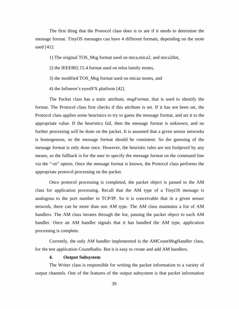
39
The first thing that the Protocol class does is to see if it needs to determine the
message format. TinyOS messages can have 4 different formats, depending on the mote
used [41]:
1) The original TOS_Msg format used on mica,mica2, and mica2dot,
2) the IEEE802.15.4 format used on telos family motes,
3) the modified TOS_Msg format used on micaz motes, and
4) the Infineon’s eyesIFX platform [42].
The Packet class has a static attribute, msgFormat, that is used to identify the
format. The Protocol class first checks if this attribute is set. If it has not been set, the
Protocol class applies some heuristics to try to guess the message format, and set it to the
appropriate value. If the heuristics fail, then the message format is unknown, and no
further processing will be done on the packet. It is assumed that a given sensor networks
is homogenous, so the message format should be consistent. So the guessing of the
message format is only done once. However, the heuristic rules are not foolproof by any
means, so the fallback is for the user to specify the message format on the command line
via the “-m” option. Once the message format is known, the Protocol class performs the
appropriate protocol processing on the packet.
Once protocol processing is completed, the packet object is passed to the AM
class for application processing. Recall that the AM type of a TinyOS message is
analogous to the port number in TCP/IP. So it is conceivable that in a given sensor
network, there can be more than one AM type. The AM class maintains a list of AM
handlers. The AM class iterates through the list, passing the packet object to each AM
handler. Once an AM handler signals that it has handled the AM type, application
processing is complete.
Currently, the only AM handler implemented is the AMCountMsgHandler class,
for the test application CountRadio. But it is easy to create and add AM handlers.
4. Output Subsystem The Writer class is responsible for writing the packet information to a variety of
output channels. One of the features of the output subsystem is that packet information
40
can be written to more than one channel simultaneously. Thus the user has the maximum
flexibility in storing packet information.
The Writer class maintains a list of Output objects. The ScreenOutput object is
always available. At the same time, the user can choose to enable other output channels
using command line options. Currently, the following FileOutput objects are available:
logging the screen output to file (“-l”), writing to a binary file (“-ob”), and writing to a
comma separated value (CSV) file (“-oc”). The CSV file, for example, is readily
imported into Microsoft Excel for data analysis purposes. The binary file, on the other
hand, provides a more efficient format to store packet information.
When an Output object is instantiated, its run method is also immediately
registered with the JVM runtime as a shutdown hook. This is a little known feature of
Java that was recently added to allow programs to perform last minute clean-ups before
JVM termination. In this case, the shutdown hooks enable the ScreenOutput object to
print out packet accounting information, and the FileOutput objects to flush their I/O
buffers and close the file properly.
Again, if a particular output channel is not available, it can be easily created and
added to the system.
D. EXTENDING SNIFFER The Sniffer program has been designed so that it is easy to create and add
functionalities to the various subsystem, without affecting how the rest of the system
works. Part of the reason for this capability lies in the object oriented nature of Java. In
general, adding functionality to Sniffer can be done in two steps: subclassing an existing
class, then making the new class known to the Sniffer at the appropriate code locations.
1. Adding Input Sources New input sources should subclass the Source class, or any of its subclasses, and
override the open, close, and read methods where necessary.
Within the main Sniffer class, a new command line option may be specified so
that the user can choose this input source instead of the default SFSource. Then inside the
code that checks for this option in parseArgs, the new Source object must be instantiated,
41
and assigned it to the source static variable. ByteServer will automatically interface with
the new input source.
2. Adding AM Handlers Handlers for new AM types should subclass the AMHandler class, and override
the processAM method.
The new AM handler class must then register with the AM class within the
following code static segment of AM.java: /* * Static code block. * This is where new AM handlers are registered. */ static {
appsList.add(new AMCountMsgHandler ()); // Add new AM handlers here, like above.
} 3. Adding output channels New output channels should subclass the Output class, and override the open,
close, write, and run methods where necessary.
Similar to the input subsystem, within the main Sniffer class, a new command line
option may be specified so that the user can choose to enable this new output channel.
Then inside the code that checks for this option in parseArgs, the new Output object must
be instantiated, and added to Writer’s list of Output objects using the addOutput method.
Packet information will then be automatically written to the output channel.
E. TEST AND EVALUATION The sniffing functionality of the TinyOS sniffer was tested and evaluated using a
simple test application. For the purpose of this study, the target sensor network is a pair
of MicaZ motes running the CountRadio application. The sniffer consists of a TelosB
mote connected to a PC.
For convenience, it was assumed that the operating radio channel was known. It is
not difficult to find out anyway – a simple sequential scan through the radio frequency
channels, or a spectrum analyzer, will easily reveal the operating radio channel.

42
1. CountRadio application CountRadio is an example application that can be found under the tinyos/apps/
directory. From its README.CountRadio file:
“CountRadio is a simple led/radio count program. The default application built from this directory is CountDual. CountDual either sends a count over the radio if the node address is equal to 1, or displays a count received over the radio otherwise.”
The transmitting mote broadcasts a packet every 200 milliseconds, or five packets
per second. The payload of the packet has the format defined in the CountMsg.h file: enum { AM_COUNT_MSG = 4, }; typedef struct { uint16_t n; uint16_t src; } CountMsg_t;
Hence the payload is of constant four byte length, where the first two bytes
represent a monotonically increasing sequence number, followed by a constant source
address which should be 1. Therefore, this provides a very predictable data source to
verify the correctness of our Sniffer program.
2. Output With the motes up and running, Sniffer is started from the command line with no
additional options. Figure 10 shows the captured screen output of Sniffer. Each line
represents one packet. The format of the output is designed to mimic tcpdump to a certain
extent. It has the following form:
<Timestamp> <Protocol> <Grp>.<Dest>.<AM> (<Len>) [<Payload>] <CRC>
The timestamp is in the 24-hour notation, with up to millisecond precision. The
protocol is denoted as “TOS”, meaning TinyOS with TinySec disabled. The group ID,
destination address and AM types are grouped into a “dotted” decimal notation that
resembles an IP address with its port number.

43
Then using the CSV file output of Sniffer, and importing into Excel, it can be
further verified that the sequence number N runs in consecutive order, so no packets were
missed.
Figure 10 Captured screen output of Sniffer sniffing on 2 motes running the CountRadio application. The sniffer was started after the motes. Hence the lower packet count.

44
3. Observations and Recommendations While it would appear that the Sniffer is functioning correctly, the following
observations are made.
Timestamp: The first observation is that the intervals between sequential
packets are not exactly 200 milliseconds, give or take some acceptable deviations. In fact,
just from the snapshot shown in Figure 10 alone, the interval can be as short as four
milliseconds, to as large as 400 milliseconds. In a network where the data rate is on the
order of tens to hundreds of kilobits per second, an error of 400 milliseconds may be
enough to skew certain traffic analysis.
The inaccuracy of the timestamp is mainly due to the fact that the sniffer mote
does not currently have the ability to affix timestamps to sniffed packets as it receives
them. Instead, the timestamp is only added at the PacketServer level. The fact that the
Source object is a network interface, while convenient from programming point of view,
inevitably adds further errors to the timestamp. There is clearly room for improvement.
CRC: The second, and more important, observation is that CRC information is
missing. Unfortunately, the point along the TinyOS chain where the CRC information is
lost could not be determined. But it does point out that the current implementation is
incomplete, since it cannot provide the packet in its entirety for analysis.
To address these deficiencies, the Sniffer program should be more tightly
integrated with the mote hardware. One possibility is to implement a Source object that
interfaces with the mote directly via the serial link without any mediation. In this way,
the Source object can also be responsible to affix a timestamp on the received packets for
a higher degree of accuracy in the timestamp.
F. SUMMARY The design and implementation of the Sniffer program has been described in
detail, including its usage, process flow, and the functions of the major Java classes. It
has also been explained how new input sources, application handlers, and output channels
can be easily created and added to the program in a very modular way.

45
The testing of the Sniffer program indicates that there are deficiencies in its
implementation: firstly, the timestamp has too much deviation. Secondly, the Sniffer does
not have access to the sniffed packet in its entirety. A tighter integration of the Sniffer
program and the mote hardware should be able to address these deficiencies.

46
THIS PAGE INTENTIONALLY LEFT BLANK

47
VII. CONCLUSION
TinyOS and IEEE 802.15.4 are the two dominant implementations of sensor
networks today. TinyOS targets devices where energy and computational power are the
significant resource constraints. 802.15.4 takes a more modular approach to its design,
and is suited for a variety of devices and applications. Currently TinyOS is more popular
in the sensor network community, but that is probably because it has been around longer.
With 802.15.4 being formally adopted as a standard recently, it should not be long before
802.15.4 starts to take root in the sensor network community.
This thesis examined the security architectures of TinyOS and 802.15.4. It found
that 802.15.4 generally offers higher assurances in terms of cryptographic strength,
message integrity, and information leakage from IV reuse. TinyOS applications will need
robust re-keying support and countermeasures against forgery attempts to make up the
difference. But they both lack effective peer-level access control and replay protection –
both important aspects of sensor network security.
For resource-limited sensor networks, TinyOS is still the better choice. For
military applications where security and performance needs dominate, it is envisioned
that a hybrid TinyOS/802.15.4 system would be ideal. Given the open source nature of
the TinyOS project, it is conceivable that TinyOS can be adapted to leverage on
802.15.4-compliant hardware for its link layer security, instead of relying on TinySec.
TinyOS packets can be encapsulated inside 802.15.4 frames, just like TCP/IP packets are
encapsulated inside 802.11 frames. In this way, sensor network applications can be built
that enjoy the best of both worlds – the mature and optimized environment of TinyOS,
and the superior link layer security offered by 802.15.4.
As a tool for validating the above security analysis and also to perform further
analysis, the design and implementation of a TinyOS sniffer application was presented. A
sniffer is the quintessential tool for modern day network analysis. But such a tool is
presently lacking in today’s sensor network development kits. The current design is based
on existing sensor network hardware and software components to enable a low-cost
48
sniffer implementation. The sniffer has also been designed to be easily extensible in
terms of functionalities.
The following topics are the recommended for further research:
• Improve the functionality of the TinyOS sniffer. Areas of improvement
include tighter integration of the Sniffer with the mote hardware, and
additional output modes for packet data such as the extensible markup
language (XML) format.
• Integrate TinyOS with 802.15.4-compliant hardware for high assurance
applications, with support for peer-level access control and replay protection.
49
LIST OF REFERENCES
1. Chee-Yee Chong and Srikanta P. Kumar. “Sensor Networks: Evolution, Opportunities and Challenges.” Proceedings of the IEEE, vol. 91, issue 8, pp. 1247-1256, Aug. 2003.
2. Adrian Perrig, John Stankovic, and David Wagner. “Security in Wireless Sensor Networks.” Communications of the ACM, vol. 47, issue 6, pp. 53-57, Jun. 2004.
3. Haowen Chen and Adrian Perrig. “Security and Privacy in Sensor Networks.” IEEE Computer, pp. 103-105, Oct. 2003.
4. Anthony Wood and John Stankovic. “Denial of Service in Sensor Networks.” IEEE Computer, pp. 48-56, Oct. 2002.
5. Chris Karlof and David Wagner. “Secure Routing in Wireless Sensor Networks: Attacks and Countermeasures.” In First IEEE International Workshop on Sensor Network Protocols and Applications (IEEE SPNA), pp. 113-127, May 2003.
6. John Douceur. “The Sybil Attack.” In Proc. of the IPTPS02 Workshop, pp. 251-260. Cambridge, MA, USA. Mar. 2002.
7. James Newsome, Elain Shi, Dawn Song, and Adrian Perrig. “The Sybil Attack in Sensor Networks: Analysis and Defenses.” In Information Processing in Sensor Networks (IPSN’04), pp. 259-268. Berkeley, CA. Apr. 2004.
8. (Jan. 2004), “CC2420 Packet Sniffer.” Chipcon AS, Oslo, Norway. [Online]. Available: http://www.chipcon.com/index.cfm?dok_id=129&kat_id=6
9. Naveen Sastry and David Wagner. “Security Considerations for IEEE 802.15.4 Networks.” Presented at the ACM Workshop on Wireless Security 2004 (WiSE’04), pp. 32-42. Philadelphia, Penn., USA. Oct. 1, 2004.
10. Adrian Perrig, Robert Szewczyk, Victor Wen, David Culler, and J.D. Tygar. “SPINS: Security Protocols for Sensor Networks.” Wireless Networks, vol. 8, issue 5, pp. 521-534. Sep. 2002.
11. “Part 15.4: Wireless Medium Access Control (MAC) and Physical Layer (PHY) Specifications for Low-Rate Wireless Personal Area Networks (LR-WPANs).” IEEE Standard 802.15.4-2003. May 2003.
12. Pete Cross. “Zeroing on Zigbee Part 1,” Circuit Cellar, issue 175, pp. 16-23. Feb. 2005.
13. Zigbee Alliance. http://www.zigbee.org. Last accessed May 2006. 14. “Information technology - Open Systems Interconnection - Basic Reference
Model: The basic model.” ITU-T Recommendation X.200. Jul. 1994. 15. Daniel Barrett and Richard Silverman. SSH, The Secure Shell : The Definitive
Guide, 2nd ed. O'Reilly Media, Inc. May 2005. 16. The TLS Protocol, Version 1.0. RFC 2246. Jan. 1999.

50
17. Security Architecture for the Internet Protocol. RFC 2401. Nov. 1998. 18. William Stallings. Network Security Essentials, Applications and Standards, 2nd
ed. Prentice Hall. 2003. 19. Jean-Francois Raymond. “Traffic Analysis: Protocols, Attacks, Design Issues and
Open Problems.” In Designing Privacy Enhancing Technologies: Proceedings of International Workshop on Design Issues in Anonymity and Unobservability, pp. 10-29. 2001.
20. Chris Karlof, Naveen Sastry, and David Wagner. “TinySec: A Link Layer Security Architecture for Wireless Sensor Networks.” In Second ACM Conference on Embedded Networked Sensor Systems, pp. 162-175. Baltimore, Maryland, USA. Nov. 2004.
21. “Security Architecture for Open Systems Interconnection for CCITT Applications – Annex D Layer Two Security Service and Mechanisms for LAN.” ITU-T Recommendation X.800 Amendment 1. Oct. 1996.
22. Bruce Schneier. Applied Cryptography, 2nd ed. Wiley. 1996. 23. “Federal Information Processing Standards Publication 197: Advanced
Encryption Standard (AES).” National Institute of Standards and Technologies (NIST), FIPS PUB 197. Nov. 26, 2001.
24. D. Whiting, R.Housley, and N. Ferguson. Counter with CBC-MAC (CCM). RFC 3610. Sep. 2003.
25. M. Bellare, A. Desai, E. Jokipii, and P. Rogaway. “A Concrete Security Treatment of Symmetric Encryption: Analysis of the DES Modes of Operation.” in Proceedings of the 38th Annual Symposium on Foundations of Computer Science (FOCS 97), New York, USA. 1997.
26. E. Dawson and L. Nielsen. “Automated cryptanalysis of XOR plaintext strings.” Cryptologia, vol 2, pp. 165-181. Apr. 1996.
27. Crossbow Technology. Inc., http://www.xbow.com. Last accessed May 2006. 28. TinyOS. http://www.tinyos.net. Last accessed May 2006.
29. David Gay, Philip Levis, Robert von Behren, Matt Welsh, Eric Brewer, and David Culler. “The nesC language: A holistic approach to networked embedded systems.” In ACM SIGPLAN Conference on Programming Language Design and Implementation, pp. 1-11. 2003.
30. (Sep. 2005) “Getting Started Guide, Rev. A, Sep. 2005, Document 7430-0022-07.” Crossbow Technology, Inc., San Jose, CA., USA. [Online]. Available: http://www.xbow.com/Support/Support_pdf_files/Getting_Started_Guide.pdf
31. “Part 11: Wireless LAN Medium Access Control (MAC) and Physical Layer (PHY) Specifications.” ANSI/IEEE Std 802.11. 1999.
32. Jon Edney and William Arbaugh. Real 802.11 Security: Wifi Protected Access and 802.11i. Addison-Wesley. 2004.
51
33. (Oct. 2005) “SmartRF® CC2420 Datasheet (rev 1.3), 2005-10-03.” Chipcon AS, Norway. [Online]. Available: http://www.chipcon.com/files/CC2420_Data_Sheet_1_3.pdf
34. “Mica2 data sheet.” Crossbow Technology, Inc., San Jose, CA., USA. [Online]. Available: http://www.xbow.com/Products/Product_pdf_files/Wireless_pdf/MICA2_Datasheet.pdf
35. “MicaZ data sheet,” Crossbow Technology, Inc., San Jose, CA., USA. [Online]. Available: http://www.xbow.com/Products/Product_pdf_files/Wireless_pdf/MICAZ_Datasheet.pdf
36. (Mar. 29, 2004) “New MAC Address Spoofing Tool for Linux (SirMACsAlot).” Defcon Forums, General Area, Wireless Technology. [Online]. Available: http://forum.defcon.org/showthread.php?t=3541
37. Nikita Borisov, Ian Goldberg, and David Wagner. “Intercepting mobile communications: The insecurity of 802.11.” In The Seventh Annual International Conference on Mobile Computing and Networking (MOBICOM 2001), pp. 180-189. 2001.
38. (Jun. 17, 2004) Chris Karlof, Naveen Sastry, and David Wagner. “TinySec: User Manual.” [Online]. Available: http://www.cs.berkeley.edu/~nks/tinysec/TinySec-userguide.pdf.
39. tcpdump/libpcap. http://www.tcpdump.org. Last accessed May 2006.
40. The Apache Jakarta Project, Commons CLI. http://jakarta.apache.org/commons/cli. Last accessed May 2006.
41. (Mar. 25, 2005) Gilman Tolle. “Serial Forwarder Protocol” [Online]. Available: http://cents.cs.berkeley.edu/tinywiki/index.php/Serial_Forwarder_Protocol
42. (Jan. 30, 2006) “eyesIFX Sensor Network Development Kit- Documentation (Version 1.0.2)” Infineon Technologies AG, Germany. [Online]. Available: http://www.infineon.com/upload/Document/Eyes2.1_Doc_102.pdf

52
THIS PAGE IS INTENTIONALLY LFFT BLANK

53
INITIAL DISTRIBUTION LIST
1. Defense Technical Information Center
Ft. Belvoir, Virginia
2. Dudley Knox Library Naval Postgraduate School Monterey, California
3. John McEachen Department of Electrical and Computer Engineering Naval Postgraduate School Monterey, California
4. Weilian Su Department of Electrical and Computer Engineering Naval Postgraduate School Monterey, California
5. Temasek Defence Systems Institute
National University of Singapore Singapore