naval postgraduate · pdf fileuntil approximately 1970, radio frequency ... the past three...
TRANSCRIPT

NAVAL
POSTGRADUATE SCHOOL
MONTEREY, CALIFORNIA
THESIS
ELECTROMAGNETIC COMPATIBILITY (EMC) REQUIREMENTS FOR MILITARY AND COMMERCIAL
EQUIPMENT
by
James D. Pierce Jr.
September 2009
Thesis Advisor: Rachel E. Goshorn Second Reader: Neal K. Stetson
Approved for public release; distribution is unlimited
i
REPORT DOCUMENTATION PAGE Form Approved OMB No. 0704-0188 Public reporting burden for this collection of information is estimated to average 1 hour per response, including the time for reviewing instruction, searching existing data sources, gathering and maintaining the data needed, and completing and reviewing the collection of information. Send comments regarding this burden estimate or any other aspect of this collection of information, including suggestions for reducing this burden, to Washington headquarters Services, Directorate for Information Operations and Reports, 1215 Jefferson Davis Highway, Suite 1204, Arlington, VA 22202-4302, and to the Office of Management and Budget, Paperwork Reduction Project (0704-0188) Washington DC 20503.
1. AGENCY USE ONLY (Leave blank)
2. REPORT DATE September 2009
3. REPORT TYPE AND DATES COVERED Master’s Thesis
4. TITLE AND SUBTITLE Electromagnetic Compatibility (EMC) Requirements for Military and Commercial Equipment
6. AUTHOR(S) Pierce, James D. Jr.
5. FUNDING NUMBERS
7. PERFORMING ORGANIZATION NAME(S) AND ADDRESS(ES) Naval Postgraduate School Monterey, CA 93943-5000
8. PERFORMING ORGANIZATION REPORT NUMBER
9. SPONSORING /MONITORING AGENCY NAME(S) AND ADDRESS(ES) N/A
10. SPONSORING/MONITORING AGENCY REPORT NUMBER
11. SUPPLEMENTARY NOTES The views expressed in this thesis are those of the author and do not reflect the official policy or position of the Department of Defense or the U.S. Government.
12a. DISTRIBUTION / AVAILABILITY STATEMENT Approved for public release; distribution is unlimited
12b. DISTRIBUTION CODE A
13. ABSTRACT (maximum 200 words)
Until approximately 1970, radio frequency (RF) requirements were driven by military usage, and electromagnetic compatibility (EMC) efforts were conducted by the military and a few select industries. This was largely due to the fact that limited applications and high costs had kept the use of consumer electronics to a minimum.
The past three decades, however, have seen a fundamental shift in this status quo. Starting with the emergence of the microprocessor in the mid-70s, commercial applications began to take the lead of technology development and the consumer market has grown exponentially.
Widespread use of electronics in both the military and private sectors has impacted the available use of the RF spectrum. As the demands for “connectivity” continue to grow, wireless capabilities are competing for the bandwidth necessary to handle the expanding flow of information society has come to expect. As consumer usage has come to drive electronic development, the military also finds itself in the position of adopting and adapting commercial technology.
This study examines the origins of the military and commercial requirements that regulate EMC, evaluates the adequacy of these requirements with respect to current spectrum demands, and investigates the potential for harmonizing military and commercial EMC assessments.
15. NUMBER OF PAGES
93
14. SUBJECT TERMS Electromagnetic, interference, compatibility, EMC, EMI, spectrum, RF, frequency, COTS, MIL-STD-461, MIL-STD-464, vulnerability, electric field, radiated emissions, radiated susceptibility, radiated immunity, CFR 47, Part 15.
16. PRICE CODE
17. SECURITY CLASSIFICATION OF REPORT
Unclassified
18. SECURITY CLASSIFICATION OF THIS PAGE
Unclassified
19. SECURITY CLASSIFICATION OF ABSTRACT
Unclassified
20. LIMITATION OF ABSTRACT
UU
NSN 7540-01-280-5500 Standard Form 298 (Rev. 2-89) Prescribed by ANSI Std. 239-18

ii
THIS PAGE INTENTIONALLY LEFT BLANK
iii
Approved for public release; distribution is unlimited
ELECTROMAGNETIC COMPATIBILITY (EMC) REQUIREMENTS FOR MILITARY AND COMMERCIAL EQUIPMENT
James D. Pierce Jr.
Civilian, Naval Sea Systems Command B.F.A., University of Tennessee, 1987
B.S., Tennessee Technological University, 1997
Submitted in partial fulfillment of the requirements for the degree of
MASTER OF SCIENCE IN SYSTEMS ENGINEERING MANAGEMENT
from the
NAVAL POSTGRADUATE SCHOOL September 2009
Author: James D. Pierce Jr.
Approved by: Rachel E. Goshorn Thesis Advisor
Neal K. Stetson Second Reader
David Olwell Chairman, Department of Systems Engineering

iv
THIS PAGE INTENTIONALLY LEFT BLANK
v
ABSTRACT
Until approximately 1970, radio frequency (RF) requirements were driven by
military usage, and electromagnetic compatibility (EMC) efforts were conducted by the
military and a few select industries. This was largely due to the fact that limited
applications and high costs had kept the use of consumer electronics to a minimum.
The past three decades, however, have seen a fundamental shift in this status quo.
Starting with the emergence of the microprocessor in the mid-70s, commercial
applications began to take the lead of technology development, and the consumer market
has grown exponentially.
Widespread use of electronics in both the military and private sectors has
impacted the available use of the RF spectrum. As the demands for “connectivity”
continue to grow, wireless capabilities are competing for the bandwidth necessary to
handle the expanding flow of information society has come to expect. As consumer
usage has come to drive electronic development, the military also finds itself in the
position of adopting and adapting commercial technology.
This study examines the origins of the military and commercial requirements that
regulate EMC, evaluates the adequacy of these requirements with respect to current
spectrum demands, and investigates the potential for harmonizing military and
commercial EMC assessments.

vi
THIS PAGE INTENTIONALLY LEFT BLANK

vii
TABLE OF CONTENTS
I. INTRODUCTION........................................................................................................1 A. BACKGROUND ..............................................................................................1 B. PURPOSE.........................................................................................................2 C. RESEARCH QUESTIONS.............................................................................3 D. BENEFITS OF STUDY...................................................................................3 E. SCOPE ..............................................................................................................4 F. METHODOLOGY ..........................................................................................4 G. THESIS OVERVIEW .....................................................................................4
II. EMI OVERVIEW........................................................................................................7 A. ELECTROMAGNETIC RADIATION .........................................................7 B. RADIO WAVES...............................................................................................9 C. ELECTROMAGNETIC INTERFERENCE...............................................10 D. EMC TESTING .............................................................................................12
III. INITIAL DEVELOPMENT OF RF TECHNOLOGIES (1900–1969) ................15 A. BACKGROUND ............................................................................................15 B. MILITARY ADVANCEMENTS .................................................................15 C. COMMERCIAL USE....................................................................................17 D. EARLY EMC REGULATION.....................................................................20
IV. MICROPROCESSORS AND CONSUMER DEMAND (1970–2009) .................23 A. BACKGROUND ............................................................................................23 B. EMITTERS IN HOMES ...............................................................................24 C. PERSONAL COMPUTING .........................................................................25 D. WIRELESS TELEPHONY ..........................................................................25 E. SATELLITE TELEVISION & RADIO ......................................................26 F. WIRELESS STANDARDS ...........................................................................27 G. MILITARY.....................................................................................................29 H. MILITARY USE OF COTS .........................................................................35
V. MILITARY EMC GUIDELINES ............................................................................37 A. DOD SPECTRUM REGULATION.............................................................37 B. MILITARY EMC REQUIREMENTS ........................................................38
1. Overview .............................................................................................38 2. MIL-STD-461 .....................................................................................39 3. MIL-STD-464 .....................................................................................43
VI. COMMERCIAL EMC GUIDELINES....................................................................47 A. COMMERCIAL EMI REGULATION .......................................................47 B. EUROPE.........................................................................................................47 C. UNITED STATES..........................................................................................49
1. Overview .............................................................................................49 2. CFR 47, Part 15..................................................................................50 3. CFR 47, Part 18..................................................................................51
viii
4. CFR 47, Part 95..................................................................................52 5. ANSI C63.12 .......................................................................................52
VII. ALIGNMENT OF EMC REQUIREMENTS..........................................................53 A. COMPARISON OF MILITARY AND COMMERCIAL
STANDARDS .................................................................................................53 1. Overview .............................................................................................53 2. RE101: Radiated Emissions–Magnetic Field .................................54 3. RE102: Radiated Emissions–Electric Field....................................54 4. RS101: Radiated Susceptibility–Magnetic Field............................55 5. RS103: Radiated Susceptibility–Electric Field ..............................55 6. Summary.............................................................................................56
B. COMPARISON OF COMMERCIAL STANDARDS AND USAGE .......57 C. COMPETING FOR RESOURCES .............................................................59
VIII. CONCLUSIONS ........................................................................................................61 A. SUMMARY ....................................................................................................61 B. KEY POINTS AND RECOMMENDATIONS ...........................................62 C. AREAS FOR FUTURE EFFORT................................................................63 D. FINAL THOUGHTS .....................................................................................64
LIST OF REFERENCES......................................................................................................65
INITIAL DISTRIBUTION LIST .........................................................................................69

ix
LIST OF FIGURES
Figure 1. Electromagnetic Wave .......................................................................................7 Figure 2. Electromagnetic Spectrum [From ShareAlike 3.0]............................................8 Figure 3. SCR 300 Backpack Walkie Talkie ..................................................................16 Figure 4. AM (top) and FM (bottom) Modulated Signals [After 5]................................18 Figure 5. Cathode Ray Tube (CRT) [From ShareAlike 3.0]...........................................19 Figure 6. Spectral Content of a Television Signal...........................................................20 Figure 7. Timeline of Consumer Electronics ..................................................................23 Figure 8. Single Channel Ground and Airborne Radio System (SINCGARS)...............29 Figure 9. SPY-1 Radar Panel ..........................................................................................30 Figure 10. Joint Tactical Radio System (JTRS) ................................................................34 Figure 11. DoD Spectrum Certification Flow Diagram....................................................38 Figure 12. European Union “CE” Compliance Marking ..................................................49 Figure 13. Plot of Commercial Frequency Use Over Time ..............................................58 Figure 14. U.S. RF Frequency Allocations. ......................................................................60 Figure 15. 1999 Ambient EME Levels [From 29] ............................................................64

x
THIS PAGE INTENTIONALLY LEFT BLANK
xi
LIST OF TABLES
Table 1. RF Frequency Bands........................................................................................11 Table 2. Broadcast Frequencies. ....................................................................................17 Table 3. MIL-STD-461F Platform Requirements [After 22] ........................................40 Table 4. MIL-STD-461F, RE102 Platform Requirements [After 22] ...........................42 Table 5. MIL-STD-461F, RS103 Platform Requirements [After 22]............................43 Table 6. MIL-STD-464A External Shipboard Environments [After 23].......................44 Table 7. Internal Shipboard EMEs [After 23]................................................................44 Table 8. External EME for Ground Systems [After 23] ................................................45 Table 9. IEC Generic Radiated Emissions Requirements (Electric Field). ...................48 Table 10. IEC Immunity Requirements. ..........................................................................49 Table 11. CFR Part 15 Emission Limits. .........................................................................51 Table 12. ANSI C63.12 Emission Limits. .......................................................................52 Table 13. ANSI C63.12 Immunity Limits. ......................................................................52 Table 14. Radiated Emissions–Magnetic Field Comparison. ..........................................54 Table 15. Radiated Emissions–Electric Field Comparison..............................................55 Table 16. Radiated Susceptibility–Magnetic Field Comparison. ....................................55 Table 17. Radiated Susceptibility–Electric Field Comparison. .......................................56 Table 18. Radiated Susceptibility–Electric Field Comparison. .......................................57

xii
THIS PAGE INTENTIONALLY LEFT BLANK
xiii
EXECUTIVE SUMMARY
Radio Frequency (RF) energy is of particular interest because 1) it will propagate
over long distances in Earth’s atmosphere and 2) it can be made to carry information by
varying the amplitude, frequency and phase of the RF wave. Because the “ideal”
transmit window naturally exists between approximately 3 MHz–20 GHz, there is
crowding of intentional transmissions competing for space, as well as inadvertent
propagation of unintentional emissions (noise) by both natural and man-made sources.
The dense population of this particularly desirable range of the electromagnetic spectrum
logically leads to interference issues between users.
Electromagnetic Interference (EMI) is a disturbance that interrupts or degrades
the performance of a system due to electromagnetic energy generated by an outside
source. This energy is transferred to the “victim” system by either electromagnetic
radiation or electromagnetic conduction. Radiated EMI occurs when source and victim
are separated by a relatively large distance (i.e., greater than one wavelength). Radiated
EMI can occur at the signal level, where one signal “jams” another, or it can occur at the
hardware level where the RF energy actually induces an unintended current in the system
that adversely impacts its operation. Conflicting transmissions are considered a spectrum
management issue, while the system anomalies resulting from induced current are
referred to as electromagnetic environmental effects (E3). On the simplest level,
electromagnetic compatibility (EMC) can be defined as the absence of these effects.
Unfortunately, it is not always easy to tell when these effects are truly absent as opposed
to undetected.
Until approximately 1970, RF requirements were driven by military usage, and
EMC efforts were conducted by the military and a few select industries. A review of the
available RF technologies prior to 1970 illustrates the fact that the majority of electronics
during this time were developed by and for the military (with the noticeable exceptions of
AM/FM radio and television), largely due to the limited applications and high costs of
this equipment.
xiv
The past three decades, however, have seen a fundamental shift in this status quo.
Starting with the emergence of the microprocessor in the mid-70s, commercial
applications began to take the lead of technology development and the consumer market
has grown exponentially. A review of this changing technology demonstrates just how
far reaching these developments have been. As commercially manufactured electronics
became increasingly widespread, EMI problems moved from the battlefield to the
suburbs. Escalating consumer demand for the latest and greatest gadget also led the
private sector to ultimately outpace Department of Defense (DoD) in the development of
cutting edge technologies.
Although the U.S. military has maintained a considerable edge over other
countries with respect to technological advancement, more and more, this technology is
based on commercial developments as opposed to being developed in DoD labs. DoD
has recognized the fact that commercial-integration provides opportunities for faster and
lower costs in the development of military equipment. Commercial off-the shelf (COTS)
use also provides access to what has become a much larger industrial base. With these
goals in mind, the Secretary of Defense issued a directive in June 1994 requiring the
military to use performance-based requirements in procurements and to apply
commercial specifications and standards whenever possible. Recent U.S. Department of
Defense Procurement Reform policies expand on this guidance by encouraging the use of
COTS equipment as well. Unfortunately, COTS equipment is not necessarily intended to
operate in the harsh EMEs that are characterized by military standards, such as MIL-
STD-461 and MIL-STD-464. Furthermore, a survey of existing commercial technologies
as of 2009 suggests that commercial standards may not provide adequate regulation with
respect to commercial needs, let alone the needs of the military.
Commercial needs, however, appear to be converging, in some respects, with the
needs of military. Although new technologies, such as cognitive radios and dynamic
spectrum access (DSA), might ultimately ease many of the issues related to spectrum
management, these approaches do not address issues related to E3. In order to maximize
battery power and frequency usage, the operational voltages of commercial devices is
getting lower and lower, resulting in a circuit that is more sensitive to the induced current
xv
that results from E3. At the same time, we no longer live in the benign EM environment
of the 1950s, 1980s, or even 2001. The ambient EME is an additive effect that increases
along with the number of devices that create it. Given the exponential increase in
emitting devices, combined with the fact that these same devices are more likely to be
susceptible, we are reaching a point where E3 effects are going to be a greater problem at
the consumer level. Commercial manufacturers will also have to take new measures to
ensure proper functionality of their products.
This thesis will provide an overview of current and developing spectrum
dependent commercial technologies, examine how these technologies align/overlap with
existing military communication and radar systems, and offer a profile of commercial
spectrum usage with respect to frequencies from 2 MHz to 40 GHz. This profile will be
used to evaluate the sufficiency of EMI requirements currently cited in existing
commercial standards with respect to the demands of both modern commercial and
military usage.
Chapter I provides an introduction and overview for the study.
Chapter II defines and elaborates on the physics related to EMI including EM
wave propagation and free-space path loss.
Chapter III provides a history of the military and commercial spectrum-dependent
equipment developed between 1900 and 1969.
Chapter IV examines the effect of the microprocessor on military and commercial
spectrum-dependent equipment that was developed from 1970 through the present.
Chapter V reviews the requirements of the primary U.S. military standards for
EMC: MIL-STD-461F and MIL-STD-464A.
Chapter VI provides an overview of the U.S. and European commercial EMC
standards including: the IEC 61000 series, ANSI C63.12, and CFR 47.
Chapter VII compares and contrasts MIL-STD-461F with the U.S. and European
commercial standards. The commercial standards are then evaluated with respect to the
spectrum requirements of the equipment from Chapters III & IV.

xvi
Chapter VIII summarizes the conclusions of the study to include
recommendations for near-term and future actions.
xvii
LIST OF ACRONYMS AND ABBREVIATIONS
ABCS Army Battle Command System
AM Amplitude Modulation
ANSI American National Standards Institute
B&W Black and White
CB Citizens’ Band
CENELEC Committee for Electrotechnical Standardization
CFR Code of Federal Regulations
CISPR International Special Committee on Radio Interference
COTS Commercial Off-The Shelf
CRT Cathode Ray Tube
DAB Digital Audio Broadcasting
DARS Digital Audio Radio Satellite
DoD Department of Defense
DSA Dynamic Spectrum Access
EHF Extremely High Frequency
EMC Electromagnetic Compatibility
EME Electromagnetic Environment
EMI Electromagnetic Interference
EMR Electromagnetic Radiation
EUT Equipment Under Test
FCC Federal Communications Commission
FM Frequency Modulation
FSPL Free-Space Path Loss
GHz Gigahertz
GIG Global Information Grid
GOTS Government Off-The Shelf
GPS Global Positioning System
HF High Frequency

xviii
Hz Hertz
IC Integrated Circuit
IEC International Electrotechnical Commission
IFF Identification, Friend or Foe
IRAC Interdepartmental Radio Advisory Committee
ISM Industrial, Scientific, and Medical
JFP Joint Frequency Panel
JTIDS Joint Tactical Information Distribution System
JTRS Joint Tactical Radio System
LF Low Frequency
MBWA Mobile Broadband Wireless Access
MCEB Military Communications-Electronics Board
MF Medium Frequency
MHz Megahertz
MILSTAR Military Strategic Tactical Relay
NAVSTAR Navigation Satellite Timing and Ranging
NTIA National Telecommunications and Information Administration
NTSC National Television System Committee
OATS Open-Air Test Site
OSM Office of Spectrum Management
PC Personal Computer
PCS Personal Communication Services
RADAR Radio Detection and Ranging
RF Radio Frequency
RFID Radio Frequency Identification
SHF Super High Frequency
SINCGARS Single Channel Ground and Airborne Radio System
SSN Space Surveillance Network
TCF Technical Construction File
TV Television
xix
UHF Ultra High Frequency
USB Universal Serial Bus
UWB Ultra-WideBand
VHF Very High Frequency
WiMAX Worldwide Interoperability for Microwave Access
WLAN Wireless Local Area Network
WRAN Wireless Regional Area Network
WUSB Wireless USB

xx
THIS PAGE INTENTIONALLY LEFT BLANK

xxi
ACKNOWLEDGMENTS
To Dr. James Meng and Mr. Carl Siel, for the endorsement that opened the door
to this opportunity.
To Mr. Vance Brahosky and Mr. Dave Goldberg for allowing me the schedule
flexibility that made this accomplishment possible.
To Mr. D. Mark Johnson, Mr. Robert Sweeney, and Mr. Jeffery Shuey for the
gracious manner in which they often carried part of my workload in addition to their own.
To Mr. Scott Hoschar for his invaluable insights and knowledge and his
willingness to drop everything to share both.
To Mr. Neal Stetson for his understanding of the material and its history. His
library of information and wealth of personal knowledge were critical to the completion
of this study.
To Dr. Rachael Goshorn for her technical expertise and assistance in working the
system, but most of all for her patience and encouragement.
To my Parents and Sister for understanding that I did not actually drop off the
face of the Earth in spite of all evidence to the contrary.
And finally, to my wife, Karen, who did all of the above and more. Without her,
none of this would have happened.

xxii
THIS PAGE INTENTIONALLY LEFT BLANK
1
I. INTRODUCTION
A. BACKGROUND
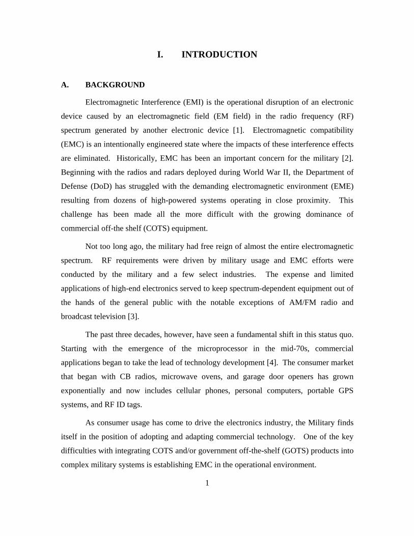
Electromagnetic Interference (EMI) is the operational disruption of an electronic
device caused by an electromagnetic field (EM field) in the radio frequency (RF)
spectrum generated by another electronic device [1]. Electromagnetic compatibility
(EMC) is an intentionally engineered state where the impacts of these interference effects
are eliminated. Historically, EMC has been an important concern for the military [2].
Beginning with the radios and radars deployed during World War II, the Department of
Defense (DoD) has struggled with the demanding electromagnetic environment (EME)
resulting from dozens of high-powered systems operating in close proximity. This
challenge has been made all the more difficult with the growing dominance of
commercial off-the shelf (COTS) equipment.
Not too long ago, the military had free reign of almost the entire electromagnetic
spectrum. RF requirements were driven by military usage and EMC efforts were
conducted by the military and a few select industries. The expense and limited
applications of high-end electronics served to keep spectrum-dependent equipment out of
the hands of the general public with the notable exceptions of AM/FM radio and
broadcast television [3].
The past three decades, however, have seen a fundamental shift in this status quo.
Starting with the emergence of the microprocessor in the mid-70s, commercial
applications began to take the lead of technology development [4]. The consumer market
that began with CB radios, microwave ovens, and garage door openers has grown
exponentially and now includes cellular phones, personal computers, portable GPS
systems, and RF ID tags.
As consumer usage has come to drive the electronics industry, the Military finds
itself in the position of adopting and adapting commercial technology. One of the key
difficulties with integrating COTS and/or government off-the-shelf (GOTS) products into
complex military systems is establishing EMC in the operational environment.

2
Unfortunately, commercial products are not designed to operate in the high-power
EMEs encountered in the military theater of operations. Furthermore, these commercial
systems are not typically tested to the military EMC standards that would provide some
indication of performance and potential vulnerabilities when exposed to these
environments. Meanwhile, there is no comprehensive set of commercial requirements
that covers the entire frequency range utilized in the modern military combat
environment. This lack of empirical data means that system integrators cannot predict
whether a given piece of COTS equipment will function properly or even survive in a
military EME [5].
Of further concern is the possibility that existing commercial standards are
outdated with respect to the demands of the commercial EME. Ten years ago, the
operational frequency for the vast majority of commercial electronics was below 2 GHz.
As such, the requirements of commercial test standards cut off at this point. Today, many
common commercial technologies, such as 802.11 wireless systems, operate above 2
GHz; some technologies, such as WiMAX 802.16 systems, operate at frequencies in
excess of 5 GHz. The commercial test requirements, however, have not been updated to
reflect this expansion. For this reason, the existing commercial EMC standards may not
truly adequate for the needs of the current commercial EME—let alone the needs of the
military combat environment.
B. PURPOSE
This study provides an overview of current and developing spectrum dependent
commercial technologies, examines how these technologies align/overlap with existing
military communication and radar systems, and offers a “composite profile” of
commercial spectrum usage with respect to frequencies from 2 MHz to 40 GHz. This
composite profile forms the basis for an evaluation of the sufficiency of EMI
requirements currently cited in existing commercial standards with respect to the
demands of both modern commercial and military usage. Finally, the thesis examines the
shortfalls and makes recommendations with respect to establishing comprehensive
commercial requirements for radiated susceptibility and radiated emissions based on the
3
actual demands of current commercial technologies. Finally, the thesis will also provide
recommendations for vetting COTS equipment into a harsh military EME.
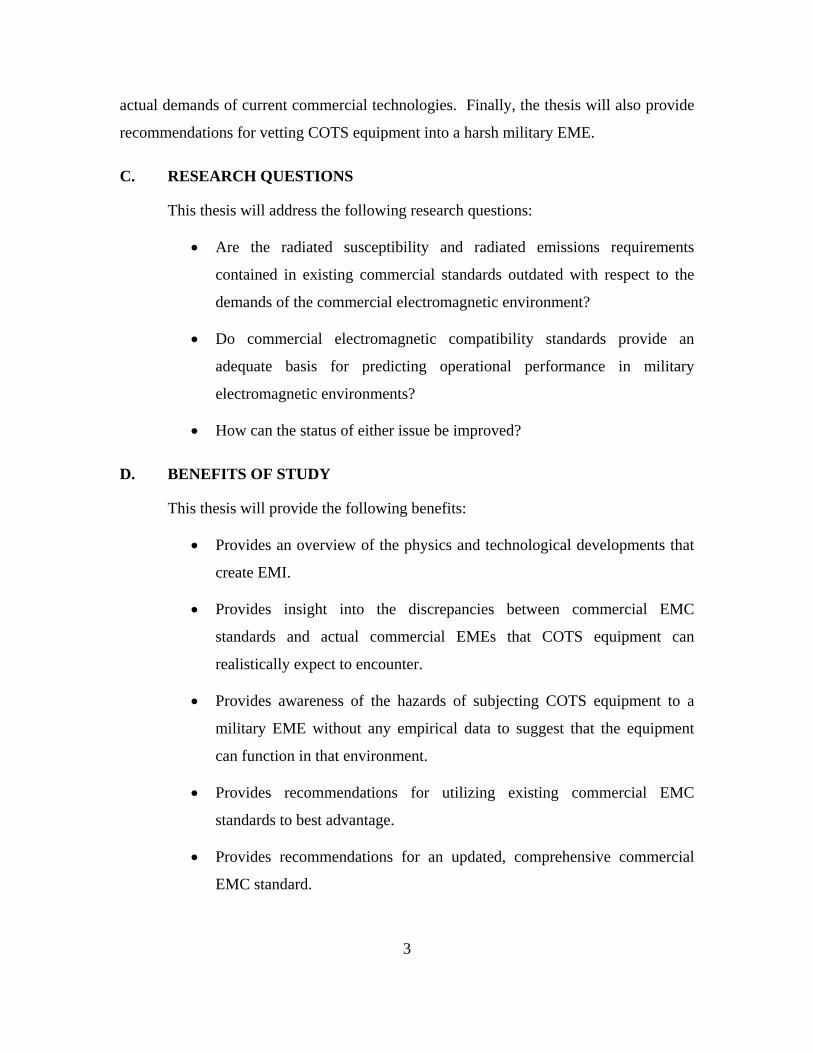
C. RESEARCH QUESTIONS
This thesis will address the following research questions:
Are the radiated susceptibility and radiated emissions requirements
contained in existing commercial standards outdated with respect to the
demands of the commercial electromagnetic environment?
Do commercial electromagnetic compatibility standards provide an
adequate basis for predicting operational performance in military
electromagnetic environments?
How can the status of either issue be improved?
D. BENEFITS OF STUDY
This thesis will provide the following benefits:
Provides an overview of the physics and technological developments that
create EMI.
Provides insight into the discrepancies between commercial EMC
standards and actual commercial EMEs that COTS equipment can
realistically expect to encounter.
Provides awareness of the hazards of subjecting COTS equipment to a
military EME without any empirical data to suggest that the equipment
can function in that environment.
Provides recommendations for utilizing existing commercial EMC
standards to best advantage.
Provides recommendations for an updated, comprehensive commercial
EMC standard.
4
E. SCOPE
The following study focuses on the spectrum usage of actual commercial systems,
both existing and under development that populate the frequency range from 2 MHz to
100 GHz. Based on the collective emissions of these systems, a true profile of modern
commercial spectrum requirements can be derived and compared to the requirements for
radiated emissions and radiated susceptibility contained in existing commercial and
military standards.
F. METHODOLOGY
The thesis methodology is as follows:
1. Conduct literature search and personal interviews for history and
justification of existing EMI requirements.
2. Conduct literature search and personal interviews for current commercial
technologies and their respective spectrum requirements.
3. Develop a comprehensive profile of actual commercial demands on the
electromagnetic spectrum from 2 MHz to 40 GHz.
4. Compare this profile to the corresponding requirements in existing
commercial standards and note any shortfall and/or gaps.
5. Compare the commercial profile to the requirements in existing military
EMI standards and note any shortfalls and/or gaps.
6. Make recommendations for a comprehensive update to existing
commercial EMI test requirements based on discoveries above.
G. THESIS OVERVIEW
Chapter I provides an introduction and overview for the effort.
Chapter II defines and elaborates on the physics related to EMI including EM
wave propagation and free-space path loss.
5
Chapter III provides a history of the military and commercial spectrum-dependent
equipment developed between 1900 and 1969.
Chapter IV examines the effect of the microprocessor on military and commercial
spectrum-dependent equipment that was developed from 1970 through the present.
Chapter V reviews the requirements of the primary U.S. military standards for
EMC: MIL-STD-461F and MIL-STD-464A.
Chapter VI provides an overview of the U.S. and European commercial EMC
standards including: the IEC 61000 series, ANSI C63.12, and CFR 47.
Chapter VII compares and contrasts MIL-STD-461F with the U.S. and European
commercial standards. The commercial standards are then evaluated with respect to the
spectrum requirements of the equipment from Chapters III & IV.
Chapter VIII summarizes the conclusions of the study to include
recommendations for near-term and future actions.

6
THIS PAGE INTENTIONALLY LEFT BLANK
II. EMI OVERVIEW
The following chapter explains the physics of electromagnetic radiation, provides
an overview of radio frequency transmission, and details the fundamental principles of
electromagnetic interference.
A. ELECTROMAGNETIC RADIATION
In order to understand the effects of EMI, it is necessary to first be familiar with
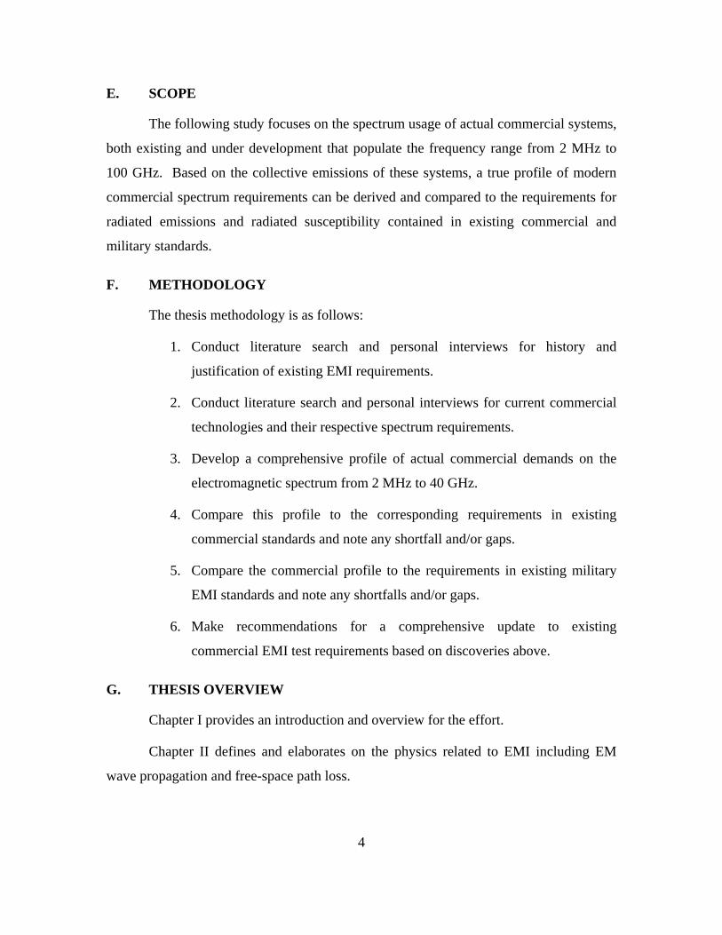
the basic phenomenon of electromagnetic radiation (EMR). EMR is a self-propagating
wave with both an electric field and a magnetic field. These components oscillate in
phase perpendicular to each other and perpendicular to the direction of propagation
(Figure 1). The distance of these oscillations in meters is referred to as wavelength (λ)
and the number of oscillations per second is defined as frequency. In International
System of Units (SI), the standard measure of frequency is hertz (Hz); 1 Hz is equivalent
to one oscillation per second [2].
Figure 1. Electromagnetic Wave
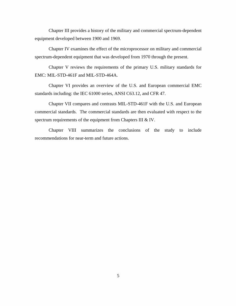
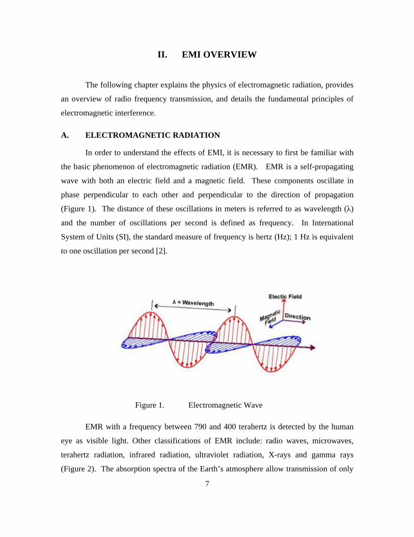
EMR with a frequency between 790 and 400 terahertz is detected by the human
eye as visible light. Other classifications of EMR include: radio waves, microwaves,
terahertz radiation, infrared radiation, ultraviolet radiation, X-rays and gamma rays
(Figure 2). The absorption spectra of the Earth’s atmosphere allow transmission of only
7
certain frequency ranges of EMR. One such “window” allows a portion of the ultraviolet
frequencies, the entire visible spectrum, and most of the infrared band to propagate. A
second window allows the transmission of radio and microwaves. However, the Earth's
atmosphere effectively blocks long-range propagation of terahertz radiation, X-rays and
gamma rays [6].
Figure 2. Electromagnetic Spectrum [From ShareAlike 3.0]
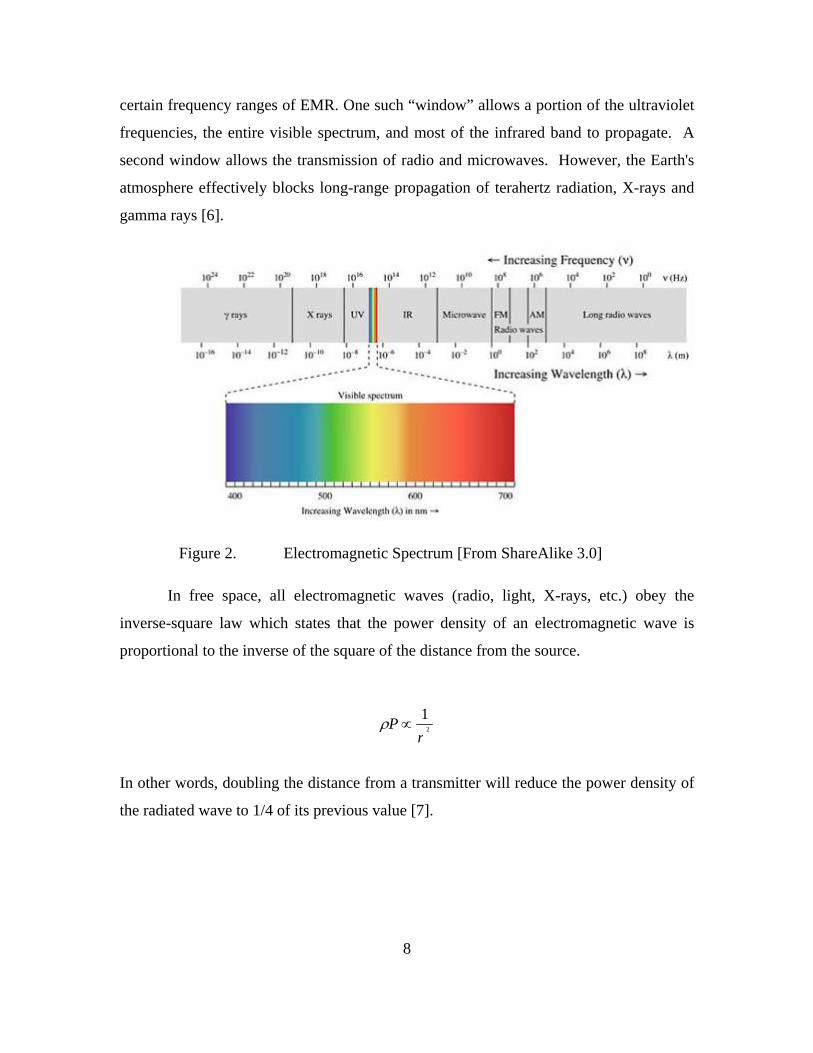
In free space, all electromagnetic waves (radio, light, X-rays, etc.) obey the
inverse-square law which states that the power density of an electromagnetic wave is
proportional to the inverse of the square of the distance from the source.
2
1
rP
In other words, doubling the distance from a transmitter will reduce the power density of
the radiated wave to 1/4 of its previous value [7].
8
9
B. RADIO WAVES
RF energy has the operational frequency range of 3 Hz to 300 GHz (including
microwave frequencies). This type of energy is of particular interest because: 1) it will
propagate over long distances in Earth’s atmosphere and 2) it can be made to carry
information by varying the amplitude, frequency and phase of the RF wave.
Transmission is the process of encoding either analogue or digital information via
physical protocols such as modulation, demodulation, coding, compression, equalization,
error control, bit synchronization and multiplexing [8].
The RF spectrum itself is divided into discrete frequency bands. A listing of these
bands and their associated uses is contained in Table 1. Each of the different RF
frequency bands have varying propagation characteristics that make them better suited to
some applications than others. LF transmissions follow the curvature of the earth via
groundwave propagation and are attenuated rapidly. HF transmissions have greatly
increased range due to refraction of these frequencies by the ionosphere (known as
skywave propagation); however, the reliability of this particular phenomenon is subject to
random atmospheric conditions such as the x-rays generated by solar flares [6].
The most common propagation mode for VHF and higher frequencies is direct
line-of-sight propagation between antennas that are not obscured from each other by the
curvature of the Earth (i.e., beyond the “radio horizon”). Usually, signals within this
distance can be received even if there is not a visual line-of-sight between the antennas
(blockage) due to the effects of diffraction and multipath reflection. Examples of line-of-
sight transmissions include propagation between a satellite and a ground receiver or
reception of television signals from a local TV transmitter [8].
For direct line-of-sight transmissions, the equation for free-space path loss (FSPL)
can be used to calculate the loss in signal strength of an electromagnetic wave resulting
from a direct path through free space. The FSPL expression merges two effects, the
spreading out of electromagnetic energy characterized by the inverse square law and the
effectiveness of the receiving antenna.

24
d
FSPL
Note this path loss equation assumes far-field conditions (i.e., d ≥ λ). At less than
a wavelength, other physical factors, such as antenna dimensions, have a dominant
impact and require the use of complex near-field equations [7].
Another important characteristic of radio wave propagation involves atmospheric
absorption due to molecular resonance with moisture in the air. As previously stated,
radio waves are one of the few forms of EMR that readily propagates through the
atmosphere. Even so, higher RF bands are increasingly susceptible to absorption effects.
As a result, the upper region of the SHF band and the entire EHF band are much less
desirable for long-range applications [6].
Because the “ideal” transmit window naturally exists between approximately 3
MHz–20 GHz, there is crowding of intentional transmissions competing for space, as
well as inadvertent propagation of unintentional emissions (noise) by both natural and
man-made sources. The dense population of this particularly desirable range of the
electromagnetic spectrum logically leads to interference issues between users.
C. ELECTROMAGNETIC INTERFERENCE
EMI is a disturbance that interrupts or degrades the performance of a system (the
“victim” system) due to electromagnetic energy generated by an outside source. This
energy is transferred to the victim system by either electromagnetic radiation or
electromagnetic conduction.
Conducted EMI only results from actual physical contact between the source and
the victim systems. Example paths for this type of interference include transmission
lines, wires, cables, and PCB traces. As a general rule of thumb, this type of interference
can be corrected by breaking the contact between the two systems (where possible) or
implementing in-line filters to block the interference signal [2].
10

11
Radiated EMI involves the EMR/RF principles explained in the preceding
sections and occurs when source and victim are separated by a relatively large distance
(i.e., greater than one wavelength). Radiated EMI can occur at the signal level, where one
signal blocks or “jams” another, or it can occur at the hardware level where the RF
energy actually induces an unintended current in the system that adversely impacts its
operation. Conflicting transmissions are considered a spectrum management issue, while
the system anomalies resulting from induced current are referred to as electromagnetic
environmental effects (E3).
Table 1. RF Frequency Bands.
Name Abbr Frequency Band Wavelength Applications
Low Frequency
LF 30–300 kHz 10–1 km AM broadcasting, navigational beacons, amateur radio
Medium Frequency
MF 300–3000 kHz 1000–100 m
Navigational beacons, AM broadcasting, amateur radio, maritime and aviation communication
High Frequency
HF 3–30 MHz 100–10 m Shortwave, amateur radio, citizens' band radio
Very High Frequency
VHF 30–300 MHz 10–1 m FM broadcasting, amateur radio, broadcast television, aviation
Radar Sub-Bands L Band
(1 – 2 GHz) Ultra High Frequency
UHF 300–3000
MHz 100–10 cm
Broadcast television, amateur radio, mobile telephones, cordless telephones, wireless networking, keyless entry, microwave ovens S Band
(2 – 4 GHz)
C Band (4 – 8 GHz)
X Band (8 – 12 GHz)
Ku Band (12 – 18 GHz)
K Band (18 – 27 GHz)
Super High Frequency
SHF 3–30 GHz 10–1 cm
Wireless networking, satellite links, amateur radio, microwave links, satellite television
Ka Band (27 – 40 GHz)
V Band (40 – 75 GHz)
W Band (75 – 110 GHz)
Extremely High
Frequency EHF 30–300 GHz
mm Band (110 – 300
GHz)
10–1 mm
Microwave data links, radio astronomy, amateur radio, remote sensing, advanced weapons systems

12
Radiated EMI may be broadly categorized into two types; narrowband and
broadband. Narrowband interference is caused by tightly focused transmissions (higher
power over a smaller frequency range) generated by intentional emitters such as radio
and TV stations, wireless networks, cell phones, etc. Broadband interference results from
incidental sources that transmit a diffuse transmission (the power is spread over a very
wide frequency range) such as transmission lines, electric motors, switched-mode power
supplies, computers and other digital equipment. “Noise” is a generic type of broadband
interference. Other more exotic sources of broadband interference include solar activity
and Electromagnetic Pulse (EMP) energy.
On the simplest level, EMC can be defined as the absence of these effects.
Unfortunately, it is not always easy to tell when these effects are truly absent as opposed
to undetected.
D. EMC TESTING
In the broadest sense, electrical devices are expected to “operate compatibly” in
their intended electromagnetic environment (EME). Although a device might operate
satisfactorily for weeks, months, even years in a given environment, past performance
isn’t sufficient to predict the compatibility of the device in a different environment.
Testing is necessary to adequately characterize the EMC of a device and confirm that it
will operate properly in a broad range of EMEs.
EMC radiated testing can be divided into two main categories: emissions testing
and susceptibility testing. Emission testing typically involves actual radiated field
strength measurements at some prescribed distance from the equipment under test (EUT);
this provides an indication of how the EUT might affect other equipment. A spectrum
analyzer is used to measure these emissions across a wide band of frequencies. Radiated
susceptibility testing indicates the likelihood of how the EUT might be affected by other
equipment and typically involves a high-powered source of RF energy that is directed at
the EUT. Unlike emissions testing, there is no “measurement” made of the EUT during a
radiated susceptibility test. Instead, repeatable operational procedures are established for
the EUT that encompass expected performance. These actions are performed while the

13
device is exposed to an RF field of a given frequency and power level. If the EUT
operates satisfactorily, then it passes at that frequency and power level. If the EUT does
not function properly, then the power level is reduced until the threshold for satisfactory
operation is reached. In actual practice, this process is often reversed; that is, testing
begins at a power level much lower than the requirement and is increased until either the
requirement is reached or system upset occurs. Working in this iterative “bottom-up”
fashion takes much longer, but greatly reduces any possibility of damaging the EUT.
Both RF emissions and susceptibility testing must be conducted in a strictly
controlled environment such as an anechoic chamber, reverberation chamber, or open-air
test site (OATS). This level of control is necessary to ensure the safety of test personnel
from inadvertent exposure to the RF energy and also, to ensure that test results are not
contaminated by incidental RF energy in the ambient environment.
A number of different EMC standards, each with their own requirements related
to test set-up, power levels, frequencies, and many other details, have been developed
over time. Different standards have been adopted by different nations, with some
standards designed for harsh military requirements, while others are intended for a benign
suburban environment. The study, evaluation, and comparison of these standards is the
primary focus of this thesis. First, however, it is useful to know something of the breadth
of the various technologies and associated equipment that these standards regulate.
The next chapter will examine the early development of spectrum-dependent
equipment.

14
THIS PAGE INTENTIONALLY LEFT BLANK

15
III. INITIAL DEVELOPMENT OF RF TECHNOLOGIES (1900–1969)
The following chapter provides a survey of the early development of spectrum-
dependent technologies, both military and commercial, and examines the initial factors
that led to early regulations efforts.
A. BACKGROUND
Although EMI was first identified at the start of the Twentieth Century, occurrences were
few and far between due to the sparseness of electrical equipment. However, the
introduction of the vacuum tube oscillator in 1912 enabled narrow-band transmission of
voice communication and resulted in an upsurge of commercial radio stations. By the
1930s, interference effects were well documented and recognized as a growing cause for
concern; however, it wasn’t until World War II ushered in widespread military use of
high-powered electronic equipment that EMC started to become a necessary discipline
[9].
B. MILITARY ADVANCEMENTS
During World War I, it became apparent that commanders needed a practical
means of wireless communication if they were to effectively coordinate military forces
that were deployed over increasingly larger geographic distances. Although World War
I naval forces made extensive use of vacuum tube radio transmitters, ground mobile radio
communication wasn’t practical because the radio sets were too heavy and bulky to be
taken into the trenches. Instead, ground force communications were accomplished via
buried cables that were often damaged by artillery fire. In many instances, homing
pigeons became the de facto method for relaying orders to forward-deployed troops [3].
In the years following WWI, considerable effort was devoted to miniaturization of
vacuum tubes in order to allow development of smaller electrical devices. The viability
of portable short-range radio equipment was further supported by advancements in the
use of very high frequencies and frequency modulation [3].
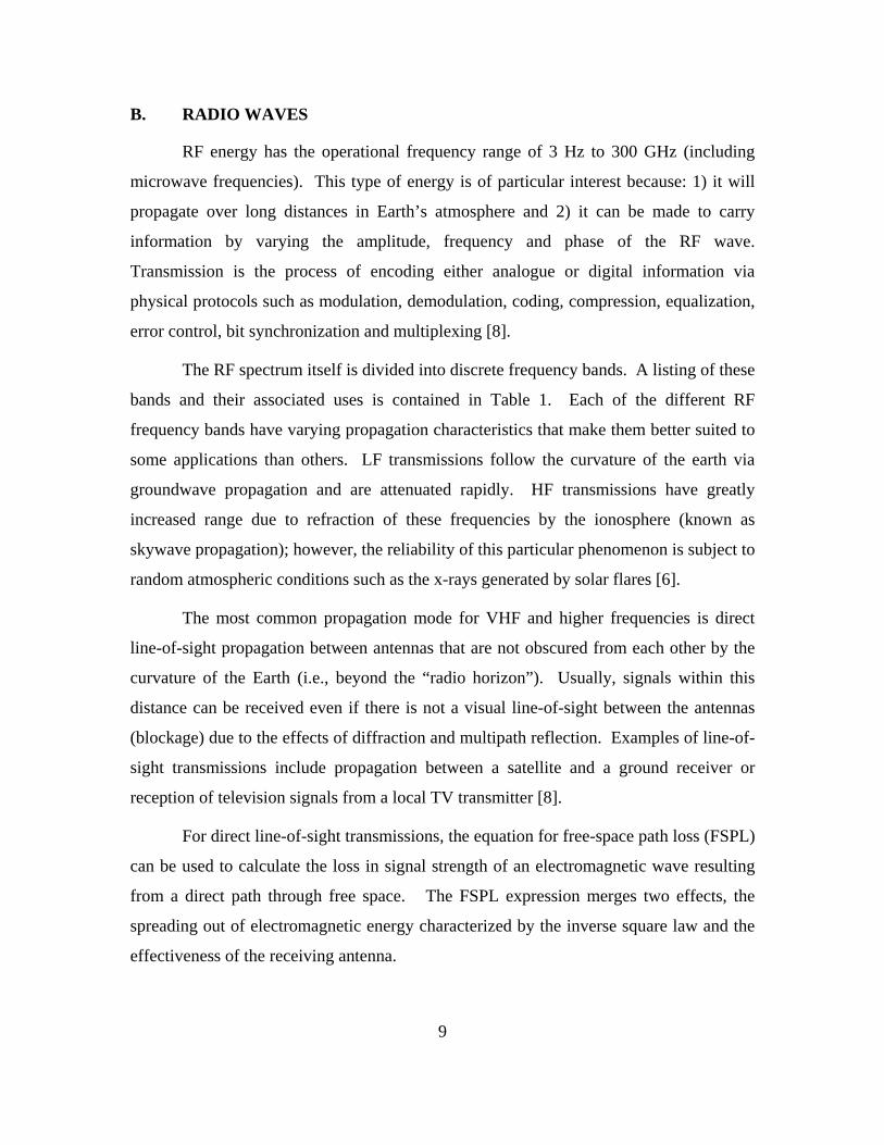
The first backpack “walkie-talkie” units, the SCR 300 (Figure 3), appeared in
1939 and transmitted on frequencies between 27 and 65 MHz. Unfortunately, these sets
were heavy and inconvenient to carry. Motorola (Galvin Manufacturing at the time)
developed the first handheld AM “handie-talkie” in 1940; it weighed 5 lbs and had a
range of one mile. The first portable FM two-way radio was a 40-pound backpack unit
that operated at 40–48 MHz with a range of 20 miles. All these devices ran on vacuum
tubes, high voltage dry cell batteries, and utilized half-duplex, “push-to-talk”
transmissions. These portable radio systems became key elements in the WWII strategic
“networking” capability to direct forces via radio relay [10].
Figure 3. SCR 300 Backpack Walkie Talkie
World War II also served as a catalyst for rapid improvements in radar resolution,
portability and range. The term RADAR is an acronym for RAdio Detection And
Ranging. Independent research and development efforts conducted in the United States,
Germany, France, and the Former Soviet Republic contributed to the development of
radar capability; however, it was the United Kingdom that first utilized a working
prototype for air defense and actually patented the device in 1935 [6].
16
17
That initial prototype employed the same fundamental physics used by modern
radar systems. The radar transmitter emits high-powered, electromagnetic waves that are
in phase when transmitted. When these waves come into contact with an object, some
small percentage is reflected back to the radar receiver. Since radio waves travel at a
known speed (the speed of light), the radar system can calculate the distance to an object
based on the time differential between transmitted and received signals. The phase
change of the return signal is also processed by the radar system to determine
characteristics such as the altitude, direction, and speed of the detected object. Due to
free space-loss considerations, the received signal is much weaker than the original
transmitted signal. To compensate for the weak return signal, many radar systems
(particularly long-range radars) have extremely powerful transmitters. As a result, EMI
became a real concern for the electronic equipment that had to successfully operate in
close proximity to the strong RF fields generated by these transmitters.
After the war, military organizations around the world recognized the importance
of measuring, analyzing and preventing potential EMC problems. Test procedures and
standards were developed for evaluating the ability of hardware to operate in harsh
military EMEs. Driven primarily by the needs of the military, EMC emerged as an
engineering discipline focused on diagnosing, solving and preventing EMI [4].
C. COMMERCIAL USE
For most of the twentieth century, public consumption of RF technologies was
limited to radio and television. Table 2 contains the broadcast frequencies associated
with these mediums.
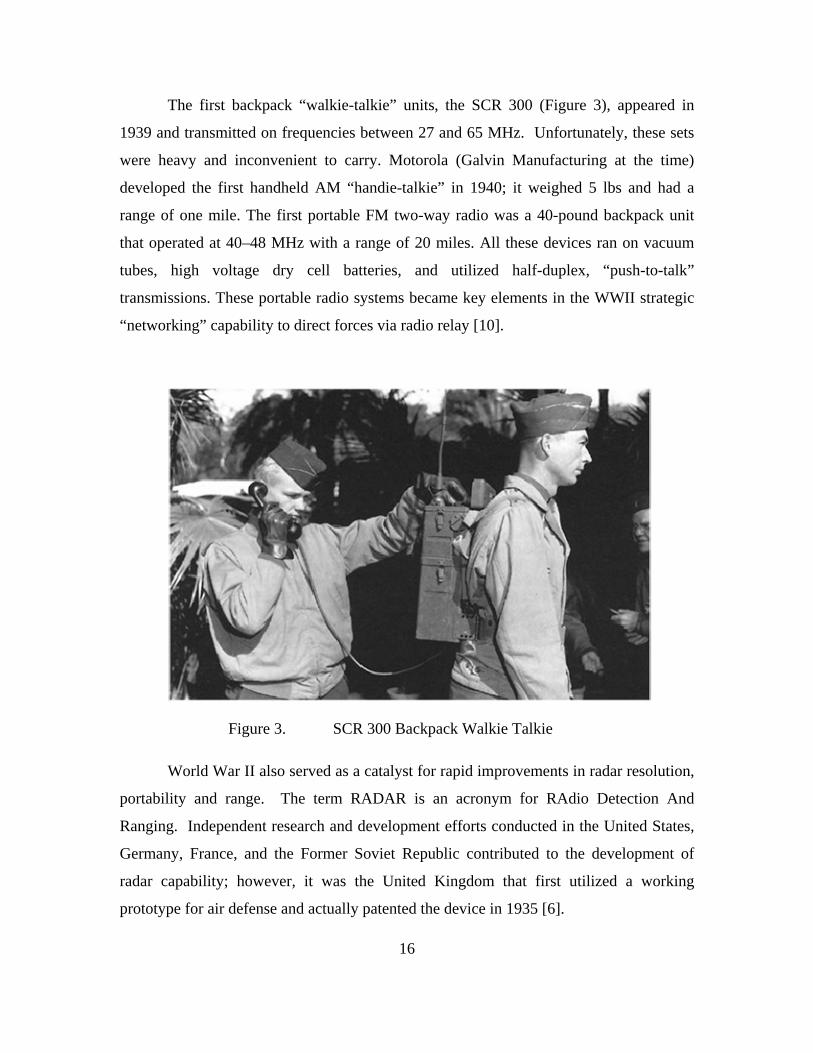
Table 2. Broadcast Frequencies.
Transmission Type Band Frequency Longwave AM Radio LF 148.5 - 283.5 kHz Mediumwave AM Radio MF 530 kHz - 1710 kHz Shortwave AM Radio HF 3 MHz - 30 MHz TV Band I (Channels 2 - 6) VHF 54 MHz - 88 MHz FM Radio Band II VHF 88 MHz - 108 MHz TV Band III (Channels 7 - 13) VHF 174 MHz - 216 MHz TV Bands IV & V (Channels 14 - 69) UHF 470 MHz - 806 MHz

Amplitude modulation (AM) radio was the first RF signal accessible to the
general public. Although, the first experimental AM broadcast was conducted in 1906,
licensed commercial AM radio services did not begin until the 1920s. The AM signal is
based on variations in radio wave amplitude at a particular frequency (Figure 4). These
changes in the signal voltage are then amplified to drive a loudspeaker. AM radio is
broadcast on several frequency bands: Long-wave (148.5 kHz–283.5 kHz), Medium-
wave (520 kHz–1,610 kHz), and short-wave (1.711 MHz–30.0 MHz). Medium wave is
actually the familiar “AM Radio” used for U.S. commercial broadcasting [8].
Figure 4. AM (top) and FM (bottom) Modulated Signals [After 5]
Although AM radio was the dominant form of radio broadcast for the first 80
years of the 20th century, the use of frequency modulation (FM) broadcasting was also
18
19
ok an additional 30 years before FM
listener
households had a television set in 1946,
55.7%
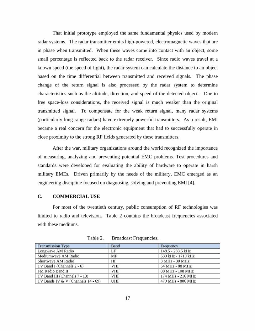
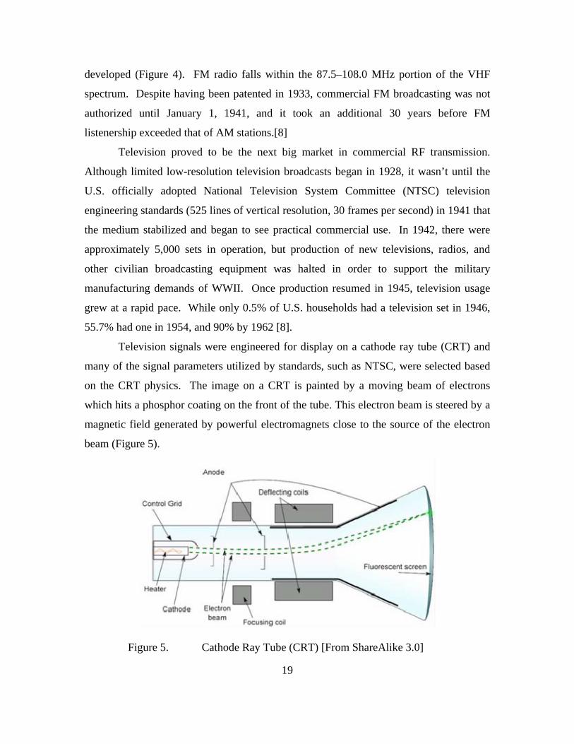
nerated by powerful electromagnets close to the source of the electron
beam (Figure 5).
Figure 5. Cathode Ray Tube (CRT) [From ShareAlike 3.0]
developed (Figure 4). FM radio falls within the 87.5–108.0 MHz portion of the VHF
spectrum. Despite having been patented in 1933, commercial FM broadcasting was not
authorized until January 1, 1941, and it to
ship exceeded that of AM stations.[8]
Television proved to be the next big market in commercial RF transmission.
Although limited low-resolution television broadcasts began in 1928, it wasn’t until the
U.S. officially adopted National Television System Committee (NTSC) television
engineering standards (525 lines of vertical resolution, 30 frames per second) in 1941 that
the medium stabilized and began to see practical commercial use. In 1942, there were
approximately 5,000 sets in operation, but production of new televisions, radios, and
other civilian broadcasting equipment was halted in order to support the military
manufacturing demands of WWII. Once production resumed in 1945, television usage
grew at a rapid pace. While only 0.5% of U.S.
had one in 1954, and 90% by 1962 [8].
Television signals were engineered for display on a cathode ray tube (CRT) and
many of the signal parameters utilized by standards, such as NTSC, were selected based
on the CRT physics. The image on a CRT is painted by a moving beam of electrons
which hits a phosphor coating on the front of the tube. This electron beam is steered by a
magnetic field ge
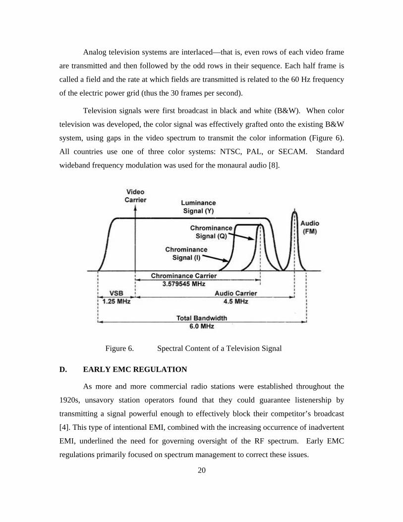
Analog television systems are interlaced—that is, even rows of each video frame
are transmitted and then followed by the odd rows in their sequence. Each half frame is
called a field and the rate at which fields are transmitted is related to the 60 Hz frequency
of the electric power grid (thus the 30 frames per second).
Television signals were first broadcast in black and white (B&W). When color
television was developed, the color signal was effectively grafted onto the existing B&W
system, using gaps in the video spectrum to transmit the color information (Figure 6).
All countries use one of three color systems: NTSC, PAL, or SECAM. Standard
wideband frequency modulation was used for the monaural audio [8].
Figure 6. Spectral Content of a Television Signal
D. EARLY EMC REGULATION
As more and more commercial radio stations were established throughout the
1920s, unsavory station operators found that they could guarantee listenership by
transmitting a signal powerful enough to effectively block their competitor’s broadcast
[4]. This type of intentional EMI, combined with the increasing occurrence of inadvertent
EMI, underlined the need for governing oversight of the RF spectrum. Early EMC
regulations primarily focused on spectrum management to correct these issues.
20
21
Spectrum management is a process that allows the most effective use of available
radio frequencies by the greatest number of users while simultaneously limiting EMI.
Spectrum management involves three related processes: allocation, allotment, and
assignment. Allocation establishes a specific frequency band for a specific service,
allotment partitions the allocation into discrete channels, and assignment actually licenses
a given transmitter to use an allotment.
American spectrum oversight began with the Wireless Telegraphy Board in 1904
and actual wireless legislation began in 1912 with the establishment of the Radio Act to
deal with allocation of frequencies. This Act was superseded by the Radio Act of 1927,
which divided authority for spectrum allocation between the Federal Radio Commission
for commercial users and the Department of Commerce for federal needs. The
Interdepartmental Radio Advisory Committee (IRAC), which had previously been
established in 1922 to coordinate federal spectrum use, was now tasked by the
Department of Commerce to perform this function. Finally, the Communications Act of
1934 was enacted. This Act established the Federal Communications Commission (FCC)
as the regulatory agency with jurisdiction over non-federal spectrum use [5].
Across the Atlantic, the International Electrotechnical Commission (IEC)
established the International Special Committee on Radio Interference (CISPR) in 1933
to deal with the EMI problem. CISPR subsequently published a series of technical
documents that established standard measurement and test techniques and recommended
emission and immunity limits. These standards have evolved and endured over the years
and still provide the foundation for most of today’s commercial EMC regulations and
guidance [4].
The military first established EMI emission requirements for equipment in 1945
with JAN-I-225 that mandated measurement of conducted and radiated EMR in the
frequency range 0.15–20 MHz. The first susceptibility requirement was introduced in
1950 in MIL-I-6181. As electronics became more sophisticated and diverse, requirements
evolved as well. A variety of requirements documents were issued over time with
increasing frequency requirements for emission measurements and an increasing
emphasis on susceptibility requirements. In 1967 these collective requirements were
22
consolidated into a series of three military standards: MIL-STD-461, MIL-STD-462, and
MIL-STD-463 [11]. The next chapter will examine how the introduction of integrated
circuits and microprocessors prompted a landslide of consumer electronics and shifted
the development of cutting-edge technologies away from the military and into the private
sector.

IV. MICROPROCESSORS AND CONSUMER DEMAND (1970–2009)
This chapter follows the development of spectrum-dependent equipment through
the latter part of the Twentieth Century, taking particular note of the impact of
computerization.
A. BACKGROUND
Looking across the timeline of consumer electronics, the single most significant
factor in the modern course of technology, spectrum use, and EMI is the development of
the integrated circuit (IC) in the 1960s, which, in turn, led to the manufacture of the first
microprocessor in the 1970s [12]. This breakthrough meant the end to vacuum tube
machines and made solid state consumer electronics an integral part of modern society
(Figure 7). As commercially manufactured electronics became increasingly widespread,
EMI problems moved from the battlefield to the suburbs. Escalating consumer demand
for the newest and latest and greatest gadget also led the private sector to ultimately
outpace DoD in the development of cutting-edge technologies.
Figure 7. Timeline of Consumer Electronics
23
24
B. EMITTERS IN HOMES
While earlier consumer electronics, such as televisions and radios were primarily
RF receivers, by 1970 RF transmitters were being incorporated into a growing number of
electronics designed for the average consumer. One of the first RF voice transmitters
designed and manufactured for the mass market is the Citizens’ Band (CB) radio. The
CB radio was conceived in 1945 as a means of providing the average citizen a radio band
for personal communication. Initially located in the 460 MHz–470 MHz UHF band, the
Class D CB service at 27 MHz was opened in 1958 (the 460 MHz–470 MHz band was
reassigned for business and public safety uses). CB use hit a peak in the mid- to late-
1970s, but has lost much of its appeal in the years since due to the development of
cellular technology.
Another early consumer use of RF technology is the motorized garage door
opener. Initially, garage door opener remote controls consisted of a simple transmitter
that sent an unmodulated signal on a single frequency. As this technology became more
common, users found that they could open their neighbor’s garage door as well. To
rectify this, systems first adopted a selectable digital code (one of 256 presets) and
eventually transitioned to a more secure rolling code protocol. Garage door openers use a
frequency spectrum range between 300–400 MHz [13].
The first widespread use of home radar equipment wasn’t used to detect aircraft,
but to cook dinner. Raytheon stumbled upon the concept of using microwaves to cook
food while constructing magnetrons for radar sets in 1945. In the 1960s, Litton
developed the short, wide configuration of the “Radarange,” otherwise known as the
microwave oven, which became a common household appliance by the late 1970s. The
oven works by passing non-ionizing microwave radiation at a frequency of 2.45 GHz
through food. Both 5.8 GHz and 24.125 GHz were considered for microwave cooking,
but were ultimately disregarded due to the high cost of power generation at these
frequencies. The microwave has become another mainstay of society; it is currently
estimated that more than 90% of American households have a microwave oven [14].

25
C. PERSONAL COMPUTING
Perhaps the most significant direct outgrowth of microprocessor technology is the
development and resulting proliferation of personal computers. Apple Computers
introduced the world’s first personal computer, the Apple II, in 1977 [15]. Throughout
the late 1970s and into the 1980s, computers were further developed for household use.
In 2001, 125 million personal computers were shipped in comparison to 48 thousand in
1977. Gordon Moore foresaw this growth when he postulated the famous “Moore’s
Law” in 1965—that every 18 months the capacity of the chip will double while its price
drops. As of June 2008, the number of personal computers in use worldwide hit one
billion, while another billion is expected to be in use by 2014. Although not readily
apparent, a personal computer will emit an RF signal at the clock frequency of the
system. These emissions become a greater concern as processor clock speeds climb
higher into the gigahertz range. For this reason, personal computers and other devices
that contain clocks or oscillators but that do not deliberately generate RF emissions are
classified by the FCC as “unintentional radiators” (and are subject to minimal
requirements for radiated emissions).
D. WIRELESS TELEPHONY
The first instance of a mass-market “wireless telephone” occurred in the early
1980s with the introduction of the cordless phone. Although still physically connected to
the service provider via a “hard-line,” the cordless handset maintains a short-range
wireless link to the charger/base station. Over the years, the FCC has approved cordless
phone operation in several shared frequency bands. The earliest cordless phones
operated at 1.7 MHz, but these models were soon replaced by phones that operated at 43–
50 MHz. Although the latter model had a large install base by the early 1990s, neither of
these phones is still in production. Virtually all telephones currently sold in the U.S. use
the 900 MHz, 1.9 GHz, 2.4-GHz, or 5.8 GHz bands, though legacy phones remain in use
on the older bands. The recently allocated 1.9 GHz band is used by the popular DECT
phone standard and is considered more secure than the other shared frequencies.

26
The next logical step in wireless phone technology was to eliminate the hard-line
altogether and link directly to the provider via a wireless signal. This was the principle
behind the development of the cellular telephone. Although the “cell” model for mobile
phone base stations was first developed by Bell Labs in the 1960s, it wasn’t until the
early 1990s that cell phones were widely used. This change was largely due to the
smaller and more convenient form factor made possible by advancements in digital
component miniaturization and improvements in battery technology. In the years since,
cell phones have become a staple of modern society. The International
Telecommunication Union estimated that mobile cellular subscriptions worldwide
reached approximately 4.1 billion at the end of 2006 [16]. Because cellular phones
utilize full-duplex, two-way transmissions, two frequencies are required for each call.
GSM-850 and GSM-1900 are the cell phone frequency standards used in the United
States and Canada. GSM-850 uses 824–849 MHz to send uplink information and 869–
894 MHz for the downlink. GSM-1900 uses 1850–1910 MHz for the uplink and 1930–
1990 MHz for the downlink [17].
A branch of technology closely related to the cell phone is the satellite phone.
This type of phone communicates directly with a satellite, which in turn relays calls to a
base station or another satellite phone. A single satellite can provide coverage to a much
greater area than terrestrial base stations. Satellite radio in the U.S. uses 2.3 GHz for
DARS. The Iridium satellite phones utilize L-band spectrum between 1616 and 1626.5
MHz.
E. SATELLITE TELEVISION & RADIO
Although satellite technology has its roots in military applications (the military
aspects of satellite technology will be covered in following sections), its functionality
was quickly recognized and implemented by the private sector. RCA launched
SATCOM 1, the first satellite built specifically for television broadcasts, in 1975.
Hughes’s DirecTV, the first national high-powered upper Ku-band DBS system, went

27
online in 1994, followed by EchoStar’s Dish Network in 1996. The Dish Network and
DirecTV remain the two primary U.S. providers of subscription satellite television
service to this day.
Satellite transmissions start with a transmitting antenna or “dish” at an uplink
facility. The uplink dish is pointed toward a specific satellite and the uplinked signals are
transmitted within a specific frequency range and received by a satellite transponder
tuned to that range. The transponder then sends the downlink signal back at a different
frequency in order to avoid interference with the uplink signal. This downlink feed is the
signal received by the customer [18].
Satellite TV either operates in the C band for the traditional large dish fixed
satellite service or Ku band for direct-broadcast satellite. C-band transmission is
susceptible to terrestrial interference while Ku-band transmission is affected by rain.
Satellite radio uses the 2.3 GHz S band in North America and generally shares the
1.4 GHz L band with local Digital Audio Broadcasting (DAB) stations elsewhere.
Curvature of the earth limits the reach of the signal, but due to the high orbit of the
satellites, two or three are sufficient to provide coverage for an entire continent. Local
repeaters enable reception even if line of sight to the satellite is blocked. In the United
States and Canada, one holding company, Sirius XM Radio, operates the two satellite
radio services, after the acquisition of XM by Sirius in July 2008.
F. WIRELESS STANDARDS
In a century of incredible technological growth, the Internet may well stand as the
most influential development of the twentieth century. Although the origins of this entity
can be traced back to 1960s networking research projects, funding by the National
Science Foundation sparked new interest leading to the commercialized worldwide
network that was first popularized in the mid-1990s. As of 2009, an estimated quarter of
Earth’s population uses the services of the Internet. In a related domino effect, the
demand for connectivity to this resource has led to the development of commercial
wireless technologies that allow users to access Internet services from virtually any
location [19].
28
IEEE 802.11 is a widely implemented set of standards established in 1997 for the
implementation of wireless local area networks (WLAN) computer communication in the
2.4, 3.6 and 5 GHz frequency bands. 802.11b and 802.11g use the 2.4 GHz frequency
band, while 802.11a uses the 5 GHz band. 802.11b and g equipment is susceptible to
EMI from microwave ovens, cordless telephones and other emitters in this band.
Because 802.11a devices operate at a less congested frequency, they are less likely to
experience EMI; however, the higher frequency reduces the effective range and signals
are absorbed more readily by walls and other solid objects [19].
IEEE 802.16 is a series of Wireless Broadband standards established in 1999 and
recently commercialized under the moniker Worldwide Interoperability for Microwave
Access (WiMAX) by the industry alliance known as the WiMAX Forum. The IEEE
802.16 specification was designed to operate between 2 to 11 GHz. The commercial
implementations are in the 2.3 GHz, 2.5 GHz, 3.5 GHz and 5.8 GHz ranges. Licensed
long-range (25 km) WiMAX Internet Access services in the 3.5–4.0 GHz range are
already operational in many countries. The FCC recently allocated spectrum in this range
for services in the U.S.
IEEE 802.20 and 802.22 are two additional standards still under development.
IEEE 802.20 or Mobile Broadband Wireless Access (MBWA) was established in 2002
with the goal of providing multi-vendor interoperable mobile broadband wireless access
networks in licensed bands between 1.6 and 2.3 GHz. IEEE 802.22 is a standard for
Wireless Regional Area Network (WRAN) that uses white spaces in UHF/VHF TV
bands between 54 and 862 MHz to bring broadband access to hard-to-reach, rural areas.
There are also several wireless standards that focus entirely on short range
hardware communication. Bluetooth is one such protocol that provides a way to connect
and exchange information between devices such as mobile phones, telephones, laptops,
personal computers, printers, etc. via a 2.4 GHz short-range RF signal. Although
developed in 1994, it has only been in recent years that the Bluetooth technology has seen
widespread adoption. Wireless USB (WUSB) is a high-bandwidth wireless extension to
USB based on Ultra-WideBand (UWB) wireless technology that is designed for use in
USB devices such as game controllers, printers, scanners, digital cameras, MP3 players,
hard disks and flash drives. WUSB operates in the 3.1–10.6 GHz band-range and spreads
communication over an ultra-wideband of frequencies [20].
G. MILITARY
Military Spectrum dependence continued to grow during the Korean and, in
particular, the Vietnam War. The early 1970s saw the peak of analog military
communications. High-fidelity transistorized combat radios became available in the field
and enabled infantry, armor, artillery, and air support to communicate directly with each
other. All total, the Department of Defense was operating nearly one million transmitters
at this time [3].
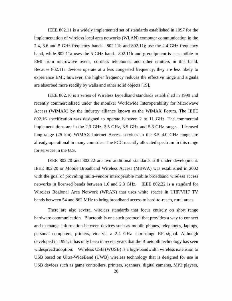
Figure 8. Single Channel Ground and Airborne Radio System (SINCGARS)
The Single Channel Ground and Airborne Radio System (SINCGARS) was the
next generation of military radio, replacing the mobile communication radios used in
Vietnam (Figure 8). The SINCGARS radio system operates on any of the 2,320
channels between 30 and 88 MHz and serves as a primary means of tactical command
and control for infantry, armor, and artillery units, and, airborne units. More than a
quarter-million receivers have been produced [3].
Several notable advancements in military radar technology also occurred during
the latter part of the 20th century.
29
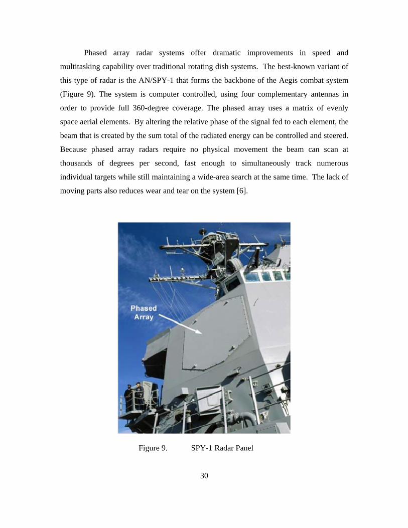
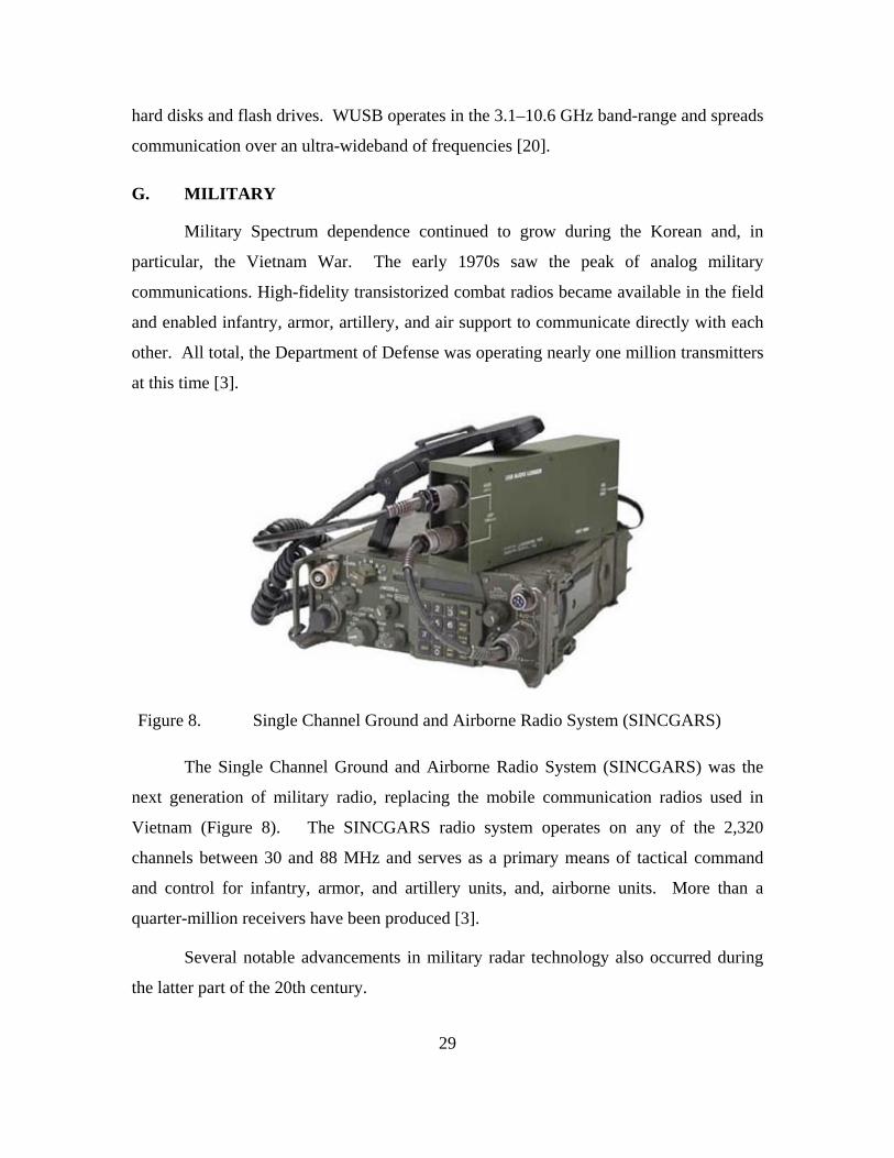
Phased array radar systems offer dramatic improvements in speed and
multitasking capability over traditional rotating dish systems. The best-known variant of
this type of radar is the AN/SPY-1 that forms the backbone of the Aegis combat system
(Figure 9). The system is computer controlled, using four complementary antennas in
order to provide full 360-degree coverage. The phased array uses a matrix of evenly
space aerial elements. By altering the relative phase of the signal fed to each element, the
beam that is created by the sum total of the radiated energy can be controlled and steered.
Because phased array radars require no physical movement the beam can scan at
thousands of degrees per second, fast enough to simultaneously track numerous
individual targets while still maintaining a wide-area search at the same time. The lack of
moving parts also reduces wear and tear on the system [6].
Figure 9. SPY-1 Radar Panel
30
31
A tracking system that works in concert with standard radar systems is the
Identification, friend or foe (IFF) emitters. This query-and-response system is used to
separate allied from enemy aircraft by assigning a unique identifier code to each friendly
aircraft's radio transponder. IFF operates in four modes in military aircraft and a fifth
mode is currently in the final stages of development. Mode 1 is a nonsecure method used
by ships to track aircraft and other ships. Mode 2 is used by aircraft to make carrier
controlled approaches to ships during inclement weather. Mode 3 is the standard system
and is also used by commercial aircraft to relay their position to ground controllers
throughout the world for air traffic control. Mode 4 is the secure, encrypted identification
system. Mode 5, also a secure identification system, features updated encryption
methods and will ultimately replace Mode 4 [3].
Military satellite systems are another key area of DoD spectrum technology. U.S.
military satellite communications have improved and expanded greatly over the past four
decades. U.S. satellite transmissions actually have their origins in early DoD
communication experiments involving reflecting RF signals off the Moon. Ultimately,
these experiments led to the deployment of Explorer 1 on January 31, 1958 (although
Sputnik 1, launched by the Soviet Union, proceeded Explorer by four months). Tacsat
and LES-5 and -6 were experimental satellites that demonstrated UHF (225- to 400-
megahertz) links with mobile terminals. The Fleet Satellite Communications
(FLTSATCOM) system was DoD’s first operational system dedicated to supporting
military operations. Most of the FLTSATCOM satellites transmitted in the UHF band
although there was a limited deployment of an EHF payload that had a 44-gigahertz
uplink and 20-gigahertz downlink. Leasat was a military satellite program that relied on
leased commercial satellite services in the X-band and UHF ranges. The FLTSATCOM
and Leasat satellites were replaced in 1999 by the UFO satellites. Additional protected
satellite systems include the MILSTAR and Air Force Satellite Communications
(AFSATCOM) systems. The United States Space Surveillance Network (SSN) has been
tracking space objects since 1957. The SSN currently tracks more than 560 operational
satellites [18].

32
The Joint Tactical Information Distribution System (JTIDS) is a secure, high-
capacity data link communications system for tactical combat. It uses L-band frequencies
(960–1215 MHz) and can handle large amounts of data at high speed. It supplies
integrated information distribution, position location, and identification capabilities. The
development of the JTIDS began in 1981. Multiservice operational testing was
completed in 1996 and implementation began in 1998 [3].
Link-16 is a tactical system providing communication, navigation, and
identification. Link-16 was used extensively and proved its effectiveness for the first time
during the Gulf War (1990–1991). Although primarily a data network, Link-16 also
supports voice communication [3].
The Navigation Satellite Timing and Ranging (NAVSTAR) global positioning
system is a U.S. Department of Defense system of 24 satellites that provide navigation
information and extremely accurate, three-dimensional position data to both civilian and
military users around the world. The satellites emit continuous signals on two different L-
band frequencies: 1575.42 MHz and 1227.6 MHz. The GPS program was initiated in
1973 and the first satellites were launched in 1978. The system's initial operational
capability was only reached on December 8, 1993, and full operational capability on
April 27, 1995. The placement of the satellites ensures that between five and eight
satellites are visible from any point on the earth [3].
The GPS system proved invaluable during the Gulf War in 1990. GPS enable
accurate navigation in featureless desert combat zones. The Gulf War was also the first
“net-centric” conflict. Forces made use of more than 60 communication satellites,
AWACS aircraft helped support a variety of joint land, sea, and air operations, and the
coalition maintained 59 communication centers and operated on over 7,000 RF
frequencies.
Another outgrowth of the Gulf War was the so-called “CNN effect,” i.e., the
impact of live broadcasting on military and foreign policy [21]. This was one of the first
instances of commercially available technology placing the military at a disadvantage. A
reporter could use a briefcase-size satellite phone to broadcast from the middle of a

33
combat zone. This effect has supposedly a primary motivator for military development
of non-lethal weapons, and RF “Pain Ray” technology in an effort to limit wartime
images of bloodied casualties.
The Iraq War is the first to be dominated by computerized and digital
communications. Joint forces make use of more than 100 communication satellites.
Communication has become real time and dependent on commercial IT innovations. The
Army Battle Command System (ABCS) enabled commanders to transmit orders,
intelligence, logistics information, and other useful data.
A challenge presented by the war in Iraq that DoD technology is still struggling to
overcome is the use of improvised explosive devices (IEDs). These devices are
constructed so that a receiver is connected to an electrical firing circuit and triggered by a
RF transmitter from a distance. Such a device can be triggered by a number of widely
available RF mechanisms including car alarms, wireless door bells, garage door openers,
pagers, and cell phones. The technology is simple, but the means to proactively defeat it
is incredibly complicated. One of the primary approaches initiated by DoD is the
development of a system of portable jamming devices that can be used to block radio
frequencies, such as cell phone signals. These high-powered jammers disrupting portions
of the radio spectrum that insurgents use to trigger IEDs. However, insurgents quickly
adapt to countermeasures, and new, more sophisticated IEDs are developed. Also,
counter-IED radio jammers can sometimes lock onto other U.S. electronic combat
systems because of a lack of coordination of spectrum usage. Unmanned Aerial Vehicles
(UAVs) can sometimes lose their radio control links due to ground-based radio
interference caused by counter-IED jammers once they are far away from their control
base.
Joint Tactical Radio System (JTRS) is the first in a new generation of software-
defined radios (SDRs) (Figure 10). The new equipment will integrate voice, data, and
video communications links, while providing interoperability with existing radio systems.
Spectrum segments used will range from 2 MHz to above 2 GHz. Development began in
1997 [3].
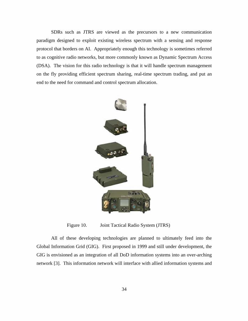
SDRs such as JTRS are viewed as the precursors to a new communication
paradigm designed to exploit existing wireless spectrum with a sensing and response
protocol that borders on AI. Appropriately enough this technology is sometimes referred
to as cognitive radio networks, but more commonly known as Dynamic Spectrum Access
(DSA). The vision for this radio technology is that it will handle spectrum management
on the fly providing efficient spectrum sharing, real-time spectrum trading, and put an
end to the need for command and control spectrum allocation.
Figure 10. Joint Tactical Radio System (JTRS)
All of these developing technologies are planned to ultimately feed into the
Global Information Grid (GIG). First proposed in 1999 and still under development, the
GIG is envisioned as an integration of all DoD information systems into an over-arching
network [3]. This information network will interface with allied information systems and
34

35
provide information assurance, interoperability, and information sharing across all DoD
assets and be available worldwide from either fixed or mobile connections—quite an
advancement from homing pigeons.
This grand vision for the future of warfare hinges on the underlying assumption
that there will be available spectrum to accomplish this global connectivity and sufficient
bandwidth to move these massive amounts of information. However, access is not
guaranteed, and loss of spectrum not only equates to reduced capability in the short-term,
it could very well undermine plans for future capability as well.
H. MILITARY USE OF COTS
Although the U.S. military has maintained a considerable edge over other
countries with respect to technological advancement, more and more, this technology is
being based on commercial developments as opposed to being developed in DoD labs.
With the rapid growth in the demand for consumer electronics over the past 25 years, it is
no longer the soldier’s need for reliable communication on the battlefield that drives the
miniaturization of portable communications; rather, it is the need for a cell phone to fit
conveniently into a 16-year-old girl’s purse that now drives this trend. The competitive
nature of the commercial market has created a situation where private industry outpaces
military development more often than not. The government role in technology has
shifted to more of a director than developer in that procurement decisions serve to speed
outside development. This approach is exemplified by the DoD transition to a capability-
based acquisition system.
DoD has recognized the fact that commercial-integration provides opportunities
for faster and lower costs in the development of military equipment. COTS use also
provides access to what has become a much larger industrial base. With these goals in
mind, the Secretary of Defense issued a directive in June 1994 requiring the military to
use performance-based requirements in procurements and to apply commercial
specifications and standards whenever possible. Recent U.S. Department of Defense
36
Procurement Reform policies expand on this guidance by encouraging the use of COTS
equipment as well. DoD has also acknowledged that there is some level of risk involved
with this policy.
Military command and control environments have a greater density of electronic
equipment sensitive to electromagnetic effects. At the same time, other military
environments, particularly Navy shipboard environments, have EMR emitters that
operate at very high power/energy levels (such as the AEGIS SPY-1 radar). Because
COTS equipment is not designed for either of these scenarios, military standards, such as
MIL-STD-461 and MIL-STD-464 or commercial equivalents must be enforced. In many
cases, the COTS equipment must be upgraded to meet these more rigorous military
needs.
The next chapter will examine MIL-STD-461 and MIL-STD-462 in an effort to
illustrate and establish the demands of the military EMEs.

37
V. MILITARY EMC GUIDELINES
This chapter examines the regulatory and environmental requirements related to
military EMC, EMI, and spectrum certification.
A. DOD SPECTRUM REGULATION
DoD use of the EM spectrum has become a pivotal aspect of warfighting
strategies. Few, if any, of the hundreds of advanced military weapon systems operate
without some form of spectrum access. Critical though this access may be, DoD has to
cooperate in the use of this resource with other Federal Agencies, local Governments and
private Industry. To provide adequate oversight for federal spectrum access, the National
Telecommunications and Information Administration (NTIA) was established in 1978 as
part of an Executive Branch reorganization. It transferred and combined functions of the
White House’s Office of Telecommunications Policy (OTP) and the Commerce
Department’s Office of Telecommunications. NTIA performs its spectrum management
function through the Office of Spectrum Management (OSM) governed by the NTIA
Manual of Regulations and Procedures for Federal Radio Frequency Management. Two
committees advise the OSM: the IRAC and the Spectrum Planning and Policy Advisory
Committee (SPAC).
All spectrum dependent equipment/systems owned and operated by the DoD
require spectrum certification (Figure 11). Equipment spectrum certification is supported
by the Military Communications-Electronics Board (MCEB) FP Equipment Spectrum
Guidance Permanent Working Group (ESGPWG) and the NTIA Spectrum Planning
Subcommittee (SPS) and Frequency Assignment Subcommittee (FAS) [5].
The MCEB coordinates frequency requests from the service branches and guides
the coordination of NTIA spectrum allotments and technical directives. The Joint
Frequency Panel (JFP) reviews acquisition proposals for frequency use and must provide
approval before funds are authorized for the development of new spectrum-dependent
equipment and the Frequency Assignment Subcommittee of IRAC must assign an
operational frequency prior to actual operation of developmental equipment.

Most DoD applications for frequency assignments are in the VHF, UHF, and SHF
frequency bands, but very little spectrum is designated for the exclusive use of the
military. In fact, the massive monetary potential of spectrum auctions to the private
sector has brought considerable congressional pressure to surrender large portions of
what little spectrum is still controlled by the military. This trend is cause for concern
since most of the frequencies used by DoD are selected because they work best with the
physics of the systems that use them.
ESGW orking Group
Review
Program Off ice InitatesDD Form 1494 Process
NMSCReview
NAVSEA 05W43Review
Contractor/VendorGenerates DD Form 1494
Frequency AssignmenProposals
Approved Form Returned toCustomer/ProgramOff ice/Requestor
MCEB GuidanceIncorporated
Supportability CommentsReturned to FMO
Direct Agency(FAA/FCC/etc)
Review and Coordinat ion
NTIA/SPSUS&P
Review and Coordinat ion
Form isComplete?
Informat ionis Accurate?
Coordination Package(s)are Generated
COCOMs forHost Nation Coord
Approved?J-12 Steering Member Signs
Guidance Package
START
END
OPNAV N6F13
For UseOutsideUS&P?
1494 Changes to J -12
ESGWorking Group
Final Review
US&PGovt.Freq?
US&PCommercial
Freq?
AND
CriticalComments?
YES
NO
YES
YES
YES
YES
YES
NO
NO
NO
NO
NO
NO
YES
Figure 11. DoD Spectrum Certification Flow Diagram
B. MILITARY EMC REQUIREMENTS
1. Overview
DoD policy requires all electrical and electronic systems, subsystems, and
equipment, including ordnance containing Electrically Initiated Devices, to be mutually
compatible in their intended EME without causing or suffering unacceptable mission
degradation due to Electromagnetic Environmental Effects (E3). Accordingly,
38

39
appropriate E3 requirements must be imposed to ensure compatibility with co-located
equipment within the applicable external EME and to address hazards of electromagnetic
radiation to ordnance (HERO), personnel (HERP), and fuel (HERF). In addition,
national, international, and DoD policies and procedures for the management and use of
the EM spectrum direct program managers developing spectrum-dependent systems or
equipment to consider Spectrum Supportability requirements and E3 control early in the
development process and throughout the acquisition life cycle. The two DoD documents
used to establish the specific requirements necessary to ensure these levels of
compatibility are MIL-STD-461 and MIL-STD-464.
2. MIL-STD-461
In 1966, EMC subject matter experts compiled EMC regulations from roughly 20
existing requirements documents into a single series of specifications that were released
in 1967: MIL-STD-461 (EMC requirements), MIL-STD-462 (EMC test set-up and
methodology), and MIL-STD-463 (EMC definitions and acronyms). The first revision of
MIL-STD-461 (revision A) was issued in 1968. By 1993, MIL-STD-461 and MIL-STD-
462 were updated to revision D and MIL-STD- 463 was canceled (ANSI C63.14 was
used in its place). In 1999, MIL-STD-461 and MIL-STD-462 were combined into a
single standard, MIL-STD- 461E. The latest revision, MIL-STD-461F was issued in
December 2008.
MIL-STD-461F is a system-level test that specifies EMC requirements and limits
based on the operational platform for deployment (surfaces ships, aircraft, etc.) and
location on that platform (internal or external). The overall requirement is comprised of
eighteen sub-tests that cover diverse system characteristics ranging from emissions
conducted via power leads to spurious and harmonic radiated emissions. This testing is
not inexpensive. The five core tests (RS103, RE102, CS101, CS114 and CS116) will
require roughly two days of lab time; the entire standard, seven to ten days. Not all tests
are required for every platform. Table V from MIL-STD-461F provides a matrix of the
required tests for each of the platform environments—this information is reproduced in
Table 3.
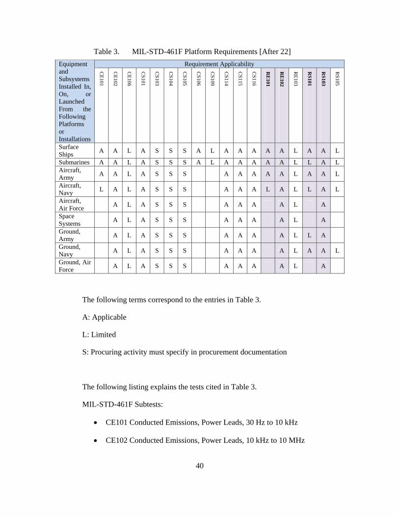
40
Table 3. MIL-STD-461F Platform Requirements [After 22]
Requirement Applicability Equipment and Subsystems Installed In, On, or Launched From the Following Platforms or Installations
CE
101
CE
102
CE
106
CS
101
CS
103
CS
104
CS
105
CS
106
CS
109
CS
114
CS
115
CS
116
RE
101
RE
102
RE
103
RS
101
RS
103
RS
105
Surface Ships
A A L A S S S A L A A A A A L A A L
Submarines A A L A S S S A L A A A A A L L A L Aircraft, Army
A A L A S S S A A A A A L A A L
Aircraft, Navy
L A L A S S S A A A L A L L A L
Aircraft, Air Force
A L A S S S A A A A L A
Space Systems
A L A S S S A A A A L A
Ground, Army
A L A S S S A A A A L L A
Ground, Navy
A L A S S S A A A A L A A L
Ground, Air Force
A L A S S S A A A A L A
The following terms correspond to the entries in Table 3.
A: Applicable
L: Limited
S: Procuring activity must specify in procurement documentation
The following listing explains the tests cited in Table 3.
MIL-STD-461F Subtests:
CE101 Conducted Emissions, Power Leads, 30 Hz to 10 kHz
CE102 Conducted Emissions, Power Leads, 10 kHz to 10 MHz

41
CE106 Conducted Emissions, Antenna Terminal, 10 kHz to 40 GHz
CS101 Conducted Susceptibility, Power Leads, 30 Hz to 150 kHz
CS103 Conducted Susceptibility, Antenna Port, Intermodulation, 15 kHz
to 10 GHz
CS104 Conducted Susceptibility, Antenna Port, Rejection of Undesired
Signals, 30 Hz to 20 GHz
CS105 Conducted Susceptibility, Antenna Port, Cross-Modulation, 30 Hz
to 20 GHz
CS106 Conducted Susceptibility, Transients, Power Leads
CS109 Conducted Susceptibility, Structure Current, 60 Hz to 100 kHz
CS114 Conducted Susceptibility, Bulk Cable Injection, 10 kHz to 200
MHz
CS115 Conducted Susceptibility, Bulk Cable Injection, Impulse Excitation
CS116 Conducted Susceptibility, Damped Sinusoidal Transients, Cables
and Power Leads, 10 kHz to 100 MHz
RE101 Radiated Emissions, Magnetic Field, 30 Hz to 100 kHz
RE102 Radiated Emissions, Electric Field, 10 kHz to 18 GHz
RE103 Radiated Emissions, Antenna Spurious and Harmonic Outputs, 10
kHz to 40 GHz
RS101 Radiated Susceptibility, Magnetic Field, 30 Hz to 100 kHz
RS103 Radiated Susceptibility, Electric Field, 2 MHz to 40 GHz
RS105 Radiated Susceptibility, Transient Electromagnetic Field
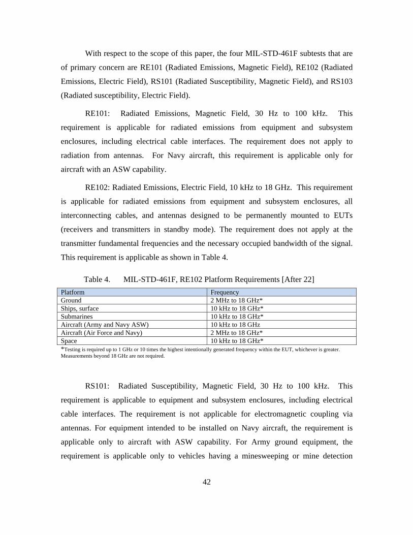
42
With respect to the scope of this paper, the four MIL-STD-461F subtests that are
of primary concern are RE101 (Radiated Emissions, Magnetic Field), RE102 (Radiated
Emissions, Electric Field), RS101 (Radiated Susceptibility, Magnetic Field), and RS103
(Radiated susceptibility, Electric Field).
RE101: Radiated Emissions, Magnetic Field, 30 Hz to 100 kHz. This
requirement is applicable for radiated emissions from equipment and subsystem
enclosures, including electrical cable interfaces. The requirement does not apply to
radiation from antennas. For Navy aircraft, this requirement is applicable only for
aircraft with an ASW capability.
RE102: Radiated Emissions, Electric Field, 10 kHz to 18 GHz. This requirement
is applicable for radiated emissions from equipment and subsystem enclosures, all
interconnecting cables, and antennas designed to be permanently mounted to EUTs
(receivers and transmitters in standby mode). The requirement does not apply at the
transmitter fundamental frequencies and the necessary occupied bandwidth of the signal.
This requirement is applicable as shown in Table 4.
Table 4. MIL-STD-461F, RE102 Platform Requirements [After 22]
Platform Frequency Ground 2 MHz to 18 GHz* Ships, surface 10 kHz to 18 GHz* Submarines 10 kHz to 18 GHz* Aircraft (Army and Navy ASW) 10 kHz to 18 GHz Aircraft (Air Force and Navy) 2 MHz to 18 GHz* Space 10 kHz to 18 GHz* *Testing is required up to 1 GHz or 10 times the highest intentionally generated frequency within the EUT, whichever is greater. Measurements beyond 18 GHz are not required.
RS101: Radiated Susceptibility, Magnetic Field, 30 Hz to 100 kHz. This
requirement is applicable to equipment and subsystem enclosures, including electrical
cable interfaces. The requirement is not applicable for electromagnetic coupling via
antennas. For equipment intended to be installed on Navy aircraft, the requirement is
applicable only to aircraft with ASW capability. For Army ground equipment, the
requirement is applicable only to vehicles having a minesweeping or mine detection

43
capability. For submarines, this requirement is applicable only to equipment and
subsystems that have an operating frequency of 100 kHz or less and an operating
sensitivity of 1 μV or better (such as 0.5 μV).
RS103: Radiated susceptibility, Electric Field, 2 MHz to 40 GHz. This
requirement is applicable to equipment and subsystem enclosures and all interconnecting
cables. The EUT shall not exhibit any malfunction, degradation of performance, or
deviation from specified indications, beyond the tolerances indicated in the individual
equipment or subsystem specification, when subjected to the radiated electric fields listed
in Table 7 and modulated as specified in Table 5. Up to 30 MHz, the requirement shall be
met for vertically polarized fields. Above 30 MHz, the requirement shall be met for both
horizontally and vertically polarized fields. Circular polarized fields are not acceptable.
This requirement is applicable as shown in Table 5 [22].
Table 5. MIL-STD-461F, RS103 Platform Requirements [After 22]
Platform Frequency Army ships; Army aircraft, including flight line; Navy (except aircraft); and optional* for all others
2 MHz to 30 MHz
All (except Navy aircraft) 30 MHz to 100 MHz All 100 MHz to 1 GHz All 1 GHz to 18 GHz Optional* for all 18 GHz to 40 GHz *Required only if specified in the procurement specification There is no requirement at the tuned frequency of antenna-connected receivers, except for surface ships and submarines.
3. MIL-STD-464
Although MIL-STD-461 serves the military needs to ensure component or system
level EMC, it is not designed to assess or certify intra-system or inter-system EMC [23].
DoD recognized the need for a standard in order to make these platform-level EMC
assessments. As a result, a series of requirements were enacted and revised over the
years, including MIL-E-6051D, MIL-STD-1818A, and MIL-B-5087B. The current
standard, MIL-STD-464, superseded MIL-STD-1385B in 1997, was updated to MIL-
STD-464A in 2002 and will be updated to MIL-STD-464B at the end of 2009.
Specifically, MIL-STD-464A requirements, verification criteria, and contractor tasks for
E3 protection of airborne, ground, and support systems. These effects include EMC and
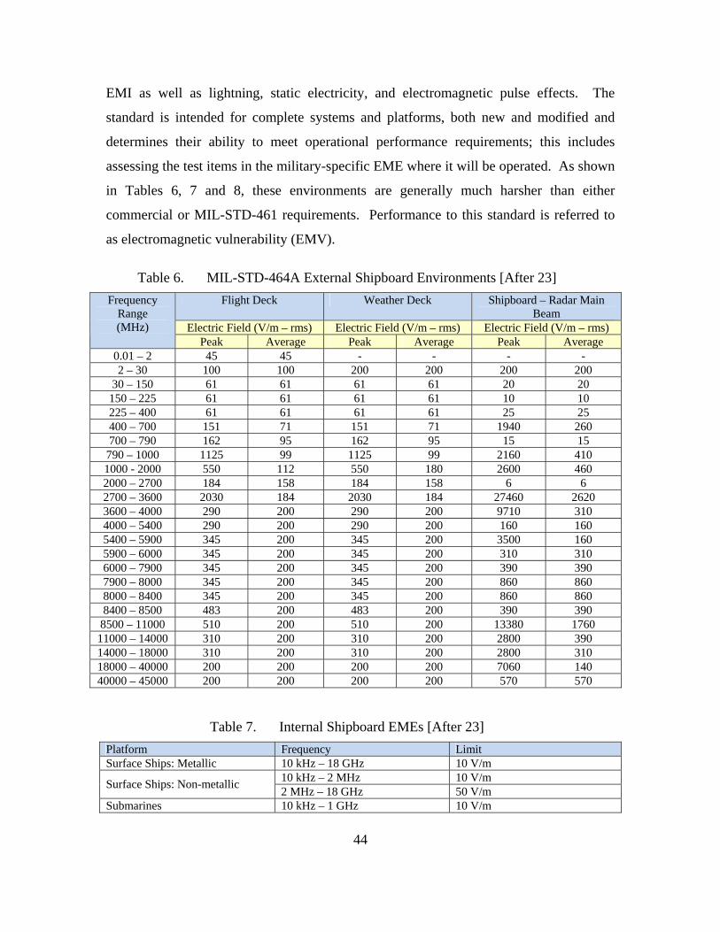
44
EMI as well as lightning, static electricity, and electromagnetic pulse effects. The
standard is intended for complete systems and platforms, both new and modified and
determines their ability to meet operational performance requirements; this includes
assessing the test items in the military-specific EME where it will be operated. As shown
in Tables 6, 7 and 8, these environments are generally much harsher than either
commercial or MIL-STD-461 requirements. Performance to this standard is referred to
as electromagnetic vulnerability (EMV).
Table 6. MIL-STD-464A External Shipboard Environments [After 23]
Flight Deck Weather Deck Shipboard – Radar Main Beam
Electric Field (V/m – rms) Electric Field (V/m – rms) Electric Field (V/m – rms)
Frequency Range (MHz)
Peak Average Peak Average Peak Average 0.01 – 2 45 45 - - - - 2 – 30 100 100 200 200 200 200
30 – 150 61 61 61 61 20 20 150 – 225 61 61 61 61 10 10 225 – 400 61 61 61 61 25 25 400 – 700 151 71 151 71 1940 260 700 – 790 162 95 162 95 15 15 790 – 1000 1125 99 1125 99 2160 410 1000 - 2000 550 112 550 180 2600 460 2000 – 2700 184 158 184 158 6 6 2700 – 3600 2030 184 2030 184 27460 2620 3600 – 4000 290 200 290 200 9710 310 4000 – 5400 290 200 290 200 160 160 5400 – 5900 345 200 345 200 3500 160 5900 – 6000 345 200 345 200 310 310 6000 – 7900 345 200 345 200 390 390 7900 – 8000 345 200 345 200 860 860 8000 – 8400 345 200 345 200 860 860 8400 – 8500 483 200 483 200 390 390
8500 – 11000 510 200 510 200 13380 1760 11000 – 14000 310 200 310 200 2800 390 14000 – 18000 310 200 310 200 2800 310 18000 – 40000 200 200 200 200 7060 140 40000 – 45000 200 200 200 200 570 570
Table 7. Internal Shipboard EMEs [After 23]
Platform Frequency Limit Surface Ships: Metallic 10 kHz – 18 GHz 10 V/m
10 kHz – 2 MHz 10 V/m Surface Ships: Non-metallic
2 MHz – 18 GHz 50 V/m Submarines 10 kHz – 1 GHz 10 V/m

45
Table 8. External EME for Ground Systems [After 23]
Electric Field (V/m – rms)
Frequency Range (MHz) Peak Average
0.01 – 2 25 25 2 – 250 50 50
250 – 1000 1500 50 1000 – 10000 2500 50 10000 – 40000 1500 50 40000 - 45000 - -
The levels cited in MIL-STD-464A are often extremely high; however, they were
established on the basis of measured data taken in the respective environments they
represent. Building on this understanding of the military regulations and requirements,
the next chapter will examine the same aspects of the commercial equipment.

46
THIS PAGE INTENTIONALLY LEFT BLANK

47
VI. COMMERCIAL EMC GUIDELINES
This chapter examines the regulatory and environmental requirements related to
commercial EMC, EMI, and spectrum certification.
A. COMMERCIAL EMI REGULATION
The growing popularity and diversity of consumer electronics that began in the
1970s compounded the problem of EMI. Previously, the use of vacuum tube technology
largely limited EMI to instances of transmission overlap, where one signal would “step
on” another. With the advent of modern digital circuitry, faster switching speeds
increased emissions while lower circuit voltages increased susceptibility. As a result,
equipment became more sensitive to EMR induced current and E3 related upsets. As
governments became aware of these growing issues, international organizations were
formed development and maintain commercial product standards for EMC [9].
B. EUROPE
The governing bodies in the European Union with respect to EMC include the
IEC, CISPR, and the European Committee for Electrotechnical Standardization
(CENELEC). The IEC coordinates international standardization and related matters,
while CENELEC and CISPR are largely responsible for approving detailed EMC
standards to demonstrate compliance with the EMC Directive [5].
Products sold in the European Union must be in compliance with EMC Directive,
89/392/EEC. Article 4 of this document states:
The apparatus...shall be so constructed that (a) the EMC disturbance it generates does not exceed a level allowing radio and telecommunications equipment and other apparatus to operate as intended; (b) the apparatus has an adequate level of intrinsic immunity of EMC disturbance to enable it to operate as intended. [9]
It is the manufacturer’s responsibility to collect and maintain the necessary
technical artifacts to support the product “conformity” claim. This supporting evidence is

48
assembled in a Technical Construction File (TCF). A TCF exists for each product sold in
the European Union and results of EMC testing are included in the TCF [9].
IEC has issued four generic standards: IEC 61000-6-1, 2, 3, and 4, which specify
emission and immunity requirements for two classes of equipment: “industrial” or
“residential, commercial, and light industrial.” Generic standards are also available for
products that do not fit in any of the previous categories. The generic standards list the
individual test standards (generally, IEC and CISPR documents) that are applicable and
the limits that apply [24].
Table 9. IEC Generic Radiated Emissions Requirements (Electric Field).
Standard Frequency Environment Limit Reference Standard
30 – 230 MHz 30 dB(µV/m) at 10 m IEC 61000-6-3
230 – 1,000 MHz Residential
37 dB(µV/m) at 10 m CISPR 22
30 – 230 MHz 30 dB(µV/m) at 30 m IEC 61000-6-4
230 – 1,000 MHz Industrial
37 dB(µV/m) at 30 m CISR 11
Compliance with provision (a) of the EMC Directive is generally established by
meeting an actual set of emissions test requirements. The IEC 61000 test method deemed
most useful for evaluating emissions emanating from equipment is IEC 61000-6-4
(industrial emission limits). The standard was prepared by the International Special
Committee on Radio Interference (CISPR) and adopted by CENELEC. IEC 61000-6-3
(residential emission limits) and 61000-6-4-4 are generic standards that reference
product-family standards like CISPR 11, CISPR-14-1, CISPR 15, and CISPR 22 (Table
9). Compliance with the “intrinsic immunity” requirement of provision (b), however,
does not necessarily require test validation. A manufacturer can simply make a case that
design and construction of a device makes it robust enough to have intrinsic immunity.
Still, immunity testing in to levels representative of real-world environments is the best
way to demonstrate compliance. The IEC 61000-4 series of immunity standards consists
of 21 generic test methods developed to address upsets and malfunctions in electrical and
electronic devices. IEC 61000-4-3 covers test methods for evaluating the immunity of
equipment to radiated electric fields in the radio-frequency range (Table 10).
Table 10. IEC Immunity Requirements.
Standard Parameter Frequency Residential Limit Industrial Limit IEC 61000-4-3 Electric Field 80 – 1,000 MHz 3 V/m 10 V/m IEC 61000-4-8 Magnetic Field 50 – 60 Hz 3 A/m 30 A/m IEC 60945 Electric Field 80 – 2,000 MHz NA 10 V/m
Products that meet the EMC directive carry the “CE” mark that signifies the
manufacturer’s assertion of compliance (Figure 12). The CE marking is an acronym for
the French “Conformité Européenne.”
Figure 12. European Union “CE” Compliance Marking
C. UNITED STATES
1. Overview
In the United States, the FCC regulates non-federal government
telecommunications, grants authority to use radio frequencies or channels by issuing
licenses to private sector entities and local and state governments, and is directly
responsible to Congress. The Rules and Regulations that the FCC follows are codified in
Title 47 of the Code of Federal Regulations (CFR 47). The FCC imposed legal limits on
electromagnetic emissions produced by commercial digital equipment in response to the
increased number of systems that were interfering with wired and radio communications.
Test methods and limits tied to these requirements were based on CISPR publications.
FCC requirements pertaining to unlicensed intentional, unintentional, and
incidental radiation devices are contained in CFR 47, Part 15. There are two sets of
limits, one for residential areas and a second for industrial areas. Two other parts of CFR
47 also address license-free RF generators: Part 18 for so-called Industrial, Scientific, and
Medical (ISM) devices, and Part 95 for Personal Radio Services.
49
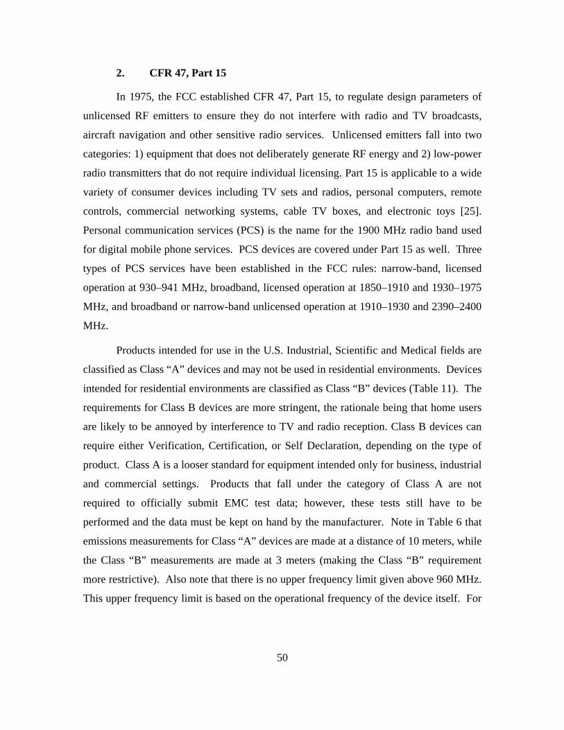
50
2. CFR 47, Part 15
In 1975, the FCC established CFR 47, Part 15, to regulate design parameters of
unlicensed RF emitters to ensure they do not interfere with radio and TV broadcasts,
aircraft navigation and other sensitive radio services. Unlicensed emitters fall into two
categories: 1) equipment that does not deliberately generate RF energy and 2) low-power
radio transmitters that do not require individual licensing. Part 15 is applicable to a wide
variety of consumer devices including TV sets and radios, personal computers, remote
controls, commercial networking systems, cable TV boxes, and electronic toys [25].
Personal communication services (PCS) is the name for the 1900 MHz radio band used
for digital mobile phone services. PCS devices are covered under Part 15 as well. Three
types of PCS services have been established in the FCC rules: narrow-band, licensed
operation at 930–941 MHz, broadband, licensed operation at 1850–1910 and 1930–1975
MHz, and broadband or narrow-band unlicensed operation at 1910–1930 and 2390–2400
MHz.
Products intended for use in the U.S. Industrial, Scientific and Medical fields are
classified as Class “A” devices and may not be used in residential environments. Devices
intended for residential environments are classified as Class “B” devices (Table 11). The
requirements for Class B devices are more stringent, the rationale being that home users
are likely to be annoyed by interference to TV and radio reception. Class B devices can
require either Verification, Certification, or Self Declaration, depending on the type of
product. Class A is a looser standard for equipment intended only for business, industrial
and commercial settings. Products that fall under the category of Class A are not
required to officially submit EMC test data; however, these tests still have to be
performed and the data must be kept on hand by the manufacturer. Note in Table 6 that
emissions measurements for Class “A” devices are made at a distance of 10 meters, while
the Class “B” measurements are made at 3 meters (making the Class “B” requirement
more restrictive). Also note that there is no upper frequency limit given above 960 MHz.
This upper frequency limit is based on the operational frequency of the device itself. For
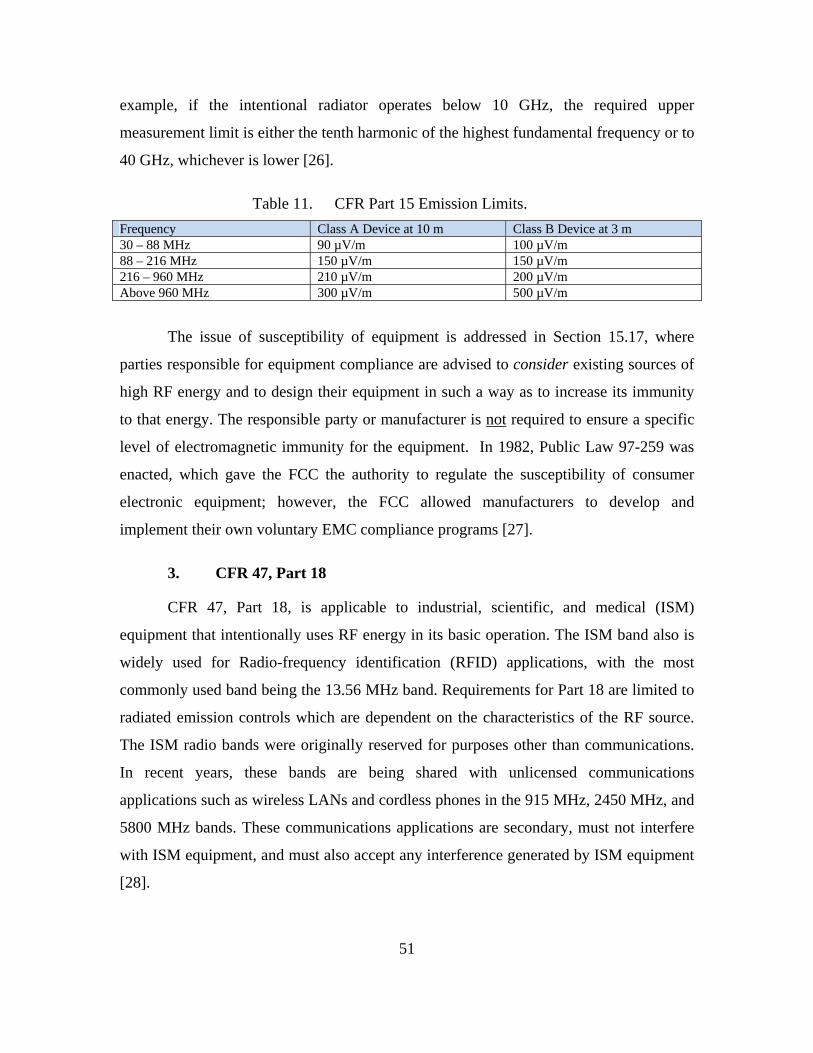
51
example, if the intentional radiator operates below 10 GHz, the required upper
measurement limit is either the tenth harmonic of the highest fundamental frequency or to
40 GHz, whichever is lower [26].
Table 11. CFR Part 15 Emission Limits.
Frequency Class A Device at 10 m Class B Device at 3 m 30 – 88 MHz 90 µV/m 100 µV/m 88 – 216 MHz 150 µV/m 150 µV/m 216 – 960 MHz 210 µV/m 200 µV/m Above 960 MHz 300 µV/m 500 µV/m
The issue of susceptibility of equipment is addressed in Section 15.17, where
parties responsible for equipment compliance are advised to consider existing sources of
high RF energy and to design their equipment in such a way as to increase its immunity
to that energy. The responsible party or manufacturer is not required to ensure a specific
level of electromagnetic immunity for the equipment. In 1982, Public Law 97-259 was
enacted, which gave the FCC the authority to regulate the susceptibility of consumer
electronic equipment; however, the FCC allowed manufacturers to develop and
implement their own voluntary EMC compliance programs [27].
3. CFR 47, Part 18
CFR 47, Part 18, is applicable to industrial, scientific, and medical (ISM)
equipment that intentionally uses RF energy in its basic operation. The ISM band also is
widely used for Radio-frequency identification (RFID) applications, with the most
commonly used band being the 13.56 MHz band. Requirements for Part 18 are limited to
radiated emission controls which are dependent on the characteristics of the RF source.
The ISM radio bands were originally reserved for purposes other than communications.
In recent years, these bands are being shared with unlicensed communications
applications such as wireless LANs and cordless phones in the 915 MHz, 2450 MHz, and
5800 MHz bands. These communications applications are secondary, must not interfere
with ISM equipment, and must also accept any interference generated by ISM equipment
[28].
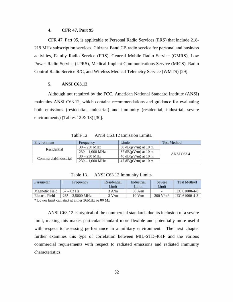
52
4. CFR 47, Part 95
CFR 47, Part 95, is applicable to Personal Radio Services (PRS) that include 218-
219 MHz subscription services, Citizens Band CB radio service for personal and business
activities, Family Radio Service (FRS), General Mobile Radio Service (GMRS), Low
Power Radio Service (LPRS), Medical Implant Communications Service (MICS), Radio
Control Radio Service R/C, and Wireless Medical Telemetry Service (WMTS) [29].
5. ANSI C63.12
Although not required by the FCC, American National Standard Institute (ANSI)
maintains ANSI C63.12, which contains recommendations and guidance for evaluating
both emissions (residential, industrial) and immunity (residential, industrial, severe
environments) (Tables 12 & 13) [30].
Table 12. ANSI C63.12 Emission Limits.
Environment Frequency Limits Test Method 30 – 230 MHz 30 dB(µV/m) at 10 m
Residential 230 – 1,000 MHz 37 dB(µV/m) at 10 m 30 – 230 MHz 40 dB(µV/m) at 10 m
Commercial/Industrial 230 – 1,000 MHz 47 dB(µV/m) at 10 m
ANSI C63.4
Table 13. ANSI C63.12 Immunity Limits.
Parameter Frequency Residential Limit
Industrial Limit
Severe Limit
Test Method
Magnetic Field 57 – 63 Hz 3 A/m 30 A/m - IEC 61000-4-8 Electric Field 26* – 2,5000 MHz 3 V/m 10 V/m 200 V/m* IEC 61000-4-3 * Lower limit can start at either 26MHz or 80 Mz
ANSI C63.12 is atypical of the commercial standards due its inclusion of a severe
limit, making this makes particular standard more flexible and potentially more useful
with respect to assessing performance in a military environment. The next chapter
further examines this type of correlation between MIL-STD-461F and the various
commercial requirements with respect to radiated emissions and radiated immunity
characteristics.
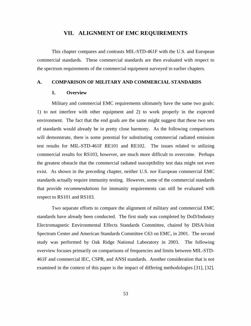
53
VII. ALIGNMENT OF EMC REQUIREMENTS
This chapter compares and contrasts MIL-STD-461F with the U.S. and European
commercial standards. These commercial standards are then evaluated with respect to
the spectrum requirements of the commercial equipment surveyed in earlier chapters.
A. COMPARISON OF MILITARY AND COMMERCIAL STANDARDS
1. Overview
Military and commercial EMC requirements ultimately have the same two goals:
1) to not interfere with other equipment and 2) to work properly in the expected
environment. The fact that the end goals are the same might suggest that these two sets
of standards would already be in pretty close harmony. As the following comparisons
will demonstrate, there is some potential for substituting commercial radiated emission
test results for MIL-STD-461F RE101 and RE102. The issues related to utilizing
commercial results for RS103, however, are much more difficult to overcome. Perhaps
the greatest obstacle that the commercial radiated susceptibility test data might not even
exist. As shown in the preceding chapter, neither U.S. nor European commercial EMC
standards actually require immunity testing. However, some of the commercial standards
that provide recommendations for immunity requirements can still be evaluated with
respect to RS101 and RS103.
Two separate efforts to compare the alignment of military and commercial EMC
standards have already been conducted. The first study was completed by DoD/Industry
Electromagnetic Environmental Effects Standards Committee, chaired by DISA/Joint
Spectrum Center and American Standards Committee C63 on EMC, in 2001. The second
study was performed by Oak Ridge National Laboratory in 2003. The following
overview focuses primarily on comparisons of frequencies and limits between MIL-STD-
461F and commercial IEC, CSPR, and ANSI standards. Another consideration that is not
examined in the context of this paper is the impact of differing methodologies [31], [32].
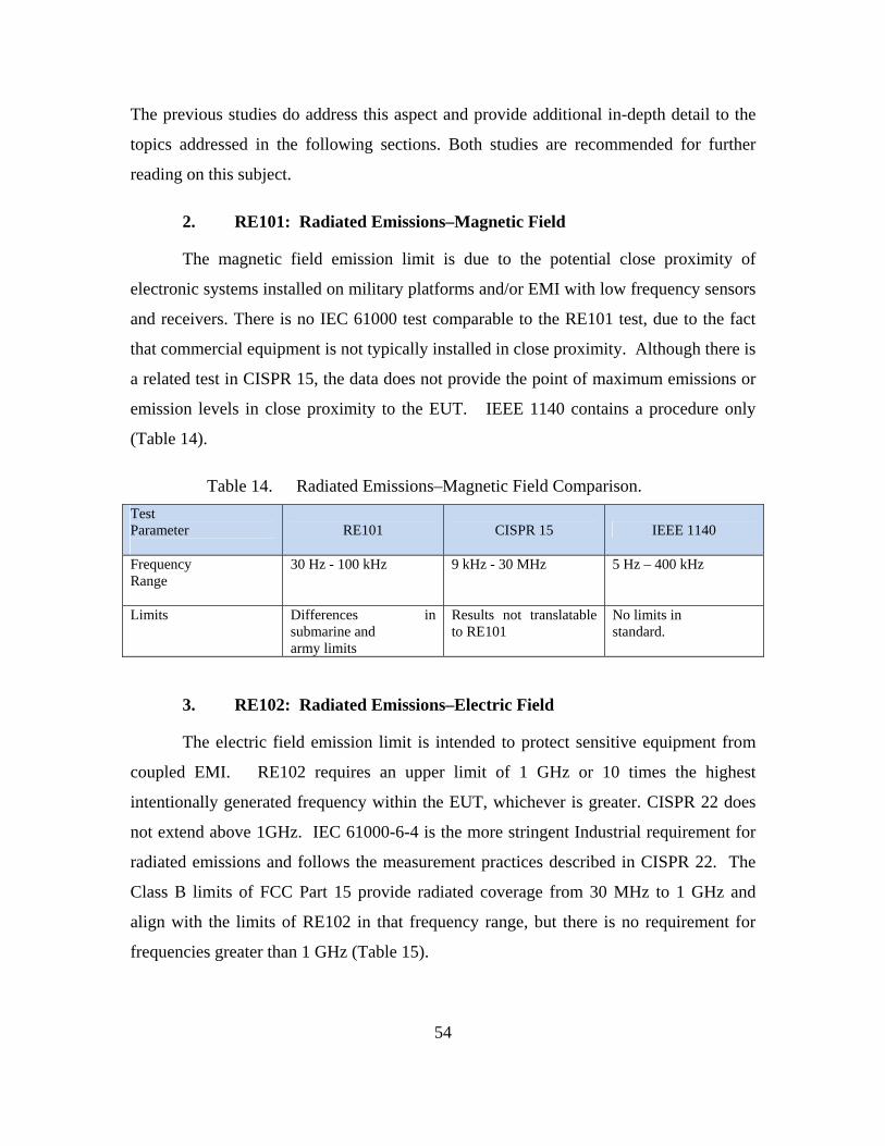
54
The previous studies do address this aspect and provide additional in-depth detail to the
topics addressed in the following sections. Both studies are recommended for further
reading on this subject.
2. RE101: Radiated Emissions–Magnetic Field
The magnetic field emission limit is due to the potential close proximity of
electronic systems installed on military platforms and/or EMI with low frequency sensors
and receivers. There is no IEC 61000 test comparable to the RE101 test, due to the fact
that commercial equipment is not typically installed in close proximity. Although there is
a related test in CISPR 15, the data does not provide the point of maximum emissions or
emission levels in close proximity to the EUT. IEEE 1140 contains a procedure only
(Table 14).
Table 14. Radiated Emissions–Magnetic Field Comparison.
Test Parameter
RE101 CISPR 15 IEEE 1140
Frequency Range
30 Hz - 100 kHz
9 kHz - 30 MHz 5 Hz – 400 kHz
Limits
Differences in submarine and army limits
Results not translatable to RE101
No limits in standard.
3. RE102: Radiated Emissions–Electric Field
The electric field emission limit is intended to protect sensitive equipment from
coupled EMI. RE102 requires an upper limit of 1 GHz or 10 times the highest
intentionally generated frequency within the EUT, whichever is greater. CISPR 22 does
not extend above 1GHz. IEC 61000-6-4 is the more stringent Industrial requirement for
radiated emissions and follows the measurement practices described in CISPR 22. The
Class B limits of FCC Part 15 provide radiated coverage from 30 MHz to 1 GHz and
align with the limits of RE102 in that frequency range, but there is no requirement for
frequencies greater than 1 GHz (Table 15).

55
Table 15. Radiated Emissions–Electric Field Comparison.
Test Parameter
RE 102 CISPR 11 CISPR 22 ANSI C63.4
Frequency Range
10 kHz – 18 GHz 150 kHz - 1 GHz & 11.7 - 12.7 GHz
30 MHz - 1 GHz 30 MHz - 1 GHz
Limits
severe at low frequencies external to vehicles
except for group 2, class A, no limits below 1 MHz
no limits below 30 MHz
CISPR (FCC) limits apply
4. RS101: Radiated Susceptibility–Magnetic Field
The magnetic field susceptibility limit is intended to ensure performance of
equipment is not degraded by low-frequency magnetic fields. Since the strength of
magnetic fields fall drastically over the space of a few inches, this aspect is only a key
factor where the magnetic source is in extremely close or extremely powerful, such as the
Electromagnetic Aircraft Launch System (EMALS). The RS101 commercial
counterparts are IEC 61000-4-8 (normal magnetic fields), IEC 61000-4-9 (magnetic
pulses), and IEC 61000-4-10 (damped oscillatory magnetic disturbances). Although the
frequency range of the IEC 61000-4 series is not as broad, the technical parameters of the
three documents in combination, are complementary to RS101 (Table 16).
Table 16. Radiated Susceptibility–Magnetic Field Comparison.
Test Parameter
RS101 IEC 61000-4-8, 9, 10
Frequency Range
30 Hz - 100 kHz 50 or 60 Hz
Limits
Navy & army limits differ
100 A/M
5. RS103: Radiated Susceptibility–Electric Field
The electric field susceptibility limit is intended to ensure that equipment will
operate without degradation in the presence of electromagnetic fields generated by
emitters in the represented environments. The commercial counterpart is IEC 61000-4-3,

56
which relates to the requirements for immunity of electrical and electronic equipment to
radiated electromagnetic energy. RS103 covers the frequency from 2 MHz to 40 GHz.
While IEC 61000-4-3 may cover from 26 MHz to a maximum of 1000 MHz, it is
normally applied only above 80 MHz. In addition to this discrepancy in frequencies, the
limits are compatible in only a select few military environments. IEC 61000-4-3
provides both a Residential (3 V/m) and an Industrial limit (10 V/m). RS103 applies to a
number of platforms and environment. The most benign of these environments would be
aligned with the IEC 61000-4-3 Industrial limit; however, the IEC standard would not be
suitable for the more stringent military environments that have a RS103 requirement of
200 V/m (Table 17).
Table 17. Radiated Susceptibility–Electric Field Comparison.
Test Parameter
RS103 IEC 61000-4-3 ANSI C63.12
(Severe Environment)
Frequency Range
2 MHz - 40 GHz 80 MHz - 1 GHz 26 MHz – 2.5 GHz
Limits
5 – 200 V/m 1 – 10 V/m 200 V/m
6. Summary
While IEC and MIL-STD-461 are not totally compatible, NAVSEA has been
invoking IEC standards since about 1995 on non-combat systems items. A very minimal
amount of EMI problems have occurred with COTS below deck. However, there are
many EMI susceptibility problems reported with COTS above deck. This observation is
consistent with the fact that commercial standards cite a 10 V/m worst-case environment.
As indicated by the requirements contained in MIL-STD-464A, the shipboard above deck
EME is much higher than this. In fact, even satisfying MIL-STD-461F requirements is
not sufficient to ensure proper functionality in the worst-case military environments; that
is why MIL-STD-464 was established in the first place. Although it might be possible in
some cases to utilize IEC testing in lieu of RE 101, RS 101, and perhaps even RE 102,
there is no way to accept commercial results in place of RS 103 for the vast majority of
situations. It might be possible to utilize this equipment in an enclosed metal space as the
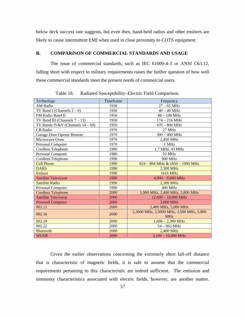
57
below deck success rate suggests, but even then, hand-held radios and other emitters are
likely to cause intermittent EMI when used in close proximity to COTS equipment.
B. COMPARISON OF COMMERCIAL STANDARDS AND USAGE
The issue of commercial standards, such as IEC 61000-4-3 or ANSI C63.12,
falling short with respect to military requirements raises the further question of how well
these commercial standards meet the present needs of commercial users.
Table 18. Radiated Susceptibility–Electric Field Comparison.
Technology Timeframe Frequency AM Radio 1930 27 – 65 MHz TV Band I (Channels 2 – 6) 1950 40 – 48 MHz FM Radio Band II 1950 88 – 108 MHz TV Band III (Channels 7 – 13) 1950 174 – 216 MHz TV Bands IV&V (Channels 14 – 69) 1950 470 – 806 MHz CB Radio 1970 27 MHz Garage Door Opener Remote 1970 300 – 400 MHz Microwave Oven 1970 2,450 MHz Personal Computer 1970 1 MHz Cordless Telephone 1980 1.7 MHz, 43 MHz Personal Computer 1980 10 MHz Cordless Telephone 1990 900 MHz Cell Phone 1990 824 – 894 MHz & 1850 – 1990 MHz DARS 1990 2,300 MHz Iridium 1990 1616 MHz Satellite Television 1990 4,000 – 8,000 MHz Satellite Radio 1990 2,300 MHz Personal Computer 1990 400 MHz Cordless Telephone 2000 1,900 MHz, 2,400 MHz, 5,800 MHz Satellite Television 2000 12,000 – 18,000 MHz Personal Computer 2000 3,000 MHz 802.11 2000 2,400 MHz, 5,000 MHz
802.16 2000 2,3000 MHz, 2,5000 MHz, 3,500 MHz, 5,800
MHz 802.20 2000 1,600 – 2,300 MHz 802.22 2000 54 – 862 MHz Bluetooth 2000 2,400 MHz WUSB 2000 3,100 – 10,000 MHz
Given the earlier observations concerning the extremely short fall-off distance
that is characteristic of magnetic fields, it is safe to assume that the commercial
requirements pertaining to this characteristic are indeed sufficient. The emission and
immunity characteristics associated with electric fields, however, are another matter.

Upon review, the IEC and ANSI standards for radiated electric field emissions and
immunity only require testing up to 1 GHz. These standards do acknowledge a need to
extend that range to 2 GHz, and ANSI C63.12 actually does extend its test requirement
up to 2.5 GHz. However, a review of even the short list of commercial technologies
covered in this paper (Table 18) will demonstrate that even at their time of publication,
these standards were not sufficient. Furthermore, when these data are plotted by
frequency use over the decades of their development, it becomes obvious that
commercial technology is on a rising exponential with regards to higher frequency levels
(Figure 13).
Figure 13. Plot of Commercial Frequency Use Over Time
As indicated by both WiMAX and WUSB technologies, commercial use of the
spectrum is steadily moving up into the 5–10 GHz range. Requirements in the existing
IEC and ANSI standards must be updated to reflect this growth. There is also the issue of
a lack of structured commercial validation for immunity. Immunity is expected, but up
58

59
until now, has been assumed to be present as a result of design considerations; actual test
validation has not been a requirement. Given the competitive demand for spectrum, this
approach is reaching a breakdown point.
C. COMPETING FOR RESOURCES
The ever-increasing use of mobile communications, broadcast media, and
wireless access has put huge pressure on the available spectrum. Regulatory authorities
are placing band allocations closer and closer together (Figure 14). These tighter
allocations increase the possibility of interference due to low power harmonic side band
transmissions. The fact that electronics are being designed to operate on lower and lower
voltages as a means of conserving battery power and reducing heat is also significant.
Circuits are now designed to operate on much lower currents and are, therefore, much
more susceptible to upset by the induced currents resulting from E3. The likelihood of
these effects being present is actually increased by the number of emitters that are
present.
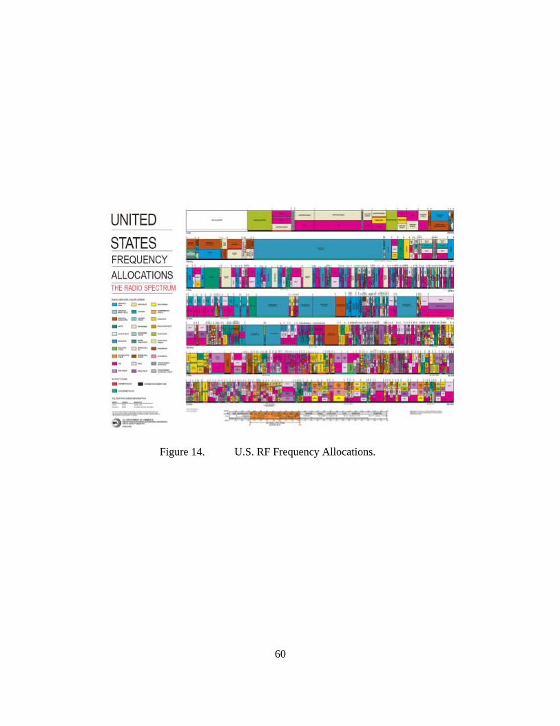
Figure 14. U.S. RF Frequency Allocations.
60

61
VIII. CONCLUSIONS
A. SUMMARY
After charting the development of RF devices over the past 100 years, it becomes
obvious that both DoD and commercial industry are on the rising edge of an exponential
curve for spectrum use. Unfortunately, spectrum is a limited resource. As designers and
manufactures develop new methods for squeezing every last bit of use out of the
available spectrum, new technologies are actually going to increase the likelihood of EMI
unless new approaches to EMC are adopted.
Because this technology is on the rise, it is critical that all EMC standards are
updated in a timely manner. According to Moore’s law, there is an 18-month turnover
for new technology, and we are definitely seeing five-year obsolescence. EMC standards
will need to be updated every five years if they are to keep pace with the technologies
they are supposed to regulate. When these standards are updated, it is crucial that their
requirements take into account the foreseeable needs of the future. This is the only way
that they can remain relevant for the span of their use.
With respect to the military’s technological needs, there is no way that the
military can avoid using COTS equipment—or at least commercial technologies. With
an estimated eight-year timeframe for the development and deployment of new
equipment, DoD must be able to leverage products that are already available to
consumers. Unfortunately, one of the realities of this situation is that this equipment
must be tested for EMC. As shown in this report, current emission standards cover only
up to 2.5 GHz at best, and there are NO requirements for commercial susceptibility
testing. In commercial manufacturing, where pennies saved add up to millions of
dollars, the very corners that are cut also reduce the overall robustness of the product with
respect to EMI. To introduce these devices into a military EME that is often magnitudes
harsher than the environment these devices were minimally designed for, and expect
them to perform a mission-critical task, is just an invitation for disaster.

62
Commercial needs, however, are actually converging with military needs.
Although new technologies, such as cognitive radios and DSA, might ultimately ease
many of the issues related to spectrum management, these approaches do not address
issues related to E3. In order to maximize battery power and frequency usage, the
operational voltages of commercial devices is getting lower and lower, making them
more susceptible to E3 induced current. At the same time, we no longer live in the benign
EM environment of the 1950s, 1980s, or even 2001 (when most of the current EMC
standards were published). The ambient EME is an additive effect that increases along
with the number of devices that create it. Given the exponential increase in emitting
devices, combined with the fact that these same devices are more likely to be susceptible,
we are reaching a point at which E3 effects are going to be a greater problem at the
consumer level. Commercial manufacturers will also have to take new measures to
ensure proper functionality of their products. These measures need to include better
design with respect to preventing EMI and increased frequency requirements for
emission testing along with mandatory susceptibility testing.
B. KEY POINTS AND RECOMMENDATIONS
1. Military and commercial EMC standards need to be updated every five
years to keep pace with technology
2. DoD must test or require system integrators to test major systems that use
COTS to ensure EMC in the expected EME.
a. Perform radiated susceptibility testing on COTS equipment,
particularly if it is being used in a critical function
b. Perform additional radiated emissions testing between 1–18 GHz
on COTS items placed in critical areas
3. Military Program Offices need to incorporate item 2 into their budgets and
schedules
4. Standardize the selection and decision making process for military use of
COTS equipment
63
a. Military should create “use cases” that will allow for blanket use of
business class equipment
5. Commercial standards need to further categorize equipment and
incorporate immunity requirements based on these classifications
a. Immunity should be required for business and/or critical systems
b. Immunity should be required for devices that are more likely to be
operated in a higher EME
c. Immunity should not be required for nonessential devices such as
toys
6. Commercial standards need to extend frequency ranges for testing of
radiated emissions, electric field
a. Threshold: 150 KHz – 6 GHz
b. Objective: 10 kHz – 10 GHz
7. Commercial standards need to extend frequency ranges for test of radiated
susceptibility, electric field
a. Threshold: 2 MHz–6 GHz
b. Objective: 2 MHz–10 GHz
C. AREAS FOR FUTURE EFFORT
My intention was to provide recommended commercial limits for radiated
susceptibility; however, it is necessary to first perform an updated assessment of the
present ambient EME. Figure 15 is a graphical representation of this data taken from
ANSI C63.12. This plot illustrates the various EMEs levels expected in a variety of
environments circa 1999. A similar study should be conducted to determine equivalent
levels in 2010.
Based on the results of this study, a determination for a recommended commercial
immunity level should be derived. These requirements for immunity should then be
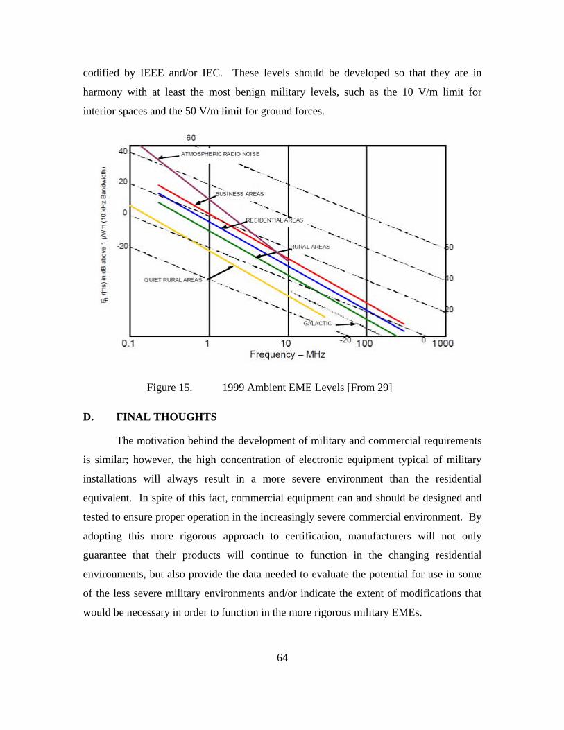
codified by IEEE and/or IEC. These levels should be developed so that they are in
harmony with at least the most benign military levels, such as the 10 V/m limit for
interior spaces and the 50 V/m limit for ground forces.
Figure 15. 1999 Ambient EME Levels [From 29]
D. FINAL THOUGHTS
The motivation behind the development of military and commercial requirements
is similar; however, the high concentration of electronic equipment typical of military
installations will always result in a more severe environment than the residential
equivalent. In spite of this fact, commercial equipment can and should be designed and
tested to ensure proper operation in the increasingly severe commercial environment. By
adopting this more rigorous approach to certification, manufacturers will not only
guarantee that their products will continue to function in the changing residential
environments, but also provide the data needed to evaluate the potential for use in some
of the less severe military environments and/or indicate the extent of modifications that
would be necessary in order to function in the more rigorous military EMEs.
64

65
LIST OF REFERENCES
[1] C. Verwoert, “What is electromagnetic interference? - Definition from Whatis.com—see also: EMI,” SearchMobileComputing.com, downloaded July 2009 from < http:// searchmobilecomputing.techtarget.com/ sDefinition/0,,sid40_gci213940,00.html>.
[2] C.R. Paul, Introduction to Electromagnetic Compatibility. Wiley-Interscience, New York, 2006.
[3] Christopher Sterling, Military Communications: From Ancient Times to the 21st Century. ABC-CLIO, Santa Barbara, 2007.
[4] T. Hubing and A. Orlandi, “A Brief History of EMC Education,” 16th International Zurich Symposium and Technical Exhibition on EMC, 2005, pp. 95–98.
[5] J. Stine and D. Portigal, "Spectrum 101," MITRE Technical Report: MTR 04W0000048, 2004.
[6] D.M. Pozar, Microwave Engineering. Addison-Wesley Publishing Company, Boston, 1993.
[7] C.A. Balanis, Antenna Theory. John Wiley and Sons Inc., New York, 2003.
[8] H. Slotten, Radio and Television Regulation: Broadcast Technology in the United States 1920–1960.Johns Hopkins University Press, Baltimore, 2000.
[9] C. R. S., “EMC History - Electromagnetic Compatibility,” Analab.com, downloaded August 2009 from < http://www.analab1.com/emc.html>.
[10] “Military Communication: World War II and After — Britannica Online Encyclopedia,” Encyclopedia Britannica, downloaded June 2009 from < http:// www.britannica.com/EBchecked/topic/382324/military-communication/57557/World-War-II-and-after>.
[11] W. Kesselman and H. Mertel, “History of Military EMC Specifications,” IEEE EMC Online, downloaded July 2009 from < http://www.c63.org/ documents/c63/newsletters/ 2000_07_c63_newsletter.htm>
[12] Paul, C.R. “Celebrating Our Past; Preparing for the Future,”IEEE.org, downloaded June 2009 from < http:// www.emcs.org/acstrial/newsletters/winter07/history.pdf>
[13] “FCC Public Notice DA 05-424,” February 2005.
66
[14] R. Carlisle, Scientific American Inventions and Discoveries : All the Milestones in Ingenuity From the Discovery of Fire to the Invention of the Microwave Oven. Wiley, New York, 2004.
[15] O. Linzmayer, Apple Confidential 2.0: The Definitive History of the World's Most Colorful Company. No Starch Press, San Francisco, 2004.
[16] J. Hanson, 24/7: How Cell Phones and the Internet Change the Way We Live, Work, and Play. Praeger, Westport, 2007.
[17] B.Z. Kobb, Wireless Spectrum Finder, Telecommunications, Government and Scientific Radio Frequency Allocations in the U.S. 30 MHz - 300 GHz. McGraw-Hill, New York, 2001.
[18] D. Martin, Communication Satellites. The Aerospace Press, Los Angeles, 2000.
[19] M. Gast, 802.11 Wireless Networks: The Definitive Guide, Second Edition. O'Reilly Media, Inc., Cambridge, 2005.
[20] “Wireless USB at AllExperts,” AllExperts.com, downloaded July 2009 from < http://en.allexperts.com /e/w/wi/wireless_usb.htm>
[21] P. Robinson, The CNN Effect: The Myth of News Media, Foreign Policy and Intervention. Routledge, New York, 2002.
[22] “MIL-STD-461F: Department of Defense Interface Standard Requirements for the Control of Electromagnetic Interference Characteristics of Subsystems and Equipment,” December 2007.
[23] “MIL-STD-464A: Department of Defense Interface Standard Electromagnetic Environmental Effects Requirements for Systems,” December 2002.
[24] “Electromagnetic Compatibility: The Role and Contribution of IEC Standards,” International Electrotechnical Commission, Geneva, 1999.
[25] R. Gubisch, “Inside FCC Part 15 and Canada's Corresponding Standards,” Compliance Engineering, downloaded June 2009 from < http://www.ce-mag.com/99ARG/Gubish31.html>
[26] “Code of Federal Regulations, Title 47 - Telecommunication: Part 15,” July 2009.
[27] “ARRLWeb: RFI - Regulatory Information,” ARRL Web, downloaded August 2009 from < http:// www.arrl.org/arrlletter/98/980529/>
[28] “Code of Federal Regulations, Title 47 - Telecommunication: Part 18,” July 2009.
[29] “Code of Federal Regulations, Title 47 - Telecommunication: Part 95,” July 2009.

67
[30] “ANSI C63.12-1999 American National Standard Recommended Practice for Electromagnetic Compatibility Limits,” March 2000.
[31] “Engineering Practice Study March 2, 2001 Results Of Detailed Comparisons Of Individual EMC Requirements And Test Procedures Delineated In Major National And International Commercial Standards With Military Standard MIL-STD-461E,” DoD/Industry Electromagnetic Environmental Effects Standards Committee, March 2001.
[32] P.D Ewing and R.T. Wood, “Comparison of U.S. Military and International Electromagnetic Compatibility Guidance,” Oak Ridge National Laboratory, August 2003.

68
THIS PAGE INTENTIONALLY LEFT BLANK
69
INITIAL DISTRIBUTION LIST
1. Defense Technical Information Center Ft. Belvoir, Virginia
2. Dudley Knox Library Naval Postgraduate School Monterey, California
3. Mr. Carl Siel ASN (RD&A) Chief Systems Engineer Washington, D.C.
4. Ms. Patricia Hamburger Director, SEA 05H, HSI and Warfare Systems Engineering Naval Sea Systems Command Washington, D.C.
5. Mr. Dave Goldberg Director, SEA 05H3 Naval Sea Systems Command Washington, D.C.
6. Mr. D. Mark Johnson SEA 05H3 Director, Force E3 and Spectrum Management Office Washington, D.C.