nava anoup - defense technical information center · descriptions of experiments and discussion of...
TRANSCRIPT

DOCUMENT CONTROL DATA - R&D(SaOurtlY classification of 1111s. bi)' of abstoeot MWd indoximi annotation must be enter"d when eh. overall rapurt is ciaeatilisd)
I ORGINTING ACIVIY (omor~iirutor)2a. REPORT SECURITY C LASSIFICATION
NAVAL AIR P. ?OPTJIS::O TFST CENTER (AE) UNCLASSIFI EDNAVA 13;,SF2b anouP
Rotor Burst, Protection 'rograrn - Phases VI and VII:' Exploratory Experimentationto Provide Data3 for- thc Design of' Rotor Burst Fragment Containment Rings
4. DESCRIPTIVE NOTES (TMpe of repoi' and Inclusive dot".)
Phase Report57 AUTHOR(S) (L~ast n.n,, first nitme, 1,-tloR)
. REPORT DATE 7.TTLN.O AE
March_1972 7_NO._rMar
ea. CONTRACT OR GRANT NO 98. ORIS1161ATOR's RECPORT NUMBIERS)
b. PROJWCT NO. NASA DPH C--J 1581-B and NAPTC-AED-1968C-1,153:-B, ) d
c. 910. ~Tmen rftxT NO(S) fAnyo.b',.imab.,e tmatimay beaseatind
d.
10. A V AIL ABILITY /LIMITATION NOT'ChK
Distribution of this re;Dor-ý is un~limited.
11. SUPPLEMENTARY NOTES Ia. SPONSORING MILITANY ACTIVITY
Department of the NavyNaval Air Systems Conmand
13. ABSTRACT
Presented are the resuLts of exploratory experimentation that was conducted inNAPTC Rotor Spin Facil~i-ty to provide criteria for the design of turbomachinerotor burst fragment cfntainment rings. High-speed photography was used tostudy containment proc:!sses involving freely Lupported rings of differentmaterials and a variety of rotor and flat disk fragments.(
D D I JAN 6.1473 *UNCLASSIFTEDSecurity Classification

NAPTC-AED-19(.8
TABLE OF CONTENTS
TITLE PAGE N1O.LIST OF FIGURES . .. .. .. .. .. .. .. .. ... . .. . . .i
INTRODUCTION . ... .. .. . . . . . ....... ... 1
CONCLUSIONS . ..... ...... . .......... . - 2
RECOMMENDATIONS . . . . .. . ....... . . ... . 3
DESCRIPTIONS OF EXPERIMENTS AND DISCUSSION OF RESULTS......... 3 - 9!!- EVALUATION OF CONTAINMENT .. .. .. .. .. ..... . .. . 3 - 5
- ROTOR BLADE CONTAINMENT .............. *. .. .
- FLAT DISKS . . . . . . . . . . . . . . . . ........... 7
- FRAGMENT NUMBER ..... ............. . . . . . . . . . . 7
- ROTOR FRAGMENT DEFLECTION'DEVICES . ............ 7 - 9
* - THE INCIDENCE OF UNCONTAINED ROTOR BURSTS ...... ..... 9
METHOD OF EXPERIMENT . . . ............ . . . . . .. 9 - 10
REFERENCES ...... ................. .. .... . . . . II
TABLE i . . . . . . . . . . . ................ 22-16
TABLE II ................ .. 17FIGURES 1 TO 19 ............... . ". . 18 - 36
APPENDIX A: PROGRAM FOR THE DEVELOPMENT OF ROTOR BURST FRAGMENTCONTAINMENT RING DESIGN CRITERIA . . . . . . . . . . . . . . ... . Al - A-5
ACKNOWLEDGEMENTS ...... . . . . . ...... . . . . . 37
ABSTRACT CARD
DOCUMENT CONTROL DATA -R&D- DD FORM 1473
-Ib

NAPTC-AED-196(-
LIST OF FIGURES
FIGURE TITLE PAGE NO.
1 Rotor and Blade Modification 18
2 3-Fragment Rotor Burst Into a 4130 19Steel Ring
3 3-Fragment Rotor Burst Into a TRIP 20Steel Ring
4 3-Fragment Rotor Burst Into a 2024-T 4 21Alumrinum Ring
5 3-Fragment Rotor Burst Into a Ballistic 22Nylon With Steel Liner Ring
6 3-Fragment Rotor Burst Into a F.lament 23Wound Fiberglass Ring
7 Single Blade Burst Into a 6061-T 6 24Aluminum Ring
8 Rotor Blade Into A 6061-T 6 Aluminum Ring 25
9 3-Fragment Disk Burst Into a 4130 Steel 26Ring
* 10 3-Fragment Flat Disk Burst Into a 2024-T4 27Aluminum Ring
11 2-Fragment Rotor Burst Into A 4130 Steel 28Ring
12 3-Fragment Rotor Burst Into a 4130 Steel 29Ring
13 4-Fragment Rotor Burst Into a 4130 Steel 30Ring
14 6-Fragment Rotor Burst Into a 4130 Steel 31Ring
15 2-Fragment Rotor Burst Into Rigidly Attached 32Steel Half Rings
16 2-Fragment Rotor Burst Into Freely Supported 33Steel Half Rings
-oiC.

NAPTC-AED-1968
LIST OF FIGURES (CONT'D)
FIGURE TITLE PAGE NO.
17 Naval Air Propulsion Test Center Rotor 34hSpin Facility
18 Typical Potor Burst Containment Experiment 35Set-Up
19 The Incidence of Uncontained. Rotor Bursts 36In Commercial Aviation
ii
1.
i _____ ______

NAPTC-AED-1968
INTRODUCTION
1. This is the final report on Phases VI and VII of the Rotor Burst ProtectionProgram (RBPP) which is being conducted by the Naval Air Propulsion Test Center.W(NAPTC) under the auspices of the National Aeronautics and Space Administrationtl)(NASA).
2. The program was started when •n investigation made by NAPTC for the NASACommittee on Aeronautical Systems(2) (reference a) revealed thit commercialjet aircraft were experiencing uncontained engine rotor bursts-) at a signifi-cant yearly rate. This investigation also disclosed that uncontained rotorbursts continued to occur at a relatively constant yearly rate even though otheraircraft operational problems were responding favorably to the improvements andadvancements being made in applicable technology. The persistence of the rotorburst problem seemed to indicate that an upper limit of rotor reliability hadbeen reached; a limit not necessarily dictatei by technology, but one that re-flected the compromises in absolute reliability that are made in order to makecommercial flight economically feasible. It appeared as though an irreduciblenumber of rotor bursts would occur each year; Because of the catastrophicconsequences that can be associated with such events, it was decided thatpositive methods of providing for passenger safety would have to be developedand employed to protect the passengers and vulnerable parts of the aircraft fromthe lethal and devastating high energy fragments that are generated by an uncon-tained rotor burst. In response to this decision to provide protection, theRBPP was established at NAPTC by NASA. The goal of this program is to developand provide criteria for the design of flight-weight devices that can be usedon jet powered aircraft to protect people and equipment from gas turbine enginerotor burst fragments.
3. Reports that document the development of this program and which presentpreliminary experimental results have been published by NAPTC; these are listedas references a, b, c and d.
4. This report presents the results of exploratory experiments that were con-ducted at NAPTC to provide information and data for the design of rotor frag-ment containment devices. It also contains an up-date of the statistics onthe occurrence of jet engine rotor bursts in commercial aviation.
CONCLUSIONS
5. Regarding the rotor burst fragment containmeit process:
a. In a containment situation involving fragments from a typical axialflow turbomachine rotor, blade deformation constitutes almost all of the fragment
(1) Contract No. DPR C41581-B, Modifications 1 and 2.(2) Formerly the NASA Advisory Committee on Aircraft Operating Problems.(3) An uncontained rotor burst is defined as a rotor failure that producesfragments which penetrate and escape the confines of the engine casing.

I I+
NAPTC-AED-1968
deformation that occurs; the hub or disk portion of the fragment behaves as arigid non-deformable body that causes distortion of the containment ring. Theforces needed to deform the blades are relatively small as are the energiesabsorbed by their deformation. Therefore, the blades on a rotor fragment donot significantly influence the distribution of the impact loads that are in-duced in a ring (provided the ring thickness approaches that required to effectcontainment and the fragment hub to blades mass ratio is large), nor do the bladesabsorb significant amounts of energy through their deformation during the con-tainment process. The blades serve only to influence the fragment trajectoryduring the initial stages of impact. 'This also means that -n cases where therotor tip-to-ring clearance is small (test or operational clearances) the bladeradial length becomes in effect the radial. clearance that influences the orien-tation of the hub or disk portion of the fragment..
b. The amount of blade deformation sustained by the rotor fragments duringcontainment appears to be independent of the hardness of the containment ringmaterial. At equivalent burst speeds soft and hard materials alike cause thesame type and degree of blade deformation.
c. The general displacement and deformation cnarazteristics of containmentrings,optimally desig. 'd for weight reduction and subjected to rotor fragmentattack, do not significantly vary for rings made from materials having a widerange of strengths aud ductilities. The ring distorts to conform to the shapeof the undeformed disk portion of the rotor fragment. The number of ring dis-tortion sites is equal to twice the number of fragments attacking the con-tainment ring. The magnitude of ring distortion, and the time it takes forthes. distortions to develop depends on the ring mass, material strength, thick-ness or stiffness, and the speed of the fragments at impact.
d. The variables that appear to affect the containment processs most signifi-cantly are:
(1) The burst speed(2) The number of fragments(3) The blade tip-to-hub diameter ratio of the rotor fragments(4) The ring length-to-thickness ratio(5) The ring diameter(6) The ring material
6. Regar1ing Rotor Burst Fragment Deflection:
Rotcr fragments can be effectively deflected (their trajectories controlled)through the use of partial rings of reasonable weight.
7. Regarding the problem of jet engine rotor bursts in commercial aviation:
The rate of rotor bursts increased to approximately 31 bursts peryear for the years 1969 and 1970. Because of the potentially catastrophic conse-quences of such events, this level of incidence of rotor bursts is consideredhigh.
2

NAPTC-AED-1968
RECM0 7DATIONS
8. The ,program of -systematic rotor burst -containment experimentation outlinedin Appendix A and now being conducted- at the NAPTC should be continued tocompletion. This program was developed to provide data for the design ofoptimum weight rings that will contain the fragments from various size axialflow turbomachine rotors that burst at oir near their operating design speed.
9. Experimental and analytical efforts to investigate the concept of partialshielding, or more. aptly, rotor burst fragment deflection, should continue.Systematic approaches are being developed at NAPTC to experimentally producecriteria for the design of optimum weight rotor fragmdfht deflection devicesthat will provide regions of protection from fragment attack.
DESCRIPTION OF EXPERIMENTS AND DISCUSSION OF RESULTS
10. Table I lists the rotor, disk and blade burst containment experimentsthat were conducted during Phases VI, and VII and part of VIII of the RBPP;it also briefly describes the hardware, materials ard conditions involved ineach experiment. These experiments were considered exploratory because theywere conducted to learn something about the nature of the rotor burst contain-ment process and to establish what variables significantly influence or char-acterize the dynamics and deformations involved in rotor burst containment.Because of their variety, the best way to describe the experiments conductedand discuss their results is to group and present them according to theirobjectives.
EVALUATION OF CONTAINNENT RING MATERIALS AND ROTOR FRAGNENT BEHAVIOR
11. These experiments involved subjecting rings of equal weight, but madefrom different materials having varied mechanical properties, to turbine rotorfragment attack. The objectives were to:
a. Determine what effect differences in material mechanical propertieshad on the characteristics of fragment and ring deformation.
b. Comparatively evaluate the fragment containment capabilities of thevarious materials used.
c. Evaluate a fragment containment ring design concept commonly calledthe strain energy method that enjoys widespread use in industry. This concept isexpressed in equation form:
(1) WR = KEB
f((,, e)
3
I: . . . . .

NAPTC-AED-1968
Wnich in stated form says, that the weight of a ring (WR) needed to--conta-inrotor burst fragments can be estimated by dividing the total fragment energy(rotor energy at burst KEB) by thearea under the engineering stress-straincurvelf6) for the ring-material used' where p- ring material density
Ef = ultimate strain, f (0, e) = function of engineering stress and strain.
12. For these experJiments GE T58 engine power turbine rotors modified toburst into three equal pie sector fragments (as shown in Figure 1) were usedas fragment generators. For each type of ring maierial studied, the burstspeed and therefore the fragment attack energy was increased incrementallyfrom experiment to ex,:eriment until ring failure occurred. The dynamics anddeformation characteristics of the containment process involved in theseexperiments were recorded by high-speed .ph9tpgoaphy.• Yigures 2 through-6,
show selected frames from high-speed photographic sequences taken of 4130 steel,TRIP steel, 2024 (T4 ) aluminum, ballistic nylon and filament wound E glass ringsin the process of contz.ining rotor burst fragments. These photographic resultsshow that the gross ring and fragment deformations are approximately the samefor all the ring materials tested. The rotor fragments experienced deformationsinvolving only the blades which were curled and bent while the disk portioh ofthe fragment remained intact and suffered no apparent deformation. Fra~me toframe analysis of the fragment displacements recorded by the high-speed photo-graphs revealed that the time that it took blade deformations to C.ccur wasapproximately the same regardless- of the ring material used and varied only withburst speedz Blade deformation times became shorter as burst speed was increased.
The rings were displaced and deformed to generate the typical three lobedpattern associated with 3-fragment bursts; this is well illustrated in thehigh-speed photographs.
In all cases large displacements and deformations of the Hing did not occuruntil fragment olade deformation was almost completed. This indicated thatrelatively small forces are generated by the blade deformation which occursduring the initial stages of containment. These results qualitatively confirmthe results of single blade deformation analyses and experiments that were con-ducted by the Massachusetts Institute of Technology (NIT). The findings of the MITinvestigation also indicated that the forces and energy needed to deform ablade,as it '?haracteristically would during the containment process,were rela-tively small (approximately 500 in-lb of energy per blade), Based on thesecombined results some important observations can be made:
a. The rotor fragment blades in their deformation do not substantiallyabsorb much of the fragment energy that must be dissipated during cc;tainment.
b. The blades by virtue of their length and mass distribution -- rVe cnlyto prescribe the location of the fragment center of mass and the iadiai 5.stancethrough which the non-deformable hub mass must travel during the Initzal stnof containment. These factcrs influence the trajectory and orientation of the
4

NAPTC-AED-!968
fragment during the latter stages of containment when poriounced• ring displace-ments and stresses (deformatiot's) are induced.
.c Because the blades deform -so readily, radial clearance e,. ects areminimized. Differences -in rotor-to-casing radial clearances between experimentand actual turbomachine construction are small pompared to the blade length.Therefore, the ring and fragment behavior observed during -xperiments usingradial clearances as large as 0.5 inches would be representative of the behaviorthat could be expected in an engine where rotor-to-casing clearances are mea-sured in thousandths of an inch.
"13. A comparison of the fragment energy containment capability of the variousrings tested is presented in Table II. The factor used to make this comparisonis called the specific contained fragment energy (SCFE). This factor,whichprovides a measure of ring capability, is derived by dividing the frngmentenergy that was contained by the weight of the ring required to provide contain-ment.
The comparisor indicates that TRIP steel has the greatest containm'ntcapability of s> i he ring materials tested. However, it should be noted thatthese results s=r on..y indicative of the actual containment capabilities ofthe ring matortals tested. Daring each of these experiments, the high-speedphotographs revealed that the fragments were escaping the confines of the ring.The zpeed.or more aptly, the amount -of residual energy with which a fragmentescaped ,h;' ring depended on the deformation characteristics of the ring, whichin turn was dependent on the mechaaical properties of the ring material. Sincematerials having varied mechanical properties were used in these tests, it islogical to assume that the fragments escaped with varying amounts of residualenergy depending on the ring material used.. The prime objective of theseexperiments was to observe and record the fragment-ring interactions throughthe use of high-speed photography. To do this no obstructions could be placedat the ring ends to prevent axial escape of the fragments. The behavioralcharacteristics of both the fragments and ring materials have been well docu-mented during this phase of exploratory experimentation; therefore, future testsmade to evaluate the containment capabilities of various materials will be de-signed to prevent axial escape of the fragments..
14. Based on the analysis presented in paragraph ll.c. involving the areaunder the engineering stress-strain curve, the energy absorbing potential ofa 7-lb. 4130 steel ring (having an axial length of lJ inches and an internaldiameter of 15 inches) -'uld be approximately 247800 in-lb. However, experi-mental results indicate tnat such a ring is capable of containing rotor frag-m ents having three times this amount of energy. This indicates that contain-ment ring design analyses based on this concept of strain energy tend to be tooo'onservative and would not provide the optimum weight ring designs that arer•eing sought for aircraft applications. The analysis is not sophisticatederough to take into account the many other mechanisms of energy dissipationsuch as heat, mechanical displacement, etc. that are associated with the rotorfregrnent containment process.
5

NAPTC-AED-1968
ROTOR BLADE CONTAINNENT,:
15. In these experiments, blades from GE T58 engine power turbine rotorswere modified to fail and impact p9nrtainment rings m'de -from -6061 ('t6) and2024 (T4) aluminum. These materials were selec6ted' because they were readilyavai.able and have mechanical properties that are well khoin at high ratesof strain. Two types of rotor blade containment bxptcrimehts of interest wereconducted.
a. Single blade bursts in which one blade mounted on a rotor disk wasmodified to fail and produce a blade fragment.
b. Single blade bursts"in which one blade in a fully bladed rotor wasmodified to fail.
16. These blade burst experiments were conducted to:
a. Study the blade and ring interactions and deformations during thecontainment process.
b. Record (by high-speed photography) and measuire the 'ring displacementswith respect to time. These motion data were to be used by NiT in their TEJ-2computer program to obtain estimates of the force-time dharacteristics of theblade during the containment process. Reference contains details of thisTES-2 computer program.
c. The experiments in which one blade in a rotor was modified to failwere conducted to study the blade fragment and blade interactions and throughcomparison with isolated blade experiments determine what effcct these inter-actions had on the containment process.
17. The results of representative blade-fragment containment experiments,which are in the form of high-speed photographs, are shown in Figures 7 and 8.
Figure 7 depicts the sequence of events that occur when an isolated bladeis contained by a freely supported ring whose thickness is representative ofan engine casing. The ring deformation is seen to be local and extensive.The blade was deformed in a curling manner characteristic of turbine blades.This is shown in the post test photograph of Figure 7. Figure 8 shows thesequence of events that occur when a blade from a rotor fa-ils, impacts a casing,and interacts with the blades remaining on the rotor. Initially ring defor-mation resrables that produced by-the isolated nlade burst. this is reasonablebecause the rings used and the b irst speeds are the same for each experiment.But as time progresses, incheasing interaction of the blade fragment with theother blades is observed and a failure of the ring occurs. This comparisonipnersactiden an csearle andiates fothatl e omengu oimrps arTe inducmparisoprovides evidence that greater forces and energy transers are e by bladefragment by other blades in the rotor adds measurably to its destructive potential.This imparted energy or momentum must be considered in any design analysis for
6

NAPTC-AED-1968
blade containmenit rings or engine casings.
FLAT DISKS
18. The use of flat disks as. fragment, generators was •explored during theearlier phases of containment experimentation. It was thoughtthat they mightbe employed at less expense to si ulate turbv 'achine rotor fragments. IHowever,after some experimentation it became apparp -. that they would not serve thispurpose. The type of loading imposed on a rAng by a flat disk fragment wasfar different than that of a bladed rotor iragment. This is shown in Figures2, 9 and 10 which contain high-speed photo sequences from flat-disk and bladed-rotor containment experiments. Although flat disk fragments are not applicableas rotor fragment simulators, the results of several experiments, in which attenptswere made to 'conta'in 3-fragment flat disk bursts at various speeds using alu=-inum and steel rings, are presented in Table III. *These data would be usefulfor the design of flywheel fragment containment rings.
FRAGMENT NUMBER
19. Containment experiments were conducted in which GE T58 engine power turbinerotors were modified to generate 2, 3, 4 and 6 symmetrical pie-sector shapedrotor fragments. Rings made from. 4130 steel and having the same size and weightwere used as containment devices. These experiments were conducted to determinewhat effect the number of rotor fragments had on the containment capability ofthe ring, or from another perspective, what ntmber of fragments constituted theworst type of fragment attack condition for a containment ring. The results olthese experiments (high-speed photographs) are shown in Figures 11 thru 14..The rings deformed symmetrically to form twice as many lobes as there were num-ber of fragments involved in the attack. Too few experiments were conductcd todraw any conclusions as to what number of fragments represented the worst impactcondition. However, this will be studied more extensively during the next pheseof investigation.
ROTOR FRAGMENT DEFLECTION DEVICES
20. Protecting an aircraft from rotor fragment attack through the use of partialrings, which would serve to redirect fragment to less sensitive and vulnerableareas of the aircraft, is an attractive concept, since it promises considerableweight savings over complete ring systems which are designed to capture or containthe fragments. Two significant experiments have been conducted to examine thefeasibility of this concept and to study the mechanics that are involved in thedeflection process. For the first experiment (120), two half-rings of equalsize and weight were installed around a GE T58 engine power turbine that wasmodified to burst in half (refer pretest photo in Figure 15). One half-ring
* was welded to a rigid mount at one end; the other end was free of any attach-ment (hinged section). The other half-ring was welded to rigid mounts at bothends (fixed). This arrangement made it possible to observe and evaluate thebehavior of two different deflection ring configurations during one experiment.
7

ITAPTC-AED-1968
The objectives of this experiment were to- examine the feasibility of usinga half-ring to control the trajectory of a rotor fragment and to establ~ishwhat method of half-ring attachment would be most effective for fragment-deflection purposes. Selected high-speed photographs taken during the experi-ment are presented in Figure 15. They show. that the rotor fragments impacted
the half-rings close to their points of attachment; this impact condition wasconsidered to be the worst pbs~ible, and therefore, provided a, rigorous testof how well the half-rings ftuctioned as fragment deflection devices.
The fixed half-ring experienced failures near' the points of attachmentsoon after impact. The fragment did not, as might be expected, enter the"protected region" as a result of these failuies. Instead the fragment con-tinued to interact with the freed ring section and moved along what could beconsidered a safe trajectory.
The "hinged" half-ring behaved as anticipated: A plastic hinge formedclose to the attachment point at impact. The half-ring pivoted about thispoint, while it guided the fragment over its inner surface along a -safe, con-trolled trajectory away from the protected region.
The mounts for botb half-rings failed during the fragment interaction.The results of this experiment demonstrate conclusively that half-rings canbe used to provide suitable fragment trajectory control or deflection.Howeve~the "hinged" half-ring appeared to function more effectively. In
addition, it represented a lower weight -.ess complex cohfiguratiozi. Thesecond experiment (123) was similar to the first involving the same type of
modified rotor and two steel half-rings. However, the half-rings were ofdifferent weight (one weighing approximately twice the other), and they werefreely suspended rather than being fixed at one or both of their end points.The objective of this experimept was to determine if the inertia of a half-ring alone would provide the constraint needed to control the fragment tra-jectory. The half-ring weights were different to provide different inertialresponses to impact. Selected high-speed photographs of this experiment arepresented in Figure 16. They show that the frAgmehts struck the half-ringsat points considered to be optimal for the evaluation of their trajectorycontrol capabilities.
The lighter or thinner of the two half-rings (b th half-rings had thesame internal diameter and axial length) deformed considerably during the
impact process and offered almost negligible resistanrm to fragment trans-lational motion. As a result the fragment moved with considerable energyinto the region that was to be protected by the half-ring.
The heavier half-ring was also' deformed during impact but not to thesame extent as the thin half-ring. Fragment translational motion was some-what arrested as a result of the interaction, but the course of the fragmentwas not controlled. Like the other fragment, it too moved into the region to
8
I

HILPIM-AED-1968
be protected. The behavior of both the fragment and half-ring after defornationwas like that associated with the elastic collision of stationayj and novingmasses; iwhere the mass with the initial momentum becommes stationary and thestationary mass is adcelerated as a result of thit col~ision. The results ofthese experiments indicate that a detailed experizental study to deter-minethe effect of the following viiables on the fragment deflection process wouldyield data -pertindnt to the -deieiopmeht -of criteria for the design of optuweight rotor fragment deflection devices:
a. Ring material.b. The partial ring size: I.D., thickness, axial length and arc length.c. The ring constraints.d. The point at which the fragment impacts the ring relative to its
point of constraint.
THE INCIDENCE OF UNCONTAINED ROTOR BURSTS
21. Figure 19 shows the yearly incidence of uncontained jet engine rotorbursts in commercial aviation for the past nine years (1962 to 1970). Daringthe past two years (1969 and 1970) an increase (over double those experiencedin 1968) to an average of 31 uncontained rotor burst per year has been realized.The threat that these occurrences present to the welfare of cor,,ercial airtravelers is still a vital and major concern to those who are liable and respon-sible for their safety, as is evidenced by continued support of the RotorBurst Protection Program.
METHODS OF EXPERIMENT
22. Equipment: The experiments were conducted in chamber 1 of the NAPTCRotor Spin Facility which is shown in Figure 17. A detailed description ofthis facility and the rotor drive equipment and accessories used are containedin reference b.
23. Instrumentation: A high-speed photo-instrumentation system was used toacquire data on fragment and ring behavior during the containment process.Details concerning the operation and performance of this system and the tech-niques used to photograph the containment process are also presented inreference b.
24. Experimental Techniques and Procedures: In each of the experimentsdiscussed, the rotors or blades were typically modified,as shown in Figure l,tofracture and generate fragments of prescribed size and shape at a preselectedrotational speed.
The modified rotors were suspended from the spindle of a vertical driveturbine that was mounted on the chamber lid. A "catcher" bushing was used toarrest and limit the radial motion of the drive spindle induced by rotor frag-mentation.
9

!WATI-AED-1968
The contain'-ent rings were freely supported by th-in radial vires and positionedconcentricafly around the rotors. A typical expeT4-ent set-up pis sfhon inFigure 18. Me operational procedure for these experiments -was to evacuate thecbhaber (to nininize the aerodynanic rotor drag, -.'iich reduces drive tiurbinepower reqa•ur•ents) and then rotationaily accelerate the rotor to its baurstspecd.
10
--I

MPTC-AED-1968
Reference aterip•l notes in this renort, is as £ofllows:
a. 07urbhie Disk Burst Protection Study" rhase i Fal Renort onProblem Assigient. NASA I)R i-105 - IMAE-AE•-1793 on 31 March 1965
b. "Turbine Disk Burst Protection Study" FwMl Phase ii-Lii Renorton Problem Assigment NASA IPR #105 - MPTG--AEL-18Ap8 of 28 Feb 1967
c. "Rotor Burst Protection Prograra Initial Test Results" Phase IIIFinal -Re-or, on Problem Assigu-ent NISA DIPR #R-105 - !NAPT-AED-1869of 5 Aur 1968
I d. "Rotor Burst Protection Program " Phase V Final Report on ProblemAssignaent NA.SA DPR #R-105 - NAPTC-AED-190l of ray 1969 69 .. X.
e. NASA CR-72801, ASRLTRL54-2, Sept 1970, On tho Interaction Forcesand Responses of Structural Rings Subjected to Fragment Inpact.
I
II

11C,
C. V
J1-14 w , sm .m c1

oi Ic
I- AI l A
.. : j -: If.
.4 I9.4 .1 Ic 4J
~1~~~C,[i1 C: iII 51
,.. II

P- I
I I-
12 09
i ' .1 ~.41c -C441.
c c
B-P C1

=A.=
=2- 46 C eC je~.
-C -c- 0 0 0 02 C
*~ ~~~ 0 - rl
I~~~~ 1. 4.4..
£ - --10 -ZCo w to w -o C
S" N .C4 -
I, 4i 5

WFI-10-AED-1968
IEOTS FOR TAL I:
a. Rotor Burst
b. Blade Barýt
c. Disk Burset
d. Turbine Rotor GE T58 Engine, Axial Flow Power TurbineRotor, Eub Ratio = 2.147 Blade Haterial: Sel
e. Turbine Rotor A0O/Lycoming T554-Il Engine, Axial FlowPower Turbine Rotor, Hub Ratio = 1.871 Blade Material: 7T3C
f. Composite manufactured by Goodyear Aerospace Corp.comprised of ceramic, glasscloth, and nylon
g. Composite manufactured by AVCO Corporation comprised ofsteel and ballistic nylon
h. Dual Property Steel manufactured by Philco/Ford Corp.
i. Shok-Cloth, ballistic nylon cloth.
j. Aluminum foam manufactured by Foamalum Corporation
k. Composite ring manufactured by Eshbaugh Corp., Construction -E-glass roving, epoxy resin laminate
.1. Trip Steel - Transformation Induced Plasticity Steel,
manufactured by Philco/Ford Corporation
m. Composite ring manufactured by Reflective Laminates/Fansteel
n. Stresskin panels - manufactured by Stresskin Products Co.(2 panels 316L, 2 panels Inco 718)
o. Flat disk - Made from 4130 steel;14 inch diameter; 3/8 inch thick.
16

NAPTC-AED-1968
TABLE I1
j WIHT I DDMWINIS - INCHIES S" • - ,o -: . -
I__NO RING YATERTIAL LB. I.D. M1'!. A.L. IN -- lb
65 -130-Steel 6.97 15.016 0.335 1.494 78471
75 2024-T. Alum. 6.95 15.000 0.929 1.512 64460 (2).
73 Ballistic Nylon 7.3D 14.995 1.M9 1.522 120316
95 Trip Steel 7.08 15.0514 0.3251 1.523 128581
86 Fil. Wound E-Glas 7.79 14.987 1.364 1.505 90845i'-3i
(1) SCFE - Specific contained fragment energy (refer to paragraph !3)(2) Not contained but listed to give relative merit of material.
TABL III[
coN 1��~4T CHARAC. ISTICS FOR FLIT DISK BURSTS
BURST BURST RING IG nioNsION-IHmES CONSPEED ENERGY TAI
NO. RPM IN.LBS MATEIAL _ I.D. TH'K. A.L. M1(T
70 5696 184437 4130 A Steel 7.0 5.003 0.341 1.50 0
77 6656 251595 4130 A Steel 6.95 15.000 0.342 1.50C C
- -- 95
66 8525 412717 4130 A Steel 6.96 15-016 0.334 1.49 C
6 j 9074 467645 4130 A Steel 7.0 h5.000 0.339 1.50 NC
52 14585 208129 2024-T4 Aluminum 8.40 15.25) 2.000 0.7 C
59 5418 53907 1025 Steel 7.84 4.99 0.390 1.51 C
(1) Contained(2) Not Contained
Notr: Flat Disk made from44130 SteelDiameter: 14.0 InchedThic~ess. 0.375 Inches
r
17

ITa
LLM .
oL~n
cL<
LL..
O<LU
LUJ
~Lt)
U i
WL LUJ
/ '.00I-LL.
LI. ig r

0L
0ui~
4E
In
LU
Oiure'
19

Ale
l~Wl
CID
~%0
0 LL "c Z
j I a Figure320

C-4
0
u-a
121

'U
xz z-Mo
Luwuw-I
m'
LU
X of-aFiur'

-U
CCwo
LU
LU
LUAlFg r
23

3E
000 w.
z
LUU
LUU
CL
LU a
24

04
ui-JAl
Eco.
-U E
XIuiI
U)cur a
25k

'ur
IA-
01
LU
0
'00ww
CGo
uiE
ui-
26

4%6
0 .90
-IE
z-FE
C4
:1 01
0.
La. E
z 09LUJ Fiur1
27

LU
LUU
LU
0
LLu
'mFigure
I- 28

z U
II-
0I-o
I-
0n
4)
uia:E0
uu0CLU
0filU'r
z2

P.
0 LI
0 I
4U4
LL 0-, z ON
I~l *>-~~o
ILU
LU 4~ FigureP
30

z
LIILU
o) ILA
r-
I--Az0
C', C4
IWO
3E

a f
Ieo mo
z
IL
IL'
ILl
0
V -V)4-
0
-E
C-q-
LUU
Un
CLCx0
LUFiqure 2

Uj
MIA
=aus
I-
0
a.LU
LL.
-0
am.
0~ CL
cc s 2E
adLU J Fiue1

z'La
LU
u-z
0a0
I.-
Fioure 17
34

CL UA
xI
Figu'
z3

NfLPTG-AED-1968
0%
to
4--
I L*
z0CdH
Fiurl9

NAPTC-AED-19'8
APPENDIX A
PL GRAM FOR THE DEVELOPMENT OF ROTOR BURST FRAGENT CONTAINMENT RING DESIGNCRITERIA
1. A program of systematic rotor burst containment expceimentation has beendeveloped and is being conducted at the Naval Air Propulsion Test Center (NAPTC).This program is structured to develop criteria for the design of optimum weiFhtturbomachine rotor fragment containment rings. The design criteria are generatedby experimentally establishing the functional relationship between a speciAi'ienergy variable that provides a measure of ring containment capability andseveral select variables which characterize those physical aspects of the con-tainment rings and rotor fragments that significantly influence the fragmentcontainment process. The specific energy variable (the dependent variable)involves the rotor fragment energy and the weight of ring required to containthis fragment energy. It is termed the Specific Contained Fragment Energy(SCFE) and is derived by dividing the rotor energy at failure by the ring weight.
The four ring and rotor variables, which are being varied to determine howthey affect the containment potential or characteristic of the ring (as measuredby the SfFE), are:
a. The ring inner diameter: Two diameters, one approximately twiceas large as the other, are being used for experimentation with rotors havingcorrespondingly larger and smaller tip diameters.
b. The ring axial length: Three axial lengths are being used corre-sponding to 1/2, 1 and 2 times the axial lengths of the large and small dia-meter rotors.
c. The number of rotor fragments generated at failure: The rotorsareodified to fail at their respective design speeds and produce pie-sectorsehaped fragments having included angles of 600, 90 0, 1200 and 1.800. Theseare designated as 6, 4, 3 and 2-fragment rotor failures, respectively.
d. The ring radial thickness or outer diameter: The ring thicknessis being varied until fragment containment is achieved for all combinationsof ring (rotor) diameter, ring axial length, and the number of rotor fragments.2. Other factors which will have considerable effect on the rotor fragment
containment process are:
a. The mechanical properties of the rotor and ring materials.
b. The fragment velocities.
Al-l

NAPTC-AED-1968
c. The rotor-to-ring radial -clearance.
d. The rotor-tip-to-hub diameter ratio.
All of these factors will in some way influence the magnitude and orientationof the forces that are developed and the deformations and displacements thatare sustained by the ring and rotor during containment interaction. However,with the exception of the factor noted in paragraph 2a, the variability ofthe remaining factors is constrained within narrow limits by the dictates cfgood aerodynamic, thermodynamic, and structural rotor design. For all practicalpurposes then, these factors are essentially constant from one turbomachine toanother; therefore, there is no need to vary them in the experiments being con-ducted, and the results of these experiments will be representative of rotorcontainment characteristics from a wide variety of axial flow turbomachines.
3. Although the mechanical properties of the materials used to hake the con-tainment rings can vary widely and are considered to be important factors infragment containment design, the ring material being used for the experimentscurrently being conducted are purposely the same from one experiment to theother. Later, when the effects of the other variables have been established,
the influence that the ring material mechanical properties has on the fragmentcontainment process will be studied and incorporated into the main body cfinformation that represents the criteria for containment ring design.
4. To summarize:
a. The program consists of a series of rotor burst containment experimentsin which rotors of two different diameters are modified to burst at their res-pective design speeds into various numbers (2, 3, 4 and 6) of pie-sector frag-Sments. These fragments will impact rings made from !,130 cast steel that arefreely supported and concentrically encircle the rotors at a radial clearanceof 0.5 inches. The ring axial lengths are varied in three discrete steps of1/22 1, and 2 times the axial length of the rotors and their radial thicknessare varied until fragment containment is achieved.
b. To generate the data needed to formulate the functional relationshipsthat have been discussed and which, in concept, are shown graphically inFigure 1, rotor burst containment experiments are being conducted according tothe test matrices shown in Figure 2. The use of these functional relationshipcurves to design an optimum weight steel ring for a particular rotor applicationcan be best described by an example of their general use:
(i) Only two things must be known about the rotor prior to the designanalysis :
(a) The kinetic energy (KER) content at burst.
(b) The size including tip diameter, axial length, and hub-to-tip diameter ratio.
AI-2

NAPTC--AW-i968
The functional relationships between the S&FE, the number of fragments androtor diameter with the ratio of the ring a:-al length to the rotor axial lengthas the parameter, provide an indication of what 'the worst combination of burstconditions would be for the size rotor being considered: i.e., the lowest SCFE.Once the value of SCFE is obtained from the cu±'ves, it is divided into the totalenergy of the rotor at burst. The result of this division is the optimum weightof steel ring required to contain the rotor fragments.
(1) Wt PSUFE
This weight is used in equation (2) to calculate the radial ring thickness re-quired to effect containmP.nt.
(2), - r.
Where:
T = ring radial thicknessring inner radius, which for practical purposes, equals the rotor
radius:, Rotor-to-casing operational clearances-and considerations of minimumring weight (the weight of a ring is directly proportional to the square of itsinner radius) dictate that the 'ring and rotor radius be as jequivalent as possible.
KER = rotor energy at burstSCFE = Specific Contained Fragment Energy factor: The value taken from the
curve in Figure 1 for the size rotor being considered:.-the number of rotor frag-ments that result in the most adverse containment condition (the lowest SCFE valuein the SCFE-NF plane); and the optimum ring-to-rotor axial length ratio(LRG) whichis represented by the highest contour in Figure 1. LRT
This general development of the data illustrates how the experimental re sults canbe used by designers to establish the weight and size of rings needed to containrotor burst fragments.
Al-3
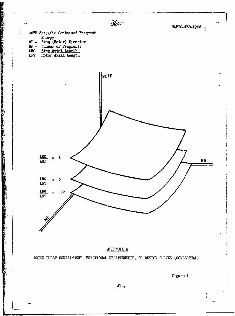
SUE Specific Contained FragmentEnergy
RD - Ring (Rotor) DiameterNF - Number of FragmentsLRG Ring Ax-il LengthLRT Rotor Axial Length
SCFE
I
LRG -LRT R, tD
LRG - 2LRT
LRG - 1/2LRT
APPENDIX A
ROTOR BURST CONTAINMENT, FUNCTIONAL RELATIONSHIP, OR DESIGN CURVES (CONCEPTUAL)
Figure 1
Al-4

11APTC...AED...i968
RING RADIALTHICKNESS-INCHES
NO.FRAGS t t t t
2
3
4
6
APPENDIX A
EXPERIMENTAL MATRICES FOR LARGE AND SMALL ROTOR BURST BURSTCONTAINMENT DESIGN CRITERIA DEVELOPMENT PROGRAM
Figure 2
A1-5

UAPTM-AED-1968
ACKIOWLEDGEMENTS
The author would like to credit and thank the following individuals fortheir excellent contributions to Phases VI and VII of the Rotor Burst Pro-tection Program.
- Patrick T. Chiarito, NASA Lewis Research Center, for overall directionand management of the Program.
- Doctors John W. Leech and Enmett A. Witmer, Massachusetts Instituteof Technology, for conceptual and analytical support and consultation.
37