natural roofing slate design and fixing guide roofing slate design and fixing guide ssq 44pg for...
TRANSCRIPT

CI/SfB (47) Ne5
May 1999
Natural roofing slate design and fixing guide
SSQ 44pg for PDFing 1/3/01 1:55 pm Page 1

Nail fixing method
4 Design considerations
4 Environmental conditions
4 Pitch of roof
5 Minimum laps
6 Batten sizes
6 Underlay
6 Ventilation requirements
6 Fixing methods
6 Types of nails
6–7 Coverage of slates
Application details8 Eaves
9 Verges
10–11 Ridges
12–13 Hips
14–15 Valleys
16–17 Abutments/parapets
18–19 Change of roof pitch/Mansards
20–21 Vertical cladding
22 Sitework
Hook fixing method
24 Design considerations
24 Environmental conditions
24 Pitch of roof
25 Minimum laps
26 Batten sizes
26 Underlay
26 Ventilation requirements
26 Fixing methods
26 Types of nails
26–27 Coverage of slates
Application details28 Eaves
29 Verges
30–31 Ridges
32–33 Hips
34–35 Valleys
36–37 Abutments/parapets
38–39 Change of roof pitch/Mansards
40–41 Vertical cladding
42 Sitework
This Guide has been prepared by the SSQ Group in
collaboration with practising UK architects, familiar
with both traditional (nail) and hook fixing practices.
It is intended to provide comprehensive information
on the design and fixing of SSQ natural slate roofing
and cladding products. Product literature on these
products, including Del Carmen, Caborco and Rocaber
slates, is available on request from SSQ.
For advise and assistance on the design, application,
installation and specification of SSQ slates, at any
time, please contact the SSQ Technical Services
Department on:
tel 0208 961 7725
fax 0208 965 7013
www.ssq.co.uk
email [email protected]
ReferencesPublications and organisations referred to in this guide:
BS 680: Part 2: 1971, Metric units
BS 747: 1994, Specification for roofing felts
BS 1202: Parts 2 and 3: 1974
BS 5250: 1989 (1995), Code of practice for control
of condensation in buildings
BS 5534: 1997, Code of practice for slating and
tiling, Part 1: Design
BS 6399: Part 2: 1997, Code of practice for wind loads
BS 8000: 1990 (1997), Workmanship on building
sites, Part 6: Code of practice for slating and tiling of
roofs and cladding.
BS 8104: 1992, Code of practice for assessing exposure
of walls to wind-driven rain
BRE Report, Thermal insulation: avoiding risks
BRE Digest 346: Parts 1 to 7
BS 747: 1977 (1986)
Building Regulations F2: 1995
BS 1202: Parts 2 and 3: 1974
Lead Development Association
34 Berkeley Square
London, WX1 6AJ
Telephone 0207 499 8422
Contents

Nail fixing

4 TELEPHONE 0208 961 7725
Design considerationsEffective design of a slate roof must take into account
a number of inter-related factors including site
exposure, the pitch of the roof, the type of slate
selected and the slate lap.
General guidance on the most important points to be
considered is given below. Full application and
sitework details are given on pages 8 to 22. Further
information can be obtained from BS 5534: 1997,
Code of practice for slating and tiling, Part 1: Design.
Reference should be made also to BS 8000: 1990
(1997), Workmanship on building sites, Part 6: Code
of practice for slating and tiling of roofs and claddings.
Environmental conditionsa Rain exposureThe degree of exposure of a building to driving rain
determines the minimum lap which should be specified.
The anticipated degree of exposure is given in Figure 1
(taken from BS 5534: Part 1: 1997).
Localised factors such as high buildings, buildings on
the slopes or tops of the hills and coastal sites, can
increase the exposure grading which should be applied
in a specific project. Table 1 on page 5 shows the
recommended minimum lap for moderate and severe
exposure sites.
For more detailed information on exposure to rain
refer to BS 8104: 1992.
b Wind upliftAdequate resistance to wind load and wind lift can be
provided by following the application details shown on
pages 8 to 21, taking into account minimum lap
recommendations given in Table 1.
Design calculations for wind load and wind uplift are
given in BS 5534: Part 1, BRE Digest 346: Parts 1 to
7 and BS 6399: Part 2: 1990, Code of practice for
wind loads, which replaces BS CP3: Chapter 5: Part
2: 1972.
Pitch of roofIn general, the lower the pitch of the roof, the greater
should be the lap. This longer lap will help to resist
both capillary action and wind uplift.
On steeper pitches with free-flowing drainage, smaller
slates may be used.
For exposed sites, wide slates with a greater lap
should be used (see Clause 18 of BS 5534).
LapThe lap is calculated by taking account of wind uplift,
exposure to driving rain and the roof pitch. Table 1
gives the recommended minimum laps for various roof
pitches and building exposures.
Figure 1 Categories of exposure
to driving rain
exposure
zones
Design work
approximate wind driven
rain (I/m2 per spell)
less than 56.5
equal to or greater
than 56.5

SSQ Design and fixing guide Nail fixing
TELEPHONE 0208 961 7725 5
Table 1 Minimum recommended laps in mm for different exposures and roof pitches
Moderate exposure – index between 3m2/s and 7m2/s
Slate size (mm) Roof pitchlength × width 85° 45° 40° 35° 30° 25° 221/2° 20°
600 × 300 65 65 75 75 90 105 125
500 × 300 65 65 75 75 90 90 115
500 × 250 50 65 65 75 75 90 105 120
450 × 300 50 65 65 75 75 90 100 120
450 × 250 50 65 65 75 75 95 110 125
450 × 230 50 65 65 75 75 100 115 130
400 × 300 50 65 65 75 75
400 × 250 50 65 65 75 75
400 × 200 50 65 65 75 75
350 × 300 50 65 65 75 75
350 × 250 50 65 65 75 75
350 × 200 50 65 65 75 75
Severe exposure – index greater than 7m2/s
Slate size (mm) Roof pitchlength × width 85° 45° 40° 35° 30° 25° 221/2° 20°
600 × 300 65 75 85 105 115 135 150
500 × 300 65 75 75 80 100
500 × 250 65 65 75 85 95 110
450 × 300 65 65 75 95 100 115
450 × 250 65 65 90 105 110 125
450 × 230 65 65 95 110 115 125
400 × 300 65 65 75 80 85
400 × 250 65 65 75 90 95
400 × 200 65 65 90 100 105
350 × 300 65 65 75 75 75
350 × 250 65 65 75 75 80
350 × 200 65 65 75 85 90

6 TELEPHONE 0208 961 7725
BattensRecommended timber batten sizes for natural slate
roofs are 50 × 25 mm, up to 600 mm rafter spans,
according to BS 5534: Part 1: 1997.
Battens should be set out horizontally across the roof
at a gauge calculated from the formula:
gauge =(length of slate – lap)
2Battens should be nailed at maximum 600 mm
centres, with the end of each length fully supported
and be not less than 50 mm wide by 25 mm thick.
Note If used, counterbattens should be a minimum
38 × 12 mm.
UnderlayUnderlay should be selected to meet the requirements
of Clause 13 of BS 5534: Part 1: 1997. Where the
underlay is not fully supported, it should be Type 1F
reinforced bitumen felt to BS 747: 1994 or other
approved material of adequate strength and durability.
VentilationTo comply with the Building Regulations F2: 1995
and BS 5250: 1989 (1995), Code of practice for
control of condensation in buildings, ventilation
equivalent to a 10 mm continuous vent must be
provided at the eaves on both sides of the roof when
the roof is of ‘cold roof’ construction and 25 mm if of
‘warm roof’ construction.
Additional ventilation at or near the ridge equivalent
to a 5 mm continuous vent is required in the case of
‘warm roofs’ and is also recommended if the case of
‘cold roofs’ if pitch of the roof is greater than 35°, or
if the span is greater than 10 metres.
‘Cold roofs’ are defined as being those where the
insulation is at ceiling level, and ‘warm roofs’ where
the insulation is in the plane of the roof (rafter level).
Fixing methodsAll SSQ natural slates can be fixed by using either
traditional holing and nailing (see pages 8 to 22) or
the hook fixing system (see pages 28 to 42).
NailsNails should be either aluminium alloy to BS 1202: Part
3: 1974 or copper to Part 2: 1974, or stainless steel.
They should be 20 to 25 mm longer than two
thicknesses of slate, but longer nails should be used at
the eaves course especially if a sprocket is used.
Coverage of slatesSee table 2 for coverage of all slate sizes at different
laps.
Total weight of slate roofThe total weight of slates on a roof can be calculated
as follows:
Example
Slate type Del Carmen
Slate size (mm × mm) 400 × 250
Weight of slates (kg/1000) 1235
Exposure Moderate
Roof pitch 40°
Roof area m2 150
Length of roof slope (m) 9.5
The headlap can be found from Table 1 by reference to
slate size, roof pitch, and exposure = 65 mm.
The slate coverage per m2 can be found from Table 2
= 23.9.
The total weight of slates on roof can be found from
the formula:
weight of slates (kg) × area of roof (m2) × slate coverage
1000
Therefore, the total weight=
1235/1000 × 150 × 23.9
= 4427 kg

SSQ Design and fixing guide Nail fixing
TELEPHONE 0208 961 7725 7
Table 2 Coverage of SSQ slates with nail fixing method
Slate size (mm) Lap (mm)length × width 50 65 75 80 90 100 110 115 120 130 140 150
Number of slates/m2
600 × 300 12.1 12.5 12.7 12.8 13.1 13.3 13.6 13.7 13.9 14.2 14.5 14.8
500 × 300 14.8 15.3 15.7 15.9 16.3 16.7 17.1 17.3 17.5 18.0 18.5 19.0
500 × 250 17.8 18.4 18.8 19.0 19.5 20.0 20.5 20.8 21.0 21.6 22.2
450 × 300 16.7 17.3 17.8 18.0 18.5 19.0 19.6 19.9 20.2 20.8 21.5
450 × 250 20.0 20.8 21.3 21.6 22.2 22.9 23.5 23.9 24.2 25.0 25.8
450 × 230 21.7 22.6 23.2 23.5 24.2 24.8 25.6 26.0 26.3 27.2 28.1
400 × 300 19.0 19.9 20.5 20.8 21.5 22.2 23.0 23.4 23.8
400 × 250 22.9 23.9 24.6 25.0 25.8 26.7 27.6 28.1 28.6
400 × 200 28.6 29.9 30.8 31.3 32.3 33.3 34.5 35.1 35.7
350 × 300 22.2 23.4 24.2 24.7 25.6 26.7 27.8
350 × 250 26.7 28.1 29.1 29.6 30.8 32.0 33.3
350 × 200 33.3 35.1 36.4 37.0 38.5 40.0 41.7
320 × 220 33.7 35.7 37.1 37.9 39.5 41.3 43.3
320 × 180 41.2 43.6 45.4 46.3 48.3 50.5 53.0
300 × 200 40.0 42.6 44.4 45.5 47.6 50.0
300 × 150 53.3 56.7 59.3 60.6 63.5 66.7
N.B No allowance has been made for wastage
Figure 2 Cold and warm
roof ventilation
Cold roof insulation at ceiling joist level Warm roof insulation at rafter level

8 TELEPHONE 0208 961 7725
EavesAt all eaves, a double course of slates is required,
comprising a course of short slates over which the first
course of full length slates is fixed.
The length of the eaves slates should be gauge + lap.
Fixing sequence at eaves1 Fix the underlay to extend over the tilting fillet and
fascia board into the gutter. The underlay should
overhang the fascia board by 50 mm.
2 Fix the first full course batten (the eaves batten)
so that the tails of the slates in the eaves and the
undereaves courses align, ensuring that they will
overhang 40 to 50 mm into the gutter. Fix the
undereaves batten immediately below the eaves
batten (see page 6 for minimum batten dimensions).
3 Lay the slates forming the undercourse on their
backs and head-nail them to the undereaves batten.
4 Fix the eaves course with the tails of the slates
aligning with the tails of slates in the undereaves
course.

SSQ Design and fixing guide Nail fixing
TELEPHONE 0208 961 7725 9
VergesWhere an undercloak is fixed it should consist of one
or more courses of slates not less than 4.5 mm thick,
laid riven side up and closely butted.
If more than one course is used, joints should be
staggered.
Verges should be finished with slate and slate-and-a-
half in alternate courses. Provision may be made for a
slight inward tilt from the verge.
Mortar for bedding and pointing; 1:3 cement/sand
pigmented to match colour of slates.
Fixing sequence at verge on brickwork1 Bed the undercloak in mortar so that it extends
40 to 50 mm from the face of the wall.
2 Fix verge slates flush with the undercloak.
3 Fill the gap between the undercloak and the slates
with mortar and strike off smoothly to provide a
flush joint.
Fixing sequence at verge on bargeboard1 Fix the undercloak with nails so that it overhangs
the face of the bargeboard by 40 to 50 mm.
2 Fill the gap between the undercloak and slates
with mortar and strike off smoothly to provide a
flush joint.
10 TELEPHONE 0208 961 7725
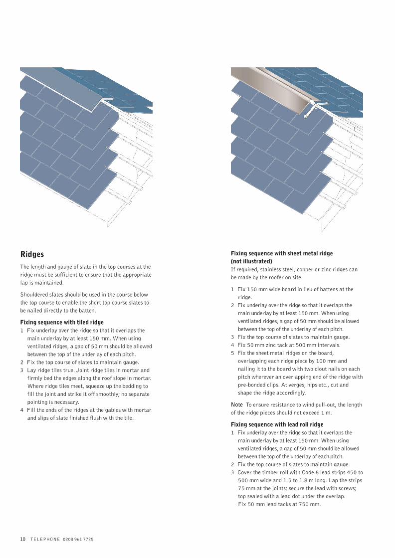
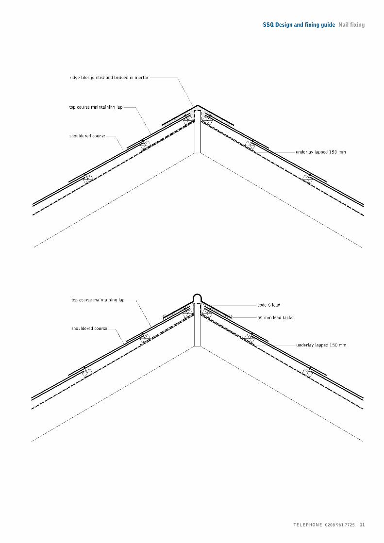
RidgesThe length and gauge of slate in the top courses at the
ridge must be sufficient to ensure that the appropriate
lap is maintained.
Shouldered slates should be used in the course below
the top course to enable the short top course slates to
be nailed directly to the batten.
Fixing sequence with tiled ridge1 Fix underlay over the ridge so that it overlaps the
main underlay by at least 150 mm. When using
ventilated ridges, a gap of 50 mm should be allowed
between the top of the underlay of each pitch.
2 Fix the top course of slates to maintain gauge.
3 Lay ridge tiles true. Joint ridge tiles in mortar and
firmly bed the edges along the roof slope in mortar.
Where ridge tiles meet, squeeze up the bedding to
fill the joint and strike it off smoothly; no separate
pointing is necessary.
4 Fill the ends of the ridges at the gables with mortar
and slips of slate finished flush with the tile.
Fixing sequence with sheet metal ridge (not illustrated)If required, stainless steel, copper or zinc ridges can
be made by the roofer on site.
1 Fix 150 mm wide board in lieu of battens at the
ridge.
2 Fix underlay over the ridge so that it overlaps the
main underlay by at least 150 mm. When using
ventilated ridges, a gap of 50 mm should be allowed
between the top of the underlay of each pitch.
3 Fix the top course of slates to maintain gauge.
4 Fix 50 mm zinc tack at 500 mm intervals.
5 Fix the sheet metal ridges on the board,
overlapping each ridge piece by 100 mm and
nailing it to the board with two clout nails on each
pitch wherever an overlapping end of the ridge with
pre-bonded clips. At verges, hips etc., cut and
shape the ridge accordingly.
Note To ensure resistance to wind pull-out, the length
of the ridge pieces should not exceed 1 m.
Fixing sequence with lead roll ridge1 Fix underlay over the ridge so that it overlaps the
main underlay by at least 150 mm. When using
ventilated ridges, a gap of 50 mm should be allowed
between the top of the underlay of each pitch.
2 Fix the top course of slates to maintain gauge.
3 Cover the timber roll with Code 6 lead strips 450 to
500 mm wide and 1.5 to 1.8 m long. Lap the strips
75 mm at the joints; secure the lead with screws;
top sealed with a lead dot under the overlap.
Fix 50 mm lead tacks at 750 mm.
SSQ Design and fixing guide Nail fixing
TELEPHONE 0208 961 7725 11

12 TELEPHONE 0208 961 7725
HipsIn cutting slates for hips, care must be taken to preserve
an adequate bond, using slate and a half slates.
Where pitches at hips are almost vertical, the hips can
be treated in the same way as verges.
Fixing sequence at mitred hip1 Fix 600 mm wide underlay, overlapping the main
underlay.
2 Cut slates carefully, ensuring that adequate width is
maintained at the head. SSQ do not recommend the
fixing of mitred hips on roofs where the angle of
the hip is 30° or less.
3 Hip slates must have an even size and shape at
every course.
4 Fix hip slates interleaved with lead soakers – nailed
to battens at the top edge – to provide a
weathertight close-mitred joint.
5 Cut slates of adequate width to connect with main
roof slates and hip slates. The slate nearest the hip
slate must remain a full slate.
Fixing sequence with lead roll hip1 Fix 600 mm wide underlay, overlapping the main
underlay.
2 Finish slating as close to timber roll as possible.
3 Cover the timber roll with Code 6 lead strips 450 to
500 mm wide and 1.5 to 1.8 m long. Lap the strips
75 mm at the joints equal to the lap of the slates.
Fix the 50 mm lead tack at 750 mm centres, under
the timber roll.
Fixing sequence with ridge tiled hipMortar 1:3 cement/sand pigmented to approved colour.
1 Fix 600 mm wide underlay, overlapping the main
underlay.
2 Fix hip to iron (to BS 5534: Part 1: Clause 12) to
hip rafter.
3 Cut slates to fit closely at junction.
4 Lay hip ridge tiles true and bed edges and joints
firmly in mortar, struck off smoothly to provide a
flush finish.
5 Cut first tile to align with corner of eaves.
6 Fill end of hip with mortar and slips of slate
finished flush.
Mitred hip
Lead roll hip
Ridge tiled hip

SSQ Design and fixing guide Nail fixing
TELEPHONE 0208 961 7725 13
Mitred hip
Lead roll hip
Ridge tiled hip

14 TELEPHONE 0208 961 7725
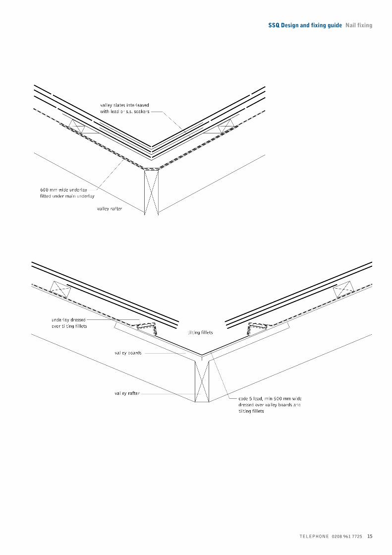
ValleysSpecial care should be taken to ensure that valleys
feature a clear unobstructed channel, at least 100 mm
wide. Increased kerbing may be required to
accommodate mass flow where the pitches on either
side of a valley are unequal.
For more information on open lead valleys, please
contact the Lead Development Association at:
34 Berkeley Square,
London WX1 6AJ.
Telephone 0207 499 8422
or contact the SSQ Technical Department.
Fixing sequence at mitred valley1 Lay a strip of underlay 600 mm wide over the
valley, underlapping the main underlay.
2 Cut slate-and-a-half carefully, ensuring that
adequate width is maintained at the tail.
3 Fix slates to interleave with Code 3 lead or
stainless steel soakers – nailed to battens at the top
edge – to provide a straight, weathertight, close-
mitred joint. The size of the soaker must be not less
than one slate in length; in width, it should be at
least a slate on both sides at the head and at least
half a slate on both sides at the tail.
Fixing sequence at valley gutter and open valley1 Fix valley boards down length of gutter.
2 Fix tilting fillets on either side of the valley board
and dress underlay over these tilting fillets.
3 Dress Code 5 lead strip at least 500 mm wide, into
the gutter and over the tilting fillets, extending at
least 40 mm beyond each tilting fillets.
4 Cut slates accurately, ensuring sufficient width is
retained at the tail, to overhang the tilting fillet but
leave a minimum of 100 mm clear width of valley.
Note The edges of the slating should not be tilted up
over open valleys.
SSQ Design and fixing guide Nail fixing
TELEPHONE 0208 961 7725 15

16 TELEPHONE 0208 961 7725
Abutments and parapets
a At top of roof slope1 Turn underlay 100 mm up abutments.
2 Fix short slates as the top course to maintain gauge.
3 Fix Code 6 lead tack, 50 mm wide, at 300 to 500 mm
centres and laps.
4 Fix Code 4 lead apron flashing in 1.5 to 2.0 m
lengths, wedge at the laps and at 450 mm centres
and secure into the brickwork joints to a depth of
at least 25 mm, dressed down 150 mm over the
slates.

SSQ Design and fixing guide Nail fixing
TELEPHONE 0208 961 7725 17
Abutments and parapetsb At end of roofs slopeAs nearly as possible, the abutment slates should be
slate and slate-and-a-half in alternate courses.
Soakers should be equal to slate length plus 15 mm.
The width should be equal to half the standard slate
width.
Note To avoid staining when lead is used, a smear
coat of patination oil should be applied to the surface
of the lead before fixing.
Fixing sequence1 Cut slates as required and interleave with Code 3
lead soakers, dressed to provide at least 75 mm
upstand to form a close, weathertight abutment, fix
soakers by turning down over the head of each slate.
2 Fix Code 4 lead flashing over soaker. Welt top
edge, secure into the brickwork joints, to a depth of
at least 25 mm, with lead wedges and point in
mortar.
18 TELEPHONE 0208 961 7725
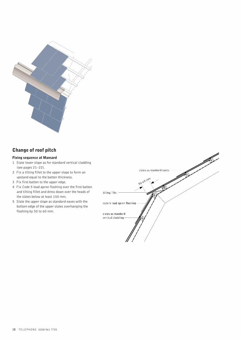
Change of roof pitchFixing sequence at Mansard1 Slate lower slope as for standard vertical cladding
(see pages 21–22).
2 Fix a tilting fillet to the upper slope to form an
upstand equal to the batten thickness.
3 Fix first batten to the upper edge.
4 Fix Code 5 lead apron flashing over the first batten
and tilting fillet and dress down over the heads of
the slates below at least 150 mm.
5 Slate the upper slope as standard eaves with the
bottom edge of the upper slates overhanging the
flashing by 50 to 60 mm.
SSQ Design and fixing guide Nail fixing
TELEPHONE 0208 961 7725 19
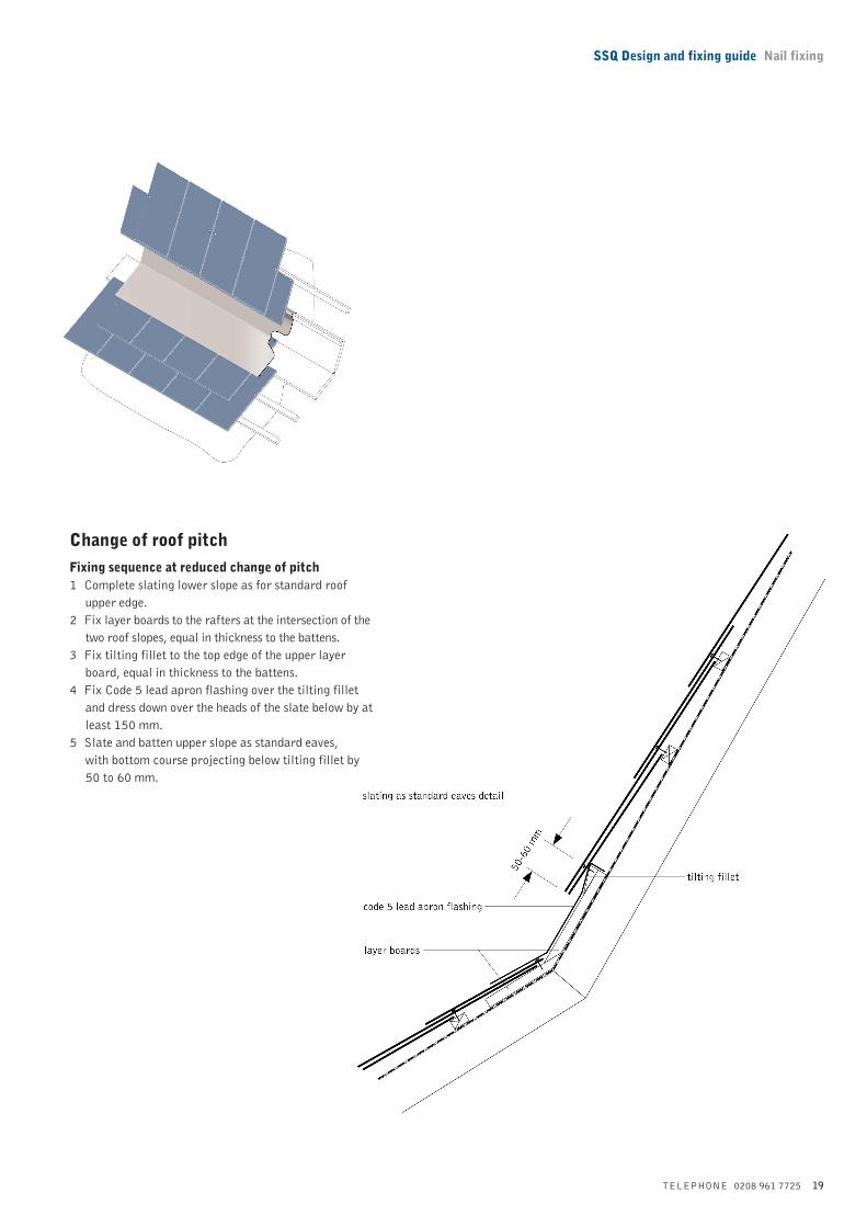
Change of roof pitchFixing sequence at reduced change of pitch1 Complete slating lower slope as for standard roof
upper edge.
2 Fix layer boards to the rafters at the intersection of the
two roof slopes, equal in thickness to the battens.
3 Fix tilting fillet to the top edge of the upper layer
board, equal in thickness to the battens.
4 Fix Code 5 lead apron flashing over the tilting fillet
and dress down over the heads of the slate below by at
least 150 mm.
5 Slate and batten upper slope as standard eaves,
with bottom course projecting below tilting fillet by
50 to 60 mm.
20 TELEPHONE 0208 961 7725
Vertical claddingSSQ slates used for external wall cladding provide a
highly aesthetic appearance as well being extremely
functional.
A wide range of cladding patterns can be achieved,
which can offer particular benefits of economy and
weather resistance as well as allowing versatility in
design.
Fixing sequence for vertical cladding
1 GeneralVertical slating or cladding may be fixed either
directly to batten or to battens and counter batten
soundly fixed on the wall face (see BS 5534: Part 1:
1997 Section 30). The minimum recommended head
lap is 50 mm.
If vertical slating or cladding is used as a facing for
timber framed construction, a suitable underlay is
required to act as a breather membrane.
2 At lower edgeFix slates at the lower edge of vertical work in the
same way as roof slating.
At external corners, or next to openings, full slate and
half width slate should be used on alternate courses
and soakers should be fixed at every course.
3 At top edgeCut slates for the top course to maintain gauge.
4 At abutmentsForm abutments with full slate and half slate on
alternate courses.
5 At anglesCut the slates as appropriate and interleave with lead
soakers fixed by nailing to battens at the top edge,
which is formed with full slate and half slate in
alternate course.
6 At abutments adjacent to openingsFix full slate and half slate on alternate courses,
interleaving with lead soakers. Fix flashings, suitable
for the particular window installations, around all
openings.
7 At gable endsSplay cut slates at the ends of courses to fit closely
under the verge, either by cutting wide slates to leave a
5 mm gap adjacent to the abutment or cutting the last
two slates at the end of every course so that the tail of
the end slate is almost at right angles to the verge.

SSQ Design and fixing guide Nail fixing
TELEPHONE 0208 961 7725 21
Half round
Fish scale
Bullnose

22 TELEPHONE 0208 961 7725
Storage on siteSlates should be stored in pallets whenever possible.
Slates should be stacked on their long edge on dry,
level ground. Two battens should be placed under row
of slates.
Preparatory work Sorting and stacking slatesEach slate should be inspected and the thicker end
selected for the tail. After being holed, they should be
stacked into three separate stacks.
Thick slates should be used on the lower roof (eaves),
medium slates on the middle roof and thin slates on
the upper roof (ridge) section.
Dressing and holing slatesSlates thick can be dressed and holed by hand using a
spike hammer. Thicker slates can be holed by hand or
machine.
When holing by hand, the slate must be laid flat over a
narrow iron and holed from the reverse side (bed)
towards the face, thus leaving a small countersunk
hole which allows for the head of the fixing nail.
Each slate should be holed twice at a distance from
the tail equal to the holing gauge (gauge + head lap
+ 8 to 15 mm) and between 20 and 25 mm from the
long edge of the slate.
When holing by machine, a boring method is
recommended. If a machine with a punching method
is used, care must be taken to ensure proper
maintenance and adjustment of the holing machine to
prevent excessive breakage. If slates are drilled, do
not drill more than one at a time.
Cutting slatesWhen using a slate cutting machine for cuts to hips
and valleys etc., proper adjustment and maintenance
is required.
To maintain adequate laps and allow proper fixing,
slates must not be cut too narrow. As a general rule no
slate should be less than one half the width of the slate.
At verges and abutments, the alternate courses must
be started with a slate-and-a-half or a slate if this is
not less than 145 mm.
At valleys, hips and other angled surfaces, the slates
must be cut on the rake using wider slates to maintain
an adequate width of head or tail of no less than 95 mm.
Traditional holing and nailing method When holing and nailing it is imperative that slates
are fixed in accordance with BS 5534, Code of
practice for slating and tiling.
Reference should also be made to BS 8000,
Workmanship on building sites: Part 6. SSQ will not
entertain claims for loss or damage where this has not
been strictly adhered to. The main stages are outlined
below:
1 Hole slates to the correct gauge, measuring from
the tail of the slates. The position of the holes can
be calculated using the formula:
holing gauge = gauge + lap + 8 to 15 mm
Holes should be between 20 and 25 mm from the
long edges of the slate. At the same time, sort the
slates into three or four groups of equal thickness.
See BS 8000: Part 6: Section 4. 3. 1.
2 Fix underlay as specified.
3 Mark out the roof to the correct batten gauge.
The gauge may be adjusted to provide equal
numbers of courses up the slope length, provided
that the specified lap is not reduced.
4 Fix battens.
5 Check width of slates and mark out the slate joints
(perpends) on battens. It is generally necessary to
mark out only every second perpend.
6 Load slates onto roof so that the thickest slates are
used in the lowest courses and the thinnest slates
near the ridge.
7 Fix slates to perpend lines, laying to give an all
overall appearance, with the tails of the slates
aligned.
Use slates of consistent thickness in any one course,
laid with the thicker end as the tail. Form verges by
using slate-and-a-half slates and full slates in
alternate courses to maintain bond. Fix each slate
with two nails through prepared holes.
Sitework