native instruments software synthesis reaktor
TRANSCRIPT

Reaktor -= Version 3 =- Operation Manual
Click here to show toolbars of the Web Online Help System: show toolbars
NATIVE INSTRUMENTS SOFTWARE SYNTHESIS
Reaktor
Version 3
Operation Manual
Terms of the license
The license you have purchased allows the use of the software by only one person at any one time. You may install this program on more than one of your computers provided that not more than one person uses it at the same time. In simple terms, this means you should treat this software like a book: You can lend it to a friend, but you cannot both read it at the same time.
Disclaimer of Warranties
We have made every effort to ensure that this product is as complete and error-free as possible. Software being complex as it is, we are advised to make the following disclaimer.
Limited Warranty
Native Instruments warrants that the software and hardware will perform substantially in accordance with the accompanying written materials for a period of 6 months from the date of receipt. Any implied warranties on the software are limited to 6 months.
Customer Remedies
http://www.reaktor.front.ru/source/reaktor3/00 operation manual.htm (1 of 3) [12/28/2002 10:00:16 PM]

Reaktor -= Version 3 =- Operation Manual
Native Instruments' entire liability and your exclusive remedy shall be, at Native Instruments' option, either (a) return of the price paid or (b) repair or replacement of the software or hardware that does not meet Native Instruments' Limited Warranty and which is returned to Native Instruments with a copy of your receipt. This Limited Warranty is void if failure of the software or hardware has resulted from accident, abuse, or misapplication. Any replacement will be warranted for the remainder of the original warranty period or 6 months, whichever is longer.
No Other Warranties
Native Instruments disclaims all other warranties, either express or implied, including but not limited to implied warranties of merchantability and fitness for a particular purpose, with respect to the software, the accompanying written materials, and any accompanying hardware.
No Liability for Consequential Damages
In no event shall Native Instruments or its suppliers be liable for any damages whatsoever (including, without limitation, damages for loss of business profits, business interruption, loss of business information, or other pecuniary loss) arising out of the use of or inability to use this product, even if Native Instruments has been advised of the possibility of such damages.
Caution! In case of careless operation by the user the REAKTOR software can produce audio signal levels which can be harmful to the ear and can damage loudspeakers and headphones when played back at high volume!
Please reduce the level at your mixer or amplifier before testing your designs! Always keep the gain of your monitoring equipment below the point where the software's maximum output level indicated by the bright red clip lamp in the Toolbar - can cause any damage.
This document is protected by copyright law and may not be copied, reproduced, translated or converted to electronic media without prior written permission.
Mention of the names of other manufacturers' products in this document is only for information purposes and does not constitute an infringement of trade marks.
Information in this document is subject to change without notice and does not represent a commitment on the part of NATIVE INSTRUMENTS.
©1997-2000 All rights reserved. Native Instruments Software Synthesis Gmbh
Dynamo, Reaktor, Generator and Transformator are
Trademarks of
NATIVE INSTRUMENTS Software Synthesis GmbH
http://www.reaktor.front.ru/source/reaktor3/00 operation manual.htm (2 of 3) [12/28/2002 10:00:16 PM]

Reaktor -= Version 3 =- Operation Manual
VST is a trademark of Steinberg Soft- und Hardware GmbH
All product- und company names are ™ or ® trademarks of their respective owners.
User's Guide written by:
Michael Kurz Stephan Schmitt Uwe Hoenig Reinhard Schmitz Gerhard Behles
Marius Wilhelmi
NATIVE INSTRUMENTS Software Synthesis GmbH
Schlesische Str. 28
10997 Berlin
Germany
Tel.:+49 30 61 103520
http://www.native-instruments.com
http://www.reaktor.front.ru/source/reaktor3/00 operation manual.htm (3 of 3) [12/28/2002 10:00:16 PM]

Contents
Click here to show toolbars of the Web Online Help System: show toolbars
● Copyrights● 1 Introduction ● 1.1 What is REAKTOR ? ● 1.2 Platform Specific Texts ● 1.3 Getting Started ● 1.4 The copy protection key ● 1.5 Support ● 1.6 Online Updates ● 2 Installation under Windows ● 2.1 System Requirements and Recommendations ● 2.2 Software Installation ● 2.3 Soundcard Settings ● 2.4 MIDI Interfaces ● 2.5 Uninstalling the Software ● 3 Installation under Mac OS ● 3.1 System Requirements and Recommendations ● 3.2 Software Installation ● 3.3 Audio Output Properties ● 3.4 MIDI Input ● 3.5 Additional MacOS Specifics ● 4 Open Sound Control (OSC) ● 5 First Steps in REAKTOR ● 5.1 Opening and Playing Example Ensembles ● 5.2 Your First DIY Synthesizer ● 5.3 Your First Self-Made Structure ● 6 The "Transformator" Tour ● 6.1 Practicing with Diletant ● 6.2 Percussion with Impaktor ● 6.3 Playing instruments with Simulant ● 6.4 FM and WaveSets with Stimulant and Vibrator ● 6.5 Playing Samples like WaveSets using Diktaphon ● 6.6 A tour through samples with Loopo, Plasma and Kompressor ● 6.7 4Dex ● 7 Interfaces ● 7.1 VST 2.0
http://www.reaktor.front.ru/source/reaktor3/index.htm (1 of 4) [12/28/2002 10:00:19 PM]

Contents
● 7.2 Windows Direct X Plug-in ● 7.3 ASIO ● 7.4 DirectConnect ● 7.5 MAS and FreeMIDI ● 7.6 MIDI File Player ● 8 Basic Operation ● 8.1 Mouse ● 8.2 Context Menus ● 8.3 Key Commands ● 8.4 Windows ● 9 Menus ● 9.1 File Menu ● 9.2 Edit Menu ● 9.3 Insert Menu ● 9.4 Settings Menu ● 9.5 System Menu ● 9.6 Preferences ● 9.7 Instrument ● 9.8 View ● 9.9 Help Menu ● 9.10 Context Menu ● 10 Toolbars ● 10.1 Ensemble Toolbar ● 10.2 Instrument Toolbar ● 11 Ensemble ● 11.1 Ensemble Structure ● 11.2 Ensemble Panel ● 12 Instruments ● 12.1 What is an Instrument? ● 12.2 Creating Instruments ● 12.3 Ports ● 12.4 Context Menu ● 12.5 Properties ● 13 Macros ● 13.1 What is a Macro? ● 13.2 Creating Macros ● 13.3 Ports ● 13.4 Context Menu ● 14 Structures ● 14.1 What is a Structure?
http://www.reaktor.front.ru/source/reaktor3/index.htm (2 of 4) [12/28/2002 10:00:19 PM]

Contents
● 14.2 Modules ● 14.3 Sources ● 14.4 Switches ● 14.5 Terminals ● 14.6 Wires ● 14.7 Event Signals ● 14.8 Context Menu ● 15 Panel Editing ● 15.1 What is a Panel? ● 15.2 What are Controls? ● 15.3 Panel Controls ● 15.4 Editing the Panels ● 16 Panel Operation ● 16.1 Mouse Control ● 16.2 Key Control ● 16.3 MIDI Control ● 16.4 MIDI Out ● 16.5 Snapshots ● 17 Sampling and Re-Synthesis ● 17.1 Sample Management ● 17.2 Sample-Maps ● 17.3 Sampler Properties Dialog ● 17.4 Akai Import ● 18 Table Modules ● 18.1 Properties ● 18.2 Context Menu ● 18.3 Advanced Operation ● 19 Appendix ● 19.1 Troubleshooting ● 19.2 Watching the CPU Load ● 19.3 Key Commands ● 19.4 4Control MIDI Unit ● 20 Glossary of Synthesizer Terms ● 21 Module Reference ● 21.1 Panel ● 21.2 MIDI ● 21.3 MIDI Out ● 21.4 Constant ● 21.5+,-,X,/ ● 21.6 Mixer
http://www.reaktor.front.ru/source/reaktor3/index.htm (3 of 4) [12/28/2002 10:00:19 PM]

Contents
● 21.7 Oscillators ● 21.8 Samplers ● 21.9 Sequencer ● 21.10 LFO, Envelope ● 21.11 Filter ● 21.12 Delay ● 21.13 Shaper ● 21.14 Audio Modifier ● 21.15 Event Processing ● 21.16 Auxiliary ● 21.17 Conversion Tables for Control Values
http://www.reaktor.front.ru/source/reaktor3/index.htm (4 of 4) [12/28/2002 10:00:19 PM]

1 Introduction
Click here to show toolbars of the Web Online Help System: show toolbars
1 Introduction
● 1.1 What is REAKTOR ? ● 1.2 Platform Specific Texts ● 1.3 Getting Started ● 1.4 The copy protection key ● 1.5 Support ● 1.6 Online Updates
http://www.reaktor.front.ru/source/reaktor3/01 introduction/01 introduction.htm [12/28/2002 10:00:21 PM]

1.1 What is REAKTOR ?
Click here to show toolbars of the Web Online Help System: show toolbars
1.1 What is REAKTOR ?
REAKTOR is a piece of software that turns your computer and soundcard into a powerful synthesizer and audio processing system. Its completely modular structure ensures that no limits are imposed on your imagination in the creation of electronic musical instruments and sound effects. From the simulation of relatively simple, analog synthesizers as well as large, complex modular systems, through sample players and FM synthesis up to exotic methods such as delay-line resonance or granular synthesis - REAKTOR will show itself to be capable of fulfilling all your desires.
REAKTOR'S ability to take on many different forms is the first major difference compared to hardware synthesizers and is its major advantage. "How do you want to sound today" would certainly be a good slogan for REAKTOR.
But even if the construction of synthesizers is not among your preferred activities, you have still made a good choice with REAKTOR. Together with the program you get a bunch of ready-made instruments that allow you to dedicate yourself without much ado to your favorite occupation:
making music.
Finally, you never know what will happen. Because of the way it is structured, REAKTOR always lets you take a look "behind the scenes" -another difference from hardware solutions where opening the cabinet rarely leads to an increased understanding of the internal workings (it just invalidates your warranty). It could be that you will find these insights so fascinating that after time you, who maybe always believed yourself to be "all thumbs", find yourself unexpectedly among the guild of synthesizer designers.
http://www.reaktor.front.ru/source/reaktor3/01 introduction/1.1 what is reaktor.htm [12/28/2002 10:00:23 PM]

1.2 Platform Specific Texts
Click here to show toolbars of the Web Online Help System: show toolbars
1.2 Platform Specific Texts
Depending on whether you are running the software on a Macintosh or on a Windows PC, different parts of the text may apply:
Text passages that are marked with the Windows icon only apply when using the software with Windows 95, Windows 98 or Windows NT.
Text passages that are marked with the MacOS icon only apply when using the software with MacOS.
http://www.reaktor.front.ru/source/reaktor3/01 introduction/1.2 platform specific texts.htm [12/28/2002 10:00:25 PM]

1.3 Getting Started
Click here to show toolbars of the Web Online Help System: show toolbars
1.3 Getting Started
One more word about this guide: We definitely recommend that after installation you first consult the chapter "First Steps", even if you are already an experienced synthesist. There you will learn much about how you can work quickly, efficiently and economically with REAKTOR, and your initial attempts at creating something will be that much easier.
http://www.reaktor.front.ru/source/reaktor3/01 introduction/1.3 getting started.htm [12/28/2002 10:00:27 PM]
1.4 The copy protection key
Click here to show toolbars of the Web Online Help System: show toolbars
1.4 The copy protection key
We at Native Instruments want to take the opportunity to thank you very much for buying a legal copy of Reaktor and consequently supporting future developments of this software.
In version 3 Reaktor uses a copy protection key (dongle) for the first time. This step was not an easy decision for Native Instruments but the persistend propagation of software piracy and a very realistic chance that this new copy protection scheme including a dongle can have a strong effect on the functionality of any Reaktor crack confirmed our resolution. Since the dongle replaces the enigma file in earlier Reaktor versions, it is used for encoding Reaktor files whenever an ensemble, instrument or macro is written. Be aware that using a cracked version without a dongle leads to incompatibility to files written by legal Reaktor versions.
Since all modem computers have a USB port we decided to supply Reaktor with a USB dongle. In the case that your computer does not support USB, we can offer you the exchange of your dongle to a Parallel, Serial, ADB or PCMCIA dongle. Check our website for the charges.
We strongly recommend to use Windows 98 Second Edition, ME or 2000 or MacOS 9 on the Mac since USB support might not work properly with earlier operating systems versions. For some earlier mainboards also a BIOS update might be neccesary for the operation of the USB port. Visit the homepage of the mainboard manufacturer to get a BIOS update.
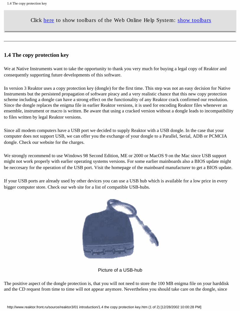
If your USB ports are already used by other devices you can use a USB hub which is available for a low price in every bigger computer store. Check our web site for a list of compatible USB-hubs.
Picture of a USB-hub
The positive aspect of the dongle protection is, that you will not need to store the 100 MB enigma file on your harddisk and the CD request from time to time will not appear anymore. Nevertheless you should take care on the dongle, since
http://www.reaktor.front.ru/source/reaktor3/01 introduction/1.4 the copy protection key.htm (1 of 2) [12/28/2002 10:00:28 PM]

1.4 The copy protection key
unfortunately we can not replace a lost dongle.
In the case of any difficulties with the installation of the dongle please contact the Native Instruments technical support.
We ask you for some understanding regarding this decision and hope you enjoy the third generation of Reaktor.
http://www.reaktor.front.ru/source/reaktor3/01 introduction/1.4 the copy protection key.htm (2 of 2) [12/28/2002 10:00:28 PM]

1.5 Support
Click here to show toolbars of the Web Online Help System: show toolbars
1.5 Support
NATIVE INSTRUMENTS is a young, independent company founded with a vision - to bring innovative, cutting edge software to musicians and empower them to make new sounds using the latest technology.
REAKTOR is already very powerful and well perfected in its current state. Nevertheless, NATIVE INSTRUMENTS is working steadily on improvements and extensions to the program and your suggestions and shared experiences are very important to us and always welcome.
If you have built sound synthesis structures or the like and would like to share them with other users, you can publish them on the Upload Page on our web site.
To take part in discussions with other users about everything connected with REAKTOR software, please join our e-mailing lists by using the subscribe form on our homepage. At this time we offer a mailing list for all users of NI products ([email protected]) and additionally a mailing list for Reaktor instrument designers ([email protected]).
And if you should ever have any problems with REAKTOR and need help, please contact our support line:
• Email: [email protected]
• Tel:+49 - 30 - 61 103520
• Fax:+49-30-61 103535
http://www.reaktor.front.ru/source/reaktor3/01 introduction/1.5 support.htm [12/28/2002 10:00:30 PM]

1.6 Online Updates
Click here to show toolbars of the Web Online Help System: show toolbars
1.6 Online Updates
Thank you for purchasing Native Instruments Reaktor 3! Be sure to regularly check our web page, www.native-instruments.com, for important updates and up-to-the-minute information. You can also find demo versions of all of our products, community bulletin boards, and more.
http://www.reaktor.front.ru/source/reaktor3/01 introduction/1.6 online updates.htm [12/28/2002 10:00:32 PM]

2 Installation under Windows
Click here to show toolbars of the Web Online Help System: show toolbars
2 Installation under Windows
● 2.1 System Requirements and Recommendations ● 2.2 Software Installation ● 2.3 Soundcard Settings ● 2.4 MIDI Interfaces ● 2.5 Uninstalling the Software
http://www.reaktor.front.ru/source/reaktor3/02 installation under windows/02 installation under windows.htm [12/28/2002 10:00:34 PM]

2.1 System Requirements and Recommendations
Click here to show toolbars of the Web Online Help System: show toolbars
2.1 System Requirements and Recommendations
To use REAKTOR you need a computer with at least the following specifications:
Hardware
• Intel Pentium class processor (233 MHz clock rate or higher) or AMD Athlon or Duron. Processors with lower floating point performance, e.g. the Cyrix 6x86 are explicitly not recommended. Note:
The maximum complexity of the sound synthesis structures and the number of voices that can be generated is proportional to the power of the CPU.
• 32 MByte RAM
• 50 MByte space on the hard disk, 300 MByte recommended for full installation.
• Soundcard compatible with Windows 95/98/ME/2000 or
Windows NT 4.0. To make use of audio input the soundcard must support 16-bit stereo full duplex operation or have an ASIO driver.
• MIDI interface for connection of a MIDI keyboard, MIDI controller or an external sequencer. It is possible to use the interface that is part of many common soundcards.
• A USB port for connecting the USB protection key.
Software
• Windows 95/98/ME/2000
http://www.reaktor.front.ru/source/reaktor3/02 install...ndows/2.1 system requirements and recommendations .htm [12/28/2002 10:00:36 PM]

2.2 Software Installation
Click here to show toolbars of the Web Online Help System: show toolbars
2.2 Software Installation
Installing the Copy Protection Key (Dongle)
Part of the protection of REAKTOR against illegal copying is dongle which is used when reading and writing files. Plug the dongle into the USB port after the REAKTOR installation.
If REAKTOR cannot find the dongle, please check if the USB port is properly installed on your computer. Therefore open the sytem panel, double click the sytem icon, click onto the Device manager tab, scroll down and look for the entry Universal Serial Bus Controller. If this entry doesn't appear in the device list or appears with an exclamation mark, reboot and press the Del key on you PC keyboard while booting to start the BIOS setup. Enable the USB port there if it is switched off.
Updating an Old Installation
A previous installation of REAKTOR can be removed by using the Add/ Remove Programs utility in the Control Panel. Select the entry "Native Instruments Reaktor 3" in the list and click on Add/Remove. The files which you have changed or added since the last installation will not be erased.
If you don't remove the last installation and choose the same installation folder, the old files will be overwritten by a new version. If you want to keep the last version working, please use a different installation folder for the new installation.
Installing the REAKTOR Software
Insert the installation CD into the CD drive. Now click on the Start button in the task bar, choose Settings and click on Control Panel. In the Control Panel window double-click on Add/Remove Programs and in the Properties dialog window that opens click on install..., then on Next. Now use the function Browse and on the CD in the folder \ REAKTOR choose the file called Setup.exe. Start the setup program by clicking on Finish.
Alternatively, you can use the Windows Explorer to open the CD and start the setup program by double-clicking on Setup.exe.
The setup program will guide you through the installation procedure. It creates the necessary folders and decompresses and copies the files required by the software.
The setup program will suggest C:\Program Files\Native Instruments\
http://www.reaktor.front.ru/source/reaktor3/02 installation under windows/2.2 software installation .htm (1 of 2) [12/28/2002 10:00:38 PM]

2.2 Software Installation
REAKTOR 3 as the path for the destination folder. Unless you choose another folder, this one will be created.
Installed Folders, Files and Shortcuts
The setup program creates the following subfolders in the installation folder:
• Bin\ contains the files needed for running the program
• Library\ contains the supplied library with separate folders for ensembles, instruments, and macros.
• Loopback\ has an installation of a MIDI Loopback Driver (freeware by Hubert Winkler). This is useful for interconnecting different MIDI programs running on the same PC (under Windows 95).
The entry REAKTOR for starting the program is generated in the Start menu under Programs Native instruments, unless you have chosen a different program group. There are also shortcuts to the ReadMe text and to two useful utilities: MidiMon and SysMon.
Unlocking the Installation
When you start the software for the first time, you are requested to enter your serial number. You can find it on the product package. We recommend that you copy it to this field:
Serial Number:
The installation CD must be inserted for unlocking the installation.
Serial Number and Registration
The serial number of your software license will be displayed in the window that opens on selecting About in the Help menu in the main window. You will need this serial number to register your software with us. To register yourself as a REAKTOR user please fill in the registration postcard or the online registration form on our website. Registered customers will be eligible to receive support and updates from us.
http://www.reaktor.front.ru/source/reaktor3/02 installation under windows/2.2 software installation .htm (2 of 2) [12/28/2002 10:00:38 PM]

2.3 Soundcard Settings
Click here to show toolbars of the Web Online Help System: show toolbars
2.3 Soundcard Settings
The REAKTOR software needs a soundcard for playing the sounds it produces. In addition, the soundcard's inputs can be used to process external audio signals live (REAKTOR as effects unit) or to sample them.
To use a standard soundcard as the audio interface for the software no extra drivers are needed. The REAKTOR software makes use of the standard WaveAudio or DirectX drivers installed with the cards.
However, some adjustment of the REAKTOR software's parameters is necessary to tune it to the hardware and achieve optimum performance. Choose Soundcard in the System Audio Port menu and open the appropriate settings dialog window by selecting System Audio Settings.... You can also open this dialog window by double-clicking on the Audio in or the Audio Out module.
http://www.reaktor.front.ru/source/reaktor3/02 installation under windows/2.3 soundcard settings.htm (1 of 4) [12/28/2002 10:00:41 PM]

2.3 Soundcard Settings
Audio Settings dialog window for stundurd soundcards
Devices
If more than one soundcard (or driver port) is installed, the selection boxes in Port and Out Port allow the choice of which soundcard (or which driver port) is to be used by the REAKTOR software. If the audio inputs of a soundcard are to be used, it must support 16-bit full duplex operation. Also, the In Port and Out Port that the software uses must be on the same card. Otherwise smooth operation cannot be guaranteed.
In the list of available ports for Out Port the available devices are marked MME: or DirectSound:. The latest DirectSound drivers for your soundcard are probably better optimized with regard to latency (delay) in the audio output than the earlier MME (WaveOut) drivers and normally perform better. We recommend that you try out all the available drivers, see what latency can be achieved with each and then use the one that performs best.
Do not use emulated DirectSound drivers (which are usually marked "emulated") because these are actually MME drivers made to look like DirectSound and will perform worse than all other options.
http://www.reaktor.front.ru/source/reaktor3/02 installation under windows/2.3 soundcard settings.htm (2 of 4) [12/28/2002 10:00:41 PM]

2.3 Soundcard Settings
A requirement for using DirectSound is that the Windows extension DirectX 5.0 (or later) is installed on your PC. Unfortunately, there are no DirectX drivers available yet for the In Port.
Note: The low latency technology employed in REAKTOR software makes high demands on soundcard drivers. Many drivers, especially older ones, are not able to cope and cause system crashes or incorrect operation particularly when using the audio input. Please make sure you have the very latest drivers available for your soundcard.
Latency
The delay that occurs during audio output (otherwise known as latency) depends on the size of the audio buffer that the software passes to the soundcard. For smooth operation this buffer must have a minimum length which depends mainly on the type of soundcard and driver used.
If you are installing REAKTOR software for the first time you can skip the settings described below and first get to know the system. Come back here later to optimize the latency so that you will get the best possible performance.
With the sliders Play Ahead of the Out Port section and Record Ahead of the In Port section you can adjust the size of the audio buffers. The smaller the buffers, the faster the response of REAKTOR. However, if the buffer is set too small, clicks will appear in the audio output.
Important: To get good performance from the REAKTOR software you must optimize the Play Ahead by hand every time you change your soundcard or update the soundcard driver.
You can optimize the buffer length for sound output on your system like this: Open an ensemble and play it while at the same time moving the slider for Play ahead in the Soundcard Properties dialog window. Move the slider to the left to reduce Play Ahead until you start to hear clicks in the sound output. Now move it back to the right a bit to find the point where the clicks disappear. Now you have found the minimum output buffer size for your card.
When using MME drivers, the sound will break up when Play Ahead is too small, with DirectSound drivers on the other hand, there will only be one glitch after which the effective latency suddenly becomes very large (about 1 second).
You can find the optimum position for the Record Ahead slider in a similar way. First draw a wire from the Audio-in module to the Audio-Out module in the ensemble structure window, connect an audio source (such as a CD player) to the soundcard input and listen to the soundcard output as usual. Now move the slider for Record Ahead to the left until clicking starts. Then slowly move it back to the right until the sound becomes clean. You have now found the optimum setting for the audio inputs of your soundcard.
http://www.reaktor.front.ru/source/reaktor3/02 installation under windows/2.3 soundcard settings.htm (3 of 4) [12/28/2002 10:00:41 PM]

2.3 Soundcard Settings
Connection for optimizing Record Ahead
When the soundcard is configured properly, the in and Out level meters in the Ensemble Toolbar appear in green/red, otherwise they appear gray.
By the way, the number of voices and the sample rate used inside the software don't have any affect on either latency or timing resolution, but they do, of course, affect overall performance due to the additional CPU load.
Please note that the input and output levels of the soundcard depend on the settings of the mixer on the card. You can control this device using the Windows accessory Volume Control, the Multimedia Properties of the Control Panel or a mixer program delivered with the soundcard.
http://www.reaktor.front.ru/source/reaktor3/02 installation under windows/2.3 soundcard settings.htm (4 of 4) [12/28/2002 10:00:41 PM]

2.4 MIDI Interfaces
Click here to show toolbars of the Web Online Help System: show toolbars
2.4 MIDI Interfaces
The MIDI Ports through which the REAKTOR software is to communicate with the rest of the world are selected in the MIDI Port dialog window, which is opened via the menu entry System MIDI Settings.... All the existing MIDI ports in your PC which are installed under Windows appear here and can be chosen for use with the REAKTOR. For details see section MIDI Settings...
If a MIDI input port has already been opened by another program, the software will not be able to use it and it will not appear under Available inports. In this case free up the port in the other program or make sure that REAKTOR starts up first. Conversely, an in-port has to be removed from the list of installed inports before another program has access to it.
http://www.reaktor.front.ru/source/reaktor3/02 installation under windows/2.4 midi interfaces.htm (1 of 3) [12/28/2002 10:00:44 PM]

2.4 MIDI Interfaces
MIDI Port dialog window
MIDI Input Channels
You can select MIDI channels for REAKTOR. The program receives MIDI only on channels you have activated here. MIDI data received on other channels will be ignored.
MIDI Input and Output Filters
http://www.reaktor.front.ru/source/reaktor3/02 installation under windows/2.4 midi interfaces.htm (2 of 3) [12/28/2002 10:00:44 PM]
2.4 MIDI Interfaces
You can set MIDI filters for the MIDI input and output seperately. If you wish that REAKTOR ignores specific MIDI controllers, select the appropriate checkboxes.
MIDI thru
Activate this checkbox if you wish REAKTOR to pass on incoming MIDI data directly to the MIDI output. MIDI thru can be used if you want to set your MIDI interface as MIDI input for REAKTOR but record the MIDI data in another program. If you control REAKTOR from a sequencer, you should not activate MIDI thru for REAKTOR, since in certain configurations you might get a MIDI loop.
Using REAKTOR with a Software Sequencer
You can control REAKTOR with another piece of MIDI software, such as a sequencer, running on the same computer. The REAKTOR CD contains a MIDI loopback driver called Hubis for use under Windows 95/98. This driver does not work with Windows NT and 2000, however, where you will need a special MIDI loop-back device designed for those operating systems (such as MIDI Yoke).
Hubis loopback driver provides four MIDI out- and in-ports named LB1-LB4 for use by other MIDI programs such as your sequencer. MIDI events routed to these ports are passed to the REAKTOR software inside the computer.
If you want to disable this internal connection to other MIDI programs, simply remove the entry (LB1 for instance) for the list of installed inports in the MIDI Port dialog window (System MIDI Settings...) by selecting it and pressing the Delete button.
If you want to connect REAKTOR'S MIDI output to the input of your sequencer you have to insert a port (LB2 for instance) into the list of installed out-ports.
http://www.reaktor.front.ru/source/reaktor3/02 installation under windows/2.4 midi interfaces.htm (3 of 3) [12/28/2002 10:00:44 PM]

2.5 Uninstalling the Software
Click here to show toolbars of the Web Online Help System: show toolbars
2.5 Uninstalling the Software
If you want to remove the software installation from your computer completely, we recommend the following procedure:
Open Start=>Settings=>Control Panel=>Add/Remove Programs On the page Install/Uninstall choose Native instruments Reaktor 3 from the list of installed programs. Click on Add/Remove and confirm deletion by clicking on Yes.
http://www.reaktor.front.ru/source/reaktor3/02 installation under windows/2.5 uninstalling the software.htm [12/28/2002 10:00:46 PM]

3 Installation under MacOS
Click here to show toolbars of the Web Online Help System: show toolbars
3 Installation under MacOS
● 3.1 System Requirements and Recommendations ● 3.2 Software Installation ● 3.3 Audio Output Properties ● 3.4 MIDI Input ● 3.5 Additional MacOS Specifics
http://www.reaktor.front.ru/source/reaktor3/03 installation under mac os/03 installation under mac os.htm [12/28/2002 10:00:48 PM]

3.1 System Requirements and Recommendations
Click here to show toolbars of the Web Online Help System: show toolbars
3.1 System Requirements and Recommendations
To use REAKTOR you need a computer with at least the following specifications:
Hardware
• Processor: PowerPC (250 MHz clock rate or higher). Note: The maximum complexity of the sound synthesis structures and the number of voices that can be generated is proportional to the power of the CPU.
• 32 MByte RAM
• OMS or FreeMIDl compatible MIDI interface for connecting a MIDI keyboard or an external sequencer.
• 50 MByte space on the hard disk, 300 MByte recommended for full installation.
• A USB port for connecting the USB protection key
Software
• MacOS8.6orhigher
• Opcode OMS or Motu FreeMIDl
http://www.reaktor.front.ru/source/reaktor3/03 install...mac os/3.1 system requirements and recommendations.htm [12/28/2002 10:00:51 PM]

3.2 Software Installation
Click here to show toolbars of the Web Online Help System: show toolbars
3.2 Software Installation
Installing the Copy Protection Key (Dongle)
Part of the protection of the REAKTOR software against illegal copying is a copy protection key for the USB port which is used when reading and writing files. Plug the dongle into the USB port after the REAKTOR installation.
Installing the REAKTOR Software
Insert the Installation CD into the CD drive and double-click on the CD icon.
The Installation CD will open. Start the setup program called REAKTOR Installer by double-clicking on it.
The installer first brings up a picture. When clicking on Continue a dialog opens up which allows you to select the setup type and the destination folder.
The setup program will suggest a path for the destination folder. Unless you choose another folder, REAKTOR will be created on the first hard disk.
Unlocking the Installation
When you start the software for the first time, you are requested to enter your serial number. You can find it on the product package. We recommend that you copy it to this field:
Serial Number:
The Installation CD must be inserted for unlocking the installation.
Serial Number and Registration
The serial number of your software license will be displayed in the window that opens on selecting About in the Help menu in the main window. You will need the serial number to register your software with us. To register yourself as a REAKTOR user please fill in the registration postcard or the online registration form on our website-Registered customers will be eligible to receive support and updates from us.
http://www.reaktor.front.ru/source/reaktor3/03 installation under mac os/3.2 software installation.htm [12/28/2002 10:00:53 PM]
3.3 Audio Output Properties
Click here to show toolbars of the Web Online Help System: show toolbars
3.3 Audio Output Properties
To access the settings for the Sound Manager open ^ Control Panel Sound and click on Sound.
Latency
The delay (latency) that appears between a MIDI event and the audio signal that it triggers should be short (under 20 ms) for proper performance.
Important: The OMS (Open MIDI System) introduces some amount of delay in the MIDI data stream when MacOS is using virtual memory. Therefore you must turn off virtual memory by going into 4 Control Panel Memory and setting Virtual Memory to Off.
http://www.reaktor.front.ru/source/reaktor3/03 installation under mac os/3.3 audio output properties.htm [12/28/2002 10:00:55 PM]

3.4 MIDI Input
Click here to show toolbars of the Web Online Help System: show toolbars
3.4 MIDI Input
REAKTOR uses OMS (Open MIDI System) or FreeMIDI to receive MIDI control signals from the rest of the world.
You can select the MIDI Port to be used in the OMS or FreeMIDI Settings dialog window, which is opened via the menu entry System MIDI Settings....
Using REAKTOR with a Software Sequencer
You can control the REAKTOR software with another piece of MIDI software such as a sequencer, running on the same computer. The connection can be made using the IAC (Inter Application Communication) driver which is part of OMS
http://www.reaktor.front.ru/source/reaktor3/03 installation under mac os/3.4 midi input.htm [12/28/2002 10:00:57 PM]

3.5 Additional MacOS Specifics
Click here to show toolbars of the Web Online Help System: show toolbars
3.5 Additional MacOS Specifics
The REAKTOR software is programmed to provide identical functionality on both Windows and Macintosh computer systems. However, hardware differences make complete compatibility impossible. When using the documentation for REAKTOR, please keep the following points in mind: Windows systems generally utilized a "back-slash" system to notate a directory structure. For example, a desired file may be found in the Macros: :First Steps directory. The Windows notation for this directory would be Macros\First Steps. The Windows notation standard is used throughout this manual.
Some of the system level dialog boxes may use different notation than listed in this manual. MacOS 8 (and greater) has a new file selection dialog, where the selection button's "Open" caption changes to "Choose" when a file is selected. If you do not see a button with the exact label listed in the manual text, you will generally be safe using the button whose label most closely matches the "intent" of the manual text.
http://www.reaktor.front.ru/source/reaktor3/03 installation under mac os/3.5 additional macos specifics.htm [12/28/2002 10:00:58 PM]

4 Open Sound Control (OSC)
Click here to show toolbars of the Web Online Help System: show toolbars
4 Open Sound Control (OSC)
OSC is an open, network-independent protocol developed for communication among computers, sound synthesizers, and other multimedia devices. Compared to MIDI, OSC provides increased reliability, greater user convenience, and more reactive musical control. Open Sound Control is useful in any situation where multiple music applications have to work together on the same computer or on networked computers. While MIDI only has the parameters defined in the standard (note on/off, pitch bend, control change, etc.), OSC lets each program have its own symbolic, hierarchical, and dynamic address space.
OSC can be used with any networking technology, including TCP/IP based LANs and the internet. OSC's time tags and bundles of messages provide for exact timing of musical results even if the network has latency and jitter. OSC supports a variety of argument types which will be successively integrated into future releases of REAKTOR.
Application areas The OSC implementation of REAKTOR allows an easy setup of
• Internet-based collaborative international music making
• Sound installations with dozens of computers in a single room coordinating with each other
• Coordinating synthesis between two (or more) computers to increase the total processing power
• Communication between music software applications within a single computer.
The OSC implementation in the current Reaktor version only serves for transmitting MIDI data between two or more Reaktor computers. The OSC control data will be transmitted in parallel to MIDI. Additionaly to the general Reaktor requirements you will need an ethernet card to use OSC. Also the TCP/IP and UDP protocol stacks must be installed on your computer.
If you want to use OSC in Reaktor you have to activate it first by clicking the menu entry OSC/Enable OSC. Now you have access to the OSC Settings... dialog.
For sending data to another computer you have to know its IP address and enter it using the Add button in the OSC dialog. You also have to define a port number for the IP address which has to be the same as entered in the Local configuration Port field of the client. OSC data received on other ports will be ignored by REAKTOR.
It is possible to enter the IP adresses of more than one computer so that REAKTOR is able to send OSC data to several other Reaktor applications.
http://www.reaktor.front.ru/source/reaktor3/04 open sound control (osc)/04 open sound control (osc).htm (1 of 3) [12/28/2002 10:01:00 PM]
4 Open Sound Control (OSC)
You can define a Scheduler time offset in milliseconds for improving timing stability. In this case the OSC data is buffered on the client computer to decrease jittering.
Use the following instructions related to your operating system for finding out the ip address of your network configuration:
Windows 95/98/ME
• Click on the Start button
• Select Run...
• In the dialog box type winipcfg and press OK. If a message dialog box appears stating that winipcfg could not be found, you probably need to install the TCP/IP networking component which contains the winipcfg program.
• Record the number that appears in the IP Address field. This is 9 decimal digits (digits 0-9) in four pairs of digits separated by dots (e.g., 123.456.7.89).
Windows 2000
• Click on the Start button
• Select the Run folder.
• Enter cmd.exe.
• At the command prompt type ipconfig /all and press Enter.
• Record the number that appears in the IP Address field. This is 9 decimal digits (digits 0-9) in four pairs of digits separated by dots (e.g., 123.456.7.89).
Windows NT
• Click on the Start button.
• Select the Programs folder.
• Select the Command Prompt.
• At the command prompt type ipconfig /all and press Enter. If a message appears stating that 'ipconfig' could not be found, TCP/IP networking needs to be installed.
http://www.reaktor.front.ru/source/reaktor3/04 open sound control (osc)/04 open sound control (osc).htm (2 of 3) [12/28/2002 10:01:00 PM]

4 Open Sound Control (OSC)
• Record the number that appears in the IP Address field. This is 9 decimal digits (digits 0-9) in four pairs of digits separated by dots (e.g., 123.456.7.89).
MacOS
• From the Apple menu select Control Panels.
• Select TCP/IP. The TCP/IP control panel should now open.
• Record the number that appears in the IP Address field. This is 9 decimal digits (digits 0-9) in four pairs of digits separated by dots (e.g., 123.456.7.89).
http://www.reaktor.front.ru/source/reaktor3/04 open sound control (osc)/04 open sound control (osc).htm (3 of 3) [12/28/2002 10:01:00 PM]

5 First Steps in REAKTOR
Click here to show toolbars of the Web Online Help System: show toolbars
5 First Steps in REAKTOR
The purpose of this chapter is to make you familiar with the basics of the operation and the functionality of REAKTOR and how to program it.
By the way, we will dispense with trying to tell you that REAKTOR is a very simple affair and that within only a few minutes you will have programmed your own physical modeling synthesizer. That would be a lie. The fact is that REAKTOR is a complex program that offers complex functions which allow you to achieve complex things. And if that's just what you want to do, you won't really get around an intensive initial learning phase. After all, real success never comes easy.
But don't worry. You can work with REAKTOR at a complex level, although you don't have to. As you will see in our first tour, it is possible to make music with the software using a number of different instruments, even without any knowledge of synthesis methods or processing structures. You simply help yourself to the provided library.
● 5.1 Opening and Playing Example Ensembles ● 5.2 Your First DIY Synthesizer ● 5.3 Your First Self-Made Structure
http://www.reaktor.front.ru/source/reaktor3/05 first steps in reaktor/05 first steps in reaktor.htm [12/28/2002 10:01:02 PM]

5.1 Opening and Playing Example Ensembles
Click here to show toolbars of the Web Online Help System: show toolbars
5.1 Opening and Playing Example Ensembles
First make sure that your MIDI controller instrument (master keyboard or MIDI workstation) is connected to one of the MIDI inputs of your computer. The input port should have been activated under installed Ports. (For more information about activating MIDI-Ports, see section MIDI Settings... on page 97). The MIDI transmit channel on your controller should be set to 1.
Alternatively, you can just use the QWERTY keys on your computer keyboard to trigger notes (see section Musical Note Keys on page 182 for the key mapping).
Panel Window for Synth1
Synth1
Now open the folder Ensembles\First Steps using the selection File Open... in the menu bar at the top of the REAKTOR software's main window. Select Synth1.ens and click on Open.
You should first take a quick look at the upper Toolbar. Is the green Out level meter active (not gray)? If it is, you can now play Synthl. If not then click the orange main power button to first turn on your new synth. Now you can let it rip! By the way, if the number display next to the main power button shows Over or a warning message pops up ("Processor Overload!") to inform you that audio processing has been turned off, then you will need to reduce the number of voices in the second Toolbar from 6 to a smaller number or choose a lower sample rate than the initial 44100 Hz. And if the Out level meter
http://www.reaktor.front.ru/source/reaktor3/05 firs...aktor/5.1 opening and playing example ensembles.htm (1 of 5) [12/28/2002 10:01:04 PM]

5.1 Opening and Playing Example Ensembles
should ever light up red, this indicates that the soundcard is being overloaded - in which case you need to reduce the volume inside the REAKTOR software.
With every note you play, the two LEDs in the Toolbars labeled MIDI should light up blue. The upper one indicates that the system is receiving MIDI data, and the lower informs you that the MIDI data is being correctly passed to the instrument.
Synthl is a replica of a simple 6 voice analog synthesizer. It contains one sawtooth oscillator, a 24-dB lowpass filter, an LFO that affects the pitch and one ADSR envelope for both filter and amplitude.
In the window labeled Synthl - Panel you can find the control elements that are available for changing the sound. From left to right, these are: A(ttack), D(ecay), S(ustain) and R(elease) for changing the shape of the envelope. Cutoff for controlling the filter cutoff (or comer) frequency, Reson(ance) for the amount of boost applied to the frequencies near this cutoff frequency, Env for setting how much the filter is affected (modulated) by the envelope, and finally Depth for setting the LFO intensity and Rate for the LFO speed.
If you have ever before had your hands on a synthesizer then dealing with this straightforward device should not be much of a challenge. On the other hand, if Synthl is your first synth, you now have the opportunity to experiment with the effect that these few but essential synthesis parameters have on the sound. And there's no reason to worry about getting too lost.
If during your experiments you should come across a sound that you particularly like, you can save it. For this you move your mouse pointer to the second Toolbar, the instrument Toolbar where there is a row of buttons from which we now choose the camera icon. This one assists in creating so-called Snapshots, which correspond to the "patches" or "programs" in other programmable synthesizers. A window opens in which you give the sound a number (No) and a name (Label), then save it by clicking on the Store button. If you now open the Snapshot selection box to the left of the camera icon, your creation will appear there along with the example sounds programmed by us.
Padecho
The next candidate we are going to have a closer look at is called Padecho.ens. You will find it in the same folder from where we previously pulled out Synthl. So: open File Open..., move to the folder Ensembles\ First Steps, select Padecho.ens and load it by clicking on Open.
Now you will just be asked whether you want to save the changes you have made in Synth 1. You probably want to answer No here, unless you have just found a new sound that's worth keeping.
At first you can now see only one window the Ensemble window The ensemble is the highest level in REAKTOR and is, in a manner of speaking, a bird's eye view of the complete working environment that is available to you In this case it contains Pad, which is a synthesizer, and the stereo delay effect Echo Stereo The output of the synthesizer is connected to the two inputs of the effects unit whose outputs are connected to the two inputs of the Audio-Out module
You will find this Audio-Out module in every ensemble It represents the software's connection to the rest of the world, which is normally the audio output of your soundcard, but can also be the DirectX Plug-In connection to another piece of software Its counterpart is the Audio-ln module which represents the audio inputs of your soundcard (or the DirectX Plugin connection) and which is also present in every ensemble In this case it is muted, as you can see by the red cross which is displayed over the status LED in the Audio-in module, because the Padecho ensemble doesn't need any audio input
http://www.reaktor.front.ru/source/reaktor3/05 firs...aktor/5.1 opening and playing example ensembles.htm (2 of 5) [12/28/2002 10:01:04 PM]
5.1 Opening and Playing Example Ensembles
A quick look at the Padecho ensemble already brings to light two essential features of REAKTOR One is that an ensemble can consist of more than one instrument The other that its generative power is not restricted to synthesizers, because Echo Stereo is obviously an effects unit
Naturally, you can play at the ensemble level, as pressing a key on your MIDI instrument will show, but there are no control elements at your disposal which does detract from the entertainment value quite a bit
So let's make the available controllers visible The first step is clicking the right mouse button (Windows) or Ctrl key + mouse button (•!- MacOS) mouse button on the empty grey area of the ensemble window A so-called context menu appears, in which you choose the entry Panel The Ensemble-Panel window which appears already gives access to two knobs, that is Main for controlling the master volume of the ensemble and Tune for setting the master tuning
Next click the right mouse button (Windows) or Ctrl key + mouse button (•i- MacOS)on the Pad module Another context menu opens and again choose Panel The panel window for the synthesizer with its controllers opens up Finally, a click with the right mouse button (Windows) or Ctrl key + mouse button (<- MacOS)on the Echo Stereo module and selection of Panel opens the panel of the effects unit, so that you now have visible all the controllers provided in this ensemble
Before we allow you a few moments of musical activity with the Padecho ensemble, let's make a few short comments regrading its structure The pad synth contains two oscillators that both generate a pulse-wave The tuning of the second oscillator can be controlled relative to the first one coarse with the knob labeled interval and fine with the Fine knob The pulse width of both oscillators is set with PWidth and can also be modulated with the LFO LFO rate sets the speed and Depth the amount of modulation The controllers for the ADSR envelope, which again affects both filter and amplitude, as well as the knobs to the right for controlling the filter, correspond to those we got to know in Synth 1
The Echo Stereo consist of two delay lines, one of which processes the left and the other the right stereo channel Their delay times can be controlled independently of each other using Del L and Del R, where a setting of zero means that there is no delay The desired number of echo repeats is set with the knobs F(eed)Back and Cross, where FBack controls the amount of signal of a channel (L or R) going back into itself and Cross the amount going into the respective other channel Finally, Wet-Lvlsets how much of the original signal goes through the delays, and thus it controls the strength of the effect
FM Overdrive
The next example we want to present to you is called Fm2opsov ens You can also find this in the by now familiar First Steps folder and opening it should be present no difficulty to you as an already somewhat advanced REAKTOR user
As a quick look at the Ensemble window shows, we again have a combination of two devices here the synthesizer FM 2 ops followed by the distortion effect Overdrive
The FM Overdrive synthesizer is an example of the flexibility of REAKTOR In addition to subtractive systhesis, REAKTOR is capable of other types of synthesis In this case, FM (frequency modulation), made popular by the Yamaha DX series of synthesizers, is used for tone generation
In our example there are not 6 operators as in the DX7, or 4 like in the smaller DX models, but only 2 operators, so the whole structure remains quite clear Both operators consist of an oscillator that generates a sine wave One is the so-called earner, responsible for generating the fundamental wave and thus setting the pitch of the sound The other operator is the modulator that affects the frequency of the carrier and controls the timbre
http://www.reaktor.front.ru/source/reaktor3/05 firs...aktor/5.1 opening and playing example ensembles.htm (3 of 5) [12/28/2002 10:01:04 PM]

5.1 Opening and Playing Example Ensembles
Play a few notes on your MIDI instrument Not very exciting, right9 Now slowly push the FM fader upwards and listen how the sound changes A bell-like element starts to creep into the sound until it dominates it completely when the maximum position is reached On a technical level, all we have done by sliding the FM knob up is to increase the level of the modulator and thereby determine how much it modulates the carrier's frequency
In the next step we turn our attention to the Interval knob The effect that this parameter has should quickly become quite clear The knob placed next to it. Detune, allows you to make fine adjustments to the interval setting
A very simple envelope is responsible for determining the sound's development over time The carrier's envelope, which controls volume, has only the two parameters D(ecay) and R(elease) The envelope for the modulator is even simpler and has only the one knob for setting the decay, labeled Mod-D
Armed with this knowledge you should not find it difficult to create your own sounds with this 2 operator FM synthesizer, and to do it with a sense of purpose
Let's turn briefly to the Overdrive, the purpose of which is simply to furnish your FM sound creation with some amount of acoustic grit The best thing is probably if you first try out the various snapshots before dedicating yourself to the following explanation of this device
Drive sets the level of the signal that is sent to the distorting element and therefore controls the amount of dirt that is generated With Asym it is possible to modify the overtone spectrum of the signal in such a way as to make it "warmer", i e , to make it sound as if the sound was generated using a valve (tube) circuit The distortion circuit is followed by a filter with the parameters Freq(ency) for setting its cutoff frequency and Emph(asis) to emphasize this frequency The setting of the Volume knob determines the output level of the sound signal
16-Step Sequencer plus Bassline
The ensemble Squncl6ens, with which we are now going to experiment, can also be found in the folder First Steps
A look at the Ensemble window tells us something about the construction of this setup Sequence16, a 16-Step sequencer (another function that REAKTOR can provide) controls Bassline-Puls, a kind of 303 clone, whose signal reaches the audio output via the Panner
The Panel window of the 16-Step sequencer is already open and the Run button seems to be smiling at us in such an inviting way, so we will just give it a push and promptly the sequence of 16th notes starts bubbling away You can change the pitch for every step with the Pitch faders in the top row, and the volume for each step with the Lvl (Level) faders in the row below The tempo is adjustable using the BPM knob (next to the Run button) and the length of the notes can be manipulated with knob labeled Length
Finally, the Reset button located underneath Run resets the sequence to step 1 every time it is pressed If it is pressed while the sequencer is running, a nice shifted pattern can be generated If it is pressed while the sequencer is stopped, this ensures that, on starting, the sequence will begin at the first step and not somewhere in the middle
A click with the right mouse button (Windows) or Ctrl key + mouse button (^ MacOS) on the instrument Bassline-Puls in the ensemble window and selection of Panel in the context menu give you access to the control elements of the synthesizer This layout corresponds to what you may know from a 303, but even if you have never seen such a beast, with such a small
http://www.reaktor.front.ru/source/reaktor3/05 firs...aktor/5.1 opening and playing example ensembles.htm (4 of 5) [12/28/2002 10:01:04 PM]

5.1 Opening and Playing Example Ensembles
number of controls it's unlikely that any confusion will arise Just turn any knobs you want and listen to the result
As you have probably already noticed, the sound in this ensemble is always moving back and forth between the left and right speakers. The Panner is responsible for this. Now open the panel (you know, context menu etc.). Very simple, isn't it? With Amount you set by how much the signal travels between the left and right channel and Rate is the speed of this movement. That is all there is to it.
Sample Loop Player
The final example for illustrating REAKTOR'S capabilities is called Wav-play.ens. You find it, with the other REAKTOR examples, in the folder First Steps.
This ensemble is made up of the units Loop-Player and 12-Band. Before you can hear anything here, you first need to load a sample into the Loop-Player. Click the right mouse button (Windows) or Ctrl key + mouse button (t MacOS) on Loop Player in the panel window and choose WAV import....in the context menu that appears. In the file selection dialog window select any of the WAV files that you may have on your hard drive (e.g. in C:\Windows\Media) and load it by clicking on Open. Presto, a click on the Run button and you hear the newly loaded sample as a loop.
You can use any sample you happen to have available in WAV format (PCM). If the file being loaded is recorded at a different sample rate than that currently used by REAKTOR (here 44.1 kHz) or if it is in stereo, a message will pop up for your information.
The whole point of the Wav-play ensemble, however, is to be found in the 12-Band effect whose panel you should open now. The panel that appears looks very much like the classic control panel of a graphic equalizer - that is, faders which allow the level of various frequency bands to be controlled. What we have here is a filterbank which allows even more dramatic manipulation of the sound than an equalizer. The number above each fader tells you at how many cycles per second (Hertz, often abbreviated Hz) the band which the fader controls is located. Try out the effect of the different frequency bands on the sound, while the loop is running. You will notice that it's not just the timbre that changes, but that it is possible to nearly remove entire parts and so manipulate the musical character of the loop.
http://www.reaktor.front.ru/source/reaktor3/05 firs...aktor/5.1 opening and playing example ensembles.htm (5 of 5) [12/28/2002 10:01:04 PM]

5.2 Your First DIY Synthesizer
Click here to show toolbars of the Web Online Help System: show toolbars
5.2 Your First DIY Synthesizer
As you may have noticed in the previous examples and by further rummaging through the ensemble library, REAKTOR offers a wealth of ready-made instruments, effects units and combinations. But the true thrill of REAKTOR is in the possibility of designing and constructing your own instruments. And as you will see, it isn't difficult if approached in the right way.
How about an analog synthesizer in the good old fashion? Let's do it using subtractive synthesis, where an oscillator first produces a signal rich in high frequency components, some of which are subsequently removed using a time variable filter. All right, here we go.
Preparation
To construct our synthesizer we will use a method that is very effective -the use of so-called Macros.
In REAKTOR terminology, macros are functional blocks with which the construction of complex structures becomes quite easy, and most importantly, everything remains clearly laid out. In REAKTOR you already have an extensive library of such macros at your disposal, and we will help ourselves to it.
Initially, turn off the main switch in the Toolbar, so that you don't get startled when the half-finished construction suddenly starts making noises.
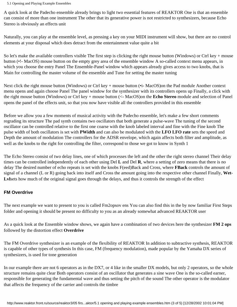
To begin with we will prepare the workspace in which to construct the synth. Please open the File menu at the top of the Ensemble window and choose the entry New. If you have made some changes in the current ensemble, you will first be asked whether you want to save these changes. After this you will see (in the Ensemble window) our old friends Audio-Out and Audio-In.
First we need a shell - a box so to speak - in which we will construct our synth. For this we take an empty instrument module which we find in the library. Click with the right mouse button (Windows) or ctrl key + mouse button (t MacOS)in the Structure window and in the context menu choose lnstruments=>New=>Out1. The empty instrument we need appears in the structure.
Now, in the Ensemble window, click on the Out port of the Instrument, move the pointer to the L input of the Audio-Out module and once more click the mouse button. Do you now see a connection between the two components? If not, try again. If so, we congratulate you on creating your first virtual Wire. In the same way connect the Out port of the Instrument to the R input of Audio-Out so that you can later hear the sound on both channels.
http://www.reaktor.front.ru/source/reaktor3/05 first steps in reaktor/5.2 your first diy synthesizer.htm (1 of 5) [12/28/2002 10:01:07 PM]
5.2 Your First DIY Synthesizer
An empty instrument connected to Audio Out
Choice of Components
For our synth we need one or more oscillators whose signal should go through a filter. The volume of the oscillators should be controlled additionally by an envelope, and that's it. We will now assemble these components.
Click with the right mouse button (Windows) or Ctrl key + mouse button ( MacOS)on the instrument module and then select Panel to open the panel window. The panel obviously doesn't contain any controllers yet because we haven't built anything so far. In the same way open the Structure window contains an output terminal (Out) and a Voice Combiner (}). In the remaining space we load the components we have just talked about.
Click with the right mouse button (Windows) or ctrl key + mouse button ( MacOS)in the Structure window and in the context menu choose Macros=>0scillator=>0sc (pulse, saw, tri). In the Structure window you can now see the macro. A quick look in the Instrument-Panel window, which was empty until just a few moments ago, shows the first few controllers. We're making progress.
Before we go on we should make sure that the oscillator is working. As a precautionary measure, first open the Ensemble-Panel window (click with the right mouse button (Windows) or Ctrl key + mouse button ( MacOS)in the empty ensemble window etc.) and set the Level fader to, let's say, -10 to avoid any nasty surprises during the following audio test.
In the Instrument-Structure window, connect a wire from the Out port of the Osc 3 Wave macro to the input of the Voice Combiner module (marked with the symbol: }) by clicking first on one port to start the wire and then on the other port to finish connecting it. Let's add an ADSR volume envelope to the Oscillator-Macro by using the context menu again. Connect the lower Out Output of the ADSR macro to the A input of the Osc 3 Wave macro. Now we only need two more important MIDI modules to get a connection to an external MIDI input device. Insert the module NotePitch (Modules=>MIDI=>Note Pitch) and connect it with the P input of the Oscillator macro. Finally we need a Gate module (Modules=>MIDI=>Gate), which has to be connected with the G input of the ADSR macro. Press the power button in the Toolbar and you should hear a sound when you press some keys on your MIDI device. This is it, our oscillator in its raw form - not really beautiful but audibly functional.
Before loading the next component, the filter, first remove the wire you have just made between the Oscillator and the Voice
http://www.reaktor.front.ru/source/reaktor3/05 first steps in reaktor/5.2 your first diy synthesizer.htm (2 of 5) [12/28/2002 10:01:07 PM]

5.2 Your First DIY Synthesizer
Combiner. Simply click on the two ports again, as if connecting a second wire, and the connection is gone. Alternatively, just click on the wire (it changes color) and press the Del key (Delete on the Macintosh) - same result.
Now load a Filter macro in the same manner as previously the oscillator. You find it in the context menu under Macros=> Filter without FM=>4-P Filter (BP, BLP, LP).
On considering these components you may may question if a synth with only one oscillator is the be all and end all. After all, it's well known that two oscillators simply give a fatter sound. OK, so let's add another one:
click the right mouse button (Windows) or Ctrl key + mouse button
( MacOS)on the Osc 3 Wave macro (careful, don't hit one of the ports), select Copy from the context menu, click the right mouse button (Windows) or Ctrl key + mouse button ( MacOS)on some patch of empty space in the Structure window, select Paste, done.
It is important to maintain a clean design - especially when dealing with a complex synthesizer. It's easy to create a chaotic layout, then spend hours searching for the cause of a problem. So let's clean up the structure window a bit. Move the 4-P Filter (BP, BLP, LP) macro a little way in front of the Out terminal and the two Oscillator macros we place neatly one above the other in front of the Filter macro.
For the next step we remove some of the confusion with the two oscillators, which at present are identical, even sharing the same name. Let's give them different labels. To accomplish this, click the right mouse button (Windows) or ctrl key + mouse button (t MacOS)on the upper Oscillator macro and choose Properties from the context menu. Now you sec the field called Label at the top left of the window that appears, where you can enter a new name, such as Oscillator1. Leave the Properties box by clicking on OK. Do the same for the other Oscillator below, but give it the label Oscillator2. You can also rename the macro 4-P Filter (BP, BLP, LP) to Filter.
This is roughly how the structure window should look before wiring
Wiring
Now that we have all the components of our synth ready, we can start wiring them up. Make a connection from Out of
http://www.reaktor.front.ru/source/reaktor3/05 first steps in reaktor/5.2 your first diy synthesizer.htm (3 of 5) [12/28/2002 10:01:07 PM]

5.2 Your First DIY Synthesizer
Oscillatorl to in of the Filter and then, because we want the signals of both oscillators to enjoy treatment by the filter, from Out of Oscillator2 to in of the Filter. We clearly have a problem here, because whatever we do there is only ever
one wire. Of course that's not really surprising, because you can't put two jack plugs in the same socket either. The solution to this problem is to be found with a little bit of thinking. What we are looking for is a component that can simply combine the signals from the two Oscillators and pass the sum on to the in of the Filter. And this component, a mixer for audio signals, is of course available in REAKTOR.
To insert the mixer, click the right mouse button (Windows) or Ctrl key + mouse button ( MacOS) on an empty area in the Structure window and in the context menu choose the macro Mixer (2 in).
Now place the mixer between the two Oscillators and the Filter (we want things to be neat), and connect the output of Oscillatorl to the upper input of the mixer and the output of Oscillator2 to the lower input. The rest is child's play: a wire from the output of the mixer to In of the Filter, a wire from Out of the Filter to the input of the Voice Combiner-done. As soon as you complete the last connection, the status LEDs of all modules should light up to indicate that we now have a functional structure.
At the end of this tutorial we want to exchange the modules Pitch and Gate against a macro which does the same but also has an integrated module for Pitchbending. An extra ADSR envelope for the Filter makes our synthesizer complete. Let's begin with copying the ADSR envelope macro and assigning it to the filter by connecting the upper Out output to the PM input of the Filter macro. Now we need the MIDI modules we deleted before. Insert the macro Pitch + Gate which contains these modules in its structure. Connect the P output of the Pitch + Gate macro to the P inputs of the two ADSR macros, the two oscillator macros and the Filter macro. The G output hast to be connected to the G inputs of both ADSR macros.
Now the synthesizer can be played properly. Pitch is recognized and used correctly and even the use of the pitchbend wheel on the MIDI keyboard show the proper response because the Pitch + Gate macro is set up to handle those tasks as well.
The structure window after insertion of additional components and wiring
Arranging the Panel
http://www.reaktor.front.ru/source/reaktor3/05 first steps in reaktor/5.2 your first diy synthesizer.htm (4 of 5) [12/28/2002 10:01:07 PM]
5.2 Your First DIY Synthesizer
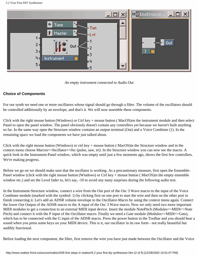
Have a look now at the Instrument-Panel window. You see a bunch of knobs that are wrapped up with frames to form groups. Each frame corresponds to one of the macros that we have inserted, so we know exactly which controller belongs to the Filter, which to Oscillator2, etc.
Now you can start polishing the panel design. For example, at the moment the controllers for Oscillator2 are still hiding those for Oscillator1. To change this click the left mouse button on the label Oscillator2 at the top of the frame, keep it pressed and drag the Oscillator2 block to some part of the window that you regard as suitable. You can do the same for all the other functional blocks.
Once you are happy with the layout you can freeze it in its current state to make sure that knobs or frames aren't ever moved in advertently. You achieve this by simply clicking on the padlock icon in the Instrument-Panel Toolbar.
Saving
You probably want to save the synthesizer you have built so that it isn't lost. Click on the disk icon (representing Save As...) in the Toolbar of the Instrument-Panel. With this function you do not save the whole ensemble (which you could do using the File menu) but only the instrument. This allows us to reuse the instrument in a future ensemble.
In the file dialog window that appears, choose a folder in which you like to keep your instrument, specify a file name and click on Save. When you are asked later whether you want to save the ensemble, you can say NO because the only part of the ensemble that's worth keeping (the instrument) has already been saved separately.
Luxury
In case you start to feel like adding more features after some time of playing around with your new synthesizer, rest assured that REAKTOR isn't going to limit your urge for experimentation. Just take a look at the macros which are included in the demo. You will find a lot of possibilities to transform this simple synthesizer into a luxurous sound machine.
http://www.reaktor.front.ru/source/reaktor3/05 first steps in reaktor/5.2 your first diy synthesizer.htm (5 of 5) [12/28/2002 10:01:07 PM]

5.3 Your First Self-Made Structure
Click here to show toolbars of the Web Online Help System: show toolbars
5.3 Your First Self-Made Structure
Our first synthesizer project was executed mainly using macros in which very many functions were pre-built. We would now like to introduce you to the art of constructing a synthesizer completely from scratch. This job is carried out at REAKTOR'S lowest level, the Structure. Contrary to the recommendation we gave above, which was to always to separate larger functional units into macros, this synthesizer will be constructed entirely within the instrument. The main reason for this is the fact that our new device will be of a quite modest nature It will consists of so few components that any further subdivision into macros would probably cause confusion rather than make things clearer.
Building the Basic Structure
Select the entry New form the File menu. The ensemble window now has just an Audio-in and an Audio-Out module. Again, take an empty instrument module from the library (click with the right mouse button (Windows) or Ctrl key + mouse button ( MacOS) in the ensemble window: lnstruments=>New=>Out1) and connect it to Audio-Out L and R.
Open the Structure window by clicking with the right mouse button (Windows) or ctrl key + mouse button ( MacOS)on the Instrument module and selecting Structure in the context menu. We will now implement the synthesizer circuitry in the Structure window.
First we create an oscillator. Our choice this time is a specimen that generates a triangle as its waveform. So: click with the right mouse button (Windows) or ctrl key + mouse button ( MacOS)in the Structure window, choose Modules=>Oscillator=>Triangle - done.
The next step is to create the elements that will tell the synthesizer about the arrival of notes (gate) and which key it was that was pressed (pitch). To that end, again open the context menu of the Structure window with the right mouse button (Windows) or ctrl key + mouse button ( MacOS)and select Modules=>MIDI Gate and then Mod-ules=>MIDI=>NotePitch. For the envelope we choose an ADSR module (Modules=>Envelope=>ADSR).
Now position and interconnect the modules according to the following illustration. The controller modules for the inputs A, D, S and R of the ADSR module are created with the aid of the Create Control function, to be found in the port context menus (which you open with a click (right mouse button (Windows) or ctrl key + mouse button ( MacOS)) on the respective inputs).
http://www.reaktor.front.ru/source/reaktor3/05 first steps in reaktor/5.3 your first self-made structure.htm (1 of 5) [12/28/2002 10:01:19 PM]

5.3 Your First Self-Made Structure
How Does It All Work?
On studying this structure, the following functionality becomes apparent: The ADSR module generates an envelope whose shape is specified using the Attack, Decay, Sustain and Release knobs in the instrument panel window (keep it tidy!). The envelope is triggered by a rising signal at the gate input G, in our case generated by the press of a key. The pitch is determined using the NotePitch module and is passed to the oscillator through its P(itch) input.
You can already play this synthesizer, but you will very likely soon get fed up with the sound, because other than the volume envelope there's definitely nothing that can be adjusted. The whole thing becomes interesting when a filter comes into play.
Adding a Resonant Filter
To create our filter - a Multi-2-PoleFM filter to be precise - select Modules=>Filter=>Multi-2-PoleFM from the context menu of the structure window. Then connect Out of the Triangle module to In of the 2-pole filter module and the filter's output LP to the Out terminal.
Next, using the Create Control function, create the control elements for the filter parameters Frequency Cutoff) and Res(onance) to make the structure look something like the picture below.
Filter's Function
http://www.reaktor.front.ru/source/reaktor3/05 first steps in reaktor/5.3 your first self-made structure.htm (2 of 5) [12/28/2002 10:01:19 PM]

5.3 Your First Self-Made Structure
Play a few notes on your keyboard while at the same time changing the position of the knobs FCutoff and Reson in the Panel window. You are using FCutoff to set the filter's cutoff frequency. When utilizing the output LP (low pass) of the filter module, as done here, all frequencies above the cutoff frequency are removed. By using the other outputs of the Multi 2-PoleFM filter module it can also be employed as a band pass (BP) or high pass (HP) filter.
Reson sets the resonance of the filter. The larger the resonance value is chosen, the more the frequencies "around the cutoff frequency" are boosted.
Adding Key Tracking
Now play some low notes and then some high notes on your MIDI instrument and you will notice that the high notes sound relatively dull. This is because the filter operates at a fixed cutoff frequency. This means that no matter what pitch you play, the filter always removes all frequencies above the fixed cutoff frequency. So if you play a note whose frequency is above this cutoff, almost nothing will be heard. We can change this by matching the filter frequency to the respective note pitch. Simply connect the NotePitch module with a second wire to the P(itch) input of the filter module.
The filter's circuit is designed to add the control signal at the P input to the frequency control signal at the F input. The sum of the two then determines the filter's cutoff frequency. If you play some high notes they will sound as you would expect.
Adding a Filter Envelope
Finally, we also want to control the filter cutoff frequency with an envelope. For simplicity's sake we will let the existing ADSR module take over this task, too. If you wanted to have a more sophisticated synth, you could add a separate envelope module just for the filter. For the envelope to affect the filter cutoff we first need another component, an audio multiplier (Modules=>+ , -, X, /=>AudioMult2). Connect this module to Out of the ADSR module, to the controller FCutoff and to the input F of the filter module, as illustrated below.
Play a few bars and you will hear that the envelope now affects the filter's frequency. It works like this: The ADSR module outputs a control signal between 0 and 1. This signal is multiplied by the value of the controller FCutoff. When the envelope is at its maximum value (1), the filter's input F receives the value 1 x FCutoff = FCutoff. When the envelope reaches its minimum value, the signal at F is reduced to zero (0 x FCutoff =0).
The function that the controller FCutoff now performs is commonly known as "Envelope Modulation Depth". To take this into account in the display, open the controller's Properties dialog window by double-clicking on its module and change the label F Cutoff to Env Mod.
http://www.reaktor.front.ru/source/reaktor3/05 first steps in reaktor/5.3 your first self-made structure.htm (3 of 5) [12/28/2002 10:01:19 PM]

5.3 Your First Self-Made Structure
Recording the Sound
Now that you have programmed your own new sound, you may not want to play it in real time but to capture the signal and send it to a file. One reason you might wish to do this is to export it from the REAKTOR software and load it an audio sequencer or audio editor.
What you need for recording sound in REAKTOR is the Tapedeck module. You find it under Modules=>Auxiliary=>Tapedeck 1-Ch. Put it in the Ensemble window under the Audio-Out module and connect its input In to the output of the instrument. Now use Create Control on its R(ecord) input to make a button with which to start and stop recording.
All you have to do now is to press the button in the Ensemble Panel to switch on recording, then make some sound with your synthesizer and finally press the button again to stop recording. If you weren't happy with the performance just repeat the procedure to make another recording - the first one will be erased automatically.
When you have finished recording you can store the sound as a file in WAV or AIF format. Click with the right mouse button (Windows) or Ctrl key + mouse button ( MacOS) on Tapedeck 1 in either the panel or structure window and choose Export Audio....in the context menu that appears. Select a folder, give the WAV-file a name and press Save to complete the operation.
Recording into a WAV-file with the Tapedeck module
When you are finished using the Tapedeck, you can remove it by selecting Delete from its context menu. Alternatively, just click on the module (its label changes color) and press the Del key on your computer keyboard - same result.
Variations
http://www.reaktor.front.ru/source/reaktor3/05 first steps in reaktor/5.3 your first self-made structure.htm (4 of 5) [12/28/2002 10:01:19 PM]

5.3 Your First Self-Made Structure
Here are some more suggestions for modifications you could make to the structure we have just built:
• Try out the HP and BP outputs of the 2-pole filter module
• Replace the 2-pole filter module with a 4-pole filter module.
• Try out different envelopes.
• Add an extra envelope for the filter module.
So you have other ideas? Go ahead and try them. Always remember that, in contrast to working with hardware components, there's never any danger of breaking anything in REAKTOR.
However, surprises regarding the generated sound will probably occur now and then, so to protect both your speakers and your ears you should not initially set the level of your external amplification too high.
So, get cracking!
http://www.reaktor.front.ru/source/reaktor3/05 first steps in reaktor/5.3 your first self-made structure.htm (5 of 5) [12/28/2002 10:01:19 PM]

6 The "Transformator" Tour
Click here to show toolbars of the Web Online Help System: show toolbars
6 The "Transformator" Tour
Welcome to the Transformator Tour. In this chapter you learn more about using the sample features of Reaktor.
By buying REAKTOR you haven't just acquired one single sampler, you've bought a load of them. REAKTOR also provides you with resynthesis functions that extend way beyond the functionality of normal samplers. Thanks to its modular structure, it will allow you to build as complex or as simple a sampler as you like.
However, we don't think it's enough to just give you a set of building blocks. After all, you want to make music and not spend all your time soldering bits of synthesizers together! That's why we've put together a range of instruments and ensembles which you can use right away. Each instrument or ensemble has been optimized for a specific application. impaktor is particularly suitable for percussive samples, and using Simulator you'll be able to imitate acoustic instruments, etc. The instruments and ensembles all differ in their application, their complexity and the demands they place on your system's processor.
We would like to present some of our favorites during this tour. You'll find out what each instrument or ensemble is used for and what we had in mind when we designed them. Every now and then, we'll be taking a look behind the scenes to find out a little about the structure of the instruments. If you already know your way around REAKTOR, you'll be familiar with some of the concepts described, so feel free to skim through some sections.
● 6.1 Practicing with Diletant ● 6.2 Percussion with Impaktor ● 6.3 Playing instruments with Simulant ● 6.4 FM and WaveSets with Stimulant and Vibrator ● 6.5 Playing Samples like WaveSets using Diktaphon ● 6.6 A tour through samples with Loopo, Plasma and Kompressor ● 6.7 4Dex
http://www.reaktor.front.ru/source/reaktor3/06 the transformator tour/06 the transformator tour.htm [12/28/2002 10:01:21 PM]

6.1 Practicing with Diletant
Click here to show toolbars of the Web Online Help System: show toolbars
6.1 Practicing with Diletant
First of all, make sure the input instrument you're going to be playing (the master keyboard or MIDI workstation) is connected to the computer's MIDI input, and that it was activated in installed Ports in REAKTOR. The MIDI output channel should be set to 1 on your input instrument. You can also use the QWERTY keys on your computer keyboard to play notes (see section Key Commands on page 180). If your MIDI connections are working properly, the MIDI LED in the top line of the Toolbar window will flash whenever you play a note.
In REAKTOR, open the Ensembles\Transformator Tour directory using File Open.... Select the Diletant.ens file located there and click on Open. You can now hear any notes you play on your keyboard. If you don't hear anything, check to see if REAKTOR is switched on. If it is, do the in and Out level meters in the Toolbar have a green background? If they don't, is the background of the in and Out meters gray? You can turn audio output in REAKTOR on and off at any time by pressing the main switch or by pressing the 0 key on your computer keyboard's numerical keypad.
In the Diletant - Panel window, you'll see a row of controls. The four knobs are for controlling an envelope which you can use to alter the volume of a note over time. You'll notice that if the Attack and Decay values are small, the sound has a more percussive character. We don't want to bore the synthesizer experts amongst you with a detailed explanation of the ADSR envelope, so please take ;i look at the Module Reference if you want further information. The library contains detailed descriptions of all components discussed during the tour.
Diletant panel
Let's take a look at the Sampler control that is positioned to the left of the envelope. This field represents the module in Diletant responsible for playing samples. It displays the name of the currently loaded sound and allows you to load other sounds. The simplest way to do this is using the Load Sound... item in the file menu (you'll first have to select the Sampler control). This menu item can also be accessed from the context menu by clicking the right mouse button (Windows) on the Sampler control or by clicking on the Sampler control while holding down the ctrl button (Mac). A standard File Open
http://www.reaktor.front.ru/source/reaktor3/06 the transformator tour/6.1 practicing with diletant.htm (1 of 4) [12/28/2002 10:01:24 PM]

6.1 Practicing with Diletant
dialog box will appear and allows you to select WAV, AIFF or MAP files. WAV or AIFF sound files contain only one single sample while a Map contains a collection of samples together with MIDI keyboard key allocations, etc. The piano simulation that is loaded when you open Diletant is based on a map. Besides a large number of AIFF format sound files, the supplied sound library also contains MAPs that are used to organize these samples.
By double clicking on the Sampler control, you can access the sampler module's Properties dialog box. You can use it to change or create new maps. Furthermore, the dialog box contains a range of switches used to influence the playback of samples, e.g. playback quality and direction, and various loop options. We don't want to go into detail here (the sampler dialog boxes and their options are dealt with in detail in Chapter 15) especially when you consider that most of the options are best understood if you just experiment with them. A basic rule of thumb is that the left half of the dialog box refers to global characteristics which affect the whole sampler module. The playback quality, for example, simultaneously affects all the samples loaded into this module. The right half of the dialog box refers to one sample at a time, i.e. the one selected in the Sample Map. So this means you can set the playback direction of the selected sample independently of the other loaded samples. If you want to effect a global change (you want all samples to behave in the same way as the one just selected) click on the Apply to all Samples in Map button.
http://www.reaktor.front.ru/source/reaktor3/06 the transformator tour/6.1 practicing with diletant.htm (2 of 4) [12/28/2002 10:01:24 PM]

6.1 Practicing with Diletant
Properties dialog box of the Sampler module
So now you're in a position to play back any sample you want in Diletant. We're now going to construct an ensemble with Diletant. Let's turn to the Ensemble - Structure window by choosing the menu item Show Ensemble. Compared with the Diletant - Structure window, there are no controls here. Instead you'll see "boxes" wired together. The structures you see represent the logical structure of instruments and ensembles. The ensemble structure, for instance, represents all the instruments in your virtual studio and their wiring. It's here that you'll find, among other things, Diletant. You can confirm that this is exactly the same instrument that we were just playing around with by double clicking on the Diletant box - the Diletant panel appears. Let's return to the ensemble structure. You'll see a wire leading from the Diletant output (Out) to the Audio Out input. A basic principle is that outputs are located on the right-hand side and inputs on the left-hand side of "devices". That's why we generally build structures from left to right. Try cutting the connection from Diletant to Audio Out by first selecting and then deleting it. Don't be surprised if you don't hear anything anymore. Now copy Diletant by selecting it, choosing Copy from the Edit menu and then Paste. Move the second Diletant anywhere you like within the structure. Double click it to jump to the second Diletant's panel which is positioned directly above the first. Arrange the panels so you can see both of them fully. Load any other sample or map you wish into the second Diletant. In the Ensemble - Structure window, connect it to the Audio Out by drawing a line from its output to one of the Audio Out's inputs. You'll now be able to play and hear the new Diletant.
We now want to hear both Diletants simultaneously. If you are working with a multi-channel I/O card, you'll probably want to lead both Diletants to separate outputs - that's easy to implement. If you want to internally combine both into one input, you'll need an adder for the output signals of the two instruments. We could also use a "proper" mixer, but we don't really need to do that here. In the context menu of the ensemble structure window you'll see a Modules submenu. This contains a +, -, X, / submenu. Select the Audio Add 2 item. An adder module will appear in the Ensemble-Structure window. Connect each of the two Diletants to an adder input and connect the adder output to one of the Audio Out inputs. You can now hear both Diletants simultaneously as a "layer". You can of course assign the instruments to different MIDI channels and note ranges. In order to do this, select an instrument in the structure window or simply select the instrument panel. The lower Toolbar (which always refers to the currently selected instrument) contains a button with an icon depicting a hand holding out a form. Select it. This is the Instrument Properties Dialog Box
containing the various instrument settings options. We won't go into detail here on the dialog box, but if you want to know more take a look at section 10.5.
http://www.reaktor.front.ru/source/reaktor3/06 the transformator tour/6.1 practicing with diletant.htm (3 of 4) [12/28/2002 10:01:24 PM]

6.1 Practicing with Diletant
Structure with two Diletants
Create as many Diletants as you wish and connect them all to the audio output. When you do this you'll see that the number displayed next to the main switch in the upper row of the Toolbar increases. This number represents the load on the processor in percent. Each instrument requires a certain amount of the processor's processing time. To be more precise, each voice of each instrument requires a certain percentage of the processing capacity. The left of the two number fields in the lower row of the Toolbar displays the number of available voices in the currently selected instrument. You'll see how the processor load changes when you change the number of voices in Diletant. Maybe you've already come across a dialog box warning you that the processor is overloaded. If this warning appears, REAKTOR turns off the main switch.
Depending on how powerful your computer is, you may have to keep an eye on the number of voices you use, and/or the complexity of your instruments. A basic principle here is: every instrument must be allocated a fixed number of voices, however, this does not need to be done for every sample. An instrument can play many samples in the form of a Sample Map. The voices available in the instrument are distributed as required to the samples in the map.
Of course you can play any instrument in the ensemble that you like. The techniques that we tested using the little Diletant example are also available to you in the following considerably more interesting instruments. All these instruments can be combined in the ensemble in any way you wish as long as sufficient processor capacity is available. By the way, effects such as chorus, phaser and reverb are also instruments. In the Ensemble-Structure context menu you'll find an instruments submenu containing an Effects submenu. Use this to open some effects and connect them between the outputs of your samplers and the inputs of the Audio Out module.
http://www.reaktor.front.ru/source/reaktor3/06 the transformator tour/6.1 practicing with diletant.htm (4 of 4) [12/28/2002 10:01:24 PM]

6.2 Percussion with Impaktor
Click here to show toolbars of the Web Online Help System: show toolbars
6.2 Percussion with Impaktor
Using File Open..., open the Impaktor.ens ensemble contained in the Ensembles\Transformator\Tour directory. Impaktor is our example of a drum sampler. As far as pure sample playback is concerned, Impaktor hardly goes much further than Diletant. Just like Diletant, it plays back samples in fantastic 32-bit quality with adjustable interpolation quality. The great thing about Impaktor has more to do with its frills. We've fitted it with a filter section which not only removes signal components but also adds them if required. This filter gives any dull sample the necessary impact.
Apart from that, Impaktor stands out in particular with regards to its simplicity. We've designed this instrument especially for playing back percussive sounds, so we've been able to do away with a load of controls, etc. that a universal sampler would normally need. For example, you won't find a Sustain control here because percussive sounds by definition have no sustain phase. It's not only the fact that instruments can be very complex which makes a modular system advantageous. Just as important is the ability to build very simple instruments that are tailor-made for specific applications.
The easiest way for you to get an all-round overview of lmpaktor's audio capabilities is by trying out the ready-made Snapshots. A Snapshot is like a "photographic image" of the current control settings. In the bottom row of the Toolbar (which, as we've already mentioned refers to the currently selected instrument) you'll see a drop-down menu. The entries it contains refer to the snapshots. If you select one of them, you'll see how the controls on Impaktor's panel re-adjust themselves. By the way, pressing the button to the right of the drop-down menu, will allow you to access a dialog box used for creating and deleting Snapshots. Snapshots can also be accessed simply using MIDI program change commands. Let's "read" Impaktor's panel from left to right.
The panel of Impaktor
Above the familiar Sampler control - which is used to access the Properties dialog box of the basic Sampler Loop sampler module -you'll find a framed Key Shift control. The value that is set here is added to the note number of the incoming MIDI note commands. At Key Shift = 12, Impaktor behaves in exactly the same way as for Key Shift = 0 if you play an octave
http://www.reaktor.front.ru/source/reaktor3/06 the transformator tour/6.2 percussion with impaktor.htm (1 of 4) [12/28/2002 10:01:27 PM]

6.2 Percussion with Impaktor
higher. Next to it you'll see a frame labeled Pitch. This contains controls that regulate the pitch of the sampler. You're probably asking yourself what the difference is between Key Shift and Transposition? Doesn't Key Shift belong in the Pitch frame as well?
In general, you don't just load one sample in Impaktor but a Sample Map. The sample map is a set of sample allocations to the various ranges of a MIDI keyboard. The idea is to allow you to access a large number of sounds using the keyboard. We don't necessarily want to use a separate MIDI channel for each percussion instrument, and besides, it is practical having a whole drum set spread across the keyboard when you're composing rhythms. Since less than 128 samples are generally used, there's a set of MIDI notes left over which can be used for transposing samples.
The MIDI note number therefore has two functions. Firstly, it determines which sample should be used from the map and secondly, it sets the transposition of the sample. The range of transposition across MIDI notes is obviously more limited the more samples are contained in a map. In order to get around these limitations, we've given Impaktor the Transposition control. This merely alters the transposition - the selection of samples from the map remains unaffected. The remaining Pitch controls are used to control the pitch envelope. You can see how they work by experimenting. Now let's take a look at the Filter section. Cutoff and Body define the basic settings of the filter. The Cutoff frequency of a filter determines which range of the spectrum is suppressed by the filter. Since the first level of the Impaktor filter is set up as a lowpass, this means that high frequency signal components located on the other side of the Cutoff frequency are suppressed. The Vel control allows you to modulate the cutoff frequency using key velocity. The Mode switch determines how the filters are connected. In the LP setting, the incoming signal is lowpass filtered, in the BP (bandpass) setting a highpass filter is added to the lowpass so that only one frequency band passes through the filter. The Body parameter above the Mode switch is only of relevance in the BP setting; it sets the cutoff frequency of the highpass filter and therefore determines the width of the frequency band that can pass through the filter.
We've given this parameter a made-up name because in Impaktor the actual cutoff frequency of the highpass filter is set with dependence on the cutoff frequency of the previously connected lowpass filter. Why? Because we like it that way! We tried out many things and came to the conclusion that this kind of dependency makes sense and that a Body control actually belongs on the front panel of every synthesizer. The nice thing is that you don't have to agree with any of this. You're about to find out how you can get around these kinds of customizations.
However, let's first take a look at the Dirt parameters in the Impaktor filter section. You can chose between two types of "dirt", or simply leave the signal clean. The Dirt control allows you to set - using a subjective scale - the amount of dirt you want to have added to the signal. Both Dirt variations are distortion effects, and the distortion level is principally switched between lowpass and highpass. Why is that? Yet another customized setting! Did you buy a piece of modular software just to have control taken away from you? No doubt you have already double clicked angrily on the Filter label of the frame surrounding the filter section.
http://www.reaktor.front.ru/source/reaktor3/06 the transformator tour/6.2 percussion with impaktor.htm (2 of 4) [12/28/2002 10:01:27 PM]

6.2 Percussion with Impaktor
The structure of the filter section in Impaktor
A new window entitled Filter - Structure appears. We've already dealt with structures when we combined Diletants with one another in Ensemble - Structure. The structure that we now see displays the "innards" of the Impaktor filter. You can trace the signal from the signal input (in) to the output (Out). Apart from that you'll also see representations of some of lmpaktor's controls, such as Cutoff at the very top. Now you can change some of the wiring so that, for instance, the Dirt distortion unit is connected at the end of the chain.
We've changed the position of the distortion unit in the signal stream, but we still don't know anything about its insides. Let's open up this little black box by double clicking on Dirt. The Dirt - Structure window that then appears confirms our suspicions that Dirt contains two separate distortion units which can be selected using a switch. However, our thirst for knowledge has not yet been quenched. We double click further into the innards of Pitch. Take note of the in, ln2, Dirt and Out connections represented as little boxes. As you can see, a signal is added to the input signal. This added signal comes from a separate ln2 input and travels through a Differentiator and a Rectifier. What goes on in the Rectifier? Up till now, if we wanted to find out the answer to that sort of question we'd simply double click on the Rectifier module But instead of a new Structure window appearing as before, we now see a dialog box entitled Rectifier - Properties Although this allows us to see what a Rectifier does, we cannot see how it does it
There is no harm in having a few secrets Rectifier is - in REAKTOR terminology - a Module while Pitch, Dirt and Filter are so-called Macros Modules are the smallest, indivisible processing units Macros are combinations of modules and other macros You'll be familiar with these kinds of hierarchies from your computer's file system REAKTOR Macros correspond to the directories that contain both files and other directories Double clicking on a directory symbol in Explorer™ or Finder™ will open that directory just as a double click on a REAKTOR Macro reveals its insides
Let's "zoom out" again from the detailed level of the distortion circuits back to the structure of the Impaktor filter by closing the Pinch and Dirt structure windows How do we go to a level deeper from here? The Windows menu contains the Goto
http://www.reaktor.front.ru/source/reaktor3/06 the transformator tour/6.2 percussion with impaktor.htm (3 of 4) [12/28/2002 10:01:27 PM]

6.2 Percussion with Impaktor
Parent menu item Select this item You'll now see the Impaktor - Structure, i. e. the inner structure of Impaktor You'll recognize the Filter macro that we've just seen from the inside as well as a whole range of other macros and modules Any guesses what will happen when we select the Goto Parent item from the Windows menu in Impaktor - Structure? Yes, that's right, you're taken to the Ensemble - Structure Is Impaktor a Macro as well? Actually, it's more than that Impaktor is an Instrument, and Instruments are high-level Macros They have their own MIDI settings and, in particular, their own Panel By taking a look at the Impaktor - Panel you'll see that the macros visible in the Impaktor - Structure also appear in the Impaktor -Panel as frames
Now we know everything about Panels, Structures, Ensembles, Instruments and Macros, and you can move anywhere you want within their hierarchy to find out how a circuit is structured or to change it The number of basic concepts behind REAKTOR is small - its power lies in the hierarchy
Let's end our journey through the insides of Impaktor What else does the Impaktor - Panel have to offer? Nothing very exciting, really From our dealings with the Pitch macro we are already familiar with the envelope in the right-hand area of the filter section The filter envelope works in exactly the same way as the pitch envelope The Amp section deals with amplification and attenuation of the signal, or in plain English, making it louder or quieter There is also the basic setting, Gain, with Vel modulation and an envelope that goes over and above the simple Decay type that was used for Pitch and Filter Decay and Release are two parameters that influence the fading out of a note Decay affects the note for as long as the key remains pressed down, the Release parameter sets the fade out after the key is released If you set different values for Decay and Release, you can create interesting articulation for your percussion sounds using the note duration
A final point regarding Impaktor a series of switches is used which, among other things, provide an Off position So, for instance, you can use them to cut out the whole filter section This is not only a handy option, it also saves on processing capacity - take a glance at the load display in the Toolbar to convince yourself
http://www.reaktor.front.ru/source/reaktor3/06 the transformator tour/6.2 percussion with impaktor.htm (4 of 4) [12/28/2002 10:01:27 PM]

6.3 Playing instruments with Simulant
Click here to show toolbars of the Web Online Help System: show toolbars
6.3 Playing instruments with Simulant
Let's take a look at the Simulant ens ensemble in the Ensembles\Trans-formator Tour directory Simulant is a universal sampler which - as opposed to Impaktor- is also very well suited for non-percussive sounds Using Simulant you can also play stereo multi-samples (e. g. recordings of acoustic instruments) with great "expression" on a MIDI keyboard. To facilitate this, we've provided a range of modulations. Again, we've taken care to keep the design compact to ensure the instrument maintains a clear appearance.
The panel in Simulant
The Selection section deals with the selection of a sample from the sample map at the start of a note. Usually, the note number of a MIDI note command determines two things: firstly, which sample should be played from the map, and secondly, what transposition of the sample is required in order to output the desired pitch. Simulant allows you to decouple these two functions from one another. If the Tracking switch is deactivated, the selection of samples from the sample map is completely decoupled from the note number and is then only determined by the Shift input. Under normal circumstances, such as when Tracking is active, the sample selection can be influenced using the Shift control. For example, if Shift is at 12 (i.e. "one
http://www.reaktor.front.ru/source/reaktor3/06 the tr...rmator tour/6.3 playing instruments with simulant.htm (1 of 3) [12/28/2002 10:01:30 PM]

6.3 Playing instruments with Simulant
octave") and we play C4, a sample will be played that would normally only be played by C5. This substitution does not affect (in the case of normal multi-samples) the pitch that is heard but it does influence the timbre. Since high notes normally have a strong high-frequency spectral component, the C4 that is played sounds brighter than usual. This affects not only brightness but also in the case of a piano multi-sample, detunes the harmonics which differ for higher and lower notes. In order to articulate this sound effect well, a dependency on key velocity can be created using the Vel parameter.
Next to the Selection section, you'll see the Position section. Here you can set at what point the sample playback begins when a note is played. The Start control sets a basic setting. When set to 0, the sample starts from the beginning. The closer the Position value gets to 1, the further back in the sample playback will begin. The Vel control determines how strongly the starting point depends on the key velocity. Let's assume we're playing a flute sample. The sample starts with a blowing sound which turns into a stationary phase at the point where the sample loop is positioned. An idea might be to "reveal" more or less of the beginning of the sample depending on the amount of key velocity present. Notes played gently only output the "boring" stationary phase, while pressing down hard on the key will ensure that the turbulent breath sounds before the stationary phase are also played. The Vel control is fitted with an appropriate scale: if Vel is set to 0.5, a note played with the minimum of key velocity will start in the middle of the sample. With medium key velocity, playback begins after the first quarter of the sample. The sample can only be heard from the very beginning if the note is played with the maximum key velocity.
The Single Trig(ger) switch activates an operating mode that is actually only of use for monophonically played sounds. If the switch is set to On, samples and envelopes will only start when a note is played if no other note is still being played. If you are playing using a legato style, the re-triggering of samples and envelopes is suppressed; the pitch of the note that was played last is simply perpetuated. The Single Trig(ger) mode is obviously only of use for long samples or samples with activated sample loop.
In the Pitch section you'll see subdivisions which are depicted as frames within frames. We've already learnt about the concept of Macros in connection with Impaktor. What we're seeing here is the Panel representation of nested Macros. The Glide macro is used to produce portamento effects: the pitch transfer from one note to its successor is smoothed over time. The rate that controls this is the Speed parameter. The glide effect is primarily of interest when playing monophonic sounds Glide is very useful when used in combination with the Single Tng(er) mode, which is why both their switches are positioned close to one another
Pitchbend offers two settings options In Cnt (Continuous) mode, incoming MIDI pitchbend commands affect all the notes that can be heard equally - this is of course to be expected from a channel-related MIDI command In S&H (Sample & Hold) mode on the other hand, the current pitchbend position is queried for every note-on command and is then maintained for the entire duration of the note This option is particularly useful when used with percussive sounds, such as "drum maps", when you don't want to bend the pitch of every drum that is currently sounding In this case, we want to detune the sample from the very beginning of the note
The pitch Env(elope) is very similar to the one we've already come across in Impaktor The intensity of the envelope modulation can be made dependent on key velocity using the Vel control The pitch LFO (Low Frequency Oscillator) produces different types of vibrato The intensity of this modulation can be controlled using standard methods, like using the modulation wheel (MIDI Continuous Controller 1) By the way, the LFO frequency set at the Freq(ency) control differs from the actual frequency by a maximum of ten percent This inaccuracy has been integrated intentionally in order to avoid the LFOs acting identically for all the voices These kinds of tricks are necessary to break up the rigidity of digital techniques, since rigidity is not always desired The curious among you can investigate the details of the LFO structure using already familiar investigation methods
The Filter section of Simulator largely corresponds to that of Impaktor However, it does of course have a "double" structure internally since Simulator supports the use of stereo samples The Tracking parameter, which also appears in the otherwise unspectacular Amp section, is used to adjust the filter cutoff frequency (or amplification) to suit the pitch A negative
http://www.reaktor.front.ru/source/reaktor3/06 the tr...rmator tour/6.3 playing instruments with simulant.htm (2 of 3) [12/28/2002 10:01:30 PM]

6.3 Playing instruments with Simulant
Tracking of amplification can be useful to compensate for the drop in level experienced in strongly downwardly-transposed samples
http://www.reaktor.front.ru/source/reaktor3/06 the tr...rmator tour/6.3 playing instruments with simulant.htm (3 of 3) [12/28/2002 10:01:30 PM]

6.4 FM and WaveSets with Stimulant and Vibrator
Click here to show toolbars of the Web Online Help System: show toolbars
6.4 FM and WaveSets with Stimulant and Vibrator
You'll find the Stimulant ens ensemble in Ensembles\Transformator\ Tour Stimulant is a descendant of Simulant, or to be more precise, an extension From first appearances you can see we've added the FM section FM stands for frequency modulation, which became a very popular sond synthesis technique in the 1980s Using FM, you can create very complex and rich sound spectra with a minimum of processing power As is usually the case, when talking about FM we are dealing with a combination of several oscillators, i e elemental oscillation generators A difference is made between Modulators and Carriers The output signal of a modulator controls (modulates) the frequency of a carrier which, in principle, is no different from a vibrato circuit The difference is that both modulators and carriers oscillate in the audio range and that the frequency is modulated in a linear manner, i e on a Hertz scale Pitch modulation in the sense of vibrato would best be implemented using a logarithmic (semitone) scale This is because we want the maximum negative deflection of the pitch from the zero position to have the same musical interval as the maximum positive deflection If this is not the case then the pitch you hear will be somewhat off
Simple mathematical rules apply for frequency modulation These were published by John Chowning in the 1960s in the most famous article on computer music Using these rules (which we aren't going to go into here since they're not that simple) you can calculate which sidebands would be produced at what amplitude during modulation Sidebands are partial tones whose frequencies do not necessarily have to be in a harmonic relationship with the frequency of the carrier or of the modulator Harmonic sidebands are, in fact, an exception
So what's any of this got to do with sampling? Well, we can build the oscillators, which are connected to FM carriers and modulators, simply out of samplers What happens if we set the loop length of a sample to a very small value? We get a periodic wave like a sound generated by an oscillator That's exactly how we have created a sine wave oscillator in Stimulant In the structure of the FM macro you'll see a macro called Sine This macro contains a Sampler module which acts as an oscillator; and the sampler itself contains a sample. Using the Edit command (in the sampler module's Properties dialog box) you can load and examine this sample in your sample editor. The sample consists of exactly one sine oscillation. The Oscillator Mode option in the sample module's Properties dialog box is activated. When set to oscillator mode, the sample module assumes that the length of the sample loop (or the length of the sample if no loop is set) corresponds to one period of the yet-to-be synthesized oscillation. Accordingly, the repeat rate of the sample is set depending on the desired pitch. So now we have an FM modulator.
A Sampler Loop module acts as the carrier. This module has already been responsible for sample playback in Simulant. The only difference is that the F input of the module is also connected. What we're doing is frequency modulating a sample. In principle, this is nothing other than "normal" frequency modulation except for the fact that our carrier generally contains a complex waveform. After all, any audio material can be packed into a sampler. This provides us with the interesting situation where a large part of the complexity normally achieved in an FM synthesizer (by cleverly connecting a whole series of modulators and carriers) is already "contained" within the carrier. The advantages are obvious: we can start by using our existing and familiar material and we only have to invest a little time and effort in order to create very complex and rich sounds. Of course, our use of one sine wave modulator and one sample carrier is only one of an infinite number of possibilities. This particular configuration is especially useful, since control over the resulting sound is quite effective.
http://www.reaktor.front.ru/source/reaktor3/06 the tr...r/6.4 fm and wavesets with stimulant and vibrator.htm (1 of 2) [12/28/2002 10:01:33 PM]

6.4 FM and WaveSets with Stimulant and Vibrator
The panel in Vibrator.
Now take a look at Vibrator. Obviously we're not dealing with sampling here, i.e. processing sound recordings in the narrower sense. Instead, with Vibrator we are closer to dealing with a combination of a WaveSet synthesizer and a FM synthesizer. (Native Instrument's WaveSet Synthesis is similar to what other manufacturers call Wavetable Synthesis or Transwave Synthesis, but many soundcard manufacturers also use the term Wavetable Synthesis for simple ROM sample playback.) You may be surprised though at the similarity on the structural level with Stimulant and other sampler instruments. In the structure of the Wave macro (located on the very left of the instrument's Panel), you'll see two identical WaveSet macros. Inside each of the two WaveSet macros you'll see - surprise, surprise - a Sampler Loop module whose F input is connected and is therefore also acting as an FM carrier. Take a look at the Properties dialog box of the sampler module. The module has a series of loaded samples. If you open them using your sample editor, you'll notice that they look quite artificial. This is not what an acoustic instrument sounds like! Actually, these WaveSets were produced synthetically at Native Instruments. If you listen to the WaveSet samples in the sample editor you'll notice they are very short How does Vibrator manage to delay the end of the sample so long? A WaveSet is a series of periodic waveforms When we dealt with Stimulant we talked about how a Sampler module can be used for playing back periodic waveforms The Sampler Loop module extends the Sampler module by (among other things) one input (LS) You can use this input to position the loop within a sample (i. e. set the loop starting point) When the loop length corresponds to the length of a period in the WaveSet sample (as you can see in your sample editor, the loop length has been set accordingly), you can "run" the various waveforms that are stored in the WaveSet sample by applying different values to the LS input If you trace back the origins of the signal entering the LS input, it becomes clear that in Vibrator, the key velocity and an envelope also determine the position in the WaveSet besides a fixed value The loop starting point should always coincide with the beginning of a waveform in the WaveSet Luckily, the Sampler Loop module sorts these details out for you automatically when running in Oscillator Mode
http://www.reaktor.front.ru/source/reaktor3/06 the tr...r/6.4 fm and wavesets with stimulant and vibrator.htm (2 of 2) [12/28/2002 10:01:33 PM]

6.5 Playing Samples like WaveSets using Diktaphon
Click here to show toolbars of the Web Online Help System: show toolbars
6.5 Playing Samples like WaveSets using Diktaphon
Please open Diktaphon ens As you can see, Diktaphon's panel is similar to Vibrator's In fact, what we're dealing with here is also a type of WaveSet synthesizer The special thing about it is that no specially constructed synthetic waveforms are being processed here, instead they're just very normal samples By default, Diktaphon loads a speech sample the word "TRANSFORMATOR" The sample has not been electronically altered, even though many of you may think it has (rather, the speaker comes from Bavaria)
Instead of the Wave section that appears in Vibrator, we see the Position section appearing here in Diktaphon It fulfils largely the same function You can use it to set which part of a sample should be used for synthesis Try moving the slider control while playing some notes in order to hear the various sounds of the word "TRANSFORMATOR" Again, an envelope and key velocity can be used to modulate the position The filter section in Vibrator has been replaced by the Formants section in Diktaphon If you take a look in Diktaphon - Structure you'll see that no filter has been used, the settings in the Formants section affect the F(ormant) S(hift) input of the Pitch Former module that is used for synthesis What we're dealing with here is one of Pitch Former's specialties it can shift the formants of the sound within the spectrum without affecting the fundamental pitch - and vice-versa What are formants9 Briefly, formants are elevations within a sound's spectrum whose positions are independent of the sound's fundamental frequency Formants play a role, for instance, when identifying spoken sounds Furthermore, the position of the formants is different for men, women and children
If you switch off both LFOs and set the envelope intensity in the Pitch section and in the Formants section to zero, you'll hear an unmodulated synthetic sound Any melody in the voice of the sample will have disappeared Pitch Former "removes" the pitch characteristics from any sample and forces any other pitch that you want onto it
http://www.reaktor.front.ru/source/reaktor3/06 the trans...ur/6.5 playing samples like wavesets using diktaphon.htm [12/28/2002 10:01:35 PM]

6.6 A tour through samples with Loopo, Plasma and Kompressor
Click here to show toolbars of the Web Online Help System: show toolbars
6.6 A tour through samples with Loopo, Plasma and Kompressor
Please open Loopo ens Loopo behaves like a "normal" sampler and is largely identical to Simulant The advantage with Loopo is that it takes care of finding the best loops for you It saves you having to adjust loop points in a sample editor All you need do is simply load your sample(s) in Loopo and, using the Loop control, set the position where you roughly want to have the loop You can play notes while you're doing this thus allowing you to "push" the loop through the sample during playback
Instead of the Sampler Loop module, which you're familiar with from Simulant, a Resynth module is used in Loopo The way a normal sampler like Sampler Loop functions can be easily described using analogies with analog studio techniques However, that's not so simple when dealing with Resynth A normal sampler plays a sound recording like a cassette player Changes to the pitch are achieved by playing the sample more quickly or slowly This means that pitch is always directly linked to speed Resynth, on the other hand, "cuts up" the sample into small particles and reassembles them ready for playback As far as Loopo is concerned, up to the point in time when the configured loop point is reached, the particles are simply put back together again in exactly the same order as they appear in the sample material You cannot tell the difference between the result of this process and "normal" sample playback However, as soon as the configured loop point is reached, Resynth starts repeating the same little sample slice over and over again Note that the loop Length parameter is set to zero The sound that you hear after the loop point has been reached is not a normal sample loop, but a sound particle that is continuously repeated by Resynth You're probably asking yourselves, "What's the difference between a normal sample loop and this sequence of particles9" Each particle is fitted with micro-envelopes before being sent to the output These micro-envelopes ensure that crackling sounds are prevented during the transfer from one particle to another Furthermore, no gaps are allowed to form between consecutive particles The particles "crossfade" from one to another, so to speak That's why the loop always sounds smooth
The feature where the optimum loop is automatically searched for by Loopo only works well for sounds which have a unique pitch However, as we know, sounds without a unique pitch are difficult to loop anyway As we've already demonstrated with Vibrator, you can consider the sample loop as one period within a periodic oscillation If you want to loop a periodic sound, you should configure the sample loop in such a way that it includes one or more periods of the sound material This means you have work out the signal period, a task normally carried out for you automatically by Loopo No sound in the "real" world is periodic in the mathematical sense of the word, and the signal period enclosed by a loop will start sounding pretty rigid after a while That's why Loopo provides you with an LFO section that you can use to vary the pitch This will take away the rigidity of loop playback Loopo can only set up loops in an optimum manner if Signal - informed Re-Synthesis is activated for the affected sample You can access this option in the Module Properties dialog box If the option is selected, the resynthesis process adjusts itself to suit the characteristics of the sample material In order to do this, an analysis is carried out when the sample is imported This may take some time to complete but it only need be carried out once (the analysis results are stored in the sound file)
If the sample material has no unique pitch it therefore also does not have a unique period that can be used to "make" a loop In this case, anyone hearing the loop will notice this straight away In these kinds of difficult cases we have to come up with something a little more clever That's exactly what we did in our Plasma example Please open Plasma ens Plasma can generate sounds without any assistance from you - well, at least you should be able to hear an awesome sound develop
http://www.reaktor.front.ru/source/reaktor3/06 the...ough samples with loopo, plasma and kompressor.htm (1 of 3) [12/28/2002 10:01:37 PM]

6.6 A tour through samples with Loopo, Plasma and Kompressor
when you open and activate this ensemble By the way, the sound originates from a piece of rhythmic music The idea with Plasma is to take any sample you wish and freeze it in time at any point you wish Here are some examples
1 ) You hear a sound on a record that you like, let's say a chord sung by a choir You think, "That's just the choir sound I'm looking for' I'm going to sample it" The only annoying thing is that the chord is so short You try using a loop The loop is too short, it sounds tinny and unusable By simply looping it, you're taking away the liveliness from the sound, which was actually the reason why you sampled it in the first place
2 ) You've got to design a sound for a radio play or for post-scoring a film You've found a nice recording that you'd like to use as an "atmo" (background sound) Unfortunately, the recording is too short for the take Or else the recording is so nice that you want to use it all the time At some point you'd hear that it's Just the same sound over and over again - and that's embarrassing Plasma provides you with a range of controls which you can use to search for the position in the sample that you want frozen and to adjust the resynthesis process to suit the material.
The panel in Plasma
The controls in the Grains section affect the Resynth module. The most important parameter is Freq. It determines the granularity of the resynthesis process. At small settings, the Resynth module outputs relatively large "chunks" of the original signal; large values produce a rapid succession of very small sound particles. From the Grains structure, you'll see that the frequency values - which are interpreted as pitch in semi-tone steps - are converted in a macro called P to ms into a period in milliseconds before they reach the Gr(anularity) input of Resynth. This conversion only takes place because we found a logarithmic scale for this parameter to be more useful in Plasma. The Freq parameter is equipped - in the same way as the position in the sample - with a random generator that can be controlled using Random. You can use it to break up the regularity of the resynth process. If you set all the Random controls and the Stereofy control to zero, you'll hear the unmodulated resynthesized sound. This is the best way of testing the effects of changes made to the Freq parameter. Smooth has the effect that its name suggests. The higher this control is set, the "rounder" the resynthesis sounds. Stereofy
http://www.reaktor.front.ru/source/reaktor3/06 the...ough samples with loopo, plasma and kompressor.htm (2 of 3) [12/28/2002 10:01:37 PM]

6.6 A tour through samples with Loopo, Plasma and Kompressor
controls the intensity of a random modulation of the stereo position. Of course you can resynthesize stereo samples using Resynth; Stereofy nevertheless has an effect on the stereo base width.
The Pitch section has been kept basic. Besides a global transposition control, you'll also see a random fuzziness control. We don't need to say anything further on the Filter and amplitude settings. The Diffusion section is also useful. What we're dealing with here is a primitive reverb device which, in this case, is not used for spatial simulation. Instead we use it to "disperse" the resynthesized sound.
To be more precise, there are in fact two ways in Plasma to achieve greater diffusion: besides activating the diffuser, you can also increase the number of voices. The instrument bar of the Toolbar contains two small number fields on its right-hand side. The left one sets the number of voices allocated to the selected instrument. The right-hand number field displays the number of voices that are activated when a note is played. If this field contains the number "3", REAKTOR assigns three voices when a MIDI note is triggered. The voices play the note in unison. If the voices really were to do exactly the same thing as each other, you'd have the same result as with one voice but with three times the amplitude. However, since we're using a series of random modulations here, none of the voices acts in exactly the same way as the others. An increase in the number of unison voices usually goes hand in hand with a subjective feeling that the sound density has been increased.
If three unison voices are triggered when a note is played, how many voices should an instrument have in total in order to play three-voice chords? No, you don't need nine. REAKTOR distributes the voices that are available to an instrument in as "fair" a manner as possible among the notes that are currently being played - the notes played first are always given preference over the rest. Using this dynamic unison mode, you can achieve a subjective feeling of density - with instruments such as Plasma - that is independent of the number of notes currently being played. Naturally, unison is not only interesting when used with random modulation. You could increase the number of unison voices for nearly every instrument in order to achieve a "fatter" sound.
Now let's have a look at Kompressor.ens. We designed Kompressor specifically for percussive sounds. As opposed to Impactor, a Resynth-Sampler is used here. That's why we have some new exciting parameters: Period defines the period of the resynthesis algorithm and can be randomized with the Noise knob in order to eliminate tonal artifacts of the resynthesis. Real fun is the Time Warp section: Decay and Release define the readout speed of the sample. There is no need for an Amplitude Envelope anymore, the length of the sound is defined via a real time stretch, samples therefore can not only be made shorter but also stretched. To make things more complex we added the Warp Knob. This parameter defines the exact curve of the readout and is also influencing the pitch and filter envelope. This is complicated to explain but is very effective. Please keep in mind that a very important parameter is hidden in the Properties Dialog of Resynth. The sound will sometimes change drastically depending on the setting of the Signal informed Re-Synthesis switch.
http://www.reaktor.front.ru/source/reaktor3/06 the...ough samples with loopo, plasma and kompressor.htm (3 of 3) [12/28/2002 10:01:37 PM]

6.7 4Dex
Click here to show toolbars of the Web Online Help System: show toolbars
6.7 4Dex
The panel in 4Dex
Now open 4Dex.ens. 4Dex starts playing automatically. You don't need to connect a MIDI keyboard or external sequencer. You're probably a little surprised to see Ensemble - Panel - we haven't had anything to do with this yet. This panel is the counterpart to the familiar Ensemble -Structure window. In Ensemble - Panel, all the instruments of the ensemble are represented as sub-windows. In the Properties dialog boxes of all controls (i.e. faders, knobs, buttons, etc.), you can set whether you want each control to be visible in the instrument panels and / or ensemble panel. This means you can set up two different views for each instrument, whereby the ensemble view is usually a reduced version of the instrument view. The idea
http://www.reaktor.front.ru/source/reaktor3/06 the transformator tour/6.7 4dex.htm (1 of 2) [12/28/2002 10:01:39 PM]

6.7 4Dex
behind this is that you can put together a set of controls on the ensemble panel that you're going to need for making music. After all, when you're composing, you don't want to keep on having to swap views between different windows.
4Dex comprises four instruments which are based on sample playback. Deck 1 and Deck 2 play beat loops. Deck 3 and Deck 4 play individual drum samples that are triggered by a small sequencer. Each Deck has a Pitch control that alters the pitch of the samples independent of the centrally configured Clock rate. This is not really that much of a surprise as far as the simple sample players in Deck 3 and Deck 4 are concerned. However, it's quite a surprising feature to see in the beat-loop players in Deck 1 and Deck 2. You'll also notice that all the Decks are played in sync for any given central Clock rate. This is a special feature of the Beat Loop module that is used here. If you take a look at the structure window in the Sample section of Deck 1 or Deck 2, you'll notice a Beat Loop module with its C(lock) and Rst (Reset) inputs. If you trace back the origins of the signal entering the C input, you'll discover the Clock Osc module located inside the Clock macro that is positioned on the ensemble level. At every 96th of a note, this oscillator outputs a pulse that Beat Loop uses for synchronization. By the way, if the C input is not connected, Beat Loop automatically synchronizes itself with the global clock in REAKTOR. Beat Loop is connected in pretty much the same way as the sampler modules in REAKTOR which you are already familiar with. However, a special feature is that the St, LS, LL and SO inputs can only understand values presented as sixteenths of a note. This seems reasonable to expect since when we think about beat loops we think more in terms of musical counts than in milliseconds.
At the Ct16 output, Beat Loop outputs the number of sixteenth notes that have passed since the beginning (since switching on / reset). If you let 4Dex run a while, quite high values will start to accumulate. In the structure of the two Sekwenzor (Sequencer) units, you'll see a Demux module doing its job. Its Cnt input is connected to the Ct16 output of one of the two Beat Loops. The Demux module is "told" how many 16th notes have passed since being switched on and, using this information, works out where the current position of the sequence is in the rhythm. With this information, it then sends one of the 16 input events to its output which is in turn connected to the Trig(ger) input of a Sampler.
There is nothing to stop you now from starting further Decks which play other beat-loops or drum samples. You can just as easily construct your own Decks which for instance play a melody or, or, or...
We've now come to the end of our Transformator tour. We wish you all the best and a great deal of fun with REAKTOR!
http://www.reaktor.front.ru/source/reaktor3/06 the transformator tour/6.7 4dex.htm (2 of 2) [12/28/2002 10:01:39 PM]

7 Interfaces
Click here to show toolbars of the Web Online Help System: show toolbars
7 Interfaces
● 7.1 VST 2.0 ● 7.2 Windows Direct X Plug-in ● 7.3 ASIO ● 7.4 DirectConnect ● 7.5 MAS and FreeMIDI ● 7.6 MIDI File Player
http://www.reaktor.front.ru/source/reaktor3/07 interfaces/07 interfaces.htm [12/28/2002 10:01:41 PM]

7.1 VST 2.0
Click here to show toolbars of the Web Online Help System: show toolbars
7.1 VST 2.0
What is VST 2.0 ?
VST and VST 2.0 are software interfaces developed by Steinberg. VST, in the original version 1 of the interface, had been developed in order to be able to integrate real time effects as "plug-ins" into so called "host programs", which are usually MIDI/audio sequencers or sample editing programs. VST 2.0 additionally makes it possible to send MIDI data to compatible plug-ins and thereby allows the integration of native sound generators. The MIDI control via VST 2.0 is sample precise and allows absolutely precise timing during the playback of MIDI tracks.
Using VST 2.0 with REAKTOR
If you want to use REAKTOR as a VST 2.0 plug-in, you have to move the "REAKTOR host plug-in" into the VST plug-in folder of your VST 2.0 compatible host program. Then you can call and activate REAKTOR as any other VST 2.0 plug-in. Please read the respective information in the manual of your host program, since the installation and operation of VST 2.0 plug-ins is different in different host programs.
You will see that there are two different Reaktor plug-ins available in the VST host program: one for effects and one for VST instruments. The Reaktor plug-in for effects shows up in the host program like any other VST effect. The Reaktor VST instrument plug-in produces six mixer chanels in the host program: one stereo chanel and four mono chanels. These six chanels correspond to the first six ports on the Audio Out module in the standalone version of REAKTOR, so that you are able to make the appropriate routing there. Please note that it is possible to connect to ports which are marked with a green cross to show that they are inactive.
After calling the REAKTOR plug-in, an empty window appears into which you can load an ensemble of your choice by the File/Open... dialog. Under VST 2.0, two inputs and outputs can be used simultaneously for each REAKTOR plug-in or ensemble.
With VST 2.1-compatible sequencers (Cubase 5 for instance), you can send MIDI to effect plug-ins as well. Since Reaktor supports VST 2.1 you can set the output of a MIDI track to the plug-in when it is used as a send, an insert or a master effect.
Since VST 2.0 allows only one window for each plug-in, only the ensemble panel can be used as a user interface. Therefore all panel elements which you want to use should be visible in the ensemble panel and not only in the panel of the instrument. Of course invisible panel elements with activated MIDI remote control can be controlled during the operation as a plug-in, as well.
Obviously the restriction to a single window has a further consequence:
http://www.reaktor.front.ru/source/reaktor3/07 interfaces/7.1 vst 2.0.htm (1 of 2) [12/28/2002 10:01:42 PM]

7.1 VST 2.0
If you use an ensemble as a plug-in, you can not change its structure. In order to make such changes, the ensemble has to be opened with the normal (stand alone) version of REAKTOR. After changing the structure and saving, the ensemble has to be loaded into the plug-in again in order to activate the modifications. Changes which only affect the parameters of the ensemble (as new or changed snapshots) can be stored also if the ensemble is being used as a plug-in: The file menu of the plug-in window allows you to save the ensemble to disk like in the stand alone version of REAKTOR. You can also use this possibility to make copies of an ensemble or to update the reference path in the host document (see below). Since REAKTOR ensemble can get very big (due to embedded samples) it is not possible to make them a component of the host document. Consequently, an ensemble which is being used as a plug-in will not be saved as part of a song of a VST compatible sequencer. Only a reference to the path of the ensemble will be saved instead. In order to guarantee that a song can be reproduced later, copies of all ensembles which have been used with this song should be archived together with the song itself.
If you want to use the same ensemble with different settings within one song, it is necessary to make differently named copies of the respective ensemble and to archive them with the song. This is the only way to ensure that each plug-in slot has access to the ensemble with the corresponding settings.
http://www.reaktor.front.ru/source/reaktor3/07 interfaces/7.1 vst 2.0.htm (2 of 2) [12/28/2002 10:01:42 PM]

7.2 Windows Direct X Plug-in
Click here to show toolbars of the Web Online Help System: show toolbars
7.2 Windows Direct X Plug-in
DXi is a plug-in interface to software synthesizers and instruments based on Microsoft DirectX technology. The first host application supporting DXi is Sonar by Cakewalk. The DXi interface allows the following operations in Sonar:
• Quickly patch DXi-compatible soft synths on SONAR tracks.
• Route MIDI tracks to DXi soft synths.
• Control and play synths in real-time using their internal interface or external MIDI devices like keyboards, guitar synths, or wind controllers.
• Patch audio effects to synth outputs.
• Route synth output through auxiliary sends.
• Record synth output to audio tracks.
• Save synth settings within SONAR projects.
Installation
Insert the Installation CD into the CD drive. Use the Windows Explorer to open the CD and start the setup program by double clicking on Setup.exe. Choose Custom install and select Direct X Plug-in as the installation type.
The setup program will place the plug-in onto your hard drive and register it in Windows for the use in Direct X compatible host programs. After the installation it will appear in those programs as an available plug-in automatically.
Important Notes
• If your Direct X host uses an internal processing resolution of 16 bit, the plug-in must convert the audio data to 32 bit in realtime which causes a much higher CPU need. Nevertheless most modern audio software works with 32 bit audio internally.
• The use of REAKTOR DX in Sonic Foundry Acid is not recommended without reservations. The full plug-in is only visible in Acid with a display resolution of 1152 x 864 pixels at least.
http://www.reaktor.front.ru/source/reaktor3/07 interfaces/7.2 windows direct x plug-in.htm [12/28/2002 10:01:44 PM]

7.3 ASIO
Click here to show toolbars of the Web Online Help System: show toolbars
7.3 ASIO
What is ASIO ?
ASIO ("Audio Streaming Input Output") is an audio card driver architecture developed by Steinberg. ASIO is available for MacOS and Windows computers. It offers low latency and supports multi-channel audio cards.
ASIO drivers are usually offered by the audio card's manufacturer and allow working with every ASIO-compatible program. The main field of application is HD recording, but with the growing number of native software synthesizers ASIO also becomes more and more important for these programs because of its low latency.
Using ASIO with REAKTOR
REAKTOR supports ASIO under MacOS and Windows and allows the simultaneous use of up to 16 audio inputs and outputs. The latency you get depends mainly on the quality of the audio card's ASIO drivers and their optimum configuration.
MacOS: For REAKTOR to use the ASIO drivers, they have to be in a folder called ASIO Drivers, which must be in the same folder as REAKTOR.
To activate the ASIO drivers in REAKTOR you have to select ASIO in REAKTOR'S System/Audio Port menu. If you have installed more than one ASIO driver (under Windows for instance the Steinberg ASIO MME and ASIO DirectX, which you should better not use because of their poor performance) you can subsequently choose the right ASIO driver in the System/Audio Settings dialog.
What options are available under System/Audio Settings basically depend on the ASIO card you are using. Some cards can be configured only in their own control panel, though usually you can adjust the buffer size and clock rate directly in REAKTOR'S audio settings dialog. If your audio card is able to receive external clock signals but does not automatically adapt to the right clock rate you can usually choose a sync source here.
Buffer size and audio routing
You should pay attention to one peculiarity in regard to buffer sizes:
ASIO cards normally specify a range of buffer sizes in which they work on every system without problems. Since most ASIO drivers are designed for HD-recordmg applications and not for realtime synthesis, sometimes this range is unnecessarily high to avoid crackles in problematic systems. REAKTOR allows you to set of smaller buffersizes than the audiocard's default settings. With some badly programmed drivers this can lead to a program crash. Therefore, the default
http://www.reaktor.front.ru/source/reaktor3/07 interfaces/7.3 asio.htm (1 of 2) [12/28/2002 10:01:46 PM]

7.3 ASIO
setting in REAKTOR is always the manufaturer's recommended value. Just try if smaller values are possible.
Under System/Audio Routing you can assign up to 16 inputs and outputs from REAKTOR to the various ASIO channels of the audio card. Because this routing is used for configuring REAKTOR to the system environment, the settings are global and not saved with the Ensemble.
Selecting Default activates all inputs and outputs and All Off deactivates them all. Activated but unconnected inputs and outputs do not tax the CPU to the full extent, but there is definitely some saving to be had by deactivating unused ASIO channels.
http://www.reaktor.front.ru/source/reaktor3/07 interfaces/7.3 asio.htm (2 of 2) [12/28/2002 10:01:46 PM]

7.4 DirectConnect
Click here to show toolbars of the Web Online Help System: show toolbars
7.4 DirectConnect
This interface is only available on Macintosh systems.
What is DirectConnect ?
DirectConnect provides an easy way for applications to stream audio directly into Pro Tools or other Digidesign DAE hosts. DirectConnect allows up to 32 separate audio channel outputs from any host-based application, such as software-based synthesizers or samplers, to be independently routed, recorded, processed and mixed within the Pro Tools TDM mixing environment. Currently, only Digidesign "Mix" systems are supported due to the dependency on an SRAM DSPs which is only available on these systems.
Using DirectConnect with REAKTOR
Currently, REAKTOR supports a maximum number of 16 DirectConnect audio channels. Audio input into REAKTOR with DirectConnect isn't supported yet by Digidesign, but it is planned. REAKTOR calculates 32 Bit floating point audio internally, and DirectConnect is communicating with REAKTOR with 32 Bit resolution, too. DirectConnect automatically calculates the output for DAE Hosts, involving bit conversion if neccessary. DirectConnect is working with 44,1 kHz sampling rate internally.
Additionally to a working REAKTOR environment, you need:
• DAE 5.x
• a DAE Host, e.g. Pro Tools 5. Pro Tools 4.x works also, using DAE 5.x.
• the DirectConnect plug-in must be installed
• the ReaktorPI file within the System/DAE-Folder
• the DirectConnect SharedLib in the System/Extensions-Folder.
Running the REAKTOR as a client with Pro Tools as host:
1. Start REAKTOR.
2. Choose System/AudioPort and select "DAE/TDM DirectConnect". This option will be only selectable if you have
http://www.reaktor.front.ru/source/reaktor3/07 interfaces/7.4 directconnect.htm (1 of 3) [12/28/2002 10:01:48 PM]
7.4 DirectConnect
installed DirectConnect correctly and if you have placed the ReaktorPI file within the System/DAE-Folder.
3. Choose System/Audio Settings. In the upcoming dialog box, set up a configuration, e.g. "4 X mono" and "2 X stereo". Until now, there is no audio activity of REAKTOR, because there is no host using the DirectConnect audio data.
4. Start Pro Tools.
5. Load a Pro Tools Session. If you activate the "Reaktor" DirectConnect plug-in, you can finally hear the sound output of REAKTOR.
Now you have up to 16 outputs from REAKTOR to the Pro Tools Mixer. You can record, mix and tweak the streams with plug-in effects within Pro Tools. You can choose another output-channel configuration for REAKTOR, but the sum of mono and stereo streams must be lesser or equal than a total of 16 output streams. Please note that there will be also always at least 2 channels of audio. You cannot setup only one channel or no channel at all. Since each activated audio stream needs CPU power, you may get less CPU usage by activating less channels in your audio channel configuration.
Audio Channel Configuration
If you have set up a number of 'm' mono channels and 's' stereo channels, the first channels of the AudioOut Module represent the mono outs (1, 2,...m) and the pairs of the following ports represent the stereo outs. For example, an AudioOut Module representing a configuration of 4 mono and 2 stereo output channels will be configured like this:
• 1 (mono)
• 2 (mono)
• 3 (mono)
• 4 (mono)
• 5 (stereo 1, L)
• 5 (stereo 1, R)
• 6 (stereo 2, L)
• 6 (stereo 2, R)
Recording REAKTOR in Pro Tools
Since recording any plug-ins in Pro Tools is only possible via busses, a Session able to record REAKTOR signals is a bit more complex. The idea is to route REAKTOR into AUX channels and send the AUX's outputs to busses. Audio tracks should get these busses as source input. Monitoring the bus input (instead of monitoring the audio files/tracks in the Pro
http://www.reaktor.front.ru/source/reaktor3/07 interfaces/7.4 directconnect.htm (2 of 3) [12/28/2002 10:01:48 PM]

7.4 DirectConnect
Tools Arrange window) is only possible when setting the audio track to record ("r").
Syncing of REAKTOR and Pro Tools is only possible with Pro Tools version 5.x, since earlier versions do not provide MIDI Clock.
http://www.reaktor.front.ru/source/reaktor3/07 interfaces/7.4 directconnect.htm (3 of 3) [12/28/2002 10:01:48 PM]

7.5 MAS and FreeMIDI
Click here to show toolbars of the Web Online Help System: show toolbars
7.5 MAS and FreeMIDI
The use of FreeMIDI and MAS allows you to sequence MIDI tracks for REAKTOR in Digital Performer and route the audio output of REAKTOR directly back into Digital Performer's virtual mixing environment, just like a real hardware synthesizer would go into a hardware mixer.
You can mix the audio output of REAKTOR in real time, together with hard disk tracks and MIDI tracks in Digital Performer's virtual on-screen mixer. You are even able to apply plug-ins to the incoming REAKTOR audio stream in Digital Performer. So you can use effects to process the incoming signal in realtime. You can use one stereo input or two mono inputs for REAKTOR in Digital Performer.
Note: MAS and FreeMIDI are independent from each other, you can use one of them without using the other.
Requirements
• MOTU Digital Performer 2.7
• MAS Extension 2.1
• FreeMIDI 1.44
Important: Since Digital Performer needs a huge amount of RAM you should have 128 MB RAM at least. If you get a message about not enough free memory, you can try to start REAKTOR program first and Digital Performer thereafter or you can reduce the allocated RAM size for Digital Performer.
MAS
The NI MAS support allows you to stream digital audio signals di-rectly into Digital Performer. This means you can route the audio out-puts of REAKTOR directly to any Digital Performer audio track without the need to leave the computer and therefore you can stay in the digital domain all the time. The audio channels for REAKTOR appear in Digital Performer's audio track input menus, when you activate the MAS audio port in the system menu of REAKTOR software.
Setting up MAS:
• Make sure that you have the latest version of Digital Performer, MAS Extension and REAKTOR.
• Make sure that the Native Instruments MAS Input Plug-in ("REAKTOR Input") is located in the System
http://www.reaktor.front.ru/source/reaktor3/07 interfaces/7.5 mas and freemidi.htm (1 of 4) [12/28/2002 10:01:50 PM]

7.5 MAS and FreeMIDI
extensions/MOTU/Plug-ins folder of your Digital Performer installation. The NI Installer will ask you to do this automatically. If a file is missing, you can run the in-staller again, choose custom install - MOTU MAS support packet. The NiMAS extension is used for all MAS-compatible NI applications and should be located in the System Extensions/Native Instruments folder.
• Start REAKTOR application.
• Choose Digital Performer / MAS as Audio-Port from the System Menu.
• Restart REAKTOR application when a dialog message appears asking for a restart.
• Now start Digital Performer. The order in which you launch applications shouldn't matter. There may only be a difference if you have to deal with limited RAM (see the "Important" note under Requirements in this section). If you start REAKTOR first, then you will get an alert message in REAKTOR application that you have to start Digital Performer (see also the FAQ at the end of this section about more info). This message is just a reminder - not an error.
In Digital Performer, choose REAKTOR'S audioport (e.g. "REAKTOR 1-2") as input source in the input column of your Digital Performer audio track. Depending if you are working on a stereo or mono track, you can choose pairs or single audio channels. After this you are able to set REAKTOR to MAS in the Audio Port dialog in the system menu of
REAKTOR application. Now you have a direct audio connection between REAKTOR and Digital Performer. If you are using a voice track and not an AUX track, you have to set the REC flag of the track in order to hear the output of REAKTOR.
FreeMIDI
With the NI FreeMIDI support you are able to use FreeMIDI compatible MIDI interfaces as well as REAKTOR application as MIDI destination in Digital Performer, which is achieved by using Free-MIDI's Inter-application MIDI.
When running REAKTOR and Digital Performer at the same time and REAKTOR is using the FreeMIDI System (System menu/ MidiSettings), REAKTOR MIDI channels automatically appear in Digital Performer's MIDI track output menus. Therefore you don't have to restart any of the two applications.
All Native Instruments products support realtime parameter automation via standard MIDI controllers, which can be recorded, programmed or inserted as points or curves by the user in a standard fashion using Digital Performer's wide range of MIDI controller handling features.
Setting up Free MIDI:
• Make sure that you have the latest version of Digital Performer, FreeMIDI and REAKTOR.
• Start REAKTOR and Digital Performer. The order doesn't matter.
• Select FreeMIDI in the MIDI settings dialog of REAKTOR application.
http://www.reaktor.front.ru/source/reaktor3/07 interfaces/7.5 mas and freemidi.htm (2 of 4) [12/28/2002 10:01:50 PM]
7.5 MAS and FreeMIDI
• Launch the FreeMIDI Setup, e.g. from the MIDI Settings dialog of REAKTOR application. Make sure that in File menu/FreeMIDIPre-ferences..., you have activated Inter-application MIDI. We also recommend to activate the FreeMIDI applications only entry. This allows you to run Digital Performer Midi engine in the background, so you can switch REAKTOR application while Digital Performer is running.
• Now you can receive MIDI signals from Digital Performer via FreeMIDI Inter-application MIDI. You should not set any FreeMIDI input device in REAKTOR application when you use MIDI thru in Digital Performer. Otherwise, you may get double midi signals or accidently set up a MIDI loop.
At this time, you cannot transmit any MIDI data from NI products via Inter-Application MIDI. The MIDI output can be sent only to "physical" FreeMIDI devices. If you want to record the Midi output of a NI application, you have to use an external cable connection into Digital Performer. Be careful to avoid MIDI loopbacks.
Troubleshooting F.A.Q.
Q: When I attempt to boot up Digital Performer after REAKTOR, Digital Performer complains that it doesn't have enough RAM to start the MOTU Audio System and when I enter the Studio Setup window I see that according to DP, I have 0.0 RAM available and I am unable to start DP with MAS enabled.
A: Digital Performer tries to allocate a lot of memory by default. So you might encounter a memory Problem. If you have 128 MB physical RAM installed in your computer, there might not be enough memory left for Digital Performer when REAKTOR is already running. If you start Digital Performer first, REAKTOR has only about 30 MB available, which is fine for most REAKTOR users.
Important: Generally we recommend a minimum of 192 MB physical RAM to avoid these error messages.
Q: If I boot up my Native Instruments application first with MAS selected as audio port , I receive an error message telling me that "No NI MAS Plug-in is active. Please start Digital Performer now...". This does not happen when I have SoundManager selected as audio output in the audio settings of the Native Instruments application. At this point I have no FreeMIDI support even though the Native Instruments application has been configured to use FreeMIDI, I get no response when trying to control the Native Instruments product from any of my FreeMIDI devices.
A This is because the Audio and MIDI engines of the Native instruments application are driven by MAS So if Digital Performer isn't running, the Native Instruments application is blocked (no triggers for the audio engine are coming in, so to speak) In this case, you cannot get any MIDI signal into the Native Instruments application (because the MIDI engine is driven by the audio engine) You have to start Digital Performer and restart the audio engine of your Native Instruments application
Problems with Inter-application MIDI
FreeMIDI is able to stream MIDI signals from Digital Performer directly into your Native Instruments product via Inter-Application MIDI If you are using Inter-application MIDI for passing midi signals into your Native Instruments application, please note that your Native Instruments product is receiving MIDI data from Digital Performer as soon as you select FreeMIDI System in the Native Instruments application's MIDI Settings dialog You should not set any input device in this case
http://www.reaktor.front.ru/source/reaktor3/07 interfaces/7.5 mas and freemidi.htm (3 of 4) [12/28/2002 10:01:50 PM]

7.5 MAS and FreeMIDI
http://www.reaktor.front.ru/source/reaktor3/07 interfaces/7.5 mas and freemidi.htm (4 of 4) [12/28/2002 10:01:50 PM]

7.6 MIDI File Player
Click here to show toolbars of the Web Online Help System: show toolbars
7.6 MIDI File Player
There is an integrated MIDI File Player in REAKTOR allowing the import and playback of MIDI files in the Standard MIDI File format (SMF) Such MIDI files can be produced by nearly every sequencer program Under Windows they have the file name extension mid
With the integrated MIDI File Player you can have REAKTOR play arrangements even without a separate sequencer This option is especially interesting when using REAKTOR in live performances A sequencer running in the background on the same computer can cause problems and makes the handling more complicated, since you have to load new files into the sequencer as well as into REAKTOR On top of that, you have to keep switching between the two programs to have access to important parameters
There is another advantage to using the integrated MIDI File Player versus using an external sequencer - you will have sample accurate timing In other words All notes in the MIDI file which begin at the same time are played by REAKTOR absolutely simultanously, so the timing is perfectly tight Nevertheless, it depends on the sequencer you have used for producing the MIDI file, what resolution and accuracy you will get for the timing of the notes
The REAKTOR MIDI File Player can be load with a MIDI file either manually or automatically You can find the entry Open Midi File in the File menu, for opening a dialog to select a standard MIDI file When opening and ensemble, REAKTOR loads a MIDI file automatically if it is in the same folder and has the same name as the ensemble (but with the extension mid)
In the Settings menu there are three entries for navigating the MIDI File Player When the item Play MIDI File is activated, the MIDI file is played back when you start the REAKTOR clock The MIDI file will be played in an endless loop when Loop MIDI File is activated You can use this for instance to keep repeating a pattern or sequence of patterns Finally, the item Ignore Tempo Change disables the tempo changes contained in the MIDI file When activated the tempo changes are ignored and the whole MIDI file is played back with the tempo set by the REAKTOR clock
The transport functions of the MIDI File Player are controlled from REAKTOR'S clock control functions
• Pressing the Start/Restart Clock button starts the MIDI File playback from the beginning
• Press the Pause/Rewind Clock once and playback of the MIDI File pauses, the Start/Restart Clock button jumps out and the player stops playing but maintains its current position
• Press the Pause/Rewind Clock button once more and you reach the Stop mode The button stays pressed down and the player returns to the start position of the MIDI file
http://www.reaktor.front.ru/source/reaktor3/07 interfaces/7.6 midi file player.htm (1 of 2) [12/28/2002 10:01:52 PM]

7.6 MIDI File Player
There is a display for the current position of the MIDI file in the Toolbar With the fast-forward and rewind buttons ( « and ») you can scroll manually to a any position in the song
http://www.reaktor.front.ru/source/reaktor3/07 interfaces/7.6 midi file player.htm (2 of 2) [12/28/2002 10:01:52 PM]

8 Basic Operation
Click here to show toolbars of the Web Online Help System: show toolbars
8 Basic Operation
The REAKTOR user interface follows the conventions of the operating system, so it is easy to get used to the software for someone who has already worked with MacOS or Windows 95/98. Nevertheless we want to explain some particular characteristics and draw your attention to some features that may be new to you.
● 8.1 Mouse ● 8.2 Context Menus ● 8.3 Key Commands ● 8.4 Windows
http://www.reaktor.front.ru/source/reaktor3/08 basic operation/08 basic operation.htm [12/28/2002 10:01:54 PM]

8.1 Mouse
Click here to show toolbars of the Web Online Help System: show toolbars
8.1 Mouse
Practically all functions in the REAKTOR software can be carried out using the mouse. The main operations that will be performed are the following:
• Selection of an object by clicking on it with the left mouse button. Selected objects are recognized by their label field which is colored red. If you want to select several objects, hold down the Ctrl key (Windows) or the Shift key (MacOS) on the computer keyboard while clicking on the desired objects one after the other. Alternatively you can click with the left mouse button on a blank part of the window and open a frame by dragging with the button pressed. All objects within the frame are selected.
• Moving an object is achieved by clicking the left mouse button on it and keeping the button pressed while moving the mouse pointer, and with it the object, to the desired location. To move several objects together, first select all the desired objects, and then move one of the objects as above. All of them will move together according to the mouse movement and all the wiring remains and follows like rubber bands. On releasing the mouse button the modules are aligned on a grid and then remain at the new position. The grid helps to ensure a tidy appearance.
• Wires are drawn by clicking with the left mouse button on the out-port whose signal is to be transmitted. Then you move the mouse pointer, and with it the wire, to the desired in-port of another module that is to receive the signal. There you perform another click with the left button - the connection is now established. The wiring operation can also be carried out in the other direction (in-port to out-port) or by dragging with the left mouse button held - the result is the same.
• Double-click with the left mouse button on an object (or on the background of windows) and one of various actions is performed, depending on the object. The object's context menu shows which action it is that is executed on a double-click by listing the corresponding menu entry in bold type
• Right mouse button (Windows) or ctrl key + mouse button
(MacOS) opens the context menu that belongs to the object (or window) on which the button was clicked. Context menus play a very important part in the REAKTOR operation which is why the next section is dedicated to explaining them in detail.
http://www.reaktor.front.ru/source/reaktor3/08 basic operation/8.1 mouse.htm [12/28/2002 10:01:56 PM]

8.2 Context Menus
Click here to show toolbars of the Web Online Help System: show toolbars
8.2 Context Menus
Context menus are lists of commands that always appear in the spot where you need them. So, if you want to perform an action on an object or you need information about it, click on it with the right mouse button (Windows) or ctrl key + mouse button (MacOS). A menu appears whose entries relate to the selected object. With a click of the left mouse button you activate the desired menu item. The menu disappears and the operation is carried out. For example, you can delete a module by selecting the entry Delete in its context menu.
Objects which have context menus are:
• Modules in the structure
• Controls in the panel
• Input and output ports of modules
• Structure windows (background)
• Panel windows (background)
http://www.reaktor.front.ru/source/reaktor3/08 basic operation/8.2 context menus.htm [12/28/2002 10:01:58 PM]

8.3 Key Commands
Click here to show toolbars of the Web Online Help System: show toolbars
8.3 Key Commands
Most functions in REAKTOR can be performed with keys or key combinations as well as with the mouse. Detailed lists of the key commands available in the different windows are given in chapter 16.4 of this guide.
http://www.reaktor.front.ru/source/reaktor3/08 basic operation/8.3 key commands.htm [12/28/2002 10:02:01 PM]

8.4 Windows
Click here to show toolbars of the Web Online Help System: show toolbars
8.4 Windows
There are two kinds of windows - Structure and Panel - whose functions will be explained in detail in the respective chapters of this guide.
In general, the following can be said about the use of windows in REAKTOR:
• As many windows as you like can be open and displayed on the screen at any time.
• Opening windows and jumping to other windows is performed through either the Window menu, a context menu or a keyboard shortcut.
• Goto Structure leads to the window that shows the internal wiring of the module. Keyboard shortcut, from the panel: Ctrl + B (Windows), mac + B ( MacOS).
• Goto Panel opens the window with the control elements for the Instrument. Keyboard shortcut, from the structure: Ctrl + B (Windows), mac + B (^- MacOS).
• Goto Parent shows the structure window that is above the current window in the structural hierarchy . Keyboard shortcut: Ctrl + P (Windows), mac + P ( MacOS).
• All open windows are shown in a list at the bottom of the Window menu. A window can be brought to the front by selecting its entry in the menu.
• You can move, size, minimize and close the windows just like you are used to from other programs. If a window is too small to display its entire contents, you will find the usual scrollbars at its right and bottom edges and you can use them to move around the window contents.
The following applies under Windows:
• All windows are contained in the main window. When the main window is minimized or covered by another application window, all the contained windows are affected.
• When a window is maximized, its border becomes the same as the border of the main window. Afterwards, the same applies to all the other windows until one of them is reset to a smaller size.
• When a window is minimized, it appears as a small box at the bottom
http://www.reaktor.front.ru/source/reaktor3/08 basic operation/8.4 windows.htm (1 of 2) [12/28/2002 10:02:03 PM]

8.4 Windows
edge of the main window. You can step through the individual windows by pressing Ctrl + Tab.
http://www.reaktor.front.ru/source/reaktor3/08 basic operation/8.4 windows.htm (2 of 2) [12/28/2002 10:02:03 PM]
9 Menus
Click here to show toolbars of the Web Online Help System: show toolbars
9 Menus
The commands for operating the REAKTOR system are to be found, in addition to the various context menus (see section Context Menus on page 85), in the menus in the menu bar of the main window. The program's global functions controlled from the menu are described below.
● 9.1 File Menu ● 9.2 Edit Menu ● 9.3 Insert Menu ● 9.4 Settings Menu ● 9.5 System Menu ● 9.6 Preferences ● 9.7 Instrument ● 9.8 View ● 9.9 Help Menu ● 9.10 Context Menu
http://www.reaktor.front.ru/source/reaktor3/09 menus/09 menus.htm [12/28/2002 10:02:05 PM]

9.1 File Menu
Click here to show toolbars of the Web Online Help System: show toolbars
9.1 File Menu
New Ensemble
The menu item New Ensemble creates an empty Ensemble. It consists of only the Audio-In and the Audio-Out modules. The empty ensemble is loaded from the file New.ens in the installation's Bin\ folder. If you would prefer to have a different structure as the basis for new ensembles, you can replace New.ens with another ensemble, i.e. save the desired ensemble with the name New.ens in the folder Bin\.
Open...
By selecting Open... you can load one of three kinds of files:
• Ensemble (filename extension .ens).
• Instrument (filename extension .ism).
• Macro (filename extension .mdl)
Save Ensemble
The menu item Save Ensemble stores the current ensemble together with all the contained instruments and their structures, panels and snapshots in an *.ens file.
Save Ensemble As...
The menu item Save Ensemble As... also stores the current ensemble together with all the contained instruments and their structures, panels and snapshots in an *.ens file. However, here you can specify a new filename for the ensemble.
Save Window As...
The instrument or macro in the active window can be saved here. The same function is also available as Save As... in the context menu of the macro or instrument, respectively.
Load Snapshots...
http://www.reaktor.front.ru/source/reaktor3/09 menus/9.1 file menu.htm (1 of 4) [12/28/2002 10:02:09 PM]

9.1 File Menu
Snapshots can be saved and imported using the *.ssf Snapshot File Format. Select the instrument you want to import snapshots for and choose Load Snapshots... from the File menu. A box appears where you can define the instrument you want to import snapshots for (it is by default the one you selected before) and how the snapshots are inserted. You have three options for importing snapshots: Append - the snapshots will be inserted behind the last existing instrument snapshot; Insert - You can define a position where the new snapshots will be inserted, all other snapshots will be displaced behind; Overwrite - you can overwrite existing snapshots with the new ones, beginning from the one you define under position.
Load Snapshots dialogue
ID for snapshot files: The snapshot Im- and Export is based on snapshot IDs. Every panel controller in a Reaktor ensemble has its own snapshot ID.
Save Snapshots...
The Save Snapshots... function in the File menu lets you export snapshots for any ensemble instrument or for the ensemble panel itself. Just select an instrument you want to export snapshots from and choose Save Snapshots... from the File menu. A box appears where you can define the instrument of which snapshots will be exported (it is the one you selected before by default). You can set what will be the first and last snapshot in the exported ssf file. If you only want to export one snapshot, set both, first and last snapshot, to the same value. The Select all button selects all snapshots of the instrument.
http://www.reaktor.front.ru/source/reaktor3/09 menus/9.1 file menu.htm (2 of 4) [12/28/2002 10:02:09 PM]

9.1 File Menu
Save Snapshots dialogue
Load Audio...
An audio file can be loaded into a selected Sampler or Tapedeck module from this menu. The same function is also available as Load Audio... in the context menus of the Sampler or Tapedeck modules.
Reload Audio
An audio file which has already been loaded by a Sampler or Tapedeck module can be reloaded here, e.g. if it has been changed using an editor. The same function is also available as Reload Audio... in the context menu of the Sampler or Tapedeck, respectively.
Export Audio...
From this menu, an audio file can be saved from a selected Tapedeck module. The same function is also available as Export Audio... in the context menu of the Tapedeck.
Overwrite Audio
An audio file can be saved from a selected Tapedeck module, overwriting a previously saved audio file, e.g. if the Tapedeck now contains a new recording. The same function is also available as Overwrite Audio... in the context menu of the Tapedeck.
Batch Analyse...
http://www.reaktor.front.ru/source/reaktor3/09 menus/9.1 file menu.htm (3 of 4) [12/28/2002 10:02:09 PM]

9.1 File Menu
This function can do the analysis of sound files (necessary for some modules in REAKTOR) on whole sound libraries. Usually there is some waiting time during the import of sound files which have not been analyzed before. This wait can be avoided if all the sound files of a library are analyzed using Batch Analyse.... This time consuming process does not require any user interaction and can be done while you are away or overnight.
A standard File Open Dialog opens, prompting you to specify a sound file from which the batch process should start. Batch Analyse... will analyze this sound file and all other sound files with write access in the same directory and all of its subdirectories. After finishing the batch analysis, the program tells you the numbers of files found and the number of files analyzed.
Windows: Sound files, which were copied from CD-ROM to hard disk are write protected by default. To remove the write protection for each individual file in all of the subdirectories, follow the following procedure: In the Explorer click the right mouse button on the folder which contains the write protected files and choose Find... in the context menu. In the Find dialog click on Start. Select the menu Edit/Select all followed by File/Properties. Finally, uncheck File Attributes: Write Protected in the Properties dialog and press OK.
Caution: When storing the analysis data, soundfiles will be overwritten by REAKTOR. Even though the sound waveform data itself does not get changed during the analysis, some auxiliary information, which may be included in the sound files, will get lost if REAKTOR does not know what to do with it! This additional data may be required by other programs working with these files. If such problems should occur, please tell us. If in doubt, you should only let REAKTOR work on sound files of which you have backup copies.
List of Recently Opened Ensemble Files
With a simple mouse click, you can open one of the eight most recently used ensembles.
Exit
The menu item Exit closes the program and all its windows, including those in the task bar. Before closing, the software checks if any changes have been made since last saving and asks you what to do if it finds any.
http://www.reaktor.front.ru/source/reaktor3/09 menus/9.1 file menu.htm (4 of 4) [12/28/2002 10:02:09 PM]
9.10 Context Menu
Click here to show toolbars of the Web Online Help System: show toolbars
9.10 Context Menu
The context menu of the ensemble (accessed with a click with the right mouse button (Windows) or ctrl key + mouse button (MacOS)on an empty part of the ensemble window) is exactly the same as the context menu of an instrument's structure window. Please see section Context Menus on page 85 for details.
http://www.reaktor.front.ru/source/reaktor3/09 menus/9.10 context menu.htm [12/28/2002 10:02:11 PM]

9.2 Edit Menu
Click here to show toolbars of the Web Online Help System: show toolbars
9.2 Edit Menu
Undo
Selecting Undo from the menu or pressing Ctrl + Z (mac + Z) reverses the effect of the last editing operation carried out in any of the structures.
The number of steps through which operations can be reversed is determined by the settings in the Preferences (see section Preferences on page 98). Undo can also be disabled in the Preferences.
Redo
Selecting Redo from the menu or pressing Ctrl + Y reverses the effect of the Undo operation. You can execute Redo as many times as you previously executed Undo, to return to the initial state.
Cut
Selecting Cut from the menu or pressing Ctrl + X (mac + X) removes the current selection. It is copied to the clipboard from where it can be inserted at another place, even in another window, using the Paste command (Ctrl + V).
Copy
Selecting Copy from the menu or pressing Ctrl + C (mac + C) marks the current selection for copying. A copy of the modules is stored in the clipboard from where it can be inserted at another place, even in another window, using the Paste command (Ctrl + V).
Paste
Selecting Paste from the menu or pressing Ctrl + V (mac + V) copies the current contents of the clipboard into the structure.
When using the keyboard shortcut Ctrl + V for pasting, you can specify a window and a point in the structure by clicking there with the left mouse button first.
Delete
The menu entry Delete (mac Clear) removes the current selection. You can also delete the selected modules and wires with
http://www.reaktor.front.ru/source/reaktor3/09 menus/9.2 edit menu.htm (1 of 2) [12/28/2002 10:02:13 PM]

9.2 Edit Menu
the Del key on the computer keyboard. The same function is also available as Delete in the context menu of the selected objects.
Select All
With the menu item Select All or the keyboard shortcut Ctrl + A (mac + A) you can mark the entire contents of the current window as selected. You can unselect individual items by clicking on them while holding down the Ctrl key.
Solo
The Solo function directly connects the output of the selected instrument to the audio output. All instruments which lie upstream of the selected instrument in the structure remain active. All other instruments in the ensemble are muted.
An example: A synthesizer signal is processed by a chorus effect. The chorus effect is switched to Solo. Then the synthesizer with the chorus effect is connected with the output, while all other instruments in the ensemble are muted.
This function is equivalent to the entry Solo in the context menu of the instrument.
Mute
The mute function turns off one or more selected modules. All instruments upstream of the selected one are also muted. The same function is available as Mute in the context menu of the selected instruments.
Mono
For most modules the operating mode can be switched between monophonic and polyphonic. Unless a module is really needed in poly mode it should definitely be used in mono mode. This is because the CPU load rises proportional to the number of voices. The same function is also available as Mono in the context menu of the selected modules.
Properties
This opens the Properties dialog of the selected object. The same function is also available as Properties in the context menu of the selected modules or panel elements.
http://www.reaktor.front.ru/source/reaktor3/09 menus/9.2 edit menu.htm (2 of 2) [12/28/2002 10:02:13 PM]
9.3 Insert Menu
Click here to show toolbars of the Web Online Help System: show toolbars
9.3 Insert Menu
This menu is used to insert elementary modules or panel elements. It is equivalent to the menu behind insert in the context menu of the panel window or Modules in the context menu of the structure window (see section Context Menus on page 85).
http://www.reaktor.front.ru/source/reaktor3/09 menus/9.3 insert menu.htm [12/28/2002 10:02:15 PM]

9.4 Settings Menu
Click here to show toolbars of the Web Online Help System: show toolbars
9.4 Settings Menu
Sample Rate
This menu item sets the internal sample rate for audio signals. With higher sample rates you can achieve better sound quality, but the CPU load rises proportionately. If the internal sample rate is different from the soundcard's sample rate (44100 Hz), the Audio In and Audio Out modules will do the conversion. The sample rate can also be adjusted using the selector in the Ensemble Toolbar.
Control Rate
A number of modules (LFO, Slow Random, Event Hold, A-to-E, Event Smoother) generate or process events at a constant rate. This rate is set here, and has a global effect. Since this sample rate is very low compared to the audio sample rate, these modules need very little CPU power.
Higher control rates give a better resolution in time, resulting in finer steps in the signal.
External Sync
Toggles between the internally generated clock and the external clock (received via MIDI) for all Sync Clock and 1/96 Clock source modules. Control of the Start/Stop source by MIDI-Start/Stop is also activated. When External Sync is activated, the tempo cannot be adjusted in the Master Clock Tempo field on the Toolbar. It shows ext instead of the BPM value.
Clock Start
Starts the master clock which controls the Sync Clock and 1/96 Clock sources. This function works with both internal and external clock. It sets the output of the Start/Stop sources to the on-value. In the Ensemble Toolbar there is a button for the same function.
Clock Stop
Stops the master clock which controls the Sync Clock and 1/96 Clock sources. This function works with both internal and external clock. It sets the output of the Start/Stop sources to the on-value. In the Ensemble Toolbar there is a button for the same function.
Play MIDI File, Loop MIDI File, Ignore Tempo Change
http://www.reaktor.front.ru/source/reaktor3/09 menus/9.4 settings menu.htm (1 of 2) [12/28/2002 10:02:18 PM]

9.4 Settings Menu
These entries act on the MIDI File Player integrated in REAKTOR. For more informations about this, please see 7.6 MIDI File Player.
http://www.reaktor.front.ru/source/reaktor3/09 menus/9.4 settings menu.htm (2 of 2) [12/28/2002 10:02:18 PM]

9.5 System Menu
Click here to show toolbars of the Web Online Help System: show toolbars
9.5 System Menu
The various items in the System menu are for controlling the audio and MIDI inputs and outputs, sample rate and CPU load of the REAKTOR
system.
Run/Stop Audio
With this menu item the audio computations can be started (Run Audio) and stopped (Stop Audio). Effectively this is the main on/off switch for the REAKTOR software. The same function is delivered by a button in the Ensemble Toolbar and by the 0 in the keypad.
Measure CPU Usage
This menu item switches the modules to load measuring mode. The current processor load is measured for each module and displayed in black labels on the modules. This feature is useful to determine how much load the individual modules are causing. With this information it may be possible to optimize the structure to allow the generation of more voices.
Some modules do not have a number displayed on them, i.e. they keep their normal label. That's because these modules do not actually use up any CPU power for audio processing, either because they are not active or because they do purely event processing.
The displayed value may differ a little from the actual CPU load in normal operation.
This mode is only available, when Run Audio is active. During load measuring the audio output is switched off. The same function is reached by the key combination Ctrl + U (mac + U).
http://www.reaktor.front.ru/source/reaktor3/09 menus/9.5 system menu.htm (1 of 3) [12/28/2002 10:02:20 PM]

9.5 System Menu
CPU Usage Display (The macro bottom left and the adder only process events)
Audio Port
Windows: This menu item is used to select the soundcard whose outputs are to be used to play the generated sounds (represented by the Audio-Out module) and whose inputs (represented by the Audio-In module) supply signals for processing by the REAKTOR software. Cards that are not installed are shown in gray in the menu, those that are installed are shown in black.
Audio Settings...
This menu item opens a dialog window in which settings for optimizing the performance of your soundcard are made. Detailed instructions for standard soundcards are found in chapter 2.3.
Audio Routing...
See 7.3 ASIO.
MIDI Settings...
This menu item allows you to choose which of the MIDI inputs and outputs installed on your computer are to be used by the software.
To select one or more inputs from which the REAKTOR software should receive data, choose the appropriate in-port from the list of Available Ports and insert it into the list of Installed Ports by pressing insert. If more than one input is installed, they will be active in parallel. Use Delete to remove a selected port from the list. The changes become valid on clicking OK.
If you install the driver of a MIDI interface or a soundcard as an inport to the REAKTOR software, you can control the software from an external MIDI instrument, e.g. a master keyboard, connected to this input.
To select one or more outputs to which the software should send data, choose the appropriate out-port from the list of Available Ports and insert it into the list of Installed Ports by pressing insert. If more than one output is installed, the same
http://www.reaktor.front.ru/source/reaktor3/09 menus/9.5 system menu.htm (2 of 3) [12/28/2002 10:02:20 PM]

9.5 System Menu
data will be sent to all. Use Delete to remove a selected port from the list. The changes become valid on clicking OK.
For more information about the MIDI settings... dialog see section MIDI Interfaces on page 11.
http://www.reaktor.front.ru/source/reaktor3/09 menus/9.5 system menu.htm (3 of 3) [12/28/2002 10:02:20 PM]

9.6 Preferences
Click here to show toolbars of the Web Online Help System: show toolbars
9.6 Preferences
This menu item opens a dialog where you find some options which you can adjust as required. The settings are described in the following section.
Files
If you enable Create backup file before saving, existing files will not be overwritten on Save or Save As... but will be kept with the filename extension .bak. In this way, you can always return to the original version of a file if something should go wrong (by renaming the extension .bak to the original extension).
With Reload last ensemble at start-up you tell the program whether on starting up it should load the ensemble which was active when it was last shut down.
If you activate Undo Enable, undo information will be stored before all major editing operations. This gives you the option to reverse the effects of later editing operations, if required.
With Number of Undos you can set the depth of the undo buffer. This determines the maximum number of steps through which any changes can be reversed.
If REAKTOR should terminate abnormally (because of a crash or power failure), the stored undo information allows it to restore the ensemble when the program is next started. If REAKTOR detects this state on startup, it will ask you whether you want to restore the ensemble to the way it was just before the abnormal termination.
Processor Usage
REAKTOR can automatically reduce the number of voices of polyphonic instruments when the total CPU load reaches a certain limit. In this way, the polyphony can be adjusted according to the available processing power. The upper limit for the CPU load is set here in the Properties under Maximum processor usage in %. REAKTOR changes the number of voices only for instruments in which Automatic Voice Reduction is activated in the Instrument Properties.
Appearance
The color for the instrument and ensemble panel background and the indicator color for some control elements (faders, knobs and buttons for example) can be adjusted with the button Panel Color respectively indicator Color. Clicking on these buttons opens a color palette to choose from.
http://www.reaktor.front.ru/source/reaktor3/09 menus/9.6 preferences.htm (1 of 2) [12/28/2002 10:02:22 PM]

9.6 Preferences
Directories
Macros and instruments
Here you can set the paths to the two folders from which macros and instruments are loaded (using the context menu). After installing the software, the paths are initially set pointing to the supplied library. If you want to build your own library, you can change these paths to point to the folders in which you keep your library. Or you can add folders containing your own instruments and macros to the existing library and they will also appear in the REAKTOR software's menus. In this way you can customize your library to suit your own taste and needs.
Audio Files
This path will be used as default folder when you press the Select File... and Save buttons in the properties of the tapedeck modules.
Imported Files
This path will be used as default folder for storing converted Map-files using the Akai-Import function.
Table Files
This path will be used as default folder when you press the Load and Save buttons in the properties of one of the table modules. Table files have the file extension *ntfand can be used in the Audio and Event Table modules.
Image Files
This path will be used as default folder when you press the Open button in the properties of the bitmap module.
Temporary Files
This path will be used for storing temporary files which are created by Reaktor using the Undo function for example.
External Sample Editor
Enter the path of your favourite sample editor here. This entry is used for starting a sample editor by clicking the Edit button in the properties of all sampler modules.
http://www.reaktor.front.ru/source/reaktor3/09 menus/9.6 preferences.htm (2 of 2) [12/28/2002 10:02:22 PM]

9.7 Instrument
Click here to show toolbars of the Web Online Help System: show toolbars
9.7 Instrument
Here you find the same functions like in the Instrument Toolbar. For more informations see 10.2 Instrument Toolbar.
http://www.reaktor.front.ru/source/reaktor3/09 menus/9.7 instrument.htm [12/28/2002 10:02:24 PM]

9.8 View
Click here to show toolbars of the Web Online Help System: show toolbars
9.8 View
Cascade (Windows)
Gives all windows a standard size and places them in an overlapping arrangement.
Tile Horizontally (Windows)
Divides the main window horizontally and arranges all windows from top to bottom.
Tile Vertically (Windows)
Divides the main window vertically and arranges all windows from left to right.
Arrange Icons (Windows)
Arranges the icons of minimized windows in a row at the lower edge of the main window.
Store Snapshots
Opens a dialog for storing the current settings of an instrument's panel as a snapshot (see also section Snapshots on page 146).
Learn
Activates the MIDI-Leam mode for the panel of an instrument (see also section Instrument Toolbar on page 106). This mode is automatically deactivated after a MIDI-controller message is received. There is a corresponding button in the Instrument Toolbar.
Lock
Switches the panel of all instruments and the ensemble panel into lock mode to prevent in advertant movements of the panel elements. There is a corresponding button in the Ensemble Toolbar. Activate the Lock mode has some consequences in certain parts of the Reaktor user interface. The Event and Audio table modules for example use the lock button to activate the edit mode, where you are able to use shortcuts for some of the editing operations like copy and paste.
http://www.reaktor.front.ru/source/reaktor3/09 menus/9.8 view.htm (1 of 3) [12/28/2002 10:02:27 PM]

9.8 View
Properties
Opens a dialog for setting the Properties of the instrument or macro in the selected window. This function corresponds to the entry Properties in the context menu of the background of the active window.
Goto Panel
Opens the window with the corresponding panel or brings it to the front.
Goto Structure
Opens the window with the corresponding structure or brings it to the front.
Goto Parent
Opens the window which is one level higher in the hierarchy or brings it to the front.
Show / Hide Toolbar
Here you can choose whether you want to see the Toolbar or not.
Show/Hide Hints
Switches on and off the hints which appear when the mouse pointer is over an object on the screen.
Show Ensemble
Opens the structure window of the ensemble.
Close All Panels
Closes all panel windows.
Close All Structures
Closes all structure windows.
All Panels to Front
Brings all panel windows to the front.
http://www.reaktor.front.ru/source/reaktor3/09 menus/9.8 view.htm (2 of 3) [12/28/2002 10:02:27 PM]

9.8 View
List of Open Windows
By clicking on an entry in this list, the corresponding window will be restored or brought to the front.
http://www.reaktor.front.ru/source/reaktor3/09 menus/9.8 view.htm (3 of 3) [12/28/2002 10:02:27 PM]

9.9 Help Menu
Click here to show toolbars of the Web Online Help System: show toolbars
9.9 Help Menu
About
The menu item About opens REAKTOR'S info window. In its lower part you find the version number of the software and the serial number of your REAKTOR license.
http://www.reaktor.front.ru/source/reaktor3/09 menus/9.9 help menu.htm [12/28/2002 10:02:29 PM]

10 Toolbars
Click here to show toolbars of the Web Online Help System: show toolbars
10 Toolbars
The Toolbars appears at the top of the main window. Above is the Ensemble Toolbar, below that the Instrument Toolbar. The Toolbars can be "floated" by dragging them by the edge away from their original position. They then appear as windows floating above or beside the main window
● 10.1 Ensemble Toolbar ● 10.2 Instrument Toolbar
http://www.reaktor.front.ru/source/reaktor3/10 toolbars/10 toolbars.htm [12/28/2002 10:02:31 PM]

10.1 Ensemble Toolbar
Click here to show toolbars of the Web Online Help System: show toolbars
10.1 Ensemble Toolbar
The Ensemble Toolbar contains controls and indicators for the current operational state of the REAKTOR system.
The Ensemble Toolbar The Toolbar has the following displays and controls (from left to right):
• A click onto the NI icon starts your internet browser, and you get directly to the Native Instruments homepage, where you can download current REAKTOR updates on the product pages. In the support area it is possible to register your product online. Here you find help if you have trouble with your NI product. In the Community area you have access to the permanently growing user library with several hundred REAKTOR ensembles. On the community site Native Instruments offers an online forum for the exchange of ideas with other REAKTOR users.
• With the three buttons New, Open and Save you create a new ensemble, open an existing ensemble or store the current ensemble with all changes.
• The Main Switch is used to start and stop all audio processing in REAKTOR. It has the same function as the entry Run/Stop Audio in the System menu. Audio processing can be stopped to reduce the CPU load when no sounds are being played. Switching audio on and off also causes an initialization (reset) of all audio processes.
• The CPU Load Display shows the CPU time (in percent) used by the audio process which generates the sound. In case of overload the display shows Over. The value that can be reached in smooth, undisturbed operation is normally between 60% and 80%, in any case well below 100%. The reason is that the transfer of audio data to the soundcard, MIDI and event processing, and graphic display also take up some CPU time. Furthermore, enough CPU time must be left over for the operating system and possibly other programs (e.g. a sequencer) to function. You can find the limit for your computer by raising the number of voices for an ensemble until the CPU overload message appears.
• The in level meter is used to display the level of the audio input. If it appears gray, no driver is opened as audio input.
• The Out level meter is used to display the level of the audio output. If it appears gray, no driver is opened as audio output.
• The selector for the Sample Rate displays REAKTOR'S internal sample rate, which can be changed by selecting from the list. Which sample rates are available depends on the installed soundcard.
• The global MIDI lamp lights up blue whenever REAKTOR receives a MIDI event from one of the installed MIDI in-ports.
• The Stop button stops the master clock, or the MIDI file player if it is playing back a MIDI file. Concerning the MIDI file player: Pushing the Stop button once puts playback in pause, pushing it a second time sets the MIDI file back to the beginning.
• The Start button starts the master clock, as well as playback of any imported MIDI file.
• The Tempo selector adjusts the rate of the internal master clock in beats per minute (BPM)
• The MIDI Learn button allows you to easily assign a panel control to a MIDI-controller. You select the panel control, activate the MIDI Learn button, and then operate the MIDI Controller, e.g. the modulation wheel. In the Properties you can cancel this assignment by deselecting Remote.
• The Lock button protects all panel elements against accidental movement. Activate the Lock mode has some consequences in certain parts of the Reaktor user interface. The Event and Audio table modules for example use the lock button to activate the edit mode, where you are able to use shortcuts
http://www.reaktor.front.ru/source/reaktor3/10 toolbars/10.1 ensemble toolbar.htm (1 of 2) [12/28/2002 10:02:33 PM]

10.1 Ensemble Toolbar
for some of the editing operations like copy and paste.
• The Show Hints button (icon with arrow and question mark) activates hints. This function is especially helpful in the ensemble panels and structures where you can see any information an instrument designer has entered for documentation purposes.
http://www.reaktor.front.ru/source/reaktor3/10 toolbars/10.1 ensemble toolbar.htm (2 of 2) [12/28/2002 10:02:33 PM]

10.2 Instrument Toolbar
Click here to show toolbars of the Web Online Help System: show toolbars
10.2 Instrument Toolbar
The Instrument-Toolbar is used to adjust and control an instrument.
The settings apply to the last selected instrument. The instrument can be chosen by selecting the instrument module in the ensemble window, or by selecting its structure window, its panel window or the structure window of a contained macro.
The Instrument Toolbar
The Toolbar contains the following displays and controls (from left to right):
• The first element is a list for the selection of the instrument which is to be controlled by the Toolbar. The display will also be updated after the selection of an instrument in the ensemble window.
• The Structure button opens the structure or raises the structure of the active window to the front.
• The Panel button opens the panel or raises the panel of the active window to the front.
• The Mute button mutes the selected instrument. All instruments upstream of the selected one are also muted.
• The Solo button directly connects the output of the selected instrument to the audio output. All instruments which lie upstream of the selected instrument in the structure remain active. All other instruments in the ensemble are muted. An example: A synthesizer signal is processed by a chorus effect. The chorus effect is switched to Solo. Then the synthesizer with the chorus effect is connected with the output, while all other instruments in the ensemble are muted.
• The Properties button opens the Instrument Properties.
• With the Save as... button you can save your ensemble with a new name.
• With this selector you can choose a snapshot to recall on the selected instrument.
• With the Store, Delete, Rename Snapshot... button (camera as icon) you open the dialog for snapshot management described in section 14.5.
• The Compare button is used for comparing two panel settings with each other. You are comparing the current panel settings with an alternative from the compare buffer. When you press the Compare button, the current settings are stored in the compare buffer and instead the settings from the compare buffer are shown. You can now use either of the two states as the basis for more editing. When you start to make further changes, the current state is first stored in the compare buffer. Like this, you are not necessarily comparing with a snapshot (the way it works in many other devices) but instead when doing sound design, you can approach your ideal setting step by step by comparing with a previous setting held in the compare buffer. After pressing the Compare button you have to decide on one of the two variants, which will then be held in the compare buffer and forms the basis for further edits. When you recall a snapshot, any edited state is first stored in the compare buffer. Like this you can easily compare with any given snapshot. Or if you should accidentally recall a snapshot while editing, the settings you were working on are not lost, just press Compare to get them back.
• The Voices selector displays and changes the number of voices of the selected instrument. The number of voices can also be adjusted in the Instrument Properties.
http://www.reaktor.front.ru/source/reaktor3/10 toolbars/10.2 instrument toolbar.htm (1 of 2) [12/28/2002 10:02:36 PM]

10.2 Instrument Toolbar
• The Unisono selector displays and changes the (maximum) number of unison voices per note. The unison effect is enabled by selecting a value greater than one. The unison voices are detuned by a value which is set with Unison Spread in the Instrument Properties. The minimum number of unison voices per note (Min Unison Voices) can be set there as well.
• The instrument MIDI Activity lamp shows the reception of MIDI events by the selected instruments.
• The Channel selector displays and changes the MIDI chanel of the selected instrument. You can also adjust the MIDI chanel in the Instrument Properties.
http://www.reaktor.front.ru/source/reaktor3/10 toolbars/10.2 instrument toolbar.htm (2 of 2) [12/28/2002 10:02:36 PM]

11 Ensemble
Click here to show toolbars of the Web Online Help System: show toolbars
11 Ensemble
The ensemble is the highest structural level in the REAKTOR software. In an ensemble you store your complete work in its current state so that you can restore it later. As the name suggests, it is an assembly of different instruments.
When understanding the internal organization in REAKTOR, the levels of organization should be clear:
• Top level is the Ensemble.
• An Ensemble contains Instruments.
• An Instrument contains Macros.
• A Macro contains Modules.
• Ensembles and Instruments can have their own Panels with switches, knobs and faders.
• Macros can have a rectangular frame in the Panel
The above is somewhat simplified but sufficient for understanding the general principle.
● 11.1 Ensemble Structure ● 11.2 Ensemble Panel
http://www.reaktor.front.ru/source/reaktor3/11 ensemble/11 ensemble.htm [12/28/2002 10:02:39 PM]

11.1 Ensemble Structure
Click here to show toolbars of the Web Online Help System: show toolbars
11.1 Ensemble Structure
Ensemble with five instruments: four sound sources and a mixer. At bottom left is the Audio-In module.
The ensemble's structure window gives a bird's eye view of the entire environment, which consists of a number of instruments as well as the audio inputs and outputs representing the soundcard
http://www.reaktor.front.ru/source/reaktor3/11 ensemble/11.1 ensemble structure.htm (1 of 2) [12/28/2002 10:02:42 PM]

11.1 Ensemble Structure
Audio-In Module
The Audio-in module represents the audio input you have defined with in Port under Audio Settings... in the System menu. This module is a fixed part of the ensemble window and cannot be removed from it.
The context menu of the Audio-in module contains two entries:
• Mute is used to disable the module.
• Properties opens the Soundcard Properties dialog window just like System Audio Settings....
The Audio-in module has the two audio out-ports L and R. These correspond to the left and right inputs of the selected soundcard.
Audio-Out Module
The Audio-Out module represents the audio output you have defined with Out Port under Audio Settings... in the System menu. This module is a fixed part of the ensemble window and can not be removed from it.
The context menu of the Audio-Out module contains two entries:
• Mute is used to disable the module.
• Properties opens the Soundcard Properties dialog window just like System Audio Settings....
The Audio-Out module has two event ports for control signals and some audio ports, whose number depends on the chosen soundcard.
The event input Tun is used to set the master tuning of the ensemble. At a value of zero, standard tuning is used with the note a3 (MIDI note 69) at 440 Hz. A value of±l changes the tuning by ±1 semitone or ±100 cents.
The event input Lvl is used to set the master output volume of the ensemble in dB, i.e. negative values reduce the level, positive values increase it.
http://www.reaktor.front.ru/source/reaktor3/11 ensemble/11.1 ensemble structure.htm (2 of 2) [12/28/2002 10:02:42 PM]

11.2 Ensemble Panel
Click here to show toolbars of the Web Online Help System: show toolbars
11.2 Ensemble Panel
Since the ensemble can combine several instruments, its panel can display the controls of several instruments. For this purpose, it is divided into sub-panels. A sub-panel with the label Ensemble is always visible. It contains controls of the ensemble's top structure level. For each instrument in the ensemble there is an additional sub-panel with the name of the instrument visible in the title bar.
Ensemble-panel with the sub-panels of six instruments
You can use the switch Visible in Ensemble in the Properties of the panel elements to determine whether you can see them in the ensemble panel. A second switch. Visible in instrument, allows you to remove a panel element from the panel window of the instrument, as well.
http://www.reaktor.front.ru/source/reaktor3/11 ensemble/11.2 ensemble panel.htm (1 of 2) [12/28/2002 10:02:45 PM]

11.2 Ensemble Panel
The default setting for an instrument's controls is that they are only visible in the panel window of the instrument, since you will typically arrange only a selection of them in the sub-panel in the ensemble panel. An empty sub-panel appears in the ensemble panel as just a title bar with the name of the instrument. Like this you get an overview of all the instruments in the ensemble. You can select one of them for the Toolbar by clicking on it with the mouse or you can open its panel window with a double click.
http://www.reaktor.front.ru/source/reaktor3/11 ensemble/11.2 ensemble panel.htm (2 of 2) [12/28/2002 10:02:45 PM]

12 Instruments
Click here to show toolbars of the Web Online Help System: show toolbars
12 Instruments
● 12.1 What is an Instrument? ● 12.2 Creating Instruments ● 12.3 Ports ● 12.4 Context Menu ● 12.5 Properties
http://www.reaktor.front.ru/source/reaktor3/12 instruments/12 instruments.htm [12/28/2002 10:02:46 PM]

12.1 What is an Instrument?
Click here to show toolbars of the Web Online Help System: show toolbars
12.1 What is an Instrument?
An Instrument in REAKTOR is a module that has an internal structure, its own MIDI processing, a separate control panel and separate snapshots. Instrument modules can be recognized by their dark blue label and have an icon symbolizing a control panel (represented by three faders).
Instrument Module
An instrument can contain other instruments and macros in such a way that they form a hierarchical structure. The highest level in this hierarchy, i.e. the instrument that contains everything else, is the ensemble.
http://www.reaktor.front.ru/source/reaktor3/12 instruments/12.1 what is an instrument.htm [12/28/2002 10:02:49 PM]

12.2 Creating Instruments
Click here to show toolbars of the Web Online Help System: show toolbars
12.2 Creating Instruments
Instruments are added into a structure (normally the ensemble) by loading them from the library which comes with the REAKTOR software. In the folder Instruments of the library there are numerous ready-made sound generators and effects. If you want to start developing a new instrument you first need to load an empty one from the library (Instruments\New\).
When inserting an instrument you are in effect creating a local copy of the instrument from the file. This means that changes made later to the file do not touch the instrument once it has been inserted. Likewise, the file does not change when editing the instrument in REAKTOR. If you want to update the file you must write the instrument back to it using Save As....
http://www.reaktor.front.ru/source/reaktor3/12 instruments/12.2 creating instruments.htm [12/28/2002 10:02:51 PM]
12.3 Ports
Click here to show toolbars of the Web Online Help System: show toolbars
12.3 Ports
There is no fixed arrangement of ports for instruments. The type and number of ports in an instrument is determined by the user by the insertion of so-called Terminals in the instrument structure (see section Terminals on page 133).
The connections into and out of an instrument through the terminals are always mono, they cannot be polyphonic. This is necessary because the number of voices inside the instrument will normally be different from that outside - only mono signals will work in any configuration. If the instrument is polyphonic, a Voice Combiner module needs to be inserted before the output port(s) to make sure that the signal leaving the instrument is mono.
http://www.reaktor.front.ru/source/reaktor3/12 instruments/12.3 ports.htm [12/28/2002 10:02:53 PM]

12.4 Context Menu
Click here to show toolbars of the Web Online Help System: show toolbars
12.4 Context Menu
The context menu of an instrument contains eight entries:
• Mute disables the instrument.
• Cut removes the instrument from its current position. It is copied to the clipboard from where it can be inserted at another place, even in another window, using the Paste command.
• Copy marks the instrument for copying. A copy of the instrument is stored in the clipboard from where it can be inserted at another place, even in another window, using the Paste command.
• Delete removes the instrument and everything it contains.
• Save As... allows an instrument to be saved. The file location as well as the filename can be specified. Instrument files are given the filename extension .ism.
• Panel opens the instrument's panel window. See section Panel Editing on page 139 for details about the panel.
• Structure opens the instrument's structure window to display its internal wiring. See section Structures on page 125 for details about creating and editing structures.
• Properties opens a window with various information about and settings for the instrument. Details are given in the following section.
http://www.reaktor.front.ru/source/reaktor3/12 instruments/12.4 context menu.htm [12/28/2002 10:02:54 PM]

12.5 Properties
Click here to show toolbars of the Web Online Help System: show toolbars
12.5 Properties
The Instrument Properties can be edited in a non-modal dialog box which you open with a double click on an instrument in the structure window or a click on the Properties button in the Toolbar . The Properties window contains the three tabs General, MIDI and Info where you can enter several parameters for a selected instrument. The box can stay open while you are working on your Reaktor ensemble. When selecting another instrument, a macro or a module the content of the Properties window will change and display the parameters for the selected element.
General Tab
http://www.reaktor.front.ru/source/reaktor3/12 instruments/12.5 properties.htm (1 of 7) [12/28/2002 10:02:57 PM]
12.5 Properties
Properties window of an instrument (General Tab)
• In the Label field, the instrument can be given a name which appears on the instrument module in the ensemble.
• The field labeled File shows the name of the file from which the instrument was loaded.
• With Mute the instrument can be deactivated. It then uses no CPU power and is marked with a red cross over its status lamp in the Ensemble structure window.
• You can use Tune to change the instrument's pitch with respect to the tuning set in the ensemble. The value is given in units of semitones. Positive values raise the pitch, negative values lower it. A typical application would be to detune two instruments to get a fatter sound. A good value for this would be Tune = 0.05 (5 cents).
• The parameter Unison Spread determines the degree of detuning between the voices sounding in unison. The value is given in semitone steps. A typical value would be 0.05 (5 cents), which would mean that each of the voices playing the same note is detuned by 5 cents relative to the next voice.
Voice Allocation
• Each instrument has its own polyphonic voice allocation. Number of Voices specifies how many voices of polyphony the instrument is to process at a time. This number applies to all the polyphonic modules in the instrument (i.e. all modules except those set to mono) and tells the modules how many parallel versions of the processing to carry out.
• If Automatic Voice Reduction is activated, REAKTOR can automatically reduce the number of voices when the total CPU load (set in Preferences under Processor Usage) exceeds a certain limit. In this way, the polyphony can be adjusted according to the available processing power.
• Unison mode is activated if you set Max Unison Voices to a value greater than 1. This means that more than one voice plays the same note and the voices are detuned slightly to get a rich, fat sound. Max Unison Voices determines the number of voices that are assigned to a newly triggered note when enough voices are still available.
• Min Unison Voices is used to set the number of voices assigned to a new note when not enough voices are available. It can never be greater than Max Unison Voices.
Voice Assign
• When the number of voices in an Instrument is not sufficient for playing all the pressed keys, Reaktor needs to choose intellegently which voice to use for a newly pressed key. This voice is then taken away from a previously pressed key
http://www.reaktor.front.ru/source/reaktor3/12 instruments/12.5 properties.htm (2 of 7) [12/28/2002 10:02:57 PM]

12.5 Properties
(voice stealing). The method used for voice assignment has three options: Oldest, Newest and Nearest. When Oldest is activated the voice which has already been held longest is stopped and assigned to the new note. This is the most common mode. With Newest it is the most recently played note which is taken away to play the new note. This is can be useful for playing a melody over held notes. In Nearest mode, the voice playing the note which is closest in pitch to the new note is reused. This is good when using polyphonic portamento (glide).
• With Reassign you can set what happens when playing the same note several times. Either the voice already playing the note is reused or a second voice is used to play the same note again. Reassign mode is good for making efficient use of a limited number of voices, and it is also what you are used to from the piano.
Snapshot
• If Snapshot Store by Parent is activated, everytime you make a snapshot for the instrument or ensemble that is above this instrument in the Reaktor hierarchy, a snapshot with the same name will be created for this instrument at the same time. Like this, you do not need to make snapshots for every instrument in a complex ensemble first, before you can generate ensemble snapshots, instead you can immediately make ensemble snapshots in one take.
• When Snapshot Recall by Parent is activated, the instrument will change its snapshot when the instrument above it in the hierarchy (usually the ensemble) changes its snapshot. Each snapshot of the parent is linked to one snapshot of the child instrument. The connection is made when a snapshot is stored in the parent, storing the number of the child's currently selected snapshot.
• When Snapshot Recall by MIDI is activated, any received MIDI Program Change messages will cause the snapshot with the appropriate number to be called up if it exists. Like this you can quickly recall a snapshot in REAKTOR from your MIDI controller (master keyboard) by issuing a MIDI Program Change command with the appropriate number.
• With All Controls Visible in Ensemble you can put all controls of the instrument into the ensemble panel at one stroke. This is useful if you want to use the instrument as a Plug-In, as only the ensemble panel is visible there.
MIDI Tab
http://www.reaktor.front.ru/source/reaktor3/12 instruments/12.5 properties.htm (3 of 7) [12/28/2002 10:02:57 PM]

12.5 Properties
Properties window of an instrument (MIDI Tab)
In
• The entries Receive Channel and Send Channel set the MIDI Channels used by the instrument for MIDI input and output respectively. The instrument receives all MIDI data which is sent on the MIDI channel you enter in the box Receive Chanel and itself sends
MIDI data on the channel which is entered under Send Chanel. The other end of the MIDI communication can either be an external device (hardware or software) or another instrument in Reaktor when internal MIDI Routing is selected.
http://www.reaktor.front.ru/source/reaktor3/12 instruments/12.5 properties.htm (4 of 7) [12/28/2002 10:02:57 PM]

12.5 Properties
• With Upper Note Limit and Lower Note Limit the range of MIDI note numbers that the instrument recognizes can be limited. Any note numbers outside the given range are ignored. This can be used for ex ample to program a keyboard split
• With Note Shift all the received MIDI note information is transposed by the given number of semitones. For example, if you want to trans pose the whole instrument down by one octave you have to enter the value-12 here.
• With Sustain Control the number of the MIDI controller (foot pedal) which works as sustain pedal (called "hold" or "damper pedal" by some MIDI equipment manufacturers, standard controller number 64) is set. As long as sustain is on (controller value 64 or more) any playing note will be held even after its key is released.
• With Hold Control the number of the MIDI controller (foot pedal) which works as hold pedal (called "sostenuto" by some MIDI equipment manufacturers, standard controller no: 66) is set. All notes that are already playing when hold is switched on will be held even after their key is released until hold is switched off. Keys that are pressed when hold is already on are not affected.
• When All Incremental is switched on here in the Instrument Properties, incremental will be activated in the Properties of all the controls belonging to the instrument. When All incremental is switched off in the Instrument Properties, it will be deactivated in all the contained controls. This is used to put the controls in incremental controller mode, which is necessary to operate REAKTOR with the optional MIDI control unit 4Control by NATIVE INSTRUMENTS. The incremental mode is detected automatically when using the MIDI Learn function. See section Incremental on page 145. For details about the 4Control please see the section 4Control MIDI Unit on page 182.
• When Soft Takeover is switched on, Soft Takeover will be activated for all the controls in the instrument. When Soft Takeover is switched off in the Instrument Properties, it will be deactivated in all controls. This is used to prevent jumps when controlling REAKTOR from external controllers. Please see the section Soft Takeover on page 146 for details.
Out
• The entries Receive Channel and Send Channel set the MIDI Channels used by the instrument for MIDI input and output respectively. The instrument receives all MIDI data which is sent on the MIDI channel you enter in the box Receive Chanel and itself sends MIDI data on the channel which is entered under Send Chanel. The other end of the MIDI communication can either be an external device (hardware or software) or another instrument in Reaktor when Internal MIDI Routing is selected.
• With internal MIDI Routing you can have an internal MIDI connection between different instruments in the Reaktor ensemble. So for example, you can animate controls or snapshots of one instrument from another instrument. To do this, activate internal MIDI Routing in both instruments and set the Send Channel of the controlling instrument to the same number as the Receive Channel of the other instrument.
• When Panel to MIDI Out is switched on here in the Instrument Properties, Panel to MIDI Out will be activated in the Properties of all the controls belonging to the instrument. When Panel to MIDI Out is switched off in the Instrument Properties, it will be deactivated in all the contained controls. This is used to control whether MIDI events are generated and output by REAKTOR when the controls in the panel are moved. Please see the section MIDI Out on page 146 for details.
• When Remote to MIDI Out is switched on. Remote to MIDI Out will be activated in the Properties of all the controls
http://www.reaktor.front.ru/source/reaktor3/12 instruments/12.5 properties.htm (5 of 7) [12/28/2002 10:02:57 PM]
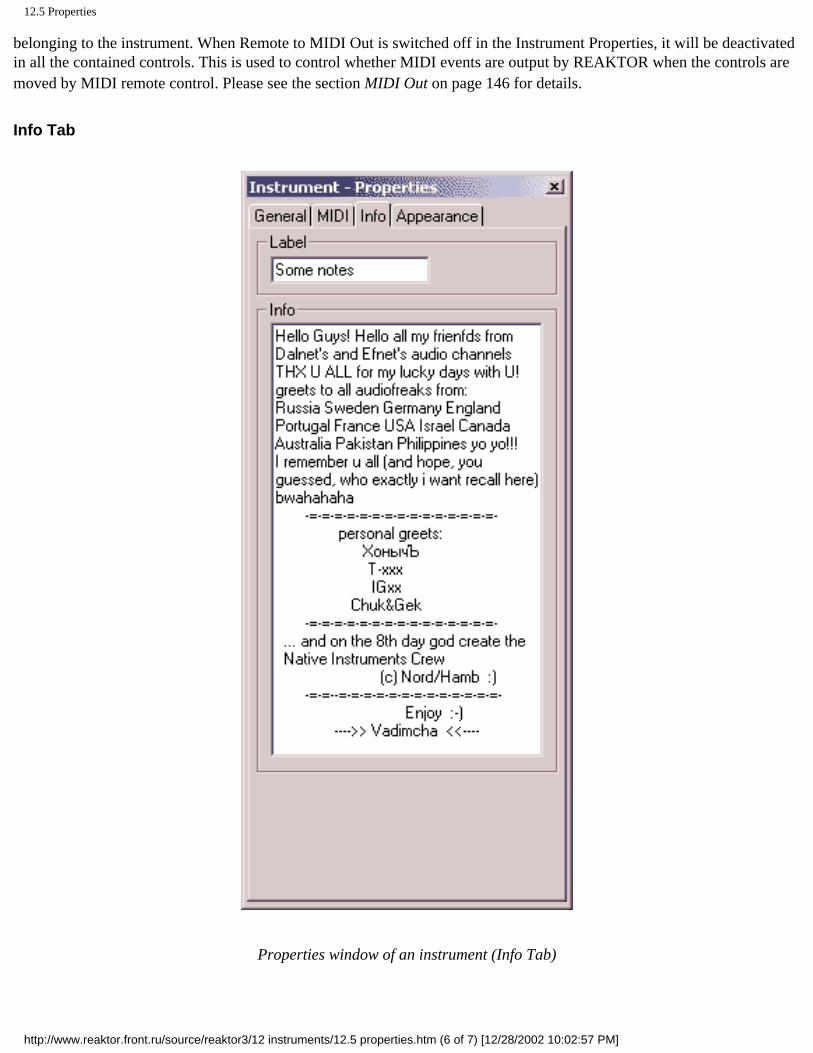
12.5 Properties
belonging to the instrument. When Remote to MIDI Out is switched off in the Instrument Properties, it will be deactivated in all the contained controls. This is used to control whether MIDI events are output by REAKTOR when the controls are moved by MIDI remote control. Please see the section MIDI Out on page 146 for details.
Info Tab
Properties window of an instrument (Info Tab)
http://www.reaktor.front.ru/source/reaktor3/12 instruments/12.5 properties.htm (6 of 7) [12/28/2002 10:02:57 PM]

12.5 Properties
• Enter important information about your instrument into the Text field in the Info tab. This text is displayed whenever you hold your mouse above an empty space of an instrument panel or the instrument symbol in the structure window (when the Info-Button in the Toolbar is pressed).
• In the section Structure View Bitmap you can load your own bitmaps for the instrument symbol in the structure windows. Use Unload to reset the instrument icon to the standard bitmap.
http://www.reaktor.front.ru/source/reaktor3/12 instruments/12.5 properties.htm (7 of 7) [12/28/2002 10:02:57 PM]
13 Macros
Click here to show toolbars of the Web Online Help System: show toolbars
13 Macros
● 13.1 What is a Macro? ● 13.2 Creating Macros ● 13.3 Ports ● 13.4 Context Menu
http://www.reaktor.front.ru/source/reaktor3/13 macros/13 macros.htm [12/28/2002 10:02:58 PM]

13.1 What is a Macro?
Click here to show toolbars of the Web Online Help System: show toolbars
13.1 What is a Macro?
Macros have an internal structure just like instruments, but unlike instruments they do not have their own management of MIDI data, no separate panel and no snapshots. Macros have a gray label and can be recognized by an icon representing a structure with 3 modules.
The main application for macros is the encapsulation of functional blocks to obtain a hierarchical and clearer layout of complex structures. Extensive structures should always be realized using macros. Macros are also a convenient way to build re-usable components.
Example for the integration of a macro into a structure
http://www.reaktor.front.ru/source/reaktor3/13 macros/13.1 what is a macro.htm [12/28/2002 10:03:00 PM]

13.2 Creating Macros
Click here to show toolbars of the Web Online Help System: show toolbars
13.2 Creating Macros
Macros are added into a structure (often an instrument) by loading them from the library which comes with the REAKTOR software. In the folder Macros of the library there are numerous ready-made utility and specialized components. If you want to start developing a new macro you first need to load an empty one from the library (Macros\New\).
When inserting a macro you are in effect creating a local copy of the macro from the file. This means that changes made later to the file do not touch the macro once it has been inserted. Likewise, the file does not change when editing the macro in REAKTOR. If you want to update the file you must write the macro back to it using Save As....
http://www.reaktor.front.ru/source/reaktor3/13 macros/13.2 creating macros.htm [12/28/2002 10:03:02 PM]

13.3 Ports
Click here to show toolbars of the Web Online Help System: show toolbars
13.3 Ports
There is no fixed arrangement of ports for macros, rather the type and number of ports in a macro is determined by the user by the insertion of Terminals in the structure. A terminal in the macro's structure appears as a port on the macro's module representation at the next higher level (Parent) in the hierarchy. In this way wires connected to the macro's inputs feed it signals which are processed in its internal structure and then passed back to the parent structure through the macro's output ports. For details see section Terminals on page 133.
http://www.reaktor.front.ru/source/reaktor3/13 macros/13.3 ports.htm [12/28/2002 10:03:03 PM]

13.4 Context Menu
Click here to show toolbars of the Web Online Help System: show toolbars
13.4 Context Menu
The context menu of a macro contains eight entries:
• Mute disables the macro.
• Mono switches the macro to monophonic operation by switching all the modules inside to mono. You should always use this function unless the module has to work polyphonically because in mono mode there is significantly less load on the CPU .
• Cut removes the macro from its current position. It is copied to the clipboard from where it can be inserted at another place, even in another window, using the Paste command.
• Copy marks the macro for copying. A copy of the macro is stored in the clipboard from where it can be inserted at another place, even in another window, using the Paste command.
• Delete removes the macro and everything it contains.
• Save As... allows saving the macro. The file location as well as the filename can be specified. Macro files are given the filename extension .mdl.
• Structure opens the macro's structure window to display its internal wiring. See the section Structures on page 125 for details about creating and edition structures.
• Properties opens a window with information about the macro.
http://www.reaktor.front.ru/source/reaktor3/13 macros/13.4 context menu.htm [12/28/2002 10:03:05 PM]

14 Structures
Click here to show toolbars of the Web Online Help System: show toolbars
14 Structures
● 14.1 What is a Structure? ● 14.2 Modules ● 14.3 Sources ● 14.4 Switches ● 14.5 Terminals ● 14.6 Wires ● 14.7 Event Signals ● 14.8 Context Menu
http://www.reaktor.front.ru/source/reaktor3/14 structures/14 structures.htm [12/28/2002 10:03:07 PM]

14.1 What is a Structure?
Click here to show toolbars of the Web Online Help System: show toolbars
14.1 What is a Structure?
REAKTOR is based on an open concept that allows the design and realization of any imaginable sound generator. In many respects it is similar to the classic modular synthesizer systems. That's why the most important basic building block you deal with in REAKTOR is the module.
A library of elementary modules is built into REAKTOR. These provide the basic building blocks for MIDI and audio signal processing. Complex signal processing structures can be created by connecting modules which carry out relatively simple tasks.
A window, where modules are placed and interconnected, is called a Structure.
A structure window
When building structures in REAKTOR, keeping to certain hierarchical principles is highly recommended, even if REAKTOR does not force these on you but basically gives you complete freedom. For example, it is possible to make a structure using just elementary modules at the ensemble level, i.e. the highest level in REAKTOR. But there are at least two good reasons to avoid this method of construction: first, you very quickly loose sight of where you are going, and second, the number of elements in a structure is limited (to 100 in the current version).
When creating complex devices, it is important to maintain a clear layout. The following recommendations will help maintain an appropriately clean design.
• At the ensemble level, only work with instruments if possible, not with elementary modules. Also, elements like mixers which you use to process signals from several instruments before audio output should be constructed as separate
http://www.reaktor.front.ru/source/reaktor3/14 structures/14.1 what is a structure.htm (1 of 2) [12/28/2002 10:03:09 PM]

14.1 What is a Structure?
instruments, or at least as macros.
• During the construction of instruments group as many functional blocks as possible in the form of macros. This has the advantage that identical elements such as oscillators or envelopes, which are often used more than once in the construction of synthesizers, need only be constructed once and can then be copied easily. Also, your structures will become very clear so that you will find it easier to track down any problems.
http://www.reaktor.front.ru/source/reaktor3/14 structures/14.1 what is a structure.htm (2 of 2) [12/28/2002 10:03:09 PM]

14.2 Modules
Click here to show toolbars of the Web Online Help System: show toolbars
14.2 Modules
A module is the smallest hierarchical unit in REAKTOR. It is displayed as a graphical object. Each module is marked with a label and an icon (e.g. showing its waveform for oscillators).
The Pulse FM oscillator module
Creating
To create a new module use the context menu of the structure window. The sub-menu Modules creates an elementary module from REAKTOR'S built in library. A popup menu with several levels appears:
First you select the functional group (e.g. Filter) and then choose the actual module (e.g. Multi/LP 4-Pole). Detailed information about all of REAKTOR'S modules can be found in the volume called Module Reference.
The new module will be placed at the point in the window where you opened the context menu (with a right mouse-click (Windows) or ctrl + mouse-click (MacOS)), but then you can move it around like any other REAKTOR object.
http://www.reaktor.front.ru/source/reaktor3/14 structures/14.2 modules.htm (1 of 4) [12/28/2002 10:03:12 PM]
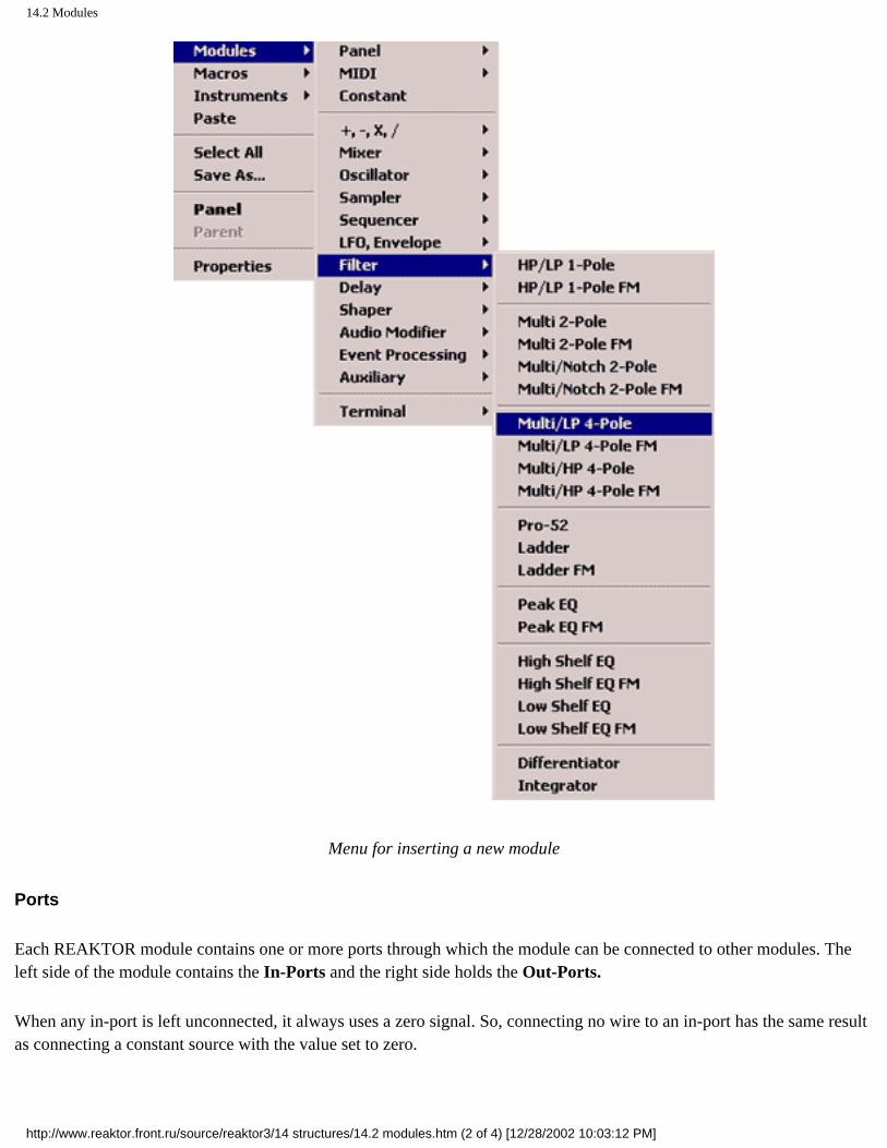
14.2 Modules
Menu for inserting a new module
Ports
Each REAKTOR module contains one or more ports through which the module can be connected to other modules. The left side of the module contains the In-Ports and the right side holds the Out-Ports.
When any in-port is left unconnected, it always uses a zero signal. So, connecting no wire to an in-port has the same result as connecting a constant source with the value set to zero.
http://www.reaktor.front.ru/source/reaktor3/14 structures/14.2 modules.htm (2 of 4) [12/28/2002 10:03:12 PM]
14.2 Modules
REAKTOR distinguishes between two kinds of information that can be understood or sent by a port, audio and events:
• Audio signals are comparable to sound signals and control voltages in the analog world. The processing of such a signal constitutes a permanent load on the CPU . Ports for audio signals are labeled with black characters. When wiring audio ports, note that an audio input can never process more than one signal. If more than one audio signal is to be fed to an audio input, they must first be mixed using an audio adder or a mixer module. If a connection is made to an audio in-port that already has a wire attached, the first wire will be deleted as the second one is connected.
• Event signals are control messages for changing a value. Typical sources for events are MIDI inputs and panel faders. Event processing allows complex manipulation of control messages without continuous calculations and thereby reduces the load on the CPU. Ports for event signals are labeled with dark red characters and marked with a small dark red dot. An event input can be fed from several event outputs, in which case the events from the different sources will be merged into one stream. Gate signals are a special case of Event signals. An event with a non-zero value turns on the gate. When it is followed with a zero-valued event, the gate is turned off again.
Each port has a context menu with the following entries:
• Create Control automatically creates a suitable panel controller for the port. (see the section Panel Controls on page 140 for details about working with controllers on the panel).
• Wire/Unwire creates a connection from this port to another port.
• Mute temporarily deactivates the port, i.e. sets its value to zero. Muted ports are marked with a small red cross.
• Properties opens a dialog window with information about the port.
Mono
A module can operate either in monophonic, i.e. single voice, mode or in polyphonic mode where processing is carried out for several voices in parallel. The number of voices of a polyphonic module is determined by the instrument to which the module belongs. Polyphonic modules can be identified by the yellow color of the status lamp at the bottom left corner of the module. Monophonic modules have an orange status lamp. For most modules the operating mode can be changed using the entry Mono in the context menu or the Mono switch in the Module Properties. Unless a module is really needed in poly mode it should definitely be used in mono mode. The CPU load is proportional to the number of voices used.
Mute
Modules can be deactivated by selecting Mute in the context menu or in the Properties dialog of the module. Muted modules are recognized by a red cross over the status lamp.
A muted module no longer causes any computational load. If a module is not needed temporarily it should be deactivated (if it is never used it should be deleted).
Modules are automatically deactivated if their outputs are not connected, or are only connected to other deactivated
http://www.reaktor.front.ru/source/reaktor3/14 structures/14.2 modules.htm (3 of 4) [12/28/2002 10:03:12 PM]

14.2 Modules
modules. The status lamp of deactivated modules is unlit.
This feature is especially useful when using switches, because alternative branches of signal processing can be selected but only one causes CPU load. It works like this: Only one of the inputs of a switch is active at any one time - the switch position determines which input. The signals of all the modules connected to inactive inputs are therefore not needed. REAKTOR turns them off, so that they do not cause any unnecessary load on the CPU.
Cut, Copy & Paste
The context menu entry Cut removes the module from its current position. It is copied to the clipboard, where it can be inserted at another place, even in another window, using the Paste command.
Copy marks the module for copying. A copy of the module is stored in the clipboard from where it can be inserted at another place, even in another window, using the Paste command.
You can also use the key combinations Ctrl (mac) + X (Cut), Ctrl (mac) + C (Copy) and Ctrl mac) + V (Paste). When using the keyboard shortcut Ctrl (mac) + V for pasting, you can specify a point in the structure by clicking there with the left mouse button first.
Delete
The context menu entry Delete removes the module and everything it contains. You can also delete a selected module(s) with the Del key on the computer keyboard.
Properties
A dialog window with information about the macro can be opened with the context menu entry Properties. For detailed information about all modules please see the Module Reference.
http://www.reaktor.front.ru/source/reaktor3/14 structures/14.2 modules.htm (4 of 4) [12/28/2002 10:03:12 PM]

14.3 Sources
Click here to show toolbars of the Web Online Help System: show toolbars
14.3 Sources
What are Sources?
In REAKTOR, Source is the name given to a module which outputs a control signal. There are three different kinds of sources:
• Control-Sources have a representation on the panel. The panel element is used to set the value of the control signal.
• MIDI-Sources convert MIDI data to control signals.
• Constant-Sources have a fixed value.
Control Sources
The module types Fader, Knob and Button are the control sources. There are two ways to insert them into a structure:
• Choose the desired module from the context menu of the structure window (Modules=>Panel=>Fader/ Knob / Button).
• In the context menu of a module in-port select Create Control. A control source is created and connected to the input. Type, label and settings of the control source are already configured to suit the input. In many cases you can save a lot of time by using this feature to add control sources.
Control sources and their respective panel elements can be controlled via MIDI in various ways. Please see the section MIDI Control on page 144 for details about this topic.
MIDI Sources
MIDI source modules are used for controlling the audio signal processing with MIDI events. For each type of MIDI event there exists a particular kind of source module. The output signal of such a source corresponds to the values transmitted by the particular MIDI events. The OnVelocity source for example outputs a control signal
MIDI sources are created through the context menu of the structure window by choosing the desired kind of MIDI data in Modules=>MIDI
Range of Values
http://www.reaktor.front.ru/source/reaktor3/14 structures/14.3 sources.htm (1 of 3) [12/28/2002 10:03:14 PM]
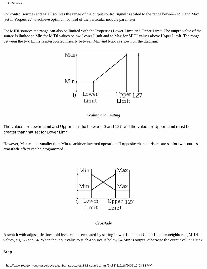
14.3 Sources
For control sources and MIDI sources the range of the output control signal is scaled to the range between Min and Max (set in Properties) to achieve optimum control of the particular module parameter.
For MIDI sources the range can also be limited with the Properties Lower Limit and Upper Limit. The output value of the source is limited to Min for MIDI values below Lower Limit and to Max for MIDI values above Upper Limit. The range between the two limits is interpolated linearly between Min and Max as shown on the diagram:
Scaling and limiting
The values for Lower Limit and Upper Limit lie between 0 and 127 and the value for Upper Limit must be greater than that set for Lower Limit.
However, Max can be smaller than Min to achieve inverted operation. If opposite characteristics are set for two sources, a crossfade effect can be programmed.
Crossfade
A switch with adjustable threshold level can be emulated by setting Lower Limit and Upper Limit to neighboring MIDI values, e.g. 63 and 64. When the input value to such a source is below 64 Min is output, otherwise the output value is Max.
Step
http://www.reaktor.front.ru/source/reaktor3/14 structures/14.3 sources.htm (2 of 3) [12/28/2002 10:03:14 PM]

14.3 Sources
The range of values in source modules normally has a resolution of 128 steps. In many modules (particularly Fader and Knob) the parameter Step can be used to reduce the resolution to fewer than 128 steps. You enter the step size by which the output value is to change, beginning at Min. For example you can set a pitch parameter to select only octaves by giving it a Step value of 12.
Constant Sources
Constant sources are what you need to supply the input to a module with a fixed value. The desired value is set in the Properties of the Constant module with Constant Value.
A constant source is created by selecting Modules=>Constant in the context menu of the structure window.
http://www.reaktor.front.ru/source/reaktor3/14 structures/14.3 sources.htm (3 of 3) [12/28/2002 10:03:14 PM]

14.4 Switches
Click here to show toolbars of the Web Online Help System: show toolbars
14.4 Switches
Switches are not sources because they do not generate any control signals. They are controls, however, because (like other control sources) they are represented on the panel by a control element.
Several modules can be connected to the inputs of a switch and the position of the switch then determines which signal is passed to the output of the switch. An exception are switches of type "1" which only toggle between activating and deactivating the signal path. They are simply on/off switches for signals. Details on all kinds of switches can be found in the Module Reference.
The use of switches in a structure can also play a significant part in reducing the load on the processor. This is because modules or parts of the structure that are not connected to REAKTOR'S audio outputs (or to an input of a Tapedeck module) do not add anything to the audio signal and are therefore automatically switched off. In this state they do not cause any CPU load. For example, you may use a switch to select one of several oscillators. Only the oscillator whose signal is being output will be active, while all the other oscillators are automatically deactivated.
http://www.reaktor.front.ru/source/reaktor3/14 structures/14.4 switches.htm [12/28/2002 10:03:16 PM]

14.5 Terminals
Click here to show toolbars of the Web Online Help System: show toolbars
14.5 Terminals
Terminals are very inconspicuous but immensely important modules in REAKTOR structures. They are like the sockets on hardware instruments. Each input or output terminal within a structure appears at the next higher level - i.e. in the instrument or macro - as a port through which connections to other instruments, macros and modules can be made.
According to the different kinds of module ports, four different types of terminal ports are available: Audio in. Audio Out, Event in and Event Out. The normal rules for wiring apply (see section Rules for Wiring on page 135), where, for instance, an Audio in terminal can only be connected to an audio out-port of a module.
Terminals are created using the context menu of the structure window by selecting the desired kind of terminal under Modules=>Terminal .... The Label of a terminals is initially just in or Out, but if you have several Ins or Outs you should give them meaningful names (like L and R in this picture) to prevent any possible confusion. You should also provide terminals with a description (info) in the Properties. The label appears as the port label in the representation at the next higher level (Parent), and the description is shown as the hint for the port when the mouse pointer rests on it (provided Show Hints is enabled).
http://www.reaktor.front.ru/source/reaktor3/14 structures/14.5 terminals.htm (1 of 2) [12/28/2002 10:03:18 PM]

14.5 Terminals
Instrument with ports and its structure with terminals
http://www.reaktor.front.ru/source/reaktor3/14 structures/14.5 terminals.htm (2 of 2) [12/28/2002 10:03:18 PM]

14.6 Wires
Click here to show toolbars of the Web Online Help System: show toolbars
14.6 Wires
The connection between the ports of two modules, shown as a line, is called a wire. Wires transport signals between the modules.
Connecting a wire
Creating
There are two ways to make a new wire: Click on one of the two ports to be connected with the left mouse button, move the mouse pointer to the other port and click this one also. A visible connection (that's the wire) appears between the ports and the effect on the sound resulting from the change to the structure can be heard immediately. The wiring operation is aborted if you click the left mouse button somewhere other than on a valid port.
• Click on the entry Wire/Unwire in the context menu of the port. Then move the mouse pointer to the other port and click the left mouse button on it. Again, the wiring operation is aborted if you click the left mouse button somewhere other than on a valid port, like an empty part of the window.
Deleting
There are two ways to delete a wire:
• Do the same as you would to create a new wire. When you repeat the wiring operation for an existing wire this removes the connection. (That's why the entry in the context menu is called Wire/Unwire)
• Select the wire you want to delete by clicking on it with the left mouse button or by opening a frame that covers both its ends (selected wires are displayed colored). To delete it simply press the Del key on your computer keyboard.
http://www.reaktor.front.ru/source/reaktor3/14 structures/14.6 wires.htm (1 of 3) [12/28/2002 10:03:21 PM]

14.6 Wires
Rules for Wiring
When wiring modules together there are some general rules to be
observed:
• A wire can only connect an out-port to an in-port.
• An out-port can be connected to up to 16 in-ports.
• When no wire is connected to an in-port, it receives a zero signal.
In addition, the following special rules apply:
• An event in-port cannot process audio signals . If an event in-port is to be fed from an audio out-port, the signal must first be converted with an A to E module (see Module Reference).
• An event in-port can be fed from up to 16 event out-ports. If there is more than one connection, the event signals are merged so that it is always the last received event that determines the value.
• An audio in-port can only be fed from a single out-port.
• An event out-port can be connected to audio in-ports as well as event in-ports.
• When connecting a mono output to a poly input all voices receive the same signal. For pitch signals this means the voices in effect play in unison.
• Apoly output cannot be connected to a mono input (a red cross appears on the in-port). A Voice Combiner module must be used for converting poly to mono.
Hints
While the mouse pointer rests on a wire (and if Show Hints is switched on), the value of the signal on the wire is shown as a hint.
For event signals, the value of the last event is shown (if the events come faster than the rate at which the display updates, some intermediate values may be missed).
For audio signals, a rough indication of minimum and maximum values, i.e. the range of the signal, is given. (Short peaks in the signal may be missed and thus do not show up in the display). If the range of the signal is changeable, you may need to move the mouse pointer away from the wire to close the hint. and then point on the wire once more to start measuring minimum and maximum values again.
http://www.reaktor.front.ru/source/reaktor3/14 structures/14.6 wires.htm (2 of 3) [12/28/2002 10:03:21 PM]

14.6 Wires
For polyphonic signals, the values for all voices are displayed, one line of values for each voice. At the left, the MIDI note numbers which are playing on the respective voices are shown. If a voice is not playing any note, Note: Off is displayed along with the value of the signal on the wire. Voices with note off are always shown below the voices with note on.
http://www.reaktor.front.ru/source/reaktor3/14 structures/14.6 wires.htm (3 of 3) [12/28/2002 10:03:21 PM]

14.7 Event Signals
Click here to show toolbars of the Web Online Help System: show toolbars
14.7 Event Signals
An event has two properties: the time instance at which it occurs, and the value it carries, which is the new value when used as an audio signal.
Every event signal is also an audio signal, so it has a value for every sample. The difference is that this value is constant, until an event comes along to change the value. This means that every event output can also be used like an audio output, but the signal will be stepped, not smooth.
Some Modules (A to E, for example) only evaluate an audio signal connected to its input at the control rate.
Most Modules which operate on Events (Event Add, Timer or Compare, for example) work at the exact instance that an event arrives. The event timing is limited only by the audio sample rate, i.e. it's as accurate as anything. Other event modules (A to E or LFO, for example) operate only at the lower timing resolution determined by the Control Rate, say 200 times a second.
Order of Event-Processing
Most event processing modules, in response to an input event, generate an output event immediately. That is, an event travels through the chain of event modules to the end (possibly fanning out if there are several paths) before the next event travels the chain.
The method is "depth before breadth: an event propagates as deep as it can along one track before another wire fanning out from the same port is considered.
If one event is to go down more than one branch, and you need to have the branches executed in a defined order, you should use the Event Order module to fan out to the different paths.
Another important module in this context is the Event Value module. A complex event processing structure can be connected to its Val input, but it will only pass on this value as an event when a triggering event arrives at the in input. You can look at this as a Sample&Hold circuit triggered by an event. You can use the Event Order module to generate this triggering event and make sure that it occurs after other event processing has completed.
When different source modules produce events at the same moment in time, for example when they are initialised as the structure is turned on, they actually send events in the order in which the source modules were originally inserted into the structure. To have one module initialised after the others, simply cut it and paste it back into the structure.
http://www.reaktor.front.ru/source/reaktor3/14 structures/14.7 event signals.htm [12/28/2002 10:03:23 PM]

14.8 Context Menu
Click here to show toolbars of the Web Online Help System: show toolbars
14.8 Context Menu
The context menu of the structure window has nine entries:
• Modules is for inserting elementary modules into the structure.
• Macros is for inserting macros from the library into the structure.
• instruments is for inserting instruments from the library into the structure.
• Paste inserts a previously cut or copied object into the structure at the point where the context menu was opened. When using the keyboard shortcut Ctrl + V for pasting, you can specify a point in the structure by clicking there with the left mouse button first.
• Select All selects all the objects in the structure.
• Save As... is for saving the structure to a file with a new name. Depending on the type of structure (instrument or macro) the correct filename extension will be appended.
• Panel opens the panel window which belongs to the structure. For macros, the panel command opens the panel window of the instrument or ensemble of which the macro is a part.
• Parent opens the structure of the hierarchical level above. For example, if you are in the structure of a macro which is part of an instrument, the parent command will open the instrument's structure.
• Properties opens a dialog window with settings and a description of the instrument or macro to which the current structure belongs. See the section Properties on page 115 for details about the Properties of instruments.
http://www.reaktor.front.ru/source/reaktor3/14 structures/14.8 context menu.htm [12/28/2002 10:03:26 PM]

15 Panel Editing
Click here to show toolbars of the Web Online Help System: show toolbars
15 Panel Editing
● 15.1 What is a Panel? ● 15.2 What are Controls? ● 15.3 Panel Controls ● 15.4 Editing the Panels
http://www.reaktor.front.ru/source/reaktor3/15 panel editing/15 panel editing.htm [12/28/2002 10:03:28 PM]

15.1 What is a Panel?
Click here to show toolbars of the Web Online Help System: show toolbars
15.1 What is a Panel?
A Panel is the user interface of an instrument. It corresponds to the front panel of a hardware synthesizer or effects unit, where the knobs and switches for operating the device are located. REAKTOR panels are displayed in their own type of window, the Panel window.
http://www.reaktor.front.ru/source/reaktor3/15 panel editing/15.1 what is a panel.htm [12/28/2002 10:03:31 PM]

15.2 What are Controls?
Click here to show toolbars of the Web Online Help System: show toolbars
15.2 What are Controls?
All the control sources and switches that are part of a structure also appear in the panel window in the form of controls. Depending on the type of source module, they are represented as faders, knobs, buttons or switches. Each is used for setting the output signal of the corresponding source module or (in the case of switches) for changing the signal flow.
On the left a panel with faders, on the right the structure with the corresponding control source modules
http://www.reaktor.front.ru/source/reaktor3/15 panel editing/15.2 what are controls.htm [12/28/2002 10:03:33 PM]

15.3 Panel Controls
Click here to show toolbars of the Web Online Help System: show toolbars
15.3 Panel Controls
Faders
Faders are linear sliding controllers in the panel, whose position determines the control value of the corresponding source module The range of output values of the fader is set with the values Mm and Max in the Module Properties The resolution can be set with the property Step (when Step is zero there are 128 steps)
In addition to moving a Fader with the mouse, it can also be remote controlled with MIDI (see section MIDI Control on page 144)
A fader can be changed to a knob by selecting Knob under Panel Appearance in the Properties With Show Value and Show Label the display fields for value and label in the panel representation can be enabled or disabled The fader can also be displayed at half size by selecting Small Design
All these settings can be made in the Properties dialog window of the fader control in the Panel window or in the Properties dialog window of the corresponding control source module m the Structure window
Knob
Knobs work Just like faders, only that they appear as rotary controllers in the panel
A knob can be changed to a fader by selecting Fader under Panel Appearance in the Properties With Show Value and Show Label the display fields for value and label in the panel representation can be enabled or disabled The knob can also be displayed at half size by selecting Small Design
Button
Buttons are switching controllers in the panel, whose position determines the control value of the corresponding source module The output values of the button in the states On and Off are set with On Value and Off Value in the Module Properties
Besides operating the Button with the mouse, it can also be remote controlled with MIDI (see section MIDI Control on page 144)
With Show Value and Show Label the display fields for value and label in the panel representation can be enabled or disabled The button can also be displayed at half size by selecting Small Design
http://www.reaktor.front.ru/source/reaktor3/15 panel editing/15.3 panel controls.htm (1 of 2) [12/28/2002 10:03:35 PM]

15.3 Panel Controls
All these settings can be made in the Properties of the button control in the Panel window or in the Properties of the corresponding control source module in the Structure window
Switch
Switches are used to activate and deactivate different signal paths by choosing one of the switch inputs to connect to the output There are separate types of switch modules for audio and event signals Both kinds of switches are available with varying number of inputs
The Labels of the switch module's in-ports in the structure window are also used as labels for the buttons that make up the switch in the panel window You should definitely give them meaningful names, otherwise you may quickly forget what it was that the particular switch turns on or off
With Show Label the display field for the label in the panel representation can be enabled or disabled
http://www.reaktor.front.ru/source/reaktor3/15 panel editing/15.3 panel controls.htm (2 of 2) [12/28/2002 10:03:35 PM]
15.4 Editing the Panels
Click here to show toolbars of the Web Online Help System: show toolbars
15.4 Editing the Panels
Just like the modules in a structure, the controls in the panel can be edited with Cut, Copy, Paste and Delete However, with all these operations, remember that they always have a direct effect on the respective structure For example, if you delete a control from the panel you are also deleting the corresponding source module in the structure, because the two are inseparable We that you carry out these operations only in the structure so you can keep control of the outcome
Moving controls in the panel, on the other hand, has no effect on the structure Simply click the left mouse button on the label of the control you want to move and drag it with held mouse button to the desired position Once all controls have been arranged it is best to activate the
Lock function. When Lock is enabled it is no longer possible to move and panel elements. The Lock function is set using the context menu of the panel window or by clicking on the button with the padlock icon in the Instrument Toolbar.
http://www.reaktor.front.ru/source/reaktor3/15 panel editing/15.4 editing the panels.htm [12/28/2002 10:03:37 PM]

16 Panel Operation
Click here to show toolbars of the Web Online Help System: show toolbars
16 Panel Operation
● 16.1 Mouse Control ● 16.2 Key Control ● 16.3 MIDI Control ● 16.4 MIDI Out ● 16.5 Snapshots
http://www.reaktor.front.ru/source/reaktor3/16 panel operation/16 panel operation.htm [12/28/2002 10:03:39 PM]

16.1 Mouse Control
Click here to show toolbars of the Web Online Help System: show toolbars
16.1 Mouse Control
Fader
To change the value, click the left mouse button on the fader and, keeping the button pressed, move the mouse up or down until the desired position is reached.
Knob
To change the value, click the left mouse button on the knob and, keeping the button pressed, move the mouse up or down until the desired position is reached.
Button
There is a choice of three operating modes for buttons. Each mode can be chosen in the Properties dialog window:
• Trigger: Pressing the button generates an event with the On Value. Releasing the button does not generate an event.
• Gate: Pressing the button generates an event with the On Value. Releasing the button generates an event with the Off Value.
• Toggle: The button has two stable states. Pressing it once switches it on; an event with the On Value is generated. Pressing it again switches it off; an event with the Off Value is generated.
When connecting the button to an audio in-port, Trigger mode behaves the same as Gate mode, i.e. the signal returns to the Off Value when the button is released.
Switch
Pressing one of the buttons on a switch selects the corresponding input of the switch and connects it to the output. Only one of the buttons of a switch can be active at a time, and therefore only one of the inputs can be enabled at any one time.
http://www.reaktor.front.ru/source/reaktor3/16 panel operation/16.1 mouse control.htm [12/28/2002 10:03:42 PM]

16.2 Key Control
Click here to show toolbars of the Web Online Help System: show toolbars
16.2 Key Control
The currently selected fader, knob or switch can also be controlled with keys on the computer keyboard.
The position of Faders and Knobs changes like this:
• Key: Value Change:
• UP-key +Step
• Down-key -Step
• PgUp + 10 x Step
• PgDn -10 x Step
A Switch changes the active input on pressing the keys UP/DOWN.
The control element to which the keys apply can be selected with the keys RIGHT/LEFT.
http://www.reaktor.front.ru/source/reaktor3/16 panel operation/16.2 key control.htm [12/28/2002 10:03:44 PM]
16.3 MIDI Control
Click here to show toolbars of the Web Online Help System: show toolbars
16.3 MIDI Control
MIDI Data Types
If Remote is activated in the Properties dialog window of a control element it can be remote controlled via MIDI. One of the following kinds of MIDI data can be used:
• MIDI Controller messages: The number of the MIDI controller assigned to the panel element is set with Controller/Note No in the Properties or using the MIDI Learn function.
• MIDI Poly-Aftertouch messages: The MIDI note number of the message is set with Controller/Note No in the Properties or using the MIDI Learn function.
Faders and Knobs move their position to follow the received MIDI data.
When operating Buttons by remote control, the Button turns on when the received MIDI Controller or Poly Aftertouch message has a value greater than 63. With Buttons it is also possible to use Note On/Off messages to control the button.
When operating Switches by remote control with MIDI Controller or Poly Aftertouch messages, the Switch changes to a position corresponding to the received value. For this the range of possible values (0 to 127) is divided into regions of equal size according to the number of inputs on the switch (e.g. with 4 inputs: 0 ... 31, 32 ... 63, 64 ... 95, 96 ... 127). The value 0 always selects the input at the bottom, 127 selects the input at the top.
MIDI Learn
The MIDI Learn function is switched on with the button on the Instrument Toolbar. It is identified by an icon representing a MIDI socket and the letter L. It is a very efficient tool for assigning MIDI messages to control elements on the panel.
Select the control element which is to be remote controlled, click on the Learn button and send the MIDI data that you want to use for controlling (by moving the hardware wheel, knob, fader, pedal or other controller). To MIDI-fy other controls just repeat this operation.
The REAKTOR software automatically detects whether the controller data comes from a standard MIDI controller or from an incremental controller like the 4Control made by NATIVE INSTRUMENTS. The panel element's incremental mode switch is set accordingly. In the rare case that the MIDI Learn function choses the wrong mode, simply repeat the operation or set the correct mode in the Properties of the panel element manually.
http://www.reaktor.front.ru/source/reaktor3/16 panel operation/16.3 midi control.htm (1 of 2) [12/28/2002 10:03:46 PM]

16.3 MIDI Control
Incremental
You need to activate this entry in the Properties of controls or MIDI source modules if you want to use the optional 4Control MIDI Unit by NATIVE INSTRUMENTS to set the value. The 4Control sends relative position values for forward or backward movement of the knobs (63 = 1 step back, 65 = 1 step forward). In incremental mode this values get translated to absolute values (0 ... 127). For details about using REAKTOR with the 4Control please see the section 4Control MIDI Unit on page 182.
Soft Takeover
When a fader or knob is being operated by MIDI remote, it normally Jumps straight to the received controller value Such a Jump can be quite noticeable in the sound, depending on the controlled parameter (e. g. amplifier level) and is often not desirable Such Jumps can be avoided by selecting Soft Takeover in the Properties of the relevant controls The control will only move when the value received via MIDI reaches or goes past the current position
http://www.reaktor.front.ru/source/reaktor3/16 panel operation/16.3 midi control.htm (2 of 2) [12/28/2002 10:03:46 PM]

16.4 MIDI Out
Click here to show toolbars of the Web Online Help System: show toolbars
16.4 MIDI Out
When Panel to MIDI-Out is activated in the Properties of a panel element, any movements on the panel will be translated to MIDI data which are output by REAKTOR The same kind of MIDI events as are received by the controller (Remote) are used to output the movements
A second option Remote to MIDI-Out determines whether the events that are received over MIDI (Remote) for the particular control element are also sent to the output Take care, though, that when connecting to a sequencer which sends MIDI data to REAKTOR and at the same time receives MIDI from it In this case, a feedback loop may result
http://www.reaktor.front.ru/source/reaktor3/16 panel operation/16.4 midi out.htm [12/28/2002 10:03:48 PM]

16.5 Snapshots
Click here to show toolbars of the Web Online Help System: show toolbars
16.5 Snapshots
What are Snapshots?
Snapshots are REAKTOR'S sound settings and correspond to the memories of conventional synthesizers, called "programs" or "patches" A snapshot records the current setting of all the instrument's panel control elements and MIDI controllers By recalling a snapshot all the settings are restored to the saved state Each instrument can store 128 snapshots
Recalling
Snapshots are recalled using the selection list in the Instrument Toolbar of the main window This presumes that the window of the wanted instrument is active You open the list of the snapshots by clicking the left mouse button on the box marked u, then you can choose a snapshot to recall Just click on the box and it becomes active The snapshot that was last recalled is always shown in the Toolbar You can also recall snapshots by moving around the list with the cursor keys UP/DOWN
Snapshots can also be recalled using MIDI Program Change messages Make sure that Snapshot Recall by MIDI is activated in the instrument's Properties, otherwise MIDI program change messages have no effect The number preceding the snapshot label, which indicates the snapshot's position in memory, is also the number of the MIDI Program Change that recalls the snapshot
It is also possible to link snapshot in different layers of the hierarchy When recalling a snapshot in the ensemble, for example, the instruments in the ensemble will also change snapshot if they have Snapshot Recall by Parent activated in their respective Properties The snapshot that the instrument reverts to is the same number that it was set to at the time that the ensemble's snapshot was generated
Storing
To store a snapshot, left-click with the mouse on the Store button (which has an icon representing a camera) in the Instrument Toolbar The Snapshots dialog window opens up
With NO you can assign a memory position (and MIDI Program Change number) to the snapshot With Label you give the snapshot a name Clicking on Store then saves the snapshot and closes the dialog window
You can also replace the snapshot shown under Select (by default the current snapshot) with the current control settings by clicking on Overwrite. The snapshot is stored with the new settings but under the old name at the old location.
http://www.reaktor.front.ru/source/reaktor3/16 panel operation/16.5 snapshots.htm (1 of 2) [12/28/2002 10:03:51 PM]

16.5 Snapshots
The dialog window used to store, delete, rename and copy snapshots.
Deleting
To delete a snapshot, left-click with the mouse on the Store button in the Instrument Toolbar. The Snapshots dialog window opens up.
Now choose the snapshot to be deleted in the Select list and click on Delete to remove it from the list.
Copying and Renaming
To copy or rename a snapshot you first have to recall it using the list in the Instrument Toolbar. Next open the Snapshots dialog window by pressing the button with the camera icon. Then choose the current snapshot in the Select list to copy its number and label to the fields at the bottom.
To rename the snapshot, give it a new name under Label and press Store to overwrite the old position with the new name.
To copy the snapshot, enter a new number under No and press Store to copy it to that location with its old name.
Snap Isolate
When recalling a snapshot, the controls normally jump to the position stored in the snapshot. If for some reason you want to prevent this for certain panel elements or MIDI controllers, you can do so by activating Snap isolate in the Properties dialog window. The relevant controls are then immune to snapshot recall.
http://www.reaktor.front.ru/source/reaktor3/16 panel operation/16.5 snapshots.htm (2 of 2) [12/28/2002 10:03:51 PM]

17 Sampling and Re-Synthesis
Click here to show toolbars of the Web Online Help System: show toolbars
17 Sampling and Re-Synthesis
Since REAKTOR is a modular system, it does not require a fixed structure for organizing samples The "Transformator" Tour (section The "Tiansformatoi" Tour on page 44) uses examples from the library to show you how to create instruments as powerful as you like. Just by interconnecting modules in complex ways However, it also demonstrates how simple instruments can be constructed using the simplest of means
● 17.1 Sample Management ● 17.2 Sample-Maps ● 17.3 Sampler Properties Dialog ● 17.4 Akai Import
http://www.reaktor.front.ru/source/reaktor3/17 sampling and re-synthesis/17 sampling and re-synthesis.htm [12/28/2002 10:03:53 PM]
17.1 Sample Management
Click here to show toolbars of the Web Online Help System: show toolbars
17.1 Sample Management
Sound Files and Samples
REAKTOR takes its samples, i. e. the audio material to be processed in the Sampler modules, from WAV or AIFF formatted mono or stereo sound files, which can be at any sample rate Besides the sound waveforms that are contained in the sound file, REAKTOR also reads any loop and keyboard allocation information (if available) from the sound file
Before REAKTOR can use a sound file it needs to be loaded into the computer's RAM Regardless of the data format (bit depth) of the audio material in the sound file REAKTOR uses 32-bit format for the internal representation of the sample This is done for reasons of efficiency One minute of stereo sound in CD quality uses 20 MB RAM If virtual RAM is being used (the default in Windows, but not in MacOS), then a great deal more main memory can be allocated than is actually available For this reason error messages are not displayed during the loading of large sound files even when the free RAM is already exhausted
Instead you will get an error message later REAKTOR will inform you that the CPU is overloaded and processing will stop This error message is displayed because the software cannot access the sample data on the hard drive fast enough (after first having tried to access it in RAM and not having found it there) Frequently the message is preceded by an unintentional granular sound effect caused by the more or less regular interruptions of the audio data stream This situation, particularly undesirable during live performances, can only be avoided through the addition of more main memory Under Windows, if latency is not an issue, the susceptibility of the system to such problems can be reduced by use of large buffer settings (Play Ahead) (See section Latency on page 16) Under MacOS, virtual memory should be turned off, also for reasons of MIDI timing (See section Latency on page 16)
Multiple Use of Identical Samples
If one particular sample is used by several sampler modules in an ensemble, all the modules will access the same representation of the sound file that is stored in RAM This means you can load the same sample in as many sampler modules as you like without increasing the demand on RAM by any appreciable amount The number of voices used in a sampler module is irrelevant as far as memory requirements are concerned
REAKTOR identifies a sample using the path of the sound file from which the sample was loaded The path comprises the directory in which the sound file is located and the sound file's name When a sound file is loaded, REAKTOR searches through the list of samples that are already loaded, looking for a sample that has the same path and name If this sample is already present, it will simply be "reused"
Missing Samples
REAKTOR saves only the paths of the samples contained in a macro / instrument / ensemble If the sound files were
http://www.reaktor.front.ru/source/reaktor3/17 sampling and re-synthesis/17.1 sample management.htm (1 of 2) [12/28/2002 10:03:56 PM]

17.1 Sample Management
deleted, renamed or moved after the macro / instrument / ensemble was saved, it is likely that the instruments cannot be entirely recreated
In this situation you will get an error message after having opened the macro / instrument / ensemble The "missing" samples are labeled in the Properties dialog window as Missing Using the Replace button, the File-Open dialog window is activated This function allows you to localize or replace missing sound files
Sample-Backup in the Module
The loss of samples can be avoided if the Backup Sound with Module option is activated, which can be accessed via the sampler module's Properties dialog window. Sampler modules using this option will save a copy of the sample file with the module file. In most cases the increase in the file size of macro / instrument / ensemble files will be considerable, but your work can be reconstructed regardless of the circumstances.
Whenever a module containing a Sample-backup is loaded it will attempt to find the original sound file first. The Backup-files are only used if the original files cannot be located. These "restored" samples are labeled in the Properties dialog window of the relevant sample modules as Restored.
Sample-Analysis
Some modules (Sample Resynth, Sample Pitch Former, Beatloop) perform real-time re-synthesis. For this purpose, after loading, the sample will be analyzed. This process takes approximately as long as the duration of the sample. To avoid repeating analysis REAKTOR tries to save the analysis data with the sound file. This of course is only possible if the sound file is not write-protected. Also keep in mind that sound files from CD-ROMs should be copied to hard disk. If a sound file has been changed it is possible to re-analyze it.
Sample-Editors
REAKTOR does not have its own sample editor, since there are already many sample editors available on the market. In the preferences menu, the edit button can be set to launch your preferred sample editor (System Preferences Directories: Sample-Editor Application). It is also possible to edit the sound files saved using the sample-backup option.
Naturally sound files changed in the sample editor have to be saved before they can be re-loaded into REAKTOR. Use Reload in the Properties dialog window and in the context menu of the sample module.
Note: Keep in mind that some sample editors will ignore loop information present in sound files. In this case the loop regions will be lost.
http://www.reaktor.front.ru/source/reaktor3/17 sampling and re-synthesis/17.1 sample management.htm (2 of 2) [12/28/2002 10:03:56 PM]

17.2 Sample-Maps
Click here to show toolbars of the Web Online Help System: show toolbars
17.2 Sample-Maps
One of the ways of using sample maps is to better simulate acoustic instruments, usually this can be achieved by using multiple samples over a keyboard range. Stretching a sample over fewer keys will improve the naturalness of an acoustic sound. Another use of sample-maps is to trigger multiple samples with one key. Following are explanations for both uses:
Multi-Sampling
The repetitive nature of samples makes it difficult to simulate acoustic instruments. With REAKTOR it is possible to vary the sample each time it is triggered. Usually when a sample is transposed over multiple keys, the further it is transposed from the root key of the original sample the less natural it sounds. This change occurs because the spectral aspects of transposed samples do not change according to the natural changes occurring in acoustic instruments. Samplers try to overcome this limitation by using multi-sampling techniques, when each sample is only transposed a small amount from its root key.
Assuming a sample-map contains multiple samples of the original sound at least two parameters have to be set to control each sample in the map.
• The Root Key sets pitch of the untrensposed sample.
• The Left Split sets the starting point of the key zone. The end of the zone ("Right Split") does not have to be set unless wanted or imposed by the Left Split of the next sample.
The optimum result is achieved when the Root Key is kept in the middle of the Split zone and the transposition is kept to a minimum.
Every sampler module has a P(itch) input, which is used to select a sample from the map and to control the tuning of the sample. Usually this input is connected to a Note Pitch module, which sends the current MIDI note. When a sample is triggered in multi-sample mode, the value received at the P-input selects the appropriate sample and tuning.
The sample module also has a Sel(ect) input. If connected it overrides the sample selection of the P input, which then only sets the tuning. This can result in interesting sound variations.
Sample maps in REAKTOR can also be used to trigger multiple samples with only one key. This is a technique used to further mirror an instrument's dynamics. Velocity is used to achieve this via MIDI. Usually an instrument is sampled playing the same note with different dynamics. Then the dynamically different samples can be triggered using different velocities, resulting in a more expressive representation of the original sound. TRANSFORMATOR Tour (section The "Transformator" Tour on page 44) contains appropriate examples.
http://www.reaktor.front.ru/source/reaktor3/17 sampling and re-synthesis/17.2 sample-maps.htm (1 of 2) [12/28/2002 10:03:58 PM]

17.2 Sample-Maps
Drum-Maps
As in Multi-Sampling, the "Drum-Map" uses the Root Key and Left Split to determine the position on the samples in the map. Sometimes in drum sounds the Root Key of the original sample is not used or gets overly transposed. With Drum-Maps, it is possible to use any area of the key range - therefore not having the actual Root Key in the range.
As described above the Sel-input is used to override the sample selection of the P-input, which then only sets the tuning. The Sel-input can be used to achieve interesting sound variations. For example by connecting the output of a Gate module to the Sel input, the velocity information is then used to select samples from the map. This way it is possible to trigger many different samples using only one key's velocity information.
Saving Maps
You can save a Map to disk, separate from the Instrument or Ensemble that uses it. Under Windows it will be stored with the filename extension .map. The map file can contain all the sample date that is used by the map, or it can be just a small file with references to the sample files.
The loss of samples can be avoided if the Backup Sound with Module option is activated, which can be accessed via the sampler module's p
http://www.reaktor.front.ru/source/reaktor3/17 sampling and re-synthesis/17.2 sample-maps.htm (2 of 2) [12/28/2002 10:03:58 PM]

17.3 Sampler Properties Dialog
Click here to show toolbars of the Web Online Help System: show toolbars
17.3 Sampler Properties Dialog
The sampler and re-sampler modules in REAKTOR use the Properties dialog window to organize sample-maps and to set the module's parameters. The easiest way to open the Properties dialog window is by double-clicking the module or its icon in the Toolbar. The Properties dialog window varies very little between modules. For example the Sampler Loop looks like this:
http://www.reaktor.front.ru/source/reaktor3/17 sampl... and re-synthesis/17.3 sampler properties dialog.htm (1 of 4) [12/28/2002 10:04:01 PM]

17.3 Sampler Properties Dialog
Sampler Loop Module Properties dialog window The Properties dialog window is split into three areas:
The General field in the top part of the dialog window is used to set general module parameters. All REAKTOR modules have this field in their Properties dialog window.
The Sample Map field including the Module and Quality fields below it are used to set the parameters for the whole module, independent of the individual samples. Use the Done button to close the dialog window.
The Selected Sample field including the Direction and Loop fields below it are used to set sample specific parameters. These settings relate to the selected sample shown in bold in the Sample map field and only affect this module. The Apply to all Samples in Map button copies the settings from the Direction and Loop fields and applies them to all samples in the sample map.
The Sample Map Field
The Sample Map field contains sample maps, which can be selected from the list by clicking with the mouse or using the up and down keys on the computer's keyboard. This list contains the names of sound files and its location. Every entry is preceded by the left Split-point, which is represented as text (CO..G10 etc.) and also in MIDI note numbers (0..127).
The Sample Map field contains the following options:
• Load map files
• Add sound files to a map
• Sort the map
• Save the map file (.map)
When a sound file is added to a map, the sample's root key information sets the Root Key and the Left Split parameters. Should the sample not contain any root key information, a value of 60 (C3) will be used, if this value is unavailable the sample will be placed at the next available note number.
When saving a map it is possible to use the Sample Backup option. If used, this option saves samples with the map. Whenever a sound map containing a Sample-backup is loaded it will attempt to find the original sound file first. By saving the sound files with the sound map you assure that all the sound files are included within the sound map. However, the original sound files remain in their original location, therefore resulting in duplicates of the sound files. It is also possible to transfer sound maps between modules.
http://www.reaktor.front.ru/source/reaktor3/17 sampl... and re-synthesis/17.3 sampler properties dialog.htm (2 of 4) [12/28/2002 10:04:01 PM]

17.3 Sampler Properties Dialog
A single sample can be used to create a sample map. The Properties dialog window of a module does not necessarily have to be opened to load samples / maps. This task can also be achieved with the import Sound option in the context menu.
The Selected Sample Field
To the right of the Sample Map field is the Selected Sample field, which displays the parameters of the selected sample. The parameters can be changed using the scrollbar or the up and down keys. Which parameters are used depends on the module type and the map mode. All sample parameters are saved with the maps.
The Selected Sample field also contains buttons to:
• Replace the selected sample,
• Delete the selected sample from a map,
• Edit to open the selected sample in a sample editor,
• Reload the selected sample.
The Module field
Here a maximum of three parameters can be set:
• No Stereo stops stereo playback (Only the left channel is used). Activation reduces the processor load.
• Backup Sound activates the Backup Sound with Module option (see the section Saving Maps on page 154).
• Oscil. Mode places the module into oscillator mode.
Samplers in oscillator mode assume that the samples used contain waveforms or WaveSets. A waveform is a representation of a single vibration. Through repeated playback it is possible to recreate periodic vibration. The module then becomes a digital oscillator. Sampler modules in oscillator mode interpret the values at the P input in the same way as oscillators in REAKTOR - as MIDI note numbers - and produce periodical vibrations at the corresponding pitch.
In oscillator mode the Sampler and Sampler FM modules interpret the entire sample as one vibration. For example to produce a sound at 440 Hz, the entire sample is played 440 times per second, independent of the duration of the sample.
In waveform mode Sampler Loop interprets the loop length as vibrations. The loop length is read from the sound file, but can be changed at the LL input of the module (see the Module Reference). Therefore a sample can contain numerous waveforms, also known as WaveSets. Assuming a waveform contains 100 cycles, then 100 such waveforms fit into a sample the size of 10,000 cycles. The first waveform covers cycles 0-99, the second 100-199 etc. If the loop length sets the vibration of a waveform, the position of the loop logically sets the choice of waveforms from the WaveSet. Sampler Loop uses the LS input to control the loop start point. In waveform mode the values at this input are quantized, so that glitch free
http://www.reaktor.front.ru/source/reaktor3/17 sampl... and re-synthesis/17.3 sampler properties dialog.htm (3 of 4) [12/28/2002 10:04:01 PM]

17.3 Sampler Properties Dialog
playback between waveforms is achieved. The position in a WaveSet can be easily controlled by velocity, etc. Obviously such WaveSet samples need to be either created or generated from a sample. The library contains many WaveSet examples. Sampler Loop integrates WaveSet Synthesis with REAKTOR'S existing synthesis capabilities. In this way, WaveSet Synthesis is now available for the first time in combination with FM synthesis.
The Quality Field
Sets the playback quality of the sample in three options (Poor, Good and Excellent). Higher quality increases the processor load.
The term "quality" refers to the absence of noise. Naturally, noise may actually improve the musical "quality" of a sample.
The Direction Field
Sets the playback direction (Forward or Backward) of the sample.
The Loop Field
A maximum of three loop parameters can be set here:
• On / Off activates the sample-loop
• Alternating Loop activates alternating loop playback. The sample will be played alternatively forwards and backwards within the loop.
• Loop in Release keeps the loop playback in the release phase (only available for modules with a G input).
http://www.reaktor.front.ru/source/reaktor3/17 sampl... and re-synthesis/17.3 sampler properties dialog.htm (4 of 4) [12/28/2002 10:04:01 PM]

17.4 Akai Import
Click here to show toolbars of the Web Online Help System: show toolbars
17.4 Akai Import
Akai import is possible from the sample modules context menus and their properties. Select the entry Akai Import to open an import window which shows the content of an Akai formatted CD-ROM inserted into your CD drive. If the content of the CD doesn't appear in the browser window press the Reload CD button.
The browser window displays all partitions, volumes, programs and samples, lets you explore the content of the Akai-CD and allows converting selected Akai programs and samples to Reaktor Map files (file extension *.map). Converted files will be stored into the folder you have specified as imported Files path in the Reaktor preferences.
When loading or converting to a Map file, Reaktor will keep the following sample information:
• Sample data
• Loop points
• Root key
• Pan
The following information will not be kept at this time:
• Filter settings
• Envelope settings
• Velocity splits
• Gain
It is also possible to load Akai samples and programs directly into a sample module by pressing the button Load as map. In this case you can save the samples as Map file using the Save button of the Sample properties window or save them with the ensemble by ticking the checkbox Backup Sound.
Ticking the checkbox Mute audio engine while loading causes a faster import, but Reaktor will stop any audio output while loading.
http://www.reaktor.front.ru/source/reaktor3/17 sampling and re-synthesis/17.4 akai import.htm [12/28/2002 10:04:03 PM]

18 Table Modules
Click here to show toolbars of the Web Online Help System: show toolbars
18 Table Modules
The new Audio Table and Event Table modules bring another dimension to Reaktor and will change the way instruments are designed. The Table modules allow handling events and audio data in a very flexible way. There is a terrific amount of new possibilities available in Reaktor using the Table modules. It is now possible to design Oscillators, LFOs or Waveshapers by drawing your own waveforms with the mouse. Or you can crossfade between wavetables and create envelopes with curve shapes drawn by hand or with countless breakpoints. The Event Table can be used as a sequencer for outputting gate and pitch values or for controlling any parameter in a Reaktor ensemble. These are just some basic ideas for applications and you can probably imagine that there will be a lot more which can be done with these two modules.
● 18.1 Properties ● 18.2 Context Menu ● 18.3 Advanced Operation
http://www.reaktor.front.ru/source/reaktor3/18 table modules/18 table modules.htm [12/28/2002 10:04:06 PM]

18.1 Properties
Click here to show toolbars of the Web Online Help System: show toolbars
18.1 Properties
The Event Table and Audio Table modules have an extensive Properties dialog which is identical for both kinds of module. Some general properties which are available in many other modules are not covered again here.
Function Tab
Interpolation
• None
No interpolation happens when reading between cell values. Only the integer part of values arriving at the RX and RY inputs are used. The result is a stepped output signal even when the input position changes smoothly. The display looks stepped like a bar chart in the 1D-modes.
• X
Interpolation between values is only used on the X-axis. The full precision of fractional values at the RX input is used to compute smooth transitions when reading between table cells.
. Y
Interpolation between values is only used on the Y-axis. The full precision of fractional values at the RY input is used to compute smooth transitions when reading between table cells. • XY
Interpolation between values is used in both the X and Y-axis. The full precision of fractional values at the RX and RY inputs is used to compute smooth transitions when reading between table cells.
No Interpolation
http://www.reaktor.front.ru/source/reaktor3/18 table modules/18.1 properties.htm (1 of 9) [12/28/2002 10:04:09 PM]

18.1 Properties
X-Interpolation
When X interpolation is active, the table diagram shows the interpolation by displaying a smooth curve. Interpolation is never displayed in 2D-mode.
Clip/Wrap XY
• Clip
When reading beyond the end of the table you get the value of the last cell. Reading before the start of the table you get the value of the first cell.
• Wrap
When reading beyond the end or start of the table it continues at the other end of the table as if it was arranged as a circular loop.
Backup Data with Module
Activate this option to save the data in the table within the ensemble, instrument or macro file.
Appearance Tab
Graph Format
This dropdown list selects how the values are displayed in the Table module's panel graph. You can choose between four modes:
- Pixel
Values are drawn with a horizontal line. If you set no interpolation for the X axis the lines look like small faders.
http://www.reaktor.front.ru/source/reaktor3/18 table modules/18.1 properties.htm (2 of 9) [12/28/2002 10:04:09 PM]

18.1 Properties
Pixel
• Line
Values are drawn with a horizontal line and vertical lines are also drawn to connect the values.
Line
• Bar
Values are drawn with a horizontal line, vertical lines are drawn to connect and the area underneath is filled with color.
Bar
• 2D
This mode is for viewing more than one row at a time. This is what you need to see all of a 2-dimensional table (Y-Size > 1). The value of each cell is displayed as the color of the corresponding rectangle. The rows are numbered from top to bottom, the columns always from left to right.
http://www.reaktor.front.ru/source/reaktor3/18 table modules/18.1 properties.htm (3 of 9) [12/28/2002 10:04:09 PM]

18.1 Properties
2D
Visible
• Picture
The graphic area is displayed on the panel when this option is enabled. It is used for viewing and editing the data.
• Value
The status bar at the top of the Table graph is visible when this option is selected. It shows information relating to the mouse position in the graph, such as the X and Y position and the value in the table at the position. The units of the displayed values depend on the selected units in the Properties under the Table tab.
• Horizontal Scrollbar
Tick this option to see a scrollbar under the table graph.
• Vertical Scrollbar
Tick this option to see a scrollbar to the right side of the table graph.
X View Parameters
• Auto Fit
When this option is ticked all cells in the X direction are always displayed in the graph. The number of displayed cells is the same as the X Size in the Table tab.
• Alignment
When Auto Fit is off this slider controls how smaller regions of the data are selected. When the slider is in the left position the cell selected with the XO input appears at the left edge of the display. With the slider centered the selected cell appears in the middle. When the slider is in the right position the last cell visible at the right edge of the display is the one before XO.
http://www.reaktor.front.ru/source/reaktor3/18 table modules/18.1 properties.htm (4 of 9) [12/28/2002 10:04:09 PM]

18.1 Properties
Y View Parameters
• Auto Fit
When this option is ticked and 2D mode is selected, all cells in the Y direction are always displayed in the graph. The number of displayed cells is the same as the Y Size in the Table tab. In display modes other than 2D, Auto Fit has not effect.
• Alignment
When Auto Fit is off this slider controls how smaller regions of the data are selected. When the slider is in the left position the cell selected with the YO input appears at the top edge of the display. With the slider centered the selected cell appears in the middle. When the slider is in the right position the last cell visible at the bottom edge of the display is the one before YO.
Value View Parameters
• Auto Fit
When this option is ticked the display's value range in Pixel, Line and Bar mode is the same as the range set with Min and Max on the Table tab. In 2D mode Auto Fit has no effect.
Table Tab
File
The data in the table can be read from or stored to a file with the Load and Save buttons. The Audio Table and Event Table modules can read the following file formats:
• Table Files (*.ntf)
• Audio Samples (*.wav or *.aif)
• Plain Text (*.txt) containing numbers separated by spaces
(Text files are treated as one row of data, so Y-Size is always 1.)
The name of a loaded file will be displayed in the File Name field.
It is possible to use a text editor for creating a Table file. Just enter values for the X axis in a row with spaces between the values. Save the file with the file extension *.txt. It is not possible to create values for the Y-axis using a text file, the values are only for Y=0.
http://www.reaktor.front.ru/source/reaktor3/18 table modules/18.1 properties.htm (5 of 9) [12/28/2002 10:04:09 PM]

18.1 Properties
You can save the data from a table in a file for reusing it in other Table modules. If the same file is loaded into more than one Table module in the same ensemble, the data in this file will be shared between these modules. Modifying the table content in one module affects all other modules. If all modules display the content of the same table cells, any modification of the values is visible in realtime in the panel graphs of all table modules.
The Clients field shows the number of Table modules in the ensemble which share the same Table file.
Size
With these two value fields you can define the size of the table storage. The first field is for the number of cells on the X-axis (the width of the rows), the second for the number of cells on the Y-axis (height of the columns). Changes to the numbers of cells will not become valid until pressing the Apply button.
Note: If you reduce the number of cells, and the cells being removed contain data, then this data will be deleted together with the removed cells.
Value
Min, Max and Step work just like with Knobs and Faders.
The Default value is used to initialize cells when creating or enlarging a table or when cutting a selection from it. The Default value is also important in the display because it appears as a distinct color (normally black). Default is commonly set to 0.
Display Units
When editing the table in Draw mode, the current value is displayed in the graph's status bar in a format according to the Display Units setting.
• Numeric
Standard format for numbers in any range.
• MIDI Note
The value is rounded to the nearest integer and displayed as the equivalent MIDI Note number. For example, 60 is C3 and 58 is A#2.
• % (percent)
The range 0...1 is displayed as 0...100%. For example, 0.5 becomes 50% and 2 becames 200%.
http://www.reaktor.front.ru/source/reaktor3/18 table modules/18.1 properties.htm (6 of 9) [12/28/2002 10:04:09 PM]

18.1 Properties
X Units
Sets the units which are used to measure the horizontal cell position in the table. The following units are available:
• index
This is the default unit. The cells are numbered with integer values
(0,l,2...n). . [0...1]
The first cell has the position 0, the last the position 1. The position
of the cells in between are computed by their relative location in the
table as a fractional value between 0 and 1.
• milliseconds
The position of a cell will be computed as time in milliseconds (ms), depending on the sample rate entered in the Samples/Sec field below. This unit is especially interesting in the Audio Table module for moving inside an audio sample which was recorded in real time.
• Tempo Ticks
The position of a cell will be computed in ticks of a tempo clock. This option is especially useful in the Audio Table module with a rhythmic piece of audio loaded of which you know the BPM (Beats per Minute) tempo. The Ticks/Beat field defines how many ticks make up a beat (usually 24).
When X Units is set to milliseconds you can adjust the sample rate of the data:
Samples/Sec
How many cells correspond to one second of time. When loading a Wav or Aiff file its sample rate automatically appears here.
When X Units is set to Tempo Ticks you can also adjust the following
values:
• Samples/Tick
How many cells in a subdivision of a beat.
http://www.reaktor.front.ru/source/reaktor3/18 table modules/18.1 properties.htm (7 of 9) [12/28/2002 10:04:09 PM]
18.1 Properties
• BPM
Tempo in Beats per Minute.
• Ticks/Beat
The subdivision of a beat. For Reaktor's Master Clock this is 24.
• Number of Beats
The length of the data measured in beats (usually 4 or 8 for a
smoothly looped audio beat).
When changing one of these values, the others are automatically recomputed to match the length of the data and sample rate.
Y Units
Sets the units which are used to measure the vertical cell position in the table. The following units are available:
• index
This is the default unit. The rows are numbered with integer values
(0,l,2...n). . [0...1]
The first row has the position 0, the last the position 1. The position
of the rows inbetween are computed by their relative location in the
table as a fractional value between 0 and 1.
Grid Tab
The settings are the same for X, Y and Value Grid:
• Enabled
When this box is ticked vertical lines (X Grid) or horizontal lines (Y Grid in 2D display mode or Value Grid in the Pixel, Line or Bar display mode) will be displayed in the panel graph.
http://www.reaktor.front.ru/source/reaktor3/18 table modules/18.1 properties.htm (8 of 9) [12/28/2002 10:04:09 PM]
18.1 Properties
• Grid Step
The value entered here relates to units set for X and Y on the Table tab It sets the spacing of the grid If you want to set the basic resolution of the grid to one unit enter 1 here Enter 2 to have every second unit as a grid step, or 0 5 for two grid steps per unit
• Size 1 Size 4
There are four different sizes available for the grid lines 1 is the finest and 4 is the thickest line size The number you enter in these boxes defines how often a line with a certain thickness is drawn (number of Grid Steps per line) Enter 1 for a line at every Grid Step, or 2 for a line at every other Grid Step, for example Enter 0 if you do not want to use a size at all
http://www.reaktor.front.ru/source/reaktor3/18 table modules/18.1 properties.htm (9 of 9) [12/28/2002 10:04:09 PM]

18.2 Context Menu
Click here to show toolbars of the Web Online Help System: show toolbars
18.2 Context Menu
When you click the right mouse button (Mac mac+mouse button) on a table graph, a special context menu for editing in the graph becomes visible Once you get more familiar with the editing options we recommend using keyboard shortcuts which are available for most of the operations since you can navigate and operate much faster like this Keep in mind that the shortcuts only apply to the data in the graphs when the Lock button in the Toolbar is pressed
Show
• Show All
Zooms out fully so that the whole table is visible in the graph
• Show Selection
Zooms the display so that the current selection completely fills the display
• Next Y (Page Down)
In Pixel, Line and Bar mode the next higher row of table cells is displayed In 2D mode the graph is scrolled vertically one row up
• Previous Y (Page Up)
In Pixel, Line and Bar mode the next lower row of table cells is displayed In 2D mode the graph is scrolled vertically one row down
• Pixel Mode
• Line Mode
• Bar Mode
• 2D Mode
It is possible to change the display mode of the table graph directly with the context menu without overwriting the
http://www.reaktor.front.ru/source/reaktor3/18 table modules/18.2 context menu.htm (1 of 4) [12/28/2002 10:04:11 PM]

18.2 Context Menu
Properties settings Read more about the four graph display modes above in the description of the Appearance tab in the Properties
Select
. Select All (Ctrl+A)
Selects all currently visible data
• Select X All
Selects all currently visible data in the selected rows
• Select YAH
Selects all currently visible data in the selected columns
• Snap Selection to Grid
With this option enabled, the edges of any selection are always adjusts to lie on the Grid, which may be much coarser than the cell size, depending on the settings in the Properties on the Grid tab When the Grid's smallest line size is not visible because the display is zoomed out to display a lot of data, then the selection snaps to the smallest Grid size that is still visible
Process
• Mirror X
Swaps the data between left and right using a vertical symmetry axis in the middle of the selection
• Mirror Y
In 2D mode, swaps the data between top and bottom using a horizontal symmetry axis in the middle of the selection
• Rotate
Allows numerical entry for rotating the selection by the given amount Cells which are moved out of the selected area on one size reappear on the other side in a circular motion
• Add Value
Allows numerical entry for adding or substractmg from the values of selected data
http://www.reaktor.front.ru/source/reaktor3/18 table modules/18.2 context menu.htm (2 of 4) [12/28/2002 10:04:11 PM]

18.2 Context Menu
• Scale Value...
Allows numerical entry for scaling the values of selected data. (1=100%, 0.5=50%, 2=200% ...)
• Quantize Value to Step Size
When this option is selected, values drawn with the mouse snap to the step size set in the table module Properties. This is the normal behaviour. Unselect this option to draw at a finer resolution despite the set step size.
• Set 2D Draw Value...
You can enter a value which is used when you draw values in 2D mode. You can also pick a value from the View by pressing Ctrl+mouse button in draw mode.
• Draw Mode
This mode allows you to enter values with the mouse. You can draw curves or modify single values by moving the mouse up and down. In 2D-mode you set the value with which you draw with the menu option Set 2D Draw Value... or you pick an existing value with Ctrl-mouse click on a cell in the graph.
• Select Mode
In Select mode, instead of drawing with the mouse to change the values, you use the mouse to select a region for modifying later. The selected data can then be worked on with the editing functions.
You can change from Draw to Select mode and back by pressing the Tab
key.
Cut, Copy, Paste
• Copy (CTRL+C)
Copies the selected data into the copy buffer.
• Cut (CTRL+X)
Cuts the selected data and puts it in the copy buffer.
• Paste (CTRL+V)
http://www.reaktor.front.ru/source/reaktor3/18 table modules/18.2 context menu.htm (3 of 4) [12/28/2002 10:04:11 PM]

18.2 Context Menu
Pastes data from the copy buffer into the current selection.
Load Data..., Save Data
These menu options are shortcuts for the Load and Save buttons in the File section of the Table tab in the Properties. Please see page 164 for more details on Table files.
Save Data as...
Save a Table file under a new name.
Reload Data
If you have modified a table file outside Reaktor you can load the new version with this menu entry.
http://www.reaktor.front.ru/source/reaktor3/18 table modules/18.2 context menu.htm (4 of 4) [12/28/2002 10:04:11 PM]

18.3 Advanced Operation
Click here to show toolbars of the Web Online Help System: show toolbars
18.3 Advanced Operation
Draw / Select Mode
The current editing mode is displayed in a square at the top left in the status bar as a D or S to indicate Draw or Select Mode. You can toggle the mode by clicking on the square.
The Tab key also toggles the editing mode.
Rotate
By holding the Shift key and dragging with the mouse you can move all cells in the selected area left and right, or in all directions in 2D-mode. When everything is selected, you can drag around the whole graph.
Add
By holding the Ctrl key and dragging the mouse up or down you modify the value of everything in the selected area. An amount is added to or subtracted from all the values, depending on how far you drag the mouse.
Lock Mode
There is a connection between the Lock button in the Toolbar and the Table modules. When the Lock button is activated, panel operations with keyboard shortcuts like copy (Ctrl+C) and paste (CTRL+V) apply to the selected data inside the table graph instead of the module itself. So when the panel is locked you are moving the data in the module instead of moving the module's representation on the panel.
Keyboard Shortcuts
There is a list of keyboard shortcuts for the Table modules in the appendix on page 181.
http://www.reaktor.front.ru/source/reaktor3/18 table modules/18.3 advanced operation.htm [12/28/2002 10:04:13 PM]

19 Appendix
Click here to show toolbars of the Web Online Help System: show toolbars
19 Appendix
● 19.1 Troubleshooting ● 19.2 Watching the CPU Load ● 19.3 Key Commands ● 19.4 4Control MIDI Unit
http://www.reaktor.front.ru/source/reaktor3/19 appendix/19 appendix.htm [12/28/2002 10:04:15 PM]

19.1 Troubleshooting
Click here to show toolbars of the Web Online Help System: show toolbars
19.1 Troubleshooting
Before contacting our hotline, please check whether your problem is already described here.
Also please see the file Readme.txt in the REAKTOR installation. Here you may find additional advice that could not be included in this guide when it went to press.
Possible Problems
There is No Sound
Please make sure that audio processing is activated at the main switch of the Ensemble-Toolbar. If the display of the Out level meter is gray and the CPU Load Display shows Off, no audio driver port is open.
Windows: If the CPU load shows 0.0, the connection to the driver is interrupted. Please check the installation of the soundcard and its driver, as well as the settings in the Audio Settings... dialog window. If you do not find any problems reboot your system. This is the only way to reactivate a damaged driver.
Open the TestTone ensemble that comes with the REAKTOR library (in Ensembles\New). If after loading it you can hear a sine wave tone, there is no problem with audio output. If other ensembles will not play, the problem probably lies with MIDI reception. If there is no sound output with the TestTone ensemble, check if the audio output of the soundcard is correctly connected to an amplifier.
REAKTOR Does Not Respond to MIDI
First check if the MIDI lamps in the Ensemble Toolbar and in the Instrument Toolbar show any activity. If only the ensemble MIDI lamp lights up, make sure that the instrument's MIDI receive channel matches the arriving data. If the lamps stay dark (indicating that no MIDI signals are reaching REAKTOR), check whether the MIDI port that you want to use is installed in REAKTOR (System MIDI Settings: installed Ports). See section MIDI Settings... on page 97.
Finally you can investigate whether the MIDI interface is connected correctly and recognized by Windows 95/98: Close REAKTOR and start the included MIDI Monitor program (MidiMon.exe in REAKTOR'S folder Bin\). If no MIDI events are received there, a problem exists with your MIDI connection and has nothing to do with REAKTOR.
MIDI Port is Not Available
When another program is already using a particular MIDI port then REAKTOR cannot access the same port and will not
http://www.reaktor.front.ru/source/reaktor3/19 appendix/19.1 troubleshooting.htm (1 of 5) [12/28/2002 10:04:18 PM]

19.1 Troubleshooting
show it in the list of installed ports on startup. You can ensure that REAKTOR has access to the relevant interface by starting REAKTOR before any other MIDI program.
Program Terminates on Opening the MIDI Settings Dialog window
If REAKTOR stops abnormally when you open the MIDI Settings dialog window, then the cause is to be found with the MIDI drivers on your system. Uninstall all or individual drivers until you have isolated the problem.
Note that Windows 95/98 can only handle up to ten MIDI devices. Possibly, the allowed number was exceeded with the installation of REAKTOR. In this case the problem can be solved by removing some MIDI drivers.
Clicks or Crackle in the Sound
Normally, if the speed of your computer is not sufficient for computing the set number of voices at the set sample rate in real time a warning message (..Processor Overload")appears. Sometimes, especially when the CPU load limit (..Maximum processor usage in %") in Preferences is set very high, interruptions in the audio signal in the form of single or repeated clicks may occur.
Reduce the sample rate, the number of voices or the complexity of the ensemble and watch the CPU load in the Toolbar or using the System Monitor.
Undesired Audible Distortions (Clipping)
If clipping distortion occurs, it is most probably the result of too high a signal level being applied to the Audio-Out module. This is because all other modules have a much larger dynamic range due to the internal floating point data format. Clipping in the soundcard's digital to analogue converter is indicated by the Out lamp in the Toolbar turning yellow.
Reduce the signal level at the audio output. The easiest way is to connect a fader to the Lvl input of the Audio-Out module, with the range set to Min = -60 [dB] and Max - 0 [dB], and pull the fader down until the distortion stops.
Clipping occurs when the signal at the input to the Audio-Out module (with Lvl set to 0 [dB], i.e. no amplification of attenuation) exceeds the range ± 1. Please note that when playing polyphonic instruments the instantaneous levels of all the voices are added up. In this way an instrument with four voices and with a peak level of ± 0.25 per voice fully uses the available dynamic range of the audio output.
Undesired Audible Distortions (Chopping)
If the sound output is severely chopped up, it may be that you have set Play ahead in the Audio Settings dialog window at too small a value. Set Play ahead to the maximum value and see whether the distorted sound becomes smooth. Then optimize the setting as described on page 9.
Long Delay
If you find that the delay (latency) between hitting a key and hearing the resulting sound is very long, it may be that you
http://www.reaktor.front.ru/source/reaktor3/19 appendix/19.1 troubleshooting.htm (2 of 5) [12/28/2002 10:04:18 PM]

19.1 Troubleshooting
have not optimized the Play ahead setting in the Audio Settings dialog window. By default the latency is set at maximum to guarantee smooth operation with any soundcard and driver. To get good performance you must optimize the setting by hand as described on page 8.
Audio Instabilities
A sudden rise in CPU load, a loud noise or interruption in the audio signal (without program being terminated) can be due to instability in a module. The problem can be removed by briefly deactivating the appropriate module through muting and unmuting. It may be necessary to alter some control signal to make sure that the module does not immediately return to its problematic state.
Sound Disturbances During Display Activity
If you hear noises in REAKTOR'S sound when moving windows around the screen, the problem is with the graphics card. Many graphics cards try to increase their performance by occupying the system bus longer than permitted, thus locking out other bus users (such as REAKTOR and the soundcard). The result is that REAKTOR is unable to transfer its audio data to the soundcard without interruption.
Many graphics cards, fortunately, can be made to change their behavior with a command in the appropriate system file. If you have a card using the S3 chip, you should add "busthrottle=l" under [display] in sys-tem.ini, for example.
Generally, you should deactivate special mouse symbols or pointer trails in the Mouse settings in the Control Panel. You could also try reducing hardware acceleration or install a new graphics display driver, if available. In some cases all we can advise you to do, unfortunately, is to get a different graphics card.
Sound Disturbances During Disk Activity
Occasionally, during sizeable hard disk access the operating system does not leave enough CPU time for REAKTOR to function properly. Because the drivers for the hard disk run at the very highest priority they can block execution of the REAKTOR audio thread. Some CD-ROM drives cause the same kind of problem.
Similarly, interruptions in the sound can appear when other programs running in the background execute extensive hard disk operations. Under Windows, the program for index generation that is supplied as part of Microsoft Office 97 for example, works its way through all installed disks every 2 hours in default setting. You should increase its update interval or simply uninstall this program.
Periodic Audio Interruptions
Some printer drivers (e.g. HP LaserJet, Canon BubbleJet) can cause disturbance. When the printer cable is not connected or the printer is not switched on, regular bursts of noise (period about 3 seconds) may result. If you do not want to connect the printer you have to deactivate the printer driver.
In general you should consider all drivers for other hardware as possible sources of trouble, and if appropriate temporarily disable them .
http://www.reaktor.front.ru/source/reaktor3/19 appendix/19.1 troubleshooting.htm (3 of 5) [12/28/2002 10:04:18 PM]

19.1 Troubleshooting
One Instrument Does Not Produce Sound
Please check the structure to see if there are any invalid (muted) connections between polyphonic outputs and monophonic inputs or between polyphonic ports of different instruments. You identify these by the small red X which marks any muted in-ports. In addition, you can check if modules are deactivated because they are part of an unconnected branch. If there are any dark activity lamps, the problem is to be found in the wiring or muting of modules downstream of the deactivated module.
Two Ports Cannot Be Connected
Event inputs cannot process audio signals and can therefore not be connected to audio outputs. When attempting to connect two such ports, no wire appears. If you really want this connection, you must connect an A to E converter module (see the Module Reference) between the two ports.
Wrong Font Size for Labels
If the display of module labels is impaired by large lettering, choose a smaller screen font. Use the menu Start=>Settings=>Control Panel=> Display=>Appearance). When the system font is too large and the screen resolution is small, some large menus may be incompletely displayed.
The CPU Load is Too High
If the computing power of your computer is not sufficient to process the sound generation structure you have constructed, you may need to manage the available resources better. You should first get an idea how much load the various modules are causing by activating load measuring mode with System=> Measure CPU Usage
Check whether some modules can be operated in mono mode. Is it really necessary for signals to be generated for many different parallel voices or is one signal enough? Processor usage is proportional to the number of voices.
Also check whether there are any signals that are being processed as audio when event processing would be sufficient. An adder, for example, that is only connected to event modules at its inputs should be an event adder. An audio adder requires many times more processing effort.
Also examine whether it may be possible to implement the desired behavior in a different, more elegant way, that requires less processing.
Program Crashes When Using Audio Inputs.
The low latency technology employed in REAKTOR makes high demands on soundcard drivers. Many drivers, especially older ones, are not able to cope and cause system crashes or incorrect operation particularly when using audio input. Please make sure you have the very latest drivers available for your soundcard.
REAKTOR Cannot be Restarted
http://www.reaktor.front.ru/source/reaktor3/19 appendix/19.1 troubleshooting.htm (4 of 5) [12/28/2002 10:04:18 PM]

19.1 Troubleshooting
If REAKTOR has been shut down because it has performed an illegal operation, is possible that the operating system is damaged. For this reason, it occasionally may not be possible to restart REAKTOR. In this case the computer has to be shut down. Once the computer has been restarted, everything should run as usual unless there is a more fundamental problem. If in doubt always restart to return the operating system to a reliable state.
If All Else Fails
If you are unable to sort out a problem yourself, ask us for advice. You can reach our technical hotline on:
• E-Mail: [email protected]
• Tel: +49 - 30 - 28 38 86 42
• Fax: +49 - 30 - 28 38 86 43
http://www.reaktor.front.ru/source/reaktor3/19 appendix/19.1 troubleshooting.htm (5 of 5) [12/28/2002 10:04:18 PM]
19.2 Watching the CPU Load
Click here to show toolbars of the Web Online Help System: show toolbars
19.2 Watching the CPU Load
With REAKTOR'S Toolbar or with the function Measure CPU Load you can monitor the load on the CPU due to REAKTOR'S audio signal processing. It may be important, though, to know the total load on the CPU caused by all active processes. Under Windows, you use the System Monitor program (Sysmon.exe) for this. If you keep it running in the background you can keep an eye on the processor load in a little window at the edge of the screen.
The program is a standard accessory that comes with Windows 95/98. If it is not already part of your Windows installation you can find it in the folder REAKTOR\Bin or you can install it from your Windows 95/98 CD.
You can create a CPU load display in the System Monitor by opening the menu Edit=>Add item => Kernel => Processor Usage (%) The Numeric Chart display uses the least space Activate the option View Always on Top if you want the window always to be visible and not covered by other windows
Important To work correctly, the System Monitor must be started before REAKTOR If you put a shortcut to sysmon.exe into the folder Start Up of the Start menu, the program will be started automatically when Windows boots up
CPU load values in excess of 80% can be problematic User interface response becomes sluggish and interruptions in the sound can occur In this case you have to work with smaller structures, fewer voices or a reduced sample rate Other programs are best closed if they are not needed
http://www.reaktor.front.ru/source/reaktor3/19 appendix/19.2 watching the cpu load.htm [12/28/2002 10:04:20 PM]

19.3 Key Commands
Click here to show toolbars of the Web Online Help System: show toolbars
19.3 Key Commands
On the Macintosh, the • (Command) key is used instead of Ctrl
Ctrl + N New Ensemble = Open an empty ensemble New ens
Ctri+O Open an ensemble, instrument, or macro
Ctrl+S Save Ensemble = Save the current ensemble, overwriting the file of the ensemble which was loaded last
Ctrl + E Save Window As Save the macro or instrument in the selected window
Ctrl+Z Undo last edit
Ctrl+Y Redo last undo
Ctrl + X Cut selected modules or panel elements
Ctrl + C Copy selected modules or panel elements
Ctrl+V Paste modules or panel elements from the clipboard at the point specified with a left mouse-click
Ctrl + A Select All modules or panel elements in the active window
Ctrl + M Mute on/off for selected modules
0 in keypad Run Audio, toggle between on and off
Ctrl + U Measure CPU Usage = Measure contributions to CPU load
Ctri+T Store Snapshot = Store, delete, or rename a snapshot
Ctrl +1 MIDI-Learn function activate/deactivate
Ctri+L Lock panel elements in position
Alt + Return Alt + Enter Properties of the instrument or macro whose panel is shown
Ctrl + B Panel of the instrument, whose structure window is selected
Return Structure of the instrument, whose panel window is selected
Ctrl + P Parent of the macro or instrument, whose structure window is selected
Ctrl + H Show/Hide Hints toggle on/off
Del, Down (Backspace) Delete the selected modules, wires or panel elements
Esc Cancel a process, close a dialog window
Table Graph
http://www.reaktor.front.ru/source/reaktor3/19 appendix/19.3 key commands.htm (1 of 2) [12/28/2002 10:04:23 PM]

19.3 Key Commands
Key commands for the Table graphs (only available when the Lock button is pressed and the Table module selected)
Ctrl+C Copy data
Ctrl + X Cut data
Ctrl + V Paste data
Ctrl + A Select all visible data
Tab Toggle Edit Mode (Draw / Select i
Cursor Up Move Up in the view
Cursor Down Move down in the view
Cursor Left Move left in the view
Cursor Right Move right in the view
Ctrl+CursorUp Vertical zoom in
Ctrl+CursorDown Vertical zoom out
Ctrl+CursorLeft Horizontal zoom in
Ctrl+CursorRight Horizontal zoom out
Shift+CursorUp Decrease selection range (Y)
Shift+CursorDown Increase selection range (Y)
Shift+CursorLeft Decrease selection range (X)
Shift+CursorRight Increase selection range (X)
Ctrl+Shift+CursorUp Move selection up in the view
Ctrl+Shift+CursorDown Move selection down in the view
Ctrl+Shift+CursorLeft Move selection left in the view
Ctrl+Shift+CursorRight Move selection right in the view
PageUp Previous Y Position
PageDown Next Y Position
Ctrl+LeftMouseButton (In 2D/Draw mode) Picks new drawing value
Musical Note Keys
• Holding UP Shift raises all notes by two octaves (+24).
• Holding Ctrl + UP Shift lowers all notes by two octaves (-24).
http://www.reaktor.front.ru/source/reaktor3/19 appendix/19.3 key commands.htm (2 of 2) [12/28/2002 10:04:23 PM]

19.4 4Control MIDI Unit
Click here to show toolbars of the Web Online Help System: show toolbars
19.4 4Control MIDI Unit
The 4Control by NATIVE INSTRUMENTS is a hardware control unit which uniquely complements the REAKTOR. The 4Control sends MIDI events when the four rotary knobs and two buttons are operated. Using the MIDI Learn function, the control elements on REAKTOR'S panels can easily be assigned to the knobs of the 4Control. A special feature of the 4Control are the four continuous dials; dials that have no stops so that they can function from any position. With these, discrepancies between the position of software knobs on the screen and hardware knobs on the external controller unit are now a thing of the past.
To make optimal use of the continuous rotary knobs, the REAKTOR has been equipped with incremental mode, which must be enabled for every panel element which is to be operated from the 4Control (see section Incremental on page 145). When using the MIDI Learn function, the incremental mode is detected and set automatically.
http://www.reaktor.front.ru/source/reaktor3/19 appendix/19.4 4control midi unit.htm [12/28/2002 10:04:25 PM]

20 Glossary of Synthesizer Terms
Click here to show toolbars of the Web Online Help System: show toolbars
20 Glossary of Synthesizer Terms
ADC
Analog to Digital Converter. The electronic circuit used to convert audio signals from their analog representation, as used by microphones, to a digital representation, as used by the processor. An ADC is necessary to be able process audible sounds in a digital audio system, and has to perform quantization on the continuous analog signal. Most PC soundcards have an ADC for input of signals from microphone, line or CD.
ADSR
A kind of envelope that has the parameters attack, decay, sustain and release.
Aftertouch
Pressure applied to a key after it has been played. In MIDI there are two different kinds of aftertouch messages: channel artel-touch, where there is one aftertouch value for the whole keyboard, and polyphonic aftertouch, where there is a separate aftertouch value for each key that was pressed. Whenever the aftertouch value changes, a new MIDI event is generated. The aftertouch value can be between 0 and 127. Channel aftertouch is sometimes also called channel pressure, poly aftertouch is sometimes called key pressure.
http://www.reaktor.front.ru/source/reaktor3/20 glos...thesizer terms/20 glossary of synthesizer terms.htm (1 of 30) [12/28/2002 10:04:32 PM]

20 Glossary of Synthesizer Terms
Aliasing
A kind of noise or distortion that occurs when an attempt is made to make a digital representation of a signal which contains frequencies above the Nyquist limit (half the sample rate). Instead of a frequency which is x Hz above the limit, its "alias" which is at x Hz below the limit will be heard. This tends to sounds like a metallic buzz.
All Pass Filter
A filter function that lets all the frequency components in the signal spectrum pass unchanged in amplitude but delayed by varying amounts. By itself an all pass filter does not have much audible effect, but by combining the filtered audio and the original signal, then modulating the filter frequency or putting the filter in a feedback loop a number of interesting effects can be achieved.
AM
Amplitude Modulation. A procedure where the amplitude of an oscillator (the carrier) is controlled by another audio signal. In effect, the two signals are multiplied. When the modulation is periodic and of low frequency, the effect is called tremolo, when the modulation frequency is in audio range, the effect is called ring modulation.
Amplifier
A device for changing the amplitude of a signal, thus changing the volume. In digital signal processing, amplification is simply the multiplication by an amplification factor, which can be specified either directly or logarithmically in dB.
Amplitude
http://www.reaktor.front.ru/source/reaktor3/20 glos...thesizer terms/20 glossary of synthesizer terms.htm (2 of 30) [12/28/2002 10:04:32 PM]

20 Glossary of Synthesizer Terms
In a vibration or wave, the amplitude is the maximum displacement of the waveform, as measured from the midpoint. The amplitude of a sound wave determines how loud it sounds.
Analog
In analog electronics, signals are represented by voltages. These voltages can have any value, unlike digital signals which are limited to a finite set of values. But because of this analog voltages are susceptible to inaccuracies such as drift with temperature or noise emanating in the electronics. Analog synthesizers use the method called subtractive synthesis, where oscillators generate a signal with strong overtones, such as a sawtooth waveform, which are then attenuated by varying amounts using, filters.
Attack
A parameter used to set the shape of an envelope. The attack rate determines how fast the envelope signal rises from zero to the maximum level after triggering.
Attenuation
Reduction of the amplitude of a signal or signal component. The opposite of amplification.
Audio
Signal with spectral components in the range of human hearing (20 Hz -20 kHz). In digital audio systems like REAKTOR, audio signals are represented as a stream of sample values at the sample rate.
http://www.reaktor.front.ru/source/reaktor3/20 glos...thesizer terms/20 glossary of synthesizer terms.htm (3 of 30) [12/28/2002 10:04:32 PM]

20 Glossary of Synthesizer Terms
BPF
Band Pass Filter. A filter function that lets pass a band of frequency components in the signal spectrum near the cutoff frequency while suppressing high and low frequencies. The number of poles in the filter determines by how much components above and below the cutoff are attenuated.
BPM
Beats per Minute. Unit for measuring the tempo of a piece of music. 60 BPM = 1 Hz
Breakpoint
A parameter used to set the shape of an envelope. The breakpoint level determines at what point the speed of the envelope signal changes from one rate to another.
CD Quality
The digital audio data on a Compact Disc is stored as stereo PCM using 16-bit integer format at a sample rate of 44.1 kHz.
Cent
Unit of pitch to measure fine subdivisions of semitones. 100 cents are a semitone, 1200 are an octave. One cent is a
http://www.reaktor.front.ru/source/reaktor3/20 glos...thesizer terms/20 glossary of synthesizer terms.htm (4 of 30) [12/28/2002 10:04:32 PM]
20 Glossary of Synthesizer Terms
frequency ratio of 1.000578.
Channel
Most MIDI data is transmitted in channels, of which there are 16 in each MIDI connection. Channels are used to control more than one instrument over the same connection or to control multitimbral instruments. An instrument will only respond to MIDI events if it is set to receive on the same channel that data is sent on.
Chorus
An effect that is created by mixing the output of a delay (around 20 ms) with the original signal and modulating the delay time with an LFO using a sine waveform.
Clipping
Limiting a signal to a range between a maximum and a minimum value, such as occurs for example at a DAC, which has a range limited by the 16-bit PCM data format. Signal values outside the range are clipped to the maximum or minimum values. The result of clipping is a strong distortion which sounds mostly unpleasant but can also be used for effect.
Clock
A regular pulse used to control timing or tempo, for example of sequencers. If two devices are to run at the same tempo, they must be synchronized by controlling them from the same clock. MIDI clock is an event that is generated 24 times during each quarter note or beat. A clock at other rates, 16th notes for example, can be produced by frequency division of the MIDI clock.
http://www.reaktor.front.ru/source/reaktor3/20 glos...thesizer terms/20 glossary of synthesizer terms.htm (5 of 30) [12/28/2002 10:04:32 PM]

20 Glossary of Synthesizer Terms
Compressor
An audio effects device that reduces the dynamics of a signal by amplifying quiet parts and attenuating loud parts.
Controller
A controller is some kind of knob, fader, lever, wheel, switch or button that the user operates to change the value of a parameter. In MIDI there are 128 possible controllers, each identified by its assigned number. Standard controllers are 1 for modulation wheel, 2 for breath control and 7 for volume. The controller position can be set in 127 steps. Switches are controllers where a value of 64 or above is interpreted as on, 63 or less is off. Standard switches are controller number 64 for sustain pedal and 66 for hold pedal. Whenever a controller position changes, a new MIDI event is generated.
CPU
Central Processing Unit. The processor that is the heart of a computer system, capable of performing any kind of computation with the right software. See Native Processing.
Cutoff
The frequency at which a filter's transition from the pass-band to the stop-band starts. Also the frequency at which filter resonance occurs.
http://www.reaktor.front.ru/source/reaktor3/20 glos...thesizer terms/20 glossary of synthesizer terms.htm (6 of 30) [12/28/2002 10:04:32 PM]

20 Glossary of Synthesizer Terms
DAC
Digital to Analog Converter. The electronic circuit used to convert audio signals from their digital representation, as used by the processor, to an analog representation, as used by amplifiers and loudspeakers. A DAC is necessary to be able to hear a digital audio signal and is the essential part of any soundcard.
dB
Decibel. Unit for expressing the ratio of the magnitude of two signals, such as the output and input of an amplifier. One dB equals 20 times the common logarithm of the ratio. Thus, when the two magnitudes are equal the ratio is 0 dB, when one is twice as large as the reference the ratio is 6 dB, when it is 4 times as large the ratio is 12 dB and when it is half as large the ratio is -6 dB.
DC
Direct Current The average value of a signal, a constant offset in an audio signal In the spectrum of a signal, DC is the component at frequency zero
Decay
A parameter used to set the shape of an envelope The decay rate determines how fast the envelope signal drops from the maximum level to the sustain level
Delay
A device where the output is the same as the input, only delayed by a set time A delay is the basis of many popular audio
http://www.reaktor.front.ru/source/reaktor3/20 glos...thesizer terms/20 glossary of synthesizer terms.htm (7 of 30) [12/28/2002 10:04:32 PM]
20 Glossary of Synthesizer Terms
effects such as echo, chorus md flanger Also called a delay line
Detune
Operating two or more oscillators at slightly different frequencies to achieve a bigger sound With two oscillators running at frequencies 5 Hz apart, beats (variations in volume) at a frequency of 5 Hz will be heard as the waveforms go in and out of phase
Digital
In digital systems, all information is ultimately represented as numbers In digital audio, sound signals are encoded using PCM, i. e. represented by a stream of sample values at the sample rate Digital signal processing is immune to problems confronting analog electronics such as temperature drift, noise and component tolerances, but it has its own set of issues such as aliasing and quantization
Distortion
In general terms, a change in the signal that alters the basic waveform, such as filtering Particularly used to describe a non-linear operation such as clipping or saturation
DSP
Digital Signal Processing The processing of signals (generating sounds) not in analog electronic circuits but using digital microprocessors. Also Digital Signal Processor A microprocessor specially designed for signal processing tasks
http://www.reaktor.front.ru/source/reaktor3/20 glos...thesizer terms/20 glossary of synthesizer terms.htm (8 of 30) [12/28/2002 10:04:32 PM]

20 Glossary of Synthesizer Terms
Dynamics
The variation between the loudest and the quietest parts in an audio signal as measured in dB The dynamic range of human hearing, i e between a just noticeable whisper and a painful noise, is 130 dB The largest possible dynamic range of a signal in 16-bit integer format (CD quality) is 96 dB, the dynamic range of 32-bit floating point format is 1500dB
Echo
An echo effect is obtained by mixing a signal with a version of it passed through a long delay If the delay output is connected as feedback to the delay input, the echo repeats infinitely, with a decaying intensity as set by an amplifier in the feedback connection
Envelope
A time-varying signal used to control the development of a sound after it is triggered, such as by pressing a key on a keyboard Typically the envelope is set to affect the amplitude and/or filter cutoff in virtual analog sounds The shape of the envelope is pre-programmed using parameters such as attack, decay, sustain and release
Equalizer
A kind of filter used to correct imbalances in the spectrum Generally has a more subtle effect than the drastic HPF, LPF or BPF
Event
http://www.reaktor.front.ru/source/reaktor3/20 glos...thesizer terms/20 glossary of synthesizer terms.htm (9 of 30) [12/28/2002 10:04:32 PM]

20 Glossary of Synthesizer Terms
An event is a piece of information that says that something has happened, e.g. some value has changed. MIDI data is transmitted in the form of events. Typical MIDI events are note on/off, aftertouch, controller, pitchbend and program change. In REAKTOR control signals are normally transmitted in the form of events.
Exponential
A method for conveniently obtaining very large or very small numbers from a manageable (logarithmic) representation. The inverse of the exponential is the logarithm. By applying a logarithm to an exponential value the linear value is obtained.
Feedback
A way of arranging a signal processing structure such that the output signal acts on the structure's input. Feedback structures tend to take on a life of their own. If all the processing elements in the loop are linear, the result is a simple resonance, although if the signal is amplified (instead of attenuated) as it goes around the feedback loop, the resonance will increase uncontrolledly. Resonant filters, such as those in REAKTOR, contain feedback structures. If the feedback loop contains non-linear elements, the result becomes less predictable, leading to chaotic behavior, which can be very sonically interesting.
Fifth
The difference in pitch (interval) between one note and another which has 1.5 times the frequency. In standard equal tempered tuning the fifth does not have the perfect frequency ratio of 3/2, but instead 1.4983. Seven semitones make up a fifth.
Filter
http://www.reaktor.front.ru/source/reaktor3/20 glos...thesizer terms/20 glossary of synthesizer terms.htm (10 of 30) [12/28/2002 10:04:32 PM]

20 Glossary of Synthesizer Terms
A signal processing device for suppressing some components in the spectrum of a signal and sometimes boosting others. See LPF, HPF, BPF, notch filter, cutoff, transition, pole, resonance, VCF, equalizer.
Flanger
An effect that is created by mixing the output of a short delay (around 5 ms) with the original signal, feeding back to the delay input some of the output and modulating the delay time with an LFO with a sine waveform.
Floating Point Format
Representation of a number (such as a sample value) using an integer value (mantissa) and a second number (exponent) to store the position of the fractional point in the number. In this way very large as well as very small numbers can be represented most accurately (dynamic range 1500 dB). That is why in digital signal processing systems floating point representation is the best, because neither clipping nor quantization noise are an issue. The standard floating point format used by most processors uses 32 bits to store the number: 24 bits for the mantissa and 8 bits for the exponent.
FM
Frequency Modulation. A procedure where the frequency of an oscillator (the carrier) is modified by another audio signal, usually also an oscillator (the modulator). The resulting sound becomes progressively more bright and metallic as the amount of modulation is increased. This is the technique that was used in the Yamaha DX7, the first popular digital synthesizer. When the modulation is of'low frequency, the effect is called tremolo.
Frequency
The number of cycles of periodic oscillation undergone during a unit of time. Frequency is usually measured in Hz. In
http://www.reaktor.front.ru/source/reaktor3/20 glos...thesizer terms/20 glossary of synthesizer terms.htm (11 of 30) [12/28/2002 10:04:32 PM]

20 Glossary of Synthesizer Terms
musical contexts frequency is usually described in terms of pitch. Tempo is measured in BPM. Any complex signal can be viewed as the sum of many pure oscillations at various frequencies, i.e. as its spectrum.
Fundamental
The component with the lowest frequency in the spectrum of a periodic waveform. The frequency of the fundamental is the frequency at which the waveform repeats itself.
Gain
The amplification factor of an amplifier as measured in dB.
Gate
A signal generated by a keyboard. When a key is pressed the gate signal is on, when the key is released the gate signal goes off. In REAKTOR the amplitude of the gate signal is set by the velocity of the key press.
Glissando
Stepped sliding of pitch from one note to another, usually touching all the semitones in-between. See portamento.
Harmonic
http://www.reaktor.front.ru/source/reaktor3/20 glos...thesizer terms/20 glossary of synthesizer terms.htm (12 of 30) [12/28/2002 10:04:33 PM]

20 Glossary of Synthesizer Terms
An overtone of a periodic waveform.
Hold Pedal
The hold pedal works like the middle pedal on some pianos. All the notes that are playing at the moment that the pedal is pressed are held until the pedal is released. Keys that are struck while the pedal is already down are not affected. Hold is normally transmitted as MIDI controller number 66. Also sometimes called sostenuto pedal. Not to be confused with the sustain pedal.
HPF
High Pass Filter. A filter function that lets high frequency components in the signal spectrum pass while suppressing low frequencies below the cutoff. The number of poles in the filter determines by how much components below the cutoff are attenuated.
Hz
Unit for measuring frequency. Hz = hertz = cycles per second. kHz = kilohertz=1000Hz
Integer Format
Representation of a number (e.g. sample value) as one of an equally spaced set. If 8 bits are used to store the number, it can have one of 256 possible values. Using 16 bits, 65535 values are possible, e.g. -32768 to 32767 or -1 to 1 in 65535 equal steps, giving a dynamic range of 96 dB. When a value outside the fixed range is to be stored, clipping occurs. For storage of audio, 16 bits (CD quality) is adequate, but for digital signal processing a higher resolution such as 24-bit
http://www.reaktor.front.ru/source/reaktor3/20 glos...thesizer terms/20 glossary of synthesizer terms.htm (13 of 30) [12/28/2002 10:04:33 PM]

20 Glossary of Synthesizer Terms
integer or floating point is required.
Latency
The delay or time lag that occurs in a real time system between a user input and the system's response. In a keyboard synthesizer, the latency between a key press and the resulting sound should be less than about 20 ms. A slightly longer latency is irritating, much longer and the instrument cannot be played directly.
Level
The magnitude of a value, particularly an amplitude. A relative level or amplification factor (gain) is normally measured in dB.
LFO
Low Frequency Oscillator. An oscillator running at a frequency below audio range, typically 1 Hz - 10 Hz. Used for effects such as vibrato and tremolo.
Limiter
An audio effects device that prevents excessive signal levels by attenuating loud parts.
http://www.reaktor.front.ru/source/reaktor3/20 glos...thesizer terms/20 glossary of synthesizer terms.htm (14 of 30) [12/28/2002 10:04:33 PM]

20 Glossary of Synthesizer Terms
Linear
In signal processing, an operation is called linear when, applied to a pure tone, the result is again a pure tone of the same frequency, i.e. no overtones are added in the process. Non-linear operations always result in distortion. Examples of linear operations are: addition, multiplication by a constant (amplification}, filtering, delay. Examples of non-linear operations are: multiplication by a time-varying signal (ring modulation), clipping, saturation, wave-shaping, quantization.
Logarithm
A method for conveniently representing very large and very small numbers in a manageable way, for example using dB. The human perception of sound intensity is not linear (i.e. proportional to amplitude) but logarithmic (i.e. proportional to the logarithm of the amplitude). That is why it is most convenient to represent volume by a logarithmic quantity (dB). Similarly for the perception of frequency where pitch is the logarithmic representation used. The inverse of the logarithm is the exponential. By applying an exponential function to a logarithmic value the linear value is obtained.
LPF
Low Pass Filter. A. filter function that lets low frequency components in the signal spectrum pass while suppressing high frequencies above the cutoff. The number of poles in the filter determines by how much components above the cutoff are attenuated.
MIDI
Musical Instrument Digital Interface. The industry standard way to pass musical signals (other than audio) between different pieces of equipment. The hardware aspect of the interface is a special serial connection at a rate of 31.25 kBits/sec. This means that it takes less than 1 ms to transmit a MIDI event. Each MIDI connection handles 16 channels.
http://www.reaktor.front.ru/source/reaktor3/20 glos...thesizer terms/20 glossary of synthesizer terms.htm (15 of 30) [12/28/2002 10:04:33 PM]
20 Glossary of Synthesizer Terms
Modulation
Changing the characteristics of one signal using another (modulation) signal. Modulation can be applied by audio or control signals to audio or control signals. Common sources for modulation signals are LFOs, envelopes and MIDI controllers. Popular modulations are AM, FM, ring modulation, vibrato or filter sweep.
Mono
One-channel (as opposed to stereo) or one-voice (as opposed to polyphonic).
Multitimbral
A synthesizer that can generate several voices with different timbres at the same time is called multitimbral. In REAKTOR, several instruments placed in the ensemble produce multitimbral sound.
Mute
To silence or disable part of the sound generating/processing structure.
Native Processing
Performing digital signal processing using the main CPU in a computer, rather than on dedicated additional digital signal processors. Native Processing has the advantages of low cost, easily upgradable hardware and simplified software development allowing more features to be added. The fast CPUs in today's desktop computers are comparable in processing power to specialized DSPs.
http://www.reaktor.front.ru/source/reaktor3/20 glos...thesizer terms/20 glossary of synthesizer terms.htm (16 of 30) [12/28/2002 10:04:33 PM]
20 Glossary of Synthesizer Terms
Noise
A random signal. The spectrum of noise is not made up of a series of discrete overtones, like for a periodic waveform, but of a mix of many frequencies that are not related to one another. See white noise.
Notch Filter
A filter function that suppresses a band of'frequency components in the signal spectrum near the cutoff frequency while letting high and low frequencies pass. The number of poles in the filter determines by how much components around the cutoff are attenuated.
Note On/Off
A MIDI event that is used to start and stop the playing of a note, usually generated by pressing a key on a keyboard. When a key is pressed, a note on event is sent, giving the pitch of the note (the number of the key pressed) and its velocity. When the key is released, a note off event is sent, giving the number of the key that was released and a release velocity. Most keyboards don't actually measure a release velocity value.
Nyquist Limit
The upper limit for frequencies which can be contained in a digital signal. This limit is exactly half of the sample rate used. An attempt to record higher frequencies leads to aliasing.
http://www.reaktor.front.ru/source/reaktor3/20 glos...thesizer terms/20 glossary of synthesizer terms.htm (17 of 30) [12/28/2002 10:04:33 PM]

20 Glossary of Synthesizer Terms
Octave
The difference in pitch (interval) between one note and another of exactly double the frequency. An octave is subdivided into 12 semitones.
Oscillator
A module that generates a periodic waveform at a given frequency.
Overtone
A periodic waveform can be represented as the sum of a pure fundamental and many overtones (or harmonics) which are pure oscillations at integer multiples of the fundamental frequency. If the overtones, particularly the high frequency ones, are at a low level, the sound is perceived as a soft timbre, strong overtones make for a harsh, bright sound. See spectrum.
Pan
Panorama control for positioning a sound source in the stereo field by varying the amounts of the signal going to the left and right channel outputs.
Parameter
A value that changes the behavior of the system, for example the decay rate of an envelope, is called a parameter. A parameter is constant unless changed by the user. In REAKTOR all parameters can be changed in real time using control elements on the screen or using the various kinds of MIDI messages, for example controller events.
http://www.reaktor.front.ru/source/reaktor3/20 glos...thesizer terms/20 glossary of synthesizer terms.htm (18 of 30) [12/28/2002 10:04:33 PM]

20 Glossary of Synthesizer Terms
PCM
Pulse Code Modulation. The standard method used to represent signals in digital systems. A digital signal is made up of a stream of sample values coming at a frequency called the sample rate. The quality of the sound representation is determined by the resolution of the data format used for the samples (integer, floating point) and by the resolution in time, i.e. the sample rate.
Phase
In periodic processes, such as oscillator waveforms, phase describes the position in the repeating pattern. The phase is usually measured in degrees, where 0 is the start, 180 is halfway round and 360 is all the way back to the beginning. The frequency determines how fast the phase changes with time. Two oscillators are "in phase" when they are at the same phase at the same time. They are "in sync" when they are continuously in phase.
Pitch
A way of describing frequency according to musical notes, i.e. using a logarithmic scale. In MIDI and in REAKTOR the unit of pitch is the semitone. A pitch of 60 semitones corresponds to the middle C on a keyboard and 69 is the pitch of the A above middle C used for tuning.
Pitch bend
The pitchbend lever or wheel is used to add expression to a performance by making small, continuous changes to the pitch of played notes There is only one MIDI Pitchbend event for each channel This means that the pitchbend value affects all notes played on the keyboard equally Whenever the pitchbend value changes, a new MIDI event is generated The pitchbend value has a resolution of 8192 steps in the positive direction and the same in the negative direction The amount of pitch change (e. g. 1 semitone or 1 octave) that corresponds to full movement is defined in the synthesizer
http://www.reaktor.front.ru/source/reaktor3/20 glos...thesizer terms/20 glossary of synthesizer terms.htm (19 of 30) [12/28/2002 10:04:33 PM]
20 Glossary of Synthesizer Terms
Pole
A measure for the complexity of a filter The more poles a filter has, the sharper is the transition between pass-band and stop-band at the cutoff frequency Each pole adds 6 dB/octave to the slope of the transition
Polyphonic
Having more than one voice
Portamento
Smooth sliding of pitch from one note to another See Glissando
Processor
A high-performance digital integrated circuit used for doing computations on data Specialized processors such as DSPs, as well as general purpose CPUs, exist
Program Change
A MIDI event that is used to change all parameter settings by recalling them from a numbered memory location The
http://www.reaktor.front.ru/source/reaktor3/20 glos...thesizer terms/20 glossary of synthesizer terms.htm (20 of 30) [12/28/2002 10:04:33 PM]

20 Glossary of Synthesizer Terms
program number can be a value between 0 and 127 In REAKTOR program change messages are used to recall panel snapshots Also sometimes called Patch Change
Pulse Wave
A periodic waveform that consists of alternating low and high phases of variable duration The relative duration of the high and low phase can be controlled using the pulse oscillator's pulse width input (PWM) The level of the various overtones in the spectrum of a pulse wave depends on the pulse width being used When the pulse width is set at 50 50, the result is a square wave
PWM
Pulse Width Modulation Modulation of the relative duration of the high and low phase in a pulse waveform
Quantization
Reducing the resolution of a (sample) value by selecting the nearest one from a grid of possible values (integer) Quantization takes place in an ADC as part of the process of converting a continuous analog signal to a digital representation The effect of quantization is to introduce noise into the signal, but this can be very small and inaudible if the new resolution is fine enough
Real Time
Real-time processing means that computations are carried out at the same speed as the output is used It is the opposite of off-line processing where the computation needs to be finished before the stored result can be used Real time sound synthesis has the great advantage that the user can exercise direct control over the parameters that influence the sound while getting immediate feedback, i e without having to wait This interactive capability allows fast, intuitive operation The
http://www.reaktor.front.ru/source/reaktor3/20 glos...thesizer terms/20 glossary of synthesizer terms.htm (21 of 30) [12/28/2002 10:04:33 PM]

20 Glossary of Synthesizer Terms
only limiting factor in the interactivity between the user and the synthesizer is latency
Release
A parameter used to set the shape of an envelope The release rate determines how fast the envelope signal drops to zero after the gate goes off
Resonance
A filter with two or more poles can exhibit resonance at the cutoff frequency Components in the signals spectrum near the resonant frequency are boosted depending on the amount of resonance At maximum resonance the filter goes into self-oscillation and produces a continuous sine wave at the resonant frequency
Reverb
An audio effect that simulates the properties of acoustic spaces like rooms or halls A reverb output is mixed to the original signal to create the sensation of space in the sound
Ring Modulation
An AM effect where two audio signals are multiplied
http://www.reaktor.front.ru/source/reaktor3/20 glos...thesizer terms/20 glossary of synthesizer terms.htm (22 of 30) [12/28/2002 10:04:33 PM]

20 Glossary of Synthesizer Terms
Sample
A snapshot of an audio signal at an instant in time One in a stream of numbers used to represent an audio signal It is the atom of digital audio. The word "sample" is also used for a short digital audio recording "To sample" in this context means to make a digital recording of a sound
Sampler
A computer musical instrument that records and plays back short sections of sound, usually with some limited processing See synthesizer
Sample Rate
The time resolution of a digital audio signal If the sample rate is, say, 44 1 kHz (CD quality), this means that 44100 sample values are used to represent one second of sound The sample rate determines what frequencies can be contained in the signal, namely up to half the sample rate (Nyquist limit)
Saturation
Limiting a signal to a range between a maximum and a minimum value but with a soft onset of the non-linearity as the value approaches the limit, unlike clipping where signal modification only occurs when the signal exceeds the limits Can be used as a distortion effect
Sawtooth Wave
A periodic waveform that consists of a ramp followed by a Jump back to the starting level of the ramp The spectrum of a saw wave contains all overtones, where the level of overtone number n is 1/n of the fundamental The sound is raspy,
http://www.reaktor.front.ru/source/reaktor3/20 glos...thesizer terms/20 glossary of synthesizer terms.htm (23 of 30) [12/28/2002 10:04:33 PM]
20 Glossary of Synthesizer Terms
somewhat like a violin
Semitone
The difference in pitch (interval) between a note and its nearest neighbor, e. g. C to C# There are 12 semitones in an octave In standard equal tempered tuning, one semitone is a frequency ratio of 1 05946
Sequencer
A device for recording and playing note data such as melodies and accompaniment Sequencers typically record, process and play back MIDI data in multiple tracks On playback, the data is sent to electronic musical instruments, e g synthesizers and samplers, to make the sound A step sequencer stores a short repeating pattern (usually 16 notes) which is set using the many knobs for controlling the note values at each step
Signal
Information conveyed from one point to another In REAKTOR signals are passed through wires and can be of two types audio, which consists of a regular stream of sample values (between 22050 and 132300 per second according to the sample rate), or event, which consists of events occurring at more or less irregular intervals
Sine
A pure tone, i e a waveform that has no overtones, just the pure fundamental
http://www.reaktor.front.ru/source/reaktor3/20 glos...thesizer terms/20 glossary of synthesizer terms.htm (24 of 30) [12/28/2002 10:04:33 PM]

20 Glossary of Synthesizer Terms
Spectrum
Representation of a signal in the frequency domain. Just like a light spectrum shows how light is made up of varying amounts of the different colors, a sound spectrum shows the strength of tones at the various frequencies that make up the audio signal. This is because a complex sound can be represented as the sum of many pure sine tones at various frequencies.
Square Wave
A periodic waveform that consists of alternating low and high phases of equal duration. The spectrum of a square wave contains only odd overtones (1, 3, 5...), where the level of overtone number n is 1/n of the fundamental. The sound is hollow, somewhat like a clarinet. Sometimes also called rectangle waveform. See pulse wave.
Stereo
Sound (re)production utilizing two channels of audio (left and right) for spatial location of instruments.
Sustain
A parameter used to set the shape of an envelope. The sustain level determines how high the envelope signal is held while the gate is on.
Sustain Pedal
http://www.reaktor.front.ru/source/reaktor3/20 glos...thesizer terms/20 glossary of synthesizer terms.htm (25 of 30) [12/28/2002 10:04:33 PM]

20 Glossary of Synthesizer Terms
The sustain pedal works like the right pedal on a piano that lifts all the dampers. While the pedal is pressed all keys that are struck are sustained until the pedal is released. Sustain is normally transmitted as MIDI controller number 64. Also sometimes called hold or damper pedal.
Synchronization
Making sure that two things start at the same time and keep running at the same speed (are in phase}. Oscillators are synchronized by restarting them using the trigger input. MIDI devices are synchronized using the MIDI real time messages start/stop and clock.
Synthesizer
An electronic or computer musical instrument capable of producing effects far beyond the range and versatility of conventional musical instruments, allowing the composer an almost infinite variety of tonal control. By giving access to all the parameters of the sound generating circuitry, the timbre can be changed minutely or completely, at will. See sampler.
Tempo
The speed of the rhythm of a piece of music, the frequency of the beats. Measured in BPM.
Timbre
The characteristic tone color of a sound. The timbre of a sound depends on its waveform, which varies with the frequency and relative intensity of the overtones that are present in the spectrum.
http://www.reaktor.front.ru/source/reaktor3/20 glos...thesizer terms/20 glossary of synthesizer terms.htm (26 of 30) [12/28/2002 10:04:33 PM]

20 Glossary of Synthesizer Terms
Transition
In a filter, the pass-band and the stop-band can never be sharply separated, there is always a transition region. Frequency components are attenuated more as they are further from the cutqff point. The slope of the transition is measured in dB of attenuation per octave of frequency distance and is determined by the number of poles in the filter.
Tremolo
Low frequency modulation of amplitude (volume).
Triangle Wave
A periodic waveform that consists of alternating up and down ramps of equal duration. The spectrum of a triangle wave contains only odd overtones (1,3,5...), where the level of overtone number n is 1/n2 of the fundamental. The sound is mellow, somewhat like a flute.
Triggering
Causing some process to start, for example starting an envelope or restarting an oscillator waveform. In REAKTOR triggering occurs either on an event or on a zero crossing of an audio signal.
Tuning
Fine adjustment of the frequency of the notes played by an instrument. For setting the overall pitch of an instrument the
http://www.reaktor.front.ru/source/reaktor3/20 glos...thesizer terms/20 glossary of synthesizer terms.htm (27 of 30) [12/28/2002 10:04:33 PM]

20 Glossary of Synthesizer Terms
frequency of the note A above middle C (MIDI note number 69) is used for reference. Its frequency is standardized at 440 Hz.
The relative tuning of all the notes is called the temperament. In the equal temperament that is used in today's western music, the distance in pitch between any neighboring notes is always the same: an equal tempered semitone, which has 100 cents.
VCF
Voltage Controlled Filter. The kind of filter used in most analog synthesizers. In REAKTOR the filters are digital, of course, but work in the same way.
VCO
Voltage Controlled Oscillator. The kind of oscillator used in most analog synthesizers, often suffering from problems such as drifts in pitch with temperature. In REAKTOR the oscillators are digital, of course, and rock-steady in pitch.
Velocity
The speed with which a key is pressed, giving a measure for how hard it was pressed. Velocity is transmitted as part of MIDI note on/off events where the velocity can be a value between 0 and 127.
Vibrato
Low frequency modulation of pitch.
http://www.reaktor.front.ru/source/reaktor3/20 glos...thesizer terms/20 glossary of synthesizer terms.htm (28 of 30) [12/28/2002 10:04:33 PM]

20 Glossary of Synthesizer Terms
Virtual Analog
Sound synthesis using the methods employed in analog synthesizers (i.e. modules containing oscillators, filters and envelopes, interconnected with wires carrying control voltages) but implemented using digital technology (DSP). Also sometimes called analog modeling or physical modeling.
Voice
Part of a synthesizer structure that can play one note. Each note needs a separate voice. A synthesizer that has more than one voice is called polyphonic.
Volume
How loud a sound is perceived. Determined by the amplitude and normally measured as a level in dB.
Wah-Wah
An audio effect that passes a signal through a filter while dynamically changing the filter cutoff frequency, either controlled by the user, e.g. using a foot pedal, or automatically according to the signal amplitude.
Waveform
The shape of a periodic oscillation. The waveform of a sound wave determines the relative strength of the overtones (i.e. the signal's spectrum} and thus the timbre of a sound. Typical waveforms are sawtooth, pulse, square and triangle.
http://www.reaktor.front.ru/source/reaktor3/20 glos...thesizer terms/20 glossary of synthesizer terms.htm (29 of 30) [12/28/2002 10:04:33 PM]

20 Glossary of Synthesizer Terms
White Noise
A noise signal where the spectral components have the same level at all frequencies, analogous to white light which is made up of all the colors of the rainbow. Noise which only contains a limited range of frequencies is also called 'pink noise', and can be generated by passing white noise through a filter.
http://www.reaktor.front.ru/source/reaktor3/20 glos...thesizer terms/20 glossary of synthesizer terms.htm (30 of 30) [12/28/2002 10:04:33 PM]

21 Module Reference
Click here to show toolbars of the Web Online Help System: show toolbars
21 Module Reference● 21.1 Panel ● 21.2 MIDI ● 21.3 MIDI Out ● 21.4 Constant ● 21.5+,-,X,/ ● 21.6 Mixer ● 21.7 Oscillators ● 21.8 Samplers ● 21.9 Sequencer ● 21.10 LFO, Envelope ● 21.11 Filter ● 21.12 Delay ● 21.13 Shaper ● 21.14 Audio Modifier ● 21.15 Event Processing ● 21.16 Auxiliary ● 21.17 Conversion Tables for Control Values
http://www.reaktor.front.ru/source/reaktor3/21 module reference/21 module reference.htm [12/28/2002 10:04:35 PM]

21.1 Panel
Click here to show toolbars of the Web Online Help System: show toolbars
21.1 Panel
Fader
With the slider control in the panel you adjust the value which is output (as event and audio) by the corresponding module in the structure. The signal is mono - when connected to a poly input all voices receive the same value.
Function Range
The output value corresponds to the position of the knob which refers to a range between the limits Min and Max set in the properties dialog window. With the parameter Stepsize, the display and output values can be quantized to coarser steps, e.g. to display fewer decimal digits. Alternatively it is possible to use the Num Steps field to set the step resolution of the fader. The values of both fields, Stepsize and Num Steps, are dependent on each other. Changing the value in one of the fields causes an automatic value change in the other. While you enter the value range per step in the Stepsize field, the Num Steps field represents the total number of steps across the whole value range of the fader.
The highest possible resolution for a fader is 127.000 steps which is available if you enter 0 in the Stepsize field or 127.000 in the Num Steps field.
Note: You are able to enter a step resolution in the Num Steps field which is higher than the standarized MIDI resolution of 128. Be aware that Reaktor can use a higher resolution internally, but it can only exchange MIDI data with external hard- or software within the MIDI range of 128. Under certain circumstances this might effect the functionality or the sound of an ensemble when used in different production environments. Normally this is not a problem since the MIDI resolution is high
http://www.reaktor.front.ru/source/reaktor3/21 module reference/21.1 panel.htm (1 of 12) [12/28/2002 10:04:39 PM]
21.1 Panel
enough for controlling parameters. Nevertheless in certain situations (using a filter with high resonance while moving the cutoff frequency for example) you might wish to have a higher resolution which then is possible inside Reaktor as well.
Mouse Res specifies the distance in pixels the mouse pointer has to cover to get from the lowest value to the highest. If you enter a value in the Mouse Res field which is double as high as the one in the Pixel in Y field inside the Appearance tab, you will have to draw the mouse twice the way of the fader size to change from the lowest to the highest value.
If Num Steps is bigger than Mouse Res, not every step is reached by moving the mouse. On the other side, if Mouse Res is bigger than Num Steps the number of pixels per step can be set to a higher value than 1.
MIDI
When Remote is activated, the fader movement can be controlled by MIDI events. You can choose between MIDI Controller and Poly Aftertouch of a note and you can select the number of the controller or note.
If Panel to MIDI-Out is enabled, REAKTOR will send MIDI events whenever the fader in the panel is moved. Remote to MIDI-Out determines whether MIDI events are also output by REAKTOR when the fader is moved by received MIDI events (Remote). Take care, though, that when connecting to a sequencer which sends MIDI data to REAKTOR and at the same time receives MIDI from it, a feedback loop may result. Activate incremental if the fader is to be controlled from a 4Control MIDI unit or another device which operates in incremental mode.
If the Snap isolate switch is activated, the fader will not respond to snapshot recall.
If Soft Takeover is enabled, the fader will not move on receiving MIDI data until the input value goes past the fader's current value. This is to prevent any sudden jumps in the value when the position of the software fader does not match that of the hardware controller, e.g. after snapshot recall.
The selections Controller and Poly Aftertouch are used to set the fader to receive and/or send either MIDI Controller or Poly Aftertouch (Key Pressure) messages. Controller/Note No. is used to display and set the number of the controller or note that is assigned to the fader.
Id
The ID number is used for the snapshot managment of REAKTOR. The numbers are entered automatically whenever you insert a panel controller (fader, knob, button, switch....). If you change this ID (if you want to import snapshots from another instrument with similar controls for instance) already existing snapshots doesn't recognize the panel element anymore and ignores it. Only modify this number if you know exactly what you do.
Info
An info text to explain the fader's function can be entered under info in the properties. The text will appear as a hint (Tooltip) while the mouse pointer rests on the fader in the panel, if hints are switched on.
Appearance
http://www.reaktor.front.ru/source/reaktor3/21 module reference/21.1 panel.htm (2 of 12) [12/28/2002 10:04:39 PM]

21.1 Panel
The label you enter here will only be shown above the fader in the panel if Label is activated in the Visible section in the properties. Likewise, the currently set value will only be shown as a number below the fader if Value is activated. It is also possible to hide the fader bitmap itself, so that you only see the value box. In this case you can still use the fader in the panel by clicking and dragging up and down onto the value box.
Faders can appear vertical or horizontal in the panel. Tick the appropriate radio button in the Form section to achieve the desired look.
The length of the fader can be set freely in the Pixel in Y field in the Size section. You can also define the width of the fader with the three radio buttons Big, Medium and Small.
Knob
Just like the fader but with a different appearance in the panel.
Button
With the push button control in the panel you select the value which is output (as event and audio) by the corresponding module in the structure. The output values in the on and off state are set with On Value and Off Value in the button's properties. The signal is mono - when connected to a poly input all voices receive the same value.
Function Range /Mode
The values which are sent by the Button when it is pressed and when it is released'can be defined in the fields On Value and
http://www.reaktor.front.ru/source/reaktor3/21 module reference/21.1 panel.htm (3 of 12) [12/28/2002 10:04:39 PM]

21.1 Panel
Off Value.
There is a choice of three operating modes: Trigger, Gate and Toggle.
In trigger mode, events are only generated when the button is pressed, nothing happens when it is released. In gate mode, an event with value zero is sent when the button is released. In toggle mode, the button changes state every time it is pressed.
MIDI
When Remote is activated, the button movement can be controlled by MIDI events. You can choose between MIDI Controller, Poly Aftertouch and Note events and you can select the number of the controller or note. A controller or aftertouch value between 64 and 127 or a Note On event corresponds to clicking the mouse on the button, a value between 0 and 63 or a Note Off event corresponds to letting go.
If Panel to MIDI-Out is enabled, REAKTOR will send MIDI events whenever the button in the panel is operated. Remote to MlDI-Out determines whether MIDI events are also output by REAKTOR when the button is operated by received MIDI events (Remote). Take care, though, that when connecting to a sequencer which sends MIDI data to REAKTOR and at the same time receives MIDI from it, a feedback loop may result.
If the Snap isolate switch is activated, the button will not respond to snapshot recall.
The selections Controller, Poly Aftertouch and Note On/Off are used to set the button to receive and/or send either MIDI Controller, Poly Aftertouch (Key Pressure) or Note On/Off messages. Controller/ Note No. is used to display and set the number of the controller or note that is assigned to the button.
Info
An info text to explain the button's function can be entered under info in the properties. The text will appear as a hint (Tooltip) while the mouse pointer rests on the button in the panel, if hints are switched on.
Appearance
The label will only be shown above the button in the panel if Show Label is activated in the properties. Likewise, the currently set value will only be shown as a number below the button if Show Value is activated.
If Small Design is activated in the properties, the button will be shown in the panel at half the normal size.
XY
http://www.reaktor.front.ru/source/reaktor3/21 module reference/21.1 panel.htm (4 of 12) [12/28/2002 10:04:39 PM]

21.1 Panel
The XY control field has tv\o functions: It displays audio input signals and acts as a 2-dimensional controller used with the mouse.
In the module Properties you can set the display type for the audio signals to be visualized. The inputs X1 and Y1 control the position of the visual object (Pixel or Cross). When the object is set to Bar or Rectangle then X1 and Y1 control one comer and X2 and Y2 the opposite comer of the object.
To display fast moving audio data select Scope mode. All other modes evaluate the input only at the lower graphics update rate.
You can also set the size of the crosshair appearing at the mouse position.
Everything drawn in the display fades out more or less slowly, depending on the value set for Fade Time in the Properties (maximum value is 99).
XI: Audio input for the XI coordinate of the visual object.
Y1: Audio input for the Y1 coordinate of the visual object.
X2: Audio input for the X2 coordinate of the visual object.
Y2: Audio input for the Y2 coordinate of the visual object. MX: Event output for the X position of the mouse cursor when the mouse button is pressed on the display.
MY: Event output for the Y position of the mouse cursor when the mouse button is pressed on the display
MB: Left mouse button state (1=pressed, 0=released)
Audio Switch
http://www.reaktor.front.ru/source/reaktor3/21 module reference/21.1 panel.htm (5 of 12) [12/28/2002 10:04:39 PM]

21.1 Panel
Switches are used for changing the signal flow. They do not contain any signal processing of their own but establish a switchable connection between other modules. The output is connected to the selected input by pushing the corresponding button. All the other unselected inputs are disconnected.
Modules whose outputs are disconnected, through the action of a switch or otherwise, are automatically deactivated to reduce unnecessary load to the CPU. A module's status lamp remains dark while the module is deactivated.
When Remote is activated, the switch movement can be controlled by MIDI events. You can choose between MIDI Controller and Poly Aftertouch events and you can select the number of the controller or note. The range of values for the MIDI events is divided into regions according to the number of possible positions for the switch. The value zero sets the switch to its lowest position.
If Panel to MIDI-Out is enabled, REAKTOR will send MIDI events whenever the switch in the panel is operated. Remote to MIDI-Out determines whether MIDI events are also output by REAKTOR when the switch is operated by received MIDI events (Remote). Take care, though, that when connecting to a sequencer which sends MIDI data to REAKTOR and at the same time receives MIDI from it, a feedback loop may result.
The label will only be shown above the button in the panel if Show Label is activated in the properties. Also, if Small Design is activated, no labels will be shown to the left of the buttons. For the Switch 2, only one button (the upper button) is shown when Small Design is selected:
When the button is on input 1 is connected, when the button is off input 2 is connected.
Audio Switch 1 On/Off Switch for one audio signal.
http://www.reaktor.front.ru/source/reaktor3/21 module reference/21.1 panel.htm (6 of 12) [12/28/2002 10:04:39 PM]

21.1 Panel
Audio Switch 2 Switch for two audio inputs to one output.
Audio Switch 3 Like Audio Switch 2 but with 3 inputs.
Audio Switch 4 Like Audio Switch 2 but with 4 inputs.
Audio Switch 5 Like Audio Switch 2 but with 5 inputs.
Audio Switch 6 Like Audio Switch 2 but with 6 inputs.
Audio Switch 8 Like Audio Switch 2 but with 8 inputs.
Audio Switch 2x2
http://www.reaktor.front.ru/source/reaktor3/21 module reference/21.1 panel.htm (7 of 12) [12/28/2002 10:04:39 PM]

21.1 Panel
Double switch with two audio outputs, each of which has two possible audio inputs. When output a is connected to input ln1a then output b is connected to input ln1b. Otherwise output a is connected to input ln2a and output b is connected to input ln2b.
Event Switch 1 On/Off Switch for one event signal.
Event Switch 2 Switch for two event inputs to one output.
Event Switch 3 Like Event Switch 2 but with 3 inputs.
Event Switch 4 Like Event Switch 2 but with 4 inputs.
Event Switch 5 Like Event Switch 2 but with 5 inputs.
http://www.reaktor.front.ru/source/reaktor3/21 module reference/21.1 panel.htm (8 of 12) [12/28/2002 10:04:39 PM]
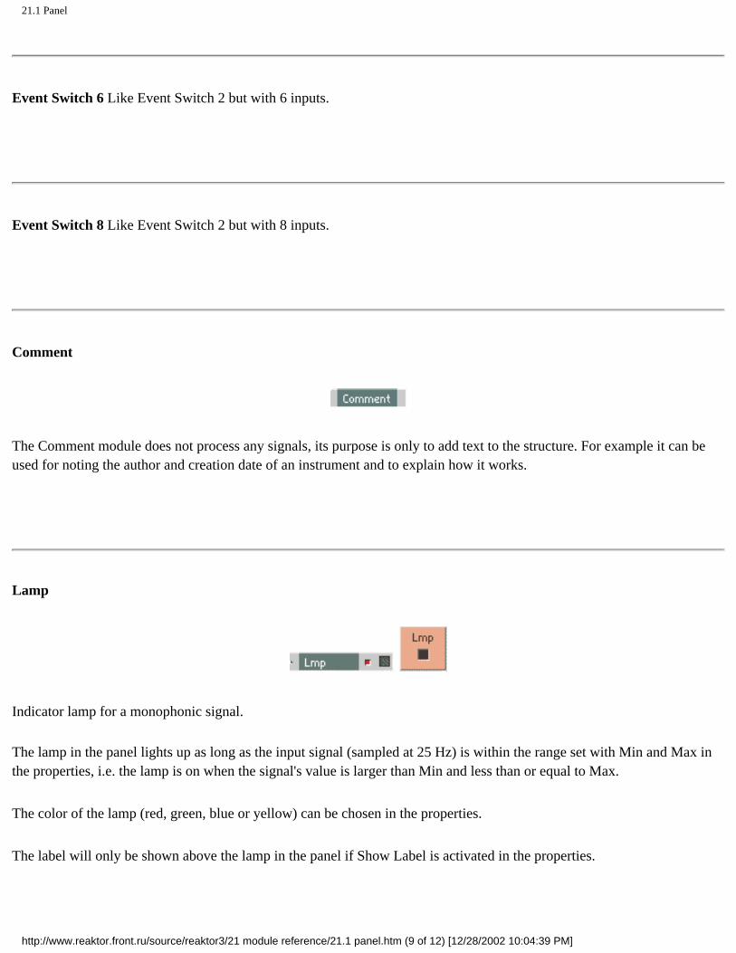
21.1 Panel
Event Switch 6 Like Event Switch 2 but with 6 inputs.
Event Switch 8 Like Event Switch 2 but with 8 inputs.
Comment
The Comment module does not process any signals, its purpose is only to add text to the structure. For example it can be used for noting the author and creation date of an instrument and to explain how it works.
Lamp
Indicator lamp for a monophonic signal.
The lamp in the panel lights up as long as the input signal (sampled at 25 Hz) is within the range set with Min and Max in the properties, i.e. the lamp is on when the signal's value is larger than Min and less than or equal to Max.
The color of the lamp (red, green, blue or yellow) can be chosen in the properties.
The label will only be shown above the lamp in the panel if Show Label is activated in the properties.
http://www.reaktor.front.ru/source/reaktor3/21 module reference/21.1 panel.htm (9 of 12) [12/28/2002 10:04:39 PM]

21.1 Panel
Level Lamp
Indicator lamp for a monophonic signal with logarithmic settings.
The lamp in the panel lights as long as the input level is within the range set with Min and Max (in dB) in the properties, i.e. the lamp is on when the signal's value is larger than Min and less than or equal to Max.
The color of the lamp (red, green, blue or yellow) can be chosen in the properties.
The label will only be shown above the lamp in the panel if Show Label is activated in the properties.
Meter
Value indicator for a monophonic signal.
The value of arriving signal is sampled (at 25 Hz) and displayed on a linear scale. The displayed range is set with Min and Max in the properties.
The label will only be shown above the meter in the panel if Show Label is activated in the properties.
http://www.reaktor.front.ru/source/reaktor3/21 module reference/21.1 panel.htm (10 of 12) [12/28/2002 10:04:39 PM]
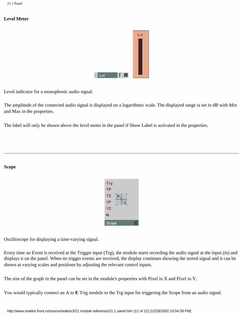
21.1 Panel
Level Meter
Level indicator for a monophonic audio signal.
The amplitude of the connected audio signal is displayed on a logarithmic scale. The displayed range is set in dB with Min and Max in the properties.
The label will only be shown above the level meter in the panel if Show Label is activated in the properties.
Scope
Oscilloscope for displaying a time-varying signal.
Every time an Event is received at the Trigger input (Trg), the module starts recording the audio signal at the input (in) and displays it on the panel. When no trigger events are received, the display continues showing the stored signal and it can be shown at varying scales and positions by adjusting the relevant control inputs.
The size of the graph in the panel can be set in the module's properties with Pixel in X and Pixel in Y.
You would typically connect an A to E Trig module to the Trg input for triggering the Scope from an audio signal.
http://www.reaktor.front.ru/source/reaktor3/21 module reference/21.1 panel.htm (11 of 12) [12/28/2002 10:04:39 PM]

21.1 Panel
Trg: Mono event input for the trigger signal that synchronises the trace.
TP: Mono event input for controlling the offset in time (Time Position) of the trace in milliseconds. The trace starts at the left edge of the display TP ms after the trigger event.
TS: Mono event input for controlling the time scale of the displayed trace. From left to right edge, the display shows TS ms of the signal.
YP: Mono event input for controlling the amplitude offset (Y Position) of the trace. YP = -1 corresponds to the bottom edge of the display, +1 is the top edge.
YS: Mono event input for controlling the amplitude scaling (Y Scale) of the trace. The difference between the signal values at the top and at the bottom of the display is 2 YS. When YP =0 the display shows values between +YS and -YS.
In: Mono audio input for the signal to be displayed.
Bitmap
Allows loading a panel decoration bitmap from a picture file in TGA format (File extension *.tga). The bitmap module has no in or outputs. The display size will be set to the size of the image. It is possible to modify the visible frame in pixels under Appearance/Size in the properties. The image cannot be resized inside Reaktor, for this you need to use external picture editing software.
Select the option Save bitmap with ensemble in the Properties to have the image data stored as part of Reaktor's file.
http://www.reaktor.front.ru/source/reaktor3/21 module reference/21.1 panel.htm (12 of 12) [12/28/2002 10:04:39 PM]

NATIVE INSTRUMENTS: home
Absynth Sounds Add-On
Demos and Update TRAKTOR DJ Studio 2.0.1
Winning the VINYLab
Marius De Vries
01/16/2003Anaheim/USA NAMM Show 2003
Dates Overview
Please enter your email address
Product Overview
Reaktor Reaktor Session Absynth Dynamo
B4 Organ Pro-53 FM7
Kontakt Battery
Spektral Delay
Traktor DJ Studio Traktor DJ Traktor DJ Player
Studio Collection Spektral Delay PTE
Absynth Sounds
Free ensemble, loops, drum samples, presets
The holidays are just around the corner, and Native Instruments would like to thank all of our users. As a small holiday surprise we've prepared a few small download packages: The REAKTOR ensemble Beatslicer, a loop package for TRAKTOR DJ Studio provided by the German label Kanzleramt, a drum kit for KONTAKT and 16 new presets for ABSYNTH. Have fun, happy holidays, and best wishes for the New Year from Native Instruments. Download page...
Reader Awards for KONTAKT and FM7
Native Instruments broke all the records at the 2002 Future Publishing Reader Awards: for the second year in the row NI products seized first, second and third place in the "Best Soft Synth" category. FM7, ABSYNTH and REAKTOR were selected as the best software synthesizers of the year 2002 by the readers of Computer Music, Future Music and four other music magazines. In its first year in the running, KONTAKT made a strong debut by winning the prize for the best software sampler. More...
256 new presets for ABSYNTH
Anyone who’s ever had their hands on ABSYNTH appreciates its breathtaking sonic potential and deep sound shaping abilities. Now the ideal expansion to ABSYNTH's preset library is available with the ABSYNTH Sounds Volume 1 collection. Carefully programmed by six respected sound designers, these 256 brand new sounds will inspire you with their richness and vitality. You’ll find an outstanding selection of new and classic sounds, including pads and atmospheres, loops and sequences,
synthesizers, effects, acoustic sounds, basses, drums and percussion sounds. ABSYNTH Sounds Volume 1 is now available in our Online Shop and at you local dealer. Demo sounds and more info…
Absynth Sounds 1
Click for more info.To see an interactive version, please install Flash 5 or later.
Matt Black
"Traktor is a great tool for digital jockeys. Lots of good
functions, I like the filters and scratching." (Matt Black - part of Coldcut - about TRAKTOR DJ Studio)
Perfect Complements
Music collections encoded and organized with Apple
iTunes™ can be seamlessly mixed with TRAKTOR DJ Studio 2.0
http://www.nativeinstruments.de/index.php?home_us (1 of 3) [12/28/2002 10:04:51 PM]

NATIVE INSTRUMENTS: home
Electr. Instruments Studio Drums Synthetic Drums FM7 Sounds Vol. I B4 Tonewheel Set
Reaktor PC Reaktor Mac Dynamo PC Dynamo Mac Absynth Mac Absynth PC FM7 PC FM7 Mac Pro-53 PC Pro-53 Mac B4 Organ PC/Mac Kontakt PC Kontakt Mac Battery PC Battery Mac Traktor DJ Studio PC Traktor DJ Studio Mac Traktor DJ Spektral Delay PC Spektral Delay Mac Studio Collection NI-Spektral D. PTE
High-end DJ software now available for PC, Mac OS 9, and OS X
Now it's here: Native Instruments proudly presents the latest development in software based DJ mixing: TRAKTOR DJ Studio 2.0, the first NI product ready for Mac OS X. This brand-new DJ software comes packed with unique features to transform any PC or Mac into a powerful DJ setup. Live mixing and mix production using MP3, WAV, AIFF and Audio CD tracks has never been more versatile and exciting. TRAKTOR DJ Studio 2.0 is now available in our Online Shop and at your local dealer. The online updates for registered users of TRAKTOR DJ Studio version 1 are
available as well. Find out more...
Added value: REAKTOR 3 plus Electronic Instruments Vol. 1
Now is the ideal time to enter the vast world of sound design: until the end of December REAKTOR 3 comes packaged with the seven professional instruments of REAKTOR Electronic Instruments Vol. 1. That's a $/Euro 69 value at no extra cost. The ultimate software studio for sound synthesis, sampling and effects processing offers hundreds of virtual synthesizers, samplers, drum machines and effects and allows you to create your own sound machines. The package is now available in the NI Online
Shop and at your authorized dealer. Read more...
Out Now: REAKTOR Electronic Instruments Vol. 1
The latest product of the Sound Line series is here. REAKTOR Electronic Instruments Vol. 1 presents seven first-class instruments that will expand your REAKTOR's sound right out of the box. Several of the world's finest REAKTOR experts developed three powerful synthesizers, three unique effects and a sequenced drum machine. These instruments are
diverse enough to produce stunning arrangements from drums to bass to leads and effects. REAKTOR Electronic Instruments is now available in our Online Shop and is coming soon to your local dealer. Read more…
News Overview
Traktor Bundle
Special offer: The TRAKTOR DJ Studio 2.0 bundle includes the 8
channel USB audio interface GIGAPort AG by Ego Systems Inc.
Techno Animal
"In Kontakt comes a soft sampler that is far beyond both
previous soft sampler competitors and hardware samplers alike..." (Techno Animal)
Best VST Instrument
Reaktor was awarded by Future Music
to be the best VST instrument: "There is one VSTi that stands out: Reaktor. It's the king"
Forums
Discuss NI tools, events,
audio hardware and more. CommuNIcate.
Integration
NI products support VST 2.0, DXi, MAS, FreeMIDI and
DirectConnect for perfect integration into all professional sequencer programs.
http://www.nativeinstruments.de/index.php?home_us (2 of 3) [12/28/2002 10:04:51 PM]

NATIVE INSTRUMENTS: home
http://www.nativeinstruments.de/index.php?home_us (3 of 3) [12/28/2002 10:04:51 PM]

21.2 MIDI
Click here to show toolbars of the Web Online Help System: show toolbars
21.2 MIDI
Note Pitch
Polyphonic event source for the pitch of MIDI Note On events.
A Note On event sets the output to a value determined by the key number (note pitch). The range of the output value is set with Min and Max in the properties dialog window. The resolution is 128 steps. A Note Off event has no effect here.
When using the default range of Min = 0 to Max = 127 and controlling an oscillator's P-input (for logarithmic pitch control) you will play in the common equal tempered tuning. One unit corresponds to one semitone and middle C is at 60. By setting Min and Max to different values, pitch can be skewed or scaled, e.g. for playing in quarter tones.
Pitchbend
Monophonic event source for MIDI Pitchbend (pitchwheel change) events. The resolution is 16384 steps. When the pitch bend controller is in its neutral position, the output value is always 0. The range of the output value for upward or downward pitchbend can be set independently in the properties dialog window. For pitchbend down the range is set with Min and for pitchbend up with Max.
When controlling an oscillator's P-input (for logarithmic pitch control), e.g. after adding to a note pitch value, and with a range of Min = -1 to Max = 1 you can change the pitch up or down one semitone. A range of -12 to 12 means pitchbend within ± 12 semitones which is ± 1 octave.
http://www.reaktor.front.ru/source/reaktor3/21 module reference/21.2 midi.htm (1 of 5) [12/28/2002 10:04:54 PM]
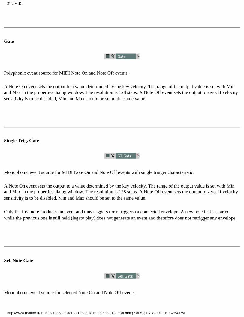
21.2 MIDI
Gate
Polyphonic event source for MIDI Note On and Note Off events.
A Note On event sets the output to a value determined by the key velocity. The range of the output value is set with Min and Max in the properties dialog window. The resolution is 128 steps. A Note Off event sets the output to zero. If velocity sensitivity is to be disabled, Min and Max should be set to the same value.
Single Trig. Gate
Monophonic event source for MIDI Note On and Note Off events with single trigger characteristic.
A Note On event sets the output to a value determined by the key velocity. The range of the output value is set with Min and Max in the properties dialog window. The resolution is 128 steps. A Note Off event sets the output to zero. If velocity sensitivity is to be disabled, Min and Max should be set to the same value.
Only the first note produces an event and thus triggers (or retriggers) a connected envelope. A new note that is started while the previous one is still held (legato play) does not generate an event and therefore does not retrigger any envelope.
Sel. Note Gate
Monophonic event source for selected Note On and Note Off events.
http://www.reaktor.front.ru/source/reaktor3/21 module reference/21.2 midi.htm (2 of 5) [12/28/2002 10:04:54 PM]

21.2 MIDI
A Note On event which has the selected note number sets the output to a value determined by the key velocity. The range of the output value is set with Min and Max in the properties dialog window. The resolution is 128 steps. A Note Off event which has the selected note number sets the output to zero. If velocity sensitivity is to be disabled, Min and Max should be set to the same value.
On Velocity
Polyphonic event source for velocity of MIDI Note On events. A Note On event sets the output to a value determined by the key velocity. The range of the output value is set with Min and Max in the properties dialog window. The resolution is 128 steps.
Off Velocity
Polyphonic event source for the velocity of MIDI Note Off events. A Note Off event sets the output to a value determined by the key release velocity. The range of the output value is set with Min and Max in the properties dialog window. The resolution is 128 steps.
There are very few keyboards that generate a value other than zero for this event.
Controller
Monophonic event source for MIDI Controller events. An event sets the output to a value determined by the position of the controller (e.g. modulation wheel). The number of the controller is set in the properties dialog window with Controller No
http://www.reaktor.front.ru/source/reaktor3/21 module reference/21.2 midi.htm (3 of 5) [12/28/2002 10:04:54 PM]

21.2 MIDI
and the range of the output value is set with Min and Max. The resolution is 128 steps.
The current position of all MIDI controllers (and faders) of an instrument can be stored in a snapshot from where it can be recalled at a later time. If the Snap isolate switch is activated, the controller module's output value will not respond to snapshot recall.
The output of a controller is monophonic and can be used as an event or audio signal.
The numbers of some standard MIDI controllers are:
1 Modulation Wheel
2 Breath Controller
7 Volume
10 Panpot
64 Sustain Switch
65 Portamento Switch
66 Hold Switch (Sostenuto)
See your keyboard's MIDI implementation chart to find out which controllers it can transmit.
Ch. Aftertouch
Monophonic event source for MIDI Channel Aftertouch events. An event sets the output to a value determined by the pressure on all keys. The range of the output value is set with Min and Max in the properties dialog window. The resolution is 128 steps.
Poly Aftertouch
http://www.reaktor.front.ru/source/reaktor3/21 module reference/21.2 midi.htm (4 of 5) [12/28/2002 10:04:54 PM]

21.2 MIDI
Polyphonic event source for MIDI Poly Aftertouch events. An event sets the output to a value determined by the pressure on the key. The value is only set for the particular voice in the REAKTOR instrument which is playing the note associated with the key. The range of the output value is set with Min and Max in the properties dialog window. The resolution is 128 steps.
There are very few keyboards that generate poly aftertouch events.
Sel. Poly AT
Monophonic event source for selected MIDI Poly Aftertouch events.
An event which has the selected note number sets the output to a value determined by the pressure on the key. The number of the key (note number) is set in the properties dialog window with Controller No and the range of the output value is set with Min and Max. The resolution is 128 steps.
There are very few keyboards that generate poly aftertouch events.
The current value can be stored (together with the MIDI controllers and faders) in a snapshot from where it can be recalled at a later time. If the Snap isolate switch is activated, the module's output value will not change on snapshot recall.
Program Change
Monophonic event source for MIDI Program Change events. A MIDI event sets the module's output to the value determined by the transmitted program number. The range of the output value is set with Min and Max in the properties dialog window. The resolution is 128 steps. When using this module, you probably want to turn off Prog. Change Enable in the Instrument Properties so that the MIDI Program Change Events do not also recall snapshots.
http://www.reaktor.front.ru/source/reaktor3/21 module reference/21.2 midi.htm (5 of 5) [12/28/2002 10:04:54 PM]

21.3 MIDI Out
Click here to show toolbars of the Web Online Help System: show toolbars
21.3 MIDI Out
Note Pitch/Gate
Converts a monophonic or polyphonic event signal to MIDI Note events. Each event at the gate input G generates a MIDI message at the MIDI port which REAKTOR uses for output. The value of the event specifies the velocity. An event value of 1 produces a velocity of 127. An event with value zero produces a Note Off event.
The pitch of the Note On and Note Off events is the current value at the pitch input P in the range set with Min and Max. An event with value equal to Min sets the MIDI Note Pitch to 0, an event with value equal to Max sets the MIDI Note Pitch to 127.
Pitchbend
Converts a monophonic event signal to MIDI Pitchbend events. Each event generates a MIDI message at the MIDI port which REAKTOR uses for output. The range of the input value is set with Min and Max. The output resolution is 16384 steps. An event with value equal to Min sets the MIDI Pitchbend value to -8192, an event with value equal to Max sets the MIDI Pitchbend value to +8191.
http://www.reaktor.front.ru/source/reaktor3/21 module reference/21.3 midi out.htm (1 of 3) [12/28/2002 10:04:57 PM]

21.3 MIDI Out
Ch. Aftertouch
Converts a monophonic event signal to MIDI Channel Aftertouch events. Each event generates a MIDI message at the MIDI port which REAKTOR uses for output. The range of the input value is set with Min and Max. The output resolution is 128 steps. An event with value equal to Min sets the MIDI Aftertouch value to 0, an event with value equal to Max sets the MIDI Aftertouch value to 127.
Controller
Converts a monophonic event signal to MIDI Controller events. Each event generates a MIDI message at the MIDI port which REAKTOR uses for output. The number of the controller is set in the properties dialog window with Controller No and the range of the input value is set with Min and Max. The output resolution is 128 steps. An event with value equal to Min sets the MIDI Controller value to 0, an event with value equal to Max sets the MIDI Controller value to 127.
Sel. Poly AT
Converts a monophonic event signal to MIDI Poly Aftertouch events. Each event generates a MIDI message at the MIDI port which REAKTOR uses for output. The number of the key for which to set the pressure (note number) is set in the properties dialog window with Note NO. and the range of the input value is set with Min and Max. The output resolution is 128 steps. An event with value equal to Min sets the aftertouch value to 0, an event with value equal to Max sets the aftertouch value to 127.
There are very few MIDI devices which handle poly aftertouch events.
http://www.reaktor.front.ru/source/reaktor3/21 module reference/21.3 midi out.htm (2 of 3) [12/28/2002 10:04:57 PM]

21.3 MIDI Out
Program Change
Converts a monophonic event signal to MIDI Program Change events. Each event generates a MIDI message at the MIDI port which REAKTOR uses for output. The range of the input value is set with Min and Max. The output resolution is 128 steps. An event with value equal to Min sets the MIDI Program Change value to 0, an event with value equal to Max sets the MIDI Program Change value to 127.
http://www.reaktor.front.ru/source/reaktor3/21 module reference/21.3 midi out.htm (3 of 3) [12/28/2002 10:04:57 PM]

21.4 Constant
Click here to show toolbars of the Web Online Help System: show toolbars
21.4 Constant
Constant
Monophonic event source for a constant value. The value is set with Constant Value in the properties dialog window. The module only sends an event once, that is for initialization when it is activated.
http://www.reaktor.front.ru/source/reaktor3/21 module reference/21.4 constant.htm [12/28/2002 10:04:59 PM]

21.5 +, -, X, /
Click here to show toolbars of the Web Online Help System: show toolbars
21.5 +,-,X,/
This section contains modules for simple arithmetic applied to events and audio sample values.
Audio Invert
Inverter for an audio signal. The output signal is the inverse of the input signal ( Out = -in ).
Simply inverting a sound has no audible effect, except when combining in some way with the uninverted sound. But inverting control signals generally has a very obvious effect.
Audio Add
http://www.reaktor.front.ru/source/reaktor3/21 module reference/21.5 +-x.htm (1 of 7) [12/28/2002 10:05:03 PM]
21.5 +, -, X, /
Audio Add 2
Adder for two audio signals. The output signal is the sum of the two input signals ( Out = ln1 + ln2 ).
Can also be used as a simple two-channel mixer where the level of both channels is fixed at 0 dB.
Audio Add 3 Like Audio Add 2 but with 3 inputs.
Audio Add 4 Like Audio Add 2 but with 4 inputs.
Audio Add 6 Like Audio Add 2 but with 6 inputs.
Audio Add 8 Like Audio Add 2 but with 8 inputs.
Audio Add 16 Like Audio Add 2 but with 16 inputs.
http://www.reaktor.front.ru/source/reaktor3/21 module reference/21.5 +-x.htm (2 of 7) [12/28/2002 10:05:03 PM]

21.5 +, -, X, /
Event Invert
Inverter for an event signal. For each event at the input an event with the inverse value is output ( Out =-ln ).
Event Add
Event Add 2
Adder for two event signals. When an event is received at an input, an event is output whose value is the sum of the current (last received) input values ( Out = ln1 + ln2 ).
Event Add 3 Like Event Add 2 but with 3 inputs.
http://www.reaktor.front.ru/source/reaktor3/21 module reference/21.5 +-x.htm (3 of 7) [12/28/2002 10:05:03 PM]

21.5 +, -, X, /
Event Add 4 Like Event Add 2 but with 4 inputs.
Event Add 6 Like Event Add 2 but with 6 inputs.
Audio Mult
Audio Mult 2
Multiplier for two audio signals. The output signal is the product of the two input signals (Out - ln1 • ln2 ). The typical application is as an amplifier controlled by a signal (corresponds to VCA in analog synthesizers) when an audio signal is fed to one input and an amplification factor to the other.
When an input is not connected (multiplication with zero) the output value is always zero.
Can also be used to compute the square of a signal when the same signal is fed to both inputs ( Out = in • in = In2 ).
When two different sounds are connected to the inputs, the output is the ring modulation of the two sounds.
http://www.reaktor.front.ru/source/reaktor3/21 module reference/21.5 +-x.htm (4 of 7) [12/28/2002 10:05:03 PM]

21.5 +, -, X, /
Audio Mult 3
Multiplier for three audio signals. The output signal is the product of the three input signals ( Out = ln1 • ln2 • ln3 ).
When an input is not connected (multiplication with zero) the output value is always zero.
Audio Mult 4 Like Audio Mult 3 but with 4 inputs.
Audio Mult 6 Like Audio Mult 3 but with 6 inputs.
Event Mult
Event Mult 2
Multiplier for two event signals. When an event is received at an input. an event is output whose value is the product of the current (last received) input values ( Out = ln1 • ln2 ).
When an input is not connected (multiplication with zero) the outpul value is always zero.
http://www.reaktor.front.ru/source/reaktor3/21 module reference/21.5 +-x.htm (5 of 7) [12/28/2002 10:05:03 PM]

21.5 +, -, X, /
Can also be used to compute the square of a signal when the same signal is fed to both inputs ( Out = in • in = In2 ).
Event Mult 3 Like Event Mult 2 but with 3 inputs.
Event Mult 4 Like Event Mult 2 but with 4 inputs.
Audio I/x
The output is one divided by the input.
Be careful with small input values (near zero) because the output values become very large. If the input signal is exactly zero the output is also set to zero.
Processing sound signals does not normally yield anything useful. The module is rather meant for processing control signals (which don't come near zero).
Audio x/y
http://www.reaktor.front.ru/source/reaktor3/21 module reference/21.5 +-x.htm (6 of 7) [12/28/2002 10:05:03 PM]

21.5 +, -, X, /
The output is the upper input divided by the lower input.
Be careful with small values (near zero) at the lower input because the output values become very large. If the input signal is exactly zero the output is also set to zero.
Dividing by sound signals does not normally yield anything useful.
Whenever possible use a multiplier instead of a divider because the CPU load will be significantly less. For example, rather than dividing by a constant or an event signal, invert the event signal (1/x) and multiply audio with the result.
Event I/x
The output is one divided by the input. Exception: If the input signal is zero, the output is set to zero.
Event x/y
The output is the first input divided by the second input. Exception: If the second input signal is zero, the output is set to zero.
http://www.reaktor.front.ru/source/reaktor3/21 module reference/21.5 +-x.htm (7 of 7) [12/28/2002 10:05:03 PM]

21.6 Mixer
Click here to show toolbars of the Web Online Help System: show toolbars
21.6 Mixer
Amp
Amplifier for an audio signal. The input signal is amplified (or attenuated) by the set amount (in dB). At 0 dB the output signal is the same as the input signal.
Lvl: Logarithmic event input for controlling the gain, value in dB. When the values negative, the output signal is smaller than the input signal.
In: Audio signal input
Out: Audio signal output for the amplified signal ( Out = In • 10Lvl/20).
Mixer
http://www.reaktor.front.ru/source/reaktor3/21 module reference/21.6 mixer.htm (1 of 4) [12/28/2002 10:05:06 PM]

21.6 Mixer
Mixer 2
Mixer for two audio signals. The two input signals are amplified (or attenuated) by their respective amounts and then summed to form the output.
Lvl1, Lvl2: Logarithmic event input for controlling the gain, value in dB.
ln1, ln2: Audio signal inputs
Out: Audio signal output for the mixed signal ( Out = In1 • 10Lvl/20 + In2 • 10Lvl2/20)
Mixer 3 Like Mixer 2 but with 3 inputs.
Mixer 4 Like Mixer 2 but with 4 inputs.
Mixer 5 Like Mixer 2 but with 5 inputs.
Mixer 6 Like Mixer 2 but with 6 inputs.
Mixer 8 Like Mixer 2 but with 8 inputs.
If a mixer with more channels is needed, simply use several smaller mixers and add their outputs.
Crossfade
http://www.reaktor.front.ru/source/reaktor3/21 module reference/21.6 mixer.htm (2 of 4) [12/28/2002 10:05:06 PM]

21.6 Mixer
Crossfade module for two audio signals. The output signal is the weighted sum (linear interpolation) of the two input signals. The ratio of their respective amounts in the output is adjustable.
X: Audio control input for the mixing ratio. Value between 0 ( Out = ln1 ) and 1 ( Out - ln2 ).
ln1, ln2: Inputs for the two audio signals to be mixed.
Out: Audio signal output for the mixed signal (Out = (l - X) ln1+X ln2).
Stereo Pan
Left-right panner.
By changing the signal level at the two outputs the input signal is positioned in the stereo field. The sum of the L and R output values is always exactly twice the input value, i.e. the input is split across the two outputs at a variable ratio.
Pan: Audio control input for the left-right position. Value -1 = left, 0 = center, 1 = right.
In: Audio signal input for the signal to be positioned in stereo.
L: Audio signal output for the left channel signal.
R: Audio signal output for the right channel signal.
Stereo Amp
Amplifier for an audio signal with integrated left-right panner. The input signal is amplified (or attenuated) by the set amount (in dB). By changing the signal level at the two outputs the input signal is positioned in the stereo field. The sum of the L and R output values is always exactly twice the amplified input value, i.e. the input is split across the two outputs at a variable ratio.
Lvl: Logarithmic event input for controlling the gain, value in dB. When the value is negative, the output signal is smaller than the input signal.
Pan: Event control input for the left-right position. Value -1 = left, 0 = center, 1 = right.
In: Audio input for the signal to be amplified and positioned in stereo.
L: Audio signal output for the amplified left channel signal.
R: Audio signal output for the amplified right channel signal.
http://www.reaktor.front.ru/source/reaktor3/21 module reference/21.6 mixer.htm (3 of 4) [12/28/2002 10:05:06 PM]

21.6 Mixer
Scanner
Scanner for eight audio signals. The inputs are scanned by sweeping the value at the Pos input. When Pos is an integer, you get just one input signal, otherwise a mix of two inputs. The output signal is obtained by crossfading between the two inputs whose index is closest to the Value at the POS input.
When Wrap mode is selected in the Properties, POS wraps around so that 8 is the same as 0, 9 is 1 etc.
The scanner makes nice effects when the inputs are fed from the Multitap Delay and the scan position is controlled by a Ramp Oscillator.
POS: Audio control input for selecting the input(s) to scan. Pos = 0 selects In0, POS = 1 selects ln1, POS =0.5 gives a mix of In0 and In1.Typ. Range: [ 0 ... 7 ]
ln 0...7: Inputs for the eight audio signals to be scanned.
Out: Audio signal output for the scanned signal.
http://www.reaktor.front.ru/source/reaktor3/21 module reference/21.6 mixer.htm (4 of 4) [12/28/2002 10:05:06 PM]

21.7 Oscillators
Click here to show toolbars of the Web Online Help System: show toolbars
21.7 Oscillators
All of REAKTOR'S oscillators can run at any frequency, from 0 Hz (standstill) through the entire audio range right up to the limit set by the sample rate. Like this they are all equally suited for use as LFOs or for producing sound waves. When using an oscillator as an LFO to modulate another module's input which is of the type that only accepts events (e.g. P as opposed to F) you need to insert an A to E (perm) module for conversion.
Sawtooth
Oscillator for sawtooth waveform with logarithmic pitch control and linear amplitude modulation.
P: Logarithmic event input for controlling the pitch (oscillator frequency). Value in semitones (69 = 440 Hz).
A: Audio input for controlling the amplitude. The output signal moves between +A and -A.
Out: Audio signal output for the sawtooth waveform.
SawFM
http://www.reaktor.front.ru/source/reaktor3/21 module reference/21.7 oscillators.htm (1 of 22) [12/28/2002 10:05:17 PM]

21.7 Oscillators
Oscillator for sawtooth waveform with logarithmic pitch control, linear frequency modulation (FM) and linear amplitude modulation.
P: Logarithmic event input for controlling the pitch (oscillator frequency). Value in semitones (69 = 440 Hz).
F: Audio input for linear frequency modulation. Value in Hz. P and F together determinant oscillator frequency.
A: Audio input for controlling the amplitude. The output signal moves between +A and -A.
Out: Audio signal output for the sawtooth waveform.
Saw Sync
Oscillator for sawtooth waveform with synchronization, logarithmic pitch control, linear frequency modulation (FM) and linear amplitude modulation.
Whenever the synchronization signal leaves zero to positive values (rising edge) the phase of the oscillator is reset to a position specified by the phase input.
P: Logarithmic event input for controlling the pitch (oscillator frequency). Value in semitones (69 = 440 Hz).
F: Audio input for linear frequency modulation. Value in Hz. P and F together determine the oscillator frequency.
A: Audio input for controlling the amplitude. The output signal moves between +A and -A.
Snc: Audio input for controlling synchronization of the waveform. A rising edge restarts the oscillator.
Ph: Input for specifying the phase (position in the waveform) to which the oscillator is reset when synchronization occurs.
Out: Audio signal output for the sawtooth waveform.
http://www.reaktor.front.ru/source/reaktor3/21 module reference/21.7 oscillators.htm (2 of 22) [12/28/2002 10:05:17 PM]

21.7 Oscillators
Saw Pulse
Oscillator for variable sawtooth/needle-pulse waveform with logarithmic pitch control and linear amplitude modulation. The slope of the ramp is variable and with it the shape of the waveform can be changed from a normal sawtooth to a short triangular pulse.
P: Logarithmic event input for controlling the pitch (oscillator frequency). Value in semitones (69 = 440 Hz).
A: Audio input for controlling the amplitude. The output signal moves between +A and -A.
Slp: Audio input for controlling the slope of the waveform. A value of 0 produces a normal sawtooth, a larger value shortens the ramp to a short spike (needle).
Out: Audio signal output for the sawtooth/pulse waveform.
Bi-Saw
Oscillator for bipolar sawtooth waveform with zero-phase. With logarithmic pitch control, pulse width modulation (PWM) and linear amplitude modulation.
P: Logarithmic event input for controlling the pitch (oscillator frequency). Value in semitones (69 = 440 Hz).
A: Audio input for controlling the amplitude. The output signal moves between +A and -A.
W: Audio input for controlling the pulse width (PWM). Range of values is 0 to about 6. Normal sawtooth-wave at W = 0, larger W results in a shorter pulse and a longer zero-phase.
Out: Audio signal output for the bipolar sawtooth waveform with zero-phase.
http://www.reaktor.front.ru/source/reaktor3/21 module reference/21.7 oscillators.htm (3 of 22) [12/28/2002 10:05:17 PM]

21.7 Oscillators
Triangle
Oscillator for symmetric triangle waveform with logarithmic pitch control and linear amplitude modulation.
P: Logarithmic event input for controlling the pitch (oscillator frequency). Value in semitones (69 = 440 Hz).
A: Audio input for controlling the amplitude. The output signal moves between +A and -A.
Out: Audio signal output for the triangle waveform.
TriFM
Oscillator for symmetric triangle waveform with logarithmic pitch control, linear frequency modulation (FM) and linear amplitude modulation.
P: Logarithmic event input for controlling the pitch (oscillator frequency). Value in semitones (69 = 440 Hz).
F: Audio input for linear frequency modulation. Value in Hz. P and F together determine the oscillator frequency.
A: Audio input for controlling the amplitude. The output signal moves between +A and -A. Out: Audio signal output for the triangle waveform.
Tri Sync
http://www.reaktor.front.ru/source/reaktor3/21 module reference/21.7 oscillators.htm (4 of 22) [12/28/2002 10:05:17 PM]

21.7 Oscillators
Oscillator for symmetric triangle waveform with synchronization, logarithmic pitch control, linear frequency modulation (FM) and linear amplitude modulation.
Whenever the synchronization signal leaves zero to positive values (rising edge) the phase of the oscillator is reset to a position specified by the phase input.
P: Logarithmic event input for controlling the pitch (oscillator frequency). Value in semitones (69 = 440 Hz).
F: Audio input for linear frequency modulation. Value in Hz. P and F together determine the oscillator frequency.
A: Audio input for controlling the amplitude. The output signal moves between +A and -A.
Snc: Audio input for controlling synchronization of the waveform. A rising edge restarts the oscillator.
Ph: Input for specifying the phase (position in the waveform) to which the oscillator is reset when synchronization occurs.
Out: Audio signal output for the triangle waveform.
Tri/Par Symm
Oscillator for variable triangle and parabolic (near to sine) signals, with logarithmic pitch (P) control and linear amplitude (A) modulation. The symmetry is adjustable by (W). Setting the symmetry (with W) allows a range of waveforms from symmetric with few harmonics to asymmetric with a broader spectrum.
P: Logarithmic event input for controlling the pitch (oscillator frequency). Value in semitones (69 = 440 Hz).
A: Audio input for controlling the amplitude. The output signal moves between +A and -A.
http://www.reaktor.front.ru/source/reaktor3/21 module reference/21.7 oscillators.htm (5 of 22) [12/28/2002 10:05:17 PM]

21.7 Oscillators
W: Event input for controlling the symmetry of the waveform. A value of-1 producesa rising-ramp sawtooth, 0 produces a symmetrical triangle and +1 a falling-ramp sawtooth.
Tri: Audio signal output for the triangle signal.
Par: Audio signal output for the parabolic signal.
Parabol
Oscillator for parabolic waveform with logarithmic pitch control and linear amplitude modulation. The waveform consists of two halves that are each a section of a parabola. The oscillator sounds like a sine wave with some added odd numbered overtones at very low level. In many cases it can be used as replacement for a sine generator with less computational load.
P: Logarithmic event input for controlling the pitch (oscillator frequency). Value in semitones (69 = 440 Hz).
A: Audio input for controlling the amplitude. The output signal moves between +A and -A.
Out: Audio signal output for the parabolic waveform.
ParFM
Oscillator for parabolic waveform with logarithmic pitch control, linear frequency modulation (FM) and linear amplitude modulation. The oscillator sounds like a sine wave with some added odd numbered overtones at very low level. In many cases it can be used as replacement for a sine generator with less computational load.
P: Logarithmic event input for controlling the pitch (oscillator frequency). Value in semitones (69 = 440 Hz).
http://www.reaktor.front.ru/source/reaktor3/21 module reference/21.7 oscillators.htm (6 of 22) [12/28/2002 10:05:17 PM]

21.7 Oscillators
F: Audio input for linear frequency modulation. Value in Hz. P and F together determinant oscillator frequency.
A: Audio input for controlling the amplitude. The output signal moves between +A and -A.
Out: Audio signal output for the parabolic waveform.
Par Sync
Oscillator for parabolic waveform with synchronization, logarithmic pitch control, linear frequency modulation (FM) and linear amplitude modulation.
Whenever the synchronization signal leaves zero to positive values (rising edge) the phase of the oscillator is reset to a position specified by the phase input.
P: Logarithmic event input for controlling the pitch (oscillator frequency). Value in semitones (69 = 440 Hz).
F: Audio input for linear frequency modulation. Value in Hz. P and F together determinethe oscillator frequency.
A: Audio input for controlling the amplitude. The output signal moves between +A and -A.
Snc: Audio input for controlling synchronization of the waveform. A rising edge restarts the oscillator.
Ph: Input for specifying the phase (position in the waveform) to which the oscillator is reset when synchronization occurs.
Out: Audio signal output for the parabolic waveform.
Par PWM
http://www.reaktor.front.ru/source/reaktor3/21 module reference/21.7 oscillators.htm (7 of 22) [12/28/2002 10:05:17 PM]

21.7 Oscillators
Oscillator for variable parabolic waveform with logarithmic pitch control and linear amplitude modulation. The ratio between the length of the upper and lower parts of the curve can be controlled, and with it the waveform can be changed from a normal symmetric parabolic wave to a simple parabola.
This variable waveform is also particularly effective when used as an LFO.
P: Logarithmic event input for controlling the pitch (oscillator frequency). Value in semitones (69 = 440 Hz).
A: Audio input for controlling the amplitude. The output signal moves between +A and -A.
W: Event input for controlling the symmetry of the waveform. A value of -1 produces parabolas open downward, 0 a normal sym
Out: metric parabolic wave and +1 parabolas open upward. Audio signal output for the variable parabolic waveform.
Sine
Oscillator for pure sine waveform with logarithmic pitch control and linear amplitude modulation.
If the sine tone does not need to be completely pure, the parabolic oscillator makes a good replacement with less computational load.
P: Logarithmic event input for controlling the pitch (oscillator frequency). Value in semitones (69 = 440 Hz).
A: Audio input for controlling the amplitude. The output signal moves between +A and -A.
Out: Audio signal output for the sine waveform.
http://www.reaktor.front.ru/source/reaktor3/21 module reference/21.7 oscillators.htm (8 of 22) [12/28/2002 10:05:17 PM]

21.7 Oscillators
Sine FM
Oscillator for pure sine waveform with logarithmic pitch control, linear frequency modulation (FM) and linear amplitude modulation.
If the sine tone does not need to be completely pure, the parabolic oscillator makes a good replacement with less computational load.
P: Logarithmic event input for controlling the pitch (oscillator frequency). Value in semitones (69 = 440 Hz).
F: Audio input for linear frequency modulation. Value in Hz. P and F together determinant oscillator frequency.
A: Audio input for controlling the amplitude. The output signal moves between +A and -A.
Out: Audio signal output for the sine waveform.
Sine Sync
Oscillator for pure sine waveform with synchronization, logarithmic pitch control, linear frequency modulation (FM) and linear amplitude modulation.
Whenever the synchronization signal leaves zero to positive values (rising edge) the phase of the oscillator is reset to a position specified by the phase input.
If the sine tone does not need to be completely pure, the parabolic oscillator makes a good replacement with less computational load.
http://www.reaktor.front.ru/source/reaktor3/21 module reference/21.7 oscillators.htm (9 of 22) [12/28/2002 10:05:17 PM]

21.7 Oscillators
P: Logarithmic event input for controlling the pitch (oscillator frequency). Value in semitones (69 = 440 Hz).
F: Audio input for linear frequency modulation. Value in Hz. P and F together determinethe oscillator frequency.
A: Audio input for controlling the amplitude. The output signal moves between +A and -A.
Snc: Audio input for controlling synchronization of the waveform. A rising edge restarts the oscillator.
Ph: Input for specifying the phase (position in the waveform) to which the oscillator is reset when synchronization occurs. Ph = 0: Phase = 0 deg (middle of rising slope), Ph = 0.5: Phase = 180 deg (middle of falling slope), Ph = 1: Phase = 360 deg (same as 0 deg).
Out: Audio signal output for the sine waveform.
Multi-Sine
Oscillator for Additive Synthesis. A waveform is built up in its harmonics by layering individual sine waves. For each component, the amplitude A and the frequency multiple F can be set.
P: Logarithmic event input for controlling the pitch (oscillator frequency). Value in semitones (69 = 440 Hz).
F1: Input for the frequency factor (harmonic number) of the first sine wave. Scale: multiple of fundamental frequency. Typ. Range: [ 0 ...20J.
A1: Input for linear amplitude control of the first sine wave. Can also be used for tremolo and ring modulation. Typ. Range: [ 0 ... 1 ].
F2: Input for the frequency factor (harmonic number) of the second sine wave. Scale: multiple of fundamental frequency. Typ. Range-[0...20].
A2: Input for linear amplitude control of the second sine wave. Can also be used for tremolo and ring modulation. Typ. Range: [ 0 ... 1 ].
http://www.reaktor.front.ru/source/reaktor3/21 module reference/21.7 oscillators.htm (10 of 22) [12/28/2002 10:05:17 PM]
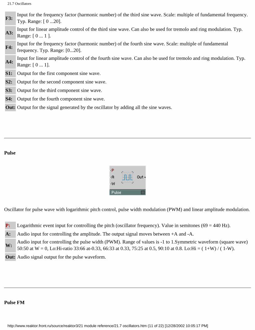
21.7 Oscillators
F3: Input for the frequency factor (harmonic number) of the third sine wave. Scale: multiple of fundamental frequency. Typ. Range: [ 0 ...20].
A3: Input for linear amplitude control of the third sine wave. Can also be used for tremolo and ring modulation. Typ. Range: [ 0 ... 1 ].
F4: Input for the frequency factor (harmonic number) of the fourth sine wave. Scale: multiple of fundamental frequency. Typ. Range: [0...20].
A4: Input for linear amplitude control of the fourth sine wave. Can also be used for tremolo and ring modulation. Typ. Range: [ 0 ... 1].
S1: Output for the first component sine wave.
S2: Output for the second component sine wave.
S3: Output for the third component sine wave.
S4: Output for the fourth component sine wave.
Out: Output for the signal generated by the oscillator by adding all the sine waves.
Pulse
Oscillator for pulse wave with logarithmic pitch control, pulse width modulation (PWM) and linear amplitude modulation.
P: Logarithmic event input for controlling the pitch (oscillator frequency). Value in semitones (69 = 440 Hz).
A: Audio input for controlling the amplitude. The output signal moves between +A and -A.
W: Audio input for controlling the pulse width (PWM). Range of values is -1 to 1.Symmetric waveform (square wave) 50:50 at W = 0, Lo:Hi-ratio 33:66 at-0.33, 66:33 at 0.33, 75:25 at 0.5, 90:10 at 0.8. Lo:Hi = ( 1+W) / ( 1-W).
Out: Audio signal output for the pulse waveform.
Pulse FM
http://www.reaktor.front.ru/source/reaktor3/21 module reference/21.7 oscillators.htm (11 of 22) [12/28/2002 10:05:17 PM]

21.7 Oscillators
Oscillator for pulse wave with logarithmic pitch control, linear frequency modulation (FM), pulse width modulation (PWM) and linear amplitude modulation.
P: Logarithmic event input for controlling the pitch (oscillator frequency). Value in semitones (69 = 440 Hz).
F: Audio input for linear frequency modulation. Value in Hz. P and F together determine oscillator frequency.
A: Audio input for controlling the amplitude. The output signal moves between +A and -A.
W: Audio input for controlling the pulse width (PWM). Range of values is -1 to 1 .Symmetric waveform (square wave) 50:50 at W = 0, Lo:Hi-ratio 33:66 at-0.33, 66:33 at 0.33, 75:25 at 0.5, 90:10 at0.8.Lo:Hi=( 1+W)/(1-W).
Out: Audio signal output for the pulse waveform.
Pulse Sync
Oscillator for pulse wave with synchronization, logarithmic pitch control, linear frequency modulation (FM), pulse width modulation (PWM) and linear amplitude modulation.
Whenever the synchronization signal leaves zero to positive values (rising edge) the phase of the oscillator is reset to a position specified by the phase input.
P: Logarithmic event input for controlling the pitch (oscillator frequency). Value in semitones (69 = 440 Hz).
F: Audio input for linear frequency modulation. Value in Hz. P and F together determinethe oscillator frequency.
A: Audio input for controlling the amplitude. The output signal moves between +A and -A.
http://www.reaktor.front.ru/source/reaktor3/21 module reference/21.7 oscillators.htm (12 of 22) [12/28/2002 10:05:17 PM]

21.7 Oscillators
W: Audio input for controlling the pulse width (PWM). Range of values is -1 to 1. Symmetric waveform (square wave) 50:50 at W = 0, Lo:Hi-ratio 33:66 at-0.33, 66:33 at 0.33, 75:25 at 0.5, 90:10 at 0.8. Lo:Hi = ( 1 +W) / ( 1-W).
Snc: Audio input for controlling synchronization of the waveform. A rising edge restarts the oscillator.
Ph: Input for specifying the phase (position in the waveform) to which the oscillator is reset when synchronization occurs.
Out: Audio signal output for the pulse waveform.
Pulse 1-ramp
Oscillator for rectangular trapezoid waveform with logarithmic pitch control, linear frequency modulation (FM), pulse width modulation (PWM) and linear amplitude modulation. The waveform is a mixture of pulse and sawtooth: The rising edge of a pulse wave can be flattened and its slope adjusted. The falling edge is vertical.
P: Logarithmic event input for controlling the pitch (oscillator frequency). Value in semitones (69 = 440 Hz).
F: Audio input for linear frequency modulation. Value in Hz. P and F together determine oscillator frequency.
.A: Audio input for controlling the amplitude. The output signal moves between +A and -A.
W: Audio input for controlling the pulse width (PWM). Range of values is -1 to 1.
Slp: Audio input for controlling the slope of the rising edge of the waveform. When Slp is zero (or when the input is not connected) the waveform does not rise and the output is always zero, i.e.
Out: there is no sound. Typical range of values: 1 ... 20 Audio signal output for the trapezoid waveform.
Pulse 2-ramp
http://www.reaktor.front.ru/source/reaktor3/21 module reference/21.7 oscillators.htm (13 of 22) [12/28/2002 10:05:17 PM]

21.7 Oscillators
Oscillator for trapezoid waveform with logarithmic pitch control, linear frequency modulation (FM), pulse width modulation (PWM) and linear amplitude modulation. The waveform is a mixture of pulse, sawtooth and triangle: Both edges of a pulse wave can be flattened and their slope adjusted.
P: Logarithmic event input for controlling the pitch (oscillator frequency). Value in semitones (69 = 440 Hz).
F: Audio input for linear frequency modulation. Value in Hz. P and F together determinethe oscillator frequency.
A: Audio input for controlling the amplitude. The output signal moves between +A and -A.
W: Audio input for controlling the pulse width (PWM). Range of values is -1 to 1.
Up: Audio input for controlling the slope of the rising edge of the waveform.
Dn: Audio input for controlling the slope of the falling edge of the waveform.
Out: Audio signal output for the trapezoid waveform.
Bi-Pulse
Oscillator for bipolar pulse wave with zero-phase. With logarithmic pitch control, pulse width modulation (PWM) and linear amplitude modulation.
P: Logarithmic event input for controlling the pitch (oscillator frequency). Value in semitones (69 = 440 Hz).
A: Audio input for controlling the amplitude. The output signal moves between +A and -A.
W: Audio input for controlling the pulse width (PWM). Range of values is 0 to 1 .Symmetric waveform (square wave) 50:50 at W = 0, larger W results in a shorterpulse and longer zero-phase.
Out: Audio signal output for the bipolar pulse waveform.
http://www.reaktor.front.ru/source/reaktor3/21 module reference/21.7 oscillators.htm (14 of 22) [12/28/2002 10:05:17 PM]

21.7 Oscillators
Impulse
Oscillator for impulse train signal with logarithmic pitch control (P) and linear amplitude modulation (A).
P: Logarithmic event input for controlling the pitch (oscillator frequency). Value in semitones (69 = 440 Hz).
A: Audio input for controlling the amplitude.
Out: Audio signal output for the impulse waveform.
Impulse FM
Oscillator for impulse train signal with logarithmic pitch control (P), linear frequency modulation (F) and linear amplitude modulation (A).
P: Logarithmic event input for controlling the pitch (oscillator frequency). Value in semitones (69 = 440 Hz).
F: Audio input for linear frequency modulation. Value in Hz. P and F together determine oscillator frequency.
A: Audio input for controlling the amplitude.
Out: Audio signal output for the impulse waveform.
http://www.reaktor.front.ru/source/reaktor3/21 module reference/21.7 oscillators.htm (15 of 22) [12/28/2002 10:05:17 PM]

21.7 Oscillators
Impulse Sync
Oscillator for synchronizable impulse train signal with logarithmic pitch control (P), linear frequency modulation (F), linear amplitude modulation (A) and Sync input (Snc).
Whenever the synchronization signal leaves zero to positive values (rising edge) the phase of the oscillator is reset to a position specified by the phase input.
P: Logarithmic event input for controlling the pitch (oscillator frequency). Value in semitones (69 = 440 Hz).
F: Audio input for linear frequency modulation. Value in Hz. P and F together determinethe oscillator frequency.
A: Audio input for controlling the amplitude.
Snc: Audio input for controlling synchronization of the waveform. A rising edge restarts the oscillator.
Ph: Input for specifying the phase (position in the waveform) to which the oscillator is reset when synchronization occurs.
Out: Audio signal output for the impulse waveform.
Noise
Noise generator. Produces white noise, i.e. a random signal containing equal amounts of all possible frequency components. The signal consists of only two values, A/2 and -A/2, but which appear in a random sequence.
A: Audio input for controlling the amplitude of the output signal.
http://www.reaktor.front.ru/source/reaktor3/21 module reference/21.7 oscillators.htm (16 of 22) [12/28/2002 10:05:17 PM]

21.7 Oscillators
Out: Audio signal output for the noise waveform.
Random
Random value generator. Produces step waveform where the level of each step is random in the given interval with equal distribution. It works like a noise generator with uniform distribution followed by a sample & hold circuit clocked at a regular frequency.
P: Logarithmic event input for controlling the step rate (sample & hold frequency). Value in semitones (69 = 440 Hz).
A: Audio input for controlling the amplitude. The output signal is a random value between +A and -A.
Out: Audio signal output for the random step waveform.
Multistep
Geiger
Generates events at random intervals, much like a Geiger Counter radiation particle detector. The average rate of events can be controlled at the P input. Rnd controls the randomness of the event timing.
http://www.reaktor.front.ru/source/reaktor3/21 module reference/21.7 oscillators.htm (17 of 22) [12/28/2002 10:05:17 PM]

21.7 Oscillators
P: Control input for logarithmic control of the average rate or density of the randomly occurring output events. Typ. range: [ -50 ... 50]
Rnd: Control input for the randomness of the event distribution: 0 = completely random, 1 = completely regular. Typ. range: [ 0 ... 1 ]
Out: Audio output for randomly timed clicks.
Out: Output for the randomly timed events. Use to trigger an envelope (G), for example.
Multi-Step
4-Step
Oscillator for 4-step waveform with logarithmic pitch control and linear amplitude modulation. The level of each step can be set independent of the others.
P: Logarithmic event input for controlling the pitch (oscillator frequency). Value in semitones (69 = 440 Hz).
A: Audio input for controlling the amplitude. The output signal moves between +A and -A.
S1: Audio input for controlling the level of the first step.
S2: Audio input for controlling the level of the second step.
S3: Audio input for controlling the level of the third step.
S4: Audio input for controlling the level of the fourth step.
Out: Audio signal output for the step waveform.
http://www.reaktor.front.ru/source/reaktor3/21 module reference/21.7 oscillators.htm (18 of 22) [12/28/2002 10:05:17 PM]

21.7 Oscillators
5-Step Like 4-Step but with 5 steps.
6-Step Like 4-Step but with 6 steps.
8-Step Like 4-Step but with 8 steps.
Multi-Ramp
4-Ramp
http://www.reaktor.front.ru/source/reaktor3/21 module reference/21.7 oscillators.htm (19 of 22) [12/28/2002 10:05:17 PM]

21.7 Oscillators
Oscillator for 4-ramp waveform with logarithmic pitch control and linear amplitude modulation. The level of each of the breakpoints which are connected by ramps can be set independent of the others.
P: Logarithmic event input for controlling the pitch (oscillator frequency). Value in semitones (69 = 440 Hz).
A: Audio input for controlling the amplitude. The output signal moves between +A and -A.
S1: Event input for controlling the level of the first breakpoint.
S2: Event input for controlling the level of the second breakpoint.
S3: Event input for controlling the level of the third breakpoint.
S4: Event input for controlling the level of the fourth breakpoint.
Out: Audio signal output for the ramp waveform.
5-Ramp Like 4-Ramp but with 5 ramps.
6-Ramp Like 4-Ramp but with 6 ramps.
8-Ramp Like 4-Ramp but with 8 ramps.
Ramp Sequencer
http://www.reaktor.front.ru/source/reaktor3/21 module reference/21.7 oscillators.htm (20 of 22) [12/28/2002 10:05:17 PM]

21.7 Oscillators
Oscillator to produce a ramp waveform, typically used as a control signal, for example to use an Audio Table module as a waveform oscillator. The signal ramps up from 0 to A and then resets instantly. There is no anti-aliasing or other complications.
F: Audio input for control of the oscillator frequency in Hz. To control the pitch in semitones, use an Event Expon. (F) module.
A: Input for controlling the amplitude of the ramp signal. Typ. Value: 1
Snc: Audio input for controlling synchronization of the waveform. A rising edge resets the oscillator to Ph.
Ph: Audio input for the synchronization phase. When the oscillator is synchronised, its output jumps to this value times A. Typ. Range: 0...1
Out: Audio output for the ramp signal. Range O...A
Audio Table
Holds a table of data values. The table can be read out as an audio signal, audio can be stored in the table and the table's content can be displayed and edited graphically . The table can be 1-dimensional (a row of values) adressed by X, or 2-dimensional (a matrix of rows and columns, or a set of independent rows) adressed by X and Y.
The value at the output is taken from the table by reading at the position given by the inputs RX and RY. A signal at the
http://www.reaktor.front.ru/source/reaktor3/21 module reference/21.7 oscillators.htm (21 of 22) [12/28/2002 10:05:17 PM]

21.7 Oscillators
module's in-port are stored in individual cells of the table according to the write position given by the inputs WX and WY.
X is the horizontal position from left to right and Y is the vertical position from top to bottom. The count always starts at 0 for the first element.
The module's panel display can show all the data or a limited region of it. Many options in the properties allow customizing the behaviour.
For full details on properties, menus and keyboard shortcuts, please see the section Table Modules on page 160.
RX: Audio input for the X-position of a table cell from which the data is read.
RY: Audio input for the Y-position of a table cell from which the data is read. This is used in 2D-mode or for addressing the row number if more than one row exists.
WX: Audio input for the X-position of a table cell in which the data is written.
WY: Audio input for the Y-position of a table cell in which the data is written.
W: Audio input for activating table write operation.
In: Audio input for the signal to be written into the table. When the value at W is bigger than 0, the value at in is written into the table at the position given by WX and WY.
XO: Event input for the horizontal offset of the displayed data region. XO controls the data position that appears in the display (according to View Alignment). The value of XO is in the units specified in properties.
XR: Event input for the horizontal range of the displayed data region. XR controls how many units of data fit in the display, i.e. it lets you zoom into the data.
YO: Event input for the vertical offset of the displayed data region. YO controls the data position that appears in the display (according to View Alignment). The value of YO is in the units specified in properties.
YR: Event input for the vertical range of the displayed data region in 2D-mode. YR controls how many units of data fit in the display, i.e. it lets you zoom into the data.
Out: Audio output for signal read from the table at the position controlled by the RX and RY inputs.
DX: Event output for the size of the horizontal table rows in units.
DY: Event output for the size of the vertical table columns in units.
http://www.reaktor.front.ru/source/reaktor3/21 module reference/21.7 oscillators.htm (22 of 22) [12/28/2002 10:05:17 PM]

21.8 Samplers
Click here to show toolbars of the Web Online Help System: show toolbars
21.8 Samplers
Sampler
This is a player used for the polyphonic and transposed playback of a sample or sample map.
Sample management is carried out in the properties dialog box. Organizing samples and editing sample maps is described in detail in the section Sampling und Re-Synthese in TRANSFORMATOR on page 190.
If Loop is activated, the whole sample is repeated continuously and is restarted by a positive event at the trigger input. If Loop is deactivated and a positive trigger event arrives at the trigger input, the sample will run from start to finish or, if the direction parameter is set to Backward, will run from the end to the beginning.
If Oscillator Mode is active, the playback rate will be adjusted to suit the length of the current sample in order to produce the correct pitch when operating as a waveform oscillator.
P: Logarithmic control input for the playback rate (pitch) and for selecting a sample from the loaded sample map. If P is equal to the Root Key of the current sample, the sample will by played back at its original pitch.
Trig: A positive event at this input triggers the sample to be played back from the beginning again.
A: Control input for the output amplitude.
Out: The sample player's output.
http://www.reaktor.front.ru/source/reaktor3/21 module reference/21.8 samplers.htm (1 of 13) [12/28/2002 10:05:23 PM]
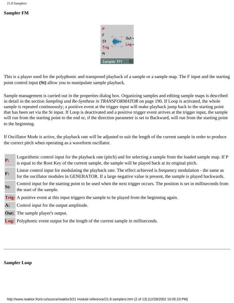
21.8 Samplers
Sampler FM
This is a player used for the polyphonic and transposed playback of a sample or a sample map. The F input and the starting point control input (St) allow you to manipulate sample playback.
Sample management is carried out in the properties dialog box. Organizing samples and editing sample maps is described in detail in the section Sampling und Re-Synthese in TRANSFORMATOR on page 190. If Loop is activated, the whole sample is repeated continuously; a positive event at the trigger input will make playback jump back to the starting point that has been set via the St input. If Loop is deactivated and a positive trigger event arrives at the trigger input, the sample will run from the starting point to the end or, if the direction parameter is set to Backward, will run from the starting point to the beginning.
If Oscillator Mode is active, the playback rate will be adjusted to suit the length of the current sample in order to produce the correct pitch when operating as a waveform oscillator.
P: Logarithmic control input for the playback rate (pitch) and for selecting a sample from the loaded sample map. If P is equal to the Root Key of the current sample, the sample will be played back at its original pitch.
F: Linear control input for modulating the playback rate. The effect achieved is frequency modulation - the same as for the oscillator modules in GENERATOR. If a large negative value is present, the sample is played backwards.
St: Control input for the starting point to be used when the next trigger occurs. The position is set in milliseconds from the start of the sample.
Trig: A positive event at this input triggers the sample to be played from the beginning again.
A: Control input for the output amplitude.
Out: The sample player's output.
Lng: Polyphonic event output for the length of the current sample in milliseconds.
Sampler Loop
http://www.reaktor.front.ru/source/reaktor3/21 module reference/21.8 samplers.htm (2 of 13) [12/28/2002 10:05:23 PM]

21.8 Samplers
This is a universal player for the polyphonic and transposed playback of mono or stereo samples, sample maps and WaveSets.
Sample management is carried out in the properties dialog box. Organizing samples and editing sample maps is described in detail in the section Sampling und Re-Synthese in TRANSFORMATOR on page 190. After a positive Gate event, sample playback starts from the starting point (configurable via the St input). If Loop is deactivated, the sample will run once from the starting point to the end or, if the direction parameter is set to Backward, will run from the starting point to the beginning. If Loop is activated, the sample will be continuously repeated within the loop range as soon as playback enters this range. The loop range is preset using data from the sound file from which the sample was loaded. If the sound file does not contain any loop data, the beginning of the sample is taken to be the beginning of the loop and the sample length is taken as the loop length. The loop data from the sound file are the default settings. These defaults are always used if the Loop Start (LS) or Loop Length (LL) inputs are not connected to other modules.
If the Loop in Release option is deactivated, loop playback will fade or fade out completely upon a Gate event occurring; depending on the direction set, the sample will run to its beginning or end and will then fade out. If the Loop in Release option is activated or if loop playback is switched off, the Gate events will only have a slight effect or none at all.
If the No Stereo option is activated (you can set this in the properties dialog box), stereo samples will be treated as mono samples, i.e. the same signal is sent to the L and R outputs. If this is the case. Sampler Loop only uses the left channel of stereo samples. This option has been made available because mono playback requires less processing capacity.
G: A positive event at this input starts output from the position that is set at the St input. If negative values are present at the input, loop playback is interrupted unless the Loop in Release option has been activated.
P:
Logarithmic control input for the playback rate (pitch). If P is equal to the Root Key of the current sample, the sample will be played back at its original pitch. Furthermore, if the Sel input is not connected, P determines the selection of samples from the sample map. In Oscillator Mode, the Sampler Loop functions as a digital oscillator. In the same way as in the oscillator modules in GENERATOR, P determines the fundamental pitch of the generated oscillation.
Sel: Control input for selecting a sample from the sample map. If this input is not connected, the values present at the P input are used instead.
F: Linear control input for modulating the playback rate. The effect achieved is frequency modulation - the same as for the oscillator modules in GENERATOR.
St: Control input for the starting point to be used when the next trigger occurs. The position is set in milliseconds from the start of the sample.
http://www.reaktor.front.ru/source/reaktor3/21 module reference/21.8 samplers.htm (3 of 13) [12/28/2002 10:05:23 PM]
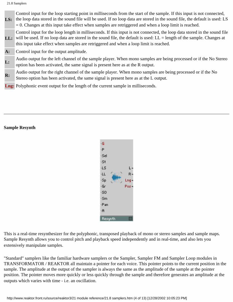
21.8 Samplers
LS: Control input for the loop starting point in milliseconds from the start of the sample. If this input is not connected, the loop data stored in the sound file will be used. If no loop data are stored in the sound file, the default is used: LS = 0. Changes at this input take effect when samples are retriggered and when a loop limit is reached.
LL: Control input for the loop length in milliseconds. If this input is not connected, the loop data stored in the sound file will be used. If no loop data are stored in the sound file, the default is used: LL = length of the sample. Changes at this input take effect when samples are retriggered and when a loop limit is reached.
A: Control input for the output amplitude.
L: Audio output for the left channel of the sample player. When mono samples are being processed or if the No Stereo option has been activated, the same signal is present here as at the R output.
R: Audio output for the right channel of the sample player. When mono samples are being processed or if the No Stereo option has been activated, the same signal is present here as at the L output.
Lng: Polyphonic event output for the length of the current sample in milliseconds.
Sample Resynth
This is a real-time resynthesizer for the polyphonic, transposed playback of mono or stereo samples and sample maps. Sample Resynth allows you to control pitch and playback speed independently and in real-time, and also lets you extensively manipulate samples.
"Standard" samplers like the familiar hardware samplers or the Sampler, Sampler FM and Sampler Loop modules in TRANSFORMATOR / REAKTOR all maintain a pointer for each voice. This pointer points to the current position in the sample. The amplitude at the output of the sampler is always the same as the amplitude of the sample at the pointer position. The pointer moves more quickly or less quickly through the sample and therefore generates an amplitude at the outputs which varies with time - i.e. an oscillation.
http://www.reaktor.front.ru/source/reaktor3/21 module reference/21.8 samplers.htm (4 of 13) [12/28/2002 10:05:23 PM]

21.8 Samplers
The speed of the pointer movement determines the speed of the sample playback (e.g. the speed of a beat loop). At the same time it also determines the pitch that is heard: the more slowly the signal (which has been recorded in the sample) is sampled, the longer the periods of the oscillations occurring at the output are - the pitch therefore decreases. If the pointer stops moving, the output amplitude stops changing. No audible signal is produced.
In the same way as a conventional sampler. Sample Resynth uses a pointer at the current sample position. However, the signal at the outputs is not simply the sample amplitude occurring at the pointer position. What actually happens is that the output signal is generated by a synthesizer inside the module. This synthesizer resynthesizes the signal at the pointer position. The pitch of the signal generated by this synthesizer is independent of the pointer's speed. Even if the pointer is not moving at all, the synthesizer continues to produce a sound. While the pitch of the output signal is determined, as is usual, over the P input, the Sp input determines the pointer speed.
Of course, the slowed down or "frozen" signal does not always correspond to what you might have imagined it to be. What does a hammer hitting a nail sound like if its is slowed down to infinity? The resynthesis algorithm used by Sample Resynth is designed in such a way that a broad range of sounds can be processed in a (musically-speaking) sensible, subtle or drastic manner. The algorithm can be adjusted by configuring the G (Granularity) and Sm (Smoothness) parameters. This means that you can manually adjust it to suit the sample and to produce drastic, strange sound effects. In the properties dialog box you can activate the Signal-informed Granulation option separately for each sample in a sample map. If this option is switched on, the resynthesize algorithm in Resynth takes information on the sample into account. This information was collected during the ana-lysis that was carried out when the sample was loaded for the first time What this means is that the algorithm reacts to the characteristics of the audio material If this option is deactivated, the results produced are generally quite "electronic"
Sample management is carried out in the properties dialog box Organizing samples and editing sample maps is described in detail in the section Sampling und Re-Synthese in TRANSFORMATOR on page 190 After a positive Gate event, sample playback starts from the starting point (configurable via the St input) If Loop is deactivated, the sample will run once from the starting point to the end or, if the direction parameter is set to Backward, will run from the starting point to the beginning If Loop is activated, the sample will be continuously repeated within the loop range as soon as playback enters this range The loop range is preset using data from the sound file from which the sample was loaded If the sound file does not contain any loop data, the beginning of the sample is taken to be the beginning of the loop and the sample length is taken as the loop length The loop data from the sound file are default settings These defaults are always used if the Loop Start (LS) or Loop Length (LL) inputs are not connected to other modules
If the Loop in Release option is deactivated, loop playback will fade or fade out completely upon a Gate event occurring Depending on the direction set, the sample will run to its beginning or end and will then fade out If the Loop in Release option is activated or if loop playback is switched off, the Gate events will only have a slight effect or none at all
If the No Stereo option is activated (you can set this in the properties dialog box), stereo samples will be treated as mono samples, i e the same signal is sent to the L and R outputs In this case, Resynth uses only the left channel of stereo samples This option has been made available because mono playback requires less processing capacity
All of the Resynth's inputs, except Gate, are designed as audio inputs The values at these inputs are applied when samples are (re-)tnggered (i e during positive Gate events) Changes to values during sample playback take effect in the Granularity interval (configured at the Gr input)
http://www.reaktor.front.ru/source/reaktor3/21 module reference/21.8 samplers.htm (5 of 13) [12/28/2002 10:05:23 PM]

21.8 Samplers
G: A positive event at this input begins output from the position that is set at the St input If negative values are present, loop playback is interrupted unless the Loop in Release option has been activated
P: Logarithmic audio control input for the playback rate (pitch) If P is equal to the Root Key of the current sample, the sample will by played back at its original pitch Furthermore, if the Sel input is not connected, P also determines the selection of samples from the sample map
Sel: Audio control input for selecting a sample from the sample map If this input is not connected, the values present at the P input are used instead
St: Audio control input for the starting point to be used when the next trigger occurs The position is set in milliseconds from the start of the sample
LS: Audio control input for the loop starting point in milliseconds from the start of the sample If this input is not connected, the loop data stored in the sound file will be used If no loop data are stored in the sound file, the default is used LS = 0
LL:
Audio control input for the loop length in milliseconds If this input is not connected, the loop data stored in the sound file will be used If no loop data are stored in the sound file, the default is used LL= length of the sample If LL = 0, the movement within the sample stops when the loop starting point is reached, the sound is frozen at this point
Sp:
Audio control input for pitch-independent output speed Values that are present at the input are interpreted as a factor When Sp = 1, playback occurs at the original speed, Sp = 2 corresponds to double the speed, and Sp = 0 means stop If this input is not connected, the transposed original speed is taken as the default so that - as in conventional samplers - the speed reduces as pitch decreases
Gr: Audio control input for the granularity of the resynthesis process in milliseconds This parameter determines the size of the sound particles used for resynthesis If the Signal-informed Granulation option is active, the values at the input will be used as the default, the values that are actually used are adjusted to suit the material
SO: Audio control input for modulation of the sample position (Sample Offset) in milliseconds. This input is used in order to modulate the position in the sample independent of pitch, e.g. via a noise generator.
Sm: Audio control input for the Smoothness of the resynthesis process. The sound particles are adjusted using this. Small values generally lead to a rougher resulting sound.
Pan: Audio control input for the position in the stereo field (-1 = Left, 0 = Center, 1 = Right).
A: Audio control input for the output amplitude.
L: Audio output for the left channel of the resynthesizer.
R: Audio output for the right channel of the resynthesizer.
Lng: Polyphonic event output for the length of the current sample in milliseconds.
Pos: Polyphonic event output for the current position in the sample in milliseconds. Events are generated at time intervals corresponding to the set Granularity (Gr).
Sample Pitch Former
http://www.reaktor.front.ru/source/reaktor3/21 module reference/21.8 samplers.htm (6 of 13) [12/28/2002 10:05:23 PM]

21.8 Samplers
This is a real-time resynthesizer for the polyphonic playback of mono or stereo samples and sample maps or WaveSets. Sample Pitch Former is a WaveSet synthesizer in which not only WaveSets can be loaded but also any samples you like. Sample Pitch Former removes the pitch development from a sample and gives the sample any new pitch you wish. Besides independent real-time control over the playback speed, Sample Pitch Former also allows you to carry out a spectral transposition, i.e. a pitch-independent transposition of the timbre.
"Standard" samplers like the familiar hardware samplers or the Sampler, Sampler FM and Sampler Loop modules in TRANSFORMATOR / REAKTOR all maintain a pointer for each voice. This pointer points to the current position in the sample. The amplitude at the output of the sampler is always the same as the amplitude of the sample at the pointer position. The pointer moves more quickly or less quickly through the sample and therefore generates an amplitude at the outputs which varies with time - i.e. an oscillation.
The speed of the pointer movement determines the speed of the sample playback. At the same time it also determines the pitch that is heard: the more slowly the signal (that has been recorded in the sample) is sampled, the longer are the periods of the oscillations occurring at the output - the pitch therefore decreases. If the pointer stops moving, the output amplitude stops changing. No audible signal is produced.
In the same way as a conventional sampler, Sample Pitch Former uses a pointer at the current sample position. However, the signal at the outputs is not simply the sample amplitude occurring at the pointer position. What actually happens is that the output signal is generated by a synthesizer inside the module. This synthesizer resynthesizes the signal at the pointer position. The pitch of the signal generated by this synthesizer is independent of the pointer's speed. Even if the pointer is not moving at all, the synthesizer continues to produce a sound. While the pitch of the output signal is determined, as is usual, via the P input, the Sp input determines the pointer speed.
While conventional samplers and the Sample Resynth module in TRANSFORMATOR / REAKTOR achieve a relative pitch change by transposing a sample, Sample Pitch Former forces any absolute and definite pitch that you wish onto a sample. Sample Pitch Former can therefore be used like a GENERATOR oscillator. Depending on the type of processed sound material and the settings used, the result can sound "electronically" altered to a greater or lesser degree. Sample Pitch Former will also generate signals with a certain pitch if the processed sample has no unique pitch of its own (e.g. recordings of cymbals or gongs). Sample Pitch Former produces fewer sound alterations the more restricted the fundamental pitch of the processed material is to be defined, and the less the original pitch deviates from the generated
http://www.reaktor.front.ru/source/reaktor3/21 module reference/21.8 samplers.htm (7 of 13) [12/28/2002 10:05:23 PM]

21.8 Samplers
pitch.
In conventional samplers and in the Sample Resynth module in TRANSFORMATOR / REAKTOR, the transposing of the fundamental pitch goes hand in hand with the transposing of all the spectral components. This is often considered a limitation since the transposition also affects certain spectral components which the listener would not expect to hear changed. The "Mickey Mouse effect" that occurs when speech recordings are detuned can be traced back to the transposition of the formants whose position for a "real" human speaker would be largely independent of the fundamental pitch. Within certain limits, Sample Pitch Former decouples pitch and formant position from one another. The formant position can be shifted independent of pitch via the formant shift input (FS). Since the human ear uses all the spectral components to identify the fundamental pitch, you can manipulate this parameter to create interesting substitutions of fundamental pitch and timbre, especially at very low pitches. Similar sound effects are often created by synthesizer experts using oscillator synchronization.
Sample management is carried out in the properties dialog box. Organizing samples and editing sample maps is described in detail in the section Sampling und Re-Synthese in TRANSFORMATOR on page 190. After a positive Gate event, sample playback starts from the starting point (configurable via the St input). If Loop is deactivated, the sample will run once from the starting point to the end or, if the direction parameter is set to Backward, will run from the starting point to the beginning. If Loop is activated, the sample will be continuously repeated within the loop range as soon as playback enters this range. The loop range is preset using data from the sound file from which the sample was loaded. If the sound file does not contain any loop data, the beginning of the sample is taken to be the beginning of the loop and the sample length is taken as the loop length. The loop data from the sound file are default settings. These defaults are always used if the Loop Start (LS) or Loop Length (LL) inputs are not connected to other modules.
If the Loop in Release option is deactivated, loop playback will fade or fade out completely upon a Gate event occurring. Depending on the direction set, the sample will run to its beginning or end and will then fade out. If the Loop in Release option is activated or if loop playback is switched off. Gate events that are smaller than or equal to zero have no effect.
If the NO Stereo option is activated (you can set this in the properties dialog box), stereo samples will be treated as mono samples, i.e. the same signal is sent to the L and R outputs. In this case, Sample Pitch Former uses only the left channel of stereo samples. This option has been made available because mono playback requires less processing capacity.
All of Sample Pitch Former's inputs, except Gate, are designed as audio inputs. The values at the inputs are applied when samples are (re-) triggered (i.e. during positive Gate events). During sample playback, changes to values take effect at intervals of the fundamental pitch period (you can set this via the P input).
G: A positive event at this input starts output from the position, that is set at the St input. If negative values are present, loop playback is interrupted unless the Loop in Release option has been activated.
P: Logarithmic audio control input for the playback rate (pitch). Furthermore, if the Sel input is not connected, P also determines the selection of samples from the sample map.
Sel: Audio control input for selecting a sample from the sample map. If this input is not connected, the values present at the P input are used instead.
St: Audio control input for the starting point to be used when the next trigger occurs. The position is set in milliseconds from the start of the sample.
http://www.reaktor.front.ru/source/reaktor3/21 module reference/21.8 samplers.htm (8 of 13) [12/28/2002 10:05:24 PM]

21.8 Samplers
LS: Audio control input for the loop starting point in milliseconds from the start of the sample If this input is not connected, the loop data stored in the sound file will be used If no loop data are stored in the sound file, the default is used LS = 0
LL:
Audio control input for the loop length in milliseconds If this input is not connected, the loop data stored in the sound file will be used If no loop data are stored in the sound file, the default is used LL = length of the sample If LL = 0, the movement within the sample stops when the loop starting point is reached, the sound is frozen at this point
Sp: Audio control input for pitch-independent output speed Values that are present at the input are interpreted as a factor when Sp = 1, playback occurs at the original speed, Sp - 2 corresponds to double the speed, and Sp = 0 means stop If this input is not connected, the value 1 is taken as the default
FS: Audio control input for pitch-independent transposing of the formant position in semi-tones
SO: Audio control input for modulation of the sample position (Sample Offset) in milliseconds This input is used to modulate the position in the sample independent of pitch, e. g. via a noise generator
Sm: Audio control input for the Smoothness of the resynthesis process The sound particles are adjusted using this Small values generally lead to a rougher resulting sound
Pan: Audio control input for the position in the stereo field (-1 = Left, 0 = Center, 1 = Right)
A: Audio control input for the output amplitude
L: Audio output for the left channel of the resynthesizer
R: Audio output for the right channel of the resynthesizer
Lng: Polyphonic event output for the length of the current sample in milliseconds
Pos: Polyphonic event output for the current position in the sample in milliseconds Events at this input are generated at time intervals corresponding to the current fundamental pitch period
Beat Loop
http://www.reaktor.front.ru/source/reaktor3/21 module reference/21.8 samplers.htm (9 of 13) [12/28/2002 10:05:24 PM]

21.8 Samplers
This is a real-time resynthesizer for the synchronized playback of beat-loop samples The transposing of beat-loops can be set via the P input independent of playback speed Beat Loop synchronizes itself to a 96th note clock source (24 ppq) that is connected to the C input or, if the C input is not connected, it can sync with the global TRANSFORMATOR / REAKTOR clock Therefore, by default all Beat Loops in TRANSFORMATOR / REAKTOR run in sync with one another independent of the sample's internal speed Furthermore, Beat Loop also allows you to easily link internal TRANSFORMATOR / REAKTOR sequencer modules and MIDI clocks to rhythmic sample material
Sample management is carried out in the properties dialog box Organizing samples and editing sample maps is described in detail in the section Sampling und Re Synthese in TRANSFORMATOR on page 190 Beat Loop requires samples that have been cut exactly, and which contain 2, 4, 8, 16, or 32, etc. beats The speed of the beat loops used should be between 87 and 174 BPM If the samples being used fulfill these conditions, Beat Loop can output them in good quality even if the playback speed is changed By activating the sample-related Pitched Sound option (accessible in the properties dialog box), possible pitch falsification of basslines (and similar) can be avoided However, in doing so you will have to accept a deterioration in rhythmic precision
The loop range of the sample is configured using the Loop Start (LS) and Loop Length (LL) inputs. If LS and LL are not connected, the whole sample will be played back as a loop. Using positive Rst events, sample playback will be continued from the starting point (you can set this via the St input).
If the No Stereo option is activated (you can set this in the properties dialog box), stereo samples will be treated as mono samples, i.e. the same signal is sent to the L and R outputs. In this case, Beat Loop uses only the left channel of stereo samples. This option has been made available because mono playback requires less processing capacity.
All of Beat Loop's inputs, except C and Rst, are designed as audio inputs. During sample playback, changes to values take effect at intervals of sixteenths of a note value.
C: A positive event at this input switches the Beat Loop module by one 96th note value further. If this input is not connected, the module synchronizes itself with the global TRANSFORMATOR / REAKTOR clock.
Rst: A positive event at this input resets playback to the position set at the St input.
P: Logarithmic audio control input for the playback rate (pitch). Furthermore, if the Sel input is not connected, P determines the selection of samples from the sample map.
Sel: Audio control input for selecting a sample from the sample map. If this input is not connected, the values present at the P input are used instead.
St: Audio control input for the starting point to be used when the next trigger occurs. The position is set in sixteenths of a note value from the start of the sample.
LS: Audio control input for the loop starting point in sixteenths of a note value from the start of the sample. If this input is not connected, the default is used: LS = 0.
LL: Audio control input for the loop length in sixteenths of a note value. If this input is not connected, the default is used: LL = length of the sample.
SO: Audio control input for modulation of the sample position (Sample Offset) in sixteenths of a note value. This input is used to reach steps in the sample which, for instance, can be controlled by a sequencer module.
Sm: Audio control input for the Smoothness of the resynthesis process. The sound particles are adjusted using this. Very small values generally lead to a "cracking" sound every sixteenth interval.
http://www.reaktor.front.ru/source/reaktor3/21 module reference/21.8 samplers.htm (10 of 13) [12/28/2002 10:05:24 PM]

21.8 Samplers
Pan: Audio control input for the position in the stereo field (-1 = Left, 0 = Center, 1 = Right).
A: Audio control input for the output amplitude.
L: Audio output for the left channel of the resynthesizer.
R: Audio output for the right channel of the resynthesizer.
Len: Polyphonic event output for the length of the current sample in milliseconds.
L16: Polyphonic event output for the length of the current sample in sixteenths of a note value.
P16: Polyphonic event output for the current position in the sample in sixteenths of a note value.
Ct16: Polyphonic event output for counting the sixteenths of a note value that have passed since the start / reset.
Sample Lookup
® This module makes samples available as function value look-up tables. A position within the sample in milliseconds is set via the Pos input. The value of the sample at this point is sent to the outputs.
You can load sound files using the Load Sound... entry in the context menu.
The properties dialog box allows you to select one of three levels of quality that is to be used for interpolation during transposed sample playback (Poor, Good, Excellent). If set to Poor, the sample values are not interpolated during output. Higher playback quality is achieved at the expense of processing capacity.
Pos: Audio input for the position in the sample in milliseconds.
A: Audio input for amplitude modulation.
L: Audio output for the left channel of the sample. When processing mono samples, the same signal is output here as is sent to the R output.
R: Audio output for the right channel of the sample. When processing mono samples, the same signal is output here as is sent to the L output.
Lng: Polyphonic event output for the length of the current sample in milliseconds.
http://www.reaktor.front.ru/source/reaktor3/21 module reference/21.8 samplers.htm (11 of 13) [12/28/2002 10:05:24 PM]

21.8 Samplers
Grain Cloud
Stereo-multi-sample granular-synthesizer with independent control over pitch P, pitch-slide PS, sample selection Sel, sample-position Pos and length Len of each grain. The envelope of each grain can be controlled with attack Att and decay Dec.
For each grain the delta time to the start of the next grain can be set with dt. The maximum number of simultaneous grains can be set in the Properties.
There are several jitter-inputs which set a range for the respective input. Double-click on the module to open the sample-map-window.
Trig: Event input for the Gate signal. (G) > 0 starts immediately next gain.
P: Audio input for logarithmic pitch control (in semitones). The pitch is independent of the speed traversal. The sample plays at the original pitch when P=Root key. Typ. range: [0...127], De-fault: 60.
D/F: Audio input for direction control if P is connected. Otherwise it is a frequency controls. The sample plays at the original pitch when F=1, in reverse direction when F=-1. Typ. range: [-4...4], Default: 1.
PJ: Audio input for pitch jitter control (in semitones). Typ. range: [0...3].
PS: Audio input for logarithmic pitch shift control of current grain in semitones. Typ. range: [-3...3].
Sel: Audio input for multi-sample selection (in semitones). When unconnected, the values at the (P) input are used. Typ. range: [0...127].
http://www.reaktor.front.ru/source/reaktor3/21 module reference/21.8 samplers.htm (12 of 13) [12/28/2002 10:05:24 PM]

21.8 Samplers
Pos: Audio input for setting the sound file poition in ms. Range [0...<length of sample in ms>].
PsJ: Audio input for sound file position jitter control in ms. Typ. range: [0...<length of sample in ms>].
Len: Audio input for setting the grain length in ms. Typ range: [10...100]. Default: 20ms.
LnJ: Audio input for grain length jittercontrol in ms. Typ range: [10...100]. Default: 0 ms.
Att: Audio input for setting the attack time. Range: [0...1]. Default: 0.2.
Dec: Audio input for setting the decay time. Range: [0...1]. Default: 0.2.
dt: Audio input for setting the delta time before starting the next grain in ms. Typ range: [5...100]. Default: 20.
dtJ: Audio input for delta time jitter control in ms. Typ range: [10...100]. Default: 20ms.
Pan: Audio input for setting the position in the stereo field. Range: [-l(Left)...l(Right)].
PnJ: Audio input for pan jitter control. Range: [0...1].
A: Audio input for amplitude control. Typ range: [0...1]. Default: 1.
L: Polyphonic left channel audio output. Typ range: [-1...1].
R: Polyphonic right channel audio output. Typ range: [-1...1].
Lng: Event output for the length of samples in ms. Typ range: [0...<length of samples in ms>].
GTr: Event output for grain trigger. Outputs 1 when a new grain starts, 0 when it stops.
http://www.reaktor.front.ru/source/reaktor3/21 module reference/21.8 samplers.htm (13 of 13) [12/28/2002 10:05:24 PM]

21.9 Sequencer
Click here to show toolbars of the Web Online Help System: show toolbars
21.9 Sequencer
Start/Stop
Source for start and stop events for the synchronization with external MIDI devices or the internal master clock.
The output of the Start/Stop module is a monophonic gate signal. Its value can be set with Output Value in the properties. The signal jumps to the set value when the start button in the toolbar is pressed or when a MIDI Start event is received, as appropriate. The signal jumps back to zero when the stop button is pressed or when a MIDI Stop event is received.
The module is typically connected to the reset input of sequencers and event dividers which are synchronized with the MIDI Clock to force a synchronous start.
Sync Clock
Source for a clock signal which is derived from an external MIDI Clock or the internal master clock.
The output of the Synch Clock module is a monophonic gate signal. The value can be set with Output Value in the properties. At each beat, the gate jumps to the respective value and back to zero after a certain time interval. The module is activated and deactivated by start-stop events.
http://www.reaktor.front.ru/source/reaktor3/21 module reference/21.9 sequencer.htm (1 of 6) [12/28/2002 10:05:27 PM]

21.9 Sequencer
The rate of the clock signal (quarter, eighth, sixteenth notes, etc.) can be adjusted in properties as Rate.
The duration of the gate signal (eighth, sixteenth note, etc.) can be adjusted in properties as Duration.
1/96 Clock
Source of a clock signal which corresponds to the external MIDI Clock or the internal master clock.
For each 96th note an event is sent at the output. The value can be set as Output Value in the properties.
In contrast to the Sync Clock source, the events of the 1/96 Clock have to be processed by an Event Freq. Divider (see page 344). This has the advantage that you can experiment with arbitrary division factors.
Song Pos
Source for the Song Position, counted in 96th notes from the song start Typically connect this to input (A) of the Modulo module and a Constant of 6 to the (B) input, to get a 16th note count at the (Div) output.
96: Event output for the integer count of 96th notes (that's 24 ppq). Use the Modulo module to get counts of other denominations.
96a: Audio output for the sample-accurate fractional song position measured in 96th notes (24 per quarter note).
http://www.reaktor.front.ru/source/reaktor3/21 module reference/21.9 sequencer.htm (2 of 6) [12/28/2002 10:05:27 PM]

21.9 Sequencer
Clock
Free running clock source. An internal oscillator (monophonic) produces regular clock on/off pulses in the form of events, e.g. for driving a sequencer. The value of the on-events can be set in the module properties.
F: Event input for control of clock frequency in Hz. For control of Tempo in BPM, compute the value in Hz as follows: clocks-per-beat x BPM/60. So, for 16th note clocks at 4 beats to the bar (that is four 16ths per beat), you get F = 4/60 x BPM or 0.0667 x BPM.
W: Event input for control of pulse width, i.e. the ratio of the duration of the on-period to the off-period. Range of values is -1 to 1. Symmetric waveform (equal duration on and off) at W = 0; Lo:Hi = (1+W)/(1-W).
Snc: Event input for synchronization of the waveform. A positive event synchronizes the clock source.
Out: Event output for the clock signal, alternating between on-value and zero.
A: input for controlling the amplitude of the clock signal. You must connect something here, otherwise only zero-value events will be produced. Typ. Value: 1
Sequencer
http://www.reaktor.front.ru/source/reaktor3/21 module reference/21.9 sequencer.htm (3 of 6) [12/28/2002 10:05:27 PM]

21.9 Sequencer
6-Step
Sequencer with 6 steps. The output value for each step (e.g. to control oscillator pitch) can be set independently. In addition a gate signal is output with the amplitude given by the current value of the gate amplitude input at the time the step advances.
C: Audio input for clock control. A positive zero crossing switches to the next step.Typically you would connect a Pulse Oscillator or MIDI Sync module here.
Rst: Audio input for a reset signal. A positive zero crossing puts the sequencer back to the first step. Typically you would connect a button or MIDI Start module here.
GA: Audio input for controlling the amplitude of the gate output. When the value is zero or the input is not connected, no signal appears on the gate output.
S1: Audio input for controlling the value of the first step.
S2: Audio input for controlling the value of the second step.
S3: Audio input for controlling the value of the third step.
S4: Audio input for controlling the value of the fourth step.
http://www.reaktor.front.ru/source/reaktor3/21 module reference/21.9 sequencer.htm (4 of 6) [12/28/2002 10:05:27 PM]

21.9 Sequencer
S5: Audio input for controlling the value of the fifth step.
S6: Audio input for controlling the value of the sixth step.
Out: Event output for the sequencer step signal.
G: Event output for the gate signal.
Stp: Event output for the current step number.
8-Step Like 6-Step Sequencer but with 8 steps.
12-Step Like 6-Step Sequencer but with 12 steps.
16-Step Like 6-Step Sequencer but with 16 steps.
Select 16
http://www.reaktor.front.ru/source/reaktor3/21 module reference/21.9 sequencer.htm (5 of 6) [12/28/2002 10:05:27 PM]

21.9 Sequencer
Value Selector, useful as a sequencer. An event at Pos addresses with its value one of the 16 inputs and the current value at this input is forwarded to Out.
If the Pos input is driven by a signal which is incremented stepwise, the output Out provides a sequence of the values at the inputs 0...15. The values at the Pos input are folded into the number range [0 ... (Len - 1)] to allow a variable sequence length Len.
The Pos input can also be driven by a control element, a Beat Loop module, a random event source, or by the master clock.
Pos: Input for controlling the selection. Each event at this input results in an event at the outputs. To run Select 16 as a sequencer, the position is set to the number of 16th notes that have passed since start or reset.
Len: Input to set the sequence length. Range: [ 1 ... 16 ].
0-15: Audio input for controlling the value of the appropriate step.
Stp: Current sequence step number. The number at this output is calculated as Pos modulo Len. Range: [ 0 ... <sequence length> ].
Bar: Current bar number. The number at this output is calculated as Integer (Pos / Len).
Out: Current sequence step output value.
http://www.reaktor.front.ru/source/reaktor3/21 module reference/21.9 sequencer.htm (6 of 6) [12/28/2002 10:05:27 PM]

21.10 LFO, Envelope
Click here to show toolbars of the Web Online Help System: show toolbars
21.10 LFO, Envelope
LFO
Low Frequency Oscillator with Pulse, Triangle and Parabol Wave outputs. It is typically used as a source for modulation signals (for vibrato, tremolo etc.). The output signal is a stream of events at the Control Rate selected in the Settings menu.
Since the LFO operates at the Control Rate, it is much more CPU efficient than an audio oscillator which could do the same job.
F: Audio input for control of the oscillator frequency in Hz. For control with Tempo in BPM, you can compute the required value in Hz as follows: F = oscillations-per-beat x BPM/60. So, for example, for 3 oscillations per bar at 4 beats to the bar (that is % oscillations per beat), you get F = (%)/60 x BPM or 0.0125 x BPM.
A: Input for controlling the amplitude. The output signal moves between +A and -A.
W: Event input for control of pulse width, i.e. the ratio of the duration of the on-period to the off-period for the pulse output, and appropriate warping of the other waveforms. Range of values is -1 to 1. Symmetric waveforms at W = 0.
Snc: Event input for synchronization of the LFO waveform. A positive event synchronizes the oscillator, resetting it to the phase given by the Ph input.
Ph: Input for specifying the phase (position in the waveform) to which the oscillator is reset when synchronization occurs. Ph = 0: Phase = 0 deg (middle of rising slope), Ph - 0.5: Phase = 180 deg (middle of falling slope), Ph = 1: Phase = 360 deg (same as 0 deg).
Sin: Event output for the sine waveshape signal.
Tri: Event output for the triangle waveshape signal.
Pls: Event output for the pulse waveshape signal.
http://www.reaktor.front.ru/source/reaktor3/21 module reference/21.10 lfo, envelope.htm (1 of 12) [12/28/2002 10:05:34 PM]

21.10 LFO, Envelope
Slow Random
Low Frequency Oscillator which produces a random step waveform.
F: Control input for the step frequency in Hz.
A: Control input for the amplitude. The output value is somewhere in the range -A to +A.
Out: Event output for the random signal.
H-Env
Envelope generator with hold characteristic. When the envelope is triggered the output value jumps to the current value of the amplitude input and stays there until the hold time has passed, after which the output jumps back to zero. The envelope can be triggered at any time, including retriggering during the hold time.
T: Audio input for triggering the envelope on a rising edge (value leaves zero in positive direction).
A: Audio input for the output value during the hold time. The input is sampled at the triggering instant after which the value is held at the output.
H: Logarithmic event input for controlling the hold time. 0 = 1 ms, 20 = 10 ms, 40 = 100 ms (i.e. in dB1ms).
Out: Audio output for the envelope signal.
http://www.reaktor.front.ru/source/reaktor3/21 module reference/21.10 lfo, envelope.htm (2 of 12) [12/28/2002 10:05:34 PM]

21.10 LFO, Envelope
HR - Env
Envelope generator with hold-release characteristic. When the envelope is triggered the output value jumps to the current value of the amplitude input and stays there until the hold time has passed, after which the output decays exponentially with the release time back to zero.
T: Audio input for triggering the envelope on a rising edge (value leaves zero in positive direction).
A: Audio input for the output value during the hold time. The input is sampled at the triggering instant after which the value is held at the output.
H: Logarithmic event input for controlling the hold time. 0 = 1 ms, 20 = 10 ms, 40 = 100 ms (i.e. in dB1ms).
R: Logarithmic event input for controlling the release time. 0 = 1 ms, 20 = 10 ms, 40 = 100 ms (i.e. in dB1ms).
Out: Audio output for the envelope signal.
D-Env
Envelope generator with decay characteristic. When the envelope is triggered the output value jumps to the current value of the amplitude input, after which the output decays exponentially with the decay time back to zero.
T: Audio input for triggering the envelope on a rising edge (value leaves zero in positive direction).
A: Audio input for the initial output value. The input is sampled at the triggering instant.
D: Logarithmic event input for controlling the decay time. 0 = I ms, 20 = 10 ms, 40 = 100 ms (i.e. in dB1ms).
http://www.reaktor.front.ru/source/reaktor3/21 module reference/21.10 lfo, envelope.htm (3 of 12) [12/28/2002 10:05:34 PM]

21.10 LFO, Envelope
Out: Audio output for the envelope signal.
DR - Env
Envelope generator with decay-release characteristic. When. the envelope is triggered with a gate event the output value jumps to the amplitude value of the gate signal, after which the output decays exponentially with the decay time back to zero. A gate event with amplitude zero (at note off) sets the decaying time to the release time value which is normally set to be shorter.
G: Event input for the gate signal that triggers the envelope. The amplitude of the gate signal determines the initial output value-
D: Logarithmic event input for controlling the decay time. 0=1 ms, 20 - 10 ms, 40 - 100 ms (i.e. in dB1ms).
R: Logarithmic event input for controlling the release time. 0 = 1 ms, 20 = 10 ms, 40 = 100 ms (i.e. in dB1ms).
Out: Audio output for the envelope signal.
DSR - Env
Envelope generator with decay-suslain-release characteristic. When the envelope is triggered with a gate event the output value jumps to the amplitude value of the gate signal, after which the output decays exponentially with the decay time to the sustain level (multiplied by the amplitude). After a gate event with amplitude zero (at note off) the output decays exponentially with the release time back to zero.
http://www.reaktor.front.ru/source/reaktor3/21 module reference/21.10 lfo, envelope.htm (4 of 12) [12/28/2002 10:05:34 PM]

21.10 LFO, Envelope
G: Event input for the gate signal that triggers the envelope. The amplitude of the gate signal determines the initial output value.
D: Logarithmic event input for controlling the decay time. 0 = 1 ms, 20 = 10 ms, 40 = 100 ms (i.e. in dB1ms).
S: Event input for controlling the sustain level. Typical range of values is: 0 (decay to zero) to 1 (hold at initial level), but sustain can be greater than 1 or even less than 0.
R: Logarithmic event input for controlling the release time. 0 = 1 ms, 20 = 10 ms, 40 = 100 ms (i.e. in dB1ms).
Out: Audio output for the envelope signal.
DBDR- Env
Envelope generator with decay-breakpoint-release characteristic. When the envelope is triggered with a gate event the output value jumps to the amplitude value of the gate signal, after which the output decays exponentially with the decay-1 time until it reaches the breakpoint level (multiplied by the amplitude). Next it continues decaying exponentially with the decay-2 time back to zero. A gate event with amplitude zero (at note off) sets the decaying time to the release time value which is normally set to be shorter.
G: Event input for the gate signal that triggers the envelope. The amplitude of the gate signal determines the initial output value.
D1: Logarithmic event input for controlling the first decay time. 0 = 1 ms, 20 = 10 ms, 40 = 100 ms (i.e. in dB1ms).
B: Event input for controlling the breakpoint level. Range of values: 0 (never use decay-2 time) to 1 (immediately use decay-2 time).
D2: Logarithmic event input for controlling the second decay time. 0 = 1 ms, 20 - 10 ms, 40 = 100 ms (i.e. in dB1ms).
R: Logarithmic event input for controlling the release time. 0 = 1 ms, 20 = 10 ms, 40 = 100 ms (i.e. in dB1ms).
Out: Audio output for the envelope signal.
http://www.reaktor.front.ru/source/reaktor3/21 module reference/21.10 lfo, envelope.htm (5 of 12) [12/28/2002 10:05:34 PM]

21.10 LFO, Envelope
AD - Env
Attack-Decay envelope, triggered by the positive slope of the T signal. The decay starts immediately, when the attack time is over.
T: Input for the trigger signal. A positive slope starts the envelope.
A: Control input for the output amplitude.
A: Control input for the attack time of the envelope. 0 = 1 ms, 20 = 10 ms, 40 = 100 ms (i.e. in dB1ms).
D: Control input for the decay time of the envelope. 0 = 1 ms, 20 = 10 ms, 40 = 100 ms (i.e. in dB1ms).
Out: Output for the envelope signal.
AR - Env
Envelope generator with attack-release characteristic. When the envelope is triggered with a gate event the output value rises during the attack time with a linear slope to the amplitude value of the gate signal. The output is then held at the maximum level until a gate event with amplitude zero (at note off) arrives, after which the output decays exponentially with the release time back to zero.
G: Event input for the gate signal that triggers the envelope. The am-plitude of the gate signal determines the maximum output value.
A: Logarithmic event input for controlling the attack time. 0 = 1 ms, 20= 10ms, 40 100ms (i.e. in dB1ms).
R: Logarithmic event input for controlling the release time. 0 = 1 ms, 20 = 10 ms, 40 = 100 ms (i.e. in dB1ms).
Out: Audio output for the envelope signal.
http://www.reaktor.front.ru/source/reaktor3/21 module reference/21.10 lfo, envelope.htm (6 of 12) [12/28/2002 10:05:34 PM]

21.10 LFO, Envelope
ADSR - Env
Envelope generator with the classic attack-decay-sustain-release characteristic. When the envelope is triggered with a gate event the output value rises during the attack time with a linear slope to the amplitude value of the gate signal, after which it decays exponentially with the decay time to the sustain level (multiplied by the amplitude). The output is held at the sustain level until a gate event with amplitude zero (at note off) arrives, after which the output decays exponentially with the release time back to zero.
G: Event input for the gate signal that triggers the envelope. The amplitude of the gate signal determines the maximum output value.
A: Logarithmic event input for controlling the attack time. 0 = 1 ms, 20 = 10 ms, 40 = 100 ms (i.e. in dB1ms).
D: Logarithmic event input for controlling the decay time. 0 = 1 ms, 20 = 10 ms, 40 = 100 ms (i.e. in dB1ms).
S: Event input for controlling the sustain level. Typical range of values is: 0 (decay to zero) to 1 (hold at end of attack), but sustain can be greater than 1 or even less than 0.
R: Logarithmic event input for controlling the release time. 0 = 1 ms, 20 = 10 ms, 40 = 100 ms (i.e. in dB1ms).
Out: Audio output for the envelope signal.
ADBDR- Env
http://www.reaktor.front.ru/source/reaktor3/21 module reference/21.10 lfo, envelope.htm (7 of 12) [12/28/2002 10:05:34 PM]

21.10 LFO, Envelope
Envelope generator with attack-decay-breakpoint-decay-release characteristic. When the envelope is triggered with a gate event the output value rises during the attack time with a linear slope to the amplitude value of the gate signal, after which it decays exponentially with the decay-1 time until it reaches the breakpoint level (multiplied by the amplitude). Next it continues decaying exponentially with the decay-2 time back to zero. A gate event with amplitude zero (at note off) sets the decaying time to the release time value which is normally set to be shorter.
G: Event input for the gate signal that triggers the envelope. The amplitude of the gate signal determines the maximum output value.
A: Logarithmic event input for controlling the attack time. 0 = 1 ms, 20 = 10 ms, 40 = 100 ms (i.e. in dB1ms).
D1: Logarithmic event input for controlling the first decay time. 0 = 1 ms, 20 = 10 ms, 40 = 100 ms (i.e. in dB1ms).
B: Event input for controlling the breakpoint level. Range of values: 0 (never use decay=2 time) to 1 (immediately use decay=2 time).
D2: Logarithmic event input for controlling the second decay time. 0 = 1 ms, 20 = 10 ms, 40 = 100 ms (i.e. in dB1ms).
R: Logarithmic event input for controlling the release time. 0 = 1 ms, 20 = 10 ms, 40 = 100 ms (i.e. in dB1ms).
Out: Audio output for the envelope signal.
ADBDSR-Env
Envelope generator with attack-decay-breakpoint-decay-sustain-release characteristic. When the envelope is triggered with
http://www.reaktor.front.ru/source/reaktor3/21 module reference/21.10 lfo, envelope.htm (8 of 12) [12/28/2002 10:05:34 PM]

21.10 LFO, Envelope
a gate event the output value rises during the attack time with a linear slope to the amplitude value of the gate signal, after which it decays according to the first decay time with a linear slope to the breakpoint level. From there it continues with the second decay time to the sustain level (the levels are multiplied by the amplitude). The output is held at the sustain level until a gate event with amplitude zero (at note off) arrives, after which the output decays exponentially with the release time back to zero.
G: Event input for the gate signal that triggers the envelope. The amplitude of the gate signal determines the maximum output value.
A: Logarithmic event input for controlling the attack time. 0=1 ms, 20 = 10 ms, 40 = 100 ms (i.e. in dB1ms).
D1: Logarithmic event input for controlling the first decay time. 0 = 1 ms, 20 = 10 ms, 40 = 100 ms (i.e. in dB1ms).
B: Event input for controlling the break point level. Typical range of values is: 0 to 1.
D2: Logarithmic event input for controlling the second decay time. 0 = 1 ms, 20 = 10 ms, 40 = 100 ms (i.e. in dB1ms).
S: Event input for controlling the sustain level. Typical range of values is: 0 to 1.
R: Logarithmic event input for controlling the release time. 0 = 1 ms, 20 = 10 ms, 40 = 100 ms (i.e. in dB1ms).
Out: Audio output for the envelope signal.
4-Ramp
4-stage envelope generator with linear slopes. When the envelope is triggered with a gate event the output value rises to the first level, reaching it within the time set for the first stage. Then it continues to the second level within the time set for the second stage, and so on. The third level is the sustain level, at which the output is held until a gate event with amplitude zero (at note off) arrives, after which the output returns to zero within the last time-period.
G: Event input for the gate signal that triggers the envelope. The amplitude of the gate signal combines with all the level values to determine the actual levels reached.
T1: Logarithmic event input for controlling the time for the first stage. 0 = 1 ms, 20 = 10 ms, 40 = 100 ms (i.e. in dB1ms).
http://www.reaktor.front.ru/source/reaktor3/21 module reference/21.10 lfo, envelope.htm (9 of 12) [12/28/2002 10:05:34 PM]

21.10 LFO, Envelope
L1: Input for controlling the level which is reached at the end of the first stage.
T2: Logarithmic event input for controlling the time for the second stage. 0 = 1 ms, 20 = 10 ms, 40 = 100 ms (i.e. in dB1ms).
L2: Input for controlling the level which is reached at the end of the second stage.
T3: Logarithmic event input for controlling the time for the third stage. 0 = 1 ms, 20 = 10 ms, 40 = 100 ms (i.e. in dB1ms).
LS: Input for controlling the level which is reached at the end of the third stage. This is the sustain level.
TR: Logarithmic event input for controlling the time for the last stage which is the release. 0=1 ms, 20 = 10 ms, 40 = 100 ms (i.e.in dB1ms).
Stg:Event output for the envelope's current stage (1, 2 ...). After the end of the release stage and before a new trigger, the value is 0. With appropriate processing this value can be used to chain other envelopes, or for the envelope to retrigger itself.
Out: Audio output for the envelope signal.
5-Ramp
5-stage envelope generator with linear slopes. When the envelope is triggered with a gate event the output value rises to the first level, reaching it within the time set for the first stage. Then it continues to the second level within the time set for the second stage, and so on. The fourth level is the sustain level, at which the output is held until a gate event with amplitude zero (at note off) arrives, after which the output returns to zero within the last time-period.
G: Event input for the gate signal that triggers the envelope. The amplitude of the gate signal combines with all the level values to determine the actual levels reached.
T1: Logarithmic event input for controlling the time for the first stage. 0 = 1 ms, 20 = 10 ms, 40 = 100 ms (i.e. in dB1ms).
http://www.reaktor.front.ru/source/reaktor3/21 module reference/21.10 lfo, envelope.htm (10 of 12) [12/28/2002 10:05:34 PM]

21.10 LFO, Envelope
L1: Input for controlling the level which is reached at the end of the first stage.
T2: Logarithmic event input for controlling the time for the second stage. 0= 1 ms,20= 10ms, 40= 100ms (i.e. in dB1ms).
L2: Input for controlling the level which is reached at the end of the second stage.
T3: Logarithmic event input for controlling the time for the third stage. 0 = 1 ms, 20 = 10 ms, 40 = 100 ms (i.e. in dB1ms).
L3: input for controlling the level which is reached at the end of the third stage.
T4: Logarithmic event input for controlling the time for the fourth stage. 0 = 1 ms, 20 = 10 ms, 40 = 100 ms (i.e. in dB1ms).
LS: Input for controlling the level which is reached at the end of the fourth stage. This is the sustain level.
TR: Logarithmic event input for controlling the time for the last stage, which is the release. 0 = 1 ms, 20 = 10 ms, 40 = 100 ms (i.e. in dB1ms).
St: Event output for the envelope's current stage (1, 2 ...). After the end of the release stage and before a new trigger, the value is 0. With appropriate processing this value can be used to chain other envelopes, or for the envelope to retrigger itself.
Out: Audio output for the envelope signal.
6-Ramp
6-stage envelope generator with linear slopes. When the envelope is triggered with a gate event the output value rises to the first level, reaching it within the time set for the first stage. Then it continues to the second level within the time set for the second stage, and so on. The fifth level is the sustain level, at which the output is held until a gate event with amplitude zero (at note off) arrives, after which the output returns to zero within the last time-period.
http://www.reaktor.front.ru/source/reaktor3/21 module reference/21.10 lfo, envelope.htm (11 of 12) [12/28/2002 10:05:34 PM]

21.10 LFO, Envelope
G: Event input for the gate signal that triggers the envelope. The amplitude of the gate signal combines with all the level values to determine the actual levels reached.
T1: Logarithmic event input for controlling the time for the first stage. 0 = 1 ms, 20 = 10 ms, 40 = 100 ms (i.e. in dB1ms).
L1: Input for controlling the level which is reached at the end of the first stage.
T2: Logarithmic event input for controlling the time for the second stage. 0 = 1 ms, 20 = 10 ms, 40 = 100 ms (i.e. in dB1ms).
L2: Input for controlling the level which is reached at the end of the second stage.
T3: Logarithmic event input for controlling the time for the third stage. 0 = 1 ms, 20 = 10 ms, 40 = 100 ms (i.e. in dB1ms).
L3: Input for controlling the level which is reached at the end of the third stage.
T4: Logarithmic event input for controlling the time for the fourth stage. 0 = 1 ms, 20 = 10 ms, 40 = 100 ms (i.e. in dB1ms).
L4: Input for controlling the level which is reached at the end of the fourth stage.
T5: Logarithmic event input for controlling the time for the fifth stage. 0 = 1 ms, 20 = 10 ms, 40 = 100 ms (i.e. in dB1ms).
LS: Input for controlling the level which is reached at the end of the fifth stage. This is the sustain level.
TR: Logarithmic event input for controlling the time for the last stage, which is the release. 0 = 1 ms, 20 = 10 ms, 40 = 100 ms (i.e. in dB1ms).
St: Event output for the envelope's current stage (1, 2 ...). After the end of the release stage and before a new trigger, the value is 0. With appropriate processing this value in can be used to chain other envelopes, or for the envelope to retrigger itself.
Out: Audio output for the envelope signal.
http://www.reaktor.front.ru/source/reaktor3/21 module reference/21.10 lfo, envelope.htm (12 of 12) [12/28/2002 10:05:34 PM]
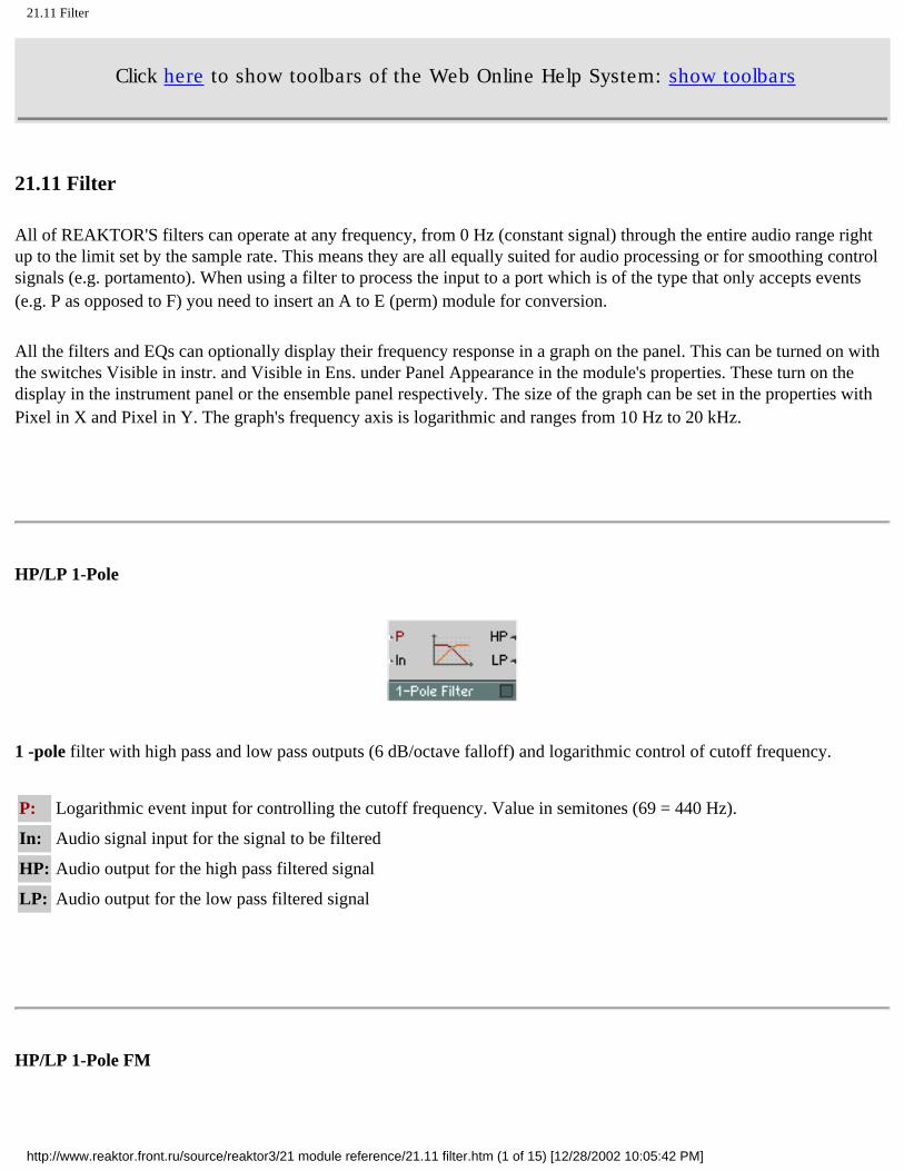
21.11 Filter
Click here to show toolbars of the Web Online Help System: show toolbars
21.11 Filter
All of REAKTOR'S filters can operate at any frequency, from 0 Hz (constant signal) through the entire audio range right up to the limit set by the sample rate. This means they are all equally suited for audio processing or for smoothing control signals (e.g. portamento). When using a filter to process the input to a port which is of the type that only accepts events (e.g. P as opposed to F) you need to insert an A to E (perm) module for conversion.
All the filters and EQs can optionally display their frequency response in a graph on the panel. This can be turned on with the switches Visible in instr. and Visible in Ens. under Panel Appearance in the module's properties. These turn on the display in the instrument panel or the ensemble panel respectively. The size of the graph can be set in the properties with Pixel in X and Pixel in Y. The graph's frequency axis is logarithmic and ranges from 10 Hz to 20 kHz.
HP/LP 1-Pole
1 -pole filter with high pass and low pass outputs (6 dB/octave falloff) and logarithmic control of cutoff frequency.
P: Logarithmic event input for controlling the cutoff frequency. Value in semitones (69 = 440 Hz).
In: Audio signal input for the signal to be filtered
HP: Audio output for the high pass filtered signal
LP: Audio output for the low pass filtered signal
HP/LP 1-Pole FM
http://www.reaktor.front.ru/source/reaktor3/21 module reference/21.11 filter.htm (1 of 15) [12/28/2002 10:05:42 PM]

21.11 Filter
1-pole filter with high pass and low pass outputs (6 dB/octave falloff), logarithmic and linear control of cutoff frequency.
P: Logarithmic event input for controlling the cutoff frequency. Value in semitones (69 = 440 Hz).
F: Audio input for linear control of the cutoff frequency. Value in Hz. P and F together determine the oscillator frequency.
In: Audio signal input for the signal to be filtered
HP: Audio output for the high pass filtered signal
LP: Audio output for the low pass filtered signal
Multi 2-Pole
2-pole filter with high pass and low pass outputs (12 dB/octave falloff), band pass (above and below each 6 dB/octave falloff), variable resonance, and logarithmic control of cutoff frequency.
The pass band gain is always 1 (0 dB), whereas the gain at the cutoff frequency increases with the resonance. Caution: Very large amplitudes are generated when Res is almost 1.
P: Logarithmic event input for controlling the cutoff frequency. Value in semitones (69 = 440 Hz).
Res: Event input for controlling the filter's resonance/damping. Range of values 0 (maximal damping, no resonance) to 1 (no damping, maximal resonance, self oscillation!). At high resonance the filter's Q-factor = frequency [Hz] / bandwidth [Hz] = 1 / (2 - 2 Res).
In: Audio signal input for the signal to be filtered
HP: Audio output for the high pass filtered signal
BP: Audio output for the band pass filtered signal
http://www.reaktor.front.ru/source/reaktor3/21 module reference/21.11 filter.htm (2 of 15) [12/28/2002 10:05:42 PM]

21.11 Filter
LP: Audio output for the low pass filtered signal
Multi 2-Pole FM
2-pole filter with high pass and low pass outputs (12 dB/octave falloff), band pass (above and below each 6 dB/octave falloff), variable resonance, logarithmic and linear control of cutoff frequency.
The pass band gain is always 1 (0 dB), whereas the gain at the cutoff frequency increases with the resonance. Caution: Very large amplitudes are generated when Res is almost 1.
P: Logarithmic event input for controlling the cutoff frequency. Value in semitones (69 = 440 Hz).
F: Audio input for linear control of the cutoff frequency. Value in Hz. P and F together determine the oscillator frequency.
Res: Event input for controlling the filter's resonance/damping. Range of values 0 (maximal damping, no resonance) to 1 (no damping, maximal resonance, self oscillation!). At high resonance the filter's Q-factor = frequency [Hz] / bandwidth [Hz] = 1 / (2 - 2 Res).
In: Audio signal input for the signal to be filtered
HP: Audio output for the high pass filtered signal
BP: Audio output for the band pass filtered signal
LP: Audio output for the low pass filtered signal
Multi/Notch 2-Pole
http://www.reaktor.front.ru/source/reaktor3/21 module reference/21.11 filter.htm (3 of 15) [12/28/2002 10:05:42 PM]
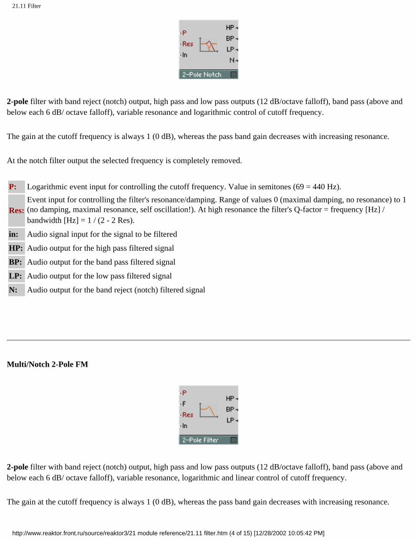
21.11 Filter
2-pole filter with band reject (notch) output, high pass and low pass outputs (12 dB/octave falloff), band pass (above and below each 6 dB/ octave falloff), variable resonance and logarithmic control of cutoff frequency.
The gain at the cutoff frequency is always 1 (0 dB), whereas the pass band gain decreases with increasing resonance.
At the notch filter output the selected frequency is completely removed.
P: Logarithmic event input for controlling the cutoff frequency. Value in semitones (69 = 440 Hz).
Res: Event input for controlling the filter's resonance/damping. Range of values 0 (maximal damping, no resonance) to 1 (no damping, maximal resonance, self oscillation!). At high resonance the filter's Q-factor = frequency [Hz] / bandwidth [Hz] = 1 / (2 - 2 Res).
in: Audio signal input for the signal to be filtered
HP: Audio output for the high pass filtered signal
BP: Audio output for the band pass filtered signal
LP: Audio output for the low pass filtered signal
N: Audio output for the band reject (notch) filtered signal
Multi/Notch 2-Pole FM
2-pole filter with band reject (notch) output, high pass and low pass outputs (12 dB/octave falloff), band pass (above and below each 6 dB/ octave falloff), variable resonance, logarithmic and linear control of cutoff frequency.
The gain at the cutoff frequency is always 1 (0 dB), whereas the pass band gain decreases with increasing resonance.
http://www.reaktor.front.ru/source/reaktor3/21 module reference/21.11 filter.htm (4 of 15) [12/28/2002 10:05:42 PM]

21.11 Filter
At the notch filter output the selected frequency is completely removed.
P: Logarithmic event input for controlling the cutoff frequency. Value in semitones (69 = 440 Hz).
F: Audio input for linear control of the cutoff frequency. Value in Hz. P and F together determine the oscillator frequency.
Res: Event input for controlling the filter's resonance/damping. Range of values 0 (maximal damping, no resonance) to 1 (no damping, maximal resonance, self oscillation!). At high resonance the filter's Q-factor = frequency [Hz] / bandwidth [Hz] = 1 / (2 - 2 Res).
In: Audio signal input for the signal to be filtered
HP: Audio output for the high pass filtered signal
BP: Audio output for the band pass filtered signal
LP: Audio output for the low pass filtered signal
N: Audio output for the band reject (notch) filtered signal
Multi/LP 4-Pole
4-pole filter with low pass (24 dB oil falloff), band pass (12/12 dB/oct) and band/low pass (6/18 dB/oct) outputs, 2-pole high and low pass (12 dB/oct) and band pass (6/6 dB/oct) outputs, variable resonance and logarithmic control of cutoff frequency.
The pass band gain is always 1 (0 dB), whereas the gain at the cutoff frequency increases with the resonance. Caution: Very large amplitudes are generated when Res is almost 1.
P: Logarithmic event input for controlling the cutoff frequency. Value in semitones (69 = 440 Hz).
Res: Event input for controlling the filter's resonance/damping. Range of values 0 (maximal damping, no resonance) to 1 (no damping, maximal resonance, self oscillation!).
In: Audio signal input for the signal to be filtered
http://www.reaktor.front.ru/source/reaktor3/21 module reference/21.11 filter.htm (5 of 15) [12/28/2002 10:05:42 PM]

21.11 Filter
HP2: Audio output for the 2-pole high pass filtered signal
BP2: Audio output for the 2-pole band pass filtered signal
LP2: Audio output for the 2-pole low pass filtered signal
BP4: Audio output for the 4-pole band pass filtered signal
BL4: Audio output for the 4-pole band/low pass filtered signal
LP4: Audio output for the 4-pole low pass filtered signal
Multi/LP 4-Pole FM
4-pole filter with low pass (24 dB/oct falloff), band pass (12/12 dB/oct) and band/low pass (6/18 dB/oct) outputs, 2-pole high and low pass (12 dB/oct) and band pass (6/6 dB/oct) outputs, variable resonance, logarithmic and linear control of cutoff frequency.
The pass band gain is always 1 (0 dB), whereas the gain at the cutoff frequency increases with the resonance. Caution: Very large amplitudes are generated when Res is almost 1.
P: Logarithmic event input for controlling the cutoff frequency. Value in semitones (69 = 440 Hz).
F: Audio input for linear control of the cutoff frequency. Value in Hz. P and F together determine the oscillator frequency.
Res: Event input for controlling the filter's resonance/damping. Range of values 0 (maximal damping, no resonance) to 1 (no damping, maximal resonance, self oscillation!).
In: Audio signal input for the signal to be filtered
HP2: Audio output for the 2-pole high pass filtered signal
BP2: Audio output for the 2-pole band pass filtered signal
LP2: Audio output for the 2-pole low pass filtered signal
BP4: Audio output for the 4-pole band pass filtered signal
BL4: Audio output for the 4-pole band/low pass filtered signal
http://www.reaktor.front.ru/source/reaktor3/21 module reference/21.11 filter.htm (6 of 15) [12/28/2002 10:05:43 PM]

21.11 Filter
LP4: Audio output for the 4-pole low pass filtered signal
Multi/HP 4-Pole
4-pole filter with high pass (24 dB/oct falloff), band pass (12/12 dB/oct) and band/high pass (18/6 dB/oct) outputs, 2-pole high and low pass (12 dB/oct) and band pass (6/6 dB/oct) outputs, variable resonance and logarithmic control of cutoff frequency.
The pass band gain is always 1 (0 dB), whereas the gain at the cutoff frequency increases with the resonance. Caution: Very large amplitudes are generated when Res is almost 1.
P: Logarithmic event input for controlling the cutoff frequency. Value in semitones (69 = 440 Hz).
Res: Event input for controlling the filter's resonance/damping. Range of values 0 (maximal damping, no resonance) to 1 (no damping, maximal resonance, self oscillation!).
In: Audio signal input for the signal to be filtered
HP2: Audio output for the 2-pole high pass filtered signal
BP2: Audio output for the 2-pole band pass filtered signal
LP2: Audio output for the 2-pole low pass filtered signal
HP4: Audio output for the 4-pole high pass filtered signal
BH4: Audio output for the 4-pole band/high pass filtered signal
BP4: Audio output for the 4-pole band pass filtered signal
Multi/HP 4-Pole FM
http://www.reaktor.front.ru/source/reaktor3/21 module reference/21.11 filter.htm (7 of 15) [12/28/2002 10:05:43 PM]

21.11 Filter
4-pole filter with high pass (24 dB/oct falloff), band pass (12/12 dB/oct) and band/high pass (18/6 dB/oct) outputs, 2-pole high and low pass (12 dB/oct) and band pass (6/6 dB/oct) outputs, variable resonance, logarithmic and linear control of cutoff frequency.
The pass band gain is always 1 (0 dB), whereas the gain at the cutoff frequency increases with the resonance. Caution: Very large amplitudes are generated when Res is almost 1.
P: Logarithmic event input for controlling the cutoff frequency. Value in semitones (69 = 440 Hz).
F: Audio input for linear control of the cutoff frequency. Value in Hz. P and F together determine the oscillator frequency.
Res: Event input for controlling the filter's resonance/damping. Range of values 0 (maximal damping, no resonance) to 1 (no damping, maximal resonance, self oscillation!).
In: Audio signal input for the signal to be filtered
HP2: Audio output for the 2-pole high pass filtered signal
BP2: Audio output for the 2-pole band pass filtered signal
LP2: Audio output for the 2-pole low pass filtered signal
HP4: Audio output for the 4-pole high pass filtered signal
BH4: Audio output for the 4-pole band/high pass filtered signal
BP4: Audio output for the 4-pole band pass filtered signal
Pro-52 Filter
http://www.reaktor.front.ru/source/reaktor3/21 module reference/21.11 filter.htm (8 of 15) [12/28/2002 10:05:43 PM]

21.11 Filter
Filter taken from the Pro-52 virtual analog synthesizer. It is a 4-pole low pass filter (24 dB/oct falloff) with variable resonance and logarithmic and linear control of cutoff frequency.
The filter goes into self-oscillation when Res approaches the value 1. The amplitude of the self-oscillation is approximately 1.
P: Logarithmic event input for controlling the cutoff frequency. Value in semitones (69 = 440 Hz).
F: Audio input for linear control of the cutoff frequency. Value in Hz. P and F together determine the oscillator frequency.
Res: Event input for controlling the filter's resonance/damping. Range of values 0 (maximal damping, no resonance) to 1 (no damping, maximal resonance, self-oscillation).
In: Audio signal input for the signal to be filtered
Out: Audio output for the 4-pole low pass filtered signal
Ladder Filter FM
Filter modelled on the classic ladder circuit patented by Bob Moog. It is a 4-pole filter with different low pass outputs: 24 dB/oct, 18 dB/oct , 12 dB/oct and 6 dB/oct falloff. It also has variable resonance and logarithmic and linear control of cutoff frequency.
The saturation characteristic of the analog circuit can optionally be simulated by turning on Distortion in the properties. When Distortion is enabled, the filter goes into self-oscillation when the value of Res is 1 or more. The amplitude of the self-oscillation is approximately 1 when Res is just above 1, but can be much larger when driving Res even higher.
The filter also has options for selecting the quality of the simulation:
Standard, High and Excellent. The effect is particularly noticeable when distortion is turned on. Of course, the higher quality settings come at the price of increased CPU usage.
P: Logarithmic event input for controlling the cutoff frequency. Value in semitones (69 = 440 Hz).
http://www.reaktor.front.ru/source/reaktor3/21 module reference/21.11 filter.htm (9 of 15) [12/28/2002 10:05:43 PM]

21.11 Filter
F: Audio input for linear control of the cutoff frequency. Value in Hz. P and F together determine the oscillator frequency.
Res: Event input for controlling the filter's resonance/damping. Range of values 0 (no resonance) to 1 (maximal resonance, self-oscillation). Values above 1 are possible in Distortion mode.
In: Audio signal input for the signal to be filtered
LP1: Audio output for the 6 dB/oct low pass filtered signal
LP2: Audio output for the 12 dB/oct low pass filtered signal
LP3: Audio output for the 18 dB/oct low pass filtered signal
LP4: Audio output for the 24 dB/oct low pass filtered signal
Ladder Filter
Same as Ladder Filter FM but without the frequency modulation input F.
Peak EQ
Parametric equalizer with adjustable boost/cut, band width and logarithmic frequency control. With the Peak EQ a specific frequency in the signal and a narrow or wide band of frequencies around it can be amplified or attenuated. More distant frequencies are not affected.
http://www.reaktor.front.ru/source/reaktor3/21 module reference/21.11 filter.htm (10 of 15) [12/28/2002 10:05:43 PM]
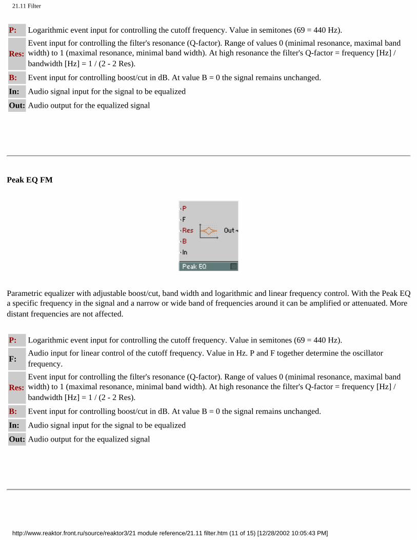
21.11 Filter
P: Logarithmic event input for controlling the cutoff frequency. Value in semitones (69 = 440 Hz).
Res: Event input for controlling the filter's resonance (Q-factor). Range of values 0 (minimal resonance, maximal band width) to 1 (maximal resonance, minimal band width). At high resonance the filter's Q-factor = frequency [Hz] / bandwidth [Hz] = 1 / (2 - 2 Res).
B: Event input for controlling boost/cut in dB. At value B = 0 the signal remains unchanged.
In: Audio signal input for the signal to be equalized
Out: Audio output for the equalized signal
Peak EQ FM
Parametric equalizer with adjustable boost/cut, band width and logarithmic and linear frequency control. With the Peak EQ a specific frequency in the signal and a narrow or wide band of frequencies around it can be amplified or attenuated. More distant frequencies are not affected.
P: Logarithmic event input for controlling the cutoff frequency. Value in semitones (69 = 440 Hz).
F: Audio input for linear control of the cutoff frequency. Value in Hz. P and F together determine the oscillator frequency.
Res: Event input for controlling the filter's resonance (Q-factor). Range of values 0 (minimal resonance, maximal band width) to 1 (maximal resonance, minimal band width). At high resonance the filter's Q-factor = frequency [Hz] / bandwidth [Hz] = 1 / (2 - 2 Res).
B: Event input for controlling boost/cut in dB. At value B = 0 the signal remains unchanged.
In: Audio signal input for the signal to be equalized
Out: Audio output for the equalized signal
http://www.reaktor.front.ru/source/reaktor3/21 module reference/21.11 filter.htm (11 of 15) [12/28/2002 10:05:43 PM]

21.11 Filter
High Shelf EQ
Parametric equalizer with high shelving characteristic, adjustable boost/ cut, band width and logarithmic frequency control.
The level of frequencies above the comer frequency is raised or reduced by the set amount. Low frequencies are not affected.
P: Logarithmic event input for controlling the cutoff frequency. Value in semitones (69 = 440 Hz).
B: Event input for controlling boost/cut in dB. At value B = 0 the signal remains unchanged.
In: Audio signal input for the signal to be equalized
Out: Audio output for the equalized signal
High Shelf EQ FM
Parametric equalizer with high shelving characteristic, adjustable boost/ cut, band width and logarithmic and linear frequency control.
The level of frequencies above the comer frequency is raised or reduced by the set amount. Low frequencies are not affected.
P: Logarithmic event input for controlling the cutoff frequency. Value in semitones (69 = 440 Hz).
F: Audio input for linear control of the cutoff frequency. Value in Hz. P and F together determine the oscillator frequency.
http://www.reaktor.front.ru/source/reaktor3/21 module reference/21.11 filter.htm (12 of 15) [12/28/2002 10:05:43 PM]
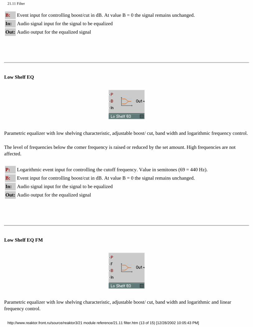
21.11 Filter
B: Event input for controlling boost/cut in dB. At value B = 0 the signal remains unchanged.
In: Audio signal input for the signal to be equalized
Out: Audio output for the equalized signal
Low Shelf EQ
Parametric equalizer with low shelving characteristic, adjustable boost/ cut, band width and logarithmic frequency control.
The level of frequencies below the comer frequency is raised or reduced by the set amount. High frequencies are not affected.
P: Logarithmic event input for controlling the cutoff frequency. Value in semitones (69 = 440 Hz).
B: Event input for controlling boost/cut in dB. At value B = 0 the signal remains unchanged.
In: Audio signal input for the signal to be equalized
Out: Audio output for the equalized signal
Low Shelf EQ FM
Parametric equalizer with low shelving characteristic, adjustable boost/ cut, band width and logarithmic and linear frequency control.
http://www.reaktor.front.ru/source/reaktor3/21 module reference/21.11 filter.htm (13 of 15) [12/28/2002 10:05:43 PM]

21.11 Filter
The level of frequencies below the comer frequency is raised or reduced by the set amount. High frequencies are not affected.
P: Logarithmic event input for controlling the cutoff frequency. Value in semitones (69 = 440 Hz).
F: Audio input for linear control of the cutoff frequency. Value in Hz. P and F together determine the oscillator frequency.
B: Event input for controlling boost/cut in dB. At value B = 0 the signal remains unchanged.
In: Audio signal input for the signal to be equalized
Out: Audio output for the equalized signal
Differentiator
The differentiator gives the slope of the input signal in change units per millisecond. The effect is like a high pass filter where the amplification is proportional to frequency. Unity gain at 159 Hz.
In: Audio signal input for the signal to be differentiated
Out: Audio output for the differentiated signal
Integrator
Integrator with Reset input. The output value changes with a slope given by the input in change units per millisecond. The effect is like a low pass filter where amplification is proportional to 1/frequency. Unity gain at 159 Hz.
http://www.reaktor.front.ru/source/reaktor3/21 module reference/21.11 filter.htm (14 of 15) [12/28/2002 10:05:43 PM]
21.11 Filter
In: Audio signal input for the signal to be integrated
Set: Event input for the reset. When an event is received, the output signal is set to the value of the event.
Out: Audio output for the integrated signal
http://www.reaktor.front.ru/source/reaktor3/21 module reference/21.11 filter.htm (15 of 15) [12/28/2002 10:05:43 PM]

21.12 Delay
Click here to show toolbars of the Web Online Help System: show toolbars
21.12 Delay
Static Delay
Polyphonic delay line for audio signals. The input signal appears at the output with a delay corresponding to the set time. The delay time is controlled by events at the Dly input and is always rounded to an integer number of samples.
The upper limit for the delay time can be adjusted in the module's properties dialog window (default: 1 second) and affects the memory usage. How big this value can be set depends on the amount of available RAM storage in the computer. At a sample rate of 44.1 kHz you need 172 kB of RAM for each second of buffer length and for each voice. For one minute you need 10 MB.
Dly: Event input for controlling the delay time. Value in milliseconds.
In: Audio input for the signal to be delayed.
Out: Audio output for the delayed signal.
Modulation Delay
http://www.reaktor.front.ru/source/reaktor3/21 module reference/21.12 delay.htm (1 of 4) [12/28/2002 10:05:46 PM]
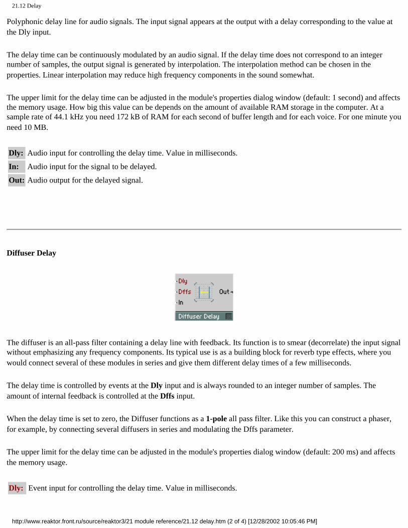
21.12 Delay
Polyphonic delay line for audio signals. The input signal appears at the output with a delay corresponding to the value at the Dly input.
The delay time can be continuously modulated by an audio signal. If the delay time does not correspond to an integer number of samples, the output signal is generated by interpolation. The interpolation method can be chosen in the properties. Linear interpolation may reduce high frequency components in the sound somewhat.
The upper limit for the delay time can be adjusted in the module's properties dialog window (default: 1 second) and affects the memory usage. How big this value can be depends on the amount of available RAM storage in the computer. At a sample rate of 44.1 kHz you need 172 kB of RAM for each second of buffer length and for each voice. For one minute you need 10 MB.
Dly: Audio input for controlling the delay time. Value in milliseconds.
In: Audio input for the signal to be delayed.
Out: Audio output for the delayed signal.
Diffuser Delay
The diffuser is an all-pass filter containing a delay line with feedback. Its function is to smear (decorrelate) the input signal without emphasizing any frequency components. Its typical use is as a building block for reverb type effects, where you would connect several of these modules in series and give them different delay times of a few milliseconds.
The delay time is controlled by events at the Dly input and is always rounded to an integer number of samples. The amount of internal feedback is controlled at the Dffs input.
When the delay time is set to zero, the Diffuser functions as a 1-pole all pass filter. Like this you can construct a phaser, for example, by connecting several diffusers in series and modulating the Dffs parameter.
The upper limit for the delay time can be adjusted in the module's properties dialog window (default: 200 ms) and affects the memory usage.
Dly: Event input for controlling the delay time. Value in milliseconds.
http://www.reaktor.front.ru/source/reaktor3/21 module reference/21.12 delay.htm (2 of 4) [12/28/2002 10:05:46 PM]

21.12 Delay
Dffs: Event input for controlling the diffusion coefficient. Range of values: -1 ... 1. Dffs = 0 : the module is a pure delay, Dffs = 1 : output = input, Dffs = -1 : output = -input. The most useful values for Dffs are near 0.5.
In: Audio input for the signal to be diffused.
Out: Audio output for the diffused signal.
Grain Delay
A delay line and pitch-shifter for audio signals. The input signal appears at the outputs with a delay corresponding to the set time at the Dly input, transposed by the amount set at the P input in semitones.
The input signal is "chopped-up" into sound particles, whose size is controlled by the Granularity input (Gr). The "roughness" of the resulting sound can be controlled via the Smoothness input (Sm). The position of the sound particles in the stereo field is set at the Pan input.
The delay time of the Grain Delay can be varied without affecting the pitch. Interesting effects are possible in combination with random/noise generators.
In the properties dialog window the playback quality and also the upper limit of the delay time can be set. The available maximum delay time can deviate from the set amount by up to 50 %.
P: Logarithmic audio control input for transposing in semitones (Pitch).
Dly: Audio control input for the delay time in milliseconds.
Gr: Audio control input for the granularity of the re-synthesis process, in milliseconds. This parameter sets the size of the sound particles used for the re-synthesis.
Sm: Audio control input for the Smoothness of the re-synthesis process. This affects the formation of the sound particles. Low settings result generally in a rougher sound.
Pan: Audio control input for stereo field positioning (-1 = Left, 0 = Middle, 1 = Right).
http://www.reaktor.front.ru/source/reaktor3/21 module reference/21.12 delay.htm (3 of 4) [12/28/2002 10:05:46 PM]

21.12 Delay
A: Audio control input for the output amplitude.
In: Input for the audio signal to be delayed.
L: Audio output for the left channel of the delay.
R: Audio output for the right channel of the delay.
Dly: Polyphonic event output, which is set to the current delay time. This output always produces an event whenever a new sound particle is made.
Multi-Tap Delay
Multi tap delay line for audio signals. If the set delay time corresponds to a non-integer number of sample, interpolation occurs. The interpolation method can be set in the properties.
The outputs are usually connected to a mixer or scanner.
In: Audio input for the signal to be delayed.
Dly1..8: Audio inputs for control of the delay time in milliseconds. Typ range: [0...1000].
Out1..8: .Audio outputs for the delayed input signal. Out1 is delayed by time Dly1, Out2 by Dly2 etc.
http://www.reaktor.front.ru/source/reaktor3/21 module reference/21.12 delay.htm (4 of 4) [12/28/2002 10:05:46 PM]

21.13 Shaper
Click here to show toolbars of the Web Online Help System: show toolbars
21.13 Shaper
Shaper 1 BP
Signal shaper with piecewise linear input/output curve and one breakpoint.
The slope of the curve above the breakpoint can be adjusted. Signal values below the breakpoint are passed unchanged.
BP: Audio input for controlling the level of the breakpoint
Sl: Audio input for controlling the slope of the upper part of the input/output curve (1 = no change in signal).
In: Audio input for the signal to be shaped.
Out: Audio output for the shaped signal.
Shaper 2 BP
http://www.reaktor.front.ru/source/reaktor3/21 module reference/21.13 shaper.htm (1 of 8) [12/28/2002 10:05:53 PM]
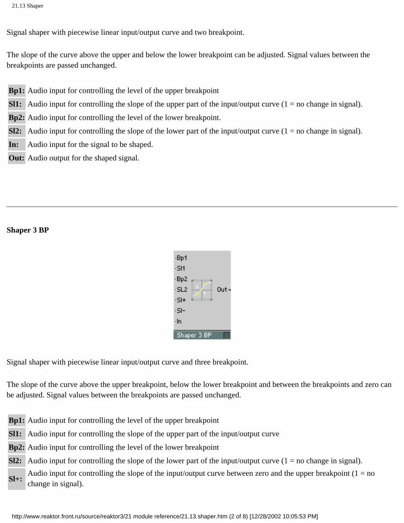
21.13 Shaper
Signal shaper with piecewise linear input/output curve and two breakpoint.
The slope of the curve above the upper and below the lower breakpoint can be adjusted. Signal values between the breakpoints are passed unchanged.
Bp1: Audio input for controlling the level of the upper breakpoint
Sl1: Audio input for controlling the slope of the upper part of the input/output curve (1 = no change in signal).
Bp2: Audio input for controlling the level of the lower breakpoint.
Sl2: Audio input for controlling the slope of the lower part of the input/output curve (1 = no change in signal).
In: Audio input for the signal to be shaped.
Out: Audio output for the shaped signal.
Shaper 3 BP
Signal shaper with piecewise linear input/output curve and three breakpoint.
The slope of the curve above the upper breakpoint, below the lower breakpoint and between the breakpoints and zero can be adjusted. Signal values between the breakpoints are passed unchanged.
Bp1: Audio input for controlling the level of the upper breakpoint
Sl1: Audio input for controlling the slope of the upper part of the input/output curve
Bp2: Audio input for controlling the level of the lower breakpoint
Sl2: Audio input for controlling the slope of the lower part of the input/output curve (1 = no change in signal).
Sl+: Audio input for controlling the slope of the input/output curve between zero and the upper breakpoint (1 = no change in signal).
http://www.reaktor.front.ru/source/reaktor3/21 module reference/21.13 shaper.htm (2 of 8) [12/28/2002 10:05:53 PM]

21.13 Shaper
Sl-: Audio input for controlling the slope of the input/output curve between the lower breakpoint and zero (1 = no change in signal).
In: Audio input for the signal to be shaped
Out: Audio output for the shaped signal
Parabolic Shaper
Signal shaper with parabolic (2nd order polynomial) input/output curve.
The linear and square parts of the signal can be adjusted ( Out = Lin In + Par In2).
Lin: Audio input for controlling the level of the linear, undistorted part
Par: Audio input for controlling the level of the square, distorted part
In: Audio input for the signal to be shaped
Out: Audio output for the shaped signal
Cubic Shaper
Signal shaper with cubic parabolic (3rd order polynomial) input/output curve.
http://www.reaktor.front.ru/source/reaktor3/21 module reference/21.13 shaper.htm (3 of 8) [12/28/2002 10:05:53 PM]

21.13 Shaper
The linear, square and cubic parts of the signal can be adjusted ( Out = Lin In + Par In2 + Cub In3).
Lin: Audio input for controlling the level of the linear, undistorted part
Par: Audio input for controlling the level of the square, distorted part
Cub: Audio input for controlling the level of the cubic, distorted part
In: Audio input for the signal to be shaped
Out: Audio output for the shaped signal
Ctrl. Shaper 1 BP
Event signal shaper with piecewise linear input/output curve and one fixed breakpoint. The output produced by linear interpolation between the given points.
100: Output value at In = 1 (100%).
50: Output value at the breakpoint at in = 0.5 (50%).
0: Output value at in = 0 (0%).
In: Event input for the signal to be shaped
Out: Event output for the shaped signal
Ctrl. Shaper 2 BP
http://www.reaktor.front.ru/source/reaktor3/21 module reference/21.13 shaper.htm (4 of 8) [12/28/2002 10:05:53 PM]

21.13 Shaper
Event signal shaper with piecewise linear input/output curve and two fixed breakpoints. The output produced by linear interpolation between the given points.
100: Output value at in = 1 (100%).
66: Output value at the upper breakpoint at in = 0.66 (66%).
33: Output value at the lower breakpoint at in = 0.33 (33%).
0: Output value at in = 0 (0%).
In: Event input for the signal to be shaped
Out: Event output for the shaped signal
Ctrl. Shaper 3 BP
Event signal shaper with piecewise linear input/output curve and three fixed breakpoints. The output produced by linear interpolation between the given points.
100: Output value at In = 1 (100%).
75: Output value at the upper breakpoint at in = 0.75 (75%).
50: Output value at the middle breakpoint at in = 0.5 (50%).
25: Output value at the lower breakpoint at In = 0.25 (25%).
http://www.reaktor.front.ru/source/reaktor3/21 module reference/21.13 shaper.htm (5 of 8) [12/28/2002 10:05:53 PM]

21.13 Shaper
0: Output value at In = 0 (0%).
In: Event input for the signal to be shaped
Out: Event output for the shaped signal
Event Expon. (A)
Event exponential function with scaling as for level control inputs (e.g. on a Mixer module). With this converter a linear amplitude control input can be controlled like a level control input with a logarithmic event value in dB.
Lvl: Event input for the logarithmic amplitude control signal. 0 [dB] at A=l,20[dB] at A=10
A: Event output for the linear amplitude control signal
Event Expon. (F)
Event exponential function with scaling as for pitch control inputs (e.g. on an oscillator module). With this converter a linear frequency control input can be controlled like a pitch control input with a logarithmic event value.
P: Event input for the logarithmic pitch control signal. Value in semitones, 69 = A3 (440 Hz).
F: Event output for the linear frequency control signal
http://www.reaktor.front.ru/source/reaktor3/21 module reference/21.13 shaper.htm (6 of 8) [12/28/2002 10:05:53 PM]

21.13 Shaper
Event Log (A)
Logarithmic converter for level control. A linear amplitude control signal is converted to a logarithmic level control signal (in dB).
This converter can also be used to control logarithmic time control inputs in dB1ms (e.g. in envelopes) using linear time values in ms (according to the table on page 122).
A: Event input for the amplitude control signal
Lvl: Event output for the logarithmic level control signal.0 [dB] at A = 1,20[dB] at A=10
Event Log (F)
Logarithmic converter for level control. A linear amplitude control signal is converted to a logarithmic level control signal (in dB).
F: Event input for the linear frequency control signal
P: Event output for the logarithmic pitch control signal.Value in semitones, 69 = A3 (440 Hz).
Audio Expon. (A)
http://www.reaktor.front.ru/source/reaktor3/21 module reference/21.13 shaper.htm (7 of 8) [12/28/2002 10:05:53 PM]

21.13 Shaper
Audio exponential function with scaling as for logarithmic amplitude control inputs. With this converter a linear control input can be controlled with a logarithmic audio signal.
Lvl: Audio input for the logarithmic amplitude control signal.0 [dB] at A= 1,20[dB] at A= 10
A: Audio output for the linear amplitude control signal
Audio Expon. (F)
Audio exponential function with scaling as for logarithmic frequency control inputs. With this converter a linear control input can be controlled with a logarithmic audio signal.
P: Audio input for the logarithmic frequency control signal.Value in semitones, 69 = A3 (440 Hz).
F: Audio output for the linear frequency control signal. Value in Hz
http://www.reaktor.front.ru/source/reaktor3/21 module reference/21.13 shaper.htm (8 of 8) [12/28/2002 10:05:53 PM]

21.14 Audio Modifier
Click here to show toolbars of the Web Online Help System: show toolbars
21.14 Audio Modifier
Saturator
Distortion with a smoothly rounded input-output curve for soft transition to saturation. The output value is limited to ±2 (reached for input values bigger than ±4). Very small input values are not changed.
In: Audio input for signal to be saturated
Out: Audio output for saturated signal
Clipper
Distortion with a hard clipping and adjustable upper and lower limit. When the input signal exceeds the upper limit it is clipped to the limit value, similarly for the lower limit. Signal values between the limits are passed unchanged.
Max: Audio input for controlling the upper limit of the signal
Min: Audio input for controlling the lower limit of the signal
http://www.reaktor.front.ru/source/reaktor3/21 module reference/21.14 audio modifier.htm (1 of 7) [12/28/2002 10:06:04 PM]
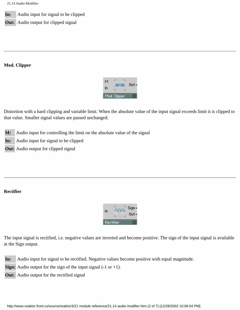
21.14 Audio Modifier
In: Audio input for signal to be clipped
Out: Audio output for clipped signal
Mod. Clipper
Distortion with a hard clipping and variable limit. When the absolute value of the input signal exceeds limit it is clipped to that value. Smaller signal values are passed unchanged.
M: Audio input for controlling the limit on the absolute value of the signal
In: Audio input for signal to be clipped
Out: Audio output for clipped signal
Rectifier
The input signal is rectified, i.e. negative values are inverted and become positive. The sign of the input signal is available at the Sign output.
In: Audio input for signal to be rectified. Negative values become positive with equal magnitude.
Sign: Audio output for the sign of the input signal (-1 or +1).
Out: Audio output for the rectified signal
http://www.reaktor.front.ru/source/reaktor3/21 module reference/21.14 audio modifier.htm (2 of 7) [12/28/2002 10:06:04 PM]

21.14 Audio Modifier
Mirror 1 Level
Distortion by signal value mirroring with adjustable mirror level. Signal values above the mirror level are "reflected" at the level to end up smaller. Signal values below the mirror level are passed unchanged.
Max: Audio input for controlling the mirror level
In: Audio input for signal to be modified
Out: Audio output for the modified signal
Mirror 2 Levels
Distortion by double signal value mirroring with adjustable mirror levels. Signal values above the upper mirror level are "reflected" at the level to end up smaller, those below the lower mirror level are "reflected" at that level to end up larger. Signal values in the middle are passed unchanged.
Max: Audio input for controlling the upper mirror level
Min: Audio input for controlling the lower mirror level
In: Audio input for signal to be modified
Out: Audio output for the modified signal
http://www.reaktor.front.ru/source/reaktor3/21 module reference/21.14 audio modifier.htm (3 of 7) [12/28/2002 10:06:04 PM]

21.14 Audio Modifier
Chopper
Chopper Modulator that switches amplification of the input signal between a variable factor and one.
When the modulation signal is positive, the input signal is multiplied by the value X. When the modulation signal is negative, the input is unchanged.
M: Audio input for the modulation signal (only the sign is relevant).
X: Audio input for controlling the amplification factor used when M is positive.
In: Audio input for the signal to be chopped.
Out: Audio output for the chopped signal
Slew Limiter
Slew rate limiter with separately adjustable maximum rate for rising and falling signals. The output signal tracks the input signal, but for fast movement and jumps at the input, the output follows with a limited rate of change (ramp) until its value reaches that of the input signal.
Up: Audio input for controlling the maximum slew rate for rising signals. Value in units of 1/sec
Dn: Audio input for controlling the maximum slew rate for falling signals. Value in units of 1/sec
In: Audio input for signal to be slew rate limited
Out: Audio output for slew rate limited signal
http://www.reaktor.front.ru/source/reaktor3/21 module reference/21.14 audio modifier.htm (4 of 7) [12/28/2002 10:06:04 PM]

21.14 Audio Modifier
Peak Detector
Detector for the peak amplitude. The input signal is rectified and smoothed with an adjustable release time. The attack time is zero.
The result of the Peak Detector's action is that the output value follows the amplitude envelope of the input - use this module as an envelope follower.
Rel: Logarithmic event input for controlling the release time. 0 = 1 ms, 20 = 10 ms, 40 = 100 ms (i.e. in dB1ms).
In: Audio input for signal to be detected
Out: Audio output for the signal
Sample & Hold
rocket222.jpg
Sample & Hold with clock input.
When the clock signal rises above zero, the current input value is passed to the output and held there until the next clock pulse. The result is a step waveform at the output.
C: Audio input for the clock signal. The input is sampled on a rising edge here.
In: Audio input for the signal to be sampled
Out: Audio output for the sampled signal
http://www.reaktor.front.ru/source/reaktor3/21 module reference/21.14 audio modifier.htm (5 of 7) [12/28/2002 10:06:04 PM]

21.14 Audio Modifier
Quantizer
Quantizer for audio signals, with adjustable step size.
The input signal is rounded to the nearest quantization step before being output.
St: Audio input for controlling the size of the quantization step. When set to zero, the signal is not quantized.
In: Audio input for the signal to be quantized
Out: Audio output for the quantized signal
Err: Audio output for the quantization error that is generated by rounding: Err = Out - in
Frequency Divider
Frequency divider (pulse sub-oscillator) with independently controllable high and low level duration.
A pulse wave is generated by counting the zero crossings of the input signal. The frequency of the output waveform will be a fraction of the frequency of the input waveform. The frequency ratio can be adjusted ( fout = 2 fin / ( C+ + C-)). An asymmetric waveform results when C+ and C- have different values.
C+: Audio input for controlling the number of zero crossings of the input signal during the high phase of the output.
C-: Audio input for controlling the number of zero crossings of the input signal during the low phase of the output.
A: Audio input for controlling the amplitude. The output signal moves between +A and -A.
http://www.reaktor.front.ru/source/reaktor3/21 module reference/21.14 audio modifier.htm (6 of 7) [12/28/2002 10:06:04 PM]

21.14 Audio Modifier
In: Audio input for the signal to be frequency-divided
Out: Audio output for the frequency divided signal
Relay 1
On/off switch for audio signals, with control input. The output signal is either zero or equal to the input signal.
Ctrl: Audio input for control of switching. A value greater than zero switches the input to the output.
In: Audio input for the signal to be switched
Out: Audio output for the switched signal
Relay 2
Change-over switch for two audio inputs, with control input. The output signal is equal to the signal of either the first or the second input.
Ctrl: Audio input for control of switching. A value greater than zero switches input 1 to the output, otherwise input 2 is output.
In1: Audio input for the first signal to be switched
In2: Audio input for the second signal to be switched
Out: Audio output for the switched signal
http://www.reaktor.front.ru/source/reaktor3/21 module reference/21.14 audio modifier.htm (7 of 7) [12/28/2002 10:06:04 PM]

21.15 Event Processing
Click here to show toolbars of the Web Online Help System: show toolbars
21.15 Event Processing
Accumulator
Accumulator (sum) for event values. The value of each event at the input is added to the total value stored in the module. The value of the updated sum is sent as an event at the output.
In: Input for the events to be accumulated.
Set: Event input for (re)setting the internal sum. The value of an event at this input determines the new value of the internal sum.
Out: Event output for the accumulated total value.
Counter
Counter controlled by events. A positive event at the appropriate input increases or decreases the output value by one.
Up: Input for counting up. Only events with a positive, non-zero value have an effect here, increasing the output by one.
http://www.reaktor.front.ru/source/reaktor3/21 module reference/21.15 event processing.htm (1 of 14) [12/28/2002 10:06:12 PM]

21.15 Event Processing
Dn: Input for counting down. Only events with a positive, non-zero value have an effect here, decreasing the output by one.
Set: Event input for (re)setting the counter value. The value of an event at this input determines the new value of the counter.
Out: Event output for the counter value.
Frequency Divider
The frequency of the output events is the frequency of the input events divided by a number controlled by the input N. The output signal returns to zero after a certain number of input events, depending on the pulse length which is set with the input W.
N: Control input for the number of input events per output period. (N < 2 : no division, 2 ... 2.99 : division by 2, 3 ... 3.99 : division by 3, etc.).
W: Control input for the pulse width of the output signal. Range of values: 0 ... 1 (0% ... 100%). W = 0 : the gate signal at Out returns to zero already at the next event at In, W = 0.5 : the gate signal at Out returns to zero after half the period, W = 1 : the gate signal at Out stays on all the time.
In: Input for the event (clock) signal to be frequency-divided (e.g. MIDI Clock pulses). Only events with a positive, non-zero value have an effect here.
Rst: Event input for resetting the internal counter in order to force a synchronous start (connect to MIDI Start signal if using the Event Freq. Divider for MIDI synchronization). Requires an event with positive non-zero value.
Out: Event output for the frequency divided signal
Modulo
http://www.reaktor.front.ru/source/reaktor3/21 module reference/21.15 event processing.htm (2 of 14) [12/28/2002 10:06:12 PM]
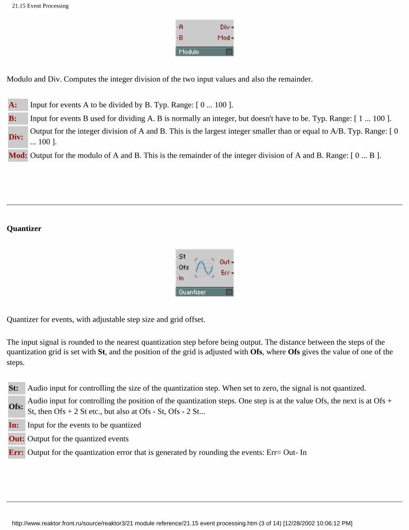
21.15 Event Processing
Modulo and Div. Computes the integer division of the two input values and also the remainder.
A: Input for events A to be divided by B. Typ. Range: [ 0 ... 100 ].
B: Input for events B used for dividing A. B is normally an integer, but doesn't have to be. Typ. Range: [ 1 ... 100 ].
Div: Output for the integer division of A and B. This is the largest integer smaller than or equal to A/B. Typ. Range: [ 0 ... 100 ].
Mod: Output for the modulo of A and B. This is the remainder of the integer division of A and B. Range: [ 0 ... B ].
Quantizer
Quantizer for events, with adjustable step size and grid offset.
The input signal is rounded to the nearest quantization step before being output. The distance between the steps of the quantization grid is set with St, and the position of the grid is adjusted with Ofs, where Ofs gives the value of one of the steps.
St: Audio input for controlling the size of the quantization step. When set to zero, the signal is not quantized.
Ofs: Audio input for controlling the position of the quantization steps. One step is at the value Ofs, the next is at Ofs + St, then Ofs + 2 St etc., but also at Ofs - St, Ofs - 2 St...
In: Input for the events to be quantized
Out: Output for the quantized events
Err: Output for the quantization error that is generated by rounding the events: Err= Out- In
http://www.reaktor.front.ru/source/reaktor3/21 module reference/21.15 event processing.htm (3 of 14) [12/28/2002 10:06:12 PM]

21.15 Event Processing
Randomizer
Event randomizer with adjustable spread.
The arriving events are modified with a random positive or negative offset in the given range (Out = in + X, where -Rng < = X < = Rng).
Rng: Audio input for controlling the range of the random signal modification
In: Event input for signal to be randomized
Out: Event output for randomized signal
Sin/Cos
For each input event, the sine and cosine are computed. An input value of 1.0 corresponds to a full period of the sin and cos functions (i.e. 360 degrees).
In: Input for the argument to the sine function. A value of 1.0 corresponds to one period of the sine function (360 degrees).Typ. Range: [-1 ... 1 ].
Sin: Output for the sine of the input value. Range: [ -1 ... 1 ].
Cos: Output for the cosine of the input value. Range: [ -1 ... 1 ].
Square Root
http://www.reaktor.front.ru/source/reaktor3/21 module reference/21.15 event processing.htm (4 of 14) [12/28/2002 10:06:12 PM]

21.15 Event Processing
Computes the square root of the input values.
In: Event input for the argument to the square root function. For negative input values, the output is zero. Typ. Range: [ 0 ... 100 ].
Out: Output for the square root of the input value. Typ. Range: [ 0 ... 10].
Logic AND
Logic gate for event signals. The output is the logic AND of the two input values, i.e. the output is 1 when both inputs are positive, otherwise the output is 0.
The inputs treat values of zero and below as the logic False state, values above zero are logic True.
Logic OR
Logic gate for event signals. The output is the logic OR of the two input values, i.e. the output is 1 when one or both inputs are positive, otherwise the output is 0.
http://www.reaktor.front.ru/source/reaktor3/21 module reference/21.15 event processing.htm (5 of 14) [12/28/2002 10:06:12 PM]

21.15 Event Processing
The inputs treat values of zero and below as the logic False state, values above zero are logic True.
Logic EXOR
Logic gate for event signals. The output is the logic EXOR of the two input values, i.e. the output is 1 when one but not both inputs are positive, otherwise the output is 0. So in effect one input inverts the logic value of the other input.
The inputs treat values of zero and below as the logic False state, values above zero are logic True.
Logic NOT
Logic gate for event signals. The output is the logic complement of the input value, i.e. the output is 0 when the input is positive, otherwise the output is 1.
The input treats values of zero and below as the logic False state, values above zero are logic True.
Compare
http://www.reaktor.front.ru/source/reaktor3/21 module reference/21.15 event processing.htm (6 of 14) [12/28/2002 10:06:12 PM]

21.15 Event Processing
Comparing Logic Function. Compares the two input values and sets the outputs according to the logic value corresponding to the result of the comparison.
A: Input for the first of two values to be compared.
B: Input for the second of two values to be compared.
>: Output for the result of the comparison "A greater than B". (0 = FALSE, 1 = TRUE)
<: Output for the result of the comparison "A less than B". (0 = FALSE, 1 = TRUE)
=: Output for the result of the comparison "A equal to B". (0 = FALSE, 1 = TRUE)
!=: Output for the result of the comparison "A not equal to B". (0 = FALSE, 1 = TRUE)
Order
Event-Order. An event arriving at the input is transmitted with the same value on all the outputs, but in a well defined order: first it goes to 1, then to 2 and finally to 3. The event travels through ALL the modules in the chain connected to 1, before going to the first module connected to 2 etc.
In: Input for events to be re-transmitted in a defined order.
1: An event is transmitted on this output first.
2: An event is transmitted on this output second.
3: An event is transmitted on this output third.
http://www.reaktor.front.ru/source/reaktor3/21 module reference/21.15 event processing.htm (7 of 14) [12/28/2002 10:06:12 PM]

21.15 Event Processing
Separator
All received events are compared to the threshold value and are sent to either one or the other output.
One use for the separator would be to convert a gate signal to a trigger signal by filtering out the zero events (Thld = 0, Hi = trigger output).
Thld: Audio control input for the threshold value
In: Input for the events to be separated and sent to the two outputs.
Hi: Output for those events whose value is greater than the threshold level.
Lo: Output for those events whose value is less than or equal to the threshold level.
Value
Value-changer for events. Events arriving at the input in have their value replaced with the current value at the Val input, and are then sent with the new value from the output.
This module can also be used as an event-controlled sample&hold module.
In: Input for events to be changed in value.
Val: Input for specifying the new value for the events.
Out: Event output for the value-changed events.
http://www.reaktor.front.ru/source/reaktor3/21 module reference/21.15 event processing.htm (8 of 14) [12/28/2002 10:06:12 PM]

21.15 Event Processing
To Voice
Event To Voice. Events in the monophonic input signal are transmitted to one voice of the polyphonic output signal. The voice number is given by the current value of the V input. Events are discarded when the value at V is not a valid voice number.
This is useful for making polyphonic sequencers, for example.
V: Monophonic input for defining the number of the voice to which an event is to be sent. Typ. Range: [ 1 ... 10 ].
In: Monophonic input for events to be sent to one of the polyphonic voices.
Out: Polyphonic event output. The input events are transmitted (with their original value) on one voice of this polyphonic signal.
From Voice
Event From Voice. One voice is selected from the polyphonic input signal by the current value of the V input. Only events on the selected voice are transmitted to the monophonic output. All events on other voices are discarded.
V: Monophonic input for defining the number of the voice from which events are allowed through. Typ. Range: [ 1 ... 10 ].
In: One voice of this polyphonic event signal is sent to the output.
Out: Monophonic event output. The input events belonging to one voice are transmitted (with their original value) on this monophonic output.
http://www.reaktor.front.ru/source/reaktor3/21 module reference/21.15 event processing.htm (9 of 14) [12/28/2002 10:06:13 PM]

21.15 Event Processing
Router 1
On/off switch for event signals, with control input. The last event passed through is held at the output even while off.
Ctrl: Audio input for control of switching. While the value is greater than zero all input events are passed to the output.
In: Event input for the signal to be switched
Out: Event output for the switched signal. While Ctrl is smaller that zero, the last value is held at the output.
Router 2
Change-over switch for two event inputs, with control input. Depending on the value at the control input, the events from either the first or the second input are passed to the output.
Ctrl: Audio input for control of switching. While the value is greater than zero the events from input 1 are passed to the output, otherwise those from input 2.
ln1: Event input for the first signal to be switched
ln2: Event input for the second signal to be switched
Out: Event output for the switched signal. After switching inputs, the last value from the old input is held at the output until a new event arrives at the new input.
http://www.reaktor.front.ru/source/reaktor3/21 module reference/21.15 event processing.htm (10 of 14) [12/28/2002 10:06:13 PM]

21.15 Event Processing
Router 16
Router for switching between sixteen outputs. The current value at the Ctrl input selects which of the outputs is connected to in. An output only changes value when a new event arrives at the input port, so connecting a constant to in will not work.
Ctrl: Input for control of the router. Events arriving at in are passed to the output selected by the value of this control signal. Changing the Ctrl value by itself does not change any of the outputs, only input events can do that.
In: Events arriving at this input are passed to the output selected by the current value at Ctrl.
0: Events arriving at in are routed to this output when the value at Ctrl is 0 or less..
1-15: Events arriving at in are routed to the appropriate output corresponding to the value at Ctrl.
Timer
http://www.reaktor.front.ru/source/reaktor3/21 module reference/21.15 event processing.htm (11 of 14) [12/28/2002 10:06:13 PM]

21.15 Event Processing
The elapsed time between the two last received events is measured and output as an event. Also, the frequency whose period of oscillation is equal to the measured duration is calculated and output.
In: Polyphonic input for the events whose distance in time is to be measured.
F: Polyphonic event output for the frequency of input events in Hz.
T: Polyphonic event output for the time between events in milliseconds.
Hold
Hold envelope.
When the module is triggered by a positive event at the G input, the event's value is held as the output value until the hold time has passed, after which the output jumps back to zero. The module can be triggered at any time, including retriggering during the hold time.
G: Event input for triggering the envelope. Only events with a positive values (not zero) have an effect here.
H: Input for controlling the hold time in milliseconds.
Out: Event output for the envelope signal.
Event Delay
Delay line for events. An event arriving at the input appears at the output after the set time.
http://www.reaktor.front.ru/source/reaktor3/21 module reference/21.15 event processing.htm (12 of 14) [12/28/2002 10:06:13 PM]

21.15 Event Processing
In this version of REAKTOR only one event can be in the delay at any one time. If another event arrives before the first one has been output, the first event is lost.
Dly: Event input for controlling the delay time. Value in milliseconds
In: Event input for the signal to be delayed.
Out: Event output for the delayed signal
Event Table
Holds a table of data values. Event values can be read from the table, event values can be stored in the table and the table's content can be displayed and edited graphically . The table can be 1-dimensional (a row of values) adressed by X, or 2-dimensional (a matrix of rows and columns, or a set of independent rows) adressed by X and Y.
The value at the output is taken from the table by reading at the position given by the inputs RX and RY. Values arriving at the module's W input are stored in individual cells of the table according to the write position given by the inputs WX and WY.
X is the horizontal position from left to right and Y is the vertical position from top to bottom. The count always starts at 0 for the first element.
The module's panel display can show all the data or a limited region of it. Many options in the properties allow customizing the behaviour.
For full details on properties, menus and keyboard shortcuts, please see the section Table Modules on page 160.
http://www.reaktor.front.ru/source/reaktor3/21 module reference/21.15 event processing.htm (13 of 14) [12/28/2002 10:06:13 PM]

21.15 Event Processing
RX: Audio input for the X-position of a table cell from which the data is read.
RY: Audio input for the Y-position of a table cell from which the data is read. This is used in 2D-mode or for addressing the row number if more than one row exists.
R: Event input for triggering table read operation at the position given by RX and RY. Each event here produces an event at the Out output.
WX: Audio input for the X-position of a table cell in which the data is written.
WY: Audio input for the Y-position of a table cell in which the data is written.
In: Event input for triggering table write operation at the position given by WX and WY. The value of the data written into the table cell is the value of the event arriving at W.
XO: Event input for the horizontal offset of the displayed data region. XO controls the data position that appears in the display (according to View Alignment). The value of XO is in the units specified in properties.
XR: Event input for the horizontal range of the displayed data region. XR controls how many units of data fit in the display, i.e. it lets you zoom into the data.
YO: Event input for the vertical offset of the displayed data region. YO controls the data position that appears in the display (according to View Alignment). The value of YO is in the units specified in properties.
YR: Event input for the vertical range of the displayed data region in 2D-mode. YR controls how many units of data fit in the display, i.e. it lets you zoom into the data.
Out: Event output for data from the cell controlled by the RX, RY and R inputs.
DX: Event output for the size of the horizontal table rows in units.
DY: Event output for the size of the vertical table columns in units.
http://www.reaktor.front.ru/source/reaktor3/21 module reference/21.15 event processing.htm (14 of 14) [12/28/2002 10:06:13 PM]

21.16 Auxiliary
Click here to show toolbars of the Web Online Help System: show toolbars
21.16 Auxiliary
Tapedeck 1-Ch
1-channel Tapedeck module for recording and playback of audio signals. Audio files can be read from and write to either memory or harddisk depending on the properties setting.
In harddisk mode the files are written into the folder you specify in the Reaktor preferences. Reaktor does sample rate converting on the fly and writes the file in the sample rate which is currently used by your audio system.
In memory mode you can display the waveform of a loaded audio file in the panel by ticking the checkbox Picture in the Appearance tab in the properties. The whole waveform for the audio file will fit automatically to the Size of the picture which you enter in the Appearance tab.
Memory mode
By ticking the checkbox Keep audio only in memory in the properties the tapedeck module starts working in memory mode and the Memory section with the Save, Save as and Reload buttons becomes active
The maximum recording time is set with Max Recording Size (sec) in seconds How big this value can be depends on the amount of available RAM storage in the computer At a sample rate of 44 1 kHz you need 86 kB of RAM for each second of buffer length, for one minute you need 5 MB If the buffer memory for the Tapedeck has been chosen too large, virtual memory swaps by the operating system can cause significant hard disk activity during recording This can prevent REAKTOR from processing audio smoothly
http://www.reaktor.front.ru/source/reaktor3/21 module reference/21.16 auxiliary.htm (1 of 9) [12/28/2002 10:06:18 PM]

21.16 Auxiliary
Audio files can be imported for playback with the button Select File in the properties of the Tapedeck module A file that is already imported can be loaded again by selecting Reload, e. g. if it has been changed using a sample editor
When importing an audio file, the length of the tapedeck's memory buffer is adjusted to match the loaded data If you later want to make a recording which is longer than this, you will first need to set a bigger value under Max Recording Size (sec) in the module's properties dialog window The loaded file will automatically set to the current sample rate of Reaktor
Note Be aware that Reaktor converts all audio files stored in the tape-decks in memory mode to the new sample rate whenever Reaktor switches to a new rate So you should avoid changing the sample rate if your ensemble contains memory based audio samples If the audio file is stored on harddisk you can use the Reload button after changing the sample rate to import the file again
A recording can be exported using Save in the properties If the file has already been exported, you will be asked if you want to overwrite the file, e g if you have made a new recording in the Tapedeck With Save as you can store the file under a new name
Harddisk mode
By ticking the checkbox Stream audio from/to harddisk in the properties the tapedeck module starts working in harddisk mode Audio files are written to and read from harddisk directly You can define an audio file for playback using the Select File button With the New button you create a new file named "untitled" (if a file with the name is already existing in your Audio folder you have specified in the Reaktor Preferences the new name will contain an additional number) You can edit this name directly in the name field inside the Properties
If Value is activated in the properties, a display for the file name will appear in the panel By opening the context menu on this box files can also be imported and exported
Rec: Event input for switching recording mode on and off, e g with a gate signal Start of recording on an event with a positive value End of recording on an event with negative or zero value or when the maximum recording time is reached
Play: Event input for switching playback mode on and off, e g with a gate signal Start of playback on an event with a positive value, playback stops on an event with negative or zero value
Loop: Event input for switching loop playback mode on and off When this input receives a positive value, playback starts from the beginning when the end of playback is reached The result is an infinite loop while playback is switched on
In: Monophonic audio input for the signal to be recorded Maximum value ± 1 To record a polyphonic signal a Voice Combiner has to be inserted
Out: Audio output for the playback signal or the signal being recorded
http://www.reaktor.front.ru/source/reaktor3/21 module reference/21.16 auxiliary.htm (2 of 9) [12/28/2002 10:06:18 PM]
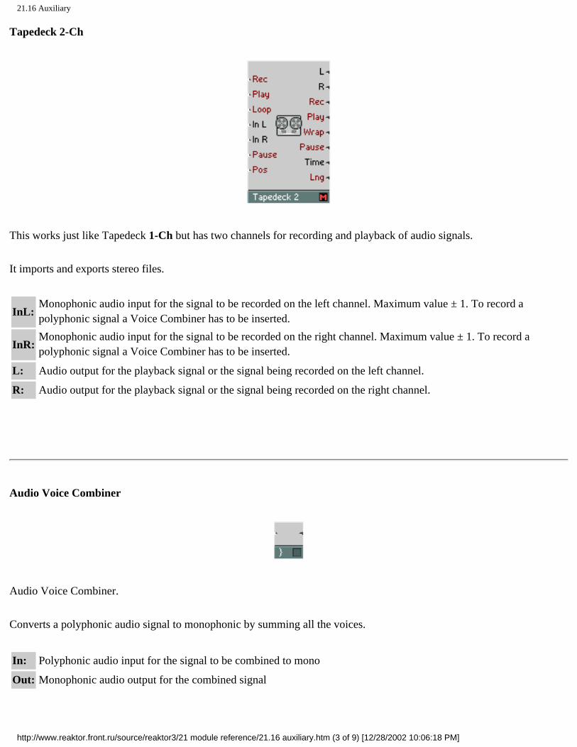
21.16 Auxiliary
Tapedeck 2-Ch
This works just like Tapedeck 1-Ch but has two channels for recording and playback of audio signals.
It imports and exports stereo files.
InL: Monophonic audio input for the signal to be recorded on the left channel. Maximum value ± 1. To record a polyphonic signal a Voice Combiner has to be inserted.
InR: Monophonic audio input for the signal to be recorded on the right channel. Maximum value ± 1. To record a polyphonic signal a Voice Combiner has to be inserted.
L: Audio output for the playback signal or the signal being recorded on the left channel.
R: Audio output for the playback signal or the signal being recorded on the right channel.
Audio Voice Combiner
Audio Voice Combiner.
Converts a polyphonic audio signal to monophonic by summing all the voices.
In: Polyphonic audio input for the signal to be combined to mono
Out: Monophonic audio output for the combined signal
http://www.reaktor.front.ru/source/reaktor3/21 module reference/21.16 auxiliary.htm (3 of 9) [12/28/2002 10:06:18 PM]

21.16 Auxiliary
Event V.C. All
Event Voice Combiner.
Converts a polyphonic event signal to monophonic by sending the events of all the voices to the same monophonic voice.
In: Polyphonic event input for the signal to be combined to mono
Out: Monophonic event output for the combined signal
Event V.C. Max
Event Voice Combiner with maximum value selection.
Converts a polyphonic event signal to monophonic by finding the voice with the highest current value and sending it to the mono output. A polyphonic gate signal input is necessary to recognize active voices.
In: Polyphonic event input for the signal whose maximum value is to be output
G: Polyphonic event input for the gate signal of the polyphonic instrument
Out: Monophonic event output for the maximum value signal
http://www.reaktor.front.ru/source/reaktor3/21 module reference/21.16 auxiliary.htm (4 of 9) [12/28/2002 10:06:18 PM]

21.16 Auxiliary
Event V.C. Min
Event Voice Combiner with minimum value selection.
Converts a polyphonic event signal to monophonic by finding the voice with the lowest current value and sending it to the mono output. A polyphonic gate signal input is necessary to recognize active voices.
In: Polyphonic event input for the signal whose minimum value is to be output
G: Polyphonic event input for the gate signal of the polyphonic instrument
Out: Monophonic event output for the minimum value signal
Event Merge
Merger for event signals. When more than one wire is connected at the input, the output value is that of the last received input event, irrespective of which wire it came from.
When several events with the same value occur in a row, only the first is passed through, the others are filtered out. Like this, superfluous events can be eliminated.
A to E
http://www.reaktor.front.ru/source/reaktor3/21 module reference/21.16 auxiliary.htm (5 of 9) [12/28/2002 10:06:18 PM]

21.16 Auxiliary
Audio to event converter.
The audio signal is sampled using the Control Rate specified in the Settings menu and the values are sent out as a stream of events.
A to E (Trig)
Audio to event converter with trigger input.
When the trigger input signal leaves zero to positive values (rising edge) the audio signal is sampled and output as an event.
T: Audio input for triggering the conversion. Triggers on a rising edge
In: Audio input for signal to be sampled and output as events
Out: Event output for the sampled signal
A to E (Perm)
Audio to event converter with permanent conversion at regular intervals and adjustable sampling frequency.
The audio signal is sampled with the given frequency and output as a stream of events. When running this module at a high frequency (above 1000 Hz) the CPU-Load caused by event processing can rise significantly. Typically F = 200 Hz is sufficient.
http://www.reaktor.front.ru/source/reaktor3/21 module reference/21.16 auxiliary.htm (6 of 9) [12/28/2002 10:06:18 PM]

21.16 Auxiliary
F: Audio input for controlling the sample frequency. Value in Hz
In: Audio input for signal to be sampled and output as events
Out: Event output for the sampled signal
A to Gate
Audio to gate event converter with gate amplitude input.
When the trigger signal leaves zero to positive values (rising edge), the gate signal is switched on with an amplitude of the current value of the amplitude input. When the trigger input returns to zero or negative values (falling edge) the gate signal is switched off.
T: Audio input for triggering the gate signal
A: Audio input for controlling the amplitude of the gate events
G: Event output for the gate event signal
Audio Smoother
Smoother for monophonic event signals with audio output. Typically, a smoother is connected after a fader or button to get smooth transitions.
The jumps in the value of the input event signal are smoothed to ramps. The Transition Time (in milliseconds) can be adjusted in the properties. Exactly after this time has elapsed, the output reaches the same value as the input, assuming that
http://www.reaktor.front.ru/source/reaktor3/21 module reference/21.16 auxiliary.htm (7 of 9) [12/28/2002 10:06:18 PM]

21.16 Auxiliary
no further jumps occurred at the input. The larger the Transition Time, the stronger the smoothing effect.
In: Mono event input for the signal to be smoothed.
Out: Mono audio output for the smoothed signal.
Event Smoother
Smoother for monophonic event signals. Typically, a smoother is connected after a fader or button to get smooth transitions.
The jumps in the value of the input event signal are smoothed to ramps. The Transition Time (in milliseconds) can be adjusted in the properties. Exactly after this time has elapsed, the output reaches the same value as the input, assuming that no further jumps occurred at the input. The larger the Transition Time, the stronger the smoothing effect.
During the transition, events are output with the rate selected as the Control Rate in the Settings menu. The higher the rate, the higher the resolution of the smoothing transition.
In: Mono event input for the signal to be smoothed.
Out: Mono event output for the smoothed signal.
Tempo Info
Source for various information about the Ensemble such as the current Tempo (BPM) or Sample Rate.
The Tempo value is measured in Beats per Second and can be directly connected to an LFO's F input, for example. To get the BPM value, multiply by 60.
http://www.reaktor.front.ru/source/reaktor3/21 module reference/21.16 auxiliary.htm (8 of 9) [12/28/2002 10:06:18 PM]

21.16 Auxiliary
Set Random
Sets the random seed for the pseudo-random number generator used in all Event Randomize, Slow Random and Geiger modules. Only modules in the same instrument are affected. Each unique value starts a different pseudo-random sequence.
Unison Spread
Polyphonic event source for a constant value used to spread out parameters for unison voices.
In unison mode, the different voices that play the same note need to have their parameters spread out a little to make them slightly different so that their sum results in a sound that is fatter, and not just louder. For note pitch this happens automatically and is controlled by the Unison Spread parameter in the instrument properties. Other parameters can be spread out by adding an offset generated by the Unison Spread module.
The value at the module's input determines the amount of spread. At the output you get a value which is different for each of the voices playing the same note. The value only changes once a new note is played.
http://www.reaktor.front.ru/source/reaktor3/21 module reference/21.16 auxiliary.htm (9 of 9) [12/28/2002 10:06:18 PM]

21.17 Conversion Tables for Control Values
Click here to show toolbars of the Web Online Help System: show toolbars
21.17 Conversion Tables for Control Values
Control Value / Time
Conversion of logarithmic time control value in dB1ms, e.g. for envelopes (A, D, D1, D2, R, H). The control value is calculated in dB with the reference value 1 ms. Therefore, the modules Log (A) and Expon. (A) can also be used for conversion.
Control Value Time Time Control Value
-40 10 ns 100ns -20
-30 31,62ns 200ns -14
-20 100ns 500ns -6
-10 316,2ns 1 ms 0
0 1 ms 2 ms 6
10 3,162ms 5 ms 14
20 10ms 10ms 20
30 31,62ms 20ms 26
40 100ms 50ms 34
50 316,2ms 100ms 40
60 1s 200ms 46
70 3,162s 500ms 54
80 10s 1s 60
90 31,62s 2s 66
100 100s 5s 74
110 316,2s 10s 80
120 1000s 20s 86
Conversion Formula:
http://www.reaktor.front.ru/source/reaktor3/21 modul...rence/21.17 conversion tables for control values.htm (1 of 3) [12/28/2002 10:06:21 PM]

21.17 Conversion Tables for Control Values
• Time = 10Value / 20ms
• Value = 20 log( Time / 1 ms )
Pitch / Frequency
Conversion of logarithmic pitch control value, e.g. for oscillators.
Pitch (Semitone) Frequency Frequency Pitch (Semitone)
-100 0,02535 Hz 0,01 Hz -116,10
-90 0,04517 Hz 0,02 Hz -104,10
-80 0,08048 Hz 0,05 Hz -88,24
-70 0,1434 Hz 0,1 Hz -76,24
-60 0,2555 Hz 0,2 Hz -64,24
-50 0,4552 Hz 0,5 Hz -48,38
-40 0,8111 Hz 1 Hz -36,38
-30 1,4453 Hz 2 Hz -24,38
-20 2,5752 Hz 5 Hz -8,51
-10 4,5885 Hz 10 Hz 3,49
0 8,1758Hz 20 Hz 15,49
10 14,568 Hz 50 Hz 31,35
20 25,957 Hz 100 Hz 43,35
30 46,249 Hz 200 Hz 55,35
40 82,407 Hz 500 Hz 71,21
50 146,83 Hz 1000 Hz 83,21
60 261,63 Hz 2000 Hz 95,21
69 440Hz 5000 Hz 111,08
70 466,16 Hz 10000 Hz 123,08
80 830,61 Hz 20000 Hz 135,08
90 1480,0 Hz
100 2637,0 Hz
110 4698,6 Hz
http://www.reaktor.front.ru/source/reaktor3/21 modul...rence/21.17 conversion tables for control values.htm (2 of 3) [12/28/2002 10:06:21 PM]

21.17 Conversion Tables for Control Values
120 8372,0 Hz
130 14917 Hz
Conversion Formula:
• Frequency = 2(P - 69) / 12 • 440 Hz
• Pitch = 69 + 12 log ( Frequency / 440 Hz ) / log ( 2 )
The MIDI note range ( C-2 to G-8 ) corresponds to the pitch range 0 to
http://www.reaktor.front.ru/source/reaktor3/21 modul...rence/21.17 conversion tables for control values.htm (3 of 3) [12/28/2002 10:06:21 PM]