nationalelectricalsafetycode interpretations · feb7,78 223 servicedrops-clearance 232, toground...
TRANSCRIPT

1978-1980
National Electrical Safety Code
Interpretations
1978-1980 inclusive

Library of Congress Catalog Number 81-82081
© Copyright 1981 by
The Institu~ of Electrical and Electronics Engineers, Inc.
No part of this publication may be reproduced in any form,in an electronic retrieval system or otherwise,
without the prior written permission of the publisher.
August 17, 1981 SH08292

ANSI/IEEE C2Interpretations 1978·1980
National.Electrical Safety Code Committee, ANSI C2
National Electrical Safety Code
Interpretations
1978-1980 inclusive
and
Interpretations Prior to the 6th Edition, 1961
Published by
Institute of Electrical and Electronics Engineers, Inc.345 East 47th St., New York, N.Y: 10017

ABSTRACTThis edition includes official interpretations of the National
Electrical Safety Code as made by the Interpretations Subcommit-tee of the National Electrical Safety Code Committee, ANSI C2.
Key words: electric supply stations, overhead electric supply andcommunication lines, underground electric supply and communi-cation lines, clearances to electric supply and communication lines,strength requirements for electric supply and communicationlines.

Contents
Foreword 7
Introduction 9GeneralArrangementProcedure for requesting an interpretation
Numerical Listing by InterpretationRequest (IR) Numbers 11
Interpretations IR 213-283 (1978-1980)Section 9 (Rules 90-99) Grounding Methods 23Part 1 (Rules 100-199) Electrical Supply Stations 34Part 2 (Rules 200-289) Overhead Lines 46Part 3 (Rules 300-399) Underground Lines 194
Interpretations IR 11-91 (1943-1960) 201
Complete Listing of Interpretations Requests,1961-1980 in Rule Number Order 283


Foreword
In response to repeated public inquiries and requests from C2Committee members, the IEEE C2 Secretariat arranged forpublication of Interpretation Requests received and Interpreta-tions made by the National Electrical Safety Code Subcommitteeon Interpretations. The original requests have been lightly editedto remove extraneous matter and focus on the C2 problempresented. Some illustrations have been redrawn for publication.With these exceptions, requests are in the form received.
The first volume, INTERPRETATIONS 1961- 1977, published in1978 included the first interpretation request received for the 6thEdition of Part 2 (IR 92, May 1961) and ended with the lastinterpretation issued in 1977 (IR 212). This new volume, INTER-PRETATIONS 1978 - 1980, continues with IR 213 issued in 1978and ends with the last interpretation issued in 1980 (IR 283). Italso includes all interpretations found in the archives and applyingto the 5th and prior editions of the Code (IR 11 through IR 90).Where no copy of an interpretation request, or an interpretationcould be found in the archives, this fact is noted.
The Secretariat hopes that the publication of all interpretationswill prove helpful to those concerned with the National ElectricalSafety Code.
7


National Electrical Safety Code InterpretationsIntroduction
General: Interpretations are prepared by the National ElectricalSafety Code Interpretations Subcommittee in response to formalrequests received by the NESC Secretariat.This volume contains all interpretations issued on the NESC
through 1980 and not previously published.
Arrangement: This compilation includes a numerical index for allissued interpretations arranged in order of interpretation number,showing the rule number and topic covered. This will be conven-ient for location of the text if only the interpretation requestnumber is available.Interpretation requests and interpretations quoted in full are
arranged according to the primary rule number. Applicable crossreferences are inserted appropriately if a request covers severalrules. If illustrations were provided, they follow the InterpretationRequest text. In the 1977 Edition some changes were made in therule numbers. Exact correspondence of Rule numbers betweenother editions does not exist in some cases. 1977 and 1981 EditionsInterpretations are so appropriately identified.The request date refers to the date on the original letter request.
The Interpretation date is the date of the response letter.
Procedure for Requesting an Interpretation: Requests forinterpretation should be addressed to:
SecretaryNational Electrical Safety Code Committee, ANSI C2IEEE Standards Office345 East 47th StreetNew York, NY 10017
Requests for interpretations should include:A. The rule number in question.B. The applicable conditions for the case in question.
Line drawings should be black-ink or excellent black penciloriginals. Photos should be black and white glossy prints. Theseillustrations must be reproduced for committee circulation andeventually will be used to supplement the text of our next edition.Clear diagrams and pictures will make the work of interpretationeasier and more valuable to C2 users.Requests, including all supplementary material must be in a
form that is easily reproduced. If suitable for Subcommittee
9

consideration, requests will be sent to the Interpretations Subcom-mittee. After consideration by the Subcommittee, which mayinvolve many exchanges of correspondence, the inquirer will benotified of the Subcommittee's decision. Decisions will be publishedfrom time to time in cumulative form and may be ordered fromIEEE.Interpretations are issued to explain and clarify the intent of
specific rules and are not intended to supply consulting informa-tion on the application of the Code. The Interpretations Subcom-mittee does not make new rules to fit situations not yet covered.
10

Numerical Listing by Interpretation Request (IR) Numbers
Request IRDate Number Subject Rule
Dec 23,43 11 Will use ofLamicoid 220B3bmarker on cross-arms of550V poweisupply cir-cuits comply withmarking rule
Jan 18,44 12 Avoiding fatigue failure 233A, Table 3in conductors undertension
Aug 4, 44 13 Clearance over farmland 232A, Table 1Nov 16,44 14 a) Transverse wind load- 251
ingb) Definition of~grades"ofconstruction
Nov 13,44 15 Climbing space minimum 235A3, Tableclearance 9
Nov 14,44 16 Clearance of primary neu- 233A, Table 3tral conductor overcommunication conduc-tor
Nov 11,44 17 Allowable stress in mem- 261, Table 16bers of steel structure
Dec 18,44 18 For special construction 220B3supply circuits is 550the maximum allow-able voltage or the nom-inal?
19 No record
Feb 15,45 20 Do words ~containing 261F2steel" describe compQs-ite conductor or merelyany wire ofsuch astranded conductor?
21 ~through No record
23 Change ofdistrictingMay 26, 45 24 from heavy to medium 250
loadingOct 23,45 25 Increased clearances for 232B
excess span lengthDec 15,45 26 a) Vertical and transverse 261A4a
loadings;b) Strength requirements 261C5afor dead-end and trans-verse guys
11

Numerical Listing by Interpretation Request (IR) Numbers
Request IRDate Number Subject Rule
27 No recordApr 24,46 28 Insertion of choke coil in Section 9,
ground lead No Rule
29 ~30 No record
Mar 28, 47 31 Clearance over farm 232, Table 1fields for voltages of50kV
32 !through No record36
June 8,47 37 High voltage trans- 235A, Table 9mission lines; excessiveclearance requirements
38 Ithrough No record41
June 30, 49 42 Deflection data on tubu- 260lar steel poles
Aug 10, 49 43 Clearances of trans- 232, Table 1mission lines over navi-gable waters
44 t45 No record
Oct31,49 46 Thickness ofmetal used 261A3efor metal poles
Dec 2, 49 47 Clearances from building 234C448 No record
May 10, 50 49 ClassificatIon ofjumper 235A3,wires at poles Table 9
May 26, 50 50 Guys attached to wood 283B4bpoles
Aug 25, 50 51 Double crossarm over 261D5railroad tracks in sus-pension insulator typeof construction
Aug 30, 50 52 Clearance for communica- 238B, 238Etions conductors usedexclusively in the oper-ation of supply lines
53~54 No record
12
Numerical Listing by Interpretation Request (IR) Numbers
Request IRDate Number Subject Rule
Jan 31,51 55 Ground resistance: a) 96A,Blimit, b) measurementrequirement
56 No record
Aug21,51 57 Horizontal or vertical 234C4,clearances from build- Table 4ings
Jan 25,52 58 Do clearances have to be 232A, Table 1maintained under allweather conditions?
Mar 10, 52 59 Clea~"ance from buildings 234C4a(1)and(2)
Mar27, 52 60 Clearance with suspen- 232A, Table 1;sion insulators 232B1a(1);232B3
July 16, 52 61 Grade B construction, 261F2conductor size; does Ex-ception 2 apply to rail-road crossings?
Nov 27,52 62 Are clearance increases 233A, Bcumulative in 1,2, and3 as indicated in thetext on page 52?
Apr 10,53 63 Vertical separation at 238A, Tablesupports 11
June 15,53 64 a) Definition: Communi- Definition 45cation Lines
b) Classification ofCATV 238cable as a communica-tion circuit
June 4,53 65 Interpretation of footnote 242;243"c" appearing in Table14, allowing Grade Cconstruction
May 14,53 66 Clearance to building or 234C4similar structure
Aug5,53 67 Clearances from build- 234C4,ings Table 4
Oct 1, 53 68 Does the word ~spliced" 261A4galso refer to pole top ex-tensions?
Dec 30,53 69 Clearance between con- 234B2ductors and supportingstructures of anotherline
13

Numerical Listing by Interpretation Request (IR) Numbers
Request IRDate Number Subject Rule
Mar2, 54 70 Are galvanized steel 95Dground rods regarded asapproved equivalent ofrods ofnonferrous ma-terials?
71 Interpretation was with-drawn
May31,55 72 Minimum size of conduc- 262I2b,tors in a crossing span Table 24of215 feet over a rail-road track
July 29,55 73 Grounding ofguys 283B4Aug 1, 55 74 Horizontal and vertical 234C4a,
clearances from a steel Table 4windmill tower
Aug 29, 55 75 Guy insulators; accept- 283Alaability of fiberglass asinsulating material
Sept 13,55 76 Clearance requirements 232A, Table 1for telephone lineswhich pass over drive-ways into farmer'sfields in strictly ruralareas
Nov 15, 55 77 Clearance requirements 234C4afor conductors passingby or over buildings
Nov 16, 55 78 Clearance requirements 234C4for conductors passingby or over buildings
Jan 4,55 79 Clearance for cabled ser- 232ATabie 1vice drop, 150V max toground
Aug 14, 56 80 Clearance between 8.7- 237B315kV line and groundedneutral or secondaryconductors
Apr 18, 56 81 Horizontal clearance of 234C4 Table 4Aug 24, 56 supply conductors
(300V to 8.7kV) frombuildings
Sept 15,56 82 a) Clearance between con- 238Blductors on adjacentcrossarms
14

Numerical Listing by Interpretation Request (IR) Numbers
Request IRDate Number Subject Rule
b) Service brackets at end 238Dof crossarms
c) Clearance to buildings 234C3,4Nov 1,56 83 a) In~rease in clearance, 232B2, 233B2
V50kVb) Clearance for basic and 234C4longer spans
c) Clearance to buildingcorner
Sept 20, 56 84 a) Clearance between 238ATable 11Nov 7, 56 power and signal con-
ductors on same cross-arm
b) Clearance between sig- 238Enal conductors andmultiple light systemcircuit
c) Clearance ofvertical 239Fsupply conductors fromcommunication cross-arm
d) Dead ending or guyingof communication mes-senger
e) Spacing between cross-arms
Feb 26,57 85 a) Classification of spe- 230Ccific cable construction
b) Clearance require- 234Dments
May 1, 57 86 a) Requirements for a 102fence to prevent un-authorized entry
b) What is practicable 110limit for reduction ofhazards. Does rule ap-ply to employee or pub-lic?
c) Is exterior of porcelain 114 Table 2,Carrester a Iive part?
d) Clearance to ground insubstation; measuredfrom earth or concretesupporting base for ar-resters
15

Numerical Listing by Interpretation Request (IR) Numbers
Request IRDate Number Subject Rule
e) Clearance to live parts 114 Table 2adjacent to fenceseparating station areafrom public
oDoes locked fence con- 114Cstitute guarding by iso-lation
Jun 12,57 87 a) Clearance to building 234C4b) Is clearance (in a spe-cific case) in accordancewith the NESC?
July 15, 57 88 Can grounding conductor 97of primary spark gap besolidly interconnectedwith the secondary neu-tral on an otherwise un-grounded system?
Apr 14, 58 89 a) Should clearance of 234C4a(2)Apr 17, 58 conductors passing by
buildings include swingb) Insulator swing consid- 235A2a(1)erations 235A2b
c) Sag increase; span 150 234Aft or 350 ft? 233
234C4a(1)Aug 12, 57 89X a) Clearance for lines 422C1
70kVb) Clearance for hot linework
c) Clearance for climbingOct 24, 58 90 Systematic inspection- 213A2
time interval betweeninspections
91 No record
92 See Interpretationsthrough 1961-1977 volume212
16

Numerical Listing by Interpretation Request (IR) Numbers
Request IRDate Number Subject RuleNov 26,77 213 Load on structure or foun- 260C
dation; application ofoverload capacity fac-tors
Nov 28,77 214 Application ofoverload 261A2dcapacity factor unguyedand guyed angle factors
Dec 12, 77 215 Meaning of "reconstruc- 202Bltions"
Dec 21,77 216 Load on foundation, appli- 261Bcation ofoverload ca-pacity factors
Jan 3,78 217 Guy connection and place- 282C; 283Bment of insulators
Jan 5,78 218 Conductor clearance from 235Eguy ofparallel linestructure
Jan 23, 78 219 Reconstruction definition. 202BDoes line voltagechange from 7.2/12.5kVto 14.4/24.9kV requirecompliance with 1977Edition?
Jan 18,78 220 Reconstruction definition. 202BDoes line voltagechange from 7.2/12.5kVto 14.4/24.9kV requirecompliance with 1977Edition clearances?
Jan 25,78 221 Horizontal clearance un- 233Bl;der wind loading. One 233Blbor both conductors un-der maximum swingangle?
Jan 25,78 222 Horizontal clearance be- 235Bltween line conductors 2circuits 115kV and230kVon same support
Feb 7,78 223 Service drops-clearance 232,to ground Table 232-1
Jan 26,78 224 Clearance over residen- 232,tial driveways Table 232-1
Feb 14, 78 225 Clearance of primary 239Friser termination fromcommunication cable
17
Numerical Listing by Interpretation Request (IR) Numbers
Request IRDate Number Subject Rule
Feb 23,78 226 Clearance in pole to build- 235C2bing spans between com-munication and electricsupply service drops
Feb 23,78 227 (a) Magnitude limit of 215Clground fault storage
(b) Intent of~effectivelygrounded"
Feb 28,78 228 (a) Centerline spacing for 233Bladequate clearance be- 235B2tween parallel lines onseparate structures
(b) Use ofswitching surge 235B3factor in above case
Mar6, 78 229 Clearance to bridle guy 235EApr 5, 78 230 Definition of reconstruc- 202B
tionApr6, 78 231 Example requested 231BlaApr 6,78 232 Horizontal and vertical 234
clearances; effect ofhigh temperature
Apr 11,78 233 2: Does the exception ap- 234B Tableply to horizontal clear- 235-5ances or both
5: Vertical separation of Table 235-5conductors of same cir-cuit
July 21, 78 234 Use of line conductor as 92Blgrounding point inplace ofcommon pointon wye-connectedsec-ondary
July 27,78 235 Use ofdouble guy insula- 283B2btors in down guy
Sept 19,78 236 Insulator in down guy 283A3Sept 19,78 237 Rationale involved in 234E1, Table
calculating basic clear- 234-3ances shown in Table234-3
Sept25,78 238 Governing clearance to 234C4abuilding-horizontal orvertical
Oct 31,78 239 Calculation ofsupport 252B3load at angle in line
18

Numerical Listing by Interpretation Request (IR) Numbers
Request IRDate Number Subject Rule
May 24, 78 240 Floor drains for trans- 153Blformer installations.Meaning offtoutside thebuilding"
Nov 30, 78 241 Definition offtlarge"; 153A2meaning offtsegre-gated"
Jan 2 & 11,79 242 Interpretation of clearance235Cl; 238Bmeasurement; commu- Tables 235-5nication to power con- and 238-1ductors
Jan 17,79 243 New installations, recon- 202Bstruction extensions;status ofexisting in-stallation if cable TVline is added
Jan 17, 79 244 Definition of unsealed 141jars and tanks
Feb 13, 79 245 Overload capacity factors 261for composite compo-nents
Feb 5,79 246 Frequency of inspection 214A2for service drops
Mar 13, 79 247 Service drop conductors 232, Table(a) Minimum height in 232-1span
(b) Minimum height ofpoint ofattachment
Mar 15, 79 248 Grain bin clearance 234C, Table(building vs tank) 234-1115kV line
Mar 23, 79 249 Spaces or ways accessible 232, Tableto pedestrians only; ser- 232-1vice drop clearance
Mar 27, 79 250 Application ofan overload 261A2bcapacity factor of 4.0 tothe vertical load on aneccentric loaded column
June 1,79 251 Clearance requirements 234for building in transit
June 25,79 252 Clearance of service drop 238DJuly 11, 79 253 Grounding of rolling 92E
metal gate of a substa-tion
19

Numerical Listing by Interpretation Request (IR) Numbers
Request IRDate Number Subject Rule
Aug 29, 79 254 (a) Distinction between 283Blrule, recommendation,Note exception
(b) Requirements for guyinsulator
Oct 15, 79 255 Clearance for CATV am- 220B2; 235E;plifier power feed 235G
Nov 2,79 256 Effect of trees on mini- 232, Tablemum clearances 232-1
Nov 2, 79 257 Disconnecting provision 173Bacceptability
Nov 6, 79 258 Location of padmounted 231B Sectionequipment 38
Nov 7,79 259 (a) Steel tower and foot- 94A3ings-bonding require-ments
(b) Acceptability as 94B6ground electrode of20 ftsteel wire wrappedaround rebar cage
(c) Does 95A3 apply only 95A3to buildings or are steelsupporting structuresincluded also?
Nov8, 79 260 Determination ofdiago- 234 Fig 234-1;nal clearance 234A3
Oct 23,79 261 Conductor clearance for 232 Tableline near recreational 232-1water area
Nov 12,79 262 Conductor clearance to 234El Tableswimming pool slide 234-3
Jan 4,80 263 Acceptability of steel wire 94A3wrapped around rein-forcing bar cage asgrounding electrode.
Jan 21, 80 264 Horizontal clearance be- 235 Tabletween wires in a trian- 235-5gular configuration
Mar3, 80 265 Guarding requirement 234C4bapplicabilityClearance to build-ing
Mar 7,80 266 Ice loading computation 251A2on noncircular cross-section conductor
20

Numerical Listing by Interpretation Request (IR) Numbers
Request IRDate Number Subject Rule
Mar 20, 80 267 (a) Voltage between con- 235Cductors
(b) Ground required at 94B4adistribution trans-former
May 16, 80 268 (a) Is base ofepoxy exten- 238A, Bsion arm noncurrent Table 238-1carrying?
(b) Spacing required be-tween noncurrent car-rying parts of adjacentsupply and communica-tion circuits
May 21,80 269 Communication cable 232ATabieclearance to ground 232-1
June 25,80 270 Clearance over snow cov- 232Aered ground
June 13,80 271 Warning signs on tubular 280AlbJuly 16, 80 steel poles
July 14, 80 272 Grade ofconstruction for 242conductors/structure
July 24,80 273 Use of steel-clad copper 332wire as neutral conduc-tor on direct buried,bare concentric neutralcable
July 25,80 274 Clearance to conveyor 234Cstructure
Aug6, 80 275 Clearance to ground for 286Eequipment on struc-tures-not above aroadway
Aug 18, 80 276 Meaning to be attached to 110A((prevent" in connectionwith equipment enclo-sures
Aug 25, 80 277 Ground clearance for ser- 232 Tablevice 232-1
Aug25, 80 278 Installation of submarine 330cable on islands in con-nection with aids tonavigation
21
Numerical Listing by Interpretation Request (IR) Numbers
Request IRDate Number Subject Rule
Sept 4, 80 279 Clearance for aerial sec- 230Condary and service con-ductors with aninsulated neutral
Sept 9,80 280 Neutral separation on dis- 96Atribution transformerpoles to minimize dcflow
Oct 14, 80 281 Clearances to noncurrent- 235carrying metal partsclearance for CATV
Oct 17, 80 282 Clearance for oversize 232Ahaulage trucks
Dec 8,80 283 Clearance at crossing be- 124ATabie 2tween transmission lineand rigid bus structure
22

92Bl 23 92Bl
Grounding Methods forElectric Supply and Communication Facilities
Section 9.
Use of line conductor as grounding point in place ofcommon point on wye-connected secondary
REQUEST (July 21, 78) IR 234
Please inform ... of the correct interpretation of Paragraph92B1. which reads as follows: ftWhere required, the point ofgrounding connection on wye-connected three-phase or three-wiresingle-phase systems shall be neutral."Question: ftCan we use anyone leg of the wye-secondary of the
transformer bank as the neutral?"The transformers in question are three single phase units
(12470/277) connected delta on the 12 470 V side and wye on thelow side for 480 V service. The common connection (the center ofthe wye) is floating and insulated from ground. One leg of the wyeis grounded and used as the neutral. Three wires are carried to themotor starter. This installation is used for single three-phase motorservice only.

92Bl 24
----..-----+--4-----4-- .I,--------+--~----+--Sz-------1--4----+--.)"
~3 PHASi
3 TRANSrORM~RS
3 WIR& wy.a - CORNRR GR'OJNDBOPO¥aR CJoll..V
Fig IR 234
92Bl

92Bl 25 92Bl
INTERPRETATION (Nov 7, 78)
The simple answer to the question is ~no' because grounding aphase conductor does not make it a neutral. The conductor wouldbe a grounded phase conductor just as in the case of a cornergrounded delta. Note that Part 2 of the Code is silent regardinggrounding of phase conductors. The methods of Section 9 apply tosituations where grounding is required by some other part of theCode. Rule 92B does not, therefore, apply to the situation.

92E 26 92E
Grounding of rolling metal-gate of a substation
REQUEST (July 27, 79) IR 253This is a request for an interpretation of Rule 92E in regard to
the use of rolling metal gates. Our substations are enclosed with agrounded metal fence consisting of seven it of mesh with a barbedwire extension. We are installing rolling metal gates utilizingroller equipment of metal-to-metal construction so that we havecontinuous metal-to-metal contact from the gate, through therollers, to the fence.We would like to know if this arrangement meets the intent of
rule 92~ which reads in part, "Gates shall be metallically con-nected or bonded to the grounding conductor, jumper, or fence."
INTERPRETATION (Sept 11, 79)The Interpretations Subcommittee has considered your letter buthas been unable to reach a consensus on your request.Six members do not believe that the rolling contact satisfies Rule92E.Six members believe that the rolling contact does satisfy Rule92E.
There is no possibility of an early resolution of the impasse.

94A3 27 94A3
Steel tower and footings; bonding requirements
REQUEST (Nov 7, 79) IR 259a
Does a steel framed tower structure with four legs and each legsupported by its own separate concrete foundation require bondinginterconnecting all four of the foundations anchor bolts andreinforcing bars? (Foundations approx. 24 ft apart). Is the steelframed tower structure considered to be the interconnectingbonding of the anchor bolts and reinforcing bars of the fourseparate concrete foundations?
INTERPRETATION (Dec 26, 79)A steel tower with each leg on a separate foundation does not
require supplemental bonding between the piers. The tower itselfis considered to provide adequate electrical connection.
* * * *
Acceptability of steel wire wrapped around reinforc-ing bar cage, as grounding electrode
REQUEST (Jan 4, 80) IR 263Does steel wire at least 20 ft long which is clamped to an anchor
bolt and wrapped around the steel reinforcing bar cage of aconcrete foundation for a steel tower supporting structure consti-tute an effective and acceptable type of grounding electrode?
INTERPRETATION (Mar 28, 80)By itself, a steel wire would have to be at least 20 ft long and %
in. in diameter to be considered as an acceptable groundingelectrode.If the wire is shorter than 20 ft or of a diameter less than %in, it
would have to be welded, clamped or tied to the re-bar cage withthe normally used steel wire ties before it and the cage could beconsidered as an acceptable electrode in accordance with rule94A3. (See rule 94B6)

94B6 28 94B6
94B4a See 235C, IR 267a
94B6
Acceptability as a ground electrode of 20 ft of steelwire wrapped around rebar cage
REQUEST (Nov 7, 79) IR 259bDoes 5/16 in diameter steel wire at least 20 ft long and clamped to
an anchor bolt and wrapped around the reinforcing bar cage of aconcrete foundation for a steel framed tower structure constitutean acceptable ground electrode?
INTERPRETATION (Dec 26, 79)Rule 94A3 calls for bonding between anchor bolts and reinforc-
ing steel. It does not specify the size of the conductor(s) used toachieve bonding. Thus 5/16 inch diameter wire may be used.However, «bonding" will require a better means of connection thanmere wrapping. Presumably this would entail welding or clamp-ing.

95A3
95A3
29 95A3
Steel-framed structures vs steel towers
REQUEST (Nov 7, 79) IR 259cDoes 95A3 pertain to building structures only or is this Article
95A3 also a requirement for steel supporting structures?
INTERPRETATION (Dec 26, 79)Rule 95A3 applies to steel framed structures, not to steel towers.
In the case of steel towers where steel members constitute thegrounding conductor, rule 94A3 covers the method of connectionbetween the steel members and the concrete encased electrode.

96A
96A
30 96A
Neutral separation on distribution transformer polesto minimize de flow
REQUEST (Sept 9, 80) IR 280... Power Association, in an attempt to mitigate direct current
flow in distribution transformers in the vicinity of a high voltagedirect current (HVdc) system ground electrode, has separatedneutrals on distribution transformers in accordance with Fig IR280-1 and Fig IR 280-2. If primary and secondary neutrals werebonded together on Fig IR 280-2, a very low resistance between thecustomer grounding system and 7.2 kilovolt (kV) primarywould exist. When the HVdc system is operated in the earth returnmode, direct current will flow from customer grounding systemthrough the transformer on to the 7.2 kV distribution systemresulting in voltage distortion due to transformer saturation. Wehave found by simply separating the neutrals and having separateground rods for each, the direct current flow can be considerablyreduced and transformer saturation is no longer a problem.The National Electrical Safety Code (NESC), 1977 Edition,
addresses single ground systems, multiple ground systems andseparation of grounding conductors, but it does not appear to bewritten for the application we have in mind. As we see it, we needan interpretation on the following: [In Fig IR 280-1 is] thesecondary of the transformer considered to be a single ground or amultiple ground system? It appears to be a multiple ground systemif a customer grounding system exists.Does 97D. apply to the application? It appears 97D. is for an
ungrounded primary system and not appropriate for the applica-tion.Please consider addressing in the interpretation the following:(1) Interpretation of secondary being single grounded, multi
grounded or other type system.(2) Using a low voltage spark gap to interconnect the neutrals-
presently we have a 6 kilovolt (kV) spark gap installed.Perhaps we should install a much lower voltage gap if onecan be obtained.
(3) For our particular application we would prefer having onesecondary ground in the vicinity of the primary ground. Thesecondary ground would be installed considering step poten-tial between grounding system.

96A
I~LATfN(; CAP(4.E. .CAr,""9L 2~~&6 202. dR iQ
WOOD GROUNDMOI.JLDIN~
Cl-I&AtrlV M"I1l1( PtJL.II "<)/THW,..~AJINt; TIIAT TRAN~'()"AI-qP/ff'hlAAy -f 5£cOAJJ)/lI1l'1~AVr#(.c. S' AIi~ S4.PA/lAr..".
31
,III
: 01 ... 1,QI,I
96A
PRIMARYNEUTRAL
(sEPA~ATE.D ;:~O~SECONDARY NEIJT~AL)
SECONDAR.YNE.UTRA~
(SEPARAtED J="ROMPRIMARY NEi.JTRAL)
Fig IR 280-1

96A 32
~~S~l ~ "~~~S!~~~r'lGc.;
~CI)~ "l~
~~j~~., ~t)~ r ..,g~t:J
"'1j "\~i
, f' ~~I~~~dQ. II~~~~ l~ I::d
~ L J~~~l\j00 ~RII t ~0~
~~....
b~ ~,~()~
:rf§' i~t»~
c; ~., ~;t~~~~~
96A
96A 33 96A
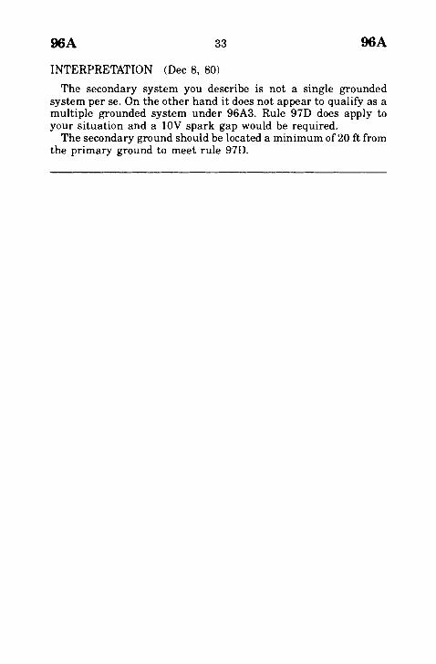
INTERPRETATION (Dec 8, 80)
The secondary system you describe is not a single groundedsystem per see On the other hand it does not appear to qualify as amultiple grounded system under 96A3. Rule 97D does apply toyour situation and a 10V spark gap would be required.The secondary ground should be located a minimum of 20 ft from
the primary ground to meet rule 97D.
110A 34 110A
Rules for the Installation and Maintenance ofElectrical Supply Stations and Equipment
Part I110A
(Sections 10-19)
Meaning to be attached to ~~prevent" in connectionwith equipment enclosures.
REQUEST (Aug 18, 80) IR 276Request is hereby made for interpretation of the above-re-
ferenced rule which provides, in part: ~~Rooms and spaces in whichelectrical supply conductors or equipment are installed shall be soarranged with fences, screens, partitions or walls as to prevententrance of unauthorized persons or interference by them withequipment inside. Entrances not under observation of an author-ized attendant shall be kept locked. Warning signs shall bedisplayed at entrances."The word «prevent" used in the above rule is a strong term which
seems to imply an absolute duty on the utility company. However,the rule goes on to provide: «Metal fences, when used to encloseelectrical supply stations having energized electrical conductors orequipment that can be reached by trespassers, shall be a minimumof seven ft in height and shall be effectively grounded. Other typesofconstruction, such as nonmetallic material, shall present equiva-lent barriers to climbing or other unauthorized entry."Here, the requirement that nonmetallic fences be constructed to
«present equivalent barriers" rather than ~~prevent" climbing orother unauthorized entry, implies a duty to impede rather than toprevent unauthorized entry.Since it would be impossible to prevent entry into fenced or fully
enclosed electrical supply stations if enough effort is put intopenetrating protective measures, it seems to us that the word«prevent" in the context of this rule is not intended to apply tointentional forcible entry.We request an interpretation on the duty of an electric utility to
en( ~ose equipment for the purpose of creating a barrier to un-authorized entry.
INTERPRETATION (Nov 11, 80)The word ~~prevent" as used in rule 110A is not intended to imply
that intentional or forced entry must be stopped. You are quitecorrect in stating that it would be impossible to prevent entry intofenced or enclosed supply stations if sufficient effort is put intocircumventing the protective measures.

124A Table 2
124A Table 2
35 124A Table 2
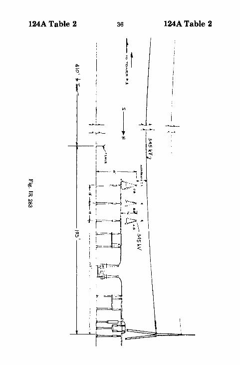
Clearance at crossing between transmission line andrigid bus structure
REQUEST (Dec 8, 80) IR 283
... presently installing a 345/69kV switchyard at ... GeneratingStation .... There are three (3) 345kV lines leaving the switchyardon the south side. The takeoff structures for these lines are located193 ft north of the south fence line. The first transmission towersare located 410 ft south of the fence line. An east to west 345kVrigid bus, possibility of another circuit, is located 117 ft (A phase),135 ft (B phase) and 153 ft (C phase) south of the takeoff structureand under the three 345kV transmission lines (see Fig IR 283).What is the required clearance between the transmission lines andthe rigid bus?Our opinion is that in the absence of specific rules in Part 1
which would conflict, and since the major portion of the span inquestion is outside of the fence of the substation, that Rule 233 ofPart 2 applies and that the required clearance is 14.66 ft at ourmaximum design conductor temperature of 176°F. The low point inthe downhill span is located over "C" phase of the rigid bus in the3ubstation.The following is the design criteria used:Transmission Lines
Conductor:Design Temperature:Span Length:Tension:
2-954 Kcmil ACSR per phase176°F603 ft8000# per phase
An outgoing 345kV transmission circuit is perpendicular to, andcrosses over, a 345kV rigid bus in a substation. This bus may not beof the same circuit. The major portion of the span, which rises to ahigher elevation on another structure outside of the substationarea, is outside of the substation fence. Is the clearance requiredbetween this outgoing feeder and the rigid bus in the stationcovered by Part 1 of the National Electrical Safety Code? If not,where is it covered by the Code and what clearance is required atfinal sag and at a conductor temperature of 176°F?
l/)
1
124A Table 2 36 124A Table 2

124A Table 2 37 124A Table 2
INTERPRETATION (Mar 18, 81)
Part 1 of the Code does not specify the clearance requirementsbetween conductors of an outgoing 345kV transmission line andrigid buses in a generating station.Part 2 of the Code (Rule 233) may be used as a guide to
determine the clearance if desired. In the absence of switchingsurge information, the straight line method should be used. The60°F clearance would be the sum of 14.66 ft plus 75% of the midspan sag increase incurred between 60°F and 176°F. The 176°Fclearance of14.66 ft meets the requirements ofRule 233. Given theswitching surge for the line, Table 233-2 might provide a some-what lesser clearance.

141
141
38 141
Definition of unsealed jars and tanks
REQUEST (Jan 17, 79) IR 244... [provide] an interpretation or definition of the term ((unsealed
jars and tanks" as referred to in Rule 141, Section 14, of theNational Electrical Safety Code.Section 14 on Storage Batteries in Rule 141, Locations, states:
"Storage batteries shall be so located as to be accessible only toproperly qualified persons. Separate battery rooms shall be re-quired only for unsealed jars and tanks."A previous edition of the Code defined two types of cell
construction in Section 13, Rule 130."The sealed type in which the only passage for the escape ofgases
from the interior of the cell is provided by a vent of effectivespray-trap design adapted to trap and return to the cell, particles ofliquid entrained in the escaping gases."If this is still the recognized interpretation, separate battery
rooms would not be required when modern enclosed batteriesequipped with vent plugs or explosion-resistant vents ... are used.
INTERPRETATION (Mar 14, 79)
Rule 141 does not require a separate room for sealed typebatteries. The description of sealed type batteries contained insubparagraph 1 of Rule 130, Part 1 of this Code (approved as anAmerican Standard May 8, 1941) is appropriate for application ofRule 141 of the 1977 Code.

153A2
153A2
39 153A2
Definition of "large", meaning of "segregated"
REQUEST (Dec 7, 78) IR 241... [concerning the] location of pad mount transformers in
proximity to building and areas accessible to the public, ... provide. . . an interpretation on a rule of the National Electrical SafetyCode. The rule in question is found in Section 15, Rule 153 A2.~Large oil-filled transformers should be segregated or protected bythe following methods, to minimize fire hazards." See also: IR244.What is the interpretation of ~large oil-filled transformers"?What is the interpretation of ~space separations"? Were actual
minimum distances considered as clearances from buildings?
INTERPRETATION (Jan 19, 79)
Pad mounted transformers in areas accessible to the generalpublic do not fallunder the jurisdiction of Part 1 of the Code. Part 1covers power generating stations, substations, etc. which areaccessible only to qualified personnel. Pad mounted transformersaccessible to the general public are covered under Part 3 of theNational Electrical Safety Code. However, Part 3 contains no ruleswhich deal with the specific hazard of fire involving oil-filledtransformers.

153Bl
153Bl
40 153Bl
Floor drains for transformer buildings. Meaning of"outside the building"
REQUEST (May 24, 78) IR 240In Part 1, Section 15, Rule 153B1 of the 1977 Edition of the
National Electric Safety Code, ANSI C2, when referring to indoortransformer installations, the code states ((Floor drains shall beprovided to carry oil to a safe location outside the building."Clarification is needed as to what is meant by outside of thebuilding. Attached is a standard used . . . in the locating of oilcontainment facilities in conjunction with indoor customer trans-former vaults. Please comment on whether or not each of the threeinstallations diagrammed meets code requirements.

153Bl 41 153Bl
NOTE:
(A) FLOOR TO BE SLOPED NOT LESS THAN 1;''' PER FOOT TOWARDDRAIN
(B) 6" MIN. REINFORCED CONCRETE WALL OR 8" MIN. BRICK WALL OR12" LOAD BEARING HOLLOW TILE WITH CEMENT PLASTER ON THEINSIDE
(C) JOSAM #253-A COMBINED TRAP AND DRAIN OR EQUIVALENT
(D) 2" DIA. PIPE THRU SLAB WITH FLUSH BRASS PLUG FOR PUMPINGOUT TANK
(E) CONCRETE OR BRICK DOOR SILL, MIN. HEIGHT 4"
(F) WEATHER PROOF VENT HOOD
(G) 3" DIA. DRAIN PIPE
(H) 2" DIA. PIPE THRU GROUND WITH BRASS CAP FOR PUMPING OUTTANK
(I) 3" DIA. DRAIN PIPE - PITCH 1;''' PER FOOT
(J) FLOOR SLAB: THICKNESS DEPENDING ON SUB-SOIL AND WEIGHTOF TRANSFORMERS
(K) LOCATION OF DRAIN, PIT AND TANK IN CENTER OF TRANSFORMERVAULT
(ll SIZE OF OIL PIT OR TANK 10% LARGER THAN OIL CAPACITY OFLARGEST SINGLE TRANSFORMER
(M) LOCATION OF OIL TANK UNDERGROUND OUTSIDE OF TRANS-FORMER VAULT
Fig IR 240-1

153Bl 42 153Bl

153Bl 43
r ----~
, rt II n (. ~r II I' ---1~.J'"r- Ii
rIIfl
"II11IIII11IIIIIf
H(eJ"r~w...o2
wCla
~Wt-oZ
153Bl
153Bl 44 153Bl
INTERPRETATION (Jan 22, 79)"We believe that each of the three designs meets the intent of
Rule 153Bl."

173B 45 173B
162 See 124A Table 2, IR 283
173B
Disconnecting provision acceptability
REQUEST (Nov 2, 79) IR 257
... request an official interpretation of Section 17, Article 173B,«Provisions for Disconnecting," of the 1977 National ElectricalSafety Code.Would a 600 A, 5 kV load break switch with provision for
padlocking, in either the open or closed position, satisfy the intentof the above paragraph?This switch is used to disconnect a 5 kV feeder to a medium-
voltage, drawout contactor type, motor starter. The contactor isboth mechanically and electrically interlocked so that the contac-tor cannot be drawn out unless the contactor is deenergized.
INTERPRETATION (Jan 14, 80)Rule 173B requires that remotely controlled switches, oil
switches and disconnectors be arranged so they can be secured inthe open position or plainly tagged to avoid inadvertent closing.Padlocking to keep a switch in the open position is an acceptablemeans of meeting this rule.

202A 46 202A
Safety Rules for the Installation and Maintenance ofOverhead Supply and Communication Lines
Part 2202A
(Sections 20-28)
(a) Distinction between Rule, Recommendation, Note,Exception(b) Requirements for guy insulator
REQUEST (Aug 29, 79) IR 254The question is the relative force of a Rule, or extent to which it
is mandatory, as opposed to the Exception frequently statedfollowing the statement of the Rule.In the 1973 Edition [of the National Electrical Safety Code], only
the differentiation between shall and should were provided,together with the significance of a Recommendation vs. a Rule.In addition, in the 1977 Edition, in a number of places the phrase
is used ~Notes contained herein are for information purposes ..." Iam particularly interested in an answer to this question relative tothe question of insulators in guys. In the 1973 Edition, Rule 283B1requires a guy insulator under the stated circumstances, while theExceptions that follo\\" negate this requirement. For example, is theuse of insulators preferred over grounding without the use ofinsulators? If the two alternatives are strictly at the installer'soption, why is the ~Rule" and ~Exception" format employed?A change in the 1977 Edition wording of Rule 283B1 now adds a
Note, which carries similar, but not identical wording to the 1973Edition. The term «need not be" has now in effect been substitutedfor the phrase~... are not required ..." which appears in the 1973Edition, Rule 283B4. May this change be interpreted asstrengthening the requirement for guy insulators?
INTERPRETATION (Oct 31, 79)
A rule is written to cover the general case and, for the describedcircumstances, is the governing requirement. Exceptions providefor specific conditions under which the rule is not applicable. It isnot the intent of the code to show a preference as to whetherexposed guys are to be equipped with insulators or effectivelygrounded. Code rules, including exceptions, have the force of lawwhere the code is adopted by the governing body of the state, city ormunicipality.

202B
202B
47 202B
Reconstruction definition. Does line voltage changefrom 7.2/12.5 kV to 14.4/24.9 kV require compliancewith 1977 Edition
REQUEST (Dec 17, 77) IR 219... request an interpretation of Section 202B on page 106 in the
1977 Edition of the National Electrical Safety Code. The specificquestion on interpretation involves existing line designed for7.2/12.5 kV operation to be re-insulated for 14.4/24.9 kV operation.Section 202B, «Application of Rules", states under 202Bl, ((These
rules shall apply to all new installations, reconstructions, andextensions except ...". Section 202B states under 202B2, «Existinginstallations, including maintenance replacements, which complywith prior editions of this code need not be modified to comply ...".At the present time, many electrical distribution systems are
converting from 7.2/12.5 kV to 14.4/24.9 kV operating voltage.Both of these voltage levels fall within the 0 to 15K phase toground voltage category in the Code. The required clearances arethe same for each voltage. To convert from 7.2/12.5 kV operation to14.4/24.9 kV operation simply requires replacement of existinginsulators with units having a higher insulation level. Any polechangeouts or other material replacement certainly can be consid-ered maintenance as they are not required by the voltage change,even though they may be accomplished at the same time. Theattached drawings from the REA specifications show that, typi-cally, the insulators and possibly the insulator pins are the onlydifference between the 7.2/12.5 kV and the 14.4/24.9 kV configura-tions.Therefore, our question is, does the replacement of 7.2/12.5 kV
insulation constitute reconstruction and therefore require the lineto meet the 1977 code requirements.

202B 48 202B
I I :I ~:I ~_
-E@J= ~'-0- - -. 1-- - ---0I I I
I ~ :,P LAN
III~-II
I 3'" " I
1
...~-...Il.\P4I._---=.-31_-_4'_1_~__. __._~ '---~-.J
¥b i- ~-_-=---r--_--i~Vk- c-d O~....~I . f~ I '-,.~ II /'II I - 1m C"d,,__ I //1 ~-a--: T-
1 --v--- --~
Guy when
Note:Th i~ con::t f r uc t ion (v qui r " dfor 1.111 conductors rh.l'f'i'li,) abrc:okirH..; ::.tranQth ot .-n~(c
thon 4500 pounds
Fig IR 219

202B
REQUEST (Jan 18, 78)
49 202B
IR 220
In the opinion of the Committee on Interpretations, are theconditions of application described hereafter considered ttrecon-struction" and therefore apply under Rule 202B1 or are theyconsidered ttordinary maintenance" and therefore apply under Rule202B2? The basic issue is whether or not a request and a grantingof waiver from the proper administrative authority is required ifduring the line modification the conductor clearances are not to bebrought up to conformance with clearance requirements of Part 2of ANSI C2-1977.
Description of existing linesThe lines in question consist of 7.2 kV single phase 7.2/12.5 kV
multiphase overhead grounded neutral distribution lines.The lines are located in rural areas, across ttother land" per Item
4, Table 232-1, Rule 232, ANSI C2-1977, or on such land butadjacent to ttroad rights-of-way" or with poles located within publicttroad rights-of-way" but with line conductors overhanging privatettother land".The lines were constructed during periods when the 4th, 5th', and
6th National Electrical Safety Codes were in effect. The clearancesare generally equal to or exceed clearance requirements for ttalongand within limits of road rights-of-way" per Rule 232A, and Table Iof the superseded Codes, but in many cases do not meet the ttotherland" clearance requirements per Rule 232 ANSI C2-1977.It must be assumed the original designers considered such
clearances in conformance with general requirements of Rules200C, 210 and 211 for there is essentially no existing evidencecontained on easements or other documents to indicate any specificclearance requirements were agreed upon with the land owners.
Condition of application Case 1To increase capacity without reconductoring, it is proposed to
convert said lines from 7.2 kV to 14.4 kV single-phase or from7.2/12.5 kV to 14.4/24.9 kV multiphase.The required line modifications consist of replacing insulators,
distribution transformers, fuse cutouts, surge arresters, reclosers,etc. as required for the new voltage level. It is generally notintended to replace poles unless otherwise required by deteriora-tion.

202B 50 202B
Condition of application Case 2In this specific application the lines were designed with pole
strengths as required for 3-phase lines, however, only one or two ofthe phase conductors are now installed.To increase capacity it is now proposed to add conductor or
conductors to convert the line to 3-phase operation.The required line modifications consist of addition of phase
conductors, insulators, etc., and in some cases, cross arms. It isgenerally not intended to replace poles unless otherwise requiredby deterioration.
Inquirer's interpretationThe writer concedes in some cases, conformance to the clearances
required for the "other land" requirements per Rule 232, ANSIC2-1977, may be impractical, and may impose an unfair economicburden on the utility which will in turn. be .passed on to theirconsumers.At the same time, by our own strict interpretation of ANSI
C2-1977, we can not construe the modifications in either Case 1 orCase 2 above to be. "ordinary maintenance", and therefore must beconsidered to fall under the category "reconstruction" as defined onpage 100 of ANSI C2..1977.By Rule 202Bl, it is mandatory that the rules of ANSI C2-1977
be applied for "reconstruction" except where waived by the properadministrative authority.While in some cases we believe that a waiver is justified and
should be requested, it is our opinion it was the intent of the CodeCommittee, that the determination ofjustification for waiver is theprerogative of the proper local administrative authority.We therefore believe, .asprofessional cOllsulting engineers, we
would be in error by making any recommendations other than theutility reconstruct in conformance with the 1977 Code or request awaiver from their state commission or other proper administrativeauthority.The writer has expressed this opinion to a number of clients and
at seven seminars on the 1977 National Electrical Safety Codeeither as a speaker or panelist. It has come to our attention thatthis opinion is being challenged by some engineers. We thereforebelieve it is in order to request an opinion from the ANSICommittee on Interpretation.

202B 51 202B
a"a" 3'-4" 3' .. 4"~ ~. I
I I I I" 1 ' I
II ~~:lP' II~"U--~~O--==- =-~---~--+/1--°----$3
~I II ek ,.- I I II I I"Neutrol IPLAN I
oI..
N Posit ion of Gu yI c-d when requirtH1
I _~ (bS--) ~-d I 'Note:
: \ This construction requi red for allcondu~tors having a breakillfJ strength
I 'of more than 4500 pound s.I II II II II Il:.~... j
Fig IR 220
202B 52 202B
INTERPRETATION (May 9, 78)
The Interpretations Committee has carefully considered yourquestion but has been unable to reach a consensus. Part of thecommittee believes that raising the voltage does not constitutereconstruction unless it is accompanied by an increase in themechanical loading on the pole. Another view is that with everypole being worked on to change insulators and all transformers,capacitors, cutouts, etc., being replaced, this is more than meremaintenance. We are sorry we are unable to provide a clear-cutanswer at this time; if the committee does reach agreement, weshall advise you accordingly.
NESC Secretariat Note. See 1981 Edition NESC Section I, Rule013B2

202B 53
* * * *
202B
Definition of reconstruction.
REQUEST (Apr 5, 78) IR 230
... have 12 mi of existing V¢ or two-phase line that we wish toconvert to 3¢ or three-phase. This would require the addition of onemore phase wire. The poles are already framed for three phase. Thepoles vary in length from 30 ft to 40 ft. The addition of the phasewire will not affect existing clearance ... Will this be consideredreconstruction when phase wire is added? ...
INTERPRETATION (July 6, 78)
Adding a third phase wire to an existing line is not consideredreconstruction; it would be considered a new installation or anextension of the phase.
NESC Secretariat Note. See 1981 Edition NESC Section I, Rule013B2
* * * *
New installations, reconstruction, extensions; status ofexisting installation if cable TV is added
REQUEST (Feb 16, 79) IR 243
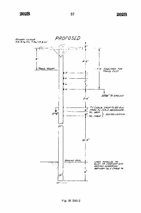
... Company X desires to find out whether the attachment to itselectric utility poles of certain cable television facilities, includingcables, wires, supporting strand, brackets, drop wires, tap-offs, lineamplifiers and related equipment, would constitute a «new instal-lation, reconstruction, or extension" under Rule 202B, such thatthe increased overhead clearance requirements (under 1977 codeamendments) of 22 ft for ... electric lines crossing over roads,streets, and alleys subject to truck traffic, would apply. . . .currently has in excess of 50 000 utility poles of 35 ft length whichconform to the clearance provisions of the 1975 edition of the codeby allowing not less than 18 ft of clearance from the center of anyroad, street, alley or parking lot subject to truck traffic. Because ofvarious constraints, the 22 ft clearance required in the 1977amendment to the code cannot be obtained without replacement ofthe 35 ft poles by 40 ft poles. In the due course of installations,reconstructions and extensions of X electrical facilities, X has been

202B 54 202B
and is replacing the shorter poles with taller ones and is conform-ing clearances to the 22 ft requirement. However, there has beenno effort to accomplish this conversion in wholesale fashion over ashort period of time, nor is manpower available for such ashort-term conversion.X has recently entered into a pole license agreement with a
corporation which is engaged in providing cable television servicesto ... residents. That agreement grants Company Y the right toattach its facilities to X poles, where such use will not interferewith X service requirements or others' use. The parties under-stand, and Y has agreed under the contract, that its cable facilitieswill comply with the clearance requirements of the code ascurrently amended and as applicable to communication facilities,and there is no question being raised here as to the applicability ofthe current rules to the cable facilities. X is concerned only withthe compliance status of its own electrical facilities, but neither ofthe parties to the contract is desirous of undertaking the wholesalereplacement of 50 000 utility poles. To clarify that no such massreplacement is required under the code, X is seeking an interpreta-tion that the attachment of the cable television facilities is not a«new installation, reconstruction, or extension" which would trig-ger compliance with the new clearance standards for the Xelectrical facilities which are already in place on the poles.X believes that there are a number of reasons why attachment of
the cable facilities does not constitute such a «new installation,reconstruction or extension." The cable facilities will themselvescomply with current clearance provisions of the code, and theirinstallation clearly is not an extension or reconstruction of theexisting electrical facilities which are in place, nor do theyconstitute a new electrical installation or one which will requiresignificant alteration of the in-place electrical facilities. Logically,the new clearance provisions should apply when the electricalequipment itself is replaced, extended or·reconstructed, but notwhen unrelated, complying facilities are attached.(1) Voltage of conductors?
(a) Telephone cable - 105 V ac ring 48 V dc talk.(b) CATV cable - 60 V ac.(c) Neutral - 0 V.(d) Secondary - 120 V ac line to ground and 240 V line to
line.(e) Primary - 7620 V ac phase to ground and 13 200 V ac
phase to phase.(2) The CATV cable has a continuous metallic sheath which is
grounded at each pole attachment point.

202B 55 202B
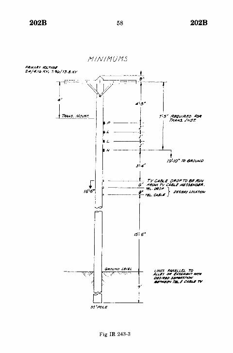
(3) Distance from grade to:(a) Telephone Cable - 15 ft midspan 16 ft 6 in at pole.(b) Neutral - 20 ft midspan 20 ft 10 in at pole.(c) Secondary - 21 ft midspan 21 ft 10 in at pole.(d) Primary - 27 ft midspan 29 ft at pole.These clearances do not constitute a violation of those recom-mended by the National Electrical Safety Code; However,Texas Case Law requires that the neutral be treated as anenergized phase conductor. The question you are being askedto resolve is, ~~does the addition of CATV cable and appur-tenance, with no revision of electric facilities, constitute achange such that the pole should be reconstructed with theincreased clearances specified in the 1977 National ElectricalSafety Code?" Since Texas treats the neutral as a phaseconductor, this would require for new installations, raising theneutral from 20 ft to 22 ft above grade for lines crossing publicroads, streets, alleys, and parking lots subject to truck traffic.
(4) Drawings of a present pole (Fig IR 243-1), a proposed pole (FigIR 243-2), and a minimum clearance pole (Fig IR 243-3) follow.Fig IR 243-1 illustrates the dimensions given in the answer toitem 3. Fig IR 243-2 shows the dimensions which would coverthe majority of the 35 ft poles in our system, and these are asfollows: From Grade to:(b) CATV Cable - 17 ft 6 in at pole.(c) Neutral - 20 ft 10 in at pole.(d) Secondary - 21 ft 10 in at pole.(e) Primary - 20 ft at pole.Fig IR 243-3 shows the absolute minimum clearance forconductors from ground on a 35 ft pole only along alleys oreasements and these are as follows:From grade to:(a) Telephone Cable - 15 ft 6 in at pole.(b) CATV Cable - 16 ft 6 in at pole.(c) Neutral - 19 ft 10 in at pole.(d) Secondary - 20 ft 10 in at pole.(e) Primary - 28 ft at pole.

202B 56 202B
7~~)' Rc~t//,qe(J .&"O,'fTA'~..v-.t fNS l:
20'-/0"TO 6ROt/A/iJ
-- TEl.. CAll.E
f6!..6"
""L·'-o
A~i.~Y ,,~ t'/ScM~A17WITH~~.1/!1NJ sG.#e~~rIOA/
411'W1.1'N T4.1 &'.441..1 7"JI
_L
Fig IR 243-1
202B 57 202B
7~5" REQ(.//RcD ~a~
TR.4A~ INS!:
PR,MAIl'l l~ r~.5e-
7.4/4. '" KV, 7. 9t1/ '3.8 KV
~o'!Jo" TO 6RO(./A/O
PROPOSED__ ._- __._ _ ._ t _
-r:=--=7'~~:G;~-""-'~c::~~]r.4'-5"
Ip ----t-
,/'----~I-
j'L ----~
IV ---1-'---,j'-4'
/6!.6"
"\'1. ".
GROl.IlVtJ LEVE/.~~.-.~ LINES PARALLEL TO
Au.£-)' O~ &.~SEA(EN'TWlrN"~.1/IlR'" S~peA',4rlo.4,/
4~n~;:~NT~t..1 CA4J.5 TV
Fig IR 243-2
202B 58
I1INII1UI1S
r16'-£t'
/5!.6"
GIlO(/N[) L4V61.
202B
LINE'S PARALLEL roAU.I)' air 4'~UM.4W7JW1'N"~,JI"'NJ ~A~
6I"W11!Wm.1 ~MN.I"'
o ._L
Fig IR 243-3

202B 59
INTERPRETATION (Mar 14, 79)
202B
Addition of communication facilities to an existing jointly usedline does not affect the ground clearance requirements for theelectric power facilities. However, clearances between the addedcommunications facility and the electric power facility must meetthe requirements of Rule 235, (essentially the same requirementsin the 1977 and 1973 Codes). Also, the line would have to meet thestrength requirements of Rule 261 after the addition of thecommunication facilities.

202Bl
202BI
60 202Bl
Meaning of ~~reconstruction"
REQUEST (Dec 12, 77) IR 215
... We have need for knowing the definition and meaning of theword "Reconstructions" as used in Part 2, Rule 202B1 of the 1977Edition of the National Electrical Safety Code. Upon studying theusage of the word ~~reconstruction"we find several definitions areused in the industry.We have electric cooperatives that have been installing single
phase overhead lines and have provided pole strength for futureconversion to two or three phase where their long range planningdetermined multiphases would be required at a later date.We would appreciate clarification of the intent and application of.
Rule 202. Do incidents involving replacement of facilities resultingfrom storm damage rebuilding constitute maintenance? Doesnormal pole replacement constitute maintenance?
INTERPRETATION (Mar 13, 78)
Replacement in kind regardless of the reason, is generallyconsidered maintenance; replacement with stronger, larger ortaller units is generally considered reconstruction. Maintenancereplacements are not considered reconstruction.
NESC Secretariat Note. See 1981 Edition NESC Section I, Rule013B2

214A2
214A2
61 214A2
Frequency of inspection for service drops
REQUEST (Feb 5, 79) IR 246
Using the data supplied on the attached sketch, please advisewhether or not an interpretation can be rendered regarding thefrequency with which the service drop span should be in-spected....This particular 500 MCM four-wire, delta service drop is 75 ft
long and spans from a wooden utility pole to a mast at the rear of arestaurant, with all of the output of the transformers being solelyfor the purpose of supplying power to the restaurant. The servicedrop span operates at 240 V delta with a center tap on one phase toprovide 120 V for lighting and receptacles and small appliances.This installation exists in an urban area on the mid-Atlantic coastwith the ocean a few blocks to the east and is subject to occasionalhurricane force winds and temperatures ranging from below zeroto 100°F.The service drop is easily visible from vehicles passing by on the
street and the utility pole is at the sidewalk.If there are no specific rules or known minimum standards for
the frequency at which such an installation should be inspectedand any defects recorded and/or acted upon, can you then advisewhat the general consensus is within the electric utility industrywith regard to customary acceptable procedures and practices forsystematic inspection of service drop installations such as the onepictured on the attached sketch.

214A2 62 214A2
< NORTH
URBANAREA
Yearly temperature range'- I O'~ F to +I 0 O()F
Subject to hurricane \.. innsand salt spray
STREET RESTAURANT ParkingLot
Parking lot
Transformf'rs on polf's e' rving rt'staurant anI y.Total capacity of bank is
167 kVA.
Mast on bUilding,
J, ~f'te'ro location
:;00 MCM Al40 V. \.. ith
(" (·ntt·r tap ononC' phas('
~
Fig IR 246

214A2 63 214A2
INTERPRETATION (Apr 10, 79)
Rule 214A2 states that inspection should be at such intervals asexperience has shown to be necessary. The ~experience' referred toin the rule means, in general, the experience of the utilityinvolved. The National Electrical Safety Code does not specify thefixed period of time, and the Interpretations Subcommittee cannotprovide a specific answer.
215Cl
215Cl
64 215Cl
(a) Magnitude limit of ground fault voltage. (b) intent of~~effectivelygrounded" as applied to structures.
REQUEST (Feb 23, 78) IR 227Referring to ANSI C2, 1977 Edition, National Electrical Safety
Code: Page 107, Part 215: Grounding shall be in accordance withapplicable methods given in Section 9. 215C1: ... Supportingstructures ... shall be effectively grounded. Page 102, Definition:supporting structure.What is the intent of the meaning or definition of effectively
grounded?IEEE Std 100-1972, Dictionary of Electrical and Electronics
Terms, defines:effectively grounded. Grounded through grounding connec-tion of sufficiently low impedance (inherent or inherentlyadded or both) that ground faults that may occur cannot buildup voltages in excess of limits established for apparatus,circuits, or systems so grounded.
Who or what authority determines the limits of the ground faultvoltages established for apparatus, circuits, or systems sogrounded?Do you agree, that this means that metal supporting structures
are to be grounded so that voltage due to ground faults on thestructure cannot build up to a value which is lethal? Consider thatyou do specify limiting maximum tolerable voltage differences forSupply Stations according to your Rule 96A1.
INTERPRETATION (June 16, 78)You are raising questions which relate to a definition contained
in the IEEE Dictionary. Such questions should be referred to theresponsible committee (C-42). For purposes of the National Electri-cal Safety Code, the term ~(effectivelygrounded" is defined on Page99 of the Definitions Section in the 1977 Edition. With respect tothe touch-and-step voltage formulas contained in Rule 96A1,please note that these are not mandatory; they are recommenda-tions and are stated as such.
See also Rule 94A3
220B2 65
215C2 See 283A3, IR 236
220B2
220B2
Clearance requirements for CATV amplifier powerfeed
REQUEST (Oct 15, 79) IR 255... [Fig IR 255 below] ... shows a typical arrangement of power
line conductors, cable television, and telephone facilities on acommon use pole. The 120 V power lead for the transistorizedamplifier power tap is dimensioned as 12 in minimum between thispower lead and the telephone cable below. Is this 120 V power leada line conductor, a communications line, a vertical conductor, or alateral conductor?If the 120 V power lead is interpreted to be a line conductor, the
required minimum clearance would be 40 in as specified in Table235-5, column 1, line 1, or 16 in if the telephone and cabletelevision companies comply with Rule 220B2.The definition of a communication line allows power supply
conductors to be included under specified conditions. If the 120 Vpower lead is interpreted to be a communication line, are thesespecified conditions limited to those in the definition of a communi-cation line or do they include Rule 220B2? Does Rule 235G apply tothis situation if the 120 V power lead is interpreted to be acommunications line? If so, the minimum clearance between the120 V power lead and the telephone cable is 4 in.If the 120 V power lead is interpreted to be a vertical or lateral
conductor, Rule 235E, Table 235-6, permits 3 in between acommunications line conductor and a vertical or lateral conductor.

220B2 66 220B2
JOINT POWER, TELEPHONE AND TV POLETELEVISION EQUIPMENT POLES
TYPICAL ARRANGEMENTS
'2'''0'' Min.
FUll' di,conn.ctor eQulval.nt
Pol.IlitH-+-~---""Moun"nt
Broe_et
r:::u~torI cabl'
40.... in.Tron'i'tOrilld~ampllfi.r ! Ipow,r top II. 12" .1. 12" .1 I
"
j ~ I'
Ei~:;;::=~/~=iOtlr:! I !~_~.~Tiii,,~coiiiib="==
_~iiiii.tiliilfli~EiI.1 Il~·.•TjI!'.".Pmh°Bn~,~ciilioiilblli\i'iifii. III 'III T".p4\on,I Company
i' '! II~I_,t:iiiItii:::.;diiiii:, II: t
III!Id
Connection to b. mod,b, Pow,r Compont
liz" p'astlc con.ult (Mar' ..[Trion," Conduit a Cabl.Cable Co. ) or equiu'tnt.
DETAILS OF POWER SUPPLY TO CATVCABLE SYSTEM SERVICE 'MOUNTINGUSING 1001 POWER SUPPLY HOUSING
Fig IR 255

220B2 67 220B2
INTERPRETATION (Dec 20, 79)
The small cable extending from the vertical run on the pole tothe CATV amplifier is best described as a communications jumper.It is not a line conductor; neither is it a vertical nor lateralconductor. It follows that the vertical run to which it is connected isa communications facility.We understand that this jumper carries 60V ac and is current
limited, rather than 120V ac as originally indicated. There is noprescribed clearance between communication cables and jumpers.Rule 220B2 was intended to cover special power supply arrange-
ments used in the operation of certain railroad communicationssystems. It was not visualized that these kinds of installationswould have other applications. Communication facilities shouldoperate within the limitations of the definition; Rule 220B2 is anexception for a special situation.Rule 235G applies to line conductors on vertical racks. It does not
apply to jumpers such as the one from the amplifier to the pole.Note that table 235-6 applies to open wire. It does not apply to thejumper partly because the jumper is neither vertical nor a lateralconductor and partly because the jumper is a fully-insulated cable.

230C
230C
68 230C
Clearance for aerial secondary and service conductorswith an insulated neutral
REQUEST (Sept 4, 80) IR 279We use high density Polyethelene (HDPE) insulated triplex and
quadruplex cable with an HDPE insulated neutral for our aerialsecondary and service conductors. These cables are operated below600 V and do not have metalic shielding. The effectively groundedneutral is an all aluminum alloy conductor which also serves as thesupporting messenger. Much of our service area is located in anarea of high contamination and the insulated neutral providessome mechanical and corrosive protection.We would like an interpretation of Rule 230C, National Electri-
cal Safety Code, ANSI C2, 1977 Edition as it would apply to supplycables with insulated messengers. Since all three categories ofRule 230C specifically state the grounded messenger is bare, canwe consider our supply cable as conforming to Rule 230C forclearance purposes?
INTERPRETATION (Nov 19, 80)
The supply cable you describe cannot be considered as meetingRule 230C because the neutral is not bare. For clearance purposes,the cable would be treated as open conductors and column 2 ofTable 232-1 would apply for voltages below 750 V.

231B
231 B
69 231B
Location of pad-mounted equipment
REQUEST (Nov 6, 79) IR 258
In reference to the 1977 Editon of the National Electrical SafetyCode, ... [please provide) ... a clarification with respect to thelocations of pad-mounted equipment.In Part 3, the code makes no mention of any physical locations in
relationship to streets, roads and highways. Part 2, Rule 231Bstates a specific distance from the street side of the curb tooverhead equipment supports. Does this rule also apply to pad-mounted equipment in underground systems? If not, what is therecommended distance?
INTERPRETATION (Dec 21, 79)
Rule 231B does not apply to pad-mount installation. Rules 300,310 and 311 apply but do not specify a definite distance.

231Bla
231Bla
Example requested
REQUEST (Apr 6, 78)
70 231Bla
IR 231aPlease furnish an interpretation as to when Rule 231B1a of the
1977 Edition of the National Electric Code would apply.
* * * *REQUEST (Apr 11, 78) IR 231b. . . request your assistance in interpreting several specific
requirements of the 1977 Edition of the National Electrical SafetyCode. Rule 231BlaUnder what condition would the 6 in setback apply, since weinterpret one ft is required on all local streets and roads, and a 2ft setback is required on all arterial roads?
INTERPRETATION (July 7, 78)
Rule 231B1a was inadvertently altered during the printing andediting of the book. As approved by letter ballot of the C-2committee, this rules reads as follows:B. From Streets, Roads, and Highways
1. Where there are curbs, the measurement from the streetside of the curb to the supporting structure, support armsand equipment attached thereto up to 15 ft above theroad surface:a. shall not be less than 6 in.b. should be not less than 2 ft on arterials which are
primarily for through traffic, usually on a continu-ous route.
c. should be not less than 1 ft on local streets androads which are primarily for access to residences,businesses, or other abutting properties.
232 Table 232-1
232 Table 232-1
71 232 Table 232-1
Ground clearance for service
REQUEST (Aug 25, 80) IR 277. . . presently staking distribution lines that will provide
electrical service to numerous cathodic protection stations. Theseinstallations are served with 120/240 V service from a primarytransformer pole which will be provided by the Cooperative and ameter pole which is provided by the customer.A question has arisen concerning the intended height for service
wires to these installations.

232 Table 232-1
-- .---:-~i -.:. J +
72
Fig IR 277
232 Table 232-1

232 Table 232-1 73 232 Table 232-1
INTERPRETATION (Nov 11, 80)
The circumstances described in your letter and [in Fig IR 277above] indicate this installation falls in category 4 of Table 232-1.That is, the required clearance in both zone ttA" and zone ttB" is 18ft at 60°F no wind.

232A Table 232-1
232A Table 232-1
74 232A Table 232-1
Service drops; clearance to ground
REQUEST (Feb 7, 78) IR 223
This rule requires 15 ft basic clearance with provisons ofreduction of clearance to 12 and 10 ft.The following are types of services which we are concerned with
in relation to overhead service drops from the utility company'spower pole to the consumer's building:(1) 240/120 V, three-wire, single-phase.(2) 208/120 V, four-wire wye, three-phasse.(3) 480/277 V, four-wire wye, three-phase.(4) (a) 240 V, three-wire, corner grounded delta, three-phase.
(b) 240 V, four-wire delta, three-phase.(5) (a) 480 V, three-wire, corner grounded delta, three-phase.
(b) 480 V, four-wire delta, three-phase.What type of services were intended to fall under Note 8a and
8b? More directly, the following are areas involving Note 8 whichwe would like clarified in relation to the above mentioned services:(A) What is meant by the statement in Note 8a, ~~Supply
conductors limited to 300 V to ground"? Example: does 1, 2, 3, 4a,4b fall in the category?(B) What is meant by the statement in Note 8b, ~~Supply
conductors limited to 150 V to ground"? Example: does 1,2, 4b fallin this category, or does it simply mean two wire services from 1and 2 above?(C) Is it the intent of Note 8b that all services which fall under
this category and attach to the electric service entrance of thebuilding, may reduce the required minimum clearance (15 ft) to 10ft, or does it mean that the attachment height of the service can be10 ft, thereby allowing even less clearance due to sag in the cable?
INTERPRETATION (Apr 10, 78)(A) Supply Conductors limited to 300 V to ground include the
following:240/120 V three-wire single-phase208/120 V four-wire wye three-phase480/277 V four-wire wye three-phase if the neutral is grounded240 V delta, three-wire or four-wire, grounded or not(B) Supply conductors limited to 150 V to ground include the
following:

232A Table 232-1 75 232A Table 232-1
240/120 V three-wire single-phase mid-point grounded208/120 V four-wire wye three-phase grounded neutralThis is not restricted to two-wire services.Voltage to ground of grounded circuits is defined on page 103 in
the definitions.(C) Footnote 8b of Table 232-1 refers to the clearance at the
building; it does not allow a lesser clearance anywhere else in thespan.

232A Table 232-1 76
* * * *
232A Table 232-1
Clearance over residential driveways
REQUEST (Jan 26, 78) IR 224
Your interpretation is requested as to the intent of Item 3 inTable 232-1. Is this item meant to apply to all residentialdriveways irrespective of their potential for ((truck traffic" orshould clearances for residential driveways with such potential beconsidered as shown in Item 2, ((Road, Streets, Alleys, Parking LotsSubject to Truck Traffic," or Item 4, ((Other Land Traversed ByVehicles Such as Cultivated, Grazing, Forest, Orchard, Etc."?Our specific concern is that vehicles such as motor homes, pickup
trucks with campers, moving vans, etc., often exceed the Note 23guideline which considers a truck to be any vehicle in excess of 8feet in height and thus can be reasonably anticipated in mostresidential driveways.
INTERPRETATION (May 8,78)
Item 3 of Table 232..1 applies to all residential driveways,regardless of the fact that there might be at some time or other acamper, van, etc., in the driveway. In Table 232-1, Item 3, the leftcolumn should read ((residential driveways, and commercial areasnot subject to truck traffic."
INTERPRETATION (July 25, 80)Based upon your description of the area and the traffic count
accompanying it, the locale in question must be considered urban.The required 60°F clearance for the installation is 18 ft.
* * * *
Effect of trees on minimum clearance
REQUEST (Nov 2, 79) IR 256
Please provide the interpretation of the following rule of theNational Electrical Safety Code, ANSI C2, Section 232, VerticalClearance of Wires, Conductors, Cables, and Live Parts of Equip-ment Above Ground, Rails, or Water.With reference to this Section, does the presence of trees affect
the minimum clearances stated in Table 232-1?

232A Table 232-1 77 232A Table 232-1
INTERPRETATION (Dec 20, 79)
The presence of trees does not affect the clearances stated inTable 232-1. Rule 281A calls for trimming where trees mayinterfere with supply conductors, but it does not specify safeclearances.
* * * *
Clearance over snow covered ground
REQUEST (June 25, 80) IR 270
... currently designing a 345 kV line in the high mountaincountry where the snow cover can reach a depth of almost 15 ft.Since the National Electrical Safety Code, 77th Edition, Rule 232,does not specify any special requirements for this condition, wewould appreciate any recommendations on this clearance problem.
INTERPRETATION (Sept 30, 80)
The Code does not specifically address the question of clearanceswhere snow accumulation in the vicinity of supply lines may besignificant. Rules 200, 210 and 211 do, however, provide somegeneral requirements.
* * * *
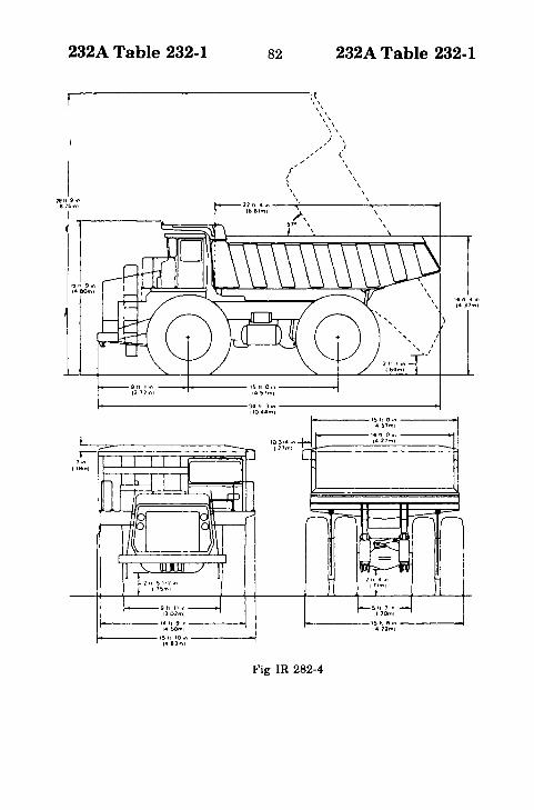
Clearance for oversize haulage trucks
REQUEST (Oct 17, 80) IR 282
. . . would like clarification of the proper vertical clearanceminimum requirements for truck haulage routes. The only relatedrequirement in ANSI C2 is Table 232-1, item 2, ffRoads, streets,alleys, parking lots subject to truck traffic." The minimum require-ments in item 2 are 18-22 ft, depending on the voltage level of thelines. Modern haulage trucks ranging from 22 ton to 350 tonpayloads have overall heights (with body down and empty) from 12ft to 30 ft. Obviously, use of the clearances listed in Table 232-1would present a hazard to operators of the larger haulage trucks., .. Realizing that no one general height could be satisfactory for
all truck sizes, ... wonder if you might recommend a vehicle heightplus for minimum clearance.

232A Table 232-1 78 232A Table 232-1
Another :;eparate but related matter of concern is the height ofpower lines located in close proximity to truck dump sites. As anexample, a dump point located approximately 100 ft from andparallel to power lines. The haulage trucks would back up passingunder the power lines enroute to the dump point. Because of thenearness of the power lines, it is imperative that the dump body befully lowered before any forward progress of the truck.. . . question is, would ANSI recommend any additional clearance
distance for power lines located in close proximity to sites wheretruck dump bodies are operated (see Figs IR 282-1-7 for vehicleheight examples).

232A Table 232-1 79 232A Table 232-1
I201171n,t27m,
1_-__- -~~~~~-- _ -- I
Fig IR 282-1
'1")"'lnIJ441111
,__ _ 10'II·n_i (3~1
_.11110." _(300m1
____ 10'12'I,ln_._<J\""I

232A Table 232-1 80 232A Table 232-1
7,n 10 11m)
I ~8lt.7Inl]62ml--1 I~12'1.!I.nIJ~m)~
~12f1~,n(3.'ml'hIPPt"9"'cllh~I l::==1111.7,n (3~1=:jI
Fig IR 282-2

232A Table 232-1 81 232A Table 232-1
r-141I-o,n (421m)lh,pp,nllw'dlh~
::::;::=:;::::::;:::::;:=:::;=;:::::;:::~::;::;·7';~1~..l".!t- 11:=::=1) 11 -0 ,n 14 07m)===:j1
"t-2In10&9ml
Fig IR 282-3
232A Table 232-1 82 232A Table 232-1
I1811 9 ,n1816m)
I
t~ II 9,n1480ml
~t
"\'"",\
\ ,1\/ ,
,,' J,,;''' <',/ "f \
< \, \" \, \
9 II I,n --......._---- I~ II O,n ------11217m) 14 ~7m,
...-------------34'. 3,n --------------1tl044m l
7r:-n==n==r=n~~~P1 18m)
1t------14 II 9 ,n ------114~ml
~----15" 10,n ------t(483m)
t-------I!l It 6,n ------.1412m)
Fig IR 282-4

232A Table 232-1 83 232A Table 232-1
2'" a..l.OOmI
t------------JI~~~~-----------4
1------ 21"OIlo ••.4Ooft1
...----- "" ... 11 .....'
'''7 ..•11Orft1
t------\~~:...~ ----~
Fig IR 282-5

232A Table 232-1 84 232A Table 232-1
lOOY WID'" 'T..1I II 11 n. '.P II
38 ft.-6ln.(11.74m)
t
i) Ie 1t.-3In
""\/ : I (U01
m)
L~A'~~2~n. : 3 't.·lln.(0.66 m) I (1.12 m)
-----l-- 12(~.;~%)in. ---1---------4
(\
\
\ GENERAL ARRANGEMENT(Dimensions For Empty Vehicle
Shown With BasIc Body)1\I\
18 't.·O In.(5."9m)
.. , ft.-l0 In.(1275m)
"70 IS PO IS 110U. IS '3 IS ... ,.... ':' '04 114' I"~72' Ft. '7 10'P
""'''' ""'''' 1511'1" ,." .... 111111".10 .23 .,. Slr.I ....
lltt.-7~ In.(S.88m)
""uel '.A.ICU"C YAIIOSCUIIC WUlIIS1,1 HIA" I.A LCUIIC YAROSCUI'C W(UASLOAOI~~f~·IQHT
WlUAS
2Oft.-5In.(6.22m)
20ft-"ln.(6.20m)17 'toO in.(S.18m)
Fig IR 282-6

232A Table 232-1 85 232A Table 232-1
GENE..AL A....ANGEMENT(Dimension. For Empty Vehicle)
.. ".~ In.(17.07 m)
I
IL' .......;>o._+----"~__
LI. 13".-lln._--+ _~_~.3Im)_
31 "-10.lln(11.2.m)
1I
I II "" "3 In.I (U7m)
I
, I
2 ".-4 lin."---f"""'+-+----+---~~~-(0.75 j) ~lo---1l-...4.-..I..--+-_-I...4--+-+--4-
1~:'~'~r' ---.J I I 17 ".-2 In.----J
L- 21 ""In. ----l I "------22~~~~.~~n.t-----2~~~~:~n. ---J (7.11 m,
(7.12 m) "Title dlmanelon II 'akan lor. loaded -"Ie...
,-----I
Fig IR 282-7

232A Table 232-1 86 232A Table 232-1
INTERPRETATION (Jan 14, 81)
The 1977 Edition of the Code does not specifically address thematter of clearance involving oversize trucks and supply lines.Some general guidance is contained in Sections 20 and 21. Notealso that footnote 17 associated with Table 232-1 does point outthat the clearances for surface category #4 are based upon anequipment or vehicle height of 14 ft. These clearances are the sameas for category #2 (Roads, streets, alleys, etc., subject to trucktraffic).A reasonable procedure (although not required by the code)
would be to increase the road crossing clearances ofTable 232-1 bythe difference between the height of the tallest truck in theoperating condition and 14 ft. Clearances involving situations suchas those you describe should be based on agreement between theutility and the organization that controls the haulage route andthe size of the trucks used.

232A Table 232-1 87
* * * *
232A Table 232-1
Conductor clearance for line near recreational waterarea
REQUEST (Oct 23, 79) IR 261... require ... a clear and accurate interpretation of the meaning
and intent of Item No.8 in Table 232-1 in the 1977 Edition of theNational Electrical Safety Code. Your comments relative to itsapplication are requested.We have an existing single phase, 7200 V electric distribution
line that runs parallel to and within 20 ft of a branch of Lake ...The energized conductor is bare wire as is its accompanyingmultigrounded neutral conductor. The line does not cross overwater. Fig. IR 261-1 below shows the physical location of thedistribution line in relation to its environment. Also attached is atable, Table B, which summarizes actual field measurements madethis summer of the vertical clearance of the neutral conductorabove the ground at the point of apparent minimum clearance.The National Electrical Safety Code (ANSI C2) Item 8, of Table
232-1, states (that where wires, etc., cross over) ((public or postedprivate land and water areas for rigging or launching sailboats" -((clearance above ground shall be 5 ft greater than in 7above...."The following information is pertinent to the investigation of
this problem:(1) This is private land, not public, but it is conceivable that the
general public could trespass and use this portion of beachfor miscellaneous purposes.
(2) The land in question is not posted in any manner. It could bein the future.
(3) By observation, this is not an apparent launching or riggingarea for sailboats, but because of its convenient location toboth a public road and water, it may be used for this purpose.
(4) It has been observed that this land area has been used for((beaching" sailboats and other water vehicles.
(5) A stringent interpretation and enforcement of this portion ofthe National Electrical Safety Code could cause ... electricutilities financial hardships because of the vast number ofinstallations similar to this one.
REA Bulletin 40-7, April 29, 1977, directs ... [the company] ...to comply to the National Electrical Safety Code. Our specificquestion is: Must this portion ofdistribution line (and similar ones)comply with Item 8 of Table 232-1?

TABLE
B~
(see
FigIR
261~1)
~ ~
Pole
Approx.
Approx.
Measured
Distanceto
Pt.
..-dsure
Approx.
>Height
Distance
Distance
Span
Measured
frOT
...elght-G
round
Height-Ground
~Pole
(ft)andto
Water'sDow
nGuy
(Between
Span
Immediate
PolL
toNeutral
toPrim
ary
=Num
ber
Class
Edge
(1)
toWater
Poles)
Length
toWest
Conductor
Conductor
(±4in)
cr ..... ~3
40~6
60ft
45ft
~ ~ ~ I4
35-6
55ft
40ft
3-4
335ft
210ft
25ft8in
29ft8in
~
535-6
10ft
None
4-5
258it
145ft
24ft4in
28ft4in
635-6
15ft
5ft
5-6
222ft
114ft
23ft7in
27ft7in
00 00
735-6
40ft
DNA
6-7
270ft
135ft
23ft4in
27ft4in
835-6
10ft
None
7-8
292it
156ft
23ft6in
27ft6in
~
935-6
6ft
None
8-9
298ft
156ft
22it7in
26it
7in
~ ~ >10
35-6
20ft
8ft
9-10
242ft
130ft
22it9in
26ft9in
~ =11
35-6
5ft
InWater
10~11
354ft
180ft
19ft8in
23ft8in
cr ..... ~11.1
35-6
·15ft
Oft
11~11.1
180ft
87ft
25ft
1in
29ft
1in
~ ~ ~
1235-6
5ft
InWater
11.1-12
192ft
80ft
24ft
10in
28ft
10in
I ~
(1)Asmeasuredon
August29,1979
(approx.
75°F,windSE
approx.10
mph).

232A Table 232-1
'--
89
SANDy:BEACH
h12'2-
Fig IR 261-1
232A Table 232-1
(!) UT,u'fl' POL.E.
--J D~~ Gu....'I. POLL ~\JM~~~
-- c..o~n\lc.TotG)

232A Table 232-1 90 232A Table 232-1
Fig IR 261-2

232A Table 232-1 91 232A Table 232-1
Fig IR 261-3

232A Table 232-1 92 232A Table 232-1
Fig IR 261-4

93
Fig IR 261-5

232A Table 232-1 94 232A Table 232-1
INTERPRETATION (Feb 15, 80)
In our view, the description of the land traversed by your linedoes not require the higher clearance specified by Item 8 of Table232A. Further, Rule 202B2 makes it clear that installations whichcomply with prior editions of the code need not be modified to meetthe requirements of the 1977 code.

232A Table 232-1 95
* * * *
232A Table 232-1
Communication cable clearance to ground
REQUEST (May 21, 80) IR 269
. . . communications cable runs along a two-lane blacktopentirely within city limits. The traffic on this road was observed fora three-hour period and found to be 162 vehicles (see enclosedtraffic analysis). Referring to the enclosed maps, we are concernedwith the two-block area (725 ft) of. . . . Street between the . . .service road and the canal. ... Street is not a through street as itdead ends at a boat launch (as shown on the larger map).The immediate area is lightly developed, mostly residential. It
appears that the vacant field is used as parking for . . . inn,although it is not designated as a parking area. The elevation ofthe field is 6 to 12 in higher than that of ... street, and there are noditches along the road. The posted speed limit is 20 mph.Does this fall within the 13 ft vertical clearance for roads in rural
districts as set out in Table 232-1, point 10, footnote 12, or is adifferent clearance required in this case?
Analysis of Traffic
[Specific date and time given]
Type of Vehicle
AutoSmall TrucksTractor Trailers
Total
Direction VehiclesWere Headed
North South48 3918 57o 0-- --66 96
Number of vehicles towing boat trailers-8Number of V-turns made in the area of the cable damage-3 (1auto & 2 small trucks)

232A Table 232-1 96 232A Table 232-1___.-J I l . . .-..------ ...-----
~ .$£r..t//l.t;- ;2tJ/lD
-----------1/\
[
LCL
Cr2:E
rsL--
~
L_I C~
EL......---
I
\~
\
~L~ v~T;.,J of fht,l"~u
/}LEI' /5 ~ 6"Ti /~ ..
#'~He~ 77//I,.} ~"t(/~l/J.J 0;=
_._. .. _.... __ . ..... o1as /__ _._. -.
~
~
~~
]
~l CA
~
] ""f't'l
·11 ~D ~U) ~
t. 'jJ~"'b ~
~~~r/I
~)...~:h~~~~'in
)1Fig IR 269-1

232A Table 232-1
itV
97
Fig IR 269-2
232A Table 232-1

232A Table 232-1 98 232A Table 232-1
INTERPRETATION (July 25, 80)Based upon your description of the area and the traffic count
accompanying it, the locale in question must be considered urban.The required 60°F clearance for the installation is 18 ft.

232A Table 232-1 99
* * * *
232A Table 232-1
Spaces or ways accessible to pedestrians only; servicedrop clearance
REQUEST (Mar 23, 79) IR 249
We would like a clarification of Rule 232, Table 232-1, Footnote8(b) as it applies to ((5. Spaces or Ways Accessible to PedestriansOnly."Specifically as it applies to service drops with conductors
meeting Rules 230C2 or 230C3 120V to ground to houses. CanFootnote 8(b) be interpreted to say that the minimum groundclearance of conductors meeting Rules in Table 232-1, 5. andfootnotes 8(a) and (b) and 9 can be reduced to 10 ft anywhere in thespan serving a building.A two fold problem has arisen. First the ... [city] ... uses the
National Electrical Code which only requires 10 ft of clearance.Secondly, the cases are nonexistent where 12 ft of ground clearance(Rule 232 Table 232-1 Footnote 8(a) ) can be maintained in thespan of the conductor if there is only 10 ft of ground clearance atthe building.
INTERPRETATION
No consensus was reached in the Interpretation Subcommittee.NESC Secretariat Note. See 1981 Edition, Table 232-1, Footnote 8b
* * * *
Service drop conductors: (a) minimum height in span;(b) minimum height of point of attachment.
REQUEST (Mar 13, 79) IR 247
The State adopted the 1977 National Electrical Safety Codewithout amendments. Our County and City joint Electrical CodeCommittee are attempting to resolve the differences of aboveground clearances between the 1978 National Electrical Code andthe 1977 National Electrical Safety Code. We hereby requestinterpretations of the following clearances.(a) Rule 232, minimum height of service drop conductors
(complying with 230C3) passing over a rear yard without adriveway. Voltage 120-240. Accessible to pedestrians only.
232A Table 232-1 100 232A Table 232-1
(b) Rule 232, minimum height of point of attachment for locationdescribed above. Voltage 120-240. See also IR 249 for Rule 232C.
INTERPRETATIONNo consensus was reached in the Interpretations Subcommittee.
NESC Secretariat Note: See 1981 Edition, Table 232-1, Footnote 8b