national - fire safety & environmental … z223.1 an american national standard american gas...
TRANSCRIPT

NationalFuel Gas Code2009
EDITION
NFPA® 54ANSI Z223.1
An American National Standard
American Gas Association
National Fuel G
as Code - 2009
American Gas Association
NFPA® 54
ANSI Z223.1
The American Gas Association, founded in 1918, represents 202 local energy companies that deliver natural gas throughout the United States. There are nearly 70 million residential, commercial and industrial natural
gas customers in the U.S., of which 92 percent — more than 64 million customers — receive their gas from AGA members. Today, natural gas meets almost one-fourth of the United States’ energy needs.
One of AGA’s primary missions is to encourage and assist its members in sharing information designed to achieve operational excellence by improving their efficiency, reliability and safety. AGA fulfills part of that mission by serving as the Secretariat for three ANSI Accredited Standards Committees (ASC) and publishing key industry technical standards including:
• ANSIASCZ223.1;NationalFuelGasCode• ANSIASCGPTCZ380;GuideforGasTransmissionandDistributionPipingSystems• ANSIASCB109;theB109seriesofstandardsongasdisplacementmetersandservice
regulators
ForpublicationinformationcontacttheAmericanGasAssociation’spublicationfulfillmentfacilitytollfreeat(800)699-9277orvisitusonthewebatwww.aga.org.Formoreinformation on association activities or membership contact: American Gas Association, 400 N.CapitolStreet,N.W.,Washington,DC20001(202/824-7000orFAX202/824-7115).
NFPA® membership keeps you up-to-date on the latest information you need to make the best decisions on the job. Members have exclusive access to the most current fire and life safety research, vital code update information, online reports and statistical data, technical assistance, and professional contacts. In addition, members receive subscriptions to the NFPA Journal®, NFPA Update,
and NFPA News, free membership to one of 16 special interest groups, and discounts on NFPAproducts.
National Fuel Gas Code Handbook, 2009 Edition
Applyfuelgasprovisionscorrectlyfromthestartwiththe2009NFPA54:National Fuel Gas Code Handbook. The only complete guide to today’s Code, the Handbook is an essential on-the-job resource for troubleshootingandtraining.WrittenbyNFPAauthorities,ithelpsyoumaximize fire safety and fire protection, steer clear of roadblocks, and keep fuel gas piping, appliance, and venting projects in compliance and on schedule.
ToorderorformoredetailsonotherNFPAproductsorseminars,calltoll-free 1-800-344-3555.ForordersoutsidetheUnitedStates,call617-770-3000. Visit our online catalog at nfpacatalog.org.
KJ-MIS-1Z 5409
NFPA54CodeCover09.indd1 8/21/083:51:59PM
Copyright American Gas Association Provided by IHS under license with AGA
Not for ResaleNo reproduction or networking permitted without license from IHS
--`,,```,,,,````-`-`,,`,,`,`,,`---
//^:^^#^~^^""~:@":^*^~$~"#:*~::*^~:^^#~~#^~:^:@
:~*:$"\\
IMPORTANT NOTICES AND DISCLAIMERS CONCERNINGAGA and NFPA DOCUMENTS
Notice and Disclaimer of Liability Concerning the Use of AGA and NFPA DocumentsNFPA codes, standards, recommended practices, and guides, of which the document contained herein
is one, and AGA’s Z223.1 are developed through a consensus standards development process approved bythe American National Standards Institute. This process brings together volunteers representing variedviewpoints and interests to achieve consensus on fire and other safety issues. While the AGA and the NFPAadminister the process and establish rules to promote fairness in the development of consensus, they do notindependently test, evaluate, or verify the accuracy of any information or the soundness of any judgmentscontained in their codes and standards.
The AGA and the NFPA disclaim liability for any personal injury, property or other damages of anynature whatsoever, whether special, indirect, consequential or compensatory, directly or indirectly resultingfrom the publication, use of, or reliance on this document. The AGA and the NFPA also make no guaran-ty or warranty as to the accuracy or completeness of any information published herein.
In issuing and making this document available, the AGA and the NFPA are not undertaking to renderprofessional or other services for or on behalf of any person or entity. Nor are the AGA and the NFPAundertaking to perform any duty owed by any person or entity to someone else. Anyone using this docu-ment should rely on his or her own independent judgment or, as appropriate, seek the advice of a compe-tent professional in determining the exercise of reasonable care in any given circumstances.
The AGA and the NFPA have no power, nor do they undertake, to police or enforce compliance withthe contents of this document. Nor do the AGA and the NFPA list, certify, test, or inspect products,designs, or installations for compliance with this document. Any certification or other statement of com-pliance with the requirements of this document shall not be attributable to the AGA and the NFPA and issolely the responsibility of the certifier or maker of the statement.
(Important Notices and Disclaimers continued on inside back cover.)
Tenth Edition — 2009First Printing
Printed in U.S.A.American Gas Association
Copyright American Gas Association Provided by IHS under license with AGA
Not for ResaleNo reproduction or networking permitted without license from IHS
--`,,```,,,,````-`-`,,`,,`,`,,`---
//^:^
^#^~
^^""
~:@
":^*^
~$~"
#:*~
::*^~
:^^#
~~#^
~:^:
@:~
*:$"
\\

Z223.1-1 54-1
2009 Edition
Copyright © 2008 by American Gas Association and theNational Fire Protection Association, All Rights Reserved
ANSI Z223.1–2009NFPA® 54–2009
National Fuel Gas Code2009 Edition
This edition of ANSI Z223.1/NFPA 54, National Fuel Gas Code, was prepared by the Technical Committee on National Fuel Gas
Code and acted on by NFPA at its June Association Technical Meeting held June 2, 2008, in Las Vegas, NV. It was issued by the Standards
Council on July 24, 2008, with an effective date of September 5, 2008, and supersedes all previous editions. A tentative interim amend-
ment (TIA) to Table A.5.6 was issued on Jyly 24, 2008. For further information on tentative amendments, see Section 5 of NFPA
Regulations Governing Committee Projects available at: http://www.nfpa.org/assests/files/PDF/CodesStandards/TIAErrataFI?TIARegs.pdf
This edition of ANSI Z223.1/NFPA 54 was approved as an American National Standard on September 5, 2008. The ANSI designa-
tion is Z223.1–2009. The NFPA designation is NFPA 54–2009.
Origin and Development of ANSI Z223.1/NFPA 54
This code offers criteria for the installation and operation of gas piping and gas equipment on consumers’ premises. It is the cumula-
tive result of years of experience of many individuals and many organizations acquainted with the installation of gas piping and equipment
designed for utilization of gaseous fuels. It is intended to promote public safety by providing requirements for the safe and satisfactory uti-
lization of gas.
Changes in this code can become necessary from time to time. When any revision is deemed advisable, recommendations should be
forwarded to the Secretary, Accredited Standards Committee Z223, 400 N. Capitol St. NW, Washington, DC 20001, and the Secretary,
Standards Council, National Fire Protection Association, 1 Batterymarch Park, Quincy, MA 02169-7471.
Prior to 1974, three codes covered the installation of gas piping and appliances:
(1) American National Standard Installation of Gas Appliances and Gas Piping, ANSI Z21.30 (NFPA 54)
(2) Installation of Gas Piping and Gas Equipment on Industrial Premises and Certain Other Premises, ANSI Z83.1 (NFPA 54A)
(3) Fuel Gas Piping, ASME B31.2
The first edition of the code was issued in 1974. It combined the requirements of the 3 predecessor documents. The American Gas
Association and the National Fire Protection Association have continued co-sponsorship of the code following the first edition.
The second edition of the code, incorporating pertinent portions of B31.2, was issued in 1980, and reorganized the Code to the cur-
rent format. The third, fourth, fifth, sixth, and seventh editions were issued in 1984, 1988, 1992, 1996, and 1999, respectively. The scope
of the code was expanded in 1988 to include piping systems up to and including 125 psi (862 kPa).
The 2002 edition revised the requirements for air for combustion and ventilation to recognize changes in building construction prac-
tices. Also, coverage of sizing of gas piping systems was updated.
The 2006 edition incorporated expanded steel, copper, and polyethylene pipe sizing tables. Requirements for appliance shutoff valves
were revised to allow manifold systems with all shutoff valves in one location up to 50 ft from the most remote appliance, and the Chapters
were reorganized by application
Changes to the 2009 edition include allowing press-connect fittings for gas piping systems, new requirements for bonding of CSST
piping systems, expanded CSST sizing tables to recognize additional available sizes, new coverage of outdoor decorative appliances, and a
new requirement to seal the annular space around the side wall vent penetrations.
Prior editions of this document have been translated into languages other than English, including Spanish.
Copyright American Gas Association Provided by IHS under license with AGA
Not for ResaleNo reproduction or networking permitted without license from IHS
--`,,```,,,,````-`-`,,`,,`,`,,`---
//^:^
^#^~
^^""
~:@
":^*^
~$~"
#:*~
::*^~
:^^#
~~#^
~:^:
@:~
*:$"
\\
54-2 NATIONAL FUEL GAS CODE Z223.1-2
Edward Angelone, National Grid, NY [IM/ES]Rep. American Gas Association
Paul Beach, † Emerson Electric Company, OH [M/M]Rep. Air-Conditioning, Heating and Refrigeration Institute
James P. Brewer, Magic Sweep Corporation, VA [IM/IM]Rep. National Chimney Sweep Guild
Duane W. Brown, † Ranger Insurance Company, TX [I/I]Lawrence Brown, † National Association of Home Builders, DC [IM/IM]Thomas E. Buchal, Intertek Testing Services NA, Inc., NY [RT/AR-TL]Todd W. Buechler, * Fairmont Specialty Insurance, IL [I]Allen J. Callahan, CSA America, Inc., OH [RT/AR-TL]S. Ron Caudle, † Southern California Gas Company, CA [ES]Sidney L. Cavanaugh, † United Association, CA [IM]Sharon Coates, State of Arkansas, AR [E/EA]
Rep. International Fire Marshals AssociationThomas R. Crane, Crane Engineering and Forensic Services, MN [SE/SE]Mike Deegan, Clearwater Gas System, FL, [U/ES]
Rep. American Public Gas AssociationGlen Edgar, Selkirk, Corporation, OH [M/M]
Rep. Air-Conditioning, Heating and Refrigeration InstituteAlberto Jose Fossa, * MDJ, Assessoria & Engenharia Consultiva, Brazil [SE]
Rep. NFPA Latin American SectionRonnie Ray Frazier, Atmos Energy Corporation, TX [IM/ES]
Rep. American Gas AssociationMike Gorham, Northwest Gas Company, MN [IM/ES]
Rep. National Propane Gas AssociationGregg Gress, International Code Council, IL [E/EA]Wilbur Haag Jr., * A.O. Smith Water Products Company, SC [M]
Rep. Air-Conditioning, Heating and Refrigeration Institute
Steen Hagensen, EXHAUSTO Inc., GA [M/M]Jacob Hall, † Rheem Water Heater Division, AL [M/M]
Rep. Air-Conditioning, Heating and Refrigeration InstituteKarl Harn, † Oregon Mechanical Officials Association [EA]Patricio J. Himes, Sistemas de Energia, Mexico [U/ES]
Rep. Asociación Mexicana Distribuidores de GasPeter Hoekstra, † Association of Home Appliance Manufacturers VA [M]Peter J. Homes, * State of Maine, ME [E]Theodore C. Lemoff, † National Fire Protection Association, MA [EA]Adam Muliawam, † International Association of Plumbing & MechanicalOfficials, CA [EA]Brian C. Olson, U.S. Department of the Interior, CO [U/EA]James T. Osterhaus, Railroad Commission of Texas, TX [E/EA]Dale Powell, Copper Development Association, PA [M/M]Robert Rhead, † Schirmer Engineering Corporation, IL [I]Phillip H. Ribbs, * PHR Consultants, CA [E]David W. Rock, * City of Portland, OR [E]
Rep. Oregon Mechanical Officials AssociationBryan Rocky, Johnson Controls, Inc., KS [M/M]
Rep. Air-Conditioning, Heating and Refrigeration InstituteIsaac Sargunam, * Consultant, TN [M]
Rep. Association of Home Appliance ManufacturersLynne Simnick, * International Association of Plumbing & MechanicalOfficials, CA [E]Thomas R. Stroud, † Health, Patio and Barbeque Association, [M]Robert Wozniak, Underwriters Laboratories Inc., NY [RT/AR-TL]Stephen M. Yapchanyk, † Con Edison, NY [ES]
Rep. American Gas Association
2009 Edition
Technical Committee on National Fuel Gas CodeWindell Peters, Chair
AGL Resources Inc., GA [IM/ES]Rep. American Gas Association
Paul W. Cabot, Nonvoting SecretaryAmerican Gas Association, DC [IM/ES]
This list represents the membership at the time the Committee was balloted on the final text of this edition. Since that time, changes in the membership may have occurred.A key to classifications is found at the back of the document.NOTE: Membership on a committee shall not in and of itself constitute an endorsement of the Association or any document developed by the committee on whichthe member serves.
The National Fuel Gas Code Committee is a committee functioning jointly under American National Standards Institute Accredited StandardCommittee Z223 procedures and the National Fire Protection Association and, accordingly, the National Fuel Gas Code bears two designations,ANSI Z223.1 and NFPA 54. In the ANSI context, the code is prepared by the Accredited Standards Committee on National Fuel Gas Code, Z223,sponsored by the American Gas Association (Administrative Secretariat). In the NFPA context the committee is an NFPA Technical Committeesubmitted to ANSI under NFPA audited designation.
Committee Scope: This Committee shall have primary responsibility for documents on safety code for gas piping systems on consumers’ premises and the installa-tion of gas utilization equipment and accessories for use with fuel gases such as natural gas, manufactured gas, liquefied petroleum gas in the vapor phase, liquefiedpetroleum gas–air mixtures, or mixtures of these gases, including the following: (a) The design, fabrication, installation, testing, operation, and maintenance of gaspiping systems from the point of delivery to the connections with each gas utilization device. Piping systems covered by this Code are limited to a maximum oper-ating pressure of 125 psig. For purposes of this Code, the point of delivery is defined as the outlet of the meter set assembly or the outlet of the service regulator orservice shutoff valve where no meter is provided. (b) The installation of gas utilization equipment, related accessories, and their ventilation and venting systems.
C. Royal Edwards, * National Chimney Sweep Guild, FL [IM](Alt. to J. P. Brewer)
Richard Gilbert, Railroad Commission of Texas, TX [E/EA](Alt. to J. T. Osterhaus)
John M. Halliwill, * International Association of Plumbing & MechanicalOfficials, CA [EA](Alt. to L. Simnick)
Andrea Papageorge, † AGL Resources, Inc., GA [ES](Alt. for American Gas Association)
Martin P. Petchul, * Piedmont Natural Gas Company, NC [IM](Alt. to E. Angelone)
Theodore C. Lemoff, * NFPA Staff Liaison
Robert Stack, CSA America, Inc., OH [RT/AR-TL]
(Alt. to A. J. Callahan)
Bruce J. Swiecicki, National Propane Gas Association, IL [IM/ES]
(Alt. to M. R. Gorham)
John Wiggins, * Underwriters Laboratories Inc., NC [RT]
(Alt. to R. Wozniak)
*NFPA 54 Committee only. †Z223 Committee only.
[NFPA Interest Category / ASC Z223 Interest Category] See page 189.
Alternates
Copyright American Gas Association Provided by IHS under license with AGA
Not for ResaleNo reproduction or networking permitted without license from IHS
--`,,```,,,,````-`-`,,`,,`,`,,`---
//^:^
^#^~
^^""
~:@
":^*^
~$~"
#:*~
::*^~
:^^#
~~#^
~:^:
@:~
*:$"
\\

Chapter 1 Administrative .................................. 54-51.1 Scope...................................................... 54-61.2 Purpose................................................... 54-61.3 Retroactivity ........................................... 54-61.4 Equivalency ............................................ 54-61.5 Enforcement........................................... 54-6
Chapter 2 Referenced Standards ....................... 54-62.1 General................................................... 54-62.2 NFPA Publications ................................ 54-62.3 Other Publications ................................ 54-72.4 References for Extracts in
Mandatory Sections ............................... 54-7
Chapter 3 Definitions ....................................... 54-83.1 General................................................... 54-83.2 NFPA Official Definitions...................... 54-83.3 General Definitions ................................ 54-8
Chapter 4 General ............................................. 54-184.1 Qualified Agency.................................... 54-184.2 Interruption of Service............................ 54-184.3 Prevention of Accidental Ignition ........... 54-18
Chapter 5 Gas Piping System Design,Materials, and Components ............. 54-18
5.1 Piping Plan............................................. 54-185.2 Provision for Location of Point of
Delivery.................................................. 54-185.3 Interconnections Between Gas Piping
Systems................................................... 54-185.4 Sizing of Gas Piping Systems.................. 54-195.5 Piping System Operating Pressure
Limitations ............................................. 54-195.6 Acceptable Piping Materials and
Joining Methods..................................... 54-205.7 Gas Meters ............................................. 54-235.8 Gas Pressure Regulators .......................... 54-235.9 Overpressure Protection Devices............. 54-235.10 Back Pressure Protection......................... 54-255.11 Low-Pressure Protection ......................... 54-255.12 Shutoff Valves......................................... 54-255.13 Excess Flow Valves .................................. 54-255.14 Expansion and Flexibility ....................... 54-25
Chapter 6 Pipe Sizing ....................................... 54-266.1 Pipe Sizing Methods ............................... 54-266.2 Tables for Sizing Natural Gas
Piping Systems........................................ 54-266.3 Tables for Sizing Undiluted Propane
Piping Systems........................................ 54-266.4 Sizing Equations ..................................... 54-26
Chapter 7 Gas Piping Installation..................... 54-607.1 Piping Underground............................... 54-607.2 Installation of Piping .............................. 54-617.3 Concealed Piping in Buildings ............... 54-627.4 Piping in Vertical Chases ........................ 54-637.5 Gas Pipe Turns ....................................... 54-637.6 Drips and Sediment Traps ...................... 54-637.7 Outlets ................................................... 54-637.8 Branch Pipe Connection ........................ 54-647.9 Manual Gas Shutoff Valves..................... 54-647.10 Prohibited Devices.................................. 54-647.11 Systems Containing Gas-Air Mixtures
Outside the Flammable Range................ 54-647.12 Systems Containing Flammable Gas-Air
Mixtures ................................................. 54-647.13 Electrical Bonding and Grounding ......... 54-667.14 Electrical Circuits ................................... 54-667.15 Electrical Connections............................ 54-66
Chapter 8 Inspection, Testing, and Purging...... 54-668.1 Pressure Testing and Inspection .............. 54-668.2 Piping System, Appliance and
Equipment Leakage Test......................... 54-678.3 Purging................................................... 54-67
Chapter 9 Appliance Installation ...................... 54-689.1 General................................................... 54-689.2 Accessibility and Clearance ..................... 54-719.3 Air for Combustion and Ventilation....... 54-719.4 Appliances on Roofs ............................... 54-739.5 Appliances in Attics ................................ 54-749.6 Appliance and Equipment Connections
to Building Piping .................................. 54-749.7 Electrical................................................. 54-769.8 Room Temperature Thermostats............. 54-76
Chapter 10 Installation of Specific Appliances ... 54-7710.1 General................................................... 54-7710.2 Air-Conditioning Appliance (Gas-Fired
Air Conditioners and Heat Pumps) ........ 54-7710.3 Central Heating Boilers and Furnaces .... 54-7910.4 Clothes Dryers........................................ 54-8110.5 Conversion Burners ................................ 54-8210.6 Decorative Appliances for Installation
in Vented Fireplaces................................ 54-8210.7 Gas Fireplaces, Vented ............................ 54-82
Z223.1-3 CONTENTS 54-3
2009 Edition
Contents
Copyright American Gas Association Provided by IHS under license with AGA
Not for ResaleNo reproduction or networking permitted without license from IHS
--`,,```,,,,````-`-`,,`,,`,`,,`---
//^:^^#^~^^""~:@":^*^~$~"#:*~::*^~:^^#~~#^~:^:@:~*:$"\\

54-4 NATIONAL FUEL GAS CODE Z223.1-4
10.8 Non-Recirculating Direct Gas-FiredIndustrial Air Heaters ............................. 54-83
10.9 Recirculating Direct Gas-FiredIndustrial Air Heaters ............................. 54-84
10.10 Duct Furnaces ........................................ 54-8510.11 Floor Furnaces ........................................ 54-8510.12 Food Service Appliances,
Floor-Mounted..................................... 54-8610.13 Food Service Appliances,
Counter Appliances.............................. 54-8710.14 Hot Plates and Laundry Stoves............. 54-8810.15 Household Cooking Appliances ........... 54-8810.16 Illuminating Appliances ....................... 54-8910.17 Incinerators, Commercial-Industrial..... 54-9010.18 Infrared Heaters ................................... 54-9010.19 Open-Top Broiler Units ....................... 54-9010.20 Outdoor Cooking Appliances............... 54-9010.21 Pool Heaters ......................................... 54-9010.22 Refrigerators ......................................... 54-9110.23 Room Heaters ...................................... 54-9110.24 Stationary Gas Engines......................... 54-9210.25 Gas-Fired Toilets .................................. 54-9210.26 Unit Heaters......................................... 54-9210.27 Wall Furnaces....................................... 54-9210.28 Water Heaters ...................................... 54-9310.29 Compressed Natural Gas (CNG)
Vehicular Fuel Systems ......................... 54-9410.30 Appliances for Installation in
Manufactured Housing ........................ 54-9410.31 Fuel Cell Power Plants ......................... 54-9410.32 Outdoor Decorative Appliances............. 54-94
Chapter 11 Procedures to Be Followed to PlaceAppliance in Operation.................... 54-94
11.1 Adjusting the Burner Input .................... 54-9411.2 Primary Air Adjustment ......................... 54-9511.3 Safety Shutoff Devices ............................ 54-9511.4 Automatic Ignition ................................. 54-9511.5 Protective Devices................................... 54-9511.6 Checking for Draft ................................. 54-9511.7 Operating Instructions ........................... 54-95
Chapter 12 Venting of Appliances....................... 54-9512.1 Minimum Safe Performance ................... 54-9512.2 General................................................... 54-9512.3 Specification for Venting ........................ 54-9512.4 Design and Construction ....................... 54-9612.5 Type of Venting System to Be Used........ 54-9712.6 Masonry, Metal, and Factory-Built
Chimneys ............................................... 54-9712.7 Gas Vents................................................ 54-9912.8 Single-Wall Metal Pipe......................... 54-10112.9 Through the Wall Vent Termination .... 54-103
12.10 Condensation Drain............................. 54-10312.11 Vent Connectors for Category I
Appliances ............................................ 54-10312.12 Vent Connectors for Category II,
Category III, and Category IVAppliances ............................................ 54-106
12.13 Draft Hoods and Draft Controls.......... 54-10612.14 Manually Operated Dampers ............... 54-10612.15 Automatically Operated Vent Dampers... 54-10612.16 Obstructions ........................................ 54-106
Chapter 13 Sizing of Category IVenting Systems.............................. 54-107
13.1 Additional Requirements to SingleAppliance Vent Tables 13.1(a)Through Table 13.1(f ) ......................... 54-107
13.2 Additional Requirements to MultipleAppliance Vent Tables 13.2(a)Through Table 13.2(i).......................... 54-115
Annex A Explanatory Material ......................... 54-126
Annex B Coordination of Appliance andEquipment Design, Construction,and Maintenance ............................... 54-137
Annex C Sizing and Capacities of Gas Piping ... 54-139
Annex D Suggested Method for Checkingfor Leakage ........................................ 54-151
Annex E Suggested Emergency Procedurefor Gas Leaks ..................................... 54-152
Annex F Flow of Gas Through FixedOrifices .............................................. 54-152
Annex G Sizing of Venting Systems ServingAppliances Equipped with DraftHoods, Category I Appliances, andAppliances Listed for Use withType B Vents ...................................... 54-159
Annex H Recommended Procedure forSafety Inspection of an ExistingAppliance Installation........................ 54-167
Annex I Indoor Combustion Air CalculationExamples............................................ 54-168
Annex J Example of Combination of Indoorand Outdoor Combustion andVentilation Opening Design .............. 54-170
Annex K Industry Definitions .......................... 54-171
Annex L Enforcement ...................................... 54-173Annex M Informational Publications................ 54-174
Index .......................................................... 54–178
2009 Edition
Copyright American Gas Association Provided by IHS under license with AGA
Not for ResaleNo reproduction or networking permitted without license from IHS
--`,,```,,,,````-`-`,,`,,`,`,,`---
//^:^^#^~^^""~:@":^*^~$~"#:*~::*^~:^^#~~#^~:^:@
:~*:$"\\

ANSI Z223.1 NFPA 54
National Fuel Gas Code2009 Edition
IMPORTANT NOTE: This AGA and NFPA document ismade available for use subject to important notices andlegal disclaimers. These notices and disclaimers appearin all publications containing this document and may befound under the heading “Important Notices andDisclaimers Concerning AGA and NFPA Documents.”
Notice: An asterisk (*) following the number or letter desig-nating a paragraph indicates explanatory material on theparagraph can be found in Annex A.
Changes other than editorial are indicated by a verticalrule beside the paragraph, table, or figure in which the changeoccurred. These rules are included as an aid to the user inidentifying changes from the previous edition. Where one ormore complete paragraphs have been deleted, the deletion isindicated by a bullet ( ) between the paragraphs that remain.
A reference in brackets [ ] following a section or paragraphindicates material that has been extracted from anotherNFPA document. As an aid to the user, the complete title andedition of the source documents for extracts in mandatorysections of the document are given in Chapter 2 and those forextracts in informational sections are given in Annex M.Editorial changes to extracted material consist of revising ref-erences to an appropriate division in this document or theinclusion of the document number with the division numberwhen the reference is to the original document. Requests forinterpretation or revisions of extracted text shall be sent to theappropriate technical committee for the source document.
Information on referenced publications can be found inChapter 2 and Annex M.
All pressures used in this code are gauge pressure unlessotherwise indicated.
Chapter 1 Administrative
1.1 Scope.
1.1.1 Applicability.
1.1.1.1 This code is a safety code that shall apply to theinstallation of fuel gas piping systems, appliances, equip-ment, and related accessories as shown in 1.1.1.1 (A)through 1.1.1.1 (D).
(A) Coverage of piping systems shall extend from thepoint of delivery to the appliance connections. Forother than undiluted liquefied petroleum gas sys-tems, the point of delivery shall be considered to bethe outlet of the service meter assembly, or the out-let of the service regulator or service shutoff valvewhere no meter is provided. For undiluted liquefiedpetroleum gas systems, the point of delivery shall beconsidered to be the outlet of the final pressure reg-ulator, exclusive of line gas regulators, in the system.
(B) The maximum operating pressure shall be 125 psi(862 kPa).
Exception No. 1: Piping systems for gas-air mixtureswithin the flammable range are limited to a maximumpressure of 10 psi (69 kPa).
Exception No. 2: LP-Gas piping systems are limited to20 psi (140 kPa), except as provided in 5.5.2.
(C) Piping systems requirements shall include design,materials, components, fabrication, assembly, installa-tion, testing, inspection, operation, and maintenance.
(D) Requirements for appliances, equipment and relatedaccessories shall include installation, combustion,and ventilation air and venting.
1.1.1.2 This code shall not apply to the following (refer-ence standards for some of which appear in Annex M):(1) Portable LP-Gas appliances and equipment of all
types that are not connected to a fixed fuel pipingsystem
(2) Installation of farm appliances and equipment suchas brooders, dehydrators, dryers, and irrigationequipment
(3) Raw material (feedstock) applications except forpiping to special atmosphere generators
(4) Oxygen-fuel gas cutting and welding systems(5) Industrial gas applications using such gases as acety-
lene and acetylenic compounds, hydrogen, ammo-nia, carbon monoxide, oxygen, and nitrogen
(6) Petroleum refineries, pipeline compressor or pump-ing stations, loading terminals, compounding plants,refinery tank farms, and natural gas processing plants
(7) Large integrated chemical plants or portions of suchplants where flammable or combustible liquids orgases are produced by chemical reactions or used inchemical reactions
(8) LP-Gas installations at utility gas plants(9) Liquefied natural gas (LNG) installations(10) Fuel gas piping in electric utility power plants(11) Proprietary items of equipment, apparatus, or
instruments such as gas generating sets, compres-
Z223.1-5 ADMINISTRATIVE 54-5
2009 Edition
Copyright American Gas Association Provided by IHS under license with AGA
Not for ResaleNo reproduction or networking permitted without license from IHS
--`,,```,,,,````-`-`,,`,,`,`,,`---
//^:^^#^~^^""~:@":^*^~$~"#:*~::*^~:^^#~~#^~:^:@
:~*:$"\\

54-6 NATIONAL FUEL GAS CODE Z223.1-6
sors, and calorimeters(12) LP-Gas equipment for vaporization, gas mixing,
and gas manufacturing(13) LP-Gas piping for buildings under construction or
renovations that is not to become part of the per-manent building piping system — that is, tempo-rary fixed piping for building heat
(14) Installation of LP-Gas systems for railroad switchheating
(15) Installation of LP-Gas and compressed natural gassystems on vehicles
(16) Gas piping, meters, gas pressure regulators, and otherappurtenances used by the serving gas supplier indistribution of gas, other than undiluted LP-Gas
(17) Building design and construction, except asspecified herein
(18) Fuel gas systems on recreational vehicles manufac-tured in accordance with NFPA 1192, Standard onRecreational Vehicles
(19) Fuel gas systems using hydrogen as a fuel.(20) Construction of appliances
1.1.2 Other Standards. In applying this code, referenceshall also be made to the manufacturers’ instructions andthe serving gas supplier regulations.
1.2 Purpose. (Reserved)
1.3 Retroactivity.
Unless otherwise stated, the provisions of this code shall notbe applied retroactively to existing systems that were incompliance with the provisions of the code in effect at thetime of installation.
1.4 Equivalency.
The provisions of this code are not intended to prevent theuse of any material, method of construction, or installationprocedure not specifically prescribed by this code, providedany such alternatives are acceptable to the authority havingjurisdiction [see 3.2.2]. The authority having jurisdictionshall require that sufficient evidence be submitted to substan-tiate any claims made regarding the safety of such alternatives.
1.5* Enforcement.
This code shall be administered and enforced by theauthority having jurisdiction designated by the governing
authority. [See Annex L for sample wording for enabling legis-lation.]
Chapter 2 Referenced Standards
2.1 General.
The documents or portions thereof listed in this chapter arereferenced within this code and shall be considered part ofthe requirements of this document.
2.2 NFPA Publications.
National Fire Protection Association, 1 Batterymarch Park,P.O. Box 9101, Quincy, MA 02169-7471, 617.770.3000,www.nfpa.org.
NFPA 30A, Code for Motor Fuel Dispensing Facilities andRepair Garages, 2008 edition.
NFPA 37, Standard for the Installation and Use ofStationary Combustion Engines and GasTurbines, 2006 edition.
NFPA 51, Standard for the Design and Installation ofOxygen-Fuel Gas Systems for Welding, Cutting, and AlliedProcesses, 2007 edition.
NFPA 52, Vehicular Fuel Systems Code, 2006 edition.
NFPA 58, Liquefied Petroleum Gas Code, 2008 edition.
NFPA 70®, National Electrical Code®, 2008 edition.
NFPA 82, Standard on Incinerators and Waste and LinenHandling Systems and Equipment, 2004 edition.
NFPA 88A, Standard for Parking Structures, 2007 edition.
NFPA 90A, Standard for the Installation of Air-Conditioning and Ventilating Systems, 2002 edition.
NFPA 90B, Standard for the Installation of Warm AirHeating and Air-Conditioning Systems, 2006 edition.
NFPA 96, Standard for Ventilation Control and FireProtection of Commercial Cooking Operations, 2004 edition.
NFPA 211, Standard for Chimneys, Fireplaces, Vents, andSolid Fuel-Burning Appliances, 2006 edition.
NFPA 409, Standard on Aircraft Hangars, 2004 edition.
NFPA 780, Standard for the Installation of LightningProtection Systems, 2008.
NFPA 853, Standard for the Installation of StationaryFuel Cell Power Systems, 2007 edition.
NFPA 1192, Standard on Recreational Vehicles, 2008edition.
2009 Edition
Copyright American Gas Association Provided by IHS under license with AGA
Not for ResaleNo reproduction or networking permitted without license from IHS
--`,,```,,,,````-`-`,,`,,`,`,,`---
//^:^^#^~^^""~:@":^*^~$~"#:*~::*^~:^^#~~#^~:^:@
:~*:$"\\
2.3 Other Publications.
2.3.1 ASME International Publications. AmericanSociety of Mechanical Engineers International, Three ParkAvenue, New York, NY 10016-5990, 800.843.2763,www.asme.org.
ANSI/ASME B1.20.1, Pipe Threads, General Purpose,inch, 1983 (Reaffirmed 2001).
ANSI/ASME B16.1, Gray Iron Pipe Flanges and FlangedFittings: Classes 25, 125, and 250, 2005.
ANSI/ASME B16.20, Metallic Gaskets For Pipe Flanges:Ring-Joint, Spiral-Wound and Jacketed, 2007.
ANSI/ASME B36.10M, Welded and Seamless WroughtSteel Pipe, 2004
2.3.2 ASTM International Publications. AmericanSociety for Testing and Materials International, 100 BarrHarbor Drive, West Conshohocken, PA 19428-2959,610.832.9500, www.astm.org.
ASTM A53, Standard Specification for Pipe, Steel, Blackand Hot-Dipped, Zinc Coated Welded and Seamless, 2007.
ASTM A106, Standard Specification for Seamless CarbonSteel Pipe for High-Temperature Service, 2006a.
ASTM A254, Standard Specification for Copper-BrazedSteel Tubing, 1997 (Reaffirmed 2007).
ASTM B88, Standard Specification for Seamless CopperWater Tube, 2003.
ASTM B210, Standard Specification for Aluminum andAluminum-Alloy Drawn Seamless Tubes, 2004.
ASTM B241, Standard Specification for Aluminum andAluminum-Alloy Seamless Pipe and Seamless Extruded Tube,2002.
ASTM B280, Standard Specification for Seamless CopperTube for Air Conditioning and Refrigeration Field Service, 2008.
ASTM D2513, Standard Specification for ThermoplasticGas Pressure Pipe, Tubing, and Fittings, 2008a.
ASTM E136, Standard Test Method for Behavior ofMaterials in a Vertical Tube Furnace at 750°C, 2004.
ASTM F1973, Standard Specification for FactoryAssembled Anodeless Risers and Transition Fittings inPolyethylene (PE) and Polyamide 11 (PA11) and Polyamide12 (PA12) Fuel Gas Distribution Systems, 2008.
ASTM F2509, Standard Specification for Field-assembledAnodeless Riser Kits for Use on Outside Diameter ControlledPolyethylene Gas Distribution Pipe and Tubing, 2006.
2.3.3 CSA America Publications. CSA America, Inc.,8501 East Pleasant Valley Road, Cleveland, OH 44131-5575, 216.524.4990, www.csainternatioinal.org.
ANSI Z21.8, Installation of Domestic Gas ConversionBurners, 1994 (Reaffirmed 2002).
ANSI Z21.11.2, Gas-Fired Room Heaters — Volume II,Unvented Room Heaters, 2007.
ANSI Z21.24/CGA 6.10, Connectors for Gas Appliances,2006.
ANSI Z21.41/CSA 6.9, Quick-Disconnect Devices for usewith Gas Fuel Appliances, 2003.
ANSI Z21.69/CSA 6.16, Connectors for Movable GasAppliances, 2002. (Reaffirmed 2007).
ANSI Z21.75/CSA 6.27, Connectors for Outdoor GasAppliances and Manufactured Homes, 2007.
ANSI Z21.80/CSA 6.22, Line Pressure Regulators, 2003.(Reaffirmed 2008).
ANSI Z21.90, Gas Convenience Outlets and OptionalEnclosures, 2001. (Reaffirmed 2005).
ANSI Z83.4/CSA 3.7, Non-Recirculating Direct Gas-Fired Industrial Air Heaters, 2003.
ANSI Z83.18, Recirculating Direct Gas-Fired IndustrialAir Heaters, 2004.
ANSI LC 1/CSA 6.26, Fuel Gas Piping Systems UsingCorrugated Stainless Steel Tubing (CSST), 2005.
ANSI LC 4, Press-Connect Copper and Copper AlloyFittings for Use in Fuel Gas Distribution Systems, 2007.
2.3.4 MSS Publications. Manufacturers StandardizationSociety of the Valve and Fittings Industry, 127 Park Street,N.E., Vienna, VA, 22180-4602, 703.281.6613,www.mss-hq.com.
MSS SP-6, Standard Finishes for Contact Faces of PipeFlanges and Connecting-End Flanges of Valves and Fittings,2007.
ANSI/MSS SP-58, Pipe Hangers and Supports —Materials, Design and Manufacture, 2002.
2.3.5 UL Publications. Underwriters Laboratories Inc.,333 Pfingsten Road, Northbrook, IL 60062-2096,877.854.3577, www.ul.com.
ANSI/UL 651, Schedule 40 and 80 Rigid PVC Conduitand Fittings, 2005.
2.3.6 U.S. Government Publication. U.S. GovernmentPrinting Office, Washington, DC 20402, www.gpo.gov.
Title 49, Code of Federal Regulations, Part 192.
2.3.7 Other Publication. Merriam-Webster’s CollegiateDictionary, 11th edition, Merriam-Webster, Inc.,Springfield, MA 01102, www.merriam-webster.com
2.4 References for Extractsin Mandatory Sections.
NFPA 70®, National Electric Code®, 2008 edition.
Z223.1-7 REFERENCED STANDARDS 54-7
2009 Edition
Copyright American Gas Association Provided by IHS under license with AGA
Not for ResaleNo reproduction or networking permitted without license from IHS
--`,,```,,,,````-`-`,,`,,`,`,,`---
//^:^^#^~^^""~:@":^*^~$~"#:*~::*^~:^^#~~#^~:^:@:~*:$"\\

54-8 NATIONAL FUEL GAS CODE Z223.1-8
NFPA 211, Standard for Chimneys, Fireplaces, Vents, andSolid Fuel-Burning Appliances, 2006 edition.
NFPA 501, Standard on Manufactured Housing, 2005edition.
NFPA 5000®, Building Construction and Safety Code®,2009 edition.
Chapter 3 Definitions
3.1 General.
The definitions contained in this chapter shall apply to theterms used in this code. Where terms are not defined in thischapter or within another chapter, they shall be definedusing their ordinarily accepted meanings within the contextin which they are used. Merriam-Webster's CollegiateDictionary, 11th edition, shall be the source for the ordinar-ily accepted meaning.
3.2 NFPA Official Definitions.
3.2.1* Approved. Acceptable to the authority havingjurisdiction.
3.2.2* Authority Having Jurisdiction (AHJ). An organi-zation, office, or individual responsible for enforcing therequirements of a code or standard, or for approving equip-ment, materials, and installation, or a procedure.
3.2.3* Labeled. Equipment or materials to which has beenattached a label, symbol or other identifying mark of anorganization that is acceptable to the authority having juris-diction and concerned with product evaluation, that main-tains periodic inspection of production of labeled equip-ment or materials, and by whose labeling the manufacturerindicates compliance with appropriate standards or per-formance in a specified manner.
3.2.4* Listed. Equipment, materials, or services included ina list published by an organization that is acceptable to theauthority having jurisdiction and concerned with evalua-tion of products or services, that maintains periodic inspec-tion of production of listed equipment or materials or peri-odic evaluation of services, and whose listing states eitherthat the equipment, material, or service meets appropriatedesignated standards or has been tested and found suitablefor a specified purpose.
3.2.5 Shall. Indicates a mandatory requirement.
3.3 General Definitions.
3.3.1 Accessible. Having access to but which first requiresthe removal of a panel, door, or similar covering of the itemdescribed.
3.3.1.1 Readily Accessible. Having direct access with-out the need of removing or moving any panel, door, orsimilar covering of the item described.
3.3.2 Air
3.3.2.1 Circulating Air. Air for cooling, heating, orventilation distributed to habitable spaces.
3.3.2.2 Dilution Air. Air that enters a draft hood ordraft regulator and mixes with the flue gases.
3.3.2.3 Excess Air. Air that passes through the combus-tion chamber and the appliance flues in excess of thatwhich is theoretically required for complete combustion.
3.3.2.4 Primary Air. The air introduced into a burnerthat mixes with the gas before it reaches the port or ports.
3.3.3 Air Conditioning. The treatment of air so as to con-trol simultaneously its temperature, humidity, cleanness, anddistribution to meet the requirements of a conditioned space.
3.3.4 Air Shutter. An adjustable device for varying the sizeof the primary air inlet(s).
3.3.5 Anodeless Riser. An assembly of steel cased plastic pipeused to make the transition between plastic piping installedunderground and metallic piping installed aboveground.
3.3.6 Appliance. Any device that utilizes gas as a fuel or rawmaterial to produce light, heat, power, refrigeration, or airconditioning.
3.3.6.1 Automatically Controlled Appliance.Appliance equipped with an automatic burner ignitionand safety shutoff device and other automatic devices.
3.3.6.2 Decorative Appliance for Installation in aVented Fireplace. A self-contained, freestanding, fuel-gas burning appliance designed for installation only in avented fireplace and whose primary function lies in theaesthetic effect of the flame.
3.3.6.3 Direct Vent Appliances. Appliances that areconstructed and installed so that all air for combustion isderived directly from the outdoors and all flue gases aredischarged to the outdoors.
3.3.6.4 Fan-Assisted Combustion Appliance. Anappliance equipped with an integral mechanical means toeither draw or force products of combustion through thecombustion chamber or heat exchanger.
2009 Edition
Copyright American Gas Association Provided by IHS under license with AGA
Not for ResaleNo reproduction or networking permitted without license from IHS
--`,,```,,,,````-`-`,,`,,`,`,,`---
//^:^^#^~^^""~:@":^*^~$~"#:*~::*^~:^^#~~#^~:^:@:~*:$"\\

3.3.6.5 Food Service Appliance.
3.3.6.5.1 Baking and Roasting Gas Oven. An ovenprimarily intended for volume food preparation thatmay be composed of one or more sections or units ofthe following types: (1) cabinet oven, an oven havingone or more cavities heated by a single burner or groupof burners; (2) reel-type oven, an oven employing traysthat are moved by mechanical means; or (3) sectionaloven, an oven composed of one or more independent-ly heated cavities.
3.3.6.5.2 Gas Counter Appliance. An appliance suchas a gas coffee brewer and coffee urn and any appur-tenant water heating appliance, food and dish warmer,hot plate, and griddle.
3.3.6.5.3 Gas Deep Fat Fryer. An appliance, includinga cooking vessel in which oils or fats are placed to sucha depth that the cooking food is essentially supported bydisplacement of the cooking fluid or a perforated con-tainer immersed in the cooking fluid rather than by thebottom of the vessel, designed primarily for use inhotels, restaurants, clubs, and similar institutions.
3.3.6.5.4 Gas Range. A self-contained gas range pro-viding for cooking, roasting, baking, or broiling, orany combination of these functions, and not designedspecifically for domestic use.
3.3.6.5.5 Gas Steam Cooker. An appliance thatcooks, defrosts, or reconstitutes food by direct contactwith steam.
3.3.6.5.6 Gas Steam Generator. A separate applianceprimarily intended to supply steam for use with foodservice appliances.
3.3.6.5.7 Kettle. An appliance with a cooking cham-ber that is heated either by a steam jacket in whichsteam is generated by gas heat or by direct gas heatapplied to the cooking chamber.
3.3.6.6 Counter Appliances, Gas See 3.3.6.5.2 GasCounter Appliance.
3.3.6.7 Household Cooking Appliance. An appliancefor domestic food preparation, providing at least onefunction of (1) top or surface cooking, (2) oven cooking,or (3) broiling.
3.3.6.7.1 Broiler. A unit that cooks primarily by radi-ated heat.
3.3.6.7.2 Built-In Unit. A unit designed to be recessedinto, placed upon, or attached to the construction of abuilding, but not for installation on the floor.
3.3.6.8 Nonresidential Low-Heat Appliance. A com-mercial, industrial, or institutional appliance needing achimney capable of withstanding a continuous flue gastemperature not exceeding 1,000°F (538°C). [211, 2006]
3.3.6.9 Nonresidential Medium-Heat Appliance. Acommercial, industrial, or institutional appliance needinga chimney capable of withstanding a continuous flue gastemperature not exceeding 1,800°F (982°C). [211, 2006]
3.3.6.10 Outdoor Cooking Appliance. A gas-firedcooking appliance for outdoor use only that is providedwith a means of support by the manufacturer and is con-nected to a fixed gas piping system.
3.3.6.11 Vented Appliance
3.3.6.11.1* Vented Appliance, Category I. An appli-ance that operates with a nonpositive vent static pres-sure and with a vent gas temperature that avoids exces-sive condensate production in the vent.
3.3.6.11.2* Vented Appliance, Category II. Anappliance that operates with a nonpositive vent staticpressure and with a vent gas temperature that maycause excessive condensate production in the vent.
3.3.6.11.3* Vented Appliance, Category III. Anappliance that operates with a positive vent static pres-sure and with a vent gas temperature that avoids exces-sive condensate production in the vent.
3.3.6.11.4* Vented Appliance, Category IV. Anappliance that operates with a positive vent static pres-sure and with a vent gas temperature that may causeexcessive condensate production in the vent.
3.3.7 Appliance Categorized Vent Diameter/Area. Theminimum vent area/diameter permissible for Category Iappliances to maintain a nonpositive vent static pressure whentested in accordance with nationally recognized standards.
3.3.8 Automatic Firecheck. A device for stopping theprogress of a flame front in burner mixture lines (flashback)and for automatically shutting off the fuel-air mixture.
3.3.9 Backfire Preventer. See 3.3.91 Safety Blowout.
3.3.10 Baffle. An object placed in an appliance to changethe direction of or retard the flow of air, air-gas mixtures, orflue gases.
3.3.11 Boiler
3.3.11.1 Hot Water Heating Boiler. A boiler designed toheat water for circulation through an external space heat-ing system.
3.3.11.2 Hot Water Supply Boiler. A boiler used to
Z223.1-9 DEFINITIONS 54-9
2009 Edition
Copyright American Gas Association Provided by IHS under license with AGA
Not for ResaleNo reproduction or networking permitted without license from IHS
--`,,```,,,,````-`-`,,`,,`,`,,`---
//^:^
^#^~
^^""
~:@
":^*^
~$~"
#:*~
::*^~
:^^#
~~#^
~:^:
@:~
*:$"
\\

54-10 NATIONAL FUEL GAS CODE Z223.1-10
heat water for purposes other than space heating.
3.3.11.3 Low-Pressure Boiler. A boiler that suppliessteam at a pressure not exceeding 15 psi (100 kPa), or hotwater at a pressure not exceeding 160 psi (1100 kPa) at atemperature not exceeding 250°F (121°C).
3.3.11.4 Steam Boiler. A boiler designed to convertwater into steam which is supplied to an external system.
3.3.12 Bonding Jumper. A reliable conductor to ensurethe required electrical conductivity between metal partsrequired to be electrically connected. [70, 2008]
3.3.13 Branch Line. Gas piping that conveys gas from asupply line to the appliance.
3.3.14 Breeching. See 3.3.108 Vent Connector.
3.3.15 Broiler. A general term including broilers, salaman-ders, barbecues, and other devices cooking primarily byradiated heat, excepting toasters.
3.3.15.1 Unit Broiler. A broiler constructed as a separateappliance.
3.3.16 Btu. Abbreviation for British thermal unit, which is thequantity of heat required to raise the temperature of 1 poundof water 1 degree Fahrenheit (equivalent to 1055 joules).
3.3.17 Burner. A device for the final conveyance of gas, ora mixture of gas and air, to the combustion zone.
3.3.17.1 Conversion Burner, Gas. A unit consisting ofa burner and its controls utilizing gaseous fuel for instal-lation in an appliance originally utilizing another fuel.
3.3.17.2 Forced-Draft Burner. See 3.3.17.5 PowerBurner.
3.3.17.3 Injection (Bunsen) Type Burner. A burneremploying the energy of a jet of gas to inject air for com-bustion into the burner and mix it with the gas.
3.3.17.4 Main Burner. A device or group of devices essen-tially forming an integral unit for the final conveyance ofgas or a mixture of gas and air to the combustion zone andon which combustion takes place to accomplish the func-tion for which the appliance is designed.
3.3.17.5 Power Burner. A burner in which either gas orair, or both, are supplied at a pressure exceeding, for gas,the line pressure, and for air, atmospheric pressure; thisadded pressure being applied at the burner. A burner forwhich air for combustion is supplied by a fan ahead of theappliance is commonly designated as a forced-draft burner.
3.3.17.5.1 Power Burner, Fan-Assisted. A burnerthat uses either induced or forced draft.
3.3.18 Chimney. One or more passageways, vertical ornearly so, for conveying flue or vent gases to the outdoors.See also 3.3.100.6 Venting System, 3.3.107 Vent, and3.3.107.2 Gas Vent.
3.3.18.1 Exterior Masonry Chimneys. Masonry chim-neys exposed to the outdoors on one or more sides belowthe roof line.
3.3.18.2 Factory-Built Chimney. A chimney composedof listed factory-built components assembled in accor-dance with the manufacturer’s installation instructions toform the completed chimney.
3.3.18.3 Masonry Chimney. A field-constructed chim-ney of solid masonry units, bricks, stones, listed mason-ry chimney units, or reinforced portland cement con-crete, lined with suitable chimney flue liners.
3.3.18.4 Metal Chimney. A field-constructed chimneyof metal.
3.3.19 Clothes Dryer. An appliance used to dry wet laundryby means of heat derived from the combustion of fuel gases.
3.3.19.1 Type 1 Clothes Dryer. Primarily used in fami-ly living environment. May or may not be coin-operatedfor public use.
3.3.19.2 Type 2 Clothes Dryer. Used in business withdirect intercourse of the function with the public. May ormay not be operated by public or hired attendant. Mayor may not be coin-operated.
3.3.20 Combustion. As used herein, the rapid oxidation offuel gases accompanied by the production of heat or heatand light. Complete combustion of a fuel is possible only inthe presence of an adequate supply of oxygen.
3.3.21 Combustion Chamber. The portion of an appli-ance within which combustion occurs.
3.3.22 Combustion Products. Constituents resulting fromthe combustion of a fuel with the oxygen of the air, includ-ing the inert but excluding excess air.
3.3.23 Condensate (Condensation). The liquid that sepa-rates from a gas (including flue gas) due to a reduction intemperature or an increase in pressure.
3.3.24 Consumption. The maximum amount of gas perunit of time, usually expressed in cubic feet per hour, or Btuper hour, required for the operation of the appliance orappliances supplied.
3.3.25 Controls. Devices designed to regulate the gas, air,water, or electrical supply to an appliance. These may bemanual or automatic.
2009 Edition
Copyright American Gas Association Provided by IHS under license with AGA
Not for ResaleNo reproduction or networking permitted without license from IHS
--`,,```,,,,````-`-`,,`,,`,`,,`---
//^:^
^#^~
^^""
~:@
":^*^
~$~"
#:*~
::*^~
:^^#
~~#^
~:^:
@:~
*:$"
\\

3.3.25.1 Limit Control. A device responsive to changesin pressure, temperature, or liquid level for turning on,shutting off, or throttling the gas supply to an appliance.
3.3.26 Cubic Foot (ft3) of Gas. The amount of gas thatwould occupy 1 ft3 (0.03 m3) when at a temperature of60°F (16°C), saturated with water vapor and under a pres-sure equivalent to that of 30 in. mercury (101 kPa).
3.3.27 Deep Fat Fryer. See 3.3.6.5.3 Gas Deep Fat Fryer.
3.3.28 Design Certification. The process by which a productis evaluated and tested by an independent laboratory to affirmthat the product design complies with specific requirements.
3.3.29 Device.
3.3.29.1 Automatic Gas Shutoff Device. A device con-structed so that the attainment of a water temperature ina hot water supply system in excess of some predeter-mined limit acts in such a way as to cause the gas to thesystem to be shut off.
3.3.29.2 Pressure Limiting Device. Equipment thatunder abnormal conditions will act to reduce, restrict, orshut off the supply of gas flowing into a system in orderto prevent the gas pressure in that system from exceedinga predetermined value.
3.3.29.3 Quick-Disconnect Device. A hand-operateddevice that provides a means for connecting and discon-necting an appliance or an appliance connector to a gassupply and that is equipped with an automatic means toshut off the gas supply when the device is disconnected.
3.3.29.4 Safety Shutoff Device. A device that will shutoff the gas supply to the controlled burner(s) in the eventthe source of ignition fails. This device may interrupt theflow of gas to main burner(s) only or to pilot(s) and mainburner(s) under its supervision.
3.3.29.5 Vent Damper Device.
3.3.29.5.1 Automatic Vent Damper Device. A devicethat is intended for installation in the venting system, inthe outlet of or downstream of the appliance draft hood,of an individual automatically operated appliance andthat is designed to automatically open the venting sys-tem when the appliance is in operation and to auto-matically close off the venting system when the appli-ance is in a standby or shutdown condition.
3.3.29.5.2 Electrically Operated, Automatic VentDamper Device. An automatic vent damper devicethat employs electrical energy to control the device.
3.3.29.5.3 Mechanically Actuated, Automatic Vent
Damper Device. An automatic vent damper devicedependent for operation upon the direct applicationor transmission of mechanical energy without employ-ing any type of energy conversion.
3.3.29.5.4 Thermally Actuated, Automatic VentDamper Device. An automatic vent damper devicedependent for operation exclusively on the direct con-version of the thermal energy of the vent gases intomechanical energy.
3.3.30 Diversity Factor. Ratio of the maximum probabledemand to the maximum possible demand.
3.3.31 Domestic Laundry Stove. A fuel-gas burning appli-ance consisting of one or more open-top-type burnersmounted on high legs or having a cabinet base.
3.3.32 Draft. A pressure difference that causes gases or airto flow through a chimney, vent, flue, or appliance.
3.3.32.1 Mechanical Draft. Draft produced by a fan oran air or steam jet. When a fan is located so as to push theflue gases through the chimney or vent, the draft is forced.When the fan is located so as to pull the flue gases throughthe chimney or vent, the draft is induced. [211, 2006]
3.3.32.2 Natural Draft. Draft produced by the differencein the weight of a column of flue gases within a chimneyor vent and a corresponding column of air of equal dimen-sion outside the chimney or vent. [211, 2006]
3.3.33 Draft Hood. A nonadjustable device built into anappliance, or made a part of the vent connector from anappliance, that is designed to (1) provide for the readyescape of the flue gases from the appliance in the event ofno draft, backdraft, or stoppage beyond the draft hood, (2)prevent a backdraft from entering the appliance, and (3)neutralize the effect of stack action of the chimney or gasvent upon the operation of the appliance.
3.3.34 Drip. The container placed at a low point in a sys-tem of piping to collect condensate and from which it maybe removed.
3.3.35 Dry Gas. A gas having a moisture and hydrocarbondew point below any normal temperature to which the gaspiping is exposed.
3.3.36 Effective Ground-Fault Current Path. An inten-tionally constructed, permanent, low impedance electricallyconductive path designed and intended to carry electricfault current from the point of a ground fault on a wiringsystem to the electrical supply source.
3.3.37 Equipment. Devices other than appliances.
Z223.1-11 DEFINITIONS 54-11
2009 Edition
Copyright American Gas Association Provided by IHS under license with AGA
Not for ResaleNo reproduction or networking permitted without license from IHS
--`,,```,,,,````-`-`,,`,,`,`,,`---
//^:^
^#^~
^^""
~:@
":^*^
~$~"
#:*~
::*^~
:^^#
~~#^
~:^:
@:~
*:$"
\\
54-12 NATIONAL FUEL GAS CODE Z223.1-12
3.3.38 Explosion Heads (Soft Heads or Rupture Discs).A protective device for relieving excessive pressure in a pre-mix system by bursting of a rupturable disc.
3.3.39 FAN Max. The maximum input rating of aCategory I, fan-assisted appliance attached to a vent or con-nector.
3.3.40 FAN Min. The minimum input rating of a CategoryI, fan-assisted appliance attached to a vent or connector.
3.3.41 FAN+FAN. The maximum combined applianceinput rating of two or more Category I, fan-assisted appli-ances attached to the common vent.
3.3.42 FAN+NAT. The maximum combined applianceinput rating of one or more Category I, fan-assisted appli-ances and one or more Category I, draft hood-equippedappliances attached to the common vent.
3.3.43 Fireplace. A fire chamber and hearth constructed ofnoncombustible material for use with solid fuels and pro-vided with a chimney.
3.3.43.1 Gas Fireplace.
3.3.43.1.1 Direct Vent Gas Fireplace. A system consist-ing of (1) an appliance for indoor installation that allowsthe view of flames and provides the simulation of a solidfuel fireplace, (2) combustion air connections betweenthe appliance and the vent-air intake terminal, (3) flue-gas connections between the appliance and the vent-airintake terminal, (4) a vent-air intake terminal for instal-lation outdoors, constructed such that all air for com-bustion is obtained from the outdoor atmosphere and allflue gases are discharged to the outdoor atmosphere.
3.3.43.1.2 Vented Gas Fireplace. A vented appliancethat allows the view of the flames and provides thesimulation of a solid fuel fireplace.
3.3.44 Flame Arrester. A nonvalve device for use in a gas-air mixture line containing a means for temporarily stop-ping the progress of a flame front (flashback).
3.3.45 Flue.
3.3.45.1 Appliance Flue. The passage(s) within anappliance through which combustion products pass fromthe combustion chamber of the appliance to the drafthood inlet opening on an appliance equipped with adraft hood or to the outlet of the appliance on an appli-ance not equipped with a draft hood.
3.3.45.2 Chimney Flue. The passage(s) in a chimney forconveying the flue or vent gases to the outdoors.
3.3.46 Flue Collar. That portion of an appliance designed
for the attachment of a draft hood, vent connector, or vent-ing system.
3.3.47 Furnace.
3.3.47.1 Central Furnace. A self-contained appliance forheating air by transfer of heat of combustion through metalto the air and designed to supply heated air through ductsto spaces remote from or adjacent to the appliance location.
3.3.47.2 Direct Vent Wall Furnace. A system consistingof an appliance, combustion air, and flue gas connectionsbetween the appliance and the outdoor atmosphere, anda vent cap supplied by the manufacturer and constructedso that all air for combustion is obtained from the out-door atmosphere and all flue gases are discharged to theoutdoor atmosphere.
3.3.47.3 Duct Furnace. A furnace normally installed indistribution ducts of air conditioning systems to supplywarm air for heating. This definition applies only to anappliance that depends for air circulation on a blower notfurnished as part of the furnace.
3.3.47.4 Enclosed Furnace. A specific heating, or heatingand ventilating, furnace incorporating an integral totalenclosure and using only outdoor air for combustion.
3.3.47.5 Floor Furnace. A completely self-contained unitfurnace suspended from the floor of the space being heat-ed, taking air for combustion from outside this space.
3.3.47.6 Forced-Air Furnace. A furnace equipped witha fan or blower that provides the primary means for cir-culation of air.
3.3.47.7 Vented Wall Furnace. A self-contained, vented,fuel-gas-burning appliance complete with grilles orequivalent, designed for incorporation in or permanentattachment to the structure of a building and furnishingheated air, circulated by gravity or by a fan, directly intothe space to be heated through openings in the casing.
3.3.48 Furnace Plenum. A compartment or chamber that issupplied with the furnace or constructed of ductwork that isattached to the inlet or outlet of a furnace or air handling unitand has one or more circulating air ducts connected to it.
3.3.49 Garage.
3.3.49.1 Repair Garage. A building, structure, or por-tions thereof wherein major repair or painting or bodyand fender work is performed on motorized vehicles orautomobiles, and includes associated floor space used foroffices, parking, and showrooms.
3.3.49.2 Residential Garage. A building or room in
2009 Edition
Copyright American Gas Association Provided by IHS under license with AGA
Not for ResaleNo reproduction or networking permitted without license from IHS
--`,,```,,,,````-`-`,,`,,`,`,,`---
//^:^^#^~^^""~:@":^*^~$~"#:*~::*^~:^^#~~#^~:^:@:~*:$"\\
which self-propelled passenger vehicles are or can be storedand that will not normally be used for other than minorservice or repair operations on such stored vehicles.
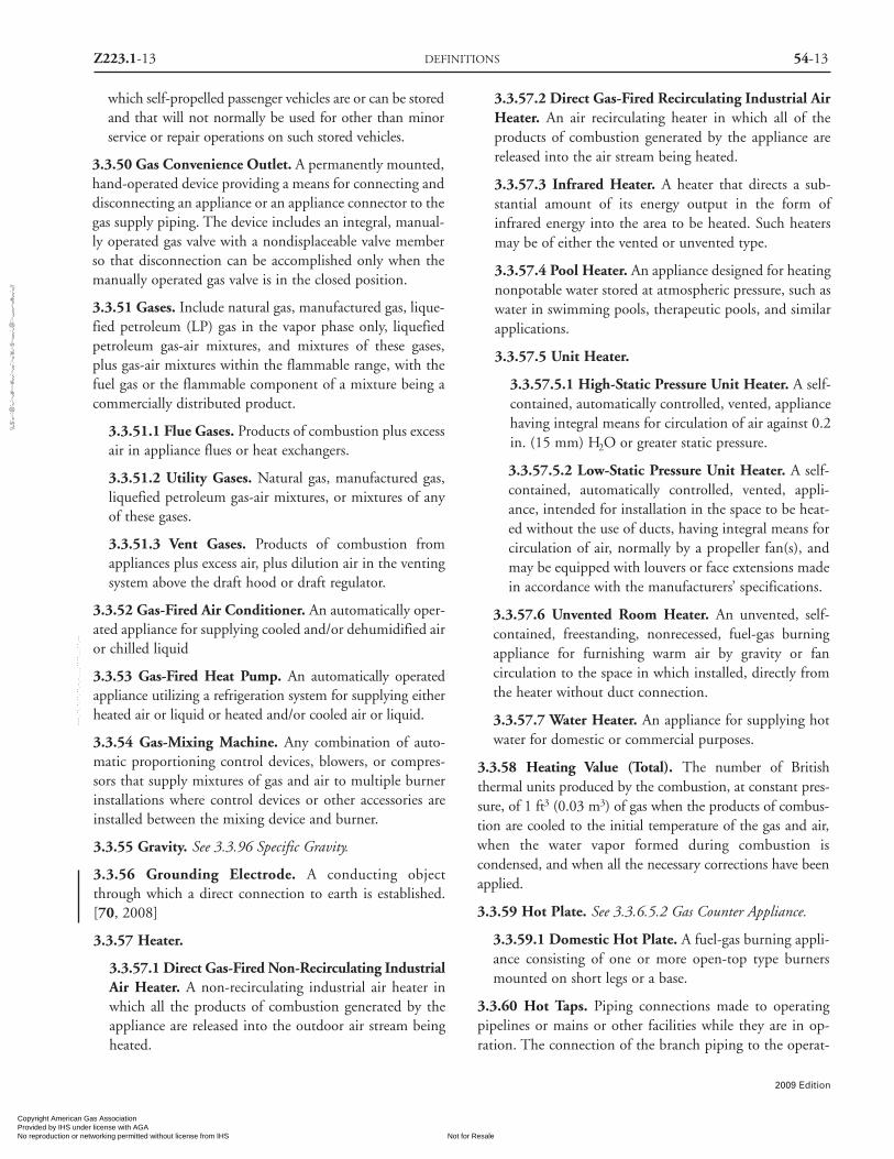
3.3.50 Gas Convenience Outlet. A permanently mounted,hand-operated device providing a means for connecting anddisconnecting an appliance or an appliance connector to thegas supply piping. The device includes an integral, manual-ly operated gas valve with a nondisplaceable valve memberso that disconnection can be accomplished only when themanually operated gas valve is in the closed position.
3.3.51 Gases. Include natural gas, manufactured gas, lique-fied petroleum (LP) gas in the vapor phase only, liquefiedpetroleum gas-air mixtures, and mixtures of these gases,plus gas-air mixtures within the flammable range, with thefuel gas or the flammable component of a mixture being acommercially distributed product.
3.3.51.1 Flue Gases. Products of combustion plus excessair in appliance flues or heat exchangers.
3.3.51.2 Utility Gases. Natural gas, manufactured gas,liquefied petroleum gas-air mixtures, or mixtures of anyof these gases.
3.3.51.3 Vent Gases. Products of combustion fromappliances plus excess air, plus dilution air in the ventingsystem above the draft hood or draft regulator.
3.3.52 Gas-Fired Air Conditioner. An automatically oper-ated appliance for supplying cooled and/or dehumidified airor chilled liquid
3.3.53 Gas-Fired Heat Pump. An automatically operatedappliance utilizing a refrigeration system for supplying eitherheated air or liquid or heated and/or cooled air or liquid.
3.3.54 Gas-Mixing Machine. Any combination of auto-matic proportioning control devices, blowers, or compres-sors that supply mixtures of gas and air to multiple burnerinstallations where control devices or other accessories areinstalled between the mixing device and burner.
3.3.55 Gravity. See 3.3.96 Specific Gravity.
3.3.56 Grounding Electrode. A conducting objectthrough which a direct connection to earth is established.[70, 2008]
3.3.57 Heater.
3.3.57.1 Direct Gas-Fired Non-Recirculating IndustrialAir Heater. A non-recirculating industrial air heater inwhich all the products of combustion generated by theappliance are released into the outdoor air stream beingheated.
3.3.57.2 Direct Gas-Fired Recirculating Industrial AirHeater. An air recirculating heater in which all of theproducts of combustion generated by the appliance arereleased into the air stream being heated.
3.3.57.3 Infrared Heater. A heater that directs a sub-stantial amount of its energy output in the form ofinfrared energy into the area to be heated. Such heatersmay be of either the vented or unvented type.
3.3.57.4 Pool Heater. An appliance designed for heatingnonpotable water stored at atmospheric pressure, such aswater in swimming pools, therapeutic pools, and similarapplications.
3.3.57.5 Unit Heater.
3.3.57.5.1 High-Static Pressure Unit Heater. A self-contained, automatically controlled, vented, appliancehaving integral means for circulation of air against 0.2in. (15 mm) H2O or greater static pressure.
3.3.57.5.2 Low-Static Pressure Unit Heater. A self-contained, automatically controlled, vented, appli-ance, intended for installation in the space to be heat-ed without the use of ducts, having integral means forcirculation of air, normally by a propeller fan(s), andmay be equipped with louvers or face extensions madein accordance with the manufacturers’ specifications.
3.3.57.6 Unvented Room Heater. An unvented, self-contained, freestanding, nonrecessed, fuel-gas burningappliance for furnishing warm air by gravity or fancirculation to the space in which installed, directly fromthe heater without duct connection.
3.3.57.7 Water Heater. An appliance for supplying hotwater for domestic or commercial purposes.
3.3.58 Heating Value (Total). The number of Britishthermal units produced by the combustion, at constant pres-sure, of 1 ft3 (0.03 m3) of gas when the products of combus-tion are cooled to the initial temperature of the gas and air,when the water vapor formed during combustion iscondensed, and when all the necessary corrections have beenapplied.
3.3.59 Hot Plate. See 3.3.6.5.2 Gas Counter Appliance.
3.3.59.1 Domestic Hot Plate. A fuel-gas burning appli-ance consisting of one or more open-top type burnersmounted on short legs or a base.
3.3.60 Hot Taps. Piping connections made to operatingpipelines or mains or other facilities while they are in op-ration. The connection of the branch piping to the operat-
Z223.1-13 DEFINITIONS 54-13
2009 Edition
Copyright American Gas Association Provided by IHS under license with AGA
Not for ResaleNo reproduction or networking permitted without license from IHS
--`,,```,,,,````-`-`,,`,,`,`,,`---
//^:^^#^~^^""~:@":^*^~$~"#:*~::*^~:^^#~~#^~:^:@
:~*:$"\\
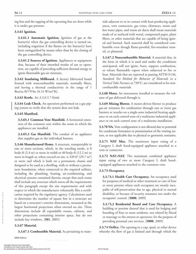
54-14 NATIONAL FUEL GAS CODE Z223.1-14
ing line and the tapping of the operating line are done whileit is under gas pressure.
3.3.61 Ignition.
3.3.61.1 Automatic Ignition. Ignition of gas at theburner(s) when the gas controlling device is turned on,including reignition if the flames on the burner(s) havebeen extinguished by means other than by the closing ofthe gas controlling device.
3.3.61.2 Sources of Ignition. Appliances or equipmentthat, because of their intended modes of use or opera-tion, are capable of providing sufficient thermal energy toignite flammable gas-air mixtures.
3.3.62 Insulating Millboard. A factory fabricated boardformed with noncombustible materials, normally fibers,and having a thermal conductivity in the range of 1Btu/in./ft2/°F/hr (0.14 W/m/°K).
3.3.63 Kettle. See 3.3.6.5.7 Kettle.
3.3.64 Leak Check. An operation performed on a gas pip-ing system to verify that the system does not leak.
3.3.65 Maniford.
3.3.65.1 Common Vent Manifold. A horizontal exten-sion of the common vent within the room in which theappliances are installed.
3.3.65.2 Gas Manifold. The conduit of an appliancethat supplies gas to the individual burners.
3.3.66 Manufactured Home. A structure, transportable inone or more sections, which, in the traveling mode, is 8body-ft (2.4 m) or more in width or 40 body-ft (12.2 m) ormore in length or, when erected on site, is 320 ft2 (29.7 m2)or more and which is built on a permanent chassis anddesigned to be used as a dwelling, with or without a perma-nent foundation, when connected to the required utilities,including the plumbing, heating, air-conditioning, andelectrical systems contained therein; except that such termsshall include any structure which meets all the requirementsof this paragraph except the size requirements and withrespect to which the manufacturer voluntarily files a certifi-cation required by the regulatory agency. Calculations usedto determine the number of square feet in a structure arebased on a structure's exterior dimensions, measured at thelargest horizontal projections when erected on site. Thesedimensions include all expandable rooms, cabinets, andother projections containing interior space, but do notinclude bay windows. [501, 2005]
3.3.67 Material.
3.3.67.1 Combustible Material. As pertaining to mate-
rials adjacent to or in contact with heat-producing appli-ances, vent connectors, gas vents, chimneys, steam andhot water pipes, and warm air ducts shall mean materialsmade of or surfaced with wood, compressed paper, plantfibers, or other materials that are capable of being ignit-ed and burned. Such material shall be considered com-bustible even though flame-proofed, fire-retardant treat-ed, or plastered.
3.3.67.2 Noncombustible Material. A material that, inthe form in which it is used and under the conditionsanticipated, will not ignite, burn, support combustion,or release flammable vapors when subjected to fire orheat. Materials that are reported as passing ASTM E136,Standard Test Method for Behavior of Materials in aVertical Tube Furnace at 750°C, are considered to be non-combustible materials.
3.3.68 Meter. An instrument installed to measure the vol-ume of gas delivered through it.
3.3.69 Mixing Blower. A motor-driven blower to producegas-air mixtures for combustion through one or more gasburners or nozzles on a single-zone industrial heating appli-ance or on each control zone of a multizone industrial appli-ance or on each control zone of a multizone installation.
3.3.70 NA. Vent configuration is not allowed due to potentialfor condensate formation or pressurization of the venting sys-tem, or not applicable due to physical or geometric restraints.
3.3.71 NAT Max. The maximum input rating of aCategory I, draft hood-equipped appliance attached to avent or connector.
3.3.72 NAT+NAT. The maximum combined applianceinput rating of two or more Category I, draft hood-equipped appliances attached to the common vent.
3.3.73 Occupancy.
3.3.73.1 Health Care Occupancy. An occupancy usedfor purposes of medical or other treatment or care of fouror more persons where such occupants are mostly inca-pable of self-preservation due to age, physical or mentaldisability, or because of security measures not under theoccupants’ control. [5000, 2009]
3.3.73.2 Residential Board and Care Occupancy. Abuilding or portion thereof that is used for lodging andboarding of four or more residents, not related by bloodor marriage to the owners or operators, for the purpose ofproviding personal care services. [5000, 2009]
3.3.74 Orifice. The opening in a cap, spud, or other devicewhereby the flow of gas is limited and through which the
2009 Edition
Copyright American Gas Association Provided by IHS under license with AGA
Not for ResaleNo reproduction or networking permitted without license from IHS
--`,,```,,,,````-`-`,,`,,`,`,,`---
//^:^^#^~^^""~:@":^*^~$~"#:*~::*^~:^^#~~#^~:^:@
:~*:$"\\

gas is discharged to the burner.
3.3.75 Oven, Gas Baking and Roasting. See 3.3.6.5.1,Baking and Roasting Gas Oven.
3.3.76 Parking Structure. A building, structure, or portionthereof used for the parking of motor vehicles.
3.3.76.1 Basement or Underground ParkingStructure. A parking structure or portion thereof locatedbelow finished ground level.
3.3.76.2 Enclosed Parking Structure. Having exteriorenclosing walls that have less than 25 percent of the totalwall area open to atmosphere at each level using at leasttwo sides of the structure.
3.3.77 Pilot. A small flame that is utilized to ignite the gasat the main burner or burners.
3.3.78 Pipe. Rigid conduit of iron, steel, copper, brass, alu-minum, or plastic.
3.3.78.1 Equivalent Length Pipe. The resistance ofvalves, controls, and fittings to gas flow expressed asequivalent length of straight pipe for convenience in cal-culating pipe sizes.
3.3.79 Piping. As used in this code, either pipe, tubing, orboth. See 3.3.78 Pipe, 3.3.104 Tubing.
3.3.79.1 Concealed Gas Piping. Gas piping, that, whenin place in a finished building, would require removal ofpermanent construction to gain access to the piping.
3.3.79.2 Control Piping. All piping, valves, and fittingsused to interconnect air, gas, or hydraulically operatedcontrol apparatus or instrument transmitters andreceivers.
3.3.80 Plenum. A compartment or chamber to which oneor more ducts are connected and that forms part of the airdistribution system.
3.3.81 Pressure. Unless otherwise stated, is expressed inpounds per square inch above atmospheric pressure.
3.3.81.1 Atmospheric Pressure. The pressure of theweight of air on the surface of the earth, approximately14.7 pounds/square inch (psia) (101 kPa absolute) at sealevel.
3.3.81.2 Back Pressure. Pressure against which a fluid isflowing, resulting from friction in lines, restrictions inpipes, valves, pressure in vessel to which fluid is flowing,hydrostatic head, or other impediment that causes resist-ance to fluid flow.
3.3.81.3 Design Pressure. The maximum operatingpressure permitted by this code, as determined by the
design procedures applicable to the materials involved.
3.3.81.4 Maximum Working Pressure. The maximumpressure at which a piping system may be operated inaccordance with the provisions of this code.
3.3.82 Pressure Drop. The loss in pressure due to friction orobstruction in pipes, valves, fittings, regulators, and burners.
3.3.83 Pressure Test. An operation performed to verify thegastight integrity of gas piping following its installation ormodification.
3.3.84 Purge. To free a gas conduit of air or gas, or a mix-ture of gas and air.
3.3.85 Qualified Agency. Any individual, firm, corporation,or company that either in person or through a representativeis engaged in and is responsible for (a) the installation, test-ing, or replacement of gas piping or (b) the connection,installation, testing, repair, or servicing of appliances andequipment; that is experienced in such work; that is familiarwith all precautions required; and that has complied with allthe requirements of the authority having jurisdiction.
3.3.86 Range. See 3.3.6.5.4 Gas Range.
3.3.87 Refrigerator (Using Gas Fuel). An appliance that isdesigned to extract heat from a suitable chamber.
3.3.88 Regulator.
3.3.88.1 Appliance Regulator. A pressure regulator forcontrolling pressure to the appliance manifold.
3.3.88.2 Draft Regulator. A device that functions tomaintain a desired draft in the appliance by automatical-ly reducing the draft to the desired value.
3.3.88.2.1 Barometric Draft Regulator. A balanceddamper device attached to a chimney, vent connector,breeching, or flue gas manifold to control chimney draft.
3.3.88.3 Line Gas Regulator. A pressure regulatorplaced in a gas line between the service regulator and theappliance regulator.
3.3.88.4 Monitoring Regulator. A pressure regulator setin series with another pressure regulator for the purposeof automatically taking over in an emergency the controlof the pressure downstream of the regulator in case thatpressure tends to exceed a set maximum.
3.3.88.5 Pressure Regulator. Equipment placed in a gasline for reducing, controlling, and maintaining the pres-sure in that portion of the piping system downstream ofthe equipment.
3.3.88.6 Series Regulator. A pressure regulator in serieswith one or more other pressure regulators.
Z223.1-15 DEFINITIONS 54-15
2009 Edition
Copyright American Gas Association Provided by IHS under license with AGA
Not for ResaleNo reproduction or networking permitted without license from IHS
--`,,```,,,,````-`-`,,`,,`,`,,`---
//^:^^#^~^^""~:@":^*^~$~"#:*~::*^~:^^#~~#^~:^:@:~*:$"\\

54-16 NATIONAL FUEL GAS CODE Z223.1-16
3.3.88.7 Service Regulator. A pressure regulatorinstalled by the serving gas supplier to reduce and limitthe service line gas pressure to delivery pressure.
3.3.89 Relief Opening. The opening provided in a drafthood to permit the ready escape to the atmosphere of theflue products from the draft hood in the event of no draft,backdraft, or stoppage beyond the draft hood and to permitinspiration of air into the draft hood in the event of a strongchimney updraft.
3.3.90 Room Large in Comparison with Size ofAppliance. Rooms having a volume equal to at least 12times the total volume of a furnace or air-conditioningappliance and at least 16 times the total volume of a boiler.
3.3.91 Safety Blowout (Backfire Preventer). A protectivedevice located in the discharge piping of large mixingmachines, incorporating a bursting disc for excessive pres-sure release, means for stopping a flame front, and an elec-tric switch or other release mechanism for actuating a built-in or separate safety shutoff.
3.3.92 Service Head Adapter. A transition fitting for usewith plastic piping (which is encased in non-pressure-carry-ing metal pipe) that connects the metal pipe casing and plas-tic pipe and tubing to the remainder of the piping system.
3.3.93 Service Meter Assembly. The piping and fittingsinstalled by the serving gas supplier to connect the inlet sideof the meter to the gas service and to connect the outlet sideof the meter to the customer’s house or yard piping.
3.3.94 Service Regulator. See 3.3.88.5, Pressure Regulator;and 3.3.88.7,Service Regulator.
3.3.95 Shutoff. See 3.3.105.1 Appliance Shutoff Valve and3.3.105.5 Service Shutoff Valve.
3.3.96 Specific Gravity. As applied to gas, the ratio of theweight of a given volume to that of the same volume of air,both measured under the same conditions.
3.3.97 Steam Cooker. See 3.3.6.5.5 Gas Steam Cooker.
3.3.98 Steam Generator. See 3.3.6.5.6 Gas Steam Generator.
3.3.99 Stress. The resultant internal force that resistschange in the size or shape of a body acted on by externalforces. In this code, stress is often used as being synonymouswith unit stress, which is the stress per unit area (psi).
3.3.99.1 Hoop Stress. The stress in a pipe wall, actingcircumferentially in a plane perpendicular to the longitu-dinal axis of the pipe and produced by the pressure of thefluid in the pipe.
3.3.100 System.
3.3.100.1 Central Premix System. A system that dis-tributes flammable gas-air mixtures to two or moreremote stations.
3.3.100.2 Fan-Assisted Combustion System. An appli-ance equipped with an integral mechanical means toeither draw or force products of combustion through thecombustion chamber or heat exchanger.
3.3.100.3 Hybrid Pressure System. A piping system inwhich the pressure at the point of delivery is reduced byone or more line pressure regulators prior to the appli-ance connection.
3.3.100.4 Mechanical Exhaust System. Equipmentinstalled in and made a part of the vent, to provide therequired flow of gases through the vent.
3.3.100.5 Piping System. All piping, valves, and fittingsfrom the outlet of the point of delivery from the suppli-er to the outlets of the equipment shutoff valves.
3.3.100.6* Venting System. A continuous open pas-sageway from the flue collar or draft hood of an applianceto the outdoors for the purpose of removing flue or ventgases.
3.3.100.6.1 Venting System, Mechanical Draft,Forced. A venting system in which a fan or othermechanical device is used to cause the flow of flue orvent gases under positive vent pressure.
3.3.100.6.2 Venting System, Mechanical Draft. Aventing system designed to remove flue or vent gases bymechanical means, which may consist of an induceddraft portion under nonpositive static pressure or aforced draft portion under positive static pressure.
3.3.100.6.3 Venting System, Natural Draft. A vent-ing system that relies on natural draft to convey theproducts of combustion.
3.3.101 Tensile Strength. The highest unit tensile stress(referred to the original cross section) a material can sustainbefore failure (psi).
3.3.102 Thermostat.
3.3.102.1 Electric Switch Type Thermostat. A devicethat senses changes in temperature and controls electri-cally, by means of separate components, the flow of gasto the burner(s) to maintain selected temperatures.
3.3.102.2 Integral Gas Valve Type Thermostat. An auto-matic device, actuated by temperature changes, designed tocontrol the gas supply to the burner(s) in order to maintain
2009 Edition
Copyright American Gas Association Provided by IHS under license with AGA
Not for ResaleNo reproduction or networking permitted without license from IHS
--`,,```,,,,````-`-`,,`,,`,`,,`---
//^:^
^#^~
^^""
~:@
":^*^
~$~"
#:*~
::*^~
:^^#
~~#^
~:^:
@:~
*:$"
\\

temperatures between predetermined limits, and in whichthe thermal actuating element is an integral part of thedevice: (1) graduating thermostat, a thermostat in whichthe motion of the valve is approximately in direct propor-tion to the effective motion of the thermal element inducedby temperature change; (2) snap-acting thermostat, a ther-mostat in which the thermostatic valve travels instantlyfrom the closed to the open position, and vice versa.
3.3.103 Thread Joint Compounds. Nonhardening mate-rials used on pipe threads to ensure a seal.
3.3.104 Tubing. Semirigid conduit of copper, steel, alu-minum, CSST or plastic.
3.3.105 Valve. A device used in piping to control the gas sup-ply to any section of a system of piping or to an appliance.
3.3.105.1 Appliance Shutoff Valve. A valve located inthe piping system, used to shut off individual equipment.
3.3.105.2 Automatic Valve. An automatic or semiauto-matic device consisting essentially of a valve and operatorthat control the gas supply to the burner(s) during oper-ation of an appliance.
3.3.105.3 Excess Flow Valve (EFV). A valve designed toactivate when the fuel gas passing through it exceeds aprescribed flow rate.
3.3.105.3 Manual Reset Valve. An automatic shutoffvalve installed in the gas supply piping and set to shut offwhen unsafe conditions occur. The device remains closeduntil manually reopened.
3.3.105.4 Relief Valve. A safety valve designed to fore-stall the development of a dangerous condition by reliev-ing either pressure, temperature, or vacuum in a hotwater supply system.
3.3.105.4.1 Pressure Relief Valve. A valve that auto-matically opens and closes a relief vent, depending onwhether the pressure is above or below a predeter-mined value.
3.3.105.4.2 Temperature Relief Valve. A valve thatautomatically opens and automatically closes a reliefvent, depending on whether the temperature is aboveor below a predetermined value.
3.3.105.4.3 Vacuum Relief Valve. A valve that automat-ically opens and closes a vent for relieving a vacuum with-in the hot water supply system, depending on whetherthe vacuum is above or below a predetermined value.
3.3.105.5 Service Shutoff Valve. A valve, installed bythe serving gas supplier between the service meter orsource of supply and the customer piping system, to shut
off the entire piping system.
3.3.106 Valve Member. That part of a gas valve rotatingwithin or in respect to the valve body that, by its positionwith respect to the valve body, controls the flow of gas.
3.3.106.1 Nondisplaceable Valve Member. A valve mem-ber that cannot be moved from its seat by a force appliedto the handle, or to any exterior portion of the valve.
3.3.107 Vent. A passageway used to convey flue gases fromappliances or their vent connectors to the outdoors.
3.3.107.1 Common Vent. That portion of a vent orchimney system that conveys products of combustionfrom more than one appliance.
3.3.107.2 Gas Vent. A passageway composed of listedfactory-built components assembled in accordance withthe manufacturer’s installation instructions for conveyingvent gases from appliances or their vent connectors to theoutdoors.
3.3.107.2.1 Gas Vent, Special Type. Gas vents forventing listed Category II, III, and IV appliances.
3.3.107.2.2 Gas Vent, Type B. A vent for venting list-ed gas appliances with draft hoods and other CategoryI appliances listed for use with Type B gas vents.
3.3.107.2.3 Gas Vent, Type B-W. A vent for ventinglisted wall furnaces.
3.3.107.2.4 Gas Vent, Type L. A vent for ventingappliances listed for use with Type L vents and appli-ances listed for use with Type B gas vents.
3.3.107.3 Regulator Vent. The opening in the atmos-pheric side of the regulator housing permitting the in andout movement of air to compensate for the movement ofthe regulator diaphragm.
3.3.108 Vent Connector. The pipe or duct that connects afuel-gas burning appliance to a vent or chimney.
3.3.109 Vent Offset. An arrangement of two or more fit-tings and pipe installed for the purpose of locating a verti-cal section of vent pipe in a different but parallel plane withrespect to an adjacent section of vertical vent pipe.
3.3.110 Venting. Removal of combustion products as wellas process fumes to the outer air.
3.3.111 Wall Head Adapter. A transition fitting for termi-nating plastic pipe inside of buildings at the building wall.
3.3.112 Zero Governor. A regulating device that is nor-mally adjusted to deliver gas at atmospheric pressure withinits flow rating.
Z223.1-17 DEFINITIONS 54-17
2009 Edition
Copyright American Gas Association Provided by IHS under license with AGA
Not for ResaleNo reproduction or networking permitted without license from IHS
--`,,```,,,,````-`-`,,`,,`,`,,`---
//^:^^#^~^^""~:@":^*^~$~"#:*~::*^~:^^#~~#^~:^:@
:~*:$"\\

54-18 NATIONAL FUEL GAS CODE Z223.1-18
Chapter 4 General
4.1 Qualified Agency.
Installation, testing, and replacement of gas piping, appli-ances, or accessories, and repair and servicing of equipment,shall be performed only by a qualified agency.
4.2 Interruption of Service.
4.2.1 Notification of Interrupted Service. When the gassupply is to be turned off, it shall be the duty of the quali-fied agency to notify all affected users. Where two or moreusers are served from the same supply system, precautionsshall be exercised to ensure that service only to the properuser is turned off.
Exception: In cases of emergency, affected users shall be notifiedas soon as possible of the actions taken by the qualified agency.
4.2.2 Work Interruptions. When interruptions in workoccur while repairs or alterations are being made to an exist-ing piping system, the system shall be left in a safe condition.
4.3 Prevention of Accidental Ignition.
4.3.1 Potential Ignition Sources. Where work is beingperformed on piping that contains or has contained gas, thefollowing shall apply:(1) Provisions for electrical continuity shall be made
before alterations are made in a metallic piping system.(2) Smoking, open flames, lanterns, welding, or other
sources of ignition shall not be permitted.(3) A metallic electrical bond shall be installed around the
location of cuts in metallic gas pipes made by otherthan cutting torches. Where cutting torches, welding,or other sources of ignition are unavoidable, it shall bedetermined that all sources of gas or gas-air mixtureshave been secured and that all flammable gas or liquidshave been cleared from the area. Piping shall be purgedas required in Section 8.3 before welding or cuttingwith a torch is attempted.
(4) Artificial illumination shall be restricted to listed safe-ty-type flashlights and safety lamps. Electric switchesshall not be operated, on or off.
4.3.2 Handling of Flammable Liquids.
4.3.2.1 Drip Liquids. Liquid that is removed from adrip in existing gas piping shall be handled to avoidspillage or ignition. The gas supplier shall be notifiedwhen drip liquids are removed.
4.3.2.2 Other Flammable Liquids. Flammable liquidsused by the installer shall be handled with precaution andshall not be left within the premises from the end of oneworking day to the beginning of the next.
Chapter 5 Gas Piping System Design,Materials, and Components
5.1 Piping Plan.
5.1.1 Installation of Piping System. Where required bythe authority having jurisdiction, a piping sketch or planshall be prepared before proceeding with the installation.This plan shall show the proposed location of piping, thesize of different branches, the various load demands, andthe location of the point of delivery.
5.1.2 Addition to Existing System.
5.1.2.1 When additional appliances are being connectedto a gas piping system, the existing piping shall be checkedto determine if it has adequate capacity [see 5.4.3].
5.1.2.2 If inadequate, the existing system shall beenlarged as required, or separate gas piping of adequatecapacity shall be provided.
5.2 Provision for Locationof Point of Delivery.
The location of the point of delivery shall be acceptable tothe serving gas supplier.
5.3 Interconnections betweenGas Piping Systems.
5.3.1 Interconnections Supplying Separate Users. Wheretwo or more meters, or two or more service regulators wheremeters are not provided, are located on the same premisesand supply separate users, the gas piping systems shall notbe interconnected on the outlet side of the meters or serviceregulators.
5.3.2 Interconnections for Stand-By Fuels.
5.3.2.1 Where a supplementary gas for stand by use isconnected downstream from a meter or a service regula-tor where a meter is not provided, equipment to preventbackflow shall be installed.
5.3.2.2 A three-way valve installed to admit the standby
2009 Edition
Copyright American Gas Association Provided by IHS under license with AGA
Not for ResaleNo reproduction or networking permitted without license from IHS
--`,,```,,,,````-`-`,,`,,`,`,,`---
//^:^
^#^~
^^""
~:@
":^*^
~$~"
#:*~
::*^~
:^^#
~~#^
~:^:
@:~
*:$"
\\

supply and at the same time shut off the regular supplyshall be permitted to be used for this purpose.
5.4 Sizing of Gas Piping Systems.
5.4.1* General Considerations. Gas piping systems shall beof such size and so installed as to provide a supply of gas suf-ficient to meet the maximum demand and supply gas to eachappliance inlet at not less than the minimum supply pressurerequired by the appliance.
5.4.2* Maximum Gas Demand.
5.4.2.1 The volume of gas to be provided (in cubic feetper hour) shall be determined directly from the manu-facturers’ input ratings of the appliances served. Wherethe input rating is not indicated, the gas supplier, appli-ance manufacturer, or a qualified agency shall be con-tacted, or the rating from Table 5.4.2.1 shall be used forestimating the volume of gas to be supplied.
5.4.2.2 The total connected hourly load shall be used asthe basis for piping sizing, assuming all appliances areoperating at full capacity simultaneously.
Exception. Sizing shall be permitted to be based upon estab-lished load diversity factors.
5.4.3* Sizing Methods. Gas piping shall be sized in accor-dance with one of the following:
(1) Pipe sizing tables or sizing equations in Chapter 6
(2) Other approved engineering methods acceptable to theauthority having jurisdiction
(3) Sizing tables included in a listed piping system manu-facturer’s installation instructions
5.4.4 Allowable Pressure Drop. The design pressure lossin any piping system under maximum probable flow condi-tions, from the point of delivery to the inlet connection ofthe appliance, shall be such that the supply pressure at theappliance is greater than or equal to the minimum pressurerequired by the appliance.
5.5 Piping System OperatingPressure Limitations.
5.5.1 Maximum Design Operating Pressure. The maxi-mum design operating pressure for piping systems locatedinside buildings shall not exceed 5 psi (34 kPa) unless oneor more of the following conditions are met:
(1)* The piping system is welded
Table 5.4.2.1 Approximate Gas Inputfor Typical Appliances
InputBtu/hr
Appliance (Approx.)
Space Heating UnitsWarm air furnace
Single family 100,000Multifamily, per unit 60,000
Hydronic boilerSingle family 100,000Multifamily, per unit 60,000
Space and Water Heating UnitsHydronic boiler
Single family 120,000Multifamily, per unit 75,000
Water Heating AppliancesWater heater, automatic storage 30 to 40 gal tank 35,000Water heater, automatic storage 50 gal tank 50,000Water heater, automatic instantaneous
Capacity at 2 gal/min 142,800Capacity at 4 gal/min 285,000Capacity at 6 gal/min 428,400
Water heater, domestic, circulating or side-arm 35,000
Cooking AppliancesRange, free standing, domestic 65,000Built-in oven or broiler unit, domestic 25,000Built-in top unit, domestic 40,000
Other AppliancesRefrigerator 3,000Clothes dryer, Type 1 (domestic) 35,000Gas fireplace direct vent 40,000Gas log 80,000Barbecue 40,000Gas light 2,500
For SI units: 1 Btu/hr = 0.293 W.
(2) The piping is located in a ventilated chase or other-wise enclosed for protection against accidental gasaccumulation
(3) The piping is located inside buildings or separate areasof buildings used exclusively for one of the following:(a) Industrial processing or heating(b) Research(c) Warehousing(d) Boiler or mechanical rooms
(4) The piping is a temporary installation for buildingsunder construction
Z223.1-19 GAS PIPING SYSTEM DESIGN, MATERIALS, AND COMPONENTS 54-19
2009 Edition
Copyright American Gas Association Provided by IHS under license with AGA
Not for ResaleNo reproduction or networking permitted without license from IHS
--`,,```,,,,````-`-`,,`,,`,`,,`---
//^:^
^#^~
^^""
~:@
":^*^
~$~"
#:*~
::*^~
:^^#
~~#^
~:^:
@:~
*:$"
\\

54-20 NATIONAL FUEL GAS CODE Z223.1-20
(5) The piping serves appliances or equipment used foragricultural purposes.
(6) The piping system is an LP-Gas piping system with adesign operating pressure greater than 20 psi (140 kPa)and complies with NFPA 58, Liquefied Petroleum GasCode.
5.5.2 Liquefied Petroleum Gas Systems. LP-Gas systemsdesigned to operate below -5°F (-21°C) or with butane or apropane-butane mix shall be designed to either accommodateliquid LP-Gas or prevent LP-Gas vapor from condensingback into a liquid.
5.6* Acceptable Piping Materials andJoining Methods.
5.6.1 General.
5.6.1.1 Acceptable Materials. Materials used for pipingsystems shall comply with the requirements of this chapteror shall be acceptable to the authority having jurisdiction.
5.6.1.2 Used Materials. Pipe, fittings, valves, or othermaterials shall not be used again unless they are free offoreign materials and have been ascertained to be ade-quate for the service intended.
5.6.1.3 Other Materials. Material not covered by thestandards specifications listed herein shall be investigatedand tested to determine that it is safe and suitable for theproposed service and, in addition, shall be recommendedfor that service by the manufacturer and shall be accept-able to the authority having jurisdiction.
5.6.2 Metallic Pipe.
5.6.2.1 Cast-Iron. Cast-iron pipe shall not be used.
5.6.2.2 Steel and Wrought-Iron. Steel and wrought-ironpipe shall be at least of standard weight (Schedule 40) andshall comply with one of the following standards:(1) ANSI/ASME B36.10M, Welded and Seamless
Wrought Steel Pipe(2) ASTM A53, Standard Specification for Pipe, Steel,
Black and Hot-Dipped, Zinc-Coated Welded andSeamless
(3) ASTM A106, Standard Specification for SeamlessCarbon Steel Pipe for High-Temperature Service
5.6.2.3* Copper and Brass. Copper and brass pipe shallnot be used if the gas contains more than an average of0.3 grains of hydrogen sulfide per 100 scf of gas (0.7mg/100 L).
5.6.2.4 Threaded Copper, Brass and Aluminum.
Threaded copper, brass, or aluminum-alloy pipe shall notbe used with gases corrosive to such material.
5.6.2.5 Aluminum-Alloy. Aluminum-alloy pipe shallcomply with ASTM B241, Standard Specification forAluminum and Aluminum-Alloy Seamless Pipe andSeamless Extruded Tube (except that the use of alloy 5456is prohibited) and shall be marked at each end of eachlength indicating compliance. Aluminum-alloy pipe shallbe coated to protect against external corrosion where it isin contact with masonry, plaster, or insulation or is sub-ject to repeated wettings by such liquids as water, deter-gents, or sewage. Aluminum-alloy pipe shall not be usedin exterior locations or underground.
5.6.3 Metallic Tubing. Seamless copper, aluminum-alloy,or steel tubing shall not be used with gases corrosive to suchmaterial.
5.6.3.1 Steel. Steel tubing shall comply with ASTM A254,Standard Specification for Copper-Brazed Steel Tubing.
5.6.3.2* Copper and Brass. Copper and brass tubingshall not be used if the gas contains more than an averageof 0.3 grains of hydrogen sulfide per 100 scf of gas (0.7mg/100 L). Copper tubing shall comply with standardType K or L of ASTM B88, Standard Specification forSeamless Copper Water Tube, or ASTM B280, StandardSpecification for Seamless Copper Tube for AirConditioning and Refrigeration Field Service.
5.6.3.3 Aluminum. Aluminum-alloy tubing shall com-ply with ASTM B210, Standard Specification forAluminum and Aluminum-Alloy Drawn Seamless Tubes, orASTM B241, Standard Specification for Aluminum andAluminum-Alloy Seamless Pipe and Seamless ExtrudedTube. Aluminum-alloy tubing shall be coated to protectagainst external corrosion where it is in contact withmasonry, plaster, or insulation or is subject to repeatedwettings by such liquids as water, detergent, or sewage.Aluminum-alloy tubing shall not be used in exterior loca-tions or underground.
5.6.3.4 Corrugated Stainless Steel. Corrugated stainlesssteel tubing shall be listed in accordance with ANSI LC1/CSA 6.26, Fuel Gas Piping Systems Using CorrugatedStainless Steel Tubing (CSST).
5.6.4 Plastic Pipe, Tubing, and Fittings.
5.6.4.1 Standard and Marking. Plastic pipe, tubing,and fittings used to supply fuel gas shall conform toASTM D2513, Standard Specification for ThermoplasticGas Pressure Pipe, Tubing, and Fittings. Pipe to be usedshall be marked “gas” and “ASTM D2513.”
2009 Edition
Copyright American Gas Association Provided by IHS under license with AGA
Not for ResaleNo reproduction or networking permitted without license from IHS
--`,,```,,,,````-`-`,,`,,`,`,,`---
//^:^
^#^~
^^""
~:@
":^*^
~$~"
#:*~
::*^~
:^^#
~~#^
~:^:
@:~
*:$"
\\

5.6.4.2* Regulator Vent Piping. Plastic pipe, tubing,and fittings used to connect regulator vents to remotevent terminations shall be PVC conforming to ANSI/UL651, Schedule 40 and 80 rigid PVC conduit and Fittings.PVC vent piping shall not be installed indoors.
5.6.4.3 Anodeless Risers. Anodeless risers shall complywith the following:(1) Factory-assembled anodeless risers shall be recom-
mended by the manufacturer for the gas used andshall be leak tested by the manufacturer in accor-dance with written procedures.
(2) Service head adapters and field-assembled anodelessrisers incorporating service head adapters shall berecommneded by the manufacturer for the gas usedand shall be design-certified to meet the require-ments of Category I of ASTM D2513, StandardSpecification for Thermoplastic Gas Pressure Pipe,Tubing, and Fittings, and 49 CFR 192.281(e). Themanufacturer shall provide the user qualified instal-lation instructions as prescribed by 49 CFR192.283(b).
(3) The use of plastic pipe, tubing, and fittings in undi-luted liquefied petroleum gas piping systems shallbe in accordance with NFPA 58, LiquefiedPetroleum Gas Code.
5.6.5 Workmanship and Defects. Gas pipe, tubing, andfittings shall be clear and free from cutting burrs and defectsin structure or threading and shall be thoroughly brushedand chip and scale blown. Defects in pipe, tubing, and fit-tings shall not be repaired. Defective pipe, tubing, and fit-tings shall be replaced. [See 8.1.1.3.]
5.6.6 Protective Coating. Where in contact with material oratmosphere exerting a corrosive action, metallic piping andfittings coated with a corrosion-resistant material shall beused. External or internal coatings or linings used on pipingor components shall not be considered as adding strength.
5.6.7 Metallic Pipe Threads.
5.6.7.1 Specifications for Pipe Threads. Metallic pipeand fitting threads shall be taper pipe threads and shallcomply with ANSI/ASME B1.20.1, Pipe Threads,General Purpose, Inch.
5.6.7.2 Damaged Threads. Pipe with threads that arestripped, chipped, corroded, or otherwise damaged shall notbe used. Where a weld opens during the operation of cut-ting or threading, that portion of the pipe shall not be used.
5.6.7.3 Number of Threads. Field threading of metallicpipe shall be in accordance with Table 5.6.7.3.
Table 5.6.7.3 Specifications forThreading Metallic Pipe
Approximate Length Approximate No.Iron Pipe of Threaded Portion of Threads To BeSize (in.) (in.) Cut
1⁄2 3⁄4 103⁄4 3⁄4 101 7⁄8 10
1 1⁄4 1 111 1⁄2 1 112 1 11
2 1⁄2 1 1⁄2 123 1 1⁄2 124 1 5⁄8 13
For SI units: 1 in. = 25.4 mm.
5.6.7.4 Thread Compounds. Thread (joint) com-pounds (pipe dope) shall be resistant to the action of liq-uefied petroleum gas or to any other chemical con-stituents of the gases to be conducted through the piping.
5.6.8 Metallic Piping Joints and Fittings. The type ofpiping joint used shall be suitable for the pressure-tempera-ture conditions and shall be selected giving consideration tojoint tightness and mechanical strength under the serviceconditions. The joint shall be able to sustain the maximumend force due to the internal pressure and any additionalforces due to temperature expansion or contraction, vibra-tion, fatigue, or the weight of the pipe and its contents.
5.6.8.1* Pipe Joints. Pipe joints shall be threaded,flanged, brazed or welded. Where nonferrous pipe isbrazed, the brazing materials shall have a melting point inexcess of 1,000°F (538°C). Brazing alloys shall not con-tain more than 0.05 percent phosphorus.
5.6.8.2 Tubing Joints. Tubing joints shall be made withapproved gas tubing fittings, brazed with a material hav-ing a melting point in excess of 1,000°F (538°C), or madeby with press connect fittings complying with ANSI LC4, Press-Connect Copper and Copper Alloy Fittings for Usein Fuel Gas Distribution Systems. Brazing alloys shall notcontain more than 0.05 percent phosphorus.
5.6.8.3 Flared Joints. Flared joints shall be used only insystems constructed from nonferrous pipe and tubingwhere experience or tests have demonstrated that thejoint is suitable for the conditions and where provisionsare made in the design to prevent separation of thejoints.
Z223.1-21 GAS PIPING SYSTEM DESIGN, MATERIALS, AND COMPONENTS 54-21
2009 Edition
Copyright American Gas Association Provided by IHS under license with AGA
Not for ResaleNo reproduction or networking permitted without license from IHS
--`,,```,,,,````-`-`,,`,,`,`,,`---
//^:^^#^~^^""~:@":^*^~$~"#:*~::*^~:^^#~~#^~:^:@
:~*:$"\\

54-22 NATIONAL FUEL GAS CODE Z223.1-22
5.6.8.4 Metallic Fittings (Including Valves, Strainers,Filters). Metallic fittings shall comply with the following:(1) Threaded fittings in sizes larger than 4 in. (100
mm) shall not be used unless acceptable to theauthority having jurisdiction.
(2) Fittings used with steel or wrought-iron pipe shallbe steel, brass, bronze, malleable iron, or cast iron.
(3) Fittings used with copper or brass pipe shall be cop-per, brass, or bronze.
(4) Fittings used with aluminum-alloy pipe shall be ofaluminum-alloy.
(5) Cast-Iron Fittings. Cast-iron fittings shall complywith the following:(a) Flanges shall be permitted.(b) Bushings shall not be used.(c) Fittings shall not be used in systems containing
flammable gas-air mixtures.(d) Fittings in sizes 4 in. (100 mm) and larger shall
not be used indoors unless approved by theauthority having jurisdiction.
(e) Fittings in sizes 6 in. (150 mm) and larger shallnot be used unless approved by the authority hav-ing jurisdiction.
(6) Aluminum-Alloy Fittings. Threads shall not form thejoint seal.
(7) Zinc-Aluminum-Alloy Fittings. Fittings shall not beused in systems containing flammable gas-airmixtures.
(8) Special Fittings. Fittings such as couplings, propri-etary-type joints, saddle tees, gland-type compres-sion fittings, and flared, flareless, or compression-type tubing fittings shall be (1) used within the fit-ting manufacturers’ pressure-temperature recom-mendations; (2) used within the service conditionsanticipated with respect to vibration, fatigue, ther-mal expansion, or contraction; (3) installed orbraced to prevent separation of the joint by gaspressure or external physical damage; and (4)acceptable to the authority having jurisdiction.
5.6.9 Plastic Piping, Joints, and Fittings. Plastic pipe,tubing, and fittings shall be joined in accordance with themanufacturers’ instructions. The following shall beobserved when making such joints:(1) The joint shall be designed and installed so that the
longitudinal pullout resistance of the joint will be atleast equal to the tensile strength of the plastic pipingmaterial.
(2) Heat-fusion joints shall be made in accordance withqualified procedures that have been established and
proven by test to produce gastight joints at least asstrong as the pipe or tubing being joined. Joints shallbe made with the joining method recommended bythe pipe manufacturer. Heat fusion fittings shall bemarked “ASTM D2513.”
(3) Where compression-type mechanical joints are used,the gasket material in the fitting shall be compatiblewith the plastic piping and with the gas distributed bythe system. An internal tubular rigid stiffener shall beused in conjunction with the fitting. The stiffener shallbe flush with the end of the pipe or tubing and shallextend at least to the outside end of the compressionfitting when installed. The stiffener shall be free ofrough or sharp edges and shall not be a force fit in theplastic. Split tubular stiffeners shall not be used.
(4) Plastic piping joints and fittings for use in liquefiedpetroleum gas piping systems shall be in accordancewith NFPA 58, Liquefied Petroleum Gas Code.
5.6.10 Flanges. All flanges shall comply with ANSI/ASMEB16.1, Gray Iron Pipe Flanges and Flanged Fittings: Classes25, 125, and 250, ANSI/ASME B16.20, Metallic GasketsFor Pipe Flanges: Ring-Joint, Spiral-Wound And Jacketed; orMSS SP-6, Standard Finishes for Contact Faces of PipeFlanges and Connecting-End Flanges of Valves and Fittings.The pressure-temperature ratings shall equal or exceed thatrequired by the application.
5.6.10.1 Flange Facings. Standard facings shall be per-mitted for use under this code. Where 150 psi (1034 kPa)steel flanges are bolted to Class 125 cast-iron flanges, theraised face on the steel flange shall be removed.
5.6.10.2 Lapped Flanges. Lapped flanges shall be usedonly aboveground or in exposed locations accessible forinspection.
5.6.11 Flange Gaskets. The material for gaskets shall becapable of withstanding the design temperature and pres-sure of the piping system and the chemical constituents ofthe gas being conducted without change to its chemical andphysical properties. The effects of fire exposure to the jointshall be considered in choosing the material.
5.6.11.1 Acceptable materials shall include the following:(1) Metal or metal-jacketed asbestos (plain or corrugated)(2) Asbestos(3) Aluminum “O” rings and spiral-wound metal gaskets
5.6.11.2 When a flanged joint is opened, the gasket shallbe replaced.
5.6.11.3 Full-face gaskets shall be used with all bronzeand cast-iron flanges.
2009 Edition
Copyright American Gas Association Provided by IHS under license with AGA
Not for ResaleNo reproduction or networking permitted without license from IHS
--`,,```,,,,````-`-`,,`,,`,`,,`---
//^:^^#^~^^""~:@":^*^~$~"#:*~::*^~:^^#~~#^~:^:@
:~*:$"\\

5.7* Gas Meters.
5.7.1 Capacity. Gas meters shall be selected for the maxi-mum expected pressure and permissible pressure drop.
5.7.2 Location.
5.7.2.1 Gas meters shall be located in ventilated spacesreadily accessible for examination, reading, replacement,or necessary maintenance.
5.7.2.2 Gas meters shall not be placed where they will besubjected to damage, such as adjacent to a driveway, undera fire escape, in public passages, halls, coal bins, or wherethey will be subject to excessive corrosion or vibration.
5.7.2.3 Gas meters shall not be located where they willbe subjected to extreme temperatures or sudden extremechanges in temperature. Meters shall not be located inareas where they are subjected to temperatures beyondthose recommended by the manufacturer.
5.7.3 Supports. Gas meters shall be supported or connectedto rigid piping so as not to exert a strain on the meters. Whereflexible connectors are used to connect a gas meter to down-stream piping at mobile homes in mobile home parks, themeter shall be supported by a post or bracket placed in a firmfooting or by other means providing equivalent support.
5.7.4 Meter Protection. Meters shall be protected againstoverpressure, back pressure, and vacuum, where such con-ditions are anticipated.
5.7.5 Identification. Gas piping at multiple meter installa-tions shall be marked by a metal tag or other permanentmeans designating the building or the part of the buildingbeing supplied and attached by the installing agency.
5.8* Gas Pressure Regulators.
5.8.1 Where Required. A line gas pressure regulator or gasappliance pressure regulator, as applicable, shall be installedwhere the gas supply pressure is higher than that at whichthe branch supply line or appliances are designed to operateor vary beyond design pressure limits.
5.8.2 Listing. Line gas pressure regulators shall be listed inaccordance with ANSI Z21.80/CSA 6.22, Line PressureRegulators.
5.8.3 Location. The gas pressure regulator shall be accessi-ble for servicing.
5.8.4 Regulator Protection. Pressure regulators shall beprotected against physical damage.
5.8.5 Venting.
5.8.5.1 Line Gas Pressure Regulators. Line gas pressureregulators shall comply with the following:(1) An independent vent to the exterior of the building,
sized in accordance with the regulator manufacturer’sinstructions, shall be provided where the location ofa regulator is such that a ruptured diaphragm willcause a hazard.(a) Where there is more than one regulator at a loca-
tion, each regulator shall have a separate vent to theoutdoors, or if approved by the authority havingjurisdiction, the vent lines shall be permitted to bemanifolded in accordance with accepted engineer-ing practices to minimize back pressure in the eventof diaphragm failure. [See 5.9.7 for information onproperly locating the vent.]
(b) Materials for vent piping shall be in accordancewith Section 5.6.
Exception: A regulator and vent limiting means combina-tion listed as complying with ANSI Z21.80/CSA 6.22,Line Pressure Regulators, shall be permitted to be usedwithout a vent to the outdoors.
(2) The vent shall be designed to prevent the entry ofwater, insects, or other foreign materials that couldcause blockage.
(3) The regulator vent shall terminate at least 3 ft (0.9m) from a source of ignition.
(4) At locations where regulators might be submergedduring floods, a special antiflood-type breather ventfitting shall be installed, or the vent line shall beextended above the height of the expected floodwaters.
(5) A regulator shall not be vented to the appliance flueor exhaust system.
5.8.5.2 Appliance Pressure Regulators. For venting ofgas appliance pressure regulators, see 9.1.19.
5.8.6 Bypass Piping. Valved and regulated bypasses shallbe permitted to be placed around gas line pressure regula-tors where continuity of service is imperative.
5.8.7 Identification. Line pressure regulators at multipleregulator installations shall be marked by a metal tag orother permanent means designating the building or the partof the building being supplied.
5.9 Overpressure Protection Devices.
5.9.1 General. Overpressure protection devices shall beprovided to prevent the pressure in the piping system fromexceeding that value that would cause unsafe operation ofany connected and properly adjusted appliance. [See 5.9.5.]
Z223.1-23 GAS PIPING SYSTEM DESIGN, MATERIALS, AND COMPONENTS 54-23
2009 Edition
Copyright American Gas Association Provided by IHS under license with AGA
Not for ResaleNo reproduction or networking permitted without license from IHS
--`,,```,,,,````-`-`,,`,,`,`,,`---
//^:^
^#^~
^^""
~:@
":^*^
~$~"
#:*~
::*^~
:^^#
~~#^
~:^:
@:~
*:$"
\\

54-24 NATIONAL FUEL GAS CODE Z223.1-24
5.9.1.1 The requirements of this section shall be met anda piping system deemed to have overpressure protectionwhere a service or line pressure regulator plus one otherdevice are installed such that the following occur:(1) Each device limits the pressure to a value that does
not exceed the maximum working pressure of thedownstream system.
(2) The individual failure of either device does notresult in overpressure of the downstream system.
5.9.1.2 The pressure regulating, limiting, and relievingdevices shall be properly maintained, inspection proce-dures shall be devised or suitable instrumentationinstalled to detect failures or malfunctions of such devices,and replacements or repairs shall be promptly made.
5.9.1.3 A pressure relieving or limiting device shall notbe required where (1) the gas does not contain materialsthat could seriously interfere with the operation of theservice or line pressure regulator; (2) the operating pres-sure of the gas source is 60 psi (414 kPa) or less; and (3)the service or line pressure regulator has all of the follow-ing design features or characteristics:(1) Pipe connections to the service or line regulator do
not exceed 2 in. nominal diameter.(2) The regulator is self-contained with no external stat-
ic or control piping.(3) The regulator has a single port valve with an orifice
diameter no greater than that recommended by themanufacturer for the maximum gas pressure at theregulator inlet.
(4) The valve seat is made of resilient material designedto withstand abrasion of the gas, impurities in thegas, and cutting by the valve and to resist permanentdeformation where it is pressed against the valve port.
(5) The regulator is capable, under normal operatingconditions, of regulating the downstream pressurewithin the necessary limits of accuracy and of limit-ing the discharge pressure under no-flow conditionsto not more than 150 percent of the discharge pres-sure maintained under flow conditions.
5.9.2 Devices.
5.9.2.1 Pressure relieving or pressure limiting devicesshall be one of the following:(1) Spring-loaded relief device(2) Pilot-loaded back pressure regulator used as a relief
valve so designed that failure of the pilot system orexternal control piping will cause the regulator reliefvalve to open
(3) A monitoring regulator installed in series with theservice or line pressure regulator
(4) A series regulator installed upstream from the serv-ice or line regulator and set to continuously limitthe pressure on the inlet of the service or line regu-lator to the maximum working pressure of thedownstream piping system
(5) An automatic shutoff device installed in series withthe service or line pressure regulator and set to shutoff when the pressure on the downstream piping sys-tem reaches the maximum working pressure or someother predetermined pressure less than the maximumworking pressure. This device shall be designed sothat it will remain closed until manually reset.
(6) A liquid seal relief device that can be set to openaccurately and consistently at the desired pressure.
5.9.2.2 The devices in 5.9.2.1 shall be installed either asan integral part of the service or line pressure regulator oras separate units. Where separate pressure relieving orpressure limiting devices are installed, they shall complywith 5.9.3 through 5.9.8.
5.9.3 Construction and Installation. All pressure relievingor pressure limiting devices shall meet the followingrequirements:(1) Be constructed of materials so that the operation of the
device will not be impaired by corrosion of externalparts by the atmosphere or of internal parts by the gas.
(2) Be designed and installed so they can be operated todetermine whether the valve is free. The devices shallalso be designed and installed so they can be tested todetermine the pressure at which they will operate andexamined for leakage when in the closed position.
5.9.4 External Control Piping. External control pipingshall be protected from falling objects, excavations, or othercauses of damage and shall be designed and installed so thatdamage to any control piping shall not render both the reg-ulator and the overpressure protective device inoperative.
5.9.5 Setting. Each pressure limiting or pressure relievingdevice shall be set so that the pressure shall not exceed a safelevel beyond the maximum allowable working pressure forthe piping and appliances connected.
5.9.6 Unauthorized Operation. Precautions shall be takento prevent unauthorized operation of any shutoff valve thatwill make a pressure relieving valve or pressure limitingdevice inoperative. The following are acceptable methodsfor complying with this provision:(1) Lock the valve in the open position. Instruct author-
2009 Edition
Copyright American Gas Association Provided by IHS under license with AGA
Not for ResaleNo reproduction or networking permitted without license from IHS
--`,,```,,,,````-`-`,,`,,`,`,,`---
//^:^^#^~^^""~:@":^*^~$~"#:*~::*^~:^^#~~#^~:^:@
:~*:$"\\

ized personnel in the importance of leaving the shutoffvalve open and of being present while the shutoff valveis closed so that it can be locked in the open positionbefore leaving the premises.
(2) Install duplicate relief valves, each having adequatecapacity to protect the system, and arrange the isolatingvalves or three-way valve so that only one safety devicecan be rendered inoperative at a time.
5.9.7 Vents. The discharge stacks, vents, or outlet parts ofall pressure relieving and pressure limiting devices shall belocated so that gas is safely discharged to the outdoors.
5.9.7.1 Discharge stacks or vents shall be designed toprevent the entry of water, insects, or other foreignmaterial that could cause blockage.
5.9.7.2 The discharge stack or vent line shall be at leastthe same size as the outlet of the pressure relieving device.
5.9.8 Size of Fittings, Pipe, and Openings. The fittings,pipe and openings located between the system to be pro-tected and the pressure relieving device shall be sized to pre-vent hammering of the valve and to prevent impairment ofrelief capacity.
5.10 Back Pressure Protection.
5.10.1 Where to Install.
5.10.1.1 Protective devices shall be installed as close tothe equipment as practical where the design of equip-ment connected is such that air, oxygen, or standby gasescould be forced into the gas supply system.
5.10.1.2 Gas and air combustion mixers incorporatingdouble diaphragm “zero” or “atmosphere” governors orregulators shall require no further protection unless con-nected directly to compressed air or oxygen at pressuresof 5 psi (34 kPa) or more.
5.10.2 Protective Devices. Protective devices shall includebut are not limited to the following:(1) Check valves(2) Three-way valves (of the type that completely closes
one side before starting to open the other side)(3) Reverse flow indicators controlling positive shutoff valves(4) Normally closed air-actuated positive shutoff pressure
regulators
5.11 Low-Pressure Protection.
A protective device shall be installed between the meter and
the appliance if the operation of the appliance is such (i.e., gascompressors) that it could produce a vacuum or a dangerousreduction in gas pressure at the meter. Such devices include,but are not limited to, mechanical, diaphragm-operated, orelectrically operated low-pressure shutoff valves.
5.12 Shutoff Valves.
Shutoff valves shall be approved and shall be selected givingconsideration to pressure drop, service involved, emergencyuse, and reliability of operation. Shutoff valves of size 1 in.National Pipe Thread and smaller shall be listed.
5.13 Excess Flow Valve(s).
Where automatic excess flow valves are installed, they shallbe listed for the application and shall be sized and installedin accordance with the manufacturers' instructions.
5.14 Expansion and Flexibility.
5.14.1 Design. Piping systems shall be designed to havesufficient flexibility to prevent thermal expansion or con-traction from causing excessive stresses in the piping mate-rial, excessive bending or loads at joints, or undesirableforces or moments at points of connections to appliancesand equipment and at anchorage or guide points. Formalcalculations or model tests shall be required only wherereasonable doubt exists as to the adequate flexibility of thesystem.
5.14.1.1 Flexibility shall be provided by the use of bends,loops, offsets, or couplings of the slip type. Provisionshall be made to absorb thermal changes by the use ofexpansion joints of the bellows type, or by the use of“ball” or “swivel” joints. Expansion joints of the slip typeshall not be used inside buildings or for thermal expan-sion. Where expansion joints are used, anchors or tiesof sufficient strength and rigidity shall be installed toprovide for end forces due to fluid pressure and othercauses.
5.14.1.2 Pipe alignment guides shall be used with expan-sion joints according to the recommended practice of thejoint manufacturer.
5.14.2 Special Local Conditions. Where local conditionsinclude earthquake, tornado, unstable ground, or flood haz-ards, special consideration shall be given to increasedstrength and flexibility of piping supports and connections.
Z223.1-25 GAS PIPING SYSTEM DESIGN, MATERIALS, AND COMPONENTS 54-25
2009 Edition
Copyright American Gas Association Provided by IHS under license with AGA
Not for ResaleNo reproduction or networking permitted without license from IHS
--`,,```,,,,````-`-`,,`,,`,`,,`---
//^:^
^#^~
^^""
~:@
":^*^
~$~"
#:*~
::*^~
:^^#
~~#^
~:^:
@:~
*:$"
\\

54-26 NATIONAL FUEL GAS CODE Z223.1-26
2009 Edition
Chapter 6 Pipe Sizing
6.1 Pipe Sizing Methods.
Where the pipe size is to be determined using any of themethods in 6.1.1 through 6.1.3, the diameter of each pipesegment shall be obtained from the pipe sizing tables inSection 6.2 or Section 6.3 or from the sizing equations inSection 6.4. [See calculation examples in Annex C]. For SIunits, 1 ft3 = 0.028 m3; 1 ft = 0.305 m; 1 in. w.c. = 0.249kPa; 1 psi = 6.894 kPa; 1,000 Btu/hr = 0.293 kW.
6.1.1* Longest Length Method. The pipe size of each sec-tion of gas piping shall be determined using the longestlength of piping from the point of delivery to the mostremote outlet and the load of the section.
6.1.2* Branch Length Method. Pipe shall be sized asfollows:
(1) Pipe size of each section of the longest pipe run fromthe point of delivery to the most remote outlet shall bedetermined using the longest run of piping and theload of the section.
(2) The pipe size of each section of branch piping not pre-viously sized shall be determined using the length ofpiping from the point of delivery to the most remoteoutlet in each branch and the load of the section.
6.1.3 Hybrid Pressure. The pipe size for each section ofhigher pressure gas piping shall be determined using thelongest length of piping from the point of delivery to themost remote line pressure regulator. The pipe size from theline pressure regulator to each outlet shall be determinedusing the length of piping from the regulator to the mostremote outlet served by the regulator.
6.2 Tables for SizingNatural Gas Piping Systems.
Table 6.2(a) through Table 6.2(v) shall be used to size nat-ural gas piping in conjunction with one of the methodsdescribed in 6.1.1 through 6.1.3.
6.3 Tables for SizingUndiluted Propane Piping Systems.
Table 6.3(a) through Table 6.3(m) shall be used to sizeundiluted propane piping in conjunction with one of themethods described in 6.1.1 through 6.1.3.
6.4 Sizing Equations.
The inside diameter of smooth wall pipe or tubing shall bedetermined by the sizing equations in 6.4.1 and 6.4.2 using theequivalent pipe length determined by the methods in 6.1.1through 6.1.3.
6.4.1* Low Pressure Gas Formula [Less than 1.5 psi(10.3 kPa)]:
6.4.2* High Pressure Gas Formula [1.5 psi (10.3 kPa) andabove]:
where:D = inside diameter of pipe, in.Q = input rate appliance(s), cubic feet per hour at 60°F
and 30 in. mercury columnP1 = upstream pressure, psia (P1 + 14.7)P2 = downstream pressure, psia (P2 + 14.7)L = equivalent length of pipe, ft∆H = pressure drop, in. w.c. (27.7 in. H2O =1 psi)See Table 6.4.2 for values of Cr & Y.
Table 6.4.2 Cr and Y for Natural Gas andUndiluted Propane at Standard Conditions
GasFormula FactorsCr Y
Natural Gas 0.6094 0.9992Undiluted Propane 1.2462 0.9910
(P – P ) xY
D = Q
Cr x L18.93
0.381
22
21
0.206
Copyright American Gas Association Provided by IHS under license with AGA
Not for ResaleNo reproduction or networking permitted without license from IHS
--`,,```,,,,````-`-`,,`,,`,`,,`---
//^:^^#^~^^""~:@":^*^~$~"#:*~::*^~:^^#~~#^~:^:@
:~*:$"\\

Z223.1-27 PIPE SIZING 54-27
2009 Edition
Gas NaturalInlet pressure Less than 2 psi
Pressure Drop 0.3 in. w.c.Specific Gravity 0.60
Pipe Size (in.)Nominal: 1⁄2 3⁄4 1 11⁄4 11⁄2 2 21⁄2 3 4 5 6 8 10 12Actual ID: 0.622 0.824 1.049 1.380 1.610 2.067 2.469 3.068 4.026 5.047 6.065 7.981 10.020 11.938
Length (ft) Capacity in Cubic Feet of Gas per Hour10 131 273 514 1,060 1,580 3,050 4,860 8,580 17,500 31,700 51,300 105,000 191,000 303,000
20 90 188 353 726 1,090 2,090 3,340 5,900 12,000 21,800 35,300 72,400 132,000 208,000
30 72 151 284 583 873 1,680 2,680 4,740 9,660 17,500 28,300 58,200 106,000 167,000
40 62 129 243 499 747 1,440 2,290 4,050 8,270 15,000 24,200 49,800 90,400 143,000
50 55 114 215 442 662 1,280 2,030 3,590 7,330 13,300 21,500 44,100 80,100 127,000
60 50 104 195 400 600 1,160 1,840 3,260 6,640 12,000 19,500 40,000 72,600 115,000
70 46 95 179 368 552 1,060 1,690 3,000 6,110 11,100 17,900 36,800 66,800 106,000
80 42 89 167 343 514 989 1,580 2,790 5,680 10,300 16,700 34,200 62,100 98,400
90 40 83 157 322 482 928 1,480 2,610 5,330 9,650 15,600 32,100 58,300 92,300
100 38 79 148 304 455 877 1,400 2,470 5,040 9,110 14,800 30,300 55,100 87,200
125 33 70 131 269 403 777 1,240 2,190 4,460 8,080 13,100 26,900 48,800 77,300
150 30 63 119 244 366 704 1,120 1,980 4,050 7,320 11,900 24,300 44,200 70,000
175 28 58 109 224 336 648 1,030 1,820 3,720 6,730 10,900 22,400 40,700 64,400
200 26 54 102 209 313 602 960 1,700 3,460 6,260 10,100 20,800 37,900 59,900
250 23 48 90 185 277 534 851 1,500 3,070 5,550 8,990 18,500 33,500 53,100
300 21 43 82 168 251 484 771 1,360 2,780 5,030 8,150 16,700 30,400 48,100
350 19 40 75 154 231 445 709 1,250 2,560 4,630 7,490 15,400 28,000 44,300
400 18 37 70 143 215 414 660 1,170 2,380 4,310 6,970 14,300 26,000 41,200
450 17 35 66 135 202 389 619 1,090 2,230 4,040 6,540 13,400 24,400 38,600
500 16 33 62 127 191 367 585 1,030 2,110 3,820 6,180 12,700 23,100 36,500
550 15 31 59 121 181 349 556 982 2,000 3,620 5,870 12,100 21,900 34,700
600 14 30 56 115 173 333 530 937 1,910 3,460 5,600 11,500 20,900 33,100
650 14 29 54 110 165 318 508 897 1,830 3,310 5,360 11,000 20,000 31,700
700 13 27 52 106 159 306 488 862 1,760 3,180 5,150 10,600 19,200 30,400
750 13 26 50 102 153 295 470 830 1,690 3,060 4,960 10,200 18,500 29,300
800 12 26 48 99 148 285 454 802 1,640 2,960 4,790 9,840 17,900 28,300
850 12 25 46 95 143 275 439 776 1,580 2,860 4,640 9,530 17,300 27,400
900 11 24 45 93 139 267 426 752 1,530 2,780 4,500 9,240 16,800 26,600
950 11 23 44 90 135 259 413 731 1,490 2,700 4,370 8,970 16,300 25,800
1,000 11 23 43 87 131 252 402 711 1,450 2,620 4,250 8,720 15,800 25,100
1,100 10 21 40 83 124 240 382 675 1,380 2,490 4,030 8,290 15,100 23,800
1,200 NA 20 39 79 119 229 364 644 1,310 2,380 3,850 7,910 14,400 22,700
1,300 NA 20 37 76 114 219 349 617 1,260 2,280 3,680 7,570 13,700 21,800
1,400 NA 19 35 73 109 210 335 592 1,210 2,190 3,540 7,270 13,200 20,900
1,500 NA 18 34 70 105 203 323 571 1,160 2,110 3,410 7,010 12,700 20,100
1,600 NA 18 33 68 102 196 312 551 1,120 2,030 3,290 6,770 12,300 19,500
1,700 NA 17 32 66 98 189 302 533 1,090 1,970 3,190 6,550 11,900 18,800
1,800 NA 16 31 64 95 184 293 517 1,050 1,910 3,090 6,350 11,500 18,300
1,900 NA 16 30 62 93 178 284 502 1,020 1,850 3,000 6,170 11,200 17,700
2,000 NA 16 29 60 90 173 276 488 1,000 1,800 2,920 6,000 10,900 17,200
Notes:1. NA means a flow of less than 10 cfh2. All table entries are rounded to 3 significant digits.
Table 6.2(a) Schedule 40 Metallic Pipe
Copyright American Gas Association Provided by IHS under license with AGA
Not for ResaleNo reproduction or networking permitted without license from IHS
--`,,```,,,,````-`-`,,`,,`,`,,`---
//^:^
^#^~
^^""
~:@
":^*^
~$~"
#:*~
::*^~
:^^#
~~#^
~:^:
@:~
*:$"
\\

2009 Edition
Z223.1-28 NATIONAL FUEL GAS CODE 54-28
Gas NaturalInlet pressure Less than 2 psi
Pressure Drop 0.5 in. w.c.Specific Gravity 0.60
Pipe Size (in.)Nominal: 1⁄2 3⁄4 1 11⁄4 11⁄2 2 21⁄2 3 4 5 6 8 10 12Actual ID: 0.622 0.824 1.049 1.380 1.610 2.067 2.469 3.068 4.026 5.047 6.065 7.981 10.020 11.938
Length (ft) Capacity in Cubic Feet of Gas per Hour10 172 360 678 1,390 2,090 4,020 6,400 11,300 23,100 41,800 67,600 139,000 252,000 399,000
20 118 247 466 957 1,430 2,760 4,400 7,780 15,900 28,700 46,500 95,500 173,000 275,000
30 95 199 374 768 1,150 2,220 3,530 6,250 12,700 23,000 37,300 76,700 139,000 220,000
40 81 170 320 657 985 1,900 3,020 5,350 10,900 19,700 31,900 65,600 119,000 189,000
50 72 151 284 583 873 1,680 2,680 4,740 9,660 17,500 28,300 58,200 106,000 167,000
60 65 137 257 528 791 1,520 2,430 4,290 8,760 15,800 25,600 52,700 95,700 152,000
70 60 126 237 486 728 1,400 2,230 3,950 8,050 14,600 23,600 48,500 88,100 139,000
80 56 117 220 452 677 1,300 2,080 3,670 7,490 13,600 22,000 45,100 81,900 130,000
90 52 110 207 424 635 1,220 1,950 3,450 7,030 12,700 20,600 42,300 76,900 122,000
100 50 104 195 400 600 1,160 1,840 3,260 6,640 12,000 19,500 40,000 72,600 115,000
125 44 92 173 355 532 1,020 1,630 2,890 5,890 10,600 17,200 35,400 64,300 102,000
150 40 83 157 322 482 928 1,480 2,610 5,330 9,650 15,600 32,100 58,300 92,300
175 37 77 144 296 443 854 1,360 2,410 4,910 8,880 14,400 29,500 53,600 84,900
200 34 71 134 275 412 794 1,270 2,240 4,560 8,260 13,400 27,500 49,900 79,000
250 30 63 119 244 366 704 1,120 1,980 4,050 7,320 11,900 24,300 44,200 70,000
300 27 57 108 221 331 638 1,020 1,800 3,670 6,630 10,700 22,100 40,100 63,400
350 25 53 99 203 305 587 935 1,650 3,370 6,100 9,880 20,300 36,900 58,400
400 23 49 92 189 283 546 870 1,540 3,140 5,680 9,190 18,900 34,300 54,300
450 22 46 86 177 266 512 816 1,440 2,940 5,330 8,620 17,700 32,200 50,900
500 21 43 82 168 251 484 771 1,360 2,780 5,030 8,150 16,700 30,400 48,100
550 20 41 78 159 239 459 732 1,290 2,640 4,780 7,740 15,900 28,900 45,700
600 19 39 74 152 228 438 699 1,240 2,520 4,560 7,380 15,200 27,500 43,600
650 18 38 71 145 218 420 669 1,180 2,410 4,360 7,070 14,500 26,400 41,800
700 17 36 68 140 209 403 643 1,140 2,320 4,190 6,790 14,000 25,300 40,100
750 17 35 66 135 202 389 619 1,090 2,230 4,040 6,540 13,400 24,400 38,600
800 16 34 63 130 195 375 598 1,060 2,160 3,900 6,320 13,000 23,600 37,300
850 16 33 61 126 189 363 579 1,020 2,090 3,780 6,110 12,600 22,800 36,100
900 15 32 59 122 183 352 561 992 2,020 3,660 5,930 12,200 22,100 35,000
950 15 31 58 118 178 342 545 963 1,960 3,550 5,760 11,800 21,500 34,000
1,000 14 30 56 115 173 333 530 937 1,910 3,460 5,600 11,500 20,900 33,100
1,100 14 28 53 109 164 316 503 890 1,810 3,280 5,320 10,900 19,800 31,400
1,200 13 27 51 104 156 301 480 849 1,730 3,130 5,070 10,400 18,900 30,000
1,300 12 26 49 100 150 289 460 813 1,660 3,000 4,860 9,980 18,100 28,700
1,400 12 25 47 96 144 277 442 781 1,590 2,880 4,670 9,590 17,400 27,600
1,500 11 24 45 93 139 267 426 752 1,530 2,780 4,500 9,240 16,800 26,600
1,600 11 23 44 89 134 258 411 727 1,480 2,680 4,340 8,920 16,200 25,600
1,700 11 22 42 86 130 250 398 703 1,430 2,590 4,200 8,630 15,700 24,800
1,800 10 22 41 84 126 242 386 682 1,390 2,520 4,070 8,370 15,200 24,100
1,900 10 21 40 81 122 235 375 662 1,350 2,440 3,960 8,130 14,800 23,400
2,000 NA 20 39 79 119 229 364 644 1,310 2,380 3,850 7,910 14,400 22,700
Notes:1. NA means a flow of less than 10 cfh2. All table entries are rounded to 3 significant digits.
Table 6.2(b) Schedule 40 Metallic Pipe
Copyright American Gas Association Provided by IHS under license with AGA
Not for ResaleNo reproduction or networking permitted without license from IHS
--`,,```,,,,````-`-`,,`,,`,`,,`---
//^:^
^#^~
^^""
~:@
":^*^
~$~"
#:*~
::*^~
:^^#
~~#^
~:^:
@:~
*:$"
\\

2009 Edition
54-29 PIPE SIZING Z223.1-29
Gas NaturalInlet pressure 2.0 psi
Pressure Drop 1.0 psiSpecific Gravity 0.60
Pipe Size (in.)Nominal: 1⁄2 3⁄4 1 11⁄4 11⁄2 2 21⁄2 3 4Actual ID: 0.622 0.824 1.049 1.380 1.610 2.067 2.469 3.068 4.026
Length (ft) Capacity in Cubic Feet of Gas per Hour10 1,510 3,040 5,560 11,400 17,100 32,900 52,500 92,800 189,00020 1,070 2,150 3,930 8,070 12,100 23,300 37,100 65,600 134,00030 869 1,760 3,210 6,590 9,880 19,000 30,300 53,600 109,00040 753 1,520 2,780 5,710 8,550 16,500 26,300 46,400 94,70050 673 1,360 2,490 5,110 7,650 14,700 23,500 41,500 84,70060 615 1,240 2,270 4,660 6,980 13,500 21,400 37,900 77,30070 569 1,150 2,100 4,320 6,470 12,500 19,900 35,100 71,60080 532 1,080 1,970 4,040 6,050 11,700 18,600 32,800 67,00090 502 1,010 1,850 3,810 5,700 11,000 17,500 30,900 63,100100 462 934 1,710 3,510 5,260 10,100 16,100 28,500 58,200125 414 836 1,530 3,140 4,700 9,060 14,400 25,500 52,100150 372 751 1,370 2,820 4,220 8,130 13,000 22,900 46,700175 344 695 1,270 2,601 3,910 7,530 12,000 21,200 43,300200 318 642 1,170 2,410 3,610 6,960 11,100 19,600 40,000250 279 583 1,040 2,140 3,210 6,180 9,850 17,400 35,500300 253 528 945 1,940 2,910 5,600 8,920 15,800 32,200350 232 486 869 1,790 2,670 5,150 8,210 14,500 29,600400 216 452 809 1,660 2,490 4,790 7,640 13,500 27,500450 203 424 759 1,560 2,330 4,500 7,170 12,700 25,800500 192 401 717 1,470 2,210 4,250 6,770 12,000 24,400550 182 381 681 1,400 2,090 4,030 6,430 11,400 23,200600 174 363 650 1,330 2,000 3,850 6,130 10,800 22,100650 166 348 622 1,280 1,910 3,680 5,870 10,400 21,200700 160 334 598 1,230 1,840 3,540 5,640 9,970 20,300750 154 322 576 1,180 1,770 3,410 5,440 9,610 19,600800 149 311 556 1,140 1,710 3,290 5,250 9,280 18,900850 144 301 538 1,100 1,650 3,190 5,080 8,980 18,300900 139 292 522 1,070 1,600 3,090 4,930 8,710 17,800950 135 283 507 1,040 1,560 3,000 4,780 8,460 17,2001000 132 275 493 1,010 1,520 2,920 4,650 8,220 16,8001100 125 262 468 960 1,440 2,770 4,420 7,810 15,9001200 119 250 446 917 1,370 2,640 4,220 7,450 15,2001300 114 239 427 878 1,320 2,530 4,040 7,140 14,6001400 110 230 411 843 1,260 2,430 3,880 6,860 14,0001500 106 221 396 812 1,220 2,340 3,740 6,600 13,5001600 102 214 382 784 1,180 2,260 3,610 6,380 13,0001700 99 207 370 759 1,140 2,190 3,490 6,170 12,6001800 96 200 358 736 1,100 2,120 3,390 5,980 12,2001900 93 195 348 715 1,070 2,060 3,290 5,810 11,9002000 91 189 339 695 1,040 2,010 3,200 5,650 11,500
Note: All table entries are rounded to 3 significant digits.
Table 6.2(c) Schedule 40 Metallic Pipe
Copyright American Gas Association Provided by IHS under license with AGA
Not for ResaleNo reproduction or networking permitted without license from IHS
--`,,```,,,,````-`-`,,`,,`,`,,`---
//^:^^#^~^^""~:@":^*^~$~"#:*~::*^~:^^#~~#^~:^:@:~*:$"\\

54-30 NATIONAL FUEL GAS CODE Z223.1-30
2009 Edition
Gas NaturalInlet pressure 3.0 psi
Pressure Drop 2.0 psiSpecific Gravity 0.60
Pipe Size (in.)Nominal: 1⁄2 3⁄4 1 11⁄4 11⁄2 2 21⁄2 3 4Actual ID: 0.622 0.824 1.049 1.380 1.610 2.067 2.469 3.068 4.026
Length (ft) Capacity in Cubic Feet of Gas per Hour10 2,350 4,920 9,270 19,000 28,500 54,900 87,500 155,000 316,00020 1,620 3,380 6,370 13,100 19,600 37,700 60,100 106,000 217,00030 1,300 2,720 5,110 10,500 15,700 30,300 48,300 85,400 174,00040 1,110 2,320 4,380 8,990 13,500 25,900 41,300 73,100 149,00050 985 2,060 3,880 7,970 11,900 23,000 36,600 64,800 132,00060 892 1,870 3,520 7,220 10,800 20,800 33,200 58,700 120,00070 821 1,720 3,230 6,640 9,950 19,200 30,500 54,000 110,00080 764 1,600 3,010 6,180 9,260 17,800 28,400 50,200 102,00090 717 1,500 2,820 5,800 8,680 16,700 26,700 47,100 96,100100 677 1,420 2,670 5,470 8,200 15,800 25,200 44,500 90,800125 600 1,250 2,360 4,850 7,270 14,000 22,300 39,500 80,500150 544 1,140 2,140 4,400 6,590 12,700 20,200 35,700 72,900175 500 1,050 1,970 4,040 6,060 11,700 18,600 32,900 67,100200 465 973 1,830 3,760 5,640 10,900 17,300 30,600 62,400250 412 862 1,620 3,330 5,000 9,620 15,300 27,100 55,300300 374 781 1,470 3,020 4,530 8,720 13,900 24,600 50,100350 344 719 1,350 2,780 4,170 8,020 12,800 22,600 46,100400 320 669 1,260 2,590 3,870 7,460 11,900 21,000 42,900450 300 627 1,180 2,430 3,640 7,000 11,200 19,700 40,200500 283 593 1,120 2,290 3,430 6,610 10,500 18,600 38,000550 269 563 1,060 2,180 3,260 6,280 10,000 17,700 36,100600 257 537 1,010 2,080 3,110 5,990 9,550 16,900 34,400650 246 514 969 1,990 2,980 5,740 9,150 16,200 33,000700 236 494 931 1,910 2,860 5,510 8,790 15,500 31,700750 228 476 897 1,840 2,760 5,310 8,470 15,000 30,500800 220 460 866 1,780 2,660 5,130 8,180 14,500 29,500850 213 445 838 1,720 2,580 4,960 7,910 14,000 28,500900 206 431 812 1,670 2,500 4,810 7,670 13,600 27,700950 200 419 789 1,620 2,430 4,670 7,450 13,200 26,9001000 195 407 767 1,580 2,360 4,550 7,240 12,800 26,1001100 185 387 729 1,500 2,240 4,320 6,890 12,200 24,8001200 177 369 695 1,430 2,140 4,120 6,570 11,600 23,7001300 169 353 666 1,370 2,050 3,940 6,290 11,100 22,7001400 162 340 640 1,310 1,970 3,790 6,040 10,700 21,8001500 156 327 616 1,270 1,900 3,650 5,820 10,300 21,0001600 151 316 595 1,220 1,830 3,530 5,620 10,000 20,3001700 146 306 576 1,180 1,770 3,410 5,440 9,610 19,6001800 142 296 558 1,150 1,720 3,310 5,270 9,320 19,0001900 138 288 542 1,110 1,670 3,210 5,120 9,050 18,4002000 134 280 527 1,080 1,620 3,120 4,980 8,800 18,000
Note: All table entries are rounded to 3 significant digits.
Table 6.2(d) Schedule 40 Metallic Pipe
Copyright American Gas Association Provided by IHS under license with AGA
Not for ResaleNo reproduction or networking permitted without license from IHS
--`,,```,,,,````-`-`,,`,,`,`,,`---
//^:^
^#^~
^^""
~:@
":^*^
~$~"
#:*~
::*^~
:^^#
~~#^
~:^:
@:~
*:$"
\\

2009 Edition
54-31 PIPE SIZING Z223.1-31
Gas NaturalInlet pressure 5.0 psi
Pressure Drop 3.5 psiSpecific Gravity 0.60
Pipe Size (in.)Nominal: 1⁄2 3⁄4 1 11⁄4 11⁄2 2 21⁄2 3 4
Actual ID: 0.622 0.824 1.049 1.380 1.610 2.067 2.469 3.068 4.026
Length (ft) Capacity in Cubic Feet of Gas per Hour10 3,190 6,430 11,800 24,200 36,200 69,700 111,000 196,000 401,00020 2,250 4,550 8,320 17,100 25,600 49,300 78,600 139,000 283,00030 1,840 3,720 6,790 14,000 20,900 40,300 64,200 113,000 231,00040 1,590 3,220 5,880 12,100 18,100 34,900 55,600 98,200 200,00050 1,430 2,880 5,260 10,800 16,200 31,200 49,700 87,900 179,00060 1,300 2,630 4,800 9,860 14,800 28,500 45,400 80,200 164,00070 1,200 2,430 4,450 9,130 13,700 26,400 42,000 74,300 151,00080 1,150 2,330 4,260 8,540 12,800 24,700 39,300 69,500 142,00090 1,060 2,150 3,920 8,050 12,100 23,200 37,000 65,500 134,000100 979 1,980 3,620 7,430 11,100 21,400 34,200 60,400 123,000125 876 1,770 3,240 6,640 9,950 19,200 30,600 54,000 110,000150 786 1,590 2,910 5,960 8,940 17,200 27,400 48,500 98,900175 728 1,470 2,690 5,520 8,270 15,900 25,400 44,900 91,600200 673 1,360 2,490 5,100 7,650 14,700 23,500 41,500 84,700250 558 1,170 2,200 4,510 6,760 13,000 20,800 36,700 74,900300 506 1,060 1,990 4,090 6,130 11,800 18,800 33,300 67,800350 465 973 1,830 3,760 5,640 10,900 17,300 30,600 62,400400 433 905 1,710 3,500 5,250 10,100 16,100 28,500 58,100450 406 849 1,600 3,290 4,920 9,480 15,100 26,700 54,500500 384 802 1,510 3,100 4,650 8,950 14,300 25,200 51,500550 364 762 1,440 2,950 4,420 8,500 13,600 24,000 48,900600 348 727 1,370 2,810 4,210 8,110 12,900 22,900 46,600650 333 696 1,310 2,690 4,030 7,770 12,400 21,900 44,600700 320 669 1,260 2,590 3,880 7,460 11,900 21,000 42,900750 308 644 1,210 2,490 3,730 7,190 11,500 20,300 41,300800 298 622 1,170 2,410 3,610 6,940 11,100 19,600 39,900850 288 602 1,130 2,330 3,490 6,720 10,700 18,900 38,600900 279 584 1,100 2,260 3,380 6,520 10,400 18,400 37,400950 271 567 1,070 2,190 3,290 6,330 10,100 17,800 36,400
1,000 264 551 1,040 2,130 3,200 6,150 9,810 17,300 35,4001,100 250 524 987 2,030 3,030 5,840 9,320 16,500 33,6001,200 239 500 941 1,930 2,900 5,580 8,890 15,700 32,0001,300 229 478 901 1,850 2,770 5,340 8,510 15,000 30,7001,400 220 460 866 1,780 2,660 5,130 8,180 14,500 29,5001,500 212 443 834 1,710 2,570 4,940 7,880 13,900 28,4001,600 205 428 806 1,650 2,480 4,770 7,610 13,400 27,4001,700 198 414 780 1,600 2,400 4,620 7,360 13,000 26,5001,800 192 401 756 1,550 2,330 4,480 7,140 12,600 25,7001,900 186 390 734 1,510 2,260 4,350 6,930 12,300 25,0002,000 181 379 714 1,470 2,200 4,230 6,740 11,900 24,300
Note: All table entries are rounded to 3 significant digits.
Table 6.2(e) Schedule 40 Metallic Pipe
Copyright American Gas Association Provided by IHS under license with AGA
Not for ResaleNo reproduction or networking permitted without license from IHS
--`,,```,,,,````-`-`,,`,,`,`,,`---
//^:^
^#^~
^^""
~:@
":^*^
~$~"
#:*~
::*^~
:^^#
~~#^
~:^:
@:~
*:$"
\\

Z223.1-32 NATIONAL FUEL GAS CODE 54-32
Tube Size (in.)
Nominal:K & L 1⁄4 3⁄8 1⁄2 5⁄8 3⁄4 1 1 1⁄4 1 1⁄2 2ACR 3⁄8 1⁄2 5⁄8 3⁄4 7⁄8 1 1⁄8 1 3⁄8 – –
Outside: 0.375 0.500 0.625 0.750 0.875 1.125 1.375 1.625 2.125Inside: 0.305 0.402 0.527 0.652 0.745 0.995 1.245 1.481 1.959
Length (ft) Capacity in Cubic Feet of Gas per Hour10 20 42 85 148 210 448 806 1,270 2,65020 14 29 58 102 144 308 554 873 1,82030 11 23 47 82 116 247 445 701 1,46040 10 20 40 70 99 211 381 600 1,25050 NA 17 35 62 88 187 337 532 1,11060 NA 16 32 56 79 170 306 482 1,00070 NA 14 29 52 73 156 281 443 92480 NA 13 27 48 68 145 262 413 85990 NA 13 26 45 64 136 245 387 806
100 NA 12 24 43 60 129 232 366 761125 NA 11 22 38 53 114 206 324 675150 NA 10 20 34 48 103 186 294 612175 NA NA 18 31 45 95 171 270 563200 NA NA 17 29 41 89 159 251 523250 NA NA 15 26 37 78 141 223 464300 NA NA 13 23 33 71 128 202 420350 NA NA 12 22 31 65 118 186 387400 NA NA 11 20 28 61 110 173 360450 NA NA 11 19 27 57 103 162 338500 NA NA 10 18 25 54 97 153 319550 NA NA NA 17 24 51 92 145 303600 NA NA NA 16 23 49 88 139 289650 NA NA NA 15 22 47 84 133 277700 NA NA NA 15 21 45 81 128 266750 NA NA NA 14 20 43 78 123 256800 NA NA NA 14 20 42 75 119 247850 NA NA NA 13 19 40 73 115 239900 NA NA NA 13 18 39 71 111 232950 NA NA NA 13 18 38 69 108 225
1,000 NA NA NA 12 17 37 67 105 2191,100 NA NA NA 12 16 35 63 100 2081,200 NA NA NA 11 16 34 60 95 1991,300 NA NA NA 11 15 32 58 91 1901,400 NA NA NA 10 14 31 56 88 1831,500 NA NA NA NA 14 30 54 84 1761,600 NA NA NA NA 13 29 52 82 1701,700 NA NA NA NA 13 28 50 79 1641,800 NA NA NA NA 13 27 49 77 1591,900 NA NA NA NA 12 26 47 74 1552,000 NA NA NA NA 12 25 46 72 151
Notes:1. Table capacities are based on Type K copper tubing inside diameter (shown), which has the smallest inside diameter of the copper tubing products.2. NA means a flow of less than 10 cfh.3. All table entries are rounded to 3 significant digits.
Gas NaturalInlet pressure Less than 2 psi
Pressure Drop 0.3 in. w.c.Specific Gravity 0.60
Table 6.2(f) Semi-Rigid Copper Tubing
2009 Edition
Copyright American Gas Association Provided by IHS under license with AGA
Not for ResaleNo reproduction or networking permitted without license from IHS
--`,,```,,,,````-`-`,,`,,`,`,,`---
//^:^^#^~^^""~:@":^*^~$~"#:*~::*^~:^^#~~#^~:^:@:~*:$"\\

Z223.1-33 PIPE SIZING 54-33
2009 Edition
Tube Size (in.)
Nominal:K & L 1⁄4 3⁄8 1⁄2 5⁄8 3⁄4 1 1 1⁄4 1 1⁄2 2ACR 3⁄8 1⁄2 5⁄8 3⁄4 7⁄8 1 1⁄8 1 3⁄8 – –
Outside: 0.375 0.500 0.625 0.750 0.875 1.125 1.375 1.625 2.125Inside: 0.305 0.402 0.527 0.652 0.745 0.995 1.245 1.481 1.959
Length (ft) Capacity in Cubic Feet of Gas per Hour10 27 55 111 195 276 590 1,060 1,680 3,49020 18 38 77 134 190 406 730 1,150 2,40030 15 30 61 107 152 326 586 925 1,93040 13 26 53 92 131 279 502 791 1,65050 11 23 47 82 116 247 445 701 1,46060 10 21 42 74 105 224 403 635 1,32070 NA 19 39 68 96 206 371 585 1,22080 NA 18 36 63 90 192 345 544 1,13090 NA 17 34 59 84 180 324 510 1,060
100 NA 16 32 56 79 170 306 482 1,000125 NA 14 28 50 70 151 271 427 890150 NA 13 26 45 64 136 245 387 806175 NA 12 24 41 59 125 226 356 742200 NA 11 22 39 55 117 210 331 690250 NA NA 20 34 48 103 186 294 612300 NA NA 18 31 44 94 169 266 554350 NA NA 16 28 40 86 155 245 510400 NA NA 15 26 38 80 144 228 474450 NA NA 14 25 35 75 135 214 445500 NA NA 13 23 33 71 128 202 420550 NA NA 13 22 32 68 122 192 399600 NA NA 12 21 30 64 116 183 381650 NA NA 12 20 29 62 111 175 365700 NA NA 11 20 28 59 107 168 350750 NA NA 11 19 27 57 103 162 338800 NA NA 10 18 26 55 99 156 326850 NA NA 10 18 25 53 96 151 315900 NA NA NA 17 24 52 93 147 306950 NA NA NA 17 24 50 90 143 297
1,000 NA NA NA 16 23 49 88 139 2891,100 NA NA NA 15 22 46 84 132 2741,200 NA NA NA 15 21 44 80 126 2621,300 NA NA NA 14 20 42 76 120 2511,400 NA NA NA 13 19 41 73 116 2411,500 NA NA NA 13 18 39 71 111 2321,600 NA NA NA 13 18 38 68 108 2241,700 NA NA NA 12 17 37 66 104 2171,800 NA NA NA 12 17 36 64 101 2101,900 NA NA NA 11 16 35 62 98 2042,000 NA NA NA 11 16 34 60 95 199
Notes:1. Table capacities are based on Type K copper tubing inside diameter (shown), which has the smallest inside diameter of the copper tubing products.2. NA means a flow of less than 10 cfh.3. All table entries are rounded to 3 significant digits.
Gas NaturalInlet pressure Less than 2 psi
Pressure Drop 0.5 in. w.c.Specific Gravity 0.60
Table 6.2(g) Semi-Rigid Copper Tubing
Copyright American Gas Association Provided by IHS under license with AGA
Not for ResaleNo reproduction or networking permitted without license from IHS
--`,,```,,,,````-`-`,,`,,`,`,,`---
//^:^
^#^~
^^""
~:@
":^*^
~$~"
#:*~
::*^~
:^^#
~~#^
~:^:
@:~
*:$"
\\

54-34 NATIONAL FUEL GAS CODE Z223.1-34
INTENDED USE: Sizing Between House Line Regulator and the ApplianceTube Size (in.)
Nominal:K & L 1⁄4 3⁄8 1⁄2 5⁄8 3⁄4 1 1 1⁄4 1 1⁄2 2ACR 3⁄8 1⁄2 5⁄8 3⁄4 7⁄8 1 1⁄8 1 3⁄8 – –
Outside: 0.375 0.500 0.625 0.750 0.875 1.125 1.375 1.625 2.125Inside: 0.305 0.402 0.527 0.652 0.745 0.995 1.245 1.481 1.959
Length (ft) Capacity in Cubic Feet of Gas per Hour10 39 80 162 283 402 859 1,550 2,440 5,08020 27 55 111 195 276 590 1,060 1,680 3,49030 21 44 89 156 222 474 853 1,350 2,80040 18 38 77 134 190 406 730 1,150 2,40050 16 33 68 119 168 359 647 1,020 2,13060 15 30 61 107 152 326 586 925 1,93070 13 28 57 99 140 300 539 851 1,77080 13 26 53 92 131 279 502 791 1,65090 12 24 49 86 122 262 471 742 1,550
100 11 23 47 82 116 247 445 701 1,460125 NA 20 41 72 103 219 394 622 1,290150 NA 18 37 65 93 198 357 563 1,170175 NA 17 34 60 85 183 329 518 1,080200 NA 16 32 56 79 170 306 482 1,000250 NA 14 28 50 70 151 271 427 890300 NA 13 26 45 64 136 245 387 806350 NA 12 24 41 59 125 226 356 742400 NA 11 22 39 55 117 210 331 690450 NA 10 21 36 51 110 197 311 647500 NA NA 20 34 48 103 186 294 612550 NA NA 19 32 46 98 177 279 581600 NA NA 18 31 44 94 169 266 554650 NA NA 17 30 42 90 162 255 531700 NA NA 16 28 40 86 155 245 510750 NA NA 16 27 39 83 150 236 491800 NA NA 15 26 38 80 144 228 474850 NA NA 15 26 36 78 140 220 459900 NA NA 14 25 35 75 135 214 445950 NA NA 14 24 34 73 132 207 432
1,000 NA NA 13 23 33 71 128 202 4201,100 NA NA 13 22 32 68 122 192 3991,200 NA NA 12 21 30 64 116 183 3811,300 NA NA 12 20 29 62 111 175 3651,400 NA NA 11 20 28 59 107 168 3501,500 NA NA 11 19 27 57 103 162 3381,600 NA NA 10 18 26 55 99 156 3261,700 NA NA 10 18 25 53 96 151 3151,800 NA NA NA 17 24 52 93 147 3061,900 NA NA NA 17 24 50 90 143 2972,000 NA NA NA 16 23 49 88 139 289
Notes:1. Table capacities are based on Type K copper tubing inside diameter (shown), which has the smallest inside diameter of the copper tubing products.2. NA means a flow of less than 10 cfh.3. All table entries are rounded to 3 significant digits.
Gas NaturalInlet pressure Less than 2 psi
Pressure Drop 1.0 in. w.c.Specific Gravity 0.60
Table 6.2(h) Semi-Rigid Copper Tubing
2009 Edition
Copyright American Gas Association Provided by IHS under license with AGA
Not for ResaleNo reproduction or networking permitted without license from IHS
--`,,```,,,,````-`-`,,`,,`,`,,`---
//^:^
^#^~
^^""
~:@
":^*^
~$~"
#:*~
::*^~
:^^#
~~#^
~:^:
@:~
*:$"
\\

Z223.1-35 PIPE SIZING 54-35
2009 Edition
Tube Size (in.)
Nominal:K & L 1⁄4 3⁄8 1⁄2 5⁄8 3⁄4 1 1 1⁄4 1 1⁄2 2ACR 3⁄8 1⁄2 5⁄8 3⁄4 7⁄8 1 1⁄8 1 3⁄8 – –
Outside: 0.375 0.500 0.625 0.750 0.875 1.125 1.375 1.625 2.125Inside: 0.305 0.402 0.527 0.652 0.745 0.995 1.245 1.481 1.959
Length (ft) Capacity in Cubic Feet of Gas per Hour10 190 391 796 1,390 1,970 4,220 7,590 12,000 24,90020 130 269 547 956 1,360 2,900 5,220 8,230 17,10030 105 216 439 768 1,090 2,330 4,190 6,610 13,80040 90 185 376 657 932 1,990 3,590 5,650 11,80050 79 164 333 582 826 1,770 3,180 5,010 10,40060 72 148 302 528 749 1,600 2,880 4,540 9,46070 66 137 278 486 689 1,470 2,650 4,180 8,70080 62 127 258 452 641 1,370 2,460 3,890 8,09090 58 119 243 424 601 1,280 2,310 3,650 7,590
100 55 113 229 400 568 1,210 2,180 3,440 7,170125 48 100 203 355 503 1,080 1,940 3,050 6,360150 44 90 184 321 456 974 1,750 2,770 5,760175 40 83 169 296 420 896 1,610 2,540 5,300200 38 77 157 275 390 834 1,500 2,370 4,930250 33 69 140 244 346 739 1,330 2,100 4,370300 30 62 126 221 313 670 1,210 1,900 3,960350 28 57 116 203 288 616 1,110 1,750 3,640400 26 53 108 189 268 573 1,030 1,630 3,390450 24 50 102 177 252 538 968 1,530 3,180500 23 47 96 168 238 508 914 1,440 3,000550 22 45 91 159 226 482 868 1,370 2,850600 21 43 87 152 215 460 829 1,310 2,720650 20 41 83 145 206 441 793 1,250 2,610700 19 39 80 140 198 423 762 1,200 2,500750 18 38 77 135 191 408 734 1,160 2,410800 18 37 74 130 184 394 709 1,120 2,330850 17 35 72 126 178 381 686 1,080 2,250900 17 34 70 122 173 370 665 1,050 2,180950 16 33 68 118 168 359 646 1,020 2,120
1,000 16 32 66 115 163 349 628 991 2,0601,100 15 31 63 109 155 332 597 941 1,9601,200 14 29 60 104 148 316 569 898 1,8701,300 14 28 57 100 142 303 545 860 1,7901,400 13 27 55 96 136 291 524 826 1,7201,500 13 26 53 93 131 280 505 796 1,6601,600 12 25 51 89 127 271 487 768 1,6001,700 12 24 49 86 123 262 472 744 1,5501,800 11 24 48 84 119 254 457 721 1,5001,900 11 23 47 81 115 247 444 700 1,4602,000 11 22 45 79 112 240 432 681 1,420
Notes:1. Table capacities are based on Type K copper tubing inside diameter (shown), which has the smallest inside diameter of the copper tubing products.2. All table entries are rounded to 3 significant digits.
Gas NaturalInlet pressure Less than 2 psi
Pressure Drop 17.0 in. w.c.Specific Gravity 0.60
Table 6.2(i) Semi-Rigid Copper Tubing
Copyright American Gas Association Provided by IHS under license with AGA
Not for ResaleNo reproduction or networking permitted without license from IHS
--`,,```,,,,````-`-`,,`,,`,`,,`---
//^:^^#^~^^""~:@":^*^~$~"#:*~::*^~:^^#~~#^~:^:@
:~*:$"\\

54-36 NATIONAL FUEL GAS CODE Z223.1-36
Tube Size (in.)
Nominal:K & L 1⁄4 3⁄8 1⁄2 5⁄8 3⁄4 1 1 1⁄4 1 1⁄2 2ACR 3⁄8 1⁄2 5⁄8 3⁄4 7⁄8 1 1⁄8 1 3⁄8 – –
Outside: 0.375 0.500 0.625 0.750 0.875 1.125 1.375 1.625 2.125Inside: 0.305 0.402 0.527 0.652 0.745 0.995 1.245 1.481 1.959
Length (ft) Capacity in Cubic Feet of Gas per Hour10 245 506 1,030 1,800 2,550 5,450 9,820 15,500 32,20020 169 348 708 1,240 1,760 3,750 6,750 10,600 22,20030 135 279 568 993 1,410 3,010 5,420 8,550 17,80040 116 239 486 850 1,210 2,580 4,640 7,310 15,20050 103 212 431 754 1,070 2,280 4,110 6,480 13,50060 93 192 391 683 969 2,070 3,730 5,870 12,20070 86 177 359 628 891 1,900 3,430 5,400 11,30080 80 164 334 584 829 1,770 3,190 5,030 10,50090 75 154 314 548 778 1,660 2,990 4,720 9,820
100 71 146 296 518 735 1,570 2,830 4,450 9,280125 63 129 263 459 651 1,390 2,500 3,950 8,220150 57 117 238 416 590 1,260 2,270 3,580 7,450175 52 108 219 383 543 1,160 2,090 3,290 6,850200 49 100 204 356 505 1,080 1,940 3,060 6,380250 43 89 181 315 448 956 1,720 2,710 5,650300 39 80 164 286 406 866 1,560 2,460 5,120350 36 74 150 263 373 797 1,430 2,260 4,710400 33 69 140 245 347 741 1,330 2,100 4,380450 31 65 131 230 326 696 1,250 1,970 4,110500 30 61 124 217 308 657 1,180 1,870 3,880550 28 58 118 206 292 624 1,120 1,770 3,690600 27 55 112 196 279 595 1,070 1,690 3,520650 26 53 108 188 267 570 1,030 1,620 3,370700 25 51 103 181 256 548 986 1,550 3,240750 24 49 100 174 247 528 950 1,500 3,120800 23 47 96 168 239 510 917 1,450 3,010850 22 46 93 163 231 493 888 1,400 2,920900 22 44 90 158 224 478 861 1,360 2,830950 21 43 88 153 217 464 836 1,320 2,740
1,000 20 42 85 149 211 452 813 1,280 2,6701,100 19 40 81 142 201 429 772 1,220 2,5401,200 18 38 77 135 192 409 737 1,160 2,4201,300 18 36 74 129 183 392 705 1,110 2,3201,400 17 35 71 124 176 376 678 1,070 2,2301,500 16 34 68 120 170 363 653 1,030 2,1401,600 16 33 66 116 164 350 630 994 2,0701,700 15 31 64 112 159 339 610 962 2,0001,800 15 30 62 108 154 329 592 933 1,9401,900 14 30 60 105 149 319 575 906 1,8902,000 14 29 59 102 145 310 559 881 1,830
Notes:1.Table capacities are based on Type K copper tubing inside diameter (shown), which has the smallest inside diameter of the copper tubing products.2. All table entries are rounded to 3 significant digits.
Gas NaturalInlet pressure 2.0 psi
Pressure Drop 1.0 psiSpecific Gravity 0.60
Table 6.2(j) Semi-Rigid Copper Tubing
2009 Edition
Copyright American Gas Association Provided by IHS under license with AGA
Not for ResaleNo reproduction or networking permitted without license from IHS
--`,,```,,,,````-`-`,,`,,`,`,,`---
//^:^^#^~^^""~:@":^*^~$~"#:*~::*^~:^^#~~#^~:^:@
:~*:$"\\

Z223.1-37 PIPE SIZING 54-37
2009 Edition
INTENDED USE: Sizing Between Point of Delivery and the House Line Regulator.Total Load Supplied by a Single House Line Regulator Not Exceeding 150 Cubic Feet per Hour2
Tube Size (in.)
Nominal:K & L 1⁄4 3⁄8 1⁄2 5⁄8 3⁄4 1 1 1⁄4 1 1⁄2 2ACR 3⁄8 1⁄2 5⁄8 3⁄4 7⁄8 1 1⁄8 1 3⁄8 – –
Outside: 0.375 0.500 0.625 0.750 0.875 1.125 1.375 1.625 2.125Inside: 0.305 0.402 0.527 0.652 0.745 0.995 1.245 1.481 1.959
Length (ft) Capacity in Cubic Feet of Gas per Hour10 303 625 1,270 2,220 3,150 6,740 12,100 19,100 39,80020 208 430 874 1,530 2,170 4,630 8,330 13,100 27,40030 167 345 702 1,230 1,740 3,720 6,690 10,600 22,00040 143 295 601 1,050 1,490 3,180 5,730 9,030 18,80050 127 262 532 931 1,320 2,820 5,080 8,000 16,70060 115 237 482 843 1,200 2,560 4,600 7,250 15,10070 106 218 444 776 1,100 2,350 4,230 6,670 13,90080 98 203 413 722 1,020 2,190 3,940 6,210 12,90090 92 190 387 677 961 2,050 3,690 5,820 12,100
100 87 180 366 640 907 1,940 3,490 5,500 11,500125 77 159 324 567 804 1,720 3,090 4,880 10,200150 70 144 294 514 729 1,560 2,800 4,420 9,200175 64 133 270 472 670 1,430 2,580 4,060 8,460200 60 124 252 440 624 1,330 2,400 3,780 7,870250 53 110 223 390 553 1,180 2,130 3,350 6,980300 48 99 202 353 501 1,070 1,930 3,040 6,320350 44 91 186 325 461 984 1,770 2,790 5,820400 41 85 173 302 429 916 1,650 2,600 5,410450 39 80 162 283 402 859 1,550 2,440 5,080500 36 75 153 268 380 811 1,460 2,300 4,800550 35 72 146 254 361 771 1,390 2,190 4,560600 33 68 139 243 344 735 1,320 2,090 4,350650 32 65 133 232 330 704 1,270 2,000 4,160700 30 63 128 223 317 676 1,220 1,920 4,000750 29 60 123 215 305 652 1,170 1,850 3,850800 28 58 119 208 295 629 1,130 1,790 3,720850 27 57 115 201 285 609 1,100 1,730 3,600900 27 55 111 195 276 590 1,060 1,680 3,490950 26 53 108 189 268 573 1,030 1,630 3,390
1,000 25 52 105 184 261 558 1,000 1,580 3,3001,100 24 49 100 175 248 530 954 1,500 3,1301,200 23 47 95 167 237 505 910 1,430 2,9901,300 22 45 91 160 227 484 871 1,370 2,8601,400 21 43 88 153 218 465 837 1,320 2,7501,500 20 42 85 148 210 448 806 1,270 2,6501,600 19 40 82 143 202 432 779 1,230 2,5601,700 19 39 79 138 196 419 753 1,190 2,4701,800 18 38 77 134 190 406 731 1,150 2,4001,900 18 37 74 130 184 394 709 1,120 2,3302,000 17 36 72 126 179 383 690 1,090 2,270
Notes:1. Table capacities are based on Type K copper tubing inside diameter (shown), which has the smallest inside diameter of the coppertubing products.2. When this table is used to size the tubing upstream of a line pressure regulator, the pipe or tubing down-stream of the line pressureregulator shall be sized using a pressure drop no greater than 1 inch w.c.3. All table entries are rounded to 3 significant digits.
Gas NaturalInlet pressure 2.0 psi
Pressure Drop 1.5 psiSpecific Gravity 0.60
Table 6.2(k) Semi-Rigid Copper Tubing
Copyright American Gas Association Provided by IHS under license with AGA
Not for ResaleNo reproduction or networking permitted without license from IHS
--`,,```,,,,````-`-`,,`,,`,`,,`---
//^:^
^#^~
^^""
~:@
":^*^
~$~"
#:*~
::*^~
:^^#
~~#^
~:^:
@:~
*:$"
\\

54-38 NATIONAL FUEL GAS CODE Z223.1-38
Tube Size (in.)
Nominal:K & L 1⁄4 3⁄8 1⁄2 5⁄8 3⁄4 1 1 1⁄4 1 1⁄2 2ACR 3⁄8 1⁄2 5⁄8 3⁄4 7⁄8 1 1⁄8 1 3⁄8 – –
Outside: 0.375 0.500 0.625 0.750 0.875 1.125 1.375 1.625 2.125Inside: 0.305 0.402 0.527 0.652 0.745 0.995 1.245 1.481 1.959
Length (ft) Capacity in Cubic Feet of Gas per Hour10 511 1,050 2,140 3,750 5,320 11,400 20,400 32,200 67,10020 351 724 1,470 2,580 3,650 7,800 14,000 22,200 46,10030 282 582 1,180 2,070 2,930 6,270 11,300 17,800 37,00040 241 498 1,010 1,770 2,510 5,360 9,660 15,200 31,70050 214 441 898 1,570 2,230 4,750 8,560 13,500 28,10060 194 400 813 1,420 2,020 4,310 7,750 12,200 25,50070 178 368 748 1,310 1,860 3,960 7,130 11,200 23,40080 166 342 696 1,220 1,730 3,690 6,640 10,500 21,80090 156 321 653 1,140 1,620 3,460 6,230 9,820 20,400
100 147 303 617 1,080 1,530 3,270 5,880 9,270 19,300125 130 269 547 955 1,360 2,900 5,210 8,220 17,100150 118 243 495 866 1,230 2,620 4,720 7,450 15,500175 109 224 456 796 1,130 2,410 4,350 6,850 14,300200 101 208 424 741 1,050 2,250 4,040 6,370 13,300250 90 185 376 657 932 1,990 3,580 5,650 11,800300 81 167 340 595 844 1,800 3,250 5,120 10,700350 75 154 313 547 777 1,660 2,990 4,710 9,810400 69 143 291 509 722 1,540 2,780 4,380 9,120450 65 134 273 478 678 1,450 2,610 4,110 8,560500 62 127 258 451 640 1,370 2,460 3,880 8,090550 58 121 245 429 608 1,300 2,340 3,690 7,680600 56 115 234 409 580 1,240 2,230 3,520 7,330650 53 110 224 392 556 1,190 2,140 3,370 7,020700 51 106 215 376 534 1,140 2,050 3,240 6,740750 49 102 207 362 514 1,100 1,980 3,120 6,490800 48 98 200 350 497 1,060 1,910 3,010 6,270850 46 95 194 339 481 1,030 1,850 2,910 6,070900 45 92 188 328 466 1,000 1,790 2,820 5,880950 43 90 182 319 452 967 1,740 2,740 5,710
1,000 42 87 177 310 440 940 1,690 2,670 5,5601,100 40 83 169 295 418 893 1,610 2,530 5,2801,200 38 79 161 281 399 852 1,530 2,420 5,0401,300 37 76 154 269 382 816 1,470 2,320 4,8201,400 35 73 148 259 367 784 1,410 2,220 4,6301,500 34 70 143 249 353 755 1,360 2,140 4,4601,600 33 68 138 241 341 729 1,310 2,070 4,3101,700 32 65 133 233 330 705 1,270 2,000 4,1701,800 31 63 129 226 320 684 1,230 1,940 4,0401,900 30 62 125 219 311 664 1,200 1,890 3,9302,000 29 60 122 213 302 646 1,160 1,830 3,820
Notes:Table capacities are based on Type K copper tubing inside diameter (shown), which has the smallest inside diameter of the copper tubing products.2. All table entries are rounded to 3 significant digits.
Gas NaturalInlet pressure 5.0 psi
Pressure Drop 3.5 psiSpecific Gravity 0.60
Table 6.2(l) Semi-Rigid Copper Tubing
2009 Edition
Copyright American Gas Association Provided by IHS under license with AGA
Not for ResaleNo reproduction or networking permitted without license from IHS
--`,,```,,,,````-`-`,,`,,`,`,,`---
//^:^^#^~^^""~:@":^*^~$~"#:*~::*^~:^^#~~#^~:^:@:~*:$"\\

Z223.1-39 PIPE SIZING 54-39
2009 Edition
Gas NaturalInlet pressure Less than 2 psi
Pressure Drop 0.5 in. w.c.Specific Gravity 0.60
Tube Size (EHD)Flow
Designation: 13 15 18 19 23 25 30 31 37 39 46 48 60 62
Length (ft) Capacity in Cubic Feet of Gas per Hour
5 46 63 115 134 225 270 471 546 895 1,037 1,790 2,070 3,660 4,140
10 32 44 82 95 161 192 330 383 639 746 1,260 1,470 2,600 2,930
15 25 35 66 77 132 157 267 310 524 615 1,030 1,200 2,140 2,400
20 22 31 58 67 116 137 231 269 456 536 888 1,050 1,850 2,080
25 19 27 52 60 104 122 206 240 409 482 793 936 1,660 1,860
30 18 25 47 55 96 112 188 218 374 442 723 856 1,520 1,700
40 15 21 41 47 83 97 162 188 325 386 625 742 1,320 1,470
50 13 19 37 42 75 87 144 168 292 347 559 665 1,180 1,320
60 12 17 34 38 68 80 131 153 267 318 509 608 1,080 1,200
70 11 16 31 36 63 74 121 141 248 295 471 563 1,000 1,110
80 10 15 29 33 60 69 113 132 232 277 440 527 940 1,040
90 10 14 28 32 57 65 107 125 219 262 415 498 887 983
100 9 13 26 30 54 62 101 118 208 249 393 472 843 933
150 7 10 20 23 42 48 78 91 171 205 320 387 691 762
200 6 9 18 21 38 44 71 82 148 179 277 336 600 661
250 5 8 16 19 34 39 63 74 133 161 247 301 538 591
300 5 7 15 17 32 36 57 67 95 148 226 275 492 540
Notes:1. Table includes losses for four 90-degree bends and two end fittings. Tubing runs with larger numbers of bends and/or fittings shall be increased by an equiva-lent length of tubing to the following equation: L = 1.3n where L is additional length (ft) of tubing and n is the number of additional fittings and/or bends.2. EHD — Equivalent Hydraulic Diameter, which is a measure of the relative hydraulic efficiency between different tubing sizes. The greater the value of EHD,the greater the gas capacity of the tubing.3. All table entries are rounded to 3 significant digits.
Table 6.2(m) Corrugated Stainless Steel Tubing(CSST)
Copyright American Gas Association Provided by IHS under license with AGA
Not for ResaleNo reproduction or networking permitted without license from IHS
--`,,```,,,,````-`-`,,`,,`,`,,`---
//^:^^#^~^^""~:@":^*^~$~"#:*~::*^~:^^#~~#^~:^:@
:~*:$"\\

54-40 NATIONAL FUEL GAS CODE Z223.1-40
Gas NaturalInlet pressure Less than 2 psi
Pressure Drop 3.0 in. w.c.Specific Gravity 0.60
Tube Size (EHD)Flow
Designation: 13 15 18 19 23 25 30 31 37 46 48 60 62
Length (ft) Capacity in Cubic Feet of Gas per Hour
5 120 160 277 327 529 649 1,180 1,370 2,140 4,430 5,010 8,800 10,100
10 83 112 197 231 380 462 828 958 1,530 3,200 3,560 6,270 7,160
15 67 90 161 189 313 379 673 778 1,250 2,540 2,910 5,140 5,850
20 57 78 140 164 273 329 580 672 1,090 2,200 2,530 4,460 5,070
25 51 69 125 147 245 295 518 599 978 1,960 2,270 4,000 4,540
30 46 63 115 134 225 270 471 546 895 1,790 2,070 3,660 4,140
40 39 54 100 116 196 234 407 471 778 1,550 1,800 3,180 3,590
50 35 48 89 104 176 210 363 421 698 1,380 1,610 2,850 3,210
60 32 44 82 95 161 192 330 383 639 1,260 1,470 2,600 2,930
70 29 41 76 88 150 178 306 355 593 1,170 1,360 2,420 2,720
80 27 38 71 82 141 167 285 331 555 1,090 1,280 2,260 2,540
90 26 36 67 77 133 157 268 311 524 1,030 1,200 2,140 2,400
100 24 34 63 73 126 149 254 295 498 974 1,140 2,030 2,280
150 19 27 52 60 104 122 206 240 409 793 936 1,660 1,860
200 17 23 45 52 91 106 178 207 355 686 812 1,440 1,610
250 15 21 40 46 82 95 159 184 319 613 728 1,290 1,440
300 13 19 37 42 75 87 144 168 234 559 665 1,180 1,320
Notes:1. Table includes losses for four 90-degree bends and two end fittings. Tubing runs with larger numbers of bends and/or fittings shall be increased by an equiva-lent length of tubing to the following equation: L = 1.3n where L is additional length (ft) of tubing and n is the number of additional fittings and/or bends.2. EHD— Equivalent Hydraulic Diameter, which is a measure of the relative hydraulic efficiency between different tubing sizes. The greater the value of EHD,the greater the gas capacity of the tubing.3. All table entries are rounded to 3 significant digits.
Table 6.2(n) Corrugated Stainless Steel Tubing(CSST)
2009 Edition
Copyright American Gas Association Provided by IHS under license with AGA
Not for ResaleNo reproduction or networking permitted without license from IHS
--`,,```,,,,````-`-`,,`,,`,`,,`---
//^:^^#^~^^""~:@":^*^~$~"#:*~::*^~:^^#~~#^~:^:@
:~*:$"\\

Z223.1-41 PIPE SIZING 54-41
2009 Edition
Gas NaturalInlet pressure Less than 2 psi
Pressure Drop 6.0 in. w.c.Specific Gravity 0.60
Tube Size (EHD)Flow
Designation: 13 15 18 19 23 25 30 31 37 46 48 60 62
Length (ft) Capacity in Cubic Feet of Gas per Hour
5 173 229 389 461 737 911 1,690 1,950 3,000 6,280 7,050 12,400 14,260
10 120 160 277 327 529 649 1,180 1,370 2,140 4,430 5,010 8,800 10,100
15 96 130 227 267 436 532 960 1,110 1,760 3,610 4,100 7,210 8,260
20 83 112 197 231 380 462 828 958 1,530 3,120 3,560 6,270 7,160
25 74 99 176 207 342 414 739 855 1,370 2,790 3,190 5,620 6,400
30 67 90 161 189 313 379 673 778 1,250 2,540 2,910 5,140 5,850
40 57 78 140 164 273 329 580 672 1,090 2,200 2,530 4,460 5,070
50 51 69 125 147 245 295 518 599 978 1,960 2,270 4,000 4,540
60 46 63 115 134 225 270 471 546 895 1,790 2,070 3,660 4,140
70 42 58 106 124 209 250 435 505 830 1,660 1,920 3,390 3,840
80 39 54 100 116 196 234 407 471 778 1,550 1,800 3,180 3,590
90 37 51 94 109 185 221 383 444 735 1,460 1,700 3,000 3,390
100 35 48 89 104 176 210 363 421 698 1,380 1,610 2,850 3,210
150 28 39 73 85 145 172 294 342 573 1,130 1,320 2,340 2,630
200 24 34 63 73 126 149 254 295 498 974 1,140 2,030 2,280
250 21 30 57 66 114 134 226 263 447 870 1,020 1,820 2,040
300 19 27 52 60 104 122 206 240 409 793 936 1,660 1,860
Notes:1.Table includes losses for four 90-degree bends and two end fittings. Tubing runs with larger numbers of bends and/or fittings shall be increased by an equiva-lent length of tubing to the following equation: L = 1.3n where L is additional length (ft) of tubing and n is the number of additional fittings and/or bends.2. EHD — Equivalent Hydraulic Diameter, which is a measure of the relative hydraulic efficiency between different tubing sizes. The greater the value of EHD,the greater the gas capacity of the tubing.3. All table entries are rounded to 3 significant digits.
Table 6.2(o) Corrugated Stainless Steel Tubing(CSST)
Copyright American Gas Association Provided by IHS under license with AGA
Not for ResaleNo reproduction or networking permitted without license from IHS
--`,,```,,,,````-`-`,,`,,`,`,,`---
//^:^^#^~^^""~:@":^*^~$~"#:*~::*^~:^^#~~#^~:^:@
:~*:$"\\
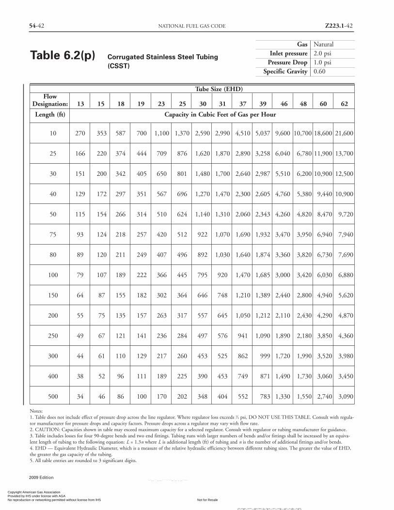
54-42 NATIONAL FUEL GAS CODE Z223.1-42
Gas NaturalInlet pressure 2.0 psi
Pressure Drop 1.0 psiSpecific Gravity 0.60
Tube Size (EHD)Flow
Designation: 13 15 18 19 23 25 30 31 37 39 46 48 60 62
Length (ft) Capacity in Cubic Feet of Gas per Hour
10 270 353 587 700 1,100 1,370 2,590 2,990 4,510 5,037 9,600 10,700 18,600 21,600
25 166 220 374 444 709 876 1,620 1,870 2,890 3,258 6,040 6,780 11,900 13,700
30 151 200 342 405 650 801 1,480 1,700 2,640 2,987 5,510 6,200 10,900 12,500
40 129 172 297 351 567 696 1,270 1,470 2,300 2,605 4,760 5,380 9,440 10,900
50 115 154 266 314 510 624 1,140 1,310 2,060 2,343 4,260 4,820 8,470 9,720
75 93 124 218 257 420 512 922 1,070 1,690 1,932 3,470 3,950 6,940 7,940
80 89 120 211 249 407 496 892 1,030 1,640 1,874 3,360 3,820 6,730 7,690
100 79 107 189 222 366 445 795 920 1,470 1,685 3,000 3,420 6,030 6,880
150 64 87 155 182 302 364 646 748 1,210 1,389 2,440 2,800 4,940 5,620
200 55 75 135 157 263 317 557 645 1,050 1,212 2,110 2,430 4,290 4,870
250 49 67 121 141 236 284 497 576 941 1,090 1,890 2,180 3,850 4,360
300 44 61 110 129 217 260 453 525 862 999 1,720 1,990 3,520 3,980
400 38 52 96 111 189 225 390 453 749 871 1,490 1,730 3,060 3,450
500 34 46 86 100 170 202 348 404 552 783 1,330 1,550 2,740 3,090
Notes:1. Table does not include effect of pressure drop across the line regulator. Where regulator loss exceeds 3⁄4 psi, DO NOT USE THIS TABLE. Consult with regula-tor manufacturer for pressure drops and capacity factors. Pressure drops across a regulator may vary with flow rate.2. CAUTION: Capacities shown in table may exceed maximum capacity for a selected regulator. Consult with regulator or tubing manufacturer for guidance.3. Table includes losses for four 90-degree bends and two end fittings. Tubing runs with larger numbers of bends and/or fittings shall be increased by an equiva-lent length of tubing to the following equation: L = 1.3n where L is additional length (ft) of tubing and n is the number of additional fittings and/or bends.4. EHD — Equivalent Hydraulic Diameter, which is a measure of the relative hydraulic efficiency between different tubing sizes. The greater the value of EHD,the greater the gas capacity of the tubing.5. All table entries are rounded to 3 significant digits.
Table 6.2(p) Corrugated Stainless Steel Tubing(CSST)
2009 Edition
Copyright American Gas Association Provided by IHS under license with AGA
Not for ResaleNo reproduction or networking permitted without license from IHS
--`,,```,,,,````-`-`,,`,,`,`,,`---
//^:^^#^~^^""~:@":^*^~$~"#:*~::*^~:^^#~~#^~:^:@:~*:$"\\

Z223.1-43 PIPE SIZING 54-43
2009 Edition
Gas NaturalInlet pressure 5.0 psi
Pressure Drop 3.5 psiSpecific Gravity 0.60
Tube Size (EHD)Flow
Designation: 13 15 18 19 23 25 30 31 37 39 46 48 60 62
Length (ft) Capacity in Cubic Feet of Gas per Hour
10 523 674 1,080 1,300 2,000 2,530 4,920 5,660 8,300 9,140 18,100 19,800 34,400 40,400
25 322 420 691 827 1,290 1,620 3,080 3,540 5,310 5,911 11,400 12,600 22,000 25,600
30 292 382 632 755 1,180 1,480 2,800 3,230 4,860 5,420 10,400 11,500 20,100 23,400
40 251 329 549 654 1,030 1,280 2,420 2,790 4,230 4,727 8,970 10,000 17,400 20,200
50 223 293 492 586 926 1,150 2,160 2,490 3,790 4,251 8,020 8,930 15,600 18,100
75 180 238 403 479 763 944 1,750 2,020 3,110 3,506 6,530 7,320 12,800 14,800
80 174 230 391 463 740 915 1,690 1,960 3,020 3,400 6,320 7,090 12,400 14,300
100 154 205 350 415 665 820 1,510 1,740 2,710 3,057 5,650 6,350 11,100 12,800
150 124 166 287 339 548 672 1,230 1,420 2,220 2,521 4,600 5,200 9,130 10,500
200 107 143 249 294 478 584 1,060 1,220 1,930 2,199 3,980 4,510 7,930 9,090
250 95 128 223 263 430 524 945 1,090 1,730 1,977 3,550 4,040 7,110 8,140
300 86 116 204 240 394 479 860 995 1,590 1,813 3,240 3,690 6,500 7,430
400 74 100 177 208 343 416 742 858 1,380 1,581 2,800 3,210 5,650 6,440
500 66 89 159 186 309 373 662 766 1,040 1,422 2,500 2,870 5,060 5,760
Notes:1. Table does not include effect of pressure drop across the line regulator. Where regulator loss exceeds 3⁄4 psi, DO NOT USE THIS TABLE. Consult with regula-tor manufacturer for pressure drops and capacity factors. Pressure drops across a regulator may vary with flow rate.2. CAUTION: Capacities shown in table may exceed maximum capacity for a selected regulator. Consult with regulator or tubing manufacturer for guidance.3. Table includes losses for four 90-degree bends and two end fittings. Tubing runs with larger numbers of bends and/or fittings shall be increased by an equiva-lent length of tubing to the following equation: L = 1.3n where L is additional length (ft) of tubing and n is the number of additional fittings and/or bends.4. EHD — Equivalent Hydraulic Diameter, which is a measure of the relative hydraulic efficiency between different tubing sizes. The greater the value of EHD,the greater the gas capacity of the tubing.5. All table entries are rounded to 3 significant digits.
Table 6.2(q) Corrugated Stainless Steel Tubing(CSST)
Copyright American Gas Association Provided by IHS under license with AGA
Not for ResaleNo reproduction or networking permitted without license from IHS
--`,,```,,,,````-`-`,,`,,`,`,,`---
//^:^
^#^~
^^""
~:@
":^*^
~$~"
#:*~
::*^~
:^^#
~~#^
~:^:
@:~
*:$"
\\

54-44 NATIONAL FUEL GAS CODE Z223.1-44
Gas NaturalInlet pressure Less than 2 psi
Pressure Drop 0.3 in. w.c.Specific Gravity 0.60
Pipe Size (in.)Nominal OD: 1⁄2 3⁄4 1 11⁄4 11⁄2 2Designation: SDR 9.33 SDR 11.0 SDR 11.00 SDR 10.00 SDR 11.00 SDR 11.00Actual ID: 0.660 0.860 1.077 1.328 1.554 1.943
Length (ft) Capacity in Cubic Feet of Gas per Hour
10 153 305 551 955 1,440 2,590
20 105 210 379 656 991 1,780
30 84 169 304 527 796 1,430
40 72 144 260 451 681 1,220
50 64 128 231 400 604 1,080
60 58 116 209 362 547 983
70 53 107 192 333 503 904
80 50 99 179 310 468 841
90 46 93 168 291 439 789
100 44 88 159 275 415 745
125 39 78 141 243 368 661
150 35 71 127 221 333 598
175 32 65 117 203 306 551
200 30 60 109 189 285 512
250 27 54 97 167 253 454
300 24 48 88 152 229 411
350 22 45 81 139 211 378
400 21 42 75 130 196 352
450 19 39 70 122 184 330
500 18 37 66 115 174 312
Note: All table entries are rounded to 3 significant digits.
Table 6.2(r) Polyethylene Plastic Pipe
2009 Edition
Copyright American Gas Association Provided by IHS under license with AGA
Not for ResaleNo reproduction or networking permitted without license from IHS
--`,,```,,,,````-`-`,,`,,`,`,,`---
//^:^^#^~^^""~:@":^*^~$~"#:*~::*^~:^^#~~#^~:^:@
:~*:$"\\
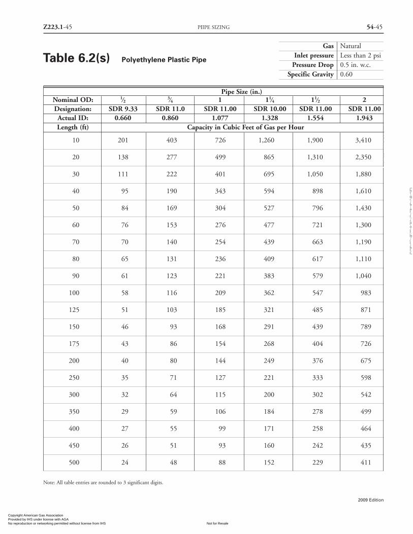
Z223.1-45 PIIPE SIZING 54-45
2009 Edition
Gas NaturalInlet pressure Less than 2 psi
Pressure Drop 0.5 in. w.c.Specific Gravity 0.60
Pipe Size (in.)Nominal OD: 1⁄2 3⁄4 1 11⁄4 11⁄2 2Designation: SDR 9.33 SDR 11.0 SDR 11.00 SDR 10.00 SDR 11.00 SDR 11.00Actual ID: 0.660 0.860 1.077 1.328 1.554 1.943Length (ft) Capacity in Cubic Feet of Gas per Hour
10 201 403 726 1,260 1,900 3,410
20 138 277 499 865 1,310 2,350
30 111 222 401 695 1,050 1,880
40 95 190 343 594 898 1,610
50 84 169 304 527 796 1,430
60 76 153 276 477 721 1,300
70 70 140 254 439 663 1,190
80 65 131 236 409 617 1,110
90 61 123 221 383 579 1,040
100 58 116 209 362 547 983
125 51 103 185 321 485 871
150 46 93 168 291 439 789
175 43 86 154 268 404 726
200 40 80 144 249 376 675
250 35 71 127 221 333 598
300 32 64 115 200 302 542
350 29 59 106 184 278 499
400 27 55 99 171 258 464
450 26 51 93 160 242 435
500 24 48 88 152 229 411
Note: All table entries are rounded to 3 significant digits.
Table 6.2(s) Polyethylene Plastic Pipe
Copyright American Gas Association Provided by IHS under license with AGA
Not for ResaleNo reproduction or networking permitted without license from IHS
--`,,```,,,,````-`-`,,`,,`,`,,`---
//^:^
^#^~
^^""
~:@
":^*^
~$~"
#:*~
::*^~
:^^#
~~#^
~:^:
@:~
*:$"
\\

54-46 NATIONAL FUEL GAS CODE Z223.1-46
Gas NaturalInlet pressure 2.0 psi
Pressure Drop 1.0 psiSpecific Gravity 0.60
Pipe Size (in.)Nominal OD: 1⁄2 3⁄4 1 11⁄4 11⁄2 2Designation: SDR 9.33 SDR 11.0 SDR 11.00 SDR 10.00 SDR 11.00 SDR 11.00Actual ID: 0.660 0.860 1.077 1.328 1.554 1.943Length (ft) Capacity in Cubic Feet of Gas per Hour
10 1,860 3,720 6,710 11,600 17,600 31,60020 1,280 2,560 4,610 7,990 12,100 21,70030 1,030 2,050 3,710 6,420 9,690 17,40040 878 1,760 3,170 5,490 8,300 14,90050 778 1,560 2,810 4,870 7,350 13,20060 705 1,410 2,550 4,410 6,660 12,00070 649 1,300 2,340 4,060 6,130 11,00080 603 1,210 2,180 3,780 5,700 10,20090 566 1,130 2,050 3,540 5,350 9,610
100 535 1,070 1,930 3,350 5,050 9,080125 474 949 1,710 2,970 4,480 8,050150 429 860 1,550 2,690 4,060 7,290175 395 791 1,430 2,470 3,730 6,710200 368 736 1,330 2,300 3,470 6,240250 326 652 1,180 2,040 3,080 5,530300 295 591 1,070 1,850 2,790 5,010350 272 544 981 1,700 2,570 4,610400 253 506 913 1,580 2,390 4,290450 237 475 856 1,480 2,240 4,020500 224 448 809 1,400 2,120 3,800550 213 426 768 1,330 2,010 3,610600 203 406 733 1,270 1,920 3,440650 194 389 702 1,220 1,840 3,300700 187 374 674 1,170 1,760 3,170750 180 360 649 1,130 1,700 3,050800 174 348 627 1,090 1,640 2,950850 168 336 607 1,050 1,590 2,850900 163 326 588 1,020 1,540 2,770950 158 317 572 990 1,500 2,690
1,000 154 308 556 963 1,450 2,6101,100 146 293 528 915 1,380 2,4801,200 139 279 504 873 1,320 2,3701,300 134 267 482 836 1,260 2,2701,400 128 257 463 803 1,210 2,1801,500 124 247 446 773 1,170 2,1001,600 119 239 431 747 1,130 2,0301,700 115 231 417 723 1,090 1,9601,800 112 224 404 701 1,060 1,9001,900 109 218 393 680 1,030 1,8502,000 106 212 382 662 1,000 1,800
Note: All table entries are rounded to 3 significant digits.
Table 6.2(t) Polyethylene Plastic Pipe
2009 Edition
Copyright American Gas Association Provided by IHS under license with AGA
Not for ResaleNo reproduction or networking permitted without license from IHS
--`,,```,,,,````-`-`,,`,,`,`,,`---
//^:^^#^~^^""~:@":^*^~$~"#:*~::*^~:^^#~~#^~:^:@:~*:$"\\

Z223.1-47 PIPE SIZING 54-47
2009 Edition
Gas NaturalInlet pressure Less than 2.0 psi
Pressure Drop 0.3 in. w.c.Specific Gravity 0.60
Plastic Tubing Size (CTS) (in.)Nominal OD: 1⁄2 1Designation: SDR 7.00 SDR 11.00Actual ID: 0.445 0.927
Length Capacity in(ft) Cubic Feet of Gas per Hour
10 54 372
20 37 256
30 30 205
40 26 176
50 23 156
60 21 141
70 19 130
80 18 121
90 17 113
100 16 107
125 14 95
150 13 86
175 12 79
200 11 74
225 10 69
250 NA 65
275 NA 62
300 NA 59
350 NA 54
400 NA 51
450 NA 47
500 NA 45
Notes:1. NA means a flow of less than 10 cfh2. All table entries are rounded to 3 significant digits.
Table 6.2(u) Polyethylene PlasticTubing
Gas NaturalInlet pressure Less than 2.0 psi
Pressure Drop 0.5 in. w.c.Specific Gravity 0.60
Plastic Tubing Size (CTS) (in.)Nominal OD: 1⁄2 1Designation: SDR 7.00 SDR 11.00Actual ID: 0.445 0.927
Length Capacity in(ft) Cubic Feet of Gas per Hour
10 72 490
20 49 337
30 39 271
40 34 232
50 30 205
60 27 186
70 25 171
80 23 159
90 22 149
100 21 141
125 18 125
150 17 113
175 15 104
200 14 97
225 13 91
250 12 86
275 11 82
300 11 78
350 10 72
400 NA 67
450 NA 63
500 NA 59
Notes:1. NA means a flow of less than 10 cfh2. All table entries are rounded to 3 significant digits.
Table 6.2(v) Polyethylene PlasticTubing
Copyright American Gas Association Provided by IHS under license with AGA
Not for ResaleNo reproduction or networking permitted without license from IHS
--`,,```,,,,````-`-`,,`,,`,`,,`---
//^:^
^#^~
^^""
~:@
":^*^
~$~"
#:*~
::*^~
:^^#
~~#^
~:^:
@:~
*:$"
\\
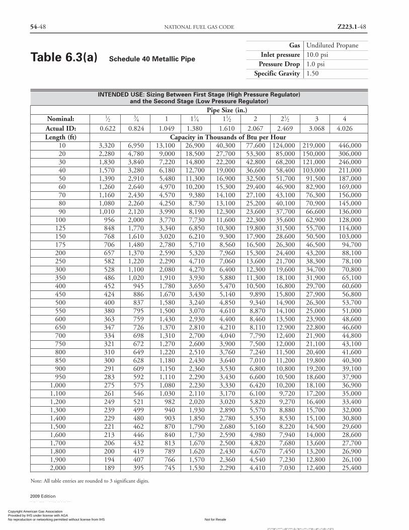
54-48 NATIONAL FUEL GAS CODE Z223.1-48
INTENDED USE: Sizing Between First Stage (High Pressure Regulator)and the Second Stage (Low Pressure Regulator)
Pipe Size (in.)Nominal: 1⁄2 3⁄4 1 11⁄4 11⁄2 2 21⁄2 3 4Actual ID: 0.622 0.824 1.049 1.380 1.610 2.067 2.469 3.068 4.026Length (ft) Capacity in Thousands of Btu per Hour
10 3,320 6,950 13,100 26,900 40,300 77,600 124,000 219,000 446,00020 2,280 4,780 9,000 18,500 27,700 53,300 85,000 150,000 306,00030 1,830 3,840 7,220 14,800 22,200 42,800 68,200 121,000 246,00040 1,570 3,280 6,180 12,700 19,000 36,600 58,400 103,000 211,00050 1,390 2,910 5,480 11,300 16,900 32,500 51,700 91,500 187,00060 1,260 2,640 4,970 10,200 15,300 29,400 46,900 82,900 169,00070 1,160 2,430 4,570 9,380 14,100 27,100 43,100 76,300 156,00080 1,080 2,260 4,250 8,730 13,100 25,200 40,100 70,900 145,00090 1,010 2,120 3,990 8,190 12,300 23,600 37,700 66,600 136,000
100 956 2,000 3,770 7,730 11,600 22,300 35,600 62,900 128,000125 848 1,770 3,340 6,850 10,300 19,800 31,500 55,700 114,000150 768 1,610 3,020 6,210 9,300 17,900 28,600 50,500 103,000175 706 1,480 2,780 5,710 8,560 16,500 26,300 46,500 94,700200 657 1,370 2,590 5,320 7,960 15,300 24,400 43,200 88,100250 582 1,220 2,290 4,710 7,060 13,600 21,700 38,300 78,100300 528 1,100 2,080 4,270 6,400 12,300 19,600 34,700 70,800350 486 1,020 1,910 3,930 5,880 11,300 18,100 31,900 65,100400 452 945 1,780 3,650 5,470 10,500 16,800 29,700 60,600450 424 886 1,670 3,430 5,140 9,890 15,800 27,900 56,800500 400 837 1,580 3,240 4,850 9,340 14,900 26,300 53,700550 380 795 1,500 3,070 4,610 8,870 14,100 25,000 51,000600 363 759 1,430 2,930 4,400 8,460 13,500 23,900 48,600650 347 726 1,370 2,810 4,210 8,110 12,900 22,800 46,600700 334 698 1,310 2,700 4,040 7,790 12,400 21,900 44,800750 321 672 1,270 2,600 3,900 7,500 12,000 21,100 43,100800 310 649 1,220 2,510 3,760 7,240 11,500 20,400 41,600850 300 628 1,180 2,430 3,640 7,010 11,200 19,800 40,300900 291 609 1,150 2,360 3,530 6,800 10,800 19,200 39,100950 283 592 1,110 2,290 3,430 6,600 10,500 18,600 37,900
1,000 275 575 1,080 2,230 3,330 6,420 10,200 18,100 36,9001,100 261 546 1,030 2,110 3,170 6,100 9,720 17,200 35,0001,200 249 521 982 2,020 3,020 5,820 9,270 16,400 33,4001,300 239 499 940 1,930 2,890 5,570 8,880 15,700 32,0001,400 229 480 903 1,850 2,780 5,350 8,530 15,100 30,8001,500 221 462 870 1,790 2,680 5,160 8,220 14,500 29,6001,600 213 446 840 1,730 2,590 4,980 7,940 14,000 28,6001,700 206 432 813 1,670 2,500 4,820 7,680 13,600 27,7001,800 200 419 789 1,620 2,430 4,670 7,450 13,200 26,9001,900 194 407 766 1,570 2,360 4,540 7,230 12,800 26,1002,000 189 395 745 1,530 2,290 4,410 7,030 12,400 25,400
Note: All table entries are rounded to 3 significant digits.
Gas Undiluted PropaneInlet pressure 10.0 psi
Pressure Drop 1.0 psiSpecific Gravity 1.50
Table 6.3(a) Schedule 40 Metallic Pipe
2009 Edition
Copyright American Gas Association Provided by IHS under license with AGA
Not for ResaleNo reproduction or networking permitted without license from IHS
--`,,```,,,,````-`-`,,`,,`,`,,`---
//^:^^#^~^^""~:@":^*^~$~"#:*~::*^~:^^#~~#^~:^:@:~*:$"\\

Z223.1-49 PIPE SIZING 54-49
2009 Edition
INTENDED USE: Sizing Between First Stage (High Pressure Regulator)and the Second Stage (Low Pressure Regulator)
Pipe Size (in.)Nominal: 1⁄2 3⁄4 1 11⁄4 11⁄2 2 21⁄2 3 4Actual ID: 0.622 0.824 1.049 1.380 1.610 2.067 2.469 3.068 4.026Length (ft) Capacity in Thousands of Btu per Hour
10 5,890 12,300 23,200 47,600 71,300 137,000 219,000 387,000 789,00020 4,050 8,460 15,900 32,700 49,000 94,400 150,000 266,000 543,00030 3,250 6,790 12,800 26,300 39,400 75,800 121,000 214,000 436,00040 2,780 5,810 11,000 22,500 33,700 64,900 103,000 183,000 373,00050 2,460 5,150 9,710 19,900 29,900 57,500 91,600 162,000 330,00060 2,230 4,670 8,790 18,100 27,100 52,100 83,000 147,000 299,00070 2,050 4,300 8,090 16,600 24,900 47,900 76,400 135,000 275,00080 1,910 4,000 7,530 15,500 23,200 44,600 71,100 126,000 256,00090 1,790 3,750 7,060 14,500 21,700 41,800 66,700 118,000 240,000
100 1,690 3,540 6,670 13,700 20,500 39,500 63,000 111,000 227,000125 1,500 3,140 5,910 12,100 18,200 35,000 55,800 98,700 201,000150 1,360 2,840 5,360 11,000 16,500 31,700 50,600 89,400 182,000175 1,250 2,620 4,930 10,100 15,200 29,200 46,500 82,300 167,800200 1,160 2,430 4,580 9,410 14,100 27,200 43,300 76,500 156,100250 1,030 2,160 4,060 8,340 12,500 24,100 38,400 67,800 138,400300 935 1,950 3,680 7,560 11,300 21,800 34,800 61,500 125,400350 860 1,800 3,390 6,950 10,400 20,100 32,000 56,500 115,300400 800 1,670 3,150 6,470 9,690 18,700 29,800 52,600 107,300450 751 1,570 2,960 6,070 9,090 17,500 27,900 49,400 100,700500 709 1,480 2,790 5,730 8,590 16,500 26,400 46,600 95,100550 673 1,410 2,650 5,450 8,160 15,700 25,000 44,300 90,300600 642 1,340 2,530 5,200 7,780 15,000 23,900 42,200 86,200650 615 1,290 2,420 4,980 7,450 14,400 22,900 40,500 82,500700 591 1,240 2,330 4,780 7,160 13,800 22,000 38,900 79,300750 569 1,190 2,240 4,600 6,900 13,300 21,200 37,400 76,400800 550 1,150 2,170 4,450 6,660 12,800 20,500 36,200 73,700850 532 1,110 2,100 4,300 6,450 12,400 19,800 35,000 71,400900 516 1,080 2,030 4,170 6,250 12,000 19,200 33,900 69,200950 501 1,050 1,970 4,050 6,070 11,700 18,600 32,900 67,200
1,000 487 1,020 1,920 3,940 5,900 11,400 18,100 32,000 65,4001,100 463 968 1,820 3,740 5,610 10,800 17,200 30,400 62,1001,200 442 923 1,740 3,570 5,350 10,300 16,400 29,000 59,2001,300 423 884 1,670 3,420 5,120 9,870 15,700 27,800 56,7001,400 406 849 1,600 3,280 4,920 9,480 15,100 26,700 54,5001,500 391 818 1,540 3,160 4,740 9,130 14,600 25,700 52,5001,600 378 790 1,490 3,060 4,580 8,820 14,100 24,800 50,7001,700 366 765 1,440 2,960 4,430 8,530 13,600 24,000 49,0001,800 355 741 1,400 2,870 4,300 8,270 13,200 23,300 47,6001,900 344 720 1,360 2,780 4,170 8,040 12,800 22,600 46,2002,000 335 700 1,320 2,710 4,060 7,820 12,500 22,000 44,900
Note: All table entries are rounded to 3 significant digits.
Gas Undiluted PropaneInlet pressure 10.0 psi
Pressure Drop 3.0 psiSpecific Gravity 1.50
Table 6.3(b) Schedule 40 Metallic Pipe
Copyright American Gas Association Provided by IHS under license with AGA
Not for ResaleNo reproduction or networking permitted without license from IHS
--`,,```,,,,````-`-`,,`,,`,`,,`---
//^:^^#^~^^""~:@":^*^~$~"#:*~::*^~:^^#~~#^~:^:@
:~*:$"\\

54-50 NATIONAL FUEL GAS CODE Z223.1-50
Gas Undiluted PropaneInlet pressure 2.0 psi
Pressure Drop 1.0 psiSpecific Gravity 1.50
INTENDED USE: Sizing Between 2 psi Service and the Line Pressure RegulatorPipe Size (in.)
Nominal: 1⁄2 3⁄4 1 11⁄4 11⁄2 2 21⁄2 3 4Actual ID: 0.622 0.824 1.049 1.380 1.610 2.067 2.469 3.068 4.026Length (ft) Capacity in Thousands of Btu per Hour
10 2,680 5,590 10,500 21,600 32,400 62,400 99,500 176,000 359,00020 1,840 3,850 7,240 14,900 22,300 42,900 68,400 121,000 247,00030 1,480 3,090 5,820 11,900 17,900 34,500 54,900 97,100 198,00040 1,260 2,640 4,980 10,200 15,300 29,500 47,000 83,100 170,00050 1,120 2,340 4,410 9,060 13,600 26,100 41,700 73,700 150,00060 1,010 2,120 4,000 8,210 12,300 23,700 37,700 66,700 136,00070 934 1,950 3,680 7,550 11,300 21,800 34,700 61,400 125,00080 869 1,820 3,420 7,020 10,500 20,300 32,300 57,100 116,00090 815 1,700 3,210 6,590 9,880 19,000 30,300 53,600 109,000
100 770 1,610 3,030 6,230 9,330 18,000 28,600 50,600 103,000125 682 1,430 2,690 5,520 8,270 15,900 25,400 44,900 91,500150 618 1,290 2,440 5,000 7,490 14,400 23,000 40,700 82,900175 569 1,190 2,240 4,600 6,890 13,300 21,200 37,400 76,300200 529 1,110 2,080 4,280 6,410 12,300 19,700 34,800 71,000250 469 981 1,850 3,790 5,680 10,900 17,400 30,800 62,900300 425 889 1,670 3,440 5,150 9,920 15,800 27,900 57,000350 391 817 1,540 3,160 4,740 9,120 14,500 25,700 52,400400 364 760 1,430 2,940 4,410 8,490 13,500 23,900 48,800450 341 714 1,340 2,760 4,130 7,960 12,700 22,400 45,800500 322 674 1,270 2,610 3,910 7,520 12,000 21,200 43,200550 306 640 1,210 2,480 3,710 7,140 11,400 20,100 41,100600 292 611 1,150 2,360 3,540 6,820 10,900 19,200 39,200650 280 585 1,100 2,260 3,390 6,530 10,400 18,400 37,500700 269 562 1,060 2,170 3,260 6,270 9,990 17,700 36,000750 259 541 1,020 2,090 3,140 6,040 9,630 17,000 34,700800 250 523 985 2,020 3,030 5,830 9,300 16,400 33,500850 242 506 953 1,960 2,930 5,640 9,000 15,900 32,400900 235 490 924 1,900 2,840 5,470 8,720 15,400 31,500950 228 476 897 1,840 2,760 5,310 8,470 15,000 30,500
1,000 222 463 873 1,790 2,680 5,170 8,240 14,600 29,7001,100 210 440 829 1,700 2,550 4,910 7,830 13,800 28,2001,200 201 420 791 1,620 2,430 4,680 7,470 13,200 26,9001,300 192 402 757 1,550 2,330 4,490 7,150 12,600 25,8001,400 185 386 727 1,490 2,240 4,310 6,870 12,100 24,8001,500 178 372 701 1,440 2,160 4,150 6,620 11,700 23,9001,600 172 359 677 1,390 2,080 4,010 6,390 11,300 23,0001,700 166 348 655 1,340 2,010 3,880 6,180 10,900 22,3001,800 161 337 635 1,300 1,950 3,760 6,000 10,600 21,6001,900 157 327 617 1,270 1,900 3,650 5,820 10,300 21,0002,000 152 318 600 1,230 1,840 3,550 5,660 10,000 20,400
Note: All table entries are rounded to 3 significant digits.
Table 6.3(c) Schedule 40 Metallic Pipe
2009 Edition
Copyright American Gas Association Provided by IHS under license with AGA
Not for ResaleNo reproduction or networking permitted without license from IHS
--`,,```,,,,````-`-`,,`,,`,`,,`---
//^:^^#^~^^""~:@":^*^~$~"#:*~::*^~:^^#~~#^~:^:@:~*:$"\\

Z223.1-51 PIPE SIZING 54-51
2009 Edition
INTENDED USE: Sizing Between Single or Second Stage (Low Pressure Regulator) and the AppliancePipe Size (in.)
Nominal: 1⁄2 3⁄4 1 11⁄4 11⁄2 2 21⁄2 3 4Actual ID: 0.622 0.824 1.049 1.380 1.610 2.067 2.469 3.068 4.026Length (ft) Capacity in Thousands of Btu per Hour
10 291 608 1,150 2,350 3,520 6,790 10,800 19,100 39,00020 200 418 787 1,620 2,420 4,660 7,430 13,100 26,80030 160 336 632 1,300 1,940 3,750 5,970 10,600 21,50040 137 287 541 1,110 1,660 3,210 5,110 9,030 18,40050 122 255 480 985 1,480 2,840 4,530 8,000 16,30060 110 231 434 892 1,340 2,570 4,100 7,250 14,80080 101 212 400 821 1,230 2,370 3,770 6,670 13,600
100 94 197 372 763 1,140 2,200 3,510 6,210 12,700125 89 185 349 716 1,070 2,070 3,290 5,820 11,900150 84 175 330 677 1,010 1,950 3,110 5,500 11,200175 74 155 292 600 899 1,730 2,760 4,880 9,950200 67 140 265 543 814 1,570 2,500 4,420 9,010250 62 129 243 500 749 1,440 2,300 4,060 8,290300 58 120 227 465 697 1,340 2,140 3,780 7,710350 51 107 201 412 618 1,190 1,900 3,350 6,840400 46 97 182 373 560 1,080 1,720 3,040 6,190450 42 89 167 344 515 991 1,580 2,790 5,700500 40 83 156 320 479 922 1,470 2,600 5,300550 37 78 146 300 449 865 1,380 2,440 4,970600 35 73 138 283 424 817 1,300 2,300 4,700650 33 70 131 269 403 776 1,240 2,190 4,460700 32 66 125 257 385 741 1,180 2,090 4,260750 30 64 120 246 368 709 1,130 2,000 4,080800 29 61 115 236 354 681 1,090 1,920 3,920850 28 59 111 227 341 656 1,050 1,850 3,770900 27 57 107 220 329 634 1,010 1,790 3,640950 26 55 104 213 319 613 978 1,730 3,530
1,000 25 53 100 206 309 595 948 1,680 3,4201,100 25 52 97 200 300 578 921 1,630 3,3201,200 24 50 95 195 292 562 895 1,580 3,2301,300 23 48 90 185 277 534 850 1,500 3,0701,400 22 46 86 176 264 509 811 1,430 2,9301,500 21 44 82 169 253 487 777 1,370 2,8001,600 20 42 79 162 243 468 746 1,320 2,6901,700 19 40 76 156 234 451 719 1,270 2,5901,800 19 39 74 151 226 436 694 1,230 2,5001,900 18 38 71 146 219 422 672 1,190 2,4202,000 18 37 69 142 212 409 652 1,150 2,350
Note: All table entries are rounded to 3 significant digits.
Gas Undiluted PropaneInlet pressure 11.0 in. w.c.
Pressure Drop 0.5 in. w.c.Specific Gravity 1.50
Table 6.3(d) Schedule 40 Metallic Pipe
Copyright American Gas Association Provided by IHS under license with AGA
Not for ResaleNo reproduction or networking permitted without license from IHS
--`,,```,,,,````-`-`,,`,,`,`,,`---
//^:^^#^~^^""~:@":^*^~$~"#:*~::*^~:^^#~~#^~:^:@
:~*:$"\\

54-52 NATIONAL FUEL GAS CODE Z223.1-52
Gas Undiluted PropaneInlet pressure 10.0 psi
Pressure Drop 1.0 psiSpecific Gravity 1.50
INTENDED USE: Sizing Between First Stage (High Presssure Regulator)and the Second Stage (Low Presssure Regulator)
Tube Size (in.)
Nominal:K & L 1⁄4 3⁄8 1⁄2 5⁄8 3⁄4 1 11⁄4 11⁄2 2ACR 3⁄8 1⁄2 5⁄8 3⁄4 7⁄8 11⁄8 13⁄8 – –
Outside: 0.375 0.500 0.625 0.750 0.875 1.125 1.375 1.625 2.125Inside: 0.305 0.402 0.527 0.652 0.745 0.995 1.245 1.481 1.959
Length (ft) Capacity in Thousands of Btu per Hour10 513 1,060 2,150 3,760 5,330 11,400 20,500 32,300 67,40020 352 727 1,480 2,580 3,670 7,830 14,100 22,200 46,30030 283 584 1,190 2,080 2,940 6,290 11,300 17,900 37,20040 242 500 1,020 1,780 2,520 5,380 9,690 15,300 31,80050 215 443 901 1,570 2,230 4,770 8,590 13,500 28,20060 194 401 816 1,430 2,020 4,320 7,780 12,300 25,60070 179 369 751 1,310 1,860 3,980 7,160 11,300 23,50080 166 343 699 1,220 1,730 3,700 6,660 10,500 21,90090 156 322 655 1,150 1,630 3,470 6,250 9,850 20,500100 147 304 619 1,080 1,540 3,280 5,900 9,310 19,400125 131 270 549 959 1,360 2,910 5,230 8,250 17,200150 118 244 497 869 1,230 2,630 4,740 7,470 15,600175 109 225 457 799 1,130 2,420 4,360 6,880 14,300200 101 209 426 744 1,060 2,250 4,060 6,400 13,300250 90 185 377 659 935 2,000 3,600 5,670 11,800300 81 168 342 597 847 1,810 3,260 5,140 10,700350 75 155 314 549 779 1,660 3,000 4,730 9,840400 70 144 292 511 725 1,550 2,790 4,400 9,160450 65 135 274 480 680 1,450 2,620 4,130 8,590500 62 127 259 453 643 1,370 2,470 3,900 8,120550 59 121 246 430 610 1,300 2,350 3,700 7,710600 56 115 235 410 582 1,240 2,240 3,530 7,350650 54 111 225 393 558 1,190 2,140 3,380 7,040700 51 106 216 378 536 1,140 2,060 3,250 6,770750 50 102 208 364 516 1,100 1,980 3,130 6,520800 48 99 201 351 498 1,060 1,920 3,020 6,290850 46 96 195 340 482 1,030 1,850 2,920 6,090900 45 93 189 330 468 1,000 1,800 2,840 5,910950 44 90 183 320 454 970 1,750 2,750 5,730
1,000 42 88 178 311 442 944 1,700 2,680 5,5801,100 40 83 169 296 420 896 1,610 2,540 5,3001,200 38 79 161 282 400 855 1,540 2,430 5,0501,300 37 76 155 270 383 819 1,470 2,320 4,8401,400 35 73 148 260 368 787 1,420 2,230 4,6501,500 34 70 143 250 355 758 1,360 2,150 4,4801,600 33 68 138 241 343 732 1,320 2,080 4,3301,700 32 66 134 234 331 708 1,270 2,010 4,1901,800 31 64 130 227 321 687 1,240 1,950 4,0601,900 30 62 126 220 312 667 1,200 1,890 3,9402,000 29 60 122 214 304 648 1,170 1,840 3,830
Notes:
1. Table capacities are based on Type K copper tubing inside diameter (shown), which has the smallest inside diameter of the copper tubing products.2. All table entries are rounded to 3 significant digits.
Table 6.3(e) Semi-Rigid Copper Tubing
2009 Edition
Copyright American Gas Association Provided by IHS under license with AGA
Not for ResaleNo reproduction or networking permitted without license from IHS
--`,,```,,,,````-`-`,,`,,`,`,,`---
//^:^^#^~^^""~:@":^*^~$~"#:*~::*^~:^^#~~#^~:^:@:~*:$"\\

Z223.1-53 PIPE SIZING 54-53
2009 Edition
Gas Undiluted PropaneInlet pressure 11.0 in. w.c.
Pressure Drop 0.5 in. w.c.Specific Gravity 1.50
INTENDED USE: Sizing Between Single or Second Stage (Low Pressure Regulator) and the ApplianceTube Size (in.)
Nominal:K & L 1⁄4 3⁄8 1⁄2 5⁄8 3⁄4 1 11⁄4 11⁄2 2ACR 3⁄8 1⁄2 5⁄8 3⁄4 7⁄8 11⁄8 13⁄8 – –
Outside: 0.375 0.500 0.625 0.750 0.875 1.125 1.375 1.625 2.125Inside: 0.305 0.402 0.527 0.652 0.745 0.995 1.245 1.481 1.959
Length (ft) Capacity in Thousands of Btu per Hour10 45 93 188 329 467 997 1,800 2,830 5,89020 31 64 129 226 321 685 1,230 1,950 4,05030 25 51 104 182 258 550 991 1,560 3,25040 21 44 89 155 220 471 848 1,340 2,78050 19 39 79 138 195 417 752 1,180 2,47060 17 35 71 125 177 378 681 1,070 2,24070 16 32 66 115 163 348 626 988 2,06080 15 30 61 107 152 324 583 919 1,91090 14 28 57 100 142 304 547 862 1,800100 13 27 54 95 134 287 517 814 1,700125 11 24 48 84 119 254 458 722 1,500150 10 21 44 76 108 230 415 654 1,360175 NA 20 40 70 99 212 382 602 1,250200 NA 18 37 65 92 197 355 560 1,170250 NA 16 33 58 82 175 315 496 1,030300 NA 15 30 52 74 158 285 449 936350 NA 14 28 48 68 146 262 414 861400 NA 13 26 45 63 136 244 385 801450 NA 12 24 42 60 127 229 361 752500 NA 11 23 40 56 120 216 341 710550 NA 11 22 38 53 114 205 324 674600 NA 10 21 36 51 109 196 309 643650 NA NA 20 34 49 104 188 296 616700 NA NA 19 33 47 100 180 284 592750 NA NA 18 32 45 96 174 274 570800 NA NA 18 31 44 93 168 264 551850 NA NA 17 30 42 90 162 256 533900 NA NA 17 29 41 87 157 248 517950 NA NA 16 28 40 85 153 241 502
1,000 NA NA 16 27 39 83 149 234 4881,100 NA NA 15 26 37 78 141 223 4641,200 NA NA 14 25 35 75 135 212 4421,300 NA NA 14 24 34 72 129 203 4231,400 NA NA 13 23 32 69 124 195 4071,500 NA NA 13 22 31 66 119 188 3921,600 NA NA 12 21 30 64 115 182 3781,700 NA NA 12 20 29 62 112 176 3661,800 NA NA 11 20 28 60 108 170 3551,900 NA NA 11 19 27 58 105 166 3452,000 NA NA 11 19 27 57 102 161 335
Notes:1. Table capacities are based on Type K copper tubing inside diameter (shown), which has the smallest inside diameter of the copper tubing products.2. NA means a flow of less than 10,000 But/hr3. All table entries are rounded to 3 significant digits.
Table 6.3(f) Semi-Rigid Copper Tubing
Copyright American Gas Association Provided by IHS under license with AGA
Not for ResaleNo reproduction or networking permitted without license from IHS
--`,,```,,,,````-`-`,,`,,`,`,,`---
//^:^
^#^~
^^""
~:@
":^*^
~$~"
#:*~
::*^~
:^^#
~~#^
~:^:
@:~
*:$"
\\
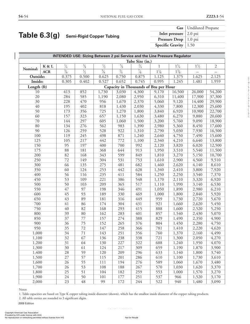
54-54 NATIONAL FUEL GAS CODE Z223.1-54
Gas Undiluted PropaneInlet pressure 2.0 psi
Pressure Drop 1.0 psiSpecific Gravity 1.50
INTENDED USE: Sizing Between 2 psi Service and the Line Pressure RegulatorTube Size (in.)
Nominal:K & L 1⁄4 3⁄8 1⁄2 5⁄8 3⁄4 1 11⁄4 11⁄2 2ACR 3⁄8 1⁄2 5⁄8 3⁄4 7⁄8 11⁄8 13⁄8 – –
Outside: 0.375 0.500 0.625 0.750 0.875 1.125 1.375 1.625 2.125Inside: 0.305 0.402 0.527 0.652 0.745 0.995 1.245 1.481 1.959
Length (ft) Capacity in Thousands of Btu per Hour10 413 852 1,730 3,030 4,300 9,170 16,500 26,000 54,20020 284 585 1,190 2,080 2,950 6,310 11,400 17,900 37,30030 228 470 956 1,670 2,370 5,060 9,120 14,400 29,90040 195 402 818 1,430 2,030 4,330 7,800 12,300 25,60050 173 356 725 1,270 1,800 3,840 6,920 10,900 22,70060 157 323 657 1,150 1,630 3,480 6,270 9,880 20,60070 144 297 605 1,060 1,500 3,200 5,760 9,090 18,90080 134 276 562 983 1,390 2,980 5,360 8,450 17,60090 126 259 528 922 1,310 2,790 5,030 7,930 16,500100 119 245 498 871 1,240 2,640 4,750 7,490 15,600125 105 217 442 772 1,100 2,340 4,210 6,640 13,800150 95 197 400 700 992 2,120 3,820 6,020 12,500175 88 181 368 644 913 1,950 3,510 5,540 11,500200 82 168 343 599 849 1,810 3,270 5,150 10,700250 72 149 304 531 753 1,610 2,900 4,560 9,510300 66 135 275 481 682 1,460 2,620 4,140 8,610350 60 124 253 442 628 1,340 2,410 3,800 7,920400 56 116 235 411 584 1,250 2,250 3,540 7,370450 53 109 221 386 548 1,170 2,110 3,320 6,920500 50 103 209 365 517 1,110 1,990 3,140 6,530550 47 97 198 346 491 1,050 1,890 2,980 6,210600 45 93 189 330 469 1,000 1,800 2,840 5,920650 43 89 181 316 449 959 1,730 2,720 5,670700 41 86 174 304 431 921 1,660 2,620 5,450750 40 82 168 293 415 888 1,600 2,520 5,250800 39 80 162 283 401 857 1,540 2,430 5,070850 37 77 157 274 388 829 1,490 2,350 4,900900 36 75 152 265 376 804 1,450 2,280 4,750950 35 72 147 258 366 781 1,410 2,220 4,620
1,000 34 71 143 251 356 760 1,370 2,160 4,4901,100 32 67 136 238 338 721 1,300 2,050 4,2701,200 31 64 130 227 322 688 1,240 1,950 4,0701,300 30 61 124 217 309 659 1,190 1,870 3,9001,400 28 59 120 209 296 633 1,140 1,800 3,7401,500 27 57 115 201 286 610 1,100 1,730 3,6101,600 26 55 111 194 276 589 1,060 1,670 3,4801,700 26 53 108 188 267 570 1,030 1,620 3,3701,800 25 51 104 182 259 553 1,000 1,570 3,2701,900 24 50 101 177 251 537 966 1,520 3,1702,000 23 48 99 172 244 522 940 1,480 3,090
Notes:1. Table capacities are based on Type K copper tubing inside diameter (shown), which has the smallest inside diameter of the copper tubing products.2. All table entries are rounded to 3 significant digits.
Table 6.3(g) Semi-Rigid Copper Tubing
2009 Edition
Copyright American Gas Association Provided by IHS under license with AGA
Not for ResaleNo reproduction or networking permitted without license from IHS
--`,,```,,,,````-`-`,,`,,`,`,,`---
//^:^
^#^~
^^""
~:@
":^*^
~$~"
#:*~
::*^~
:^^#
~~#^
~:^:
@:~
*:$"
\\

Z223.1-55 PIPE SIZING 54-55
2009 Edition
Gas Undiluted PropaneInlet pressure 11.0 in. w.c.
Pressure Drop 0.5 in. w.c.Specific Gravity 1.50
INTENDED USE: Sizing Between Single or Second Stage (Low Pressure) Regulatorand the Appliance Shutoff Valve
Tube Size (EHD)Designation: 13 15 18 19 23 25 30 31 37 39 46 48 60 62
Length (ft) Capacity in Thousands of Btu per Hour
5 72 99 181 211 355 426 744 863 1,420 1,638 2,830 3,270 5,780 6,550
10 50 69 129 150 254 303 521 605 971 1,179 1,990 2,320 4,110 4,640
15 39 55 104 121 208 248 422 490 775 972 1,620 1,900 3,370 3,790
20 34 49 91 106 183 216 365 425 661 847 1,400 1,650 2,930 3,290
25 30 42 82 94 164 192 325 379 583 762 1,250 1,480 2,630 2,940
30 28 39 74 87 151 177 297 344 528 698 1,140 1,350 2,400 2,680
40 23 33 64 74 131 153 256 297 449 610 988 1,170 2,090 2,330
50 20 30 58 66 118 137 227 265 397 548 884 1,050 1,870 2,080
60 19 26 53 60 107 126 207 241 359 502 805 961 1,710 1,900
70 17 25 49 57 99 117 191 222 330 466 745 890 1,590 1,760
80 15 23 45 52 94 109 178 208 307 438 696 833 1,490 1,650
90 15 22 44 50 90 102 169 197 286 414 656 787 1,400 1,550
100 14 20 41 47 85 98 159 186 270 393 621 746 1,330 1,480
150 11 15 31 36 66 75 123 143 217 324 506 611 1,090 1,210
200 9 14 28 33 60 69 112 129 183 283 438 531 948 1,050
250 8 12 25 30 53 61 99 117 163 254 390 476 850 934
300 8 11 23 26 50 57 90 107 147 234 357 434 777 854
Notes:1. Table includes losses for four 90-degree bends and two end fittings. Tubing runs with larger numbers of bends and/or fittings shall be increased by an equiva-lent length of tubing to the following equation: L = 1.3n where L is additional length (ft) of tubing and n is the number of additional fittings and/or bends.2. EHD — Equivalent Hydraulic Diameter, which is a measure of the relative hydraulic efficiency between different tubing sizes. The greater the value of EHD,the greater the gas capacity of the tubing.3. All table entries are rounded to 3 significant digits.
Table 6.3(h) Corrugated Stainless Steel Tubing(CSST)
Copyright American Gas Association Provided by IHS under license with AGA
Not for ResaleNo reproduction or networking permitted without license from IHS
--`,,```,,,,````-`-`,,`,,`,`,,`---
//^:^^#^~^^""~:@":^*^~$~"#:*~::*^~:^^#~~#^~:^:@:~*:$"\\

54-56 NATIONAL FUEL GAS CODE Z223.1-56
Gas Undiluted PropaneInlet pressure 2.0 psi
Pressure Drop 1.0 psiSpecific Gravity 1.50
INTENDED USE: Sizing Between 2 psi Service and the Line Pressure RegulatorFlow Tube Size (EHD)
Designation: 13 15 18 19 23 25 30 31 37 39 46 48 60 62
Length (ft) Capacity in Thousands of Btu per Hour
10 426 558 927 1,110 1,740 2,170 4,100 4,720 7,130 7,958 15,200 16,800 29,400 34,200
25 262 347 591 701 1,120 1,380 2,560 2,950 4,560 5,147 9,550 10,700 18,800 21,700
30 238 316 540 640 1,030 1,270 2,330 2,690 4,180 4,719 8,710 9,790 17,200 19,800
40 203 271 469 554 896 1,100 2,010 2,320 3,630 4,116 7,530 8,500 14,900 17,200
50 181 243 420 496 806 986 1,790 2,070 3,260 3,702 6,730 7,610 13,400 15,400
75 147 196 344 406 663 809 1,460 1,690 2,680 3,053 5,480 6,230 11,000 12,600
80 140 189 333 393 643 768 1,410 1,630 2,590 2,961 5,300 6,040 10,600 12,200
100 124 169 298 350 578 703 1,260 1,450 2,330 2,662 4,740 5,410 9,530 10,900
150 101 137 245 287 477 575 1,020 1,180 1,910 2,195 3,860 4,430 7,810 8,890
200 86 118 213 248 415 501 880 1,020 1,660 1,915 3,340 3,840 6,780 7,710
250 77 105 191 222 373 448 785 910 1,490 1,722 2,980 3,440 6,080 6,900
300 69 96 173 203 343 411 716 829 1,360 1,578 2,720 3,150 5,560 6,300
400 60 82 151 175 298 355 616 716 1,160 1,376 2,350 2,730 4,830 5,460
500 53 72 135 158 268 319 550 638 1,030 1,237 2,100 2,450 4,330 4,880
Notes:1. Table does not include effect of pressure drop across the line regulator. Where regulator loss exceeds 1⁄2 psi (based on 13 in. w.c. outlet pressure), DO NOTUSE THIS TABLE. Consult with regulator manufacturer for pressure drops and capacity factors. Pressure drops across a regulator may vary with flow rate.2. CAUTION: Capacities shown in table may exceed maximum capacity for a selected regulator. Consult with regulator or tubing manufacturer for guidance.3. Table includes losses for four 90-degree bends and two end fittings. Tubing runs with larger numbers of bends and/or fittings shall be increased by an equiva-lent length of tubing to the following equation: L = 1.3n where L is additional length (ft) of tubing and n is the number of additional fittings and/or bends.4. EHD — Equivalent Hydraulic Diameter, which is a measure of the relative hydraulic efficiency between different tubing sizes. The greater the value of EHD,the greater the gas capacity of the tubing.5. All table entries are rounded to 3 significant digits.
Table 6.3(i) Corrugated Stainless Steel Tubing(CSST)
2009 Edition
Copyright American Gas Association Provided by IHS under license with AGA
Not for ResaleNo reproduction or networking permitted without license from IHS
--`,,```,,,,````-`-`,,`,,`,`,,`---
//^:^^#^~^^""~:@":^*^~$~"#:*~::*^~:^^#~~#^~:^:@
:~*:$"\\

Z223.1-57 PIPE SIZING 54-57
2009 Edition
Gas Undiluted PropaneInlet pressure 5.0 psi
Pressure Drop 3.5 psiSpecific Gravity 1.50
Tube Size (EHD)Flow: 13 15 18 19 23 25 30 31 37 39 46 48 60 62
Length (ft) Capacity in Thousands of Btu per Hour
10 826 1,070 1,710 2,060 3,150 4,000 7,830 8,950 13,100 14,444 28,600 31,200 54,400 63,800
25 509 664 1,090 1,310 2,040 2,550 4,860 5,600 8,400 9,339 18,000 19,900 34,700 40,400
30 461 603 999 1,190 1,870 2,340 4,430 5,100 7,680 8,564 16,400 18,200 31,700 36,900
40 396 520 867 1,030 1,630 2,030 3,820 4,400 6,680 7,469 14,200 15,800 27,600 32,000
50 352 463 777 926 1,460 1,820 3,410 3,930 5,990 6,717 12,700 14,100 24,700 28,600
75 284 376 637 757 1,210 1,490 2,770 3,190 4,920 5,539 10,300 11,600 20,300 23,400
80 275 363 618 731 1,170 1,450 2,680 3,090 4,770 5,372 9,990 11,200 19,600 22,700
100 243 324 553 656 1,050 1,300 2,390 2,760 4,280 4,830 8,930 10,000 17,600 20,300
150 196 262 453 535 866 1,060 1,940 2,240 3,510 3,983 7,270 8,210 14,400 16,600
200 169 226 393 464 755 923 1,680 1,930 3,050 3,474 6,290 7,130 12,500 14,400
250 150 202 352 415 679 828 1,490 1,730 2,740 3,124 5,620 6,390 11,200 12,900
300 136 183 322 379 622 757 1,360 1,570 2,510 2,865 5,120 5,840 10,300 11,700
400 117 158 279 328 542 657 1,170 1,360 2,180 2,498 4,430 5,070 8,920 10,200
500 104 140 251 294 488 589 1,050 1,210 1,950 2,247 3,960 4,540 8,000 9,110
Notes:1. Table does not include effect of pressure drop across line regulator. Where regulator loss exceeds1 psi, DO NOT USE THIS TABLE. Consult with regulatormanufacturer for pressure drops and capacity factors. Pressure drop across regulator may vary with the flow rate.2. CAUTION: Capacities shown in table may exceed maximum capacity of selected regulator. Consult with tubing manufacturer for guidance.3. Table includes losses for four 90-degree bends and two end fittings. Tubing runs with larger numbers of bends and/or fittings shall be increased by an equiva-lent length of tubing to the following equation: L = 1.3n where L is additional length (ft) of tubing and n is the number of additional fittings and/or bends.4. EHD — Equivalent Hydraulic Diameter, which is a measure of the relative hydraulic efficiency between different tubing sizes. The greater the value of EHD,the greater the gas capacity of the tubing.5. All table entries are rounded to 3 significant digits.
Table 6.3(j) Corrugated Stainless Steel Tubing(CSST)
Copyright American Gas Association Provided by IHS under license with AGA
Not for ResaleNo reproduction or networking permitted without license from IHS
--`,,```,,,,````-`-`,,`,,`,`,,`---
//^:^
^#^~
^^""
~:@
":^*^
~$~"
#:*~
::*^~
:^^#
~~#^
~:^:
@:~
*:$"
\\

54-58 NATIONAL FUEL GAS CODE Z223.1-58
INTENDED USE: Sizing Between Integral 2-Stage Regulator at Tankor Second Stage (Low Pressure Regulator) and the Building
Pipe Size (in.)Nominal OD: 1⁄2 3⁄4 1 1 1⁄4 1 1⁄2 2Designation: SDR 9.33 SDR 11.0 SDR 11.00 SDR 10.00 SDR 11.00 SDR 11.00Actual ID: 0.660 0.860 1.077 1.328 1.554 1.943
Length (ft) Capacity in Thousands of Btu per Hour
10 340 680 1,230 2,130 3,210 5,770
20 233 468 844 1,460 2,210 3,970
30 187 375 677 1,170 1,770 3,180
40 160 321 580 1,000 1,520 2,730
50 142 285 514 890 1,340 2,420
60 129 258 466 807 1,220 2,190
70 119 237 428 742 1,120 2,010
80 110 221 398 690 1,040 1,870
90 103 207 374 648 978 1,760
100 98 196 353 612 924 1,660
125 87 173 313 542 819 1,470
150 78 157 284 491 742 1,330
175 72 145 261 452 683 1,230
200 67 135 243 420 635 1,140
250 60 119 215 373 563 1,010
300 54 108 195 338 510 916
350 50 99 179 311 469 843
400 46 92 167 289 436 784
450 43 87 157 271 409 736
500 41 82 148 256 387 695
Note: All table entries are rounded to 3 significant digits.
Table 6.3(k) Polyethylene Plastic Pipe
Gas Undiluted PropaneInlet pressure 11.0 in. w.c.
Pressure Drop 0.5 in. w.c.Specific Gravity 1.50
2009 Edition
Copyright American Gas Association Provided by IHS under license with AGA
Not for ResaleNo reproduction or networking permitted without license from IHS
--`,,```,,,,````-`-`,,`,,`,`,,`---
//^:^^#^~^^""~:@":^*^~$~"#:*~::*^~:^^#~~#^~:^:@
:~*:$"\\

Z223.1-59 PIPE SIZING 54-59
2009 Edition
INTENDED USE: Sizing Between 2 psi Service and the Line Pressure RegulatorPipe Size (in.)
Nominal OD: 1⁄2 3⁄4 1 1 1⁄4 1 1⁄2 2Designation: SDR 9.33 SDR 11.0 SDR 11.00 SDR 10.00 SDR 11.00 SDR 11.00Actual ID: 0.660 0.860 1.077 1.328 1.554 1.943Length (ft) Capacity in Thousands of Btu per Hour
10 3,130 6,260 11,300 19,600 29,500 53,10020 2,150 4,300 7,760 13,400 20,300 36,50030 1,730 3,450 6,230 10,800 16,300 29,30040 1,480 2,960 5,330 9,240 14,000 25,10050 1,310 2,620 4,730 8,190 12,400 22,20060 1,190 2,370 4,280 7,420 11,200 20,10070 1,090 2,180 3,940 6,830 10,300 18,50080 1,010 2,030 3,670 6,350 9,590 17,20090 952 1,910 3,440 5,960 9,000 16,200
100 899 1,800 3,250 5,630 8,500 15,300125 797 1,600 2,880 4,990 7,530 13,500150 722 1,450 2,610 4,520 6,830 12,300175 664 1,330 2,400 4,160 6,280 11,300200 618 1,240 2,230 3,870 5,840 10,500250 548 1,100 1,980 3,430 5,180 9,300300 496 994 1,790 3,110 4,690 8,430350 457 914 1,650 2,860 4,320 7,760400 425 851 1,530 2,660 4,020 7,220450 399 798 1,440 2,500 3,770 6,770500 377 754 1,360 2,360 3,560 6,390550 358 716 1,290 2,240 3,380 6,070600 341 683 1,230 2,140 3,220 5,790650 327 654 1,180 2,040 3,090 5,550700 314 628 1,130 1,960 2,970 5,330750 302 605 1,090 1,890 2,860 5,140800 292 585 1,050 1,830 2,760 4,960850 283 566 1,020 1,770 2,670 4,800900 274 549 990 1,710 2,590 4,650950 266 533 961 1,670 2,520 4,520
1,000 259 518 935 1,620 2,450 4,4001,100 246 492 888 1,540 2,320 4,1701,200 234 470 847 1,470 2,220 3,9801,300 225 450 811 1,410 2,120 3,8101,400 216 432 779 1,350 2,040 3,6601,500 208 416 751 1,300 1,960 3,5301,600 201 402 725 1,260 1,900 3,4101,700 194 389 702 1,220 1,840 3,3001,800 188 377 680 1,180 1,780 3,2001,900 183 366 661 1,140 1,730 3,1102,000 178 356 643 1,110 1,680 3,020
Note: All table entries are rounded to 3 significant digits.
Table 6.3(l) Polyethylene Plastic Pipe
Gas Undiluted PropaneInlet pressure 2.0 psi
Pressure Drop 1.0 psiSpecific Gravity 1.50
Copyright American Gas Association Provided by IHS under license with AGA
Not for ResaleNo reproduction or networking permitted without license from IHS
--`,,```,,,,````-`-`,,`,,`,`,,`---
//^:^^#^~^^""~:@":^*^~$~"#:*~::*^~:^^#~~#^~:^:@:~*:$"\\

54-60 NATIONAL FUEL GAS CODE Z223.1-60
2009 Edition
Table 6.3(m)Polyethylene Plastic Tubing
Gas Undiluted Propane
Inlet pressure 11.0 in. w.c.
Pressure Drop 0.5 in. w.c.
Specific Gravity 1.50
Sizing Between Integral 2-StageRegulator at Tank or Second Stage(Low Pressure Regulator)and the Building
Plastic Tubing Size (CTS) (in.)
Nominal OD: 1⁄2 1
Designation: SDR 7.00 SDR 11.00
Actual ID: 0.445 0.927
Length Capacity in(ft) Thousands of Btu per Hour
10 121 828
20 83 569
30 67 457
40 57 391
50 51 347
60 46 314
70 42 289
80 39 269
90 37 252
100 35 238
125 31 211
150 28 191
175 26 176
200 24 164
225 22 154
250 21 145
275 20 138
300 19 132
350 18 121
400 16 113
450 15 106
500 15 100
Note: All table entries are rounded to 3 significant digits.
Chapter 7 Gas Piping Installation
7.1 Piping Underground.
7.1.1 Clearances. Underground gas piping shall beinstalled with sufficient clearance from any other under-ground structure to avoid contact therewith, to allow main-tenance, and to protect against damage from proximity toother structures. In addition, underground plastic pipingshall be installed with sufficient clearance or shall be insu-lated from any source of heat so as to prevent the heat fromimpairing the serviceability of the pipe.
7.1.2 Protection Against Damage. Means shall be provid-ed to prevent excessive stressing of the piping where there isheavy vehicular traffic or soil conditions are unstable andsettling of piping or foundation walls could occur. Pipingshall be buried or covered in a manner so as to protect thepiping from physical damage. Piping shall be protectedfrom physical damage where it passes through flower beds,shrub beds, and other such cultivated areas where suchdamage is reasonably expected.
7.1.2.1 Cover Requirements. Underground piping sys-tems shall be installed with a minimum of 12 in. (300mm) of cover.(A) The minimum cover shall be increased to 18 in.
(460 mm) if external damage to the pipe or tubingfrom external forces is likely to result.
(B) Where a minimum of 12 in. (300 mm) of covercannot be provided, the pipe shall be installed inconduit or bridged (shielded).
7.1.2.2 Trenches. The trench shall be graded so that thepipe has a firm, substantially continuous bearing on thebottom of the trench.
7.1.2.3 Backfilling. Where flooding of the trench isdone to consolidate the backfill, care shall be exercised tosee that the pipe is not floated from its firm bearing onthe trench bottom.
7.1.3* Protection Against Corrosion. Gas piping in con-tact with earth or other material that could corrode the pip-ing shall be protected against corrosion in an approvedmanner. When dissimilar metals are joined underground,an insulating coupling or fitting shall be used. Piping shallnot be laid in contact with cinders. Uncoated threaded orsocket welded joints shall not be used in piping in contactwith soil or where internal or external crevice corrosion isknown to occur.
7.1.4* Protection Against Freezing. Where the formationof hydrates or ice is known to occur, piping shall be pro-
INTENDED USE
Copyright American Gas Association Provided by IHS under license with AGA
Not for ResaleNo reproduction or networking permitted without license from IHS
--`,,```,,,,````-`-`,,`,,`,`,,`---
//^:^^#^~^^""~:@":^*^~$~"#:*~::*^~:^^#~~#^~:^:@:~*:$"\\
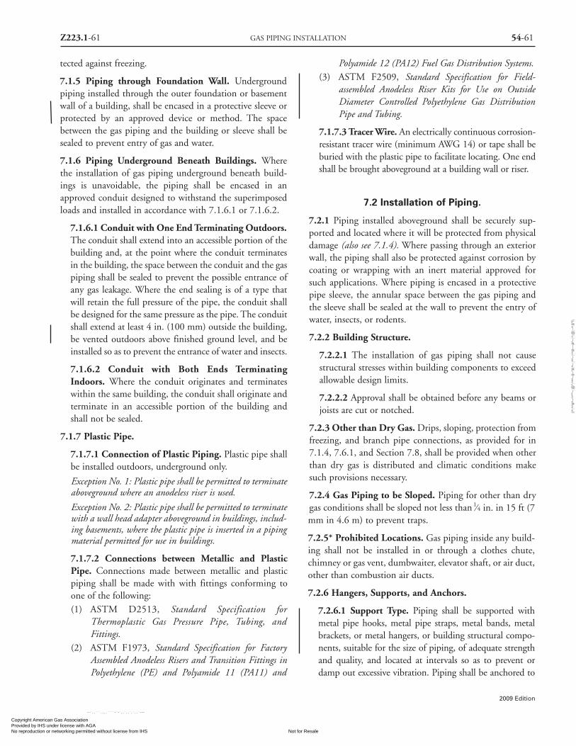
Z223.1-61 GAS PIPING INSTALLATION 54-61
2009 Edition
tected against freezing.
7.1.5 Piping through Foundation Wall. Undergroundpiping installed through the outer foundation or basementwall of a building, shall be encased in a protective sleeve orprotected by an approved device or method. The spacebetween the gas piping and the building or sleeve shall besealed to prevent entry of gas and water.
7.1.6 Piping Underground Beneath Buildings. Wherethe installation of gas piping underground beneath build-ings is unavoidable, the piping shall be encased in anapproved conduit designed to withstand the superimposedloads and installed in accordance with 7.1.6.1 or 7.1.6.2.
7.1.6.1 Conduit with One End Terminating Outdoors.The conduit shall extend into an accessible portion of thebuilding and, at the point where the conduit terminatesin the building, the space between the conduit and the gaspiping shall be sealed to prevent the possible entrance ofany gas leakage. Where the end sealing is of a type thatwill retain the full pressure of the pipe, the conduit shallbe designed for the same pressure as the pipe. The conduitshall extend at least 4 in. (100 mm) outside the building,be vented outdoors above finished ground level, and beinstalled so as to prevent the entrance of water and insects.
7.1.6.2 Conduit with Both Ends TerminatingIndoors. Where the conduit originates and terminateswithin the same building, the conduit shall originate andterminate in an accessible portion of the building andshall not be sealed.
7.1.7 Plastic Pipe.
7.1.7.1 Connection of Plastic Piping. Plastic pipe shallbe installed outdoors, underground only.
Exception No. 1: Plastic pipe shall be permitted to terminateaboveground where an anodeless riser is used.
Exception No. 2: Plastic pipe shall be permitted to terminatewith a wall head adapter aboveground in buildings, includ-ing basements, where the plastic pipe is inserted in a pipingmaterial permitted for use in buildings.
7.1.7.2 Connections between Metallic and PlasticPipe. Connections made between metallic and plasticpiping shall be made with with fittings conforming toone of the following:(1) ASTM D2513, Standard Specification for
Thermoplastic Gas Pressure Pipe, Tubing, andFittings.
(2) ASTM F1973, Standard Specification for FactoryAssembled Anodeless Risers and Transition Fittings inPolyethylene (PE) and Polyamide 11 (PA11) and
Polyamide 12 (PA12) Fuel Gas Distribution Systems.(3) ASTM F2509, Standard Specification for Field-
assembled Anodeless Riser Kits for Use on OutsideDiameter Controlled Polyethylene Gas DistributionPipe and Tubing.
7.1.7.3 Tracer Wire. An electrically continuous corrosion-resistant tracer wire (minimum AWG 14) or tape shall beburied with the plastic pipe to facilitate locating. One endshall be brought aboveground at a building wall or riser.
7.2 Installation of Piping.
7.2.1 Piping installed aboveground shall be securely sup-ported and located where it will be protected from physicaldamage (also see 7.1.4). Where passing through an exteriorwall, the piping shall also be protected against corrosion bycoating or wrapping with an inert material approved forsuch applications. Where piping is encased in a protectivepipe sleeve, the annular space between the gas piping andthe sleeve shall be sealed at the wall to prevent the entry ofwater, insects, or rodents.
7.2.2 Building Structure.
7.2.2.1 The installation of gas piping shall not causestructural stresses within building components to exceedallowable design limits.
7.2.2.2 Approval shall be obtained before any beams orjoists are cut or notched.
7.2.3 Other than Dry Gas. Drips, sloping, protection fromfreezing, and branch pipe connections, as provided for in7.1.4, 7.6.1, and Section 7.8, shall be provided when otherthan dry gas is distributed and climatic conditions makesuch provisions necessary.
7.2.4 Gas Piping to be Sloped. Piping for other than drygas conditions shall be sloped not less than 1⁄4 in. in 15 ft (7mm in 4.6 m) to prevent traps.
7.2.5* Prohibited Locations. Gas piping inside any build-ing shall not be installed in or through a clothes chute,chimney or gas vent, dumbwaiter, elevator shaft, or air duct,other than combustion air ducts.
7.2.6 Hangers, Supports, and Anchors.
7.2.6.1 Support Type. Piping shall be supported withmetal pipe hooks, metal pipe straps, metal bands, metalbrackets, or metal hangers, or building structural compo-nents, suitable for the size of piping, of adequate strengthand quality, and located at intervals so as to prevent ordamp out excessive vibration. Piping shall be anchored to
Copyright American Gas Association Provided by IHS under license with AGA
Not for ResaleNo reproduction or networking permitted without license from IHS
--`,,```,,,,````-`-`,,`,,`,`,,`---
//^:^
^#^~
^^""
~:@
":^*^
~$~"
#:*~
::*^~
:^^#
~~#^
~:^:
@:~
*:$"
\\

54-62 NATIONAL FUEL GAS CODE Z223.1-62
prevent undue strains on connected appliances and equip-ment and shall not be supported by other piping. Pipehangers and supports shall conform to the requirements ofANSI/MSS SP-58, Pipe Hangers and Supports —Materials, Design and Manufacture.
7.2.6.2 Support Spacing. Spacings of supports in gaspiping installations shall not be greater than shown inTable 7.2.6.2. Spacing of supports for CSST shall be inaccordance with the CSST manufacturer’s instructions.
Table 7.2.6.2 Support of Piping
Steel Pipe, Nominal SizeNominal Spacing of of Tubing Spacing of
Size of Pipe Supports Smooth-wall Supports(in.) (ft) (Inch O.D.) (ft)
1⁄2 6 1⁄2 43⁄4 or 1 8 5⁄8 or 3⁄4 6
1 1⁄4 or larger 107⁄8 or 1 8
(horizontal) (horizontal)1 1⁄4 or larger every floor 1 or larger every floor
(vertical) level (vertical) level
For SI units: 1 ft = 0.305 m.
7.2.6.3 Freedom of Movement. Supports, hangers, andanchors shall be installed so as not to interfere with thefree expansion and contraction of the piping betweenanchors. All parts of the supporting system shall bedesigned and installed so they will not be disengaged bymovement of the supported piping.
7.2.6.4 Piping on Roof Tops. Gas piping installed onthe roof surfaces shall be elevated above the roof surfaceand shall be supported in accordance with Table 7.2.6.2.
7.2.7 Removal of Pipe. Where piping containing gas is to beremoved, the line shall be first disconnected from all sourcesof gas and then thoroughly purged with air, water, or inert gasbefore any cutting or welding is done. [See Section 8.3.]
7.2.8 CSST. CSST piping systems shall be installed inaccordance with this code and the manufacturer’s installa-tion instructions.
7.3 Concealed Piping in Buildings.
7.3.1 General. Gas piping in concealed locations shall beinstalled in accordance with this section.
7.3.2 Connections. Where gas piping is to be concealed,unions, tubing fittings, right and left couplings, bushings,swing joints, and compression couplings made by combina-
tions of fittings shall not be used. Connections shall be ofthe following type:
(1) Pipe fittings such as elbows, tees, and couplings
(2) Joining tubing by brazing [see 5.6.8.2](3) Fittings listed for use in concealed spaces that have
been demonstrated to sustain, without leakage, anyforces due to temperature expansion or contraction,vibration, or fatigue based on their geographic loca-tion, application, or operation.
(4) Where necessary to insert fittings in gas pipe that hasbeen installed in a concealed location, the pipe shall bereconnected by welding, flanges, or the use of a groundjoint union with the nut center-punched to preventloosening by vibration.
7.3.3 Piping in Partitions. Concealed gas piping shall notbe located in solid partitions.
7.3.4 Tubing in Partitions. This provision shall not applyto tubing that pierces walls, floors, or partitions. Tubinginstalled vertically and horizontally inside hollow walls orpartitions without protection along its entire concealedlength shall meet the following requirements:
(1) A steel striker barrier not less than 0.0508 in. (1.3 mm)thick, or equivalent, is installed between the tubingand the finished wall and extends at least 4 in. (100mm) beyond concealed penetrations of plates, firestops, wall studs, and so on.
(2) The tubing is installed in single runs and is not rigidlysecured.
7.3.5 Piping in Floors.
7.3.5.1 Industrial Occupancies. In industrial occupan-cies, gas piping in solid floors such as concrete shall belaid in channels in the floor and covered to permit accessto the piping with a minimum of damage to the build-ing. Where piping in floor channels could be exposed toexcessive moisture or corrosive substances, the pipingshall be protected in an approved manner.
7.3.5.2 Other Occupancies. In other than industrialoccupancies and where approved by the authority havingjurisdiction, gas piping embedded in concrete floor slabsconstructed with portland cement shall be surroundedwith a minimum of 11⁄2 in. (38 mm) of concrete and shallnot be in physical contact with other metallic structuressuch as reinforcing rods or electrically neutral conduc-tors. All piping, fittings, and risers shall be protectedagainst corrosion in accordance with 5.6.6. Piping shallnot be embedded in concrete slabs containing quicksetadditives or cinder aggregate.
2009 Edition
Copyright American Gas Association Provided by IHS under license with AGA
Not for ResaleNo reproduction or networking permitted without license from IHS
--`,,```,,,,````-`-`,,`,,`,`,,`---
//^:^^#^~^^""~:@":^*^~$~"#:*~::*^~:^^#~~#^~:^:@:~*:$"\\

Z223.1-63 GAS PIPING INSTALLATION 54-63
2009 Edition
7.4 Piping in Vertical Chases.
Where gas piping exceeding 5 psi (34 kPa) is located with-in vertical chases in accordance with 5.5.1 (2), the require-ments of 7.4.1 through 7.4.3 shall apply.
7.4.1 Pressure Reduction. Where pressure reduction isrequired in branch connections for compliance with 5.5.1,such reduction shall take place either inside the chase orimmediately adjacent to the outside wall of the chase.Regulator venting and downstream overpressure protectionshall comply with 5.8.5 and Section 5.9. The regulator shallbe accessible for service and repair and vented in accordancewith one of the following:(1) Where the fuel gas is lighter than air, regulators
equipped with a vent-limiting means shall be permit-ted to be vented into the chase. Regulators notequipped with a vent-limiting means shall be permit-ted to be vented either directly to the outdoors or to apoint within the top 1 ft (0.3m) of the chase.
(2) Where the fuel gas is heavier than air, the regulatorvent shall be vented only directly to the outdoors.
7.4.2 Chase Construction. Chase construction shall com-ply with local building codes with respect to fire resistanceand protection of horizontal and vertical openings.
7.4.3* Ventilation. A chase shall be ventilated to the out-doors and only at the top. The opening(s) shall have a mini-mum free area (in square inches) equal to the product of one-half of the maximum pressure in the piping (in psi) times thelargest nominal diameter of that piping (in inches), or thecross-sectional area of the chase, whichever is smaller. Wheremore than one fuel gas piping system is present, the free areafor each system shall be calculated and the largest area used.
7.5 Gas Pipe Turns.
Changes in direction of gas pipe shall be made by the use offittings, factory bends, or field bends.
7.5.1 Metallic Pipe. Metallic pipe bends shall comply withthe following:(1) Bends shall be made only with bending tools and pro-
cedures intended for that purpose.(2) All bends shall be smooth and free from buckling,
cracks, or other evidence of mechanical damage.(3) The longitudinal weld of the pipe shall be near the
neutral axis of the bend.(4) Pipe shall not be bent through an arc of more than 90
degrees.(5) The inside radius of a bend shall be not less than 6
times the outside diameter of the pipe.
7.5.2 Plastic Pipe. Plastic pipe bends shall comply with thefollowing:
(1) The pipe shall not damaged, and the internal diameterof the pipe shall not be effectively reduced.
(2) Joints shall not be located in pipe bends.
(3) The radius of the inner curve of such bends shall notbe less than 25 times the inside diameter of the pipe.
(4) Where the piping manufacturer specifies the use ofspecial bending tools or procedures, such tools or pro-cedures shall be used.
7.5.3 Elbows. Factory-made welding elbows or transversesegments cut therefrom shall have an arc length measuredalong the crotch of at least 1 in. (25 mm) in pipe sizes 2 in.and larger.
7.6 Drips and Sediment Traps.
7.6.1 Provide Drips Where Necessary. For other than drygas conditions, a drip shall be provided at any point in theline of pipe where condensate could collect. Where requiredby the authority having jurisdiction or the serving gas sup-plier, a drip shall also be provided at the outlet of the meter.This drip shall be so installed as to constitute a trap where-in an accumulation of condensate will shut off the flow ofgas before it will run back into the meter.
7.6.2 Location of Drips. All drips shall be installed only insuch locations that they will be readily accessible to permitcleaning or emptying. A drip shall not be located where thecondensate is likely to freeze.
7.6.3 Sediment Traps. [See 9.6.7.]
7.7 Outlets.
7.7.1 Location and Installation.
7.7.1.1 The outlet fittings or piping shall be securelyfastened in place.
7.7.1.2 Outlets shall not be located behind doors.
7.7.1.3 Outlets shall be located far enough from floors,walls, patios, slabs, and ceilings to permit the use of wrench-es without straining, bending, or damaging the piping.
7.7.1.4 The unthreaded portion of gas piping outletsshall extend not less than 1 in. (25 mm) through finishedceilings or indoor or outdoor walls.
7.7.1.5 The unthreaded portion of gas piping outlets
Copyright American Gas Association Provided by IHS under license with AGA
Not for ResaleNo reproduction or networking permitted without license from IHS
--`,,```,,,,````-`-`,,`,,`,`,,`---
//^:^
^#^~
^^""
~:@
":^*^
~$~"
#:*~
::*^~
:^^#
~~#^
~:^:
@:~
*:$"
\\
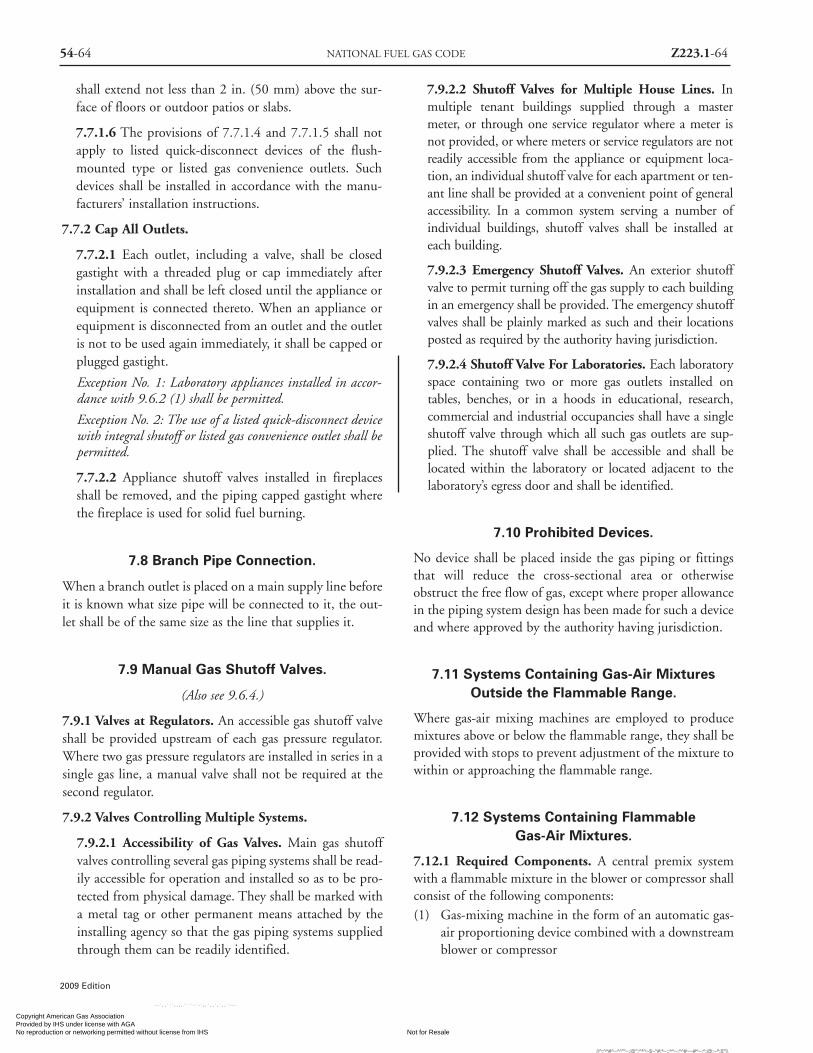
54-64 NATIONAL FUEL GAS CODE Z223.1-64
2009 Edition
shall extend not less than 2 in. (50 mm) above the sur-face of floors or outdoor patios or slabs.
7.7.1.6 The provisions of 7.7.1.4 and 7.7.1.5 shall notapply to listed quick-disconnect devices of the flush-mounted type or listed gas convenience outlets. Suchdevices shall be installed in accordance with the manu-facturers’ installation instructions.
7.7.2 Cap All Outlets.
7.7.2.1 Each outlet, including a valve, shall be closedgastight with a threaded plug or cap immediately afterinstallation and shall be left closed until the appliance orequipment is connected thereto. When an appliance orequipment is disconnected from an outlet and the outletis not to be used again immediately, it shall be capped orplugged gastight.
Exception No. 1: Laboratory appliances installed in accor-dance with 9.6.2 (1) shall be permitted.
Exception No. 2: The use of a listed quick-disconnect devicewith integral shutoff or listed gas convenience outlet shall bepermitted.
7.7.2.2 Appliance shutoff valves installed in fireplacesshall be removed, and the piping capped gastight wherethe fireplace is used for solid fuel burning.
7.8 Branch Pipe Connection.
When a branch outlet is placed on a main supply line beforeit is known what size pipe will be connected to it, the out-let shall be of the same size as the line that supplies it.
7.9 Manual Gas Shutoff Valves.
(Also see 9.6.4.)
7.9.1 Valves at Regulators. An accessible gas shutoff valveshall be provided upstream of each gas pressure regulator.Where two gas pressure regulators are installed in series in asingle gas line, a manual valve shall not be required at thesecond regulator.
7.9.2 Valves Controlling Multiple Systems.
7.9.2.1 Accessibility of Gas Valves. Main gas shutoffvalves controlling several gas piping systems shall be read-ily accessible for operation and installed so as to be pro-tected from physical damage. They shall be marked witha metal tag or other permanent means attached by theinstalling agency so that the gas piping systems suppliedthrough them can be readily identified.
7.9.2.2 Shutoff Valves for Multiple House Lines. Inmultiple tenant buildings supplied through a mastermeter, or through one service regulator where a meter isnot provided, or where meters or service regulators are notreadily accessible from the appliance or equipment loca-tion, an individual shutoff valve for each apartment or ten-ant line shall be provided at a convenient point of generalaccessibility. In a common system serving a number ofindividual buildings, shutoff valves shall be installed ateach building.
7.9.2.3 Emergency Shutoff Valves. An exterior shutoffvalve to permit turning off the gas supply to each buildingin an emergency shall be provided. The emergency shutoffvalves shall be plainly marked as such and their locationsposted as required by the authority having jurisdiction.
7.9.2.4 Shutoff Valve For Laboratories. Each laboratoryspace containing two or more gas outlets installed ontables, benches, or in a hoods in educational, research,commercial and industrial occupancies shall have a singleshutoff valve through which all such gas outlets are sup-plied. The shutoff valve shall be accessible and shall belocated within the laboratory or located adjacent to thelaboratory’s egress door and shall be identified.
7.10 Prohibited Devices.
No device shall be placed inside the gas piping or fittingsthat will reduce the cross-sectional area or otherwiseobstruct the free flow of gas, except where proper allowancein the piping system design has been made for such a deviceand where approved by the authority having jurisdiction.
7.11 Systems Containing Gas-Air MixturesOutside the Flammable Range.
Where gas-air mixing machines are employed to producemixtures above or below the flammable range, they shall beprovided with stops to prevent adjustment of the mixture towithin or approaching the flammable range.
7.12 Systems Containing FlammableGas-Air Mixtures.
7.12.1 Required Components. A central premix systemwith a flammable mixture in the blower or compressor shallconsist of the following components:(1) Gas-mixing machine in the form of an automatic gas-
air proportioning device combined with a downstreamblower or compressor
Copyright American Gas Association Provided by IHS under license with AGA
Not for ResaleNo reproduction or networking permitted without license from IHS
--`,,```,,,,````-`-`,,`,,`,`,,`---
//^:^^#^~^^""~:@":^*^~$~"#:*~::*^~:^^#~~#^~:^:@:~*:$"\\

Z223.1-65 GAS PIPING INSTALLATION 54-65
2009 Edition
(2) Flammable mixture piping, minimum Schedule 40 NPS
(3) Automatic firecheck(s)
(4) Safety blowout(s) or backfire preventers for systemsutilizing flammable mixture lines above 21⁄2 in. nominalpipe size or the equivalent
7.12.2 Optional Components. The following componentsshall also be permitted to be utilized in any type central pre-mix system:
(1) Flowmeter(s)
(2) Flame arrester(s)
7.12.3 Additional Requirements. Gas-mixing machinesshall have nonsparking blowers and shall be so constructedthat a flashback will not rupture machine casings.
7.12.4* Special Requirements for Mixing Blowers. A mix-ing blower system shall be limited to applications with mini-mum practical lengths of mixture piping, limited to a maxi-mum mixture pressure of 10 in. w.c. (2.5 kPa) and limited togases containing no more than 10 percent hydrogen. Theblower shall be equipped with a gas-control valve at its airentrance so arranged that gas is admitted to the airstream,entering the blower in proper proportions for correct com-bustion by the type of burners employed, the said gas-controlvalve being of either the zero governor or mechanical ratiovalve type that controls the gas and air adjustment simultane-ously. No valves or other obstructions shall be installedbetween the blower discharge and the burner or burners.
7.12.5 Installation of Gas-Mixing Machines.
7.12.5.1* Location. The gas-mixing machine shall belocated in a large, well-ventilated area or in a smalldetached building or cutoff room provided with roomconstruction and explosion vents in accordance withsound engineering principles. Such rooms or below fin-ished ground level installations shall have adequate posi-tive ventilation.
7.12.5.2 Electrical Requirements. Where gas-mixingmachines are installed in well-ventilated areas, the type ofelectrical equipment shall be in accordance with NFPA70®, National Electrical Code®, for general service condi-tions unless other hazards in the area prevail. Where gas-mixing machines are installed in small detached buildingsor cutoff rooms, the electrical equipment and wiring shallbe installed in accordance with NFPA 70® for hazardouslocations (Articles 500 and 501, Class I, Division 2).
7.12.5.3 Air Intakes. Air intakes for gas-mixingmachines using compressors or blowers shall be takenfrom outdoors whenever practical.
7.12.5.4* Controls. Controls for gas-mixing machinesshall include interlocks and a safety shutoff valve of themanual reset type in the gas supply connection to eachmachine arranged to automatically shut off the gas sup-ply in the event of high or low gas pressure. Except foropen burner installations only, the controls shall be inter-locked so that the blower or compressor will stop operat-ing following a gas supply failure. Where a systememploys pressurized air, means shall be provided to shutoff the gas supply in the event of air failure.
7.12.5.5 Installation in Parallel. Centrifugal gas-mixingmachines in parallel shall be reviewed by the user andequipment manufacturer before installation, and meansor plans for minimizing these effects of downstream pul-sation and equipment overload shall be prepared and uti-lized as needed.
7.12.6 Use of Automatic Firechecks, Safety Blowouts, orBackfire Preventers. Automatic firechecks and safetyblowouts or backfire preventers shall be provided in pipingsystems distributing flammable air-gas mixtures from gas-mixing machines to protect the piping and the machines inthe event of flashback, in accordance with the following:(1)* Approved automatic firechecks shall be installed
upstream as close as practicable to the burner inlets fol-lowing the firecheck manufacturers’ instructions.
(2) A separate manually operated gas valve shall be provid-ed at each automatic firecheck for shutting off the flowof gas-air mixture through the firecheck after a flash-back has occurred. The valve shall be located upstreamas close as practical to the inlet of the automaticfirecheck. Caution: these valves shall not be reopenedafter a flashback has occurred until the firecheck hascooled sufficiently to prevent reignition of the flam-mable mixture and has been reset properly.
(3) A safety blowout or backfiring preventer shall be pro-vided in the mixture line near the outlet of each gas-mixing machine where the size of the piping is largerthan 21⁄2 in. NPS, or equivalent, to protect the mixingequipment in the event of an explosion passing throughan automatic firecheck. The manufacturers’ instruc-tions shall be followed when installing these devices,particularly after a disc has burst. The discharge fromthe safety blowout or backfire preventer shall be locat-ed or shielded so that particles from the ruptured disccannot be directed toward personnel. Wherever thereare interconnected installations of gas-mixing machineswith safety blowouts or backfire preventers, provisionshall be made to keep the mixture from other machinesfrom reaching any ruptured disc opening. Check valves
Copyright American Gas Association Provided by IHS under license with AGA
Not for ResaleNo reproduction or networking permitted without license from IHS
--`,,```,,,,````-`-`,,`,,`,`,,`---
//^:^
^#^~
^^""
~:@
":^*^
~$~"
#:*~
::*^~
:^^#
~~#^
~:^:
@:~
*:$"
\\

54-66 NATIONAL FUEL GAS CODE Z223.1-66
2009 Edition
shall not be used for this purpose.(4) Large-capacity premix systems provided with explo-
sion heads (rupture disc) to relieve excessive pressure inpipelines shall be located at and vented to a safe out-door location. Provisions shall be provided for auto-matically shutting off the supply of gas-air mixture inthe event of rupture.
7.13 Electrical Bonding and Grounding.
7.13.1 Pipe and Tubing other than CSST. Each above-ground portion of a gas piping system other than CSST thatis likely to become energized shall be electrically continuousand bonded to an effective ground-fault current path. Gaspiping other than CSST shall be considered to be bondedwhen it is connected to appliances that are connected to theappliance grounding conductor of the circuit supplying thatappliance.
7.13.2 CSST. CSST gas piping systems shall be bonded tothe electrical service grounding electrode system at thepoint where the gas service enters the building. The bond-ing jumper shall not be smaller than 6 AWG copper wire orequivalent.
7.13.3 Prohibited Use. Gas piping shall not be used as agrounding conductor or electrode. This does not precludethe bonding of metallic piping to a grounding system.
7.13.4* Lightning Protection System. Where a lightningprotection system is installed, the bonding of the gas pipingshall be in accordance with NFPA 780, Standard for theInstallation of Lightning Protection Systems.
7.14 Electrical Circuits.
Electrical circuits shall not utilize gas piping or componentsas conductors.
Exception: Low-voltage (50 V or less) control circuits, ignitioncircuits, and electronic flame detection device circuits shall bepermitted to make use of piping or components as a part of anelectric circuit.
7.15 Electrical Connections.
7.15.1 All electrical connections between wiring and elec-trically operated control devices in a piping system shallconform to the requirements of NFPA 70®, NationalElectrical Code®. [See Section 7.13.]
7.15.2 Any essential safety control depending upon electriccurrent as the operating medium shall be of a type that will
shut off (fail safe) the flow of gas in the event of current failure.
Chapter 8 Inspection, Testing,and Purging
8.1 Pressure Testing and Inspection.
8.1.1* General.
8.1.1.1 Prior to acceptance and initial operation, all pipinginstallations shall be inspected and pressure tested to deter-mine that the materials, design, fabrication, and installa-tion practices comply with the requirements of this code.
8.1.1.2 Inspection shall consist of visual examination, dur-ing or after manufacture, fabrication, assembly, or pressuretests as appropriate. Supplementary types of nondestruc-tive inspection techniques, such as magnetic-particle, radi-ographic, and ultrasonic, shall not be required unlessspecifically listed herein or in the engineering design.
8.1.1.3 Where repairs or additions are made followingthe pressure test, the affected piping shall be tested.Minor repairs and additions are not required to be pres-sure tested, provided that the work is inspected and con-nections are tested with a noncorrosive leak-detectingfluid or other leak-detecting methods approved by theauthority having jurisdiction.
8.1.1.4 Where new branches are installed to new appli-ance(s), only the newly installed branch(es) shall berequired to be pressure tested. Connections between thenew piping and the existing piping shall be tested with anoncorrosive leak-detecting fluid or approved leak-detecting methods.
8.1.1.5 A piping system shall be tested as a complete unitor in sections. Under no circumstances shall a valve in aline be used as a bulkhead between gas in one section ofthe piping system and test medium in an adjacent sec-tion, unless two valves are installed in series with a valved“tell-tale” located between these valves. A valve shall notbe subjected to the test pressure unless it can be deter-mined that the valve, including the valve closing mecha-nism, is designed to safely withstand the test pressure.
8.1.1.6 Regulator and valve assemblies fabricated inde-pendently of the piping system in which they are to beinstalled shall be permitted to be tested with inert gas orair at the time of fabrication.
8.1.2 Test Medium. The test medium shall be air, nitrogen,
Copyright American Gas Association Provided by IHS under license with AGA
Not for ResaleNo reproduction or networking permitted without license from IHS
--`,,```,,,,````-`-`,,`,,`,`,,`---
//^:^
^#^~
^^""
~:@
":^*^
~$~"
#:*~
::*^~
:^^#
~~#^
~:^:
@:~
*:$"
\\

Z223.1-67 INSPECTION, TESTING, AND PURGING 54-67
2009 Edition
carbon dioxide or an inert gas. OXYGEN SHALL NEVERBE USED.
8.1.3 Test Preparation.
8.1.3.1 Pipe joints, including welds, shall be left exposedfor examination during the test.
Exception. Covered or concealed pipe end joints that havebeen previously tested in accordance with this code.
8.1.3.2 Expansion joints shall be provided with tempo-rary restraints, if required, for the additional thrust loadunder test.
8.1.3.3 Appliances and equipment that are not to beincluded in the test shall be either disconnected from thepiping or isolated by blanks, blind flanges, or caps. Flangedjoints at which blinds are inserted to blank off other equip-ment during the test shall not be required to be tested.
8.1.3.4 Where the piping system is connected to appli-ances or equipment designed for operating pressures ofless than the test pressure, such appliances or equipmentshall be isolated from the piping system by disconnectingthem and capping the outlet(s).
8.1.3.5 Where the piping system is connected to appli-ances or equipment designed for operating pressures equalto or greater than the test pressure, such appliances orequipment shall be isolated from the piping system by clos-ing the individual appliance or equipment shutoff valve(s).
8.1.3.6 All testing of piping systems shall be done withdue regard for the safety of employees and the publicduring the test. Bulkheads, anchorage, and bracing suit-ably designed to resist test pressures shall be installed ifnecessary. Prior to testing, the interior of the pipe shall becleared of all foreign material.
8.1.4 Test Pressure.
8.1.4.1 Test pressure shall be measured with a manome-ter or with a pressure measuring device designed and cal-ibrated to read, record, or indicate a pressure loss due toleakage during the pressure test period. The source ofpressure shall be isolated before the pressure tests aremade. Mechanical gauges used to measure test pressuresshall have a range such that the highest end of the scale isnot greater than 5 times the test pressure.
8.1.4.2 The test pressure to be used shall be no less than11⁄2 times the proposed maximum working pressure, butnot less than 3 psi (20 kPa), irrespective of design pres-sure. Where the test pressure exceeds 125 psi (862 kPa),the test pressure shall not exceed a value that produces ahoop stress in the piping greater than 50 percent of the
specified minimum yield strength of the pipe.
8.1.4.3* Test Duration. Test duration shall be not less than1⁄2 hr for each 500 ft3 (14 m3) of pipe volume or fractionthereof. When testing a system having a volume less than10 ft3 (0.28 m3) or a system in a single-family dwelling, thetest duration shall be a minimum of 10 minutes. The dura-tion of the test shall not be required to exceed 24 hours.
8.1.5 Detection of Leaks and Defects.
8.1.5.1 The piping system shall withstand the test pres-sure specified without showing any evidence of leakage orother defects. Any reduction of test pressures as indicat-ed by pressure gauges shall be deemed to indicate thepresence of a leak unless such reduction can be readilyattributed to some other cause.
8.1.5.2 The leakage shall be located by means of anapproved gas detector, a noncorrosive leak detectionfluid, or other approved leak detection methods.Matches, candles, open flames, or other methods thatprovide a source of ignition shall not be used.
8.1.5.3 Where leakage or other defects are located, theaffected portion of the piping system shall be repaired orreplaced and retested. [See 8.1.1.3.]
8.2 Piping System Leakage Check.
8.2.1 Test Gases. Leak checks using fuel gas shall be per-mitted in piping systems that have been pressure tested inaccordance with Section 8.1.
8.2.2 Turning Gas On. During the process of turning gas oninto a system of new gas piping, the entire system shall beinspected to determine that there are no open fittings or endsand that all valves at unused outlets are closed and plugged orcapped.
8.2.3* Leak Check. Immediately after the gas is turned oninto a new system or into a system that has been initiallyrestored after an interruption of service, the piping systemshall be checked for leakage. Where leakage is indicated, thegas supply shall be shut off until the necessary repairs havebeen made.
8.2.4 Placing Appliances and Equipment in Operation.Appliances and equipment shall not be placed in operationuntil after the piping system has been checked for leakage inaccordance with 8.2.3 and purged in accordance with 8.3.2.
8.3* Purging.
8.3.1 Removal From Service. When gas piping is to be
Copyright American Gas Association Provided by IHS under license with AGA
Not for ResaleNo reproduction or networking permitted without license from IHS
--`,,```,,,,````-`-`,,`,,`,`,,`---
//^:^
^#^~
^^""
~:@
":^*^
~$~"
#:*~
::*^~
:^^#
~~#^
~:^:
@:~
*:$"
\\

54-68 NATIONAL FUEL GAS CODE Z223.1-68
2009 Edition
opened for an addition, a modification, or service, the sec-tion to be worked on shall be turned off from the gas sup-ply at the nearest convenient point and the line pressurevented to the outdoors or to ventilated areas of sufficientsize to prevent accumulation of flammable mixtures. Theremaining gas in this section of pipe shall be displaced withan inert gas as required by Table 8.3.1.
Table 8.3.1 Length of Piping Requiring Purgingwith Inert Gas for Servicing or Modification
Length ofNominal Pipe Piping Requiring
Size (in.) Purging (ft)2 1⁄2 > 503 > 304 > 156 > 10
8 or larger Any length
For SI units: 1 ft = 0.305 m.
8.3.2 Placing in Operation. When piping full of air is placedin operation, the air in the piping shall be displaced with fuelgas, except where such piping is required by Table 8.3.2 to bepurged with an inert gas prior to introduction of fuel gas. Theair can be safely displaced with fuel gas, provided that a mod-erately rapid and continuous flow of fuel gas is introduced atone end of the line and air is vented out at the other end. Thefuel gas flow shall be continued without interruption until thevented gas is free of air. The point of discharge shall not be leftunattended during purging. After purging, the vent shall thenbe closed. Where required by Table 8.3.2, the air in the pip-ing shall first be displaced with an inert gas, and the inert gasshall then be displaced with fuel gas.
Table 8.3.2 Length of Piping Requiring Purgingwith Inert Gas Before Placing in Operation
Length ofNominal Pipe Piping Requiring
Size (in.) Purging (ft)3 > 304 > 156 > 10
8 or larger Any length
For SI units: 1 ft = 0.305 m.
8.3.3 Discharge of Purged Gases. The open end of pipingsystems being purged shall not discharge into confinedspaces or areas where there are sources of ignition unlessprecautions are taken to perform this operation in a safemanner by ventilation of the space, control of purging rate,
and elimination of all hazardous conditions.
8.3.4 Placing Appliances and Equipment in Operation.After the piping system has been placed in operation, allappliances and equipment shall be purged and then placedin operation, as necessary.
Chapter 9 Appliance, Equipment andAccessory Installation
9.1 General.
9.1.1* Appliances, Equipment and Accessories To BeApproved. Appliances, equipment and accessories shall beapproved.
9.1.1.1 Approved shall mean “acceptable to the authorityhaving jurisdiction.”
9.1.1.2 Listed appliances, equipment, and accessories shallbe installed in accordance Chapter 9 and the manufactur-er’s installation instructions.
9.1.1.3 Acceptance of unlisted appliances, equipment, andaccessories shall be on the basis of a sound engineering eval-uation.
9.1.1.4 The unlisted appliance, equipment, or accessoryshall be safe and suitable for the proposed service and shallbe recommended for the service by the manufacturer.
9.1.2 Added or Converted Appliances. When additional orreplacement appliances or equipment are installed or an appli-ance is converted to gas from another fuel, the location inwhich the appliance or equipment are to be operated shall bechecked to verify the following:
(1) Air for combustion and ventilation is provided whererequired, in accordance with the provisions of Section9.3. Where existing facilities are not adequate, theyshall be upgraded to meet Section 9.3 specifications.
(2) The installation components and appliances meet theclearances to combustible material provisions of 9.2.2.It shall be determined that the installation and opera-tion of the additional or replacement appliances do notrender the remaining appliances unsafe for continuedoperation.
(3) The venting system is constructed and sized in accor-dance with the provisions of Chapter 12. Where theexisting venting system is not adequate, it shall beupgraded to comply with Chapter 12.
Copyright American Gas Association Provided by IHS under license with AGA
Not for ResaleNo reproduction or networking permitted without license from IHS
--`,,```,,,,````-`-`,,`,,`,`,,`---
//^:^^#^~^^""~:@":^*^~$~"#:*~::*^~:^^#~~#^~:^:@:~*:$"\\

9.1.3 Type of Gas(es). It shall be determined whether theappliance has been designed for use with the gas to which itwill be connected. No attempt shall be made to convert theappliance from the gas specified on the rating plate for usewith a different gas without consulting the installationinstruction, the serving gas supplier, or the appliance man-ufacturer for complete instructions.
9.1.4 Safety Shutoff Devices for Unlisted LP-AppliancesUsed Indoors. Unlisted appliances for use with undilutedliquefied petroleum gases and installed indoors, exceptattended laboratory equipment, shall be equipped with safe-ty shutoff devices of the complete shutoff type.
9.1.5 Use of Air or Oxygen Under Pressure. Where air oroxygen under pressure is used in connection with the gassupply, effective means such as a back-pressure regulatorand relief valve shall be provided to prevent air or oxygenfrom passing back into the gas piping. Where oxygen isused, installation shall be in accordance with NFPA 51,Standard for the Design and Installation of Oxygen-Fuel GasSystems for Welding, Cutting, and Allied Processes.
9.1.6* Protection of Appliances from Fumes or GasesOther than Products of Combustion.
9.1.6.1 Where corrosive or flammable process fumes orgases are present, means for their safe disposal shall beprovided. Such fumes or gases include carbon monoxide,hydrogen sulfide, ammonia, chlorine, and halogenatedhydrocarbons.
9.1.6.2 Non-direct-vent type appliances installed inbeauty shops, barber shops, or other facilities wherechemicals that generate corrosive or flammable productssuch as aerosol sprays are routinely used shall be locatedin a mechanical room separate or partitioned off fromother areas with provisions for combustion and dilutionair from outdoors. Direct vent appliances shall beinstalled in accordance with the appliance manufacturer’sinstallation instructions.
9.1.7 Process Air. In addition to air needed for combustionin commercial or industrial processes, process air shall beprovided as required for cooling of appliances, equipmentor material; for controlling dew point, heating, drying, oxi-dation, dilution, safety exhaust, odor control, air for com-pressors; and for comfort and proper working conditionsfor personnel.
9.1.8 Building Structural Members.
9.1.8.1 Structural members of a building shall not passthrough appliances having an operating temperature inexcess of 500°F (260°C).
9.1.8.2 Structural members passing through applianceshaving an operating temperature of 500°F (260°C) orless shall be of noncombustible material. Buildingcolumns, girders, beams, or trusses shall not be installedwithin appliances, unless insulation and ventilation areprovided to avoid all deterioration in strength and linearexpansion of the building structure in either a vertical orhorizontal direction.
9.1.8.3 Appliances and equipment shall be furnishedeither with load distributing bases or with a sufficientnumber of supports to prevent damage to either thebuilding structure or appliance and equipment.
9.1.8.4 At the locations selected for installation of appli-ances and equipment, the dynamic and static load-carry-ing capacities of the building structure shall be checkedto determine if they are adequate to carry the additionalloads. The appliances and equipment shall be supportedand shall be connected to the piping so as not to exertundue stress on the connections.
9.1.9 Flammable Vapors. Appliances shall not be installedin areas where the open use, handling, or dispensing offlammable liquids occurs, unless the design, operation, orinstallation reduces the potential of ignition of the flamma-ble vapors. Appliances installed in compliance with 9.1.10through 9.1.12 shall be considered to comply with theintent of this provision.
9.1.10 Installation in Residential Garages.
9.1.10.1 Appliances in residential garages and in adja-cent spaces that open to the garage and are not part of theliving space of a dwelling unit shall be installed so that allburners and burner ignition devices are located not lessthan 18 in. (460 mm) above the floor unless listed asflammable vapor ignition resistant.
9.1.10.2 Such appliances shall be located or protected sothey are not subject to physical damage by a movingvehicle.
9.1.10.3 Where appliances are installed in a separate,enclosed space having access only from outside of thegarage, such appliances shall be permitted to be installedat floor level, providing the required combustion air istaken from the exterior of the garage.
9.1.11 Installation in Commercial Garages.
9.1.11.1 Parking Structures. Appliances installed inenclosed, basement, and underground parking structuresshall be installed in accordance with NFPA 88A,Standard for Parking Structures.
Z223.1-69 APPLIANCE, EQUIPMENT AND ACCESSORY INSTALLATION 54-69
2009 Edition
Copyright American Gas Association Provided by IHS under license with AGA
Not for ResaleNo reproduction or networking permitted without license from IHS
--`,,```,,,,````-`-`,,`,,`,`,,`---
//^:^
^#^~
^^""
~:@
":^*^
~$~"
#:*~
::*^~
:^^#
~~#^
~:^:
@:~
*:$"
\\

Z223.1-71 APPLIANCE, EQUIPMENT AND ACCESSORY INSTALLATION 54-71
2009 Edition
(5) A bleed line(s) from a diaphragm-type valve and a ventline(s) from an appliance pressure regulator shall notbe connected to a common manifold terminating in acombustion chamber. Bleed lines shall not terminatein positive-pressure-type combustion chambers.
9.1.21 Combination of Appliances and Equipment. Anycombination of appliances, equipment, attachments, ordevices used together in any manner shall comply with thestandards that apply to the individual appliance and equip-ment.
9.1.22 Installation Instructions. The installing agencyshall conform with the appliance and equipment manufac-turers’ recommendations in completing an installation. Theinstalling agency shall leave the manufacturers’ installation,operating, and maintenance instructions in a location onthe premises where they will be readily available for refer-ence and guidance of the authority having jurisdiction, serv-ice personnel, and the owner or operator.
9.1.23 Protection of Outdoor Appliance. Appliances notlisted for outdoor installation but installed outdoors shall beprovided with protection to the degree that the environ-ment requires. Appliances listed for outdoor installationshall be permitted to be installed without protection inaccordance with the manufacturer’s installation instruc-tions. [See 9.2.1.]
9.2 Accessibility and Clearance.
9.2.1 Accessibility for Service. All appliances shall belocated with respect to building construction and otherequipment so as to permit access to the appliance. Sufficientclearance shall be maintained to permit cleaning of heatingsurfaces; the replacement of filters, blowers, motors, burn-ers, controls, and vent connections; the lubrication of mov-ing parts where necessary; the adjustment and cleaning ofburners and pilots; and the proper functioning of explosionvents, if provided. For attic installation, the passageway andservicing area adjacent to the appliance shall be floored.
9.2.2 Clearance to Combustible Materials. Appliances andtheir vent connectors shall be installed with clearances fromcombustible material so their operation will not create a haz-ard to persons or property. Minimum clearances betweencombustible walls and the back and sides of various conven-tional types of appliances and their vent connectors are spec-ified in Chapter 10 and Chapter 12. (Reference can also bemade to NFPA 211, Standard for Chimneys, Fireplaces, Vents,and Solid Fuel-Burning Appliances.)
9.2.3 Installation on Carpeting. Appliances shall not be
installed on carpeting, unless the appliance is listed for suchinstallation.
9.3* Air for Combustion and Ventilation.
9.3.1 General.
9.3.1.1 Air for combustion, ventilation, and dilution offlue gases for appliances installed in buildings shall beobtained by application of one of the methods covered in9.3.2 through 9.3.6. Where the requirements of 9.3.2 arenot met, outdoor air shall be introduced in accordancewith methods covered in 9.3.3 through 9.3.6.
Exception No. 1: This provision shall not apply to directvent appliances.
Exception No. 2: Type 1 clothes dryers that are providedwith makeup air in accordance with section 10.4.3.
9.3.1.2 Appliances of other than natural draft design andother than category I vented appliances shall be providedwith combustion, ventilation and dilution air in accor-dance with the appliance manufacturer’s instructions.
9.3.1.3 Appliances shall be located so as not to interferewith proper circulation of combustion, ventilation, anddilution air.
9.3.1.4 Where used, a draft hood or a barometric draftregulator shall be installed in the same room or enclosureas the appliance served so as to prevent any difference inpressure between the hood or regulator and the combus-tion air supply.
9.3.1.5 Where exhaust fans, clothes dryers, and kitchenventilation systems interfere with the operation of appli-ances, makeup air shall be provided.
9.3.2 Indoor Combustion Air. The required volume ofindoor air shall be determined in accordance withmethod 9.3.2.1 or 9.3.2.2 except that where the air infil-tration rate is known to be less than 0.40 ACH, themethod 9.3.2.2 shall be used. The total required volumeshall be the sum of the required volume calculated for allappliances located within the space. Rooms communi-cating directly with the space in which the appliances areinstalled through openings not furnished with doors, andthrough combustion air openings sized and located inaccordance with 9.3.2.3, are considered a part of therequired volume.
9.3.2.1* Standard Method: The minimum required vol-ume shall be 50 ft3 per 1,000 Btu/hr (4.8 m3/kW).
9.3.2.2* Known Air Infiltration Rate Method: Where
Copyright American Gas Association Provided by IHS under license with AGA
Not for ResaleNo reproduction or networking permitted without license from IHS
--`,,```,,,,````-`-`,,`,,`,`,,`---
//^:^
^#^~
^^""
~:@
":^*^
~$~"
#:*~
::*^~
:^^#
~~#^
~:^:
@:~
*:$"
\\

54-72 NATIONAL FUEL GAS CODE Z223.1-72
2009 Edition
the air infiltration rate of a structure is known, the min-imum required volume shall be determined as follows:(1) For appliances other than fan-assisted: calculated
using the following equation:
Required volume other ≥ 21ft3 I other
ACH 1,000 Btu/hr
(2) For fan-assisted appliance, calculate using the fol-lowing equation:
Required volume fan ≥ 15ft3 I fan
ACH 1,000 Btu/hrwhere:I other = all appliances other than fan-assisted input
in Btu per hourI fan = fan-assisted appliance input in Btu per hourACH = air change per hour (percent of volume of
space exchanged per hr, expressed as adecimal)
(3) For purposes of this calculation, an infiltration rategreater than 0.60 ACH shall not be used in equa-tions in 9.3.2.2 (1) and 9.3.2.2 (2).
9.3.2.3 Indoor Opening Size and Location. Openingsused to connect indoor spaces shall be sized and locatedin accordance with the following:(1)* Combining spaces on the same story. Each opening
shall have a minimum free area of 1 in.2/1,000Btu/hr (2,200 mm2/kW) of the total input rating ofall appliances in the space, but not less than 100 in.2
(0.06 m2). One opening shall commence within 12in. (300 mm) of the top and one opening shall com-mence within 12 in. (300 mm) of the bottom, ofthe enclosure [see Figure A.9.3.2.3 (1)]. The mini-mum dimension of air openings shall be not lessthan 3 in. (80 mm).
(2) Combining spaces in different stories. The volumes ofspaces in different stories shall be considered as com-municating spaces where such spaces are connected byone or more openings in doors or floors having a totalminimum free area of 2 in.2/1,000 Btu/hr (4,400mm2/kW) of total input rating of all appliances.
9.3.3 Outdoor Combustion Air. Outdoor combustion airshall be provided through opening(s) to the outdoors in accor-dance with the methods in 9.3.3.1 or 9.3.3.2. The minimumdimension of air openings shall not be less than 3 in. (80 mm).
9.3.3.1 Two Permanent Openings Method: Two perma-nent openings, one commencing within 12 in. (300 mm)of the top and one commencing within 12 in. (300 mm)of the bottom, of the enclosure, shall be provided. The
openings shall communicate directly, or by ducts, withthe outdoors or spaces that freely communicate with theoutdoors, as follows:(1)* Where directly communicating with the outdoors or
where communicating to the outdoors through verti-cal ducts, each opening shall have a minimum freearea of 1 in.2/4,000 Btu/hr (550 mm2/kW) of totalinput rating of all appliances in the enclosure. [SeeFigure A.9.3.3.1(1)(a) and Figure A.9.3.3.1(1)(b)]
(2)* Where communicating with the outdoors throughhorizontal ducts, each opening shall have a mini-mum free area of 1 in.2/2,000 Btu/hr (1,100mm2/kW) of total input rating of all appliances inthe enclosure. [See Figure A.9.3.3.1(2)]
9.3.3.2* One Permanent Opening Method: One perma-nent opening, commencing within 12 in. (300 mm) ofthe top of the enclosure, shall be provided. The applianceshall have clearances of at least 1 in. (25 mm) from thesides and back and 6 in. (150 mm) from the front of theappliance. The opening shall directly communicate withthe outdoors or shall communicate through a vertical orhorizontal duct to the outdoors or spaces that freely com-municate with the outdoors [see Figure A.9.3.3.2] andshall have a minimum free area of the following:(1) 1 in.2/3,000 Btu/hr (700 mm2/kW) of the total input
rating of all appliances located in the enclosure, and(2) Not less than the sum of the areas of all vent con-
nectors in the space
9.3.4 Combination Indoor and Outdoor CombustionAir. The use of a combination of indoor and outdoor com-bustion air shall be in accordance with (1) through (3): [Seeexample calculation in Annex J].(1) Indoor Openings. Where used, openings connecting
the interior spaces shall comply with Section 9.3.2.3.(2) Outdoor Opening(s) Location. Outdoor opening(s)
shall be located in accordance with Section 9.3.3.(3) Outdoor Opening(s) Size. The outdoor opening(s) size
shall be calculated in accordance with the following:(a) The ratio of interior spaces shall be the available vol-
ume of all communicating spaces divided by therequired volume.
(b) The outdoor size reduction factor shall be 1 minusthe ratio of interior spaces.
(c) The minimum size of outdoor opening(s) shall be thefull size of outdoor opening(s) calculated in accordancewith Section 9.3.3, multiplied by the reduction factor.The minimum dimension of air openings shall not beless than 3 in. (80 mm).
9.3.5 Engineered Installations. Engineered combustion
Copyright American Gas Association Provided by IHS under license with AGA
Not for ResaleNo reproduction or networking permitted without license from IHS
--`,,```,,,,````-`-`,,`,,`,`,,`---
//^:^^#^~^^""~:@":^*^~$~"#:*~::*^~:^^#~~#^~:^:@
:~*:$"\\

Z223.1-73 APPLIANCE, EQUIPMENT AND ACCESSORY INSTALLATION 54-73
2009 Edition
air installations shall provide adequate supply of combus-tion, ventilation and dilution air and shall be approved bythe authority having jurisdiction.
9.3.6 Mechanical Combustion Air Supply. Where allcombustion air is provided by a mechanical air supply sys-tem, the combustion air shall be supplied from outdoors atthe minimum rate of 0.35 ft3/min per 1,000Btu/hr (0.034m3/min per kW) for all appliances located within the space.
9.3.6.1 Where exhaust fans are installed, additional airshall be provided to replace the exhausted air.
9.3.6.2 Each of the appliances served shall be interlockedto the mechanical air supply system to prevent mainburner operation where the mechanical air supply systemis not in operation.
9.3.6.3 Where combustion air is provided by the build-ing’s mechanical ventilation system, the system shall pro-vide the specified combustion air rate in addition to therequired ventilation air.
9.3.7 Louvers, Grilles, and Screens.
9.3.7.1 Size of Openings. The required size of openingsfor combustion, ventilation, and dilution air shall bebased on the net free area of each opening. Where thefree area through a design of louver or grille or screen isknown, it shall be used in calculating the size openingrequired to provide the free area specified. Where the lou-ver or grille design and free area are not known, it shallbe assumed that wood louvers will have 25 percent freearea and metal louvers and grilles will have 75 percentfree area. Nonmotorized louvers and grilles shall be fixedin the open position.
9.3.7.2 Minimum Screen Mesh Size. Screens shall havea mesh size not smaller than 1⁄4-inch.
9.3.7.3 Motorized Louvers. Motorized louvers shall beinterlocked with the appliance so they are proven in thefull open position prior to main burner ignition and dur-ing main burner operation. Means shall be provided toprevent the main burner from igniting should the louverfail to open during burner startup and to shut down themain burner if the louvers close during burner operation.
9.3.8 Combustion Air Ducts. Combustion air ducts shallcomply with 9.3.8.1 through 9.3.8.8.
9.3.8.1 Ducts shall be constructed of galvanized steel ora material having equivalent corrosion resistance,strength and rigidity.
Exception: Within dwellings units, unobstructed stud andjoist spaces shall not be prohibited from conveying combus-
tion air, provided that not more than one fireblock isremoved.
9.3.8.2 Ducts shall terminate in an unobstructed space,allowing free movement of combustion air to the appli-ances.
9.3.8.3 Ducts shall serve a single space.
9.3.8.4 Ducts shall not service both upper and lowercombustion air openings where both such openings areused. The separation between ducts serving upper andlower combustion air openings shall be maintained to thesource of combustion air.
9.3.8.5 Ducts shall not be screened where terminating inan attic space.
9.3.8.6 Horizontal upper combustion air ducts shall notslope downward toward the source of combustion air.
9.3.8.7 The remaining space surrounding a chimneyliner, gas vent, special gas vent, or plastic piping installedwithin a masonry, metal or factory built chimney shallnot be used to supply combustion air.
Exception: Direct vent appliances designed for installation ina solid fuel-burning fireplace where installed in accordancewith the manufacturer’s installation instructions.
9.3.8.8 Combustion air intake openings located on theexterior of the building shall have the lowest side of thecombustion air intake openings located at least 12 in.(300 mm) vertically from the adjoining finished groundlevel.
9.4 Appliances on Roofs.
9.4.1 General.
9.4.1.1 Appliances on roofs shall be designed or enclosed soas to withstand climatic conditions in the area in whichthey are installed. Where enclosures are provided, eachenclosure shall permit easy entry and movement, shall be ofreasonable height, and shall have at least a 30 in. (760 mm)clearance between the entire service access panel(s) of theappliance and the wall of the enclosure.
9.4.1.2 Roofs on which appliances are to be installedshall be capable of supporting the additional load or shallbe reinforced to support the additional load.
9.4.1.3 All access locks, screws, and bolts shall be of cor-rosion-resistant material.
9.4.2 Installation of Appliances on Roofs.
9.4.2.1 Appliances shall be installed in accordance with
Copyright American Gas Association Provided by IHS under license with AGA
Not for ResaleNo reproduction or networking permitted without license from IHS
--`,,```,,,,````-`-`,,`,,`,`,,`---
//^:^^#^~^^""~:@":^*^~$~"#:*~::*^~:^^#~~#^~:^:@:~*:$"\\

54-74 NATIONAL FUEL GAS CODE Z223.1-74
2009 Edition
the manufacturer’s installation instructions.
9.4.2.2 Appliances shall be installed on a well-drained sur-face of the roof. At least 6 ft (1.8 m) of clearance shall beavailable between any part of the appliance and the edge ofa roof or similar hazard, or rigidly fixed rails, guards, para-pets, or other building structures at least 42 in. (1.1 m) inheight shall be provided on the exposed side.
9.4.2.3 All appliances requiring an external source ofelectrical power for its operation shall be provided with(1) a readily accessible electrical disconnecting meanswithin sight of the appliance that will completely deen-ergize the appliance, and (2) a 120 V ac grounding-typereceptacle outlet on the roof adjacent to the appliance.The receptacle outlet shall be on the supply side of thedisconnect switch.
9.4.2.4 Where water stands on the roof at the appliance orin the passageways to the appliance, or where the roof is ofa design having a water seal, a suitable platform or walk-way, or both shall be provided above the water line. Suchplatform(s) or walkway(s) shall be located adjacent to theappliance and control panels so that the appliance can besafely serviced where water stands on the roof.
9.4.3 Access to Appliances on Roofs.
9.4.3.1 Appliances located on roofs or other elevatedlocations shall be accessible.
9.4.3.2 Buildings of more than 15 ft (4.6 m) in heightshall have an inside means of access to the roof, unlessother means acceptable to the authority having jurisdic-tion are used.
9.4.3.3 The inside means of access shall be a permanentor fold-away inside stairway or ladder, terminating in anenclosure, scuttle, or trap door. Such scuttles or trapdoors shall be at least 22 in. × 24 in. (560 mm × 610mm) in size, shall open easily and safely under all condi-tions, especially snow, and shall be constructed so as topermit access from the roof side unless deliberatelylocked on the inside. At least 6 ft (1.8 m) of clearanceshall be available between the access opening and theedge of the roof or similar hazard, or rigidly fixed rails orguards a minimum of 42 in. (1.1 m) in height shall beprovided on the exposed side. Where parapets or otherbuilding structures are utilized in lieu of guards or rails,they shall be a minimum of 42 in. (1.1 m) in height.
9.4.3.4 Permanent lighting shall be provided at the roofaccess. The switch for such lighting shall be located insidethe building near the access means leading to the roof.
9.4.4 Additional Provisions. (Also see 9.1.23, 9.2.1, and12.4.3.)
9.5 Appliances in Attics.
9.5.1 Attic Access. An attic in which an appliance isinstalled shall be accessible through an opening and pas-sageway at least as large as the largest component of theappliance, and not less than 22 in. × 30 in. (560 mm × 760mm).
9.5.1.1 Where the height of the passageway is less than 6ft (1.8 m), the distance from the passageway access the toappliance shall not exceed 20 ft (6.1 m) measured alongthe center line of the passageway.
9.5.1.2 The passageway shall be unobstructed and shallhave solid flooring not less than 24 in. (610 mm) widefrom the entrance opening to the appliance.
9.5.2 Work Platform. A level working platform not lessthan 30 in. × 30 in. (760 mm × 760 mm) shall be provid-ed in front of the service side of the appliance.
9.5.3 Lighting and Convenience Outlet. A permanent 120V ac receptacle outlet and a lighting fixture shall be installednear the appliance. The switch controlling the lighting fixtureshall be located at the entrance to the passageway.
9.6 Appliance and Equipment Connections toBuilding Piping.
9.6.1 Connecting Appliances and Equipment.Appliances and equipment shall be connected to the build-ing piping in compliance with 9.6.4 through 9.6.6 by oneof the following:(1) Rigid metallic pipe and fittings(2) Semirigid metallic tubing and metallic fittings.
Aluminum-alloy tubing shall not be used in exteriorlocations.
(3) Listed connector in compliance with ANSIZ21.24/CGA 6.10, Connectors for Gas Appliances. Theconnector shall be used in accordance with the manu-facturer’s installation instructions, and shall be in thesame room as the appliance. Only one connector shallbe used per appliance.
(4) A listed connector in compliance with ANSIZ21.75/CSA 6.27, Connectors for Outdoor GasAppliances and Manufactured Homes. Only one con-nector shall be used per appliance.
(5) CSST where installed in accordance with the manu-
Copyright American Gas Association Provided by IHS under license with AGA
Not for ResaleNo reproduction or networking permitted without license from IHS
--`,,```,,,,````-`-`,,`,,`,`,,`---
//^:^^#^~^^""~:@":^*^~$~"#:*~::*^~:^^#~~#^~:^:@
:~*:$"\\

Z223.1-75 APPLIANCE, EQUIPMENT AND ACCESSORY INSTALLATION 54-75
2009 Edition
facturer’s installation instructions. CSST shall connectonly to appliances that are fixed in place.
(6) Listed nonmetallic gas hose connectors in accordancewith 9.6.2.
(7) In 9.6.1 (2), 9.6.1 (3), 9.6.1 (4), 9.6.1 (5) and 9.6.1 (6),the connector or tubing shall be installed so as to be pro-tected against physical and thermal damage.Aluminum-alloy tubing and connectors shall be coatedto protect against external corrosion where they are incontact with masonry, plaster, or insulation or are sub-ject to repeated wettings by such liquids as water (exceptrain water), detergents, or sewage.
(8) Materials addressed in 9.6.1 (2), 9.6.1 (3), 9.6.1 (4),9.6.1 (5) and 9.6.1 (6) shall not be installed throughan opening in an appliance housing, cabinet, or casing,unless the tubing or connector is protected againstdamage.
9.6.1.1 Commercial Cooking Appliances. Commercialcooking appliances that are moved for cleaning and sanita-tion purposes shall be connected in accordance with theconnector manufacturer’s installation instructions using alisted appliance connector complying with ANSIZ21.69/CSA 6.16, Connectors for Movable Gas Appliances.The commercial cooking appliance connector installationshall be configured in accordance with the manufacturer’sinstallation instructions.
9.6.1.2 Commercial Cooking Appliances with Casters.Movement of appliances with casters shall be limited by arestraining device installed in accordance with the connec-tor and appliance manufacturer's installation instructions.
9.6.1.3* Suspended Low-Intensity Infrared TubeHeaters. Suspended low-intensity infrared tube heatersshall be connected to the building piping system with aconnector listed for the application in accordance withANSI Z21.24/CGA 6.10, Connectors for Gas Appliances.(A) The connector shall be installed in accordance with
the tube heater installation instructions, and shall bein the same room as the appliance.
(B) Only one connector shall be used per appliance.
9.6.2 Use of Nonmetallic Gas Hose Connectors. Listedgas hose connectors shall be used in accordance with themanufacturer’s installation instructions and as follows:(1) Indoor. Indoor gas hose connectors shall be used only
to connect laboratory, shop, and ironing appliancesrequiring mobility during operation.(a) An appliance shutoff valve shall be installed where the
connector is attached to the building piping.(b) The connector shall be of minimum length and shall
not exceed 6 ft (1.8 m).(c) The connector shall not be concealed and shall not
extend from one room to another or pass throughwall partitions, ceilings, or floors.
(2) Outdoor. Outdoor gas hose connectors are permitted toconnect portable outdoor appliances.(a) An appliance shutoff valve, a listed quick-disconnect
device, or a listed gas convenience outlet shall be installedwhere the connector is attached to the supply piping andin such a manner so as to prevent the accumulation ofwater or foreign matter.
(b) This connection shall be made only in the outdoorarea where the appliance is to be used.
9.6.3 Connection of Portable and Mobile IndustrialAppliances.
9.6.3.1 Where portable industrial appliances or appli-ances requiring mobility or subject to vibration are con-nected to the building gas piping system by the use of aflexible hose, the hose shall be suitable and safe for theconditions under which it can be used.
9.6.3.2 Where industrial appliances requiring mobility isconnected to the rigid piping by the use of swivel jointsor couplings, the swivel joints or couplings shall be suit-able for the service required and only the minimumnumber required shall be installed.
9.6.3.3 Where industrial appliances subject to vibrationare connected to the building piping system by the use ofall metal flexible connectors, the connectors shall be suit-able for the service required.
9.6.3.4 Where flexible connections are used, they shall beof the minimum practical length and shall not extend fromone room to another or pass through any walls, partitions,ceilings, or floors. Flexible connections shall not be used inany concealed location. They shall be protected againstphysical or thermal damage and shall be provided with gasshutoff valves in readily accessible locations in rigid pipingupstream from the flexible connections.
9.6.4 Appliance Shutoff Valves and Connections. Eachappliance connected to a piping system shall have an accessi-ble, approved manual shutoff valve with a nondisplaceablevalve member, or a listed gas convenience outlet. Applianceshutoff valves and convenience outlets shall serve a singleappliance only and shall be installed in accordance with9.6.4.1.
9.6.4.1 The shutoff valve shall be located within 6 ft (1.8m) of the appliance it serves except as permitted in 9.6.4.2or 9.6.4.3.
Copyright American Gas Association Provided by IHS under license with AGA
Not for ResaleNo reproduction or networking permitted without license from IHS
--`,,```,,,,````-`-`,,`,,`,`,,`---
//^:^
^#^~
^^""
~:@
":^*^
~$~"
#:*~
::*^~
:^^#
~~#^
~:^:
@:~
*:$"
\\
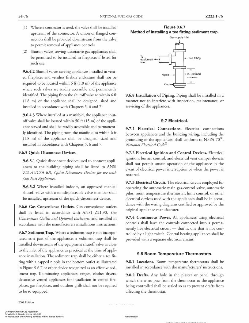
54-76 NATIONAL FUEL GAS CODE Z223.1-76
2009 Edition
(1) Where a connector is used, the valve shall be installedupstream of the connector. A union or flanged con-nection shall be provided downstream from the valveto permit removal of appliance controls.
(2) Shutoff valves serving decorative gas appliances shallbe permitted to be installed in fireplaces if listed forsuch use.
9.6.4.2 Shutoff valves serving appliances installed in vent-ed fireplaces and ventless firebox enclosures shall not berequired to be located within 6 ft (1.8 m) of the appliancewhere such valves are readily accessible and permanentlyidentified. The piping from the shutoff valve to within 6 ft(1.8 m) of the appliance shall be designed, sized andinstalled in accordance with Chapters 5, 6 and 7.
9.6.4.3 Where installed at a manifold, the appliance shut-off valve shall be located within 50 ft (15 m) of the appli-ance served and shall be readily accessible and permanent-ly identified. The piping from the manifold to within 6 ft(1.8 m) of the appliance shall be designed, sized andinstalled in accordance with Chapters 5, 6 and 7.
9.6.5 Quick-Disconnect Devices.
9.6.5.1 Quick disconnect devices used to connect appli-ances to the building piping shall be listed to ANSIZ21.41/CSA 6.9, Quick-Disconnect Devices for use withGas Fuel Appliances.
9.6.5.2 Where installed indoors, an approved manualshutoff valve with a nondisplaceable valve member shallbe installed upstream of the quick-disconnect device.
9.6.6 Gas Convenience Outlets. Gas convenience outletsshall be listed in accordance with ANSI Z21.90, GasConvenience Outlets and Optional Enclosures, and installed inaccordance with the manufacturers installations instructions.
9.6.7 Sediment Trap. Where a sediment trap is not incorpo-rated as a part of the appliance, a sediment trap shall beinstalled downstream of the equipment shutoff valve as closeto the inlet of the appliance as practical at the time of appli-ance installation. The sediment trap shall be either a tee fit-ting with a capped nipple in the bottom outlet as illustratedin Figure 9.6.7 or other device recognized as an effective sed-iment trap. Illuminating appliances, ranges, clothes dryers,decorative vented appliances for installation in vented fire-places, gas fireplaces, and outdoor grills shall not be requiredto be so equipped.
Figure 9.6.7Method of installing a tee fitting sediment trap.
9.6.8 Installation of Piping. Piping shall be installed in amanner not to interfere with inspection, maintenance, orservicing of the appliances.
9.7 Electrical.
9.7.1 Electrical Connections. Electrical connectionsbetween appliances and the building wiring, including thegrounding of the appliances, shall conform to NFPA 70®,National Electrical Code®.
9.7.2 Electrical Ignition and Control Devices. Electricalignition, burner control, and electrical vent damper devicesshall not permit unsafe operation of the appliance in theevent of electrical power interruption or when the power isrestored.
9.7.3 Electrical Circuit. The electrical circuit employed foroperating the automatic main gas-control valve, automaticpilot, room temperature thermostat, limit control, or otherelectrical devices used with the appliances shall be in accor-dance with the wiring diagrams certified or approved by theoriginal appliance manufacturer.
9.7.4 Continuous Power. All appliances using electricalcontrols shall have the controls connected into a perma-nently live electrical circuit — that is, one that is not con-trolled by a light switch. Central heating appliances shall beprovided with a separate electrical circuit.
9.8 Room Temperature Thermostats.
9.8.1 Locations. Room temperature thermostats shall beinstalled in accordance with the manufacturers’ instructions.
9.8.2 Drafts. Any hole in the plaster or panel throughwhich the wires pass from the thermostat to the appliancebeing controlled shall be sealed so as to prevent drafts fromaffecting the thermostat.
Copyright American Gas Association Provided by IHS under license with AGA
Not for ResaleNo reproduction or networking permitted without license from IHS
--`,,```,,,,````-`-`,,`,,`,`,,`---
//^:^^#^~^^""~:@":^*^~$~"#:*~::*^~:^^#~~#^~:^:@:~*:$"\\

Z223.1-77 INSTALLATION OF SPECIFIC APPLIANCES 54-77
2009 Edition
Chapter 10 Installation ofSpecific Appliances
10.1 General.
10.1.1 Application. This Chapter is applicable primarily tononindustrial-type appliances and installations and, unlessspecifically indicated, does not apply to industrial appli-ances and installations. Listed appliances shall be installedin accordance with the manufacturer’s installation instruc-tions, or as elsewhere specified in this part as applicable tothe appliance. Unlisted appliances shall be installed as spec-ified in this chapter as applicable to the appliance. For addi-tional information concerning particular gas appliances andaccessories, including industrial types, reference can bemade to the standards listed in Chapter 2 and Annex M.
10.1.2* Installation in a Bedroom or Bathroom.Appliances shall not be installed so their combustion, ven-tilation, and dilution air are obtained only from a bedroomor bathroom unless the bedroom or bathroom has therequired volume in accordance with Section 9.3.2.
10.1.3 Room Size in Comparison Calculation. Where theroom size in comparison with the size of the appliance is to becalculated, the total volume of the appliance is determinedfrom exterior dimensions and is to include fan compartmentsand burner vestibules, where used. Where the actual ceilingheight of a room is greater than 8 ft (2.4 m), the volume of theroom is figured on the basis of a ceiling height of 8 ft (2.4 m).
10.2 Air-Conditioning Appliance(Gas-Fired Air Conditioners and Heat Pumps).
10.2.1 Independent Gas Piping. Gas piping serving heat-ing appliances shall be permitted to also serve cooling appli-ances where heating and cooling appliances cannot be oper-ated simultaneously. [See Section 5.4.]
10.2.2 Connection of Gas Engine-Powered AirConditioners. To protect against the effects of normalvibration in service, gas engines shall not be rigidly con-nected to the gas supply piping.
10.2.3 Clearances for Indoor Installation. The installa-tion of air-conditioning appliances shall comply with thefollowing requirements:
(1) Listed air conditioning appliances installed in roomsthat are large in comparison with the size of the appli-ance shall be installed with clearances in accordancewith the manufacturer’s instructions. [See Table10.2.3(a) and Section 3.3.90 Room Large inComparison with Size of Appliance.]
(2) Air-conditioning appliances installed in rooms that areNOT large (such as alcoves and closets) in comparisonwith the size of the appliance shall be listed for suchinstallations and installed in accordance with the man-ufacturer’s instructions. Listed clearances shall not bereduced by the protection methods described in Table10.2.3(b), regardless of whether the enclosure is ofcombustible or noncombustible material.
Table 10.2.3(a) Clearances to Combustible Material for Unlisted Furnaces, Boilers and Air ConditionersInstalled in Rooms That Are Large in Comparison With Size of Appliances
Minimum Clearance (in.)Above and Draft Hood and
Appliance Sides of Furnace Jacket Sides Barometric Draft Single-WallPlenum Top of Boiler and Rear Front Regulator Vent Connector
I. Automatically fired, forced air or 6 — 6 18 6 18gravity system, equipped with tem-perature limit control which cannotbe set higher than 250°F (121°C).
II Automatically fired heating 6 6 6 18 18 18boilers — steam boilers operatingat not over 15 psi (103 kPa) andhot water boilers operating atnot in excess of 250°F (121°C).
III Central heating boilers and 18 18 18 18 18 18furnaces, other than I or II.
IV Air-Conditioning appliances 18 18 18 18 18 18
Note: See 10.2.3 for additional requirements for air-conditioning appliances and 10.3.2 for additional requirements for central heating boilers and furnaces.
Copyright American Gas Association Provided by IHS under license with AGA
Not for ResaleNo reproduction or networking permitted without license from IHS
--`,,```,,,,````-`-`,,`,,`,`,,`---
//^:^^#^~^^""~:@":^*^~$~"#:*~::*^~:^^#~~#^~:^:@
:~*:$"\\

54-78 NATIONAL FUEL GAS CODE Z223.1-78
2009 Edition
Table 10.2.3(b) Reduction of Clearances with Specified Forms of Protection
Where the required clearance with no protection from appliance, vent connector,or single wall metal pipe is:
36 in. 18 in. 12 in. 9 in. 6 in.
Allowable Clearances with Specified Protection (in.)
Use Col. 1 for clearances above appliance or horizontal connector. Use Col. 2 forclearances from appliance, vertical connector, and single-wall metal pipe.
Sides Sides Sides Sides Sidesand and and and and
Above Rear Above Rear Above Rear Above Rear Above RearCol. 1 Col. 2 Col. 1 Col. 2 Col. 1 Col. 2 Col. 1 Col. 2 Col. 1 Col. 2
(1) 31⁄2 in. thick masonry wallwithout ventilated air space — 24 — 12 — 9 — 6 — 5
(2) 1⁄2 in. insulation board over1-in. glass fiber or mineral wool batts 24 18 12 9 9 6 6 5 4 3
(3) 0.024 in. (nominal 24 guage)sheet metal over 1-in. glass fiber ormineral wool batts reinforced withwire on rear face with ventilatedair space 18 12 9 6 6 4 5 3 3 3
(4) 31⁄2 in. thick masonry wallwith ventilated air space — 12 — 6 — 6 — 6 — 6
(5) 0.024 in. (nominal 24 guage)sheet metal with ventilated air space 18 12 9 6 6 4 5 3 3 2
(6) 1⁄2 in. thick insulation boardwith ventilated air space 18 12 9 6 6 4 5 3 3 3
(7) 0.024 in. (nominal 24 guage)sheet metal with ventilated air spaceover 0.024 in. (nominal 24 guage)sheet metal with ventilated air space 18 12 9 6 6 4 5 3 3 3
(8) 1 in. glass fiber or mineral woolbatts sandwiched between twosheets 0.024 in. (nominal 24 guage)sheet metal with ventilated air space. 18 12 9 6 6 4 5 3 3 3
For SI units: 1 in. = 25.4 mm.Notes:(1) Reduction of clearances from combustible materials shall not interfere with combustion air, draft hood clearance and relief, and accessibilityof servicing.(2) All clearances shall be measured from the outer surface of the combustible material to the nearest point on the surface of the appliance,disregarding any intervening protection applied to the combustible material.(3) Spacers and ties shall be of noncombustible material. No spacer or tie shall be used directly opposite appliance or connector.(4) Where all clearance reduction systems use a ventilated air space, adequate provision for air circulation shall be provided as described. [SeeFigures 10.3.2.2(b) and 10.3.2.2(c)](5) There shall be at least 1 in. (25 mm) between clearance reduction systems and combustible walls and ceilings for reduction systems using aventilated air space.(6) Where a wall protector is mounted on a single flat wall away from corners, it shall have a minimum 1in. (25 mm) air gap to provide air cir-culation, the bottom and top edges, or only the side and top edges, or all edges shall be left open.(7) Mineral wool batts (blanket or board) shall have a minimum density of 8 lb/ft3 (128 kg/m) and a minimum melting point of 1500°F (816°C).(8) Insulation material used as part of a clearance reduction system shall have a thermal conductivity of 1.0 Btu in./ft2/hr-°F (0.144 W/m-°K) or less.(9) There shall be at least 1 in. (25 mm) between the appliance and the protector. In no case shall the clearance between the appliance and thecombustible surface be reduced below that allowed in Table 10.2.3(b).(10) All clearances and thicknesses are minimum; larger clearances and thicknesses are acceptable.(11) Listed single-wall connectors shall be installed in accordance with the manufacturer’s installation instructions.
Type of protection applied toand covering all surfaces ofcombustible material within thedistance specified as the requiredclearance with no protection(see Figure 9.3.2.2(a) throughFigure 9.3.2.2(c))
Copyright American Gas Association Provided by IHS under license with AGA
Not for ResaleNo reproduction or networking permitted without license from IHS
--`,,```,,,,````-`-`,,`,,`,`,,`---
//^:^^#^~^^""~:@":^*^~$~"#:*~::*^~:^^#~~#^~:^:@
:~*:$"\\

Z223.1-79 INSTALLATION OF SPECIFIC APPLIANCES 54-79
2009 Edition
(3) Unlisted air-conditioning appliances shall be installedwith clearances from combustible material of not lessthan 18 in. (460 mm) above the appliance and at thesides, front, and rear and 9 in. (230 mm) from thedraft hood.
(4) Air-conditioning appliances (listed and unlisted)installed in rooms that are large in comparison withthe size of the appliance shall be permitted to beinstalled with reduced clearances to combustible mate-rial, provided the combustible material or appliance isprotected as described in Table 10.2.3(b) [see 10.2.3(5)].
(5) Where the furnace plenum is adjacent to plaster onmetal lath or noncombustible material attached to com-bustible material, the clearance shall be measured to thesurface of the plaster or other noncombustible finishwhere the clearance specified is 2 in. (50 mm) or less.
(6) Listed air-conditioning appliances shall have the clear-ance from supply ducts within 3 ft (0.9 m) of thefurnace plenum be not less than that specified from thefurnace plenum. No clearance is necessary beyond thisdistance.
10.2.4 Assembly and Installation. Air-conditioning appli-ances shall be installed in accordance with the manufactur-er’s instructions. Unless the appliance is listed for installa-tion on a combustible surface such as a floor or roof, orunless the surface is protected in an approved manner, itshall be installed on a surface of noncombustible construc-tion with noncombustible material and surface finish andwith no combustible material against the underside thereof.
10.2.5 Furnace Plenums and Air Ducts. A furnaceplenum supplied as a part of the air-conditioning applianceshall be installed in accordance with the manufacturer’sinstructions. Where a furnace plenum is not supplied withthe appliance, any fabrication and installation instructionsprovided by the manufacturer shall be followed. Themethod of connecting supply and return ducts shall facili-tate proper circulation of air. Where the air conditioner isinstalled within a room not large in comparison with thesize of the appliance, the air circulated by the appliance shallbe handled by ducts that are sealed to the casing of theappliance and that separate the circulating air from thecombustion and ventilation air.
10.2.6* Refrigeration Coils. [See 10.3.8 and 10.3.9.]
10.2.7 Switches in Electrical Supply Line. Means forinterrupting the electrical supply to the air-conditioningappliance and to its associated cooling tower (if suppliedand installed in a location remote from the air conditioner)
shall be provided within sight of and not over 50 ft (15 m)from the air conditioner and cooling tower.
10.3 Central Heating Boilers and Furnaces.
10.3.1 Location. Central heating furnace and low-pressureboiler installations in bedrooms or bathrooms shall complywith one of the following:(1) Central heating furnaces and low-pressure boilers shall
be installed in a closet equipped with a weather-stripped door with no openings and with a self-closingdevice. All combustion air shall be obtained from theoutdoors in accordance with 9.3.3.
(2) Central heating furnaces and low-pressure boilers shallbe of the direct vent type.
10.3.2 Clearance.
10.3.2.1 Listed central heating furnaces and low-pressureboilers installed in rooms large in comparison with thesize of the appliance shall be installed with clearances inaccordance with the manufacturer’s instructions. [seeSection 3.3.90 definition Room Large in Comparison withSize of Appliance..]
10.3.2.2 Central heating furnaces and low-pressure boil-ers installed in rooms that are NOT large (such as alcovesand closets) in comparison with the size of the applianceshall be listed for such installations. Listed clearancesshall not be reduce by the protection methods describedin Table 10.2.3(b) and illustrated in Figures 10.3.2.2(a)through 10.3.2.2(c), regardless of whether the enclosureis of combustible or noncombustible material.
10.3.2.3 Unlisted central heating furnaces and low-pres-sure boilers installed in rooms that are large in compari-son with the size of the appliance shall be installed withclearances not less than those specified in Table 10.2.3(a).
10.3.2.4 Central heating furnaces and low-pressure boilers(listed and unlisted) installed in rooms that are large incomparison with the size of the appliance shall be permit-ted to be installed with reduced clearances to combustiblematerial provided the combustible material or appliance isprotected as described in Table 10.2.3(b) [see 10.3.2.2].
10.3.2.5 Front clearance shall be sufficient for servicingthe burner and the furnace or boiler.
10.3.2.6 Where the furnace plenum is adjacent to plas-ter on metal lath or noncombustible material attached tocombustible material, the clearance shall be measured tothe surface of the plaster or other noncombustible finishwhere the clearance specified is 2 in. (50 mm) or less.
Copyright American Gas Association Provided by IHS under license with AGA
Not for ResaleNo reproduction or networking permitted without license from IHS
--`,,```,,,,````-`-`,,`,,`,`,,`---
//^:^^#^~^^""~:@":^*^~$~"#:*~::*^~:^^#~~#^~:^:@
:~*:$"\\

54-80 NATIONAL FUEL GAS CODE Z223.1-80
2009 Edition
Figure 10.3.2.2(a)Extent Of Protection Necessary to Reduce
Clearances from Gas Appliance or Vent Connectors.
Notes: A equals the clearance with no protection specified in Table
10.2.3(a) and Table 12.5.1 and in the sections applying to various
types of appliances.
B equals the reduced clearance permitted in accordance with Table
10.2.3(b). The protection applied to the construction using com-
bustible materials shall extend far enough in each direction to make C
equal to A.
Figure 10.3.2.2(b)Wall Protector Clearance Reduction System.
Figure 10.3.2.2(c) Masonry ClearanceReduction System.
10.3.2.7 The clearances to these appliances shall notinterfere with combustion air, draft hood clearance andrelief, and accessibility for servicing. [See 9.2.1, Section9.3, and 12.13.7.]
10.3.2.8 Listed central heating furnaces shall have the clear-ance from supply ducts within 3 ft (0.9 m) of the furnaceplenum be not less than that specified from the furnaceplenum. No clearance is necessary beyond this distance.
10.3.2.9 Unlisted central heating furnace with tempera-ture limit controls that cannot be set higher than 250°F(121°C) shall have the clearance from supply duct with 6ft (1.8 m) of the furnace plenum be not less than 6 in. (150mm). No clearance is necessary beyond this distance.
10.3.2.10 Central heating furnaces other than those listedin 10.3.2.8 or 10.3.2.9 shall have clearances from thesupply ducts of not less than 18 in. (460 mm) from thefurnace plenum for the first 3 ft (0.9 m), then 6 in. (150mm) for the next 3 ft (0.9 m) and 1 in. (25 mm) beyond6 ft (1.8 m).
10.3.3 Assembly and Installation. A central heating boileror furnace shall be installed in accordance with the manufac-turer’s instructions and shall be installed on a floor of non-combustible construction with noncombustible flooring andsurface finish and with no combustible material against theunderside thereof, or on fire-resistive slabs or arches havingno combustible material against the underside thereof.
Exception No. 1: Appliances listed for installation on a com-bustible floor.
Exception No. 2: Installation on a floor protected in anapproved manner.
10.3.4 Temperature- or Pressure-Limiting Devices.
Copyright American Gas Association Provided by IHS under license with AGA
Not for ResaleNo reproduction or networking permitted without license from IHS
--`,,```,,,,````-`-`,,`,,`,`,,`---
//^:^^#^~^^""~:@":^*^~$~"#:*~::*^~:^^#~~#^~:^:@
:~*:$"\\
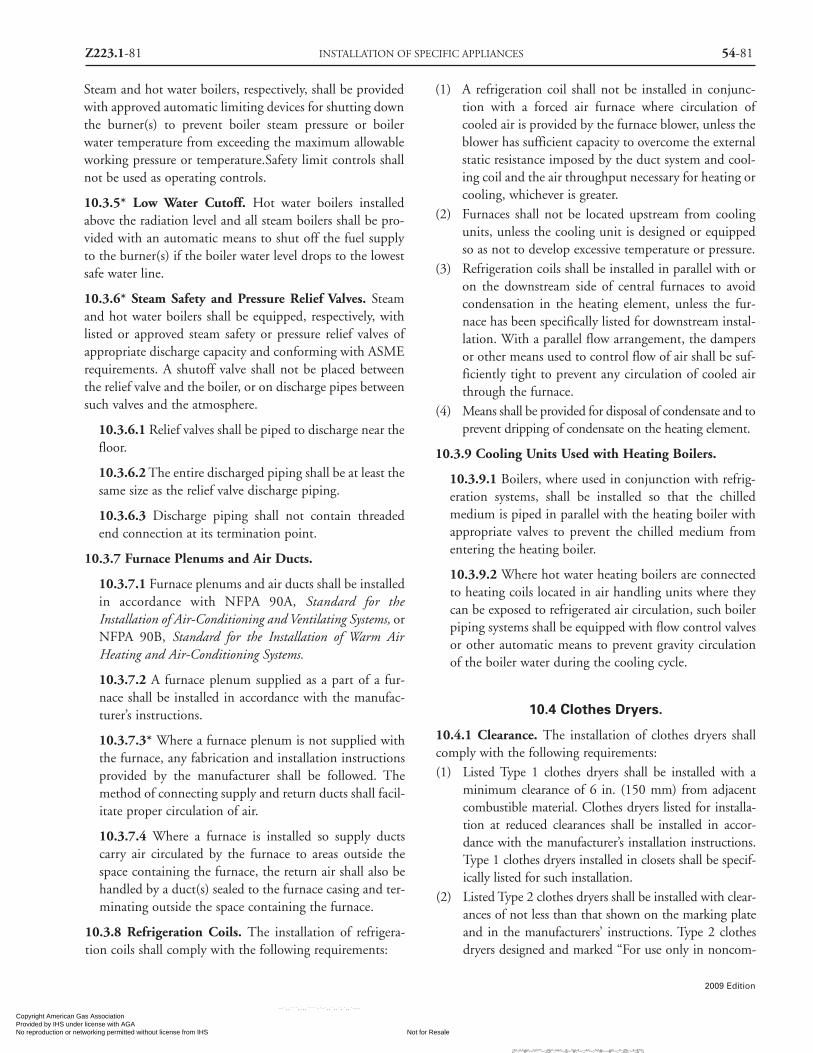
Z223.1-81 INSTALLATION OF SPECIFIC APPLIANCES 54-81
2009 Edition
Steam and hot water boilers, respectively, shall be providedwith approved automatic limiting devices for shutting downthe burner(s) to prevent boiler steam pressure or boilerwater temperature from exceeding the maximum allowableworking pressure or temperature.Safety limit controls shallnot be used as operating controls.
10.3.5* Low Water Cutoff. Hot water boilers installedabove the radiation level and all steam boilers shall be pro-vided with an automatic means to shut off the fuel supplyto the burner(s) if the boiler water level drops to the lowestsafe water line.
10.3.6* Steam Safety and Pressure Relief Valves. Steamand hot water boilers shall be equipped, respectively, withlisted or approved steam safety or pressure relief valves ofappropriate discharge capacity and conforming with ASMErequirements. A shutoff valve shall not be placed betweenthe relief valve and the boiler, or on discharge pipes betweensuch valves and the atmosphere.
10.3.6.1 Relief valves shall be piped to discharge near thefloor.
10.3.6.2 The entire discharged piping shall be at least thesame size as the relief valve discharge piping.
10.3.6.3 Discharge piping shall not contain threadedend connection at its termination point.
10.3.7 Furnace Plenums and Air Ducts.
10.3.7.1 Furnace plenums and air ducts shall be installedin accordance with NFPA 90A, Standard for theInstallation of Air-Conditioning and Ventilating Systems, orNFPA 90B, Standard for the Installation of Warm AirHeating and Air-Conditioning Systems.
10.3.7.2 A furnace plenum supplied as a part of a fur-nace shall be installed in accordance with the manufac-turer’s instructions.
10.3.7.3* Where a furnace plenum is not supplied withthe furnace, any fabrication and installation instructionsprovided by the manufacturer shall be followed. Themethod of connecting supply and return ducts shall facil-itate proper circulation of air.
10.3.7.4 Where a furnace is installed so supply ductscarry air circulated by the furnace to areas outside thespace containing the furnace, the return air shall also behandled by a duct(s) sealed to the furnace casing and ter-minating outside the space containing the furnace.
10.3.8 Refrigeration Coils. The installation of refrigera-tion coils shall comply with the following requirements:
(1) A refrigeration coil shall not be installed in conjunc-tion with a forced air furnace where circulation ofcooled air is provided by the furnace blower, unless theblower has sufficient capacity to overcome the externalstatic resistance imposed by the duct system and cool-ing coil and the air throughput necessary for heating orcooling, whichever is greater.
(2) Furnaces shall not be located upstream from coolingunits, unless the cooling unit is designed or equippedso as not to develop excessive temperature or pressure.
(3) Refrigeration coils shall be installed in parallel with oron the downstream side of central furnaces to avoidcondensation in the heating element, unless the fur-nace has been specifically listed for downstream instal-lation. With a parallel flow arrangement, the dampersor other means used to control flow of air shall be suf-ficiently tight to prevent any circulation of cooled airthrough the furnace.
(4) Means shall be provided for disposal of condensate and toprevent dripping of condensate on the heating element.
10.3.9 Cooling Units Used with Heating Boilers.
10.3.9.1 Boilers, where used in conjunction with refrig-eration systems, shall be installed so that the chilledmedium is piped in parallel with the heating boiler withappropriate valves to prevent the chilled medium fromentering the heating boiler.
10.3.9.2 Where hot water heating boilers are connectedto heating coils located in air handling units where theycan be exposed to refrigerated air circulation, such boilerpiping systems shall be equipped with flow control valvesor other automatic means to prevent gravity circulationof the boiler water during the cooling cycle.
10.4 Clothes Dryers.
10.4.1 Clearance. The installation of clothes dryers shallcomply with the following requirements:(1) Listed Type 1 clothes dryers shall be installed with a
minimum clearance of 6 in. (150 mm) from adjacentcombustible material. Clothes dryers listed for installa-tion at reduced clearances shall be installed in accor-dance with the manufacturer’s installation instructions.Type 1 clothes dryers installed in closets shall be specif-ically listed for such installation.
(2) Listed Type 2 clothes dryers shall be installed with clear-ances of not less than that shown on the marking plateand in the manufacturers’ instructions. Type 2 clothesdryers designed and marked “For use only in noncom-
Copyright American Gas Association Provided by IHS under license with AGA
Not for ResaleNo reproduction or networking permitted without license from IHS
--`,,```,,,,````-`-`,,`,,`,`,,`---
//^:^^#^~^^""~:@":^*^~$~"#:*~::*^~:^^#~~#^~:^:@:~*:$"\\

54-82 NATIONAL FUEL GAS CODE Z223.1-82
bustible locations” shall not be installed elsewhere.
(3) Unlisted clothes dryers shall be installed with clear-ances to combustible material of not less than 18 in.(460 mm). Combustible floors under unlisted clothesdryers shall be protected in an approved manner.
10.4.2 Exhausting to the Outdoors. Type 1 and Type 2clothes dryers shall be exhausted to the outdoors.
10.4.3 Provisions for Make-Up Air.
10.4.3.1 Make-up air shall be provided for Type 1clothes dryers in accordance with the manufacturers’installation instructions.
10.4.3.2 Provision for make-up air shall be provided forType 2 clothes dryers, with a minimum free area [see9.3.7.1] of 1 in.2/1,000 Btu/hr (2,200 mm2/kW) totalinput rating of the dryer(s) installed.
10.4.4 Exhaust Ducts for Type 1 Clothes Dryers.
10.4.4.1 A clothes dryer exhaust duct shall not be con-nected into any vent connector, gas vent, chimney, crawlspace, attic, or other similar concealed space.
10.4.4.2 Ducts for exhausting clothes dryers shall not beassembled with screws or other fastening means thatextend into the duct and that would catch lint andreduce the efficiency of the exhaust system.
10.4.4.3 Exhaust ducts shall be constructed of rigidmetallic material. Transition ducts used to connect thedryer to the exhaust duct shall be listed for that applica-tion or installed in accordance with the clothes dryermanufacturer’s installation instructions.
10.4.5 Exhaust Ducts for Type 2 Clothes Dryers.
10.4.5.1 Exhaust ducts for Type 2 clothes dryers shallcomply with 10.4.4.
10.4.5.2 Exhaust ducts for Type 2 clothes dryers shall beconstructed of sheet metal or other noncombustiblematerial. Such ducts shall be equivalent in strength andcorrosion resistance to ducts made of galvanized sheetsteel not less than 0.0195 in. (0.5 mm) thick.
10.4.5.3 Type 2 clothes dryers shall be equipped orinstalled with lint controlling means.
10.4.5.4 Exhaust ducts for unlisted Type 2 clothes dryersshall be installed with a minimum clearance of 6 in. (150mm) from adjacent combustible material. Where exhaustducts for Type 2 clothes dryers are installed with reducedclearances, the adjacent combustible material shall beprotected in accordance with Table 10.2.3(b).
10.4.5.5 Where ducts pass through walls, floors, or par-titions, the space around the duct shall be sealed withnoncombustible material.
10.4.5.6 Multiple installations ofType 2 clothes dryers shallbe made in a manner to prevent adverse operation due toback pressures that might be created in the exhaust systems.
10.4.6 Multiple Family or Public Use. All clothes dryersinstalled for multiple-family or public use shall be equippedwith approved safety shutoff devices and shall be installed asspecified for a Type 2 clothes dryer under 10.4.5.
10.5 Conversion Burners.
Installation of conversion burners shall conform to ANSIZ21.8, Installation of Domestic Gas Conversion Burners.
10.6 Decorative Appliances forInstallation in Vented Fireplaces.
10.6.1* Prohibited Installations. Decorative appliancesfor installation in vented fireplaces shall not be installed inbathrooms or bedrooms unless the appliance is listed andthe bedroom or bathroom has the required volume in accor-dance with Section 9.3.2.
10.6.2 Installation. A decorative appliance for installationin a vented fireplace shall be installed only in a vented fire-place having a working chimney flue and constructed ofnoncombustible materials. These appliances shall not bethermostatically controlled.
10.6.2.1 A listed decorative appliance for installation ina vented fireplace shall be installed in accordance withthe manufacturer’s installation instructions.
10.6.2.2 A decorative appliance for installation in a vent-ed fireplace where installed in a manufactured home shallbe listed for installation in manufactured homes.
10.6.2.3 An unlisted decorative appliance for installationin a vented fireplace shall be installed in a fireplace hav-ing a permanent free opening, based on appliance inputrating and chimney height equal to or greater than thatspecified in Table 10.6.2.3.
10.6.3 Fireplace Screens. A fireplace screen shall beinstalled with a decorative appliance for installation in avented fireplace.
10.7 Gas Fireplaces, Vented.
10.7.1* Prohibited Installations. Vented gas fireplaces
2009 Edition
Copyright American Gas Association Provided by IHS under license with AGA
Not for ResaleNo reproduction or networking permitted without license from IHS
--`,,```,,,,````-`-`,,`,,`,`,,`---
//^:^^#^~^^""~:@":^*^~$~"#:*~::*^~:^^#~~#^~:^:@:~*:$"\\
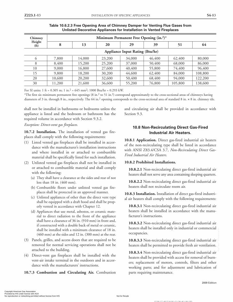
Z223.1-83 INSTALLATION OF SPECIFIC APPLIANCES 54-83
2009 Edition
shall not be installed in bathrooms or bedrooms unless theappliance is listed and the bedroom or bathroom has therequired volume in accordance with Section 9.3.2.
Exception: Direct-vent gas fireplaces.
10.7.2 Installation. The installation of vented gas fire-places shall comply with the following requirements:(1) Listed vented gas fireplaces shall be installed in accor-
dance with the manufacturer’s installation instructionsand where installed in or attached to combustiblematerial shall be specifically listed for such installation.
(2) Unlisted vented gas fireplaces shall not be installed inor attached to combustible material and shall complywith the following:(a) They shall have a clearance at the sides and rear of not
less than 18 in. (460 mm).(b) Combustible floors under unlisted vented gas fire-
places shall be protected in an approved manner.(c) Unlisted appliances of other than the direct vent type
shall be equipped with a draft hood and shall be prop-erly vented in accordance with Chapter 12.
(d) Appliances that use metal, asbestos, or ceramic mate-rial to direct radiation to the front of the applianceshall have a clearance of 36 in. (910 mm) in front and,if constructed with a double back of metal or ceramic,shall be installed with a minimum clearance of 18 in.(460 mm) at the sides and 12 in. (300 mm) at the rear.
(3) Panels, grilles, and access doors that are required to beremoved for normal servicing operations shall not beattached to the building.
(4) Direct-vent gas fireplaces shall be installed with thevent-air intake terminal in the outdoors and in accor-dance with the manufacturers’ instructions.
10.7.3 Combustion and Circulating Air. Combustion
and circulating air shall be provided in accordance withSection 9.3.
10.8 Non-Recirculating Direct Gas-FiredIndustrial Air Heaters.
10.8.1 Application. Direct gas-fired industrial air heatersof the non-recirculating type shall be listed in accordancewith ANSI Z83.4/CSA 3.7, Non-Recirculating Direct Gas-Fired Industrial Air Heaters.
10.8.2 Prohibited Installations.
10.8.2.1 Non-recirculating direct gas-fired industrial airheaters shall not serve any area containing sleeping quarters.
10.8.2.2 Non-recirculating direct gas-fired industrial airheaters shall not recirculate room air.
10.8.3 Installation. Installation of direct gas-fired industri-al air heaters shall comply with the following requirements:
10.8.3.1 Non-recirculating direct gas-fired industrial airheaters shall be installed in accordance with the manu-facturer’s instructions.
10.8.3.2 Non-recirculating direct gas-fired industrial airheaters shall be installed only in industrial or commercialoccupancies.
10.8.3.3 Non-recirculating direct gas-fired industrial airheaters shall be permitted to provide fresh air ventilation.
10.8.3.4 Non-recirculating direct gas-fired industrial airheaters shall be provided with access for removal of burn-ers; replacement of motors, controls, filters and otherworking parts; and for adjustment and lubrication ofparts requiring maintenance.
Table 10.6.2.3 Free Opening Area of Chimney Damper for Venting Flue Gases fromUnlisted Decorative Appliances for Installation in Vented Fireplaces
Minimum Permanent Free Opening (in.2)*
8 13 20 29 39 51 64
Appliance Input Rating (Btu/hr)
6 7,800 14,000 23,200 34,000 46,400 62,400 80,0008 8,400 15,200 25,200 37,000 50,400 68,000 86,000
10 9,000 16,800 27,600 40,400 55,800 74,400 96,40015 9,800 18,200 30,200 44,600 62,400 84,000 108,80020 10,600 20,200 32,600 50,400 68,400 94,000 122,20030 11,200 21,600 36,600 55,200 76,800 105,800 138,600
For SI units: 1 ft = 0.305 m; 1 in.2 = 645 mm2; 1000 Btu/hr = 0.293 kW.*The first six minimum permanent free openings (8 in.2 to 51 in.2) correspond approximately to the cross-sectional areas of chimneys havingdiameters of 3 in. through 8 in., respectively. The 64 in.2 opening corresponds to the cross-sectional area of standard 8 in. × 8 in. chimney tile.
ChimneyHeight
(ft)
Copyright American Gas Association Provided by IHS under license with AGA
Not for ResaleNo reproduction or networking permitted without license from IHS
--`,,```,,,,````-`-`,,`,,`,`,,`---
//^:^^#^~^^""~:@":^*^~$~"#:*~::*^~:^^#~~#^~:^:@:~*:$"\\

54-84 NATIONAL FUEL GAS CODE Z223.1-84
2009 Edition
10.8.4 Clearance from Combustible Materials. Non-recirculating direct gas-fired industrial air heaters shall beinstalled with a clearance from combustible materials of notless than that shown on the rating plate and the manufac-turer’s instructions.
10.8.5 Air Supply. All air to the non-recirculating directgas-fired industrial air heater shall be ducted directly fromoutdoors. Where outdoor air dampers or closing louvers areused, they shall be verified to be in the open position priorto main burner operation.
10.8.6 Atmospheric Vents or Gas Reliefs or Bleeds. Non-recirculating direct gas-fired industrial air heaters with valvetrain components equipped with atmospheric vents, gasreliefs, or bleeds shall have their vent lines, gas reliefs, orbleeds lead to a safe point outdoors. Means shall beemployed on these lines to prevent water from entering andto prevent blockage from insects and foreign matter. Anatmospheric vent line shall not be required to be provided ona valve train component equipped with a listed vent limiter.
10.8.7 Relief Openings. The design of the installation shallinclude adequate provisions to permit the non-recirculatingdirect gas-fired industrial air heater to operate at its rated air-flow without over-pressurizing the space served by the heaterby taking into account the structure’s designed infiltrationrate, properly designed relief openings, an interlocked pow-ered exhaust system, or a combination of these methods.
10.8.7.1 The structure’s designed infiltration rate andthe size of relief opening(s) shall be determined byapproved engineering methods.
10.8.7.2 Louver or counterbalanced gravity damper reliefopenings shall be permitted. Where motorized dampers orcloseable louvers are used, they shall be proved to be intheir open position prior to main burner operation.
10.8.8 Purging. Inlet ducting, when used, shall be purgedwith at least four air changes prior to an ignition attempt.
10.9 Recirculating Direct Gas-FiredIndustrial Air Heaters.
10.9.1 Application. Direct gas-fired industrial air heaters ofthe recirculating type shall be listed in accordance with ANSIZ83.18, Recirculating Direct Gas-Fired Industrial Air Heaters.
10.9.2 Prohibited Installations.
10.9.2.1 Recirculating direct gas-fired industrial air heatersshall not serve any area containing sleeping quarters.
10.9.2.2* Recirculating direct gas-fired industrial air
heaters shall not recirculate room air in buildings thatcontain flammable solids, liquids, or gases, explosivematerials, or substances that can become toxic whenexposed to flame or heat.
10.9.3 Installation. Installation of direct gas-fired industri-al air heaters shall comply with the following requirements:(1) Recirculating direct gas-fired industrial air heaters shall
be installed in accordance with the manufacturer’sinstructions.
(2) Recirculating direct gas-fired industrial air heaters shall beinstalled only in industrial or commercial occupancies.
10.9.4 Clearance from Combustible Materials.Recirculating direct gas-fired industrial air heaters shall beinstalled with a clearance from combustible materials of notless than that shown on the rating plate and the manufac-turer’s instructions.
10.9.5 Air Supply. Ventilation air to the recirculating directgas-fired industrial air heater shall be ducted directly from out-doors. Air to the recirculating direct gas-fired industrial airheater in excess of the minimum ventilation air specified on theheater’s rating plate shall be taken from the building, ducteddirectly from outdoors, or a combination of both. Where out-door air dampers or closing louvers are used, they shall be ver-ified to be in the open position prior to main burner operation.
10.9.6 Atmospheric Vents, Gas Reliefs, or Bleeds.Recirculating direct gas-fired industrial air heaters withvalve train components equipped with atmospheric vents,gas reliefs, or bleeds shall have their vent lines, gas reliefs, orbleeds lead to a safe point outdoors.
Means shall be employed on these lines to prevent waterfrom entering and to prevent blockage from insects and for-eign matter. An atmospheric vent line shall not be requiredto be provided on a valve train component equipped with alisted vent limiter.
10.9.7 Relief Openings. The design of the installation shallinclude adequate provisions to permit the recirculating directgas-fired industrial air heater to operate at its rated airflowwithout over-pressurizing the space served by the heater, bytaking into account the structure’s designed infiltration rate,properly designed relief openings, an interlocked poweredexhaust system, or a combination of these methods.
10.9.7.1 The structure’s designed infiltration rate andthe size of relief opening(s) shall be determined byapproved engineering methods.
10.9.7.2 Louver or counterbalanced gravity relief open-ings shall be permitted. Where motorized dampers orcloseable louvers are used, they shall be proved to be in
Copyright American Gas Association Provided by IHS under license with AGA
Not for ResaleNo reproduction or networking permitted without license from IHS
--`,,```,,,,````-`-`,,`,,`,`,,`---
//^:^^#^~^^""~:@":^*^~$~"#:*~::*^~:^^#~~#^~:^:@
:~*:$"\\

Z223.1-85 INSTALLATION OF SPECIFIC APPLIANCES 54-85
2009 Edition
their open position prior to main burner operation.
10.9.8 Purging. Inlet ducting, when used, shall be purgedwith at least four air changes prior to an ignition attempt.
10.10 Duct Furnaces.
10.10.1 Clearances. The installation of duct furnaces shallcomply with the following clearance requirements:(1) Listed duct furnaces shall be installed with clearances
of at least 6 in. (150 mm) between adjacent walls, ceil-ings, and floors of combustible material and the fur-nace draft hood and shall be installed in accordancewith the following:(a) Furnaces listed for installation at lesser clearances shall
be installed in accordance with the manufacturer’sinstallation instructions.
(b) In no case shall the clearance be such as to interferewith combustion air and accessibility. [See 9.2.1 andSection 9.3.]
(2) Unlisted duct furnaces shall be installed with clearancesto combustible material in accordance with the clear-ances specified for unlisted furnaces and boilers in Table10.2.3(a). Combustible floors under unlisted duct fur-naces shall be protected in an approved manner.
10.10.2 Installation of Duct Furnaces. Duct furnacesshall be installed and in accordance with the manufacturers’instructions.
10.10.3 Access Panels. The ducts connected to duct fur-naces shall have removable access panels on both theupstream and downstream sides of the furnace.
10.10.4 Location of Draft Hood and Controls. The con-trols, combustion air inlet, and draft hoods for duct fur-naces shall be located outside the ducts. The draft hoodshall be located in the same enclosure from which combus-tion air is taken.
10.10.5 Circulating Air. Where a duct furnace is installedso that supply ducts carry air circulated by the furnace toareas outside the space containing the furnace, the return airshall also be handled by a duct(s) sealed to the furnace cas-ing and terminating outside the space containing the fur-nace. The duct furnace shall be installed on the positive-pressure side of the circulating air blower.
10.10.6 Duct Furnaces Used with Refrigeration Systems.
10.10.6.1 A duct furnace shall not be installed in con-junction with a refrigeration coil where circulation ofcooled air is provided by the blower.
Exception: Where the blower has sufficient capacity to over-
come the external static resistance imposed by the duct sys-tem, furnace, and the cooling coil and the air throughputnecessary for heating or cooling, whichever is greater.
10.10.6.2 Duct furnaces used in conjunction with cool-ing appliances shall be installed in parallel with or on theupstream side of cooling coils to avoid condensationwithin heating elements. With a parallel flow arrange-ment, the dampers or other means used to control theflow of air shall be sufficiently tight to prevent any circu-lation of cooled air through the unit.
Exception: Where the duct furnace has been specifically list-ed for downstream installation.
10.10.6.3 Where duct furnaces are to be locatedupstream from cooling units, the cooling unit shall be sodesigned or equipped as to not develop excessive temper-atures or pressures.
10.10.6.4 Where a duct furnace is installed downstream ofan evaporative cooler or air washer, the heat exchanger shallbe constructed of corrosion-resistant materials. Stainlesssteel, ceramic-coated steel, and an aluminum-coated steelin which the bond between the steel and the aluminum isan iron-aluminum-alloy are considered to be corrosionresistant. Air washers operating with chilled water thatdeliver air below the dew point of the ambient air at theduct furnace are considered as refrigeration systems.
10.10.7 Installation in Commercial Garages and AircraftHangars. Duct furnaces installed in garages for more thanthree motor vehicles or in aircraft hangars shall be of a list-ed type and shall be installed in accordance with 9.1.11 and9.1.12.
10.11 Floor Furnaces.
10.11.1 Installation. The installation of floor furnaces shallcomply with the following requirements:(1) Listed floor furnaces shall be installed in accordance
with the manufacturer’s installation instructions.(2) Unlisted floor furnaces shall not be installed in com-
bustible floors.(3) Thermostats controlling floor furnaces shall not be
located in a room or space which can be separatedfrom the room or space in which the register of thefloor furnace is located.
10.11.2 Temperature Limit Controls.
10.11.2.1 Listed automatically operated floor furnacesshall be equipped with temperature limit controls.
10.11.2.2 Unlisted automatically operated floor furnaces
Copyright American Gas Association Provided by IHS under license with AGA
Not for ResaleNo reproduction or networking permitted without license from IHS
--`,,```,,,,````-`-`,,`,,`,`,,`---
//^:^^#^~^^""~:@":^*^~$~"#:*~::*^~:^^#~~#^~:^:@:~*:$"\\

54-86 NATIONAL FUEL GAS CODE Z223.1-86
2009 Edition
shall be equipped with a temperature limit controlarranged to shut off the flow of gas to the burner in theevent the temperature at the warm air outlet registerexceeds 350°F (177°C) above room temperature.
10.11.3 Combustion and Circulating Air. Combustion andcirculating air shall be provided in accordance with Section 9.3.
10.11.4 Placement. The following provisions apply to fur-naces that serve one story:
(1) Floors. Floor furnaces shall not be installed in the floorof any doorway, stairway landing, aisle, or passagewayof any enclosure, public or private, or in an exitwayfrom any such room or space.
(2) Walls and Corners. The register of a floor furnace with ahorizontal warm air outlet shall not be placed closer than6 in. (150 mm) from the nearest wall. A distance of atleast 18 in. (460 mm) from two adjoining sides of thefloor furnace register to walls shall be provided to elimi-nate the necessity of occupants walking over the warmair discharge. The remaining sides shall be a minimumof 6 in. (150 mm) from a wall. Wall register models shallnot be placed closer than 6 in. (150 mm) to a corner.
(3) Draperies. The furnace shall be placed so that a door,drapery, or similar object cannot be nearer than 12 in.(300 mm) to any portion of the register of the furnace.
10.11.5 Bracing. The space provided for the furnace shallbe framed with doubled joists and with headers not lighterthan the joists.
10.11.6 Support. Means shall be provided to support thefurnace when the floor register is removed.
10.11.7 Clearance. The lowest portion of the floor furnaceshall have at least a 6 in. (150 mm) clearance from the gen-eral ground level. A reduced clearance to a minimum of 2in. (50 mm) shall be permitted, provided the lower 6 in.(150 mm) portion of the floor furnace is sealed by the man-ufacturer to prevent entrance of water. Where these clear-ances are not present, the ground below and to the sidesshall be excavated to form a “basin-like” pit under the fur-nace so that the required clearance is provided beneath thelowest portion of the furnace. A 12 in. (300 mm) clearanceshall be provided on all sides except the control side, whichshall have an 18 in. (460 mm) clearance.
10.11.8 Access. The space in which any floor furnace isinstalled shall be accessible by an opening in the foundationnot less than 24 in. × 18 in. (610 mm × 460 mm) or a trapdoor not less than 24 in. × 24 in. (610 mm × 610 mm) in anycross section thereof, and a passageway not less than 24 in. ×18 in. (610 mm × 460 mm) in any cross section thereof.
10.11.9 Seepage Pan. Where the excavation exceeds 12 in.(300 mm) in depth or water seepage is likely to collect, awatertight copper pan, concrete pit, or other suitable mate-rial shall be used, unless adequate drainage is provided orthe appliance is sealed by the manufacturer to meet thiscondition. A copper pan shall be made of not less than 16oz/ft2 (4.9 kg/m2) sheet copper. The pan shall be anchoredin place so as to prevent floating, and the walls shall extendat least 4 in. (100 mm) above the ground level with at least6 in. (150 mm) clearance on all sides, except on the controlside, which shall have at least an 18 in. (460 mm) clearance.
10.11.10 Wind Protection. Floor furnaces shall be pro-tected, where necessary, against severe wind conditions.
10.11.11 Upper Floor Installations. Listed floor furnacesshall be permitted to be installed in an upper floor, provid-ed the furnace assembly projects below into a utility room,closet, garage, or similar nonhabitable space. In such instal-lations, the floor furnace shall be enclosed completely(entirely separated from the nonhabitable space) withmeans for air intake to meet the provisions of Section 9.3,with access for servicing, minimum furnace clearances of 6in. (150 mm) to all sides and bottom, and with the enclo-sure constructed of portland cement plaster or metal lath orother noncombustible material.
10.11.12 First Floor Installation. Listed floor furnacesinstalled in the first or ground floors of buildings shall notbe required to be enclosed unless the basements of thesebuildings have been converted to apartments or sleepingquarters, in which case the floor furnace shall be enclosed asspecified for upper floor installations and shall project intoa nonhabitable space.
10.12 Food Service Appliances, Floor-Mounted.
10.12.1 Clearance for Listed Appliances. Listed floor-mounted food service appliances, such as ranges for hotelsand restaurants, deep fat fryers, unit broilers, kettles, steamcookers, steam generators, and baking and roasting ovens,shall be installed at least 6 in. (150 mm) from combustiblematerial except that at least a 2 in. (50 mm) clearance shall bemaintained between a draft hood and combustible material.Floor-mounted food service appliances listed for installationat lesser clearances shall be installed in accordance with themanufacturer’s installation instructions. Appliances designedand marked “For use only in noncombustible locations” shallnot be installed elsewhere.
10.12.2 Clearance for Unlisted Appliances. Unlisted floor-mounted food service appliances shall be installed to providea clearance to combustible material of not less than 18 in.
Copyright American Gas Association Provided by IHS under license with AGA
Not for ResaleNo reproduction or networking permitted without license from IHS
--`,,```,,,,````-`-`,,`,,`,`,,`---
//^:^
^#^~
^^""
~:@
":^*^
~$~"
#:*~
::*^~
:^^#
~~#^
~:^:
@:~
*:$"
\\

Z223.1-87 INSTALLATION OF SPECIFIC APPLIANCES 54-87
2009 Edition
(460 mm) from the sides and rear of the appliance and fromthe vent connector and not less than 48 in. (1.2 m) abovecooking tops and at the front of the appliance. Clearances forunlisted appliances installed in partially enclosed areas such asalcoves shall not be reduced. Reduced clearance for unlistedappliances installed in rooms that are not partially enclosedshall be in accordance with Table 10.2.3(b).
10.12.3 Installation on Combustible Floor.
10.12.3.1 Listed floor-mounted food service appliancesthat are listed specifically for installation on floors con-structed of combustible material shall be permitted to beinstalled on combustible floors in accordance with themanufacturer’s instructions.
10.12.3.2 Floor-mounted food service appliances thatare not listed for mounting on a combustible floor shallbe mounted in accordance with 10.12.4 or be mountedin accordance with one of the following:(1) Where the appliance is set on legs that provide not
less than 18 in. (460 mm) open space under thebase of the appliance or where it has no burners andno portion of any oven or broiler within 18 in. (460mm) of the floor, it shall be permitted to be mount-ed on a combustible floor without special floor pro-tection, provided there is at least one sheet metalbaffle between the burner and the floor.
(2) Where the appliance is set on legs that provide notless than 8 in. (200 mm) open space under the baseof the appliance, it shall be permitted to be mount-ed on combustible floors, provided the floor underthe appliance is protected with not less than 3⁄8 in.(9.5 mm) insulating millboard covered with sheetmetal not less than 0.0195 in. (0.5 mm) thick. Thepreceding specified floor protection shall extend notless than 6 in. (150 mm) beyond the appliance onall sides.
(3) Where the appliance is set on legs that provide notless than 4 in. (100 mm) under the base of theappliance, it shall be permitted to be mounted oncombustible floors, provided the floor under theappliance is protected with hollow masonry not lessthan 4 in. (100 mm) in thickness covered with sheetmetal not less than 0.0195 in. (0.5 mm) thick. Suchmasonry courses shall be laid with ends unsealedand joints matched in such a way as to provide forfree circulation of air through the masonry.
(4) Where the appliance does not have legs at least 4 in.(100 mm) high, it shall be permitted to be mount-ed on combustible floors, provided the floor underthe appliance is protected by two courses of 4 in.
(100 mm) hollow clay tile, or equivalent, withcourses laid at right angles and with ends unsealedand joints matched in such a way as to provide forfree circulation of air through such masonry cours-es, and covered with steel plate not less than 3⁄16 in.(4.8 mm) in thickness.
10.12.4 Installation on Noncombustible Floor.
10.12.4.1 Listed floor-mounted food service appliancesthat are designed and marked “For use only in noncom-bustible locations” shall be installed on floors of non-combustible construction with noncombustible flooringand surface finish and with no combustible materialagainst the underside thereof, or on noncombustibleslabs or arches having no combustible material againstthe underside thereof.
10.12.4.2 Such construction shall in all cases extend notless than 12 in. (300 mm) beyond the appliance on allsides.
10.12.5 Combustible Material Adjacent to CookingTop. Any portion of combustible material adjacent to acooking top section of a food service range, even thoughlisted for close-to-wall installation, that is not shielded fromthe wall by a high shelf, warming closet, and so on, shall beprotected as specified in 10.12.2 for a distance of at least 2ft (0.6 m) above the surface of the cooking top.
10.12.6 Floor-Mounted Appliances with Casters. Floor-mounted appliances with casters shall be listed for such con-struction and shall be installed in accordance with the man-ufacturer’s installation instructions for limiting the move-ment of the appliance to prevent strain on the connection.
10.12.7 Level Installation. Floor-mounted food serviceappliances shall be installed level on a firm foundation.
10.12.8* Ventilation. Means shall be provided to properlyventilate the space in which a food service appliance isinstalled to permit proper combustion of the gas.
10.13 Food Service AppliancesCounter Appliances.
10.13.1 Vertical Clearance. A vertical distance of not lessthan 48 in. (1.2 m) shall be provided between the top of allfood service hot plates and griddles and combustible material.
10.13.2 Clearance for Listed Appliances. Listed foodservice counter appliances such as hot plates and griddles,food and dish warmers, and coffee brewers and urns, whereinstalled on combustible surfaces, shall be set on their ownbases or legs and shall be installed with a minimum hori-
Copyright American Gas Association Provided by IHS under license with AGA
Not for ResaleNo reproduction or networking permitted without license from IHS
--`,,```,,,,````-`-`,,`,,`,`,,`---
//^:^^#^~^^""~:@":^*^~$~"#:*~::*^~:^^#~~#^~:^:@:~*:$"\\

54-88 NATIONAL FUEL GAS CODE Z223.1-88
2009 Edition
zontal clearance of 6 in. (150 mm) from combustible mate-rial, except that at least a 2 in. (50 mm) clearance shall bemaintained between a draft hood and combustible materi-al. Food service counter appliances listed for installation atlesser clearances shall be installed in accordance with themanufacturer’s installation instructions.
10.13.3 Clearance for Unlisted Appliances. Unlisted foodservice hot plates and griddles shall be installed with a hor-izontal clearance from combustible material of not less than18 in. (460 mm). Unlisted gas food service counter appli-ances, including coffee brewers and urns, waffle bakers, andhot water immersion sterilizers, shall be installed with a hor-izontal clearance from combustible material of not less than12 in. (300 mm). Reduced clearances for gas food servicecounter appliances shall be in accordance with Table10.2.3(b). Unlisted food and dish warmers shall be installedwith a horizontal clearance from combustible material ofnot less than 6 in. (150 mm).
10.13.4 Mounting of Unlisted Appliances. Unlisted foodservice counter appliances shall not be set on combustiblematerial unless they have legs that provide not less than 4 in.(100 mm) of open space below the burners and the com-bustible surface is protected with insulating millboard at least1⁄4 in. (6 mm) thick covered with sheet metal not less than0.0122 in. (0.3 mm) thick, or with equivalent protection
10.14 Hot Plates and Laundry Stoves.
10.14.1 Listed domestic hot plates and laundry stovesinstalled on combustible surfaces shall be set on their ownlegs or bases. They shall be installed with minimum horizon-tal clearances of 6 in. (150 mm) from combustible material.
10.14.2 Unlisted domestic hot plates and laundry stovesshall be installed with horizontal clearances to combustiblematerial of not less than 12 in. (300 mm). Combustible sur-faces under unlisted domestic hot plates and laundry stovesshall be protected in an approved manner.
10.14.3 The vertical distance between tops of all domestichot plates and laundry stoves and combustible material shallbe at least 30 in. (760 mm).
10.15 Household Cooking Appliances.
10.15.1 Floor-Mounted Units.
10.15.1.1 Clearance from Combustible Material. Theclearances specified as follows shall not interfere withcombustion air, accessibility for operation, and servicing:(1) Listed floor-mounted household cooking appliances,
where installed on combustible floors, shall be set ontheir own bases or legs and shall be installed in accor-dance with the manufacturer’s installation instructions.
(2) Listed household cooking appliances with listed gasroom heater sections shall be installed so that thewarm air discharge side shall have a minimum clear-ance of 18 in. (460 mm) from adjacent combustiblematerial. A minimum clearance of 36 in. (910 mm)shall be provided between the top of the heater sec-tion and the bottom of cabinets.
(3) Listed household cooking appliances that include asolid or liquid fuel-burning section shall be spacedfrom combustible material and otherwise installedin accordance with the manufacturer’s installationinstructions for the supplementary fuel section ofthe appliance.
(4) Unlisted floor-mounted household cooking appli-ances shall be installed with at least 6 in. (150 mm)clearance at the back and sides to combustible mate-rial. Combustible floors under unlisted appliancesshall be protected in an approved manner.
10.15.1.2 Vertical Clearance above Cooking Top.Household cooking appliances shall have a vertical clear-ance above the cooking top of not less than 30 in. (760mm) to combustible material or metal cabinets. A mini-mum clearance of 24 in. (610 mm) is permitted whenone of the following is installed:(1) The underside of the combustible material or metal
cabinet above the cooking top is protected with notless than 1⁄4 in. (6 mm) insulating millboard coveredwith sheet metal not less than 0.0122 in. (0.3 mm)thick.
(2) A metal ventilating hood of sheet metal not lessthan 0.0122 in. (0.3 mm) thick is installed abovethe cooking top with a clearance of not less than 1⁄4in. (6 mm) between the hood and the underside ofthe combustible material or metal cabinet, and thehood is at least as wide as the appliance and is cen-tered over the appliance.
(3) A listed cooking appliance or microwave oven isinstalled over a listed cooking appliance and willconform to the terms of the upper manufacturer’sinstallation instructions.
10.15.1.3 Level Installation. Cooking appliances shallbe installed so that the cooking top or oven racks are level.
10.15.2 Built-In Units.
10.15.2.1 Installation. Listed built-in household cook-ing appliances shall be installed in accordance with the
Copyright American Gas Association Provided by IHS under license with AGA
Not for ResaleNo reproduction or networking permitted without license from IHS
--`,,```,,,,````-`-`,,`,,`,`,,`---
//^:^^#^~^^""~:@":^*^~$~"#:*~::*^~:^^#~~#^~:^:@:~*:$"\\

Z223.1-89 INSTALLATION OF SPECIFIC APPLIANCES 54-89
2009 Edition
manufacturer’s installation instructions. The installationshall not interfere with combustion air, accessibility foroperation, and servicing. Unlisted built-in householdcooking appliances shall not be installed in, or adjacentto, combustible material.
10.15.2.2 Vertical Clearance. Built-in top (or surface)cooking appliances shall have a vertical clearance abovethe cooking top of not less than 30 in. (760 mm) to com-bustible material or metal cabinets. A minimum clear-ance of 24 in. (610 mm) is permitted when one of thefollowing is installed:
(1) The underside of the combustible material or metalcabinet above the cooking top is protected with notless than 1⁄4 in. (6 mm) insulating millboard coveredwith sheet metal not less than 0.0122 in. (0.3 mm)thick.
(2) A metal ventilating hood of sheet metal not lessthan 0.0122 in. (0.3 mm) thick is installed abovethe cooking top with a clearance of not less than 1⁄4in. (6 mm) between the hood and the underside ofthe combustible material or metal cabinet, and thehood is at least as wide as the appliance and is cen-tered over the appliance.
(3) A listed cooking appliance or microwave oven isinstalled over a listed cooking appliance and willconform to the terms of the upper manufacturer’sinstallation instructions.
10.15.2.3 Horizontal Clearance. The minimum hori-zontal distance from the center of the burner head(s) of alisted top (or surface) cooking appliance to vertical com-bustible walls extending above the top panel shall be notless than that distance specified by the permanent mark-ing on the appliance.
10.15.2.4 Level Installation. Built-in household cook-ing appliances shall be installed so that the cooking top,broiler pan, or oven racks are level.
10.16 Illuminating Appliances.
10.16.1 Clearances for Listed Appliances. Listed illumi-nating appliances shall be installed in accordance with themanufacturer’s installation instructions.
10.16.2 Clearances for Unlisted Appliances.
10.16.2.1 Enclosed Type. Clearance shall comply withthe following:
(1) Unlisted enclosed illuminating appliances installedoutdoors shall be installed with clearances in any
direction from combustible material of not less than12 in. (300 mm).
(2) Unlisted enclosed illuminating appliances installedindoors shall be installed with clearances in anydirection from combustible material of not less than18 in. (460 mm).
10.16.2.2 Open-Flame Type. Clearance shall complywith the following:(1) Unlisted open-flame illuminating appliances
installed outdoors shall have clearances from com-bustible material not less than that specified in Table10.16.2.2. The distance from ground level to thebase of the burner shall be a minimum of 7 ft (2.1m) where installed within 2 ft (0.6 m) of walkways.Lesser clearances shall be permitted to be used whereacceptable to the authority having jurisdiction.
(2) Unlisted open-flame illuminating appliances installedoutdoors shall be equipped with a limiting orifice orother limiting devices that will maintain a flameheight consistent with the clearance from com-bustible material, as given in Table 10.16.2.2.
(3) Appliances designed for flame heights in excess of30 in. (760 mm) shall be permitted to be installedif acceptable to the authority having jurisdiction.Such appliances shall be equipped with a safetyshutoff device or automatic ignition.
(4) Unlisted open-flame illuminating appliances installedindoors shall have clearances from combustible mate-rial acceptable to the authority having jurisdiction.
Table 10.16.2.2 Clearances for Unlisted OutdoorOpen-Flame Illuminating Appliances
Flame Height Minimum Clearance fromAbove Burner Combustible Material (ft)*
Head (in.) Horizontal Vertical
12 2 6
18 3 8
24 3 10
30 4 12
For SI units: 1 in. = 25.4 mm; 1 ft = 0.305 m.*Measured from the nearest portion of the burner head.
10.16.3 Mounting on Buildings. Illuminating appliancesdesigned for wall or ceiling mounting shall be securelyattached to substantial structures in such a manner that theyare not dependent on the gas piping for support.
10.16.4 Mounting on Posts. Illuminating appliancesdesigned for post mounting shall be securely and rigidly
Copyright American Gas Association Provided by IHS under license with AGA
Not for ResaleNo reproduction or networking permitted without license from IHS
--`,,```,,,,````-`-`,,`,,`,`,,`---
//^:^^#^~^^""~:@":^*^~$~"#:*~::*^~:^^#~~#^~:^:@
:~*:$"\\

54-90 NATIONAL FUEL GAS CODE Z223.1-90
attached to a post. Posts shall be rigidly mounted. Thestrength and rigidity of posts greater than 3 ft (0.9 m) inheight shall be at least equivalent to that of a 21⁄2 in. (64mm) diameter post constructed of 0.064 in. (1.6 mm) thicksteel or a 1 in. (25 mm) Schedule 40 steel pipe. Posts 3 ft(0.9 m) or less in height shall not be smaller than a 3⁄4 in.Schedule 40 steel pipe. Drain openings shall be providednear the base of posts where there is a possibility of watercollecting inside them.
10.16.5 Appliance Pressure Regulators. Where an appliancepressure regulator is not supplied with an illuminating applianceand the service line is not equipped with a service pressure reg-ulator, an appliance pressure regulator shall be installed in theline serving one or more illuminating appliances.
10.17 Incinerators, Commercial-Industrial.
Commercial-industrial-type incinerators shall be construct-ed and installed in accordance with NFPA 82, Standard onIncinerators and Waste and Linen Handling Systems andEquipment.
10.18 Infrared Heaters.
10.18.1 Support. Suspended-type infrared heaters shall befixed in position independent of gas and electric supplylines. Hangers and brackets shall be of noncombustiblematerial. Heaters subject to vibration shall be provided withvibration-isolating hangers.
10.18.2 Clearance. The installation of infrared heatersshall comply with the following clearance requirements:(1) Listed heaters shall be installed with clearances from
combustible material in accordance with the manufac-turer’s installation instructions.
(2) Unlisted heaters shall be installed in accordance withclearances from combustible material acceptable to theauthority having jurisdiction.
(3) In locations used for the storage of combustible mate-rials, signs shall be posted to specify the maximum per-missible stacking height to maintain required clear-ances from the heater to the combustibles.
10.18.3 Combustion and Ventilation Air.
10.18.3.1 Where unvented infrared heaters are used,natural or mechanical means shall be provided to supplyand exhaust at least 4 ft3/min/1,000 Btu/hr (0.38m3/min/kW) input of installed heaters.
10.18.3.2 Exhaust openings for removing flue productsshall be above the level of the heaters.
10.18.4 Installation in Commercial Garages and AircraftHangars. Overhead heaters installed in garages for morethan three motor vehicles or in aircraft hangars shall be of alisted type and shall be installed in accordance with 9.1.11and 9.1.12.
10.19 Open-Top Broiler Units.
10.19.1 Listed Units. Listed open-top broiler units shall beinstalled in accordance with the manufacturer’s installationinstructions.
10.19.2 Unlisted Units. Unlisted open-top broiler units shallbe installed in accordance with the manufacturers’ instruc-tions but shall not be installed in combustible material.
10.19.3 Protection above Domestic Units. Domesticopen-top broiler units shall be provided with a metal venti-lating hood not less than 0.0122 in. (0.3 mm) thick with aclearance of not less than 1⁄4 in. (6 mm) between the hoodand the underside of combustible material or metal cabi-nets. A clearance of at least 24 in. (610 mm) shall be main-tained between the cooking top and the combustible mate-rial or metal cabinet, and the hood shall be at least as wideas the open-top broiler unit and centered over the unit.Listed domestic open-top broiler units incorporating anintegral exhaust system and listed for use without a venti-lating hood need not be provided with a ventilating hood ifinstalled in accordance with 10.15.1.2 (1).
10.19.4 Commercial Units. Commercial open-top broilerunits shall be provided with ventilation in accordance withNFPA 96, Standard for Ventilation Control and FireProtection of Commercial Cooking Operations.
10.20 Outdoor Cooking Appliances.
10.20.1 Listed Units. Listed outdoor cooking appliancesshall be installed in accordance with the manufacturer’sinstallation instructions.
10.20.2 Unlisted Units. Unlisted outdoor cooking appli-ances shall be installed outdoors with clearances to com-bustible material of not less than 36 in. (910 mm) at thesides and back and not less than 48 in. (1,220 mm) at thefront. In no case shall the appliance be located under over-head combustible construction.
10.21 Pool Heaters.
10.21.1 Location. A pool heater shall be located or pro-tected so as to minimize accidental contact of hot surfacesby persons.
2009 Edition
Copyright American Gas Association Provided by IHS under license with AGA
Not for ResaleNo reproduction or networking permitted without license from IHS
--`,,```,,,,````-`-`,,`,,`,`,,`---
//^:^
^#^~
^^""
~:@
":^*^
~$~"
#:*~
::*^~
:^^#
~~#^
~:^:
@:~
*:$"
\\

Z223.1-91 INSTALLATION OF SPECIFIC APPLIANCES 54-91
2009 Edition
10.21.2 Clearance. The installation of pool heaters shallcomply with the following requirements:(1) In no case shall the clearances be such as to interfere
with combustion air, draft hood or vent terminal clear-ance and relief, and accessibility for servicing.
(2) A listed pool heater shall be installed in accordancewith the manufacturer’s installation instructions.
(3) An unlisted pool heater shall be installed with a mini-mum clearance of 12 in. (300 mm) on all sides and therear. A combustible floor under an unlisted pool heatershall be protected in an approved manner.
10.21.3 Temperature- or Pressure-Limiting Devices.
10.21.3.1 An unlisted pool heater shall be provided withovertemperature protection or overtemperature and over-pressure protection by means of an approved device(s).
10.21.3.2 Where a pool heater is provided with overtem-perature protection only and is installed with any device inthe discharge line of the heater that can restrict the flow ofwater from the heater to the pool (such as a check valve,shutoff valve, therapeutic pool valving, or flow nozzles), apressure relief valve shall be installed either in the heater orbetween the heater and the restrictive device.
10.21.4 Bypass Valves. Where an integral bypass system isnot provided as a part of the pool heater, a bypass line andvalve shall be installed between the inlet and outlet pipingfor use in adjusting the flow of water through the heater.
10.21.5 Venting. A pool heater listed for outdoor installa-tion shall be installed with the venting means supplied bythe manufacturer and in accordance with the manufacturer’sinstructions. [See 12.3.5, 12.3.6, 12.4.3, and Section 12.9.]
10.22 Refrigerators.
10.22.1 Clearance. Refrigerators shall be provided withclearances for ventilation at the top and back in accordancewith the manufacturers’ instructions. Where such instruc-tions are not available, at least 2 in. (50 mm) shall be pro-vided between the back of the refrigerator and the wall andat least 12 in. (300 mm) above the top.
10.22.2 Venting or Ventilating Kits Approved for Usewith a Refrigerator. Where an accessory kit is used for con-veying air for burner combustion or unit cooling to therefrigerator from areas outside the room in which it is locat-ed, or for conveying combustion products diluted with aircontaining waste heat from the refrigerator to areas outsidethe room in which it is located, the kit shall be installed inaccordance with the refrigerator manufacturer’s instructions.
10.23 Room Heaters.
10.23.1* Prohibited Installations. Unvented room heatersshall not be installed in bathrooms or bedrooms.
Exception No. 1: Where approved by the authority having juris-diction, one listed wall-mounted unvented room heaterequipped with an oxygen depletion safety shutoff system shall bepermitted to be installed in a bathroom, provided that the inputrating does not exceed 6,000 Btu/hr (1,760 W/hr) and combus-tion and ventilation air is provided as specified in 10.1.2.
Exception No. 2: Where approved by the authority havingjurisdiction, one listed wall-mounted unvented room heaterequipped with an oxygen depletion safety shutoff system shall bepermitted to be installed in a bedroom, provided that the inputrating does not exceed 10,000 Btu/hr (2,930 W/hr) and com-bustion and ventilation air is provided as specified in 10.1.2.
10.23.2 Unvented room heaters shall be listed in accordancewith ANSI Z21.11.2, Gas-Fired Room Heaters — VolumneII, Unvented Room Heaters, and shall be installed in accor-dance with the manufacturer’s installation instructions.
10.23.3 Installations in Institutions. Room heaters shallnot be installed in the following occupancies:1) Residential board and care2) Health care.
10.23.4 Clearance. A room heater shall be placed so as notto cause a hazard to walls, floors, curtains, furniture, doorswhen open, and so on, and to the free movements of per-sons within the room. Heaters designed and marked “Foruse in noncombustible fireplace only” shall not be installedelsewhere. Listed room heaters shall be installed in accor-dance with the manufacturer’s installation instructions. Inno case shall the clearances be such as to interfere with com-bustion air and accessibility. Unlisted room heaters shall beinstalled with clearances from combustible material not lessthan the following:(1) Circulating Type. Room heaters having an outer jacket
surrounding the combustion chamber, arranged withopenings at top and bottom so that air circulates betweenthe inner and outer jacket, and without openings in theouter jacket to permit direct radiation, shall have clear-ance at sides and rear of not less than 12 in. (300 mm).
(2) Radiating Type. Room heaters other than those of circu-lating type described in 10.23.4 (1) shall have clearanceat sides and rear of not less than 18 in. (460 mm), exceptthat heaters that make use of metal, asbestos, or ceram-ic material to direct radiation to the front of the heatershall have a clearance of 36 in. (910 mm) in front and,if constructed with a double back of metal or ceramic,shall be permitted to be installed with a clearance of 18in. (460 mm) at sides and 12 in. (300 mm) at rear.
Copyright American Gas Association Provided by IHS under license with AGA
Not for ResaleNo reproduction or networking permitted without license from IHS
--`,,```,,,,````-`-`,,`,,`,`,,`---
//^:^
^#^~
^^""
~:@
":^*^
~$~"
#:*~
::*^~
:^^#
~~#^
~:^:
@:~
*:$"
\\

54-92 NATIONAL FUEL GAS CODE Z223.1-92
Combustible floors under unlisted room heaters shall beprotected in an approved manner.
10.23.5 Wall-Type Room Heaters. Wall-type room heatersshall not be installed in or attached to walls of combustiblematerial unless listed for such installation.
10.24 Stationary Gas Engines.
10.24.1 Stationary gas engines shall not be rigidly connect-ed to the gas supply piping.
10.24.2 The installation of gas engines shall conform withNFPA 37, Standard for the Installation and Use of StationaryCombustion Engines and Gas Turbines.
10.25 Gas-Fired Toilets.
10.25.1 Clearance. A listed gas-fired toilet shall be installedin accordance with the manufacturer’s installation instruc-tions, provided that the clearance in any case is sufficient toafford ready accessibility for use, cleanout, and necessaryservicing.
10.25.2 Installation on Combustible Floors. Listed gas-fired toilets installed on combustible floors shall be listed forsuch installation.
10.25.3 Installation of Vent or Vent Connectors. Vents orvent connectors that are capable of being contacted duringcasual use of the room in which the toilet is installed shallbe protected or shielded to prevent such contact.
10.26 Unit Heaters.
10.26.1 Support. Suspended-type unit heaters shall besafely and adequately supported with due considerationgiven to their weight and vibration characteristics. Hangersand brackets shall be of noncombustible material.
10.26.2 Clearance.
10.26.2.1 Suspended-Type Unit Heaters. Suspended-type unit heaters shall comply with the followingrequirements:(1) A listed unit heater shall be installed with clearances
from combustible material of not less than 18 in.(460 mm) at the sides, 12 in. (300 mm) at the bot-tom, and 6 in. (150 mm) above the top where theunit heater has an internal draft hood, or 1 in. (25mm) above the top of the sloping side of a verticaldraft hood. A unit heater listed for reduced clear-ances shall be installed in accordance with the man-
ufacturer’s installation instructions.
(2) Unlisted unit heaters shall be installed with clear-ances to combustible material of not less than 18 in.(460 mm).
(3) Clearances for servicing shall be in accordance withthe manufacturers’ recommendations contained inthe installation instructions.
10.26.2.2 Floor-Mounted-Type Unit Heaters. Floor-mounted-type unit heaters shall comply with the follow-ing requirements:
(1) A listed unit heater shall be installed with clearancesfrom combustible material at the back and one sideonly of not less than 6 in. (150 mm). Where the fluegases are vented horizontally, the 6 in. (150 mm)clearance shall be measured from the draft hood orvent instead of the rear wall of the unit heater. Aunit heater listed for reduced clearances shall beinstalled in accordance with the manufacturer’sinstallation instructions.
(2) Floor-mounted-type unit heaters installed on com-bustible floors shall be listed for such installation.
(3) Combustible floors under unlisted floor-mountedunit heaters shall be protected in an approved manner.
(4) Clearances for servicing shall be in accordance withthe manufacturers’ recommendations contained inthe installation instructions.
10.26.3 Combustion and Circulating Air. Combustionand circulating air shall be provided in accordance withSection 9.3.
10.26.4 Ductwork. A unit heater shall not be attached to awarm air duct system unless listed and marked for suchinstallation.
10.26.5 Installation in Commercial Garages and AircraftHangars. Unit heaters installed in garages for more than threemotor vehicles or in aircraft hangars shall be of a listed typeand shall be installed in accordance with 9.1.11 and 9.1.12.
10.27 Wall Furnaces.
10.27.1 Installation.
10.27.1.1 Listed wall furnaces shall be installed in accor-dance with the manufacturer’s installation instructions.Wall furnaces installed in or attached to combustiblematerial shall be listed for such installation.
10.27.1.2 Unlisted wall furnaces shall not be installed inor attached to combustible material.
2009 Edition
Copyright American Gas Association Provided by IHS under license with AGA
Not for ResaleNo reproduction or networking permitted without license from IHS
--`,,```,,,,````-`-`,,`,,`,`,,`---
//^:^
^#^~
^^""
~:@
":^*^
~$~"
#:*~
::*^~
:^^#
~~#^
~:^:
@:~
*:$"
\\

Z223.1-93 INSTALLATION OF SPECIFIC APPLIANCES 54-93
2009 Edition
10.27.1.3 Vented wall furnaces connected to a Type B-W gas vent system listed only for single story shall beinstalled only in single-story buildings or the top story ofmultistory buildings. Vented wall furnaces connected toa Type B-W gas vent system listed for installation in mul-tistory buildings shall be permitted to be installed in sin-gle-story or multistory buildings. Type B-W gas ventsshall be attached directly to a solid header plate thatserves as a firestop at that point and that shall be permit-ted to be an integral part of the vented wall furnace. Thestud space in which the vented wall furnace is installedshall be ventilated at the first ceiling level by installationof the ceiling plate spacers furnished with the gas vent.Firestop spacers shall be installed at each subsequent ceil-ing or floor level penetrated by the vent. [See Figure10.27.1.3 for Type B-W gas vent installation.]
Figure 10.27.1.3 Installation of Type B-W gas ventsfor vented wall furnaces.
10.27.1.4 Direct-vent wall furnaces shall be installed withthe vent-air intake terminal in the outdoors. The thicknessof the walls on which the furnace is mounted shall be with-in the range of wall thickness marked on the furnace andcovered in the manufacturers’ installation instructions.
10.27.1.5 Panels, grilles, and access doors that are requiredto be removed for normal servicing operations shall not beattached to the building. [For additional information on theventing of wall furnaces, see Chapter 12.]
10.27.2 Location. Wall furnaces shall be located so as notto cause a hazard to walls, floors, curtains, furniture, ordoors. Wall furnaces installed between bathrooms andadjoining rooms shall not circulate air from bathrooms toother parts of the building.
10.27.3 Combustion and Circulating Air. Combustionand circulating air shall be provided in accordance withSection 9.3.
10.28 Water Heaters.
10.28.1 Installations in Bedrooms and Bathrooms.Water heater installations in bedrooms and bathrooms shallcomply with one of the following:
(1) Water heaters shall be installed in a closet equippedwith a weather-stripped door with no openings andwith a self-closing device. All combustion air shall beobtained from the outdoors in accordance with 9.3.3.
(2) Water heater shall be of the direct vent type.
10.28.2 Clearance.
10.28.2.1 The clearances shall not be such as to interferewith combustion air, draft hood clearance and relief, andaccessibility for servicing. Listed water heaters shall beinstalled in accordance with the manufacturer’s installa-tion instructions.
10.28.2.2 Unlisted water heaters shall be installed with aclearance of 12 in. (300 mm) on all sides and rear.Combustible floors under unlisted water heaters shall beprotected in an approved manner.
10.28.3 Pressure-Limiting Devices. A water heater installa-tion shall be provided with overpressure protection by meansof an approved, listed device installed in accordance with themanufacturer’s installation instructions. The pressure settingof the device shall exceed the water service pressure and shallnot exceed the maximum pressure rating of the water heater.
10.28.4 Temperature-Limiting Devices. A water heaterinstallation or a hot water storage vessel installation shall beprovided overtemperature protection by means of anapproved, listed device installed in accordance with themanufacturer’s installation instructions.
10.28.5 Temperature, Pressure, and Vacuum ReliefDevices. Temperature, pressure, and vacuum relief devices orcombinations thereof, and automatic gas shutoff devices, shallbe installed in accordance with the manufacturer’s installationinstructions. A shutoff valve shall not be placed between therelief valve and the water heater or on discharge pipes between
Copyright American Gas Association Provided by IHS under license with AGA
Not for ResaleNo reproduction or networking permitted without license from IHS
--`,,```,,,,````-`-`,,`,,`,`,,`---
//^:^^#^~^^""~:@":^*^~$~"#:*~::*^~:^^#~~#^~:^:@:~*:$"\\

54-94 NATIONAL FUEL GAS CODE Z223.1-94
2009 Edition
such valves and the atmosphere. The hourly Btu dischargecapacity or the rated steam relief capacity of the device shallnot be less than the input rating of the water heater.
10.28.6 Automatic Instantaneous Type: Cold WaterSupply. The water supply to an automatic instantaneouswater heater that is equipped with a water flow-actuatedcontrol shall be such as to provide sufficient pressure toproperly operate the control when water is drawn from thehighest faucet served by the heater.
10.28.7* Antisiphon Devices. Means acceptable to theauthority having jurisdiction shall be provided to preventsiphoning in any water heater or any tank to which a circu-lating water heater that incorporates a cold water inlet tubeis attached.
10.29 Compressed Natural Gas (CNG)Vehicular Fuel Systems.
The installation of compressed natural gas (CNG) fueling(dispensing) systems shall conform with NFPA 52, VehicularFuel Systems Code.
10.30 Appliances for Installationin Manufactured Housing.
Appliances installed in manufactured housing after the ini-tial sale shall be listed for installation in manufactured hous-ing, or approved, and shall be installed in accordance withthe requirements of this code and the manufacturers’ instal-lation instructions. Appliances installed in the living spaceof manufactured housing shall be in accordance with therequirements of 9.3.
10.31 Fuel Cell Power Plants.
Fuel cell power plants with a power output of less than 50kW shall be listed and installed in accordance with the man-ufacturer’s instructions. Fuel cell power plants with a poweroutput of greater than 50 kW shall be installed in accor-dance with NFPA 853, Standard for Installation ofStationary Fuel Cell Power Systems.
10.32 Outdoor Open-FlameDecorative Appliances.
Permanently fixed-in-place outdoor open-flame decorativeappliances shall be installed in accordance with 10.32.1through 10.32.3
10.32.1 Listed Units. Listed outdoor open-flame decora-tive appliances shall be installed in accordance with themanufacturer’s installation instructions.
10.32.2 Unlisted Units. Unlisted outdoor open-flame dec-orative appliances shall be installed outdoors in accordancewith the manufacturer’s installation instructions and withclearances to combustible material of not less than 36 in.(910 mm) from the sides. In no case shall the appliance belocated under overhead combustible construction.
10.32.3 Connection to the Piping System. The connec-tion to the gas piping system shall be in accordance with9.6.1 (1), (2), (4) or (5).
Chapter 11 Procedures to Be Followedto Place Appliance in Operation
11.1 Adjusting the Burner Input.
11.1.1* Adjusting Input. The input rate of the burnershall be adjusted to the proper value in accordance with theappliance manufacturer’s instructions.
11.1.1.1 The input rate can be adjusted by either chang-ing the size of a fixed orifice, changing the adjustment ofan adjustable orifice, or readjusting the appliance’s gaspressure regulator outlet pressure (where a regulator isprovided in the appliance).
11.1.1.2 Input rate can be determined by either one ofthe following:
(1) Checking burner input by using a gas meter.
(2) Checking burner input by using orifice pressuredrop and orifice size.
11.1.1.3 Overfiring shall be prohibited.
11.1.2 High Altitude. Gas input ratings of appliances shallbe used for elevations up to 2,000 ft (600 m). The input rat-ings of appliances operating at elevations above 2,000 ft (600m) shall be reduced in accordance with one of the followingmethods:
(1) 4 percent for each 1,000 ft (300 m) above sea levelbefore selecting appropriately sized appliance.
(2) As permitted by the authority having jurisdiction.
(3) Listed appliances derated in accordance with the man-ufacturer’s installation instructions shall be permitted.
Copyright American Gas Association Provided by IHS under license with AGA
Not for ResaleNo reproduction or networking permitted without license from IHS
--`,,```,,,,````-`-`,,`,,`,`,,`--- //^:^
^#^~
^^""
~:@
":^*^
~$~"
#:*~
::*^~
:^^#
~~#^
~:^:
@:~
*:$"
\\

Z223.1-95 VENTING OF APPLIANCES 54-95
2009 Edition
11.2* Primary Air Adjustment.
The primary air for injection (Bunsen)-type burners shall beadjusted for proper flame characteristics in accordance withthe appliance’s manufacturers’ instructions. After setting theprimary air, the adjustment means shall be secured in position.
11.3 Safety Shutoff Devices.
Where a safety shutoff device is provided, it shall be checkedfor proper operation and adjustment in accordance with theappliance manufacturer’s instructions. Where the device doesnot function properly to turn off the gas supply in the event ofpilot outage or other improper operation, it shall be properlyserviced or replaced with a new device.
11.4 Automatic Ignition.
Appliances supplied with means for automatic ignition shallbe checked for proper operation. If necessary, proper adjust-ments shall be made.
11.5 Protective Devices.
All protective devices furnished with the appliance, such asa limit control, fan control to blower, temperature and pres-sure relief valve, low-water cutoff device, manual operatingfeatures, shall be checked for proper operation.
11.6* Checking the Draft.
Vent-connected appliances shall be operated for several min-utes and checked to see that the combustion products aregoing up the chimney or gas vent properly, by passing a light-ed match or taper around the edge of the relief opening of thedraft hood. Where the chimney or gas vent is drawing prop-erly, the match flame will be drawn into the draft hood.Where not, the combustion products will tend to extinguishthis flame. Where the combustion products are escaping fromthe relief opening of the draft hood, the appliance shall not beoperated until proper adjustments or repairs are made to pro-vide adequate draft through the chimney or gas vent.
11.7 Operating Instructions.
Operating instructions shall be furnished and shall be left ina prominent position near the appliance for the use of theconsumer.
Chapter 12 Venting of Appliances
12.1 Minimum Safe Performance.
A venting system shall be designed and constructed so as todevelop a positive flow adequate to convey flue or vent gasesto the outdoors.
12.2 General.
12.2.1 Materials. This chapter recognizes that the choice ofventing materials and the methods of installation of ventingsystems are dependent on the operating characteristics ofthe appliance.
12.2.2 Categories. The operating characteristics of ventedappliances can be categorized with respect to the following:(1) Positive or negative pressure within the venting system(2) Whether or not the appliance generates flue or vent
gases that can condense in the venting system. SeeSection 3.3.6.11 for the definition of these ventedappliance categories.
12.2.3 Installation. Listed vents shall be installed in accor-dance with Chapter 12 and the manufacturer’s installationinstructions.
12.3 Specification for Venting.
12.3.1 Connection to Venting Systems. Except as permit-ted in 12.3.2 through 12.3.6, all appliances shall be con-nected to venting systems.
12.3.2 Appliances Not Required to be Vented. The fol-lowing appliances shall not be required to be vented.(1) Listed ranges(2) Built-in domestic cooking units listed and marked for
optional venting(3) Listed hot plates and listed laundry stoves(4) Listed Type 1 clothes dryers exhausted in accordance
with Section 10.4.(5) A single listed booster-type (automatic instantaneous)
water heater, when designed and used solely for thesanitizing rinse requirements of a dishwashingmachine, provided that the appliance is installed, withthe draft hood in place and unaltered, if a draft hoodis required, in a commercial kitchen having a mechan-ical exhaust system; where installed in this manner, thedraft hood outlet shall not be less than 36 in. (910mm) vertically and 6 in. (150 mm) horizontally fromany surface other than the appliance.
Copyright American Gas Association Provided by IHS under license with AGA
Not for ResaleNo reproduction or networking permitted without license from IHS
--`,,```,,,,````-`-`,,`,,`,`,,`---
//^:^^#^~^^""~:@":^*^~$~"#:*~::*^~:^^#~~#^~:^:@:~*:$"\\

54-96 NATIONAL FUEL GAS CODE Z223.1-96
2009 Edition
(6) Listed refrigerators(7) Counter appliances(8) Room heaters listed for unvented use [See 10.23.1
through 10.23.3.](9) Direct gas-fired make-up air heaters(10) Other appliances listed for unvented use and not pro-
vided with flue collars(11) Specialized appliances of limited input such as labora-
tory burners or gas lights
12.3.2.1 Where any or all of these appliances in 12.3.2(5) through (11) are installed so the aggregate input rat-ing exceeds 20 Btu/hr/ft3 (207 W/m3) of room or spacein which it is installed, one or more shall be providedwith venting systems or other approved means for con-veying the vent gases to the outdoors so the aggregateinput rating of the remaining unvented appliances doesnot exceed the 20 Btu/hr/ft3 (207 W/m3).
12.3.2.2 Where the calculation includes the volume ofan adjacent room or space, the room or space in whichthe appliances are installed shall be directly connected tothe adjacent room or space by a doorway, archway, orother opening of comparable size that cannot be closed.
12.3.3* Ventilating Hoods. Ventilating hoods and exhaustsystems shall be permitted to be used to vent appliancesinstalled in commercial applications [see 12.4.4.] and to ventindustrial appliances, particularly where the process itselfrequires fume disposal. [See 9.1.6 and 9.1.9.]
12.3.4 Well-Ventilated Spaces. The operation of industri-al appliances such that its flue gases are discharged directlyinto a large and well-ventilated space shall be permitted.
12.3.5 Direct-Vent Appliances. Listed direct-vent appli-ances shall be installed in accordance with the manufactur-er’s installation instructions and 12.9.3.
12.3.6 Appliances with Integral Vents. Appliances incorpo-rating integral venting means shall be considered properly vent-ed where installed in accordance with the manufacturers’ instal-lation instructions and 12.9.1 and 12.9.2.
12.4 Design and Construction.
12.4.1 Appliance Draft Requirements. A venting systemshall satisfy the draft requirements of the appliance in accor-dance with the manufacturer’s instructions.
12.4.2 Design and Construction. Appliances required tobe vented shall be connected to a venting system designedand installed in accordance with the provisions of Sections12.5 through 12.16.
12.4.3 Mechanical Draft Systems.
12.4.3.1 Mechanical draft systems shall be listed andshall be installed in accordance with both the applianceand the mechanical draft system manufacturer’s installa-tion instructions.
12.4.3.2 Appliances requiring venting shall be permittedto be vented by means of mechanical draft systems ofeither forced or induced draft design.
Exception: Incinerators.
12.4.3.3 Forced draft systems and all portions of induceddraft systems under positive pressure during operationshall be designed and installed so as to prevent leakage offlue or vent gases into a building.
12.4.3.4 Vent connectors serving appliances vented by nat-ural draft shall not be connected into any portion ofmechanical draft systems operating under positive pressure.
12.4.3.5 Where a mechanical draft system is employed,provision shall be made to prevent the flow of gas to themain burners when the draft system is not performing soas to satisfy the operating requirements of the appliancefor safe performance.
12.4.3.6 The exit terminals of mechanical draft systemsshall be not less than 7 ft (2.1 m) above finished groundlevel where located adjacent to public walkways and shallbe located as specified in 12.9.1 and 12.9.2.
12.4.4* Ventilating Hoods and Exhaust Systems.
12.4.4.1 Ventilating hoods and exhaust systems shall bepermitted to be used to vent appliances installed in com-mercial applications.
12.4.4.2 Where automatically operated appliances, otherthan commercial cooking appliances, are vented through aventilating hood or exhaust system equipped with a damperor with a power means of exhaust, provisions shall be madeto allow the flow of gas to the main burners only when thedamper is open to a position to properly vent the applianceand when the power means of exhaust is in operation.
12.4.5 Circulating Air Ducts, Above-Ceiling AirHandling Spaces, and Furnace Plenums.
12.4.5.1 Venting systems shall not extend into or passthrough any fabricated air duct or furnace plenum.
12.4.5.2 Where a venting system passes through anabove-ceiling air space or other non-ducted portion of anair handling system, it shall conform to one of the fol-lowing requirements:(1) The venting system shall be a listed Special Gas
Copyright American Gas Association Provided by IHS under license with AGA
Not for ResaleNo reproduction or networking permitted without license from IHS
--`,,```,,,,````-`-`,,`,,`,`,,`---
//^:^^#^~^^""~:@":^*^~$~"#:*~::*^~:^^#~~#^~:^:@
:~*:$"\\

Z223.1-97 VENTING OF APPLIANCES 54-97
2009 Edition
Vent, other system serving a Category III orCategory IV appliance, or other positive pressurevent, with joints sealed in accordance with theappliance or vent manufacturers' instructions.
(2) The vent system shall be installed such that no fit-tings or joints between sections are installed in theabove-ceiling space.
(3) The venting system shall be installed in a conduit orenclosure with joints between the interior of theenclosure and the ceiling space sealed.
12.5 Type of Venting System to Be Used.
12.5.1 Type of Venting System. The type of venting sys-tem to be used shall be in accordance with Table 12.5.1.
12.5.2 Plastic Piping. Plastic piping used for ventingappliances listed for use with such venting materials shall beapproved.
12.5.3 Plastic Vent Joints. Plastic pipe and fittings used tovent appliances shall be installed in accordance with theappliance manufacturer's installation instructions. Whereprimer is required, it shall be of a contrasting color.
12.5.4 Special Gas Vent. Special gas vent shall be listed andinstalled in accordance with the special gas vent manufac-turer’s installation instructions.
12.6 Masonry, Metal, and Factory-Built Chimneys.
12.6.1 Listing or Construction.
12.6.1.1 Factory-built chimneys shall be installed in accor-dance with the manufacturer’s installation instructions.Factory-built chimneys used to vent appliances that operateat positive vent pressure shall be listed for such application.
12.6.1.2 Metal chimneys shall be built and installed inaccordance with NFPA 211, Standard for Chimneys,Fireplaces, Vents, and Solid Fuel-Burning Appliances.
12.6.1.3* Masonry chimneys shall be built and installedin accordance with NFPA 211, Standard for Chimneys,Fireplaces, Vents, and Solid Fuel-Burning Appliances, andlined with approved clay flue lining, a listed chimney lin-ing system, or other approved material that will resistcorrosion, erosion, softening, or cracking from vent gasesat temperatures up to 1,800°F (982°C).
Exception: Masonry chimney flues lined with a chimney lin-ing system specifically listed for use with listed appliances withdraft hoods, Category I appliances, and other appliances listedfor use with Type B vents shall be permitted. The liner shall be
Table 12.5.1 Type of Venting System to Be Used.
Appliances Type of Venting System
Listed Category I appliances Type B gas vent [12.7]Listed appliances equipped Chimney [12.6]with draft hood Single-wall metal pipe [12.8]Appliances listed for use Listed Chimney lining systemwith Type gas vent for gas venting [12.6.1.3]
Special Gas Vent listed forthese appliances [12.5.4]
Listed vented wall furnaces Type B-W gas vent [12.7,10.27]
Category II appliances As specified or furnished byCategory III appliances manufacturers of listedCategory IV appliances appliances [12.5.2, 12.5.4]Incinerators, outdoors Single-wall metal pipe
[12.8, 12.8.3 (3)]Incinerators, indoors Chimney [12.6]Appliances that can beconverted to use of solid fuelUnlisted combination gasand oil-burning appliancesCombination gas- and solid-fuel-burning appliancesAppliances listed for usewith chimneys onlyUnlisted appliancesListed combination gas and Type L vent [12.7] oroil-burning appliances chimney [12.6]Decorative appliance invented fireplace Chimney [10.6.2]
Gas-fired toilets Single-wall metal pipe[12.8, 10.25.3]
Direct vent appliances See 12.3.5Appliances with integral vents See 12.3.6
installed in accordance with the liner manufacturer’s installa-tion instructions. A permanent identifying label shall beattached at the point where the connection is to be made to theliner. The label shall read: “This chimney liner is for appli-ances that burn gas only. Do not connect to solid or liquid fuel-burning appliances or incinerators.”
12.6.2 Termination.
12.6.2.1 A chimney for residential-type or low-heatappliances shall extend at least 3 ft (0.9 m) above thehighest point where it passes through a roof of a buildingand at least 2 ft (0.6 m) higher than any portion of abuilding within a horizontal distance of 10 ft (3 m). [SeeFigure 12.6.2.1.]
Copyright American Gas Association Provided by IHS under license with AGA
Not for ResaleNo reproduction or networking permitted without license from IHS
--`,,```,,,,````-`-`,,`,,`,`,,`---
//^:^^#^~^^""~:@":^*^~$~"#:*~::*^~:^^#~~#^~:^:@
:~*:$"\\

54-98 NATIONAL FUEL GAS CODE Z223.1-98
Figure 12.6.2.1Typical Termination Locations for Chimneys andSingle-Wall Metal Pipes Serving Residential-Type
and Low-Heat Appliances.
12.6.2.2 A chimney for medium-heat appliances shall
extend at least 10 ft (3 m) higher than any portion of any
building within 25 ft (7.6 m).
12.6.2.3 A chimney shall extend at least 5 ft (1.5 m)above the highest connected appliance draft hood outletor flue collar.
12.6.2.4 Decorative shrouds shall not be installed at thetermination of factory-built chimneys except where suchshrouds are listed and labeled for use with the specificfactory-built chimney system and are installed in accor-dance with manufacturers’ installation instructions.
12.6.3 Size of Chimneys. The effective area of a chimneyventing system serving listed appliances with draft hoods,Category I appliances, and other appliances listed for use withType B vents shall be in accordance with one of the followingmethods:
(1) Those listed in Chapter 13
(2) For sizing an individual chimney venting system fora single appliance with a draft hood, the effectiveareas of the vent connector and chimney flue shall benot less than the area of the appliance flue collar ordraft hood outlet or greater than seven times the drafthood outlet area.
(3) For sizing a chimney venting system connected totwo appliances with draft hoods, the effective areaof the chimney flue shall be not less than the area ofthe larger draft hood outlet plus 50 percent of thearea of the smaller draft hood outlet, or greater thanseven times the smallest draft hood outlet area.
(4) Chimney venting systems using mechanical draftshall be sized in accordance with approved engi-neering methods.
(5) Other approved engineering methods.
12.6.4 Inspection of Chimneys.
12.6.4.1 Before replacing an existing appliance or connect-ing a vent connector to a chimney, the chimney passagewayshall be examined to ascertain that it is clear and free ofobstructions and shall be cleaned if previously used forventing solid or liquid fuel-burning appliances or fireplaces
12.6.4.2 Chimneys shall be lined in accordance withNFPA 211, Standard for Chimneys, Fireplaces, Vents andSolid Fuel-Burning Appliances.
Exception: Existing chimneys shall be permitted to havetheir use continued when an appliance is replaced by anappliance of similar type, input rating, and efficiency, wherethe chimney complies with 12.6.4, and the sizing of thechimney is in accordance with 12.6.3.
12.6.4.3 Cleanouts shall be examined to determine thatthey will remain tightly closed when not in use.
2009 Edition
Copyright American Gas Association Provided by IHS under license with AGA
Not for ResaleNo reproduction or networking permitted without license from IHS
--`,,```,,,,````-`-`,,`,,`,`,,`---
//^:^^#^~^^""~:@":^*^~$~"#:*~::*^~:^^#~~#^~:^:@
:~*:$"\\

Z223.1-99 VENTING OF APPLIANCES 54-99
2009 Edition
12.6.4.4 When inspection reveals that an existing chimneyis not safe for the intended application, it shall be repaired,rebuilt, lined, relined, or replaced with a vent or chimneyto conform to NFPA 211, Standard for Chimneys,Fireplaces, Vents, and Solid Fuel-Burning Appliances, andshall be suitable for the appliances to be attached.
12.6.5 Chimney Serving Appliances Burning Other Fuels.
12.6.5.1 An appliance shall not be connected to a chim-ney flue serving a separate appliance designed to burnsolid fuel.
12.6.5.2 Where one chimney serves gas appliances andliquid fuel-burning appliances, the appliances shall be con-nected through separate openings or shall be connectedthrough a single opening where joined by a suitable fittinglocated as close as practical to the chimney. Where two ormore openings are provided into one chimney flue, theyshall be at different levels. Where the gas appliance is auto-matically controlled, it shall be equipped with a safetyshutoff device.
12.6.5.3* A listed combination gas- and solid fuel-burn-ing appliance connected to a single chimney flue shall beequipped with a manual reset device to shut off gas to themain burner in the event of sustained backdraft or fluegas spillage. The chimney flue shall be sized to properlyvent the appliance
12.6.5.4 A single chimney flue serving a listed combina-tion gas- and oil-burning appliance shall be sized to prop-erly vent the appliance.
12.6.6 Support of Chimneys. All portions of chimneysshall be supported for the design and weight of the materi-als employed. Listed factory-built chimneys shall be sup-ported and spaced in accordance with the manufacturer’sinstallation instructions.
12.6.7 Cleanouts. Where a chimney that formerly carriedflue products from liquid or solid fuel-burning appliances isused with an appliance using fuel gas, an accessible cleanoutshall be provided. The cleanout shall have a tight-fitting coverand be installed so its upper edge is at least 6 in. (150 mm)below the lower edge of the lowest chimney inlet opening.
12.6.8 Space Surrounding Lining or Vent.
12.6.8.1 The remaining space surrounding a chimneyliner, gas vent, special gas vent, or plastic piping installedwithin a masonry chimney flue shall not be used to ventanother appliance.
Exception: The insertion of another liner or vent within thechimney as provided in this code and the liner or vent man-ufacturer’s instructions.
12.6.8.2 The remaining space surrounding a chimneyliner, gas vent, special gas vent, or plastic piping installedwithin a masonry, metal or factory-built chimney, shallnot be used to supply combustion air.
Exception: Direct-vent appliances designed for installation ina solid fuel-burning fireplace where installed in accordancewith the manufacturer’s installation instruction.
12.7 Gas Vents.
[See Definition 3.3.107.2.]
12.7.1 Installation. The installation of gas vents shall com-ply with the following requirements:
(1) Gas vents shall be installed in accordance with the man-ufacturer’s installation instructions.
(2) A Type B-W gas vent shall have a listed capacity notless than that of the listed vented wall furnace to whichit is connected.
(3) Gas vents installed within masonry chimneys shall beinstalled in accordance with the manufacturer’s instal-lation instructions. Gas vents installed within masonrychimneys shall be identified with a permanent labelinstalled at the point where the vent enters the chim-ney. The label shall contain the following language:“This gas vent is for appliances that burn gas. Do notconnect to solid or liquid-fuel-burning appliances orincinerators.”
(4) Screws, rivets and other fasteners shall not penetrate theinner wall of double wall gas vents, except at the transi-tion from the appliance draft hood outlet, flue collar orsingle wall metal connector to a double wall vent.
12.7.2 Gas Vent Termination. The termination of gasvents shall comply with the following requirements:
(1) A gas vent shall terminate in accordance with one ofthe following:(a) Gas vents that are 12 in. (300 mm) or less in size and lo-
cated not less than 8 ft (2.4 m) from a vertical wall orsimilar obstruction shall terminate above the roof inaccordance with Figure 12.7.2 and Table 12.7.2.
(b) Gas vents that are over 12 in. (300 mm) in size or arelocated less than 8 ft (2.4 m) from a vertical wall orsimilar obstruction shall terminate not less than 2 ft (0.6m) above the highest point where they pass through theroof and not less than 2 ft (0.6 m) above any portion ofa building within 10 ft (3.0 m) horizontally.
(c) Industrial appliances as provided in 12.3.4.
(d) Direct-vent systems as provided in 12.3.5.
Copyright American Gas Association Provided by IHS under license with AGA
Not for ResaleNo reproduction or networking permitted without license from IHS
--`,,```,,,,````-`-`,,`,,`,`,,`---
//^:^
^#^~
^^""
~:@
":^*^
~$~"
#:*~
::*^~
:^^#
~~#^
~:^:
@:~
*:$"
\\

54-100 NATIONAL FUEL GAS CODE Z223.1-100
Figure 12.7.2Termination Locations for Gas Vents
With Listed Caps 12 in. (300 mm) or Less in Size atLeast 8 ft (2.4 m) from a Vertical Wall.
Table 12.7.2 Roof Slope Heights
H (minimum)Roof slope ft mFlat to 6/12 1.0 0.30Over 6/12 to 7/12 1.25 0.38Over 7/12 to 8/12 1.5 0.46Over 8/12 to 9/12 2.0 0.61Over 9/12 to 10/12 2.5 0.76Over 10/12 to 11/12 3.25 0.99Over 11/12 to 12/12 4.0 1.22Over 12/12 to 14/12 5.0 1.52Over 14/12 to 16/12 6.0 1.83Over 16/12 to 18/12 7.0 2.13Over 18/12 to 20/12 7.5 2.27Over 20/12 to 21/12 8.0 2.44
(e) Appliances with integral vents as provided in 12.3.6.(f ) Mechanical draft systems as provided in 12.4.3.(g) Ventilating hoods and exhaust systems as provided in
12.4.4.
(2) A Type B or a Type L gas vent shall terminate at least5 ft (1.5 m) in vertical height above the highest con-nected appliance draft hood or flue collar.
(3) A Type B-W gas vent shall terminate at least 12 ft (3.7m) in vertical height above the bottom of the wall fur-nace.
(4) A gas vent extending through an exterior wall shall notterminate adjacent to the wall or below eaves or para-pets, except as provided in 12.3.5 and 12.4.3.
(5) Decorative shrouds shall not be installed at the termi-nation of gas vents except where such shrouds are list-ed for use with the specific gas venting system and are
installed in accordance with manufacturers’ installa-tion instructions.
(6) All gas vents shall extend through the roof flashing,roof jack, or roof thimble and terminate with a listedcap or listed roof assembly.
(7) A gas vent shall terminate at least 3 ft (0.9 m) above aforced air inlet located within 10 ft (3.0 m).
12.7.3 Size of Gas Vents. Venting systems shall be sizedand constructed in accordance with Chapter 13 or otherapproved engineering methods and the gas vent and appli-ance manufacturers’ instructions.
12.7.3.1* Category I Appliances. The sizing of naturaldraft venting systems serving one or more listed appliancesequipped with a draft hood or appliances listed for use withType B gas vent, installed in a single story of a building,shall be in accordance with one of the following methods:(1) The provisions of Chapter 13.(2) Vents serving fan-assisted combustion system appli-
ances, or combinations of fan-assisted combustionsystem and draft hood-equipped appliances shall besized in accordance with Chapter 13 or otherapproved engineering methods.
(3) For sizing an individual gas vent for a single, drafthood-equipped appliance, the effective area of thevent connector and the gas vent shall be not lessthan the area of the appliance draft hood outlet orgreater than seven times the draft hood outlet area.
(4) For sizing a gas vent connected to two appliances,with draft hoods, the effective area of the vent shallbe not less than the area of the larger draft hoodoutlet plus 50 percent of the area of the smaller drafthood outlet or greater than seven times the smallerdraft hood outlet area.
(5) Approved engineering practices.
12.7.3.2 Vent Offsets. Type B and Type L vents sized inaccordance with item (3) or (4) of section 12.7.3.1 shallextend in a generally vertical direction with offsets notexceeding 45 degrees, except that a vent system havingnot more than one 60-degree offset shall be permitted.Any angle greater than 45 degrees from the vertical isconsidered horizontal. The total horizontal distance of avent plus the horizontal vent connector serving drafthood-equipped appliances shall not be greater than 75percent of the vertical height of the vent.
12.7.3.3 Category II, Category III, and Category IVAppliances. The sizing of gas vents for Category II,Category III, and Category IV appliances shall be in accor-dance with the appliance manufacturers’ instructions.
2009 Edition
Copyright American Gas Association Provided by IHS under license with AGA
Not for ResaleNo reproduction or networking permitted without license from IHS
--`,,```,,,,````-`-`,,`,,`,`,,`---
//^:^
^#^~
^^""
~:@
":^*^
~$~"
#:*~
::*^~
:^^#
~~#^
~:^:
@:~
*:$"
\\

Z223.1-101 VENTING OF APPLIANCES 54-101
2009 Edition
12.7.3.4 Sizing. Chimney venting systems usingmechanical draft shall be sized in accordance withapproved engineering methods.
12.7.4 Gas Vents Serving Appliances on More Than OneFloor.
12.7.4.1 A common gas vent shall be permitted in multisto-ry installations to vent Category I appliances located on morethan one floor level, provided the venting system is designedand installed in accordance with approved engineeringmethods. For the purpose of this section, crawl spaces,basements and attics shall be considered as floor levels.
12.7.4.2 All appliances connected to the common ventshall be located in rooms separated from occupiablespace. Each of these rooms shall have provisions for anadequate supply of combustion, ventilation, and dilutionair that is not supplied from the occupiable space. [SeeFigure 12.7.4.2.]
Figure 12.7.4.2 Plan View of Practical SeparationMethod for Multistory Gas Venting.
12.7.4.3 The size of the connectors and common seg-ments of multistory venting systems for appliances listedfor use with Type B double-wall gas vent shall be inaccordance with Table 13.2(a), provided all the followingapply:(1) The available total height (H) for each segment of a
multistory venting system is the vertical distancebetween the level of the highest draft hood outlet orflue collar on that floor and the centerline of the nexthighest interconnection tee. [See Figure G.1(m).]
(2) The size of the connector for a segment is deter-mined from the appliance’s gas input rate and avail-able connector rise and shall not be smaller than thedraft hood outlet or flue collar size.
(3) The size of the common vertical vent segment, and ofthe interconnection tee at the base of that segment, isbased on the total appliance’s gas input rate enteringthat segment and its available total height.
12.7.5 Support of Gas Vents. Gas vents shall be supportedand spaced in accordance with the manufacturer’s installa-tion instructions.
12.7.6 Marking. In those localities where solid and liquidfuels are used extensively, gas vents shall be permanentlyidentified by a label attached to the wall or ceiling at a pointwhere the vent connector enters the gas vent. The label shallread: “This gas vent is for appliances that burn gas. Do notconnect to solid or liquid fuel-burning appliances or incin-erators.” The authority having jurisdiction shall determinewhether its area constitutes such a locality.
12.8 Single-Wall Metal Pipe.
12.8.1 Construction. Single-wall metal pipe shall be con-structed of galvanized sheet steel not less than 0.0304 in.(0.7 mm) thick or other approved, noncombustible, corro-sion-resistant material.
12.8.2* Cold Climate. Uninsulated single-wall metal pipeshall not be used outdoors for venting appliances in regionswhere the 99 percent winter design temperature is below 32degrees Fahrenheit.
12.8.3 Termination. The termination of single-wall metalpipe shall comply with the following requirements:
(1) Single-wall metal pipe shall terminate at least 5 ft (1.5m) in vertical height above the highest connectedappliance draft hood outlet or flue collar.
(2) Single-wall metal pipe shall extend at least 2 ft (0.6 m)above the highest point where it passes through a roofof a building and at least 2 ft (0.6 m) higher than anyportion of a building within a horizontal distance of 10ft (3.0 m). [See Figure 12.6.2.1.]
(3) An approved cap or roof assembly shall be attached to theterminus of a single-wall metal pipe. [Also see 12.8.4.4.]
12.8.4 Installation with Appliances Permitted by 12.5.1.
12.8.4.1* Prohibited use. Single-wall metal pipe shall notbe used as a vent in dwellings and residential occupancies.
12.8.4.2 Single-wall metal pipe shall be used only for runsdirectly from the space in which the appliance is locatedthrough the roof or exterior wall to the outer air. A pipepassing through a roof shall extend without interruptionthrough the roof flashing, roof jacket, or roof thimble.
Copyright American Gas Association Provided by IHS under license with AGA
Not for ResaleNo reproduction or networking permitted without license from IHS
--`,,```,,,,````-`-`,,`,,`,`,,`---
//^:^^#^~^^""~:@":^*^~$~"#:*~::*^~:^^#~~#^~:^:@:~*:$"\\

54-102 NATIONAL FUEL GAS CODE Z223.1-102
2009 Edition
12.8.4.3 Single-wall metal pipe shall not originate in anyunoccupied attic or concealed space and shall not passthrough any attic, inside wall, concealed space, or floor.(For the installation of a single-wall metal pipe through anexterior combustible wall, see 12.8.4.7.)
12.8.4.4 Single-wall metal pipe used for venting an incin-erator shall be exposed and readily examinable for its fulllength and shall have suitable clearances maintained.
12.8.4.5 Minimum clearances from single-wall metal pipeto combustible material shall be in accordance with Table12.8.4.5. Reduced clearances from single-wall metal pipeto combustible material shall be as specified for vent con-nectors in Table 10.2.3(b).
12.8.4.6 Where a single-wall metal pipe passes through aroof constructed of combustible material, a noncombustible,nonventilating thimble shall be used at the point of passage.The thimble shall extend at least 18 in. (460 mm) above and6 in. (150 mm) below the roof with the annular space openat the bottom and closed only at the top. The thimble shallbe sized in accordance with 12.8.4.7.
12.8.4.7 Single-wall metal pipe shall not pass through a com-bustible exterior wall unless guarded at the point of passageby a ventilated metal thimble not smaller than the following:(1) For listed appliances equipped with draft hoods and
appliances listed for use with Type B gas vents, thethimble shall be a minimum of 4 in. (100 mm) larg-er in diameter than the metal pipe. Where there is a
run of not less than 6 ft (1.8 m) of metal pipe in theopen between the draft hood outlet and the thimble,the thimble shall be a minimum of 2 in. (50 mm)larger in diameter than the metal pipe.
(2) For unlisted appliances having draft hoods, the thimbleshall be a minimum of 6 in. (150 mm) larger in diam-eter than the metal pipe.
(3) For residential and low-heat appliances, the thimbleshall be a minimum of 12 in. (300 mm) larger in diam-eter than the metal pipe.
Exception: In lieu of thimble protection, all combustible materi-al in the wall shall be removed a sufficient distance from a metalpipe to provide the specified clearance from such metal pipe tocombustible material. Any material used to close up such open-ing shall be noncombustible.
12.8.5 Size of Single-Wall Metal Pipe. Single-wall metalpiping shall comply with the following requirements:
(1)* A venting system of a single-wall metal pipe shall besized in accordance with one of the following methodsand the appliance manufacturer’s instructions:(a) For a draft hood-equipped appliance, in accordance
with Chapter 13(b) For a venting system for a single appliance with a draft
hood, the areas of the connector and the pipe eachshall not be less than the area of the appliance flue col-lar or draft hood outlet, whichever is smaller. The ventarea shall not be greater than seven times the drafthood outlet area.
Table 12.8.4.5 Clearances for Connectors
Minimum Distance from Combustible Material
Listed Type B Listed Type L Single-Wall Factory-BuiltAppliance Gas Vent Material Vent Material Metal Pipe Chimney Sections
Listed appliances with draft hoods and applianceslisted for use with Type B Gas Vents As listed As listed 6 in. As listed
Residential boilers and furnaces with listed gasconversion burner and with draft hood 6 in. 6 in. 9 in. As listed
Residential appliances listed for use with Type L vents Not permitted As listed 9 in. As listed
Listed gas-fired toilets Not permitted As listed As listed As listed
Unlisted residential appliances with draft hood Not permitted 6 in. 9 in. As listed
Residential and low-heat appliances otherthan those above Not permitted 9 in. 18 in. As listed
Medium-heat appliances Not permitted Not permitted 36 in. As listed
For SI units: 1 inch = 25 mm.Note: These clearances shall apply unless the installation instuctions of a listed appliance or connector specify different clearances, in which casethe listed clearances shall apply.
Copyright American Gas Association Provided by IHS under license with AGA
Not for ResaleNo reproduction or networking permitted without license from IHS
--`,,```,,,,````-`-`,,`,,`,`,,`---
//^:^^#^~^^""~:@":^*^~$~"#:*~::*^~:^^#~~#^~:^:@:~*:$"\\

Z223.1-103 VENTING OF APPLIANCES 54-103
2009 Edition
(c) Other approved engineering methods
(2) Where a single-wall metal pipe is used and has a shapeother than round, it shall have an equivalent effectivearea equal to the effective area of the round pipe forwhich it is substituted and the minimum internaldimension of the pipe shall be 2 in. (50 mm).
(3) The vent cap or a roof assembly shall have a ventingcapacity not less than that of the pipe to which it isattached.
12.8.6 Support of Single-Wall Metal Pipe. All portions ofsingle-wall metal pipe shall be supported for the design andweight of the material employed.
12.8.7 Marking. Single-wall metal pipe shall comply withthe marking provisions of 12.7.6.
12.9* Through the Wall Vent Termination.
12.9.1 A mechanical draft venting system shall terminate atleast 3 ft (0.9 m) above any forced air inlet located within10 ft (3.0 m).
Exception No. 1: This provision shall not apply to the combus-tion air intake of a direct-vent appliance.
Exception No. 2: This provision shall not apply to the separa-tion of the integral outdoor air inlet and flue gas discharge oflisted outdoor appliances.
12.9.2 A mechanical draft venting system of other thandirect-vent type shall terminate at least 4 ft (1.2 m) below,4 ft (1.2 m) horizontally from, or 1 ft (300 mm) above anydoor, operable window, or gravity air inlet into any build-ing. The bottom of the vent terminal shall be located at least12 in. (300 mm) above finished ground level.
12.9.3 The vent terminal of a direct-vent appliance with aninput of 10,000 Btu/hr (3 kW) or less shall be located atleast 6 in. (150 mm) from any air opening into a building,and such an appliance with an input over 10,000 Btu/hr (3kW) but not over 50,000 Btu/hr (14.7 kW) shall beinstalled with a 9 in. (230 mm) vent termination clearance,and an appliance with an input over 50,000 Btu/hr (14.7kW) shall be at least a 12 in. (300 mm) vent terminationclearance. The bottom of the vent terminal and the airintake shall be located at least 12 in. (300 mm) above fin-ished ground level.
12.9.4 Through-the-wall vents for Category II andCategory IV appliances and noncategorized condensingappliances shall not terminate over public walkways or overan area where condensate or vapor could create a nuisanceor hazard or could be detrimental to the operation of regu-lators, relief valves, or other equipment. Where local experi-
ence indicates that condensate is a problem with Category Iand Category III appliances, this provision shall also apply.Drains for condensate shall be installed in accordance withthe manufacturer's installation instructions.
12.9.5 Through the wall vent terminations shall be inaccordance with 12.2.4.
12.9.6 Where vents, including those for direct-vent appli-ances, or combustion air intake pipes, penetrate outsidewalls of buildings, the annular spaces around such penetra-tions shall be permanently sealed using approved materialsto prevent entry of combustion products into the building.
12.10 Condensation Drain.
12.10.1 Provision shall be made to collect and dispose ofcondensate from venting systems serving Category II andCategory IV appliances and noncategorized condensingappliances in accordance with 12.9.4.
12.10.2 Where local experience indicates that condensationis a problem, provision shall be made to drain off and dis-pose of condensate from venting systems serving Category Iand Category III appliances in accordance with 12.9.4.
12.11 Vent Connectors for Category I Appliances.
12.11.1 Where Required. A vent connector shall be usedto connect an appliance to a gas vent, chimney, or single-wall metal pipe, except where the gas vent, chimney, or sin-gle-wall metal pipe is directly connected to the appliance.
12.11.2 Materials.
12.11.2.1 A vent connector shall be made of noncom-bustible, corrosion-resistant material capable of withstand-ing the vent gas temperature produced by the applianceand of sufficient thickness to withstand physical damage.
12.11.2.2 Where the vent connector used for an appliancehaving a draft hood or a Category I appliance is located inor passes through an unconditioned area, that portion ofthe vent connector shall be listed Type B, Type L, or listedvent material having equivalent insulation qualities.
Exception: Single-wall metal pipe located within the exteri-or walls of the building and located in areas having a local99 percent winter design temperature of 5°F or higher [seeFigure G.2.4].
12.11.2.3 Where the vent connector used for an appliancehaving a draft hood or a Category I appliance is located inor passes through attics and crawl spaces, that portion ofthe vent connector shall be listed Type B, Type L, or listedvent material having equivalent insulation qualities.
Copyright American Gas Association Provided by IHS under license with AGA
Not for ResaleNo reproduction or networking permitted without license from IHS
--`,,```,,,,````-`-`,,`,,`,`,,`---
//^:^^#^~^^""~:@":^*^~$~"#:*~::*^~:^^#~~#^~:^:@:~*:$"\\

54-104 NATIONAL FUEL GAS CODE Z223.1-104
2009 Edition
12.11.2.4 Vent connectors for residential-type appli-ances shall comply with the following:(1) Vent connectors for listed appliances having draft
hoods, appliances having draft hoods and equippedwith listed conversion burners, and Category Iappliances that are not installed in attics, crawlspaces, or other unconditioned areas shall be one ofthe following:(a) Type B or Type L vent material(b) Galvanized sheet steel not less than 0.018 in. (0.46
mm) thick(c) Aluminum (1100 or 3003 alloy or equivalent)
sheet not less than 0.027 in. (0.69 mm) thick(d) Stainless steel sheet not less than 0.012 in. (0.31
mm) thick(e) Smooth interior wall metal pipe having resistance
to heat and corrosion equal to or greater than thatof (b), (c), or (d) above
(f ) A listed vent connector
(2) Vent connectors shall not be covered with insulation.
Exception: Listed insulated vent connectors shall beinstalled in accordance with the manufacturer’s instal-lation instructions.
12.11.2.5 A vent connector for a non residential low-heat appliance shall be a factory-built chimney section orsteel pipe having resistance to heat and corrosion equiva-lent to that for the appropriate galvanized pipe as speci-fied in Table 12.11.2.5. Factory-built chimney sectionsshall be joined together in accordance with the chimneymanufacturer’s instructions.
Table 12.11.2.5 Minimum Thickness for GalvanizedSteel Vent Connectors for Low-Heat Appliances
Diameter of Minimum ThicknessConnector (in.) (in.)
less than 6 0.0196 to less than 10 0.02310 to 12 inclusive 0.02914 to 16 inclusive 0.034
over 16 0.056
For SI units: 1 in. = 25.4 mm; 1 in.2 = 645 mm2
12.11.2.6 Vent connectors for medium-heat appliancesand commercial and industrial incinerators shall be con-structed of factory-built, medium-heat chimney sectionsor steel of a thickness not less than that specified in Table12.11.2.6 and shall comply with the following:(1) A steel vent connector for an appliance with a vent
gas temperature in excess of 1,000°F (538°C) meas-ured at the entrance to the connector shall be lined
with medium-duty fire brick or the equivalent.
(2) The lining shall be at least 21⁄2 in. (64 mm) thick fora vent connector having a diameter or greatest cross-sectional dimension of 18 in. (460 mm) or less.
(3) The lining shall be at least 41⁄2 in. (110 mm) thicklaid on the 41⁄2 in. (110 mm) bed for a vent con-nector having a diameter or greatest cross-sectionaldimension greater than 18 in. (460 mm).
(4) Factory-built chimney sections, if employed, shallbe joined together in accordance with the chimneymanufacturer’s instructions.
Table 12.11.2.6 Minimum Thickness for Steel VentConnectors for Medium-Heat Appliances and
Commercial and Industrial Incinerators
Vent Connector SizeMinimum
Diameter Area Thickness(in.) (in.2) (in.)
Up to 14 Up to 154 0.053Over 14 to 16 154 to 201 0.067Over 16 to 18 201 to 254 0.093
Over 18 Larger than 254 0.123
For SI units: 1 in. = 25.4 mm, 1 in.2 = 645 mm2.
12.11.3* Size of Vent Connector.
12.11.3.1 A vent connector for an appliance with a singledraft hood or for a Category I fan-assisted combustion sys-tem appliance shall be sized and installed in accordancewith Chapter 13 or other approved engineering methods.
12.11.3.2 For a single appliance having more than onedraft hood outlet or flue collar, the manifold shall be con-structed according to the instructions of the appliancemanufacturer. Where there are no instructions, the mani-fold shall be designed and constructed in accordance withapproved engineering practices. As an alternate method,the effective area of the manifold shall equal the combinedarea of the flue collars or draft hood outlets and the ventconnectors shall have a minimum 1 ft (0.3 m) rise.
12.11.3.3 Where two or more appliances are connectedto a common vent or chimney, each vent connector shallbe sized in accordance with Chapter 13 or otherapproved engineering methods.
12.11.3.4 As an alternative method applicable onlywhere all of the appliances are draft hood-equipped, eachvent connector shall have an effective area not less thanthe area of the draft hood outlet of the appliance towhich it is connected.
Copyright American Gas Association Provided by IHS under license with AGA
Not for ResaleNo reproduction or networking permitted without license from IHS
--`,,```,,,,````-`-`,,`,,`,`,,`---
//^:^^#^~^^""~:@":^*^~$~"#:*~::*^~:^^#~~#^~:^:@:~*:$"\\

Z223.1-105 VENTING OF APPLIANCES 54-105
2009 Edition
12.11.3.5 Where two or more appliances are ventedthrough a common vent connector or vent manifold, thecommon vent connector or vent manifold shall be locat-ed at the highest level consistent with available headroomand clearance to combustible material and shall be sizedin accordance with Chapter 13 or other approved engi-neering methods.
12.11.3.6 As an alternate method applicable only wherethere are two draft hood-equipped appliances, the effectivearea of the common vent connector or vent manifold andall junction fittings shall be not less than the area of thelarger vent connector plus 50 percent of the area of smallerflue collar outlet.
12.11.3.7 Where the size of a vent connector is increasedto overcome installation limitations and obtain connectorcapacity equal to the appliance input, the size increaseshall be made at the appliance draft hood outlet.
12.11.4 Two or More Appliances Connected to a SingleVent.
12.11.4.1 Where two or more openings are providedinto one chimney flue or vent, either the openings shallbe at different levels, or the connectors shall be attachedto the vertical portion of the chimney or vent at an angleof 45 degrees or less relative to the vertical.
12.11.4.2 Where two or more vent connectors enter acommon gas vent, chimney flue, or single-wall metalpipe, the smaller connector shall enter at the highest levelconsistent with the available headroom or clearance tocombustible material.
12.11.4.3 Vent connectors serving Category I appliancesshall not be connected to any portion of a mechanicaldraft system operating under positive static pressure, suchas those serving Category III or Category IV appliances.
12.11.5 Clearance. Minimum clearances from vent con-nectors to combustible material shall be in accordance withTable 12.8.4.5
Exception: The clearance between a vent connector and com-bustible material shall be permitted to be reduced where thecombustible material is protected as specified for vent connec-tors in Table 10.2.3(b).
12.11.6 Avoid Unnecessary Bends. A vent connector shallbe installed so as to avoid turns or other construction fea-tures that create excessive resistance to flow of vent gases.
12.11.7 Joints. Joints between sections of connector pipingand connections to flue collars or draft hood outlets shall befastened in accordance with one of the following methods:(1) By sheet metal screws
(2) Vent connectors of listed vent material shall be assem-bled and connected to flue collars or draft hood outletsin accordance with the manufacturers’ instructions
(3) Other approved means
12.11.8 Slope. A vent connector shall be installed withoutany dips or sags and shall slope upward toward the vent orchimney at least 1⁄4 in./ft (20 mm/m).
Exception: Vent connectors attached to a mechanical draft systeminstalled in accordance with the appliance and draft system man-ufacturers’ instructions.
12.11.9 Length of Vent Connector.
12.11.9.1 A vent connector shall be as short as practical,and the appliance located as close as practical, to thechimney or vent.
12.11.9.2* The maximum horizontal length of a single-wall connector shall be 75 percent of the height of thechimney or vent, except for engineered systems.
12.11.9.3 The maximum horizontal length of a Type Bdouble-wall connector shall be 100 percent of the heightof the chimney or vent, except for engineered systems. Themaximum length of an individual connector for a chimneyor vent system serving multiple appliances, from the appli-ance outlet to the junction with the common vent oranother connector, shall be 100 percent of the height ofthe chimney or vent.
12.11.10 Support. A vent connector shall be supported for thedesign and weight of the material employed to maintain clear-ances and prevent physical damage and separation of joints.
12.11.11 Chimney Connection. Where entering a flue ina masonry or metal chimney, the vent connector shall beinstalled above the extreme bottom to avoid stoppage.Where a thimble or slip joint is used to facilitate removal ofthe connector, the connector shall be firmly attached to orinserted into the thimble or slip joint to prevent the con-nector from falling out. Means shall be employed to preventthe connector from entering so far as to restrict the spacebetween its end and the opposite wall of the chimney flue.
12.11.12 Inspection. The entire length of a vent connec-tor shall be readily accessible for inspection, cleaning, andreplacement.
12.11.13 Fireplaces. A vent connector shall not be con-nected to a chimney flue serving a fireplace unless the fire-place flue opening is permanently sealed.
12.11.14 Passage through Ceilings, Floors, or Walls.
12.11.14.1 Single-wall metal pipe connectors shall not pass
Copyright American Gas Association Provided by IHS under license with AGA
Not for ResaleNo reproduction or networking permitted without license from IHS
--`,,```,,,,````-`-`,,`,,`,`,,`---
//^:^
^#^~
^^""
~:@
":^*^
~$~"
#:*~
::*^~
:^^#
~~#^
~:^:
@:~
*:$"
\\

54-106 NATIONAL FUEL GAS CODE Z223.1-106
2009 Edition
through any wall, floor or ceiling except as permitted by sec-tions 12.8.4.2 and 12.8.4.7.
12.11.14.2 Vent connectors for medium-heat appliancesshall not pass through walls or partitions constructed ofcombustible material.
12.12 Vent Connectors for Category II, CategoryIII, and Category IV Appliances.
[See Section 12.5.]
12.13 Draft Hoods and Draft Controls.
12.13.1 Appliances Requiring Draft Hoods. Ventedappliances shall be installed with draft hoods.
Exception: Dual oven-type combination ranges; incinerators,direct-vent appliances; fan-assisted combustion system appli-ances; appliances requiring chimney draft for operation; single-firebox boilers equipped with conversion burners with inputsgreater than 400,000 Btu/hr (117 kW); appliances equippedwith blast, power, or pressure burners that are not listed for usewith draft hoods; and appliances designed for forced venting.
12.13.2 Installation. A draft hood supplied with or form-ing a part of a listed vented appliance shall be installed with-out alteration, exactly as furnished and specified by theappliance manufacturer.
12.13.2.1 If a draft hood is not supplied by the appliancemanufacturer where one is required, a draft hood shall beinstalled, be of a listed or approved type, and, in theabsence of other instructions, be of the same size as theappliance flue collar. Where a draft hood is required witha conversion burner, it shall be of a listed or approved type.
12.13.2.2 Where a draft hood of special design is neededor preferable, the installation shall be in accordance withthe recommendations of the appliance manufacturer andshall be approved.
12.13.3 Draft Control Devices. Where a draft controldevice is part of the appliance or is supplied by the appliancemanufacturer, it shall be installed in accordance with themanufacturer’s instructions. In the absence of manufacturer’sinstructions, the device shall be attached to the flue collar ofthe appliance or as near to the appliance as practical.
12.13.4* Additional Devices. Appliances (except incinera-tors) requiring controlled chimney draft shall be permittedto be equipped with listed double-acting barometric draftregulator installed and adjusted in accordance with themanufacturers’ instructions.
12.13.5 Location. Draft hoods and barometric draft regu-
lators shall be installed in the same room or enclosure as theappliance in such a manner as to prevent any difference inpressure between the hood or regulator and the combustionair supply.
12.13.6 Positioning. Draft hoods and draft regulators shallbe installed in the position for which they were designedwith reference to the horizontal and vertical planes and shallbe located so that the relief opening is not obstructed by anypart of the appliance or adjacent construction. The appli-ance and its draft hood shall be located so that the reliefopening is accessible for checking vent operation.
12.13.7 Clearance. A draft hood shall be located so that itsrelief opening is not less than 6 in. (150 mm) from any sur-face except that of the appliance it serves and the ventingsystem to which the draft hood is connected. Where agreater or lesser clearance is indicated on the appliance label,the clearance shall not be less than that specified on thelabel. Such clearances shall not be reduced.
12.14 Manually Operated Dampers.
A manually operated damper shall not be placed in anyappliance vent connector. Fixed baffles shall not be classi-fied as manually operated dampers.
12.15 Automatically Operated Vent Dampers.
An automatically operated vent damper shall be of a listed type.
12.16 Obstructions.
Devices that retard the flow of vent gases shall not beinstalled in a vent connector, chimney, or vent. The follow-ing shall not be considered as obstructions:(1) Draft regulators and safety controls specifically listed for
installation in venting systems and installed in accor-dance with the manufacturer’s installation instructions.
(2) Approved draft regulators and safety controls designedand installed in accordance with approved engineeringmethods.
(3) Listed heat reclaimers and automatically operated ventdampers installed in accordance with the manufactur-er’s installation instructions.
(4) Vent dampers serving listed appliances installed inaccordance with 13.1.1 and 13.2.1 or other approvedengineering methods.
(5) Approved economizers, heat reclaimers, and recupera-tors installed in venting systems of appliances notrequired to be equipped with draft hoods, provided the
Copyright American Gas Association Provided by IHS under license with AGA
Not for ResaleNo reproduction or networking permitted without license from IHS
--`,,```,,,,````-`-`,,`,,`,`,,`---
//^:^
^#^~
^^""
~:@
":^*^
~$~"
#:*~
::*^~
:^^#
~~#^
~:^:
@:~
*:$"
\\
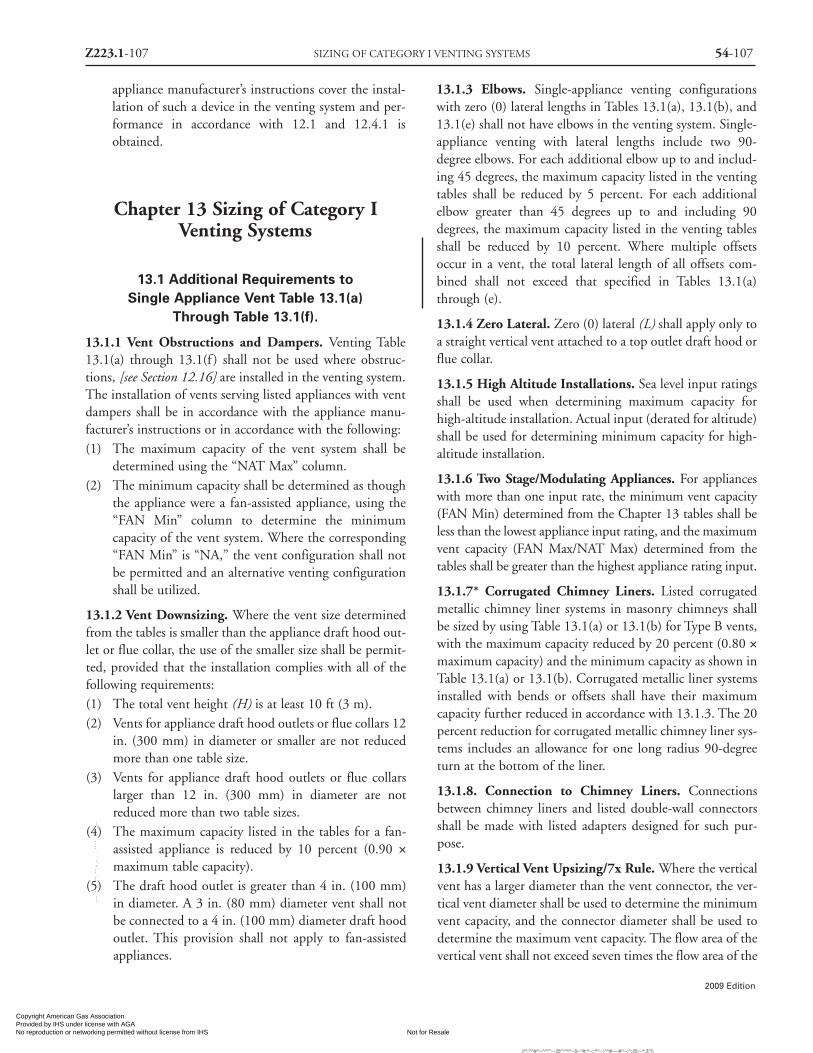
Z223.1-107 SIZING OF CATEGORY I VENTING SYSTEMS 54-107
2009 Edition
appliance manufacturer’s instructions cover the instal-lation of such a device in the venting system and per-formance in accordance with 12.1 and 12.4.1 isobtained.
Chapter 13 Sizing of Category IVenting Systems
13.1 Additional Requirements toSingle Appliance Vent Table 13.1(a)
Through Table 13.1(f).
13.1.1 Vent Obstructions and Dampers. Venting Table13.1(a) through 13.1(f ) shall not be used where obstruc-tions, [see Section 12.16] are installed in the venting system.The installation of vents serving listed appliances with ventdampers shall be in accordance with the appliance manu-facturer’s instructions or in accordance with the following:(1) The maximum capacity of the vent system shall be
determined using the “NAT Max” column.(2) The minimum capacity shall be determined as though
the appliance were a fan-assisted appliance, using the“FAN Min” column to determine the minimumcapacity of the vent system. Where the corresponding“FAN Min” is “NA,” the vent configuration shall notbe permitted and an alternative venting configurationshall be utilized.
13.1.2 Vent Downsizing. Where the vent size determinedfrom the tables is smaller than the appliance draft hood out-let or flue collar, the use of the smaller size shall be permit-ted, provided that the installation complies with all of thefollowing requirements:(1) The total vent height (H) is at least 10 ft (3 m).(2) Vents for appliance draft hood outlets or flue collars 12
in. (300 mm) in diameter or smaller are not reducedmore than one table size.
(3) Vents for appliance draft hood outlets or flue collarslarger than 12 in. (300 mm) in diameter are notreduced more than two table sizes.
(4) The maximum capacity listed in the tables for a fan-assisted appliance is reduced by 10 percent (0.90 ×maximum table capacity).
(5) The draft hood outlet is greater than 4 in. (100 mm)in diameter. A 3 in. (80 mm) diameter vent shall notbe connected to a 4 in. (100 mm) diameter draft hoodoutlet. This provision shall not apply to fan-assistedappliances.
13.1.3 Elbows. Single-appliance venting configurationswith zero (0) lateral lengths in Tables 13.1(a), 13.1(b), and13.1(e) shall not have elbows in the venting system. Single-appliance venting with lateral lengths include two 90-degree elbows. For each additional elbow up to and includ-ing 45 degrees, the maximum capacity listed in the ventingtables shall be reduced by 5 percent. For each additionalelbow greater than 45 degrees up to and including 90degrees, the maximum capacity listed in the venting tablesshall be reduced by 10 percent. Where multiple offsetsoccur in a vent, the total lateral length of all offsets com-bined shall not exceed that specified in Tables 13.1(a)through (e).
13.1.4 Zero Lateral. Zero (0) lateral (L) shall apply only toa straight vertical vent attached to a top outlet draft hood orflue collar.
13.1.5 High Altitude Installations. Sea level input ratingsshall be used when determining maximum capacity forhigh-altitude installation. Actual input (derated for altitude)shall be used for determining minimum capacity for high-altitude installation.
13.1.6 Two Stage/Modulating Appliances. For applianceswith more than one input rate, the minimum vent capacity(FAN Min) determined from the Chapter 13 tables shall beless than the lowest appliance input rating, and the maximumvent capacity (FAN Max/NAT Max) determined from thetables shall be greater than the highest appliance rating input.
13.1.7* Corrugated Chimney Liners. Listed corrugatedmetallic chimney liner systems in masonry chimneys shallbe sized by using Table 13.1(a) or 13.1(b) for Type B vents,with the maximum capacity reduced by 20 percent (0.80 ×maximum capacity) and the minimum capacity as shown inTable 13.1(a) or 13.1(b). Corrugated metallic liner systemsinstalled with bends or offsets shall have their maximumcapacity further reduced in accordance with 13.1.3. The 20percent reduction for corrugated metallic chimney liner sys-tems includes an allowance for one long radius 90-degreeturn at the bottom of the liner.
13.1.8. Connection to Chimney Liners. Connectionsbetween chimney liners and listed double-wall connectorsshall be made with listed adapters designed for such pur-pose.
13.1.9 Vertical Vent Upsizing/7x Rule. Where the verticalvent has a larger diameter than the vent connector, the ver-tical vent diameter shall be used to determine the minimumvent capacity, and the connector diameter shall be used todetermine the maximum vent capacity. The flow area of thevertical vent shall not exceed seven times the flow area of the
Copyright American Gas Association Provided by IHS under license with AGA
Not for ResaleNo reproduction or networking permitted without license from IHS
--`,,```,,,,````-`-`,,`,,`,`,,`---
//^:^^#^~^^""~:@":^*^~$~"#:*~::*^~:^^#~~#^~:^:@:~*:$"\\

54-108 NATIONAL FUEL GAS CODE Z223.1-108
2009 Edition
listed appliance categorized vent area, flue collar area, ordraft hood outlet area unless designed in accordance withapproved engineering methods.
13.1.10 Draft Hood Conversion Accessories. Draft hoodconversion accessories for use with masonry chimneys vent-ing listed Category I fan-assisted appliances shall be listedand installed in accordance with the listed accessory manu-facturer’s installation instructions.
13.1.11 Chimneys and Vent Locations. Table 13.1(a)through Table 13.1(e) shall only be used for chimneys andvents not exposed to the outdoors below the roof line. AType B vent or listed chimney lining system passingthrough an unused masonry chimney flue shall not be con-sidered to be exposed to the outdoors. A type B vent pass-ing through an unventilated enclosure or chase insulated toa value of not less than R8 shall not be considered to beexposed to the outdoors. Table 13.1(c) in combination withTable 13.1(f ) shall be used for clay-tile-lined exteriormasonry chimneys, provided all of the following require-ments are met:
(1) Vent connector is Type B double wall.
(2) Vent connector length is limited to 18 in./in. (18mm/mm) of vent connector diameter.
(3) The appliance is draft hood-equipped.
(4) The input rating is less than the maximum capacitygiven in Table 13.1(c).
(5) For a water heater, the outdoor design temperature
shall not be less than 5°F (-15°C).(6) For a space-heating appliance, the input rating is greater
than the minimum capacity given by Table 13.1(f )
13.1.12 Corrugated Vent Connector Size. Corrugatedvent connectors shall not be smaller than the listed appli-ance categorized vent diameter, flue collar diameter, or drafthood outlet diameter.
13.1.13 Vent Connector Upsizing. Vent connectors shallnot be upsized more than two sizes greater than the listedappliance categorized vent diameter, flue collar diameter, ordraft hood outlet diameter.
13.1.14 Multiple Vertical Vent Sizes. In a single run ofvent or vent connector, more than one diameter and typeshall be permitted to be used, provided that all the sizes andtypes are permitted by the tables.
13.1.15 Interpolation. Interpolation shall be permitted incalculating capacities for vent dimensions that fall betweentable entries. [See G.1.3 Example 3.]
13.1.16 Extrapolation Prohibited. Extrapolation beyondthe table entries shall not be permitted.
13.1.17 Sizing Vents Not Covered by Tables. For ventheights lower than 6 ft (1.8 m) and higher than shown in theChapter 13 tables, engineering methods shall be used to cal-culate vent capacities.
For SI units: 1 in.2 = 25.4 mm; 1 in.2 = 645 mm2; 1 ft =0.305 m; 1000 Btu/hr = 0.293 kW
Copyright American Gas Association Provided by IHS under license with AGA
Not for ResaleNo reproduction or networking permitted without license from IHS
--`,,```,,,,````-`-`,,`,,`,`,,`---
//^:^
^#^~
^^""
~:@
":^*^
~$~"
#:*~
::*^~
:^^#
~~#^
~:^:
@:~
*:$"
\\

2009 Edition
54-109 SIZING OF CATEGORY I VENTING SYSTEMS Z223.1-109
Vent Diameter — D in.3 4 5 6 7 8 9
Appliance Input Rating in Thousands of Btu per HourFAN NAT FAN NAT FAN NAT FAN NAT FAN NAT FAN NAT FAN NAT
Min Max Max Min Max Max Min Max Max Min Max Max Min Max Max Min Max Max Min Max Max
6 0 0 78 46 0 152 86 0 251 141 0 375 205 0 524 285 0 698 370 0 897 4702 13 51 36 18 97 67 27 157 105 32 232 157 44 321 217 53 425 285 63 543 3704 21 49 34 30 94 64 39 153 103 50 227 153 66 316 211 79 419 279 93 536 3626 25 46 32 36 91 61 47 149 100 59 223 149 78 310 205 93 413 273 110 530 354
8 0 0 84 50 0 165 94 0 276 155 0 415 235 0 583 320 0 780 415 0 1006 5372 12 57 40 16 109 75 25 178 120 28 263 180 42 365 247 50 483 322 60 619 4185 23 53 38 32 103 71 42 171 115 53 255 173 70 356 237 83 473 313 99 607 4078 28 49 35 39 98 66 51 164 109 64 247 165 84 347 227 99 463 303 117 596 396
10 0 0 88 53 0 175 100 0 295 166 0 447 255 0 631 345 0 847 450 0 1096 5852 12 61 42 17 118 81 23 194 129 26 289 195 40 402 273 48 533 355 57 684 4575 23 57 40 32 113 77 41 187 124 52 280 188 68 392 263 81 522 346 95 671 44610 30 51 36 41 104 70 54 176 115 67 267 175 88 376 245 104 504 330 122 651 427
15 0 0 94 58 0 191 112 0 327 187 0 502 285 0 716 390 0 970 525 0 1263 6822 11 69 48 15 136 93 20 226 150 22 339 225 38 475 316 45 633 414 53 815 5445 22 65 45 30 130 87 39 219 142 49 330 217 64 463 300 76 620 403 90 800 52910 29 59 41 40 121 82 51 206 135 64 315 208 84 445 288 99 600 386 116 777 50715 35 53 37 48 112 76 61 195 128 76 301 198 98 429 275 115 580 373 134 755 491
20 0 0 97 61 0 202 119 0 349 202 0 540 307 0 776 430 0 1057 575 0 1384 7522 10 75 51 14 149 100 18 250 166 20 377 249 33 531 346 41 711 470 50 917 6125 21 71 48 29 143 96 38 242 160 47 367 241 62 519 337 73 697 460 86 902 59910 28 64 44 38 133 89 50 229 150 62 351 228 81 499 321 95 675 443 112 877 57615 34 58 40 46 124 84 59 217 142 73 337 217 94 481 308 111 654 427 129 853 55720 48 52 35 55 116 78 69 206 134 84 322 206 107 464 295 125 634 410 145 830 537
30 0 0 100 64 0 213 128 0 374 220 0 587 336 0 853 475 0 1173 650 0 1548 8552 9 81 56 13 166 112 14 283 185 18 432 280 27 613 394 33 826 535 42 1072 7005 21 77 54 28 160 108 36 275 176 45 421 273 58 600 385 69 811 524 82 1055 68810 27 70 50 37 150 102 48 262 171 59 405 261 77 580 371 91 788 507 107 1028 66815 33 64 NA 44 141 96 57 249 163 70 389 249 90 560 357 105 765 490 124 1002 64820 56 58 NA 53 132 90 66 237 154 80 374 237 102 542 343 119 743 473 139 977 62830 NA NA NA 73 113 NA 88 214 NA 104 346 219 131 507 321 149 702 444 171 929 594
50 0 0 101 67 0 216 134 0 397 232 0 633 363 0 932 518 0 1297 708 0 1730 9522 8 86 61 11 183 122 14 320 206 15 497 314 22 715 445 26 975 615 33 1276 8135 20 82 NA 27 177 119 35 312 200 43 487 308 55 702 438 65 960 605 77 1259 79810 26 76 NA 35 168 114 45 299 190 56 471 298 73 681 426 86 935 589 101 1230 77315 59 70 NA 42 158 NA 54 287 180 66 455 288 85 662 413 100 911 572 117 1203 74720 NA NA NA 50 149 NA 63 275 169 76 440 278 97 642 401 113 888 556 131 1176 72230 NA NA NA 69 131 NA 84 250 NA 99 410 259 123 605 376 141 844 522 161 1125 670
100 0 NA NA NA 0 218 NA 0 407 NA 0 665 400 0 997 560 0 1411 770 0 1908 10402 NA NA NA 10 194 NA 12 354 NA 13 566 375 18 831 510 21 1155 700 25 1536 9355 NA NA NA 26 189 NA 33 347 NA 40 557 369 52 820 504 60 1141 692 71 1519 92610 NA NA NA 33 182 NA 43 335 NA 53 542 361 68 801 493 80 1118 679 94 1492 91015 NA NA NA 40 174 NA 50 321 NA 62 528 353 80 782 482 93 1095 666 109 1465 89520 NA NA NA 47 166 NA 59 311 NA 71 513 344 90 763 471 105 1073 653 122 1438 88030 NA NA NA NA NA NA 78 290 NA 92 483 NA 115 726 449 131 1029 627 149 1387 84950 NA NA NA NA NA NA NA NA NA 147 428 NA 180 651 405 197 944 575 217 1288 787
Height LateralH L
(ft) (ft)
Table 13.1(a) Type B Double-WallGas Vent
Number of Appliances: SingleAppliance Type: Category I
Appliance Vent Connection: Connected Directly to Vent
Copyright American Gas Association Provided by IHS under license with AGA
Not for ResaleNo reproduction or networking permitted without license from IHS
--`,,```,,,,````-`-`,,`,,`,`,,`---
//^:^^#^~^^""~:@":^*^~$~"#:*~::*^~:^^#~~#^~:^:@
:~*:$"\\

2009 Edition
Z223.1-110 NATIONAL FUEL GAS CODE 54-110
Vent Diameter — D in.10 12 14 16 18 20 22 24
Appliance Input Rating in Thousands of Btu per HourFAN NAT FAN NAT FAN NAT FAN NAT FAN NAT FAN NAT FAN NAT FAN NAT
Min Max Max Min Max Max Min Max Max Min Max Max Min Max Max Min Max Max Min Max Max Min Max Max
6 0 0 1121 570 0 1645 850 0 2267 1170 0 2983 1530 0 3802 1960 0 4721 2430 0 5737 2950 0 6853 3520
2 75 675 455 103 982 650 138 1346 890 178 1769 1170 225 2250 1480 296 2782 1850 360 3377 2220 426 4030 2670
4 110 668 445 147 975 640 191 1338 880 242 1761 1160 300 2242 1475 390 2774 1835 469 3370 2215 555 4023 2660
6 128 661 435 171 967 630 219 1330 870 276 1753 1150 341 2235 1470 437 2767 1820 523 3363 2210 618 4017 2650
8 0 0 1261 660 0 1858 970 0 2571 1320 0 3399 1740 0 4333 2220 0 5387 2750 0 6555 3360 0 7838 4010
2 71 770 515 98 1124 745 130 1543 1020 168 2030 1340 212 2584 1700 278 3196 2110 336 3882 2560 401 4634 3050
5 115 758 503 154 1110 733 199 1528 1010 251 2013 1330 311 2563 1685 398 3180 2090 476 3863 2545 562 4612 3040
8 137 746 490 180 1097 720 231 1514 1000 289 2000 1320 354 2552 1670 450 3163 2070 537 3850 2530 630 4602 3030
10 0 0 1377 720 0 2036 1060 0 2825 1450 0 3742 1925 0 4782 2450 0 5955 3050 0 7254 3710 0 8682 4450
2 68 852 560 93 1244 850 124 1713 1130 161 2256 1480 202 2868 1890 264 3556 2340 319 4322 2840 378 5153 3390
5 112 839 547 149 1229 829 192 1696 1105 243 2238 1461 300 2849 1871 382 3536 2318 458 4301 2818 540 5132 3371
10 142 817 525 187 1204 795 238 1669 1080 298 2209 1430 364 2818 1840 459 3504 2280 546 4268 2780 641 5099 3340
15 0 0 1596 840 0 2380 1240 0 3323 1720 0 4423 2270 0 5678 2900 0 7099 3620 0 8665 4410 0 10393 5300
2 63 1019 675 86 1495 985 114 2062 1350 147 2719 1770 186 3467 2260 239 4304 2800 290 5232 3410 346 6251 4080
5 105 1003 660 140 1476 967 182 2041 1327 229 2696 1748 283 3442 2235 355 4278 2777 426 5204 3385 501 6222 4057
10 135 977 635 177 1446 936 227 2009 1289 283 2659 1712 346 3402 2193 432 4234 2739 510 5159 3343 599 6175 4019
15 155 953 610 202 1418 905 257 1976 1250 318 2623 1675 385 3363 2150 479 4192 2700 564 5115 3300 665 6129 3980
20 0 0 1756 930 0 2637 1350 0 3701 1900 0 4948 2520 0 6376 3250 0 7988 4060 0 9785 4980 0 11753 6000
2 59 1150 755 81 1694 1100 107 2343 1520 139 3097 2000 175 3955 2570 220 4916 3200 269 5983 3910 321 7154 4700
5 101 1133 738 135 1674 1079 174 2320 1498 219 3071 1978 270 3926 2544 337 4885 3174 403 5950 3880 475 7119 4662
10 130 1105 710 172 1641 1045 220 2282 1460 273 3029 1940 334 3880 2500 413 4835 3130 489 5896 3830 573 7063 4600
15 150 1078 688 195 1609 1018 248 2245 1425 306 2988 1910 372 3835 2465 459 4786 3090 541 5844 3795 631 7007 4575
20 167 1052 665 217 1578 990 273 2210 1390 335 2948 1880 404 3791 2430 495 4737 3050 585 5792 3760 689 6953 4550
30 0 0 1977 1060 0 3004 1550 0 4252 2170 0 5725 2920 0 7420 3770 0 9341 4750 0 11483 5850 0 13848 7060
2 54 1351 865 74 2004 1310 98 2786 1800 127 3696 2380 159 4734 3050 199 5900 3810 241 7194 4650 285 8617 5600
5 96 1332 851 127 1981 1289 164 2759 1775 206 3666 2350 252 4701 3020 312 5863 3783 373 7155 4622 439 8574 5552
10 125 1301 829 164 1944 1254 209 2716 1733 259 3617 2300 316 4647 2970 386 5803 3739 456 7090 4574 535 8505 5471
15 143 1272 807 187 1908 1220 237 2674 1692 292 3570 2250 354 4594 2920 431 5744 3695 507 7026 4527 590 8437 5391
20 160 1243 784 207 1873 1185 260 2633 1650 319 3523 2200 384 4542 2870 467 5686 3650 548 6964 4480 639 8370 5310
30 195 1189 745 246 1807 1130 305 2555 1585 369 3433 2130 440 4442 2785 540 5574 3565 635 6842 4375 739 8239 5225
50 0 0 2231 1195 0 3441 1825 0 4934 2550 0 6711 3440 0 8774 4460 0 11129 5635 0 13767 6940 0 16694 8430
2 41 1620 1010 66 2431 1513 86 3409 2125 113 4554 2840 141 5864 3670 171 7339 4630 209 8980 5695 251 10788 6860
5 90 1600 996 118 2406 1495 151 3380 2102 191 4520 2813 234 5826 3639 283 7295 4597 336 8933 5654 394 10737 6818
10 118 1567 972 154 2366 1466 196 3332 2064 243 4464 2767 295 5763 3585 355 7224 4542 419 8855 5585 491 10652 6749
15 136 1536 948 177 2327 1437 222 3285 2026 274 4409 2721 330 5701 3534 396 7155 4511 465 8779 5546 542 10570 6710
20 151 1505 924 195 2288 1408 244 3239 1987 300 4356 2675 361 5641 3481 433 7086 4479 506 8704 5506 586 10488 6670
30 183 1446 876 232 2214 1349 287 3150 1910 347 4253 2631 412 5523 3431 494 6953 4421 577 8557 5444 672 10328 6603
100 0 0 2491 1310 0 3925 2050 0 5729 2950 0 7914 4050 0 10485 5300 0 13454 6700 0 16817 8600 0 20578 10300
2 30 1975 1170 44 3027 1820 72 4313 2550 95 5834 3500 120 7591 4600 138 9577 5800 169 11803 7200 204 14264 8800
5 82 1955 1159 107 3002 1803 136 4282 2531 172 5797 3475 208 7548 4566 245 9528 5769 293 11748 7162 341 14204 8756
10 108 1923 1142 142 2961 1775 180 4231 2500 223 5737 3434 268 7478 4509 318 9447 5717 374 11658 7100 436 14105 8683
15 126 1892 1124 163 2920 1747 206 4182 2469 252 5678 3392 304 7409 4451 358 9367 5665 418 11569 7037 487 14007 8610
20 141 1861 1107 181 2880 1719 226 4133 2438 277 5619 3351 330 7341 4394 387 9289 5613 452 11482 6975 523 13910 8537
30 170 1802 1071 215 2803 1663 265 4037 2375 319 5505 3267 378 7209 4279 446 9136 5509 514 11310 6850 592 13720 8391
50 241 1688 1000 292 2657 1550 350 3856 2250 415 5289 3100 486 6956 4050 572 8841 5300 659 10979 6600 752 13354 8100
Height LateralH L
(ft) (ft)
Table 13.1(a) Type B Double-WallGas Vent (continued)
Number of Appliances: SingleAppliance Type: Category I
Appliance Vent Connection: Connected Directly to Vent
Copyright American Gas Association Provided by IHS under license with AGA
Not for ResaleNo reproduction or networking permitted without license from IHS
--`,,```,,,,````-`-`,,`,,`,`,,`---
//^:^^#^~^^""~:@":^*^~$~"#:*~::*^~:^^#~~#^~:^:@:~*:$"\\

2009 Edition
54-111 SIZING OF CATEGORY I VENTING SYSTEMS Z223.1-111
Vent Diameter — D in.3 4 5 6 7 8 9 10 12
Appliance Input Rating in Thousands of Btu per HourFAN NAT FAN NAT FAN NAT FAN NAT FAN NAT FAN NAT FAN NAT FAN NAT FAN NAT
Min Max Max Min Max Max Min Max Max Min Max Max Min Max Max Min Max Max Min Max Max Min Max Max Min Max Max
6 0 38 77 45 59 151 85 85 249 140 126 373 204 165 522 284 211 695 369 267 894 469 371 1118 569 537 1639 849
2 39 51 36 60 96 66 85 156 104 123 231 156 159 320 213 201 423 284 251 541 368 347 673 453 498 979 648
4 NA NA 33 74 92 63 102 152 102 146 225 152 187 313 208 237 416 277 295 533 360 409 664 443 584 971 638
6 NA NA 31 83 89 60 114 147 99 163 220 148 207 307 203 263 409 271 327 526 352 449 656 433 638 962 627
8 0 37 83 50 58 164 93 83 273 154 123 412 234 161 580 319 206 777 414 258 1002 536 360 1257 658 521 1852 967
2 39 56 39 59 108 75 83 176 119 121 261 179 155 363 246 197 482 321 246 617 417 339 768 513 486 1120 743
5 NA NA 37 77 102 69 107 168 114 151 252 171 193 352 235 245 470 311 305 604 404 418 754 500 598 1104 730
8 NA NA 33 90 95 64 122 161 107 175 243 163 223 342 225 280 458 300 344 591 392 470 740 486 665 1089 715
10 0 37 87 53 57 174 99 82 293 165 120 444 254 158 628 344 202 844 449 253 1093 584 351 1373 718 507 2031 1057
2 39 61 41 59 117 80 82 193 128 119 287 194 153 400 272 193 531 354 242 681 456 332 849 559 475 1242 848
5 52 56 39 76 111 76 105 185 122 148 277 186 190 388 261 241 518 344 299 667 443 409 834 544 584 1224 825
10 NA NA 34 97 100 68 132 171 112 188 261 171 237 369 241 296 497 325 363 643 423 492 808 520 688 1194 788
15 0 36 93 57 56 190 111 80 325 186 116 499 283 153 713 388 195 966 523 244 1259 681 336 1591 838 488 2374 1237
2 38 69 47 57 136 93 80 225 149 115 337 224 148 473 314 187 631 413 232 812 543 319 1015 673 457 1491 983
5 51 63 44 75 128 86 102 216 140 144 326 217 182 459 298 231 616 400 287 795 526 392 997 657 562 1469 963
10 NA NA 39 95 116 79 128 201 131 182 308 203 228 438 284 284 592 381 349 768 501 470 966 628 664 1433 928
15 NA NA NA NA NA 72 158 186 124 220 290 192 272 418 269 334 568 367 404 742 484 540 937 601 750 1399 894
20 0 35 96 60 54 200 118 78 346 201 114 537 306 149 772 428 1901053 573 238 1379 750 326 1751 927 473 2631 1346
2 37 74 50 56 148 99 78 248 165 113 375 248 144 528 344 182 708 468 227 914 611 309 1146 754 443 1689 1098
5 50 68 47 73 140 94 100 239 158 141 363 239 178 514 334 224 692 457 279 896 596 381 1126 734 547 1665 1074
10 NA NA 41 93 129 86 125 223 146 177 344 224 222 491 316 277 666 437 339 866 570 457 1092 702 646 1626 1037
15 NA NA NA NA NA 80 155 208 136 216 325 210 264 469 301 325 640 419 393 838 549 526 1060 677 730 1587 1005
20 NA NA NA NA NA NA 186 192 126 254 306 196 309 448 285 374 616 400 448 810 526 592 1028 651 808 1550 973
30 0 34 99 63 53 211 127 76 372 219 110 584 334 144 849 472 184 1168 647 229 1542 852 312 19711056 454 2996 1545
2 37 80 56 55 164 111 76 281 183 109 429 279 139 610 392 175 823 533 219 1069 698 296 1346 863 424 1999 1308
5 49 74 52 72 157 106 98 271 173 136 417 271 171 595 382 215 806 521 269 1049 684 366 1324 846 524 1971 1283
10 NA NA NA 91 144 98 122 255 168 171 397 257 213 570 367 265 777 501 327 1017 662 440 1287 821 620 1927 1243
15 NA NA NA 115 131 NA 151 239 157 208 377 242 255 547 349 312 750 481 379 985 638 507 1251 794 702 1884 1205
20 NA NA NA NA NA NA 181 223 NA 246 357 228 298 524 333 360 723 461 433 955 615 570 1216 768 780 1841 1166
30 NA NA NA NA NA NA NA NA NA NA NA NA 389 477 305 461 670 426 541 895 574 704 1147 720 937 1759 1101
50 0 33 99 66 51 213 133 73 394 230 105 629 361 138 928 515 176 1292 704 220 1724 948 295 22231189 428 3432 1818
2 36 84 61 53 181 121 73 318 205 104 495 312 133 712 443 168 971 613 209 1273 811 280 16151007 401 2426 1509
5 48 80 NA 70 174 117 94 308 198 131 482 305 164 696 435 204 953 602 257 1252 795 347 1591 991 496 2396 1490
10 NA NA NA 89 160 NA 118 292 186 162 461 292 203 671 420 253 923 583 313 1217 765 418 1551 963 589 2347 1455
15 NA NA NA 112 148 NA 145 275 174 199 441 280 244 646 405 299 894 562 363 1183 736 481 1512 934 668 2299 1421
20 NA NA NA NA NA NA 176 257 NA 236 420 267 285 622 389 345 866 543 415 1150 708 544 1473 906 741 2251 1387
30 NA NA NA NA NA NA NA NA NA 315 376 NA 373 573 NA 442 809 502 521 1086 649 674 1399 848 892 2159 1318
100 0 NA NA NA 49 214 NA 69 403 NA 100 659 395 131 991 555 166 1404 765 207 19001033 273 24791300 395 3912 2042
2 NA NA NA 51 192 NA 70 351 NA 98 563 373 125 828 508 158 1152 698 196 1532 933 259 19701168 371 3021 1817
5 NA NA NA 67 186 NA 90 342 NA 125 551 366 156 813 501 194 1134 688 240 1511 921 322 19451153 460 2990 1796
10 NA NA NA 85 175 NA 113 324 NA 153 532 354 191 789 486 238 1104 672 293 1477 902 389 19051133 547 2938 1763
15 NA NA NA 132 162 NA 138 310 NA 188 511 343 230 764 473 281 1075 656 342 1443 884 447 18651110 618 2888 1730
20 NA NA NA NA NA NA 168 295 NA 224 487 NA 270 739 458 325 1046 639 391 1410 864 507 18251087 690 2838 1696
30 NA NA NA NA NA NA 231 264 NA 301 448 NA 355 685 NA 418 988 NA 491 1343 824 631 17471041 834 2739 1627
50 NA NA NA NA NA NA NA NA NA NA NA NA 540 584 NA 617 866 NA 711 1205 NA 895 1591 NA 1138 2547 1489
Height LateralH L
(ft) (ft)
Table 13.1(b) Type B Double-WallGas Vent
Number of Appliances: SingleAppliance Type: Category I
Appliance Vent Connection: Single Wall Metal Connector
Copyright American Gas Association Provided by IHS under license with AGA
Not for ResaleNo reproduction or networking permitted without license from IHS
--`,,```,,,,````-`-`,,`,,`,`,,`---
//^:^^#^~^^""~:@":^*^~$~"#:*~::*^~:^^#~~#^~:^:@:~*:$"\\

2009 Edition
Z223.1-112 NATIONAL FUEL GAS CODE 54-112
Type B Double-Wall Connector Diameter — D in.To be used with chimney areas within the size limits at bottom
3 4 5 6 7 8 9 10 12Appliance Input Rating in Thousands of Btu per Hour
FAN NAT FAN NAT FAN NAT FAN NAT FAN NAT FAN NAT FAN NAT FAN NAT FAN NAT
Min Max Max Min Max Max Min Max Max Min Max Max Min Max Max Min Max Max Min Max Max Min Max Max Min Max Max
6 2 NA NA 28 NA NA 52 NA NA 86 NA NA 130 NA NA 180 NA NA 247 NA NA 320 NA NA 401 NA NA 581
5 NA NA 25 NA NA 49 NA NA 82 NA NA 117 NA NA 165 NA NA 231 NA NA 298 NA NA 376 NA NA 561
8 2 NA NA 29 NA NA 55 NA NA 93 NA NA 145 NA NA 198 NA NA 266 84 590 350 100 728 446 139 1024 651
5 NA NA 26 NA NA 52 NA NA 88 NA NA 134 NA NA 183 NA NA 247 NA NA 328 149 711 423 201 1007 640
8 NA NA 24 NA NA 48 NA NA 83 NA NA 127 NA NA 175 NA NA 239 NA NA 318 173 695 410 231 990 623
10 2 NA NA 31 NA NA 61 NA NA 103 NA NA 162 NA NA 221 68 519 298 82 655 388 98 810 491 136 1144 724
5 NA NA 28 NA NA 57 NA NA 96 NA NA 148 NA NA 204 NA NA 277 124 638 365 146 791 466 196 1124 712
10 NA NA 25 NA NA 50 NA NA 87 NA NA 139 NA NA 191 NA NA 263 155 610 347 182 762 444 240 1093 668
15 2 NA NA 35 NA NA 67 NA NA 114 NA NA 179 53 475 250 64 613 336 77 779 441 92 968 562 127 1376 841
5 NA NA 35 NA NA 62 NA NA 107 NA NA 164 NA NA 231 99 594 313 118 759 416 139 946 533 186 1352 828
10 NA NA 28 NA NA 55 NA NA 97 NA NA 153 NA NA 216 126 565 296 148 727 394 173 912 567 229 1315 777
15 NA NA NA NA NA 48 NA NA 89 NA NA 141 NA NA 201 NA NA 281 171 698 375 198 880 485 259 1280 742
20 2 NA NA 38 NA NA 74 NA NA 124 NA NA 201 51 522 274 61 678 375 73 867 491 87 1083 627 121 1548 953
5 NA NA 36 NA NA 68 NA NA 116 NA NA 184 80 503 254 95 658 350 113 845 463 133 1059 597 179 1523 933
10 NA NA NA NA NA 60 NA NA 107 NA NA 172 NA NA 237 122 627 332 143 811 440 167 1022 566 221 1482 879
15 NA NA NA NA NA NA NA NA 97 NA NA 159 NA NA 220 NA NA 314 165 780 418 191 987 541 251 1443 840
20 NA NA NA NA NA NA NA NA 83 NA NA 148 NA NA 206 NA NA 296 186 750 397 214 955 513 277 1406 807
30 2 NA NA 41 NA NA 82 NA NA 137 NA NA 216 47 581 303 57 762 421 68 985 558 81 1240 717 111 1793 1112
5 NA NA NA NA NA 76 NA NA 128 NA NA 198 75 561 281 90 741 393 106 962 526 125 1216 683 169 1766 1094
10 NA NA NA NA NA 67 NA NA 115 NA NA 184 NA NA 263 115 709 373 135 927 500 158 1176 648 210 1721 1025
15 NA NA NA NA NA NA NA NA 107 NA NA 171 NA NA 243 NA NA 353 156 893 476 181 1139 621 239 1679 981
20 NA NA NA NA NA NA NA NA 91 NA NA 159 NA NA 227 NA NA 332 176 860 450 203 1103 592 264 1638 940
30 NA NA NA NA NA NA NA NA NA NA NA NA NA NA 188 NA NA 288 NA NA 416 249 1035 555 318 1560 877
50 2 NA NA NA NA NA 92 NA NA 161 NA NA 251 NA NA 351 51 840 477 61 1106 633 72 1413 812 99 2080 1243
5 NA NA NA NA NA NA NA NA 151 NA NA 230 NA NA 323 83 819 445 98 1083 596 116 1387 774 155 2052 1225
10 NA NA NA NA NA NA NA NA 138 NA NA 215 NA NA 304 NA NA 424 126 1047 567 147 1347 733 195 2006 1147
15 NA NA NA NA NA NA NA NA 127 NA NA 199 NA NA 282 NA NA 400 146 1010 539 170 1307 702 222 1961 1099
20 NA NA NA NA NA NA NA NA NA NA NA 185 NA NA 264 NA NA 376 165 977 511 190 1269 669 246 1916 1050
30 NA NA NA NA NA NA NA NA NA NA NA NA NA NA NA NA NA 327 NA NA 468 233 1196 623 295 1832 984MinimumInternalArea of 12 19 28 38 50 63 78 95 132ChimneySquareInches.
MaximumInternalArea ofChimneySquareInches
Height LateralH L
(ft) (ft)
Table 13.1(c) Masonry ChimneyNumber of Appliances: Single
Appliance Type: Category IAppliance Vent Connection: Type B Double Wall Connector
Seven times the listed appliance categorized vent area, flue collar area, or draft hood outlet areas.
Copyright American Gas Association Provided by IHS under license with AGA
Not for ResaleNo reproduction or networking permitted without license from IHS
--`,,```,,,,````-`-`,,`,,`,`,,`---
//^:^^#^~^^""~:@":^*^~$~"#:*~::*^~:^^#~~#^~:^:@:~*:$"\\

2009 Edition
54-113 SIZING OF CATEGORY I VENTING SYSTEMS Z223.1-113
Single-Wall Metal Connector Diameter — D in.To be used with chimney areas within the size limits at bottom
3 4 5 6 7 8 9 10 12
Appliance Input Rating in Thousands of Btu per HourFAN NAT FAN NAT FAN NAT FAN NAT FAN NAT FAN NAT FAN NAT FAN NAT FAN NAT
Min Max Max Min Max Max Min Max Max Min Max Max Min Max Max Min Max Max Min Max Max Min Max Max Min Max Max
6 2 NA NA 28 NA NA 52 NA NA 86 NA NA 130 NA NA 180 NA NA 247 NA NA 319 NA NA 400 NA NA 580
5 NA NA 25 NA NA 48 NA NA 81 NA NA 116 NA NA 164 NA NA 230 NA NA 297 NA NA 375 NA NA 560
8 2 NA NA 29 NA NA 55 NA NA 93 NA NA 145 NA NA 197 NA NA 265 NA NA 349 382 725 445 549 1021 650
5 NA NA 26 NA NA 51 NA NA 87 NA NA 133 NA NA 182 NA NA 246 NA NA 327 NA NA 422 673 1003 638
8 NA NA 23 NA NA 47 NA NA 82 NA NA 126 NA NA 174 NA NA 237 NA NA 317 NA NA 408 747 985 621
10 2 NA NA 31 NA NA 61 NA NA 102 NA NA 161 NA NA 220 216 518 297 271 654 387 373 808 490 536 1142 722
5 NA NA 28 NA NA 56 NA NA 95 NA NA 147 NA NA 203 NA NA 276 334 635 364 459 789 465 657 1121 710
10 NA NA 24 NA NA 49 NA NA 86 NA NA 137 NA NA 189 NA NA 261 NA NA 345 547 758 441 771 1088 665
15 2 NA NA 35 NA NA 67 NA NA 113 NA NA 178 166 473 249 211 611 335 264 776 440 362 965 560 520 1373 840
5 NA NA 32 NA NA 61 NA NA 106 NA NA 163 NA NA 230 261 591 312 325 755 414 444 942 531 637 1348 825
10 NA NA 27 NA NA 54 NA NA 96 NA NA 151 NA NA 214 NA NA 294 392 722 392 531 907 504 749 1309 774
15 NA NA NA NA NA 46 NA NA 87 NA NA 138 NA NA 198 NA NA 278 452 692 372 606 873 481 841 1272 738
20 2 NA NA 38 NA NA 73 NA NA 123 NA NA 200 163 520 273 206 675 374 258 864 490 252 1079 625 508 1544 950
5 NA NA 35 NA NA 67 NA NA 115 NA NA 183 NA NA 252 255 655 348 317 842 461 433 1055 594 623 1518 930
10 NA NA NA NA NA 59 NA NA 105 NA NA 170 NA NA 235 312 622 330 382 806 437 517 1016 562 733 1475 875
15 NA NA NA NA NA NA NA NA 95 NA NA 156 NA NA 217 NA NA 311 442 773 414 591 979 539 823 1434 835
20 NA NA NA NA NA NA NA NA 80 NA NA 144 NA NA 202 NA NA 292 NA NA 392 663 944 510 911 1394 800
30 2 NA NA 41 NA NA 81 NA NA 136 NA NA 215 158 578 302 200 759 420 249 982 556 340 1237 715 489 1789 1110
5 NA NA NA NA NA 75 NA NA 127 NA NA 196 NA NA 279 245 737 391 306 958 524 417 1210 680 600 1760 1090
10 NA NA NA NA NA 66 NA NA 113 NA NA 182 NA NA 260 300 703 370 370 920 496 500 1168 644 708 1713 1020
15 NA NA NA NA NA NA NA NA 105 NA NA 168 NA NA 240 NA NA 349 428 884 471 572 1128 615 798 1668 975
20 NA NA NA NA NA NA NA NA 88 NA NA 155 NA NA 223 NA NA 327 NA NA 445 643 1089 585 883 1624 932
30 NA NA NA NA NA NA NA NA NA NA NA NA NA NA 182 NA NA 281 NA NA 408 NA NA 544 1055 1539 865
50 2 NA NA NA NA NA 91 NA NA 160 NA NA 250 NA NA 350 191 837 475 238 1103 631 323 1408 810 463 2076 1240
5 NA NA NA NA NA NA NA NA 149 NA NA 228 NA NA 321 NA NA 442 293 1078 593 398 1381 770 571 2044 1220
10 NA NA NA NA NA NA NA NA 136 NA NA 212 NA NA 301 NA NA 420 355 1038 562 447 1337 728 674 1994 1140
15 NA NA NA NA NA NA NA NA 124 NA NA 195 NA NA 278 NA NA 395 NA NA 533 546 1294 695 761 1945 1090
20 NA NA NA NA NA NA NA NA NA NA NA 180 NA NA 258 NA NA 370 NA NA 504 616 1251 660 844 1898 1040
30 NA NA NA NA NA NA NA NA NA NA NA NA NA NA NA NA NA 318 NA NA 458 NA NA 610 1009 1805 970
MinimumInternalArea of 12 19 28 38 50 63 78 95 132ChimneySquareInches
MaximumInternalArea ofChimneySquareInches
Height LateralH L
(ft) (ft)
Table 13.1(d) Masonry ChimneyNumber of Appliances: Single
Appliance Type: Category IAppliance Vent Connection: Single Wall Metal Connector
Seven times the listed appliance categorized vent area, flue collar area, or draft hood outlet areas.
Copyright American Gas Association Provided by IHS under license with AGA
Not for ResaleNo reproduction or networking permitted without license from IHS
--`,,```,,,,````-`-`,,`,,`,`,,`---
//^:^^#^~^^""~:@":^*^~$~"#:*~::*^~:^^#~~#^~:^:@
:~*:$"\\

2009 Edition
Z223.1-114 NATIONAL FUEL GAS CODE 54-114
Vent Diameter — D in.
3 4 5 6 7 8 10 12
Appliance Input Rating in Thousands of Btu per Hour
6 0 39 70 116 170 232 312 500 7502 31 55 94 141 194 260 415 6205 28 51 88 128 177 242 390 600
8 0 42 76 126 185 252 340 542 8152 32 61 102 154 210 284 451 6805 29 56 95 141 194 264 430 648
10 24 49 86 131 180 250 406 62510 0 45 84 138 202 279 372 606 912
2 35 67 111 168 233 311 505 7605 32 61 104 153 215 289 480 724
10 27 54 94 143 200 274 455 70015 NA 46 84 130 186 258 432 666
15 0 49 91 151 223 312 420 684 10402 39 72 122 186 260 350 570 8655 35 67 110 170 240 325 540 825
10 30 58 103 158 223 308 514 79515 NA 50 93 144 207 291 488 76020 NA NA 82 132 195 273 466 726
20 0 53 101 163 252 342 470 770 11902 42 80 136 210 286 392 641 9905 38 74 123 192 264 364 610 945
10 32 65 115 178 246 345 571 91015 NA 55 104 163 228 326 550 87020 NA NA 91 149 214 306 525 832
30 0 56 108 183 276 384 529 878 13702 44 84 148 230 320 441 730 11405 NA 78 137 210 296 410 694 1080
10 NA 68 125 196 274 388 656 105015 NA NA 113 177 258 366 625 100020 NA NA 99 163 240 344 596 96030 NA NA NA NA 192 295 540 890
50 0 NA 120 210 310 443 590 980 15502 NA 95 171 260 370 492 820 12905 NA NA 159 234 342 474 780 1230
10 NA NA 146 221 318 456 730 119015 NA NA NA 200 292 407 705 113020 NA NA NA 185 276 384 670 108030 NA NA NA NA 222 330 605 1010
Height LateralH L
(ft) (ft)
Table 13.1(e) Single Wall MetalPipe or Type BAsbestos CementVent
Number of Appliances: SingleAppliance Type: Draft-Hood-Equipped
Appliance Vent Connection: Connected Directly to Pipe or Vent
Copyright American Gas Association Provided by IHS under license with AGA
Not for ResaleNo reproduction or networking permitted without license from IHS
--`,,```,,,,````-`-`,,`,,`,`,,`---
//^:^
^#^~
^^""
~:@
":^*^
~$~"
#:*~
::*^~
:^^#
~~#^
~:^:
@:~
*:$"
\\

Z223.1-115 SIZING OF CATEGORY I VENTING SYSTEMS 54-115
2009 Edition
Table 13.1(f) Exterior MasonryChimney
Special Use: Minimum Allowable Input Rating of Space-Heating Appliance in Thousandsof Btu per Hour
Number of Appliances: Single
Appliance Type: NATAppliance Vent Connection: Type B Double Wall
Connector
Internal Area of Chimney (in.2)12 19 28 38 50 63 78 113
Local 99% Winter Design Temperature: 37°F or greater
6 0 0 0 0 0 0 0 08 0 0 0 0 0 0 0 010 0 0 0 0 0 0 0 015 NA 0 0 0 0 0 0 020 NA NA 123 190 249 184 0 030 NA NA NA NA NA 393 334 050 NA NA NA NA NA NA NA 579
Local 99% winter design temperature: 27°F to 36°F
6 0 0 68 116 156 180 212 2668 0 0 82 127 167 187 214 26310 0 51 97 141 183 201 225 26515 NA NA NA NA 233 253 274 30520 NA NA NA NA NA 307 330 36230 NA NA NA NA NA 419 445 48550 NA NA NA NA NA NA NA 763
Local 99% winter design temperature: 17°F to 26°F
6 NA NA NA NA NA 215 259 3498 NA NA NA NA 197 226 264 35210 NA NA NA NA 214 245 278 35815 NA NA NA NA NA 296 331 39820 NA NA NA NA NA 352 387 45730 NA NA NA NA NA NA 507 58150 NA NA NA NA NA NA NA NA
Local 99% winter design temperature: 5°F to 16°F
6 NA NA NA NA NA NA NA 4168 NA NA NA NA NA NA 312 42310 NA NA NA NA NA 289 331 43015 NA NA NA NA NA NA 393 48520 NA NA NA NA NA NA 450 54730 NA NA NA NA NA NA NA 68250 NA NA NA NA NA NA NA 972
Local 99% winter design temperature: -10°F to 4°F
6 NA NA NA NA NA NA NA 4848 NA NA NA NA NA NA NA 49410 NA NA NA NA NA NA NA 51315 NA NA NA NA NA NA NA 58620 NA NA NA NA NA NA NA 65030 NA NA NA NA NA NA NA 80550 NA NA NA NA NA NA NA 1003
Local 99% winter design temperature: -11°F or LowerNot recommended for any vent configurations
See Figure G.2.4 for a map showing local 99 percent winter designtemperatures in the United States.
13.2 Additional Requirements toMultiple Appliance Vent Table 13.2(a)
Through Table 13.2(i).
13.2.1 Vent Obstructions and Dampers. Venting Table13.2(a) through 13.2(i) shall not be used where obstruc-tions [see Section 12.16] are installed in the venting system.The installation of vents serving listed appliances with ventdampers shall be in accordance with the appliance manu-facturer’s instructions, or in accordance with the following:(1) The maximum capacity of the vent connector shall be
determined using the NAT Max column.(2) The maximum capacity of the vertical vent or chimney
shall be determined using the FAN+NAT column whenthe second appliance is a fan-assisted appliance, or theNAT+NAT column when the second appliance isequipped with a draft hood.
(3) The minimum capacity shall be determined as if theappliance were a fan-assisted appliance as follows:(a) The minimum capacity of the vent connector shall be
determined using the FAN Min column.(b) The FAN+FAN column shall be used when the sec-
ond appliance is a fan-assisted appliance, and theFAN+NAT column shall be used when the secondappliance is equipped with a draft hood, to determinewhether the vertical vent or chimney configuration isnot permitted (NA). Where the vent configuration isNA, the vent configuration shall not be permitted andan alternative venting configuration shall be utilized.
13.2.2 Vent Connector Maximum Length. The maximumvent connector horizontal length shall be 18 in./in. (18mm/mm) of connector diameter as shown in Table 13.2.2:
Table 13.2.2 Vent Connector Maximum Length
Connector Connector Connector ConnectorDiameter Horizontal Diameter HorizontalMaximum Length Maximum Length
(in.) (ft) (in.) (ft)3 4 1⁄2 12 184 6 14 215 7 1⁄2 16 246 9 18 277 10 1⁄2 20 308 12 22 339 13 1⁄2 24 3610 15
For SI units: 1 in. = 25.4 mm; 1 ft = 0.305 m.
13.2.3 Vent Connector Exceeding Maximum Length.The vent connector shall be routed to the vent utilizing theshortest possible route. Connectors with longer horizontallengths than those listed in Table 13.2.2 are permitted
VentHeightH (ft)
Copyright American Gas Association Provided by IHS under license with AGA
Not for ResaleNo reproduction or networking permitted without license from IHS
--`,,```,,,,````-`-`,,`,,`,`,,`---
//^:^
^#^~
^^""
~:@
":^*^
~$~"
#:*~
::*^~
:^^#
~~#^
~:^:
@:~
*:$"
\\
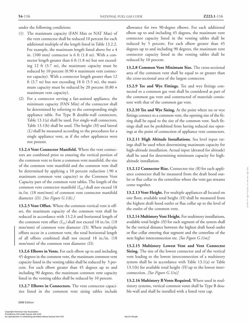
54-116 NATIONAL FUEL GAS CODE Z223.1-116
2009 Edition
under the following conditions:(1) The maximum capacity (FAN Max or NAT Max) of
the vent connector shall be reduced 10 percent for eachadditional multiple of the length listed in Table 13.2.2.For example, the maximum length listed above for a 4in. (100 mm) connector is 6 ft (1.8 m). With a con-nector length greater than 6 ft (1.8 m) but not exceed-ing 12 ft (3.7 m), the maximum capacity must bereduced by 10 percent (0.90 × maximum vent connec-tor capacity). With a connector length greater than 12ft (3.7 m) but not exceeding 18 ft (5.5 m), the maxi-mum capacity must be reduced by 20 percent (0.80 ×maximum vent capacity).
(2) For a connector serving a fan-assisted appliance, theminimum capacity (FAN Min) of the connector shallbe determined by referring to the corresponding singleappliance table. For Type B double-wall connectors,Table 13.1(a) shall be used. For single-wall connectors,Table 13.1(b) shall be used. The height (H) and lateral(L) shall be measured according to the procedures for asingle appliance vent, as if the other appliances werenot present.
13.2.4 Vent Connector Manifold. Where the vent connec-tors are combined prior to entering the vertical portion ofthe common vent to form a common vent manifold, the sizeof the common vent manifold and the common vent shallbe determined by applying a 10 percent reduction (.90 ×maximum common vent capacity) to the Common VentCapacity part of the common vent tables. The length of thecommon vent connector manifold (LM) shall not exceed 18in./in. (18 mm/mm) of common vent connector manifolddiameter (D). [See Figure G.1(k).]
13.2.5 Vent Offset. Where the common vertical vent is off-set, the maximum capacity of the common vent shall bereduced in accordance with 13.2.6 and horizontal length ofthe common vent offset (LO) shall not exceed 18 in./in. (18mm/mm) of common vent diameter (D). Where multipleoffsets occur in a common vent, the total horizontal lengthof all offsets combined shall not exceed 18 in./in. (18mm/mm) of the common vent diameter (D).
13.2.6 Elbows in Vents. For each elbow up to and including45 degrees in the common vent, the maximum common ventcapacity listed in the venting tables shall be reduced by 5 per-cent. For each elbow greater than 45 degrees up to andincluding 90 degrees, the maximum common vent capacitylisted in the venting tables shall be reduced by 10 percent.
13.2.7 Elbows in Connectors. The vent connector capaci-ties listed in the common vent sizing tables include
allowance for two 90-degree elbows. For each additionalelbow up to and including 45 degrees, the maximum ventconnector capacity listed in the venting tables shall bereduced by 5 percent. For each elbow greater than 45degrees up to and including 90 degrees, the maximum ventconnector capacity listed in the venting tables shall bereduced by 10 percent.
13.2.8 Common Vent Minimum Size. The cross-sectionalarea of the common vent shall be equal to or greater thanthe cross-sectional area of the largest connector.
13.2.9 Tee and Wye Fittings. Tee and wye fittings con-nected to a common gas vent shall be considered as part ofthe common gas vent and constructed of materials consis-tent with that of the common gas vent.
13.2.10 Tee and Wye Sizing. At the point where tee or wyefittings connect to a common vent, the opening size of the fit-ting shall be equal to the size of the common vent. Such fit-tings shall not be prohibited from having reduced size open-ings at the point of connection of appliance vent connectors.
13.2.11 High Altitude Installations. Sea level input rat-ings shall be used when determining maximum capacity forhigh-altitude installation. Actual input (derated for altitude)shall be used for determining minimum capacity for high-altitude installation.
13.2.12 Connector Rise. Connector rise (R) for each appli-ance connector shall be measured from the draft hood out-let or flue collar to the centerline where the vent gas streamscome together.
13.2.13 Vent Height. For multiple appliances all located onone floor, available total height (H) shall be measured fromthe highest draft hood outlet or flue collar up to the level ofthe outlet of the common vent.
13.2.14 Multistory Vent Height. For multistory installations,available total height (H) for each segment of the system shallbe the vertical distance between the highest draft hood outletor flue collar entering that segment and the centerline of thenext higher interconnection tee. [See Figure G.1(m)]
13.2.15 Multistory Lowest Vent and Vent ConnectorSizing. The size of the lowest connector and of the verticalvent leading to the lowest interconnection of a multistorysystem shall be in accordance with Table 13.1(a) or Table13.1(b) for available total height (H) up to the lowest inter-connection. [See Figure G.1(n)]
13.2.16 Multistory B Vents Required. Where used in mul-tistory systems, vertical common vents shall be Type B dou-ble-wall and shall be installed with a listed vent cap.
Copyright American Gas Association Provided by IHS under license with AGA
Not for ResaleNo reproduction or networking permitted without license from IHS
--`,,```,,,,````-`-`,,`,,`,`,,`---
//^:^
^#^~
^^""
~:@
":^*^
~$~"
#:*~
::*^~
:^^#
~~#^
~:^:
@:~
*:$"
\\

13.2.17 Multistory Vent Offsets and Capacity. Offsets inmultistory common vent systems shall be limited to a singleoffset in each system, and systems with an offset shall com-ply with all of the following:(1) The offset angle shall not exceed 45 degrees from
vertical.(2) The horizontal length of the offset shall not exceed 18
in./in. (18 mm/mm) of common vent diameter of thesegment in which the offset is located.
(3) For the segment of the common vertical vent contain-ing the offset, the common vent capacity listed in thecommon venting tables shall be reduced by 20 percent(0.80 × maximum common vent capacity).
(4) A multistory common vent shall not be reduced in sizeabove the offset.
13.2.18 Vertical Vent Size Limitation. Where two or moreappliances are connected to a vertical vent or chimney, theflow area of the largest section of vertical vent or chimneyshall not exceed seven times the smallest listed appliancecategorized vent areas, flue collar area, or draft hood outletarea unless designed in accordance with approved engineer-ing methods.
13.2.19 Two Stage/Modulating Appliances. For appli-ances with more than one input rate, the minimum ventconnector capacity (FAN Min) determined from the tablesshall be less than the lowest appliance input rating, and themaximum vent connector capacity (FAN Max or NATMax) determined from the tables shall be greater than thehighest appliance input rating.
13.2.20* Corrugated Chimney Liners. Listed, corrugatedmetallic chimney liner systems in masonry chimneys shallbe sized by using Table 13.2(a) or Table 13.2(b) for Type Bvents, with the maximum capacity reduced by 20 percent(0.80 × maximum capacity) and the minimum capacity asshown in Table 13.2(a) or Table 13.2(b). Corrugated metal-lic liner systems installed with bends or offsets shall havetheir maximum capacity further reduced in accordance with13.2.5 and 13.2.6. The 20 percent reduction for corrugatedmetallic chimney liner systems includes an allowance forone long radius 90-degree turn at the bottom of the liner.
13.2.21 Connections to Chimney Liners. Where double-wall connectors are required, tee and wye fittings used toconnect to the common vent chimney liner shall be listeddouble-wall fittings. Connections between chimney linersand listed double-wall fittings shall be made with listedadapter fittings designed for such purpose.
13.2.22 Chimneys and Vent Locations. Table 13.2(a)through Table 13.2(e) shall only be used for chimneys and
vents not exposed to the outdoors below the roof line. AType B vent or listed chimney lining system passing throughan unused masonry chimney flue shall not be considered tobe exposed to the outdoors. A type B vent passing throughan unventilated enclosure or chase insulated to a value of notless than R8 shall not be considered to be exposed to the out-doors. Table 13.2(f ), Table 13.2(g), Table 13.2(h), and Table13.2(i) shall be used for clay-tile-lined exterior masonrychimneys, provided all of the following conditions are met:(1) Vent connector is Type B double-wall.(2) At least one appliance is draft hood-equipped.(3) The combined appliance input rating is less than the
maximum capacity given by Table 13.2(f ) (forNAT+NAT) or Table 13.2(h) (for FAN+NAT).
(4) The input rating of each space-heating appliance isgreater than the minimum input rating given by Table13.2(g) (for NAT+NAT) or Table 13.2(i) (forFAN+NAT).
(5) The vent connector sizing is in accordance with Table13.2(c)
13.2.23 Draft Hood Conversion Accessories. Draft hoodconversion accessories for use with masonry chimneys vent-ing listed Category I fan-assisted appliances shall be listedand installed in accordance with the listed accessory manu-facturer’s installation instructions.
13.2.24 Vent Connector Sizing. Vent connectors shall notbe increased more than two sizes greater than the listedappliance categorized vent diameter, flue collar diameter, ordraft hood outlet diameter. Vent connectors for draft hood-equipped appliances shall not be smaller than the drafthood outlet diameter. Where a vent connector size(s) deter-mined from the tables for a fan-assisted appliance(s) issmaller than the flue collar diameter, the use of the smallersize(s) shall be permitted, provided that the installationcomplies with all of the following conditions:(1) Vent connectors for fan-assisted appliance flue collars
12 in. (300 mm) in diameter or smaller are notreduced by more than one table size [e.g., 12 in. to 10in. (300 mm to 250 mm) is a one-size reduction], andthose larger than 12 in. (300 mm) in diameter are notreduced more than two table sizes [e.g., 24 in. to 20 in.(610 mm to 510 mm) is a two-size reduction].
(2) The fan-assisted appliance(s) is common vented with adraft hood-equipped appliance(s).
(3) The vent connector has a smooth interior wall.
13.2.25 Multiple Vent and Connector Sizes. All combi-nations of pipe sizes, single-wall, and double-wall metalpipe shall be allowed within any connector run(s) or within
Z223.1-117 SIZING OF CATEGORY I VENTING SYSTEMS 54-117
2009 Edition
Copyright American Gas Association Provided by IHS under license with AGA
Not for ResaleNo reproduction or networking permitted without license from IHS
--`,,```,,,,````-`-`,,`,,`,`,,`---
//^:^
^#^~
^^""
~:@
":^*^
~$~"
#:*~
::*^~
:^^#
~~#^
~:^:
@:~
*:$"
\\

2009 Edition
Z223.1-118 NATIONAL FUEL GAS CODE 54-118
the common vent, provided ALL of the appropriate tablespermit ALL of the desired sizes and types of pipe, as if theywere used for the entire length of the subject connector orvent. Where single-wall and Type B double-wall metal pipesare used for vent connectors within the same venting sys-tem, the common vent shall be sized using Table 13.2(b) orTable 13.2(d) as appropriate.
13.2.26 Multiple Vent and Connector Sizes Permitted.Where a Chapter 13 table permits more than one diameterof pipe to be used for a connector or vent, all the permittedsizes shall be permitted to be used.
13.2.27 Interpolation. Interpolation shall be permitted incalculating capacities for vent dimensions that fall betweentable entries. [See G.1.3 Example 3.]
13.2.28 Extrapolation. Extrapolation beyond the tableentries shall not be permitted.
13.2.29 Sizing of Vents Not Covered by Tables. For ventheights lower than 6 ft and higher than shown in the Chapter13 tables, engineering methods shall be used to calculate ventcapacities.
For SI units: 1 in.2 = 25.4 mm; 1 in.2 = 645 mm2; 1 ft =0.305 m; 1000 Btu/hr = 0.293 kW
Copyright American Gas Association Provided by IHS under license with AGA
Not for ResaleNo reproduction or networking permitted without license from IHS
--`,,```,,,,````-`-`,,`,,`,`,,`---
//^:^
^#^~
^^""
~:@
":^*^
~$~"
#:*~
::*^~
:^^#
~~#^
~:^:
@:~
*:$"
\\

2009 Edition
54-119 SIZING OF CATEGORY I VENTING SYSTEMS Z223.1-119
Vent CONNECTOR Capacity
Type B Double-Wall Connector Diameter — D in.3 4 5 6 7 8 9 10
Appliance Input Rating Limits in Thousands of Btu per HourFAN NAT FAN NAT FAN NAT FAN NAT FAN NAT FAN NAT FAN NAT FAN NAT
Min Max Max Min Max Max Min Max Max Min Max Max Min Max Max Min Max Max Min Max Max Min Max Max6 1 22 37 26 35 66 46 46 106 72 58 164 104 77 225 142 92 296 185 109 376 237 128 466 289
2 23 41 31 37 75 55 48 121 86 60 183 124 79 253 168 95 333 220 112 424 282 131 526 3453 24 44 35 38 81 62 49 132 96 62 199 139 82 275 189 97 363 248 114 463 317 134 575 386
8 1 22 40 27 35 72 48 49 114 76 64 176 109 84 243 148 100 320 194 118 408 248 138 507 3032 23 44 32 36 80 57 51 128 90 66 195 129 86 269 175 103 356 230 121 454 294 141 564 3583 24 47 36 37 87 64 53 139 101 67 210 145 88 290 198 105 384 258 123 492 330 143 612 402
10 1 22 43 28 34 78 50 49 123 78 65 189 113 89 257 154 106 341 200 125 436 257 146 542 3142 23 47 33 36 86 59 51 136 93 67 206 134 91 282 182 109 374 238 128 479 305 149 596 3723 24 50 37 37 92 67 52 146 104 69 220 150 94 303 205 111 402 268 131 515 342 152 642 417
15 1 21 50 30 33 89 53 47 142 83 64 220 120 88 298 163 110 389 214 134 493 273 162 609 3332 22 53 35 35 96 63 49 153 99 66 235 142 91 320 193 112 419 253 137 532 323 165 658 3943 24 55 40 36 102 71 51 163 111 68 248 160 93 339 218 115 445 286 140 565 365 167 700 444
20 1 21 54 31 33 99 56 46 157 87 62 246 125 86 334 171 107 436 224 131 552 285 158 681 3472 22 57 37 34 105 66 48 167 104 64 259 149 89 354 202 110 463 265 134 587 339 161 725 4143 23 60 42 35 110 74 50 176 116 66 271 168 91 371 228 113 486 300 137 618 383 164 764 466
30 1 20 62 33 31 113 59 45 181 93 60 288 134 83 391 182 103 512 238 125 649 305 151 802 3722 21 64 39 33 118 70 47 190 110 62 299 158 85 408 215 105 535 282 129 679 360 155 840 4393 22 66 44 34 123 79 48 198 124 64 309 178 88 423 242 108 555 317 132 706 405 158 874 494
50 1 19 71 36 30 133 64 43 216 101 57 349 145 78 477 197 97 627 257 120 797 330 144 984 4032 21 73 43 32 137 76 45 223 119 59 358 172 81 490 234 100 645 306 123 820 392 148 1014 4783 22 75 48 33 141 86 46 229 134 61 366 194 83 502 263 103 661 343 126 842 441 151 1043 538
100 1 18 82 37 28 158 66 40 262 104 53 442 150 73 611 204 91 810 266 112 1038 341 135 1285 4172 19 83 44 30 161 79 42 267 123 55 447 178 75 619 242 94 822 316 115 1054 405 139 1306 4943 20 84 50 31 163 89 44 272 138 57 452 200 78 627 272 97 834 355 118 1069 455 142 1327 555
Common VENT Capacity
Type B Double-Wall Common Vent Diameter — D in.4 5 6 7 8 9 10
Combined Appliance Input Rating in Thousands of Btu per HourFAN FAN NAT FAN FAN NAT FAN FAN NAT FAN FAN NAT FAN FAN NAT FAN FAN NAT FAN FAN NAT+FAN +NAT +NAT +FAN +NAT +NAT +FAN +NAT +NAT +FAN +NAT +NAT +FAN +NAT +NAT +FAN +NAT +NAT +FAN +NAT +NAT
6 92 81 65 140 116 103 204 161 147 309 248 200 404 314 260 547 434 335 672 520 410
8 101 90 73 155 129 114 224 178 163 339 275 223 444 348 290 602 480 378 740 577 465
10 110 97 79 169 141 124 243 194 178 367 299 242 477 377 315 649 522 405 800 627 495
15 125 112 91 195 164 144 283 228 206 427 352 280 556 444 365 753 612 465 924 733 565
20 136 123 102 215 183 160 314 255 229 475 394 310 621 499 405 842 688 523 1035 826 640
30 152 138 118 244 210 185 361 297 266 547 459 360 720 585 470 979 808 605 1209 975 740
50 167 153 134 279 244 214 421 353 310 641 547 423 854 706 550 1164 977 705 1451 1188 860
100 175 163 NA 311 277 NA 489 421 NA 751 658 479 1025 873 625 1408 1215 800 1784 1502 975
VentHeight
H(ft)
Table 13.2(a) Type BDouble-Wall Vent
Number of Appliances: Two or MoreAppliance Type: Category I
Appliance Vent Connection: Type B Double Wall Connector
ConnectorHeight Rise
H R(ft) (ft)
Copyright American Gas Association Provided by IHS under license with AGA
Not for ResaleNo reproduction or networking permitted without license from IHS
--`,,```,,,,````-`-`,,`,,`,`,,`---
//^:^^#^~^^""~:@":^*^~$~"#:*~::*^~:^^#~~#^~:^:@:~*:$"\\
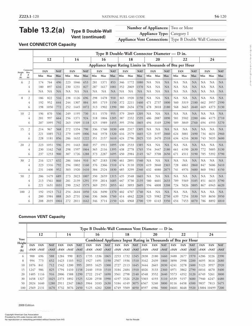
2009 Edition
Z223.1-120 NATIONAL FUEL GAS CODE 54-120
Vent CONNECTOR Capacity
Type B Double-Wall Connector Diameter — D in.12 14 16 18 20 22 24
Appliance Input Rating Limits in Thousands of Btu per HourFAN NAT FAN NAT FAN NAT FAN NAT FAN NAT FAN NAT FAN NAT
Min Max Max Min Max Max Min Max Max Min Max Max Min Max Max Min Max Max Min Max Max
6 2 174 764 496 223 1046 653 281 1371 853 346 1772 1080 NA NA NA NA NA NA NA NA NA4 180 897 616 230 1231 827 287 1617 1081 352 2069 1370 NA NA NA NA NA NA NA NA NA6 NA NA NA NA NA NA NA NA NA NA NA NA NA NA NA NA NA NA NA NA NA
8 2 186 822 516 238 1126 696 298 1478 910 365 1920 1150 NA NA NA NA NA NA NA NA NA4 192 952 644 244 1307 884 305 1719 1150 372 2211 1460 471 2737 1800 560 3319 2180 662 3957 25906 198 1050 772 252 1445 1072 313 1902 1390 380 2434 1770 478 3018 2180 568 3665 2640 669 4373 3130
10 2 196 870 536 249 1195 730 311 1570 955 379 2049 1205 NA NA NA NA NA NA NA NA NA4 201 997 664 256 1371 924 318 1804 1205 387 2332 1535 486 2887 1890 581 3502 2280 686 4175 27106 207 1095 792 263 1509 1118 325 1989 1455 395 2556 1865 494 3169 2290 589 3849 2760 694 4593 3270
15 2 214 967 568 272 1334 790 336 1760 1030 408 2317 1305 NA NA NA NA NA NA NA NA NA4 221 1085 712 279 1499 1006 344 1978 1320 416 2579 1665 523 3197 2060 624 3881 2490 734 4631 29606 228 1181 856 286 1632 1222 351 2157 1610 424 2796 2025 533 3470 2510 634 4216 3030 743 5035 3600
20 2 223 1051 596 291 1443 840 357 1911 1095 430 2533 1385 NA NA NA NA NA NA NA NA NA4 230 1162 748 298 1597 1064 365 2116 1395 438 2778 1765 554 3447 2180 661 4190 2630 772 5005 31306 237 1253 900 307 1726 1288 373 2287 1695 450 2984 2145 567 3708 2650 671 4511 3190 785 5392 3790
30 2 216 1217 632 286 1664 910 367 2183 1190 461 2891 1540 NA NA NA NA NA NA NA NA NA4 223 1316 792 294 1802 1160 376 2366 1510 474 3110 1920 619 3840 2365 728 4861 2860 847 5606 34106 231 1400 952 303 1920 1410 384 2524 1830 485 3299 2340 632 4080 2875 741 4976 3480 860 5961 4150
50 2 206 1479 689 273 2023 1007 350 2659 1315 435 3548 1665 NA NA NA NA NA NA NA NA NA4 213 1561 860 281 2139 1291 359 2814 1685 447 3730 2135 580 4601 2633 709 5569 3185 851 6633 37906 221 1631 1031 290 2242 1575 369 2951 2055 461 3893 2605 594 4808 3208 724 5826 3885 867 6943 4620
100 2 192 1923 712 254 2644 1050 326 3490 1370 402 4707 1740 NA NA NA NA NA NA NA NA NA4 200 1984 888 263 2731 1346 336 3606 1760 414 4842 2220 523 5982 2750 639 7254 3330 769 8650 39506 208 2035 1064 272 2811 1642 346 3714 2150 426 4968 2700 539 6143 3350 654 7453 4070 786 8892 4810
Common VENT Capacity
Type B Double-Wall Common Vent Diameter — D in.12 14 16 18 20 22 24
Combined Appliance Input Rating in Thousands of Btu per HourFAN FAN NAT FAN FAN NAT FAN FAN NAT FAN FAN NAT FAN FAN NAT FAN FAN NAT FAN FAN NAT
+FAN +NAT +NAT +FAN +NAT +NAT +FAN +NAT +NAT +FAN +NAT +NAT +FAN +NAT +NAT +FAN +NAT +NAT +FAN +NAT +NAT
6 900 696 588 1284 990 815 1735 1336 1065 2253 1732 1345 2838 2180 1660 3488 2677 1970 4206 3226 23908 994 773 652 1423 1103 912 1927 1491 1190 2507 1936 1510 3162 2439 1860 3890 2998 2200 4695 3616 268010 1076 841 712 1542 1200 995 2093 1625 1300 2727 2113 1645 3444 2665 2030 4241 3278 2400 5123 3957 292015 1247 986 825 1794 1410 1158 2440 1910 1510 3184 2484 1910 4026 3133 2360 4971 3862 2790 6016 4670 340020 1405 1116 916 2006 1588 1290 2722 2147 1690 3561 2798 2140 4548 3552 2640 5573 4352 3120 6749 5261 380030 1658 1327 1025 2373 1892 1525 3220 2558 1990 4197 3326 2520 5303 4193 3110 6539 5157 3680 7940 6247 448050 2024 1640 1280 2911 2347 1863 3964 3183 2430 5184 4149 3075 6567 5240 3800 8116 6458 4500 9837 7813 5475100 2569 2131 1670 3732 3076 2450 5125 4202 3200 6749 5509 4050 8597 6986 5000 10681 8648 5920 13004 10499 7200
VentHeight
H(ft)
Table 13.2(a) Type B Double-WallVent (continued)
Number of Appliances: Two or MoreAppliance Type: Category I
Appliance Vent Connection: Type B Double Wall Connector
ConnectorHeight Rise
H R(ft) (ft)
Copyright American Gas Association Provided by IHS under license with AGA
Not for ResaleNo reproduction or networking permitted without license from IHS
--`,,```,,,,````-`-`,,`,,`,`,,`---
//^:^
^#^~
^^""
~:@
":^*^
~$~"
#:*~
::*^~
:^^#
~~#^
~:^:
@:~
*:$"
\\

2009 Edition
54-121 SIZING OF CATEGORY I VENTING SYSTEMS Z223.1-121
Vent CONNECTOR Capacity
Single-Wall Metal Vent Connector Diameter — D in.3 4 5 6 7 8 9 10
Appliance Input Rating Limits in Thousands of Btu per HourFAN NAT FAN NAT FAN NAT FAN NAT FAN NAT FAN NAT FAN NAT FAN NAT
Min Max Max Min Max Max Min Max Max Min Max Max Min Max Max Min Max Max Min Max Max Min Max Max
6 1 NA NA 26 NA NA 46 NA NA 71 NA NA 102 207 223 140 262 293 183 325 373 234 447 463 2862 NA NA 31 NA NA 55 NA NA 85 168 182 123 215 251 167 271 331 219 334 422 281 458 524 3443 NA NA 34 NA NA 62 121 131 95 175 198 138 222 273 188 279 361 247 344 462 316 468 574 385
8 1 NA NA 27 NA NA 48 NA NA 75 NA NA 106 226 240 145 285 316 191 352 403 244 481 502 2992 NA NA 32 NA NA 57 125 126 89 184 193 127 234 266 173 293 353 228 360 450 292 492 560 3553 NA NA 35 NA NA 64 130 138 100 191 208 144 241 287 197 302 381 256 370 489 328 501 609 400
10 1 NA NA 28 NA NA 50 119 121 77 182 186 110 240 253 150 302 335 196 372 429 252 506 534 3082 NA NA 33 84 85 59 124 134 91 189 203 132 248 278 183 311 369 235 381 473 302 517 589 3683 NA NA 36 89 91 67 129 144 102 197 217 148 257 299 203 320 398 265 391 511 339 528 637 413
15 1 NA NA 29 79 87 52 116 138 81 177 214 116 238 291 158 312 380 208 397 482 266 556 596 3242 NA NA 34 83 94 62 121 150 97 185 230 138 246 314 189 321 411 248 407 522 317 568 646 3873 NA NA 39 87 100 70 127 160 109 193 243 157 255 333 215 331 438 281 418 557 360 579 690 437
20 1 49 56 30 78 97 54 115 152 84 175 238 120 233 325 165 306 425 217 390 538 276 546 664 3362 52 59 36 82 103 64 120 163 101 182 252 144 243 346 197 317 453 259 400 574 331 558 709 4033 55 62 40 87 107 72 125 172 113 190 264 164 252 363 223 326 476 294 412 607 375 570 750 457
30 1 47 60 31 77 110 57 112 175 89 169 278 129 226 380 175 296 497 230 378 630 294 528 779 3582 51 62 37 81 115 67 117 185 106 177 290 152 236 397 208 307 521 274 389 662 349 541 819 4253 54 64 42 85 119 76 122 193 120 185 300 172 244 412 235 316 542 309 400 690 394 555 855 482
50 1 46 69 34 75 128 60 109 207 96 162 336 137 217 460 188 284 604 245 364 768 314 507 951 3842 49 71 40 79 132 72 114 215 113 170 345 164 226 473 223 294 623 293 376 793 375 520 983 4583 52 72 45 83 136 82 119 221 123 178 353 186 235 486 252 304 640 331 387 816 423 535 1013 518
100 1 45 79 34 71 150 61 104 249 98 153 424 140 205 585 192 269 774 249 345 993 321 476 1236 3932 48 80 41 75 153 73 110 255 115 160 428 167 212 593 228 279 788 299 358 1011 383 490 1259 4693 51 81 46 79 157 85 114 260 129 168 433 190 222 603 256 289 801 339 368 1027 431 506 1280 527
Common VENT Capacity
Type B Double-Wall Common Vent Diameter — D in.
4 5 6 7 8 9 10
Combined Appliance Input Rating in Thousands of Btu per HourFAN FAN NAT FAN FAN NAT FAN FAN NAT FAN FAN NAT FAN FAN NAT FAN FAN NAT FAN FAN NAT
+FAN +NAT +NAT +FAN +NAT +NAT +FAN +NAT +NAT +FAN +NAT +NAT +FAN +NAT +NAT +FAN +NAT +NAT +FAN +NAT +NAT
6 NA 78 64 NA 113 99 200 158 144 304 244 196 398 310 257 541 429 332 665 515 4078 NA 87 71 NA 126 111 218 173 159 331 269 218 436 342 285 592 473 373 730 569 46010 NA 94 76 163 137 120 237 189 174 357 292 236 467 369 309 638 512 398 787 617 48715 121 108 88 189 159 140 275 221 200 416 343 274 544 434 357 738 599 456 905 718 55320 131 118 98 208 177 156 305 247 223 463 383 302 606 487 395 824 673 512 1013 808 62630 145 132 113 236 202 180 350 286 257 533 446 349 703 570 459 958 790 593 1183 952 72350 159 145 128 268 233 208 406 337 296 622 529 410 833 686 535 1139 954 689 1418 1157 838100 166 153 NA 297 263 NA 469 398 NA 726 633 464 999 846 606 1378 1185 780 1741 1459 948
VentHeight
H(ft)
ConnectorHeight Rise
H R(ft) (ft)
Table 13.2(b) Type B Double-WallVent
Number of Appliances: Two or MoreAppliance Type: Category I
Appliance Vent Connection: Single Wall Metal Connector
Copyright American Gas Association Provided by IHS under license with AGA
Not for ResaleNo reproduction or networking permitted without license from IHS
--`,,```,,,,````-`-`,,`,,`,`,,`---
//^:^
^#^~
^^""
~:@
":^*^
~$~"
#:*~
::*^~
:^^#
~~#^
~:^:
@:~
*:$"
\\

2009 Edition
Z223.1-122 NATIONAL FUEL GAS CODE 54-122
Vent CONNECTOR Capacity
Type B Double-Wall Vent Connector Diameter — D in.3 4 5 6 7 8 9 10
Appliance Input Rating Limits in Thousands of Btu per HourFAN NAT FAN NAT FAN NAT FAN NAT FAN NAT FAN NAT FAN NAT FAN NAT
Min Max Max Min Max Max Min Max Max Min Max Max Min Max Max Min Max Max Min Max Max Min Max Max
6 1 24 33 21 39 62 40 52 106 67 65 194 101 87 274 141 104 370 201 124 479 253 145 599 3192 26 43 28 41 79 52 53 133 85 67 230 124 89 324 173 107 436 232 127 562 300 148 694 3783 27 49 34 42 92 61 55 155 97 69 262 143 91 369 203 109 491 270 129 633 349 151 795 439
8 1 24 39 22 39 72 41 55 117 69 71 213 105 94 304 148 113 414 210 134 539 267 156 682 3352 26 47 29 40 87 53 57 140 86 73 246 127 97 350 179 116 473 240 137 615 311 160 776 3943 27 52 34 42 97 62 59 159 98 75 269 145 99 383 206 119 517 276 139 672 358 163 848 452
10 1 24 42 22 38 80 42 55 130 71 74 232 108 101 324 153 120 444 216 142 582 277 165 739 3482 26 50 29 40 93 54 57 153 87 76 261 129 103 366 184 123 498 247 145 652 321 168 825 4073 27 55 35 41 105 63 58 170 100 78 284 148 106 397 209 126 540 281 147 705 366 171 893 463
15 1 24 48 23 38 93 44 54 154 74 72 277 114 100 384 164 125 511 229 153 658 297 184 824 3752 25 55 31 39 105 55 56 174 89 74 299 134 103 419 192 128 558 260 156 718 339 187 900 4323 26 59 35 41 115 64 57 189 102 76 319 153 105 448 215 131 597 292 159 760 382 190 960 486
20 1 24 52 24 37 102 46 53 172 77 71 313 119 98 437 173 123 584 239 150 752 312 180 943 3972 25 58 31 39 114 56 55 190 91 73 335 138 101 467 199 126 625 270 153 805 354 184 1011 4523 26 63 35 40 123 65 57 204 104 75 353 157 104 493 222 129 661 301 156 851 396 187 1067 505
30 1 24 54 25 37 111 48 52 192 82 69 357 127 96 504 187 119 680 255 145 883 337 175 1115 4322 25 60 32 38 122 58 54 208 95 72 376 145 99 531 209 122 715 287 149 928 378 179 1171 4843 26 64 36 40 131 66 56 221 107 74 392 163 101 554 233 125 746 317 152 968 418 182 1220 535
50 1 23 51 25 36 116 51 51 209 89 67 405 143 92 582 213 115 798 294 140 1049 392 168 1334 5062 24 59 32 37 127 61 53 225 102 70 421 161 95 604 235 118 827 326 143 1085 433 172 1379 5583 26 64 36 39 135 69 55 237 115 72 435 180 98 624 260 121 854 357 147 1118 474 176 1421 611
100 1 23 46 24 35 108 50 49 208 92 65 428 155 88 640 237 109 907 334 134 1222 454 161 1589 5962 24 53 31 37 120 60 51 224 105 67 444 174 92 660 260 113 933 368 138 1253 497 165 1626 6513 25 59 35 38 130 68 53 237 118 69 458 193 94 679 285 116 956 399 141 1282 540 169 1661 705
Common VENT Capacity
Minimum Internal Area of Masonry Chimney Flue (in.2)
12 19 28 38 50 63 78 113Combined Appliance Input Rating in Thousands of Btu per Hour
FAN FAN NAT FAN FAN NAT FAN FAN NAT FAN FAN NAT FAN FAN NAT FAN FAN NAT FAN FAN NAT FAN FAN NAT
+FAN +NAT +NAT +FAN +NAT +NAT +FAN +NAT +NAT +FAN +NAT +NAT +FAN +NAT +NAT +FAN +NAT +NAT +FAN +NAT +NAT +FAN +NAT +NAT
6 NA 74 25 NA 119 46 NA 178 71 NA 257 103 NA 351 143 NA 458 188 NA 582 246 1041 853 NA8 NA 80 28 NA 130 53 NA 193 82 NA 279 119 NA 384 163 NA 501 218 724 636 278 1144 937 40810 NA 84 31 NA 138 56 NA 207 90 NA 299 131 NA 409 177 606 538 236 776 686 302 1226 1010 45415 NA NA 36 NA 152 67 NA 233 106 NA 334 152 523 467 212 682 611 283 874 781 365 1374 1156 54620 NA NA 41 NA NA 75 NA 250 122 NA 368 172 565 508 243 742 668 325 955 858 419 1513 1286 64830 NA NA NA NA NA NA NA 270 137 NA 404 198 615 564 278 816 747 381 1062 969 496 1702 1473 74950 NA NA NA NA NA NA NA NA NA NA NA NA NA 620 328 879 831 461 1165 1089 606 1905 1692 922100 NA NA NA NA NA NA NA NA NA NA NA NA NA NA 348 NA NA 499 NA NA 669 2053 1921 1058
VentHeight
H(ft)
ConnectorHeight Rise
H R(ft) (ft)
Table 13.2(c) Masonry ChimneyNumber of Appliances: Two or More
Appliance Type: Category IAppliance Vent Connection: Type B Double Wall Connector
Copyright American Gas Association Provided by IHS under license with AGA
Not for ResaleNo reproduction or networking permitted without license from IHS
--`,,```,,,,````-`-`,,`,,`,`,,`---
//^:^
^#^~
^^""
~:@
":^*^
~$~"
#:*~
::*^~
:^^#
~~#^
~:^:
@:~
*:$"
\\

2009 Edition
54-123 SIZING OF CATEGORY I VENTING SYSTEMS Z223.1-123
Vent CONNECTOR Capacity
Single-Wall Metal Vent Connector Diameter — D in.3 4 5 6 7 8 9 10
Appliance Input Rating Limits in Thousands of Btu per HourFAN NAT FAN NAT FAN NAT FAN NAT FAN NAT FAN NAT FAN NAT FAN NAT
Min Max Max Min Max Max Min Max Max Min Max Max Min Max Max Min Max Max Min Max Max Min Max Max
6 1 NA NA 21 NA NA 39 NA NA 66 179 191 100 231 271 140 292 366 200 362 474 252 499 594 3162 NA NA 28 NA NA 52 NA NA 84 186 227 123 239 321 172 301 432 231 373 557 299 509 696 3763 NA NA 34 NA NA 61 134 153 97 193 258 142 247 365 202 309 491 269 381 634 348 519 793 437
8 1 NA NA 21 NA NA 40 NA NA 68 195 208 103 250 298 146 313 407 207 387 530 263 529 672 3312 NA NA 28 NA NA 52 137 139 85 202 240 125 258 343 177 323 465 238 397 607 309 540 766 3913 NA NA 34 NA NA 62 143 156 98 210 264 145 266 376 205 332 509 274 407 663 356 551 838 450
10 1 NA NA 22 NA NA 41 130 151 70 202 225 106 267 316 151 333 434 213 410 571 273 558 727 3432 NA NA 29 NA NA 53 136 150 86 210 255 128 276 358 181 343 489 244 420 640 317 569 813 4033 NA NA 34 97 102 62 143 166 99 217 277 147 284 389 207 352 530 279 430 694 363 580 880 459
15 1 NA NA 23 NA NA 43 129 151 73 199 271 112 268 376 161 349 502 225 445 646 291 623 808 3662 NA NA 30 92 103 54 135 170 88 207 295 132 277 411 189 359 548 256 456 706 334 634 884 4243 NA NA 34 96 112 63 141 185 101 215 315 151 286 439 213 368 586 289 466 755 378 646 945 479
20 1 NA NA 23 87 99 45 128 167 76 197 303 117 265 425 169 345 569 235 439 734 306 614 921 3872 NA NA 30 91 111 55 134 185 90 205 325 136 274 455 195 355 610 266 450 787 348 627 986 4433 NA NA 35 96 119 64 140 199 103 213 343 154 282 481 219 365 644 298 461 831 391 639 1042 496
30 1 NA NA 24 86 108 47 126 187 80 193 347 124 259 492 183 338 665 250 430 864 330 600 1089 4212 NA NA 31 91 119 57 132 203 93 201 366 142 269 518 205 348 699 282 442 908 372 613 1145 4733 NA NA 35 95 127 65 138 216 105 209 381 160 277 540 229 358 729 312 452 946 412 626 1193 524
50 1 NA NA 24 85 113 50 124 204 87 188 392 139 252 567 208 328 778 287 417 1022 383 582 1302 4922 NA NA 31 89 123 60 130 218 100 196 408 158 262 588 230 339 806 320 429 1058 425 596 1346 5453 NA NA 35 94 131 68 136 231 112 205 422 176 271 607 255 349 831 351 440 1090 466 610 1386 597
100 1 NA NA 23 84 104 49 122 200 89 182 410 151 243 617 232 315 875 328 402 1181 444 560 1537 5802 NA NA 30 88 115 59 127 215 102 190 425 169 253 636 254 326 899 361 415 1210 488 575 1570 6343 NA NA 34 93 124 67 133 228 115 199 438 188 262 654 279 337 921 392 427 1238 529 589 1604 687
Common VENT Capacity
Minimum Internal Area of Masonry Chimney Flue (in.2)
12 19 28 38 50 63 78 113Combined Appliance Input Rating in Thousands of Btu per Hour
FAN FAN NAT FAN FAN NAT FAN FAN NAT FAN FAN NAT FAN FAN NAT FAN FAN NAT FAN FAN NAT FAN FAN NAT
+FAN +NAT +NAT +FAN +NAT +NAT +FAN +NAT +NAT +FAN +NAT +NAT +FAN +NAT +NAT +FAN +NAT +NAT +FAN +NAT +NAT +FAN +NAT +NAT
6 NA NA 25 NA 118 45 NA 176 71 NA 255 102 NA 348 142 NA 455 187 NA 579 245 NA 846 NA8 NA NA 28 NA 128 52 NA 190 81 NA 276 118 NA 380 162 NA 497 217 NA 633 277 1136 928 40510 NA NA 31 NA 136 56 NA 205 89 NA 295 129 NA 405 175 NA 532 234 771 680 300 1216 1000 45015 NA NA 36 NA NA 66 NA 230 105 NA 335 150 NA 400 210 677 602 280 866 772 360 1359 1139 54020 NA NA NA NA NA 74 NA 247 120 NA 362 170 NA 503 240 765 661 321 947 849 415 1495 1264 64030 NA NA NA NA NA NA NA NA 135 NA 398 195 NA 558 275 808 739 377 1052 957 490 1682 1447 74050 NA NA NA NA NA NA NA NA NA NA NA NA NA 612 325 NA 821 456 1152 1076 600 1879 1672 910100 NA NA NA NA NA NA NA NA NA NA NA NA NA NA NA NA NA 494 NA NA 663 2006 1885 1046
ConnectorHeight Rise
H R(ft) (ft)
Table 13.2(d) Masonry Chimney
VentHeight
H(ft)
Number of Appliances: Two or MoreAppliance Type: Category I
Appliance Vent Connection: Single Wall Metal Connector
Copyright American Gas Association Provided by IHS under license with AGA
Not for ResaleNo reproduction or networking permitted without license from IHS
--`,,```,,,,````-`-`,,`,,`,`,,`---
//^:^^#^~^^""~:@":^*^~$~"#:*~::*^~:^^#~~#^~:^:@:~*:$"\\

54-124 NATIONAL FUEL GAS CODE Z223.1-124
2009 Edition
Table 13.2(e) Single Wall Metal Pipeor Type B AsbestosCement Vent
Number of Appliances: Two or MoreAppliance Type: Draft Hood-Equipped
Appliance Vent Connection: Direct to Pipe or Vent
Vent CONNECTOR Capacity
Vent Connector Diameter — D in.3 4 5 6 7 8
Appliance Input Rating inThousands of Btu per Hour
1 21 40 68 102 146 205
6–8 2 28 53 86 124 178 235
3 34 61 98 147 204 275
1 23 44 77 117 179 240
15 2 30 56 92 134 194 265
3 35 64 102 155 216 298
1 25 49 84 129 190 270
30 2 31 58 97 145 211 295and up 3 36 68 107 164 232 321
Common VENT Capacity
Vent Connector Diameter — D in.4 5 6 7 8 10 12
Combined Appliance Input Rating inThousands of Btu per Hour
6 48 78 111 155 205 320 NA
8 55 89 128 175 234 365 505
10 59 95 136 190 250 395 560
15 71 115 168 228 305 480 690
20 80 129 186 260 340 550 790
30 NA 147 215 300 400 650 940
50 NA NA NA 360 490 810 1190
See Figure G.1(f ) and Section 13.2.
Table 13.2(f) Exterior MasonryChimney
Special Use: Combined Appliance Maximum InputRating in Thousands of Btu per Hour
Number of Appliances: Two or MoreAppliance Type: NAT + NAT
Appliance Vent Connection: Type B Double WallConnector
Internal Area of Chimney (in.2)
12 19 28 38 50 63 78 113
6 25 46 71 103 143 188 246 NA8 28 53 82 119 163 218 278 40810 31 56 90 131 177 236 302 45415 NA 67 106 152 212 283 365 54620 NA NA NA NA NA 325 419 64830 NA NA NA NA NA NA 496 74950 NA NA NA NA NA NA NA 922100 NA NA NA NA NA NA NA NA
TotalVent Connector
Height RiseH R
(ft) (ft)
TotalVent
HeightH
(ft)
VentHeight
H(ft)
Copyright American Gas Association Provided by IHS under license with AGA
Not for ResaleNo reproduction or networking permitted without license from IHS
--`,,```,,,,````-`-`,,`,,`,`,,`---
//^:^^#^~^^""~:@":^*^~$~"#:*~::*^~:^^#~~#^~:^:@:~*:$"\\

Table 13.2(g) Exterior MasonryChimney
Special Use: Minimum Allowable Input Rating ofSpace-Heating Appliance in Thousandsof Btu per Hour
Number of Appliances: Two or MoreInstallation Type: NAT + NAT
Appliance Vent Connection: Type B Double WallConnector
Internal Area of Chimney (in.2)
12 19 28 38 50 63 78 113
Local 99% winter design temperature:37°F or Greater
6 0 0 0 0 0 0 0 NA8 0 0 0 0 0 0 0 010 0 0 0 0 0 0 0 015 NA 0 0 0 0 0 0 020 NA NA NA NA NA 184 0 030 NA NA NA NA NA 393 334 050 NA NA NA NA NA NA NA 579100 NA NA NA NA NA NA NA NA
Local 99% winter design temperature:27°F to 36°F
6 0 0 68 NA NA 180 212 NA8 0 0 82 NA NA 187 214 26310 0 51 NA NA NA 201 225 26515 NA NA NA NA NA 253 274 30520 NA NA NA NA NA 307 330 36230 NA NA NA NA NA NA 445 48550 NA NA NA NA NA NA NA 763100 NA NA NA NA NA NA NA NA
Local 99% winter design temperature:17°F to 26°F
6 NA NA NA NA NA NA NA NA8 NA NA NA NA NA NA 264 35210 NA NA NA NA NA NA 278 35815 NA NA NA NA NA NA 331 39820 NA NA NA NA NA NA 387 45730 NA NA NA NA NA NA NA 58150 NA NA NA NA NA NA NA 862100 NA NA NA NA NA NA NA NA
Local 99% winter design temperature:5°F to 16°F
6 NA NA NA NA NA NA NA NA8 NA NA NA NA NA NA NA NA10 NA NA NA NA NA NA NA 43015 NA NA NA NA NA NA NA 48520 NA NA NA NA NA NA NA 54730 NA NA NA NA NA NA NA 68250 NA NA NA NA NA NA NA NA100 NA NA NA NA NA NA NA NA
Local 99% winter design temperature: 11°F or LowerNot recommended for any vent configurations
Note: See Figure G.2.4 for a map showing local 99 percent winterdesign temperatures in the United States.
Table 13.2(h) Exterior MasonryChimney
Special Use: Combined Appliance Maximum InputRating in Thousands of Btu per Hour
Number of Appliances: Two or MoreAppliance Type: FAN + NAT
Appliance Vent Connection: Type B Double WallConnector
Internal Area of Chimney (in.2)
12 19 28 38 50 63 78 113
6 74 119 178 257 351 458 582 8538 80 130 193 279 384 501 636 93710 84 138 207 299 409 538 686 101015 NA 152 233 334 467 611 781 115620 NA NA 250 368 508 668 858 128630 NA NA NA 404 564 747 969 147350 NA NA NA NA NA 831 1089 1692100 NA NA NA NA NA NA NA 1921
Z223.1-125 SIZING OF CATEGORY I VENTING SYSTEMS 54-125
2009 Edition
VentHeightH (ft)
VentHeight
H(ft)
Copyright American Gas Association Provided by IHS under license with AGA
Not for ResaleNo reproduction or networking permitted without license from IHS
--`,,```,,,,````-`-`,,`,,`,`,,`---
//^:^^#^~^^""~:@":^*^~$~"#:*~::*^~:^^#~~#^~:^:@
:~*:$"\\

54-126 NATIONAL FUEL GAS CODE Z223.1-126
2009 Edition
Table 13.2(i) Exterior MasonryChimney
Special Use: Minimum Allowable Input Rating of Space-Heating Appliance in Thousands of Btu per Hour
Number of Appliances: Two or MoreInstallation Type: FAN + NAT
Appliance Vent Connection: Type B Double WallConnector
Internal Area of Chimney (in.2)
12 19 28 38 50 63 78 113
Local 99% winter design temperature:37°F or Greater
6 0 0 0 0 0 0 0 08 0 0 0 0 0 0 0 010 0 0 0 0 0 0 0 015 NA 0 0 0 0 0 0 020 NA NA 123 190 249 184 0 030 NA NA NA 334 398 393 334 050 NA NA NA NA NA 714 707 579100 NA NA NA NA NA NA NA 1600
Local 99% winter design temperature:27°F to 36°F
6 0 0 68 116 156 180 212 2668 0 0 82 127 167 187 214 26310 0 51 97 141 183 210 225 26515 NA 111 142 183 233 253 274 30520 NA NA 187 230 284 307 330 36230 NA NA NA 330 319 419 445 48550 NA NA NA NA NA 672 705 763100 NA NA NA NA NA NA NA 1554
Local 99% winter design temperature:17°F to 26°F
6 0 55 99 141 182 215 259 3498 52 74 111 154 197 226 264 35210 NA 90 125 169 214 245 278 35815 NA NA 167 212 263 296 331 39820 NA NA 212 258 316 352 387 45730 NA NA NA 362 429 470 507 58150 NA NA NA NA NA 723 766 862100 NA NA NA NA NA NA NA 1669
Local 99% winter design temperature:5°F to 16°F
6 NA 78 121 166 214 252 301 4168 NA 94 135 182 230 269 312 42310 NA 111 149 198 250 289 331 43015 NA NA 193 247 305 346 393 48520 NA NA NA 293 360 408 450 54730 NA NA NA 377 450 531 580 68250 NA NA NA NA NA 797 853 972100 NA NA NA NA NA NA NA 1833
Local 99% winter design temperature:-10°F to 4°F
6 NA NA 145 196 249 296 349 4848 NA NA 159 213 269 320 371 49410 NA NA 175 231 292 339 397 51315 NA NA NA 283 351 404 457 58620 NA NA NA 333 408 468 528 65030 NA NA NA NA NA 603 667 80550 NA NA NA NA NA NA 955 1003100 NA NA NA NA NA NA NA NA
Local 99% winter design temperature: 11°F or LowerNot recommended for any vent configurations
Note: See Figure G.2.4 for a map showing local 99 percent winter designtemperatures in the United States.
Annex A Explanatory Material
Annex A is not a part of the requirements of this code but isincluded for informational purposes only. This annex contains
explanatory material, numbered to correspond with theapplicable text paragraphs.
A.3.2.1 Approved. The American Gas Association,American National Standards Institute, and the NationalFire Protection Association do not approve, inspect, or cer-tify any installations, procedures, appliances, equipment, ormaterials; nor do they approve or evaluate testing laborato-ries. In determining the acceptability of installations, proce-dures, appliances, equipment, or materials, the authorityhaving jurisdiction may base acceptance on compliancewith AGA, ANSI, CSA or NFPA, or other appropriate stan-dards. In the absence of such standards, said authority mayrequire evidence of proper installation, procedure, or use.The authority having jurisdiction may also refer to the list-ings or labeling practices [see Section 3.2.3 and Section 3.2.4]of an organization that is concerned with product evalua-tions and is thus in a position to determine compliance withappropriate standards for the current production of listeditems. Additional information regarding the coordinationof appliance design, construction, and maintenance can befound in Annex B.
A.3.2.2 Authority having Jurisdiction (AHJ). The phrase“authority having jurisdiction,” or its acronym AHJ, is usedin this code in a broad manner since jurisdictions andapproval agencies vary, as do their responsibilities. Wherepublic safety is primary, the authority having jurisdictionmay be a federal, state, local, or other regional departmentor individual such as a fire chief; fire marshal; chief of a fireprevention bureau; labor department; health department;building official; electrical inspector; or others havingstatutory authority. For insurance purposes, an insuranceinspection department, rating bureau, or other insurancecompany representative may be the authority having juris-diction. In many circumstances, the property owner or hisdesignated agent assumes the role of the authority havingjurisdiction; at government installations, the commandingofficer or departmental official may be the authority havingjurisdiction.
As used in the definition of Authority HavingJurisdiction, equipment includes appliances and materials.
A.3.2.3 Labeled. As used in the definition of Labeled,Equipment includes appliances.
A.3.2.4 Listed. The means for identifying listed appliancesand equipment may vary for each organization concernedwith product evaluation; some organizations do not recog-
VentHeightH (ft)
Copyright American Gas Association Provided by IHS under license with AGA
Not for ResaleNo reproduction or networking permitted without license from IHS
--`,,```,,,,````-`-`,,`,,`,`,,`---
//^:^^#^~^^""~:@":^*^~$~"#:*~::*^~:^^#~~#^~:^:@:~*:$"\\
2009 Edition
54-127 ANNEX A Z223.1-127
nize appliances and equipment a listed unless it is alsolabeled. The authority having jurisdiction should utilize thesystem employed by the listing organization to identify alisted product.
As used in the definition of Listed, Equipment includesappliances and materials.
A.3.3.6.11.1 to A.3.3.6.11.4 Vented ApplianceCategories I-IV. For additional information on appliancecategorization, see the appropriate Z21 and Z83 AmericanNational Standards.
A.3.3.100.6 Venting System. A venting system is usuallycomposed of a vent or a chimney and vent connector(s), ifused, assembled to form the open passageway.
A.5.4.1 The size of gas piping depends upon the followingfactors:
(1) Allowable loss in pressure [see 5.4.4] from point ofdelivery to appliance
(2) Maximum gas demand
(3) Length of piping and number of fittings
(4) Specific gravity of the gas
(5) Diversity factor
(6) Foreseeable future demand
A.5.4.2 To obtain the cubic feet per hour of gas required,divide the Btu per hour rating by the Btu per cubic ft heat-ing value of the gas supplied. The heating value of the gascan be obtained from the local gas supplier.
Where the ratings of the appliances to be installed arenot known, Table 5.4.2.1 shows the approximate demandof typical appliances by types.
A.5.4.3 Gas Piping Size. The gas-carrying capacities fordifferent sizes and lengths of iron pipe, or equivalent rigidpipe, and semirigid tubing are shown in the capacity tablesin Chapter 6.
Tables 6.2(a) through 6.2(v) indicate approximatecapacities for single runs of piping. If the specific gravity ofthe gas is other than 0.60, correction factors should beapplied. Correction factors for use with these tables aregiven in Table C.3.4.
For any gas piping system, for special appliances, or forconditions other than those covered by the capacity tablesin Chapter 6, such as longer runs, greater gas demands, orgreater pressure drops, the size of each gas piping systemshould be determined by the sizing equations in section 6.4or by standard engineering methods acceptable to theauthority having jurisdiction.
A suggested procedure for using Chapter 6 tables to size
a gas piping system is illustrated in Annex C.
A.5.5.1 (1) For welding specifications and procedures thatcan be used, see the API 1104, Standard for WeldingPipelines and Related Facilities; AWS B2.1, Standard forWelding Procedure and Performance Qualification; or ASMEBoiler and Pressure Vessel Code, Section IX.
A.5.6 Table A.5.6 is a list of piping materials and fittingsthat are allowed in the Code. See Table A.5.6.
A.5.6.2.3 An average of 0.3 grains of hydrogen sulfide per100 scf (0.7 mg/100 L) is equivalent to a trace as deter-mined by ANSI/ASTM D2385, Method of Test for HydrogenSulfide and Mercaptan Sulfur in Natural Gas (CadmiumSulfate — Iodometric Titration Method), or ANSI/ASTMD2420, Method of Test for Hydrogen Sulfide in LiquefiedPetroleum (LP) Gases (Lead Acetate Method).
A.5.6.3.2 See A.5.6.2.3.Copper and brass tubing and fittings (except tin-lined
copper tubing) should not be used if the gas contains morethan an average of 0.3 grains of hydrogen sulfide per 100 scfof gas (0.7 mg/100 L).
A.5.6.4.2 The reference to ANSI/UL 651, Schedule 40 and80 rigid PVC conduit and Fittings. is to require that PVC bea minimum of schedule 40 and that it is resistant to theeffects of ultraviolet light because it is likely to be exposedto the outdoors when used for regulator vents.
A.5.6.8.1 For welding and brazing specifications and pro-cedures that can be used, see API 1104, Standard forWelding Pipelines and Related Facilities; AWS B2.1,Standard for Welding Procedure and PerformanceQualification; AWS B2.2, Standard for Brazing Procedureand Performance Qualification; or ASME Boiler and PressureVessel Code, Section IX.
A.5.7 This section applies to premises-owned meters[see 1.1.1.2 (16)].
A.5.8 This section applies to premises-owned regulators[see 1.1.1.2 (16)].
A.6.1.1 Longest Length Method. The longest length methodis the traditional method used to determine the equivalentpiping length L that is then used along with the pipe sizingtables to determine the appropriate pipe diameter size.
A.6.1.2 Branch Length Method. This method is an alternatesizing method that could permit slightly smaller pipe diam-eters in some segments of a piping system when comparedwith the longest length method.
A.6.4.1 Low Pressure Formula. The presented formula is the
Copyright American Gas Association Provided by IHS under license with AGA
Not for ResaleNo reproduction or networking permitted without license from IHS
--`,,```,,,,````-`-`,,`,,`,`,,`---
//^:^^#^~^^""~:@":^*^~$~"#:*~::*^~:^^#~~#^~:^:@
:~*:$"\\
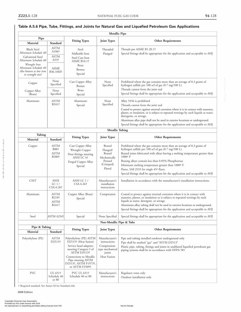
2009 Edition
Z223.1-128 NATIONAL FUEL GAS CODE 54-128
† Required standard. See Annex M for Standard title.
Metallic Pipe
Pipe
Material
Black SteelMinimum Schedule 40
Galvanized SteelMinimum Schedule 40
Wrought IronMinimum Schedule 40Also known as low iron
or wrought steel
Copper
Copper Alloy(Brass)
NoneSpecified
NoneSpecified
Cast Copper AlloyBronzeBrass
Special
NoneSpecified
Prohibited where the gas contains more than an average of 0.3 grains ofhydrogen sulfide per 100 scf of gas (0.7 mg/100 L).Threads cannot form the joint sealSpecial fittings shall be appropriate for the application and acceptable to AHJ
Aluminum ASTMB241†
AluminumSpecial
NoneSpecified
Alloy 5456 is prohibitedThreads cannot form the joint sealCoated to protect against external corrosion where it is in contact with masonry,plaster, or insulation, or is subject to repeated wettings by such liquids as water,detergents, or sewage.Aluminum alloy pipe shall not be used in exterior locations or underground.Special fittings shall be appropriate for the application and acceptable to AHJ
Copper ASTMB88†ASTMB280†
Cast Copper AlloyWrought Copper
Press fittings meetingANSI LC 4†
Forged Copper AlloySpecial
BrazedFlanged/Brazed
MechanicallyPressed
(Crimped)Flared
Prohibited where the gas contains more than an average of 0.3 grains ofhydrogen sulfide per 100 scf of gas (0.7 mg/100 L).Brazed joints fabricated with alloys having a melting temperature greater than1000º FBrazing alloys contain less than 0.05% PhosphorousMinimum melting temperature greater than 1000º FFlares, SAE J533 for single 45º flaresSpecial fittings shall be appropriate for the application and acceptable to AHJ
CSST ANSILC 1 /
CSA 6.26†
ANSI LC 1 /CSA 6.26†
Manufacturer’sinstallationinstructions
Installation in accordance with the manufacturer’s installation instructions.
Aluminum ASTMB210†ASTMB241†
Copper Alloy (Brass)Special
Compression Coated to protect against external corrosion where it is in contact withmasonry, plaster, or insulation or is subject to repeated wettings by suchliquids as water, detergent, or sewage.Aluminum-alloy tubing shall not be used in exterior locations or underground.Special fittings shall be appropriate for the application and acceptable to AHJ
Steel ASTM A254† Special None Specified Special fittings shall be appropriate for the application and acceptable to AHJ
Polyethylene (PE) ASTMD2513†
Polyethylene (PE) ASTMD2513† (Heat fusion)Service head adaptersmeeting Category I of
ASTM D2513†Connections to Metallic
Pipe meeting ASTMD2513†, ASTM F1973†,
or ASTM F2509†
Manufacturer’sinstructions
Compression-type mechanical
jointsHeat Fusion
Pipe and tubing installed outdoors underground onlyPipe shall be marked “gas” and “ASTM D2513”Plastic pipe, tubing, fittings and joints in undiluted liquefied petroleum gaspiping systems shall be in accordance with NFPA 58†
PVC UL 651†Schedule 40
or 80
PVC UL 651†Schedule 40 or 80
Manufacturer’sinstructions
Regulator vents onlyOutdoor installation only
ASTMA106†
SteelMalleable IronSteel Cast IronASME B16.1†
BrassBronzeSpecial
ThreadedFlanged
Threads per ASME B1.20.1†Special fittings shall be appropriate for the application and acceptable to AHJ
ASTMA53†
ASMEB36.10M†
Standard
Material Standard
Fitting Types Joint Types Other Requirements
Metallic Tubing
Tubing
Material StandardFitting Types Joint Types Other Requirements
Non-Metallic Pipe & Tube
Pipe & TubingFitting Types Joint Types Other Requirements
Table A.5.6 Pipe, Tube, Fittings, and Joints for Natural Gas and Liquefied Petroleum Gas Applications
Copyright American Gas Association Provided by IHS under license with AGA
Not for ResaleNo reproduction or networking permitted without license from IHS
--`,,```,,,,````-`-`,,`,,`,`,,`---
//^:^^#^~^^""~:@":^*^~$~"#:*~::*^~:^^#~~#^~:^:@
:~*:$"\\
Z223.1-129 ANNEX A 54-129
2009 Edition
standard flow formula located in Annex C but rearranged tosolve for the pipe diameter.
A.6.4.2 High Pressure Formula. The presented formula is thestandard flow formula located in Annex C but rearranged tosolve for the pipe diameter.
A.7.1.3 For information on corrosion protection of under-ground pipe, see NACE RP 0169, Control of ExternalCorrosion on Underground or Submerged Metallic PipingSystems. Information on installation, maintenance, and cor-rosion protection might be available from the gas supplier.
A.7.1.4 The gas supplier can be consulted for recommen-dations.
A.7.2.5 It is the intent that gas piping, shutoff valvesrequired by this code, and regulators be allowed to beinstalled in accessible portions of plenums, accessible ductsused to supply combustion and ventilation air in accor-dance with Section 9.3, and accessible spaces between afixed ceiling and dropped ceiling.
A.7.4.3 Only vertical chases are recognized by the coverage.It is believed that welded joints for a horizontal gas linewould be preferable to a horizontal chase.
A.7.12.4 The mixing blower is acknowledged as a specialcase because of its inability to tolerate control valves or com-parable restrictions between mixing blower and burner(s).With these limitations, mixing blower installations are notrequired to utilize safety blowouts, backfire preventers,explosion heads, flame arresters, or automatic firechecksthat introduce pressure losses.
A.7.12.5.1 For information on venting of deflagrations, seeNFPA 68, Standard on Explosion Protection by DeflagrationVenting.
A.7.12.5.4 Additional interlocks might be necessary for safeoperation of appliances supplied by the gas-mixing machine.
A.7.12.6 (1) Two basic methods are generally used. Onecalls for a separate firecheck at each burner, the other afirecheck at each group of burners. The second method isgenerally more practical if a system consists of many closelyspaced burners.
An approved automatic firecheck should be installed asnear as practical upstream from a flame arrester used forlocal protection where test burners or lighting torches areemployed.
A.7.13.4 NFPA 780, Section 4.14, requires that all ground-ing media including underground metallic piping systemsbe interconnected to provide a common ground potential.These underground piping systems are not permitted to be
substituted for grounding electrodes but must be bonded tothe lightning protection grounding system. Where galvaniccorrosion is of concern, the bond may be made via a sparkgap or gas discharge tube.
A.8.1.1 Because it is sometimes necessary to divide a pipingsystem into test sections and install test heads, connectingpiping, and other necessary appurtenances for testing, it isnot required that the tie-in sections of pipe be pressure-test-ed. Tie-in connections, however, should be tested with anoncorrosive leak detection fluid after gas has been intro-duced and the pressure has been increase sufficiently to givesome indications whether leaks exist.
The test procedure used should be capable of disclosingall leaks in the section being tested and should be selectedafter giving due consideration to the volumetric content ofthe section and to its location.
Under no circumstances should a valve in a line be usedas a bulkhead between gas in one section of the piping sys-tem and test medium in an adjacent section, unless twovalves are installed in series with a valved “telltale” locatedbetween these valves. A valve should not be subjected to thetest pressure unless it can be determined that the valve,including the valve closing mechanism, is designed to safe-ly withstand the test pressure.
A.8.1.4.3 During pressure tests conducted over long peri-ods of time, such as overnight, the effects of temperature onpressure should be considered. Temperature drops can causea drop in pressure great enough to be indicated by the testgauge. These temperature drops may cause test evaluators tothink that a leak exists in the piping system when in fact thepressure drop was caused by a decrease in the ambient tem-perature. See C.8.5 Example 5.
A.8.2.3 See Annex D for a suggested method.
A.8.3 The process of purging a gas pipeline of fuel gas andreplacing the fuel gas with air or charging a gas pipeline thatis full of air with fuel gas require that a significant amountof combustible mixture not be developed within thepipeline or released within a confined space.
A.9.1.1 The American Gas Association, American NationalStandards Institute, and the National Fire ProtectionAssociation do not approve, inspect, or certify any installa-tions, procedures, appliances, equipment, or materials; nordo they approve or evaluate testing laboratories. In deter-mining acceptability of installations, procedures, appli-ances, equipment, or materials, the authority having juris-diction may base acceptance on compliance with AGA,ANSI, CSA or NFPA, or other appropriate standards. Inthe absence of such standards, said authority may require
Copyright American Gas Association Provided by IHS under license with AGA
Not for ResaleNo reproduction or networking permitted without license from IHS
--`,,```,,,,````-`-`,,`,,`,`,,`---
//^:^^#^~^^""~:@":^*^~$~"#:*~::*^~:^^#~~#^~:^:@:~*:$"\\

2009 Edition
Z223.1-130 NATIONAL FUEL GAS CODE 54-130
evidence of proper installation, procedure, or use. Theauthority having jurisdiction may also refer to the listings orlabeling practices [see Section 3.2.3 and Section 3.2.4] of anorganization concerned with product evaluations and isthus in a position to determine compliance with appropri-ate standards for the current production of listed items.Additional information regarding the coordination of appli-ance design, construction, and maintenance can be foundin Annex B.
A.9.1.6 Halogenated hydrocarbons are particularly injuri-ous and corrosive after contact with flames or hot surfaces.
A.9.3 Special Conditions Created by Mechanical Exhaustingor Fireplaces. Operation of exhaust fans, ventilation systems,clothes dryers, or fireplaces can create conditions requiringspecial attention to avoid unsatisfactory operation ofinstalled appliances.
A.9.3.2.1 See Table A.9.3.2.1.
A.9.3.2.2 See Table A.9.3.2.2(a) and Table A.9.3.2.2(b).
A.9.3.2.3 (1) See Figure A.9.3.2.3(1).
A.9.3.3.1 (1) See Figure A.9.3.3.1 (1)(a) and FigureA.9.3.3.1(1)(b).
A.9.3.3.1 (2) See Figure A.9.3.3.1(2).
A.9.3.3.2 See Figure A.9.3.3.2.
Figure A.9.3.2.3(1)All Combustion Air From Adjacent Indoor Spaces
Through Indoor Combustion Air Openings.
Figure A.9.3.3.1(1)(a)All Combustion Air From Outdoors —
Inlet Air From Ventilated Crawl Space andOutlet Air to Ventilated Attic.
Figure A.9.3.3.1(1)(b)All Combustion Air From Outdoors
Through Ventilated Attic.
Copyright American Gas Association Provided by IHS under license with AGA
Not for ResaleNo reproduction or networking permitted without license from IHS
--`,,```,,,,````-`-`,,`,,`,`,,`---
//^:^^#^~^^""~:@":^*^~$~"#:*~::*^~:^^#~~#^~:^:@
:~*:$"\\

2009 Edition
54-131 ANNEX A Z223.1-131
Table A.9.3.2.2(b) Known Air InfiltrationRate Method, Minimum Space Volumefor Fan-Assisted Appliance, For Specified
Infiltration Rates (ACH*)
Space Space SpaceAppliance Volume Volume Volume
Input (ft3) (ft3) (ft3)Btu/hr 0.25 ACH 0.30 ACH 0.35 ACH
5,000 300 250 21410,000 600 500 42915,000 900 750 64320,000 1,200 1,000 85725,000 1,500 1,250 1,07130,000 1,800 1,500 1,28635,000 2,100 1,750 1,50040,000 2,400 2,000 1,71445,000 2,700 2,250 1,92950,000 3,000 2,500 2,14355,000 3,300 2,750 2,35760,000 3,600 3,000 2,57165,000 3,900 3,250 2,78670,000 4,200 3,500 3,00075,000 4,500 3,750 3,21480,000 4,800 4,000 3,42985,000 5,100 4,250 3,64390,000 5,400 4,500 3,85795,000 5,700 4,750 4,071
100,000 6,000 5,000 4,286105,000 6,300 5,250 4,500110,000 6,600 5,500 4,714115,000 6,900 5,750 4,929120,000 7,200 6,000 5,143125,000 7,500 6,250 5,357130,000 7,800 6,500 5,571135,000 8,100 6,750 5,786140,000 8,400 7,000 6,000145,000 8,700 7,250 6,214150,000 9,000 7,500 6,429160,000 9,600 8,000 6,857170,000 10,200 8,500 7,286180,000 10,800 9,000 7,714190,000 11,400 9,500 8,143200,000 12,000 10,000 8,571210,000 12,600 10,500 9,000220,000 13,200 11,000 9,429230,000 13,800 11,500 9,857240,000 14,400 12,000 10,286250,000 15,000 12,500 10,714260,000 15,600 13,000 11,143270,000 16,200 13,500 11,571280,000 16,800 14,000 12,000290,000 17,400 14,500 12,429300,000 18,000 15,000 12,857
*ACH= Air Change per Hour
Table A.9.3.2.2(a) Known Air InfiltrationRate Method, Minimum Space Volumefor Appliances Other Than Fan-Assisted,For Specified Infiltration Rates (ACH*)
Space Space SpaceAppliance Volume Volume Volume
Input (ft3) (ft3) (ft3)Btu/hr 0.25 ACH 0.30 ACH 0.35 ACH
5,000 420 350 30010,000 840 700 60015,000 1,260 1,050 90020,000 1,680 1,400 1,20025,000 2,100 1,750 1,50030,000 2,520 2,100 1,80035,000 2,940 2,450 2,10040,000 3,360 2,800 2,40045,000 3,780 3,150 2,70050,000 4,200 3,500 3,00055,000 4,620 3,850 3,30060,000 5,040 4,200 3,60065,000 5,460 4,550 3,90070,000 5,880 4,900 4,20075,000 6,300 5,250 4,50080,000 6,720 5,600 4,80085,000 7,140 5,950 5,10090,000 7,560 6,300 5,40095,000 7,980 6,650 5,700
100,000 8,400 7,000 6,000105,000 8,820 7,350 6,300110,000 9,240 7,700 6,600115,000 9,660 8,050 6,900120,000 10,080 8,400 7,200125,000 10,500 8,750 7,500130,000 10,920 9,100 7,800135,000 11,340 9,450 8,100140,000 11,760 9,800 8,400145,000 12,180 10,150 8,700150,000 12,600 10,500 9,000160,000 13,440 11,200 9,600170,000 14,280 11,900 10,200180,000 15,120 12,600 10,800190,000 15,960 13,300 11,400200,000 16,800 14,000 12,000210,000 17,640 14,700 12,600220,000 18,480 15,400 13,200230,000 19,320 16,100 13,800240,000 20,160 16,800 14,400250,000 21,000 17,500 15,000260,000 21,840 18,200 15,600270,000 22,680 18,900 16,200280,000 23,520 19,600 16,800290,000 24,360 20,300 17,400300,000 25,200 21,000 18,000
*ACH= Air Change per Hour
Table A.9.3.2.1Standard Method:Required Volume,All Appliances
Appliance RequiredInput Volume
Btu /hr (ft3)5,000 25010,000 50015,000 75020,000 1,00025,000 1,25030,000 1,50035,000 1,75040,000 2,00045,000 2,25050,000 2,50055,000 2,75060,000 3,00065,000 3,25070,000 3,50075,000 3,75080,000 4,00085,000 4,25090,000 4,50095,000 4,750100,000 5,000105,000 5,250110,000 5,500115,000 5,750120,000 6,000125,000 6,250130,000 6,500135,000 6,750140,000 7,000145,000 7,250150,000 7,500160,000 8,000170,000 8,500180,000 9,000190,000 9,500200,000 10,000210,000 10,500220,000 11,000230,000 11,500240,000 12,000250,000 12,500260,000 13,000270,000 13,500280,000 14,000290,000 14,500300,000 15,000
Table A.9.3.2.1, Table A.9.3.2.2 (a), and Table 9.3.2.2 (b) The following tables contains the calculated minimum required vol-umes for the Standard Method and the calculated minimum required volume for the Known Air Infiltration Rate Method.
For SI units, 1 ft3 = 0.028 m3; 1000 Btu/hr = 0.293 kW
Copyright American Gas Association Provided by IHS under license with AGA
Not for ResaleNo reproduction or networking permitted without license from IHS
--`,,```,,,,````-`-`,,`,,`,`,,`---
//^:^
^#^~
^^""
~:@
":^*^
~$~"
#:*~
::*^~
:^^#
~~#^
~:^:
@:~
*:$"
\\

54-132 NATIONAL FUEL GAS CODE Z223.1-132
2009 Edition
Figure A.9.3.3.1(2)All Combustion Air From Outdoors
Through Horizontal Ducts.
Figure A.9.3.3.2All Combustion Air From Outdoors
Through Single Combustion Air Opening.
A.9.6.1.3 The expansion and contraction of the heater andthe vibration from the blower motor may lead to workhardening of the rigid pipe or semi-rigid metallic tubing,which may ultimately lead to fractures and leakage.Connectors for this type of heater should have adequateflexibility, temperature rating, and vibration resistance to
accommodate the characteristics of the heater. Such flexibleconnectors for suspended heaters should be:(1) Determined to be appropriate for the application(2) Specified by the heater manufacturer(3) Installed in accordance with the manufacturer's instal-
lation instructions
A.10.1.2 Also see Prohibited Installations, 10.6.1, 10.7.1,10.8.2, 10.9.2 and 10.23.1.
A.10.2.6 Reference can be made to NFPA 90A, Standardfor the Installation of Air-Conditioning and VentilatingSystems, or NFPA 90B, Standard for the Installation of WarmAir Heating and Air-Conditioning Systems.
A.10.3.5 Paragraph 10.3.5 differs in the NFPA 54 andANSI Z223.1 publications. The NFPA 54 paragraph wasrevised based on an amendment approved in the NFPAprocess. A similar change has been proposed as an amend-ment to ANSI Z223.1. The NFPA 54 paragraph states:
10.3.5 Low Water Cutoff. All Hot water boilers and allsteam boilers shall be provided with an automatic meansto shut off the fuel supply to the burner(s) if the boilerwater level drops below the lowest safe water line. In lieuof the low water cutoff, water tube or coil-type boilerswhich require forced circulation to prevent overheatingand failure shall have an approved flow sensing devicearranged to shut down the boiler when the flow rate isinadequate to protect the boiler against overheating.
A.10.3.6 For details of requirements on low-pressure heatingboiler safety devices, refer to ASME Boiler and Pressure VesselCode, Section IV, “Rules for Construction of Heating Boilers.”
A.10.3.7.3 Reference can be made to NFPA 90A, Standardfor the Installation of Air-Conditioning and VentilatingSystems, or to NFPA 90B, Standard for the Installation ofWarm Air Heating and Air-Conditioning Systems.
A.10.6.1 For information on decorative appliances forinstallation in vented fireplaces, see ANSI Z21.60/CGA2.26, Decorative Gas Appliances for Installation in Solid-FuelBurning Fireplaces.
A.10.7.1 For information on vented gas fireplaces, seeANSI Z21.50/CSA 2.22, Vented Gas Fireplaces.
A.10.9.2.2 Recirculation of room air can be hazardous inthe presence of flammable solids, liquids, and gases, explo-sive materials (e.g., grain dust, coal dust, gun powder), andsubstances (e.g., refrigerants, aerosols) that can becometoxic when exposed to flame or heat.
A.10.12.8 Where exhaust fans are used for ventilation, pre-cautions might be necessary to avoid interference with the
Copyright American Gas Association Provided by IHS under license with AGA
Not for ResaleNo reproduction or networking permitted without license from IHS
--`,,```,,,,````-`-`,,`,,`,`,,`---
//^:^^#^~^^""~:@":^*^~$~"#:*~::*^~:^^#~~#^~:^:@
:~*:$"\\

Z223.1-133 ANNEX A 54-133
2009 Edition
operation of the appliance.
A.10.23.1 It is recommended that space heating appliancesinstalled in all bedrooms or rooms generally kept closed beof the direct vent type. [See Section 10.27.]
A.10.28.7 A hole near the top of a cold water inlet tube thatenters the top of the water heater or tank is commonlyaccepted for this purpose.
A.11.1.1 It should be recognized that for most burners, theinput rate can be changed only slightly by changing theinput pressure. Burner input shall be checked in accordancewith the appliance manufacturer’s installation instructions.If no appliance instructions are provided, burner input ratecan be checked as follows:(1) Checking Burner Input Using a Meter (clocking). To
check the Btu/hr input rate, the test hand on the gasmeter should be timed for at least one revolution andthe input determined from this timing. Test dials aregenerally marked 1⁄2, 1, 2, or 5 ft3/revolution depend-ing on the size of the meter. Instructions for convert-ing the test hand readings to cubic feet per hour aregiven in Table A.11.1.1. This table is provided for spe-cific gas pressures within the meters and give gas flowrate (corrected to standard conditions) in cubic feet ofgas per hour. Standard temperature is 60°F, and stan-dard pressure is 29.92 inches of mercury. Measure thetime for at least one revolution of a dial. Look up thegas flow rate in Table A.11.1.1.Gas flow rates can be calculated for meter pressuresother than in these tables in the following manner.A pressure adjustment factor F should be determinedfor use in the gas input calculation for the gas pressuredifference ∆P between the meter inlet and the atmos-phere. The gas supplier can provide the pressure at themeter inlet. The pressure adjustment factor F is calcu-lated with the following formula. Table A.11.1.1 wascalculated with this formula.
F = ∆P + (B × 13.596)29.92 × 13.596
where:F = the pressure correction factor.
∆P = the meter inlet pressure (inches of watercolumn).
B = the barometric pressure, unadjusted to sealevel (inches of mercury)
NOAA weather reports barometric pressure inches ofmercury, adjusted to sea level. The sea level adjustmentmust be subtracted from the barometric pressurereported by NOAA weather. The local sea level adjust-
ment can be obtained from NOAA.EXAMPLE:
NOAA reported barometric pressure to be 30.12inches of mercury for a city at 250 feet elevation.The barometric pressure adjustment for 250 feet is0.27 inches of mercury. Subtract the local sea leveladjustment from the NOAA barometric pressure toget the unadjusted barometric pressure.
30.12 - 0.27 = 29.85The gas flow rate Q is calculated with the followingformula.
Q = F × Cwhere:
Q = gas flow rate at standard conditions (ft3/hr)F = the pressure adjustment factor.C = the timed gas flow rate (ft3/hr)
The gas input rate I is calculated with thefollowing formula.
I = Q × HHVwhere:
I = gas input rate (Btu/hr)Q = the gas flow rate at standard conditions
(ft3/hr).HHV = the average Higher Heat Value of the gas
at standard temperature and pressureconditions (Btu/ft3), which can beobtained from the gas supplier.
Appliances can be seriously overfired if the timedmeter gas flow rate used to set input rate is not adjust-ed for meter pressure. At 2 psi meter pressure an appli-ance would be 13 percent overfired if the gas flow rateis not adjusted for meter pressure.
(2) Checking Burner Input by Using Orifice Pressure Drop andOrifice Size. The fixed orifice size for each burner can bedetermined in accordance with Table F.1 for utility gasesand Table F.2 for undiluted liquefied petroleum gases.
A.11.2 Normally, the primary air adjustment should first beset to give a soft blue flame having luminous tips and thenincreased to a point where the yellow tips just disappear. Ifthe burner cannot be so adjusted, the manufacturer or serv-ing gas supplier should be contacted.
A.11.6 A procedure for checking draft can be found inAnnex H, steps 7, 8, and 10 through 14.
A.12.3.3 Information on the construction and installationof ventilating hoods can be obtained from NFPA 96,Standard for Ventilation Control and Fire Protection ofCommercial Cooking Operations.
A.12.4.4 See A.12.3.3.
Copyright American Gas Association Provided by IHS under license with AGA
Not for ResaleNo reproduction or networking permitted without license from IHS
--`,,```,,,,````-`-`,,`,,`,`,,`---
//^:^
^#^~
^^""
~:@
":^*^
~$~"
#:*~
::*^~
:^^#
~~#^
~:^:
@:~
*:$"
\\

2009 Edition
Z223.1-134 NATIONAL FUEL GAS CODE 54-134
Table A.11.1.1 Gas Flow Rate to Burner in Cubic Feet per Hour at Standard Temperature and Pressure
Meter 7.0 in. w.c. or 0.25 psi 11.0 in. w.c. or 0.40 psi 55.4 in. w.c. or 2 psiPressure:
Seconds Size of Test Meter Dial
for OneRevolution
1⁄2 ft3 1 ft3 2 ft3 5 ft3 1⁄2 ft3 1 ft3 2 ft3 5 ft3 1⁄2 ft3 1 ft3 2 ft3 5 ft3
10 183 366 732 1831 185 370 739 1849 204 409 818 2044
11 166 333 666 1664 168 336 672 1680 186 372 743 1859
12 153 305 610 1526 154 308 616 1540 170 341 681 1704
13 141 282 563 1408 142 284 569 1422 157 315 629 1573
14 131 262 523 1308 132 264 528 1320 146 292 584 1460
15 122 244 488 1221 123 246 493 1232 136 273 545 1363
16 114 229 458 1144 116 231 462 1155 128 256 511 1278
17 108 215 431 1077 109 217 435 1087 120 241 481 1203
18 102 203 407 1017 103 205 411 1027 114 227 454 1136
19 96 193 385 964 97 195 389 973 108 215 430 1076
20 92 183 366 915 92 185 370 924 102 204 409 1022
21 87 174 349 872 88 176 352 880 97 195 389 974
22 83 166 333 832 84 168 336 840 93 186 372 929
23 80 159 318 796 80 161 321 804 89 178 356 889
24 76 153 305 763 77 154 308 770 85 170 341 852
25 73 146 293 732 74 148 296 739 82 164 327 818
26 70 141 282 704 71 142 284 711 79 157 315 786
27 68 136 271 678 68 137 274 685 76 151 303 757
28 65 131 262 654 66 132 264 660 73 146 292 730
29 63 126 253 631 64 127 255 637 70 141 282 705
30 61 122 244 610 62 123 246 616 68 136 273 681
31 59 118 236 591 60 119 239 596 66 132 264 660
32 57 114 229 572 58 116 231 578 64 128 256 639
33 55 111 222 555 56 112 224 560 62 124 248 620
34 54 108 215 538 54 109 217 544 60 120 241 601
35 52 105 209 523 53 106 211 528 58 117 234 584
36 51 102 203 509 51 103 205 513 57 114 227 568
37 49 99 198 495 50 100 200 500 55 111 221 553
38 48 96 193 482 49 97 195 486 54 108 215 538
39 47 94 188 469 47 95 190 474 52 105 210 524
40 46 92 183 458 46 92 185 462 51 102 204 511
41 45 89 179 447 45 90 180 451 50 100 199 499
42 44 87 174 436 44 88 176 440 49 97 195 487
43 43 85 170 426 43 86 172 430 48 95 190 475
44 42 83 166 416 42 84 168 420 46 93 186 465
45 41 81 163 407 41 82 164 411 45 91 182 454
46 40 80 159 398 40 80 161 402 44 89 178 444
47 39 78 156 390 39 79 157 393 43 87 174 435
48 38 76 153 381 39 77 154 385 43 85 170 426
49 37 75 149 374 38 75 151 377 42 83 167 417
50 37 73 146 366 37 74 148 370 41 82 164 409
Copyright American Gas Association Provided by IHS under license with AGA
Not for ResaleNo reproduction or networking permitted without license from IHS
--`,,```,,,,````-`-`,,`,,`,`,,`---
//^:^^#^~^^""~:@":^*^~$~"#:*~::*^~:^^#~~#^~:^:@:~*:$"\\

2009 Edition
54-135 ANNEX A Z223.1-135
Table A.11.1.1 Gas Flow Rate to Burner in Cubic Feet per Hour at Standard Temperature and Pressure (continued)
Meter 7.0 in. w.c. or 0.25 psi 11.0 in. w.c. or 0.40 psi 55.4 in. w.c. or 2 psiPressure:
Seconds Size of Test Meter Dialfor One
Revolution1⁄2 ft3 1 ft3 2 ft3 5 ft3 1⁄2 ft3 1 ft3 2 ft3 5 ft3 1⁄2 ft3 1 ft3 2 ft3 5 ft3
51 36 72 144 359 36 72 145 362 40 80 160 401
52 35 70 141 352 36 71 142 355 39 79 157 393
53 35 69 138 345 35 70 140 349 39 77 154 386
54 34 68 136 339 34 68 137 342 38 76 151 379
55 33 67 133 333 34 67 134 336 37 74 149 372
56 33 65 131 327 33 66 132 330 37 73 146 365
57 32 64 128 321 32 65 130 324 36 72 143 359
58 32 63 126 316 32 64 127 319 35 71 141 352
59 31 62 124 310 31 63 125 313 35 69 139 347
60 31 61 122 305 31 62 123 308 34 68 136 341
62 30 59 118 295 30 60 119 298 33 66 132 330
64 29 57 114 286 29 58 116 289 32 64 128 321
66 28 55 111 277 28 56 112 280 31 62 124 310
68 27 54 108 269 27 54 109 272 30 60 120 301
70 26 52 105 262 26 53 106 264 29 58 117 292
72 25 51 102 254 26 51 103 257 28 57 114 284
74 25 49 99 247 25 50 100 250 28 55 111 276
76 24 48 96 241 24 49 97 243 27 54 108 269
78 23 47 94 235 24 47 95 237 26 52 105 262
80 23 46 92 229 23 46 92 231 26 51 102 256
82 22 45 89 223 23 45 90 225 25 50 100 249
84 22 44 87 218 22 44 88 220 24 49 97 243
86 21 43 85 213 21 43 86 215 24 48 95 238
88 21 42 83 208 21 42 84 210 23 46 93 232
90 20 41 81 203 21 41 82 205 23 45 91 227
94 19 39 78 195 20 39 79 197 22 43 87 217
98 19 37 75 187 19 38 75 189 21 42 83 209
100 18 37 73 183 18 37 74 185 20 41 82 204
104 18 35 70 176 18 36 71 178 20 39 79 197
108 17 34 68 170 17 34 68 171 19 38 76 189
112 16 33 65 163 17 33 66 165 18 37 73 183
116 16 32 63 158 16 32 64 159 18 35 70 176
120 15 31 61 153 15 31 62 154 17 34 68 170
130 14 28 56 141 14 28 57 142 16 31 63 157
140 13 26 52 131 13 26 53 132 15 29 58 146
150 12 24 49 122 12 25 49 123 14 27 55 136
160 11 23 46 114 12 23 46 116 13 26 51 128
170 11 22 43 108 11 22 43 109 12 24 48 120
180 10 20 41 102 10 21 41 103 11 23 45 114
190 10 19 39 96 10 19 39 97 11 22 43 108
200 9 18 37 92 9 18 37 92 10 20 41 102
Note: To convert to Btu per hour, multiply the cubic feet per hour of gas by the Btu per cubic foot heating value of the gas used.
Copyright American Gas Association Provided by IHS under license with AGA
Not for ResaleNo reproduction or networking permitted without license from IHS
--`,,```,,,,````-`-`,,`,,`,`,,`---
//^:^
^#^~
^^""
~:@
":^*^
~$~"
#:*~
::*^~
:^^#
~~#^
~:^:
@:~
*:$"
\\

54-136 NATIONAL FUEL GAS CODE Z223.1-136
2009 Edition
A.12.6.1.3 For information on the installation of gas ventsin existing masonry chimneys, see Section 12.7.
A.12.6.5.3 Reference can also be made to the chapter onchimney, gas vent, and fireplace systems of the ASHRAEHandbook — HVAC Systems and Equipment.
A.12.7.3.1 Additional information on sizing venting sys-tems can be found in the following:(1) Tables in Chapter 13(2) The appliance manufacturer’s instructions(3) The vent system manufacturer’s sizing instructions(4) Drawings, calculations, and specifications provided by
the vent system manufacturer(5) Drawings, calculations, and specifications provided by
a competent person(6) The chapter on chimney, gas vent, and fireplace sys-
tems of the ASHRAE Handbook — HVAC Systems andEquipment.
Category I appliances may be either draft hood-
equipped or fan-assisted combustion system in design.Different vent design methods are required for draft hood-equipped and fan-assisted combustion system appliances.
A.12.8.2 Data on winter design temperature can be foundin Figure G.2.4 and the 1993 edition of the ASHRAEHandbook — Fundamentals.
A.12.8.4.1 The prohibition only applies to a vent entirelyconstructed of single-wall metal pipe located in a residentialoccupancy. The prohibition does not apply to single wallvent connectors used to connect an appliance to the vent aspermitted in section 12.11 and Chapter 13.
A.12.8.5 (1) Reference can also be made to the chapter onchimney, gas vent, and fireplace systems of the ASHRAEHandbook — HVAC Systems and Equipment.
A.12.9 See Figure A.12.9.
A.12.11.3 Reference can also be made to the chapter onchimney, gas vent, and fireplace systems of the ASHRAEHandbook — HVAC Systems and Equipment.
Figure A.12.9Exit terminals of mechanical draft and direct-vent venting systems.
Copyright American Gas Association Provided by IHS under license with AGA
Not for ResaleNo reproduction or networking permitted without license from IHS
--`,,```,,,,````-`-`,,`,,`,`,,`---
//^:^^#^~^^""~:@":^*^~$~"#:*~::*^~:^^#~~#^~:^:@
:~*:$"\\
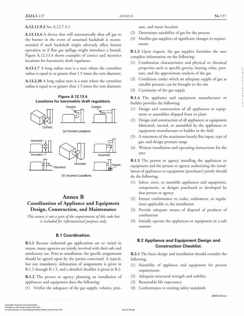
Z223.1-137 ANNEX B 54-137
2009 Edition
A.12.11.9.2 See A.12.7.3.1.
A.12.13.4 A device that will automatically shut off gas tothe burner in the event of sustained backdraft is recom-mended if such backdraft might adversely affect burneroperation or if flue gas spillage might introduce a hazard.Figure A.12.13.4 shows examples of correct and incorrectlocations for barometric draft regulators.
A.13.1.7 A long radius turn is a turn where the centerlineradius is equal to or greater than 1.5 times the vent diameter.
A.13.2.20 A long radius turn is a turn where the centerlineradius is equal to or greater than 1.5 times the vent diameter.
Figure A.12.13.4.Locations for barometric draft regulators.
Annex BCoordination of Appliance and Equipment
Design, Construction, and MaintenanceThis annex is not a part of the requirements of this code but
is included for informational purposes only.
B.1 Coordination.
B.1.1 Because industrial gas applications are so varied innature, many agencies are jointly involved with their safe andsatisfactory use. Prior to installation, the specific assignmentsshould be agreed upon by the parties concerned. A typical,but not mandatory, delineation of assignments is given inB.1.2 through B.1.5, and a detailed checklist is given in B.2.
B.1.2 The person or agency planning an installation ofappliances and equipment does the following:(1) Verifies the adequacy of the gas supply, volume, pres-
sure, and meter location(2) Determines suitability of gas for the process(3) Notifies gas suppliers of significant changes in require-
ments
B.1.3 Upon request, the gas supplier furnishes the usercomplete information on the following:(1) Combustion characteristics and physical or chemical
properties such as specific gravity, heating value, pres-sure, and the approximate analysis of the gas
(2) Conditions under which an adequate supply of gas atsuitable pressure can be brought to the site
(3) Continuity of the gas supply
B.1.4 The appliance and equipment manufacturer orbuilder provides the following:(1) Design and construction of all appliances or equip-
ment or assemblies shipped from its plant(2) Design and construction of all appliances or equipment
fabricated, erected, or assembled by the appliances orequipment manufacturer or builder in the field
(3) A statement of the maximum hourly Btu input, type ofgas, and design pressure range
(4) Written installation and operating instructions for theuser
B.1.5 The person or agency installing the appliances orequipment and the person or agency authorizing the instal-lation of appliances or equipment (purchaser) jointly shoulddo the following:(1) Select, erect, or assemble appliances and equipment,
components, or designs purchased or developed bythat person or agency
(2) Ensure conformance to codes, ordinances, or regula-tions applicable to the installation
(3) Provide adequate means of disposal of products ofcombustion
(4) Initially operate the appliances or equipment in a safemanner
B.2 Appliance and Equipment Design andConstruction Checklist.
B.2.1 The basic design and installation should consider thefollowing:(1) Suitability of appliance and equipment for process
requirements(2) Adequate structural strength and stability(3) Reasonable life expectancy(4) Conformance to existing safety standards
Copyright American Gas Association Provided by IHS under license with AGA
Not for ResaleNo reproduction or networking permitted without license from IHS
--`,,```,,,,````-`-`,,`,,`,`,,`---
//^:^
^#^~
^^""
~:@
":^*^
~$~"
#:*~
::*^~
:^^#
~~#^
~:^:
@:~
*:$"
\\
54-138 NATIONAL FUEL GAS CODE Z223.1-138
2009 Edition
(5) Adequate combustion space and venting(6) Means for observation and inspection of combustion
B.2.2 Materials of construction used, other than pipe, fit-tings, and valves, should provide reasonable life expectancyfor the service intended and should be capable of satisfacto-rily withstanding the following:(1) Operating temperatures(2) Chemical action(3) Thermal shock(4) Load stresses
B.2.3 Combustion systems should be selected for the charac-teristics of the available gas so that they will operate properlyat the elevation at point of use and produce the following:(1) Proper heat distribution(2) Adequate operating temperature range(3) Suitable flame geometry(4) Flame stability(5) Operating flexibility(6) Desired heating chamber atmosphere
B.2.4 Pipe, fittings, and valves should conform to applica-ble American National Standards as indicated in Section5.6. Piping, bushings, and material in fittings should notbe selected nor used until the following factors have beenconsidered:(1) Correct size to handle required volume (consideration
of pressure drop in controls and manifolds is particu-larly important in low pressure systems)
(2) Material specifications suitable for pressures and tem-peratures encountered
(3) Adequate supports and protection against physicaldamage
(4) Tight assembly and thorough leak inspection(5) Use of sufficient unions and flanges, where permitted,
for convenient field replacement or repair(6) Arrangement of piping to provide accessibility for appli-
ance and equipment adjustments and freedom fromthermal damage
B.2.5 Information concerning the characteristics of the gasand electricity available at the point of utilization should bespecific and complete. Gas controls and electrical systemsshould be selected to conform to these characteristics,which include the following:(1) Gas characteristics: Heat content, pressure, specific
gravity, and approximate analysis(2) Electrical characteristics: Voltages, number of phases,
and frequencies for both control and power
circuits
(3) Location of electrical equipment and wiring to avoidthermal damage and excessive concentrations of dust,dirt, or foreign material
(4) Requirements of applicable electrical codes and stan-dards, with particular reference to NFPA 70®, Article500, of the National Electrical Code®.
B.2.6 Temperature controls, if used, should be selected withconsideration of the following:
(1) Range and type of instruments and sensing elements
(2) Type of control action
(3) Suitability for service required
(4) Correlation of control instruments with operatingequipment
B.2.7 In enclosed chambers, the accumulation of gas-air orsolvent-air mixtures that can be accidentally ignited consti-tutes a potential hazard to life and property. For this reason,consideration should be given to the selection and installa-tion of suitable protective equipment. The selection of a sat-isfactory protective system and components not otherwisecovered by existing codes or standards should be based onthe requirements of each individual installation after con-sultation with the various interested parties, including theuser, designer, insurance company, and local authoritieshaving jurisdiction. Factors and considerations involved inthe selection of protective equipment include the following:
(1) Feasibility of its installation
(2) Its adaptability to process and control requirements
(3) Conformance to existing standards, ordinances, require-ments, and other regulations that apply. [See Chapter2and Annex M for listing of standards and specifications.]
B.3 Maintenance of Appliances and Equipment.
B.3.1 These recommendations are prepared for mainte-nance of appliances and equipment. Special types of appli-ances and equipment demand special attention.
B.3.2 Burners and pilots should be kept clean and in properoperating condition. Burner refractory parts should be exam-ined at frequent regular intervals to ensure good condition.
B.3.3 Where automatic flame safeguards are used, a com-plete shutdown and restart should be made at frequentintervals to check the components for proper operation.
B.3.4 Other Safeguard Equipment.
B.3.4.1 Accessory safeguard equipment, such as manualreset valves with pressure or vacuum switches, high temper-
Copyright American Gas Association Provided by IHS under license with AGA
Not for ResaleNo reproduction or networking permitted without license from IHS
--`,,```,,,,````-`-`,,`,,`,`,,`---
//^:^^#^~^^""~:@":^*^~$~"#:*~::*^~:^^#~~#^~:^:@
:~*:$"\\

Z223.1-139 ANNEX C 54-139
2009 Edition
ature limit switches, draft controls, shutoff valves, airflow
switches, door switches, and gas valves, should be operated
at frequent regular intervals to ensure proper functioning. If
inoperative, they should be repaired or replaced promptly.
B.3.4.2 Where firechecks are installed in gas-air mixture
piping to prevent flashbacks from traveling farther
upstream, the pressure loss across the firechecks should be
measured at regular intervals. When excessive pressure loss
is found, screens should be removed and cleaned. Water-
type backfire checks should be inspected at frequent regular
intervals and liquid level maintained.
B.3.4.3 All safety shutoff valves should be checked for leak-
age and proper operation at frequent regular intervals.
B.3.5 Auxiliary Devices.
B.3.5.1 A necessary part of the appliance or equipment
maintenance is the proper maintenance of auxiliary devices.
Maintenance instructions as supplied by the manufacturers
of these devices should be followed.
B.3.5.2 Gas combustion systems, including blowers,
mechanical mixers, control valves, temperature control
instruments, air valves, and air filters, should be kept clean
and should be examined at frequent regular intervals.
B.3.5.3 Necessary repairs and replacements should be made
promptly.
B.3.6 Regulator and zero governor vents and impulse or
control piping and tubing should be kept clear. Regulator
valves that operate improperly should be cleaned, repaired,
or replaced promptly.
B.3.7 A necessary part of the appliance and equipment
maintenance is the proper maintenance of the gas piping
system. It is recommended that gas piping be inspected and
tested for leakage at regular intervals in accordance with the
provisions of 8.1.5. Air piping should be kept internally
clean to prevent accumulation of dust, lint, and grease in air
jets and valves. Where conditions warrant, filters should be
installed at the intake to the fans.
B.3.8 Stand-by or substitute fuel equipment and systems
for appliances or equipment should be kept in good operat-
ing condition and tested periodically.
B.3.9 An adequate supply of repair parts should be
maintained.
Annex CSizing and Capacities of Gas Piping
This annex is not a part of the requirements of this code butis included for informational purposes only.
C.1 Sizing Factors.
The first goal of determining the pipe sizing of a fuel gaspiping system is to be assured that there is sufficient gaspressure at the inlet to each appliance. The majority of sys-tems are residential, and the appliances will all have thesame, or nearly the same, requirement for minimum gaspressure at the appliance inlet. This pressure will be about 5in. w.c., which is enough for proper operation of the appli-ance regulator to deliver about 3.5 in. w.c. (3.4 kPa) to theburner itself. The pressure drop in the piping is subtractedfrom the source delivery pressure to verify that the mini-mum is available at the appliance.
There are other systems, however, where the requiredinlet pressure to the different appliances may be quite var-ied. In such cases, the greatest inlet pressure required mustbe satisfied, as well as the farthest appliance, which is almostalways the critical appliance in small systems.
There is an additional requirement to be observedbesides the capacity of the system at 100% flow. Thatrequirement is that at minimum flow, the pressure at theinlet to any appliance does not exceed the pressure rating ofthe appliance regulator. This would seldom be of concern insmall systems if the source pressure is 1⁄ 2 psi (14 in. w.c.) orless, but it should be verified for systems with greater gaspressure at the point of supply.
C.2 General Piping Considerations.
To determine the size of piping used in a gas piping sys-tem, the following factors must be considered:(1) Allowable loss in pressure from point of delivery to
appliance(2) Maximum gas demand(3) Length of piping and number of fittings(4) Specific gravity of the gas(5) Diversity factor
For any gas piping system, or special appliance, or forconditions other than those covered by the tables providedin this code, such as longer runs, greater gas demands, orgreater pressure drops, the size of each gas piping systemshould be determined by standard engineering practicesacceptable to the authority having jurisdiction.
Copyright American Gas Association Provided by IHS under license with AGA
Not for ResaleNo reproduction or networking permitted without license from IHS
--`,,```,,,,````-`-`,,`,,`,`,,`---
//^:^^#^~^^""~:@":^*^~$~"#:*~::*^~:^^#~~#^~:^:@
:~*:$"\\

54-140 NATIONAL FUEL GAS CODE Z223.1-140
2009 Edition
C.3 Description of Tables.
C.3.1 General. The quantity of gas to be provided at eachoutlet should be determined, whenever possible, directlyfrom the manufacturer’s gas input Btu/hr rating of theappliance that will be installed. In case the ratings of theappliances to be installed are not known, Table 5.4.2.1shows the approximate consumption (in Btu per hour) ofcertain types of typical household appliances.
To obtain the cubic feet per hour of gas required, dividethe total Btu/hr input of all appliances by the average Btuheating value per cubic ft of the gas. The average Btu percubic ft of the gas in the area of the installation can beobtained from the serving gas supplier.
C.3.2 Low Pressure Natural Gas Tables. Capacities for gasat low pressure [less than 2.0 psi (14 kPa gauge)] in cubic feetper hour of 0.60 specific gravity gas for different sizes andlengths are shown in Table 6.2(a) and Table 6.2(b) for ironpipe or equivalent rigid pipe, in Table 6.2(f ) through Table6.2(i) for smooth wall semi-rigid tubing, and in Table6.2(m) through Table 6.2(o) for corrugated stainless steeltubing. Table 6.2(a) and Table 6.2(f ) are based upon a pres-sure drop of 0.3 in. w.c. (75 Pa), whereas Table 6.2(b), Table6.2(g), and Table 6.2(m) are based upon a pressure drop of0.5 in. w.c. (125 Pa). Table 6.2(h), Table 6.2(n), and Table6.2(o) are special low-pressure applications based upon pres-sure drops greater than 0.5 in. w.c. (125 Pa). In using thesetables 6.2(h), 6.2(n), or 6.2(o), an allowance (in equivalentlength of pipe) should be considered for any piping run withfour or more fittings [see Table C.3.2].
C.3.3 Undiluted Liquefied Petroleum Tables. Capacitiesin thousands of Btu per hour of undiluted liquefied petrole-um gases based on a pressure drop of 0.5 in. w.c. (125 Pa) fordifferent sizes and lengths are shown in Table 6.3(d) for ironpipe or equivalent rigid pipe, in Table 6.3(f ) for smooth wallsemi-rigid tubing, in Table 6.3(h) for corrugated stainlesssteel tubing, and in Table 6.3(k) and Table 6.3(m) for poly-ethylene plastic pipe and tubing. Table 6.3(i) and Table 6.3(j)for corrugated stainless steel tubing and Table 6.3(l) for poly-ethylene plastic pipe are based on operating pressures greaterthan 0.5 psi (3.5 kPa) and pressure drops greater than 0.5 in.w.c. (125 Pa). In using these tables, an allowance (in equiva-lent length of pipe) should be considered for any piping runwith four or more fittings [see Table C.3.2].
C.3.4 Natural Gas Specific Gravity. Gas piping systemsthat are to be supplied with gas of a specific gravity of 0.70or less can be sized directly from the tables provided in thiscode, unless the authority having jurisdiction specifies thata gravity factor be applied. Where the specific gravity of the
gas is greater than 0.70, the gravity factor should be applied.Application of the gravity factor converts the figures
given in the tables provided in this code to capacities foranother gas of different specific gravity. Such application isaccomplished by multiplying the capacities given in thetables by the multipliers shown in Table C.3.4. In case theexact specific gravity does not appear in the table, choosethe next higher value specific gravity shown.
C.3.5 Higher Pressure Natural Gas Tables. Capacities forgas at pressures of 2.0 psi (14 kPa gauge) and greater incubic feet per hour of 0.60 specific gravity gas for differentsizes and lengths are shown in Table 6.2(c) through Table6.2(e) for iron pipe or equivalent rigid pipe, Table 6.2(j)through Table 6.2(l) for semi-rigid tubing, Table 6.2(p) andTable 6.2(q) for corrugated stainless steel tubing, and Table6.2(t) for polyethylene plastic pipe.
TABLE C.3.4
Multipliers To Be Used With Table 6.2(a)SPECIAL USE: Through Table 6.2(v) When The Specific
Gravity Of The Gas Is Other Than 0.60Specific SpecificGravity Multiplier Gravity Multiplier
.35 1.31 1.00 .78
.40 1.23 1.10 .74
.45 1.16 1.20 .71
.50 1.10 1.30 .68
.55 1.04 1.40 .66
.60 1.00 1.50 .63
.65 .96 1.60 .61
.70 .93 1.70 .59
.75 .90 1.80 .58
.80 .87 1.90 .56
.85 .84 2.00 .55
.90 .82 2.10 .54
C.4 Use of Capacity Tables.
C.4.1 The Longest Length Method. This sizing method isconservative in its approach by applying the maximumoperating conditions in the system as the norm for the sys-tem and by setting the length of pipe used to size any givenpart of the piping system to the maximum value.
To determine the size of each section of gas piping in asystem within the range of the capacity tables, proceed as fol-lows. (Also see sample calculations included in this Annex.)(1) Divide the piping system into appropriate segments con-
Copyright American Gas Association Provided by IHS under license with AGA
Not for ResaleNo reproduction or networking permitted without license from IHS
--`,,```,,,,````-`-`,,`,,`,`,,`---
//^:^
^#^~
^^""
~:@
":^*^
~$~"
#:*~
::*^~
:^^#
~~#^
~:^:
@:~
*:$"
\\

Z223.1-141 ANNEX C 54-141
2009 Edition
sistent with the presence of tees, branch lines, and mainruns. For each segment, determine the gas load (assum-ing all appliances operate simultaneously) and its overalllength. An allowance (in equivalent length of pipe) asdetermined from Table C.3.2 shall be considered forpiping segments that include four or more fittings.
(2) Determine the gas demand of each appliance to beattached to the piping system. Where Table 6.2(a)through Table 6.2(v) are to be used to select the pipingsize, calculate the gas demand in terms of cubic feet perhour for each piping system outlet. Where Table 6.3(a)through Table 6.3(m) are to be used to select the pipingsize, calculate the gas demand in terms of thousands ofBtu per hour for each piping system outlet.
(3) Where the piping system is for use with other thanundiluted liquefied petroleum gases, determine thedesign system pressure, the allowable loss in pressure(pressure drop), and specific gravity of the gas to beused in the piping system.
(4) Determine the length of piping from the point ofdelivery to the most remote outlet in the build-ing/piping system.
(5) In the appropriate capacity table, select the row showingthe measured length or the next longer length if thetable does not give the exact length. This is the onlylength used in determining the size of any section of gaspiping. If the gravity factor is to be applied, the values inthe selected row of the table are multiplied by the appro-priate multiplier from Table C.3.4.
(6) Use this horizontal row to locate ALL gas demand fig-ures for this particular system of piping.
(7) Starting at the most remote outlet, find the gasdemand for that outlet in the horizontal row justselected. If the exact figure of demand is not shown,choose the next larger figure left in the row.
(8) Opposite this demand figure, in the first row at thetop, the correct size of gas piping will be found.
(9) Proceed in a similar manner for each outlet and eachsection of gas piping. For each section of piping, deter-mine the total gas demand supplied by that section.
When a large number of piping components (such aselbows, tees, and valves) are installed in a pipe run, addi-tional pressure loss can be accounted for by the use of equiv-alent lengths. Pressure loss across any piping componentcan be equated to the pressure drop through a length ofpipe. The equivalent length of a combination of only fourelbows/tees can result in a jump to the next larger lengthrow, resulting in a significant reduction in capacity. Theequivalent lengths in feet shown in Table C.3.2 have been
computed on a basis that the inside diameter corresponds tothat of Schedule 40 (standard-weight) steel pipe, which isclose enough for most purposes involving other schedules ofpipe. Where a more specific solution for equivalent lengthis desired, this may be made by multiplying the actual insidediameter of the pipe in inches by n/12, or the actual insidediameter in feet by n. N can be read from the table heading.The equivalent length values can be used with reasonableaccuracy for copper or brass fittings and bends, althoughthe resistance per ft of copper or brass pipe is less than thatof steel. For copper or brass valves, however, the equivalentlength of pipe should be taken as 45 percent longer than thevalues in the table, which are for steel pipe.
C.4.2 The Branch Length Method. This sizing methodreduces the amount of conservatism built into the tradition-al Longest Length Method. The longest length as measuredfrom the meter to the furthest remote appliance is only usedto size the initial parts of the overall piping system. TheBranch Length Method is applied in the following manner:(1) Determine the gas load for each of the connected
appliances.(2) Starting from the meter, divide the piping system into
a number of connected segments, and determine thelength and amount of gas that each segment wouldcarry assuming that all appliances were operated simul-taneously. An allowance (in equivalent length of pipe)as determined from Table C.3.2 should be consideredfor piping segments that include four or more fittings.
(3) Determine the distance from the outlet of the gas meterto the appliance furthest removed from the meter.
(4) Using the longest distance (found in step 3), size eachpiping segment from the meter to the most remoteappliance outlet.
(5) For each of these piping segments, use the longestlength and the calculated gas load for all of the con-nected appliances for the segment and begin the sizingprocess in steps 6 through 8.
(6) Referring to the appropriate sizing table (based onoperating conditions and piping material), find thelongest length distance in the first column or the nextlarger distance if the exact distance is not listed. Theuse of alternative operating pressures and/or pressuredrops will require the use of a different sizing table butwill not alter the sizing methodology. In many cases,the use of alternative operating pressures and/or pres-sure drops will require the approval of both the author-ity having jurisdiction and the local gas serving utility.
(7) Trace across this row until the gas load is found or theclosest larger capacity if the exact capacity is not listed.
Copyright American Gas Association Provided by IHS under license with AGA
Not for ResaleNo reproduction or networking permitted without license from IHS
--`,,```,,,,````-`-`,,`,,`,`,,`---
//^:^
^#^~
^^""
~:@
":^*^
~$~"
#:*~
::*^~
:^^#
~~#^
~:^:
@:~
*:$"
\\

54-142 NATIONAL FUEL GAS CODE Z223.1-142
2009 Edition
Table C.3.2 Equivalent Lengths of Pipe Fittings and Valves
Screwed Fittings1 90° Welding Elbows And Smooth Bends2
180°Close
Return45°/Ell 90°/Ell Bends Tee R/d = 1 R/d = 11⁄3 R/d = 2 R/d = 4 R/d = 6 R/d = 8
k factor = 0.42 0.90 2.00 1.80 0.48 0.36 0.27 0.21 0.27 0.36L/d' ratio4 n = 14 30 67 60 16 12 9 7 9 12
L = Equivalent Length In Feet of Schedule 40 (Standard Weight) Straight Pipe6
1⁄2 0.622 0.73 1.55 3.47 3.10 0.83 0.62 0.47 0.36 0.47 0.623⁄4 0.824 0.96 2.06 4.60 4.12 1.10 0.82 0.62 0.48 0.62 0.82
1 1.049 1.22 2.62 5.82 5.24 1.40 1.05 0.79 0.61 0.79 1.05
1 1⁄4 1.380 1.61 3.45 7.66 6.90 1.84 1.38 1.03 0.81 1.03 1.38
1 1⁄2 1.610 1.88 4.02 8.95 8.04 2.14 1.61 1.21 0.94 1.21 1.61
2 2.067 2.41 5.17 11.5 10.3 2.76 2.07 1.55 1.21 1.55 2.07
2 1⁄2 2.469 2.88 6.16 13.7 12.3 3.29 2.47 1.85 1.44 1.85 2.47
3 3.068 3.58 7.67 17.1 15.3 4.09 3.07 2.30 1.79 2.30 3.07
4 4.026 4.70 10.1 22.4 20.2 5.37 4.03 3.02 2.35 3.02 4.03
5 5.047 5.88 12.6 28.0 25.2 6.72 5.05 3.78 2.94 3.78 5.05
6 6.065 7.07 15.2 33.8 30.4 8.09 6.07 4.55 3.54 4.55 6.07
8 7.981 9.31 20.0 44.6 40.0 10.6 7.98 5.98 4.65 5.98 7.98
10 10.02 11.7 25.0 55.7 50.0 13.3 10.0 7.51 5.85 7.51 10.0
12 11.94 13.9 29.8 66.3 59.6 15.9 11.9 8.95 6.96 8.95 11.9
14 13.13 15.3 32.8 73.0 65.6 17.5 13.1 9.85 7.65 9.85 13.1
16 15.00 17.5 37.5 83.5 75.0 20.0 15.0 11.2 8.75 11.2 15.0
18 16.88 19.7 42.1 93.8 84.2 22.5 16.9 12.7 9.85 12.7 16.9
20 18.81 22.0 47.0 105.0 94.0 25.1 18.8 14.1 11.0 14.1 18.8
24 22.63 26.4 56.6 126.0 113.0 30.2 22.6 17.0 13.2 17.0 22.6
Insidediam. d,
Nominal in.,Pipe Sched.
size, in. 406
Copyright American Gas Association Provided by IHS under license with AGA
Not for ResaleNo reproduction or networking permitted without license from IHS
--`,,```,,,,````-`-`,,`,,`,`,,`---
//^:^^#^~^^""~:@":^*^~$~"#:*~::*^~:^^#~~#^~:^:@
:~*:$"\\

Z223.1-143 ANNEX C 54-143
2009 Edition
Table C.3.2 (continued) Equivalent Lengths of Pipe Fittings and Valves
Miter elbows3 (No. of miters) Welding Tees Valves (screwed, flanged, or welded)
1-45° 1-60° 1-90° 2-90° 3-90° Forged Miter3 Gate Globe Angle SwingCheck
0.45 0.90 1.80 0.60 0.45 1.35 1.80 0.21 10 5.0 2.5
15 30 60 20 15 45 60 7 333 167 83
L = equivalent length in feet of Schedule 40 (standard weight) straight pipe6
0.78 1.55 3.10 1.04 0.78 2.33 3.10 0.36 17.3 8.65 4.32
1.03 2.06 4.12 1.37 1.03 3.09 4.12 0.48 22.9 11.4 5.72
1.31 2.62 5.24 1.75 1.31 3.93 5.24 0.61 29.1 14.6 7.27
1.72 3.45 6.90 2.30 1.72 5.17 6.90 0.81 38.3 19.1 9.58
2.01 4.02 8.04 2.68 2.01 6.04 8.04 0.94 44.7 22.4 11.2
2.58 5.17 10.3 3.45 2.58 7.75 10.3 1.21 57.4 28.7 14.4
3.08 6.16 12.3 4.11 3.08 9.25 12.3 1.44 68.5 34.3 17.1
3.84 7.67 15.3 5.11 3.84 11.5 15.3 1.79 85.2 42.6 21.3
5.04 10.1 20.2 6.71 5.04 15.1 20.2 2.35 112.0 56.0 28.0
6.30 12.6 25.2 8.40 6.30 18.9 25.2 2.94 140.0 70.0 35.0
7.58 15.2 30.4 10.1 7.58 22.8 30.4 3.54 168.0 84.1 42.1
9.97 20.0 40.0 13.3 9.97 29.9 40.0 4.65 222.0 111.0 55.5
12.5 25.0 50.0 16.7 12.5 37.6 50.0 5.85 278.0 139.0 69.5
14.9 29.8 59.6 19.9 14.9 44.8 59.6 6.96 332.0 166.0 83.0
16.4 32.8 65.6 21.9 16.4 49.2 65.6 7.65 364.0 182.0 91.0
18.8 37.5 75.0 25.0 18.8 56.2 75.0 8.75 417.0 208.0 104.0
21.1 42.1 84.2 28.1 21.1 63.2 84.2 9.85 469.0 234.0 117.0
23.5 47.0 94.0 31.4 23.5 70.6 94.0 11.0 522.0 261.0 131.0
28.3 56.6 113 37.8 28.3 85.0 113.0 13.2 629.0 314.0 157.0
For SI units, 1 foot = 0.305 m.
Note: Values for welded fittings are for conditions where bore is not obstructed by weld spatter or backing rings. If appreciably obstructed, use values for“Screwed Fittings.”1 Flanged fittings have three-fourths the resistance of screwed elbows and tees.2 Tabular figures give the extra resistance due to curvature alone to which should be added the full length of travel.3 Small size socket-welding fittings are equivalent to miter elbows and miter tees.4 Equivalent resistance in number of diameters of straight pipe computed for a value of f — 0.0075 from the relation n — k/4f.5 For condition of minimum resistance where the centerline length of each miter is between d and 21⁄2d.6 For pipe having other inside diameters, the equivalent resistance may be computed from the above n values.Source: From Piping Handbook, by Sabin Crocker, 4th edition, Copyright 1945 by McGraw-Hill, Inc., Table XIV, pp. 100-101. Used by permission ofMcGraw-Hill Book Company.
Copyright American Gas Association Provided by IHS under license with AGA
Not for ResaleNo reproduction or networking permitted without license from IHS
--`,,```,,,,````-`-`,,`,,`,`,,`---
//^:^
^#^~
^^""
~:@
":^*^
~$~"
#:*~
::*^~
:^^#
~~#^
~:^:
@:~
*:$"
\\

(8) Read up the table column and select the appropriatepipe size in the top row. Repeat Steps 6, 7 and 8 foreach pipe segment in the longest run.
(9) Size each remaining section of branch piping not pre-viously sized by measuring the distance from the gasmeter location to the most remote outlet in thatbranch, using the gas load of attached appliances andfollow the procedures of steps 2 through 8.
C.4.3 Hybrid Pressure Method. The sizing of a 2 psi (14kPa) gas piping system is performed using the traditionalLongest Length Method but with modifications. The 2 psi(14 kPa) system consists of two independent pressure zones,and each zone is sized separately. The Hybrid PressureMethod is applied as follows.
The 2 psi (14 kPa) section (from the meter to the lineregulator) as follows:
(1) Calculate the gas load (by adding up the name plate rat-ings) from all connected appliances. (In certain circum-stances the installed gas load may be increased up to 50percent to accommodate future addition of appliances.)Ensure that the line regulator capacity is adequate forthe calculated gas load and that the required pressuredrop (across the regulator) for that capacity does notexceed 3⁄4 psi (5.2 kPa) for a 2 psi (14 kPa) system. If thepressure drop across the regulator is too high (for theconnected gas load), select a larger regulator.
(2) Measure the distance from the meter to the line regu-lator located inside the building.
(3) If there are multiple line regulators, then measure thedistance from the meter to the regulator farthestremoved from the meter.
(4) The maximum allowable pressure drop for the 2 psi(14 kPa) section is 1 psi (7 kPa).
(5) Referring to the appropriate sizing table (based on pip-ing material) for 2 psi (14 kPa) systems with a 1 psi (7kPa) pressure drop, find this distance in the first col-umn, or the closest larger distance if the exact distanceis not listed.
(6) Trace across this row until the gas load is found or theclosest larger capacity if the exact capacity is not listed.
(7) Read up the table column to the top row and select theappropriate pipe size.
(8) If there are multiple regulators in this portion of thepiping system, each line segment must be sized for itsactual gas load, but using the longest length previous-ly determined above.
The low pressure section (all piping downstream of theline regulator) is sized as follows:
(1) Determine the gas load for each of the connectedappliances.
(2) Starting from the line regulator, divide the piping sys-tem into a number of connected segments and/orindependent parallel piping segments and determinethe amount of gas that each segment would carryassuming that all appliances were operated simultane-ously. An allowance (in equivalent length of pipe) asdetermined from Table C.3.2 should be considered forpiping segments that include four or more fittings.
(3) For each piping segment, use the actual length orlongest length (if there are sub-branch lines) and thecalculated gas load for that segment and begin the siz-ing process as follows:
(a) Referring to the appropriate sizing table (based onoperating pressure and piping material), find thelongest length distance in the first column or the clos-est larger distance if the exact distance is not listed.The use of alternative operating pressures and/or pres-sure drops will require the use of a different sizingtable, but will not alter the sizing methodology. Inmany cases, the use of alternative operating pressuresand/or pressure drops may require the approval of theauthority having jurisdiction.
(b) Trace across this row until the appliance gas load isfound or the closest larger capacity if the exact capaci-ty is not listed.
(c) Read up the table column to the top row and selectthe appropriate pipe size.
(d) Repeat this process for each segment of the pipingsystem.
C.4.4 Pressure Drop per 100 ft Method. This sizingmethod is less conservative than the others, but it allows thedesigner to immediately see where the largest pressure dropoccurs in the system. With this information, modificationscan be made to bring the total drop to the critical appliancewithin the limitations that are presented to the designer.
Follow the procedures described in the Longest LengthMethod for steps (1) through (4) and step (9).
For each piping segment, calculate the pressure dropbased on pipe size, length as a percentage of 100 ft, and gasflow. Table C.4.4 shows pressure drop per 100 ft for pipesizes from 1⁄2 in through 2 in. The sum of pressure drops tothe critical appliance is subtracted from the supply pressureto verify that sufficient pressure will be available. If not, thelayout can be examined to find the high drop section(s),and sizing selections modified.
54-144 NATIONAL FUEL GAS CODE Z223.1-144
2009 Edition
Copyright American Gas Association Provided by IHS under license with AGA
Not for ResaleNo reproduction or networking permitted without license from IHS
--`,,```,,,,````-`-`,,`,,`,`,,`---
//^:^^#^~^^""~:@":^*^~$~"#:*~::*^~:^^#~~#^~:^:@
:~*:$"\\

Z223.1-145 ANNEX C 54-145
2009 Edition
Table C.4.4 Thousands of Btu/hr of Natural Gas Per100 Feet of Pipe at Various Pressure Drops and Pipe
Diameters
Pressure Drop Pipe Sizesper 100 ft in (in.)
inches w.c. 1⁄2 3⁄4 1 11⁄4 11⁄2 2
0.2 31 64 121 248 372 716
0.3 38 79 148 304 455 877
0.5 50 104 195 400 600 1160
1.0 71 147 276 566 848 1640
Note: Other values can be obtained using the following equation:
Desired value = Thousands of Btu/hr �
For example, if it is desired to get flow through3⁄4 in. pipe at
2 in. w.c.⁄100 ft, multiply the capacity of3⁄4 in. pipe at
1 in. w.c.⁄100 ft
by the square root of the pressure ratio:
= 147,000 Btu/hr �
= 147,000 Btu/hr � 1.414 = 208,000 Btu/hr
C.5 Use of Sizing Equations.
Capacities of smooth wall pipe or tubing can also be deter-mined by using the following formula:
(1)High Pressure [1.5 psi (10.3 kPa) and above]:
(2) Low Pressure [Less than 1.5 psi (10.3 kPa)]:
where:
Q = rate, cubic feet per hour at 60°F and 30 in.mercury column
D = inside diameter of pipe, in.
P1 = upstream pressure, psia
P2 = downstream pressure, psia
Y = Superexpansibility factor* =1/supercompressibility factor
Cr = factor for viscosity, density, and temperature*
S = specific gravity of gas at 60°F and 30 in. mercurycolumn (0.60 for natural gas, 1.53 for propane)
T = absolute temperature, °F or = t + 460
t = temperature, °F
Z = viscosity of gas, centipoise (0.012 for natural gas,0.008 for propane), or = 1488µ
fba = base friction factor for air at 60°F (CF=1)
L = length of pipe, ft
∆H= pressure drop, in. w.c. (27.7 in. H2O = 1 psi)
*Note: See Table 6.4.2 for Y and Cr for natural gas andpropane.
C.6 Pipe and Tube Diameters.
Where the internal diameter is determined by the for-mulas in section 6.4, Table C.6.(a) and Table C.6.(b) can beused to select the nominal or standard pipe size based on thecalculated internal diameter.
Table C.6(a) Schedule 40 Steel Pipe Standard Sizes
Nominal Internal Nominal InternalSize Diameter Size Diameter(in.) (in.) (in.) (in.)
1⁄4 0.364 1 1⁄2 1.6103⁄8 0.493 2 2.0671⁄2 0.622 2 1⁄2 2.4693⁄4 0.824 3 3.0681 1.049 3 1⁄2 3.548
1 1⁄4 1.380 4 4.026
C.7 Use of Sizing Charts.
A third method of sizing gas piping is detailed below asan option that is useful when large quantities of piping areinvolved in a job (e.g., an apartment house) and materialcosts are of concern. If the user is not completely familiarwith this method, the resulting pipe sizing should bechecked by a knowledgeable gas engineer. The sizing chartsare applied as follows:
(1) With the layout developed according to Section 5.1 ofthe code, indicate in each section the design gas flowunder maximum operation conditions. For many lay-outs, the maximum design flow will be the sum of all
2 in. w.c.
1 in. w.c.
Desired DropTable Drop
Copyright American Gas Association Provided by IHS under license with AGA
Not for ResaleNo reproduction or networking permitted without license from IHS
--`,,```,,,,````-`-`,,`,,`,`,,`---
//^:^
^#^~
^^""
~:@
":^*^
~$~"
#:*~
::*^~
:^^#
~~#^
~:^:
@:~
*:$"
\\

54-146 NATIONAL FUEL GAS CODE Z223.1-146
2009 Edition
Table C.6(b) Copper Tube Standard Sizes
Nominal Nominalor or
Standard Internal Standard InternalTube Size Diameter Tube Size DiameterType (in.) (in.) Type (in.) (in.)
K 1⁄4 0.305 K 1 0.995
L 1⁄4 0.315 L 1 1.025
ACR (D) 3⁄8 0.315 ACR (D,A) 1 1⁄8 1.025
ACR (A) 3⁄8 0.311 K 1 1⁄4 1.245
K 3⁄8 0.402 L 1 1⁄4 1.265
L 3⁄8 0.430 ACR (D,A) 1 3⁄8 1.265
ACR (D) 1⁄2 0.430 K 1 1⁄2 1.481
ACR (A) 1⁄2 0.436 L 1 1⁄2 1.505
K 1⁄2 0.527 ACR (D,A) 1 5⁄8 1.505
L 1⁄2 0.545 K 2 1.959
ACR (D) 5⁄8 0.545 L 2 1.985
ACR (A) 5⁄8 0.555 ACR (D,A) 2 1⁄8 1.985
K 5⁄8 0.652 K 2 1⁄2 2.435
L 5⁄8 0.666 L 2 1⁄2 2.465
ACR (D) 3⁄4 0.666 ACR (D,A) 2 5⁄8 2.465
ACR (A) 3⁄4 0.680 K 3 2.907
K 3⁄4 0.745 L 3 2.945
L 3⁄4 0.785 ACR (D,A) 3 1⁄8 2.945
ACR (D,A) 7⁄8 0.785
connected loads. However, in some cases, certain com-binations of appliances will not occur simultaneously(e.g., gas heating and air conditioning). For these cases,the design flow is the greatest gas flow that can occurat any one time.
(2) Determine the inlet gas pressure for the system beingdesigned. In most cases, the point of inlet will be the gasmeter or service regulator, but in the case of a systemaddition, it could be the point of connection to theexisting system.
(3) Determine the minimum pressure required at the inlet tothe critical appliance. Usually, the critical item will bethe appliance with the highest required pressure for sat-isfactory operation. If several items have the samerequired pressure, it will be the one with the greatestlength of piping from the system inlet.
(4) The difference between the inlet pressure and criticalitem pressure is the allowable system pressure drop.Figures C.7(a) and C.7(b) show the relationshipbetween gas flow, pipe size, and pipe length for naturalgas with 0.60 specific gravity.
(5) To use Figure C.7(a) (low pressure applications), calcu-late the piping length from the inlet to the critical appli-ance. Increase this length by 50 percent to allow for fit-tings. Divide the allowable pressure drop by the equiva-lent length (in hundreds of feet) to determine the allow-able pressure drop per hundred ft. Select the pipe sizefrom Figure C.7(a) for the required volume of flow.
(6) To use Figure C.7(b) (high pressure applications), cal-culate the equivalent length as in item (5). Calculatethe index number for Figure C.7(b) by dividing the dif-ference between the squares of the absolute values ofinlet and outlet pressures by the equivalent length (inhundreds of feet). Select the pipe size from FigureC.7(b) for the gas volume required.
C.8 Examples of Piping SystemDesign and Sizing.
C.8.1 Example 1 — Longest Length Method. Determinethe required pipe size of each section and outlet of the pip-ing system shown in Figure C.8.1, with a designated pres-sure drop of 0.5 in. w.c. (125 Pa) using the Longest LengthMethod. The gas to be used has 0.60 specific gravity and aheating value of 1000 Btu/ft3 (37.5 MJ/m3).Solution(1) Maximum gas demand for outlet A:
(2) The length of pipe from the point of delivery to themost remote outlet (A) is 60 ft (18.3 m). This is theonly distance used.
(3) Using the row marked 60 ft (18.3 m) in Table 6.2(b):
Maximum gas demand for outlet C:
Maximum gas demand for outlet D:
35cfhBtu of gas
Consumption= =
100cfh=
35,000
1000
Btu of gas
Consumption=
100,000
1000
75cfh
35cfh
Btu of gas
Consumption (rating plate input, or Table 5.4.2.1 — if necessary)
35,000 Btu per hour rating
1,000 Btu per cubic foot
=
Btu of gas
Consumption
Maximum gas demand for outlet B:
=
= =
=75,000
1000
35 ft 3/hr
Copyright American Gas Association Provided by IHS under license with AGA
Not for ResaleNo reproduction or networking permitted without license from IHS
--`,,```,,,,````-`-`,,`,,`,`,,`---
//^:^
^#^~
^^""
~:@
":^*^
~$~"
#:*~
::*^~
:^^#
~~#^
~:^:
@:~
*:$"
\\

Z223.1-147 ANNEX C 54-147
2009 Edition
(a) Outlet A, supplying 35 cfh (0.99 m3/hr), requires 1⁄2
in. pipe.
(b) Outlet B, supplying 75 cfh (2.12 m3/hr), requires 3⁄4
in. pipe.
(c) Section 1, supplying outlets A and B, or 110 cfh (3.11
m3/hr), requires 3⁄4 in. pipe.
(d) Section 2, supplying outlets C and D, or 135 cfh
(3.82 m3/hr), requires 3⁄4 in. pipe.
(e) Section 3, supplying outlets A, B, C, and D, or 245
cfh (6.94 m3/hr), requires 1 in. pipe.
(4) If a different gravity factor is applied to this example,
the values in the row marked 60 ft (18.3 m) of Table
6.2(b) would be multiplied by the appropriate multi-
plier from Table C.3.4 and the resulting cubic feet per
hour values would be used to size the piping.
Figure C.8.1Piping Plan Showing a Steel Piping System.
C.8.2 Example 2 — Hybrid or Dual Pressure Systems.Determine the required CSST size of each section of thepiping system shown in Figure C.8.2, with a designated
Figure C.7(a) Capacity of Natural Gas Piping, Low Pressure (0.60 w.c.).
Copyright American Gas Association Provided by IHS under license with AGA
Not for ResaleNo reproduction or networking permitted without license from IHS
--`,,```,,,,````-`-`,,`,,`,`,,`---
//^:^
^#^~
^^""
~:@
":^*^
~$~"
#:*~
::*^~
:^^#
~~#^
~:^:
@:~
*:$"
\\

54-148 NATIONAL FUEL GAS CODE Z223.1-148
2009 Edition
pressure drop of 1 psi (7 kPa) for the 2 psi (14 kPa) sectionand 3 in. w.c. (0.75 kPa) pressure drop for the 13 in. w.c.(2.49 kPa) section. The gas to be used has 0.60 specificgravity and a heating value of 1000 Btu/ft3 (37.5 MJ/ m3).
Solution(1) Size 2 psi (14 kPa) line using Table 6.2(p).
(2) Size 10 in. w.c. (2.5 kPa) lines using Table 6.2(n).
(3) Using the following steps, determine if sizing tablescan be used:(a) Total gas load shown in Figure C.8.2 equals 110 cfh
(3.11 m3/hr).(b) Determine pressure drop across regulator [see notes in
Table 6.2(p)].(c) If pressure drop across regulator exceeds 3⁄4 psi (5.2
kPa), Table 6.2(p) cannot be used. Note: If pressuredrop exceeds 3⁄4 psi (5.2 kPa), then a larger regulatormust be selected or an alternative sizing method mustbe used.
(d) Pressure drop across the line regulator [for 110 cfh(3.11 m3/hr)] is 4 in. w.c. (0.99 kPa) based on man-ufacturer’s performance data.
(e) Assume the CSST manufacturer has tubing sizes or
EHDs of 13, 18, 23, and 30.
(4) Section A [2 psi (14 kPa) zone]:(a) Distance from meter to regulator = 100 ft (30.48 m).(b) Total load supplied by A = 110 cfh (3.11 m3/hr) (fur-
nace + water heater + dryer).(c) Table 6.2(p) shows that EHD size 18 should be used.
Note that it is not unusual to oversize the supply lineby 25 to 50 percent of the as-installed load. EHD size18 has a capacity of 189 cfh (5.35 m3/hr).
(5) Section B (low pressure zone):(a) Distance from regulator to furnace is 15 ft (4.57 m).(b) Load is 60 cfh (1.70 m3/hr).(c) Table 6.2(n) shows that EHD size 13 should be used.
(6) Section C (low pressure zone):(a) Distance from regulator to water heater is 10 ft (3 m).(b) Load is 30 cfh (0.85 m3/hr).(c) Table 6.2(n) shows that EHD size 13 should be used.
(7) Section D (low pressure zone):(a) Distance from regulator to dryer is 25 ft (7.62 m).(b) Load is 20 cfh (0.57 m3/hr).(c) Table 6.2(n) shows that EHD size 13 should be used.
Figure C.7 (b) Capacity of Natural Gas Piping, High Pressure (1.5 psi and above)
Copyright American Gas Association Provided by IHS under license with AGA
Not for ResaleNo reproduction or networking permitted without license from IHS
--`,,```,,,,````-`-`,,`,,`,`,,`---
//^:^
^#^~
^^""
~:@
":^*^
~$~"
#:*~
::*^~
:^^#
~~#^
~:^:
@:~
*:$"
\\
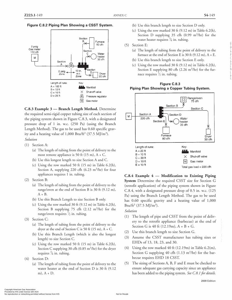
Z223.1-149 ANNEX C 54-149
2009 Edition
Figure C.8.2 Piping Plan Showing a CSST System.
C.8.3 Example 3 — Branch Length Method. Determinethe required semi-rigid copper tubing size of each section ofthe piping system shown in Figure C.8.3, with a designatedpressure drop of 1 in. w.c. (250 Pa) (using the BranchLength Method). The gas to be used has 0.60 specific grav-ity and a heating value of 1,000 Btu/ft3 (37.5 MJ/m3).Solution(1) Section A:
(a) The length of tubing from the point of delivery to themost remote appliance is 50 ft (15 m), A + C.
(b) Use this longest length to size Section A and C.(c) Using the row marked 50 ft (15 m) in Table 6.2(h),
Section A, supplying 220 cfh (6.23 m3/hr) for fourappliances requires 1 in. tubing.
(2) Section B:(a) The length of tubing from the point of delivery to the
range/oven at the end of Section B is 30 ft (9.12 m),A + B.
(b) Use this Branch Length to size Section B only.(c) Using the row marked 30 ft (9.12 m) in Table 6.2(h),
Section B supplying 75 cfh (2.12 m3/hr) for therange/oven requires 1⁄2 in. tubing.
(3) Section C:(a) The length of tubing from the point of delivery to the
dryer at the end of Section C is 50 ft (15 m), A + C.(b) Use this Branch Length (which is also the longest
length) to size Section C.(c) Using the row marked 50 ft (15 m) in Table 6.2(h),
Section C supplying 30 cfh (0.85 m3/hr) for the dryerrequires 3⁄8 in. tubing.
(4) Section D:(a) The length of tubing from the point of delivery to the
water heater at the end of Section D is 30 ft (9.12m), A + D.
(b) Use this branch length to size Section D only.(c) Using the row marked 30 ft (9.12 m) in Table 6.2(h),
Section D supplying 35 cfh (0.99 m3/hr) for thewater heater requires 3⁄8 in. tubing.
(5) Section E:(a) The length of tubing from the point of delivery to the
furnace at the end of Section E is 30 ft (9.12 m), A + E.(b) Use this branch length to size Section E only.(c) Using the row marked 30 ft (9.12 m) in Table 6.2(h),
Section E supplying 80 cfh (2.26 m3/hr) for the fur-nace requires 1⁄2 in. tubing.
Figure C.8.3Piping Plan Showing a Copper Tubing System.
C.8.4 Example 4 — Modification to Existing PipingSystem Determine the required CSST size for Section G(retrofit application) of the piping system shown in FigureC.8.4, with a designated pressure drop of 0.5 in. w.c. (125Pa) using the Branch Length Method. The gas to be usedhas 0.60 specific gravity and a heating value of 1,000Btu/ft3 (37.5 MJ/m3).Solution(1) The length of pipe and CSST from the point of deliv-
ery to the retrofit appliance (barbecue) at the end ofSection G is 40 ft (12.19m), A + B + G.
(2) Use this branch length to size Section G.(3) Assume the CSST manufacturer has tubing sizes or
EHDs of 13, 18, 23, and 30.(4) Using the row marked 40 ft (12.19m) in Table 6.2(m),
Section G supplying 40 cfh (1.13 m3/hr) for the bar-becue requires EHD 18 CSST.
(5) The sizing of Sections A, B, F and E must be checked toensure adequate gas carrying capacity since an appliancehas been added to the piping system. See C.8.1 for details.
Copyright American Gas Association Provided by IHS under license with AGA
Not for ResaleNo reproduction or networking permitted without license from IHS
--`,,```,,,,````-`-`,,`,,`,`,,`---
//^:^
^#^~
^^""
~:@
":^*^
~$~"
#:*~
::*^~
:^^#
~~#^
~:^:
@:~
*:$"
\\

Figure C.8.4Piping Plan Showing a Modification to
Existing Piping System
C.8.5 Example 5 — Calculating Pressure Drops due toTemperature Changes A test piping system is installed on awarm autumn afternoon when the temperature is 70°F(21°C). In accordance with local custom the new piping sys-tem is subjected to an air pressure test at 20 psi (140 kPa) .Overnight, the temperature drops and when the inspectorshows up first thing in the morning the temperature is 40°F(4°C).
If the volume of the piping system is unchanged, then theformula based on Boyle’s and Charles’ law for determiningthe new pressure at a reduced temperature is as follows:
where:
T1 = Initial Temperature, absolute (T1 + 459)
T2 = Final Temperature, absolute (T2 + 459)
P1 = Initial pressure, psia (P1 + 14.7)
P2 = Final pressure, psia (P2 + 14.7)
Therefore, you could expect the gauge to register 18 psiwhen the ambient temperature is 40°F (4°C).
C.8.6 Example 6 — Pressure Drop per 100 ft of PipeMethod: Using the layout shown in Fig. C.8.1 and ∆H =pressure drop, in. w.c. (27.7 in. H2O =1 psi); pipe length =ft; appliance input = Btu/hr; proceed as follows:
Notice that we interpolated the pressure drop for 111,000Btu/hr between 104,000 Btu/hr and 147,000 Btu/hr.
(4) Section 2 = 20 ft, with 135,000 Btu/hr. Here there is achoice:
For 1 in. pipe:
Notice that we interpolated the pressure drop for 135,000Btu/hr between 121,000 Btu/hr and 148,000 Btu/hr,but ignored interpolation for the ¾ in. pipe (trivial for104,000 Btu/hr to 147,000 Btu/hr).
(5) Section 3 = 30 ft, with 245,000 Btu/hr. Here there is achoice:
Notice that we ignored interpolation for these options,since the table values are close to the 245,000 Btu/hr car-ried by that section.
(6) The total pressure drop is the sum of the sectionapproaching A, Section 1, and Section 3, or either ofthe following, depending on whether we need anabsolute minimum or can accommodate the largerdrop.
Minimum Pressure Drop to farthest appliance:
For 1 in. pipe: ∆H = × 1.0 = 0.3 in. w.c.
For 1¼ in. pipe: ∆H = × 0.2 = 0.06 in. w.c.
30100
30100
(70 + 459)
(40 + 459)
(20 + 14.7)
(P2
+ 14.7)=
529
499
34.7
(P2
+ 14.7)=
P2
= 32.7-14.7
P2
= 18psig
T1
T2
P1
P2
=
∆H = × 0.2 + ( × 0.1)∆H = 0.05 in. w.c.
For ¾ in. pipe: ∆H = × 1.0 = 0.2 in. w.c.
20100
20100
14,00027,000
(1) Length to A = 20 ft, with 35,000 Btu/hr.
For ½ in. pipe: ∆H = × 0.3 = 0.06 in. w.c.
(2) Length to B = 15 ft, with 75,000 Btu/hr.
For ¾ in. pipe: ∆H = × 0.3 = 0.045 in. w.c.
(3) Section 1 = 10 ft, with 110,000 Btu/hr.Here we have a choice:
For 1 in. pipe: ∆H = × 0.2 = 0.02 in. w.c.
For ¾ in. pipe:
∆H = × 0.5 + ( × (1.0-0.5))∆H ≈ 0.06 in. w.c.
20100
15100
10100
110,000-104,000147,000-104,000
10100
54-150 NATIONAL FUEL GAS CODE Z223.1-150
2009 Edition
Copyright American Gas Association Provided by IHS under license with AGA
Not for ResaleNo reproduction or networking permitted without license from IHS
--`,,```,,,,````-`-`,,`,,`,`,,`---
//^:^^#^~^^""~:@":^*^~$~"#:*~::*^~:^^#~~#^~:^:@:~*:$"\\
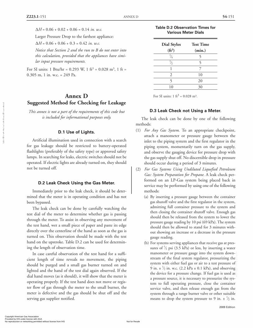
Z223.1-151 ANNEX D 54-151
2009 Edition
Larger Pressure Drop to the farthest appliance:
Notice that Section 2 and the run to B do not enter intothis calculation, provided that the appliances have simi-lar input pressure requirements.
For SI units: 1 Btu/hr = 0.293 W, 1 ft3 = 0.028 m3, 1 ft =0.305 m, 1 in. w.c. = 249 Pa.
Annex DSuggested Method for Checking for Leakage
This annex is not a part of the requirements of this code butis included for informational purposes only.
D.1 Use of Lights.
Artificial illumination used in connection with a searchfor gas leakage should be restricted to battery-operatedflashlights (preferably of the safety type) or approved safetylamps. In searching for leaks, electric switches should not beoperated. If electric lights are already turned on, they shouldnot be turned off.
D.2 Leak Check Using the Gas Meter.
Immediately prior to the leak check, it should be deter-mined that the meter is in operating condition and has notbeen bypassed.
The leak check can be done by carefully watching thetest dial of the meter to determine whether gas is passingthrough the meter. To assist in observing any movement ofthe test hand, wet a small piece of paper and paste its edgedirectly over the centerline of the hand as soon as the gas isturned on. This observation should be made with the testhand on the upstroke. Table D.2 can be used for determin-ing the length of observation time.
In case careful observation of the test hand for a suffi-cient length of time reveals no movement, the pipingshould be purged and a small gas burner turned on andlighted and the hand of the test dial again observed. If thedial hand moves (as it should), it will show that the meter isoperating properly. If the test hand does not move or regis-ter flow of gas through the meter to the small burner, themeter is defective and the gas should be shut off and theserving gas supplier notified.
Table D.2 Observation Times forVarious Meter Dials
Dial Styles Test Time(ft3) (min.)
1⁄4 51⁄2 51 72 105 2010 30
For SI units: 1 ft3 = 0.028 m3.
D.3 Leak Check not Using a Meter.
The leak check can be done by one of the followingmethods:(1) For Any Gas System. To an appropriate checkpoint,
attach a manometer or pressure gauge between theinlet to the piping system and the first regulator in thepiping system, momentarily turn on the gas supply,and observe the gauging device for pressure drop withthe gas supply shut off. No discernible drop in pressureshould occur during a period of 3 minutes.
(2) For Gas Systems Using Undiluted Liquefied PetroleumGas: System Preparation for Propane. A leak check per-formed on an LP-Gas system being placed back inservice may be performed by using one of the followingmethods:(a) By inserting a pressure gauge between the container
gas shutoff valve and the first regulator in the system,admitting full container pressure to the system andthen closing the container shutoff valve. Enough gasshould then be released from the system to lower thepressure gauge reading by 10 psi (69 kPa). The systemshould then be allowed to stand for 3 minutes with-out showing an increase or a decrease in the pressuregauge reading.
(b) For systems serving appliances that receive gas at pres-sures of 1⁄2 psi (3.5 kPa) or less, by inserting a watermanometer or pressure gauge into the system down-stream of the final system regulator, pressurizing thesystem with either fuel gas or air to a test pressure of9 in. ± 1⁄2 in. w.c. (2.2 kPa ± 0.1 kPa), and observingthe device for a pressure change. If fuel gas is used asa pressure source, it is necessary to pressurize the sys-tem to full operating pressure, close the containerservice valve, and then release enough gas from thesystem through a range burner valve or other suitablemeans to drop the system pressure to 9 in. ± 1⁄2 in.
∆H = 0.06 + 0.02 + 0.06 = 0.14 in. w.c.
∆H = 0.06 + 0.06 + 0.3 = 0.42 in. w.c.
Copyright American Gas Association Provided by IHS under license with AGA
Not for ResaleNo reproduction or networking permitted without license from IHS
--`,,```,,,,````-`-`,,`,,`,`,,`---
//^:^^#^~^^""~:@":^*^~$~"#:*~::*^~:^^#~~#^~:^:@
:~*:$"\\

54-152 NATIONAL FUEL GAS CODE Z223.1-152
2009 Edition
w.c. (2.2 kPa ± 0.1 kPa). This ensures that all regula-tors in the system are unlocked and that a leak any-where in the system is communicated to the gaugingdevice. The gauging device should indicate no loss orgain of pressure for a period of 3 minutes.
(c) By inserting a 30 psi (207 kPa) pressure gauge onthe down stream side of the first stage regulator,admitting normal operating pressure to the systemand then closing the container valve. Enough pres-sure should be released from the system to lower thepressure gauge reading by 5 psi (34.5kPa). The sys-tem should be allowed to stand for 3 minutes with-out showing an increase or a decrease in pressuregauge reading.
D.4 When Leakage is Indicated.
If the meter test hand moves or a pressure drop on the gaugeis noted, all appliances and equipment or outlets suppliedthrough the system should be examined to see if they are shutoff and do not leak. If they are found tight, there is a leak inthe piping system.
Annex ESuggested Emergency Procedure for Gas Leaks
This annex is not a part of the requirements of this code butis included for informational purposes only.
E.1
Where an investigation discloses a concentration of gasinside of a building, it is suggested the following immediateactions be taken:(1) Clear the room, building, or area of all occupants. Do
not re-enter the room, building, or area until the spacehas been determined to be safe.
(2) Use every practical means to eliminate sources of igni-tion. Take precautions to prevent smoking, strikingmatches, operating electrical switches or devices, open-ing furnace doors, and so on. If possible, cut off allelectric circuits at a remote source to eliminate opera-tion of automatic switches in the dangerous area.Safety flashlights designed for use in hazardous atmos-pheres are recommended for use in such emergencies.
(3) Notify all personnel in the area and the gas supplierfrom a telephone remote from the area of the leak.
(4) Ventilate the affected portion of the building by open-ing windows and doors.
(5) Shut off the supply of gas to the areas involved.(6) Investigate other buildings in the immediate area to
determine the presence of escaping gas therein.
Annex FFlow of Gas through Fixed Orifices
This annex is not a part of the requirements of this code butis included for informational purposes only.
F.1 Use of Orifice Tables.
F.1.1 To Check Burner Input Not Using a Meter. Gaugethe size of the burner orifice and determine flow rate at sealevel from Table F.1, Utility Gases (cubic feet per hour), orfrom Table F.2, LP-Gases (Btu per hour). When the spe-cific gravity of the utility gas is other than 0.60, select themultiplier from Table F.3 for the specific gravity of theutility gas served, and apply to the flow rate as determinedfrom Table F.1 When the altitude is above 2,000 ft (600m), first select equivalent orifice size at sea level using TableF.4, then determine flow rate from Table F.1 or Table F.2 asdirected. Having determined flow rate (as adjusted for spe-cific gravity and/or altitude where necessary), check theburner input at sea level with the manufacturer’s ratedinput.
F.1.2 To Select Correct Orifice Size for Rated BurnerInput. The selection of a fixed orifice size for any rated burn-er input is affected by many variables, including orifice coef-ficient, and it is recommended that the appliance manufac-turer be consulted for that purpose. When the correct orificesize cannot be readily determined, the orifice flow rates, asstated in the tables in this annex, can be used to select a fixedorifice size with a flow rate to approximately equal therequired rated burner input.
For gases of the specific gravity and pressure conditionsstipulated at elevations under 2,000 ft (610 m), Table F.1 (incubic feet per hour) or Table F.2 (in Btu per hour) can be useddirectly.
Where the specific gravity of the gas is other than 0.60,select the multiplier from Table F.3 for the utility gas servedand divide the rated burner input by the selected factor todetermine equivalent input at a specific gravity of 0.60; thenselect orifice size as directed above.
Where the appliance is located at an altitude of 2,000 ft(610 m) or above, first use the manufacturer’s rated input atsea level to select orifice size as directed, then use Table F.4 toselect the equivalent orifice size for use at the higher altitude.
Copyright American Gas Association Provided by IHS under license with AGA
Not for ResaleNo reproduction or networking permitted without license from IHS
--`,,```,,,,````-`-`,,`,,`,`,,`---
//^:^^#^~^^""~:@":^*^~$~"#:*~::*^~:^^#~~#^~:^:@
:~*:$"\\

Z223.1-153 ANNEX F 54-153
2009 Edition
Table F.1 Utility Gases (Cubic feet per hour at sea level)
Orifice Pressure at Orifice — (in. w.c.)or Drill
Size 3 3.5 4 5 6 7 8 9 1080 .48 .52 .55 .63 .69 .73 .79 .83 .8879 .55 .59 .64 .72 .80 .84 .90 .97 1.0178 .70 .76 .78 .88 .97 1.04 1.10 1.17 1.2477 .88 .95 .99 1.11 1.23 1.31 1.38 1.47 1.5576 1.05 1.13 1.21 1.37 1.52 1.61 1.72 1.83 1.92
75 1.16 1.25 1.34 1.52 1.64 1.79 1.91 2.04 2.1474 1.33 1.44 1.55 1.74 1.91 2.05 2.18 2.32 2.4473 1.51 1.63 1.76 1.99 2.17 2.32 2.48 2.64 2.7872 1.64 1.77 1.90 2.15 2.40 2.52 2.69 2.86 3.0071 1.82 1.97 2.06 2.33 2.54 2.73 2.91 3.11 3.26
70 2.06 2.22 2.39 2.70 2.97 3.16 3.38 3.59 3.7869 2.25 2.43 2.61 2.96 3.23 3.47 3.68 3.94 4.1468 2.52 2.72 2.93 3.26 3.58 3.88 4.14 4.41 4.6467 2.69 2.91 3.12 3.52 3.87 4.13 4.41 4.69 4.9466 2.86 3.09 3.32 3.75 4.11 4.39 4.68 4.98 5.24
65 3.14 3.39 3.72 4.28 4.62 4.84 5.16 5.50 5.7864 3.41 3.68 4.14 4.48 4.91 5.23 5.59 5.95 6.2663 3.63 3.92 4.19 4.75 5.19 5.55 5.92 6.30 6.6362 3.78 4.08 4.39 4.96 5.42 5.81 6.20 6.59 6.9461 4.02 4.34 4.66 5.27 5.77 6.15 6.57 7.00 7.37
60 4.21 4.55 4.89 5.52 5.95 6.47 6.91 7.35 7.7459 4.41 4.76 5.11 5.78 6.35 6.78 7.25 7.71 8.1158 4.66 5.03 5.39 6.10 6.68 7.13 7.62 8.11 8.5357 4.84 5.23 5.63 6.36 6.96 7.44 7.94 8.46 8.9056 5.68 6.13 6.58 7.35 8.03 8.73 9.32 9.92 10.44
55 7.11 7.68 8.22 9.30 10.18 10.85 11.59 12.34 12.9854 7.95 8.59 9.23 10.45 11.39 12.25 13.08 13.93 14.6553 9.30 10.04 10.80 12.20 13.32 14.29 15.27 16.25 17.0952 10.61 11.46 12.31 13.86 15.26 16.34 17.44 18.57 19.5351 11.82 12.77 13.69 15.47 16.97 18.16 19.40 20.64 21.71
50 12.89 13.92 14.94 16.86 18.48 19.77 21.12 22.48 23.6549 14.07 15.20 16.28 18.37 20.20 21.60 23.06 24.56 25.8348 15.15 16.36 17.62 19.88 21.81 23.31 24.90 26.51 27.8947 16.22 17.52 18.80 21.27 23.21 24.93 26.62 28.34 29.8146 17.19 18.57 19.98 22.57 24.72 26.43 28.23 30.05 31.61
45 17.73 19.15 20.52 23.10 25.36 27.18 29.03 30.90 32.5144 19.45 21.01 22.57 25.57 27.93 29.87 31.89 33.96 35.7243 20.73 22.39 24.18 27.29 29.87 32.02 34.19 36.41 38.3042 23.10 24.95 26.50 29.50 32.50 35.24 37.63 40.07 42.1441 24.06 25.98 28.15 31.69 34.81 37.17 39.70 42.27 44.46
40 25.03 27.03 29.23 33.09 36.20 38.79 41.42 44.10 46.3839 26.11 28.20 30.20 34.05 37.38 39.97 42.68 45.44 47.80
(continues)
Copyright American Gas Association Provided by IHS under license with AGA
Not for ResaleNo reproduction or networking permitted without license from IHS
--`,,```,,,,````-`-`,,`,,`,`,,`---
//^:^^#^~^^""~:@":^*^~$~"#:*~::*^~:^^#~~#^~:^:@
:~*:$"\\
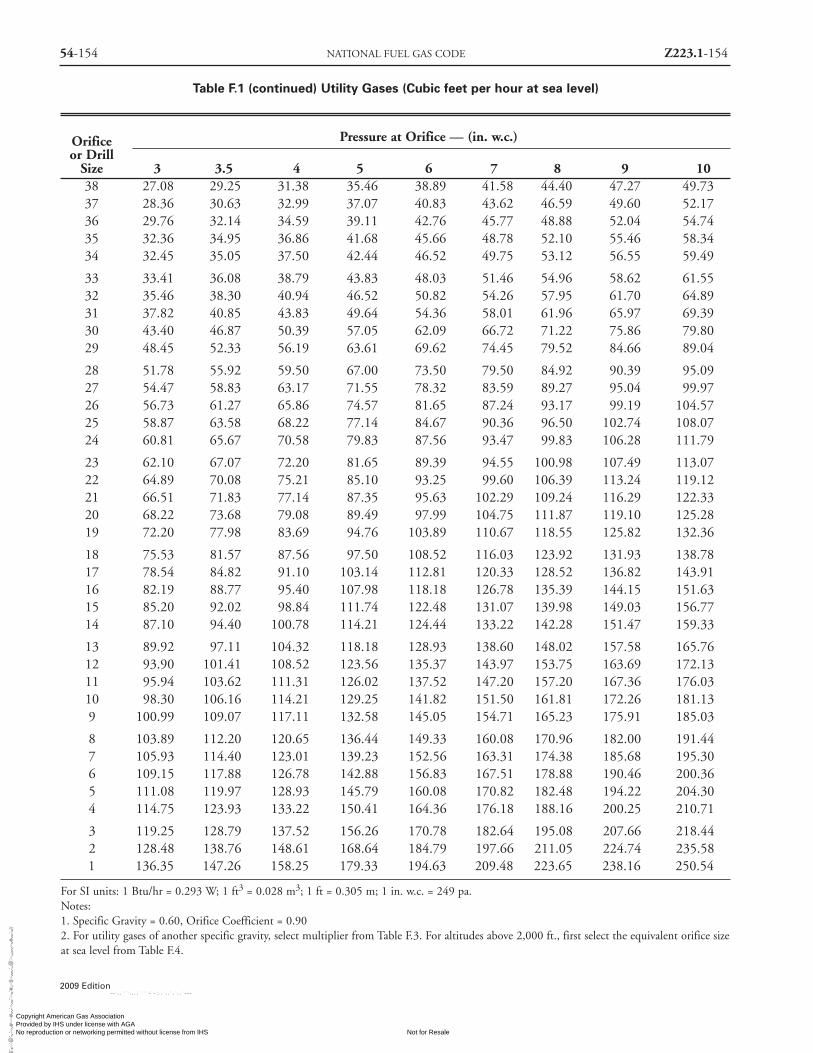
54-154 NATIONAL FUEL GAS CODE Z223.1-154
2009 Edition
Table F.1 (continued) Utility Gases (Cubic feet per hour at sea level)
Orifice Pressure at Orifice — (in. w.c.)or Drill
Size 3 3.5 4 5 6 7 8 9 1038 27.08 29.25 31.38 35.46 38.89 41.58 44.40 47.27 49.7337 28.36 30.63 32.99 37.07 40.83 43.62 46.59 49.60 52.1736 29.76 32.14 34.59 39.11 42.76 45.77 48.88 52.04 54.7435 32.36 34.95 36.86 41.68 45.66 48.78 52.10 55.46 58.3434 32.45 35.05 37.50 42.44 46.52 49.75 53.12 56.55 59.49
33 33.41 36.08 38.79 43.83 48.03 51.46 54.96 58.62 61.5532 35.46 38.30 40.94 46.52 50.82 54.26 57.95 61.70 64.8931 37.82 40.85 43.83 49.64 54.36 58.01 61.96 65.97 69.3930 43.40 46.87 50.39 57.05 62.09 66.72 71.22 75.86 79.8029 48.45 52.33 56.19 63.61 69.62 74.45 79.52 84.66 89.04
28 51.78 55.92 59.50 67.00 73.50 79.50 84.92 90.39 95.0927 54.47 58.83 63.17 71.55 78.32 83.59 89.27 95.04 99.9726 56.73 61.27 65.86 74.57 81.65 87.24 93.17 99.19 104.5725 58.87 63.58 68.22 77.14 84.67 90.36 96.50 102.74 108.0724 60.81 65.67 70.58 79.83 87.56 93.47 99.83 106.28 111.79
23 62.10 67.07 72.20 81.65 89.39 94.55 100.98 107.49 113.0722 64.89 70.08 75.21 85.10 93.25 99.60 106.39 113.24 119.1221 66.51 71.83 77.14 87.35 95.63 102.29 109.24 116.29 122.3320 68.22 73.68 79.08 89.49 97.99 104.75 111.87 119.10 125.2819 72.20 77.98 83.69 94.76 103.89 110.67 118.55 125.82 132.36
18 75.53 81.57 87.56 97.50 108.52 116.03 123.92 131.93 138.7817 78.54 84.82 91.10 103.14 112.81 120.33 128.52 136.82 143.9116 82.19 88.77 95.40 107.98 118.18 126.78 135.39 144.15 151.6315 85.20 92.02 98.84 111.74 122.48 131.07 139.98 149.03 156.7714 87.10 94.40 100.78 114.21 124.44 133.22 142.28 151.47 159.33
13 89.92 97.11 104.32 118.18 128.93 138.60 148.02 157.58 165.7612 93.90 101.41 108.52 123.56 135.37 143.97 153.75 163.69 172.1311 95.94 103.62 111.31 126.02 137.52 147.20 157.20 167.36 176.0310 98.30 106.16 114.21 129.25 141.82 151.50 161.81 172.26 181.139 100.99 109.07 117.11 132.58 145.05 154.71 165.23 175.91 185.03
8 103.89 112.20 120.65 136.44 149.33 160.08 170.96 182.00 191.447 105.93 114.40 123.01 139.23 152.56 163.31 174.38 185.68 195.306 109.15 117.88 126.78 142.88 156.83 167.51 178.88 190.46 200.365 111.08 119.97 128.93 145.79 160.08 170.82 182.48 194.22 204.304 114.75 123.93 133.22 150.41 164.36 176.18 188.16 200.25 210.71
3 119.25 128.79 137.52 156.26 170.78 182.64 195.08 207.66 218.442 128.48 138.76 148.61 168.64 184.79 197.66 211.05 224.74 235.581 136.35 147.26 158.25 179.33 194.63 209.48 223.65 238.16 250.54
For SI units: 1 Btu/hr = 0.293 W; 1 ft3 = 0.028 m3; 1 ft = 0.305 m; 1 in. w.c. = 249 pa.Notes:1. Specific Gravity = 0.60, Orifice Coefficient = 0.902. For utility gases of another specific gravity, select multiplier from Table F.3. For altitudes above 2,000 ft., first select the equivalent orifice sizeat sea level from Table F.4.
Copyright American Gas Association Provided by IHS under license with AGA
Not for ResaleNo reproduction or networking permitted without license from IHS
--`,,```,,,,````-`-`,,`,,`,`,,`---
//^:^^#^~^^""~:@":^*^~$~"#:*~::*^~:^^#~~#^~:^:@
:~*:$"\\

Z223.1-155 ANNEX F 54-155
2009 Edition
Table F.2 LP-Gases(Btu per hour at sea level)
Orifice or Drill Propane ButaneSize
0.008 519 589
0.009 656 744
0.010 812 921
0.011 981 1112
0.012 1169 1326
80 1480 1678
79 1708 1936
78 2080 2358
77 2629 2980
76 3249 3684
75 3581 4059
74 4119 4669
73 4678 5303
72 5081 5760
71 5495 6230
70 6375 7227
69 6934 7860
68 7813 8858
67 8320 9433
66 8848 10031
65 9955 11286
64 10535 11943
63 11125 12612
62 11735 13304
61 12367 14020
60 13008 14747
59 13660 15486
58 14333 16249
57 15026 17035
56 17572 19921
55 21939 24872
54 24630 27922
53 28769 32615
52 32805 37190
51 36531 41414
50 39842 45168
Table F.2 (continued) LP-Gases(Btu per hour at sea level)
Orifice or Drill Propane ButaneSize
49 43361 49157
48 46983 53263
47 50088 56783
46 53296 60420
45 54641 61944
44 60229 68280
43 64369 72973
42 71095 80599
41 74924 84940
40 78029 88459
39 80513 91215
38 83721 94912
37 87860 99605
36 92207 104532
35 98312 111454
34 100175 113566
33 103797 117672
32 109385 124007
31 117043 132689
30 134119 152046
29 150366 170466
28 160301 181728
27 168580 191114
26 175617 199092
25 181619 205896
24 187828 212935
23 192796 218567
22 200350 227131
21 205525 232997
20 210699 238863
19 223945 253880
18 233466 264673
Notes: Propane Butane1. Btu per Cubic Foot: 2516 32802. Specific Gravity: 1.50 2.013. Pressure at Orifice, inches w.c.: 11 114. Orifice Coefficient: 0.9 0.95. For altitudes above 2,000 ft (610 m), first select the equivalentorifice size at sea level from Table F.4.
Copyright American Gas Association Provided by IHS under license with AGA
Not for ResaleNo reproduction or networking permitted without license from IHS
--`,,```,,,,````-`-`,,`,,`,`,,`---
//^:^^#^~^^""~:@":^*^~$~"#:*~::*^~:^^#~~#^~:^:@
:~*:$"\\

54-156 NATIONAL FUEL GAS CODE Z223.1-156
2009 Edition
Table F.3 Multipliers for Utility Gases ofAnother Specific Gravity
Specific Multiplier Specific MultiplierGravity Gravity
0.45 1.155 0.95 0.795
0.50 1.095 1.00 0.775
0.55 1.045 1.05 0.756
0.60 1.000 1.10 0.739
0.65 0.961 1.15 0.722
0.70 0.926 1.20 0.707
0.75 0.894 1.25 0.693
0.80 0.866 1.30 0.679
0.85 0.840 1.35 0.667
0.90 0.817 1.40 0.655
Copyright American Gas Association Provided by IHS under license with AGA
Not for ResaleNo reproduction or networking permitted without license from IHS
--`,,```,,,,````-`-`,,`,,`,`,,`---
//^:^^#^~^^""~:@":^*^~$~"#:*~::*^~:^^#~~#^~:^:@
:~*:$"\\

Z223.1-157 ANNEX F 54-157
2009 Edition
Table F.4 Equivalent Orifice Sizes at High Altitudes (includes 4% input reductionfor each 1000 ft above sea level)
Orifice Orifice Size Required at Other Elevations (ft)
2000 3000 4000 5000 6000 7000 8000 9000 10,000
1 2 2 3 3 4 5 7 8 102 3 3 4 5 6 7 9 10 123 4 5 7 8 9 10 12 13 154 6 7 8 9 11 12 13 14 165 7 8 9 10 12 13 14 15 17
6 8 9 10 11 12 13 14 16 177 9 10 11 12 13 14 15 16 188 10 11 12 13 13 15 16 17 189 11 12 12 13 14 16 17 18 1910 12 13 13 14 15 16 17 18 19
11 13 13 14 15 16 17 18 19 2012 13 14 15 16 17 17 18 19 2013 15 15 16 17 18 18 19 20 2214 16 16 17 18 18 19 20 21 2315 16 17 17 18 19 20 20 22 24
16 17 18 18 19 19 20 22 23 2517 18 19 19 20 21 22 23 24 2618 19 19 20 21 22 23 24 26 2719 20 20 21 22 23 25 26 27 2820 22 22 23 24 25 26 27 28 29
21 23 23 24 25 26 27 28 28 2922 23 24 25 26 27 27 28 29 2923 25 25 26 27 27 28 29 29 3024 25 26 27 27 28 28 29 29 3025 26 27 27 28 28 29 29 30 30
26 27 28 28 28 29 29 30 30 3027 28 28 29 29 29 30 30 30 3128 29 29 29 30 30 30 30 31 3129 29 30 30 30 30 31 31 31 3230 30 31 31 31 31 32 32 33 35
31 32 32 32 33 34 35 36 37 3832 33 34 35 35 36 36 37 38 4033 35 35 36 36 37 38 38 40 4134 35 36 36 37 37 38 39 40 4235 36 36 37 37 38 39 40 41 42
36 37 38 38 39 40 41 41 42 4337 38 39 39 40 41 42 42 43 4338 39 40 41 41 42 42 43 43 4439 40 41 41 42 42 43 43 44 4440 41 42 42 42 43 43 44 44 45
For SI units: 1 ft = 0.305 m
Copyright American Gas Association Provided by IHS under license with AGA
Not for ResaleNo reproduction or networking permitted without license from IHS
--`,,```,,,,````-`-`,,`,,`,`,,`---
//^:^^#^~^^""~:@":^*^~$~"#:*~::*^~:^^#~~#^~:^:@:~*:$"\\
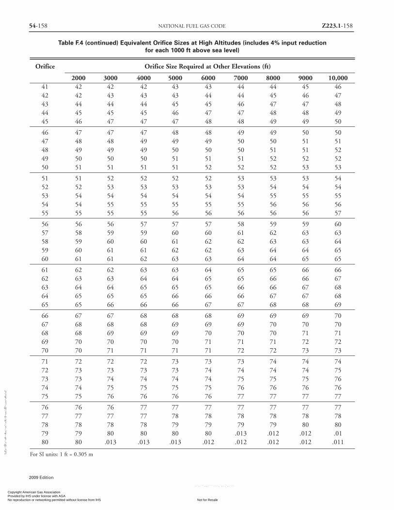
54-158 NATIONAL FUEL GAS CODE Z223.1-158
2009 Edition
Table F.4 (continued) Equivalent Orifice Sizes at High Altitudes (includes 4% input reductionfor each 1000 ft above sea level)
Orifice Orifice Size Required at Other Elevations (ft)
2000 3000 4000 5000 6000 7000 8000 9000 10,00041 42 42 42 43 43 44 44 45 4642 42 43 43 43 44 44 45 46 4743 44 44 44 45 45 46 47 47 4844 45 45 45 46 47 47 48 48 4945 46 47 47 47 48 48 49 49 50
46 47 47 47 48 48 49 49 50 5047 48 48 49 49 49 50 50 51 5148 49 49 49 50 50 50 51 51 5249 50 50 50 51 51 51 52 52 5250 51 51 51 51 52 52 52 53 53
51 51 52 52 52 52 53 53 53 5452 52 53 53 53 53 53 54 54 5453 54 54 54 54 54 54 55 55 5554 54 55 55 55 55 55 56 56 5655 55 55 55 56 56 56 56 56 57
56 56 56 57 57 57 58 59 59 6057 58 59 59 60 60 61 62 63 6358 59 60 60 61 62 62 63 63 6459 60 61 61 62 62 63 64 64 6560 61 61 62 63 63 64 64 65 65
61 62 62 63 63 64 65 65 66 6662 63 63 64 64 65 65 66 66 6763 64 64 65 65 65 66 66 67 6864 65 65 65 66 66 66 67 67 6865 65 66 66 66 67 67 68 68 69
66 67 67 68 68 68 69 69 69 7067 68 68 68 69 69 69 70 70 7068 68 69 69 69 70 70 70 71 7169 70 70 70 70 71 71 71 72 7270 70 71 71 71 71 72 72 73 73
71 72 72 72 73 73 73 74 74 7472 73 73 73 73 74 74 74 74 7573 73 74 74 74 74 75 75 75 7674 74 75 75 75 75 76 76 76 7675 75 76 76 76 76 77 77 77 77
76 76 76 77 77 77 77 77 77 7777 77 77 77 78 78 78 78 78 7878 78 78 78 79 79 79 79 80 8079 79 80 80 80 80 .013 .012 .012 .0180 80 .013 .013 .013 .012 .012 .012 .012 .011
For SI units: 1 ft = 0.305 m
Copyright American Gas Association Provided by IHS under license with AGA
Not for ResaleNo reproduction or networking permitted without license from IHS
--`,,```,,,,````-`-`,,`,,`,`,,`---
//^:^^#^~^^""~:@":^*^~$~"#:*~::*^~:^^#~~#^~:^:@
:~*:$"\\
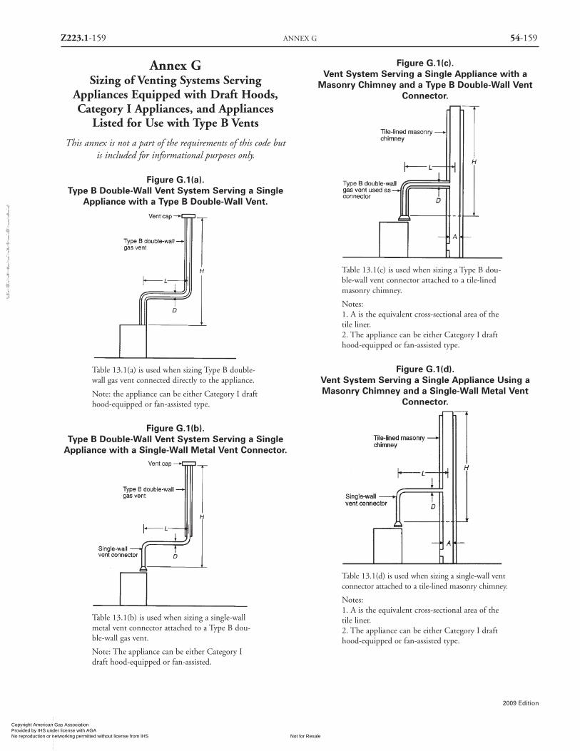
Z223.1-159 ANNEX G 54-159
2009 Edition
Annex GSizing of Venting Systems Serving
Appliances Equipped with Draft Hoods,Category I Appliances, and Appliances
Listed for Use with Type B Vents
This annex is not a part of the requirements of this code butis included for informational purposes only.
Figure G.1(a).Type B Double-Wall Vent System Serving a Single
Appliance with a Type B Double-Wall Vent.
Table 13.1(a) is used when sizing Type B double-wall gas vent connected directly to the appliance.
Note: the appliance can be either Category I drafthood-equipped or fan-assisted type.
Figure G.1(b).Type B Double-Wall Vent System Serving a SingleAppliance with a Single-Wall Metal Vent Connector.
Table 13.1(b) is used when sizing a single-wallmetal vent connector attached to a Type B dou-ble-wall gas vent.
Note: The appliance can be either Category Idraft hood-equipped or fan-assisted.
Figure G.1(c).Vent System Serving a Single Appliance with a
Masonry Chimney and a Type B Double-Wall VentConnector.
Table 13.1(c) is used when sizing a Type B dou-ble-wall vent connector attached to a tile-linedmasonry chimney.
Notes:1. A is the equivalent cross-sectional area of thetile liner.2. The appliance can be either Category I drafthood-equipped or fan-assisted type.
Figure G.1(d).Vent System Serving a Single Appliance Using aMasonry Chimney and a Single-Wall Metal Vent
Connector.
Table 13.1(d) is used when sizing a single-wall ventconnector attached to a tile-lined masonry chimney.
Notes:1. A is the equivalent cross-sectional area of thetile liner.2. The appliance can be either Category I drafthood-equipped or fan-assisted type.
Copyright American Gas Association Provided by IHS under license with AGA
Not for ResaleNo reproduction or networking permitted without license from IHS
--`,,```,,,,````-`-`,,`,,`,`,,`---
//^:^^#^~^^""~:@":^*^~$~"#:*~::*^~:^^#~~#^~:^:@
:~*:$"\\

54-160 NATIONAL FUEL GAS CODE Z223.1-160
2009 Edition
Figure G.1(e).Asbestos Cement Type B or Single-Wall Metal Vent
System Serving a Single Draft Hood-EquippedAppliance.
Asbestos cement Type B or single-wall metal ventserving a single draft hood-equipped appliance.[See Table 13.1(e).]
Figure G.1(f).Vent System Serving Two or More Appliances withType B Double-Wall Vent and Type B Double-Wall
Vent Connectors.
Table 13.2(a) is used when sizing Type B double-wall gas vent connectors attached to a Type Bdouble-wall common vent.
Note: the appliance can be either Category I drafthood-equipped or fan-assisted type.
Figure G.1(g).Vent System Serving Two or More Appliances withType B Double-Wall Vent and Single-Wall Metal Vent
Connectors.
Table 13.2(b) is used when sizing single-wall ventconnectors attached to a Type B double-wall com-mon vent.
Note: Each appliance can be either Category Idraft hood-equipped or fan-assisted type.
Figure G.1(h).Masonry Chimney Serving Two or More Appliances
with Type B Double-Wall Vent Connectors.
Table 13.2(c) is used when sizing a Type B dou-ble-wall vent connectors attached to a tile-linedmasonry chimney.
Notes:1. A is the equivalent cross-sectional area of thetile liner.2. Each appliance can be either Category I drafthood-equipped or fan-assisted type.
Copyright American Gas Association Provided by IHS under license with AGA
Not for ResaleNo reproduction or networking permitted without license from IHS
--`,,```,,,,````-`-`,,`,,`,`,,`---
//^:^
^#^~
^^""
~:@
":^*^
~$~"
#:*~
::*^~
:^^#
~~#^
~:^:
@:~
*:$"
\\

Z223.1-161 ANNEX G 54-161
2009 Edition
Figure G.1(i).Masonry Chimney Serving Two or More Appliances
with Single-Wall Metal Vent Connectors.
Table 13.2(d) is used when sizing a single-wallmetal vent connectors attached to a tile-linedmasonry chimney.
Notes:1. A is the equivalent cross-sectional area of thetile liner.2. Each appliance can be either Category I drafthood-equipped or fan-assisted type.
Figure G.1(j).Asbestos Cement Type B or Single-Wall Metal VentSystem Serving Two or More Draft Hood-Equipped
Appliances.
Asbestos cement Type B or single-wall metal pipevent serving two or more draft hood-equippedappliances. [See Table 13.2(e).]
Figure G.1(k).Use of Manifolded Common Vent Connector
Example: Manifolded common vent connectorLM can be no greater than 18 times the commonvent connector manifold inside diameter; that is,a 4 in. (100 mm) inside diameter common ventconnector manifold can not exceed 72 in.(1,800mm) in length. [See 13.2.4]
Note: This is an illustration of a typical manifold-ed vent connector. Different appliance, vent con-nector, or common vent types are possible. SeeSection 13.2.
Figure G.1(l).Use of Offset Common Vent.
Note: This is an illustration of a typical offsetvent. Different appliance, vent connector, or venttypes are possible. [See Sections 13.1.and 13.2.]
Copyright American Gas Association Provided by IHS under license with AGA
Not for ResaleNo reproduction or networking permitted without license from IHS
--`,,```,,,,````-`-`,,`,,`,`,,`---
//^:^^#^~^^""~:@":^*^~$~"#:*~::*^~:^^#~~#^~:^:@
:~*:$"\\

54-162 NATIONAL FUEL GAS CODE Z223.1-162
2009 Edition
Figure G.1(m)Multistory Gas Vent Design Procedure for
Each Segment of System.
Mulyistory gas vent design procedure for each segmentof system
Figure G.1(n).Principles of Design of Multistory Vents Using Vent
Connector and Common Vent Design Tables.[See 13.2.14 through 13.2.17.]
G.1 Examples UsingSingle Appliance Venting Tables.
See Figures G.1(a) through G.1(e).
G.1.1 Example 1: Single Draft Hood-EquippedAppliance An installer has a 120,000 Btu/hr input appli-ance with a 5 in. diameter draft hood outlet that needs to bevented into a 10 ft high Type B vent system. What size ventshould be used assuming (1) a 5 ft lateral single-wall metalvent connector is used with two 90 degree elbows, or (2) a 5ft lateral single-wall metal vent connector is used with three90 degree elbows in the vent system? See Figure G.1.1.
Vent connector sizedepends on:• Input• Rise• Available total height H• Table 13.2(a) connectors
Common vent sizedepends on:• Combined inputs• Available total height H• Table 13.2(a) commonvent
Copyright American Gas Association Provided by IHS under license with AGA
Not for ResaleNo reproduction or networking permitted without license from IHS
--`,,```,,,,````-`-`,,`,,`,`,,`---
//^:^
^#^~
^^""
~:@
":^*^
~$~"
#:*~
::*^~
:^^#
~~#^
~:^:
@:~
*:$"
\\

Z223.1-163 ANNEX G 54-163
2009 Edition
Figure G.1.1.Single Draft Hood-Equipped Appliance (Example 1).
Solution
Table 13.1(b) should be used to solve this problem,
because single-wall metal vent connectors are being used
with a Type B vent.
(1) Read down the first column in Table 13.1(b) until the
row associated with a 10 ft height and 5 ft lateral is
found. Read across this row until a vent capacity greater
than 120,000 Btu/hr is located in the shaded columns
labeled NAT Max for draft hood-equipped appliances.
In this case, a 5 in. diameter vent has a capacity of
122,000 Btu/hr and can be used for this application.
(2) If three 90 degree elbows are used in the vent system,
then the maximum vent capacity listed in the tables
must be reduced by 10 percent [see 13.1.3]. This
implies that the 5 in. diameter vent has an adjusted
capacity of only 110,000 Btu/hr. In this case, the vent
system must be increased to 6 in. in diameter. See the
following calculations:
122,000 × .90 = 110,000 for 5 in. vent
From Table 13.1(b), select 6 in. vent
186,000 × .90 = 167,000
This is greater than the required 120,000. Therefore, use
a 6 in. vent and connector where three elbows are used.
G.1.2 Example 2: Single Fan-Assisted Appliance An
installer has an 80,000 Btu/hr input fan-assisted appliance
that must be installed using 10 ft of lateral connector
attached to a 30 ft high Type B vent. Two 90 degree elbows
are needed for the installation. Can a single-wall metal vent
connector be used for this application? See Figure G.1.2.
Figure G.1.2.Single Fan-Assisted Appliance (Example 2).
SolutionTable 13.1(b) refers to the use of single-wall metal vent
connectors withType B vent. In the first column find the rowassociated with a 30 ft height and a 10 ft lateral. Read acrossthis row, looking at the FAN Min and FAN Max columns, tofind that a 3 in. diameter single-wall metal vent connector isnot recommended. Moving to the next larger size single wallconnector (4 in.), we find that a 4 in. diameter single-wallmetal connector has a recommended minimum vent capaci-ty of 91,000 Btu/hr and a recommended maximum ventcapacity of 144,000 Btu/hr. The 80,000 Btu/hr fan-assistedappliance is outside this range, so the conclusion is that a sin-gle-wall metal vent connector cannot be used to vent thisappliance using 10 ft of lateral for the connector.
However, if the 80,000 Btu/hr input appliance could bemoved to within 5 ft of the vertical vent, then a 4 in. single-wall metal connector could be used to vent the appliance.Table 13.1(b) shows the acceptable range of vent capacitiesfor a 4 in. vent with 5 ft of lateral to be between 72,000Btu/hr and 157,000 Btu/hr.
If the appliance cannot be moved closer to the verticalvent, then Type B vent could be used as the connector mate-rial. In this case, Table 13.1(a) shows that, for a 30 ft highvent with 10 ft of lateral, the acceptable range of vent capac-ities for a 4 in. diameter vent attached to a fan-assistedappliance is between 37,000 Btu/hr and 150,000 Btu/hr.
G.1.3 Example 3: Interpolating Between Table Values Aninstaller has an 80,000 Btu/hr input appliance with a 4 in.diameter draft hood outlet that needs to be vented into a 12ft high Type B vent. The vent connector has a 5 ft laterallength and is also Type B. Can this appliance be ventedusing a 4 in. diameter vent?
SolutionTable 13.1(a) is used in the case of an all Type B vent sys-
Copyright American Gas Association Provided by IHS under license with AGA
Not for ResaleNo reproduction or networking permitted without license from IHS
--`,,```,,,,````-`-`,,`,,`,`,,`---
//^:^^#^~^^""~:@":^*^~$~"#:*~::*^~:^^#~~#^~:^:@:~*:$"\\

54-164 NATIONAL FUEL GAS CODE Z223.1-164
2009 Edition
tem. However, since there is no entry in Table 13.1(a) for aheight of 12 ft, interpolation must be used. Read down the 4in. diameter NAT Max column to the row associated with 10ft height and 5 ft lateral to find the capacity value of 77,000Btu/hr. Read further down to the 15 ft height, 5 ft lateral rowto find the capacity value of 87,000 Btu/hr. The differencebetween the 15 ft height capacity value and the 10 ft heightcapacity value is 10,000 Btu/hr. The capacity for a vent systemwith a 12 ft height is equal to the capacity for a 10 ft heightplus 2⁄5 of the difference between the 10 ft and 15 ft heightvalues, or 77,000 + 2⁄5 × 10,000 = 81,000 Btu/hr. Therefore,a 4 in. diameter vent may be used in the installation.
G.2 Examples Using Common Venting Tables.See Figures G.1(f ) through G.1(n).
G.2.1 Example 4: Common Venting Two Draft Hood-Equipped Appliances A 35,000 Btu/hr water heater is to becommon vented with a 150,000 Btu/hr furnace, using acommon vent with a total height of 30 ft. The connector riseis 2 ft for the water heater with a horizontal length of 4 ft.The connector rise for the furnace is 3 ft with a horizontallength of 8 ft. Assume single-wall metal connectors will beused with Type B vent. What size connectors and combinedvent should be used in this installation? See Figure G.2.1.
Figure G.2.1.Common Venting Two Draft Hood-Equipped
Appliances (Example 4).
SolutionTable 13.2(b) should be used to size single-wall metal vent
connectors attached to Type B vertical vents. In the vent con-nector capacity portion of Table 13.2(b), find the row associ-ated with a 30 ft vent height. For a 2 ft rise on the vent con-nector for the water heater, read the shaded columns for drafthood-equipped appliances to find that a 3 in. diameter ventconnector has a capacity of 37,000 Btu/hr. Therefore, a 3 in.single-wall metal vent connector can be used with the water
heater. For a draft hood-equipped furnace with a 3 ft rise,read across the appropriate row to find that a 5 in. diametervent connector has a maximum capacity of 120,000 Btu/hr(which is too small for the furnace) and a 6 in. diameter ventconnector has a maximum vent capacity of 172,000 Btu/hr.Therefore, a 6 in. diameter vent connector should be usedwith the 150,000 Btu/hr furnace. Since both vent connectorhorizontal lengths are less than the maximum lengths listedin 13.2.2, the table values can be used without adjustments.
In the common vent capacity portion of Table 13.2(b),find the row associated with a 30 ft vent height and readover to the NAT + NAT portion of the 6 in. diameter col-umn to find a maximum combined capacity of 257,000Btu/hr. Since the two appliances total only 185,000 Btu/hr,a 6 in. common vent can be used.
G.2.2 Example 5 (a): Common Venting a Draft Hood-Equipped Water Heater with a Fan-Assisted Furnaceinto a Type B Vent. In this case, a 35,000 Btu/hr inputdraft hood-equipped water heater with a 4 in. diameterdraft hood outlet, 2 ft of connector rise, and 4 ft of hori-zontal length is to be common vented with a 100,000Btu/hr fan-assisted furnace with a 4 in. diameter flue collar,3 ft of connector rise, and 6 ft of horizontal length. Thecommon vent consists of a 30 ft height of Type B vent.What are the recommended vent diameters for each con-nector and the common vent? The installer would like touse a single-wall metal vent connector. See Figure G.2.2.
Figure G.2.2.Common Venting a Draft Hood-Equipped WaterHeater with a Fan-Assisted Furnace into a Type B
Double-Wall Common Vent [Example 5 (a)].
Solution (See Table 13.2(b))
Water Heater Vent Connector Diameter. Since the waterheater vent connector horizontal length of 4 ft is less thanthe maximum value listed in Table 13.2(b), the ventingtable values can be used without adjustments. Using theVent Connector Capacity portion of Table 13.2(b), read
Copyright American Gas Association Provided by IHS under license with AGA
Not for ResaleNo reproduction or networking permitted without license from IHS
--`,,```,,,,````-`-`,,`,,`,`,,`---
//^:^^#^~^^""~:@":^*^~$~"#:*~::*^~:^^#~~#^~:^:@:~*:$"\\

Z223.1-165 ANNEX G 54-165
2009 Edition
down the Total Vent Height (H) column to 30 ft and readacross the 2 ft Connector Rise (R) row to the first Btu/hrrating in the NAT Max column that is equal to or greaterthan the water heater input rating. The table shows that a 3in. vent connector has a maximum input rating of 37,000Btu/hr. Although this rating is greater than the water heaterinput rating, a 3 in. vent connector is prohibited by13.2.24. A 4 in. vent connector has a maximum input rat-ing of 67,000 Btu/hr and is equal to the draft hood outletdiameter. A 4 in. vent connector is selected. Since the waterheater is equipped with a draft hood, there are no minimuminput rating restrictions.
Furnace Vent Connector Diameter. Using the VentConnector Capacity portion of Table 13.2(b), read downthe Total Vent Height (H) column to 30 ft and across the 3ft Connector Rise (R) row. Since the furnace has a fan-assist-ed combustion system, find the first FAN Max column witha Btu/hr rating greater than the furnace input rating. The 4in. vent connector has a maximum input rating of 119,000Btu/hr and a minimum input rating of 85,000 Btu/hr.
The 100,000 Btu/hr furnace in this example falls withinthis range, so a 4 in. connector is adequate. Since the fur-nace vent connector horizontal length of 6 ft is less than themaximum value listed in 13.2.2, the venting table valuescan be used without adjustment. If the furnace had an inputrating of 80,000 Btu/hr, then a Type B vent connector [seeTable 13.2(a)] would be needed in order to meet the mini-mum capacity limit.
Common Vent Diameter. The total input to the commonvent is 135,000 Btu/hr. Using the Common Vent Capacityportion of Table 13.2(b), read down the Total Vent Height(H) column to 30 ft and across this row to find the smallestvent diameter in the FAN + NAT column that has a Btu/hrrating equal to or greater than 135,000 Btu/hr. The 4 in.common vent has a capacity of 132,000 Btu/hr and the 5 in.common vent has a capacity of 202,000 Btu/hr. Therefore,the 5 in. common vent should be used in this example.
Summary. In this example, the installer can use a 4 in.diameter, single-wall metal vent connector for the waterheater and a 4 in. diameter, single-wall metal vent connec-tor for the furnace. The common vent should be a 5 in.diameter Type B vent.
G.2.3 Example 5 (b): Common Venting Into anInterior Masonry Chimney. In this case, the water heaterand fan-assisted furnace of Example 5 (a) are to be commonvented into a clay-tile-lined masonry chimney with a 30 ftheight. The chimney is not exposed to the outdoors belowthe roof line. The internal dimensions of the clay tile linerare nominally 8 in. × 12 in. Assuming the same vent con-
nector heights, laterals, and materials found in Example 5(a), what are the recommended vent connector diameters,and is this an acceptable installation?Solution
Table 13.2(d) is used to size common venting installationsinvolving single-wall connectors into masonry chimneys.
Water Heater Vent Connector Diameter. Using Table13.2(d), Vent Connector Capacity, read down the TotalVent Height (H) column to 30 ft, and read across the 2 ftConnector Rise (R) row to the first Btu/hr rating in theNAT Max column that is equal to or greater than the waterheater input rating. The table shows that a 3 in. vent con-nector has a maximum input of only 31,000 Btu/hr, whilea 4 in. vent connector has a maximum input of 57,000Btu/hr. A 4 in. vent connector must therefore be used.
Furnace Vent Connector Diameter. Using the VentConnector Capacity portion of Table 13.2(d), read downthe Total Vent Height (H) column to 30 ft and across the 3ft Connector Rise (R) row. Because the furnace has a fan-assisted combustion system, find the first FAN Max columnwith a Btu/hr rating greater than the furnace input rating.The 4 in. vent connector has a maximum input rating of127,000 Btu/hr and a minimum input rating of 95,000Btu/hr. The 100,000 Btu/hr furnace in this example fallswithin this range, so a 4 in. connector is adequate.
Masonry Chimney. From Table G.2.3, the EquivalentArea for a Nominal Liner size of 8 in. × 12 in. is 63.6 in.2.Using Table 13.2(d), Common Vent Capacity, read downthe FAN + NAT column under the Minimum Internal Areaof Chimney value of 63 to the row for 30 ft height to finda capacity value of 739,000 Btu/hr. The combined inputrating of the furnace and water heater, 135,000 Btu/hr, isless than the table value, so this is an acceptable installation.
Section 13.2.18 requires the common vent area to be nogreater than seven times the smallest listed appliance catego-rized vent area, flue collar area, or draft hood outlet area. Bothappliances in this installation have 4 in. diameter outlets.From Table G.2.3, the equivalent area for an inside diameterof 4 in. is 12.2 in.2. Seven times 12.2 equals 85.4, which isgreater than 63.6, so this configuration is acceptable.
G.2.4 Example 5 (c): Common Venting into an ExteriorMasonry Chimney. In this case, the water heater and fan-assisted furnace of Examples 5 (a) and 5 (b) are to be com-mon vented into an exterior masonry chimney. The chim-ney height, clay-tile-liner dimensions, and vent connectorheights and laterals are the same as in Example 5 (b). Thissystem is being installed in Charlotte, North Carolina. Doesthis exterior masonry chimney need to be relined? If so,what corrugated metallic liner size is recommended? What
Copyright American Gas Association Provided by IHS under license with AGA
Not for ResaleNo reproduction or networking permitted without license from IHS
--`,,```,,,,````-`-`,,`,,`,`,,`---
//^:^^#^~^^""~:@":^*^~$~"#:*~::*^~:^^#~~#^~:^:@
:~*:$"\\

54-166 NATIONAL FUEL GAS CODE Z223.1-166
2009 Edition
vent connector diameters are recommended? See TableG.2.3 and Figure G.2.4.
Table G.2.3 Masonry Chimney Liner Dimensionswith Circular Equivalents
InsideInside Diameter
Nominal Dimensions or Equivalent EquivalentLiner Size of Liner Diameter Area
(in.) (in.) (in.) (in.2)
4 × 8 2 1⁄2 × 6 1⁄2 4.0 12.25.0 19.66.0 28.37.0 38.3
8 × 8 6 3⁄4 × 6 3⁄4 7.4 42.78.0 50.3
8 × 12 6 1⁄2 × 10 1⁄2 9.0 63.610.0 78.5
12 × 12 9 3⁄4 × 9 3⁄4 10.4 83.311.0 95.0
12 × 16 9 1⁄2 × 13 1⁄2 11.8 107.512.0 113.014.0 153.9
16 × 16 13 1⁄4 × 13 1⁄4 14.5 162.915.0 176.7
16 × 20 13 × 17 16.2 206.118.0 254.4
20 × 20 16 3⁄4 × 16 3⁄4 18.2 260.220.0 314.1
20 × 24 16 1⁄2 × 20 1⁄2 20.1 314.222.0 380.1
24 × 24 20 1⁄4 × 20 1⁄4 22.1 380.124.0 452.3
24 × 28 20 1⁄4 × 24 1⁄4 24.1 456.228 × 28 24 1⁄4 × 24 1⁄4 26.4 543.3
27.0 572.530 × 30 25 1⁄2 × 25 1⁄2 27.9 607.0
30.0 706.830 × 36 25 1⁄2 × 31 1⁄2 30.9 749.9
33.0 855.336 × 36 31 1⁄2 × 31 1⁄2 34.4 929.4
36.0 1017.9
For SI units: 1 in. = 25.4 mm; 1 in.2 = 645 mm2.Note: When liner sizes differ dimensionally from those shown inTable G.2.3, equivalent diameters may be determined from pub-lished tables for square and rectangular ducts of equivalent carryingcapacity or by other engineering methods.
SolutionAccording to 13.2.22, Type B vent connectors are
required to be used with exterior masonry chimneys. UseTable 13.2(h) and Table 13.2(i) to size FAN+NAT common
venting installations involving Type-B double wall connec-tors into exterior masonry chimneys.
The local 99 percent winter design temperature neededto use Table 13.2(h) and Table 13.2(i) can be found inASHRAE Handbook — Fundamentals. For Charlotte, NorthCarolina, this design temperature is 19°F.
Chimney Liner Requirement. As in Example 5 (b), use the63 in.2 Internal Area columns for this size clay tile liner.Read down the 63 in.2 column of Table 13.2(h) to the 30 ftheight row to find that the Combined Appliance MaximumInput is 747,000 Btu/hr. The combined input rating of theappliances in this installation, 135,000 Btu/hr, is less thanthe maximum value, so this criterion is satisfied. Table13.2(i), at a 19°F Design Temperature, and at the same VentHeight and Internal Area used earlier, shows that the mini-mum allowable input rating of a space-heating appliance is470,000 Btu/hr. The furnace input rating of 100,000Btu/hr is less than this minimum value. So this criterion isnot satisfied, and an alternative venting design needs to beused, such as a Type B vent shown in Example 5 (a) or a list-ed chimney liner system shown in the remainder of theexample.
According to 13.2.20, Table 13.2(a) or Table 13.2(b) areused for sizing corrugated metallic liners in masonry chim-neys, with the maximum common vent capacities reducedby 20 percent. This example will be continued assumingType B vent connectors.
Water Heater Vent Connector Diameter. Using Table13.2(a), Vent Connector Capacity, read down the Total VentHeight (H) column to 30 ft, and read across the 2 ftConnector Rise (R) row to the first Btu/hr rating in the NATMax column that is equal to or greater than the water heaterinput rating. The table shows that a 3 in. vent connector hasa maximum capacity of 39,000 Btu/hr. Although this ratingis greater than the water heater input rating, a 3 in. vent con-nector is prohibited by 13.2.24. A 4 in. vent connector has amaximum input rating of 70,000 Btu/hr and is equal to thedraft hood outlet diameter. A 4 in. vent connector is selected.
Furnace Vent Connector Diameter. Using Table 13.2(a),Vent Connector Capacity, read down the Total Vent Height(H) column to 30 ft, and read across the 3 ft ConnectorRise (R) row to the first Btu/hr rating in the FAN Max col-umn that is equal to or greater than the furnace input rat-ing. The 100,000 Btu/hr furnace in this example falls with-in this range, so a 4 in. connector is adequate.
Chimney Liner Diameter. The total input to the commonvent is 135,000 Btu/hr. Using the Common Vent CapacityPortion of Table 13.2(a), read down the Total Vent Height(H) column to 30 ft and across this row to find the smallestvent diameter in the FAN+NAT column that has a Btu/hr
Copyright American Gas Association Provided by IHS under license with AGA
Not for ResaleNo reproduction or networking permitted without license from IHS
--`,,```,,,,````-`-`,,`,,`,`,,`---
//^:^^#^~^^""~:@":^*^~$~"#:*~::*^~:^^#~~#^~:^:@
:~*:$"\\

Z223.1-167 ANNEX H 54-167
2009 Edition
rating greater than 135,000 Btu/hr. The 4 in. common venthas a capacity of 138,000 Btu/hr. Reducing the maximumcapacity by 20 percent (13.2.20) results in a maximumcapacity for a 4 in. corrugated liner of 110,000 Btu/hr, lessthan the total input of 135,000 Btu/hr. So a larger liner isneeded. The 5 in. common vent capacity listed in Table13.2(a) is 210,000 Btu/hr, and after reducing by 20 percentis 168,000 Btu/hr. Therefore, a 5 in. corrugated metal linershould be used in this example.
Single Wall Connectors. Once it has been established thatrelining the chimney is necessary, Type B double-wall ventconnectors are not specifically required. This example couldbe redone using Table 13.2(b) for single wall vent connectors.For this case, the vent connector and liner diameters would bethe same as found above with Type B double wall connectors.
Annex HRecommended Procedure for
Safety Inspection of an ExistingAppliance Installation
This annex is not a part of the requirements of this codebut is included for informational purposes only.
H.1 General.
The following procedure is intended as a guide to aid indetermining that an appliance is properly installed and is ina safe condition for continuing use.
This procedure is intended for central furnace and boilerinstallations, and may not be applicable to all installations.This procedure should be performed prior to any attempt
Figure G.2.4.A range of Winter Design Temperatures Used in Analyzing Exterior Masonry Chimneys in the United States.
99% Winter Design Temperatures for the Contiguous United States
This map is a necessarily generalized guide to temperatures in the contiguous United States. Temperatures shown for areas such as mountainousregions and large urban centers are not necessarily accurate. The data used to develop this map are from the 1993 ASHRAE Handbook —Fundamentals (Chapter 24, Table 1: climate Conditions for the United States).
For 99% winter design temperature in Alaska, consult the ASHRAE Handbook — Fundamentals.
99% winter design temperature for Hawaii are greater than 37°F.
Copyright American Gas Association Provided by IHS under license with AGA
Not for ResaleNo reproduction or networking permitted without license from IHS
--`,,```,,,,````-`-`,,`,,`,`,,`---
//^:^^#^~^^""~:@":^*^~$~"#:*~::*^~:^^#~~#^~:^:@:~*:$"\\
54-168 NATIONAL FUEL GAS CODE Z223.1-168
2009 Edition
to modify the appliance or the installation. If it is deter-mined a condition that could result in unsafe operationexists, shut off the appliance and advise the owner of theunsafe condition.
The following steps should be followed in making thesafety inspection:(1) Conduct a test for gas leakage. [See 8.2](2) Visually inspect the venting system for proper size and
horizontal pitch, and determine that there is no block-age, restriction, leakage, corrosion, or other deficien-cies that could cause an unsafe condition.
(3) Shut off all gas to the appliance, and shut off any otherfuel gas burning appliance within the same room. Usethe shutoff valve in the supply line to each appliance.
(4) Inspect burners and crossovers for blockage and corro-sion.
(5) Furnace Installations. Inspect the heat exchanger forcracks, openings, or excessive corrosion.
(6) Boiler Installations. Inspect for evidence of water orcombustion product leaks.
(7) Close all building doors and windows and all doorsbetween the space in which the appliance is locatedand other spaces of the building that can be closed.Turn on any clothes dryers. Turn on any exhaust fans,such as range hoods and bathroom exhausts, so theywill operate at maximum speed. Do not operate a sum-mer exhaust fan. Close fireplace dampers. If, aftercompleting Steps 8 through 13, it is believed sufficientcombustion air is not available, refer to Section 9.3 ofthis code.
(8) Place the appliance being inspected in operation.Follow the lighting instructions. Adjust the thermostatso the appliance will operate continuously.
(9) Determine that the pilot(s), where provided, is burningproperly and that the main burner ignition is satisfac-tory, by interrupting and re-establishing the electricalsupply to the appliance in any convenient manner. Ifthe appliance is equipped with a continuous pilot(s),test all pilot safety device(s) to determine whether it isoperating properly by extinguishing the pilot(s) whenthe main burner(s) is off and determining, after 3 min-utes, that the main burner gas does not flow upon a callfor heat. If the appliance is not provided with a pilot(s),test for proper operation of the ignition system inaccordance with the appliance manufacturer's lightingand operating instructions.
(10) Visually determine that the main burner gas is burningproperly (i.e., no floating, lifting, or flashback). Adjustthe primary air shutters as required. If the appliance isequipped with high and low flame controlling or flame
modulation, check for proper main burner operationat low flame.
(11) Test for spillage at the draft hood relief opening after 5minutes of main burner operation. Use the flame of amatch or candle or smoke. (See section 11.6)
(12) Turn on all other fuel gas burning appliances withinthe same room so they will operate at their full inputs.Follow lighting instructions for each appliance.
(13) Repeat Steps 10 and 11 on the appliance beinginspected.
(14) Return doors, windows, exhaust fans, fireplacedampers, and any other fuel gas burning appliance totheir previous conditions of use.
(15) Furnace Installations. Check both the limit control andthe fan control for proper operation. Limit controloperation can be checked by blocking the circulatingair inlet or temporarily disconnecting the electricalsupply to the blower motor and determining that thelimit control acts to shut off the main burner gas.
(16) Boiler Installations. Verify that the water pumps are inoperating condition. Test low water cutoffs, automaticfeed controls, pressure and temperature limit controls,and relief valves in accordance with the manufacturer’srecommendations to determine that they are in oper-ating condition.
Annex IIndoor Combustion Air Calculation
ExamplesThis annex is not a part of the requirements of this code
but is included for informational purposes only.
I.1 New Installation.
Determine if the indoor volume is sufficient to supplycombustion air for the following new installation example.
Example Installation 1: A 100,000 Btu/hr fan-assisted fur-nace and a 40,000 Btu/hr draft hood equipped water heateris being installed in a basement of a new single family home.The basement measures 25 ft × 40 ft with an 8 ft ceiling.
Solution(1) Determine the total required volume: Since the air
infiltration rate is unknown, the standard method todetermine combustion air is used to calculate therequired volume.(a) The combined input for the appliances located in the
Copyright American Gas Association Provided by IHS under license with AGA
Not for ResaleNo reproduction or networking permitted without license from IHS
--`,,```,,,,````-`-`,,`,,`,`,,`---
//^:^
^#^~
^^""
~:@
":^*^
~$~"
#:*~
::*^~
:^^#
~~#^
~:^:
@:~
*:$"
\\

Z223.1-169 ANNEX I 54-169
2009 Edition
basement is calculated as follows:100,000 Btu/hr + 40,000 Btu/hr = 140,000 Btu/hr.
(b) The Standard Method requires that the required vol-ume be determined based on 50 cubic ft per 1,000Btu/hr.
(c) Using Table A.9.3.2.1, the required volume for the140,000 Btu/hr combined input is 7,000 ft3
(2) Determine available volume: The available volume isthe total basement volume:Available Volume: 25 ft × 40 ft × 8 ft ceiling = 8,000 ft3
Conclusion: The installation can use indoor air because theavailable volume of 8,000 ft3 exceeds the total required vol-ume of 7,000 ft3. No outdoor air openings are required.
I.2 New Installation, KnownAir Infiltration Rate Method.
Determine if the indoor volume is sufficient to supplycombustion air for the following new installation example.
Example Installation 2: A 100,000 Btu/hr fan-assisted fur-nace and a 40,000 Btu/hr draft hood equipped water heaterwill be installed in a new single family house. It was deter-mined (either by use of the ASHRAE calculation method orblower door test) that the house will have 0.65 air changesper hour. The furnace and water heater will be installed in a20 ft × 35 ft basement with an 8 ft ceiling height.
Solution(1) Determine the required volume: Because two types of
appliances are located in the space, a fan-assisted furnaceand a draft hood equipped water heater, the required vol-ume must be determined for each appliance and thencombined to determine the total required volume:(a) Fan-assisted furnace: For structures that the air infil-
tration rate is known, section 9.3.2.2 permits the useof the Equation in 9.3.2.2 (2) to determine therequired volume for a fan-assisted appliance. Section9.3.2.2 (3) limits the use of the equation to air changerates equal to or less than 0.60 ACH. While the housewas determined to have a 0.65 ACH, 0.60 is used tocalculate the required volume. Using the equation in9.3.2.2 (2), the required volume for a 100,000 Btu/hrfan-assisted furnace is calculated as follows:
(b) Draft-hood equipped water heater: For structuresthat the air infiltration rate is known, section 9.3.2.2permits the use of the equation in 9.3.2.2 (1) to
determine the required volume for a draft hoodequipped appliance. Section 9.3.2.2 (3) limits the useof the equation to air change rates equal to or lessthan 0.60 ACH. While the house was determined tohave a 0.65 ACH, 0.60 is used to calculate therequired volume. Using the equation in 9.3.2.2 (1),the required volume for the 40,000 Btu/hr waterheater is calculated as follows:
(c) Total required volume: Section 9.3.2 states that thetotal required volume of indoor air is the sum of therequired volumes for all appliances located in thespace.
2,500 ft3+ 1,400 ft3
= 3,900 ft3
(2) The available volume [is determine as follows]:(20 ft × 35 ft) × 8 ft = 5,600 ft3
Conclusion: The installation can use indoor air because theavailable volume of 5,600 ft3 exceeds the total required vol-ume of 3,900 ft3. No outdoor air openings are required.
I.3 New Installation, KnownAir Infiltration Rate Method.
Determine if the indoor volume is sufficient to supplycombustion air for the following new installation example.
Example Installation 3: A 100,000 Btu/hr fan-assisted fur-nace and a 40,000 Btu/hr draft hood equipped water heaterwill be installed in a new single family house. It was deter-mined (either by use of the ASHRAE calculation method orblower door test) that the house will have 0.30 air changesper hour. The furnace and water heater will be installed in a20 ft × 35 ft basement with an 8 ft ceiling height.
Solution(1) Determine the required volume: Because two types of
appliances are located in the space, a fan-assisted furnaceand a draft hood equipped water heater, the requiredvolume must be determined for each appliance and thencombined to determine the total required volume:(a) Fan-assisted furnace: For structures that the air infiltra-
tion rate is known, section 9.3.2.2 permits the use ofthe equation in 9.3.2.2 (2) to determine the requiredvolume for a fan-assisted appliance. Section 9.3.2.2 (3)limits the use of the equation to air change rates equalto or less than 0.60 ACH. Because 0.30 ACH is lessthan 0.60 ACH, 0.30 ACH can be used to calculate
Copyright American Gas Association Provided by IHS under license with AGA
Not for ResaleNo reproduction or networking permitted without license from IHS
--`,,```,,,,````-`-`,,`,,`,`,,`---
//^:^^#^~^^""~:@":^*^~$~"#:*~::*^~:^^#~~#^~:^:@:~*:$"\\

54-170 NATIONAL FUEL GAS CODE Z223.1-170
2009 Edition
the required volume. Using the equation in 9.3.2.2 (2),the required volume for a 100,000 Btu/hr fan-assistedfurnace is calculated as follows:
(b) Draft hood equipped water heater: For structures thatthe air infiltration rate is known, section 9.3.2.2 per-mits the use of the equation 9.3.2.2 (1) to determinethe required volume for a draft hood equipped appli-ance. Section 9.3.2.2 (3) limits the use of the equationto air change rates equal to or less than 0.60 ACH.Because 0.30 ACH is less than 0.60 ACH, 0.30 ACHcan be used to calculate the required volume. UsingEquation 9.3.2.2 (1), the required volume for the40,000 Btu/hr water heater is calculated as follows:
(c) Total required volume: Section 9.3.2 states that thetotal required volume of indoor air is the sum of therequired volumes for all appliances located in thespace.
5,000 ft3+ 2,800 ft3
= 7,800 ft3
(2) The available volume [is determine as follows]:
(20 ft × 35 ft) × 8 ft = 5,600 ft3
Conclusion: The installation can not use indoor airalone, because the available volume of 5,600 ft3 is lessthan the total required volume of 7,800 ft3. Outdoorair openings can be sized in accordance with all airfrom the outdoors [see 9.3.3] or by use of the combi-nation of indoor/outdoor air method [see 9.3.4].
Annex JExample of Combination of
Indoor and Outdoor Combustion andVentilation Opening Design.
This annex is not a part of the requirements of this code butis included for informational purposes only.
J.1 Example of Combination Indoor andOutdoor Combustion Air Opening Design.
Determine the required combination of indoor and out-door combustion air opening sizes for the following appli-ance installation example.
Example Installation: A fan-assisted furnace and a draft hoodequipped water heater with the following inputs are locatedin a 15 ft × 30 ft basement with an 8 ft ceiling. No addi-tional indoor spaces can be used to help meet the appliancecombustion air needs.
Fan-assisted Furnace Input: 100,000 Btu/hr
Draft Hood Equipped Water Heater Input: 40,000 Btu/hr
Solution(1) Determine the total available room volume:
Appliance room volume:
15 ft × 30 ft with an 8 ft ceiling = 3,600 ft3
(2) Determine the total required volume: The standardmethod to determine combustion air will be used tocalculate the required volume.
The combined input for the appliances located in thebasement is calculated as follows:
100,000 Btu/hr + 40,000 Btu/hr = 140,000 Btu/hr.
The standard method requires that the requiredvolume be determined based on 50 cubic feet per1000 Btu/hr.
Using Table A.9.3.2.1, the required volume for the140,000 Btu/hr combined input is 7,000 ft3
Conclusion: Indoor volume is insufficient to supply com-bustion air because the total of 3,600 ft3 does not meetthe required volume of 7,000 ft3. Therefore, additionalcombustion air must be provided from the outdoors.
(3) Determine ratio of the available volume to therequired volume:
(4) Determine the reduction factor to be used to reducethe full outdoor air opening size to the minimumrequired based on the ratio of indoor spaces:
1.00 - 0.51 (from Step 3) = 0.49
(5) Determine the single outdoor combustion air openingsize as if all combustion air is to come from outdoors.In this example, the combustion air opening directlycommunicates with the outdoors.
(6) Determine the minimum outdoor combustion air
140,000 Btu / hr
3,000 Btu / in.= 47 in.
2
2
3,600 ft= 0.51
3
7,000 ft 3
40,000 Btu / hr1,000 Btu / hr
21ft
=2,800 ft
0.30
3
3
100,000 Btu / hr1,000 Btu / hr
15ft
=5,000 ft
0.30
3
3
Copyright American Gas Association Provided by IHS under license with AGA
Not for ResaleNo reproduction or networking permitted without license from IHS
--`,,```,,,,````-`-`,,`,,`,`,,`---
//^:^
^#^~
^^""
~:@
":^*^
~$~"
#:*~
::*^~
:^^#
~~#^
~:^:
@:~
*:$"
\\

Z223.1-171 ANNEX K 54-171
2009 Edition
opening area:Outdoor Opening area = 0.49 (from Step 4) × 47 in.2
= 23 in.2
Section 9.3.4 (3)(c) requires the minimum dimensionof the air opening should not be less than 3 in.
Annex KIndustry Definitions
This annex is not a part of the requirements of this code butis included for informational purposes only.
K.1 Useful Terms.
The following terms are not used in the code. They are usedin appliance standards and by manufacturers of productscovered by the code.
K.1.1 Ambient Temperature. The temperature of the sur-rounding medium, usually used to refer to the temperatureof the air in which a structure is situated or a device operates.
K.1.2 Automatic Damper Regulator. A mechanically orelectrically actuated device designed to maintain a constantdraft on combustion appliances.
K.1.3 Burner, Induced-Draft. A burner that depends ondraft induced by a fan that is an integral part of the appli-ance and is located downstream from the burner.
K.1.4 Burner, Injection (Atmospheric). A burner inwhich the air at atmospheric pressure is injected into theburner by a jet of gas.
K.1.5 Burner, Power, Premixing. A power burner inwhich all or nearly all of the air for combustion is mixedwith the gas as primary air.
K.1.6 Conversion Burner, Gas, Firing Door Type. A con-version burner specifically for boiler or furnace firing doorinstallation.
K.1.7 Conversion Burner, Gas, Inshot Type. A conver-sion burner normally for boiler or furnace ash pit installa-tion and fired in a horizontal position.
K.1.8 Conversion Burner, Gas, Upshot Type. A conver-sion burner normally for boiler or furnace ash pit installa-tion and fired in a vertical position at approximately gratelevel.
K.1.9 Decorative Appliance for Installation in a VentedFireplace, Coal Basket. An open-flame-type appliance
consisting of a metal basket filled with simulated coals thatgives the appearance of a coal fire when in operation.
K.1.10 Decorative Appliance for Installation in a VentedFireplace, Fireplace Insert. Consists of an open-flame radi-ant-type appliance mounted in a decorative metal panel tocover the fireplace or mantel opening and having provisionsfor venting into the fireplace chimney.
K.1.11 Decorative Appliance for Installation in a VentedFireplace, Gas Log. An open-flame-type appliance consist-ing of a metal frame or base supporting simulated logs.
K.1.12 Decorative Appliance for Installation in a VentedFireplace, Radiant Appliance. An open-front appliancedesigned primarily to convert the energy in fuel gas to radi-ant heat by means of refractory radiants or similar radiatingmaterials. A radiant heater has no external jacket.
K.1.13 Fireplace, Factory-Built. A fireplace composed oflisted factory-built components assembled in accordancewith the manufacturer’s installation instructions to form thecompleted fireplace.
K.1.14 Fireplace, Masonry. A hearth and fire chamber ofsolid masonry units such as bricks, stones, listed masonryunits, or reinforced concrete, provided with a suitablechimney.
K.1.15 Floor Furnace, Fan Type. A floor furnace equippedwith a fan that provides the primary means for circulationof air.
K.1.16 Floor Furnace, Gravity Type. A floor furnacedepending primarily upon circulation of air by gravity. Thisclassification also includes floor furnaces equippedwith booster-type fans that do not materially restrict freecirculation of air by gravity flow when such fans are not inoperation.
K.1.17 Furnace, Direct Vent Central. A system consistingof (1) a central furnace for indoor installation, (2) combus-tion air connections between the central furnace and theoutdoor atmosphere, (3) flue gas connections between thecentral furnace and the vent cap, and (4) vent cap for instal-lation outdoors, supplied by the manufacturer and con-structed so that all air for combustion is obtained from theoutdoor atmosphere and all flue gases are discharged to theoutdoor atmosphere.
K.1.18 Furnace, Downflow. A furnace designed with air-flow discharge vertically downward at or near the bottom ofthe furnace.
K.1.19 Furnace, Forced-Air, with Cooling Unit. A single-package unit, consisting of a gas-fired forced air furnace of
Copyright American Gas Association Provided by IHS under license with AGA
Not for ResaleNo reproduction or networking permitted without license from IHS
--`,,```,,,,````-`-`,,`,,`,`,,`---
//^:^^#^~^^""~:@":^*^~$~"#:*~::*^~:^^#~~#^~:^:@:~*:$"\\

54-172 NATIONAL FUEL GAS CODE Z223.1-172
2009 Edition
one of the types listed in (a) above combined with an elec-trically or gas-operated summer air conditioning system,contained in a common casing.
K.1.20 Furnace, Gravity. A furnace depending primarilyon circulation of air by gravity.
K.1.21 Furnace, Gravity, with Booster Fan. A furnaceequipped with a booster fan that does not materially restrictfree circulation of air by gravity flow when the fan is not inoperation.
K.1.22 Furnace, Gravity, with Integral Fan. A furnaceequipped with a fan or blower as an integral part of its con-struction and operable on gravity systems only. The fan orblower is used only to overcome the internal furnace resist-ance to airflow.
K.1.23 Furnace, Horizontal. A furnace designed for lowheadroom installation with airflow across the heating ele-ment essentially in a horizontal path.
K.1.24 Furnace, Upflow. A furnace designed with airflowdischarge vertically upward at or near the top of the furnace.This classification includes “highboy” furnaces with theblower mounted below the heating element and “lowboy”furnaces with the blower mounted beside the heatingelement.
K.1.25 Gas Main or Distribution Main. A pipe installedin a community to convey gas to individual services or othermains.
K.1.26 Household Cooking Appliance, Floor SupportedUnit. A self-contained cooking appliance for installationdirectly on the floor. It has a top section and an oven sec-tion. It may have additional sections.
K.1.27 Indirect Oven. An indirect oven is one in which theflue gases do not flow through the oven compartment.
K.1.28 Joint, Adhesive. A joint made in plastic piping bythe use of an adhesive substance that forms a continuousbond between the mating surfaces without dissolving eitherone of them.
K.1.29 Joint, Solvent Cement. A joint made in thermo-plastic piping by the use of a solvent or solvent cement thatforms a continuous bond between the mating surfaces.
K.1.30 Leak Detector. An instrument for determiningconcentration of gas in air.
K.1.31 Loads, Connected. Sum of the rated Btu/hr inputto individual appliances connected to a piping system. Mayalso be expressed in cubic ft/hr.
K.1.32 Orifice Cap (Hood). A movable fitting having anorifice that permits adjustment of the flow of gas by thechanging of its position with respect to a fixed needle orother device.
K.1.33 Orifice Spud. A removable plug or cap containingan orifice that permits adjustment of the flow of gas eitherby substitution of a spud with a different sized orifice or bythe motion of a needle with respect to it.
K.1.34 Pressure Control. Manual or automatic mainte-nance of pressure, in all or part of a system, at a predeter-mined level, or within a selected range.
K.1.35 Regulator, Appliance, Adjustable. (1) Spring type,limited adjustment. A regulator in which the regulatingforce acting upon the diaphragm is derived principally froma spring, the loading of which is adjustable over a range ofnot more than ± 15 percent of the outlet pressure at themidpoint of the adjustment range; (2) Spring type, standardadjustment. A regulator in which the regulating force actingupon the diaphragm is derived principally from a spring,the loading of which is adjustable.
K.1.36 Regulator, Appliance, Multistage. A regulator foruse with a single gas whose adjustment means can be posi-tioned manually or automatically to two or more predeter-mined outlet pressure settings.
K.1.37 Regulator, Appliance, Nonadjustable. (1) Springtype, nonadjustable. A regulator in which the regulatingforce acting upon the diaphragm is derived principally froma spring, the loading of which is not field adjustable; (2)Weight type. A regulator in which the regulating force act-ing upon the diaphragm is derived from a weight or combi-nation of weights.
K.1.38 Room Heater, Unvented Circulator. A room heaterdesigned to convert the energy in fuel gas to convected andradiant heat by direct mixing of air to be heated with thecombustion products and excess air inside the jacket.
K.1.39 Room Heater, Unvented Closed Front, WallHeater. An unvented circulator having a closed front, forinsertion in or attachment to a wall or partition.
K.1.40 Room Heater, Vented. A vented, self-contained,freestanding, nonrecessed, fuel-gas burning appliance forfurnishing warm air to the space in which installed, direct-ly from the heater without duct connections.
K.1.41 Room Heater, Vented Circulator. A room heaterdesigned to convert the energy in fuel gas to convected andradiant heat, by transfer of heat from flue gases to a heatexchanger surface, without mixing of flue gases with circu-
Copyright American Gas Association Provided by IHS under license with AGA
Not for ResaleNo reproduction or networking permitted without license from IHS
--`,,```,,,,````-`-`,,`,,`,`,,`---
//^:^
^#^~
^^""
~:@
":^*^
~$~"
#:*~
::*^~
:^^#
~~#^
~:^:
@:~
*:$"
\\

Z223.1-173 ANNEX L 54-173
2009 Edition
lating heated air.
K.1.42 Room Heater, Vented Circulator, Fan Type. Avented circulator equipped with an integral circulating airfan, the operation of which is necessary for satisfactoryappliance performance.
K.1.43 Room Heater, Vented Overhead Heater. A roomheater designed for suspension from or attachment to oradjacent to the ceiling of the room being heated and trans-ferring the energy of the fuel gas to the space being heatedprimarily by radiation downward from a hot surface, and inwhich there is no mixing of flue gases with the air of thespace being heated.
K.1.44 Room Heater, Wall Heater, Unvented ClosedFront. An unvented circulator having a closed front, forinsertion in or attachment to a wall or partition.
K.1.45 Valve, Automatic Gas Shutoff. A valve used inconjunction with an automatic gas shutoff device to shut offthe gas supply to a fuel-gas burning water heating system.
K.1.46 Valve, Individual Main Burner. A valve that con-trols the gas supply to an individual main burner.
K.1.47 Valve, Main Burner Control. A valve that controlsthe gas supply to the main burner manifold.
K.1.48 Valve, Manual Main Gas-Control. A manuallyoperated valve in the gas line for the purpose of completelyturning on or shutting off the gas supply to the appliance,except to pilot or pilots which are provided with independ-ent shutoff.
K.1.49 Vented Wall Furnace, Fan-Type. A wall furnaceequipped with a fan.
K.1.50 Vented Wall Furnace, Gravity-Type. A wall fur-nace depending on circulation of air by gravity.
K.1.51 Venting System, Mechanical Draft, Induced. Aportion of a venting system using a fan or other mechanicalmeans to cause the removal of flue or vent gases under non-positive static vent pressure.
K.1.5.2 Venting System, Mechanical Draft, Power. See3.3.100.6.1 Venting System, Mechanical Draft, Forced.
K.1.53 Water Heater, Automatic Instantaneous. A waterheater that has a rated input of at least 4000 Btu/hr/gallon(5 kW/liter) of self-stored water. Automatic control isobtained by water-actuated control, thermostatic control,or combination of water-actuated control and thermostaticcontrol. This classification includes faucet type waterheaters designed to deliver water through a single faucetintegral with or directly adjacent to the appliance.
K.1.54 Water Heater, Commercial Storage. A waterheater that heats and stores water at a thermostatically con-trolled temperature for delivery on demand. Input rating:75,000 Btu/hr (21,980 W) or more.
K.1.55 Water Heater, Domestic Storage. A water heaterthat heats and stores water at a thermostatically controlledtemperature for delivery on demand. Input rating may notexceed 75,000 Btu/hr (21,980 W).
Annex LEnforcement
Annex L is not a part of the requirements of this code but isincluded for informational purposes only.
The following sample ordinance is provided to assist a juris-diction in the adoption of this code and is not part of thiscode.
ORDINANCE NO.__________________
An ordinance of the [jurisdiction] adopting the [year] edi-tion of NFPA 54/ASNI Z223.1, National Fuel Gas Code,documents listed in Chapter 2 of that code; prescribing reg-ulations governing conditions hazardous to life and proper-ty from fire or explosion; providing for the issuance of per-mits and collection of fees; repealing Ordinance No.______of the [jurisdiction] and all other ordinances and parts ofordinances in conflict therewith; providing a penalty; pro-viding a severability clause; and providing for publication;and providing an effective date.
BE IT ORDAINED BY THE [governing body] OF THE[jurisdiction]:
SECTION 1 That the National Fuel Gas Code and docu-ments adopted by Chapter 2, three (3) copies of which areon file and are open to inspection by the public in the officeof the [jurisdiction’s keeper of records] of the [jurisdiction],are hereby adopted and incorporated into this ordinance asfully as if set out at length herein, and from the date onwhich this ordinance shall take effect, the provisions thereofshall be controlling within the limits of the [jurisdiction].The same are hereby adopted as the code of the [jurisdiction]for the purpose of prescribing regulations governing condi-tions hazardous to life and property from fire or explosionand providing for issuance of permits and collection of fees.
SECTION 2 Any person who shall violate any provision ofthis code or standard hereby adopted or fail to comply
Copyright American Gas Association Provided by IHS under license with AGA
Not for ResaleNo reproduction or networking permitted without license from IHS
--`,,```,,,,````-`-`,,`,,`,`,,`---
//^:^^#^~^^""~:@":^*^~$~"#:*~::*^~:^^#~~#^~:^:@:~*:$"\\
54-174 NATIONAL FUEL GAS CODE Z223.1-174
2009 Edition
therewith; or who shall violate or fail to comply with anyorder made thereunder; or who shall build in violation ofany detailed statement of specifications or plans submittedand approved thereunder; or failed to operate in accordancewith any certificate or permit issued thereunder; and fromwhich no appeal has been taken; or who shall fail to complywith such an order as affirmed or modified by or by a courtof competent jurisdiction, within the time fixed herein,shall severally for each and every such violation and non-compliance, respectively, be guilty of a misdemeanor, pun-ishable by a fine of not less than $ _________ nor morethan $_________ or by imprisonment for not lessthan_________ days nor more than__________ days or byboth such fine and imprisonment. The imposition of onepenalty for any violation shall not excuse the violation orpermit it to continue; and all such persons shall be requiredto correct or remedy such violations or defects within a rea-sonable time; and when not otherwise specified the applica-tion of the above penalty shall not be held to prevent theenforced removal of prohibited conditions. Each day thatprohibited conditions are maintained shall constitute a sep-arate offense.
SECTION 3 Additions, insertions, and changes that the[year] edition of NFPA 54/ANSI Z223.1, National Fuel GasCode, is amended and changed in the following respects:List Amendments
SECTION 4 That ordinance No.____________ of [juris-diction] entitled [fill in the title of the ordinance or ordi-nances in effect at the present time] and all other ordinancesor parts of ordinances in conflict herewith are herebyrepealed.
SECTION 5 That if any section, subsection, sentence,clause, or phrase of this ordinance is, for any reason, held tobe invalid or unconstitutional, such decision shall not affectthe validity or constitutionality of the remaining portions ofthis ordinance. The [governing body] hereby declares that itwould have passed this ordinance, and each section, subsec-tion, clause, or phrase hereof, irrespective of the fact thatany one or more sections, subsections, sentences, clauses,and phrases be declared unconstitutional.
SECTION 6 That the [jurisdiction’s keeper of records] ishereby ordered and directed to cause this ordinance to bepublished. [NOTE: An additional provision may berequired to direct the number of times the ordinance is tobe published and to specify that it is to be in a newspaper ingeneral circulation. Posting may also be required.]
SECTION 7 That this ordinance and the rules, regulations,provisions, requirements, orders, and matters establishedand adopted hereby shall take effect and be in full force and
effect [time period] from and after the date of its final pas-sage and adoption.
Annex MInformational Publications
M.1 Reference Publications
The documents or portions thereof listed in this annexare either referenced within the informational sections ofthis code or are provided for informational purposes and arenot part of the requirements of this document unless alsolisted in Chapter 2 for other reasons.
M.1.1 NFPA Publications. National Fire ProtectionAssociation, 1 Batterymarch Park, P.O. Box 9101, Quincy,MA 02169-7471, 617.770.3000, www.nfpa.org.
NFPA 30, Flammable and Combustible Liquids Code,2008 edition.
NFPA 58, Liquefied Petroleum Gas Code, 2008 edition.
NFPA 59, Utility LP-Gas Plant Code, 2008 edition.
NFPA 59A, Standard for the Production, Storage, andHandling of Liquefied Natural Gas (LNG), 2006 edition.
NFPA 61, Standard for the Prevention of Fires and DustExplosions in Agricultural and Food Processing Facilities, 2008edition.
NFPA 68, Standard on Explosion Protection byDeflagration Venting, 2007 edition.
NFPA 70®, National Electric Code®, 2008 edition
NFPA 86, Standard for Ovens and Furnaces, 2007 edi-tion.
NFPA 90A, Standard for the Installation of Air-Conditioning and Ventilating Systems, 2002 edition.
NFPA 90B, Standard for the Installation of Warm AirHeating and Air-Conditioning Systems, 2006 edition.
NFPA 96, Standard for Ventilation Control and FireProtections of Commercial Cooking Operations, 2008 edition.
NFPA 211, Standard for Chimneys, Fireplaces, Vents, andSolid Fuel-Burning Appliances, 2006 edition.
NFPA 501A, Standard for Fire Safety Criteria forManufactured Home Installations, Sites, and Communities,2005 edition.
M.1.2 Other Publications
M.1.2.1 API Publication. American PetroleumInstitute, 1220 L Street, NW, Washington, DC 20005-4070, 202.682.8000, www.api.org.
Copyright American Gas Association Provided by IHS under license with AGA
Not for ResaleNo reproduction or networking permitted without license from IHS
--`,,```,,,,````-`-`,,`,,`,`,,`---
//^:^
^#^~
^^""
~:@
":^*^
~$~"
#:*~
::*^~
:^^#
~~#^
~:^:
@:~
*:$"
\\

Z223.1-175 ANNEX M 54-175
2009 Edition
API 1104, Welding Pipelines and Related Facilities, 2005.
M.1.2.2 ASHRAE Publications. American Society ofHeating, Refrigerating and Air-Conditioning Engineers,Inc., 1791 Tullie Circle, N.E., Atlanta, GA 30329-2305,404.636.8400, www.ashrae.org.
ASHRAE Handbook — Fundamentals, 2005.ASHRAE Handbook — HVAC Systems and Equipment,
2008.
M.1.2.3 ASME International Publications. AmericanSociety of Mechanical Engineers International, Three ParkAvenue, New York, NY 10016-5990, 800.843.2763,www.asme.org.
ANSI/ASME B1.20.1, Pipe Threads, General Purpose,Inch, 1983 (Reaffirmed 2001).
ANSI/ASME B16.1, Gray Iron Pipe Flanges and FlangedFittings: Classes 25, 125, and 250, 2005.
ANSI/ASME B36.10M, Welded and Seamless WroughtSteel Pipe, 2004
ASME Boiler and Pressure Vessel Code, Section IX andSection IV, 2007.
M.1.2.4 ASTM International Publications. AmericanSociety for Testing and Materials International, 100 BarrHarbor Drive, West Conshohocken, PA 19428-2959,610.832.9500, www.astm.org.
ASTM A53, Standard Specification for Pipe, Steel, Blackand Hot-Dipped, Zinc Coated Welded and Seamless, 2007.
ASTM A106, Standard Specification for Seamless CarbonSteel Pipe for High-Temperature Service, 2006a.
ASTM A254, Standard Specification for Copper-BrazedSteel Tubing, 1997 (Reaffirmed 2007).
ASTM B88, Standard Specification for Seamless CopperWater Tube, 2003.
ASTM B210, Standard Specification for Aluminum andAluminum-Alloy Drawn Seamless Tubes, 2004.
ASTM B241, Standard Specification for Aluminum andAluminum-Alloy Seamless Pipe and Seamless Extruded Tube,2002.
ASTM B280, Standard Specification for Seamless CopperTube for Air-Conditioning and Refrigeration Field Service,2008.
ASTM D2420, Standard Test Method for HydrogenSulfide in Liquefied Petroleum (LP) Gases (Lead AcetateMethod), 2007.
ASTM D2513, Standard Specification for ThermoplasticGas Pressure Pipe, Tubing, and Fittings, 2008a.
ASTM F1973, Standard Specification for FactoryAssembled Anodeless Risers and Transition Fittings in
Polyethylene (PE) and Polyamide 11 (PA11) and Polyamide12 (PA12) Fuel Gas Distribution Systems, 2008
ASTM F2509, Standard Specification for Field-assembledAnodeless Riser Kits for Use on Outside Diameter ControlledPolyethylene Gas Distribution Pipe and Tubing, 2006.
M.1.2.5 AWS Publications. American Welding Society,550 NW LeJeune Road, Miami, FL 33126, 800.443.9353,www.aws.org.
AWS B2.1, Specification for Welding Procedure andPerformance Qualification, 2005.
AWS B2.2, Brazing Procedure and PerformanceQualification, 1991.
M.1.2.6 CSA Internatonal. CSA International, 8501 EastPleasant Valley Road, Cleveland, OH 44131-5575,216.524.4990, www.csa-internatioinal.org.
ANSI Z21.1, Household Cooking Gas Appliances, 2005.ANSI Z21.5.1/CSA 7.1, Gas Clothes Dryers — Volume I
— Type 1 Clothes Dryers, 2006.ANSI Z21.5.2/ CSA 7.2, Gas Clothes Dryers —
Volume II — Type 2 Clothes Dryers, 2005.ANSI Z21.10.1/CSA 4.1, Gas Water Heaters —
Volume I — Storage Water Heaters with Input Ratings of75,000 Btu per Hour or Less, 2004.
ANSI Z21.10.3/CSA 4.3, Gas Water Heaters — VolumeIII — Storage Water Heaters with Input Ratings above 75,000Btu per Hour, Circulating and Instantaneous, 2004.
ANSI Z21.12, Draft Hoods, 1990 (Reaffirmed 2000).ANSI Z21.13/CSA 4.9, Gas-Fired Low-Pressure Steam
and Hot Water Boilers, 2004.ANSI Z21.15/CGA 9.1, Manually Operated Gas Valves
for Appliances, Appliance Connector Valves, and Hose EndValves, 1997 (Reaffirmed 2003).
ANSI Z21.17/CSA 2.7, Domestic Gas ConversionBurners, 1998 (Reaffirmed 2004).
ANSI Z21.18/CSA 6.3, Gas Appliance PressureRegulators, 2007.
ANSI Z21.19/CSA 1.4, Refrigerators Using Gas Fuel,2002.
ANSI Z21.20/C22.2 — No. 199, Automatic ElectricalControls for Household and Similar Use — Part 2: ParticularRequirements for Automatic Burner Ignition Systems andComponents, 2007
ANSI Z21.21/CGA 6.5, Automatic Valves for GasAppliances, 2005.
ANSI Z21.22/CSA 4.4, Relief Valves for Hot WaterSupply Systems, 1999 (Reaffirmed 2003).
ANSI Z21.23, Gas Appliance Thermostats, 2000
Copyright American Gas Association Provided by IHS under license with AGA
Not for ResaleNo reproduction or networking permitted without license from IHS
--`,,```,,,,````-`-`,,`,,`,`,,`---
//^:^^#^~^^""~:@":^*^~$~"#:*~::*^~:^^#~~#^~:^:@:~*:$"\\

54-176 NATIONAL FUEL GAS CODE Z223.1-176
2009 Edition
(Reaffirmed 2005).
ANSI Z21.35/CGA 6.8, Pilot Gas Filters, 2005.
ANSI Z21.40.1/CGA 2.91, Gas-Fired, Heat ActivatedAir Conditioning and Heat Pump Appliances, 1996(Reaffirmed 2002).
ANSI Z21.40.2/CGA 2.92, Gas-Fired, Work ActivatedAir-Conditioning and Heat Pump Appliances (InternalCombustion), 1996 (Reaffirmed 2002).
ANSI Z21.40.4/CGA 2.94, Performance Testing andRating of Gas-Fired, Air-Conditioning and Heat PumpAppliances, 1996 (Reaffirmed 2002).
ANSI Z21.42, Gas-Fired Illuminating Appliances, 1993(Reaffirmed 2002).
ANSI Z21.47/CSA 2.3, Gas-Fired Central Furnaces,2006.
ANSI Z21.50/CSA 2.22, Vented Gas Fireplaces, 2007.
ANSI Z21.54/CSA 8.4, Gas Hose Connectors for PortableOutdoor Gas-Fired Appliances, 2002 (Reaffirmed 2007).
ANSI Z21.56/CSA 4.7, Gas-Fired Pool Heaters, 2006.
ANSI Z21.57, Recreational Vehicle Cooking GasAppliances, 2005.
ANSI Z21.58/CSA 1.6, Outdoor Cooking GasAppliances, 2007.
ANSI Z21.60/CSA 2.26, Decorative Gas Appliances forInstallation in Solid-Fuel Burning Fireplaces, 2003.
ANSI Z21.61, Gas-Fired Toilets, 1983 (Reaffirmed 2004).
ANSI Z21.66/CGA 6.14, Automatic Vent DamperDevices for Use with Gas-Fired Appliances, 1996 (Reaffirmed2001).
ANSI Z21.71, Automatic Intermittent Pilot IgnitionSystems for Field Installation, 1993 (Reaffirmed 2007).
ANSI Z21.77/CSA 6.23, Manually-Operated Piezo-Electric Spark Gas Ignition Systems and Components, 2005.
ANSI Z21.78/CSA 6.20, Combination Gas Controls forGas Appliances, 2005.
ANSI Z21.84, Manually Lighted, Natural Gas DecorativeGas Appliances for Installation in Solid-Fuel BurningFireplaces, 2002
ANSI Z21.86/CSA 2.32, Vented Gas-Fired SpaceHeating Appliances, 2008.
ANSI Z21.87/CSA 4.6, Automatic Gas Shutoff Devicesfor Hot Water Supply Systems, 2007.
ANSI Z21.88/CSA 2.33, Vented Gas Fireplace Heaters,2005.
ANSI Z21.91, Ventless Firebox Enclosures for Gas-FiredUnvented Decorative Room Heaters, 2007
ANSI Z83.8/CSA 2.6, Gas Unit Heaters and Gas-FiredDuct Furnaces, 2006.
ANSI Z83.11/CSA 1.8, Gas Food Service Equipment,2006.
ANSI Z83.19/CSA 2.35, Gas-Fired High-IntensityInfrared Heaters, 2001 (Reaffirmed 2005).
ANSI Z83.20/CSA 2.34, Gas-Fired Low-IntensityInfrared Heaters, 2008.
ANSI Z83.21/CSA 22.2 No.168, CommercialDishwashers, 2005.
ANSI NGV1/CGA NGV1, Compressed Natural GasVehicle (NGV) Fueling Connection Devices, 2006.
ANSI/AGA NGV3.1/CGA 12.3, Fuel SystemComponents for Natural Gas Powered Vehicles, 1995(Reaffirmed 2007).
ANSI/CSA America FC 1, Stationary Fuel Cell PowerSystems, 2004.
ANSI/CSA NGV 2, Compressed Natural Gas Vehicle FuelContainers. 2007.
ANSI LC 1/CSA 6.26, Fuel Gas Piping Systems UsingCorrugated Stainless Steel Tubing (CSST), 2005.
ANSI/IAS U.S. LC 2, Direct Gas-Fired Circulating Heatersfor Agricultural Animal Confinement Buildings, 1996.
ANSI LC 4, Press-Connect Copper and Copper AlloyFittings for Use in Fuel Gas Distribution Systems, 2007.
M.1.2.7 NACE Publication. National Association ofCorrosion Engineers, 1440 South Creek Drive, Houston,TX 77084-4906, 281.228.6200, www.nace.org.
NACE SP0169, Control of External Corrosion onUnderground or Submerged Metallic Piping Systems, 2007.
M.1.2.8 UL Publications. Underwriters Laboratories Inc.,333 Pfingsten Road, Northbrook, IL 60062-2096,847.272.8800, www.ul.com.
ANSI/UL 103, Standard for Factory-Built Chimneys forResidential Type and Building Heating Appliances, 2001(Revised 2006).
ANSI/UL 441, Standard for Gas Vents, 1999 (Revised2006).
ANSI/UL 641, Standard for Type L Low-TemperatureVenting Systems, 1995 (Revised 2005).
ANSI/UL 651, Schedule 40 and 80 Rigid PVC Conduitand Fittings, 2005.
ANSI/UL 1738, Standard for Venting Systems for GasBurning Appliances, Categories II, III, and IV, 1993 (Revised2006).
UL 1777, Standard for Chimney Liners, 2007.
Copyright American Gas Association Provided by IHS under license with AGA
Not for ResaleNo reproduction or networking permitted without license from IHS
--`,,```,,,,````-`-`,,`,,`,`,,`---
//^:^
^#^~
^^""
~:@
":^*^
~$~"
#:*~
::*^~
:^^#
~~#^
~:^:
@:~
*:$"
\\
Z223.1-177 ANNEX M 54-177
2009 Edition
M.1.2.9 U.S Government Publications. U.S. GovernmentPrinting Office, Washington, DC 20402, www.gpo.gov.
Manufactured Home Construction and Safety Standard,Code of Federal Regulations, Title 24, Part 3280.
M.2 Informational References. (Reserved)
M.3 References for Extracts inInformational Sections. (Reserved)
Copyright American Gas Association Provided by IHS under license with AGA
Not for ResaleNo reproduction or networking permitted without license from IHS
--`,,```,,,,````-`-`,,`,,`,`,,`---
//^:^
^#^~
^^""
~:@
":^*^
~$~"
#:*~
::*^~
:^^#
~~#^
~:^:
@:~
*:$"
\\

54-178 NATIONAL FUEL GAS CODE Z223.1-178
Index© 2008 American Gas Association
All Rights Reserved.The copyright in this index is separate and distinct from thecopyright in the document that it indexes. The licensingprovisions set forth for the document are not applicable tothis index. This index may not be reproduced in whole orin part by any means without the express written permissionof the copyright holders.
-A-Aboveground piping
Anodeless riser, definition ..............................................................3.3.5Corrosion, protection against ........................................................7.2.1Electrical Bonding and Grounding ..............................................7.13.1Freezing, protection against ....................................7.1.4, 7.2.3, A.7.1.4Plastic pipe termination .............................................................7.1.7.1
AccessAppliances in residential garages ...............................................9.1.10.3Appliances on roofs........................................................................9.4.3Appliance pressure regulators ..................................................9.1.19(1)Doors
Fireplaces, vented ...........................................................10.7.2(3)Wall furnaces, vented .....................................................10.27.1.5
Floor furnaces ............................................................10.11.8, 10.11.11Industrial air heaters
Non-recirculating............................................................ 10.8.3.4Locks, screws, and bolts ..............................................................9.4.1.3Panels
Appliances on roofs............................................................9.4.1.1Duct Furnaces...................................................................10.10.3
Piping in Industrial Occupancies ................................................7.3.5.1Accessible
AppliancesIn Attics ................................................................................9.5.1On roofs ............................................................................9.4.3.1Servicing ...............................................................................9.2.1
Cleanout, Chimney......................................................................12.6.7Conduit, pipe ................................................................7.1.6.1, 7.1.6.2Definition ....................................................................................3.3.1Draft regulators..........................................................................12.13.6Drips ....................................................................................7.6.2Electrical disconnect means.........................................................9.4.2.3Floor Furnace.............................................................................10.11.8Lapped Flanges .........................................................................5.6.10.2Meters .................................................................................5.7.2.1Pressure regulators................................................................5.8.3, 7.4.1Readily, definition.......................................................................3.3.1.1Shutoff valves
Appliance ..............................................................................9.6.4Located in plenums and ducts ...........................................A.7.2.5Main, controlling several gas piping systems ......................7.9.2.1Multiple tenant buildings...................................................7.9.2.2Regulator ..............................................................................7.9.1Use with flexible appliance connections .............................9.6.3.4
Vent connector, inspection.......................................................12.11.12Agency, qualified
Definition ..................................................................................3.3.85Estimating gas volume ................................................................5.4.2.1Notification, interrupted service.....................................................4.2.1Work to be performed ......................................................................4.1
AirCirculating ................................................................see Circulating airCombustion.............................................................see Combustion air
Dilution, definition.....................................................................3.3.2.2Ducts ......................................................................10.2.5, 10.3.7Excess, definition ........................................................................3.3.2.3Makeup ....................................................................see Makeup airPurging .......................................................................................8.3Primary .....................................................................see Primary airProcess ....................................................................................9.1.7Systems containing gas-air mixtures ..5.6.8.4(5)(c), 5.6.8.4(7), 7.11, 7.12Test medium ..................................................................................8.1.2Testing with
Regulator and valve assemblies ...........................................8.1.1.6Use under pressure ................................................................9.1.5
Air conditionersDefinition ..................................................................................3.3.52Gas-Fired .....................................................................................10.2
Air conditioningAppliances .............................................................see Air conditionersDefinition ....................................................................................3.3.3
Air ducts .......................................................................................see DuctsAircraft hangars
Duct furnaces in ........................................................................10.10.7Heaters in ....................................................................9.1.12, 10.18.4Unit heaters ...............................................................................10.26.5
Alternate methodsPipe Sizing, Branch Length Method...........................................A.6.1.2Vent manifold ........................................................12.11.3.2, 12.11.3.6
Alternate materials, appliances, equipment, and proceduresUse of .......................................................................................1.4
Altitude, highAppliance ratings..........................................................................11.1.2Orifice sizes..............................................................................Table F.4Vent sizing ....................................................................13.1.5, 13.2.11
Ambient temperatureDefinition ...................................................................................K.1.1Pressure Testing, effects on.......................................................A.8.1.4.3
AnchorsPipe support...................................................................................7.2.6Where required .........................................................................5.14.1.1
AnchoragePipe testing .................................................................................8.1.3.6Prevent excessive stresses in piping ...............................................5.14.1
Anodeless risersDefinition ....................................................................................3.3.5Plastic pipe termination .................................................7.1.7.1, 7.1.7.2Requirements ..............................................................................5.6.4.3
Appliance categorized vent diameter/areaCorrugated vent connector size ..................................................13.1.12Definition ....................................................................................3.3.7Vertical vent connector upsizing.................................................13.1.13Vertical vent upsizing.......................................13.1.9, 13.2.18, 13.2.24
AppliancesAccessibility....................................................................................9.2.1Added or converted..............................................................9.1.2, 9.1.3Air conditioners.......................................................see Air conditionersAir for combustion and ventilation ...................................................9.3Approval ......................................................................9.1.1, A.9.1.1Automatically controlled, definition............................................3.3.6.1Bleed lines for diaphragm-type valves...........................................9.1.20Boilers ...................................................see Boilers, central heatingCarpeting, installation on...............................................................9.2.3Categories ...........................................................see Vented appliancesClearance to combustible materials ..................................see ClearancesClothes dryers ...........................................................see Clothes DryersCombination ...............................................................................9.1.21Combustion air for ..................................................see Combustion airConnections to building piping ........................................................9.6Converted ..........................................................................9.1.2, 9.1.3Coordination of design, construction, and maintenance...........Annex B
2009 Edition
Copyright American Gas Association Provided by IHS under license with AGA
Not for ResaleNo reproduction or networking permitted without license from IHS
--`,,```,,,,````-`-`,,`,,`,`,,`---
//^:^
^#^~
^^""
~:@
":^*^
~$~"
#:*~
::*^~
:^^#
~~#^
~:^:
@:~
*:$"
\\

Z223.1-179 INDEX 54-179
2009 Edition
Counter ...................................................................................10.12Decorative ......see Decorative appliances, to install in vented fireplacesDeep fat fryer................................................................................10.12Definition ....................................................................................3.3.6Direct vent ....................................................see Direct vent appliancesDuct Furnace ..............................................................see Duct FurnaceElectrical connections and systems ....................................................9.7Extra devices or attachments ........................................................9.1.15Fan-assisted
Combustion system, definition ......................................3.3.100.2Definition ..........................................................................3.3.6.4
FireplaceDirect vented ........................................see Direct vent appliancesVented ......................................................................see Fireplaces
Flammable Vapors..............................................................9.1.9, 9.1.10Food Service Appliances..............................see Food Service AppliancesFurnace
Central ..........................................................see Central FurnacesGas input, approximate .....................................................Table 5.4.2.1Heat pump .....................................................see Heat pump, gas-firedHot Plate ......................................................................see Hot PlatesHousehold cooking ...........................see Household cooking appliancesIlluminating ................................................see Illuminating appliancesIn well-ventilated spaces...............................................................12.3.4Incineratorssee IncineratorsIndustrial air heaters .................................see Direct gas-fired industrialair heaters, non-recirculating, Direct gas-fired industrial air heaters,recirculating,Installation of............................................................Chap. 9, Chap. 10Instructions
Installation ..........................................................................9.1.22Operating...............................................................................11.7
Kettle ...................................................................................10.12Log lighters ............Decorative appliances, to install in vented fireplacesLouvers and grilles .........................................................................9.3.7Nonresidential
Low-heat, definition...........................................................3.3.6.8Medium-heat, definition....................................................3.3.6.9
Manufactured housing, installation in...........................................10.30Mechanical exhausting and............................................................A.9.3Mobile, connections.......................................................................9.6.3On roofs 9.4Operation procedures ..............................................................Chap. 11Outdoor, protection of.................................................................9.1.23Outdoor cooking.............see Outdoor cooking appliances Ovens 10.12Physical protection ........................................................9.1.13, 9.6.1(7)Piping
Adding appliances ..............................................................5.1.2.1Adequate capacity of ...........................................................9.1.16Strain on .............................................................................9.1.17
Placing in operation .......................................................................8.3.4Portable, connections .....................................................................9.6.3Pool Heater....................................................................see Pool heatersPressure regulators............................................................9.1.18, 9.1.19Protection from fumes and gases ......................................9.1.6, A.9.1.6Ranges .......................................see Household cooking appliancesRecommended procedure for safety inspection ........................Annex HRefrigerator...................................................................see RefrigeratorsRoom Heater
Unvented ...........................................................see Room heatersVented................................................................see Room heatersWall-Type............................................see Wall-type room heaters
Steam Generator ....................................................see Steam generatorsType of gas(es) ...............................................................................9.1.3Unit Heater ...................................................................see Unit heatersVented ...........................................................see Vented appliancesVenting .................................................9.1.14, Chap. 12, Chap. 13
Additional vent requirements, multiple..................................13.2Additional vent requirements, single ......................................13.1
Installation examples.......................................................Annex GWall Furnace...............................................................see Wall FurnacesWater Heater ...............................................................see Water heaters
Applicability of code .............................................................................1.1.1Approved
Definition ....................................................................................3.2.1Atmospheric pressure
Definition ...............................................................................3.3.81.1Attics
Appliances in .................................................................................9.5.1Combustion air from...........Figures A.9.3.3.1 (1) (a), A.9.3.3.1 (1) (b)Duct termination ........................................................................9.3.8.5Multistory venting, relating to ..................................................12.7.4.1Single-wall metal pipe ...............................................................12.8.4.3Vent connectors................................................12.11.2.3, 12.11.2.4 (1)
Authority having jurisdictionDefinition ....................................................................................3.2.2
Automatic damper regulatorsDefinition ...................................................................................K.1.2
Automatic firecheckDefinition ....................................................................................3.3.8Systems containing flammable gas-air mixtures...............................7.12
Automatic gas shutoff deviceDefinition ...............................................................................3.3.29.1Installation ................................................................................10.28.5Valve, definition ..........................................................................K.1.45
Automatic ignition ....................................................see Ignition, automaticAutomatic vent damper devices.....................................see Damper devices,
automatic vent
-B-Back pressure
Definition ...............................................................................3.3.81.2Meter protection ............................................................................5.7.4Protection, where to install..............................................................5.10
Backfilling ..........................................................................................7.1.2.3Backfire preventers ..........................................................see Safety blowoutsBaffle
Definition ..................................................................................3.3.10Barometric draft regulators
Appliances requiring.................................................12.13.4, A.12.13.4Clearance to combustible material..................................Table 10.2.3(a)Definition ............................................................................3.3.88.2.1Location ...................................................................9.3.1.4, 12.13.5
BendsCorrugated chimney liners.............................................13.1.7, 13.2.20Pipe flexibility ...........................................................................5.14.1.1Pipe .......................................................................................7.5Vent connectors .........................................................................12.11.6
BleedsDiaphragm-type valves ................................................9.1.19(6), 9.1.20Industrial air heaters
Non-recirculating................................................................10.8.6Recirculating .......................................................................10.9.6
Blowers, mixing ...............................................................see Mixing blowersBoilers, Central Heating
Assembly ..................................................................................10.3.3Installation .....................................................................................10.3Clearance ..................................................................................10.3.2
Tables ............................................................Tables 10.2.3(a)–(b)Cooling units used with ...............................................................10.3.9Hot water heating, definition....................................................3.3.11.1Hot water supply, definition .....................................................3.3.11.2Input, approximate............................................................Table 5.4.2.1Location ..................................................................................10.3.1Low-pressure, definition............................................................3.3.11.3Low water cutoff ..........................................................................10.3.5Steam safety and pressure relief valves...........................10.3.6, A.10.3.6
Copyright American Gas Association Provided by IHS under license with AGA
Not for ResaleNo reproduction or networking permitted without license from IHS
--`,,```,,,,````-`-`,,`,,`,`,,`---
//^:^^#^~^^""~:@":^*^~$~"#:*~::*^~:^^#~~#^~:^:@:~*:$"\\

54-180 NATIONAL FUEL GAS CODE Z223.1-180
2009 Edition
Temperature- or pressure-limiting devices ....................................10.3.4Steam, definition.......................................................................3.3.11.4
Bonding, electrical .................................................................................7.13Branch
Length method.................................................................6.1.2, A.6.1.2Line, definition ............................................................................3.3.13New, pressure testing...................................................................8.1.1.4Pipe connection ................................................................................7.8
BreechingVent connector, definition..........................................................3.3.108
BroilersDefinition ..................................................................................3.3.15Household cooking appliance
Definition ..........................................................................3.3.6.7Level installation ............................................................10.15.2.4
Input, approximate............................................................Table 5.4.2.1Open-top units .............................................................................10.19
Commercial ......................................................................10.19.4Domestic, protection above...............................................10.19.3Unlisted units....................................................................10.19.2
UnitClearance ..........................................................................10.12.1Definition ........................................................................3.3.15.1
BtuDefinition ..................................................................................3.3.16Maximum gas demand .....................................................5.4.2, A.5.4.2
BuildingsCodes, chase construction ..............................................................7.4.2Garage
Repair, definition .............................................................3.3.49.1Residential, definition ......................................................3.3.49.2
Illuminating appliances mounted on..........................................10.16.3Occupancy, residential board and care, definition .....................3.3.73.2Parking structure, definition.........................................................3.3.76Piping
Appliance Connections to .......................................................9.6Identification, serving multiple buildings ..............................5.7.5Though foundation wall .......................................................7.1.5Maximum design operating pressure...........................5.5.1, 5.5.2Prohibited locations.................................................7.2.5, A.7.2.5Structure stress ......................................................................7.2.2
Piping beneath ...............................................................................7.1.6Regulators, multiple installations, identification.............................5.8.7Shutoff valve
Emergency shutoff valve.....................................................7.9.2.3Installation for multiple house lines ...................................7.9.2.2
Structural members ........................................................................9.1.8Built-in household cooking appliances............................................10.15.2Burners
Accessibility for service...................................................................9.2.1Conversion ........................................................see Conversion burnersDefinition ..................................................................................3.3.17
Conversion.......................................................................3.3.17.1Forced-draft .....................................................................3.3.17.2Injection (Bunsen) ...........................................................3.3.17.3Main ...............................................................................3.3.17.4Power ...............................................................................3.3.17.5Power, fan-assisted.........................................................3.3.17.5.1
In residential garages .................................................................9.1.10.1Input adjusting .......................................11.1, A.11.1.1, Table A.11.1.1Interlocking
Combination gas- and solidfuel-burning appliance...................................12.6.5.3, A.12.6.5.3Gas mixing machines ....................................7.12.5.4, A.7.12.5.4Mechanical air supply ........................................................9.3.6.2Mechanical draft ..............................................................12.4.3.5Motorized louvers ..............................................................9.3.7.2Ventilating hood or exhaust system..................................12.4.4.2
Primary air adjustment....................................................................11.2
Bypass valves, pool heaters ...............................................................10.21.4Bypasses piping .....................................................................................5.8.6
-C-Capping, of outlets.............................................................................8.1.3.4Carpeting, installation of appliances on ..............................................9.2.3Casters
For use with floor mounted appliances ......................................10.12.6Gas-fired Appliances, gas connection ..........................................9.6.1.1
Central furnacesClearances for unlisted................................ 10.3.2, Table 10.2.3(a)–(b)Definition ...............................................................................3.3.47.1Direct vent, definition.................................................................K.1.17Installation requirements.................................................................10.3Recommended procedure for safety inspection ........................Annex HRefrigeration coils used with ..................................................10.3.8 (3)
Central premix systemDefinition .............................................................................3.3.100.1Installation requirements.................................................................7.12
Chases, vertical, piping in........................................................................7.4Chimneys (masonry, metal, and factory-built)
Construction and installation ........................12.6, 12.6.1.3, A.12.6.1.3Checking draft ...................................................................11.6, A.11.6Cleanouts ...................................................................12.6.4.3, 12.6.7Exterior masonry...........................................Tables 13.1(f ), 13.2(f )–(i)
Definition ........................................................................3.3.18.1Factory built, definition ............................................................3.3.18.2Masonry, definition...................................................................3.3.18.3Metal, definition .......................................................................3.3.18.4Obstructions..........................................12.6.4.1, 12.16, 13.1.1, 13.2.1Vent connectors.................................12.11.2.5, 12.11.2.6(4), 12.11.11Venting system..................................13.1.7, 13.1.11, 13.2.20, 13.2.22,Annex G,Tables 13.1(c)–13.1(f ), 13.2(c)–13.2(i)Vents installed within ..................................9.3.8.7, 12.6.8.1, 12.7.1(6)
Circuits, electricalAppliances using electrical controls ......................................9.7.3, 9.7.4General .....................................................................................7.15
Circulating airDefinition .................................................................................3.3.2.1Ducts ..................................................................................12.4.5Furnace
Duct ................................................................................10.10.5Floor ................................................................................10.11.3Wall ................................................................................10.27.3
Providing ..................................................................................10.7.3Separation from combustion and ventilation air ..........................10.2.5Unit Heaters ..............................................................................10.26.3
ClearancesAdded or converted appliances ..................................................9.1.2(2)Air-conditioning appliances, indoor installation...........................10.2.3Appliances on roofs...........................................9.4.1.1, 9.4.2.2, 9.4.3.3Boilers, central heating.................................................................10.3.2Broiler units, open-top...............................................................10.19.3Combustible materials, to ..............................................................9.2.2Combustion air, one opening......................................................9.3.3.2Clothes dryers ..............................................................................10.4.1Draft hoods................................................................................12.13.7Food service appliances
Counter appliancesListed.......................................................................10.13.2Unlisted...................................................................10.13.3Vertical ....................................................................10.13.1Floor-mountedListed.......................................................................10.12.1Unlisted...................................................................10.12.2
FurnacesCentral................................................................................10.3.2Duct ................................................................................10.10.1
Copyright American Gas Association Provided by IHS under license with AGA
Not for ResaleNo reproduction or networking permitted without license from IHS
--`,,```,,,,````-`-`,,`,,`,`,,`---
//^:^^#^~^^""~:@":^*^~$~"#:*~::*^~:^^#~~#^~:^:@
:~*:$"\\

Z223.1-181 INDEX 54-181
2009 Edition
Floor ................................................................10.11.7, 10.11.11Gas Fireplaces ..............................................................................10.7.2Gas-fired toilets..........................................................................10.25.1Heaters
Industrial air, non-recirculating direct .................................10.8.4Industrial air, recirculating direct ........................................10.9.4Infrared .............................................................................10.18.2Pool ................................................................................10.21.2Room................................................................................10.23.4Unit ................................................................................10.26.2Water ................................................................................10.28.2
Hot plate, domestic.......................................................................10.14Household cooking appliances.....................................10.15.1, 10.15.2Illuminating appliances......................10.16.1, 10.16.2, Table 10.16.2.2Laundry stoves ..............................................................................10.14Outdoor cooking appliances ......................................................10.20.2Piping, underground......................................................................7.1.1Refrigerators...............................................................................10.22.1Service, for .......................................................................9.2.1, 9.4.1.1Single-wall metal pipe for vents .................................12.8.4.4, 12.8.4.5Vent connectors .................................................12.11.5, Table 12.8.4.5
Clothes dryersAir for combustion, exception to ................................................9.3.1.1Definition ..................................................................................3.3.19Input, approximate............................................................Table 5.4.2.1Installation .....................................................................................10.4Not required to be vented ............................................................12.3.2Sediment trap, exception to ...........................................................9.6.7
Combustible materialClearances, to.................................................................................9.2.2Definition ...............................................................................3.3.67.1Food service appliances mounted on/adjacent to ........10.12.3, 10.12.5,10.13.4, 10.14Non-, Definition.......................................................................3.3.67.2Roofs, metal pipe passing through ............................................12.8.4.6
CombustionDefinition ..................................................................................3.3.20
Combustion airCloset installations in bedrooms and bathrooms
Central Furnace..............................................................10.3.1(1)Water heaters................................................................10.28.1(1)
Interfere with Draft hoods, barometric regulators .........9.3.1.4, 12.13.5Furnace
Central ...................................................................10.3.2.7Duct ........................................................................10.10.4
Household cooking appliancesBuilt—in ..............................................................10.15.2.1Floor-mounted .....................................................10.15.1.1
Pool Heater ..................................................................10.21.2(1)Room Heater ....................................................................10.23.4Water heater...................................................................10.28.2.1
Louvers, Grilles and Screens...........................................................9.3.7Openings
Indoor sizing......................................................................9.3.2.3Outdoor sizing......................................................................9.3.3
One permanent........................................9.3.3.2, A.9.3.3.2Two permanent ........................................................9.3.3.1
Space surrounding chimney liner, vent......................................12.6.8.2Supply
General ................................................................................9.3.1Combination indoor and outdoor.........................................9.3.4Calculation Examples.........................................Annex I, Annex JDucts ....................................................................................9.3.8Gas piping located in ............................................................7.2.5Engineered ............................................................................9.3.5Figures .............................................A.9.3.2.3(1), A.9.3.3.1(1)(a),A.9.3.3.1(1)(b), A.9.3.3.1(2), A.9.3.3.2Indoor...................................................................................9.3.2
Calculation examples ........................................................Annex IOutdoor................................................................................9.3.3Known air infiltration rate method ...................9.3.2.2, A.9.3.2.2Louvers and grilles ................................................................9.3.7Masonry chimney ...............................................9.3.8.7, 12.6.8.2Mechanical............................................................................9.3.6Repair garages ..................................................................9.1.11.2Standard method ...............................................9.3.2.1, A.9.3.2.1Where aerosol sprays are used ............................................9.1.6.2
Combustion chamberDefinition ..................................................................................3.3.21
Combustion productsDefinition ..................................................................................3.3.22
Compressed natural gas (CNG) vehicular fuel systems......................10.29Concealed gas piping
Definition ...............................................................................3.3.79.1In buildings.......................................................................................7.3
Condensate (condensation)Definition ..................................................................................3.3.23Disposal .............................................................................10.3.8(4)Drains ...................................................................................12.10Drips .......................................................................................7.6From vents, where a nuisance or hazard .......................................12.9.4
ConnectionsAir conditioners, gas engine-powered...........................................10.2.2Appliance to building piping.............................................................9.6Chimney ..............................................................................12.11.11Electrical ...........................................................................7.15, 9.7.1Gas
Branch .....................................................................................7.8Concealed piping ..................................................................7.3.2Plastic and metallic piping ....................................7.1.7.1, 7.1.7.2Pressure reduction, branch ....................................................7.4.1Special local conditions .......................................................5.14.2
Interconnections between gas piping systems ....................................5.3Portable and mobile industrial gas appliances.................................9.6.3
ConnectorsAppliance connections to building piping.........................................9.6Vent .............................................................see Vent connectors
ConstructionChase ....................................................................................7.4.2Checklist ......................................................................................B.2Coordination ....................................................................................B.1Building, access to appliances.........................................................9.2.1Buildings under, maximum design pipe pressure .......................5.5.1(4)Overpressure protection devices .....................................................5.9.3Single-wall metal pipe ..................................................................12.8.1Venting system................................................................................12.4
ConsumptionAppliance Btu input ..........................................................Table 5.4.2.1Definition ..................................................................................3.3.24
Control pipingDefinition ...............................................................................3.3.79.2External ....................................................................................5.9.4
ControlsAccessibility and clearance to .........................................................9.2.1As obstructions .............................................................................12.16Definition ..................................................................................3.3.25Draft ...................................................................................12.13Duct furnaces.............................................................................10.10.4Floor furnaces ............................................................................10.11.2Gas-mixing machines, for .........................................................7.12.5.4Safety shutoff devices ......................................................................11.3
Convenience outlets, gasDefinition ..................................................................................3.3.50Permitted ...................7.7.1.6, 7.7.2.1, 9.6.2(2), 9.6.4, 9.6.6, A.9.6.6
Conversion burners, gasDefinition ...............................................................................3.3.17.1
Copyright American Gas Association Provided by IHS under license with AGA
Not for ResaleNo reproduction or networking permitted without license from IHS
--`,,```,,,,````-`-`,,`,,`,`,,`---
//^:^^#^~^^""~:@":^*^~$~"#:*~::*^~:^^#~~#^~:^:@
:~*:$"\\

54-182 NATIONAL FUEL GAS CODE Z223.1-182
Installation .....................................................................................10.5Cooking appliances ..........................see Appliances, Food service appliancesCooling units
Boilers, used with.........................................................................10.3.9Central Furnaces, used with .........................................................10.3.8Duct furnaces, used with.........................................................10.10.6.3
Corrosion, protection againstAccess locks, screws, bolts ...........................................................9.4.1.3Aluminum-alloy pipe and tubing ....................5.6.2.5, 5.6.3.3, 9.6.1(7)Chimney liner...........................................................................12.6.1.3Clothes dryer, Type 2, ducts......................................................10.4.5.2Combustion air ducts..................................................................9.3.8.1Duct furnace ...........................................................................10.10.6.4Meters, gas .................................................................................5.7.2.2Metallic pipe ...................................5.6.6, 7.1.3, A.7.1.3, 7.2.1, 7.3.5.2Pressure relieving or limiting devices .........................................5.9.3(1)
Corrugated stainless steel tubingConnection gas appliances........................................................9.6.1 (3)Listing of .................................................................................5.6.3.4Sizing
Methods...................................................................................6.1Tables, LP ....................................................Tables 6.3(h) – 6.3(j)Tables, natural gas......................................Tables 6.2(m) – 6.2(q)
Support of .................................................................................7.2.6.2Counter appliances, gas .......................................................................10.13Cubic foot (cu ft.) of gas
Definition ..................................................................................3.3.26Maximum gas demand .....................................................5.4.2, A.5.4.2
-D-Damper device, automatic vent
Definition ............................................................................3.3.29.5.1Electrical power interruption..........................................................9.7.2Electrically operated, definition..............................................3.3.29.5.2Mechanically actuated, definition...........................................3.3.29.5.3Thermally actuated, definition...............................................3.3.29.5.4
Damper regulators, automaticDefinition ...................................................................................K.1.2
DampersAir supply, used in ........................................................10.9.5, 10.9.7.2Automatically operated vent .................................12.15, 13.1.1, 13.2.1Chimney, free opening area of .........................................Table 10.6.2.3Gravity ...............................................................................10.8.7.2Manually operated ........................................................................12.14Obstructions .............................................................12.16(3), 12.16(4)Ventilating hood, in ..................................................................12.4.4.2
Decorative appliances, to install in vented fireplacesGas log, definition.......................................................................K.1.11Installation requirements .................................................10.6, A.10.6.1Radiant, definition ......................................................................K.1.12Unlisted, free opening area of chimney damper...............Table 10.6.2.3
Deep fat fryer .......................................................................................10.12Defects, detection of
Detection of leaks and ...................................................................8.1.5In piping ....................................................................................5.6.5
Design, coordination of appliances ................................................Annex BDesign certification
Definition ..................................................................................3.3.28Design pressure
Allowable pressure drop .................................................................5.4.4Definition ...............................................................................3.3.81.3General considerations .....................................................5.4.1, A.5.4.1Maximum ..................................................................5.5.1, A.5.5.1(1)
Detectors, leak ...................................................................see Leak detectorsDilution air
Appliances to be provide with...........................................9.3.1.2, 9.3.5Definition .................................................................................3.3.2.2
Direct gas-fired industrial air heaters, non-recirculatingAir supply ..................................................................................10.8.5
Definition ...............................................................................3.3.57.1Installation .....................................................................................10.8Prohibited Installations ................................................................10.8.2
Direct gas-fired industrial air heaters, recirculatingAir supply ..................................................................................10.9.5Definition ...............................................................................3.3.57.2Installation .....................................................................................10.9Prohibited Installations ................................................................10.9.2
Direct vent appliancesCombustion air ..................9.3.1.1 Exception No. 1, 9.3.8.7 ExceptionDefinition .................................................................................3.3.6.3Installation ................................................................9.1.6.2, 10.3.1(2)Venting of .........................................................12.3.5, 12.7.2(c), 12.9
Distribution mains or gas mainsDefinition .................................................................................K.1.25
Diversity factorDefinition ..................................................................................3.3.30Pipe sizing ...................................................................5.4.2.2, A.5.4.1
DraftChecking for ......................................................................11.6, A.11.6Definition ..................................................................................3.3.32Hood ..................................................................see Draft HoodsMechanical, definition ..............................................................3.3.32.1Mechanical systems......12.4.3, 12.7.2 (1) (f ), 12.9.1, 12.9.2, 12.11.4.3Natural, definition ....................................................................3.3.32.2Requirements ...............................................................................12.4.1
Draft controls ....................................................................................12.13.3Draft hoods
Definition ..................................................................................3.3.33Installation .................................................................12.13, A.12.13.4Location ...................................................................9.3.1.4, 10.10.4
Draft regulators.......................................also see Barometric draft regulatorsDefinition ...............................................................................3.3.88.2Use of .................................12.13.4–12.13.6, 12.16(2), A.12.13.4
Drains, condensation ...........................................................................12.10Drip liquids ........................................................................................4.3.2.2Drips
Definition ..................................................................................3.3.34Liquids .................................................................................4.3.2.2Location ....................................................................................7.6.2When necessary ...................................................................7.2.3, 7.6.1
Dry gasDefinition ..................................................................................3.3.35Other than ................................................................7.2.3, 7.2.4, 7.6.1
Duct furnacesDefinition ...............................................................................3.3.47.3Installation ...................................................................................10.10
DuctsCombustion air..............................................................................9.3.8Connected to furnace.......................................................10.2.5, 10.3.7Connected to unit heater ...........................................................10.26.4Exhaust for clothes dryer..................................................10.4.4, 10.4.5Piping in ....................................................................................7.2.5Vents through ..............................................................................12.4.5
-E-Elbows
Arc length ....................................................................................7.5.4In conceal piping.......................................................................7.3.2(3)Vent connectors ...........................................................................13.2.7Vents ......................................................................13.1.3, 13.2.6
Electrical systemsAir conditioning, means for interrupting .....................................10.2.7Appliances, means for disconnecting....................................9.4.2.3, 9.7Bonding and Grounding.................................................................7.13Circuits .....................................................................................7.14Connections....................................................................................7.15Gas-mixing machines ................................................................7.12.5.2Ignition and control devices...........................................................9.7.2
2009 Edition
Copyright American Gas Association Provided by IHS under license with AGA
Not for ResaleNo reproduction or networking permitted without license from IHS
--`,,```,,,,````-`-`,,`,,`,`,,`---
//^:^^#^~^^""~:@":^*^~$~"#:*~::*^~:^^#~~#^~:^:@:~*:$"\\

Z223.1-183 INDEX 54-183
2009 Edition
Prevention of accidental ignition.......................................................4.3Engines, stationary gas.........................................................................10.24Equipment
Definition ..................................................................................3.3.37Excess air
Definition .................................................................................3.3.2.3Excess Flow Valve
Definition .............................................................................3.3.105.3Installation .....................................................................................5.13
Exhaust systems, mechanical .....................see Mechanical exhaust systemsExplosion heads (soft heads or rupture discs)
Definition ..................................................................................3.3.37Gas-mixing ..................................................7.12.4, 7.12.6(4), A.7.12.4
Exterior masonry chimneys ..see Chimneys (masonry, metal, and factory-built)
-F-FAN Max
Definition ..................................................................................3.3.39FAN Min
Definition ..................................................................................3.3.40Fan-assisted combustion system
Definition .............................................................................3.3.100.2FAN+FAN
Definition ..................................................................................3.3.41FAN+NAT
Definition ..................................................................................3.3.42Firechecks, automatic
Definition ....................................................................................3.3.8Systems containing flammable Gas-air mixtures .........7.12.1(3), 7.12.4,7.12.6, A.7.12.4, A.7.12.6(1)
Fireplace insertDefinition .................................................................................K.1.10
Fireplace screens ..................................................................................10.6.3Fireplaces .........also see Decorative appliances, to install in vented fireplaces
Definition ..................................................................................3.3.43Gas .................................................................see Gas fireplacesMakeup air for ............................................................................9.3.1.5Outlets, capping..........................................................................7.7.2.2Venting appliances ...................................................................12.11.13
FittingsAppliance connections ................................................9.6.1(1), 9.6.1(2)Concealed piping ...........................................................................7.3.2Corrosion, protection against..................................5.6.6, 7.1.3, 7.3.5.2Gas pipe turns .....................................................................7.5, A.7.5.3LP gas piping systems, used in................................................5.6.4.3(3)Metallic .......................................................................5.6.8, 5.6.8.4Overpressure relief device...............................................................5.9.8Plastic ..........................................................................5.6.4, 5.6.9Special ............................................................................5.6.8.4(8)Threads, piping ....................5.6.7, Table 5.6.7.3, 5.6.8.4(6), 5.6.8.4(7)Tubing joints...............................................................................5.6.8.2Used .................................................................................5.6.1.2Vents, tee and wye sizing............................................................13.2.10Workmanship and defects ....................................................5.6.5, 8.1.5
Flame arrestersDefinition ..................................................................................3.3.44Use in central premix system ........................................7.12.2, A.7.12.4Venting of gas appliance pressure regulators ............................9.1.19(5)
Flammable liquids, handling of ...........................................................4.3.2Flammable vapors, gas appliances in area of ...........................9.1.9, 9.1.10Flange gaskets......................................................................................5.6.11Flanges
Cast-iron fittings ...................................................................5.6.8.4 (5)Compliance..................................................................................5.6.10Connections, conceal locations..................................................7.3.2(4)Pipe joints, allowed .....................................................................5.6.8.1
Floor furnacesDefinition ...............................................................................3.3.47.5
Installation ...................................................................................10.11Floor-mounted appliances
Food service, installation...............................................................10.12Household cooking appliances ......................................................10.15Unit heaters ............................................................................10.26.2.2
Floors, piping in....................................................................................7.3.5Flowmeters ......................................................................................7.12.2(1)Flues
Appliance, definition.................................................................3.3.45.1Chimney, definition ..................................................................3.3.45.2
Flue collarsDefinition ..................................................................................3.3.46Multiple, on single appliance ..................................................12.11.3.2
Flue gasesDefinition ...............................................................................3.3.51.1Venting of ..................................................................................9.1.14
Food service appliancesCombustible material adjacent to cooking top...........................10.12.5Connections................................................................................9.6.1.1Counter appliances .......................................................................10.13Floor-mounted..............................................................................10.12
Forced air furnaces .................................................................... see FurnacesFoundations, piping through................................................................7.1.5Freezing, protection against
Piping ............................................................7.1.4, 7.2.3, A.7.1.4Furnaces
Central .............................................................see Central furnacesDuct .................................................................see Duct furnacesEnclosed, definition ..................................................................3.3.47.4Floor ................................................................see Floor furnacesForced-air, definition.................................................................3.3.47.6Horizontal, definition..................................................................K.1.23Input, approximate............................................................Table 5.4.2.1Plenum, definition .......................................................................3.3.48Plenums and air ducts..........................................10.2.5, 10.3.7, 12.4.5Refrigeration coils and .................................................................10.3.8Unlisted, clearances to combustible ................................Table 10.2.3(a)Upflow, definition .......................................................................K.1.24Wall .................................................................see Wall furnaces
-G-Garages
CommercialAppliances in ......................................................................9.1.11Duct furnaces in ...............................................................10.10.7Heaters in ............................................9.1.11.2, 10.18.4, 10.26.5
Parking, appliances in ...............................................................9.1.11.1Repair
Definition ........................................................................3.3.49.1Appliances in ...................................................................9.1.11.2
ResidentialDefinition ........................................................................3.3.49.2Appliances in ......................................................................9.1.10
Gas fireplaces ...................also see Decorative appliances, to install in ventedfireplaces, Fireplaces
Direct vent, definition............................................................3.3.43.1.1Input, approximate............................................................Table 5.4.2.1Installation .....................................................................................10.7Sediment trap for ...........................................................................9.6.7Vented, definition ..................................................................3.3.43.1.2
Gas log ................see Decorative appliances, to install in vented fireplacesGas mains
Definition .................................................................................K.1.25Gas reliefs
Industrial air heaters, direct-fired non-recirculating......................10.8.6Industrial air heaters, direct-fired, recirculating ............................10.9.6
Gas supplier regulations .......................................................................1.1.2
Copyright American Gas Association Provided by IHS under license with AGA
Not for ResaleNo reproduction or networking permitted without license from IHS
--`,,```,,,,````-`-`,,`,,`,`,,`---
//^:^^#^~^^""~:@":^*^~$~"#:*~::*^~:^^#~~#^~:^:@
:~*:$"\\
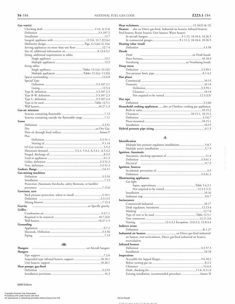
54-184 NATIONAL FUEL GAS CODE Z223.1-184
2009 Edition
Gas vent(s)Checking draft ...................................................................11.6, A.11.6Definition .............................................................................3.3.107.2Installation .....................................................................................12.7Integral, appliance with ...........................................12.3.6, 12.7.2(1)(e)Multistory design...................................................Figs. G.1(m)–G.1(n)Serving appliances on more than one floor ..................................12.7.4Size of, additional information on .........................................A.12.6.3.1Sizing, additional requirements to tables
Single appliance .....................................................................13.1Multiple appliances ................................................................13.2
Sizing tablesSingle appliance .........................................Tables 13.1(a)–13.1(f )Multiple appliances ....................................Tables 13.2(a)–13.2(i)
Spaces surrounding ......................................................................12.6.8Special Type
Definition ...................................................................3.3.107.2.1Listing.................................................................................12.5.4
Type B, definition ................................................................3.3.107.2.2Type B-W, definition ...........................................................3.3.107.2.3Type L, definition ................................................................3.3.107.2.4Type to be used ..................................................................Table 12.5.1Wall heaters.............................................................................10.27.1.3
Gas-air mixturesSystems containing flammable ........................................................7.12Systems containing outside the flammable range ............................7.11
GasesDefinition ..................................................................................3.3.51Dry .........................................................................see Dry GasFlow of, through fixed orifices ..................................................Annex FFlue
Definition ........................................................................3.3.51.1Venting of ...........................................................................9.1.14
LP-Gas systems ..............................................................................5.5.2Maximum demand ...................................5.4.1, 5.4.2, A.5.4.1, A.5.4.2Purged, discharge of .......................................................................8.3.3Used in appliances .........................................................................9.1.3Utility, definition ......................................................................3.3.51.2Vent, definition.........................................................................3.3.51.3
Gaskets, flange.....................................................................................5.6.11Gas-mixing machines
Definition ..................................................................................3.3.54Installation .....................................................................................7.12Protection (Automatic firechecks, safety blowouts, or backfirepreventers ..................................................................................7.12.6
Governor, zeroBack pressure protection, where to install ....................................5.10.1Definition ................................................................................3.3.112Mixing blowers ............................................................................7.12.4
Gravity ........................................................................see Specific gravityGrilles
Combustion air...........................................................................9.3.7.1Required to be removed ..........................................................10.7.2(3)Wall heaters.............................................................................10.27.1.5
GroundingAppliances ....................................................................................9.7.1Electrode, Definition ...................................................................3.3.56Piping .....................................................................................7.13
-H-Hangars .......................................................................see Aircraft hangarsHangers
Pipe support...................................................................................7.2.6Suspended-type infrared heaters, support ...................................10.18.1Unit heaters, support .................................................................10.26.1
Heat pumps, gas-firedDefinition ..................................................................................3.3.53Installation provisions .....................................................................10.2
Heat reclaimers ......................................................................12.16(3) & (5)Heaters also see Direct gas-fired, Industrial air heaters; Infrared heaters;Pool heaters; Room heaters; Unit heaters; Water heaters
In aircraft hangars ............................................9.1.12, 10.18.4, 10.26.5In commercial garages...................................9.1.11.2, 10.18.4, 10.26.5
Heating value (total)Definition ..................................................................................3.3.58
HoodsDraft ....................................................................see Draft hoodsDuct furnaces.............................................................................10.10.4Ventilating ...........................................................see Ventilating hoods
Hoop stressDefinition ...............................................................................3.3.99.1Test pressure limit, pipe ..............................................................8.1.4.2
Hot platesCommercial ..................................................................................10.13Domestic ...................................................................................10.14
Definition ........................................................................3.3.59.1Clearance .............................................................................10.14Not required to be vented ..............................................12.3.2(3)
Hot tapsDefinition ..................................................................................3.3.60
Household cooking appliances ......also see Outdoor cooking gas appliancesBuilt-in units..............................................................................10.15.2Clearances ..................................................................10.15.1, 10.15.2Definition .................................................................................3.3.6.7Floor-mounted...........................................................................10.15.1Installation ...................................................................................10.15
Hybrid pressure pipe sizing ..................................................................6.1.3
-I-Identification
Multiple line pressure regulators installations .................................5.8.7Multiple meter installations ...........................................................5.7.5
Ignition, AutomaticAutomatic, checking operation of ...................................................11.4Definition ...............................................................................3.3.61.1Electrical ....................................................................................9.7.2
Ignition, SourcesAccidental, prevention of ..................................................................4.3Definition ...............................................................................3.3.61.2
Illuminating appliancesGas light
Input, approximate...................................................Table 5.4.2.1Not required to be vented ...........................................12.3.2 (11)
Installation ...................................................................................10.16Sediment trap ................................................................................9.6.7
IncineratorsCommercial-industrial ..................................................................10.17Draft regulators, barometric .......................................................12.13.4Marking ..................................................................................12.7.6Type of vent to be used ......................................................Table 12.5.1Vent connectors ......................................................................12.11.2.6Venting ................................12.4.3.2 Exception, 12.6.3.2, 12.8.4.4
Indirect ovensDefinition .................................................................................K.1.27
Industrial air heaters........................................see Direct gas-fired industrialair heaters, non-recirculation, Direct gas-fired industrial air heaters,recirculation,
Infrared heatersDefinition ...............................................................................3.3.57.3Installation ...................................................................................10.18
InspectionsAccessible for, lapped flanges.....................................................5.6.10.2Before turning gas on.....................................................................8.2.2Chimneys ..................................................................................12.6.4Draft, checking for .............................................................11.6, A.11.6Existing installation, recommended procedure.........................Annex H
Copyright American Gas Association Provided by IHS under license with AGA
Not for ResaleNo reproduction or networking permitted without license from IHS
--`,,```,,,,````-`-`,,`,,`,`,,`---
//^:^^#^~^^""~:@":^*^~$~"#:*~::*^~:^^#~~#^~:^:@:~*:$"\\

Gas piping ...............................................................8.1, 9.6.8, A.8.1.1Ignition, automatic .........................................................................11.4Pressure regulating, limiting and relieving devices .......................5.9.1.2Protective devices ............................................................................11.5Safety shutoff devices ......................................................................11.3Vent connectors .......................................................................12.11.12
InstallationsAppliances, general ....................................................................Chap. 9Chimneys ......................................................................12.6.1–12.6.2Draft hoods and draft controls.....................................12.13.2–12.13.3Electrical .......................................................................................9.7Gas piping ...............................................................................Chap. 7Qualified agency, performed by ........................................................4.1Single-wall metal pipe for vents....................................................12.8.4Specific appliances ...................................................................Chap. 10
InstructionsAppliance installation...................................................................9.1.22Manufacturers, to be considered ....................................................1.1.2Operating, to be left with consumer ...............................................11.7
Insulating millboardDefinition ..................................................................................3.3.62Use of
Floor-mounted food service appliances.....................10.12.3.2 (2)Household cooking appliances .................................10.15.1.2 (1)Unlisted food service counter appliances ...........................10.13.4
InterruptionElectrical ....................................................................................9.7.2Of service ...............................................................4.2, 8.2.3, A.8.2.3
-J-Joining methods
Acceptable................................................................................5.6Joint compounds, thread ..................................see Thread joint compoundsJoints
Concealed piping, connections ......................................................7.3.2Corrosion, protection against ...........................................7.1.3, A.7.1.3Flared .................................................................................5.6.8.3Metallic ...................................................................5.6.8, A.5.6.8.1Plastic .....................................................................5.6.9, 7.5.2(2)Tubing .................................................................................5.6.8.2Vent connectors .........................................................................12.11.7
-K-Kettle
Definition ...............................................................................3.26.5.7Installation ...................................................................................10.12
-L-Labeled
Definition ....................................................................................3.2.3Laundry stoves, domestic
Definition ..................................................................................3.3.31Installation ...................................................................................10.14Not required to be vented .......................................................12.3.2(3)
Leak checkDefinition ..................................................................................3.3.64Suggested method....................................................................Annex D
Leak detectorsDefinition .................................................................................K.1.30Use of .................................................................................8.1.5.2
LeakageEmergency procedure for..........................................................Annex EPressure test....................................................................................8.1.5System, appliance and equipment test .................................8.2, A.8.2.3
Limit controls..............................also see Temperature limit controls/devicesProtective devices ............................................................................11.5
ListedDefinition ......................................................................3.2.4, A.3.2.4
Loads, connectedDefinition .................................................................................K.1.31
LouversIndustrial air heaters, direct fired
Non-recirculating.................................................10.8.5, 10.8.7.2Recirculating........................................................10.9.5, 10.9.7.2
Requirements for ...........................................................................9.3.7LP-Gas systems ..............................................................................5.5.2
-M-Main burners
Definition ...............................................................................3.3.17.4Prevent ignition ................................9.3.6.2, 9.3.7.3, 10.8.5, 10.8.7.2,10.9.5, 10.9.7.2, 12.4.3.5, 12.4.4.2
Mains, gas or distributionDefinition .................................................................................K.1.25
Maintenance.............................................................................................B.3Makeup air
Clothes dryer, Type 1 ................................................................10.4.3.1Combustion air for .........................................9.3.1.1 Exception No. 2Clothes dryer, Type 2 ................................................................10.4.3.2Direct gas fired heaters............see Direct gas-fired industrial air heaters,non-recirculation, Direct gas-fired industrial air heaters, recirculation,
Requirements for ...............................................................9.3.1.5Manifolds
Appliance shutoff valves at ..........................................................9.6.4.3Common Vent, definition.........................................................3.3.65.1Gas, definition ..........................................................................3.3.65.2Sizing of venting systems with .....................................................13.2.4
Manufactured gas .................................................................see utility gasesManufactured home (housing)
Appliances for ...............................................................................10.30Decorative appliance for ...........................................................10.6.2.2Definition ..................................................................................3.3.66
Manufacturer's instructions ..................................................................1.1.2Marking
Gas vents ..................................................................................12.7.6Single-wall metallic pipe ..............................................................12.8.7
Masonry chimneys............see Chimneys (masonry, metal, and factory-built)Maximum working pressure
Definition ...............................................................................3.3.81.4Overpressure relief device and ................................................5.9.1.1(2)Pressure-relieving and limiting ..............................5.9.2.1(4), 5.9.2.1(5)Test pressure................................................................................8.1.4.2
Mechanical exhaust systemsBooster-type water heater ........................................................12.3.2(5)Definition .............................................................................3.3.100.4Special conditions created by .........................................................A.9.3Vent termination......................................................................12.7.2(f )Venting in commercial applications..............................12.4.4, A.12.4.4
Metallic pipingAllowed ..........................................................................5.6.2, 5.6.3Appliance connections ...................................................................9.6.1Bends ....................................................................................7.5.1Connection to plastic piping.......................................................7.1.7.2Corrosion, protection against .................................5.6.6, 7.1.3, A.7.1.3Joints and fittings...........................................................................5.6.8Threads ....................................................................................5.6.7Turns .......................................................................................7.5
MetersDefinition ..................................................................................3.3.68Installation requirements...................................................................5.7Point of delivery, outlet of......................................................1.1.1.1(A)Testing for leakage using the ............................................................D.2
Millboard, insulating ..............................................see Insulating millboard
Z223.1-185 INDEX 54-185
2009 Edition
Copyright American Gas Association Provided by IHS under license with AGA
Not for ResaleNo reproduction or networking permitted without license from IHS
--`,,```,,,,````-`-`,,`,,`,`,,`---
//^:^^#^~^^""~:@":^*^~$~"#:*~::*^~:^^#~~#^~:^:@:~*:$"\\

54-186 NATIONAL FUEL GAS CODE Z223.1-186
Mixing blowersDefinition ..................................................................................3.3.69Special requirements.....................................................7.12.4, A.7.12.4
Multistory installationsVent, design principles......................................................Figure G.1(n)Vent, design procedure ....................................................Figure G.1(m)Vent, appliances on more than one floor......................................12.7.4Vent, offsets and capacity ...........................................................13.2.17Vent, size of lowest connector ....................................................13.2.15Vent, type B ...............................................................................13.2.16Vent height (H), measuring .......................................................13.2.14Vented wall furnaces in ...........................................................10.27.1.3
-N-NA
Definition ..................................................................................3.3.70Determining.......................................................13.1.1(2), 13.2.1(3)(b)
NAT Max, definition ...........................................................................3.3.71NAT + NAT, definition........................................................................3.3.72Noncombustible material
Air-conditioning installed on .......................................................10.2.4Definition ...............................................................................3.3.67.2Thimbles ...............................................................................12.8.4.6
Nondisplaceable valve memberDefinition .............................................................................3.3.106.1
Notification of interrupted service .......................................................4.2.1
-O-Openings .................................................................also see Relief openings
Chimneys ...............................................................................12.6.5.2Combustion air
Combination indoor and outdoor sizing...............................9.3.4Ducts ................................................................................ 9.3.8.4Exterior location above grade .............................................9.3.8.8Indoor ..................................................................................9.3.2Net free area, louvers, grilles and screens ............................9.3.7.1Outdoor sizing......................................................................9.3.3
Fire protection ................................................................7.4.2, 9.1.11.2Pipe, size of ....................................................................................5.9.8Tee and Wye Sizing....................................................................13.2.10
Operation of appliances, procedures .............................................Chap. 11Orifice cap (hood)
Definition .................................................................................K.1.32Orifice spud
Definition .................................................................................K.1.33Orifices
Definition ..................................................................................3.3.74Fixed, flow of gas through.........................................................Annex F
Outdoor cooking appliancesDefinition ...............................................................................3.3.6.10Installation ...................................................................................10.20
OutletsCapping .......................................................................8.1.3.4, 8.2.2Convenience ..............................................see Convenience outlets, gasPiping, branch connection ................................................................7.8Piping, location and installation........................................................7.7
OvensFood service, installation...............................................................10.12Domestic, installation ...................................................................10.15Indirect, definition ......................................................................K.1.27
Overpressure protectionDevices in vertical chases, piping ...................................................7.4.1Installation of devices, piping............................................................5.9Required, piping ...............................................................................5.9Setting ....................................................................................5.9.5Relief devices..................................................................................5.9.8Unauthorized operation .................................................................5.9.6
OxygenAs test medium ..............................................................................8.1.2Depletion safety shutoff system..................................................10.23.1Use under pressure .........................................................................9.1.5
-P-Parking structures
Appliance in..............................................................................9.1.11.1Basement or Underground, definition.......................................3.3.76.1Definition ..................................................................................3.3.76Enclosed, definition ..................................................................3.3.76.2
PartitionsPiping in ....................................................................................7.3.3Tubing in ....................................................................................7.3.4
PilotDefinition ..................................................................................3.3.77
Pipes and pipingAboveground outside ........................................................................7.2Bends .........................................................................7.5, A.7.5.3Branch ...........................................................................see BranchBuildings, in ..........................................................see Buildings, PipingBypass ....................................................................................5.8.6Clearances, underground piping ....................................................7.1.1Concealed .....................................................see Concealed gas pipingConnections .............................................see Connections; ConnectorsControl ...............................................................see Control pipingDefects ..........................................................................5.6.5, 8.1.5Drips .............................................................................7.2.3, 7.6Equivalent length .........................................................................C.3.2
Definition ........................................................................3.3.78.1Floors, in ....................................................................................7.3.5Hangers and anchors......................................................................7.2.6Identification, multiple meter installations.....................................5.7.5In vertical chases ...............................................................................7.4Independent.................................................................................10.2.1Inspection, testing, and purging ................................................Chap. 8Installation of..........................................................................7.2, 9.6.8Joining, acceptable methods..............................................................5.6Materials, acceptable .........................................................................5.6Metallic ...............................................................see Metallic pipingOutlets ...........................................................................see OutletsOverpressure ...............................................see Overpressure protectionPartitions, in ........................................................................7.3.3, 7.3.4Pipe, definition ............................................................................3.3.78Piping, definition .........................................................................3.3.79Plastic .....................................................................see Plastic pipeProhibited devices in .......................................................................7.10Prohibited locations..........................................................7.2.5, A.7.2.5Protection, underground piping.....................................................7.1.2Protective coating...........................................................................5.6.6Removal of ....................................................................................7.2.7Sediment traps ................................................7.6.3, 9.6.7, Figure 9.6.7Sizing and capacities of.......................................................5.4, Chap. 6
Additional appliances, adding .............................................9.1.16Branch Length Method ...........................................6.1.2, A.6.1.2Equations.................................................................................6.3Examples.........................................................................Annex CHybrid Pressure.....................................................................6.1.3Longest length method............................................6.1.1, A.6.1.1Tables for sizing LP systems .....................................................6.3Tables for sizing natural gas systems.........................................6.2
Sloped ..........................................................................7.2.3, 7.2.4Strain on, avoiding.......................................................................9.1.17Supports ......................................see Supports, Pipes and piping, gasTurns .......................................................................................7.5Underground ....................................................................................7.1Used materials.............................................................................5.6.1.2Valves, manual gas shutoff ................................................................7.9
2009 Edition
Copyright American Gas Association Provided by IHS under license with AGA
Not for ResaleNo reproduction or networking permitted without license from IHS
--`,,```,,,,````-`-`,,`,,`,`,,`---
//^:^^#^~^^""~:@":^*^~$~"#:*~::*^~:^^#~~#^~:^:@
:~*:$"\\

Workmanship ................................................................................5.6.5Piping systems, gas
Addition to existing .......................................................................5.1.2Definition .............................................................................3.3.100.5Design, materials, and components ...........................................Chap. 5Design pressure
Allowable pressure drop.................................5.4.1, 5.4.4, A.5.4.1Maximum .............................................................................5.5.1
Flexibility .....................................................................................5.14Gas-air mixtures
Containing flammable............................................7.12, A.7.12.4Outside the flammable range .................................................7.11
Interconnections between..................................................................5.3Leakage tests ...........................................................................8.1.5, 8.2Local conditions, consideration of................................................5.14.2Materials and joining methods ...............................................5.6, A.5.6Operating pressure limitations ..........................................................5.5
Maximum...........................................................5.5.1, A.5.5.1(1)Placing in operation, purging for ...................................................8.3.2Plan .......................................................................................5.1Point of delivery, location of .............................................................5.2Pressure drop, allowable .........................................5.4.1, 5.4.4, A.5.4.1Pressure testing and inspection ............................................8.1, A.8.1.1Purging ................................................8.3, Table 8.3.1, Table 8.3.2
Removal from service ............................................................8.3.1Sizing of .....................................................................5.4, Chapter 6
CSST ..................................see Corrugated Stainless Steel TubingPlastic ...................................................................see Plastic pipesSchedule 40 Metallic ......................see Schedule 40 metallic pipesTubing..........................................................................see Tubing
Thermal expansion..........................................................................5.14Plastic pipe
Appliance venting, used inVent material approval ........................................................12.5.2Within chimney flue..............................................9.3.8.7, 12.6.8
Gas delivery, used forAnodeless risers ..................................................................5.6.4.3Bends ....................................................................................7.5.2Connection of.......................................................7.1.7.1, 7.1.7.2Installation ............................................................................7.1.1Joining ..................................................................................5.6.9Materials ...............................................................................5.6.4Regulator vent, used for ....................................5.6.4.2, A.5.6.4.2Sizing
Equations .......................................................................6.4Tables, LP...........................................Tables 6.3(k)–6.3(m)Tables, natural gas ................................Tables 6.2(r)–6.2(v)
Tracer wire to locate....................................................................7.1.7.3Plenum
Definition ..................................................................................3.3.80Piping allowed in........................................................................A.7.2.5
Plenum, furnaceClearance ...........10.2.3 (5), 10.2.3 (6), 10.3.2.6, 10.3.2.8–10.3.2.10Definition ..................................................................................3.3.48Installation ......................................................................10.2.5, 10.3.7Venting systems through ..............................................................12.4.5
Point of deliveryLocation of .......................................................................................5.2Scope ...........................................................................1.1.1.1 (A)
Pool heatersDefinition ...............................................................................3.3.57.4Installation ...................................................................................10.21Power, continuous..........................................................................9.7.4
PressureAtmospheric, definition ............................................................3.3.81.1Back
Definition ........................................................................3.3.81.2Protection ..............................................................................5.10
Definition ..................................................................................3.3.81Design ..............................................................see Design pressureLimitations ..................................................................5.5.1, A.5.5.1(1)Low, protection...............................................................................5.11Maximum working, definition ..................................................3.3.81.4Operating, limitations on..................................................................5.5Overpressure ...............................................see Overpressure protectionRegulators ......................................................................see Regulators
Pressure controlDefinition .................................................................................K.1.34
Pressure dropAllowable ............................................................5.4.1, 5.4.4, A.5.4.1Definition ..................................................................................3.3.82
Pressure limiting devicesDefinition ...............................................................................3.3.29.2Pool heater ................................................................................10.21.3Water heater...............................................................................10.28.3
Pressure regulators ...............see Overpressure protection devices; RegulatorsPressure relief devices ......................also see Overpressure protection devices
Protective devices ............................................................................11.5Steam safety and ..........................................................10.3.6, A.10.3.6Water heaters .............................................................................10.28.5
Pressure testsDefinition ..................................................................................3.3.83Requirements ......................................................................8.1, A.8.1.1
Primary airAdjustment ........................................................11.2, A.11.2, Annex HDefinition .................................................................................3.3.2.4
ProtectionAppliances
From fumes or gases ................................................9.1.6, A.9.1.6Outdoor..............................................................................9.1.23
Back pressure ..................................................................................5.10Control piping, external.................................................................5.9.4Corrosion .........................................see Corrosion, protection againstFloor furnaces ..........................................................................10.11.10Gas pressure regulators...................................................................5.8.4Overpressure, devices ........................................................................5.9Physical, gas appliances ................................................................9.1.13Piping, underground......................................................................7.1.2Low pressure ...................................................................................5.11Meters, gas ....................................................................................5.7.4
Protective devicesAppliances .....................................................................................11.5
Purge/purgingDefinition ..................................................................................3.3.84Piping .....................................8.3, Table 8.3.1, Table 8.3.2, A.8.3
-Q-Qualified agency
Definition ..................................................................................3.3.85General .......................................................................................4.1Notification of Interrupted service, duty........................................4.2.1
Quick-disconnect devicesDefinition ...............................................................................3.3.29.3Not required to be capped................................7.7.2.1 Exception No. 2Outdoor connections.................................................................9.6.2(2)Outlets .................................................................................7.7.1.6Requirements for ...........................................................................9.6.5
-R-Radiant appliances ..see Decorative appliances, to install in vented fireplacesRanges ................................................see Household cooking appliancesReferenced publications.................................................Chap. 14, Annex MRefrigeration systems
Boilers used with..........................................................................10.3.9Coils ..................................................................................10.3.8
Z223.1-187 INDEX 54-187
2009 Edition
Copyright American Gas Association Provided by IHS under license with AGA
Not for ResaleNo reproduction or networking permitted without license from IHS
--`,,```,,,,````-`-`,,`,,`,`,,`---
//^:^^#^~^^""~:@":^*^~$~"#:*~::*^~:^^#~~#^~:^:@:~*:$"\\

54-188 NATIONAL FUEL GAS CODE Z223.1-188
2009 Edition
Duct furnaces used with.............................................................10.10.6Refrigerators, (using gas fuel)
Definition ..................................................................................3.3.87Installation provisions ...................................................................10.22Not required to be vented .......................................................12.3.2(6)
Regulations, gas supplier ......................................................................1.1.2Regulator vents
Definition .............................................................................3.3.107.3Gas appliance pressure regulators .................................................9.1.19Pressure reduction, with .................................................................7.4.1
RegulatorsDefinition ..................................................................................3.3.88Draft ..............................................................see Draft regulatorsGas appliance pressure
Definition ........................................................................3.3.88.1Illuminating appliances .....................................................10.16.5Venting of ..............................................................5.8.5.2, 9.1.19Where required ...................................................................9.1.18
Gas pressureDefinition ........................................................................3.3.88.5Identification of ....................................................................5.8.7Installation ....................................................................5.8, A.5.8Line, definition ................................................................3.3.88.3Line, venting of.....................................................................5.8.5Listing...................................................................................5.8.2Location................................................................................5.8.3Protection of .........................................................................5.8.4
Monitoring, definition ..............................................................3.3.88.4Series, definition .......................................................................3.3.88.6Service, definition .....................................................................3.3.88.7Vent, definition.......................................................................3.3.107.3Where required ..............................................................................5.8.1
Relief openingsDefinition ..................................................................................3.3.89Direct gas-fired industrial air heaters
Non-recirculating................................................................10.8.7Recirculating .......................................................................10.9.7
Draft, checking ...............................................................................11.6Draft regulators............................................................12.13.6, 12.13.7
RepairsDraft, checking the .........................................................................11.6Piping
Following leakage test ...........................................................8.2.3Following pressure test .......................................................8.1.1.3
Pressure regulating, limiting, relieving devices.............................5.9.1.2Work interruption..........................................................................4.2.2
Required volumeCombination indoor & outdoor combustion air ......................9.3.4 (3)Indoor combustion air ...................................................................9.3.2Retroactivity of code .........................................................................1.3
RisersAnodeless see Anodeless risersCorrosion, protection against ......................................................7.3.5.2
Roofs, appliance on..................................................................................9.4Room heaters
Clearance ................................................................................10.23.4Institutions, installations in........................................................10.23.3Part of cooking appliance, clearances ..................................10.15.1.1(2)Prohibited installations .............................................10.23.1, A.10.23.1Unvented
Definition ........................................................................3.3.57.6Not required to be vented ..............................................12.3.2(8)
Vented, definition........................................................................K.1.40Wall-type ................................................................................10.23.5
Room large in comparison with size of applianceAir conditioners, in
Listed, clearances ...........................................................10.2.3 (1)Listed and unlisted, reduced clearances ..................................10.2.3 (4)
Air conditioners, NOT in Listing and clearances ...................10.2.3 (2)Central furnaces and boilers, in
Listed, clearances..............................................................10.3.2.1Listed and unlisted, reduced clearances ............................10.3.2.4Unlisted, clearances ..........................................................10.3.2.3
Central furnaces and boilers, NOT in Listing & clearances .........10.3.2.2Clearance to combustible material..................................Table 10.2.3(a)Definition ..................................................................................3.3.90
-S-Safety blowouts (backfire preventers)....................see Gas-mixing machines
Definition ..................................................................................3.3.91Safety inspection, existing appliance installation.........................Annex. HSafety shutoff devices
Chimneys connected to gas and liquidfuel appliances...........................................................................12.6.5.2Clothes dryers, multiple family or public use ...............................10.4.6Definition ...............................................................................3.3.29.4Installation .....................................................................................11.3Unlisted LP-gas appliances used indoors ........................................9.1.4
Safety shutoff valvesGas-mixing machines .............................................7.12.5.4, A.7.12.5.4
Schedule 40 Metallic Pipe .......................................also see Metallic piping,Pipes and Piping, Piping systems, gasSizing
Methods...................................................................................6.1Equations.................................................................................6.3Tables, LP......................................................Tables 6.3(a)–6.3(d)Tables, Natural Gas........................................Tables 6.2(a)–6.2(e)
Scope of code............................................................................................1.1Seepage pan .......................................................................................10.11.9Separate users, interconnections supplying .........................................5.3.1Service head adapters
Definition ..................................................................................3.3.92Installation ...........................................................................5.6.4.3 (2)
Service meter assemblyApplicability of code .............................................................1.1.1.1 (A)Definition ..................................................................................3.3.93
Service regulators ......................................................see Regulators, PressureShall
Definition ....................................................................................3.2.5Shutoff devices
Automatic gas, definition ..........................................................3.3.29.1Clothes dryers, multiple-family or public use...............................10.4.6Definition ...............................................................................3.3.29.4Safety .....................................................................................11.3Safety, for unlisted LP appliances ...................................................9.1.4Water heaters .............................................................................10.28.5
Shutoff valvesAccessible .......................................................................see AccessibleAppliance, definition...............................................................3.3.105.1Appliances
Gas hose connectors, use of ...............................9.6.2(1), 9.6.2(2)Installed in a branch piping system ....................................9.6.4.1Installed in a manifold piping system.................................9.6.4.3Required ...............................................................................9.6.4Serving fireplace appliances .............................9.6.4.1 (2), 9.6.4.2Use of during pipe pressure testing ....................................8.1.3.5
Emergency .................................................................................7.9.2.3For multiple house lines..............................................................7.9.2.2Installation requirements.................................................................5.12Installed in fireplaces...................................................................7.7.2.2Manual gas .............................................................................7.9, 9.6.4Service, definition ...................................................................3.3.105.2
Sources of ignition ........................................................see Ignition, SourcesSpaces
Combustion air, combining ........................................................9.3.2.3Gas meters, ventilated .................................................................5.7.2.1
Copyright American Gas Association Provided by IHS under license with AGA
Not for ResaleNo reproduction or networking permitted without license from IHS
--`,,```,,,,````-`-`,,`,,`,`,,`---
//^:^^#^~^^""~:@":^*^~$~"#:*~::*^~:^^#~~#^~:^:@
:~*:$"\\

Z223.1-189 54-189
2009 Edition
Surrounding chimney lining or vent ...............................9.3.8.7, 12.6.8Well-ventilated .............................................................................12.3.3
Specific gravityDefinition ..................................................................................3.3.96Stand-by fuels, interconnections for ...............................................5.3.2
Steam cookersDefinition ..............................................................................3.3.6.5.5
Steam generatorsDefinition ..............................................................................3.3.6.5.6
StressAppliance connection..................................................................9.1.8.4Definition ..................................................................................3.3.99Hoop
Definition ........................................................................3.3.99.1Test pressure limit, pipe .....................................................8.1.4.2
Pipe design ..................................................................................5.14.1Structural stresses, pipe installation .............................................7.2.2.1Underground pipe damage protection............................................7.1.2
Structural members, building ...............................................................9.1.8Supports
AppliancesChecking building structure adequacy ...............................9.1.8.4Prevent damage to buildings ..............................................9.1.8.3Prevent strain on piping......................................................9.1.17Roof structure adequacy ....................................................9.4.1.2
Chimneys ..................................................................................12.6.6Furnaces
Duct ................................................................................10.10.2Floor ................................................................................10.11.6
Gas vents ..................................................................................12.7.5Heaters
Infrared .............................................................................10.18.1Unit ................................................................................10.26.1
Illuminating appliances ..............................................................10.16.3Meters, gas ....................................................................................5.7.3Pipes and piping, gas
Aboveground.........................................................................7.2.1Materials ...............................................................................7.2.6Spacing of....................................................7.2.6.2, Table 7.2.6.2Special local conditions .......................................................2.13.2
Single-wall metallic pipe, vent......................................................12.8.6Vent connectors .......................................................................12.11.10
Suspended-type unit heaters ..........................................................10.26.2.1Switches, in electrical supply line.......................................................10.2.7
-T-Temperature, ambient ...................................... also see Weather conditions
Definition ...................................................................................K.1.1Temperature limit controls/devices
Boilers, steam and hot water ........................................................10.3.4Floor furnaces ............................................................................10.11.2Pool heaters................................................................................10.21.3Water heaters .............................................................................10.28.4
Temperature relief devices, water heaters .........................................10.28.5Tensile strength
Definition ................................................................................3.3.101Plastic pipe joint.......................................................................5.6.9 (1)
Termination, venting systems .........................................see Venting systemsTesting, piping system
Defects, pressure test for ................................................................8.1.5Leakage
Pressure test for detection......................................................8.1.5System, appliance and equipment test ........................8.2, A.8.2.3
Pressure .........................................................................8.1, A.8.1.1Thermostats
Definition ................................................................................3.3.102Floor furnaces.......................................................................10.11.1 (3)Room temperature ............................................................................9.8
ThimbleChimney connection................................................................12.11.11Passing through roof
All vents ........................................................................12.7.2 (6)Single-wall metal pipe .......................................12.8.4.2, 12.8.4.7
Vent connectors, used with .......................................12.8.4.7, 12.11.11Threads
Metallic fittings greater than 4 inch.......................................5.6.8.4 (1)Metallic pipe ..................................................................................5.6.7Pipe joints allowed ......................................................................5.6.8.1
Thread joint compoundsDefinition ................................................................................3.3.103Gas and chemical resistance ........................................................5.6.7.4
Toilets, gas-firedClearances for connectors ................................................Table 12.8.4.5Installation provisions ...................................................................10.25Vents for ........................................................................Table 12.5.1
Traps, sediment ...........................................................................7.6.3, 9.6.7Trenches
Backfilling .................................................................................7.1.2.3Grading .................................................................................7.1.2.2
Tubing .......................................also see Corrugated stainless steel tubingAppliance connections .................................9.6.1(2), 9.6.1(5), 9.6.1(7)Concealed ....................................................................................7.3.2Connecting gas appliances.........................................................9.6.1(2)Metallic
Joints .................................................................................5.6.8.2Used with corrosive gases ......................................................5.6.3
Partitions, in ..................................................................................7.3.4Plastic
Joints ....................................................................................5.6.9Use of ...................................................................................5.6.4
Sizing and capacitiesEquations.................................................................................6.4Tables, plastic
LP ..................................................................Tables 6.3(m)Natural Gas .......................................Tables 6.2(u) – 6.2(v)
Tables, semi-rigidLP ......................................................Tables 6.3(e) – 6.3(g)Natural Gas ........................................Tables 6.2(f ) – 6.2(l)
Support spacing ....................................................7.2.6.2, Table 7.2.6.2Workmanship and defects ....................................................5.6.5, 8.1.5
Type B gas vents .....................................................................see Gas vent(s)Type B-W gas vents ................................................................see Gas vent(s)Type L vents............................................................................see Gas vent(s)
-U-Underground piping
Installation provisions .......................................................................7.1Unit broilers
Clearances ................................................................................10.12.1Definition ...............................................................................3.3.15.1
Unit heatersDefinition ...............................................................................3.3.57.5Installation ...................................................................................10.26Suspended-type unit heaters....................................................10.26.2.1
Utility gasesDefinition ...............................................................................3.3.51.2Multipliers for other specific gravity.........................................Table F.3Orifice size ..............................................................................Table F.1
-V-Vacuum relief devices
Valve, definition...................................................................3.3.105.4.3Water heaters .............................................................................10.28.5
Valve membersAppliances shutoff valves and connections .....................................9.6.4
Copyright American Gas Association Provided by IHS under license with AGA
Not for ResaleNo reproduction or networking permitted without license from IHS
--`,,```,,,,````-`-`,,`,,`,`,,`---
//^:^^#^~^^""~:@":^*^~$~"#:*~::*^~:^^#~~#^~:^:@
:~*:$"\\

54-190 NATIONAL FUEL GAS CODE Z223.1-190
Definition ................................................................................3.3.106Nondisplaceable, definition.....................................................3.3.106.1Quick-disconnect devices ...............................................................9.6.5
Valves ...................................................................also see Shutoff valvesAccessibility of ............................................................................7.9.2.1Automatic, definition..............................................................3.3.105.1Bypass
Line pressure regulators, around............................................5.8.6Pool heaters.......................................................................10.21.4
Controlling multiple systems .........................................................7.9.2Definition ................................................................................3.3.105Diaphragm-type, bleed lines for ...................................................9.1.20Mixing blowers.............................................................7.12.4, A.7.12.4Pressure relief, checking operation of appliance...............................11.5Pressure relief, pool heater.......................................................10.21.3.2Pressure relief and steam safety, boilers .........................10.3.6, A.10.3.6Used .................................................................................5.6.1.2
Vapors, flammable, gas appliances in area of ..........................9.1.9, 9.1.10Vehicular fuel systems, compressed natural gas ..................................10.29Vent(s)
Atmospheric, used with valves, gas reliefs, bleeds .............10.8.6, 10.9.6Definition ................................................................................3.3.107Gas .....................................................................see Gas vent(s)Obstructions .........................................................12.16, 13.1.1, 13.2.1Regulator, definition ...............................................................3.3.107.3Sizing of .....................................................................see Gas vent(s)Toilets, gas-fired .........................................................................10.25.3
Vent connectorsBends avoiding unnecessary .......................................................12.11.6Category I appliances, for .............................................................12.11Category II, III, IV appliances ......................................................12.12Chimneys ...........................see Chimneys Chimneys (masonry, metal,
and factory-built)Clearance .......................................................12.11.5, Table 12.8.4.5Combined prior to entering vent (manifold)................................13.2.4Corrugated Size..........................................................................13.1.12Dampers ........................................................................12.14–12.15Definition ................................................................................3.3.108Inspection ..............................................................................12.11.12Joints ................................................................................12.11.7Length ....................................................................12.11.9, 13.2.2Location, where entering chimney ...........................................12.11.11Materials .........................................................Table 12.5.1, 12.11.2,Mechanical draft systems...........................................................12.4.3.4Obstructions .........................................................12.16, 13.1.1, 13.2.1Rise ................................................................................13.2.12Routing ..................................................................................13.2.3Size of
General............................................................12.11.3, A.12.11.3Two or more appliances ................................12.11.3.3, 12.11.3.4
Alternate method.....................................................12.11.4Using multiple appliance tables.......................... 13.2.24–13.2.26Using single appliance tables ...............................13.1.12–13.1.14
Slope ................................................................................12.11.8Support ..............................................................................12.11.10Through ceilings, floors, or walls .............................................12.11.14Toilets, gas-fired .........................................................................10.25.3
Vent damper devices, automatic............see Damper devices, automatic ventVent gases
Definition ...............................................................................3.3.51.3Vented appliances
Category I, definition.............................................................3.3.6.11.1Category II, definition ...........................................................3.3.6.11.2Category III, definition..........................................................3.3.6.11.3Category IV, definition ..........................................................3.3.6.11.4Venting systems, Category I appliances ...................................Chap. 13
Ventilating hoodsBroilers, domestic, used with .....................................................10.19.3
Used to vent appliances, commercial ............................12.3.3, A.12.3.3Ventilation
Air for .......................................................................................9.3Appliances ..............................................................................9.1.2 (1)
For appliances not required to be vented.............................12.3.2Well-ventilated industrial spaces..........................................12.3.4
Chase ......................................................................7.4.3, A.7.4.3Food service appliances.............................................10.12.8, A.10.12.8Infrared heaters ..........................................................................10.18.3Open-top broiler units .................................................10.19.3, 10.19.4
VentingAppliances, of .........................................................Chap. 12, Chap. 13Appliances not requiring venting .................................................12.3.2Definition ................................................................................3.3.110Flue gases ..................................................................................9.1.14Overpressure protection devices .....................................................5.9.7Pressure regulators....................................................5.8.5, 7.4.1, 9.1.19
Venting systems.....................................................................also see VentingAppliances ...................................................................9.1.2(3), 9.1.14Category I, sizing of ................................................................Chap. 13Connection to .........................................................see Vent connectorsDefinition .............................................................................3.3.100.6Design and construction .................................................................12.4Pool heaters................................................................................10.21.5Refrigerators...............................................................................10.22.2Sizing of, examples (appliances equipped with draft hoods orlisted for use with Type B vent)................................................Annex GTermination
Chimneys............................................................................12.6.2Gas vents.............................................................................12.7.2Mechanical draft systems..................................................12.4.3.6Single-wall metal pipe .........................................................12.8.3Through the wall.......................................................12.9, A.12.9
Type of system to use.................................................12.5, Table 12.5.1Use of ventilating hoods, commercial...........................................12.3.3
-W-Wall furnaces
Definition ...............................................................................3.3.47.7Direct vent, definition...............................................................3.3.47.2Installation ...................................................................................10.27Type B-W gas vent use ............................................................12.7.1(2)Type of venting system to be used ......................................Table 12.5.1Vented .................................................................see Wall furnaces
Wall head adapterConnection of plastic pipe ...............................7.1.7.1 Exception No. 2Definition ................................................................................3.3.111
Wall-type room heatersInstallation ................................................................................10.23.5Unvented closed front, definition................................................K.1.44
Water heatersAnti-siphon devices ..................................................10.28.7, A.10.28.7Automatic instantaneous type ....................................................10.28.6Bedrooms and bathrooms, in .....................................................10.28.1Booster, not required to be vented...........................................12.3.2(5)Definition ...............................................................................3.3.57.7Input, approximate............................................................Table 5.4.2.1Installation ...................................................................................10.28Temperature, pressure, and vacuum relief devices.........10.28.3–10.28.5Venting in, exterior masonry chimneys.................................13.1.11 (5)
Weather conditionsCold climate, uninsulated single-wall metal pipe .........................12.8.2Pipe protection .................................................................7.1.4, A.7.1.4Special local conditions, pipe protection ......................................5.14.2Wind, floor furnace protection ................................................10.11.10
Work interruptions, piping ..................................................................4.2.2
2009 Edition
Copyright American Gas Association Provided by IHS under license with AGA
Not for ResaleNo reproduction or networking permitted without license from IHS
--`,,```,,,,````-`-`,,`,,`,`,,`---
//^:^^#^~^^""~:@":^*^~$~"#:*~::*^~:^^#~~#^~:^:@
:~*:$"\\

Sequence of Events Leading to Publicationof an NFPA Committee Document
Call goes out for proposals to amend existing document or forrecommendations on new document.
•
Committee meets to act on proposals, to develop its own proposals,and to prepare its report.
•
Committee votes on proposals by letter ballot. If two-thirds approve,report goes forward. Lacking two-thirds approval, report returns
to committee.
•
Report — Report on Proposals (ROP) — is published for public reviewand comment.
•
Committee meets to act on each public comment received.
•
Committee votes on comments by letter ballot. If two-thirds approve,supplementary report goes forward. Lacking two-thirds approval,
supplementary report returns to committee.
•
Supplementary report — Report on Comments (ROC) — is publishedfor public review.
•
NFPA membership meets (Annual or Fall Meeting) and acts on commit-tee report (ROP or ROC).
•
Committee votes on any amendments to report approved at NFPAAnnual or Fall Meeting.
•
Appeals to Standard Council on Association action must be filed within20 days of the NFPA Annual or Fall Meeting.
•
Standards Council decides, based on all evidence, whether or not to issuestandard or to take other action, including upholding any appeals.
Sequence of Events Leading to Publicationof an ANSI ASC Z223 Committee Document
Call goes out for proposals to amend existing document. Proposalsreceived prior to the call are included in revision process.
•
Committee meets to act on each proposal, to develop its own proposals,and to prepare the public review document.
•
Committee votes on proposals at the meeting or by letter ballot. If two-thirds approve, public review document goes forward. Lacking two-thirds
approval, document returns to committee. Persons submitting proposals arenotified to the action taken.
•
First Public Review document is published.
•
Committee meets to act on each public comment received.
•
Committee votes on comments at the meeting or by letter ballot. Iftwothirds approve, changes goes forward for a final letter ballot. Lackingtwo-thirds approval, document returns to committee. Persons submitting
comments are notified to the action taken and advised of their appeal rights.
•
Committee votes and actions that result in substantive changes arepublished as additional Public Review document(s) and the above step
is repeated.
•
Final letter ballot – Committee votes on final revised document by letterballot. If two-thirds approve, revised document is submitted to ANSI for
approval. Lacking two-thirds approval, document is returned to committee.
•
Appeals to Committee must be filed within 30 days of notification.
•
ANSI Board of Standard Review decides, based on consensus evidence,whether or not to approve document.
Z223.1-191 54-191
2009 Edition
M/M Manufacturer: A representative of a maker or marketer of is aproduct, assembly, or system, or portion thereof, that is affected bythe standard.
U* User: A representative of an entity that is subject to the provisionsof the standard or that voluntarily uses the standard.
ES† Energy Supplier: A representative of an entity that supplies energyto installations covered by the standard.
I-M/I-M Installer-Maintainer: A representative of an entity that is in thebusiness of installing or maintaining a product, assembly, or systemaffected by the standard.
L* Labor: A representative or employee concerned with safety in theworkplace.
R-T/R-T Applied Research-Testing Laboratory: A representative of anindependent testing laboratory or independent applied researchorganization that promulgates and/or enforces standards.
EA/EA Enforcing Authority: A representative of an agency or an organiza-tion that promulgates and/or enforces standards.
I/I Insurance/Insurance: A representative of an insurance company,broker, agent, bureau or inspection agency.
C* Consumer: A person who is, or represents, the ultimate purchaserof a product, system, or service affected by the standard, but who isnot included in the User classification.
SE/SE Special Expert: A person not representing any of the previousclassifications, but who has special expertise in the scope of thestandard or portion thereof.
Committee Membership ClassificationsThe following classifications apply to Committee members and represent their principal interest in the activity of a committee. Categories for the NFPA 54 andZ223 committees are denoted as follows (NFPA 54 / Z223):
*NFPA 54 Committee only. †Z223 Committee only.
NOTE 1: “Standard” connotes code, standard, recommended practice, or guide.
NOTE 2: A representative includes an employee.
NOTE 3: While these classifications will be used by the NFPA Standard Council or ASC Z223 to achieve a balance for the committee, the Standards Council orASC Z223 Committee may determine that new classifications of members or unique interests need representation in order to foster the best possible com-mittee deliberations on any project. In this connection, the Standards Council and the ASC Z223 Committee may make such appointments as it deemsappropriate in the public interest, subject to NFPA or ANSI procedures.
NOTE 4: Representatives of subsidiaries of any group are generally considered to have the same classification as the parent organization
Copyright American Gas Association Provided by IHS under license with AGA
Not for ResaleNo reproduction or networking permitted without license from IHS
--`,,```,,,,````-`-`,,`,,`,`,,`---
//^:^^#^~^^""~:@":^*^~$~"#:*~::*^~:^^#~~#^~:^:@
:~*:$"\\

PROPOSAL FORM: ANSI Z223.1/NFPA 54NATIONAL FUEL GAS CODE
Date
Name
Tel. No. E-mail
Company
Street Address City State Zip
Please Indicate Organization Represented (if any) ______________________________________________Please indicate in which format you wish to receive your Public Review or ROP/ROC document:�� electronic �� paper �� download (Note: In choosing the download option you intend to view the Public Review
or ROP/ROC from our Websites, no copy will be sent to you)
1. Section/Paragraph ______________________________________________2. Proposal recommends (check one) �� new text �� revised text �� deleted text3. Proposal (include proposed new or revised wording, or identification of wording to be deleted): (Note: Proposed textshould be in legislative format: i.e., use underscore to denote wording to be inserted (inserted wording) and strikethroughto denote wording to be deleted (deleted wording).
4. Statement of Problem and Substantiation for Proposal: (Note: State the problem that will be resolved by your recom-mendation; give the specific reason for your comment including copies of tests, research papers, fire experience, etc. Ifmore than 200 words, it may be abstracted for publication.)
5. �� This Proposal is original material. (Note: Original material is considered to be the submitter’s own idea based on oras a result of his/her own experience, thought, or research ad, to the best of his/her knowledge, is not copied fromanother source.)
�� This Proposal is not original material, its source (if known) is as follows:
I hereby grant the AGA. and NFPA all and full rights in copyright, in this proposal, and I understand that I acquire norights in any publication of AGA. and NFPA in which this proposal or another similar or analogous form is used.
Signature (Required): ______________________________________________�� Check this box if filing electronically to indicate your acceptance of the above permission statement.
PLEASE USE SEPARATE FORM FOR EACH PROPOSAL
Send to: Secretary, National Fuel Gas CodeAmerican Gas Association, 400 N. Capitol St., NW, Washington, DC 20001
Fax: 202.824.9122, Email: [email protected] American Gas Association Provided by IHS under license with AGA
Not for ResaleNo reproduction or networking permitted without license from IHS
--`,,```,,,,````-`-`,,`,,`,`,,`---
//^:^^#^~^^""~:@":^*^~$~"#:*~::*^~:^^#~~#^~:^:@:~*:$"\\
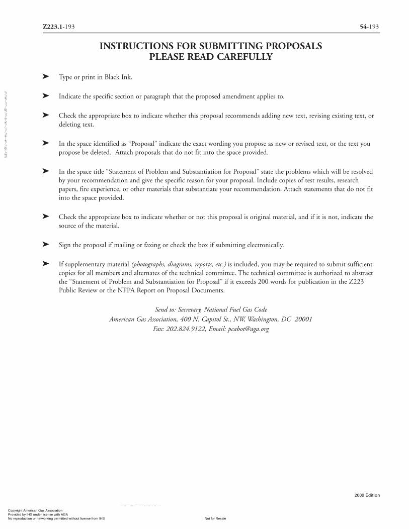
INSTRUCTIONS FOR SUBMITTING PROPOSALS PLEASE READ CAREFULLY
� Type or print in Black Ink.
� Indicate the specific section or paragraph that the proposed amendment applies to.
� Check the appropriate box to indicate whether this proposal recommends adding new text, revising existing text, ordeleting text.
� In the space identified as “Proposal” indicate the exact wording you propose as new or revised text, or the text youpropose be deleted. Attach proposals that do not fit into the space provided.
� In the space title “Statement of Problem and Substantiation for Proposal” state the problems which will be resolvedby your recommendation and give the specific reason for your proposal. Include copies of test results, researchpapers, fire experience, or other materials that substantiate your recommendation. Attach statements that do not fitinto the space provided.
� Check the appropriate box to indicate whether or not this proposal is original material, and if it is not, indicate thesource of the material.
� Sign the proposal if mailing or faxing or check the box if submitting electronically.
� If supplementary material (photographs, diagrams, reports, etc.) is included, you may be required to submit sufficientcopies for all members and alternates of the technical committee. The technical committee is authorized to abstractthe “Statement of Problem and Substantiation for Proposal” if it exceeds 200 words for publication in the Z223Public Review or the NFPA Report on Proposal Documents.
Send to: Secretary, National Fuel Gas CodeAmerican Gas Association, 400 N. Capitol St., NW, Washington, DC 20001
Fax: 202.824.9122, Email: [email protected]
Z223.1-193 54-193
2009 Edition
Copyright American Gas Association Provided by IHS under license with AGA
Not for ResaleNo reproduction or networking permitted without license from IHS
--`,,```,,,,````-`-`,,`,,`,`,,`---
//^:^^#^~^^""~:@":^*^~$~"#:*~::*^~:^^#~~#^~:^:@
:~*:$"\\

IMPORTANT NOTICES AND DISCLAIMERS CONCERNINGAGA and NFPA DOCUMENTS
(Continued from inside front cover)
ADDITIONAL NOTICES AND DISCLAIMERS Updating of AGA and NFPA Documents
Users of NFPA codes, standards, recommended practices, and guides and AGA Z223.1 should be aware that these documents
may be su perseded at any time by the issuance of new editions or may be amended from time to time through the issuance of Tenta -
tive Interim Amendments and addendum. An official AGA or NFPA document at any point in time consists of the current edition
of the document together with any Tentative Interim Amendments and any Errata then in effect. In order to determine whether a
given doc ument is the current edition and whether it has been amended through the issuance of Tentative Interim Amendments or
corrected through the issuance of Errata, consult appropriate NFPA publications such as the National Fire Codes Subscrip tion
Service, visit the NFPA website at www.nfpa.org, or contact the AGA or NFPA at the address listed below.
Interpretations of AGA and NFPA Documents
A statement, written or oral, that is not processed in accordance with the interpretation procedures of the Z 223 Committee or
with Section 6 of the Regulations Governing Committee Projects shall not be considered the official position of the Z 223
Committee or the NFPA or any of its Committees and shall not be consid ered to be, nor be relied upon as, a Formal Interpretation.
Patents
The AGA and the NFPA do not take any position with respect to the validity of any patent rights asserted in connection with
any items which are mentioned in or are the subject of AGA and NFPA codes, standards, recommended practices, and guides, and
the AGA and the NFPA disclaim liability for the infringement of any patent resulting from the use of or reliance on these docu-
ments. Users of these documents are expressly advised that determination of the validity of any such patent rights, and the risk of
infringement of such rights, is entirely their own responsibility. AGA and NFPA adhere to applicable policies of the American
National Standards Institute with respect to patents. For further information, contact the AGA or NFPA at the address listed below.
Laws & Regulations
Users of these documents should consult applicable federal, state, and local laws and regulations. The AGA and the NFPA do
not, by the publication of their codes, standards, recommended practices, and guides, intend to urge action that is not in compli -
ance with applicable laws, and these documents may not be construed as doing so.
Copyrights
This document is copyrighted by the AGA and the NFPA. It is made available for a wide variety of both public and private uses.
These include both use, by reference, in laws and regulations, and use in private self-regulation, standardization, and the promotion
of safe practices and methods. By making this document available for use and adoption by public au thorities and private users, the
AGA and the NFPA do not waive any rights in copyright to this document.
Use of AGA and NFPA documents for regulatory purposes should be accomplished through adoption by reference. The term
“adoption by reference” means the citing of title, edition and publishing information only. Any deletions, additions, and changes
desired by the adopting authority should be noted separately in the adopting instrument. In order to assist NFPA in following the
uses made of its documents, adopting authorities are requested to notify the NFPA (Attention: Secretary, Standards Council) in writ-
ing of such use. For technical assistance and questions concerning adoption of AGA and NFPA documents, contact the AGA or the
NFPA at the address below.
For Further Information
All questions or other communications relating to AGA and NFPA codes, standards, recommended practices, and guides and all
requests for information on AGA and NFPA procedures governing their codes and standards development process, including in -
formation on the procedures for requesting Formal Interpretations, for proposing Tentative Interim Amendments, and for propos-
ing revisions to AGA or NFPA documents during regular revision cycles, should be sent to AGA headquarters, addressed to the atten-
tion of the Secretary, Accredited Standards Committee Z 223, 400 N. Capitol Street, N.W., Washington, DC 20001 and to NFPA
headquarters, ad dressed to the attention of the Secretary, Standards Council, NFPA, 1 Batterymarch Park, P.O. Box 9101, Quincy,
MA 02269-9101.
Copyright American Gas Association Provided by IHS under license with AGA
Not for ResaleNo reproduction or networking permitted without license from IHS
--`,,```,,,,````-`-`,,`,,`,`,,`---
//^:^^#^~^^""~:@":^*^~$~"#:*~::*^~:^^#~~#^~:^:@
:~*:$"\\

NationalFuel Gas Code2009
EDITION
NFPA® 54ANSI Z223.1
An American National Standard
American Gas Association
National Fuel G
as Code - 2009
American Gas Association
NFPA® 54
ANSI Z223.1
The American Gas Association, founded in 1918, represents 202 local energy companies that deliver natural gas throughout the United States. There are nearly 70 million residential, commercial and industrial natural
gas customers in the U.S., of which 92 percent — more than 64 million customers — receive their gas from AGA members. Today, natural gas meets almost one-fourth of the United States’ energy needs.
One of AGA’s primary missions is to encourage and assist its members in sharing information designed to achieve operational excellence by improving their efficiency, reliability and safety. AGA fulfills part of that mission by serving as the Secretariat for three ANSI Accredited Standards Committees (ASC) and publishing key industry technical standards including:
• ANSIASCZ223.1;NationalFuelGasCode• ANSIASCGPTCZ380;GuideforGasTransmissionandDistributionPipingSystems• ANSIASCB109;theB109seriesofstandardsongasdisplacementmetersandservice
regulators
ForpublicationinformationcontacttheAmericanGasAssociation’spublicationfulfillmentfacilitytollfreeat(800)699-9277orvisitusonthewebatwww.aga.org.Formoreinformation on association activities or membership contact: American Gas Association, 400 N.CapitolStreet,N.W.,Washington,DC20001(202/824-7000orFAX202/824-7115).
NFPA® membership keeps you up-to-date on the latest information you need to make the best decisions on the job. Members have exclusive access to the most current fire and life safety research, vital code update information, online reports and statistical data, technical assistance, and professional contacts. In addition, members receive subscriptions to the NFPA Journal®, NFPA Update,
and NFPA News, free membership to one of 16 special interest groups, and discounts on NFPAproducts.
National Fuel Gas Code Handbook, 2009 Edition
Applyfuelgasprovisionscorrectlyfromthestartwiththe2009NFPA54:National Fuel Gas Code Handbook. The only complete guide to today’s Code, the Handbook is an essential on-the-job resource for troubleshootingandtraining.WrittenbyNFPAauthorities,ithelpsyoumaximize fire safety and fire protection, steer clear of roadblocks, and keep fuel gas piping, appliance, and venting projects in compliance and on schedule.
ToorderorformoredetailsonotherNFPAproductsorseminars,calltoll-free 1-800-344-3555.ForordersoutsidetheUnitedStates,call617-770-3000. Visit our online catalog at nfpacatalog.org.
KJ-MIS-1Z 5409
NFPA54CodeCover09.indd1 8/21/083:51:59PM
Copyright American Gas Association Provided by IHS under license with AGA
Not for ResaleNo reproduction or networking permitted without license from IHS
--`,,```,,,,````-`-`,,`,,`,`,,`---
//^:^^#^~^^""~:@":^*^~$~"#:*~::*^~:^^#~~#^~:^:@:~*:$"\\