national aeronautics and space administration · 2013-04-10 · counsel for patent matters ......
TRANSCRIPT

REPLY TO ATTNOF G P
NATIONAL AERONAUTICS AND SPACE ADMINISTRATION WASHINGTON. D.C. 20546
July 6, 1971
ME240RANDUM
,,TO : KSI/Scientific & Technical Information Division “;r
A t t n : M i s s Winnie M. Morgan
FROM: GP/Of f ice of A s s i s t a n t General Counsel f o r Patent Matters
SUBJECT : Announcement of NASA-Owned U.S. Pa ten ts in STAR
I n accordance with t h e procedures contained i n t h e Code G P t o code US1 memorandum on t h i s subject , dated June 8, 1970, t he attached NASA-owned U.S. patent is being forwarded f o r abs t rac t ing and announcement i n NASA STAR.
The following information i s provided:
U . S . Patent No. : 3,396,920
Corporate Source : Hughes Aircraf t Company
Supplementary Corporate Source
NASA Patent C a s e No.:
Enclosure : Copy of Patent
/ - .I
I
CI) I O
9
(NASA CR OR TMX OR AD NUMBER)
https://ntrs.nasa.gov/search.jsp?R=19710019574 2018-08-26T10:33:07+00:00Z
Aug. 13, 1968 H. A. ROSEN ETAL 3,396,920 OF A SPINNING BODY TRA~JHSGG A
Filed Dec. 30, 1959 d.@!!e- .“- k h e e t s - s h e e t 1
APPARATUS FOR CHANGING THE ORIENTATILAND VELOCITY
“.., *d’#”y
\-*
HAROLD A ROSEN, DONALD D WILLIAMS,
INVENTORS
B V W 6. AGENT

Aug. 13, 1968 H. A. ROSEN ETAL 3,396,920 APPARATUS FOR CHANGING THE ORIENTATION AND VELOCITY
OF A SPINNING BODY TRAVERSING A PATH Filed Dec. 30, 1959 6 Sheets-Sheet 2
8- 62 ,,
8 7759.7
HAROLD A . ROSEN, DONALD 0. WILLIAMS,
INVENTORS
BYW 4 u AGENT
Aug. 13, 1968 H. A. ROSEN ETAL 3,396,920 AFPARATUS FOR CHANGING THE ORIENTATION AND VELOCITY
OF A SPINNING BODY TRAVERSING A PATH Filed Dec. 30, 1959 6 Sheets-Sheet 3
H A R O L D A . R O S E N , D O N A L D D. WILLIAMS,
INVENTORS
AGENT

Aug. 13, 1968 H. A, ROSEN ETAL 3,396,920 APPARATUS FOR CHANGING THE ORIENTATION AND VELOCITY
OF A SPINNING BODY TRAVERSING A PATH Filed Dec. 30, 1959 6 Sheets-Sheet 4
HAROLD A . ROSEN, DONALD D. WILLIAMS,
INVENTORS
smd8. - AGENT

Aug. -113, 1968 H. A. ROSEN ETAL 3,396,920 APPARATUS FOR CHANGING THE ORIENTATION AND VELOCITY
OF A SPINNING BODY TRAVERSING A PATH Filed Dec. 30, 1959 6 Sheets-Sheet 5
OF FIFTH STAGE
EXPLOSIVE CWRRGE 60 OF
SIXTH STAGE ROCKET 36
80 t81 OF
CORRECTION
FIRST ORIENTATION SIGNAL
C H A R G I N G DIODES
FIRST ORIENTATION SEN S I N G
SOLAR CELLS
S O L A R R A Y S
r - - G ~ - j 9 6 ORIENTATION
ORIENTATION SENSING
73
HAROLD A . ROSEN, DONALD D. WILLIAMS,
INVENTORS
WYs-4 8. w A G E N T

Aug.. 13, 1968 H. A. ROSEN ETAL 3,396,920 APPARATUS FOR CHANGING THE ORIENTATION AND VELOCITY
OF A SPINNING BODY TRAVERSING A PATH Filed Dec. 30, 1959 6 Sheets-Sheet 6
I02\ F-7. /2. 80
100
100
100
102,
100
HAROLD A . ROSEN, DONALD D. WILLIAMS,
INVENTORS
BY 171*ca f?. AGENT

3,396,920 United States Patent Office Aug. 13, 1968
1 2
3,396,920 APPARATUS FOR CHANGING THE QRIENTATION
VERSING A PATH Harold A. Rosen, Sanh Monica, and Donald D. Williams,
Inglewood, Calif., granted to National Aeronautics and Space Administration under the provisions of 42 U.S.C. 2457(d)
AND VELOCITY OF A SPINNING BODY TRA-
Filed Dee. 30, 1959, Ser. No. 862,921 2 Claims. (el. 244-1)
The present invention relates to space vehicles such as satellites and, more particularly, to a method and ap- paratus for spinning a satellite about a particular axis having a predetermined orientation with respect to the earth after the satellite has reached a selected orbit.
Man-made satellites placed into orbit around the earth are often provided with equipment requiring the satellites to be accurately placed into specific orbits and to be oriented in a predetermined manner. For example, a satel- lite for use as a radio communication relay may have to be accurately placed into a west-to-east circular orbit in the plane of the earth’s equator and having a period of 24 hours. Such an orbit is desirable because the satellite hovers above a single point on the earth, inasmuch as both the satellite and the earth have the same angular velocity. A satellite which hovers above a single point on the earth must be accurately placed iiito an orbit having a 22,750 nautical mile radius from the center of the earth and the satellite must travel around the orbit with a linear velocity of 10,090 feet per second.
An active communication satellite, that is, one which is equipped to receive and retransmit radio waves, is pro- vided with an antenna and may be provided with solar cells as a source of power. To increase the antenna gain, the sateliite should ?be spinning about the antenna axis and this axis should be parallel to the earth’s axis. In this way, the antenna radiation pattern may be omnidirectional about the antenna axis but have a narrow beam width about a plane extending through the center of the satellite perpendicular to the antenna axis. This system provides increased antenna gain, 8 decibels, for example, in the direction of the earth and permits the use of a radio trans- mitter having a relatively low power output, thus reduc- ing size and weight requirements. Further, solar cells need be placed only on those surfaces of the satellite that in- tercept maximum light from the sun.
It may be found that the satellite drifts relative to a precise stationary orbit and requires correction over a period of time. The possible drift due to errors in the ve- locity of the satellite has been determined to be 39.4 de- grees per year per foot per second of velocity error.
To keep the cost of the satellite and the launching rocket as low as possible, the satellite and its apparatus for orientation and stabilization should be simple in opera- tion, light in weight, and small in size.
Accordingly, it is an object of the present invention to provide apparatus for orienting a spin-stabilized vehicle such as a satellite in a predetermined orbit in space.
Another object of the invention is the provision of ap- paratus for correcting the orbit of a spin-stabilized ve- hicle such as a satellite.
Another object of the invention is the provision of ap- paratus for stopping the spin of a space vehicle such as a satellite about a first axis and spinning the vehicle about a new axis perpendicular to the first axis.
Yet another object of the present invention is to pro- vide increased antenna gain in a spinning vehicle such as a space satellite.
A further object of the invention is the provision of o p timum solar cell illumination in an orbiting space satel- lite.
5
10
15
20
25
30
35
40
45
50
55
60
65
70
Still another object of the present invention is to pro- vide apparatus for orienting a spin-stabilized satellite which is simple in form, reliable in operation, small in size, light in weight, inexpensive, and low in power con- sumption.
In accordance with these and other objects of the inven- tion, an orbiting satellite having a radio antenna and solar cells is oriented with respect to the earth and the sun to optimize the satellite antenna gain and the solar cell illu- mination. The satellite enters its orbit spinning about a first axis extending through an attached rocket case. The desired spin axis is perpendicular to the first spin axis. Means is provided for stopping the spin of the satellite about the first axis by rotating the satellite with respect to the rocket case. Means is provided for sensing the orienta- tion of the satellite relative to the earth, the sun, or both.
Knowing the orientation of the satellite, the instant that the satellite has ceased to spin about the first spin axis can be determined and also the orientation of the desired new spin axis with respect to the earth’s axis can be sensed. At the instant that the satellite has ceased to spin about the first axis and the desired new spin axis is simultaneous- ly parallel to the earth’s axis, the rocket case is separated from the satellite. Means is provided to spin the satellite about the new axis after separation of the rocket case from the satellite.
Deviations from the correct orbital period, eccentricity and phase are determined from observations made from the earth. Means is provided to correct orbital deviations by applying a reaction force to the satellite with a prede- termined momentum and in the proper direction.
The following specification and the accompanying draw- ings describe and illustrate an exemplification of the pres- ent invention. Consideration of the specification and the drawings will provide a complete understanding of the invention, including the novel features and objects there- of. Like reference characters are used to designate like parts throughout the figures of the drawings.
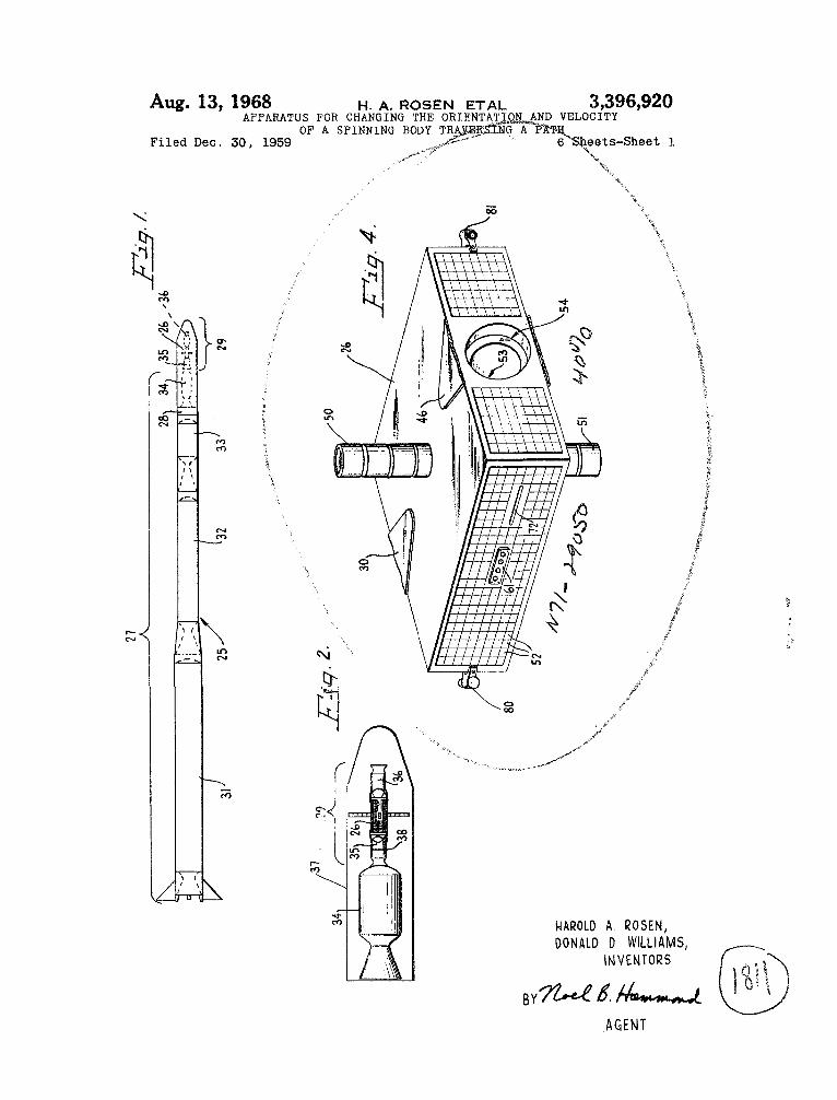
FIG. 1 is a view in elevation of an exemplary embodi- ment of a satellite launching vehicle in accordance with the invention showing the relationship of the propulsion rockets to the satellite;
FIG. 2 is an enlarged elevational view of a portion of the launching vehicle of FIG. 1 showing the relationship of fourth, fifth, and sixth stage rockets to the satellite and enclosing heat shield;
FIG. 3 is an isometric view of the sixth stage rocket showing the arrangement of a vernier propulsion system;
FIG. 4 is a perspective view of the satellite showing the arrangement of various mechanical features thereof;
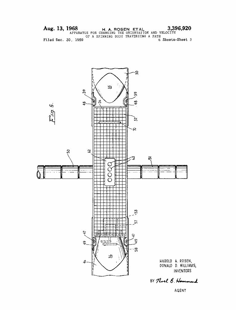
FIG. 5 is an elevational view partly in section of a portion of the fifth and sixth stage rockets and the satel- lite showing yokes which fasten the rockets to the satellite and an arrangement for severing the yokes;
FIG. 6 is a sectional view of a portion of the satellite and the sixth stage rocket case showing a de-spin and separation arrangement;
FIG. 7 is an elevational view of an orbital correction
FIG. 8 is a cross-sectional view of the orbital correction
FIG. 9 is a detail view of the solar sensing arrangement; FIG. 10 is a diagram of the satellite control circuitry; FIG. 11 is a diagram of a satellite trajectory from the
earth to a desired orbit; FIG. 12 is a diagram indicating the initial spin of
the satellite and the sixth stage rocket about the rocket axis;
FIG. 13 is a diagram indicating the alignment of the antenna axis of the satellite parallel to the earth’s axis while the sixth stage rocket continues to rotate;
gun;
gun of FIG. 7 taken on the line 8-8 of FIG. 7;

3,396,920 3 4
FIG. 14 is a diagram illustrating the separation of the 1 and 2, comprises a fifh stage rocket 35, a sixth stage sixth stage rocket from the satellite; rocket 36 and the satellite 26. The gross payload 29 and
FIG. 15 is a diagram indicating the final spin of the the fourth stage rocket 34 are covered by a nose shell satellite about the antenna axis parallel to the earth’s axis; or cylindrical heat shield 37 until the launching vehicle and 5 25 leaves the earth’s atmosphere. The heat shield 37 is
FIG. 16 is a diagram showing the application of a then automatically separated from the gross payload 29 reaction force to the satellite in a predetermined direc- and the fourth stage rocket 34. The construction and tion. method of separation of a typical nose shell is illus-
Although the present invention does not embrace a trated on page 6 of the Chance Vought publication. vehicle for conveying a satellite to an orbit, a brief de- The fifth stage solid-propellant rocket 35, which is scription of a representative rocket vehicle useful for this secured in tandem to the fourth stage rocket 34, provides purpose is included. Reference is hereby made to the the additional thrust required for the satellite 26 to reach book “Rocket Encyclopedia Illustrated,” edited by J. W. the perigee of the transfer ellipse. The fifth stage rocket Herrick 2nd E. Burgess, Aero Publishers, Inc., Los 35 is provided with means, such as an electrically fused Angeles, Calif., 1959, and to the bibliography therein for 15 annular explosive charge 38 (FIG. 2) which encircles details of rocket vehicles and definitions of terms. the case of the fifth stage rocket 35, for reducing the
There is shown in FIG. 1 an exemplary embodiment thrust to zero. When detonated, the explosive charge 38 of a rocket vehicle, indicated generally by the numeral ruptures the combustion chamber of the fifth stage rocket 25, for accurately launching a space vehicle such as 35. satellite 2.6 into a predetermined orbit around the earth. 20 The sixth stage rocket 36 provides the additional thrust In the present example, the orbit in which the satellite to establish the satellite 26 in the circular orbit from 26 is to be placed is a so-called stationary orbit, which is the apogee or highest point of the transfer ellipse. The a circular west-to-east equatorial orbit having a period sixth stage rocket 36 is secured to the satellite 26 on of 24 hours. This orbit has a radius of 22,750 nautical the side opposite the side to which the fifth stage rocket miles from the center of the earth and the satellite 26 25 35 is secured, and is oriented in the opposite direction. travels at a velocity of 10,090 feet per second (f.p.s.) in That is, the fifth stage rocket 35 is oriented so that the the direction of the earth‘s rotation and appears to stand rocket exhaust nozzle extends out from the satellite 26 in still or hover over one point on the earth‘s surface. The the opposite direction from that in which the exhaust satellite 26 may then be uscd, for example, to relay radio nozzle of the fifth stage rocket 35 extends out from the communications over long distances. 30 satellite 26. As will be fully apparent hereinafter, this is
The primary or booster portion of the rocket vehicle necessary so that the thrust of the sixth stage rocket 36 25 is a multistage rocket power plant designated by the will be applied in the correct direction. numeral 27 in FIG. 1 and comprising first, second, third, The sixth stage rocket 36 establishes the satellite 26 in and fourth stage rockets 31, 32, 33, and 34, respectively, only an approximate 24-hour orbit and any velocity rror
engines may be used, the use of solid propellant rocket above a point on the earth. Accordingly, a vernier pro- engines for the multistage rocket power plant 27 results pulsion system 40 is provided to establish a more ac- in a simpler, less expensive, and more reliable rocket curate 24-hour period anti, as shown in FIG. 3, the vernier vehicle 25. The first, second, and third stage rockets 31,. ProPulsion system 40 includes a toroidal bottle 41 con- 32, and 33 are. provided with guidance means such as jet 40 taining compressed nitrogen gas, which encircles 6he vanes (not shown) which are disposed in the jet stream neck of the sixth stage rocket 36. An electrically op- from the rocket exhaust nozzle to deflect the jet and erated valve 42 is connected by tubing 43 between the thus obtain a turning force to control the direction and outlet of the bottle 41 and a pair of exhaust nozzles 44 attitude of the vehicle 25. Such an arrangement is shown and 45 on diametrically opposite sides of the main exhaust on page 248 of the above-referenced Rocket Encyclopedia. 45 nozzle of the sixth stage rocket 36. Thus, gas is supplied The fourth stage rocket 34 is provided with means such simultaneously to both nozzles 44 and 45 when the valve as spin nozzles or spin rockets (not shown) to rotate the 42 is actuated, to supply additional thrust in controlled fourth stage rocket 34 about its longitudinal axis for sta- amounts. bilization. Such arrangements are shown and described As may best be seen in FIG. 4, the satellite 26 has on pages 456 and 457 of the Rocket Encyclopedia. The 50 a rectangular box-like configuration, the dimensions of ignition of the rocket engines, jettisoning of burned out whioh may be 9 x 24 x 24 inches, for example, and rockets, guidance, and spin stabilization of the multistage the satellite 26 may weigh on the order of 20 pounds, for rocket power plant 27 is automatically controlled by a example. A Pair of antenna elements 50 and 51 extend guidance unit 28, which may be one of several types of putwardly from the opposite faces of the satellite 26 hav- programming and control systems that are well known 55 ing the largest area along an axis extending through the in the art of rocketry. center of the satellite 26 perpendicular to the longitudinal
If desired, the multistage rocket power plant 27 may axis of the rocket vehicle 25. The antenna elements 50 be, for example, the “Scout” rocket developed for the and 51 provide a radiation pattern that is substantially National Aeronautics and Space Agency by Vought omnidirectional about the antenna axis, but has a narrow Astronautics Division of Chance Vought Aircraft, Inc., 60 beam width about a plane extending through the center Dallas, Tex. Reference is made to the publication entitled of the satellite 26 perpendicular to the antenna axis. The “Space Research Vehicle Systems” developed from NASA four sides of the satellite 26 parallel to the antenna axis Scout, publication number E9R-12402, dated August are provided with solar cells, indicated by the numeral 1959 and published by Chance Vought Aircraft, Inc. for 52, for converting sunlight into electrical energy. The rec- details of the Scout rocket. In particular, on page 23 of 65 tangular configuration of the satellite 26 has been selected the Chance Vought publication, there is a description to provide an optimum area of solar cells 52 exposed to of a guidance system developed by the Minneapolis- the sun during spin about the axis of the antenna elements Honeywell Regulator Co. which may be used as the 59 and 51 and still provide suitable orientation of the guidance unit 28 in the present rocket vehicle 25. satellite 26 in the heat shield 37 of the gross payload 29.
AS shown in FIG. 5, the fifth and sixth stage rockets Payload 29, which may weigh on the order of 100 pounds, 35 and 36 are secured to the satellite 26 by means of tubu- for example, to a point near the perigee of the transfer lar yokes 30 and 46 extending from the cases of the rock- ellipse, that is, near the lowest point of the elliptical tra- ets 35 and 36, respectively, which are joined to the sur- jectory from the outer atmosphere of the earth to the faces of the satellite 26 from which the antenna elements desired orbit. The gross payload 29, best seen in FIGS. 75 50 and 51 extend. Explosive charges 39 and 47 are dis-
arranged in tandem. Although liquid propellant rocket 36 causes the satellite 26 to drift from a stationary pos e tion
The multistage rocket power plant 27 propels a gross 70

3,396,920 5 6
posed on the inside surfaces of the yokes 30 and 46, field of view designated as alpha (a), the solar cell 71 is respectively, adjacent the edges of the satellite 26 for energized to develop a potential a t its output terminals. severing the yokes 30 and 46 after the rockets 35 and Referring to FIG. 4, a secund slit 72 is provided on the 36 are burned out. The explosive charges 39 and 47 are opposite face of the satellite 26 and which extends in a shaped so that the explosive force will be primarily di- 5 plane transverse to the plane of the first slit 70. Similarly, rected through the yokes 30 and 46 and away from the a second orientation sensing solar cell 73 (FIG. 9) dis- satellite 26. The solar cells 52 are shielded from the ef- posed within the satellite 26 develops a potential when fects of the explosive charges 39 and 47 by shields 48 the sun is in the fan-shaped field of view of the second and 49, made of a frangible material, such as balsa wood, slit 72. disposed around the explosive charges 39 and 47. Miniature rockets 80 and 81 (FIG. 4) are secured to
The sixth stage rocket 36 is rotatably secured to the lo the satellite 26 at diagonally opposite corners thereof. satellite 26 as well as being fastened to it by the yoke The miniature rockets 80 and 81 may be of the type 46. As shown in FIGS. 4, 5, and 6, the satellite 26 is shown on page 389 of the referenced Rocket Encyclo- provided with a depression or well 53 in the face there- pedia and are oriented to direct their thrust in a plane of adjacent the sixth stage rocket 36. The well 53 is 15 perpendicular to the antenna axis which passes through stepped in diameter to provide a recess 54 at the outer the center of gravity of the satellite 26 and in a direc- extremity thereof. The sixth stage rocket 36 is provided tion tangential to a radius line extending from the center with a cylindrical rim or extension 55, which extends into of the satellite 26 to the rockets 80 and 81. The rockets the recess 54. An annular ball bearing 56 disposed in 80 and 81 are provided with electrical igniters. the recess 54 encircles the outer wall of the extension 55 20 As will be seen in FIG. 10, the satellite 26 is provided so that the satellite 26 will rotate freely with respect to with a radio transmitter and receiver 90 that is electrically the sixth stage rocket 36 after the yoke 46 has been connected to the antenna elements 50 and 51 as indicated. severed. a source of potential, such as a storage battery 91, applies
An electric motor 57 is fastened to the sixth s t a g rocket electrical power to the radio transmitter and receiver 36 and extends through the inside of the extension 55 25 90. The solar cells 52 disposed on the outer surface of and into the well 53, being held therein by friction. A the satellite 26 are connected through rectifiers or charg- planetary gear train 58 is disposed within the sixth stage ing diodes 92 to the battery 91 to maintain it in a charged rocket 36 adjacent to the driving shaft of the motor 57 condition. Approximately 2200 solar cells 52 may be pro- and is mechanically coupled thereto. Electrical connec- vided and are grouped into four banks, one bank on each tion to the motor 57 is made by a quick-disconnect con- 30 face of the satellite 26 parallel to the antenna axis. The tact arrangement 59 which extends through the bottom cells 52 in each bank are connected in a series-parallel ar- of the well 53 into the satellite 26. The contact arrange- rangement, and although there may be different numbers ment 59 may be of any well-known type such as bi- of cells 52 in each bank, the number of cells in series in furcated springs, which engage contact pins. The arrange- each series-parallel arrangement is the same to provide ment for supplying power to the motor 57 will be de- 35 the Proper voltage for the battery 91. The charging diodes scribed hereinafter. When the motor 57 is energized, the 92 are nonconductive during periods that the voltage de- satellite 26 rotates with respect to the sixth stage rocket veloped by any bank of cells 52 drops below that of the 36 in a direction opposite to the spin imparted thereto battery 91. by the fourth stage rocket 34. At the bottom of the A radio control circuit 93 is also connected to the radio well 53 is an explosive charge 60 which, when ignited, 40 transmitter and receiver 90 and to the battery 91. The forces the motor 57 and ball bearing 56 out of the well radio control circuit 93 is responsive to control signals 53, thereby separating the sixth stage rocket 36 from received by the radio transmitter and receiver 90 for the satellite 26. applying a potential from the battery 91 to the various
Means is provided for making minor corrections in the electrically controlled devices associated with the satel- orbital period, eccentricity, and phase of the satellite 45 lite 26 and the fifth and sixth stage rockets 35 and 36. 26. Referring to FIGS. 4 and 5, a pair of guns 61 and 62 The particular radio remote control system utilized may is disposed within the satellite 26 with their muzzles be one Of several systems well known in the art, f m ex- opening on two opposite faces of the satellite 26 in a ample, one utilizing subcarrier signals transmitted on a plane perpendicular to the antenna axis and passing carrier wave. The radio control circuit 93 may, 6or ex- through the center of gravity of the satellite 26. The guns 50 ample, include a number of filters for separating the vari- 61 and 62 are multiple-shot devices and, as may be Seen ous subcarrier signals and actuating relays in response in FIG. 7, may have four barrels 63, Each of the barrels thereto, as is well known in the art. 63 is of the same caliber but each is provided with a bullet The explosive charge 38 for rupturing the combustion or projectile 64 (FIG. 8) within it which has a different chamber of the fifth stage rocket 35 and likewise the ex- mass and a different charge of powder 65. Thus, each of 55 plosive charge 39 for severing the Yoke 30 connecting the barrels 63, when fired, produces a different impulse. the fifth stage rocket 35 to the satellite 26, are individual-
The guns 61 and 62 are fired by the electrical ignition ly connected to Outputs Of the radio control circuit 93. The of a primer 66 in the rear of each of the barrels 63 through igniter for the Sixth stage rocket 36 is also connected to an electrical contact assembly 67 extending into the the radio control circuit 93. The control valve 42 of the satellite 26 through the rear of the guns 61 and 62. Each 60 vernier Propulsion system 4o and the explosive charge of the barrels 63 may be fired independently of the others 47 for severing the yoke 46 On the sixth stage rocket 36 and the of the projectiles 64 and the charge of the are similarly separately connected to the radio oontrol powder 65 are selected so that impulse increments in a circuit 93. The electric motor 57 and the explosive binary ratio of 1:2:4:8 may be obtained. Thus, if the charge 60 for separating the sixth stage rocket 36 from
the satellite 26 are also connected to separate outputs smallest impulse is '/s pound-second (1b.-sec.), for ex- 65 of the radio control circuit 93. The miniature rockets ample, any impulse in increments of YB 1b.-sec. from % to and 81 on the satellite 26 and the orbital correction 1% 1b.-sec. may be obtained by firing selected combina- connected tions of barrels 63.
The satellite 26 is also provided with means for sensing The first and second orientation sensing solar cells 71 its orientation with respect to the sun. In FIG. 5, there 70 and 73 =e respectively connected to first and second is shown a slit 70 provided in the outer wall of the satel- orientation signal oscillators 95 and 96. The orientation lite 26 and extending parallel to the antenna axis. Refer- sensing solar cells 71 and 73 supply electrical power for ring to FIG. 9, a single orientation sentsing solar cell 71 the oscillators 95 and 96 so that orientation signals are is disposed inside the satellite 26 adjacent the slit 70 developed when the solar cells 71 and 73 are illuminated so that when the sun is within the fan-shaped angular 75 by the sun. The output signals from the oscillators 95 and
guns 61 and 62 are in like fashion to the radio control circuit 93.

3,396,920 a 8
96 are applied to the radio transmitter and receiver 90 hereinbefore the sixth stage rocket 36 is secured to the for transmission to a satellite control point (not shown). satellite 26 with an orientation such that it applies thrust Thus, if the satellite 26 is spinning about the rocket axis in the direction opposite to that of the thrust of the fifth and the sun is in the plane described or swept out by the stage rocket 35. antenna axis, a periodic signal will be developed by the 5 At the highest point or apogee 109 of the transfer el- second oscillator 96; but if the satellite 26 is spinning lipse 105, the satellite 26 has attained the altitude of the about the antenna axis and the sun is in the plane de- desired circular 24-hour orbit 112 but is traveling at only scribed or swept out by the rocket axis, a periodic signal 5200 f.p.s., which is less than that required for establish- will be developed by the first oscillator 95. ment of the satellite 26 in the orbit 112. A radio control
In the construction of the satellite 26, the mass of the signal is transmitted to the satellite 26 to cause ignition of units associated with the satellite 26 is accurately deter- the sixth stage rocket 36 to provide the additional ve- mined and the equipment is distributed within the satellite locity of 4890 f.p.s. to establish the satellite 26 into the 26 so that the center of gravity is made to coincide with circular orbit 112. At the apogee 109 on the other side the center of the satellite 26; and the axis of maximum of the earth 100 from the firing point 103, the direction of moment of inertia is made to coincide with the antenna 15 thrust of the sixth stage rocket 36 is such as to cause the axis. satellite 26 to enter the circular orbit 112 due to the fact
#Referring now to FIG. 11, the earth is represented by that the sixth stage rocket 36 has maintained its attitude the circle designated 100 and is rotating in the counter- in space while traversing the transfer ellipse 105 and due clockwise direction indicated by the arrow 101 around an to the fact that the orientation of the sixth stage rocket 36 axis represented as going into the drawing through the 20 is opposite to that of the fifth stage rocket 35. north pole 102. The rocket vehicle 25 is fired from a point Inasmuch as the satellite 26 may have velocity and alti- 103 on the equator of the earth 100, which may be, for tude errors, it only approximately enters the 24-hour sta- example, Jarvis Island in the Pacific Ocean. Prior to fir- tionary orbit 112, and corrections are made by radio con- ing, the battery 91 is completely charged and the radio trol of the electrically controlled vernier propulsion sys- transmitter and receiver 90 and the radio control circuit 25 tem 40. The satellite 26 is tracked from the earth 100 by 93 are placed in operation. After firing, the first four means of radio signals transmitted to the satellite 26 and rockets 31-34 of the propulsion system 27 are automati- relayed back to the earth 100 to determine the drift of the cally fired in sequence and guided by the guidance unit 28 satellite 26 relative to the earth 100. The velocity of the and after burnout, each empty rocket case is jettisoned, as satellite 26 is increased by opening the valve 42 of the is well known in the art. 30 vernier propulsion system 40 for controlled time ifitervals
After the rocket vehicle 25 has attained considerable by means of radio control signals. Opening of the valve altitude, the rocket vehicle 25 is automatically turned in 42 results in jets of compressed nitrogen issuing from the the direction of rotation of the earth 100 by the guidance nozzles 44 and 45 to provide a reaction force that in- unit 28, that is, in an easterly direction. Prior to separa- creases the velocity of the satellite 26. tion of the third stage rocket 33 and ignition of the fourth 35 After the satellite 26 has been brought more accurately stage rocket 34, the fourth stage rocket 34 has a spin into the 24-hour orbit 112, a control signal is transmitted about its longitudinal axis imparted to it at a rate of about which results in the detonation of the explosive charge 47. 3 revolutions per second (r.p.s.) to provide spin stabiliza- This severs the yoke 46 so that the sixth stage rocket 36 tion, after which the heat shield 37 and the guidance unit is held to the satellite 26 only by the friction between 28 are automatically jettisoned. The multistage rocket 40 the outside of the electric motor 57 and the bearing 56 power plant 27 propels the gross payload 29 to a point and the sides of the well 53. above the earth 100 near the lowest point or perigee 104 The Satellite 26 is now spinning about the longitudinal of an elliptical trajectory or transfer ellipse 105. axis of the sixth stage rocket 36 at a rate of about three
At this point, the gross payload 29 has attained an alti- r.P.8. due to the spin imparted to the fourth stage rocket tude of approximately 150 nautical miles and has a hori- 45 34 for stabilization as it travels in the orbit 112. The axis zontal velocity, or velocity in a direction perpendicular to Of spin is in the equatorial plane of the earth SO that a line between the center of the earth 100 and the gross two times in each revolution of the satellite 26 about the payload 29 of about 31,500 feet per second (f.p.s.). After rocket axis, the antenna axis, which will be the final burnout, the fourth stage rocket 34 is automatically jet- spin axis, iS parallel to the earth's axis 102 (FIG. 12). A tisoned and the fifth stage rocket 35 is automatically fired 50 control Signal is transmitted to the satellite 26 which to provide the additional thrust necessary to bring the ve- causes the motor 57 to be energized, thereby rotating the locity up to 33,500 f.p.s., causing the satellite 26 to reach satellite 26 about the rocket axis with respect to the sixth the perigee 104 and to traverse the transfer ellipse 105. stage rocket 36. The direction of rotation of the motor Because the velocity of the satellite 26 at the perigee 104 57 is such that the satellite 26 rotates with respect to is quite critical in order to achieve the correct apogee, the 55 the rocket 36 in the opposite direction to the initial spin velocity will be measured from the earth 100 in a well of the rocket 36. The speed of rotation of the motor 57 known manner, such as by means of a radio interferom- is such that the satellite 26 rotates with respect to the eter, for example. When the correct velocity has been at- rocket 36 at a rate equal to the original spin rate of three tained, a radio control signal is transmitted from the earth r.p.s. multiplied by the ratio of the moment of inertia 100 to the satellite 26 to fire the explosive charge 38 and 80 of the satellite 26 and the rocket 36 to the moment of rupture the combustion chamber of the fifth stage rocket inertia of the rocket 36, which may be 25 r.p.s., for ex- 35 to reduce the thrust provided thereby t o zero. The ex- ample. Thus, the rate of spin of the satellite 26 about the plosive charge 39 on the yoke 30 fires at the same time rocket axis decreases as the angular momentum is trans- and separates the fifth stage rocket 35 from the satellite ferred to the rocket 36. This is illustrated in FIG. 13. 26. 85 The orientation of the antenna axis with respect to the
A first arrow 106, indicates the orientation of the sixth earth's axis is determined from the earth 100 by means stage rocket 36 and the satellite 26 at the perigee 104 of of the orientation signal developed by the second orienta- the transfer ellipse 105, the arrow 106 pointing in the di- tion oscillator 96 associated with the slit 72 transverse to rection of thrust of the fifth stage rocket 35. Inasmuch as the antenna axis. This determination can be made only the satellite 26 is spin-stabilized about the rocket axis by 70 during the time of day that the satellite 26 is in sunlight. the spin imparted by the spin nozzles or spin rockets (not However, in the equatorial orbit of the present example, shown) on the fourth stage rocket 34, the satellite 26 and only rarely does the earth 100 come between the sun and the sixth stage rocket 36 maintains its attitude in space the satellite 26, and then only for intervals of short dura- (arrows 107, 108, and 110) as it traverses the transfer tion. As the satellite 26 slowly revolves around the rocket ellipse 105 to the other side of the earth 100. As described 75 axis, the slit 72 periodically passes through sunlight. Thus,

3,396,920 9 10
a periodic orientation signal is developed and transmitted to the earth 100 and the orientation of the antenna axis with respect to the earth’s axis and the residual rate of rotation of the satellite 26 about the rocket axis may be determined.
that the antenna elements 50 and 51 radiate signals to the earth 100 in a narrow beam and the solar cells 52 are oriented to receive optimum light from the sun.
It will be apparent that because of the rotation of the 5 satellite 26 about the antenna axis, not all of the solar
cells 52 are exuosed to the sun at anv one time. However. At the instant that the antenna axis of the satellite 26 is parallel with the earth’s axis 102 and the satellite 26 is only revolving very slowly about the rocket axis, the explosive charge 60 within the well 53 is detonated by means of a radio control signal transmitted to the satellite 26 from the earth 100. This separates the sixth stage rocket 36 from the satellite 26, as shown in FIG. 14. After separation, the satellite 26 is rotated about the antenna axis by electrically igniting the miniature rockets 80 and 81 by radio control from the earth 100.
Residual spin of the satellite 26 about the rocket axis at the time of ignition of the spin rockets 80 and 81 re- sults in a nutating motion of the satellite 26 about the
the rectangular configuration of t h e satellite 26 provide; an optimum average area of exposure of the solar cells 52 to the sun. The total area of the solar cells 52 may be about 5.8 square feet, for example. The minimum aver- age projected area of exposure of the solar cells 52 to the sun, which occurs at the summer and winter solstices, may be on the order of 1.7 square feet, for example.
It will be recognized that although guns 61 and 62 5 which fire a projectile 64 from the satellite 26 have been
disclosed as an example of means for applying a force to the satellite 26 for csorrection of the orbit, other means may be utilized. For example, a charge of Dowder mav
antenna axis. Thespin velocity about the antenna axis is be detonated on the space Gehicle to apply a-force to thk 2 r.p.s., which is much higher than the residual angular u) satellite. Further, jets of compressed gas could be utilized, velocity about the initial spin axis and may be twenty if desired. times higher, for example. This comparatively high spin As to the disclosed means for sensing the orientation velocity abont the antenna axis prevents the nutating mo- of the satellite 26, namely, the slits 70 and 72, orienta- tion from being very large. tion sensing solar cells 71 and 73, and the orientation
As stated hereinbefore, the antenna axis of the satellite 25 oscillators 95 and 96, it will be understood that other 26 is the axis of the maximum moment of inertia. This means may be provided. For example, asymmetry may be provides stability against the effects of vibration and deliberately introduced into the antenna radiation pattern associated energy loss that would otherwise tend to orient of the satellite 26. the spin around the axis of the largest moment of inertia Thus, there has been described a method and apparatus if it were other than the antenna axis. In this way, the 30 for launching a satellite into a particular orbit, and with effects of such vibration are to cause the spin to stabilize a predetermined orientation with respect to the earth, to about the desired axis, that is, to damp the nutation. provide optimum antenna gain and optimum solar cell
Deviations of the satellite 26 from the predetermined illumination. By using simple spin-stabilization to orient orbit 112 may be detected from the earth 100 and cor- the satellite, the weight and complexity of the satellite rected by remote control. The satellite 26 is tracked from 35 have been minimized. A method and apparatus has been the earth 100, as previously mentioned, by means of described for stopping the spin of a space vehicle such as radio signals transmitted to the satellite 26 and relayed a satellite about a first axis and spinning the satellite back to the earth 100. Drift of the satellite 26 relative about a new axis perpendicular to the first axis. Further, to the earth 100 and ellipticity of the orbit may be deter- a method and apparatus has been described for correcting mined in this manner. When deviations are detected, 40 the orbit of a spin-stabilized satellite. calculations are made as to the proper direction in which While only one embodiment of the invention has been a corrective force should be applied to the satellite 26 shown and described, modifications may be made, and it and as to the magnitude of the corrective force. The direc- is intended in the appended claims to cover all such tion of the required corrective force is measured with modifications as may fall within the true spirit and scope respect to a reference direction which may be a liqe 45 of the invention. through the satellite 26 in the tangential direction of its What is claimed is: travel around the orbit 112. This is illustrated in FIG. 16 1. Apparatus for changing the linear velocity of a where the arrow 116 represents the reference direction spinning body traversing a path comprising: a body and the dotted arrow 115 represents the direction of the adapted to traverse a path with a predetermined linear required corrective force at an angle phi ($) with respect 50 velocity and adapted to spin about an axis extending to the reference direction. through the center thereof transverse to said path; means
The rotation of the satellite 26 around the antenna axis disposed in said body for developing a periodic orienta- will cause the slit 70 parallel to the antenna axis to tion signal synchronized with the spin of said body; means periodically pass through the sunlight. Thus, a periodic disposed within said body and electrically connected to orientation signal is developed and transmitted to the 55 said last-named means for transmitting said orientation earth 100 from which the instant that the guns 61 and 62 signal to a control point; means disposed in said body for are oriented in the direction to apply a reactive force in receiving control signals from the control point; and the direction of the required corrective force may be pre- means disposed within said body and coupled to said last- dicted. Knowing the required magnitude of the corrective named means for applying impulses of a predetermined force, particular ones of the barrels 63 may be selected 60 magnitude to said body during a predetermined portion for firing. The reactive force developed by the guns 61 of the spin cycle of said body about said axis and in a and 62 is equal to the mass of the bullet 64 plus a frac- direction along a line normal to said axis that passes tion of the charge multiplied by the muzzle velocity. This through the center of gravity of said body. impulse can be applied in any direction normal to the 2. Apparatus for changing the linear velocity of a spin- antenna axis without causing nutations because the barrels 65 ning body traversing a path comprising: a body adapted 63 are in the plane normal to the spin axis containing the to traverse a path with a predetermined linear velocity center of gravity of the satellite 26. The guns 61 and 62 and adapted spin about an axis extending through the are fired at the proper instant by transmitting a control center thereof transverse to said path; means disposed in signal from the earth 100, making due allowance for the said body for developing a periodic orientation signal transit time of radio signals between the earth 100 and 70 synchronized with the spin of said body; control means the satellite 26. electrically coupled to said last-named means for develop-
By this means, the satellite 26 is made to orbit around ing control signals in response to said orientation signal; the earth 100 with the same angular velocity as the earth and means disposed within said body and coupled to said 100 and in the same direction of rotation. The antenna last-named means for applying impulses of a predeter- axis is parallel to the axis of rotation of the earth 100 so 75 mined magnitude to said body during a predetermined

3,396,920 11 12
portion of the spin cycle of said body about said axis and 2,763,447 9/1956 Carrau _ _ _ _ _ _ _ _ _ _ _ _ _ _ _ 102-9 in a direction along a line normal to said axis that passes 2,822,755 2/1958 Edwards et al. _ _ _ _ _ _ _ _ _ 1 0 2 4 9 through the center of gravity of said body. 2,835,548 5/1958 Baumann _ _ _ _ _ _ _ _ _ _ _ _ _ 244-1
2,974,902 3/1961 Schofer _____-_____ 244-17.19 OTHER REFERENCES
“Navigation By Satellites,” Missiles and Rockets, Act. 1,102,653 7/1914 Goddard _ _ _ _ _ _ _ _ _ _ _ _ _ 102-51 1956, pp. 48,49,50,51, and 52. 1,290,275 1/1919 Meilicke _ _ _ _ _ _ _ _ _ _ _ _ _ 102-69 Aviation Week, June 22, 1959, p. 189, copy in Divi- 2,329,414 9/1943 Nelson _ _ _ _ _ _ _ _ _ _ _ _ _ _ _ 102-9 sion 22.
10 2,649,262 8/1953 Fahrney _ _ _ _ _ _ _ _ _ _ _ _ 244-14.5 2,711,295 6/1955 Peterson _ _ _ _ _ _ _ 170-135.71 X FERGUS S. MIDDLETON, Primary E x m i n e r .
References Cited 5
UNITED STATES PATENTS