nasa - technlcal note · nasa - technlcal note nasa c e by lawrence h. thaller hwis research cmter...
TRANSCRIPT

NASA TECHNlCAL NOTE NASA
- c
E
by Lawrence H. Thaller hwis Research Cmter Chekznd, Ohio
TN 0-2915
GPO PRICE S
6zs PRICE(S1 S w%ii
Microfiche (MF) . r3z)
AERO#AUJICS AND SPACE ADMINISTRATION WASHINGTON, Q. C. *
>
https://ntrs.nasa.gov/search.jsp?R=19650018217 2020-03-29T07:06:24+00:00Z

NASA T N D-2915
A LONG-LIFE THERMAL CELL
By Lawrence H. Thaller
Lewis Research Center Cleveland, Ohio
NATIONAL AERONAUTICS AND SPACE ADMINISTRATION
For sale by the Clearinghouse for Federal Scientific and Technical Information Springfield, Virginia 22151 - Price $1.00

by Lawrence H. Thaller
L e w i s Research Center
Primary thermal c e l l s using molten s a l t e lec t ro ly tes were constructed t h a t had service l i v e s measured i n days, and seven research c e l l s were discharged a t elevated temperatures of 800' t o 1000° F. sium anodes, mixed copper oxide cathodes, and an e l ec t ro ly t e of the eu tec t i c mixture of lithium chloride and potassium chloride. During discharge, the cathodes were reduced t o meta l l ic copper and oxide ions while the anodes were oxidized t o magnesium ions. Sol id magnesium oxide w a s formed nonelectrochem- i c a l l y i n both the anolyte and catholyte. was used t o determine the regions where the magnesium oxide w a s formed. s o l u b i l i t y of magnesium oxide i n the e lec t ro ly te was found t o be 2 . 6 8 ~ 1 0 ' ~ gram magnesium oxide per gram of eu tec t i c a t 800' F. f r ac t ion analyses of the spent c e l l contents were used t o ascer ta in the course of t he chemical and the electrochemical reactions t h a t took place within the c e l l during discharge. Comparison of t he amount of current delivered during discharge with the quant i t ies of mater ia ls found i n the analyses showed the electrode e f f i c i e n c i e s varied from 7 3 percent f o r a c e l l t h a t was discharged over a period of 6 days t o 93 percent f o r a c e l l t h a t was discharged over a period of 1 day. The open c i r c u i t voltage of these c e l l s (1.55 V ) w a s about 1/2 vol t l e s s than expected from thermodynamic considerations. cha rac t e r i s t i c s of one of these c e l l s showed a t o t a l i n t e r n a l res i s tance of about 0.5 ohm a t 800° F. f o r t he g l a s s c e l l w a s a l so measured. energy dens i t i e s of 28 watt-hour per pound of t o t a l ba t t e ry were shown.
These c e l l s consisted of magne-
A heat-resis tant glass, U-shaped c e l l The
Both chemical. and X-ray dif-
Current-voltage
The time dependence of the concentration polar iza t ion For these nonoptimized research ce l l s ,
INTRODUCTION
Thermal ce l l s , which usually have s o l i d e lectrolytes , become ac t iva ted when these so l id s a re melted. Such c e l l s have been described by several authors in- cluding Vinal ( r e f . l), Goodrich and Evans ( re f . 2 ) , and McKee (ref. 3). These c e l l s a r e generally employed when very high currents and voltages up t o 3 v o l t s a re desired f o r very short periods of time. Once activated, a l i f e t ime measured i n minutes i s the rule . I n general, the anode r eac t s with the e lec t ro ly te , and the soluble cathode r eac t s with the anode. These undesirable side reac t ions a re only of minor s ignif icance during the short-term operation of these sho r t - l i f e thermal ce l l s .

An invest igat ion was conducted of electrochemical systems t h a t would be able t o last f o r days i n the ac t iva ted condition and s t i l l maintain some of the desirable cha rac t e r i s t i c s of these thermal ce l l s , such as high current capabil- i t i e s and high operating temperatures. No separators, no membranes, o r any d i f - fusion hindrances were b u i l t i n t o these ce l l s . A p o t e n t i a l need f o r a high tem- perature, long-l i fe ba t t e ry can be seen f o r some fu ture appl icat ions.
The general c r i t e r i a es tabl ished f o r a long- l i fe thermal c e l l were the following :
(1) Thermodynamically, a l l the cons t i tuants should exhib i t in te r face com- pat a b i l i t y :
Cathode + Elec t ro ly te 4 Products m >> 0
Anode + Elec t ro ly te 4 Products At? >> 0
Elec t ro ly te + Can + Products m >> 0
( 2 ) The anode and the cathode should be insoluble i n the e l ec t ro ly t e . Sol- u b i l i t y would lead t o se l f discharge. solution and reaction.
The r a t e s would depend on the speed of
(3) The products of the electrochemical and chemical reac t ions should be Solubi l i ty might adversely a f f e c t t he physical insoluble i n the e l ec t ro ly t e ,
cha rac t e r i s t i c s of the e lec t ro ly te .
Two f a c t s should be r ea l i zed about these three c r i t e r i a : (1) no c e l l would rigorously meet a l l three, and ( 2 ) t he open c i r c u i t voltage of any c e l l p a r t i a l - l y meeting these requirements w i l l be lower than t h a t of the sho r t - l i f e ce l l s .
The eu tec t i c mixture of l i th ium chloride (LiC1) and potassium chloride ( K C 1 ) (59 mole percent L i C 1 ) was chosen f o r the molten sal t e lec t ro ly te . mixture has a r a the r low melting point (665' F), a low viscosi ty , and the indi- vidual compounds have la rge f r e e energies of formation chosen f o r t he anode material . It i s lightweight, has a r a the r high melting point (1204' F) , w i l l not replace l i th ium ( L i ) o r potassium ( K ) from the molten sa l t (as does calcium), and i s r e l a t i v e l y insoluble i n t he molten sal t . Al- though the alkali metals ( L i , Na, and K ) possess high electrode potent ia ls , they a re l i qu id a t the temperatures where the e l ec t ro ly t e i s molten. A study of l i q - uid electrodes was not desired. have been tes ted. I n general, the ha l ides could be ru led out because of t h e i r solubility i n the hal ide e l ec t ro ly t e ( r e f . 4) . The oxides would not as a ru l e be very soluble, and thus they represent a source of po ten t i a l cathode mater ia ls (ref. 5). Calculation of f r e e energy changes of some metal oxides t h a t reac t w i t h magnesium makes it possible t o f i n d a number of oxides t h a t might form c e l l s with high energy dens i t ies . From t h i s l a t t e r group, mixed copper oxides (Cu20, CuO) were chosen f o r inves t iga t ion because t h i s system possesses good e lec t ronic conductivity and thus would serve as the current col lector .
This
At?:. Magnesium was
Any number of l i k e l y cathode mater ia ls could

Electrical feedthrough
Fill tube--
Mixed copper oxide cathode-
--
t - 1 in.+
Figure 1. - Cutaway view of typical cell.
CD -mi1
Cel ls
Figure 1 shows the general construction of the c e l l s used i n these studies. The can was con- s t ructed of commercially pure cop- per (Cu) or nickel ( N i ) . The nom- i n a l composition of commercially pure copper i s 99.9 percent Cu with the remainder of phosphorus (P) and sulfur (S); commercially pure nick- e l i s 99.4 percent N i and about 0.1 percent Cu, 0.15 percent i ron (Fe), and 0.25 percent manganese (Mn). On the top of the can were three small tubes used f o r adding elec- t rolyte , venting the c e l l during the addition of e lec t ro ly te , and aff ixing the posi t ive lead t o the ce l l . An e l e c t r i c a l feedthrough, consisting of a ceramic in su la to r brazed between two metal tubes, was also a f f ixed t o the top of the can. A s ta in less - s t e e l rod, which was
screwed i n t o the shank end of the anode and was s i l v e r soldered t o the upper pa r t of the ceramic feedthrough, served a s the negative terminal of the c e l l . The cathode of copper oxides res ted on a small piece of coi led copper tubing, which, i n turn , res ted upon the bottom of t h e can. The cathode of copper oxides was ra i sed above the f l o o r of t he c e l l t o prevent so l id products of reac t ion from possibly clogging the passages of the checkerwork cathode. Another s t a in l e s s - s t ee l rod was s i l v e r soldered i n t o one of the small tubes. This rod was the pos i t ive lead of the cel l .
The l i d assembly consisted of the l i d , the three small tubes, t he feed- through, the shaft , and the anode. The can assembly consisted of the can, the copper spacer, and the cathode. The c e l l was completed by he l i a rc welding the l i d assembly t o the can assembly. f i l l e d with argon. These c e l l s were ready t o be f i l l e d with the e l ec t ro ly t e of the eu tec t i c mixture of l i thium chloride and potassium chloride.
This welding w a s performed i n a dry box
When the copper can c e l l s were run, the en t i re c e l l was enclosed i n an evacuated g l a s s envelope t o prevent the oxidation of the copper cans. One c e l l was constructed using only an anode, a cathode, and a g l a s s envelope t o permit v i sua l observation of the discharging ce l l . Copper wires were used t o connect the electrodes t o the tungsten feedthroughs. This c e l l w i l l be re fer red t o as the g l a s s c e l l .
The anodes were of primary magnesium (99.8 percent Mg, 0.15 percent Mn, 0.02 percent Cu), while the cathodes were a mixture of CuzO and CuO. were made i n the form of th ick round disks with a shank on one end. The
The anodes
3

TABLE I. - mIGH'I BREAKDOWN
OF TYPICAL CELL
Component
Anode Can Cathode Electrolyte
T o t a l
Weight, g
5.6 39.8 16.8 22.8 85.0 (0.187 lb) -
f I 2 in.
1 . 42 in. Cathode j Anode n
3/8-in. - 0. d. tube
Anode ~ ~ Cathode ,y section7, section
Figure 2. - Pyrex U-shaped cell.
cathodes were made by oxidizing a checkerwork of oxygen-free high conductivity (OFHC) copper plates, which had been s l o t t e d and f i t t e d together. This check- erwork was placed i n a furnace and oxidized i n a i r f o r 6 hours a t 1832' F followed by a 1-day oxidation a t 1112' F. nominally 16 mole percent CuO and t h e remainder Cu20.
The cathodes were analyzed t o be
Although some e f f o r t w a s made t o have an anhydrous melt, there were always some hydrolysis products i n the melt. The s a l t s were dr ied i n an oven f o r sev- e r a l days a t about 300' F, weighed i n the proper proportion, and melted. the melt were added some magnesium chips, which reacted a t l e a s t p a r t i a l l y with the water present i n the m e l t according t o the react ion
To
Mg + H20 4 H2t + MgO
After a l l evidence of react ion had disappeared, t he melt was f i l t e r e d through quartz wool. The e l ec t ro ly t e i n e f f ec t was the eu tec t i c of L i C l and K C 1 with some dissolved MgO plus some unwanted hydrolysis products.
The c e l l s were then f i l l e d as needed by the addi t ion of the e lec t ro ly te . The small tubes were then pinched off and s i l v e r soldered. The nickel c e l l s were ready t o remain i n the furnace and begin the discharge program. per c e l l s were cooled and placed i n an evacuated g l a s s envelope. of the individual components a re given i n t ab le I.
The cop- The weights
The overa l l heat capacity was estimated t o be about 13 ca lo r i e s per gram.
A U-shaped c e l l ( f i g . 2 ) w a s discharged a t 800' F. Folded magnesium r ib - bon served a s the anode, while oxidized copper wires were used a t the cathode. The c e l l was constructed of hea t - res i s tan t glass, which permitted v i sua l obser- vat ion of the cathode and anode regions separately. The ampere hours withdrawn were noted and then the c e l l was broken i n t o two portions. These sect ions were then analyzed f o r t o t a l magnesium.
Experimental Setup
Most of the experiments were car r ied out a t 800' F ( t a b l e 11) using a se t - up as shown i n f igure 3. The c e l l undergoing discharge was wired t o a load re- s i s t o r and the switching relay. The value of load res i s tance (1, 5, 10, and 20 ohms) depended upon the duration the c e l l w a s expected t o las t . For example,
4

TABLF, 11. - DE'lTBMIKATION OF CELL LIF'E, OUTPUT, AND EFFICIENCY
FOR CELLS O F DIFFERENT CAN MATERIAL
Cel l
Can Number ma te r i a l
Copper 1
2
Temper- Life, Cell ature , hr out- 9 Put,
A- hr
800 46 1.04
800 28 2.55
I 3 I 800 I 52 I 1.73
Anode e f f i -
ciency, percent
Glass
Nickel
Cause of f a i l u r e
I U CFle timer L
~
3.04
Di s conne c t ion of anode
of anode
of anode
of anode
Reverse cell
Standard
To x-axis of x-y platter
Figure 4. - Wiring diagram of power supply used in making plots of voltage against current.
Figure 3. - Schematic d i i r a m d apparatUS.
5

a 20-ohm r e s i s t o r was the load f o r t he g l a s s c e l l t h a t ran f o r about 6 days while a 1-ohm r e s i s t o r was used f o r t he 5-hour run of n icke l c e l l 3. The vol- t age across t h i s load r e s i s to r , which represented a measure of the current flowing through the system, was fed i n t o a high impedance voltmeter. A record- ing potentiometer w a s connected t o the output of the voltmeter. A cycle t i m e r was employed during several runs. It would a l t e rna te ly place the c e l l under load for 15 minutes, followed by 2 minutes i n the no-load condition. The sys- tem was connected so the voltmeter would read the voltage across the load re- s i s t o r during one port ion of t he cycle and the no-load voltage during the other. The ampere-hours del ivered during discharge were calculated from the recorded voltage across the load r e s i s to r .
Figure 4 shows the wiring diagram used t o inves t iga te the current-voltage P l o t s of voltage against current ( E - I ) were charac te r i s t ics of a n icke l c e l l .
made a t 800°, 900°, and 1000° F.
Analysis Techniques
The discharged c e l l s were analyzed i n an attempt t o follow t h e course and extent of the chemical and electrochemical reac t ions t h a t took place within the ce l l s . Three nickel c e l l s were assembled with known amounts of Mg, Cu20, and CuO. After these c e l l s had been discharged, they were analyzed quant i ta t ive ly for reaction products and unused electrode components. The th ree copper c e l l s and the one g l a s s c e l l on the other hand were analyzed qua l i ta t ive ly .
The magnesium and copper oxides were expected t o r eac t t o form magnesium oxide and meta l l ic copper. Sel is , e t a l . ( r e f . 6 ) , however, found i n t h e anal- y s i s of the molten sal t c e l l , Mg/KC1-LiC1/FegOg, N i , t h a t t he oxidized magne- sium i n the spent c e l l s was water soluble magnesium chloride (MgC12). ion from the discharging i ron oxide cathode was taken up i n the form of non- soluble Liz0 - (FeO),.
The oxide
The exact course of t h e electrochemical and chemical reac t ions were not known, so an analysis rout ine ( f i g . 5 ) had t o be made up, which would t r y t o take in to account a l l possible courses of reaction. The r e su l t an t rout ine a l - lowed f o r analyses of the following const i tuents as they would appear a f t e r a spent c e l l had been opened and the contents dissolved i f possible i n water: magnesium metal, water soluble magnesium compounds, magnesium oxide, magnesium hydroxide, water soluble copper salts, cuprous oxide, cupric oxide, copper m e t - al , acid or water soluble compounds of nickel, and f i n a l l y any a l k a l i metal hydroxides. The pH of t h i s i n i t i a l wash solut ion w a s a l s o measured. If any MgClz was present i n the spent c e l l s formed during these studies, it would r eac t with the corresponding amount of a l k a l i metal oxide t o form, i n the presence of water, Mg(OH)2 according t o the following reactions:
I n cell ,
6
Mgo + Cu20 + 2LiC1 + Xuo + MgC12 + L i 2 0

Sample (cell contents less unused anode)
I Soluble I Insoluble
i
Cu and N i salts,
Test Constituent
OH- Ni cu
g + 2
Mg(OH12 cu+l
C"+2
Method
Standard acid Dimethylglyoxime spot test Potassium ferricyanide spot test PH paper Standard solution of disodium salt d
ethylene diamine M r a acetii acid, eriochmmblack-T indicator
X-ray diffraction Standard cerric sulfate solution - Starch-iodide
diphenylamine indicator
cuo, cup, cue, ~90. Mg(OHl2 in- r-l soluble Ni salts
Vacuum "71 2 5 1
I
cu+2
T Figure 5. - Flaw sheet of analysis.
I n wash solution,
Li20 + P.lgCl2 + H20 4 + 2LiC1
Therefore, t he presence of Mg(0H)z i n t he residue had t o be considered, although it w a s l a t e r found t o be absent. reac tan ts would permit calculat ion of the electrode e f f ic ienc ies , while anal- yses for products of react ion would allow some conclusions t o be made concerning the course of the reaction.
The analyses of t he spent c e l l s f o r unused
Routine for Spent Cel ls
The discharged c e l l s were opened, and the e n t i r e contents except f o r the unused anode were placed i n d i s t i l l e d water. weighed on an ana ly t i ca l balance.
The unused anode w a s cleaned and The remaining contents (products of reaction,
7

J
electrolyte , and unused cathode) were crushed and allowed t o s t and i n the wash water. After a l l t he solubles had time t o dissolve, t h i s wash so lu t ion w a s f i l - tered. This solut ion would contain the water soluble copper and n icke l sa l t s ( i f present), some magnesium ion from the s l i g h t s o l u b i l i t y of MgO and Mg(OH)2, and any excess a l k a l i hydroxide, which w i l l be reported a s KOH. hydrolysis product of t he molten sa l t i s KOH:
A proposed
K C 1 i n molten sa l t + H20 i n molten sa l t +. KOH + HC1 ( r e f . 7 )
Aliquots were taken and spot t e s t e d f o r the presence of copper and n icke l ions. Another was taken f o r the determination of pH followed by neu t r a l i za t ion with standard ac id t o y i e l d t o t a l equivalents of base. Another a l iquot was analyzed f o r The method employed a standard solut ion of t he disodium sa l t of e th- ylene diamine t e t r a a c e t i c ac id (EDTA). standard way (ref. 8) . base i s the amount of OH' due t o excess KOH.
This Mg+2 ana lys is was performed i n t h e The difference between equivalents of Mg" and t o t a l
The insoluble mater ia l from t h e wash so lu t ion f i l t r a t i o n contained Cuo, unused CuzO and CuO (from cathode), MgO, and M g ( 0 H ) z i f present, and any water insoluble nickel salts. This mixture was vacuum dried, crushed, and a s m a l l sample was placed i n a 0.3-millimeter cap i l l a ry and was analyzed f o r M g ( O H ) 2 by means of X-ray d i f f r a c t i o n techniques. t r ea t ed with a concentrated H C 1 solut ion i n an i n e r t atmosphere; t h i s was an attempt t o r e t a r d the a i r oxidation of cuprous ions t o cupric ions and t h e cop- per f ines t o copper ions. Acid soluble n icke l salts, Mgo, Mg(OH)Z, Cu20, and CuO would go i n t o solut ion while t h e Cuo would remain undissolved. After f i l - ter ing, t he so lu t ion was analyzed f o r Cu+l by oxidizing the Cu'l t o C d Z with standardized ce r i c su l f a t e solution. When t h e end point f o r t he conversion of a l l the Cu'l t o Cu" was reached, t h e solution, a f t e r being neutralized, was subsequently t i t r a t e d with standard th iosu l f a t e so lu t ion t o y i e l d t o t a l copper ions. This coupled with t h e c e r i c determination of cuprous ions enabled the determination of t he amount of cupric ion present i n t h e i n i t i a l solution. A f r e sh al iquot was taken f o r t he determination of Mg+2. The so lu t ion was f i rs t neutralized, and the copper ions complexed with cyanide t o prevent in te r fe rence with the Mg+2 determination. I n a f r e sh a l iquot a spot t e s t was made f o r ac id soluble n icke l salts.
The remaining so l id s were then
The Cuo remaining from the H C 1 treatment was dissolved i n HNO3 and, a f t e r t h i s solution had been neutralized, was t i t r a t e d with standard t h i o s u l f a t e solu- t ion .
RESULTS AND DISCUSSION
General Charac te r i s t ics of the Ce l l
The c e l l s with the e lec t rodes as they a re presently arranged have t o t a l in te rna l res i s tance of about 0.5 ohm a t 800° F. The accumulation of s o l i d prod- uc ts of reac t ion i n the c e l l s caused no major increase i n the i n t e r n a l r e s i s - tance of the c e l l . The e l ec t ro ly t e of t h e molten sal t mixture presented no corrosion problem i n the sealed c e l l s . The i n i t i a l open c i r c u i t voltage of 1.55 v o l t s dropped t o about 1.48 v o l t s a f t e r t he withdrawal of a f r a c t i o n of an
8

ampere-hour of e l e c t r i c i t y . It then de- creased s l i g h t l y over the l i f e of the c e l l ( f i g . 6). Cel l f a i l u r e was caused p r i - marily by disconnection of the anode mate- r i a l . Electrochemical act ion a t the base of the shank of the anode caused t h i s por- t i o n t o be consumed before the main body of the anode. A t higher drain rates , t h i s consumption was more s ignif icant .
Time under load, hr
Figure 6. - Discharge characteristics of glass cell. cycle: 15-minute load, fminute open circuit.
The U-shaped c e l l experiment ( f ig . 2, p. 4) was performed t o gather more infor- mation than avai lable from chemical anal-
It was a l - y s i s concerning the physical s t a t e and region of o r ig in of the MgO. ready suspected from the discharge curves of the copper and nickel c e l l s t h a t a t i g h t l y bound, electrochemically formed layer of MgO a t e i t h e r of the elec- t rodes was not present. The existance of such an insu la t ing layer would prob- ably have not permitted fu r the r electrochemical reaction. wires were used for the cathode while a folded magnesium ribbon served an anode. The ampere-hour output of the c e l l was followed as the c e l l discharged. The progress of the react ion was observed from time t o time through the heat- r e s i s t a n t g lass w a l l of the ce l l . A white flocculent cloud of mater ia l was formed a t both the anode and cathode regions and grew towards the center of the c e l l . Before the clouds overlapped, the react ion was stopped, the c e l l was frozen and was broken i n t o the two portions as indicated, and then each of these portions was analyzed f o r Mg+2. compartments. About 60 percent of the MgO was formed i n t he anode half of the c e l l and 40 percent i n the cathode ha l f .
Oxidized copper
The presence of Mg+2 (Mgo) was found i n both
After the nickel c e l l s had been discharged across a known load, the ampere- hours withdrawn were determined, and the c e l l s were opened and analyzed. Ta- b l e I I I ( a ) shows a s e t of t yp ica l r e su l t s . copper compounds a re always reported i n terms of the weight of the pa r t i cu la r element. reported a s 12.16 grams of This form was convenient i n t h a t the weights of the electrodes could be more e a s i l y followed a s they underwent oxidation or reduction. The ampere-hour equivalent of these mater ia ls i s a l so given as an a id i n determining the electrocle e f f ic ienc ies .
The weights of the magnesium and
That i s t o say, 1 equivalent or 0.5 mole of MgO (20.15 g ) would be
The calculated electrode e f f i c i enc ie s ( tab le I I I ( b ) ) are a f fec ted by sources of e r r o r i n the chemical analysis, by the inherent self-discharge char- a c t e r i s t i c s of t he c e l l i t s e l f , and by small amounts of water present i n the L i C l and KC1 used f o r the e lec t ro ly te . Both massive b r igh t shiny copper and micron s ize d u l l red copper were formed concurrently during the discharge of the ce l l s . The very f i n e p a r t i c l e s most l i k e l y underwent some oxidation during the handling procedure even though precautions were taken t o prevent it. quently, a high value f o r CuO i n the spent c e l l appears i n t ab le I I I ( a ) . Other- wise, the r e s u l t s of the ana ly t i ca l routine are accurate t o within 4 percent. The se l f discharge of the c e l l due t o the s l igh t s o l u b i l i t y of the copper oxides caused both the anode and cathode e f f i c i enc ie s t o be low. Once the electrode mater ia l i s i n solution, it can migrate t o the other e lectrode and there r eac t chemi ca l ly .
Conse-
9
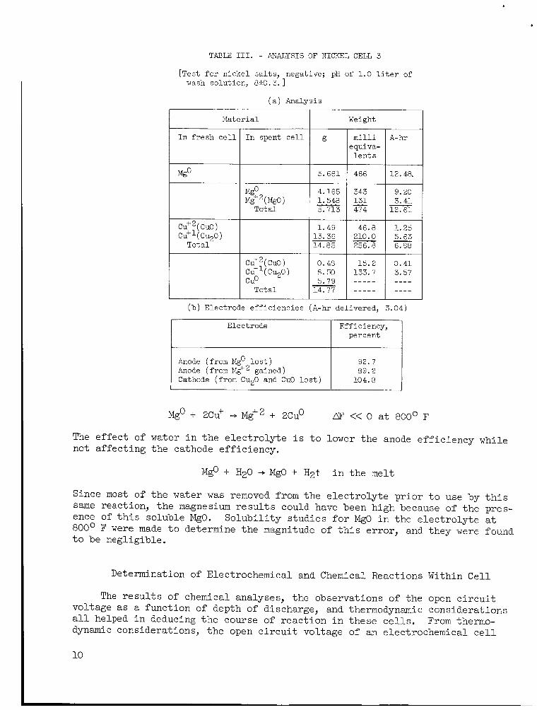
TABLE: 111. - ANALYSIS OF NICKEL CELL 3
[Test f o r n i c k e l s a l t s , negative; pH of 1.0 l i t e r of wash solut ion, 01f.O. 3. 1
( a ) Analysis
Mater i a 1 Weight
5.661
m i l l i equiva-
l e n t s
466 I I I
I Mgo_ 4.165 343
Tota l
12.48. 4 - = I 12.61
CU+Z( CUO) 1.49 46.8 1.25 13.36 210.0 5.63
Tot a 1 14.85 256.8 6.00
CU+2( CUO) 0.48 15.2 0 .41 c u + q CU2O) 0.50 133.7 3.57
5.79 ----- ---- Tota l 14.77 ----- - - - -
- - - c u + q CU2O)
- cue I I I I
( b ) Electrode e f f i c i e n c i e s (A-hr del ivered, 3.04)
Electrode Eff ic iency, percent
Anode (from Mgo l o s t ) 32.7 Anode (from Mg+2 gained) 09.2 Cathode (from CuzO and CuO l o s t ) 104.0
Mgo + ZCu' Mg+2 + Xuo AF << 0 a t 800' F
The effect of water i n the e l ec t ro ly t e i s t o lower the anode ef f ic iency while not affect ing the cathode eff ic iency.
Mgo + H20 + MgO + H2t i n the melt
Since most of the water was removed f r o m t h e e l ec t ro ly t e p r io r t o use by t h i s same reaction, the magnesium r e s u l t s could have been high because of t he pres- ence of t h i s soluble MgO. 800° F were made t o determine the magnitude of t h i s error , and they were found t o be negligible.
Solubi l i ty s tud ies for MgO i n the e l ec t ro ly t e a t
Determination of Electrochemical and Chemical Reactions Within Cel l
The results of chemical analyses, the observations of the open c i r c u i t voltage as a function of depth of discharge, and thermodynamic considerations a l l helped i n deducing the course of reac t ion i n these c e l l s . From thermo- dynamic considerations, the open c i r c u i t voltage of an electrochemical c e l l
10

TAECZ IV. - FREX ENERGY CHANGES AND TIBOFZTICAL
ELECTRODE K)DTENTIALS AT 800' F
Reaction
CUO + Mgg - cuo + Mgo 2cuo + Mgo- cu20 + Mgo cu20 + Mgo + 2cuo + Mgo CUO + Mgo + 2KC1 + K20 + MgClz + Cuo C ~ O + + Z L ~ C ~ -f L ~ ~ O + M ~ C I . ~ + cuo 2CuO + Mgo + 2KC1 + Cu20 + MgClz + K20 Z C ~ O + ~ g 0 + 2 ~ i c 1 + cu20 + + Lizo Cu20 + Mgo + 2KC1 + 2Cuo + MgClz + K20 cu o + I@ + 2Lic1 + ZCUO + ~ g ~ 1 ~ + L ~ ~ O Li20 + MgC12 + Mgo + 2LiC1 K20 + MgC12 + Mgo + ZKC1
?.& + ZLiC1 + MgC12 + 2Li Cuo + ZLiC1 - CuClz + Li20 Cu20 + 2LiC1 + ZCuCl + Li20
2
Mg + 2Kc1+ MgCl2 + 2K
Free energy change, mo
80OoF' k c a l
-103.2 -109.5
-96.4 +18.0 -44.6 +11.4 -51.2 +24.5 -38.1 -57.3
-120.9 +56.5 +50.5
+42.3 +43.5
m e o r e t i c a l open-c i rcu i t
v o l t age,
EeOooOF' V
can be estimated. These estimates are exact i f t h e following c r i t e r i a are met. I
(1) The electrochemical react ion t h a t takes place a t the electrodes i s the same a s the one f o r which the f r e e energy change LP i s being calculated.
( 2 ) The necessary f r e e energy and heat capacity data needed a re avai lable and accurate.
(3) The electrodes a re reversible .
For the system Mg, MgO, CuO, Cu20, Cu, KC1, and LiCl a t 80O0 F, there a re a l imi ted number of react ions t h a t a re thermodynamically f eas ib l e ( t a b l e N).
Three p o s s i b i l i t i e s of the electrochemical reac t ion a re the following:
Mg + 2cuo + Mgo + CUZO LJ?:oo = -109.5 kca l E = 2.37 V (1)
( 2 )
0
Mg + CUO 4 MgO + cu %OO = -103.2 kca l
M g + c u p + Mgo + 2cu Dao0 = -96.4 kca l Eo = 2.09 V ( 3 )
Eo = 2.24 V 0
A s mentioned i n General Charac te r i s t ics of t he C e l l , an e f f o r t was made t o determine the s o l u b i l i t y of MgO i n the eu tec t ic melt a t 800' F. The results of these experiments showed t h a t 2.68x10⁻³ gram of MgO per gram of e u t e c t i c was t h e l i m i t of s o l u b i l i t y of MgO. Once t h i s number was known, an estimate of the
11

f r ee energy change of t h e following reac t ion could be a r r ived a t .
Mg" + 0" += MgO a t 800' F
m0 = -RT I n K
where
KFo
R universal gas constant
T absolute temperature, %
K equilibrium constant
standard s t a t e f r e e energy change
Since d i lu te solut ions were employed, t he a c t i v i t i e s a of the ions were as- sumed t o be equal t o the mole f rac t ions , and the a c t i v i t y of the s o l i d aMgO was taken t o be unity. The AI?' of t h e reac t ion was calculated t o be -15.7 k i loca lor ies and theo re t i ca l open c i r c u i t voltage 0.34 volt . Reactions (l), ( 2 ) , and (3 ) assume t h a t MgO i s formed electrochem- i ca l ly . t he following type of reac t ion w i l l r e su l t :
Eo equivalent t o t h i s was
However, by subtract ing the reac t ion f o r the chemical formation of MgO,
Mg + cuzO += Mgo + 2cu
l e s s 0 -2 + Mg" += MgO.1 = -15.7 kca l @ZOOOF
= -80.7 kca l %oo Mg + CU 0 + 2Cu + Mg+2 + O-' 2
This correction can be applied t o the other two reactions, and the following theo re t i ca l open c i r c u i t voltages w i l l r e su l t :
Reaction (1) :
2.37 - 0.34 = 2.03 V
Reaction ( 2 ) :
Reaction ( 3) :
1 2
2 .24 - 0.34 = 1.90 V
2.09 - 0.34 = 1.75 V

A possible side react ion of t he type
0 E = 1.11 V M ~ O + zLic1+ C ~ O -, ~ g c 1 ~ + L i o + 2cu = -51.2 kca l 2
w a s not considered very l i k e l y considering the and 3. If the reac t ion products underwent no fu r the r reaction, have been present i n t h e analysis sample:
D o ' s of the react ions 1, 2, would
Although @(OH) t i o n i n the ce l f cannot be completely discounted. t h e r chemical reaction, which would have removed these i n i t i a l products of reac t ion
was found not t o be present (X-ray analysis) , t h i s s ide reac- There could have been a fur-
0 @C12 + Li20 -+ MgO + ZLiC1 D'800 = -57.3 kca l
Other possible s ide reac t ions involving the electrodes or e lectrode reac- . t ion products with the e l ec t ro ly t e a l l have large pos i t ive f r e e energy changes ( t a b l e IV, p. 11).
2KC1 + rySg + MgC12 + 2K LPgooq = +56.5 kca l
CuO + 2LiC1 + CuC12 + Li20 = +42.3 kcal
They were not considered s igni f icant i n these ce l l s .
The results of the chemical analysis showed t h a t the oxidized magnesium i n the spent c e l l s was present a s MgO, and the cathodes were reduced f i n a l l y t o copper metal. The analysis d id not indicate, however, whether cupric oxide was reduced d i r e c t l y t o copper o r intermedially t o cuprous oxide, which w a s f u r t h e r reduced. anolyte and catholyte, t h a t is, both magnesium ion and oxide ion were mobile i n the e lec t ro ly te .
The U-shaped-cell experiment showed t h a t MgO was formed both i n the
From t he previous information, the following statements were postulated concerning the pr inc ipa l electrochemical and chemical react ions t h a t took place within the ce l l s . A t t he anode, the magnesium w a s oxidized t o magnesium ions,. I n the anoly-be some of the magnesium ions were prec ip i ta ted by oxide ions. A t t he cathode, t he mixed oxides were reduced f i n a l l y t o copper metal and cxide ions. I n t he catholyte some of the oxide ions were prec ip i ta ted by magnesium ions.
Reactions 1 t o 3 corrected f o r t h e nonelectrochemical formation of MgO pre- d i c t open c i r c u i t voltages of 2.03, 1.90, and 1.75 vol t s , respectively. voltages a re g rea t e r than found i n these studies. no obvious explanation of it can be seen.
These This difference i s la rge and
1 3

1 . 6 ~
1.
> 6 1. 2 0
m > c
.- c
1. z w 1. c U m -
Figure 7. - Plot of terminal voltage against current for nickel cell 3. Dashed lines show lines generated on x-y plotter for 1000° F.
Dynamic Charac te r i s t ics
(a) After 4 hours of load.
No-load voltage
Voltage across
8 ' Time
(bl After 120 hours of load.
Figure 8. - Load and no-load voltage traces of intermit- tently operated glass cell.
Some dynamic cha rac t e r i s t i c s of these c e l l s were obtained t o gain some ins ight not only i n t o the electrode character is- t i c s , but also i n t o the i n t e r n a l r e s i s - tance of these ce l l s . ( E - I ) p lo t s ( f ig . 7 ) were made of these cha rac t e r i s t i c s on n icke l c e l l 3 using an x-y p l o t t e r i n conjunction with an elec- t r i c a l c i r c u i t as depicted i n f igure 4 (p. 5) . i s p lo t ted i n the y-direct ion concurrently with a measure of the currents passing through the c e l l i n t he x-direction. The no-load voltage of the c e l i i s t he point along the y-axis a t a condition of zero current passage. The s t r a i g h t l i n e s of f igure 7 a r e ac tua l ly averages of t he l i n e made on t h e upswing and the l i n e made on the downswing, The l i n e s made going from no-load voltage t o short c i r c u i t current were a maximum of about 0 . 2 ampere higher (dot ted l i n e s ) than the r e tu rn l i n e going
Voltage current
The terminal voltage of t he c e l l
14

from short c i r c u i t current back down t o no-load conditions. The ac tua l data f o r t he E- I p lo t a t 1000° F i s shown i n f igure 7. un i t s of ohms and i s a measure of the t o t a l i n t e rna l res is tance of the ce l l . The pos i t ion of the l i n e near where it crosses the x-axis depends upon the length of time needed t o generate the l ine . a t a high ra te , the concentration polar izat ion e f f e c t s w i l l cause the l i n e t o drop towards lower currents. An attempt was made t o take a uniform amount of time t o construct these E-I p lo t s (about 10 sec). c e l l decreased from a value of 0.52 ohm a t 80O0 F t o 0.37 ohm a t 1000° F. f a c t was t o be expected i n t h a t t he higher temperatures lead t o higher values of t he ion mobil i t ies .
The slope of t h i s l i n e has the
If a c e l l i s allowed t o discharge
The t o t a l res i s tance of t h i s This
Reproductions of the ac tua l time-voltage t r a c e s of t he g l a s s c e l l appear i n f igure 8. of time needed f o r the c e l l voltage t o adjust once the load has e i t h e r been switched on o r off . Concentration polarization i s more pronounced i n a f r e sh c e l l than i n the c e l l f i l l e d with products of reac t ion (deeply discharged).
The polar izat ion caused by ion depletions i s measured by the length
CONCLUSIONS
A long- l i fe thermal c e l l was b u i l t following ce r t a in guidelines. One of the c e l l s t h a t was discharged over a period of 6 days f a i l e d when the anode be- came disconnected. and i n no way r e f l e c t s t he ultimate periods o f usefulness of t h i s type of ce l l . A d i f f e ren t anode design would enable more of t he useful energy t o be withdrawn from the c e l l . The self-discharge charac te r i s t ics of the c e l l a re what limits the period of usefulness. The c e l l t h a t was discharged over a period of 6 days had an anode ef f ic iency of 73 percent, which shows t h a t 27 percent of the anode e i t h e r f laked off , was consumed by i n t e r n a l discharge reactions, or reacted with the impure e l ec t ro ly t e during the 6 days of operation. It i s f e l t t h a t b e t t e r s a l t drying techniques w i l l improve t h i s number. The wide operating temperature range of from about 670° t o about 1200' F would make it a useful c e l l f o r some ant ic ipa ted space applications. The open c i r cu i t voltage of 1.55 v o l t s was low- e r than expected from thermodynamic considerations. It was concluded t h a t the following reac t ions took place a t the electrodes. A t the cathode, the copper oxides were reduced t o metal l ic copper with oxide ions being l i be ra t ed i n t o the e lec t ro ly te . ions. cathode and anode. The excess magnesium ions near t h e anode and the excess ox- ide ions near t h e cathode exceeded the so lubi l i ty l i m i t of t h e s l i g h t l y soluble magnesium oxide.
This type of f a i l u r e was prevalent during this invest igat ion
A t the anode, the magnesium was oxidized t o soluble magnesium Insoluble magnesium oxide w a s found t o form i n the region of both the
Lewis Research Center, National Aeronautics and Space Administration,
Cleveland, Ohio, March 16, 1965.
15

REFERENCES
1. Vinal, G. W. : Primary Bat te r ies . John Wiley & Sons, Inc., 1950, pp. 324- 329.
2. Goodrich, R. B.; and Evans, R. C. : Thermal Bat te r ies . Electrochem. SOC., vol. 99, no. 8, Aug. 1952, pp. 207-208.
3. McKee, E. : Thermal Cells. Proc. Tenth Annual Bat tery Res. and Dev. Conf., Power Sources Div., Signal Corps Eng. Labs., Fort Monmouth ( N . J . ) , 1956, pp. 26-28.
4. Laitinen, H. A.; and Liu, C. H. : A n Elec.tromotive-Force Ser ies i n Molten Lithium Chloride-Potassium Chloride Eutectic. J. Am. Chem. Soc., vol. 80, 1958, pp. 1015-1020.
5. Laitinen, H. A.; and Bhatia, B. B. : Electrochemical Study of Metal l ic Oxides i n Fused Lithium Chloride-Potassium Chloride Eutectic. J. Electrochem. SOC., V O ~ . 107, 1960, pp. 705-710.
6. Sel is , Sidney M.; McGinnis, Laurence P.; McKee, Elmer S.; and Smith, James T.: Electrode Reactions and I ron Oxide Select ion f o r t he Thermal Cell Mg/LiC1-KC1/FeOx,Ni. J. Electrochem. SOC., vol. 110, no. 6, June 1963, pp. 469-476.
7. Laitinen, H. A.; Ferguson, W. S.; and Osteryoung, R. A.: Preparation of Pure Fused Lithium Chloride -Pot ass i u m Eut e c t i c Solvent . J . E l e c t roc hem. Soc., vol. 104, no. 8, Aug. 1957, pp. 516-520.
8. Schwarzenbach, G. : Complexometric Ti t ra t ions . In t e r sc i . Pub. 1957, p. 62.
1 6 NASA-Langley, 1965 E- 2800