nasa technical note - ufprftp.demec.ufpr.br/cfd/bibliografia/propulsao/1968... · tum equation for...
TRANSCRIPT
NASA TECHNICAL NOTE
LAMINARIZATION OF A TURBULENT BOUNDARY LAYER AS OBSERVED FROM HEAT-TRANSFER AND BOUNDARY-LAYER MEASUREMENTS IN CONICAL NOZZLES
by Donald R. Boldman, James F. Schmidt, and Anne K . GaZZugher
Lewis Research Center CZeveZand, Ohio
N A T I O N A L AERONAUTICS A N D SPACE A D M I N I S T R A T I O N W A S H I N G T O N , D. C. 0 SEPTEMBER 1968
.- X I ,
v NASA T N D-4788
J Y
LAMINARIZATION OF A TURBULENT BOUNDARY LAYER AS OBSERVED ( 1 4
FROM‘HEAT-TRANSFER AND BOUNDARY- LAYER
MEASUREMENTS IN CONICAL NOZZLES
By Donald R. Boldm+A James F,. Schmidt , a n d Anne K. Gal l aghe r
L e w i s R e s e a r c h C e n t e r Cleveland, Ohio
/’ -./-- Wd> -
NATIONAL AERONAUTICS AND SPACE ADMJf+Hf&4T4ON ~-
For sale by the Clearinghouse for Federal Scientific and Technical Information Springfield, Virginia 22151 - CFSTI price $3.00
I ' -
ABSTRACT
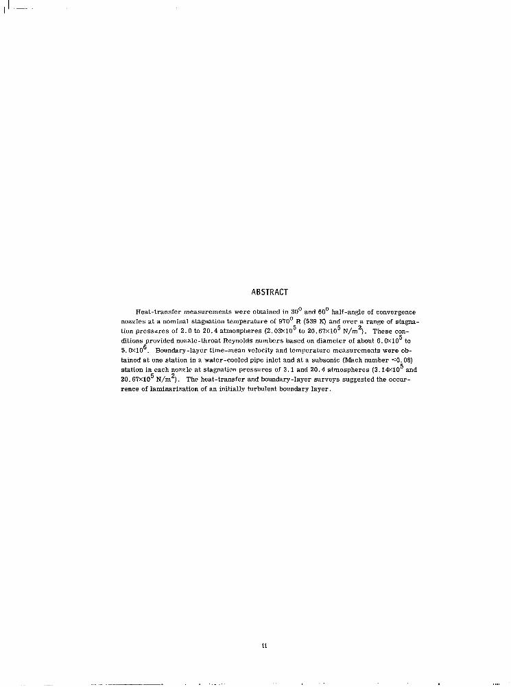
Heat-transfer measurements were obtained in 30' and 60' half-angle of convergence nozzles at a nominal stagnation temperature of 970' R (539 K) and over a range of stagna- tion pressures of 2 .0 to 20.4 atmospheres (2. 03X105 to 2 0 . 6 7 ~ 1 0 ~ N/m2). These con- ditions provided nozzle-throat Reynolds numbers based on diameter of about 6.0X10⁵ to 5. 0X106. Boundary-layer time-mean velocity and temperature measurements were ob- tained a t one station in a water-cooled pipe inlet and a t a subsonic (Mach number 50.08) station in each nozzle a t stagnation pressures of 3.1 and 2 0 . 4 atmospheres (3. l&105 and 2O.67X1O5 N/m2). The heat-transfer and boundary-layer surveys suggested the occur- rence of laminarization of an initially turbulent boundary layer.
ii
. .

.
LAMINARIZATION OF A TURBULENT BOUNDARY LAYER A S OBSERVED FROM HEAT-
TRANSFER AND BOUNDARY-LAYER MEASUREMENTS IN CONICAL NOZZLES
by Donald R. Boldman, James F. Schmidt, and A n n e K. Gallagher
Lewis Research Center
SUMMARY
Heat-transfer measurements were obtained in 30' and 60' half-angle of convergence nozzles at a nominal stagnation temperature of 970' R (539 K) and over a ran e of stagna- tion pressures of about 2.0 to 20.4 atmospheres (2.03X10 to 20.67XlO N/m ) . These conditions provided nozzle-throat Reynolds numbers based on diameter of about 6 . 0 ~ 1 0 to 5. OX106. Time-mean boundary-layer velocity and temperature measurements were obtained at one station in a water-cooled pipe inlet and a t a subsonic (Mach number S O . 08) station in each nozzle at stagnation pressures of 3 .1 and 20.4 atmospheres ( 3 . 1 4 ~ 1 0 and 20.67XlO N/m ) . A t these pressure levels, the thermal and velocity boundary layers in the pipe inlet were conventional for turbulent pipe flow.
The heat transfer at a given station in the nozzles generally exhibited two distinct de- pressions from the predicted levels based on a turbulent pipe flow type of correlation. The larger of these depressions occurred a t lower Reynolds numbers and was assumed to be the result of laminarization of the initially turbulent boundary layer. The smaller of these depressions, which occurred at higher Reynolds numbers, was assumed to be the result of reduced turbulent transport associated with a turbulent boundary layer in an ac- celerating flow.
of conditions in the low Reynolds number range. These profiles were described by a power law which is often associated with laminar flow. Although absolute confirmation of laminarization cannot be established on the basis of time-mean surveys, the laminar-type velocity profile provides evidence in support of the laminarization postulate. In progres- sing towards the throat of each nozzle, the heat t ransfer at the low Reynolds number con- dition approached a classical laminar flow level, thus lending additional support to the feasibility of laminarization.
tum equation for axisymmetric flow assuming flat-plate boundary-layer transition cr i ter ia and a n empirical relation for the shear stress, form factor, and velocity gradient. The crit ical acceleration parameter, which was within the range of values reported by others, provided a fair definition of the regions of low and high depressions in the heat transfer in the two nozzles.
5 5 8 5
5 5 2
A time-mean boundary-layer velocity profile was obtained in each nozzle at one set
A critical value of the acceleration parameter was derived from the integral momen-
IN TRO DUCT ION
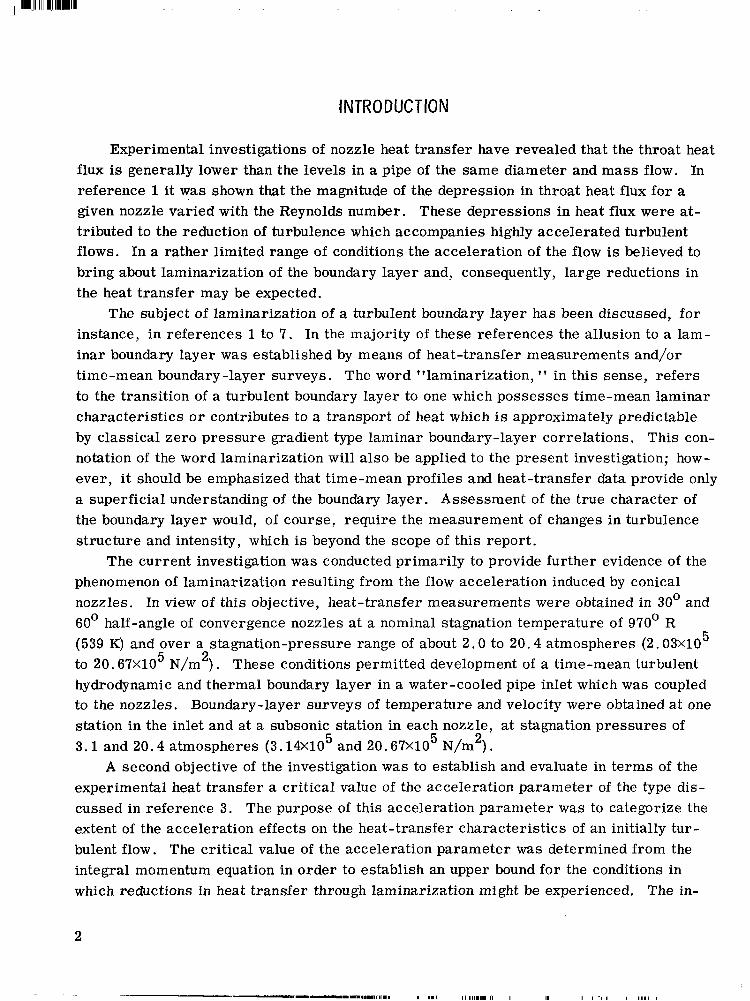
Experimental investigations of nozzle heat transfer have revealed that the throat heat flux is generally lower than the levels in a pipe of the same diameter and mass flow. In reference 1 it was shown that the magnitude of the depression in throat heat flux for a given nozzle varied with the Reynolds number. These depressions in heat flux were at- tributed to the reduction of turbulence which accompanies highly accelerated turbulent flows. In a rather limited range of conditions the acceleration of the flow is believed to bring about laminarization of the boundary layer and, consequently, large reductions in the heat transfer may be expected.
The subject of laminarization of a turbulent boundary layer has been discussed, for instance, in references 1 to 7. In the majority of these references the allusion to a lam- inar boundary layer was established by means of heat-transfer measurements and/or time-mean boundary -layer surveys. The word "laminarization, 1 T in this sense, refers to the transition of a turbulent boundary layer to one which possesses time-mean laminar characterist ics o r contributes to a transport of heat which is approximately predictable by classical zero pressure gradient type laminar boundary-layer correlations, This con- notation of the word laminarization will also be applied to the present investigation; how- ever, it should be emphasized that time-mean profiles and heat-transfer data provide only a superficial understanding of the boundary layer. Assessment of the t rue character of the boundary layer would, of course, require the measurement of changes in turbulence structure and intensity, which is beyond the scope of this report .
The current investigation was conducted primarily to provide further evidence of the phenomenon of laminarization resulting from the flow acceleration induced by conical nozzles. In view of this objective, heat-transfer measurements were obtained in 30' and 60' half-angle of convergence nozzles at a nominal stagnation temperature of 970' R
5 (539 K) and over a stagnation-pressure range of about 2.0 to 20.4 atmospheres (2.03XlO to 20.67~10 N/m ) . These conditions permitted development of a time-mean turbulent hydrodynamic and thermal boundary layer in a water-cooled pipe inlet which was coupled to the nozzles. Boundary-layer surveys of temperature and velocity were obtained at one station in the inlet and at a subsonic station in each nozzle, at stagnation pressures of 3 .1 and 20.4 atmospheres (3.14X10 and 20.67X10 N/m ) .
experimental heat transfer a critical value of the acceleration parameter of the type dis- cussed in reference 3. The purpose of this acceleration parameter was to categorize the extent of the acceleration effects on the heat-transfer characterist ics of an initially tur - bulent flow. The critical value of the acceleration parameter was determined from the integral momentum equation in order to establish an upper bound for the conditions in which reductions in heat transfer through laminarization might be experienced. The in-
5 2
5 5 2
A second objective of the investigation was to establish and evaluate in te rms of the
2

tegral momentum equation contained certain empiricisms which differed from those of reference 3 but presumably were more compatible with the accelerating flow in conical nozzles.
SYMBOLS
A
r
St
T
t
U
X
Y
Y
z
r A
6
area
constants
dia m et er
boundary-layer form factor, H = 6 / e
enthalpy
acceleration parameter
Mach number
pres s u r e
Prandtl number
local heat flux
Reynolds number
radius
Stanton number
temperature
temperature on heat-flux meter
velocity
distance along wall
distance along heat-flux meter measured from gas-side wall
distance normal to the wall
axial coordinate measured from inlet boundary-layer survey station
velocity-gradient parameter given by eq. (B4)
thermal boundary-layer thickness
vel0 ci ty boundary - laye r thickness
*
3
. . ..

I '
6*
E
e
EL
V
P
7
compressible boundary-layer displacement thickness, 6 =
shear-s t ress parameter given by eq. (B3) * J, (1
compressible boundary-layer momentum thickness, 8 E (1 - t ) d y pco'co
dynamic viscosity
kinematic viscosity
density
shear s t r e s s
Subscripts:
ad
ax
C
c r
D
i
Pf
ref
S
t
W
8
co
0
adiabatic wall condition
axisymmetric
curvature of nozzle throat
critical value establishing boundary-layer transition
based on diameter
inlet
turbulent pipe flow
reference enthalpy condition
freestream static condition
local stagnation condition
wall condition
based on momentum thickness
f rees t ream
stagnation condition
Superscript :
* geometric throat of nozzle
4
1 .. ~ .....-. . ......-.. 1.1-...-1-.,_._.....-,..,... ..... ... 111.1.1 111.1.11 111,111,. I I. ,I I I ,,,

APPARATUS AND 1NSTRUMENTATlON
I in. I cm I in.
1 -18.98 6.50 16.51 0 2 11.648 5.092 12.934 13.218 3 6.952 3.934 . 9.992 14.221 4 5.591 3.528 8.961 14.575 5 4.395 3.128 7.945 14.921 6 3.328 2.722 6.914 15.273 7 2.410 2.316 5.883 15.623 8 1.392 1.760 4.470 16.120 9 1.024 1.510 3.835 16.558 10 1.000 1.492 3.790 16.733
The heat-transfer facility, boundary-layer probes, heat-flux meters , and nozzles used in this investigation have been described in references 8 to 10. An important dif- ference between the hardware used in the present study and that previously reported con- cerns the pipe inlet configuration. The inlets used in the experiments of references 8 to 10 were uncooled; however, in the present investigation a water-cooled inlet was used. Pertinent details of the design of the inlet, as well as a condensed description of the pre- viously reported apparatus and instrumentation, are presented herein.
The test configurations consisted of a 6.5-inch-diameter (16.5-cm-diam) by 37.59- inch-long (95.48-cm-long) pipe inlet coupled to water-cooled 30' and 60' half-angle of convergence by 15' half-angle of divergence conical nozzles as shown in figures 1 and 2, respectively. Hereinafter, these nozzles will be identified by their convergence half -
cm
0 33.574 36.121 37.021 37.899 38.793' 39.682 40.945 42.057 42.502
Station 1
I- -25.59 in. (65.00 cm) -4 1-
I 1 1 ) I Boundarv-laver b -12.18 in. --+ 1 ! I ./
4.737 (12.032 in. cm) $,\j LrC = 2.0 r*
- - CD-9825-12 -37.59 in. (95.48 cm)
5
Station
25.59 in. (65.00 an-----
_ _ _ ~ _ _ _ _ _ _ . FI
?I- 37.59 in. (95.48 cm)- \
Station Area ratio, Diameter, D Axial distance, z _- -_
A/A* - in. cm in. cm
0 9.352 4.584 11.643 12.548 31.872 7.769 4.178 10.612 12.665 32.169 6.299 3.762 9.555 12.785 32.474 3.322 2.732 6.939 13.094 33.259
6 2.373 2.309 5.865 13.280 33.731 7 1.341 1.736 4.409 13.719 34.846
1.023 1.516 3.851 14.154 35.951 9 1.000 1.499 3.807 14.300 36.322
CD-9826-12
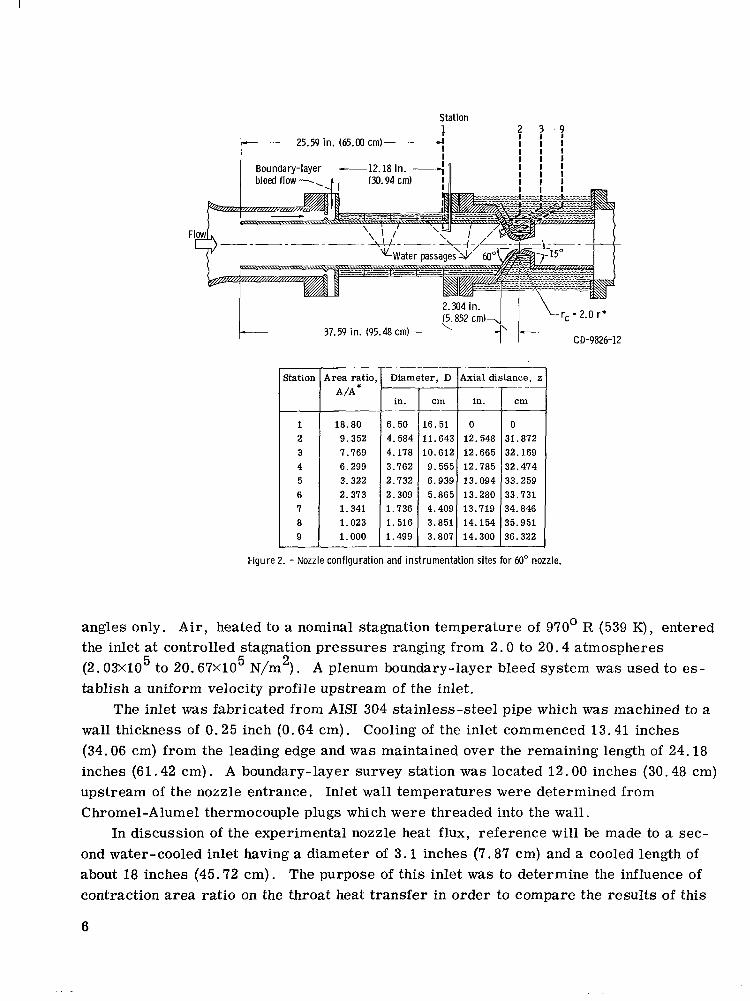
Figure 2. - Nozzle configuration and instrumentation sites for 60" nozzle.
angles only. Air , heated to a nominal stagnation temperature of 970' R (539 K), entered the inlet at controlled stagnation pressures ranging from 2 . 0 to 20.4 atmospheres (2.03x10 to 20.67X10 N/m ) . A plenum boundary-layer bleed system was used to es- tablish a uniform velocity profile upstream of the inlet.
The inlet was fabricated from AIS1 304 stainless-steel pipe which was machined to a wall thickness of 0.25 inch (0.64 cm). Cooling of the inlet commenced 13.41 inches (34.06 cm) from the leading edge and was maintained over the remaining length of 24.18 inches (61.42 cm) . A boundary-layer survey station was located 12.00 inches (30.48 cm) upstream of the nozzle entrance. Inlet wall temperatures were determined from Chromel-Alumel thermocouple plugs which were threaded into the wall.
ond water-cooled inlet having a diameter of 3 .1 inches (7.87 cm) and a cooled length of about 18 inches (45.72 cm). The purpose of this inlet was to determine the influence of contraction area ratio on the throat heat transfer in order to compare the results of this
5 5 2
In discussion of the experimental nozzle heat flux, reference will be made to a sec-
6

investigation with the experiment of reference 11. Such a comparison was desirable since the nozzle used in reference 11 was geometrically s imilar to the present nozzle, and operating conditions were nearly the same. The method of heat-flux measurement in reference 11 differed from that of the present experiment.
The heat- transfer data in this investigation were obtained at nine measuring stations in the 30°nozzle and at eight stations in the 60' nozzle (refer to figs. 1 and 2, respectively). An Inconel heat-flux meter of the type described in reference 8 and a wall static pressure tap were located at each station in the nozzle. The 30' nozzle contained a boundary-layer survey station with an area ratio of 6.952 (station 3), which corresponds to a Mach num- ber of about 0.08. A boundary-layer survey station with an area ratio of 7.769 (station 3) was located in the 60' nozzle. The Mach number at the 60' nozzle survey station was nominally 0 .05 (based on the experimental p ressure ratio and isentropic flow).
ing a rectangular opening 0.002 inch (0.0051 cm) high by 0.030 inch (0.0762 cm) wide. The boundary-layer temperature profile was measured in the plane of the kinetic-head measurements by means of a probe containing a bare-junction Chromel-Alumel thermo- couple. The diameter of the junction was 0.005 inch (0.0127 cm). References 7 and 8 should be consulted for further details concerning the design of the boundary-layer probes.
by precision motorized actuators geared to linear potentiometers. Probe contact with the wall was established by means of an electrical short circuit. A *O. l-percent linearity of the potentiometers allowed for position measurements within *O. 002 inch (*O. 0051 cm) for the temperature probes and the inlet pressure probe. Based on the actuator linearity, position measurements for the pressure probe in each nozzle were within +O. 0005 inch (*O. 0013 cm). Unidirectional t raverses were made in order to minimize e r r o r s due to gear play. Potential e r r o r s in displacement resulting from thermal distortion of the tip geometries and recording technique are expected to be within the values determined from the linearity of the actuators.
were monitored on the X-Y recorder .
The boundary-layer kinetic-head measurements were obtained with a pitot probe hav-
The pressure and temperature probes were driven in a direction normal to the wall
The output signals from both the pressure and temperature boundary-layer probes
DATA REDUCTION
Local Heat Flux
The local heat f lux q was computed from the observed temperature gradient in the heat-flux meters. The temperature gradient in the meters can be described by the
7
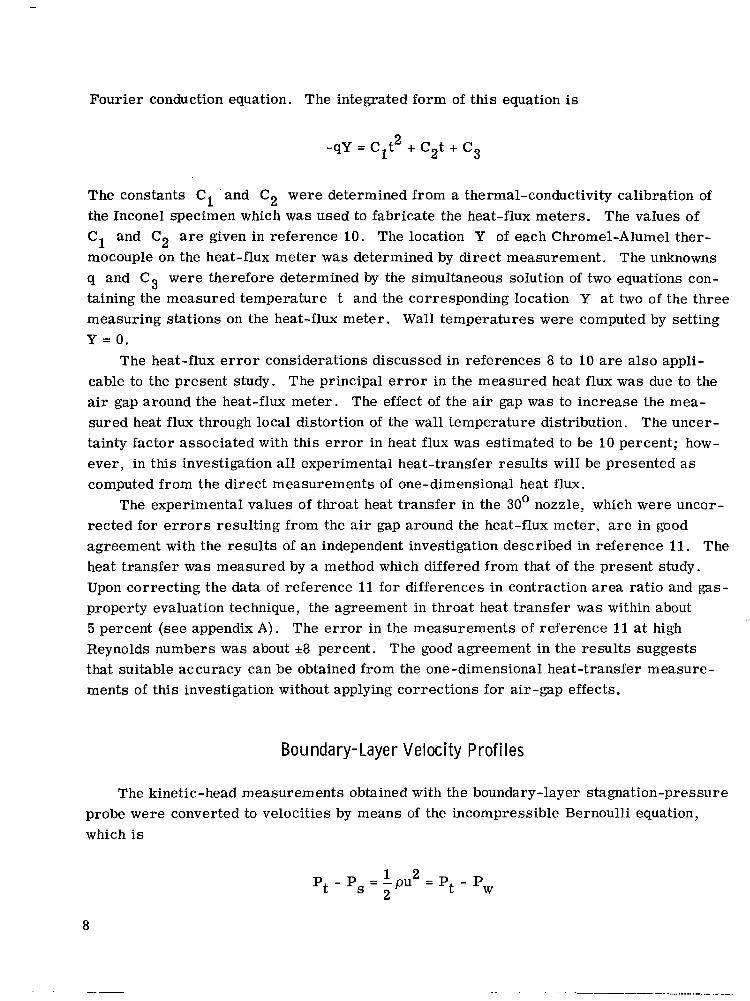
Fourier conduction equation. The integrated form of this equation is
2 -qY = Clt + C2t + c3
The constants C1 ' and C2 were determined from a thermal-conductivity calibration of the Inconel specimen which was used to fabricate the heat-flux meters. The values of C1 and C2 are given in reference 10. The location Y of each Chromel-Alumel ther- mocouple on the heat-flux meter was determined by direct measurement. The unknowns q and C3 were therefore determined by the simultaneous solution of two equations con- taining the measured temperature t and the corresponding location Y at two of the three measuring stations on the heat-flux meter. Wall temperatures were computed by setting Y = O .
The heat-flux e r r o r considerations discussed in references 8 to 10 a r e also appli- cable to the present study. The principal e r r o r in the measured heat flux was due to the air gap around the heat-flux meter. The effect of the air gap was to increase the mea- sured heat flux through local distortion of the wall temperature distribution. The uncer- tainty factor associated with this e r r o r in heat flux was estimated to be 10 percent; how- ever, in this investigation all experimental heat-transfer results will be presented as computed from the direct measurements of one-dimensional heat flux.
rected for e r r o r s resulting from the air gap around the heat-flux meter, are in good agreement with the resul ts of an independent investigation described in reference 11. The heat transfer was measured by a method which differed from that of the present study. Upon correcting the data of reference 11 for differences in contraction a rea ratio and gas- property evaluation technique, the agreement in throat heat transfer was within about 5 percent (see appendix A ) . The e r ro r in the measurements of reference 11 at high Reynolds numbers was about rt8 percent. The good agreement in the results suggests that suitable accuracy can be obtained from the one-dimensional heat-transfer measure- ments of this investigation without applying corrections for air-gap effects.
The experimental values of throat heat transfer in the 30' nozzle, which were uncor-
Bo u nda r y- La ye r V e I oc i t y P r of i I es
The kinetic-head measurements obtained with the boundary-layer stagnation-pressure probe were converted to velocities by means of the incompressible Bernoulli equation, which is
1 2 t - pw P - P = - p u = p
s 2
8
The local density p evolved from the perfect gas law in which the measured wall static pressure and local stagnation temperature were. the principal input. In this formulation, the local static pressure was assumed to equal the observed wall static pressure. The static temperature was assumed equal to the local stagnation temperature (Ts = Tt) be- cause the maximum Mach number M at a survey station was quite low (M 5 0.08).
The boundary-layer velocity profiles will be presented in te rms of the velocity ratio u/uw and a nondimensional distance parameter y/6. The free-stream velocity uw was determined from the maximum value of the kinetic-head measurements. Discussion of the method used to obtain the velocity boundary-layer thickness 6 will be deferred until the profiles are presented in the section entitled RESULTS.
Bou nda ry-Layer Temperature Prof i I es
The thermocouples in the temperature probes were referenced to the plenum temper- ature, and the resulting differential signal was recorded. In reducing the temperature data the assumptions of negligible probe heat losses and a temperature recovery factor of 1 .0 were employed. The latter assumption is valid since probe measurements were limi- ted to very low Mach numbers.
temperature-difference ratio (Tt - Tw)/(To - Tw) and a nondimensional distance param- eter y/A. The thermal boundary-layer thickness A was equal to the distance from the wall corresponding to a temperature-difference ratio of 0.99.
Boundary-layer temperature distributions will be presented in te rms of the
RESULTS
Axisymmetric Acceleration Parameter
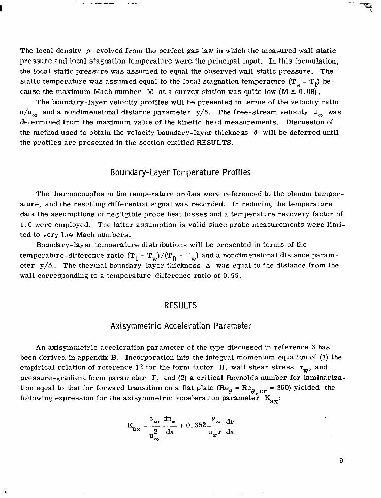
An axisymmetric acceleration parameter of the type discussed in reference 3 has been derived in appendix B. Incorporation into the integral momentum equation of (1) the empirical relation of reference 12 for the form factor H, wall shear stress T ~ , and pressure-gradient form parameter r, and (2) a critical Reynolds number for laminariza- tion equal to that for forward transition on a flat plate (Reg = Reg, cr = 360) yielded the following expression for the axisymmetric acceleration parameter Kax:
vw duo0 '03 d r + 0.352- - u w r dx
- Kax -
u o O
9
la
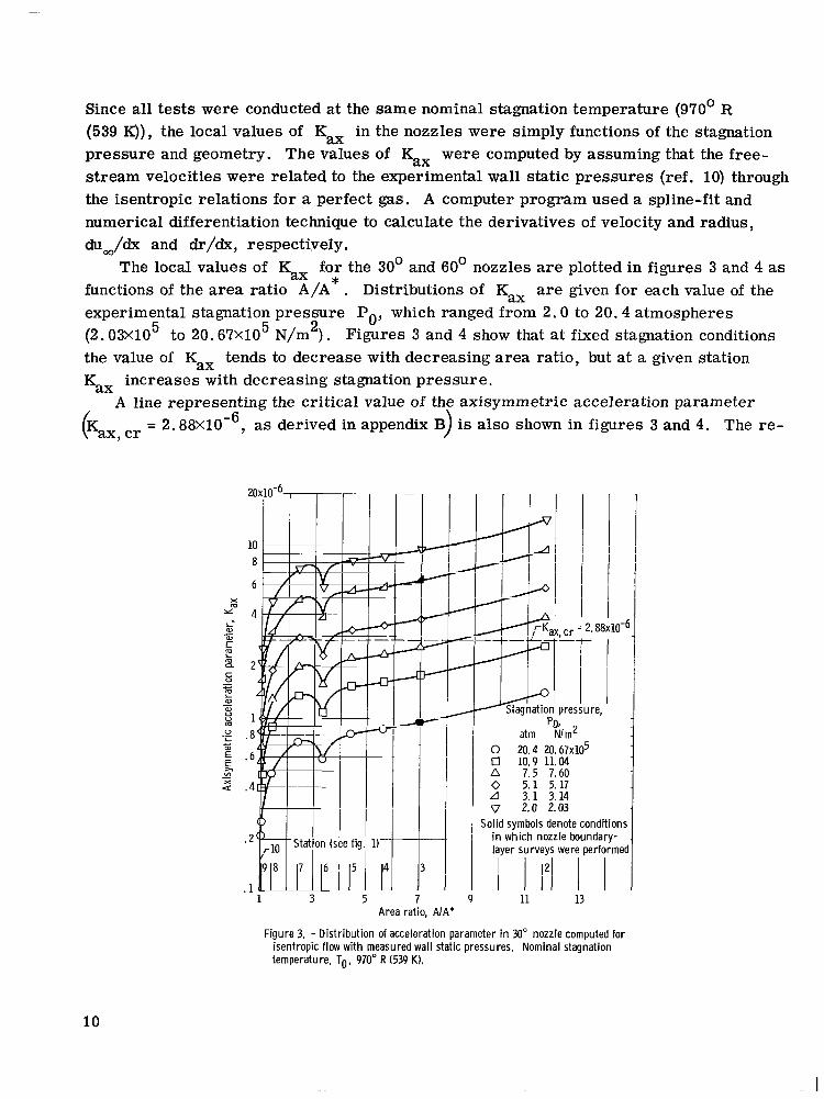
Since all tests were conducted at the same nominal stagnation temperature (970' R (539 K)), the local values of Kax in the nozzles were simply functions of the stagnation pressure and geometry. The values of Kax were computed by assuming that the free- s t ream velocities were related to the experimental wall static pressures (ref. 10) through the isentropic relations for a perfect gas. A computer program used a spline-fit and numerical differentiation technique to calculate the derivatives of velocity and radius, chz,/dx and d r / d x , respectively.
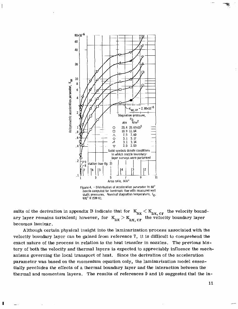
functions of the area ratio A/A . Distributions of Kax are given for each value of the experimental stagnation pressure Po, which ranged from 2.0 to 20.4 atmospheres ( 2 . 0 3 ~ 1 0 ~ to 2 0 . 6 7 ~ 1 0 ~ N/m2). Figures 3 and 4 show that at fixed stagnation conditions the value of Kax tends to decrease with decreasing area ratio, but at a given station Kax increases with decreasing stagnation pressure.
A line representing the critical value of the axisymmetric acceleration parameter
@ax, c r
The local values of Kax for the 30' and 60' nozzles are plotted in figures 3 and 4 as *
= 2 . 8 8 ~ 1 0 - ~ , as derived in appendix B) is also shown in figures 3 and 4. The r e -
I
f
!
I
I 1
cr = 2. -r e/ PO. preslure,
atm N/m2 0 20.4 2 0 . 6 7 ~ 1 0 ~ 0 10.9 11.04 A 7.5 7.60 0 5.1 5.17 A 3. 1 3.14
2.0 2.03 Solid symbols denote conditions
in which nozzle boundary- laver survevs were Derformed
7 9 11 13 Area ratio, A/A*
Figure 3. - Distribution of acceleration parameter in 30" nozzle computed for isentropic flow with measured wall static pressures. Nominal stagnation temperature, To, 970" R (539 K).
10
.I
80
60
40
20
x 10 8 2
- 6 i
E m - E 4 co .- I m L al
(I) U -
u 2
E, .- v , 1 z .a
U L c 0)
.- E
.6
. 4
.2
.1
0 20.4 20.67~10~ 0 10.9 11.04 A 7.5 7.60 0 5. 1 5. 17 A 3. 1 3. 14 v 2.0 2.03
3 5 7 9 11 Area ratio, A/A*
Figure 4. - Distribution of acceleration parameter in 60" nozzle computed for isentropic flow with measured wall static pressures. Nominal stagnation temperature, To, 970" R (539 K).
sults of the derivation in appendix B indicate that for Kax < Kax, cr the velocity bound- a ry layer remains turbulent; however, for Kax becomes laminar.
Although certain physical insight into the laminarization process associated with the velocity boundary layer can be gained from reference 7, it is difficult to comprehend the exact nature of the process in relation to the heat transfer in nozzles. The previous his- tory of both the velocity and thermal layers is expected to appreciably influence the mech- anisms governing the local transport of heat. Since the derivation of the acceleration parameter was based on the momentum equation only, the laminarization model essen- tially precludes the effects of a thermal boundary layer and the interaction between the thermal and momentum layers. The resul ts of references 9 and 10 suggested that the in-
the velocity boundary layer > Kax, c r
11
_..I

teraction between the layers might be weak. A knowledge of the thermal boundary layer (energy-calculation method) was sufficient to yield reasonably good predictions of nozzle heat transfer. In view of the possible importance of the thermal boundary layer, a straightforward application of the acceleration parameter in quantitatively assessing the nozzle heat transfer does not appear feasible.
(fig. 3) indicate that the veloci? boundary layer at Po = 20.4 and 10.9 atmospheres (20.67X10 and 11. O&105 N/m ) should be characteristically turbulent. However, at Po < 7 . 5 atmospheres (7.60X10 N/m ), the velocity boundary layer should experience laminarization. The extent of the laminarization increases with decreasing pressure level. For instance, at Po = 2.0 atmospheres (2.03X10 N/m ), Kax is greater than
a t all stations except in the vicinity of the throat. In this case a predominantly Kax, c r laminar boundary-layer history is expected to influence the heat exchange at the throat. Since history considerations cannot be dismissed, the throat values of Kax which were less than Kax,cr do not necessarily imply the existence of a turbulent velocity boundary layer at the throat. This same argument can be applied to the distributions of Kax for the 60' nozzle (fig. 4).
that the steeper convergence angle of the 60' nozzle tends to induce laminarization over a wider range of conditions. This is most apparent at the highest stagnation pressures (Po = 20.4 and 10.9 atm; 20 .67~10 and 11.04X10 N/m ) . The results in figure 3 in-
Based on the laminarization criterion, the distributions of Kax for the 30' nozzle
5 5 2
5 2
A comparison of the distributions of Kax for the two nozzles (figs. 3 and 4) indicates
5 5 2 -
dicate that at these pressure levels the velocity boundary layer in the 30" nozzle will re- main turbulent; however, laminarization can be expected in the 60' nozzle (fig. 4). A t
occur a t three sta- Po = 20.4 atmospheres (20.67XlO N/m ), values of Kax > Kax, cl" tions in the upstream portion of the 60' nozzle.
symbols in figures 3 and 4. The results of figures 3 and 4 for the 30' and 60' nozzles, respectively, indicate that a laminar-type velocity boundary layer should occur a t Po = 3.1 atmospheres (3.14X10 N/m ) since Kax > Km, cr. However, at Po = 20.4 atmospheres (20.67XlO N/m ) a turbulent velocity boundary layer would be expected for the 30° nozzle (fig. 3) since Kax < Kax, cr. According to figure 4, a laminar-type veloc ity boundary layer would be expected at the survey station in the 60' nozzle during high-
5 2
Boundary-layer surveys were obtained at the conditions designated by the shaded
5 2 5 2
-
stagnation-pressure operation. The observed nozzle velocity profiles at these two pres- sure levels were indeed consistent with the predictions for the 30' nozzle evolving from
5 2 figure 3. The nozzle velocity boundary layer at Po = 20.4 atmospheres (20.67X10 N/m ) was similar in shape to turbulent pipe-flow profiles. spheres (3.1&10 N/m ) approached a type which is often associated with laminar flow. The velocity profiles in the 60' nozzle appeared to be of a laminar type at Po = 3.1 at- mospheres (3.14XlO N/m ); however, at the high stagnation pressure the velocity pro-
The profile at Po = 3.1 atmo- 5 2
5 2
12
file appeared to be more characteristic of a turbulent boundary layer. This result is not predictable on the basis of the Kax distribution of figure 4. Further details concerning the observed boundary layer will follow the presentation of the heat transfer results.
Heat Transfer
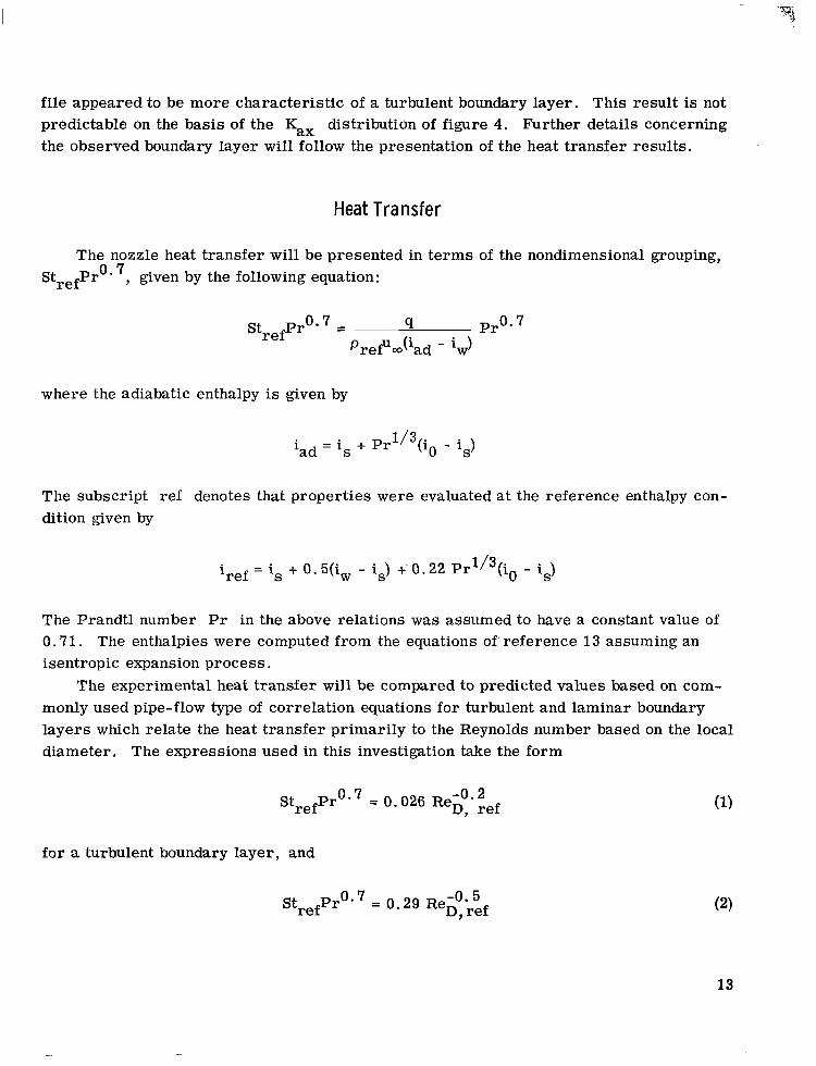
The nozzle heat transfer will be presented in te rms of the nondimensional grouping, StrefPr0* 7, given by the following equation:
StrefPro*7 = 4 Pro. u (i d - i ) Pref Q, a w
where the adiabatic enthalpy is given by
'ad . = is + pr1/3(i0 - is)
The subscript ref denotes that properties were evaluated at the reference enthalpy con- dition given by
iref = is + 0 . 5(iw - is) +' 0.22 pr1/3(i0 - is)
The Prandtl number Pr in the above relations was assumed to have a constant value of 0.71. The enthalpies were computed from the equations of'reference 13 assuming an isentropic expansion process.
The experimental heat transfer will be compared to predicted values based on com- monly used pipe-flow type of correlation equations for turbulent and laminar boundary layers which relate the heat t ransfer primarily to the Reynolds number based on the local diameter. The expressions used in this investigation take the form
-0.2 StrefPro'7 = 0.026 ReD, ref
for a turbulent boundary layer, and
StrefPros7 = 0.29 ReD, - 0 . 5 ref
13

a'
I"
for a laminar boundary layer. The Reynolds number Re,,, ref based on the local diam- eter is given by
P refu mD
EL ref re^, ref =
Experimental and predicted values of Strefpro' are presented as a function of for the 30' and 60' nozzles in figures 5 and 6, respectively. The experimental re^. ref -
heat-transfer resul ts were obtained a t a nominal stagnation temperature of 970" R (539 K) 5 5 and stagnation pressures ranging from 2.0 to 20.4 atmospheres (2.03x10 to 20.67x10
40x10-4 Stagnation pressure,
i 2.0 ( 2 . 0 3 ~ 1 0 ~ ) I I I
0 L
I1 - -
-I I
I I I Station,
(see fig. 1) D 2 v 3 A 4 h 5 0 6 v 7 A 8 0 9 0 10
Solid symbols denote conditions in which boundarv-laver sur -
boundary layer (eq. ( Z P Correlation for laminar
1.-. L- I 1 I 6 8 10 20
Reynolds number, Reo, ref
1 -. I I
Figure 5. - Heat transfer as function of Reynolds number for various stations in 30" nozzle. Nominal stagnation temperature, T'@ 970" R (539 K).
14
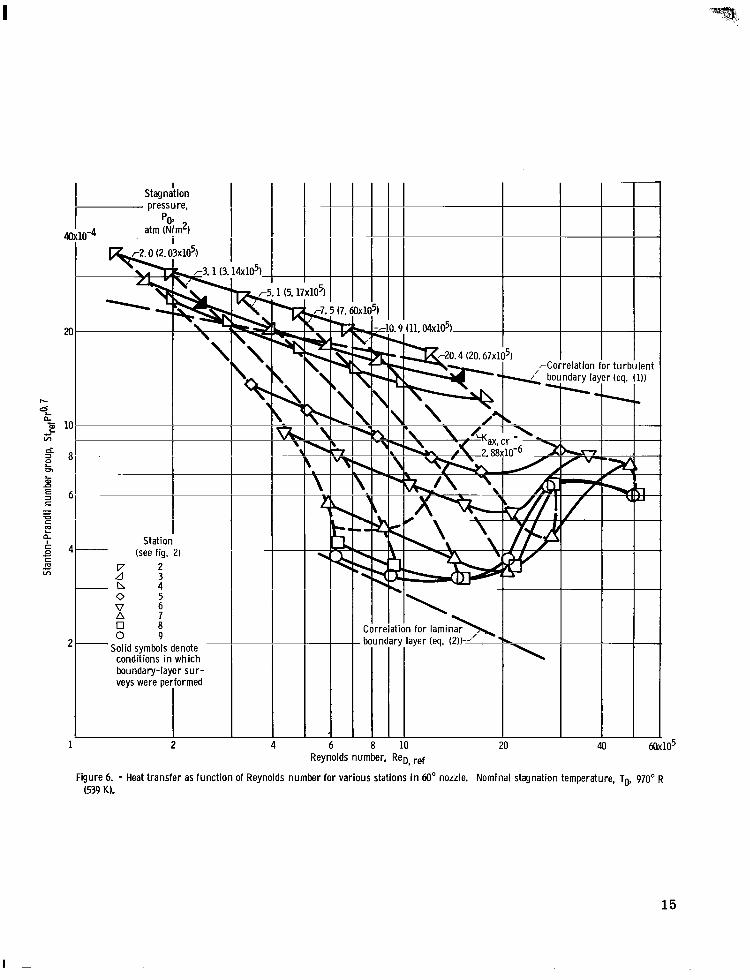
I Stagnation pressure,
atm (N!m2) Pg.
0-4 I
r 2 . 0 (2. 03x1O5.) * I
i
Station (see fig. 2) -
V 2 d 3 - n 4 0 5 V 6 A 7 0 8 0 9
- Solid symbols denote conditions in which boundary-layer sur- veys were performed
I
1 2 8 10 20 Reynolds number, ReD, ref
dary la: -.
105
Figure 6. - Heat transfer as function of Reynolds number for various stations i n 60" nozzle. Nominal stagnation temperature, To, 970" R (539 K).
15
I

.. .... . .. . .... . . . . . - .. I, I, I, , , . ,
2 N/m ). Experimental values of StrefPr0. are presented for stations 2 to 10 in the 30' nozzle and for stations 2 to 9 in the 60' nozzle. Station 2 is located near the nozzle entrance and stations 9 and 10 correspond to the geometric throats in the 60' and 30' nozzles, respectively (refer to figs. 1 and 2). The lines of constant stagnation pres- sure, which have been c ross plotted in figures 5 and 6, connect each of these stations in the nozzle and denote data which are consistent with a given test at the designated stagna- tion pressure.
The predicted heat transfer based on correlation equations (1) and (2) for turbulent and laminar boundary layers, respectively, merely provides an approximate upper and lower bound for the experimental values of StrefPr0' '. The experimental heat transfer at a given station in each nozzle generally exhibits two distinct depressions from the predicted values based on the turbulent boundary-layer correlation. Exceptions to this result can be noted at stations 2, 3, and 4 in the 60' nozzle (fig. 6). The depression in heat transfer at a given station is lower a t low Reynolds numbers or, in te rms of a fixed Reynolds number, the depression is greatest in or near the throat of the nozzle. A t high Reynolds numbers (Re,,, ref =- - 2.OX1O6 and 3.0X10 for the 30' and 60' nozzle, re- spectively), the heat transfer at the throat is only about 50 percent of the values based on the turbulent boundary -layer correlation; however, the throat heat transfer, although appreciably reduced, is still about three t imes greater than predictions based on the laminar boundary-layer correlation (eq. (2)). The 60' nozzle throat heat transfer at the highest Reynolds numbers was about 13 percent greater than corresponding values in the 30' nozzle.
The throat heat transfer in the two nozzles at Reynolds numbers below about 10 was essentially equal to the predicted values based on the laminar boundary-layer correlation. The throat heat transfer in the 60' nozzle was about 20 percent higher than the values in the 30' nozzle. Figure 5 shows that, in the lower Reynolds number regime, the experi- mental heat t ransfer at the upstream station in the 30' nozzle was within -20 percent of the predictions based on the turbulent boundary-layer correlation; however, in progres- sing downstream the heat transfer approached the laminar values. In the 60' nozzle, the upstream heat transfer exceeded values based on the turbulent boundary-layer correla- tion by as much as 40 percent; however, as in the 30' nozzle, the heat transfer ap- proached laminar levels near the throat. The high values of upstream heat transfer (StrefPro* 7, in the 60' nozzle are attributed primarily to a velocity level which is lower in the nozzle entrance than one-dimensional (pipe flow) values. This seduced velocity is the result of abrupt turning at the entrance of the 60' nozzle. The use of one-dimensional values of velocity in the computation of StrefPro. '7 and R e ~ , r e f shifts the station 2 dis- tribution in figure 6 to within a few percent of the predictions based on equation (1).
Laminarization of the boundary layer is believed to occur in the low Reynolds number range because the heat transfer, which was characterist ic of a turbulent boundary layer
6
6
16
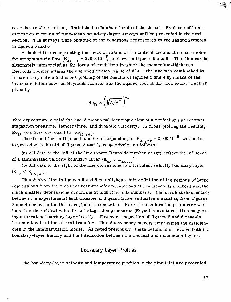
near the nozzle entrance, diminished to laminar levels at the throat. Evidence of lami- narization in te rms of time-mean boundary-layer surveys will be presented in the next section. The surveys were obtained at the conditions represented by the shaded symbols in figures 5 and 6.
A dashed line representing the locus of values of the critical acceleration parameter for axisymmetric flow Kax, cr = 2. 88X10e6) is shown in figures 5 and 6. This line can be alternately interpreted as the locus of conditions in which the momentum-thickness Reynolds number attains the assumed critical value of 360. The line was established by linear interpolation and cross plotting of the results of figures 3 and 4 by means of the inverse relation between Reynolds number and the square root of the area ratio, which is given by
(
This expression is valid for one-dimensional isentropic flow of a perfect gas at constant stagnation pressure, temperature, and dynamic viscosity. In c ros s plotting the results , ReD was assumed equal to ReD, ref.
The dashed line in figures 5 and 6 corresponding to Kax, cr = 2 . 88X10-6 can be in- terpreted with the aid of figures 3 and 4, respectively, as follows:
(a) A l l data to the left of the line (lower Reynolds number range) reflect the influence
(b) A l l data to the right of the line correspond to a turbulent velocity boundary layer of a laminarized velocity boundary layer (Kax > Kax , cr)
wax < K ax, c r ) *
This dashed line in figures 5 and 6 establishes a fair definition of the regions of large depressions from the turbulent heat-transfer predictions at low Reynolds numbers and the much smaller depressions occurring at high Reynolds numbers. The greatest discrepancy between the experimental heat transfer and quantitative estimates emanating from figures 3 and 4 occurs in the throat region of the nozzles. Here the acceleration parameter was less than the critical value for all stagnation pressures (Reynolds numbers), thus suggest- ing a turbulent boundary layer locally. However, inspection of figures 5 and 6 reveals laminar levels of throat heat transfer. This discrepancy merely emphasizes the deficien- cies in the laminarization model. As noted previously, these deficiencies involve both the boundary-layer history and the interaction between the thermal and momentum layers.
Bo u nda r y- La ye r P r of i I es
The boundary-layer velocity and temperature profiles in the pipe inlet are presented
17

I -
I I I I I I I I I I
T,, Wsec mlsec 4 4
Stagnation Wall tem- Velocity, Velocity-layer Thermal-layer pressure, perat u re, &, thickness, thickness, E " R K in. cm in. cm
1.0
.8
. 6
1.0 .4
0 . 2 . 4 .6 .8 Wall distance parameter, ylb
(a) Velocity profiles.
0. : .'
L 0.891 ! 1.173 I
I i i 1
Wall distance parameter, y/A
(b) Temperature profiles.
Figure 7. - Boundary-layer velocity and temperature profiles in pipe inlet. Nominal stagnation temperature, To, 970" R (539 K).
in figure 7 . These surveys were obtained at a nominal stagnation temperature To of
3.14xlO N/m ). The experimental results are compared with profiles based on 1/7- and 1/2-power laws, which, as noted in reference 14, have been commonly used to classify the flow regime. In reference 14, velocity profiles having power laws of 1/2 to 1/11 were measured in favorable pressure gradient flows over a centerbody near Mach 1 .0 . The profiles, characterized by power laws in the range of 1/7 to 1/11, were associated with a turbulent boundary layer, whereas profiles having a power law of 1/2 were associated with a laminar boundary layer. In this investigation, the arbitrari ly selected 1/7- and 1/2-power laws will be assumed to represent a turbulent and a laminar boundary layer, respectively, and will be used as a reference in the interpretation of the measured pro- files.
970' R (539 K) and stagnation pressure Po of 20.4 and 3.1 atmospheres (20 .67~10 5 and 5 2
18
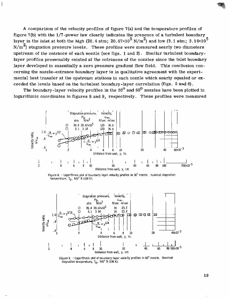
A comparison of the velocity profiles of figure 7(a) and the temperature profiles of figure 7(b) with the 1/7-power law clearly indicates the presence of a turbulent boundary
5 2 5 layer in the inlet at both the high (20.4 atm; 20.67x10 N/m ) and low (3.1 atm; 3.14X10 N/m ) stagnation pressure levels. These profiles were measured nearly two diameters upstream of the entrance of each nozzle (see figs. 1 and 2). Similar turbulent boundary- layer profiles presumably existed at the entrances of the nozzles since the inlet boundary layer developed in essentially a zero pressure gradient flow field. This conclusion con- cerning the nozzle-entrance boundary layer is in qualitative agreement with the experi- mental heat transfer at the upstream stations in each nozzle which nearly equaled o r ex- ceeded the levels based on the turbulent boundary-layer correlation (figs. 5 and 6).
The boundary-layer velocity profiles in the 30' and 60' nozzles have been plotted in logarithmic coordinates in figures 8 and 9, respectively. These profiles were measured
2
StagnatiAn preshre , Velocity, PO.
atm N/m2 fllsec mlsec
c
20 al
2 4 6 8 10 >
1 ~~
Distance from wall, y, in.
I I I I& 40 60 80 100 200~10-3
I I I I I I I I I 4 6 8 10 20
I 2
Distance from wall, y, cm
Figure 8. - Logarithmic plot of boundary-layer velocity profiles in 30" nozzle, Nominal stagnation temperature, To, 970" R (539 K).
PO I
atm Nlm2 ftlsec mlsec 0 20.4'20.67~10~ 76 23.2
20 Distance from wall, y, in.
I I I I I I I 4 6 8 10
I 2
I u 40 60 80 100~10-3
I 20
Distance from wall, y, cm
Figure 9. - Logarithmic plot of boundary-layer velocity profiles in 60" nozzle. Nominal stagnation temperature, To, 970" R (539 K).
19

at the same stagnation conditions as the inlet boundary-layer surveys. The velocity pro- file at a stagnation pressure of 20.4 atmospheres (20.67XlO N/m ) was nearly identical to the profiles reported in references 8 and 9, which were obtained under similar operat- ing conditions. In references 8 and 9, an adiabatic ra ther than a cooled inlet was coupled to the present. nozzle. It was noted in references 8 and 9 that the velocity boundary-layer thickness 6 established in the conventional manner was quite ambiguous because of the flatness of the portion of the boundary layer extending from about 0.01 inch (0.025 cm) to the freestream. Futile attempts to correlate these profiles on the basis of a power law in which 6 was selected in the outer "flat" portion of the profile resulted in the questioning of the power profile assumption when applied to nozzle flows. In the data of figures 8 and 9, only the portion of the boundary layer corresponding to y minus about 0.007 inch (0.0178 cm) can be correlated on the basis of a power law within the previously pre- scribed limits; however, the boundary layer appears to extend as far as y M 0.06 inch (0.152 cm) in the 30' nozzle and y M 0.02 inch (0.051 cm) in the 60' nozzle (figs. 8 and 9, respectively). The inner portion of the boundary layer at the high stagnation pres- Sure (20.4 atm; 20.67xlO N/m ) appeared to correlate on the basis of 1/7- and 1/11- power laws corresponding to the 30' and 60' nozzles, respectively. A t the low stagna- tion pressure (3.1 atm; 3.14X10 N/m ), the portion of the boundary layer in which y < 0.007 inch (0.0178 cm) can be correlated reasonably well on the basis of a 1/4-power law, but, again, the boundary layer may extend considerably beyond y 0.007 inch (0.0178 cm).
An unconventional assumption that has not yet been validated for nozzle-type flows is necessary in order to permit the analysis of these boundary layers on the basis of con- ventional power profiles. This assumption is to ignore the outer flow region completely, thus implying that the turbulent exchange mechanisms contributing to the production of shear at the wall are of predominant importance in the inner power-law portion of the boundary layer. The velocity boundary-layer thickness 6 will, therefore, be determined by extrapolation of the inner par t of the measured profile to u/um = 0.99 (figs. 8 and 9).
The boundary-layer velocity profiles in the 30' and 60' nozzles a r e plotted in rec- tangular coordinates in figures lO(a) and 1 l(a), respectively. The corresponding tempera- ture profiles at the nozzle survey station are shown in figures 1O(b) and l l (b) . The velocity and temperature profiles in the two nozzles at the high stagnation pressure (20.4 atm; 20.67xlO N/m ) are essentially correlated by power laws in the range of 1/7 to 1/11, thus implying a turbulent boundary layer. Furthermore, the heat transfer at these con- ditions, denoted by the shaded symbols at ReD, ref = 2.1X10 respectively), is in good agreement with the turbulent boundary-layer correlation.
3.14xlO N/m ) is also characteristic of a turbulent boundary layer as denoted by the correlation with a 1/7-power profile in figures 1O(b) and l l(b). However, the velocity pro-
5 2
5 2
5 2
5 2
6 6 and 1.5X10 (figs. 5 and 6,
The thermal boundary layer in the nozzles at the low stagnation pressure (3.1 atm; 5 2
20

I I I I I I I I I I I I I
Po. T,, ft/sec mlsec 6, 4
Stagnation Wall tem- Velocity, Velocity-layer Thermal-layei pressure, peratu re, u thickness, thickness, t 0 20.4 20.67~10~ 755 420 120 36.6 0.0076 0.0193 0.516 1.31
atm N/m2 "R K in. cm in. cm
Wall distance parameter, yl6
(a) Velocity profiles.
0 .2 . 4 .6 .8
.521 1.32
$E Wall distance parameter, y lA
(b) Temperature profiles.
Figure 10. - Boundary-layer velocity and temperature profiles in M" nozzle. Nominal stagnation temperature, To, 970" R (539 K).
files, shown in figures 8, 9, lO(a), and ll(a), have been altered by the reduction in stag- nation pressure. The profile lies between the 1/7-power turbulent and l/Z-power lami- nar profiles, thereby suggesting a transition towards the laminar-type boundary layer.
The heat transfer in the 30' nozzle corresponding to the conditions of the low- stagnation-pressure boundary-layer survey is denoted by the solid symbol at ReD, ref - -
5 3.6X10 in figure 5. The heat transfer at the survey station was depressed to 60 percent of the value based on the turbulent boundary-layer correlation. In continuing along the line of constant stagnation pressure in figure 5, it can be noted that the throat heat trans- fer was in good agreement with predictions based on the laminar boundary-layer correla- tion.
The heat transfer at the boundary-layer survey station in the 60' nozzle is denoted by the solid symbols in figure 6 at Re,,, ref = 2. &lo5. In this case, a depression from the
21

I l l I 1 Stagnation Wall tem- Velocity, Velocity-layer Thermal-layer pressure, perat u re, u,, thickness,
atm N/m2 "R K in. cm 0 20.4 2O.67x1O5 714 397 76 23.2 0 . W 0.011
Tw, ftlsec mlsec 6,
1.0
.a
.6
0 . 2 . 4 . 6 .a 1.0 Wall distance parameter, yl6
.4
(a) Velocity profiles,
0 . 2 . 4 .6 .a 1.0 Wall distance parameter, y lA
(bI Temperature profiles.
thickness,
in. cm
.706 1.793
. 4
0.735 1. a67
I I ~
~
Figure 11. - Boundary-layer velocity and temperature profiles in 60" nozzle, Nominal stagnation temperature, To, 970" R (539 KI.
predicted heat transfer for a turbulent boundary layer is not apparent at the survey sta- tions; however, in progressing downstream along the line of constant stagnation pres- sure , the heat transfer approaches the laminar prediction.
nozzle at a given stagnation pressure (figs. 7, 10, and 11). In the inlet, the values of 6 and A were comparable; in the nozzle, however, the velocity boundary layer was much thinner than the thermal boundary layer (6 << A ) . The thermal boundary layer between the survey stations in the inlet and nozzle was not significantly affected by the flow accel eration but thickened primarily because of increasing heat transfer and boundary -layer length. Considering the measured laminar-type velocity profile in the nozzles, the vis- cous dissipation is expected to be greatly reduced from that of the usually assumed tur- bulent l/?-power velocity profile. Assuming this laminar-type velocity profile pers is ts
It is interesting to note the relative thickness of the boundary layer in the inlet and
22
at least to the nozzle throat, where the viscous dissipation is definitely a significant ef- fect, the heat transfer can be greatly reduced.
DISCUSS ION
The depressions from the predicted heat transfer based on the turbulent pipe flow type of correlation have been known to be associated with the reduction in turbulence in- tensity which accompanies flow acceleration. The results of this investigation support the feasibility of using a critical acceleration parameter Kax, cr to predict the regions of small and large depressions in the heat transfer. The value of Kax, cr (2.88X10- ) is based primarily on the assumption that laminarization occurs at a critical momentum- thickness Reynolds number of 360, which is the classical value for forward transition on a flat plate.
In reference 3 it was noted that the depressions in heat transfer a t high Reynolds numbers (Kax < Kax, cr ) might be adequately accounted for by applying a correction fac- tor involving Kax to an energy-type prediction of the heat transfer. In reference 4, the application of a correction factor involving Kax to data in which Kax < Kax, cr resulted in a good prediction of the heat transfer in a two-dimensional nozzle. Unfortunately, the use of the acceleration parameter in predicting the highly depressed heat transfer at low Reynolds numbers is unknown. Therefore, caution should be exercised in applying lami- nar heat-transfer predictions to an initially turbulent flow even though Kax > Kax, cr. It has been demonstrated, however, that when Kax > Kax, cr reductions in the normal levels of turbulent heat transfer can be expected.
6
SUMMARY OF RESULTS
Heat-transfer measurements were obtained in 30' and 60' half -angle of convergence nozzles at a nominal stagnation temperature of 970' R (539 K) and over a range of stagna- tion pressures of about 2.0 to 20.4 atmospheres (2: 05x10 to 20.67X10 N/m ). These
5 pressure levels provided throat Reynolds numbers based on diameter of about 6.0XlO to 5.OXlO . Additionally, time-mean boundary-layer velocity and temperature measure- ments were obtained at one station in a water-cooled pipe inlet and at a subsonic (Mach number S O . 08) station in each nozzle at stagnation pressures of 3.1 and 20.4 atmospheres (3.14X10 and 20.67xlO N/m2). The principal results of this study can be summarized as follows:
1. Inlet velocity and temperature profiles at the aforementioned stagnation pressure levels were characteristic of those for turbulent pipe flow; that is, the profiles were es- sentially described by a 1/7 -power law. Although these measurements were obtained
5 5 2
6
5 5
23
nearly two diameters upstream of the nozzle, s imilar turbulent boundary -layer profiles were presumed to exist at the entrance of the nozzle.
depressions from predicted resul ts based on a turbulent pipe-flow type of correlation. The smaller of the two depressions occurred at the higher Reynolds numbers where, in progressing downstream, the heat -transfer departure f rom predicted levels increased. A t the throat of each nozzle, the heat t ransfer was about 50 percent of the predicted value.
A larger depression f rom the turbulent flow predictions of heat transfer occurred at the lower Reynolds numbers where there was evidence of laminarization of the initially turbulent velocity boundary layer. A t these conditions, the throat heat transfer was ap- proximately predictable by a laminar pipe -flow type of correlation.
cent higher than in the 30' half-angle of convergence nozzle at the highest Reynolds num- ber , and it was about 20 percent higher at the lowest Reynolds number.
boundary-layer velocity and tempera- ture surveys at a subsonic station in each nozzle yielded profiles which were essentially characteristic of turbulent pipe flow. The heat transfer at the survey station was within a few percent of the turbulent flow prediction.
Nozzle surveys at a lower stagnation pressure (3.1 atm; 3.14X10 N/m ) revealed turbulent thermal boundary-layer profiles essentially described by a 1/7 -power profile; however, the velocity profiles were of a laminar type corresponding to about a 1/4-power profile. Under these conditions the heat t ransfer at the survey station in the 30' half- angle of convergence nozzle was already depressed to 60 percent of the turbulent flow prediction; however, a depression in the survey-station heat transfer in the 60' half- angle of convergence nozzle was not apparent.
4. In progressing from the inlet to the survey station in each nozzle, the thermal boundary layer thickened; however, the velocity boundary layer diminished appreciably. Consequently, the thermal boundary layer a t the nozzle survey station was much thicker than the velocity boundary layer .
integral momentum equation, provided a fair definition of the conditions in which the heat transfer was influenced by laminarization. The critical value of the axisymmetric accel- eration parameter (2. 88X10-6) w a s based primarily on the assumption that laminarization occurs at a momentum-thickness Reynolds number of 360, which corresponds to the value for forward transition on a flat plate.
2. The heat t ransfer at a given station in each nozzle generally exhibited two distinct
The throat heat transfer in the 60' half-angle of convergence nozzle was about 13 per-
3 . High Reynolds number ReD, ref = 2.0XlO ( ?
5 2
5. A critical value of the axisymmetric acceleration parameter, derived from the
Lewis Research Center, National Aeronautics and Space Administration,
Cleveland, Ohio, May 13, 1968, 129-01-11-04-22.
24
APPENDIX A
FURTHER CONSIDERATION OF ERROR IN EXPERIMENTAL HEAT TRANSFER
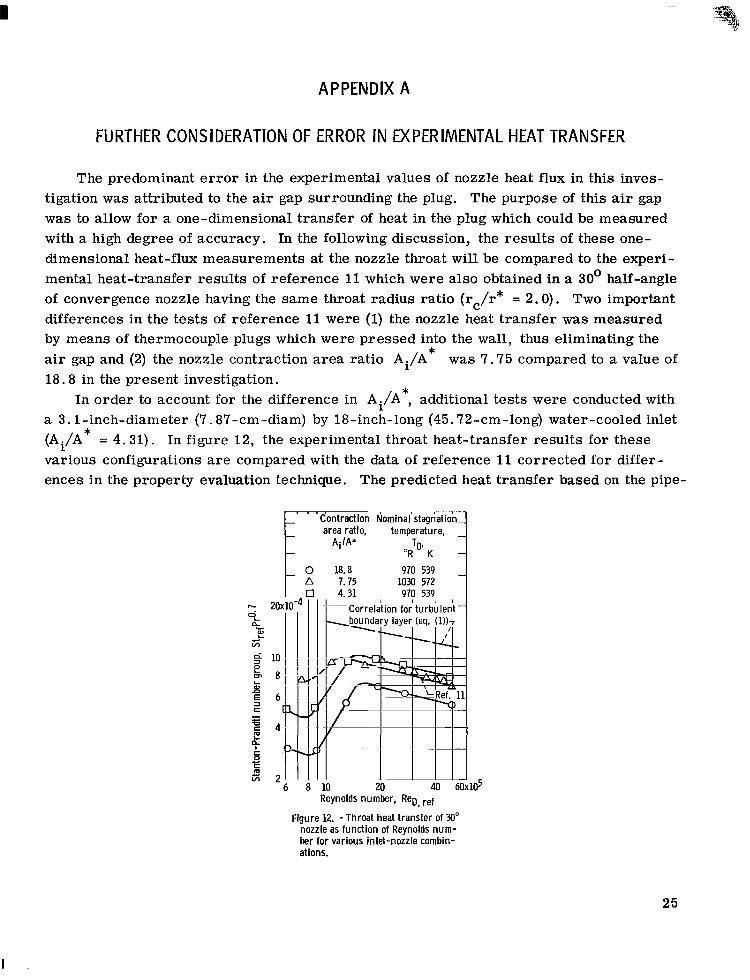
The predominant e r r o r in the experimental values of nozzle heat flux in this inves- tigation was attributed to the air gap surrounding the plug. The purpose of this air gap was to allow for a one-dimensional transfer of heat in the plug which could be measured with a high degree of accuracy. In the following discussion, the resul ts of these one- dimensional heat-flux measurements at the nozzle throat will be compared to the experi- mental heat-transfer results of reference 11 which were also obtained in a 30' half-angle of convergence nozzle having the same throat radius ratio (rc/r* = 2.0). Two important differences in the tests of reference 11 were (1) the nozzle heat transfer was measured by means of thermocouple plugs which were pressed into the wall, thus eliminating the air gap and (2) the nozzle contraction area ratio Ai/A was 7.75 compared to a value of 18.8 in the present investigation.
In order to account for the difference in Ai/A , additional tes ts were conducted with a 3.1-inch-diameter (7.87-cm-diam) by 18-inch-long (45.72-cm-long) water-cooled inlet (Ai/A various configurations are compared with the data of reference 11 corrected for differ- ences in the property evaluation technique. The predicted heat transfer based on the pipe-
*
*
* = 4.31). In figure 12 , the experimental throat heat-transfer results for these
k' ' 'Contraction Nominal'stwiatioinJ area ratio, temperature,
Ai/A* TO* "R K
Reynolds number, ReD, ref
Figure 12. -Throat heat transfer of 30" nozzle as function of Reynolds num- ber for various inlet-nozzle combin- ations.
25
I
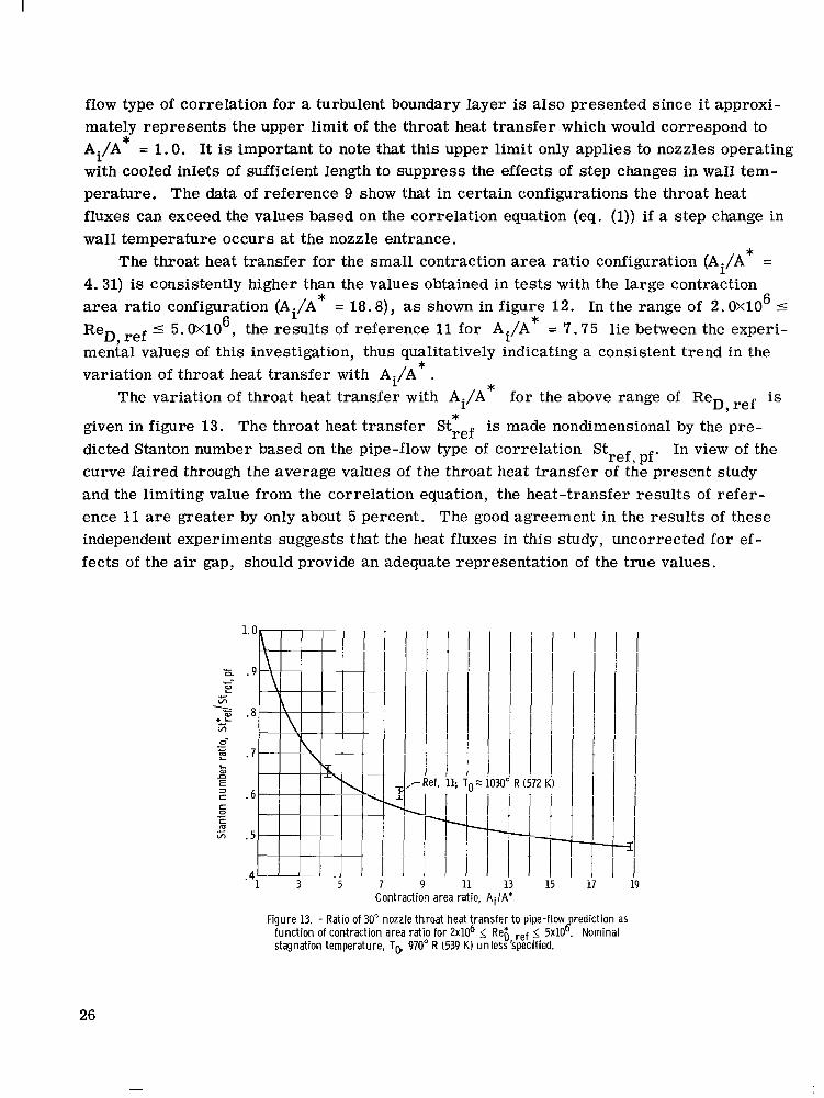
flow type of correlation for a turbulent boundary layer is also presented since it approxi- mately represents the upper limit of the throat heat transfer which would correspond to Ai/A* = 1.0. It is important to note that this upper limit only applies to nozzles operating with cooled inlets of sufficient length to suppress the effects of step changes in wall tem- perature. The data of reference 9 show that in certain configurations the throat heat fluxes can exceed the values based on the correlation equation (eq. (1)) if a step change in wall temperature occurs at the nozzle entrance.
The throat heat transfer for the small contraction area ratio configuration (Ai/A 4.31) is consistently higher than the values obtained in tests with the large contraction area ratio configuration (Ai/A = 18.8), as shown in figure 12. In the range of 2.0XlO I
-C 5.OX1O6, the results of reference 11 for Ai/A = 7.75 lie between the experi- re^, ref - mental values of this investigation, thus qualitatively indicating a consistent trend in the variation of throat heat transfer with Ai/A .
for the above range of ReD, ref is
given in figure 13. The throat heat t ransfer Stref is made nondimensional by the pre- dicted Stanton number based on the pipe-flow type of correlation Stref, pf. In view of the curve faired through the average values of the throat heat transfer of the present study and the limiting value from the correlation equation, the heat-transfer results of refer- ence 11 a r e greater by only about 5 percent. The good agreement in the resul ts of these independent experiments suggests that the heat fluxes in this study, uncorrected for ef- fects of the air gap, should provide an adequate representation of the t rue values.
* =
* 6 *
* *
The variation of throat heat transfer with Ai/A *
1.0
.9 i E
E .a si - =siL
p .7
c . 6
0- .- c
E 3 c 0 c r m c I/) .5
1 3 5 . 4
7
J I M- I I I I
! I
9 11 13 15 Contraction area ratio, A i /A*
Figure 13. - Ratio of 30" nozzle throat heat transfer to pipe-flow rediction as
stagnation temperature, To, 970" R (539 K) unless specified. function of contraction area rat io for 2x10⁶ 5 Rei), ref 5. 5x10 8 . . Nominal
26

APPENDIX B
AX I SYMMETR IC ACCELERATION PARAMETER
In reference 3 an axisymmetric acceleration parameter was derived from the integral momentum equation. Flat-plate relations for the form factor and friction law were in- corporated in the momentum equation in order to obtain the appropriate grouping of te rms which are postulated to define the boundary conditions for laminarization of an initially turbulent boundary layer. In contrast to the analysis of reference 3, the following deriva- tion will entail the use of the empirical relation of reference 12 for the shear stress, pressure gradient, and form factor. This relation, which was derived from experimental studies in an 8' half-angle of convergence conical nozzle, should be more applicable to the present investigation than the flat-plate empiricisms used in reference 3.
The integral momentum equation has the following form:
Multiplying equation (€31) by p , u d ~ ~ and rearranging yields
dReO Ree du, +---- Ree dr - rw + ( H + l ) --
where the dynamic viscosity p is assumed constant and equal to the viscosity at the stagnation temperature ( p = po) . In reference 12 a shear-s t ress parameter E and the form factor H = 6 / e were expressed as functions of a pressure-gradient parameter r, where E and r a r e given by the following equations:
*
Multiplication of equation (B2) by the following alternate form of the momentum equation:
and substitution of equations (B3) and (B4) gives
27
I .
In reference 12 the bracketed group of te rms on the right s ide of equation (B5) were found to be dependent on the pressure-gradient parameter as shown by equation (B6).
Substitution of equations (B6) and (B4) into equation (B5) yields the following equation for the momentum-thickness Reynolds number distribution in the nozzle :
037) dum pca',
dReg 5/4 - + 3.55- -- - 0.016 - d r
dx 4 r d x dx
5/4 5 + - -
PO
Equation (B7) can be readily solved for the change in Reg with distance x to give
In the highly accelerated flow in a nozzle, dReg/dx attains a negative value, thus indi- cating a reduction in Ree with increasing distance x. If the value of Ree becomes sufficiently low, laminarization of the boundary layer is postulated to occur. The critical Reynolds number at which laminarization occurs will be assumed equal to the critical value for forward transition on a flat plate (Reg, cr = 360). Substitution of Reg, cr = Ree = 360 into equation (B8) yields
+ 0.352 - - dx 5 v,
where the axisymmetric acceleration parameter Kax is given by the te rms in the inner brackets; that is,
28
In order for laminarization to occur, the value of dRee/dx at Ree = Ree, cr must be less than zero. Consequently, the following inequality, derived from equation (B9), must be satisfied:
+ 0.352 - v m - &) > 2. 88X10-6 u,r dx
The critical value of the acceleration parameter is, therefore, given by
This value for the critical acceleration parameter is between the critical values used for the two-dimensional acceleration parameter ( v, /!ut)(&,/&) in references 3 and 4.
29
I
I -
REFER ENC ES
1. Back, L. H.; Massier, P. F. ; and Cuffel, R. F. : Some Observations on Reduction of Turbulent Boundary-Layer Heat Transfer in Nozzles. AIAA J . , vol. 4, no. 12, Dec. 1966, pp. 2226-2229.
2. Launder, B. E. : Laminarization of the Turbulent Boundary Layer in a Severe Accel- eration. J. Appl. Mech., vol. 31, no. 4, Dec. 1964, pp. 707-708.
3. Moretti, P. M. ; and Kays, W. M. : Heat Transfer Through an Incompressible Tur- bulent Boundary Layer With Varying Free-Stream Velocity and Varying Surface Temperature. Rep. No. PG-1, Thermosciences Div., Mech. Eng. Dept., Stanford Univ., Nov. 1964.
4. Back, L. H. ; and Seban, R. A . : Flow and Heat Transfer in a Turbulent Boundary Layer With Large Acceleration Parameter . Proceedings of the 1967 Heat Transfer and Fluid Mechanics Institute. P. A . Libby, D. B. Olfe, and C. W. VanAtta, eds . , Stanford Univ. Press, 1967, pp. 410-426.
5. O'Brien, R. L. ; and Demarest, P. E. : Laminarization of Nozzle Wall Boundary Layers as a Means of Reducing Heat Flux. Rep. C910100-15, United Aircraft Corp., Oct. 1964. (Available from DDC as AD-460927.)
6. Talmor, E. : Sonic-Point Heat Transfer at Various Degrees of Upstream Accelera- tion. Paper No. 27, AIChE and ASME 9th National Heat Transfer Conference, Seattle, Wash., Aug. 6-9, 1967.
7. Schraub, F. A . ; and Kline, S. J. : A Study of the Structure of the Turbulent Bound- a ry Layer With and Without Longitudinal Pressure Gradients. Rep. No. MD-12, Thermosciences Div., Mech. Eng. Dept., Stanford Univ., Mar. 1965.
8. Boldman, Donald R. ; Schmidt, James F. ; and Fortini, Anthony: Turbulence, Heat- Transfer, and Boundary Layer Measurements in a Conical Nozzle With a Controlled Inlet Velocity Profile. NASA TN D-3221, 1966.
9. Boldman, D. R. ; Schmidt, J. F. ; and Ehlers, R. C. : Effect of Uncooled Inlet Length and Nozzle Convergence Angle on the Turbulent Boundary Layer and Heat- Transfer in Conical Nozzles Operating With A i r . J. Heat Transfer, vol. 89, no. 4, Nov. 1967, pp. 341-350.
in 30' and 60' Half-Angle of Convergence Nozzles With Various Diameter Uncooled Pipe Inlets. NASA TN D-4177, 1967.
10. Boldman, Donald R. ; Neumann, Harvey E. ; and Schmidt, James F. : Heat Transfer
30
11. Back, L. H.; Massier, P. F.; and Gier, H. L. : Convective Heat Transfer in a Convergent-Divergent Nozzle. Rep. TR-32-415, rev. 1 , Jet Propulsion Lab. , California Inst. Tech. (NASA CR-57326), Feb. 15, 1965.
12. Romanenko, P. N. ; Leont'yev, A. I. ; and Oblivin, A. N. : Investigation of Drag and Heat Transfer During A i r Motion in Divergent and Convergent Nozzles. NASA TTF-11221, 1967.
13. McBride, Bonnie J. ; Heimel, Sheldon; Ehlers, Janet G. ; and Gordon, Sanford: Thermodynamic Properties to 6000' K for 210 Substances Involving the First 18 Elements. NASA SP-3001, 1963.
14. Wesoky, Howard L. : Boundary-Layer Measurements in Accelerated Flows Near Mach 1. NASA TN D-3882, 1967.
E-4276 NASA-Langley, 1968 - 12 31
I